WO2018212508A2 - Cartridge for nucleic acid extraction and nucleic acid extraction method - Google Patents
Cartridge for nucleic acid extraction and nucleic acid extraction methodDownload PDFInfo
- Publication number
- WO2018212508A2 WO2018212508A2PCT/KR2018/005428KR2018005428WWO2018212508A2WO 2018212508 A2WO2018212508 A2WO 2018212508A2KR 2018005428 WKR2018005428 WKR 2018005428WWO 2018212508 A2WO2018212508 A2WO 2018212508A2
- Authority
- WO
- WIPO (PCT)
- Prior art keywords
- nucleic acid
- chamber
- acid amplification
- cartridge
- pretreatment
- Prior art date
- Legal status (The legal status is an assumption and is not a legal conclusion. Google has not performed a legal analysis and makes no representation as to the accuracy of the status listed.)
- Ceased
Links
Images


Classifications
- B—PERFORMING OPERATIONS; TRANSPORTING
- B01—PHYSICAL OR CHEMICAL PROCESSES OR APPARATUS IN GENERAL
- B01L—CHEMICAL OR PHYSICAL LABORATORY APPARATUS FOR GENERAL USE
- B01L3/00—Containers or dishes for laboratory use, e.g. laboratory glassware; Droppers
- B01L3/50—Containers for the purpose of retaining a material to be analysed, e.g. test tubes
- B01L3/502—Containers for the purpose of retaining a material to be analysed, e.g. test tubes with fluid transport, e.g. in multi-compartment structures
- B01L3/5027—Containers for the purpose of retaining a material to be analysed, e.g. test tubes with fluid transport, e.g. in multi-compartment structures by integrated microfluidic structures, i.e. dimensions of channels and chambers are such that surface tension forces are important, e.g. lab-on-a-chip
- B01L3/502738—Containers for the purpose of retaining a material to be analysed, e.g. test tubes with fluid transport, e.g. in multi-compartment structures by integrated microfluidic structures, i.e. dimensions of channels and chambers are such that surface tension forces are important, e.g. lab-on-a-chip characterised by integrated valves
- B—PERFORMING OPERATIONS; TRANSPORTING
- B01—PHYSICAL OR CHEMICAL PROCESSES OR APPARATUS IN GENERAL
- B01L—CHEMICAL OR PHYSICAL LABORATORY APPARATUS FOR GENERAL USE
- B01L3/00—Containers or dishes for laboratory use, e.g. laboratory glassware; Droppers
- B01L3/50—Containers for the purpose of retaining a material to be analysed, e.g. test tubes
- B01L3/502—Containers for the purpose of retaining a material to be analysed, e.g. test tubes with fluid transport, e.g. in multi-compartment structures
- B01L3/5027—Containers for the purpose of retaining a material to be analysed, e.g. test tubes with fluid transport, e.g. in multi-compartment structures by integrated microfluidic structures, i.e. dimensions of channels and chambers are such that surface tension forces are important, e.g. lab-on-a-chip
- B01L3/50273—Containers for the purpose of retaining a material to be analysed, e.g. test tubes with fluid transport, e.g. in multi-compartment structures by integrated microfluidic structures, i.e. dimensions of channels and chambers are such that surface tension forces are important, e.g. lab-on-a-chip characterised by the means or forces applied to move the fluids
- B—PERFORMING OPERATIONS; TRANSPORTING
- B01—PHYSICAL OR CHEMICAL PROCESSES OR APPARATUS IN GENERAL
- B01L—CHEMICAL OR PHYSICAL LABORATORY APPARATUS FOR GENERAL USE
- B01L13/00—Cleaning or rinsing apparatus
- B01L13/02—Cleaning or rinsing apparatus for receptacle or instruments
- C—CHEMISTRY; METALLURGY
- C12—BIOCHEMISTRY; BEER; SPIRITS; WINE; VINEGAR; MICROBIOLOGY; ENZYMOLOGY; MUTATION OR GENETIC ENGINEERING
- C12N—MICROORGANISMS OR ENZYMES; COMPOSITIONS THEREOF; PROPAGATING, PRESERVING, OR MAINTAINING MICROORGANISMS; MUTATION OR GENETIC ENGINEERING; CULTURE MEDIA
- C12N13/00—Treatment of microorganisms or enzymes with electrical or wave energy, e.g. magnetism, sonic waves
- C—CHEMISTRY; METALLURGY
- C12—BIOCHEMISTRY; BEER; SPIRITS; WINE; VINEGAR; MICROBIOLOGY; ENZYMOLOGY; MUTATION OR GENETIC ENGINEERING
- C12N—MICROORGANISMS OR ENZYMES; COMPOSITIONS THEREOF; PROPAGATING, PRESERVING, OR MAINTAINING MICROORGANISMS; MUTATION OR GENETIC ENGINEERING; CULTURE MEDIA
- C12N15/00—Mutation or genetic engineering; DNA or RNA concerning genetic engineering, vectors, e.g. plasmids, or their isolation, preparation or purification; Use of hosts therefor
- C12N15/09—Recombinant DNA-technology
- C12N15/10—Processes for the isolation, preparation or purification of DNA or RNA
- C12N15/1003—Extracting or separating nucleic acids from biological samples, e.g. pure separation or isolation methods; Conditions, buffers or apparatuses therefor
- C12N15/1006—Extracting or separating nucleic acids from biological samples, e.g. pure separation or isolation methods; Conditions, buffers or apparatuses therefor by means of a solid support carrier, e.g. particles, polymers
- C12N15/1013—Extracting or separating nucleic acids from biological samples, e.g. pure separation or isolation methods; Conditions, buffers or apparatuses therefor by means of a solid support carrier, e.g. particles, polymers by using magnetic beads
- C—CHEMISTRY; METALLURGY
- C12—BIOCHEMISTRY; BEER; SPIRITS; WINE; VINEGAR; MICROBIOLOGY; ENZYMOLOGY; MUTATION OR GENETIC ENGINEERING
- C12Q—MEASURING OR TESTING PROCESSES INVOLVING ENZYMES, NUCLEIC ACIDS OR MICROORGANISMS; COMPOSITIONS OR TEST PAPERS THEREFOR; PROCESSES OF PREPARING SUCH COMPOSITIONS; CONDITION-RESPONSIVE CONTROL IN MICROBIOLOGICAL OR ENZYMOLOGICAL PROCESSES
- C12Q1/00—Measuring or testing processes involving enzymes, nucleic acids or microorganisms; Compositions therefor; Processes of preparing such compositions
- C12Q1/68—Measuring or testing processes involving enzymes, nucleic acids or microorganisms; Compositions therefor; Processes of preparing such compositions involving nucleic acids
- C12Q1/6844—Nucleic acid amplification reactions
- G—PHYSICS
- G01—MEASURING; TESTING
- G01N—INVESTIGATING OR ANALYSING MATERIALS BY DETERMINING THEIR CHEMICAL OR PHYSICAL PROPERTIES
- G01N1/00—Sampling; Preparing specimens for investigation
- G01N1/28—Preparing specimens for investigation including physical details of (bio-)chemical methods covered elsewhere, e.g. G01N33/50, C12Q
- G01N1/286—Preparing specimens for investigation including physical details of (bio-)chemical methods covered elsewhere, e.g. G01N33/50, C12Q involving mechanical work, e.g. chopping, disintegrating, compacting, homogenising
- G—PHYSICS
- G01—MEASURING; TESTING
- G01N—INVESTIGATING OR ANALYSING MATERIALS BY DETERMINING THEIR CHEMICAL OR PHYSICAL PROPERTIES
- G01N1/00—Sampling; Preparing specimens for investigation
- G01N1/28—Preparing specimens for investigation including physical details of (bio-)chemical methods covered elsewhere, e.g. G01N33/50, C12Q
- G01N1/34—Purifying; Cleaning
- G—PHYSICS
- G01—MEASURING; TESTING
- G01N—INVESTIGATING OR ANALYSING MATERIALS BY DETERMINING THEIR CHEMICAL OR PHYSICAL PROPERTIES
- G01N21/00—Investigating or analysing materials by the use of optical means, i.e. using sub-millimetre waves, infrared, visible or ultraviolet light
- G01N21/62—Systems in which the material investigated is excited whereby it emits light or causes a change in wavelength of the incident light
- G01N21/63—Systems in which the material investigated is excited whereby it emits light or causes a change in wavelength of the incident light optically excited
- G01N21/64—Fluorescence; Phosphorescence
- G01N21/6486—Measuring fluorescence of biological material, e.g. DNA, RNA, cells
- B—PERFORMING OPERATIONS; TRANSPORTING
- B01—PHYSICAL OR CHEMICAL PROCESSES OR APPARATUS IN GENERAL
- B01L—CHEMICAL OR PHYSICAL LABORATORY APPARATUS FOR GENERAL USE
- B01L2200/00—Solutions for specific problems relating to chemical or physical laboratory apparatus
- B01L2200/02—Adapting objects or devices to another
- B01L2200/026—Fluid interfacing between devices or objects, e.g. connectors, inlet details
- B01L2200/027—Fluid interfacing between devices or objects, e.g. connectors, inlet details for microfluidic devices
- B—PERFORMING OPERATIONS; TRANSPORTING
- B01—PHYSICAL OR CHEMICAL PROCESSES OR APPARATUS IN GENERAL
- B01L—CHEMICAL OR PHYSICAL LABORATORY APPARATUS FOR GENERAL USE
- B01L2200/00—Solutions for specific problems relating to chemical or physical laboratory apparatus
- B01L2200/06—Fluid handling related problems
- B01L2200/0621—Control of the sequence of chambers filled or emptied
- B—PERFORMING OPERATIONS; TRANSPORTING
- B01—PHYSICAL OR CHEMICAL PROCESSES OR APPARATUS IN GENERAL
- B01L—CHEMICAL OR PHYSICAL LABORATORY APPARATUS FOR GENERAL USE
- B01L2200/00—Solutions for specific problems relating to chemical or physical laboratory apparatus
- B01L2200/10—Integrating sample preparation and analysis in single entity, e.g. lab-on-a-chip concept
- B—PERFORMING OPERATIONS; TRANSPORTING
- B01—PHYSICAL OR CHEMICAL PROCESSES OR APPARATUS IN GENERAL
- B01L—CHEMICAL OR PHYSICAL LABORATORY APPARATUS FOR GENERAL USE
- B01L2200/00—Solutions for specific problems relating to chemical or physical laboratory apparatus
- B01L2200/14—Process control and prevention of errors
- B01L2200/141—Preventing contamination, tampering
- B—PERFORMING OPERATIONS; TRANSPORTING
- B01—PHYSICAL OR CHEMICAL PROCESSES OR APPARATUS IN GENERAL
- B01L—CHEMICAL OR PHYSICAL LABORATORY APPARATUS FOR GENERAL USE
- B01L2300/00—Additional constructional details
- B01L2300/04—Closures and closing means
- B01L2300/041—Connecting closures to device or container
- B—PERFORMING OPERATIONS; TRANSPORTING
- B01—PHYSICAL OR CHEMICAL PROCESSES OR APPARATUS IN GENERAL
- B01L—CHEMICAL OR PHYSICAL LABORATORY APPARATUS FOR GENERAL USE
- B01L2300/00—Additional constructional details
- B01L2300/06—Auxiliary integrated devices, integrated components
- B—PERFORMING OPERATIONS; TRANSPORTING
- B01—PHYSICAL OR CHEMICAL PROCESSES OR APPARATUS IN GENERAL
- B01L—CHEMICAL OR PHYSICAL LABORATORY APPARATUS FOR GENERAL USE
- B01L2300/00—Additional constructional details
- B01L2300/06—Auxiliary integrated devices, integrated components
- B01L2300/0627—Sensor or part of a sensor is integrated
- B01L2300/0654—Lenses; Optical fibres
- B—PERFORMING OPERATIONS; TRANSPORTING
- B01—PHYSICAL OR CHEMICAL PROCESSES OR APPARATUS IN GENERAL
- B01L—CHEMICAL OR PHYSICAL LABORATORY APPARATUS FOR GENERAL USE
- B01L2300/00—Additional constructional details
- B01L2300/06—Auxiliary integrated devices, integrated components
- B01L2300/0681—Filter
- B—PERFORMING OPERATIONS; TRANSPORTING
- B01—PHYSICAL OR CHEMICAL PROCESSES OR APPARATUS IN GENERAL
- B01L—CHEMICAL OR PHYSICAL LABORATORY APPARATUS FOR GENERAL USE
- B01L2300/00—Additional constructional details
- B01L2300/08—Geometry, shape and general structure
- B01L2300/0861—Configuration of multiple channels and/or chambers in a single devices
- B—PERFORMING OPERATIONS; TRANSPORTING
- B01—PHYSICAL OR CHEMICAL PROCESSES OR APPARATUS IN GENERAL
- B01L—CHEMICAL OR PHYSICAL LABORATORY APPARATUS FOR GENERAL USE
- B01L2300/00—Additional constructional details
- B01L2300/12—Specific details about materials
- B01L2300/123—Flexible; Elastomeric
- B—PERFORMING OPERATIONS; TRANSPORTING
- B01—PHYSICAL OR CHEMICAL PROCESSES OR APPARATUS IN GENERAL
- B01L—CHEMICAL OR PHYSICAL LABORATORY APPARATUS FOR GENERAL USE
- B01L2300/00—Additional constructional details
- B01L2300/14—Means for pressure control
- B—PERFORMING OPERATIONS; TRANSPORTING
- B01—PHYSICAL OR CHEMICAL PROCESSES OR APPARATUS IN GENERAL
- B01L—CHEMICAL OR PHYSICAL LABORATORY APPARATUS FOR GENERAL USE
- B01L2300/00—Additional constructional details
- B01L2300/18—Means for temperature control
- B01L2300/1805—Conductive heating, heat from thermostatted solids is conducted to receptacles, e.g. heating plates, blocks
- B—PERFORMING OPERATIONS; TRANSPORTING
- B01—PHYSICAL OR CHEMICAL PROCESSES OR APPARATUS IN GENERAL
- B01L—CHEMICAL OR PHYSICAL LABORATORY APPARATUS FOR GENERAL USE
- B01L2400/00—Moving or stopping fluids
- B01L2400/04—Moving fluids with specific forces or mechanical means
- B01L2400/0403—Moving fluids with specific forces or mechanical means specific forces
- B01L2400/043—Moving fluids with specific forces or mechanical means specific forces magnetic forces
- B—PERFORMING OPERATIONS; TRANSPORTING
- B01—PHYSICAL OR CHEMICAL PROCESSES OR APPARATUS IN GENERAL
- B01L—CHEMICAL OR PHYSICAL LABORATORY APPARATUS FOR GENERAL USE
- B01L2400/00—Moving or stopping fluids
- B01L2400/04—Moving fluids with specific forces or mechanical means
- B01L2400/0475—Moving fluids with specific forces or mechanical means specific mechanical means and fluid pressure
- B01L2400/0487—Moving fluids with specific forces or mechanical means specific mechanical means and fluid pressure fluid pressure, pneumatics
- B—PERFORMING OPERATIONS; TRANSPORTING
- B01—PHYSICAL OR CHEMICAL PROCESSES OR APPARATUS IN GENERAL
- B01L—CHEMICAL OR PHYSICAL LABORATORY APPARATUS FOR GENERAL USE
- B01L2400/00—Moving or stopping fluids
- B01L2400/06—Valves, specific forms thereof
- B—PERFORMING OPERATIONS; TRANSPORTING
- B01—PHYSICAL OR CHEMICAL PROCESSES OR APPARATUS IN GENERAL
- B01L—CHEMICAL OR PHYSICAL LABORATORY APPARATUS FOR GENERAL USE
- B01L2400/00—Moving or stopping fluids
- B01L2400/06—Valves, specific forms thereof
- B01L2400/0633—Valves, specific forms thereof with moving parts
- B01L2400/0666—Solenoid valves
- B—PERFORMING OPERATIONS; TRANSPORTING
- B01—PHYSICAL OR CHEMICAL PROCESSES OR APPARATUS IN GENERAL
- B01L—CHEMICAL OR PHYSICAL LABORATORY APPARATUS FOR GENERAL USE
- B01L3/00—Containers or dishes for laboratory use, e.g. laboratory glassware; Droppers
- B01L3/50—Containers for the purpose of retaining a material to be analysed, e.g. test tubes
- B01L3/502—Containers for the purpose of retaining a material to be analysed, e.g. test tubes with fluid transport, e.g. in multi-compartment structures
- B01L3/5027—Containers for the purpose of retaining a material to be analysed, e.g. test tubes with fluid transport, e.g. in multi-compartment structures by integrated microfluidic structures, i.e. dimensions of channels and chambers are such that surface tension forces are important, e.g. lab-on-a-chip
- B01L3/502715—Containers for the purpose of retaining a material to be analysed, e.g. test tubes with fluid transport, e.g. in multi-compartment structures by integrated microfluidic structures, i.e. dimensions of channels and chambers are such that surface tension forces are important, e.g. lab-on-a-chip characterised by interfacing components, e.g. fluidic, electrical, optical or mechanical interfaces
- B—PERFORMING OPERATIONS; TRANSPORTING
- B01—PHYSICAL OR CHEMICAL PROCESSES OR APPARATUS IN GENERAL
- B01L—CHEMICAL OR PHYSICAL LABORATORY APPARATUS FOR GENERAL USE
- B01L3/00—Containers or dishes for laboratory use, e.g. laboratory glassware; Droppers
- B01L3/50—Containers for the purpose of retaining a material to be analysed, e.g. test tubes
- B01L3/502—Containers for the purpose of retaining a material to be analysed, e.g. test tubes with fluid transport, e.g. in multi-compartment structures
- B01L3/5027—Containers for the purpose of retaining a material to be analysed, e.g. test tubes with fluid transport, e.g. in multi-compartment structures by integrated microfluidic structures, i.e. dimensions of channels and chambers are such that surface tension forces are important, e.g. lab-on-a-chip
- B01L3/502753—Containers for the purpose of retaining a material to be analysed, e.g. test tubes with fluid transport, e.g. in multi-compartment structures by integrated microfluidic structures, i.e. dimensions of channels and chambers are such that surface tension forces are important, e.g. lab-on-a-chip characterised by bulk separation arrangements on lab-on-a-chip devices, e.g. for filtration or centrifugation
- B—PERFORMING OPERATIONS; TRANSPORTING
- B01—PHYSICAL OR CHEMICAL PROCESSES OR APPARATUS IN GENERAL
- B01L—CHEMICAL OR PHYSICAL LABORATORY APPARATUS FOR GENERAL USE
- B01L7/00—Heating or cooling apparatus; Heat insulating devices
- B01L7/52—Heating or cooling apparatus; Heat insulating devices with provision for submitting samples to a predetermined sequence of different temperatures, e.g. for treating nucleic acid samples
- G—PHYSICS
- G01—MEASURING; TESTING
- G01N—INVESTIGATING OR ANALYSING MATERIALS BY DETERMINING THEIR CHEMICAL OR PHYSICAL PROPERTIES
- G01N1/00—Sampling; Preparing specimens for investigation
- G01N1/28—Preparing specimens for investigation including physical details of (bio-)chemical methods covered elsewhere, e.g. G01N33/50, C12Q
- G01N1/286—Preparing specimens for investigation including physical details of (bio-)chemical methods covered elsewhere, e.g. G01N33/50, C12Q involving mechanical work, e.g. chopping, disintegrating, compacting, homogenising
- G01N2001/2866—Grinding or homogeneising
Definitions
- the present inventionrelates to a nucleic acid analysis apparatus and method, and more particularly to a nucleic acid extraction cartridge and nucleic acid extraction method for pre-treating a sample to extract the nucleic acid.
- microfluidic device platforms using microfluidic technologiessuch as microfluidics chips and lab on a chips have attracted attention.
- the microfluidic deviceincludes a plurality of microchannels and a microchamber designed to control and manipulate trace fluids.
- the reaction time of the microfluidcan be minimized, and the reaction of the microfluid and the measurement of the result can be simultaneously performed.
- Such a microfluidic devicemay be manufactured by various methods, and various materials are used according to the manufacturing method thereof.
- PCRpolymerase chain reaction
- fluorescence detectionis mainly used as a method for detecting nucleic acids amplified by PCR.
- a series of processes of capturing cells from biological samples, crushing captured cells, extracting nucleic acids from crushed cells, and mixing the extracted nucleic acids with PCR reagentsare performed.
- the samplecontains various impurities in addition to the cells from which the nucleic acid is to be extracted, a purification step of removing impurities from the sample is required before the nucleic acid is extracted from the sample.
- the apparatus for performing these processesrequires chambers to proceed with each process, which is complicated in structure, and contaminates the sample in the process of processing the sample.
- an object of the present inventionis to provide a nucleic acid extraction cartridge and nucleic acid extraction method that can simplify the nucleic acid extraction process through pre-treatment for the sample.
- Another object of the present inventionis to provide a nucleic acid extracting cartridge and a nucleic acid extracting method for collectively performing sample disruption, cell disruption and purification.
- Still another object of the present inventionis to provide a nucleic acid extraction cartridge and a nucleic acid extraction method which collectively perform nucleic acid extraction and nucleic acid amplification including pretreatment of a sample to be introduced.
- the object of the present inventionis not limited to the above object, another object that is not mentioned will be clearly understood from the following description.
- the present inventioncomprises a chamber module having a plurality of chambers for extracting nucleic acid from the sample, including a pre-treatment chamber in which the injected sample is crushed to homogenize, cell disruption and purification; An air valve module installed on an upper portion of the chamber module and configured to control a pressure required to move a fluid between the plurality of chambers; And a liquid valve module installed at a lower portion of the chamber module and configured to move a fluid between the plurality of chambers.
- the pretreatment chambermay include: a chamber body having an internal space in which a sample to be injected is crushed to homogenize and destroy cells; And a cup filter installed at a lower portion of the inner space and filtering and passing the purified liquid including nucleic acid from the cells to be destroyed and flowed out of the cells.
- the cup filtermay include: a filter unit configured to be inclined downward in a portion coupled to the inside of the chamber body and to filter and purify the purified liquid including the nucleic acid; And a cup part connected to the filter part and filtered and the remaining debris is precipitated by movement.
- the pretreatment chamberfurther includes a pretreatment member in an inner space of the chamber body above the cup filter, wherein the pretreatment member is at least one of a pretreatment liquid, a magnetic block, and cell disrupting particles.
- the chamber bodymay include: an upper body having an injection hole into which the pretreatment member and the sample are inserted; And a lower body connected to a lower portion of the upper body, having an inner diameter smaller than that of the upper body, and having a discharge port through which a refining liquid is discharged, and having the cup filter coupled therein.
- the magnetic block of the pretreatment membermay be located inside the lower body.
- the cell disrupting particles of the pretreatment membermay be glass beads.
- the pore size of the filter portionmay be larger than the cell disrupting particles.
- the cup part of the cup filtermay be located at the center of the inner space of the chamber body.
- the filter part of the cup filteris inclined upwardly from the upper end of the cup part to be coupled to the inside of the chamber body, and pores are formed to pass the purification liquid.
- the pretreatment chambermay include a pretreatment member, which is at least one of a pretreatment liquid, a magnetic block, and cell disruption particles, and may discharge the first purification liquid containing nucleic acid after crushing and cell destruction for the sample to be introduced.
- a pretreatment memberwhich is at least one of a pretreatment liquid, a magnetic block, and cell disruption particles, and may discharge the first purification liquid containing nucleic acid after crushing and cell destruction for the sample to be introduced.
- the chamber moduleincludes a separation reagent, receives a first purification liquid from the pretreatment chamber, and performs a phase separation of the first purification liquid using heat to discharge a second purification liquid containing nucleic acid. ; At least one cleaning chamber supplying a cleaning liquid for cleaning the secondary purification liquid; An elution chamber for supplying an eluate for separating nucleic acids; And a binding reagent and magnetic particles, and when the secondary purification liquid is supplied from the separation chamber, the magnetic particles selectively adsorb the nucleic acid contained in the secondary purification liquid, and remove the nucleic acid from the at least one cleaning chamber.
- a reaction chambersupplied with a cleaning liquid to clean the magnetic particles to which the nucleic acid is adsorbed, and receiving the eluent from the elution chamber to separate the nucleic acid from the magnetic particles;
- a nucleic acid amplification reagent chamberhaving a nucleic acid amplification reagent, receiving an eluent containing a nucleic acid from the reaction chamber, and mixing with the nucleic acid amplification reagent to generate a nucleic acid amplification mixture;
- a nucleic acid amplification chambersupplied with the nucleic acid amplification mixture from the nucleic acid amplification reagent chamber to perform a nucleic acid amplification reaction. It may further include at least one of.
- the chamber modulemay further include a waste chamber through which the reagent and the cleaning liquid used in the reaction chamber are discharged.
- the chamber modulemay further include a pump for applying air pressure to the air valve module.
- the pretreatment chamber, the separation chamber, the cleaning chamber, the reaction chamber, and the elution chambermay be disposed around the pump.
- the nucleic acid amplification reagent chamber and the nucleic acid amplification chambermay be disposed between the pretreatment chamber and the elution chamber, and protrude outward with respect to the plurality of other chambers.
- the present inventionalso includes preparing a pretreatment chamber containing a sample, a pretreatment liquid, a magnetic block and cell disrupting particles in a cartridge;
- the magnetic forceis intermittently applied to the pretreatment chamber to move the magnet block to crush and homogenize the sample, and in response to the movement of the magnet block, the cell disrupting particles move to destroy the cells contained in the sample and nucleic acid flows.
- a nucleic acid extraction method using a cartridgeis provided.
- the separation chamber of the cartridge including the separation reagentwhich is performed after the filtering step, receives the primary purification liquid from the pretreatment chamber, and performs phase separation of the primary purification liquid using heat to contain nucleic acid. Discharging the second purification liquid; Receiving a secondary purification liquid from the pretreatment chamber by a reaction chamber of a cartridge including a binding reagent and magnetic particles, and selectively adsorbing nucleic acid contained in the secondary purification liquid by the magnetic particles; The reaction chamber is supplied with a cleaning liquid from the cleaning chamber of the cartridge to clean the magnetic particles adsorbed nucleic acid; Separating the nucleic acid from the magnetic particles by receiving the eluate from the elution chamber of the cartridge; A nucleic acid amplification reagent chamber of a cartridge having a nucleic acid amplification reagent supplied from the reaction chamber and mixed with the nucleic acid amplification reagent to generate a nucleic acid amplification mixture; And receiving the nucleic acid amplification mixture from the nucle
- the separating of the nucleic acidmay include: receiving the eluate from the elution chamber in the reaction chamber; And separating the nucleic acid from the magnetic particles with the eluate supplied by blocking the magnetic force acting on the reaction chamber.
- the cartridge according to the present inventioncan perform batch, cell disruption, purification, nucleic acid extraction and nucleic acid amplification of the sample to be injected.
- the cartridge according to the present inventionprovides a basis for performing nucleic acid tests inline through nucleic acid extraction and amplification.
- the pretreatment chamber of the cartridge according to the present inventionperforms the crushing, cell destruction and purification of the injected sample in a batch, the nucleic acid extraction process can be simplified through the pretreatment on the sample.
- the pretreatment chamber of the cartridge according to the present inventionhas a structure in which a cup filter is coupled to the lower part of the chamber body, pulverization and cell destruction of the sample is performed in the chamber body above the cup filter, and the filtering method using pressure as the cup filter. Since purification is performed, a purification liquid containing nucleic acid extracted from a sample can be obtained quickly.
- the magnetic blockis intermittently applied to the chamber body from the outside to move the magnetic block within the pretreatment liquid of the chamber body.
- the cell blockcan also be pulverized and the cell destroyed simultaneously while the cell disrupting particles move together.
- the filter cupincludes a funnel-shaped inclined filter portion and a cup portion in the center of the filter portion, the purified liquid containing nucleic acid extracted from the sample moves to the outlet of the chamber body through the filter portion, and the residual liquid that does not pass through the filter portion is removed.
- the watermoves along the inclined filter part to the cup part center of the filter part and precipitates. This prevents residues that do not pass through the filter portion from blocking the filter portion and hindering filtering, thereby allowing for smooth purification.
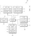
- FIG. 1is a block diagram showing a nucleic acid analysis apparatus using a cartridge according to an embodiment of the present invention.
- FIG. 2 and 3are schematic views showing the nucleic acid analysis apparatus of FIG.
- FIG. 4is an enlarged schematic view of portion A of FIG. 2.
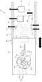
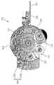
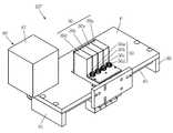
- FIG. 5is a perspective view showing the nucleic acid extraction cartridge of FIG.
- FIG. 6is a plan view illustrating the air valve module of FIG. 5.
- FIG. 7 and 8are plan views illustrating the liquid valve module of FIG. 5.
- FIGS. 9 and 10are views illustrating a state in which a liquid valve driving unit is installed in a valve of the liquid valve module.
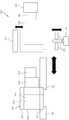
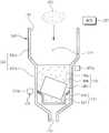
- FIG. 11shows the pretreatment chamber of FIG. 5.
- FIG. 12is a flowchart illustrating a nucleic acid extraction method using a nucleic acid extraction cartridge according to an embodiment of the present invention.
- FIG. 13is a detailed flowchart of the preprocessing step of FIG. 12.
- 14 to 16are diagrams illustrating each detailed step according to the preprocessing step of FIG. 13.
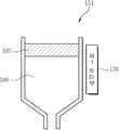
- FIG. 17is a view showing a separation chamber according to the second purification step of FIG. 12.
- FIG. 18is a detailed flowchart of the tertiary purification step of FIG. 12.
- FIG. 20is a block diagram illustrating a fluorescence detector of FIG. 4.
- FIG. 21is a perspective view illustrating the fluorescence detector of FIG. 20.
- FIG. 22is a bottom perspective view of FIG. 21.
- FIG. 23is a plan view of FIG. 21.
- FIG. 24is a cross-sectional view taken along the line A-A of FIG.
- FIG. 25is a view illustrating an optical path of the light emitting part of FIG. 23.
- FIG. 26is a plan view illustrating a filter module of the moving filter unit of FIG. 21.
- FIG. 27is a side view illustrating a filter module of the moving filter unit of FIG. 26.
- 28 to 34are views illustrating a fluorescence detection process using the fluorescence detection unit.
- first and secondare used to describe various components, and are used only to distinguish one component from another component, and to limit the components. Not used.
- the second componentmay be referred to as the first component, and similarly, the first component may also be referred to as the second component.
- a componentwhen referred to as being "connected” or “connected” to another component, it means that it may be connected or connected logically or physically. In other words, although a component may be directly connected or connected to other components, it should be understood that other components may exist in the middle, and may be connected or connected indirectly.
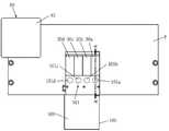
- FIG. 1is a block diagram showing a nucleic acid analysis apparatus using a cartridge according to an embodiment of the present invention.
- 2 and 3are schematic views showing the nucleic acid analysis apparatus of FIG. 4 is an enlarged schematic view of portion A of FIG. 2.
- 5is a perspective view showing the nucleic acid extracting cartridge of FIG.
- the nucleic acid analysis apparatus 100is a point of care testing (POCT) device using the nucleic acid extracting cartridge 110, the cartridge 110 as a cartridge 110.
- POCTpoint of care testing
- Pretreatment, nucleic acid extraction / purification, nucleic acid amplification and fluorescence detectionare performed in batches on the sample to be introduced.
- the nucleic acid analysis apparatus 100includes a stage 192 on which the cartridge 110 is mounted, a nucleic acid extracting unit 195, a fluorescence detecting unit 197, and a controller 178.
- the cartridge 110is mounted to the stage 192.
- the cartridge 110includes a plurality of chambers for extracting nucleic acid from a sample, including a pretreatment chamber 140 in which the sample to be injected is crushed to homogenize, destroy cells, and purify.
- the nucleic acid extracting unit 195performs nucleic acid extraction and nucleic acid amplification through crushing, cell disruption, and purification of the sample injected into the cartridge 110.
- the fluorescence detector 197optically detects fluorescence of a plurality of wavelength bands according to amplification of nucleic acids on the cartridge 110.
- the controller 178controls driving of the stage 192, the nucleic acid extracting unit 195, and the fluorescence detecting unit 197, and extracts nucleic acids through crushing, cell disruption, and purification of the sample introduced into the cartridge 110. And fluorescence detection is carried out collectively.
- the nucleic acid extractor 195may include magnetic force applying units 173 and 175, a pump driving unit 177, a heater unit 176 and 179, and a valve driving unit 172 and 174.
- the heater parts 176 and 179may include a first heater part 176 and a second heater part 179.
- the valve driver 172, 174may include an air valve driver 172 and a liquid valve driver 174.
- the fluorescence detector 197may include a plurality of light emitting units 30, a plurality of light receiving units 50, and a moving filter unit 60.
- the nucleic acid analysis apparatus 100may further include a stage transfer unit 191.
- the stage 192has a cartridge 110 mounted thereon. With the cartridge 110 mounted on the stage 192, pretreatment, nucleic acid extraction, and nucleic acid amplification of the sample are performed in a batch.
- the stage 192has a connection hole 193 formed in the portion where the cartridge 110 is mounted.
- the pump driver 177 and the liquid valve driver 174are connected to the cartridge 110 mounted on the stage 192 through the connection hole 193. That is, the pump driver 177 is connected to the pump 137 of the cartridge 110 through the connection hole 193.
- the liquid valve driver 174is connected to the liquid valve module 135 of the cartridge 110 through the connection hole 193.
- the stage transfer unit 191loads the stage 192 into a working area in which the magnetic force applying units 173 and 175, the pump driving unit 177, the heater units 176 and 179, the valve driving units 172 and 174, and the fluorescence detection unit 197 are installed. Unload from. That is, when the cartridge 110 into which the sample is inserted is mounted on the stage 192, the stage transfer unit 191 transfers the stage 192 to the work area under the control of the controller 178 to load the cartridge 110. When the pretreatment, nucleic acid extraction, nucleic acid amplification, and fluorescence detection for the sample loaded into the cartridge 110 loaded into the working area is completed, the stage transfer unit 191 moves the stage 192 out of the working area to freeze the cartridge 110. Load.
- the stage transfer unit 191may include a stepping motor 191a for transferring the stage 192 and a transfer rail 191b for guiding the transfer of the stage 192 according to the driving of the stepping motor 191a.
- the magnetic force applying units 173 and 175, the pump driving unit 177, the heater units 176 and 179, the valve driving units 172 and 174, and the fluorescence detection unit 197are provided to be movable.
- the controller 178may also be installed together in the work area.
- the cartridge 110is a sample is inserted into the cell disruption, nucleic acid extraction / purification, nucleic acid amplification and fluorescence detection is carried out in a batch, it is used for one time.
- Samplesare biosamples that require pretreatment, such as stool, tissue, sputum. Other samples may be blood, urine, saliva, semen, spinal fluid, mucus, and the like.
- the cartridge 110includes a chamber module 131, an air valve module 133, and a liquid valve module 135.
- the chamber module 131includes a plurality of chambers for extracting nucleic acids from a sample, including a pretreatment chamber 140 in which a sample to be injected is crushed to homogenize, destroy cells, and purify.
- the air valve module 133is installed above the chamber module 131, and controls the pressure to move the fluid between the plurality of chambers.
- the liquid valve module 135is installed below the chamber module 131 and moves the fluid between the plurality of chambers.
- the plurality of chambers of the chamber module 131may be a pretreatment chamber 140, a separation chamber 151, a cleaning chamber 153, an elution chamber 157, a reaction chamber 155, a nucleic acid amplification reagent chamber 159, or a nucleic acid.
- the chamber module 131may further include a waste chamber 158 in which used reagents and debris are discarded.
- the chamber module 131may have a pump 137 that applies air pressure necessary for driving the air valve module 133 to a central portion thereof.
- the chamber module 131has a pretreatment chamber 140, a separation chamber 151, a cleaning chamber 153, a reaction chamber 155, and an elution chamber 157 around the pump 137.
- the nucleic acid amplification reagent chamber 159 and the nucleic acid amplification chamber 161may be installed.
- the nucleic acid amplification reagent chamber 159 and the nucleic acid amplification chamber 161may be disposed between the pretreatment chamber 140 and the elution chamber 157, and may protrude outward with respect to the plurality of other chambers.
- the waste chamber 158may be disposed between the other chambers and the pump 137.
- the pump 137is installed at the center portion of the chamber module 131, and supplies the necessary pressure to the plurality of chambers while moving up and down by the pump driver 177.
- the chamber module 131has a pump hole 139 formed at a central portion thereof to transfer the necessary pressure to the plurality of chambers while the pump 137 moves up and down.
- the air pressuremay be delivered to the plurality of chambers by the rise of the pump 137.
- the magnetic force applying units 173 and 175apply magnetic force to the cartridge 110 to perform homogenization, cell disruption, and nucleic acid separation by crushing the sample in the cartridge 110.
- the magnetic force applying units 173 and 175include a first magnetic force applying unit 173 and a second magnetic force applying unit 175.
- the first magnetic force applying unit 173is installed outside the pretreatment chamber 140 to intermittently apply magnetic force to the pretreatment chamber 140 to move the magnetic block contained in the pretreatment chamber 140 to the pretreatment chamber 140.
- the pretreatment process for the sample to be madeis smoothly performed.
- a plurality of first magnetic force applying units 173may be installed in different positions in order to smoothly move the magnet block contained in the pretreatment chamber 140 in the pretreatment chamber 140.
- the first magnetic force applying unit 173may include a 1-1 magnetic force applying unit 173a and a 1-2 second magnetic force applying unit 173b.
- the second magnetic force applying unit 175is installed outside the reaction chamber 155 to apply magnetic force to the reaction chamber 155 to fix or release the magnetic particles contained in the reaction chamber 155 to clean and elute the nucleic acid. Make the process smooth.
- the magnetic force applying units 173 and 175are installed to be movable to the work area. That is, the magnetic force applying units 173 and 175 are spaced apart from the cartridge 110 when the cartridge 110 is loaded into the working area so as not to physically interfere with the cartridge 110 loaded into the working area. When the cartridge 110 is finished loading into the work area, the magnetic force applying units 173 and 175 move closer to the pretreatment chamber 140 and the reaction chamber 155. When nucleic acid extraction, nucleic acid amplification, and fluorescence detection using the cartridge 110 are completed, the magnetic force applying units 173 and 175 may include the pretreatment chamber 140 and the reaction chamber 155 so that the cartridge 110 may be unloaded in the working area. Spaced apart from
- the heaters 176 and 179include a first heater 176 and a second heater 179.
- the first heater unit 176is installed outside the separation chamber 151, so that the separation process for the first purification liquid supplied from the pretreatment chamber 140 may be performed by applying heat to the separation chamber 151. do.
- the second heater unit 179is installed outside the nucleic acid amplification chamber 161, and the heat is applied to the nucleic acid amplification chamber 161 to facilitate the nucleic acid amplification reaction.
- the heaters 176 and 179may be installed to be movable to the work area. That is, the heaters 176 and 179 are spaced apart from the cartridge 110 when the cartridge 110 is loaded into the work area so as not to physically interfere with the cartridge 110 loaded into the work area.
- the heaters 176 and 179move in close proximity to the separation chamber 151, the reaction chamber 155 and the nucleic acid amplification chamber 161.
- the heater parts 176 and 179are separated from the chamber 151, the reaction chamber 155, and the unloading cartridge 110 in the working area. Spaced apart from the nucleic acid amplification chamber 161.
- the pump driver 177applies pressure necessary for fluid movement between the chambers of the cartridge 110. That is, the pump driving unit 177 drives the pump 137 to apply air pressure to the air valve module 133 of the cartridge 110.
- the pump driving unit 177is installed at the lower portion of the work area and is movably installed at the lower portion of the cartridge 110 moved to the working area. For example, a stepping motor may be used as the pump driver 177.
- the valve driver 172, 174includes an air valve driver 172 and a liquid valve driver 174.
- the air valve driver 172opens and closes the valves of the air valve module 133.
- the air valve driver 172is installed at an upper portion of the work area and is connected to the air valve module 133 of the cartridge 110 moved to the work area.
- the air valve driver 172is installed to be movable above the cartridge 110 moved to the work area.
- the air valve driving unit 172includes an electromagnet corresponding to the number of valves of the air valve module 133.
- the liquid valve driver 174opens and closes the valves of the liquid valve module 135.
- the liquid valve driver 174is installed at the lower portion of the work area and is connected to the liquid valve module 135 of the cartridge 110 through the connection hole 193 of the stage 192 moved to the work area.
- the liquid valve driver 174is movably installed under the cartridge 110 moved to the work area.
- the liquid valve driver 174includes an electromagnet corresponding to the number of valves of the liquid valve module 135. The opening and closing of the valve of the liquid valve module 135 by the electromagnet of the liquid valve driving unit 174 will be described later.
- the controller 178is a microprocessor that performs overall control operations of the nucleic acid analysis apparatus 100.
- the controller 178controls the driving of the stage transfer unit 191, the nucleic acid extracting unit 195, and the fluorescence detection unit 197 to feed the cartridge 110.
- Pretreatment, nucleic acid extraction, nucleic acid amplification and fluorescence detection for the sample to be controlledare controlled in a batch.
- the driving method for nucleic acid extraction, nucleic acid amplification, and fluorescence detection of the nucleic acid analysis apparatus 100 according to the present embodimentis as follows.
- the stage 192is separated from the work area by the stage transfer unit 191 so that the cartridge 110 into which the sample is first introduced can be mounted on the stage 192.
- the magnetic force applying units 173 and 175, the heater units 176 and 179, the pump driving unit 177, the valve driving units 172 and 174, and the fluorescence detection unit 197 in the work areaalso prevent mechanical interference with the cartridge 110 to be transferred to the work area. It is separated from the work area.
- the stage transfer unit 191is a cartridge 110 mounted in the stage 192. Load into the work area.
- the magnetic force applying units 173 and 175, the heater units 176 and 179, the pump driving unit 177, the valve driving units 172 and 174, and the fluorescence detection unitmoves to the work area and is connected to the loaded cartridge 110.
- the first magnetic force applying unit 173is close to the pretreatment chamber 140 of the cartridge 110.
- the second magnetic force applying unit 175is close to the reaction chamber 155.
- the first heater unit 176is close to the separation chamber 151.
- the second heater unit 179is close to one surface of the nucleic acid amplification chamber 161.
- the pump driver 177is connected to the pump 137 of the cartridge 110.
- the valve drives 172, 174are connected to the air valve module 133 and the liquid valve module 135.
- the fluorescence detector 197is close to the other surface of the nucleic acid amplification chamber 161.
- the controller 178controls the driving of the magnetic force applying units 173 and 175, the heater units 176 and 179, the pump driving unit 177, the valve driving units 172 and 174, and the fluorescence detection unit 197 to control the sample input to the cartridge 110.
- Pretreatment, nucleic acid extraction, nucleic acid amplification and fluorescence detectionare performed in batches. Pretreatment, nucleic acid extraction, nucleic acid amplification and fluorescence detection for the sample introduced into the cartridge 110 will be described later.
- the controller 178unloads the cartridge 110 into the work area. That is, the controller 178 separates the magnetic force applying units 173 and 175, the heater units 176 and 179, the pump driving unit 177, the valve driving units 172 and 174, and the fluorescence detection unit 197 from the cartridge 110 and moves them out of the work area.
- the controller 178drives the stage transfer unit 191 to unload the cartridge 110 of the stage 192 out of the working area.
- the nucleic acid analyzing apparatus 100since the nucleic acid analyzing apparatus 100 according to the present embodiment includes the nucleic acid extracting unit 195 and the fluorescence detecting unit 197, the nucleic acid amplification chamber 161 of the cartridge 110 on the stage 192 after nucleic acid amplification. ) May proceed together with the fluorescence detection process. That is, after collectively completing nucleic acid extraction, amplification and detection, the controller 178 unloads the cartridge 110 from the work area.
- FIGS. 5 to 11The cartridge 110 according to the present embodiment will be described with reference to FIGS. 5 to 11 as follows.
- 6is a plan view illustrating the air valve module 133 of FIG. 5.
- 7 and 8are top views illustrating the liquid valve module 135 of FIG. 5.
- 9 and 10are views illustrating a state in which the electromagnet 174a of the liquid valve driving unit 174 is installed in the valve 13 of the liquid valve module 135.
- FIG. 11is a diagram illustrating the pretreatment chamber 140 of FIG. 5.
- the cartridge 110includes the chamber module 131, the air valve module 133, and the liquid valve module 137, as described above.
- the chamber module 131includes the pretreatment chamber 140, the separation chamber 151, the cleaning chamber 153, the elution chamber 157, the reaction chamber 155, the nucleic acid amplification reagent chamber 159, and the nucleic acid amplification chamber 161. And a waste chamber 158.
- the pretreatment chamber 140, the separation chamber 151, the cleaning chamber 153, the reaction chamber 155, and the elution chamber 157may be sequentially disposed around the pump 137 around the pump 137.
- the waste chamber 158may be disposed between the other chambers and the pump 137.
- the pretreatment chamber 140contains the pretreatment member 149 including the pretreatment liquid 149a, the magnetic block 149b or the cell disrupting particles 149c, and contains nucleic acid after crushing and cell destruction on the sample to be introduced.
- the primary purification liquidis discharged to the separation chamber 151.
- the pretreatment chamber 140may include a chamber body 141 and a cup filter 145, and may contain the pretreatment member 149 in the chamber body 141 on the cup filter 145.
- the chamber main body 141is formed with an internal space 144 through which the injected sample is crushed to homogenize and destroy cells.
- the cup filter 145is installed at the lower portion of the inner space 144 and filters and passes the primary purification liquid containing the nucleic acid flowing out of the cells.
- the chamber body 141includes an upper body 141a and a lower body 141b.
- the upper body 141ahas a pretreatment member 149 and an inlet 142 into which the sample is inserted.
- the lower main body 141bis connected to the lower part of the upper main body 141a and has a smaller inner diameter than the upper main body 141a.
- the lower body 141bhas a discharge port 143 through which the primary purification liquid is discharged, and a cup filter 145 is coupled therein.
- the pretreatment member 149includes the pretreatment liquid 149a, the magnetic block 149b or the cell disrupting particles 149c as described above.
- the pretreatment liquid 149acan be used without limitation as long as it is a general pretreatment liquid used for molecular diagnosis.
- 0.01 to 0.1 parts by weight of the samplemay be added to 100 parts by weight of the pretreatment liquid 149a. If the sample is added below 0.01 parts by weight, the yield may be too low to be inefficient. If the sample is added in excess of 0.1 parts by weight, the homogenization may not be smooth. Therefore, the amount of the pretreatment liquid 149a and the sample can be adjusted within the aforementioned range.
- the cell disrupting particles 149cmay be glass beads used as nonmagnetic materials.
- the magnet block 149b and the cell disrupting particle 149care pulverized and homogenized while moving in the pretreatment liquid 149a by an intermittently applied magnetic force. Furthermore, the cell disrupting particles 149c move in conjunction with the movement of the magnetic block 149b to destroy cells contained in the sample so that the nucleic acid flows out.
- the cell disrupting particles 149cuse particles larger than the pores formed in the cup filter 145 so as not to pass through the cup filter 145 during the first purification process.
- the particle size of the cell disrupting particles 149cmay be 50 ⁇ m or more.
- the magnet block 149bmay have a size that may be located inside the lower body 141b.
- the pretreatment member 149is contained in the internal space 144 of the chamber body 141 above the cup filter 145.
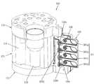
- the cup filter 145includes a filter part 146 and a cup part 147.
- the filter unit 146is formed to be inclined downward in the portion coupled to the inside of the chamber body 141 and filters and passes the primary purification liquid containing the nucleic acid flowing out of the cell.
- the cup part 147is connected to the filter part 146, and the remaining debris is filtered and precipitated.
- the cup part 147may be located at the center of the inner space 144 of the chamber body 141.
- the filter part 146extends upward from the upper end of the cup part 147 and is coupled to the inside of the chamber body 141.
- the filter unit 146is formed of a funnel-shaped inclined surface, and the pores for passing the primary purification liquid is formed.
- the filter part 146Since the filter part 146 is formed in the inclined surface toward the cup part 147, the debris which has not passed through the filter part 146 moves on the inclined surface of the filter part 146 into the cup part 147 to settle. Therefore, in the process of primary purification, debris that has not passed through the filter unit 146 may be prevented from delaying or preventing primary purification by blocking pores of the filter unit 146.
- the primary purification liquidcontains nucleic acid, pretreatment liquid 149a, and debris.
- the separation chamber 151receives the first purification liquid from the pretreatment chamber 140 and performs the second purification using heat.
- This separation chamber 151is disposed adjacent to the pretreatment chamber 140 and contains the separation reagent.
- the separation chamber 151receives the primary purification liquid from the pretreatment chamber 140 and performs phase separation with respect to the primary purification liquid using heat applied from the first heater unit 176.
- the separation chamber 151discharges the secondary purification liquid containing nucleic acid to the reaction chamber 155 by phase separation.
- the separating reagentaggregates the protein when heat is applied. Therefore, when heat is applied after the primary purification liquid is supplied to the separation chamber 151 containing the separation reagent, the debris containing the protein component aggregates and floats up, and the secondary purification liquid is positioned below.
- the separation chamber 151discharges a portion of the secondary purification liquid located under the aggregated debris to the reaction chamber 155.
- the cleaning chamber 153is disposed between the separation chamber 151 and the reaction chamber 155 and contains a cleaning liquid for cleaning the secondary purification liquid, and the third purification is performed by supplying the cleaning liquid to the reaction chamber 155.
- the cleaning chamber 153may include a first cleaning chamber 153a containing a first cleaning liquid and a second cleaning chamber 153b containing a second cleaning liquid.
- the first cleaning liquidmay include ethanol and water.
- the second cleaning liquidmay be ethanol.
- the tertiary purificationmay be performed by first washing with the first washing liquid and second washing with the second washing liquid.
- the reason why the washing is performed in a plurality of stepsis to remove the remaining debris or reagents while leaving only the nucleic acid in the secondary purification liquid.
- the reason why water was used together with ethanol in the first cleaning solutionis as follows.
- the nucleic acid contained in the secondary purification liquidis adsorbed to the magnetic particles contained in the reaction chamber 155.
- residuesmay be adsorbed on the magnetic particles together with the nucleic acid, or nucleic acids may be weakly adsorbed.
- Waterhas the property of separating the material adsorbed to the magnetic particles from the magnetic particles. Therefore, by using some water together with ethanol as the first cleaning liquid, it is possible to separate the residue adsorbed on the magnetic particles or the nucleic acid adsorbed weakly on the adsorption strength.
- the second nucleic acidAfter washing with the first washing liquid, the second nucleic acid can be separated from the secondary purification liquid by washing again with the second washing liquid.
- the isolated nucleic acidis adsorbed to the magnetic particles.
- the elution chamber 157is disposed between the reaction chamber 155 and the pretreatment chamber 140 and contains the eluate.
- the elution chamber 157supplies the eluate to the reaction chamber 155.
- Watermay be used as the eluate.
- the eluateseparates the nucleic acid adsorbed on the magnetic particles.
- the reaction chamber 155is disposed between the cleaning chamber 153 and the elution chamber 157 and performs tertiary purification and nucleic acid separation (extraction). This reaction chamber 155 contains a binding reagent and magnetic particles.
- the reaction chamber 155secondary purification of the secondary purification liquid supplied from the separation chamber 151 is performed to the reaction chamber 155. That is, when the secondary purification liquid is supplied from the separation chamber 151 to the reaction chamber 155, the magnetic particles selectively adsorb the nucleic acid contained in the secondary purification liquid.
- the reaction chamber 155discharges the binding reagent and the secondary purification liquid to the waste chamber 158 except for the magnetic particles to which the nucleic acid is adsorbed.
- the reaction chamber 155receives the cleaning liquid from the cleaning chamber 153, cleans the magnetic particles having the nucleic acid adsorbed therein, and discharges the magnetic particles to the waste chamber 158. In this case, before discharging the solution of the reaction chamber 155 to the waste chamber 158, the second magnetic force applying unit 175 applies magnetic force to the reaction chamber 155 to fix the magnetic particles to which the nucleic acid is adsorbed.
- the reaction chamber 155receives the eluate from the elution chamber 157 to separate the nucleic acid from the magnetic particles, and then discharges the eluate containing the nucleic acid to the nucleic acid amplification reagent chamber 159.
- the second magnetic force applying unit 175applies magnetic force to the reaction chamber 155 to fix the magnetic particles from which the nucleic acid is separated.
- the nucleic acid amplification reagent chamber 159contains a nucleic acid amplification reagent.
- the nucleic acid amplification reagent chamber 159receives the eluate containing the nucleic acid from the reaction chamber 155 and mixes with the nucleic acid amplification reagent to generate a nucleic acid amplification mixture.
- the nucleic acid amplification reagent chamber 159discharges the generated nucleic acid amplification mixture to the nucleic acid amplification chamber 161.
- the nucleic acid amplification reagentmay be provided in the nucleic acid amplification reagent chamber 159 in lyophilized form.
- Nucleic acid amplification reagent chamber 159may be provided in plurality.
- the nucleic acid amplification reagent chamber 159may include first to fourth nucleic acid amplification reagent chambers 159a, 159b, 159c, and 159d.
- the nucleic acid amplification chamber 161receives a nucleic acid amplification mixture from the nucleic acid amplification reagent chamber 159 and then performs a nucleic acid amplification reaction using heat applied from the second heater unit 179.
- Nucleic acid amplification chamber 161may be provided in plurality. The plurality of nucleic acid amplification chambers 161 form the nucleic acid amplification module 160.
- the nucleic acid amplification chamber 161may include first to fourth nucleic acid amplification chambers 161a, 161b, 161c, and 161d.
- the air valve module 133opens and closes the application of air pressure required for fluid movement between the plurality of chambers.
- the air valve module 133includes a plurality of valves 1 to 12 for opening and closing the application of air pressure, and an air flow path connecting the plurality of valves 1 to 12 and the pump 137.
- the plurality of valves 1 to 12may be electromagnet valves.
- the air valve module 133may include first to twelfth valves 1 to 12.
- the first valve 1opens and closes the application of air pressure to the pretreatment chamber 140.
- the second and eighth valves 2, 8open and close the application of air pressure to the separation chamber 151.
- the third and ninth valves 3 and 9open and close the application of air pressure to the first cleaning chamber 153a.
- the fourth and tenth valves 4 and 10open and close the application of air pressure to the second cleaning chamber 153b.
- the fifth and eleventh valves 5 and 11open and close the application of air pressure to the reaction chamber 155.
- the sixth and twelfth valves 6 and 12open and close the application of air pressure to the elution chamber 157.
- the seventh valve 7opens and closes the application of air pressure to the nucleic acid amplification reagent chamber 159.
- the liquid valve module 135opens and closes fluid movement between the plurality of chambers, as shown in FIGS. 7 and 8.
- the liquid valve module 135includes a plurality of valves 13 to 28 for opening and closing fluid movement between the plurality of chambers, and a liquid flow path for guiding fluid movement between the plurality of chambers.
- the plurality of valves 13 to 28may be electromagnet valves.
- the liquid valve module 135may include thirteenth to twenty eighth valves 13 to 28.
- the thirteenth valve 13is installed in the pretreatment chamber 140.
- the fourteenth valve 14is installed in the separation chamber 151.
- the fifteenth valve 15is installed in the first cleaning chamber 153a.
- the sixteenth valve 16is installed in the second cleaning chamber 153b.
- the seventeenth valve 17is installed in the fluid flow path between the reaction chamber 155 and the waste chamber 158.
- An eighteenth valve 18is installed in the reaction chamber 155.
- the nineteenth valve 19is provided with a liquid flow path between the reaction chamber 155 and the nucleic acid amplification reagent chamber 159.
- the twentieth valve 20is installed in the elution chamber 157.
- the twenty-first to twenty-eighth valves 21 to 28are installed in the plurality of nucleic acid amplification reagent chambers 159a, 159b, 159c, and 159d. At this time, there are four nucleic acid amplification reagent chambers 159, and two valves 21 to 28 are respectively installed.
- Fluid movement between the plurality of chambers according to the nucleic acid extraction processis performed by the interlocking of the air valve module 133 and the liquid valve module 135. Detailed description will be made in the nucleic acid extraction method.
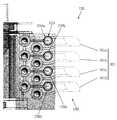
- FIGS. 9 and 10are views illustrating a state in which the electromagnet 174a of the liquid valve driving unit 174 is installed in the valve 13 of the liquid valve module 135.
- 9 and 10illustrate a thirteenth valve 13 installed in the pretreatment chamber 140. 9 shows a state where the thirteenth valve 13 is closed, and FIG. 10 shows a state where the thirteenth valve 13 is opened.
- valves of the liquid valve module 135have the same structure, the following description will be given with reference to FIGS. 9 and 10 with reference to the thirteenth valve 13.
- the thirteenth valve 13includes a valve structure 411 and a metal plate 421.
- the valve structure 411opens and closes the flow paths 143a and 151a of the chambers 140 and 51 which are elastically connected.
- the metal plate 421is installed below the valve structure 411, and moves the valve structure 411 up and down by opening or closing the flow path by applying magnetic force through the liquid valve driving unit 174.
- the thirteenth valve 13opens and closes the connection between the inlet flow passage 143a connected to the pretreatment chamber 140 and the outlet flow passage 151a connected to the separation chamber 151. That is, the thirteenth valve 13 connects to or disconnects from the outlet passage 151a of the separation chamber 151 through opening and closing of the inlet passage 143a.
- the valve structure 411includes a tubular valve column 413, a valve body 417 and a membrane 415.
- the valve body 417is spaced apart from the inner wall of the valve column 413, and is formed at the center of the valve column 413, and a valve dome 419 for opening and closing the inlet flow path 143a is formed at an upper portion thereof. 421 is installed.
- the membrane 415connects the inner wall of the valve column 413 and the valve body 417, and moves the valve body 417 up and down elastically in the valve column 413 to open and close the inlet flow path 143a. It regulates the flow of fluid between the two chambers (140, 51).
- valve column 413supports the valve structure 411 and allows the thirteenth valve 13 to be mounted to the cartridge 110.
- the valve column 413supports the valve body 417 via a membrane 415 connected to the inner wall.
- the valve body 417is installed in a shape suspended from the inside of the valve column 413 via the membrane 415.
- the metal plate 421is attached to the lower end of the valve body 417.
- the valve dome 419 on the upper end of the valve body 417protrudes to the upper end of the valve column 413 when no external force such as magnetic force is applied, and always opens the inlet flow passage 43a in the state that no external force is applied. It performs the function of normally closed (NC).
- the thirteenth valve 13will be described in detail as follows.
- a thirteenth valve 13is disposed between the inlet flow passage 143a and the outlet flow passage 151a to control the flow of the fluid.
- the thirteenth valve 13includes a valve structure 411 made of an elastic body and a metal plate 421.
- the valve structure 411is positioned in the connection space 423 to which the inlet flow passage 143a and the outlet flow passage 151a are connected, and are in contact with the end of the inlet flow passage 143a.
- valve structure 411Since the valve structure 411 is made of a material having a certain elasticity, the valve structure 411 may be compressed at a portion in contact with the inlet flow passage 143a and thus block the inlet flow passage 143a. At this time, the outlet flow path 151a is exposed to the connection space 423 so that it is physically separated from the inlet flow path 143a. Therefore, in this case, since the flow path through which the fluid can move from the pretreatment chamber 140 to the separation chamber 151 is blocked, the flow path is closed by the thirteenth valve 13. Since the valve structure 411 is an elastic body, the valve structure 411 continues to be in contact with the inlet flow passage 143a until it is pulled down by applying force from the outside, and thus acts as an NC valve maintaining the closed state.
- valve structure 411which is in contact with the inlet flow passage 143a must be pulled down.
- the metal plate 421 at the bottom of the valve structure 411is provided. Use the characteristic of moving by magnetic force.
- the electromagnet 174a of the liquid valve drive unit 174is disposed below the metal plate 421 at regular intervals.
- a strong magnetic fieldis generated at the upper end of the electromagnet 174a, and the metal plate 421 attached under the valve body 417 may be pulled to the upper end of the electromagnet 174a. Will be.
- the metal plate 421is moved and attached to the upper end of the electromagnet 174a positioned below.
- the valve body 417 connected to the metal plate 421moves downward in cooperation with the metal plate 421 to open the inlet flow passage 143a.
- the open inlet flow passage 143ais connected to the outlet flow passage 151a through the connection space 423, whereby the thirteenth valve 13 is changed into an open state through which the fluid can flow.
- the thirteenth valve 13maintains an open state in which fluid flows while power is applied to the electromagnet 174a.
- the applied poweris cut off, since the external force pulling the metal plate 421 is removed, it is returned to its original position with respect to the valve body 417 by the elastic force accumulated in the membrane 415. That is, the valve body 417 rises to block the inlet flow passage 143a.
- the membrane 415is preferably formed to a thickness such that the valve body 417 can be elastically changed according to the on / off of the electromagnet 174a. That is, the thicker the membrane 415 requires more force to move the valve body 417, so that the degree of impact received while moving and storing the cartridge 110 containing the fluid is expected to
- the valve body 417should be designed to open when the fluid is pushed with greater force. Therefore, when it is necessary to block the flow of the fluid with a strong force, the thickness of the membrane 415 should be made thick, and if it is a situation where only a weak force may be used, the thickness of the membrane 415 may be made thin.
- the thickness of the membrane 415increases, more force is required to switch from the NC state to the open state, and thus, a force-sensitive electromagnet 174a is required, so that the thickness of the membrane 415 is appropriate to the environment in which the valve is used. It is necessary.
- the membrane 415since the maximum pressure for maintaining the closed state is changed according to the elasticity of the valve structure 411, it is also necessary to select a material suitable for the pressure range to be used.
- the membrane 415may be manufactured to have a thickness of 100 to 1,000 ⁇ m.
- a metal plate 421In order to drive the valve body 417 by the electromagnet 174a, a metal plate 421 must be attached to the lower end of the valve body 417, which is used to inject the metal plate 421 when injection molding the valve structure 411 which is an elastic body. Can be inserted and produced.
- the metal plate 421may be made of a material that can be attached to the electromagnet 174a, for example, iron. The larger the area and the thicker the metal plate 421 is, the better it may be attached to the electromagnet 174a.
- ironwhile using iron as a material of the metal plate 421, it is possible to use a soft iron that can minimize the influence of the magnetic force remaining when the power of the electromagnet (174a) is cut off.
- FIG. 12is a flowchart illustrating a nucleic acid analysis method using a nucleic acid extracting cartridge according to an embodiment of the present invention.
- Nucleic acid analysis methodis a pre-treatment step (S10), including the crushing, cell destruction and primary purification for the sample, the second purification step (S20) using the phase separation by heat, the third purification using the cleaning solution and magnetic particles Step (S30), nucleic acid separation step (S50) using the eluate and magnetic particles, nucleic acid amplification mixture generation step (S60), nucleic acid amplification chamber injection step (S70), nucleic acid amplification reaction step (S80) and fluorescence detection step (S90) It includes.
- the pretreatment processincluding crushing, cell destruction, and primary purification of the sample is performed in a batch in the pretreatment chamber, and the primary purification liquid is discharged to the separation chamber.
- FIG. 13is a detailed flowchart of the preprocessing step of FIG. 12.
- 14 to 16are diagrams illustrating each detailed step according to the preprocessing step of FIG. 13.
- a pretreatment chamber 140 containing a sample 181 and a pretreatment member 149is prepared.
- the sample 181may be introduced.
- the sample 181may be introduced into the pretreatment chamber 140, and then the pretreatment member 149 may be introduced.
- the sample 181 and the pretreatment member 149may be simultaneously introduced into the pretreatment chamber 140.
- step S13homogenization and cell destruction are performed on the sample in step S13. That is, the first-first magnetic force applying unit 173a and the first-second magnetic force applying unit 173b intermittently apply magnetic force to the pretreatment chamber 140 to move the magnet block 149b to grind and homogenize the sample.
- the magnetic blocks applied to the first-first magnetic force applying unit 173a and the first-second magnetic force applying unit 173bare switched to move the magnet block 149b in the pretreatment liquid 149a.
- the cell disrupting particles 149cmove in conjunction with the movement of the magnet block 149b to destroy cells included in the sample so that the nucleic acid flows out.
- heatmay be additionally applied so that homogenization and cell destruction of the sample can be performed more quickly.
- step S15the first purification liquid 183 is filtered and discharged to the separation chamber.
- the primary purification liquid containing the nucleic acidflowed out of the cell by the cell destruction of the sample by applying pressure through the pump 137 so that the pretreatment liquid passes through the cup filter 145 in the lower part of the pretreatment chamber 140. Filter (183).
- Reference numeral 185denotes a precipitate formed of debris that has moved to the cup portion 147.
- the 1st valve 1, the 8th valve 8, and the 13th valve 13are opened sequentially.
- the pump 137is operated to apply pressure to the pretreatment chamber 140 to move the primary purification liquid to the separation chamber 151.
- the first valve 1, the eighth valve 18, and the thirteenth valve 13are sequentially closed. Then, the operation of the pump 137 is turned off and the vent is performed.
- step S20when the first purification liquid pretreated in step S20 is introduced into the separation chamber 151, as shown in FIG. 17, secondary purification using phase separation by heat is performed in the separation chamber 151, and the second purification is performed.
- the first heater 176may apply heat of 50 to 80 ° C. for 3 to 30 minutes to the separation chamber 151.
- the debris contained in the primary purification liquidis agglomerated and floated up in the form of a float 187, and the relatively clean secondary purification liquid 186 is positioned below the float 187. do.
- the second valve 2, the eighteenth valve 18, the eleventh valve 11, and the fourteenth valve 14are sequentially opened.
- the pump 137is operated to apply pressure to the separation chamber 151 to move the secondary purification liquid to the reaction chamber 155.
- the 2nd valve 2, the 18th valve 18, and the 11th valve 11are closed sequentially. 2 remaining in the liquid flow path connecting the separation chamber 151 and the separation chamber 151 and the reaction chamber 155 by opening the second valve 2, the fourteenth valve 14, and the seventeenth valve 17.
- the primary purification liquidis discharged to the waste chamber 158.
- the operation of the pump 37is turned off and venting is performed. And the 2nd valve 2, the 14th valve 14, and the 17th valve 17 are closed.
- the secondary purification liquidis added to the reaction chamber 155 in step S30, the third purification using the cleaning liquid and magnetic particles is performed in the reaction chamber 155.
- the washing according to the tertiary purificationcan be performed multiple times. In this embodiment, an example in which two washings are performed is disclosed.
- FIG. 18is a detailed flowchart of the tertiary purification step of FIG. 12.
- step S31the second purification liquid is supplied from the separation chamber 151 to the reaction chamber 155.
- the magnetic particles contained in the reaction chamber 155selectively adsorb the nucleic acid contained in the secondary purification liquid.
- the magnetic particlesmay be applied by switching the magnetic force to the reaction chamber 155 to more effectively adsorb the nucleic acid.
- a magnetic forceis applied to the reaction chamber 155 to fix the magnetic particles to which the nucleic acid is adsorbed.
- the remaining solution except the magnetic particles to which the nucleic acid is adsorbedmay be discharged from the reaction chamber 155 to the waste chamber 158.
- the magnetic forceis applied to the reaction chamber 155 by the second magnetic force applying unit 175.
- step S35 to step S45the reaction chamber 155 is supplied with a cleaning liquid from the cleaning chamber 151 to clean the magnetic particles to which the nucleic acid is adsorbed, and then discharges them to the waste chamber 158.
- a cleaning liquidfrom the cleaning chamber 151 to clean the magnetic particles to which the nucleic acid is adsorbed, and then discharges them to the waste chamber 158.
- the magnetic forceis switched to perform the first cleaning.
- magnetic forceis applied to the reaction chamber 155 in step S37 to fix the magnetic particles to which the primary washed nucleic acid is adsorbed.
- the primary cleaningis completed by discharging the cleaning liquid first washed in the reaction chamber 155 to the waste chamber 158.
- step S41after the second cleaning liquid is introduced into the reaction chamber 155, the magnetic force is switched to perform second cleaning.
- step S43magnetic force is applied to the reaction chamber 155 to fix the magnetic particles to which the secondary washed nucleic acid is adsorbed.
- operation S39the second cleaning is completed by discharging the second cleaning liquid in the reaction chamber 155 to the waste chamber 158.
- the magnetic forceis switched and applied to the reaction chamber 155 through the second magnetic force applying unit 175 so that the nucleic acid contained in the secondary purification liquid is adsorbed to the magnetic particles.
- the magnetic force that is switchedcauses the magnetic particles to move in the mixture of the secondary purification liquid and the binding reagent to adsorb the nucleic acid.
- the magnetic particlesare applied to the reaction chamber 155 to fix the magnetic particles.
- the pump 137is operated to discharge the remaining solution in the reaction chamber 155 to the waste chamber 158. do.
- the step S35is completed by sequentially closing the fifth valve 5 and the eighteenth valve 18.
- the magnetic particles to which the nucleic acid is adsorbedare fixed by the magnetic force applied by the second magnetic force applying unit 175.
- the third valve 3, the eighteenth valve 18, the eleventh valve 11, and the fifteenth valve 15are sequentially opened.
- the pump 137is driven to supply the first cleaning liquid of the first cleaning chamber 153a to the reaction chamber 155.
- the fifteenth valve 15, the eleventh valve 11, the eighteenth valve 18, and the third valve 3are sequentially closed.
- the operation of the pump 137is then turned off and venting is performed.
- the magnetic forceis switched and applied to the reaction chamber 155 through the second magnetic force applying unit to clean the magnetic particles to which the nucleic acid is adsorbed.
- the magnetic particlesare moved in the first cleaning liquid by the magnetic force that is switched, and the magnetic particles to which the nucleic acid is adsorbed are first washed.
- the magnetic particlesare applied to the reaction chamber 155 to fix the magnetic particles.
- the pump 137is operated to discharge the first cleaning liquid remaining in the reaction chamber 155 to the waste chamber 158. To be discharged.
- the magnetic particles to which the nucleic acid is adsorbed by the primary washingare fixed by the magnetic force applied by the second magnetic force applying unit.
- the fourth valve 4, the eighteenth valve 18, the eleventh valve 11, and the sixteenth valve 16are sequentially opened.
- the pump 137is driven to supply the second cleaning liquid of the second cleaning chamber 153b to the reaction chamber 155.
- the sixteenth valve 16, the eleventh valve 11, the eighteenth valve 18, and the fourth valve 4are sequentially closed.
- the operation of the pump 137is then turned off and venting is performed.
- the magnetic forceis switched and applied to the reaction chamber 155 through the second magnetic force applying unit to clean the magnetic particles to which the nucleic acid is adsorbed.
- the magnetic particles, which are switched by the magnetic force,are moved in the second cleaning liquid, and the secondary particles are washed with the magnetic particles adsorbed with the nucleic acid.
- the magnetic particlesare applied to the reaction chamber 155 to fix the magnetic particles.
- the pump 137is operated to discharge the second cleaning liquid remaining in the reaction chamber 155 to the waste chamber 158. To be discharged.
- step S50nucleic acid separation using the eluate and the magnetic particles is performed in the reaction chamber 155.
- the eluate containing the separated nucleic acidis discharged from the reaction chamber 155 to the nucleic acid amplification reagent chamber 159.
- step S50The nucleic acid separation step in step S50 will be described with reference to FIG. 19.
- 19is a detailed flowchart of the nucleic acid separation step of FIG.
- the eluateis supplied from the elution chamber 157 to the reaction chamber 155 in step S51.
- the magnetic forceis switched to the reaction chamber 155 through the second magnetic force applying unit 175 to separate the nucleic acid from the magnetic particles to which the nucleic acid is adsorbed.
- the magnetic force that is switchedcauses the magnetic particles to move in the eluate and the nucleic acid is separated from the magnetic particles.
- step S55the magnetic particles are applied to the reaction chamber 155 to fix the magnetic particles. At this time, the nucleic acid separated from the magnetic particles are distributed in the eluate.
- the magnetic particles to which the nucleic acid is adsorbed by the secondary washingare fixed by the magnetic force applied by the second magnetic force applying unit 175.
- the pump 137is operated to supply the eluate of the elution chamber 157 to the reaction chamber 55.
- the 20th valve 20, the 11th valve 11, the 18th valve 18, and the sixth valve 6are sequentially closed.
- the operation of the pump 137is then turned off and venting is performed.
- the magnetic forceis then switched to the reaction chamber 155 to separate the nucleic acid from the magnetic particles into the eluate.
- the magnetic particlesare applied to the reaction chamber 155 to fix the magnetic particles.
- the nucleic acid amplification mixtureis mixed with the nucleic acid amplification reagent in the nucleic acid amplification reagent chamber 159.
- the magnetic particles from which the nucleic acid is separatedare fixed to the reaction chamber 155 by a magnetic force applied by the second magnetic force applying unit 175.
- the fifth valve 5, the eighteenth valve 18, and the nineteenth valve 19are sequentially opened. Subsequently, the 25th to 28th valves 25, 26, 27, and 28 are opened.
- the eluate containing nucleic acidis sequentially transferred to the first to fourth nucleic acid amplification reagent chambers 159a, 159b, 159c, and 159d while sequentially turning on / off the 21st to 24th valves 21, 22, 23, and 24.
- Supplyproduces a nucleic acid amplification mixture.
- the pump 137is operated to supply the eluate containing the nucleic acid to the first nucleic acid amplification reagent chamber 159a.
- the pump 137is turned off and the twenty-fourth valve 24 and the twenty-eighth valve 28 are closed. Whether the eluate containing the nucleic acid to the first nucleic acid amplification reagent chamber 159a can be detected using an infrared sensor.
- the pump 137is operated to supply the eluate containing the nucleic acid to the second nucleic acid amplification reagent chamber 159b.
- the pump 137is turned off and the twenty-third valve 23 and the twenty-seventh valve 27 are closed.
- the pump 137is operated to supply the eluate containing the nucleic acid to the third nucleic acid amplification reagent chamber 159c.
- the pump 137is turned off and the twenty-second valve 22 and the twenty-sixth valve 26 are closed.
- the pump 137After opening the twenty-first valve 21, the pump 137 is operated to supply the eluate containing the nucleic acid to the fourth nucleic acid amplification reagent chamber 159d.
- the pump 137When the eluate containing nucleic acid is filled in the fourth nucleic acid amplification reagent chamber 159d, the pump 137 is turned off and the twenty-first valve 21 and the twenty-fifth valve 25 are closed.
- the nucleic acids supplied to the first to fourth nucleic acid amplification reagent chambers 159a, 159b, 159c and 159dare mixed with the nucleic acid amplification reagent to form a nucleic acid amplification mixture.
- step S70the nucleic acid amplification chamber 161 receives a nucleic acid amplification mixture from the nucleic acid amplification reagent chamber 159.
- the seventh valve 7is opened, and then the pump 137 is driven.
- the twenty-fourth valve 24 and the twenty eighth valve 28are opened to supply and fill the nucleic acid amplification mixture of the first nucleic acid amplification reagent chamber 159a to the first nucleic acid amplification chamber 161a.
- whether the nucleic acid amplification mixture is charged into the first nucleic acid amplification chamber 161amay be detected using an infrared sensor.
- the nucleic acid amplification mixtures of the second to fourth nucleic acid amplification reagent chambers 159b, 159c and 159dare supplied to and filled in the second to fourth nucleic acid amplification chambers 161b, 161c and 161d.
- the twenty-third valve 23 and the twenty-seventh valve 27are opened to supply and fill the nucleic acid amplification mixture of the second nucleic acid amplification reagent chamber 159b to the second nucleic acid amplification chamber 161b.
- the twenty-second valve 22 and the twenty-sixth valve 26are opened to supply and fill the nucleic acid amplification mixture of the third nucleic acid amplification reagent chamber 159c to the third nucleic acid amplification chamber 161c.
- the twenty-first valve 21 and the twenty-fifth valve 25are opened to supply and fill the nucleic acid amplification mixture of the fourth nucleic acid amplification reagent chamber 159d to the fourth nucleic acid amplification chamber 161d.
- the nucleic acid amplification module 160 filled with the nucleic acid amplification mixture in the first to fourth nucleic acid amplification chambers 161a, 161b, 161c, 161dcan be obtained.
- step S80a nucleic acid amplification reaction is performed using heat applied to the nucleic acid amplification chamber 161.
- the heatis applied by the second heater unit 179 to the nucleic acid amplification chamber 161.
- the fluorescence detection unit 197optically detects fluorescence of a plurality of wavelength bands generated in the nucleic acid amplification chamber 161 according to amplification of the nucleic acid, thereby detecting the nucleic acid.
- the fluorescence detection unit 197 and the fluorescence detection method using the same according to the present embodimentwill be described with reference to FIGS. 20 to 34 as follows.
- the plurality of nucleic acid amplification chambers 161are arranged perpendicular to the horizontal plane because the cartridge 110 is mounted on the stage 192, as shown in FIG.
- an example in which the plurality of nucleic acid amplification chambers 161 are horizontally arrangedis disclosed.
- FIG. 20is a block diagram illustrating the fluorescent unit 197 of FIG. 4.
- the fluorescence detection unit 100optically outputs a fluorescence signal corresponding to fluorescence of a plurality of wavelength bands from a plurality of nucleic acid amplification chambers 161a, 161b, 161c, and 161d in which a nucleic acid amplification reaction is simultaneously performed. Detects with
- the fluorescence detection unit 100includes a plurality of light emitting units 30, a plurality of light receiving units 50, and a moving filter unit 60, and a fixed nucleic acid amplification module 160 and a plurality of light emitting units.
- the fluorescent signalis optically detected by the movement of the moving filter unit 60 with respect to the 30 and the plurality of light receiving units 50.
- the plurality of light emitters 30respectively output light of a plurality of color series to be irradiated to the plurality of nucleic acid amplification chambers 161a, 161b, 161c, and 161d.
- the plurality of light receivers 50are disposed in pairs with the plurality of light emitters 30, and receive the fluorescent light reflected by the light irradiated to the plurality of nucleic acid amplification chambers 161a, 161b, 161c, and 161d, respectively.
- Photoelectric sensors 53a, 53b, 53c, and 53dfor converting to.
- the moving filter unit 60is disposed between the plurality of light emitting units 30, the plurality of light receiving units 50, and the plurality of nucleic acid amplification chambers 161a, 161b, 161c, 161d.
- the moving filter unit 60is installed to be movable in a direction in which the plurality of nucleic acid amplification chambers 161a, 161b, 161c, and 161d are arranged to move to the plurality of nucleic acid amplification chambers 161a, 161b, 161c, and 161d.
- the moving filter unit 60filters and irradiates light having a specific wavelength from the light of the plurality of color systems received from the light emitting units 30 to the plurality of nucleic acid amplification chambers 161a, 161b, 161c, and 161d, respectively.
- the plurality of light emitting units 30 and the plurality of light receiving units 50are positioned above the plurality of filter modules 61a, 61b, 61c, 61d of the mobile filter unit 60, and the nucleic acid amplification module 160 is a mobile filter unit.
- 60may be positioned below the plurality of filter modules 61a, 61b, 61c, and 61d. That is, the plurality of light emitting parts 30 and the plurality of light receiving parts 50 may be positioned above the path along which the plurality of filter modules 61a, 61b, 61c, 61d move, and the nucleic acid amplification module 160 may be located below. have.
- Nucleic acid amplification module 160has a plurality of nucleic acid amplification chamber (161a, 161b, 161c, 161d).
- the plurality of nucleic acid amplification chambers 161a, 161b, 161c, 161dincludes first to fourth nucleic acid amplification chambers 161a, 161b, 161c, 161d arranged in a row.
- Nucleic acid amplification chambers (161a, 161b, 161c, 161d)may be subjected to a plurality of nucleic acid amplification reactions simultaneously by a probe or a primer.
- the present embodimentincludes a moving filter unit 60.
- the plurality of light emitters 30include a plurality of light sources 33a, 33b, 33c, and 33d that output light of a plurality of color systems, respectively.
- the light emitting units 30include first to fourth light emitting units 30a, 30b, 30c, and 30d.
- the plurality of light sources 33a, 33b, 33c, 33dmay be arranged in a vertical direction with respect to the horizontal direction in which the plurality of nucleic acid amplification chambers 161a, 161b, 161c, 161d are arranged.
- the plurality of light sources 33a, 33b, 33c, and 33drespectively include a first light source 33a for outputting light of a first color system, and a light source 33a that is positioned below the first light source 33a for outputting light of a second color system.
- the first to fourth color lightmay be red light, yellow light, green light, and blue light.
- Each of the plurality of light receiving units 50includes optical sensors 53a, 53b, 53c, and 53d, and may be disposed adjacent to the corresponding plurality of light emitting units 30. That is, the plurality of light receiving units 50 may be connected to the first light receiving unit 50a corresponding to the first light emitting unit 30a, the second light receiving unit 50b and the third light emitting unit 30c corresponding to the second light emitting unit 30b. And a fourth light receiving unit 50d corresponding to the third light receiving unit 50c and the fourth light emitting unit 30d.
- the first to fourth light receiving parts 50a, 50b, 50c and 50dmay be arranged in a horizontal direction to correspond to the first to fourth light emitting parts 30a, 30b, 30c and 30d.
- the moving filter unit 60transmits the light of the first to fourth color systems to the nucleic acid amplification chambers 161a, 161b, 161c, and 161d and reflects the light from the nucleic acid amplification chambers 161a, 161b, 161c, and 161d.
- the fluorescence of a specific wavelengthis filtered out of the fluorescence to be delivered to the light receiving unit 50.
- the moving filter unit 60processes the first filter module 61a that processes the light of the first color system, the second filter module 61b that processes the light of the first color system, and the light of the third color system.
- a third filter module 61c and a fourth filter module 61dfor processing light of a fourth color series.
- the first to fourth filter modules 61a, 61b, 61c and 61dare horizontally arranged in the direction in which the first to fourth nucleic acid amplification chambers 161a, 161b, 161c and 161d are arranged.
- the first to fourth nucleic acid amplification chambers 161aare sequentially moved to the first to fourth nucleic acid amplification chambers 161a, 161b, 161c and 161d while the first to fourth filter modules 61a, 61b, 61c and 61d are sequentially moved.
- 161b, 161c, and 161d)transmit light of the first to fourth wavelength bands filtered by the light of the first to fourth color series, respectively, and the first to fourth to fluorescence of the reflected first to fourth fluorescence.
- the fluorescence of the -1 bandis filtered and transmitted to the first to fourth light receiving units 50a, 50b, 50c, and 50d.
- the moving filter unit 60moves so that the first filter module 61a is positioned at the fourth light emitting unit 30d, the second filter module 61b is positioned at the third light emitting unit 30c, and the third filter.
- fluorescence detectionis performed as follows.
- the fourth light emitting unit 30doutputs the first color light from the first light source 33a to the first filter module 61a.
- the third light emitting unit 30coutputs the light of the second color series from the second light source 33b to the second filter module 61b.
- the second light emitting partoutputs the light of the third color series from the third light source 33c to the third filter module 61c.
- the first light emitter 30aoutputs the fourth color light from the fourth light source 33d to the fourth filter module 61d.
- the first to fourth filter modules 61a, 61b, 61c, and 61dare filtered from the light of the first to fourth color systems by the fourth to first nucleic acid amplification chambers 161d, 161c, 161b, and 161a, respectively. Transmitting light in the first to fourth wavelength bands.
- first to fourth filter modules 61a, 61b, 61c, and 61dmay have the first to fourth fluorescences reflected from the fourth to first nucleic acid amplification chambers 161d, 161c, 161b, and 161a.
- the fluorescence of the 4-1 bandis filtered and transmitted to the fourth to first light receiving units 50d, 50c, 50b, and 50a.
- FIG. 21is a perspective view illustrating the fluorescence detector 100 of FIG. 20. 22 is a bottom perspective view of FIG. 21.
- FIG. 23is a plan view of FIG. 21. 24 is a cross-sectional view taken along the line A-A of FIG. 25 is a view showing an optical path of the light emitting unit 30 of FIG.
- the fluorescence detector 100may include a plurality of light emitting units 30, a plurality of light receiving units 50, and a moving filter unit 60, and may further include a frame P.
- the frame Pis provided with the some light emitting part 30, the some light receiving part 50, and the moving filter part 60 as a base board.
- the nucleic acid amplification module 160is disposed under the frame P.
- the plurality of light emitting units 30 and the plurality of light receiving units 50are fixedly installed on the upper portion of the frame P.
- the plurality of filter modules 61 included in the moving filter unit 60may be installed under the frame P, and may be disposed between the plurality of light emitting units 30 and the plurality of light receiving units 50 and the nucleic acid amplification module 160. It is installed to be movable.
- the nucleic acid amplification module 160includes a module body 169 and a plurality of nucleic acid amplification chambers 161a, 161b, 161c, 161d arranged in a line on the module body 169.
- the light emitting units 30include first to fourth light emitting units 30a, 30b, 30c, and 30d. Since the first to fourth light emitting parts 30a, 30b, 30c, and 30d have the same structure, respectively, the first light emitting part 30a will be described with reference to FIG.
- the first light emitting part 30aincludes a plurality of light sources 33a, 33b, 33c, 33d and a plurality of mirrors 37a, 37b, 37c, 37d, and includes a plurality of light condensing lenses 35a, 35b, 35c, 35d) and the light emitter body 31.
- the plurality of light sources 33a, 33b, 33c, and 33dinclude first to fourth light sources 33a, 33b, 33c, and 33d.
- the plurality of mirrors 37a, 37b, 37c, 37dinclude first to fourth mirrors 37a, 37b, 37c, 37d.
- the plurality of light condensing lenses 35a, 35b, 35c, and 35dare light condensing lenses 35a, 35b, and 35c for the first to fourth light sources to correspond to the first to fourth light sources 33a, 33b, 33c, and 33d. , 35d).
- the light emitter body 31includes a plurality of light sources 33a, 33b, 33c, 33d, a plurality of mirrors 37a, 37b, 37c, 37d, and a plurality of light condensing lenses 35a, 35b, 35c, 35d for light sources.
- a light emitting path through which light of the first to fourth color systems may be outputis formed.
- the light emitting pathsare formed horizontally in the output direction of the first to fourth color light output from the first to fourth light sources 33a, 33b, 33c, and 33d, but are sequentially formed in the vertical direction. And a main passage connecting the first and fourth individual passages downward in the vertical direction.
- the plurality of light sources 33a, 33b, 33c, and 33dinclude first to fourth light sources 33a, 33b, 33c, and 33d that output light of the first to fourth color series.
- the first light source 33ais installed in the first individual passage and outputs light of a first color series.
- the second light source 33bis positioned below the first light source 33a and outputs light of a second color series, and is installed in the second individual passage.
- the third light source 33cis positioned below the second light source 33b and outputs light of a third color series, and is imparted to the third individual passage.
- the fourth light source 33dis positioned below the third light source 33c and outputs light of a fourth color series. In the fourth individual passage.
- the plurality of light collecting lenses 35a, 35b, 35c, and 35d for the light sourceare for the first to fourth light sources positioned in front of the first to fourth light sources 33a, 33b, 33c, and 33d, as shown in FIG. Condensing lenses 35a, 35b, 35c, and 35d.
- the condensing lenses 35a, 35b, 35c, and 35d for the first to fourth light sourcescollect and correspond to the light of the first to fourth color systems output from the first to fourth light sources 33a, 33b, 33c, and 33d.
- the condensing lenses 35a, 35b, 35c, and 35d for the first to fourth light sourcesare embedded in the first to fourth individual passages, respectively.
- the plurality of mirrors 37a, 37b, 37c, and 37dare mirrors for passing the light output from the corresponding light source and passing the light output from the corresponding light source, as shown in FIG. 24.
- the mirrors 37W disposed at the top of the plurality of mirrors 37a, 37b, 37c, 37dmay be total reflection mirrors, and the remaining mirrors 37b, 37c, 37d may be dichroic mirrors.
- the plurality of mirrors 37a, 37b, 37c, and 37dinclude first to fourth mirrors 37a, 37b, 37c, and 37d, and are installed in the main passage.
- the first mirror 37ais installed at a position where the first color light is output from the first light source 33a and reflects the light of the first color light output from the first light source 33a downward.
- the second mirror 37bis installed at a position where the second color light is output from the second light source 33a, but is located below the first mirror 37a.
- the second mirror 37bpasses the light of the first color system reflected by the first mirror 37a and reflects the light of the second color system output from the second light source 33b downward.
- the third mirror 37cis installed at a position where the light of the third color system is output from the third light source 33c, but is located below the second mirror 37b.
- the third mirror 37cpasses light of the first and second color systems reflected by the first and second mirrors 37a and 37b, and transmits the light of the third color system output from the third light source 33c. Reflect down.
- the fourth mirror 37dis installed at a position at which the fourth color light is output from the fourth light source 33d, but is located below the third mirror 37c.
- the fourth mirror 37dpasses light of the first to third color systems reflected by the first to third mirrors 37a, 37b, and 37c, and passes through the fourth color system output from the fourth light source 33c. Reflect light down.
- the first to fourth color light reflected or passed by the first to fourth mirrors 37a, 37b, 37c, and 37dis incident on the first to fourth filter modules 61a, 61b, 61c, and 61d, respectively. do.
- the first to fourth mirrors 37a, 37b, 37c, and 37dmay be installed at 45 degrees with respect to the horizontal plane to transmit light of the first to fourth color systems incident in the horizontal direction.
- a total reflection mirrormay be used as the first mirror 37a, and a dichroic mirror may be used as the second to fourth mirrors 37b, 37c, and 37d.
- the first to fourth mirrors 37a, 37b, 37c, and 37dhave first to fourth center points C1, C2, C3, and C4 that reflect or pass light. Since the refraction of light occurs due to the thickness of the second to fourth mirrors 37b, 37c, and 37d, which are dichroic mirrors, the center of light passes through each of the second to fourth mirrors 37b, 37c, and 37d. This will move. Therefore, when the second to fourth mirrors 37b, 37c, and 37d are disposed at the same position in the vertical direction, the positions of the first to fourth center points C1, C2, C3, and C4 are different from each other.
- the refractive index and the thickness of the second to fourth mirrors 37b, 37c, and 37dmay be determined to determine whether the light of the first to fourth color series is formed by the first to fourth mirrors 37a, 37b, 37c, and 37d.
- the first to fourth mirrors 37a, 37b, 37c, and 37dare disposed to be reflected or passed through the center points C1, C2, C3, and C4. That is, on the optical path, the center points C1, C2, C3, C4 of the first to fourth mirrors 37a, 37b, 37c, and 37d coincide with each other.
- the third center point C3, the second center point C2, and the first center point C1may be sequentially separated from each other in the horizontal direction with respect to the fourth center point C4. That is, the light of the first color system output from the first light source 33a is reflected by the first mirror 37a and then passes through the second to fourth mirrors 37b, 37c, 37d and then the first to fourth filters.
- the refractive index and the thickness of the second to fourth mirrors 37b, 37c, and 37dare determined, and the second to fourth mirrors 37b, 37c, and 37d are disposed as follows. In this case, the thicknesses of the second to fourth mirrors 37b, 37c, and 37d are illustrated as 1 mm.
- the fourth color light 39d reflected by the fourth mirror 37d closest to the first to fourth filter modules 61a, 61b, 61c, and 61ddoes not pass through a separate inclined mirror. It is based on the fourth center point C4 of the fourth mirror 37d.
- the third center point C3is about 0.34 mm from the fourth center point C4. Move it to the left and place it.
- the second center point C2is separated from the fourth center point C4. Place it on the left about 0.68 mm.
- the first center point C1is the fourth center point. Move to the left by about 1.01 mm from (C4).
- the plurality of light receiving units 50include first to fourth light receiving units 50a, 50b, 50c, and 50d to correspond to the plurality of light emitting units 30. Since the first to fourth light receiving units 50a, 50b, 50c, and 50d have the same structure, the first light receiving unit 50a will be described with reference to FIG.
- the first light receiver 50aincludes a light receiver body 51, a light condenser lens 55, and a first light sensor 53a.
- the light receiving unit body 51has a light receiving passage through which the fluorescence reflected by the first nucleic acid amplification chamber 161a is received.
- the light condensing lens 55 and the first light sensor 53aare sequentially arranged on the light receiving path from below.
- the light collecting lens 55collects the fluorescence reflected from the first nucleic acid amplification chamber 161a. At this time, the fluorescence incident on the light condensing lens 55 is filtered by the moving filter 60 to fluorescence in a specific wavelength band.
- the first optical sensor 53aconverts the fluorescence of a specific wavelength collected through the light condensing lens 55 into an electric fluorescence signal.
- FIG. 26is a plan view illustrating the filter modules 61a, 61b, 61c, and 61d of the moving filter unit 60 of FIG. 21.
- 27is a side view illustrating the filter modules 61a, 61b, 61c, and 61d of the moving filter unit 60 of FIG. 26.
- the moving filter unit 60includes a filter main body 61 and a moving member 80.
- the filter main body 61includes a plurality of filter modules 61a, 61b, 61c, 61d arranged in the horizontal direction to correspond to the plurality of nucleic acid amplification chambers.
- the moving member 80is connected to the filter main body 61 to sequentially move the plurality of filter modules 61a, 61b, 61c, and 61d to the plurality of nucleic acid amplification chambers.
- the plurality of filter modules 61a, 61b, 61c, and 61dinclude first to fourth filter modules 61a, 61b, 61c, and 61d.
- the first filter module 61afilters the light having the first wavelength from the light of the first color system output from the plurality of light emitting units and irradiates the plurality of nucleic acid amplification chambers.
- the first filter module 61afilters the fluorescence of the first-first wavelength from the first fluorescence reflected by the plurality of nucleic acid amplification chambers and transmits the fluorescence of the first-first wavelength to the plurality of light receiving units.
- the second filter module 61bis installed adjacent to the first filter module 61a and filters the light having the second wavelength from the light of the second color system output from the plurality of light emitting units to irradiate the plurality of nucleic acid amplification chambers. do.
- the second filter module 61bfilters the fluorescence of the 2-1 wavelength from the second fluorescence reflected from the plurality of nucleic acid amplification chambers and transmits the fluorescence of the 2-1 wavelength to the plurality of light receiving units.
- the third filter module 61cis installed adjacent to the second filter module 61b.
- the third filter module 61cfilters the light having a third wavelength from the light of the third color system output from the plurality of light emitting units and irradiates the plurality of nucleic acid amplification chambers. do.
- the third filter module 61cfilters the fluorescence of the 3-1 wavelength from the third fluorescence reflected by the plurality of nucleic acid amplification chambers and transmits the fluorescence of the 3-1 wavelength to the plurality of light receiving units.
- the fourth filter module 61dis installed adjacent to the third filter module 61c, and filters the light having the fourth wavelength from the light of the fourth color system output from the plurality of light emitting parts to the plurality of nucleic acid amplification chambers. Investigate.
- the fourth filter module 61dfilters the fluorescence of the 4-1 wavelength from the fourth fluorescence reflected by the plurality of nucleic acid amplification chambers and transmits the fluorescence of the 4-1 wavelength to the plurality of light receiving units.
- the light emitting part corresponding to the specific nucleic acid amplification chambermay be a specific filter.
- Outputs light in the color family that the module filters. 5illustrates a case where the specific filter module is the first filter module 61a and the specific nucleic acid amplification chamber is the first nucleic acid amplification chamber 161a.
- the light emitting unitis a first light emitting unit 30a, and the first light emitting unit 30a outputs light of a first color system filtered by the first filter module 61a.
- the first to fourth filter modules 61a, 61b, 61c, and 61drespectively include the filter body 63, the first color filter 67, the total reflection mirror 69, the dichroic mirror 71 and the second color, respectively.
- the filter 77may further include a first IR cut filter 65 or a second IR cut filter 79.
- the filter body 63has a first IR cut filter 65, a first color filter 67, a total reflection mirror 69, a dichroic mirror 71, a second color filter 77, and a second IR therein.
- the U-shaped filtering passage in which the cutoff filter 79 is providedis formed.
- One side of the filtering passageis connected to the main passage of the light emitting portion, and the first IR blocking filter 65, the first color filter 67, and the total reflection mirror 69 are sequentially installed.
- the other side of the filtering pathis connected to the light receiving path of the light receiving unit, and is provided with a dichroic mirror 71, a second color filter 77, and a second IR blocking filter 79.
- the total reflection mirror 69 and the dichroic mirror 71are installed to face each other, and each of them is installed at 45 degrees with respect to the horizontal plane.
- the first IR cut filter 65filters infrared rays from light of a specific color series output from the light emitter.
- the first color filter 67filters and passes only light having a specific wavelength from light of a specific color series passing through the first IR blocking filter 65.
- the first filter module 61aincludes a first-first color filter 69a that allows light of a specific wavelength to pass through the light of the first color system.
- the second filter moduleincludes a 1-2 color filter through which light of a specific wavelength passes from the light of the second color system.
- the third filter moduleincludes a third color filter that passes light having a specific wavelength in the third color light.
- the fourth filter modulemay include a first to fourth color filter configured to pass light having a specific wavelength in the light of the fourth color system.
- the total reflection mirror 69totally reflects the light passing through the first color filter 67 to the dichroic mirror 71.
- the total reflection mirror 69includes first to fourth total reflection mirrors 69a, 69b, 69c, and 69d provided in the first to fourth filter modules 61a, 61b, 61c, and 61d, respectively.
- the dichroic mirror 71reflects and irradiates light incident from the total reflection mirror 69 to a nucleic acid amplification chamber positioned below, and passes through the fluorescence reflected from the nucleic acid amplification chamber, and is positioned above the second color filter. 77).
- the dichroic mirror 71includes first to fourth dichroic mirrors 71a, 71b, 71c, and 71d provided in the first to fourth filter modules 61a, 61b, 61c, and 61d, respectively.
- the second color filter 77filters and passes the fluorescence of a specific wavelength from the fluorescence passing through the dichroic mirror 71.
- the first filter module 61ais provided with a 2-1 color filter 69a for passing fluorescence of a specific wavelength in the fluorescence of the first color series.
- the second filter moduleincludes a second-second color filter for passing fluorescence of a specific wavelength in the fluorescence of the second color series.
- the third filter moduleincludes a second-3 color filter for passing a light type of a specific wavelength in the fluorescence of the third color series.
- the fourth filter moduleincludes a second-4 color filter through which light of a specific wavelength passes from the light of the fourth color system.
- the second IR blocking filter 79filters infrared rays from the fluorescence of a specific wavelength passing through the second color filter 77 and transmits the infrared rays to the light receiving unit located above.
- the eyepiece block 73is located between the dichroic mirror 71 and the nucleic acid amplification chamber.
- the eyepiece block 73is provided with an eyepiece passage for irradiating light reflected from the dichroic mirror 71 to the nucleic acid amplification chamber and for injecting fluorescence reflected from the nucleic acid amplification chamber to the dichroic mirror 71.
- An objective lens 75is installed in the eyepiece passage, and the objective lens 75 concentrates light of a specific wavelength band reflected from the dichroic mirror 71 to a nucleic acid amplification chamber located below.
- the eyepiece block 73is connected to the light receiving body 51.
- Guide groovesare formed at portions connecting the eyepiece block 73 and the light receiver body 51 so that the filter body 61 can move in the horizontal direction between the eyepiece block 73 and the light receiver body 51.
- the moving member 80includes a moving body 81 connected to one side of the filter body 61 and a motor 87 for moving the moving body 81.
- One side of the filter body 61 to which the moving body 81 is connectedis opposite to the side where the guide groove is formed.
- the moving body 81is connected to the main moving shaft 83 so that the filter main body 61 can be stably moved in the horizontal direction by the driving of the motor 87.
- An auxiliary movement shaft 85is connected to an outer surface of the filter main body 61 on the opposite side to which the main movement shaft 83 is connected.
- the auxiliary movement shaft 85is provided in parallel with the main movement shaft 83.
- the main movement shaft 83 and the auxiliary movement shaft 85are fixedly installed between the first support plate 89 and the second support plate 91 provided below the frame P.
- the moving body 81is formed with a through hole 83a into which the main moving shaft 83 is inserted.
- the outer surface of the filter main body 61is provided with the movement groove 85a in which the auxiliary movement shaft 85 is inserted and moved.
- the filter main body 61can be stably moved from side to side in the horizontal direction according to the guidance of the main movement shaft 83 and the auxiliary movement shaft 85 in a state connected to the movement body 81.
- the motor 87is installed on the upper portion of the frame P, and the drive shaft of the motor 87 is connected to one of the pair of pulleys 93 provided on the lower portion of the frame P.
- the pair of pulleys 93are connected by a belt 95.
- the moving body 81is connected to the belt 95. Accordingly, the rotational force of the motor 87 causes the belt 95 to rotate through the pair of pulleys 93.
- the belt portion located between the pair of pulleys 93performs a linear motion. Therefore, the moving body 81 is connected to the belt portion located between the pair of pulleys 93.
- the moving body 81 connected to the belt 95linearly moves left and right in the horizontal direction.
- a key plate 97 having a plurality of keys 99is provided to sequentially move the plurality of filter modules to the plurality of nucleic acid amplification chambers. It was. In this embodiment, since the fluorescence detection of the nucleic acid is performed for the first to fourth nucleic acid amplification chambers, seven keys 99 are formed in the key plate 77.
- Seven keys 99are each formed at positions corresponding to the plurality of nucleic acid amplification chambers.
- the spacing between the two keys 99may correspond to the spacing between two nucleic acid amplification chambers.
- an example of controlling the sequential movement of the plurality of filter modules according to the rotation of the motor 87 using the key board 97is disclosed, but the present invention is not limited thereto.
- an encoder that detects the amount of rotation of the motor 87it is possible to control the plurality of filter modules to move sequentially.
- the key board 97may be installed on the lower surface of the frame (P) between the pair of pulleys (93).
- the fluorescence detection process from the nucleic acid amplification chambers 161a, 161b, 161c, 161d using the fluorescence detection unit 100 according to the present embodimentis as follows with reference to FIGS. 28 to 34.
- 28 to 34are views illustrating a fluorescence detection process using the fluorescence detector 100 in an embodiment of the present invention.
- the first to fourth filter modules 61a, 61b, 61c, and 61d of the filter body 61are positioned on the first to fourth nucleic acid amplification chambers 161a, 161b, 161c and 161d. While sequentially moving, the first to fourth color light are irradiated to the first to fourth nucleic acid amplification chambers 161a, 161b, 161c, and 161d, respectively, to detect the reflected fluorescence.
- the first to fourth filter modules 61a, 61b, 61c and 61dare sequentially horizontally moved in seven steps in the Y-axis direction.
- the filter main body 61is horizontally moved in the Y-axis direction so that the fourth filter module 61d is positioned on the first nucleic acid amplification chamber 161a.
- the motor 87is driven to align the fourth filter module 61d on the first nucleic acid amplification chamber 161a.
- the fourth light source of the first light emitting unit 30aWhen the fourth light source of the first light emitting unit 30a is turned on, light of a fourth color series is irradiated to the first nucleic acid amplification chamber 161a, and the fluorescence reflected from the first nucleic acid amplification chamber 161a is The light is incident on the light sensor of the first light receiving unit and converted into an electrical signal.
- the filter main body 61is moved in the horizontal direction in the Y-axis direction so that the fourth filter module 61d is positioned on the second nucleic acid amplification chamber 161b and the third filter module ( 61c) is moved above the first nucleic acid amplification chamber 161a.
- the first nucleic acid amplification chamber 161adetects a fluorescence signal for a third color sequence
- the second nucleic acid amplification chamber 161bdetects a fluorescence signal for a fourth color sequence. That is, when the motor 87 is driven to align the fourth filter module 61d on the second nucleic acid amplification chamber 161b, the third filter module 61c is aligned on the first nucleic acid amplification chamber 161a.
- the fourth light source of the second light emitting part 30bWhen the fourth light source of the second light emitting part 30b is turned on, the fourth color light is irradiated to the second nucleic acid amplification chamber 161b, and the fluorescence reflected from the second nucleic acid amplification chamber 161b is The light is incident on the light sensor of the second light receiving unit and converted into an electric signal.
- the third light source of the first light emitting part 30aWhen the third light source of the first light emitting part 30a is turned on, light of a third color series is irradiated to the first nucleic acid amplification chamber 161a, and the fluorescence reflected from the first nucleic acid amplification chamber 161a is The light is incident on the light sensor of the first light receiving unit and converted into an electrical signal.
- the filter main body 61is moved in the horizontal direction in the Y-axis direction so that the fourth filter module 61d is positioned on the third nucleic acid amplification chamber 161c, and the third The filter module 61c is moved over the second nucleic acid amplification chamber 161b, and the second filter module 61b is moved over the first nucleic acid amplification chamber 161a.
- the first nucleic acid amplification chamber 161adetects a fluorescence signal for a second color sequence
- the second nucleic acid amplification chamber 161bdetects a fluorescence signal for a third color sequence
- the third nucleic acid amplification chamber 161cIn order to detect the fluorescence signal for the fourth color series.
- the third filter module 61cis aligned on the second nucleic acid amplification chamber 161b and the second The filter module 61b is aligned above the first nucleic acid amplification chamber 161a.
- the second light source of the first light emitting part 30aWhen the second light source of the first light emitting part 30a is turned on, light of a second color series is irradiated to the first nucleic acid amplification chamber 161a, and the fluorescence reflected from the first nucleic acid amplification chamber 161a is The light is incident on the light sensor of the first light receiving unit and converted into an electrical signal.
- the filter body 61is moved in the horizontal direction in the Y-axis direction so that the fourth filter module 61d is positioned on the fourth nucleic acid amplification chamber 161d, and the third filter module 61c is moved over the third nucleic acid amplification chamber 161c, and the second filter module 61b is moved over the second nucleic acid amplification chamber 161b, and the first filter module 61a is disposed in the first nucleic acid amplification chamber (161c). 161a).
- the first nucleic acid amplification chamber 161adetects the fluorescence signal for the first color series
- the second nucleic acid amplification chamber 161bdetects the fluorescence signal for the second color series
- the third nucleic acid amplification chamber 161cIn order to detect the fluorescence signal for the third color system, and to detect the fluorescence signal for the fourth color system in the fourth nucleic acid amplification chamber 37.
- the fourth filter module 61dis aligned on the fourth nucleic acid amplification chamber 161d by driving the motor 87
- the third filter module 61cis aligned on the third nucleic acid amplification chamber 161c
- the second filter module 61dis aligned on the third nucleic acid amplification chamber 161c.
- the filter module 61bis aligned above the second nucleic acid amplification chamber 161b
- the first filter module 61ais aligned above the first nucleic acid amplification chamber 161a.
- the first light source of the first light emitting part 30aWhen the first light source of the first light emitting part 30a is turned on, light of a first color series is irradiated to the first nucleic acid amplification chamber 161a, and the fluorescence reflected from the first nucleic acid amplification chamber 161a is The light is incident on the light sensor of the first light receiving unit and converted into an electrical signal.
- the filter main body 61is moved in the horizontal direction in the Y-axis direction so that the third filter module 61c is positioned on the fourth nucleic acid amplification chamber 161d, and the second filter module 61c is moved over the third nucleic acid amplification chamber 161c, and the first filter module 61a is moved over the second nucleic acid amplification chamber 161b.
- the second nucleic acid amplification chamber 161bdetects the fluorescence signal for the first color sequence
- the third nucleic acid amplification chamber 161cdetects the fluorescence signal for the second color sequence and the fourth nucleic acid amplification chamber 161d. In order to detect the fluorescence signal for the third color series.
- the motor 87is driven to align the third filter module 61c on the fourth nucleic acid amplification chamber 161d
- the second filter module 61bis aligned on the third nucleic acid amplification chamber 161c
- the first filter module 61cis aligned on the third nucleic acid amplification chamber 161c.
- the filter module 61ais aligned above the second nucleic acid amplification chamber 161b.
- the fourth filter module 61dis moved out of the fourth nucleic acid amplification chamber 161d and positioned.
- the filter body 61is moved in the horizontal direction in the Y-axis direction so that the second filter module 61b is positioned on the fourth nucleic acid amplification chamber 161d, and the first filter module. 61a is moved above the third nucleic acid amplification chamber 161c.
- the third nucleic acid amplification chamber 161cdetects the fluorescence signal for the first color sequence
- the fourth nucleic acid amplification chamber 161ddetects the fluorescence signal for the second color sequence.
- the second filter module 61bwhen the second filter module 61b is aligned with the fourth nucleic acid amplification chamber 161d by driving the motor 87, the first filter module 61a is aligned with the third nucleic acid amplification chamber 161c. At this time, the fourth filter module 61d and the third filter module 61c move and are located outside the fourth nucleic acid amplification chamber 161d.
- the second light source of the fourth light emitting part 30dWhen the second light source of the fourth light emitting part 30d is turned on, the second color light is irradiated onto the fourth nucleic acid amplification chamber 161d, and the fluorescence reflected from the fourth nucleic acid amplification chamber 161d is The light is incident on the light sensor of the fourth light receiving unit and converted into an electric signal.
- the first light source of the third light emitting unit 30cWhen the first light source of the third light emitting unit 30c is turned on, light of a first color series is irradiated to the third nucleic acid amplification chamber 161c, and the fluorescence reflected from the third nucleic acid amplification chamber 161c is The light is incident on the light sensor of the third light receiving unit and converted into an electric signal.
- the filter body 61is moved in the horizontal direction in the Y-axis direction to move the first filter module 61a onto the fourth nucleic acid amplification chamber 161d.
- the fourth nucleic acid amplification chamber 161dis for detecting a fluorescence signal for the first color series.
- the motor 87is driven to align the first filter module 61a on the fourth nucleic acid amplification chamber 161d.
- the second to fourth filter modules 61b, 61c, and 61dmove and are located outside the fourth nucleic acid amplification chamber 161d.
- the first light source of the fourth light emitting part 30dWhen the first light source of the fourth light emitting part 30d is turned on, the first color light is irradiated onto the fourth nucleic acid amplification chamber 161d, and the fluorescence reflected from the fourth nucleic acid amplification chamber 161d is The light is incident on the light sensor of the fourth light receiving unit and converted into an electric signal.
- the fluorescence signal with respect to the light of the first to fourth color systems according to FIGS. 28 to 34may be detected as shown in Table 1 below.
- the first to fourth colorsrepresent the first to fourth color series.
- the fluorescence detector according to the present embodimentoptically detects fluorescence of a plurality of wavelength bands according to amplification of the nucleic acid while moving only the moving filter unit with respect to the fixedly arranged nucleic acid amplification module, the light emitting unit, and the light receiving unit, the entire optical system Compared with the moving method to ensure the driving stability.
- nucleic acid amplification chamber and the optical axisare important.
- the nucleic acid amplification chamber and the light receiving unitare fixed in position, and only the moving filter unit has a linear motion. Therefore, the fluorescence of a plurality of wavelength bands can be detected more accurately from the nucleic acid amplification chamber.
- the present inventionrelates to a nucleic acid extraction cartridge and a nucleic acid extraction method, and is used in molecular diagnostic field test equipment.
- the cartridgeincludes a pretreatment chamber and performs batch, crush, cell disruption, purification, nucleic acid extraction, and nucleic acid amplification of the incoming sample.
- the pretreatment chamber of the cartridgeperforms the crushing, cell destruction and purification of the injected sample collectively, there is an advantage that the nucleic acid extraction process can be simplified through the pretreatment of the sample.
- the cartridge according to the present inventionprovides a basis for performing nucleic acid testing inline through nucleic acid extraction and amplification.
- the present inventionhas industrial applicability because the present invention is not only sufficiently commercially available or commercially viable, but also practically clearly implemented.
- 35bcondenser lens for second light source
- 35ccondenser lens for third light source
- 35dcondenser lens for fourth light source 37a: first mirror
- 50light receiver 50a: first light receiver
- 50bsecond light receiving unit 50c: third light receiving unit 50d: fourth light receiving unit
- pretreatment chamber 141chamber body 141a: upper body
- cup portion 149sample pretreatment member 149a: pretreatment liquid
- cleaning chamber 153afirst cleaning chamber 153b: second cleaning chamber
- reaction chamber 157reaction chamber 157: elution chamber 158: waste chamber
- nucleic acid amplification reagent chamber 160nucleic acid amplification module 161: nucleic acid amplification chamber
- Reference numeral 169module body 172: air valve drive unit 173: first magnetic force applying unit
- liquid valve drive unit 174aelectromagnet 175: second magnetic force applying unit
- stage transfer unit 192stage 193: connection hole
- nucleic acid extracting unit197 fluorescence detection unit
- valve body 419ball dome 421: metal plate
Landscapes
- Chemical & Material Sciences (AREA)
- Health & Medical Sciences (AREA)
- Life Sciences & Earth Sciences (AREA)
- General Health & Medical Sciences (AREA)
- Engineering & Computer Science (AREA)
- Analytical Chemistry (AREA)
- Chemical Kinetics & Catalysis (AREA)
- Biochemistry (AREA)
- Organic Chemistry (AREA)
- Clinical Laboratory Science (AREA)
- Biomedical Technology (AREA)
- Genetics & Genomics (AREA)
- Zoology (AREA)
- Wood Science & Technology (AREA)
- Physics & Mathematics (AREA)
- Molecular Biology (AREA)
- Bioinformatics & Cheminformatics (AREA)
- Hematology (AREA)
- Dispersion Chemistry (AREA)
- Immunology (AREA)
- Biotechnology (AREA)
- General Engineering & Computer Science (AREA)
- Pathology (AREA)
- General Physics & Mathematics (AREA)
- Microbiology (AREA)
- Biophysics (AREA)
- Proteomics, Peptides & Aminoacids (AREA)
- Nuclear Medicine, Radiotherapy & Molecular Imaging (AREA)
- Crystallography & Structural Chemistry (AREA)
- Plant Pathology (AREA)
- Apparatus Associated With Microorganisms And Enzymes (AREA)
- Measuring Or Testing Involving Enzymes Or Micro-Organisms (AREA)
Abstract
Description
Translated fromKorean본 발명은 핵산 분석 장치 및 방법에 관한 것으로, 더욱 상세하게는 샘플을 전처리 하여 핵산을 추출하는 핵산 추출용 카트리지 및 핵산 추출 방법에 관한 것이다.The present invention relates to a nucleic acid analysis apparatus and method, and more particularly to a nucleic acid extraction cartridge and nucleic acid extraction method for pre-treating a sample to extract the nucleic acid.
사람들의 기대 수명의 연장과 건강에 대한 관심이 고조됨에 따라서, 유전자 분석, 체외 진단, 유전자 염기 서열 분석 등의 중요성이 부각되고 있으며, 그 수요 또한 점차 증가하고 있다.As people's longer life expectancy and health concerns grow, the importance of genetic analysis, in vitro diagnostics, gene sequencing, etc. is increasing, and the demand is also increasing.
이에 따라, 적은 양의 샘플로도 빠른 시간 내에 많은 양의 검사를 수행할 수 있는 플랫폼 및 시스템이 출시되고 있다. 예를 들어 미세 유체 칩(microfluidics chip)이나 랩 온 어 칩(Lab on a Chip)과 같은 미세 유체 기술을 이용한 미세 유체 소자 플랫폼이 주목을 받고 있다. 미세 유체 소자는 미량의 유체를 제어하고 조작이 가능하도록 설계된 복수의 미세 유로와 미세 챔버를 포함한다. 미세 유체 소자를 이용함으로써, 미세 유체의 반응 시간을 최소화할 수 있으며, 미세 유체의 반응과 그 결과의 측정이 동시에 이루어질 수 있다. 이러한 미세 유체 소자는 다양한 방법으로 제작될 수 있으며, 그 제작 방법에 따라 다양한 재료가 이용되고 있다.As a result, platforms and systems are being introduced that can perform a large amount of inspection in a short time with a small amount of sample. For example, microfluidic device platforms using microfluidic technologies such as microfluidics chips and lab on a chips have attracted attention. The microfluidic device includes a plurality of microchannels and a microchamber designed to control and manipulate trace fluids. By using the microfluidic device, the reaction time of the microfluid can be minimized, and the reaction of the microfluid and the measurement of the result can be simultaneously performed. Such a microfluidic device may be manufactured by various methods, and various materials are used according to the manufacturing method thereof.
예를 들어 유전자 분석 시, 샘플에서 특정 핵산의 존재 여부 또는 핵산의 양을 정확히 알기 위해서는, 실제 샘플을 정제 및 추출한 후 측정 가능하도록 충분히 증폭하는 과정이 요구된다. 다양한 유전자 증폭 방법 중에서, 중합 효소 연쇄 반응(polymerase chain reaction; PCR)이 가장 널리 쓰인다. 그리고, PCR을 통해 증폭한 핵산을 검출하기 위한 방법으로 형광 검출법이 주로 이용되고 있다.For example, in gene analysis, in order to accurately determine the presence or absence of a specific nucleic acid in a sample, a process of purifying and extracting the actual sample and amplifying it sufficiently to be measurable is required. Among various gene amplification methods, polymerase chain reaction (PCR) is the most widely used. In addition, fluorescence detection is mainly used as a method for detecting nucleic acids amplified by PCR.
PCR 진행을 위해서는 생물학적 샘플로부터 세포를 포획하는 공정, 포획한 세포를 파쇄하는 공정, 파쇄된 세로부터 핵산을 추출(extraction)하는 공정, 추출한 핵산을 PCR 시약과 혼합하는 일련의 공정을 수행하게 된다. 한편 샘플에는 핵산을 추출할 세포 이외에 다양한 불순물이 포함되어 있기 때문에, 샘플로부터 핵산을 추출하기 전에 샘플에 포함되어 불순물을 제거하는 정제 공정을 필요로 한다.In order to proceed with PCR, a series of processes of capturing cells from biological samples, crushing captured cells, extracting nucleic acids from crushed cells, and mixing the extracted nucleic acids with PCR reagents are performed. On the other hand, since the sample contains various impurities in addition to the cells from which the nucleic acid is to be extracted, a purification step of removing impurities from the sample is required before the nucleic acid is extracted from the sample.
그런데 기존에는 샘플에 대한 정제, 세포 포획, 세포 파괴, 핵산 추출 및 핵산 증폭 공정이 순차적으로 진행되기 때문에 많은 시간이 소요되고 재현성이 떨어지는 문제점을 안고 있다.However, conventionally, since the purification, cell capture, cell destruction, nucleic acid extraction and nucleic acid amplification process for the sample proceeds sequentially, it takes a lot of time and has a problem of poor reproducibility.
이러한 공정들을 수행하는 장치는 각각의 공정을 진행할 챔버들을 필요로 하기 때문에 구조가 복잡하고, 샘플을 처리하는 과정에서 샘플이 오염되는 문제가 발생될 수 있다.The apparatus for performing these processes requires chambers to proceed with each process, which is complicated in structure, and contaminates the sample in the process of processing the sample.
한편 이 부분에 기술된 내용은 단순히 본 실시 예에 대한 배경 정보를 제공할 뿐 종래기술을 구성하는 것은 아니다.Meanwhile, the contents described in this section merely provide background information on the present embodiment, but do not constitute a prior art.
[선행기술문헌][Preceding technical literature]
[특허문헌][Patent Documents]
한국공개특허 제2014-0095342호(2014.08.01)Korean Patent Publication No. 2014-0095342 (2014.08.01)
따라서 본 발명의 목적은 샘플에 대한 전처리를 통하여 핵산 추출 과정을 간소화할 수 있는 핵산 추출용 카트리지 및 핵산 추출 방법을 제공하는 데 있다.Therefore, an object of the present invention is to provide a nucleic acid extraction cartridge and nucleic acid extraction method that can simplify the nucleic acid extraction process through pre-treatment for the sample.
본 발명의 다른 목적은 샘플 파쇄, 세포 파괴 및 정제를 일괄적으로 수행하는 핵산 추출용 카트리지 및 핵산 추출 방법을 제공하는 데 있다.Another object of the present invention is to provide a nucleic acid extracting cartridge and a nucleic acid extracting method for collectively performing sample disruption, cell disruption and purification.
본 발명의 또 다른 목적은 투입되는 샘플에 대한 전처리를 포함한 핵산 추출 및 핵산 증폭을 일괄적으로 수행하는 핵산 추출용 카트리지 및 핵산 추출 방법을 제공하는 데 있다.Still another object of the present invention is to provide a nucleic acid extraction cartridge and a nucleic acid extraction method which collectively perform nucleic acid extraction and nucleic acid amplification including pretreatment of a sample to be introduced.
한편 이러한 본 발명의 목적은 상기의 목적으로 제한되지 않으며, 언급되지 않은 또 다른 목적들은 아래의 기재로부터 명확하게 이해될 수 있을 것이다.On the other hand, the object of the present invention is not limited to the above object, another object that is not mentioned will be clearly understood from the following description.
상기 목적을 달성하기 위해서, 본 발명은 투입되는 샘플이 분쇄되어 균질화, 세포 파괴 및 정제가 이루어지는 전처리 챔버를 포함하여 상기 샘플로부터 핵산을 추출하기 위한 복수의 챔버를 구비하는 챔버 모듈; 상기 챔버 모듈의 상부에 설치되며, 상기 복수의 챔버 사이에서 유체를 이동시키기 위해 필요한 압력을 제어하기 위한 에어 밸브 모듈; 및 상기 챔버 모듈의 하부에 설치되며, 상기 복수의 챔버 사이에서 유체를 이동시키기 위한 액체 밸브 모듈;을 포함하는 핵산 추출용 카트리지를 제공한다.In order to achieve the above object, the present invention comprises a chamber module having a plurality of chambers for extracting nucleic acid from the sample, including a pre-treatment chamber in which the injected sample is crushed to homogenize, cell disruption and purification; An air valve module installed on an upper portion of the chamber module and configured to control a pressure required to move a fluid between the plurality of chambers; And a liquid valve module installed at a lower portion of the chamber module and configured to move a fluid between the plurality of chambers.
상기 전처리 챔버는, 투입되는 샘플이 분쇄되어 균질화 및 세포 파괴가 이루어지는 내부 공간이 형성된 챔버 본체; 및 상기 내부 공간의 하부에 설치되며, 상기 세포가 파괴되어 세포에서 흘러나온 핵산이 포함된 정제액을 필터링하여 통과시키는 컵 필터;를 포함한다.The pretreatment chamber may include: a chamber body having an internal space in which a sample to be injected is crushed to homogenize and destroy cells; And a cup filter installed at a lower portion of the inner space and filtering and passing the purified liquid including nucleic acid from the cells to be destroyed and flowed out of the cells.
상기 컵 필터는, 상기 챔버 본체의 내부에 결합되는 부분이 아래로 경사지게 형성되고 상기 핵산이 포함된 정제액을 필터링하여 통과시키는 필터부; 및 상기 필터부와 연결되며 필터링되고 남은 잔해물이 이동하여 침전되는 컵부;를 포함할 수 있다.The cup filter may include: a filter unit configured to be inclined downward in a portion coupled to the inside of the chamber body and to filter and purify the purified liquid including the nucleic acid; And a cup part connected to the filter part and filtered and the remaining debris is precipitated by movement.
상기 전처리 챔버는, 상기 컵 필터 위의 챔버 본체의 내부 공간에 전처리 부재;를 더 포함하고, 상기 전처리 부재는 전처리액, 자석 블록 및 세포 파괴 입자 중 적어도 어느 하나이다.The pretreatment chamber further includes a pretreatment member in an inner space of the chamber body above the cup filter, wherein the pretreatment member is at least one of a pretreatment liquid, a magnetic block, and cell disrupting particles.
상기 챔버 본체는, 상부에 상기 전처리 부재 및 샘플이 투입되는 투입구가 형성된 상부 본체; 및 상기 상부 본체의 하부와 연결되되, 상기 상부 본체 보다는 작은 내경을 가지며, 하부에 정제액이 배출되는 배출구가 형성되고, 상기 컵 필터가 내부에 결합되는 하부 본체;를 포함할 수 있다.The chamber body may include: an upper body having an injection hole into which the pretreatment member and the sample are inserted; And a lower body connected to a lower portion of the upper body, having an inner diameter smaller than that of the upper body, and having a discharge port through which a refining liquid is discharged, and having the cup filter coupled therein.
상기 전처리 부재의 자석 블록은 상기 하부 본체의 내부에 위치할 수 있다.The magnetic block of the pretreatment member may be located inside the lower body.
상기 전처리 부재의 세포 파괴 입자는 글래스 비드일 수 있다.The cell disrupting particles of the pretreatment member may be glass beads.
상기 필터부의 기공 크기는 상기 세포 파괴 입자 보다는 클 수 있다.The pore size of the filter portion may be larger than the cell disrupting particles.
상기 컵 필터의 컵부가 상기 챔버 본체의 내부 공간의 중심에 위치할 수 있다. 상기 컵 필터의 필터부가 상기 컵부의 상단부에서 상부로 경사지게 연장되어 상기 챔버 본체의 내부에 결합되며, 정제액을 통과시키는 기공들이 형성되어 있다.The cup part of the cup filter may be located at the center of the inner space of the chamber body. The filter part of the cup filter is inclined upwardly from the upper end of the cup part to be coupled to the inside of the chamber body, and pores are formed to pass the purification liquid.
상기 전처리 챔버는, 전처리액, 자석 블록 및 세포 파괴 입자 중 적어도 하나인 전처리 부재를 담고 있으며, 투입되는 샘플에 대한 분쇄 및 세포 파괴 후 핵산이 포함된 1차 정제액을 배출할 수 있다.The pretreatment chamber may include a pretreatment member, which is at least one of a pretreatment liquid, a magnetic block, and cell disruption particles, and may discharge the first purification liquid containing nucleic acid after crushing and cell destruction for the sample to be introduced.
상기 챔버 모듈은, 분리 시약을 구비하며, 상기 전처리 챔버로부터 1차 정제액을 공급받고, 열을 이용하여 1차 정제액에 대한 상분리를 수행하여 핵산이 포함된 2차 정제액을 배출하는 분리 챔버; 상기 2차 정제액의 세정에 필요한 세정액을 공급하는 적어도 하나의 세정 챔버; 핵산을 분리하기 위한 용출액을 공급하는 용출 챔버; 바인딩(binding) 시약과 마그네틱 입자를 구비하며, 상기 분리 챔버로부터 2차 정제액이 공급되면, 상기 마그네틱 입자는 상기 2차 정제액에 포함된 핵산을 선택적으로 흡착하고, 상기 적어도 하나의 세정 챔버로부터 세정액을 공급받아 핵산이 흡착된 마그네틱 입자를 세정하고, 상기 용출 챔버로부터 용출액을 공급받아 마그네틱 입자로부터 핵산을 분리하는 반응 챔버; 핵산 증폭 시약을 구비하며, 상기 반응 챔버로부터 핵산이 포함된 용출액을 공급받아 상기 핵산 증폭 시약과 혼합하여 핵산 증폭 혼합물을 생성하는 핵산 증폭 시약 챔버; 및 상기 핵산 증폭 시약 챔버로부터 상기 핵산 증폭 혼합물을 공급받아 핵산 증폭 반응을 수행하는 핵산 증폭 챔버; 중 적어도 어느 하나를 더 포함할 수 있다.The chamber module includes a separation reagent, receives a first purification liquid from the pretreatment chamber, and performs a phase separation of the first purification liquid using heat to discharge a second purification liquid containing nucleic acid. ; At least one cleaning chamber supplying a cleaning liquid for cleaning the secondary purification liquid; An elution chamber for supplying an eluate for separating nucleic acids; And a binding reagent and magnetic particles, and when the secondary purification liquid is supplied from the separation chamber, the magnetic particles selectively adsorb the nucleic acid contained in the secondary purification liquid, and remove the nucleic acid from the at least one cleaning chamber. A reaction chamber supplied with a cleaning liquid to clean the magnetic particles to which the nucleic acid is adsorbed, and receiving the eluent from the elution chamber to separate the nucleic acid from the magnetic particles; A nucleic acid amplification reagent chamber having a nucleic acid amplification reagent, receiving an eluent containing a nucleic acid from the reaction chamber, and mixing with the nucleic acid amplification reagent to generate a nucleic acid amplification mixture; And a nucleic acid amplification chamber supplied with the nucleic acid amplification mixture from the nucleic acid amplification reagent chamber to perform a nucleic acid amplification reaction. It may further include at least one of.
상기 챔버 모듈은, 상기 반응 챔버에서 사용된 시약과 세정액이 배출되는 웨이스트 챔버;를 더 포함할 수 있다.The chamber module may further include a waste chamber through which the reagent and the cleaning liquid used in the reaction chamber are discharged.
상기 챔버 모듈은, 상기 에어 밸브 모듈로 에어 압력을 인가하는 펌프;를 더 포함할 수 있다.The chamber module may further include a pump for applying air pressure to the air valve module.
상기 챔버 모듈은, 상기 펌프를 중심으로 둘레에 상기 전처리 챔버, 상기 분리 챔버, 상기 세정 챔버, 상기 반응 챔버 및 상기 용출 챔버가 배치될 수 있다.In the chamber module, the pretreatment chamber, the separation chamber, the cleaning chamber, the reaction chamber, and the elution chamber may be disposed around the pump.
상기 핵산 증폭 시약 챔버 및 상기 핵산 증폭 챔버는 상기 전처리 챔버와 상기 용출 챔버 사이에 배치되되, 다른 복수의 챔버에 대해서 외측으로 돌출될 수 있다.The nucleic acid amplification reagent chamber and the nucleic acid amplification chamber may be disposed between the pretreatment chamber and the elution chamber, and protrude outward with respect to the plurality of other chambers.
본 발명은 또한, 샘플, 전처리액, 자석 블록 및 세포 파괴 입자가 담긴 전처리 챔버를 카트리지에 준비하는 단계; 상기 전처리 챔버에 자력을 단속적으로 인가하여 상기 자석 블록을 이동시켜 샘플을 분쇄하여 균질화하고, 상기 자석 블록의 이동에 연동하여 상기 세포 파괴 입자가 이동하여 상기 샘플에 포함된 세포를 파괴하여 핵산이 흘러나오도록 하는 샘플 균질화 및 세포 파괴 단계; 및 상기 전처리액이 상기 전처리 챔버의 하부에 내설된 컵 필터를 통과하도록 압력을 인가하여, 상기 샘플의 세포 파괴에 의해 세포에서 흘러나온 핵산이 포함된 1차 정제액을 필터링하는 단계;를 포함하는 카트리지를 이용한 핵산 추출 방법을 제공한다.The present invention also includes preparing a pretreatment chamber containing a sample, a pretreatment liquid, a magnetic block and cell disrupting particles in a cartridge; The magnetic force is intermittently applied to the pretreatment chamber to move the magnet block to crush and homogenize the sample, and in response to the movement of the magnet block, the cell disrupting particles move to destroy the cells contained in the sample and nucleic acid flows. Sample homogenization and cell disruption to exit; And applying pressure to pass the pretreatment liquid through a cup filter built into the lower portion of the pretreatment chamber, to filter the primary purification liquid containing nucleic acid flowing out of the cell by cell destruction of the sample. A nucleic acid extraction method using a cartridge is provided.
상기 필터링하는 단계 이후에 수행되는, 분리 시약을 구비하는 카트리지의 분리 챔버가 상기 전처리 챔버로부터 1차 정제액을 공급받고, 열을 이용하여 상기 1차 정제액에 대한 상분리를 수행하여 핵산이 포함된 2차 정제액을 배출하는 단계; 바인딩(binding) 시약과 마그네틱 입자를 구비하는 카트리지의 반응 챔버가 상기 전처리 챔버로부터 2차 정제액을 공급 받고, 상기 마그네틱 입자가 상기 2차 정제액에 포함된 핵산을 선택적으로 흡착하는 단계; 상기 반응 챔버가 카트리지의 세정 챔버로부터 세정액을 공급받아 핵산이 흡착된 마그네틱 입자를 세정하는 단계; 상기 반응 챔버가 카트리지의 용출 챔버로부터 용출액을 공급받아 마그네틱 입자로부터 핵산을 분리하는 단계; 핵산 증폭 시약을 구비하는 카트리지의 핵산 증폭 시약 챔버가 상기 반응 챔버로부터 핵산이 포함된 용출액을 공급받아 상기 핵산 증폭 시약과 혼합하여 핵산 증폭 혼합물을 생성하는 단계; 및 카트리지의 핵산 증폭 챔버가 상기 핵산 증폭 시약 챔버로부터 상기 핵산 증폭 혼합물을 공급받는 단계;를 더 포함할 수 있다.The separation chamber of the cartridge including the separation reagent, which is performed after the filtering step, receives the primary purification liquid from the pretreatment chamber, and performs phase separation of the primary purification liquid using heat to contain nucleic acid. Discharging the second purification liquid; Receiving a secondary purification liquid from the pretreatment chamber by a reaction chamber of a cartridge including a binding reagent and magnetic particles, and selectively adsorbing nucleic acid contained in the secondary purification liquid by the magnetic particles; The reaction chamber is supplied with a cleaning liquid from the cleaning chamber of the cartridge to clean the magnetic particles adsorbed nucleic acid; Separating the nucleic acid from the magnetic particles by receiving the eluate from the elution chamber of the cartridge; A nucleic acid amplification reagent chamber of a cartridge having a nucleic acid amplification reagent supplied from the reaction chamber and mixed with the nucleic acid amplification reagent to generate a nucleic acid amplification mixture; And receiving the nucleic acid amplification mixture from the nucleic acid amplification reagent chamber of the cartridge.
상기 세정하는 단계 이후에 수행되는, 상기 반응 챔버에 자력을 인가하여 핵산이 흡착된 마그네틱 입자를 고정하는 단계; 및 상기 반응 챔버에서 세정액을 카트리지의 웨이스트 챔버로 배출하는 단계;를 더 포함할 수 있다.Fixing magnetic particles having nucleic acid adsorbed by applying a magnetic force to the reaction chamber, which is performed after the washing step; And discharging the cleaning liquid from the reaction chamber to the waste chamber of the cartridge.
상기 핵산을 분리하는 단계는, 상기 반응 챔버가 상기 용출 챔버로부터 용출액을 공급받는 단계; 및 상기 반응 챔버에 작용하는 자력을 차단하여 공급된 용출액으로 마그네틱 입자로부터 핵산을 분리하는 단계;를 포함할 수 있다.The separating of the nucleic acid may include: receiving the eluate from the elution chamber in the reaction chamber; And separating the nucleic acid from the magnetic particles with the eluate supplied by blocking the magnetic force acting on the reaction chamber.
그리고 상기 핵산을 분리하는 단계 이후에 수행되는, 상기 반응 챔버에 자력을 인가하여 핵산이 분리된 마그네틱 입자를 고정하는 단계; 및 상기 반응 챔버에서 상기 핵산 증폭 시약 챔버로 핵산이 포함된 용출액을 배출하는 단계;를 더 포함할 수 있다.And applying magnetic force to the reaction chamber, which is performed after the separating of the nucleic acid, to fix the magnetic particles from which the nucleic acid is separated; And discharging the eluate containing the nucleic acid from the reaction chamber to the nucleic acid amplification reagent chamber.
본 발명에 따른 카트리지는 투입되는 샘플에 대한 분쇄, 세포 파괴, 정제, 핵산 추출 및 핵산 증폭을 일괄적으로 수행할 수 있다.The cartridge according to the present invention can perform batch, cell disruption, purification, nucleic acid extraction and nucleic acid amplification of the sample to be injected.
본 발명에 따른 카트리지는 핵산 추출 및 증폭을 통하여 핵산 검사를 인라인으로 수행할 수 있는 기초를 제공한다.The cartridge according to the present invention provides a basis for performing nucleic acid tests inline through nucleic acid extraction and amplification.
본 발명에 따른 카트리지의 전처리 챔버는 투입된 샘플에 대한 분쇄, 세포 파괴 및 정제를 일괄적으로 수행하기 때문에, 샘플에 대한 전처리를 통하여 핵산 추출 공정을 간소화할 수 있다.Since the pretreatment chamber of the cartridge according to the present invention performs the crushing, cell destruction and purification of the injected sample in a batch, the nucleic acid extraction process can be simplified through the pretreatment on the sample.
본 발명에 따른 카트리지의 전처리 챔버는 챔버 본체의 하부에 컵 필터가 결합된 구조를 가지며, 컵 필터 상부의 챔버 본체에서 샘플에 대한 분쇄 및 세포 파괴가 이루어지고, 컵 필터로 압력을 이용한 필터링 방식으로 정제를 수행하기 때문에, 샘플로부터 추출된 핵산이 포함된 정제액을 신속하게 획득할 수 있다.The pretreatment chamber of the cartridge according to the present invention has a structure in which a cup filter is coupled to the lower part of the chamber body, pulverization and cell destruction of the sample is performed in the chamber body above the cup filter, and the filtering method using pressure as the cup filter. Since purification is performed, a purification liquid containing nucleic acid extracted from a sample can be obtained quickly.
챔버 본체에 담겨 있는 자석 블록 및 세포 파괴 입자가 포함된 전처리액에 샘플을 투입한 후, 외부로부터 챔버 본체에 자력을 단속적으로 인가하여 자석 블록을 챔버 본체의 전처리액 내에서 이동할 수 있도록 함으로써, 이동하는 자석 블록에 의해 세포 파괴 입자도 함께 이동하면서 샘플에 대한 분쇄 및 세포 파괴를 동시에 수행할 수 있다.After the sample is put into the pretreatment liquid containing the magnetic block and the cell disrupting particles contained in the chamber body, the magnetic block is intermittently applied to the chamber body from the outside to move the magnetic block within the pretreatment liquid of the chamber body. The cell block can also be pulverized and the cell destroyed simultaneously while the cell disrupting particles move together.
필터 컵은 깔때기 형상의 경사진 필터부와, 필터부 중심의 컵부를 포함하기 때문에, 샘플로부터 추출된 핵산이 포함된 정제액이 필터부를 통하여 챔버 본체의 배출구로 이동하고, 필터부를 통과하지 못한 잔류물은 경사진 필터부를 따라서 필터부 중심의 컵부로 이동하여 침전된다. 이로 인해 필터부를 통과하지 못한 잔류물이 필터부를 막아 필터링을 방해하는 것을 억제하여, 정제가 원활히 이루어질 수 있도록 한다.Since the filter cup includes a funnel-shaped inclined filter portion and a cup portion in the center of the filter portion, the purified liquid containing nucleic acid extracted from the sample moves to the outlet of the chamber body through the filter portion, and the residual liquid that does not pass through the filter portion is removed. The water moves along the inclined filter part to the cup part center of the filter part and precipitates. This prevents residues that do not pass through the filter portion from blocking the filter portion and hindering filtering, thereby allowing for smooth purification.
아울러, 상술한 효과 이외의 다양한 효과들이 후술될 본 발명의 실시 예에 따른 상세한 설명에서 직접적 또는 암시적으로 개시될 수 있다.In addition, various effects other than the above-described effects may be directly or implicitly disclosed in the detailed description according to the embodiment of the present invention to be described later.
도 1은 본 발명의 실시 예에 따른 카트리지를 이용한 핵산 분석 장치를 보여주는 블록도이다.1 is a block diagram showing a nucleic acid analysis apparatus using a cartridge according to an embodiment of the present invention.
도 2 및 도 3은 도 1의 핵산 분석 장치를 보여주는 개략도이다.2 and 3 are schematic views showing the nucleic acid analysis apparatus of FIG.
도 4는 도 2의 A 부분을 확대하여 보여주는 개략도이다.4 is an enlarged schematic view of portion A of FIG. 2.
도 5는 도 4의 핵산 추출용 카트리지를 보여주는 사시도이다.5 is a perspective view showing the nucleic acid extraction cartridge of FIG.
도 6은 도 5의 에어 밸브 모듈을 보여주는 평면도이다.6 is a plan view illustrating the air valve module of FIG. 5.
도 7 및 도 8은 도 5의 액체 밸브 모듈을 보여주는 평면도이다.7 and 8 are plan views illustrating the liquid valve module of FIG. 5.
도 9 및 도 10은 액체 밸브 모듈의 밸브에 액체 밸브 구동부가 설치된 상태를 보여주는 도면들이다.9 and 10 are views illustrating a state in which a liquid valve driving unit is installed in a valve of the liquid valve module.
도 11은 도 5의 전처리 챔버를 보여주는 도면이다.FIG. 11 shows the pretreatment chamber of FIG. 5.
도 12는 본 발명의 실시 예에 따른 핵산 추출용 카트리지를 이용한 핵산 추출 방법에 따른 흐름도이다.12 is a flowchart illustrating a nucleic acid extraction method using a nucleic acid extraction cartridge according to an embodiment of the present invention.
도 13은 도 12의 전처리 단계에 대한 상세 흐름도이다.FIG. 13 is a detailed flowchart of the preprocessing step of FIG. 12.
도 14 내지 도 16은 도 13의 전처리 단계에 따른 각 세부 단계를 보여주는 도면들이다.14 to 16 are diagrams illustrating each detailed step according to the preprocessing step of FIG. 13.
도 17은 도 12의 2차 정제 단계에 따른 분리 챔버를 보여주는 도면이다.FIG. 17 is a view showing a separation chamber according to the second purification step of FIG. 12.
도 18은 도 12의 3차 정제 단계에 대한 상세 흐름도이다.FIG. 18 is a detailed flowchart of the tertiary purification step of FIG. 12.
도 19는 도 12의 핵산 분리 단계에 대한 상세 흐름도이다.19 is a detailed flowchart of the nucleic acid separation step of FIG.
도 20은 도 4의 형광 검출부를 보여주는 블록도이다.20 is a block diagram illustrating a fluorescence detector of FIG. 4.
도 21은 도 20의 형광 검출부를 보여주는 사시도이다.21 is a perspective view illustrating the fluorescence detector of FIG. 20.
도 22는 도 21의 저면 사시도이다.22 is a bottom perspective view of FIG. 21.
도 23은 도 21의 평면도이다.FIG. 23 is a plan view of FIG. 21.
도 24는 도 23의 A-A 선 단면도이다.24 is a cross-sectional view taken along the line A-A of FIG.
도 25는 도 23의 발광부의 광 경로를 보여주는 도면이다.FIG. 25 is a view illustrating an optical path of the light emitting part of FIG. 23.
도 26은 도 21의 이동 필터부의 필터 모듈을 보여주는 평면도이다.FIG. 26 is a plan view illustrating a filter module of the moving filter unit of FIG. 21.
도 27은 도 26의 이동 필터부의 필터 모듈을 보여주는 측면도이다.FIG. 27 is a side view illustrating a filter module of the moving filter unit of FIG. 26.
도 28 내지 도 34는 형광 검출부를 이용한 형광 검출 과정을 보여주는 도면들이다.28 to 34 are views illustrating a fluorescence detection process using the fluorescence detection unit.
본 발명의 과제 해결 수단의 특징 및 이점을 보다 명확히 하기 위하여, 첨부된 도면에 도시된 본 발명의 특정 실시 예를 참조하여 본 발명을 더 상세하게 설명한다.BRIEF DESCRIPTION OF THE DRAWINGS To make the features and advantages of the present invention more clear, the present invention will be described in more detail with reference to specific embodiments shown in the accompanying drawings.
다만, 하기의 설명 및 첨부된 도면에서 본 발명의 요지를 흐릴 수 있는 공지 기능 또는 구성에 대한 상세한 설명은 생략한다. 또한, 도면 전체에 걸쳐 동일한 구성 요소들은 가능한 한 동일한 도면 부호로 나타내고 있음에 유의하여야 한다.However, in the following description and the accompanying drawings, detailed descriptions of well-known functions or configurations that may obscure the subject matter of the present invention will be omitted. In addition, it should be noted that like elements are denoted by like reference numerals as much as possible throughout the drawings.
이하의 설명 및 도면에서 사용된 용어나 단어는 통상적이거나 사전적인 의미로 한정해서 해석되어서는 아니 되며, 발명자는 그 자신의 발명을 가장 최선의 방법으로 설명하기 위한 용어의 개념으로 적절하게 정의할 수 있다는 원칙에 입각하여 본 발명의 기술적 사상에 부합하는 의미와 개념으로 해석되어야만 한다. 따라서 본 명세서에 기재된 실시 예와 도면에 도시된 구성은 본 발명의 가장 바람직한 일 실시 예에 불과할 뿐이고, 본 발명의 기술적 사상을 모두 대변하는 것은 아니므로, 본 출원시점에 있어서 이들을 대체할 수 있는 다양한 균등물과 변형 예들이 있을 수 있음을 이해하여야 한다.The terms or words used in the following description and drawings should not be construed as being limited to the ordinary or dictionary meanings, and the inventors may appropriately define the concept of terms for explaining their own invention in the best way. It should be interpreted as meaning and concept corresponding to the technical idea of the present invention based on the principle that the present invention. Therefore, the embodiments described in the present specification and the configuration shown in the drawings are only the most preferred embodiments of the present invention, and do not represent all of the technical ideas of the present invention, and various alternatives may be substituted at the time of the present application. It should be understood that there may be equivalents and variations.
또한, 제1, 제2 등과 같이 서수를 포함하는 용어는 다양한 구성요소들을 설명하기 위해 사용하는 것으로, 하나의 구성요소를 다른 구성요소로부터 구별하는 목적으로만 사용될 뿐, 상기 구성요소들을 한정하기 위해 사용되지 않는다. 예를 들어, 본 발명의 권리 범위를 벗어나지 않으면서 제2 구성요소는 제1 구성요소로 명명될 수 있고, 유사하게 제1 구성요소도 제2 구성요소로 명명될 수 있다.In addition, terms including ordinal numbers, such as first and second, are used to describe various components, and are used only to distinguish one component from another component, and to limit the components. Not used. For example, without departing from the scope of the present invention, the second component may be referred to as the first component, and similarly, the first component may also be referred to as the second component.
더하여, 어떤 구성요소가 다른 구성요소에 "연결되어" 있다거나 "접속되어" 있다고 언급할 경우, 이는 논리적 또는 물리적으로 연결되거나, 접속될 수 있음을 의미한다. 다시 말해, 구성요소가 다른 구성요소에 직접적으로 연결되거나 접속되어 있을 수 있지만, 중간에 다른 구성요소가 존재할 수도 있으며, 간접적으로 연결되거나 접속될 수도 있다고 이해되어야 할 것이다.In addition, when a component is referred to as being "connected" or "connected" to another component, it means that it may be connected or connected logically or physically. In other words, although a component may be directly connected or connected to other components, it should be understood that other components may exist in the middle, and may be connected or connected indirectly.
또한, 본 명세서에서 사용한 용어는 단지 특정한 실시 예를 설명하기 위해 사용된 것으로, 본 발명을 한정하려는 의도가 아니다. 단수의 표현은 문맥상 명백하게 다르게 뜻하지 않는 한, 복수의 표현을 포함한다. 또한, 본 명세서에서 기술되는 "포함 한다" 또는 "가지다" 등의 용어는 명세서 상에 기재된 특징, 숫자, 단계, 동작, 구성요소, 부품 또는 이들을 조합한 것이 존재함을 지정하려는 것이지, 하나 또는 그 이상의 다른 특징들이나 숫자, 단계, 동작, 구성요소, 부품 또는 이들을 조합한 것들의 존재 또는 부가 가능성을 미리 배제하지 않는 것으로 이해되어야 한다.In addition, the terminology used herein is for the purpose of describing particular embodiments only and is not intended to be limiting of the invention. Singular expressions include plural expressions unless the context clearly indicates otherwise. In addition, the terms "comprises" or "having" described herein are intended to indicate that there is a feature, number, step, operation, component, part, or combination thereof described on the specification, and one or the like. It is to be understood that the present invention does not exclude in advance the possibility of the presence or the addition of other features, numbers, steps, operations, components, parts, or a combination thereof.
이하, 첨부된 도면을 참조하여 본 발명의 실시 예를 보다 상세하게 설명하고자 한다.Hereinafter, with reference to the accompanying drawings will be described in detail an embodiment of the present invention.
도 1은 본 발명의 실시 예에 따른 카트리지를 이용한 핵산 분석 장치를 보여주는 블록도이다. 도 2 및 도 3은 도 1의 핵산 분석 장치를 보여주는 개략도이다. 도 4는 도 2의 A 부분을 확대하여 보여주는 개략도이다. 그리고 도 5는 도 4의 핵산 추출용 카트리지를 보여주는 사시도이다.1 is a block diagram showing a nucleic acid analysis apparatus using a cartridge according to an embodiment of the present invention. 2 and 3 are schematic views showing the nucleic acid analysis apparatus of FIG. 4 is an enlarged schematic view of portion A of FIG. 2. 5 is a perspective view showing the nucleic acid extracting cartridge of FIG.
도 1 내지 도 5를 참조하면, 본 실시 예에 따른 핵산 분석 장치(100)는 핵산 추출용 카트리지(110)를 이용하는 분자진단 현장검사(Point of Care Testing; POCT) 기기로서, 카트리지(110)로 투입되는 샘플에 대한 전처리, 핵산 추출/정제, 핵산 증폭 및 형광 검출을 일괄적으로 수행한다.1 to 5, the nucleic
이러한 본 실시 예에 따른 핵산 분석 장치(100)는 카트리지(110)가 장착되는 스테이지(192), 핵산 추출부(195), 형광 검출부(197) 및 제어부(178)를 포함한다. 스테이지(192)에는 카트리지(110)가 장착된다. 카트리지(110)는 투입되는 샘플이 분쇄되어 균질화, 세포 파괴 및 정제가 이루어지는 전처리 챔버(140)를 포함하여 샘플로부터 핵산을 추출하기 위한 복수의 챔버를 구비한다. 핵산 추출부(195)는 카트리지(110)에 투입된 샘플에 대한 분쇄, 세포 파괴, 정제를 통한 핵산 추출 및 핵산 증폭을 수행한다. 형광 검출부(197)는 카트리지(110) 상에서 핵산의 증폭에 따른 복수의 파장대의 형광을 광학적으로 검출한다. 그리고 제어부(178)는 스테이지(192), 핵산 추출부(195) 및 형광 검출부(197)의 구동을 제어하여 카트리지(110)에 투입된 샘플에 대한 분쇄, 세포 파괴, 정제를 통한 핵산 추출, 핵산 증폭 및 형광 검출을 일괄적으로 수행한다.The nucleic
이때 핵산 추출부(195)는 자력 인가부(173,175), 펌프 구동부(177), 히터부(176,179) 및 밸브 구동부(172,174)를 포함할 수 있다. 히터부(176,179)는 제1 히터부(176) 및 제2 히터부(179)를 포함할 수 있다. 밸브 구동부(172,174)는 에어 밸브 구동부(172) 및 액체 밸브 구동부(174)를 포함할 수 있다.In this case, the
형광 검출부(197)는 복수의 발광부(30), 복수의 수광부(50) 및 이동 필터부(60)를 포함할 수 있다.The
그리고 본 실시 예에 따른 핵산 분석 장치(100)는 스테이지 이송부(191)를 더 포함할 수 있다.The nucleic
여기서 스테이지(192)는 상부에 카트리지(110)가 장착된다. 스테이지(192)에 카트리지(110)가 장착된 상태에서 샘플에 대한 전처리, 핵산 추출 및 핵산 증폭이 일괄적으로 수행된다. 스테이지(192)는 카트리지(110)가 장착되는 부분에 접속 구멍(193)이 형성되어 있다. 접속 구멍(193)을 통하여 펌프 구동부(177) 및 액체 밸브 구동부(174)가 스테이지(192)에 장착된 카트리지(110)에 연결된다. 즉 펌프 구동부(177)는 접속 구멍(193)을 통하여 카트리지(110)의 펌프(137)에 연결된다. 액체 밸브 구동부(174)는 접속 구멍(193)을 통하여 카트리지(110)의 액체 밸브 모듈(135)에 연결된다.In this case, the
스테이지 이송부(191)는 스테이지(192)를 자력 인가부(173,175), 펌프 구동부(177), 히터부(176,179), 밸브 구동부(172,174) 및 형광 검출부(197)가 설치된 작업 영역으로 로딩하거나 작업 영역으로부터 언로딩한다. 즉 샘플이 투입된 카트리지(110)가 스테이지(192)에 장착되면, 스테이지 이송부(191)는 제어부(178)의 제어에 따라 작업 영역으로 스테이지(192)를 이송하여 카트리지(110)를 로딩한다. 작업 영역으로 로딩된 카트리지(110)에 투입된 샘플에 대한 전처리, 핵산 추출, 핵산 증폭 및 형광 검출이 완료되면, 스테이지 이송부(191)는 작업 영역 밖으로 스테이지(192)를 이송하여 카트리지(110)를 언로딩한다. 예컨대 스테이지 이송부(191)는 스테이지(192)를 이송하는 스테핑 모터(191a)와, 스테핑 모터(191a)의 구동에 따라 스테이지(192)의 이송을 안내하는 이송 레일(191b)을 포함할 수 있다.The
스테이지 이송부(191)에 의해 로딩된 카트리지(110)에 투입된 샘플에 대한 전처리, 핵산 추출, 핵산 증폭 및 형광 검출이 이루어지는 작업 영역에 자력 인가부(173,175), 펌프 구동부(177), 히터부(176,179), 밸브 구동부(172,174) 및 형광 검출부(197)가 설치된다. 자력 인가부(173,175), 펌프 구동부(177), 히터부(176,179), 밸브 구동부(172,174) 및 형광 검출부(197)는 이동 가능하게 설치된다. 제어부(178) 또한 작업 영역에 함께 설치될 수 있다.Magnetic force applying units (173, 175), pump drive (177), heaters (176, 179) in the work area where pretreatment, nucleic acid extraction, nucleic acid amplification, and fluorescence detection are performed on the sample introduced into the cartridge (110) loaded by the stage transfer unit (191). ),
카트리지(110)는 샘플이 투입되어 세포 파괴, 핵산 추출/정제, 핵산 증폭 및 형광 검출이 일괄적으로 수행되며, 1회용으로 사용된다. 샘플은 전처리가 필요한 바이오 샘플로서, 예컨대 대변(stool), 조직, 객담이 될 수 있다. 그 외 샘플로는 혈액, 소변, 타액, 정액, 척수액, 점액 등이 될 수 있다.The
카트리지(110)는 챔버 모듈(131), 에어 밸브 모듈(133) 및 액체 밸브 모듈(135)을 포함한다. 챔버 모듈(131)은 투입되는 샘플이 분쇄되어 균질화, 세포 파괴 및 정제가 이루어지는 전처리 챔버(140)를 포함하여, 샘플로부터 핵산을 추출하는 복수의 챔버를 구비한다. 에어 밸브 모듈(133)은 챔버 모듈(131)의 상부에 설치되며, 복수의 챔버 사이에서 유체를 이동시키기 위해 압력을 제어한다. 그리고 액체 밸브 모듈(135)은 챔버 모듈(131)의 하부에 설치되며, 복수의 챔버 사이에서 유체를 이동시킨다.The
이때 챔버 모듈(131)의 복수의 챔버는 전처리 챔버(140), 분리 챔버(151), 세정 챔버(153), 용출 챔버(157), 반응 챔버(155), 핵산 증폭 시약 챔버(159) 또는 핵산 증폭 챔버(161)를 포함한다. 챔버 모듈(131)은 사용된 시약과 잔해물이 버려지는 웨이스트 챔버(158)를 더 포함할 수 있다. 챔버 모듈(131)은 중심 부분에 에어 밸브 모듈(133)의 구동에 필요한 에어 압력을 인가하는 펌프(137)가 설치될 수 있다. 예컨대 챔버 모듈(131)은 펌프(137)를 중심으로, 펌프(137) 둘레에 전처리 챔버(140), 분리 챔버(151), 세정 챔버(153), 반응 챔버(155), 용출 챔버(157), 핵산 증폭 시약 챔버(159) 및 핵산 증폭 챔버(161)가 설치될 수 있다. 핵산 증폭 시약 챔버(159)와 핵산 증폭 챔버(161)는 전처리 챔버(140)와 용출 챔버(157) 사이에 배치되되, 다른 복수의 챔버에 대해서 외측으로 돌출될 수 있다. 웨이스트 챔버(158)는 다른 챔버들과 펌프(137)의 사이에 배치될 수 있다.In this case, the plurality of chambers of the
펌프(137)는 챔버 모듈(131)의 중심 부분에 설치되며, 펌프 구동부(177)에 의해 상하로 이동하면서 복수의 챔버로 필요한 압력을 공급한다. 챔버 모듈(131)은 중심 부분에 펌프(137)가 상하로 이동하면서 복수의 챔버로 필요한 압력을 전달할 수 있는 펌프 구멍(139)이 형성되어 있다. 본 실시 예의 경우, 펌프(137)의 상승에 의해 에어 압력이 복수의 챔버로 전달될 수 있다.The
자력 인가부(173,175)는 카트리지(110)로 자력을 인가하여 카트리지(110)에서의 샘플에 대한 분쇄에 의한 균질화, 세포 파괴 및 핵산 분리가 수행되도록 한다. 이러한 자력 인가부(173,175)는 제1 자력 인가부(173)와 제2 자력 인가부(175)를 포함한다. 제1 자력 인가부(173)는 전처리 챔버(140)의 외측에 설치되어 전처리 챔버(140)로 자력을 단속적으로 인가하여 전처리 챔버(140)에 담긴 자석 블록을 이동시켜 전처리 챔버(140)로 투입되는 샘플에 대한 전처리 공정이 원활히 이루어질 수 있도록 한다. 제1 자력 인가부(173)는 전처리 챔버(140)에 담긴 자석 블록을 전처리 챔버(140) 내에서 원활히 이동시키기 위해서, 위치를 달리하여 복수 개가 설치될 수 있다. 예컨대 제1 자력 인가부(173)는 제1-1 자력 인가부(173a)와 제1-2 자력 인가부(173b)를 포함할 수 있다.The magnetic
제2 자력 인가부(175)는 반응 챔버(155)의 외측에 설치되어 반응 챔버(155)로 자력을 인가하여 반응 챔버(155)에 담긴 마그네틱 입자를 고정하거나 고정 상태를 해제하여 세정 및 핵산 용출 공정을 원활히 이루어질 수 있도록 한다.The second magnetic
자력 인가부(173,175)는 작업 영역으로 이동 가능하게 설치된다. 즉 자력 인가부(173,175)는 작업 영역으로 로딩되는 카트리지(110)와 물리적으로 간섭하지 않도록, 카트리지(110)가 작업 영역으로 로딩될 때는 카트리지(110)로부터 이격된다. 카트리지(110)가 작업 영역으로의 로딩이 완료되면, 자력 인가부(173,175)는 전처리 챔버(140) 및 반응 챔버(155)에 근접하게 이동한다. 카트리지(110)를 이용한 핵산 추출, 핵산 증폭 및 형광 검출이 완료되면, 카트리지(110)를 작업 영역에서 언로딩할 수 있도록, 자력 인가부(173,175)는 전처리 챔버(140) 및 반응 챔버(155)로부터 이격된다.The magnetic
히터부(176,179)는 제1 히터부(176)와 제2 히터부(179)를 포함한다.The
제1 히터부(176)는 분리 챔버(151)의 외측에 설치되며, 분리 챔버(151)로 열을 인가하여 전처리 챔버(140)에서 공급된 1차 정제액에 대한 분리 공정이 원활히 이루어질 수 있도록 한다.The
제2 히터부(179)는 핵산 증폭 챔버(161)의 외측에 설치되며, 핵산 증폭 챔버(161)로 열을 인가하여 핵산 증폭 반응이 원활히 이루어질 수 있도록 한다.The
히터부(176,179)는 작업 영역으로 이동 가능하게 설치될 수 있다. 즉 히터부(176,179)는 작업 영역으로 로딩되는 카트리지(110)와 물리적으로 간섭하지 않도록, 카트리지(110)가 작업 영역으로 로딩될 때는 카트리지(110)로부터 이격된다. 카트리지(110)가 작업 영역으로의 로딩이 완료되면, 히터부(176,179)는 분리 챔버(151), 반응 챔버(155) 및 핵산 증폭 챔버(161)에 근접하게 이동한다. 카트리지(110)를 이용한 핵산 추출, 핵산 증폭 및 형광 검출이 완료되면, 카트리지(110)를 작업 영역에서 언로딩할 수 있도록, 히터부(176,179)는 분리 챔버(151), 반응 챔버(155) 및 핵산 증폭 챔버(161)로부터 이격된다.The
펌프 구동부(177)는 카트리지(110)의 챔버들 간의 유체 이동에 필요한 압력을 인가한다. 즉 펌프 구동부(177)는 펌프(137)를 구동시켜 카트리지(110)의 에어 밸브 모듈(133)로 에어 압력을 인가한다. 펌프 구동부(177)는 작업 영역의 하부에 설치되며, 작업 영역으로 이동한 카트리지(110)의 하부로 이동 가능하게 설치된다. 예컨대 펌프 구동부(177)로는 스테핑 모터가 사용될 수 있다.The
밸브 구동부(172,174)는 에어 밸브 구동부(172)와 액체 밸브 구동부(174)를 포함한다.The
에어 밸브 구동부(172)는 에어 밸브 모듈(133)의 밸브들을 개폐한다. 에어 밸브 구동부(172)는 작업 영역의 상부에 설치되며, 작업 영역으로 이동한 카트리지(110)의 에어 밸브 모듈(133)에 접속된다. 에어 밸브 구동부(172)는 작업 영역으로 이동한 카트리지(110)의 상부로 이동 가능하게 설치된다. 예컨대 에어 밸브 모듈(133)의 밸브가 자력에 의해 개폐되는 밸브인 경우, 에어 밸브 구동부(172)는 에어 밸브 모듈(133)의 밸브의 수에 대응되는 전자석을 포함한다.The
액체 밸브 구동부(174)는 액체 밸브 모듈(135)의 밸브들을 개폐한다. 액체 밸브 구동부(174)는 작업 영역의 하부에 설치되며, 작업 영역으로 이동한 스테이지(192)의 접속 구멍(193)을 통하여 카트리지(110)의 액체 밸브 모듈(135)에 접속된다. 액체 밸브 구동부(174)는 작업 영역으로 이동한 카트리지(110)의 하부로 이동 가능하게 설치된다. 예컨대 액체 밸브 모듈(135)의 밸브가 자력에 의해 개폐되는 밸브인 경우, 액체 밸브 구동부(174)는 액체 밸브 모듈(135)의 밸브의 수에 대응되는 전자석을 포함한다. 액체 밸브 구동부(174)의 전자석에 의한 액체 밸브 모듈(135)의 밸브의 개폐에 대해서는 후술하도록 하겠다.The
그리고 제어부(178)는 핵산 분석 장치(100)의 전반적인 제어 동작을 수행하는 마이크로프로세서(microprocessor)이다. 샘플이 투입된 카트리지(110)가 스테이지(192)에 장착되면, 제어부(178)는 스테이지 이송부(191), 핵산 추출부(195) 및 형광 검출부(197)의 구동을 제어하여 카트리지(110)로 투입되는 샘플에 대한 전처리, 핵산 추출, 핵산 증폭 및 형광 검출이 일괄적으로 수행될 수 있도록 제어한다.The
이와 같은 본 실시 예에 따른 핵산 분석 장치(100)의 핵산 추출, 핵산 증폭 및 형광 검출을 위한 구동 방법을 설명하면 다음과 같다.The driving method for nucleic acid extraction, nucleic acid amplification, and fluorescence detection of the nucleic
먼저 샘플이 투입된 카트리지(110)가 스테이지(192)에 장착할 수 있도록, 스테이지(192)는 스테이지 이송부(191)에 의해 작업 영역으로부터 분리되어 있다. 이때 작업 영역의 자력 인가부(173,175), 히터부(176,179), 펌프 구동부(177), 밸브 구동부(172,174) 및 형광 검출부(197) 또한 작업 영역으로 이송될 카트리지(110)와의 기계적인 간섭을 방지하기 위해서 작업 영역에서 분리되어 있다.The
다음으로 샘플이 투입된 카트리지(110)가 스테이지(192)의 접속 구멍(193)에 장착되면, 제어부(178)의 제어에 따라, 스테이지 이송부(191)는 스테이지(192)에 장착된 카트리지(110)를 작업 영역으로 로딩한다.Next, when the
다음으로 작업 영역으로 카트리지(110)가 로딩되면, 제어부(178)의 제어에 따라, 자력 인가부(173,175), 히터부(176,179), 펌프 구동부(177), 밸브 구동부(172,174) 및 형광 검출부(197)는 작업 영역으로 이동하여 로딩된 카트리지(110)에 연결된다. 이때 제1 자력 인가부(173)는 카트리지(110)의 전처리 챔버(140)에 근접한다. 제2 자력 인가부(175)는 반응 챔버(155)에 근접한다. 제1 히터부(176)는 분리 챔버(151)에 근접한다. 제2 히터부(179)는 핵산 증폭 챔버(161)에 일면에 근접한다. 펌프 구동부(177)는 카트리지(110)의 펌프(137)에 연결된다. 밸브 구동부(172,174)는 에어 밸브 모듈(133) 및 액체 밸브 모듈(135)에 연결된다. 그리고 형광 검출부(197)는 핵산 증폭 챔버(161)의 타면에 근접한다.Next, when the
이어서 제어부(178)는 자력 인가부(173,175), 히터부(176,179), 펌프 구동부(177), 밸브 구동부(172,174) 및 형광 검출부(197)의 구동을 제어하여 카트리지(110)에 투입된 샘플에 대한 전처리, 핵산 추출, 핵산 증폭 및 형광 검출을 일괄적으로 수행한다. 카트리지(110)에 투입된 샘플에 대한 전처리, 핵산 추출, 핵산 증폭 및 형광 검출에 대해서 후술하도록 하겠다.Subsequently, the
그리고 형광 검출이 완료되면, 제어부(178)는 카트리지(110)를 작업 영역에 언로딩한다. 즉 제어부(178)는 자력 인가부(173,175), 히터부(176,179), 펌프 구동부(177), 밸브 구동부(172,174) 및 형광 검출부(197)를 카트리지(110)에서 분리하여 작업 영역 밖으로 이동시킨다. 제어부(178)는 스테이지 이송부(191)를 구동시켜 스테이지(192)의 카트리지(110)를 작업 영역 밖으로 언로딩한다.When the fluorescence detection is completed, the
이와 같이 본 실시 예에 따른 핵산 분석 장치(100)는 핵산 추출부(195)와 형광 검출부(197)를 구비하기 때문에, 핵산 증폭 이후에 스테이지(192) 상에서 카트리지(110)의 핵산 증폭 챔버(161)에 대해서 형광 검출 공정까지 함께 진행할 수 있다. 즉 핵산 추출, 증폭 및 검출을 일괄적으로 완료한 이후에, 제어부(178)는 해당 카트리지(110)를 작업 영역에서 언로딩한다.As described above, since the nucleic
이와 같은 본 실시 예에 따른 카트리지(110)에 대해서 도 5 내지 도 11을 참조하여 설명하면 다음과 같다. 여기서 도 6은 도 5의 에어 밸브 모듈(133)을 보여주는 평면도이다. 도 7 및 도 8은 도 5의 액체 밸브 모듈(135)을 보여주는 평면도이다. 도 9 및 도 10은 액체 밸브 모듈(135)의 밸브(13)에 액체 밸브 구동부(174)의 전자석(174a)이 설치된 상태를 보여주는 도면들이다. 그리고 도 11은 도 5의 전처리 챔버(140)를 보여주는 도면이다.The
카트리지(110)는, 전술한 바와 같이, 챔버 모듈(131), 에어 밸브 모듈(133) 및 액체 밸브 모듈(137)을 포함한다.The
챔버 모듈(131)은 전처리 챔버(140), 분리 챔버(151), 세정 챔버(153), 용출 챔버(157), 반응 챔버(155), 핵산 증폭 시약 챔버(159), 핵산 증폭 챔버(161) 및 웨이스트 챔버(158)를 포함할 수 있다. 펌프(137)를 중심으로 펌프(137) 둘레에 전처리 챔버(140), 분리 챔버(151), 세정 챔버(153), 반응 챔버(155), 용출 챔버(157)가 순차적으로 배치될 수 있다. 웨이스트 챔버(158)는 다른 챔버들과 펌프(137)의 사이에 배치될 수 있다.The
전처리 챔버(140)는 전처리액(149a), 자석 블록(149b) 또는 세포 파괴 입자(149c)를 포함하는 전처리 부재(149)를 담고 있으며, 투입되는 샘플에 대한 분쇄 및 세포 파괴 후 핵산이 포함된 1차 정제액을 분리 챔버(151)로 배출한다.The
이러한 전처리 챔버(140)는 챔버 본체(141)와 컵 필터(145)를 포함하며, 컵 필터(145) 위의 챔버 본체(141)의 내부에 전처리 부재(149)를 담고 있을 수 있다. 챔버 본체(141)는 투입되는 샘플이 분쇄되어 균질화 및 세포 파괴가 이루어지는 내부 공간(144)이 형성되어 있다. 컵 필터(145)는 내부 공간(144)의 하부에 설치되며, 세포가 파괴되어 세포에서 흘러나온 핵산이 포함된 1차 정제액을 필터링하여 통과시킨다.The
이러한 챔버 본체(141)는 상부 본체(141a)와 하부 본체(141b)를 포함한다. 상부 본체(141a)는 상부에 전처리 부재(149) 및 샘플이 투입되는 투입구(142)가 형성되어 있다. 하부 본체(141b)는 상부 본체(141a)의 하부와 연결되되, 상부 본체(141a) 보다는 작은 내경을 갖는다. 하부 본체(141b)는 하부에 1차 정제액이 배출되는 배출구(143)가 형성되고, 컵 필터(145)가 내부에 결합된다.The
상부 본체(141a)의 내경을 하부 본체(141b)의 내경보다 크게 형성한 이유는, 투입구(142)를 통한 전처리 부재(149) 및 샘플의 투입을 쉽게 진행할 수 있도록 하기 위해서이다.The reason why the inner diameter of the upper
전처리 부재(149)는 전술된 바와 같이 전처리액(149a), 자석 블록(149b) 또는 세포 파괴 입자(149c)를 포함한다.The
전처리액(149a)은 분자진단에 사용하는 일반적인 전처리액이라면 제한 없이 사용할 수 있다. 전처리액(149a)에 샘플 투입 시, 전처리액(149a) 100 중량부에 대하여 샘플 0.01 내지 0.1 중량부 투입될 수 있다. 샘플이 0.01 중량부 미만으로 투입되면, 수율이 너무 낮아 비효율적일 수 있다. 샘플이 0.1 중량부를 초과하여 투입되면, 균질화가 원활하게 이루어지지 않을 수 있다. 따라서, 전술한 범위로 전처리액(149a)과 샘플의 양을 조절할 수 있다.The
세포 파괴 입자(149c)는 비자성체로서 글래스 비드가 사용될 수 있다. 그 외 세포 파괴 입자(149c)의 소재로는 실리카, 라텍스, 중합체성 물질이 사용될 수 있다.The
자석 블록(149b)과 세포 파괴 입자(149c)는 단속적으로 인가되는 자력에 의해 전처리액(149a) 내에서 이동하면서 샘플을 분쇄하여 균질화한다. 더욱이 세포 파괴 입자(149c)는 자석 블록(149b)의 이동에 연동하여 이동하면서 샘플에 포함된 세포를 파괴하여 핵산이 흘러나오도록 한다.The
세포 파괴 입자(149c)는 1차 정제 과정에서 컵 필터(145)를 통과하지 못하도록 컵 필터(145)에 형성된 기공 보다는 큰 입자가 사용된다. 예컨대 세포 파괴 입자(149c)의 입자 크기는 50㎛ 이상일 수 있다.The
자석 블록(149b)은 하부 본체(141b)의 내부에 위치할 수 있는 크기를 가질 수 있다.The
컵 필터(145) 위의 챔버 본체(141)의 내부 공간(144)에 전처리 부재(149)가 담긴다. 이러한 컵 필터(145)는 필터부(146)와 컵부(147)를 포함한다. 필터부(146)는 챔버 본체(141)의 내부에 결합되는 부분이 아래로 경사지게 형성되고 세포에서 흘러나온 핵산이 포함된 1차 정제액을 필터링하여 통과시킨다. 컵부(147)는 필터부(146)와 연결되며 필터링되고 남은 잔해물이 이동하여 침전된다.The
이때 컵부(147)는 챔버 본체(141)의 내부 공간(144)의 중심에 위치할 수 있다. 필터부(146)는 컵부(147)의 상단부에서 상부로 연장되어 챔버 본체(141)의 내부에 결합된다. 필터부(146)는 깔때기 형상의 경사진 면으로 형성되며, 1차 정제액을 통과시키는 기공들이 형성되어 있다.In this case, the
필터부(146)가 컵부(147)를 향하여 경사면으로 형성되기 때문에, 필터부(146)를 통과하지 못한 잔해물은 필터부(146)의 경사면을 타고 컵부(147) 안으로 이동하여 침전된다. 이로 인해 1차 정제하는 과정에서, 필터부(146)를 통과하지 못한 잔해물이 필터부(146)의 기공을 막아 1차 정제를 지연시키거나 막는 것을 억제할 수 있다.Since the
한편 1차 정제를 통해서 핵산만 필터링하면 좋겠지만, 필터부(146)를 통과하는 잔해물도 일부 존재한다. 따라서 1차 정제액에는 핵산, 전처리액(149a) 및 잔해물이 포함되어 있다.Meanwhile, although only nucleic acid may be filtered through the primary purification, some debris may pass through the
분리 챔버(151)는 전처리 챔버(140)로부터 1차 정제액을 공급받아 열을 이용하여 2차 정제를 수행한다. 이러한 분리 챔버(151)는 전처리 챔버(140)에 이웃하게 배치되며, 분리 시약을 담고 있다. 분리 챔버(151)는 전처리 챔버(140)로부터 1차 정제액을 공급받고, 제1 히터부(176)에서 인가되는 열을 이용하여 1차 정제액에 대한 상분리를 수행한다. 분리 챔버(151)는 상분리에 의해 핵산이 포함된 2차 정제액을 반응 챔버(155)로 배출한다.The
분리 시약은 열이 인가되면 단백질을 응집시킨다. 따라서 분리 시약이 담긴 분리 챔버(151)에 1차 정제액이 공급된 후 열을 인가하면, 단백질 성분을 포함하는 잔해물이 응집하여 위로 뜨고 2차 정제액은 아래에 위치하게 된다.The separating reagent aggregates the protein when heat is applied. Therefore, when heat is applied after the primary purification liquid is supplied to the
분리 챔버(151)는 응집된 잔해물 아래에 위치하는 2차 정제액 중 일부를 반응 챔버(155)로 배출한다.The
세정 챔버(153)는 분리 챔버(151)와 반응 챔버(155) 사이에 배치되며, 2차 정제액의 세정에 필요한 세정액을 담고 있으며, 세정액을 반응 챔버(155)로 공급하여 3차 정제가 수행될 수 있도록 한다. 예컨대 세정 챔버(153)는 제1 세정액을 담고 있는 제1 세정 챔버(153a)와, 제2 세정액을 담고 있는 제2 세정 챔버(153b)를 포함할 수 있다. 제1 세정액은 에탄올과 물을 포함할 수 있다. 제2 세정액은 에탄올일 수 있다.The
3차 정제는 제1 세정액에 의한 1차 세정과, 제2 세정액에 의한 2차 세정으로 수행될 수 있다. 복수의 단계로 세정을 수행하는 이유는, 2차 정제액에서 핵산만 남기고 나머지 잔해물이나 시약을 제거하기 위해서이다.The tertiary purification may be performed by first washing with the first washing liquid and second washing with the second washing liquid. The reason why the washing is performed in a plurality of steps is to remove the remaining debris or reagents while leaving only the nucleic acid in the secondary purification liquid.
제1 세정액에 에탄올과 함께 물을 사용한 이유는 다음과 같다. 2차 정제액이 반응 챔버(155)에 공급되면, 반응 챔버(155)에 담긴 마그네틱 입자에 2차 정제액에 포함된 핵산이 흡착된다. 핵산 흡착 과정에서 마그네틱 입자에 핵산과 함께 잔해물이 흡착되거나, 흡착 강도가 약하게 흡착되는 핵산이 존재할 수 있다. 물은 마그네틱 입자에 흡착된 물질을 마그네틱 입자로부터 분리하는 특성을 가지고 있다. 따라서 제1 세정액으로 에탄올과 함께 일부 물을 첨가하여 사용함으로써, 마그네틱 입자에 흡착된 잔해물이나 흡착 강도가 약하게 흡착된 핵산을 분리할 수 있다.The reason why water was used together with ethanol in the first cleaning solution is as follows. When the secondary purification liquid is supplied to the
그리고 제1 세정액으로 세정한 이후에 제2 세정액으로 다시 세정함으로써, 2차 정제액으로부터 핵산을 분리할 수 있다. 분리된 핵산은 마그네틱 입자에 흡착된다.After washing with the first washing liquid, the second nucleic acid can be separated from the secondary purification liquid by washing again with the second washing liquid. The isolated nucleic acid is adsorbed to the magnetic particles.
용출 챔버(157)는 반응 챔버(155)와 전처리 챔버(140) 사이에 배치되며, 용출액을 담고 있다. 용출 챔버(157)는 반응 챔버(155)로 용출액을 공급한다. 용출액으로는 물이 사용될 수 있다. 용출액은 마그네틱 입자에 흡착된 핵산을 분리한다.The
반응 챔버(155)는 세정 챔버(153)와 용출 챔버(157) 사이에 배치되며, 3차 정제와 핵산 분리(추출)를 수행한다. 이러한 반응 챔버(155)는 바인딩(binding) 시약과 마그네틱 입자를 담고 있다.The
먼저 반응 챔버(155)에는 분리 챔버(151)로부터 공급받은 2차 정제액에 대한 2차 정제를 수행한다. 즉 분리 챔버(151)로부터 2차 정제액이 반응 챔버(155)로 공급되면, 마그네틱 입자는 2차 정제액에 포함된 핵산을 선택적으로 흡착한다. 반응 챔버(155)는 핵산이 흡착된 마그네틱 입자를 제외하고 바인딩 시약과 2차 정제액을 웨이스트 챔버(158)로 배출한다. 반응 챔버(155)는 세정 챔버(153)로부터 세정액을 공급받아 핵산이 흡착된 마그네틱 입자를 세정한 후 웨이스트 챔버(158)로 배출한다. 이때 반응 챔버(155)의 용액을 웨이스트 챔버(158)로 배출하기 전에, 제2 자력 인가부(175)는 반응 챔버(155)로 자력을 인가하여 핵산이 흡착된 마그네틱 입자를 고정한다.First, secondary purification of the secondary purification liquid supplied from the
반응 챔버(155)는 용출 챔버(157)로부터 용출액을 공급받아 마그네틱 입자로부터 핵산을 분리한 후, 핵산이 포함된 용출액을 핵산 증폭 시약 챔버(159)로 배출한다. 이때 핵산이 포함된 용출액을 핵산 증폭 시약 챔버(159)로 배출하기 전에, 제2 자력 인가부(175)는 반응 챔버(155)로 자력을 인가하여 핵산이 분리된 마그네틱 입자를 고정한다.The
핵산 증폭 시약 챔버(159)는 핵산 증폭 시약을 담고 있다. 핵산 증폭 시약 챔버(159)는 반응 챔버(155)로부터 핵산이 포함된 용출액을 공급받아 핵산 증폭 시약과 혼합하여 핵산 증폭 혼합물을 생성한다. 핵산 증폭 시약 챔버(159)는 생성한 핵산 증폭 혼합물을 핵산 증폭 챔버(161)로 배출한다. 핵산 증폭 시약은 동결 건조된 형태로 핵산 증폭 시약 챔버(159)에 구비될 수 있다. 핵산 증폭 시약 챔버(159)는 복수 개 마련될 수 있다. 예컨대 핵산 증폭 시약 챔버(159)는 제1 내지 제4 핵산 증폭 시약 챔버(159a,159b,159c,159d)를 포함할 수 있다.The nucleic acid
그리고 핵산 증폭 챔버(161)는 핵산 증폭 시약 챔버(159)로부터 핵산 증폭 혼합물을 공급받은 후, 제2 히터부(179)에서 인가되는 열을 이용하여 핵산 증폭 반응을 수행한다. 핵산 증폭 챔버(161)는 복수 개가 마련될 수 있다. 복수 개의 핵산 증폭 챔버(161)가 핵산 증폭 모듈(160)을 형성한다. 예컨대 핵산 증폭 챔버(161)는 제1 내지 제4 핵산 증폭 챔버(161a,161b,161c,161d)를 포함할 수 있다.The nucleic
에어 밸브 모듈(133)은, 도 6에 도시된 바와 같이, 복수의 챔버 간의 유체 이동에 필요한 에어 압력의 인가를 개폐한다. 이러한 에어 밸브 모듈(133)은 에어 압력의 인가를 개폐하는 복수의 밸브(1~12)와, 복수의 밸브(1~12)와 펌프(137)를 연결하는 에어 유로를 포함한다. 이때 복수의 밸브(1~12)는 전자석 밸브일 수 있다.As shown in FIG. 6, the
이러한 에어 밸브 모듈(133)은 제1 내지 제12 밸브(1~12)를 포함할 수 있다.The
제1 밸브(1)는 전처리 챔버(140)로의 에어 압력의 인가를 개폐한다.The first valve 1 opens and closes the application of air pressure to the
제2 및 제8 밸브(2,8)는 분리 챔버(151)로의 에어 압력의 인가를 개폐한다.The second and
제3 및 제9 밸브(3,9)는 제1 세정 챔버(153a)로의 에어 압력의 인가를 개폐한다.The third and
제4 및 제10 밸브(4,10)는 제2 세정 챔버(153b)로의 에어 압력의 인가를 개폐한다.The fourth and
제5 및 제11 밸브(5,11)는 반응 챔버(155)로의 에어 압력의 인가를 개폐한다.The fifth and
제6 및 제12 밸브(6,12)는 용출 챔버(157)로의 에어 압력의 인가를 개폐한다.The sixth and
제7 밸브(7)는 핵산 증폭 시약 챔버(159)로의 에어 압력의 인가를 개폐한다.The seventh valve 7 opens and closes the application of air pressure to the nucleic acid
액체 밸브 모듈(135)은, 도 7 및 도 8에 도시된 바와 같이, 복수의 챔버 간의 유체 이동을 개폐한다. 액체 밸브 모듈(135)은 복수의 챔버 간의 유체 이동을 개폐하는 복수의 밸브(13~28)와, 복수의 챔버 간의 유체 이동을 안내하는 액체 유로를 포함한다. 이때 복수의 밸브(13~28)는 전자석 밸브일 수 있다.The
이러한 액체 밸브 모듈(135)은 제13 내지 제28 밸브(13~28)를 포함할 수 있다.The
제13 밸브(13)는 전처리 챔버(140)에 설치된다.The
제14 밸브(14)는 분리 챔버(151)에 설치된다.The
제15 밸브(15)는 제1 세정 챔버(153a)에 설치된다.The
제16 밸브(16)는 제2 세정 챔버(153b)에 설치된다.The
제17 밸브(17)는 반응 챔버(155)와 웨이스트 챔버(158) 간의 유체 유로에 설치된다.The
제18 밸브(18)는 반응 챔버(155)에 설치된다.An
제19 밸브(19)는 반응 챔버(155)와 핵산 증폭 시약 챔버(159) 간의 액체 유로 설치된다.The
제20 밸브(20)는 용출 챔버(157)에 설치된다.The
그리고 제21 내지 제28 밸브(21~28)는 복수의 핵산 증폭 시약 챔버(159a,159b,159c,159d)에 설치된다. 이때 핵산 증폭 시약 챔버(159)는 4개이며, 각각 2개의 밸브(21~28)가 연결되게 설치된다.The twenty-first to twenty-
핵산 추출 공정에 따른 복수의 챔버 간의 유체 이동은 에어 밸브 모듈(133)과 액체 밸브 모듈(135)의 연동에 의해 이루어진다. 상세한 설명은 핵산 추출 방법에서 하도록 하겠다.Fluid movement between the plurality of chambers according to the nucleic acid extraction process is performed by the interlocking of the
액체 밸브 모듈(135)의 밸브(13)에 액체 밸브 구동부(174)의 전자석(174a)이 설치된 구조 및 동작에 대해서 도 9 및 도 10을 참조하여 설명하면 다음과 같다. 도 9 및 도 10은 액체 밸브 모듈(135)의 밸브(13)에 액체 밸브 구동부(174)의 전자석(174a)이 설치된 상태를 보여주는 도면들이다. 여기서 도 9 및 도 10은 전처리 챔버(140)에 설치되는 제13 밸브(13)를 도시하였다. 도 9는 제13 밸브(13)가 닫힌 상태를 나타내고, 도 10은 제13 밸브(13)가 개방된 상태를 나타낸다.A structure and an operation in which the
여기서 액체 밸브 모듈(135)의 밸브들은 동일한 구조를 갖기 때문에, 도 9 및 도 10을 참조하여 제13 밸브(13)를 중심으로 설명하면 다음과 같다.Here, since the valves of the
제13 밸브(13)는 밸브 구조물(411)과 금속판(421)을 포함한다. 밸브 구조물(411)은 탄성을 가지며 연결되는 챔버(140,51)의 유로(143a,151a)를 개폐한다. 금속판(421)은 밸브 구조물(411)의 하부에 설치되며, 액체 밸브 구동부(174)를 통한 자력의 인가 여부에 의해 밸브 구조물(411)을 상하로 이동시켜 유로를 개폐하도록 한다. 제13 밸브(13)는 전처리 챔버(140)에 연결된 입구 유로(143a)와 분리 챔버(151)에 연결된 출구 유로(151a)의 연결을 개폐한다. 즉 제13 밸브(13)는 입구 유로(143a)의 개폐를 통하여 분리 챔버(151)의 출구 유로(151a)와 연결하거나 연결을 차단한다.The
밸브 구조물(411)은 관 형의 밸브 기둥(413), 밸브 몸체(417) 및 멤브레인(415)을 포함한다. 밸브 몸체(417)는 밸브 기둥(413)의 내벽과 이격되어 밸브 기둥(413)의 중심에 형성되며, 상부에 입구 유로(143a)를 개폐하는 밸브 돔(419)이 형성되며, 하부에 금속판(421)이 설치된다. 그리고 멤브레인(415)은 밸브 기둥(413)의 내벽과 밸브 몸체(417)를 연결하며, 밸브 몸체(417)를 밸브 기둥(413) 내에서 탄성적으로 상하 이동시켜 입구 유로(143a)를 개폐하여 두 챔버(140,51) 간의 유체의 흐름을 단속한다.The
이때 밸브 기둥(413)은 밸브 구조물(411)을 지탱해 주는 역할을 하며, 카트리지(110)에 제13 밸브(13)가 장착이 가능하도록 한다. 밸브 기둥(413)은 내벽에 연결된 멤브레인(415)을 매개로 밸브 몸체(417)을 지지한다.At this time, the
밸브 몸체(417)는 멤브레인(415)을 매개로 밸브 기둥(413)의 내부에 메달려 있는 형상으로 설치된다. 밸브 몸체(417)의 하단에 금속판(421)이 부착되어 있다. 밸브 몸체(417) 상단의 밸브 돔(419)은, 자력과 같은 외력이 인가되지 않을 때, 밸브 기둥(413)의 상단으로 돌출되어 외부의 힘이 가해지지 않은 상태에서 입구 유로(43a)를 항상 닫고 있는 NC(normally closed)의 기능을 수행한다.The
이러한 제13 밸브(13)에 대해서 구체적으로 설명하면 다음과 같다.The
유체가 흐를 수 있는 입구 유로(143a) 및 출구 유로(151a), 유체의 흐름을 단속할 수 있는 제13 밸브(13), 제13 밸브(13)의 상태를 변경시킬 수 있는 액체 밸브 구동부(174)의 전자석(174a)이 제13 밸브(13)의 하부에 설치되어 있다.The
전처리 챔버(140)에서 분리 챔버(151)로 유체(1차 정제액)를 이동시키고자 할 때, 유체는 입구 유로(143a)를 지나 출구 유로(151a)로 흘러 가게 된다. 입구 유로(143a)와 출구 유로(151a)의 사이에 유체의 흐름을 단속 할 수 있는 제13 밸브(13)가 위치한다. 제13 밸브(13)는 탄성체로 만든 밸브 구조물(411)과 금속판(421)으로 이루어진다. 밸브 구조물(411)은 입구 유로(143a)와 출구 유로(151a)가 연결되는 연결 공간(423)에 위치하고 있으며, 입구 유로(143a)의 끝부분에 맞닿아 있는 상태로 위치한다. 밸브 구조물(411)은 일정한 탄성을 가지는 소재로 만들어 지므로 입구 유로(143a)와 맞닿는 부분에서 압축되면서 입구 유로(143a)를 막을 수 있다. 이때 출구 유로(151a)는 연결 공간(423)에 대해 노출되어 있어 입구 유로(143a)와 물리적으로 구분되어 있게 된다. 따라서 이 경우에는 유체가 전처리 챔버(140)에서 분리 챔버(151)로 이동할 수 있는 유로가 차단되므로 제13 밸브(13)에 의해서 유로가 닫히는 효과를 얻는다. 밸브 구조물(411)은 탄성체이므로 외부에서 힘을 인가하여 아래로 당겨 내리기 전까지 계속해서 입구 유로(143a)와 닿아 있는 상태를 유지하므로 닫힘 상태를 유지하는 NC 밸브로서 동작한다.When the fluid (primary refining liquid) is to be moved from the
제13 밸브(13)를 열어 유체를 흘리기 위해서는 입구 유로(143a)와 맞닿아 있는 밸브 구조물(411)을 아래로 당겨 내려야 하는데, 이를 위하여 밸브 구조물(411)의 하단에 존재하는 금속판(421)이 자력에 의해 이동하는 특성을 이용한다.In order to open the
금속판(421) 아래에 일정한 간격을 두고 액체 밸브 구동부(174)의 전자석(174a)이 배치되어 있다. 액체 밸브 구동부(174)에 전원을 인가하면 전자석(174a)의 상단에서 강력한 자장이 발생하게 되고, 밸브 몸체(417) 아래에 부착되어 있는 금속판(421)을 전자석(174a)의 상단으로 잡아 당길 수 있게 된다. 액체 밸브 구동부(174)의 전자석(174a)에 전원을 인가하게 되면, 도 10에 도시된 바와 같이, 금속판(421)이 아래에 위치하는 전자석(174a)의 상단으로 이동하여 부착된다.The
금속판(421)이 전자석(174a)의 상단에 부착되면, 금속판(421)과 연결된 밸브 몸체(417)가 금속판(421)과 연동하여 아래로 이동하면서 입구 유로(143a)를 개방한다. 개방된 입구 유로(143a)는 연결 공간(423)을 통하여 출구 유로(151a)와 연결됨으로써, 제13 밸브(13)는 유체가 흐를 수 있는 열림 상태로 변경된다.When the
이때 금속판(421)이 전자석(174a)의 상단에 부착되면, 탄성체인 밸브 구조물(411) 중 멤브레인(415)은 밸브 기둥(413)의 내벽에 고정되어 있으므로 밸브 몸체(417)가 아래로 이동하면서 입구 유로(143a)를 개방한다. 즉 전자석(174a)에 전원이 인가되기 전 입구 유로(143a)를 막고 있던 볼록한 형태의 밸브 돔(419)은 전원 인가 후 아래로 이동하여 입구 유로(143a)를 개방한다.At this time, when the
한편 제13 밸브(13)는 전자석(174a)에 전원이 인가되는 동안에는 유체가 흐르는 열림 상태가 지속된다. 하지만 인가된 전원이 끊어지게 되면, 금속판(421)을 잡아당기는 외력이 제거되므로, 멤브레인(415)에 축척된 탄성력에 의해 밸브 몸체(417)를 기준으로 원래의 위치로 복귀하게 된다. 즉 밸브 몸체(417)가 상승해서 입구 유로(143a)를 차단한다.On the other hand, the
멤브레인(415)은 밸브 몸체(417)가 전자석(174a)의 온/오프에 따라 탄성적으로 변경될 수 있는 두께로 형성하는 것이 바람직하다. 즉 멤브레인(415)의 두께가 두꺼울수록 밸브 몸체(417)를 이동시키기 위한 힘이 더 많이 필요하게 되므로, 유체가 담겨있는 카트리지(110)를 이동 및 보관하는 동안 받게 되는 충격의 정도를 예상하여 그 보다 더 큰 힘으로 유체를 밀었을 때 밸브 몸체(417)가 열릴 수 있도록 설계 해야 한다. 따라서 강한 힘으로 유체의 흐름을 막을 필요가 있을 때에는 멤브레인(415)의 두께를 두껍게 만들어야 하고, 약한 힘으로만 막아도 되는 상황이면 멤브레인(415)의 두께를 얇게 만들 수 있다.The
멤브레인(415)의 두께가 두꺼워 질수록 NC 상태에서 열림 상태로 전환시키는 데에 더 많은 힘이 필요하기 때문에, 힘이 센 전자석(174a)이 필요하므로 밸브가 사용되는 환경에 따라서 적절한 두께로 제조하는 것이 필요하다. 또한 밸브 구조물(411)의 탄성에 따라 닫힘 상태를 유지할 수 있는 최고 압력이 달라지므로 사용하고자 하는 압력 범위에 맞는 재질을 선정하는 것도 필요하다. 예컨대 멤브레인(415)은 100 내지 1,000㎛의 두께를 갖도록 제조될 수 있다.As the thickness of the
전자석(174a)에 의해서 밸브 몸체(417)를 구동시키기 위해서는 밸브 몸체(417)의 하단에 금속판(421)을 부착시켜야 하는데, 이는 탄성체인 밸브 구조물(411)을 사출 성형할 때 금속판(421)을 삽입하여 제작할 수 있다. 금속판(421)은 전자석에(174a) 잘 부착될 수 있는 소재, 예컨대 철로 제작할 수 있다. 금속판(421)의 면적이 크고 두께가 두꺼울수록 전자석(174a)에 더 잘 부착될 수 있다. 또한 금속판(421)의 소재로 철을 이용하되, 전자석(174a)의 전원을 끊었을 때 남아 있는 자력의 영향을 최소화 할 수 있는 연철을 이용할 수 있다.In order to drive the
이와 같은 본 실시 예에 따른 핵산 추출용 카트리지(110)를 이용한 핵산 분석 방법에 대해서 도 12 내지 도 19를 참조하여 설명하면 다음과 같다.Such a nucleic acid analysis method using the nucleic
도 12는 본 발명의 실시 예에 따른 핵산 추출용 카트리지를 이용한 핵산 분석 방법에 따른 흐름도이다.12 is a flowchart illustrating a nucleic acid analysis method using a nucleic acid extracting cartridge according to an embodiment of the present invention.
본 실시 예에 따른 핵산 분석 방법은 샘플에 대한 분쇄, 세포 파괴 및 1차 정제를 포함한 전처리 단계(S10), 열에 의한 상분리를 이용한 2차 정제 단계(S20), 세정액과 마그네틱 입자를 이용한 3차 정제 단계(S30), 용출액과 마그네틱 입자를 이용한 핵산 분리 단계(S50), 핵산 증폭 혼합물 생성 단계(S60), 핵산 증폭 챔버 주입 단계(S70), 핵산 증폭 반응 단계(S80) 및 형광 검출 단계(S90)를 포함한다.Nucleic acid analysis method according to the present embodiment is a pre-treatment step (S10), including the crushing, cell destruction and primary purification for the sample, the second purification step (S20) using the phase separation by heat, the third purification using the cleaning solution and magnetic particles Step (S30), nucleic acid separation step (S50) using the eluate and magnetic particles, nucleic acid amplification mixture generation step (S60), nucleic acid amplification chamber injection step (S70), nucleic acid amplification reaction step (S80) and fluorescence detection step (S90) It includes.
[1차 정제를 포함한 전처리][Pretreatment Including Primary Purification]
먼저 S10단계에서 샘플이 전처리 챔버에 투입되면, 전처리 챔버에서 샘플에 대한 분쇄, 세포 파괴 및 1차 정제를 포함한 전처리 공정이 일괄적으로 수행되고, 1차 정제액은 분리 챔버로 배출된다.First, when the sample is introduced into the pretreatment chamber in step S10, the pretreatment process including crushing, cell destruction, and primary purification of the sample is performed in a batch in the pretreatment chamber, and the primary purification liquid is discharged to the separation chamber.
S10단계에 따른 전처리 단계에 대해서 도 13 내지 도 16을 참조하여 설명하면 다음과 같다. 도 13은 도 12의 전처리 단계에 대한 상세 흐름도이다. 도 14 내지 도 16은 도 13의 전처리 단계에 따른 각 세부 단계를 보여주는 도면들이다.A preprocessing step according to step S10 will be described with reference to FIGS. 13 to 16 as follows. FIG. 13 is a detailed flowchart of the preprocessing step of FIG. 12. 14 to 16 are diagrams illustrating each detailed step according to the preprocessing step of FIG. 13.
먼저 도 14에 도시된 바와 같이, S11단계에서 샘플(181)과 전처리 부재(149)가 담긴 전처리 챔버(140)를 준비한다. 예컨대 전처리 챔버(140)에 전처리 부재(149)를 담은 후 샘플(181)을 투입할 수 있다. 또는 전처리 챔버(140)에 샘플(181)을 투입한 후 전처리 부재(149)를 투입할 수 있다. 또는 전처리 챔버(140)에 샘플(181)과 전처리 부재(149)를 동시에 투입할 수도 있다.First, as shown in FIG. 14, in operation S11, a
다음으로 도 15에 도시된 바와 같이, S13단계에서 샘플에 대한 균질화 및 세포 파괴를 수행한다. 즉 제1-1 자력 인가부(173a)와 제1-2 자력 인가부(173b)는 전처리 챔버(140)에 자력을 단속적으로 인가하여 자석 블록(149b)을 이동시켜 샘플을 분쇄하여 균질화한다. 제1-1 자력 인가부(173a)와 제1-2 자력 인가부(173b)에 인가되는 자력을 스위칭하여 자석 블록(149b)을 전처리액(149a) 내에서 이동시킨다. 아울러 자석 블록(149b)의 이동에 연동하여 세포 파괴 입자(149c)가 이동하여 샘플에 포함된 세포를 파괴하여 핵산이 흘러나오도록 한다.Next, as shown in FIG. 15, homogenization and cell destruction are performed on the sample in step S13. That is, the first-first magnetic
한편 샘플에 대한 균질화 및 세포 파괴가 보다 신속히 수행될 수 있도록 추가적으로 열을 인가할 수도 있다.Meanwhile, heat may be additionally applied so that homogenization and cell destruction of the sample can be performed more quickly.
그리고 도 16에 도시된 바와 같이, S15단계에서 1차 정제액(183)을 필터링하여 분리 챔버로 배출한다. 전처리액이 전처리 챔버(140)의 하부에 내설된 컵 필터(145)를 통과하도록 펌프(137)를 통하여 압력을 인가하여, 샘플의 세포 파괴에 의해 세포에서 흘러나온 핵산이 포함된 1차 정제액(183)을 필터링한다.And, as shown in Figure 16, in step S15 the
컵 필터(145)의 필터부(146)을 통과하지 못한 잔해물은 필터부(146)의 경사면을 타고 컵부(147)로 이동하여 침전된다. 도면부호 185는 컵부(147)로 이동한 잔해물로 형성된 침전물을 나타낸다.Debris that does not pass through the
여기서 전처리 챔버(140)에서 분리 챔버로 1차 정제액(183)을 이동시키기 위한 에어 밸브 모듈(133) 및 액체 밸브 모듈(135)의 동작은 도 6 및 도 7을 참조하여 설명하면 아래와 같다.Herein, operations of the
먼저 제1 밸브(1), 제8 밸브(8) 및 제13 밸브(13)를 순차적으로 개방한다. 다음으로 펌프(137)를 동작시켜 전처리 챔버(140)로 압력을 인가하여 1차 정제액을 분리 챔버(151)로 이동시킨다. 1차 정제액의 이동이 완료되면, 제1 밸브(1), 제8 밸브(18) 및 제13 밸브(13)를 순차적으로 닫는다. 그리고 펌프(137)의 동작을 오프하고 벤트를 수행한다.First, the 1st valve 1, the
[2차 정제][Secondary tablets]
다음으로 S20단계에서 전처리된 1차 정제액이 분리 챔버(151)로 투입되면, 도 17에 도시된 바와 같이, 분리 챔버(151)에서 열에 의한 상분리를 이용한 2차 정제를 수행하고, 2차 정제액(186)은 반응 챔버로 배출된다. 여기서 도 17은 도 12의 2차 정제 단계에 따른 분리 챔버(151)를 보여주는 도면이다.Next, when the first purification liquid pretreated in step S20 is introduced into the
이때 제1 히터부(176)는 분리 챔버(151)로 50 내지 80℃의 열을 3분 내지 30분 동안 인가할 수 있다. 분리 챔버(151)로 인가되는 열에 의해 1차 정제액에 포함된 잔해물은 응집되어 부유물(187) 형태로 위로 뜨게 되고, 상대적으로 깨끗한 2차 정제액(186)은 부유물(187) 아래에 위치하게 된다.In this case, the
여기서 분리 챔버(151)에서 반응 챔버로 2차 정제액을 이동시키기 위한 에어 밸브 모듈(133) 및 액체 밸브 모듈(135)의 동작은 도 6 내지 도 8를 참조하여 설명하면 아래와 같다.Herein, operations of the
먼저 제2 밸브(2), 제18 밸브(18), 제11 밸브(11) 및 제14 밸브(14)를 순차적으로 개방한다. 다음으로 펌프(137)를 동작시켜 분리 챔버(151)로 압력을 인가하여 2차 정제액을 반응 챔버(155)로 이동시킨다. 다음으로 제2 밸브(2), 제18 밸브(18) 및 제11 밸브(11)를 순차적으로 닫는다. 제2 밸브(2), 제14 밸브(14) 및 제17 밸브(17)를 개방하여 분리 챔버(151)와, 분리 챔버(151) 및 반응 챔버(155)를 연결하는 액체 유로에 남아 있는 2차 정제액을 웨이스트 챔버(158)로 배출한다. 다음으로 펌프(37)의 동작을 오프하고 벤트를 수행한다. 그리고 제2 밸브(2), 제14 밸브(14) 및 제17 밸브(17)를 닫는다.First, the
[3차 정제][Third Purification]
다음으로 S30단계에서 2차 정제액이 반응 챔버(155)에 투입되면, 반응 챔버(155)에서 세정액과 마그네틱 입자를 이용한 3차 정제가 수행된다. 3차 정제에 따른 세정은 복수회 수행될 수 있다. 본 실시 예에서는 2회 세정을 수행하는 예를 개시하였다.Next, when the secondary purification liquid is added to the
S30단계에 따른 3차 정제에 대해서 도 13을 참조하여 설명하면 다음과 같다. 도 18은 도 12의 3차 정제 단계에 대한 상세 흐름도이다.Referring to Figure 3 with respect to the tertiary purification according to step S30 as follows. FIG. 18 is a detailed flowchart of the tertiary purification step of FIG. 12.
S31단계에서 2차 정제액이 분리 챔버(151)에서 반응 챔버(155)로 공급된다.In step S31, the second purification liquid is supplied from the
다음으로 S33단계에서 반응 챔버(155)에 담긴 마그네틱 입자는 2차 정제액에 포함된 핵산을 선택적으로 흡착한다. 마그네틱 입자가 핵산을 보다 효과적으로 흡착할 수 있도록 반응 챔버(155)에 자력을 스위칭하여 인가할 수 있다. 마그네틱 입자에 핵산을 흡착하는 공정 이후에, 반응 챔버(155)에 자력을 인가하여 핵산이 흡착된 마그네틱 입자를 고정한다. 그리고 핵산이 흡착된 마그네틱 입자를 제외한 나머지 용액은 반응 챔버(155)에서 웨이스트 챔버(158)로 배출될 수 있다. 반응 챔버(155)로의 자력 인가는 제2 자력 인가부(175)에 의해 이루어진다.Next, in step S33, the magnetic particles contained in the
그리고 S35단계 내지 제S45단계에서 반응 챔버(155)는 세정 챔버(151)로부터 세정액을 공급받아 핵산이 흡착된 마그네틱 입자를 세정한 후 웨이스트 챔버(158)로 배출하는 공정을 반복하여 수행한다. 본 실시 예에서는 2회 세정을 수행하는 예를 개시하였다.In step S35 to step S45, the
즉 S35단계에서 반응 챔버(155)에 제1 세정액을 투입한 후 자력을 스위칭하여 1차 세정한다. 다음으로 S37단계에서 반응 챔버(155)에 자력을 인가하여 1차 세정된 핵산이 흡착된 마그네틱 입자를 고정한다. 그리고 S39단계에서 반응 챔버(155)에서 1차 세정된 세정액을 웨이스트 챔버(158)로 배출함으로써 1차 세정이 완료된다.That is, after the first cleaning solution is introduced into the
다음으로 S41단계에서 반응 챔버(155)에 제2 세정액을 투입한 후 자력을 스위칭하여 2차 세정한다. 다음으로 S43단계에서 반응 챔버(155)에 자력을 인가하여 2차 세정된 핵산이 흡착된 마그네틱 입자를 고정한다. 그리고 S39단계에서 반응 챔버(155)에서 2차 세정된 세정액을 웨이스트 챔버(158)로 배출함으로써 2차 세정이 완료된다.Next, in step S41, after the second cleaning liquid is introduced into the
여기서 S35단계에 따른 반응 챔버(155)에서 마그네틱 입자가 핵산을 흡착하기 위한 에어 밸브 모듈(133) 및 액체 밸브 모듈(135)의 동작은 도 6 내지 도 8을 참조하여 설명하면 아래와 같다.Herein, operations of the
먼저 제2 자력 인가부(175)를 통하여 반응 챔버(155)에 자력을 스위칭하여 인가하여 2차 정제액에 포함된 핵산이 마그네틱 입자에 흡착되도록 한다. 스위칭되는 자력에 의해 마그네틱 입자가 2차 정제액과 바인딩 시약의 혼합액 내에서 이동하면서 핵산을 흡착한다.First, the magnetic force is switched and applied to the
다음으로 마그네틱 입자에 핵산의 흡착이 이루어지면, 반응 챔버(155)에 자력을 인가하여 마그네틱 입자를 고정한다.Next, when the nucleic acid is adsorbed to the magnetic particles, the magnetic particles are applied to the
다음으로 제5 밸브(5), 제18 밸브(18) 및 제17 밸브(17)를 개방한 후 펌프(137)를 동작시켜 반응 챔버(155)에 남아 있는 용액을 웨이스트 챔버(158)로 배출한다.Next, after opening the fifth valve 5, the
이어서 제17 밸브(17)를 닫고 펌프(137)를 오프시킨다.Then the
그리고 제5 밸브(5) 및 제18 밸브(18)를 순차적으로 닫음으로써, S35단계를 완료한다.The step S35 is completed by sequentially closing the fifth valve 5 and the
S37 내지 S39단계에 따른 1차 세정하는 단계에서의 에어 밸브 모듈(133) 및 액체 밸브 모듈(137)의 동작은 도 6 내지 도 8를 참조하여 설명하면 아래와 같다.Operations of the
먼저 핵산이 흡착된 마그네틱 입자는 제2 자력 인가부(175)에 의해 인가되는 자력에 의해 고정되어 있다.First, the magnetic particles to which the nucleic acid is adsorbed are fixed by the magnetic force applied by the second magnetic
제3 밸브(3), 제18 밸브(18), 제11 밸브(11) 및 제15 밸브(15)를 순차적으로 개방한다. 다음으로 펌프(137)를 구동시켜, 제1 세정 챔버(153a)의 제1 세정액을 반응 챔버(155)로 공급한다.The third valve 3, the
다음으로 제15 밸브(15), 제11 밸브(11), 제18 밸브(18) 및 제3 밸브(3)를 순차적으로 닫는다. 이어서 펌프(137)의 동작을 오프하고 벤트를 수행한다.Next, the
다음으로 제2 자력 인가부를 통하여 반응 챔버(155)에 자력을 스위칭하여 인가하여 핵산이 흡착된 마그네틱 입자를 세정한다. 스위칭되는 자력에 의해 마그네틱 입자가 제1 세정액 내에서 이동하면서 핵산이 흡착된 마그네틱 입자를 1차 세정한다.Next, the magnetic force is switched and applied to the
다음으로 핵산이 흡착된 마그네틱 입자에 대한 1차 세정이 이루어지면, 반응 챔버(155)에 자력을 인가하여 마그네틱 입자를 고정한다.Next, when the primary washing is performed on the magnetic particles to which the nucleic acid is adsorbed, the magnetic particles are applied to the
다음으로 제5 밸브(5), 제18 밸브(18) 및 제17 밸브(17)를 개방한 후 펌프(137)를 동작시켜 반응 챔버(155)에 남아 있는 제1 세정액을 웨이스트 챔버(158)로 배출한다.Next, after opening the fifth valve 5, the
이어서 제17 밸브(17)를 닫고 펌프(137)를 오프시킨다.Then the
그리고 제5 밸브(5) 및 제18 밸브(18)를 순차적으로 닫음으로써, 1차 세정을 완료한다.And primary washing | cleaning is completed by closing the 5th valve 5 and the
S41단계 내지 S45단계에 따른 2차 세정하는 단계에서의 에어 밸브 모듈(133) 및 액체 밸브 모듈(135)의 동작은 도 6 내지 도 8을 참조하여 설명하면 아래와 같다. 2차 세정은 1차 세정과 같은 방식으로 수행된다. 2차 세정의 경우, 제2 세정 챔버(153b)에서 제2 세정액이 반응 챔버(155)로 공급되어 2차 세정이 이루어진다는 점에서 차이가 있다.Operation of the
먼저 1차 세정에 의해 핵산이 흡착된 마그네틱 입자는 제2 자력 인가부에 의해 인가되는 자력에 의해 고정되어 있다.First, the magnetic particles to which the nucleic acid is adsorbed by the primary washing are fixed by the magnetic force applied by the second magnetic force applying unit.
제4 밸브(4), 제18 밸브(18), 제11 밸브(11) 및 제16 밸브(16)를 순차적으로 개방한다. 다음으로 펌프(137)를 구동시켜, 제2 세정 챔버(153b)의 제2 세정액을 반응 챔버(155)로 공급한다.The
다음으로 제16 밸브(16), 제11 밸브(11), 제18 밸브(18) 및 제4 밸브(4)를 순차적으로 닫는다. 이어서 펌프(137)의 동작을 오프하고 벤트를 수행한다.Next, the
다음으로 제2 자력 인가부를 통하여 반응 챔버(155)에 자력을 스위칭하여 인가하여 핵산이 흡착된 마그네틱 입자를 세정한다. 스위칭되는 자력에 의해 마그네틱 입자가 제2 세정액 내에서 이동하면서 핵산이 흡착된 마그네틱 입자를 2차 세정한다.Next, the magnetic force is switched and applied to the
다음으로 핵산이 흡착된 마그네틱 입자에 대한 2차 세정이 이루어지면, 반응 챔버(155)에 자력을 인가하여 마그네틱 입자를 고정한다.Next, when the secondary cleaning is performed on the magnetic particles to which the nucleic acid is adsorbed, the magnetic particles are applied to the
다음으로 제5 밸브(5), 제18 밸브(18) 및 제17 밸브(17)를 개방한 후 펌프(137)를 동작시켜 반응 챔버(155)에 남아 있는 제2 세정액을 웨이스트 챔버(158)로 배출한다.Next, after opening the fifth valve 5, the
이어서 제17 밸브(17)를 닫고 펌프(137)를 오프시킨다.Then the
그리고 제5 밸브(5) 및 제18 밸브(18)를 순차적으로 닫음으로써, 2차 세정을 완료한다.Then, the second washing is completed by closing the fifth valve 5 and the
[핵산 분리][Nucleic Acid Separation]
다음으로 S50단계에서 용출액과 마그네틱 입자를 이용한 핵산 분리가 반응 챔버(155)에서 수행된다. 분리된 핵산이 포함된 용출액은 반응 챔버(155)에서 핵산 증폭 시약 챔버(159)로 배출된다.Next, in step S50, nucleic acid separation using the eluate and the magnetic particles is performed in the
S50단계에서 핵산 분리 단계에 대해서 도 19를 참조하여 설명하면 다음과 같다. 여기서 도 19는 도 12의 핵산 분리 단계에 대한 상세 흐름도이다.The nucleic acid separation step in step S50 will be described with reference to FIG. 19. 19 is a detailed flowchart of the nucleic acid separation step of FIG.
먼저 S51단계에서 용출 챔버(157)에서 반응 챔버(155)로 용출액이 공급된다.First, the eluate is supplied from the
이어서 S53단계에서 제2 자력 인가부(175)를 통하여 반응 챔버(155)에 자력을 스위칭하여 인가하여 핵산이 흡착된 마그네틱 입자에서 핵산을 분리한다. 스위칭되는 자력에 의해 마그네틱 입자가 용출액 내에서 이동하면서 핵산이 마그네틱 입자에서 분리된다.Subsequently, in operation S53, the magnetic force is switched to the
그리고 핵산이 마그네틱 입자에서 분리되면, S55단계에서 반응 챔버(155)에 자력을 인가하여 마그네틱 입자를 고정한다. 이때 마그네틱 입자에서 분리된 핵산은 용출액에 분포하게 된다.When the nucleic acid is separated from the magnetic particles, in step S55, the magnetic particles are applied to the
여기서 S50단계에 따른 핵산 분리를 위한 에어 밸브 모듈(133) 및 액체 밸브 모듈(135)의 동작은 도 6 내지 도 8을 참조하여 설명하면 아래와 같다.Herein, operations of the
먼저 2차 세정에 의해 핵산이 흡착된 마그네틱 입자는 제2 자력 인가부(175)에 의해 인가되는 자력에 의해 고정되어 있다.First, the magnetic particles to which the nucleic acid is adsorbed by the secondary washing are fixed by the magnetic force applied by the second magnetic
다음으로 제6 밸브(6), 제18 밸브(18), 제11 밸브(11) 및 제20 밸브(20)를 순차적으로 개방한다.Next, the sixth valve 6, the
다음으로 펌프(137)를 동작시켜, 용출 챔버(157)의 용출액을 반응 챔버(55)로 공급한다.Next, the
다음으로 제20 밸브(20), 제11 밸브(11), 제18 밸브(18) 및 제6 밸브(6)를 순차적으로 닫는다. 이어서 펌프(137)의 동작을 오프하고 벤트를 수행한다.Next, the
이어서 반응 챔버(155)에 자력을 스위칭하여 마그네틱 입자로부터 핵산을 용출액으로 분리한다.The magnetic force is then switched to the
그리고 핵산 분리가 이루어지면, 반응 챔버(155)에 자력을 인가하여 마그네틱 입자를 고정한다.When the nucleic acid is separated, the magnetic particles are applied to the
[핵산 증폭 혼합물 생성][Generation of Nucleic Acid Amplification Mixture]
다음으로 S60단계에서 반응 챔버(155)로부터 핵산이 포함된 용출액을 핵산 증폭 시약 챔버(159)에 주입하면, 핵산 증폭 시약 챔버(159)에서 핵산 증폭 시약과 혼합하여 핵산 증폭 혼합물을 생성한다.Next, when the eluate containing nucleic acid from the
여기서 S60단계에 따른 핵산 증폭 혼합물을 생성하기 위한 에어 밸브 모듈(133) 및 액체 밸브 모듈(135)의 동작은 도 6 내지 도 8을 참조하여 설명하면 아래와 같다.Herein, operations of the
먼저 핵산이 분리된 마그네틱 입자는 제2 자력 인가부(175)에 의해 인가되는 자력에 의해 반응 챔버(155)에 고정되어 있다.First, the magnetic particles from which the nucleic acid is separated are fixed to the
다음으로 제5 밸브(5), 제18 밸브(18), 제19 밸브(19)를 순차적으로 개방한다. 이어서 제25 내지 제28 밸브(25,26,27,28)를 개방한다.Next, the fifth valve 5, the
그리고 제21 내지 제24 밸브(21,22,23,24)를 순차적으로 온/오프 시키면서 제1 내지 제4 핵산 증폭 시약 챔버(159a,159b,159c,159d)로 핵산이 포함된 용출액을 순차적으로 공급하여 핵산 증폭 혼합물을 생성한다.The eluate containing nucleic acid is sequentially transferred to the first to fourth nucleic acid
즉 제24 밸브(24)를 개방한 후 펌프(137)를 동작시켜, 제1 핵산 증폭 시약 챔버(159a)로 핵산이 포함된 용출액을 공급한다. 제1 핵산 증폭 시약 챔버(159a)에 핵산이 포함된 용출액이 충전되면, 펌프(137) 동작을 오프시키고 제24 밸브(24) 및 제28 밸브(28)를 닫는다. 제1 핵산 증폭 시약 챔버(159a)로의 핵산이 포함된 용출액의 충전 여부는 적외선 센서를 이용하여 감지할 수 있다.That is, after opening the twenty-
다음으로 제23 밸브(23)를 개방한 후 펌프(137)를 동작시켜, 제2 핵산 증폭 시약 챔버(159b)로 핵산이 포함된 용출액을 공급한다. 제2 핵산 증폭 시약 챔버(159b)에 핵산이 포함된 용출액이 충전되면, 펌프(137) 동작을 오프시키고 제23 밸브(23) 및 제27 밸브(27)를 닫는다.Next, after opening the twenty-
다음으로 제22 밸브(22)를 개방한 후 펌프(137)를 동작시켜, 제3 핵산 증폭 시약 챔버(159c)로 핵산이 포함된 용출액을 공급한다. 제3 핵산 증폭 시약 챔버(159c)에 핵산이 포함된 용출액이 충전되면, 펌프(137) 동작을 오프시키고 제22 밸브(22) 및 제26 밸브(26)를 닫는다.Next, after opening the twenty-
그리고 제21 밸브(21)를 개방한 후 펌프(137)를 동작시켜, 제4 핵산 증폭 시약 챔버(159d)로 핵산이 포함된 용출액을 공급한다. 제4 핵산 증폭 시약 챔버(159d)에 핵산이 포함된 용출액이 충전되면, 펌프(137) 동작을 오프시키고 제21 밸브(21) 및 제25 밸브(25)를 닫는다.After opening the twenty-
제1 내지 제4 핵산 증폭 시약 챔버(159a,159b,159c,159d)에 공급된 핵산은 핵산 증폭 시약과 혼합되어 핵산 증폭 혼합물을 형성한다.The nucleic acids supplied to the first to fourth nucleic acid
[핵산 증폭 챔버에 주입][Injection into the nucleic acid amplification chamber]
다음으로 S70단계에서 핵산 증폭 챔버(161)는 핵산 증폭 시약 챔버(159)로부터 핵산 증폭 혼합물을 공급받는다.Next, in step S70, the nucleic
여기서 S70단계에 따른 핵산 증폭 챔버(161)에 핵산 증폭 혼합물을 주입하기 위한 에어 밸브 모듈(133) 및 액체 밸브 모듈(135)의 동작은 도 6 내지 도 8을 참조하여 설명하면 아래와 같다.Herein, operations of the
먼저 제7 밸브(7)를 개방한 후 펌프(137)를 구동시킨다.First, the seventh valve 7 is opened, and then the
다음으로 제24 밸브(24) 및 제28 밸브(28)를 개방하여 제1 핵산 증폭 챔버(161a)로 제1 핵산 증폭 시약 챔버(159a)의 핵산 증폭 혼합물을 공급하여 충전한다. 이때 제1 핵산 증폭 챔버(161a)로의 핵산 증폭 혼합물의 충전 여부는 적외선 센서를 이용하여 감지할 수 있다.Next, the twenty-
같은 방식으로 제2 내지 제4 핵산 증폭 챔버(161b,161c,161d)에 제2 내지 제4 핵산 증폭 시약 챔버(159b,159c,159d)의 핵산 증폭 혼합물을 공급하여 충전한다.In the same manner, the nucleic acid amplification mixtures of the second to fourth nucleic acid
즉 다음으로 제23 밸브(23) 및 제27 밸브(27)를 개방하여 제2 핵산 증폭 챔버(161b)로 제2 핵산 증폭 시약 챔버(159b)의 핵산 증폭 혼합물을 공급하여 충전한다.That is, next, the twenty-
다음으로 제22 밸브(22) 및 제26 밸브(26)를 개방하여 제3 핵산 증폭 챔버(161c)로 제3 핵산 증폭 시약 챔버(159c)의 핵산 증폭 혼합물을 공급하여 충전한다.Next, the twenty-
이어서 제21 밸브(21) 및 제25 밸브(25)를 개방하여 제4 핵산 증폭 챔버(161d)로 제4 핵산 증폭 시약 챔버(159d)의 핵산 증폭 혼합물을 공급하여 충전한다.Then, the twenty-
그리고 펌프(137) 동작을 오프시킴으로써, 제1 내지 제4 핵산 증폭 챔버(161a,161b,161c,161d)에 각각 핵산 증폭 혼합물이 충전된 핵산 증폭 모듈(160)을 얻을 수 있다.By turning off the
[핵산 증폭 반응][Nucleic Acid Amplification Reaction]
S80단계에서 핵산 증폭 챔버(161)로 인가되는 열을 이용하여 핵산 증폭 반응을 수행한다. 열은 제2 히터부(179)가 핵산 증폭 챔버(161)로 인가한다.In step S80, a nucleic acid amplification reaction is performed using heat applied to the nucleic
[형광 검출][Fluorescence detection]
그리고 S90단계에서 형광 검출부(197)는 핵산의 증폭에 따라서 핵산 증폭 챔버(161)에서 발생하는 복수의 파장대의 형광을 광학적으로 검출함으로써, 핵산을 검출한다.In operation S90, the
이와 같은 본 실시 예에 따른 형광 검출부(197)와, 그를 이용한 형광 검출 방법에 대해서 도 20 내지 도 34를 참조하여 설명하면 다음과 같다. 여기서 설명의 편의 상 카트리지에서 복수의 핵산 증폭 챔버(161)를 구비하는 핵산 증폭 모듈(160)만을 도시하였다. 복수의 핵산 증폭 챔버(161)는, 도 3에 도시된 바와 같이 카트리지(110)가 스테이지(192)에 상부에 장착되기 때문에, 수평면에 수직하게 배열된다. 하지만 설명의 편의 상 복수의 핵산 증폭 챔버(161)가 수평하게 배열된 예를 개시하였다.The
도 20은 도 4의 형광부(197)를 보여주는 블록도이다.20 is a block diagram illustrating the
도 20을 참조하면, 본 실시 예에 따른 형광 검출부(100)는 핵산 증폭 반응이 동시에 일어난 복수의 핵산 증폭 챔버(161a,161b,161c,161d)로부터 복수의 파장대의 형광에 대응하는 형광 신호를 광학적으로 검출한다.Referring to FIG. 20, the
이러한 본 실시 예에 따른 형광 검출부(100)는 복수의 발광부(30), 복수의 수광부(50) 및 이동 필터부(60)를 포함하며, 고정된 핵산 증폭 모듈(160), 복수의 발광부(30) 및 복수의 수광부(50)에 대해서 이동 필터부(60)의 이동에 의해 형광 신호를 광학적으로 검출한다. 여기서 복수의 발광부(30)는 복수의 핵산 증폭 챔버(161a,161b,161c,161d)로 각각 조사할 복수 색상 계열의 광을 각각 출력한다. 복수의 수광부(50)는 복수의 발광부(30)와 쌍으로 배치되며, 복수의 핵산 증폭 챔버(161a,161b,161c,161d)로 각각 조사된 광에 대해 반사된 형광을 각각 수광하여 형광 신호로 변환하는 광센서(53a,53b,53c,53d)를 구비한다. 그리고 이동 필터부(60)는 복수의 발광부(30) 및 복수의 수광부(50)와 복수의 핵산 증폭 챔버(161a,161b,161c,161d) 사이에 배치된다. 이동 필터부(60)는 복수의 핵산 증폭 챔버(161a,161b,161c,161d)가 배열된 방향으로 이동 가능하게 설치되어 복수의 핵산 증폭 챔버(161a,161b,161c,161d)로 이동한다. 이동 필터부(60)는 복수의 핵산 증폭 챔버(161a,161b,161c,161d)에 각각 복수의 발광부(30)로부터 전달받은 복수 색상 계열의 광에서 각각 특정 파장의 광을 필터링하여 조사한 후 반사되는 형광 중에서 특정 파장의 형광을 필터링하여 복수의 수광부(50)로 전달하는 복수의 필터 모듈(61a,61b,61c,61d)을 구비한다.The
복수의 발광부(30)와 복수의 수광부(50)는 이동 필터부(60)의 복수의 필터 모듈(61a,61b,61c,61d)의 상부에 위치하고, 핵산 증폭 모듈(160)은 이동 필터부(60)의 복수의 필터 모듈(61a,61b,61c,61d)의 하부에 위치할 수 있다. 즉 복수의 필터 모듈(61a,61b,61c,61d)이 이동하는 경로의 상부에 복수의 발광부(30)와 복수의 수광부(50)가 위치하고, 하부에 핵산 증폭 모듈(160)이 위치할 수 있다.The plurality of light emitting
핵산 증폭 모듈(160)에는 복수의 핵산 증폭 챔버(161a,161b,161c,161d)가 위치한다. 복수의 핵산 증폭 챔버(161a,161b,161c,161d)는 일렬로 배열된 제1 내지 제4 핵산 증폭 챔버(161a,161b,161c,161d)를 포함한다. 핵산 증폭 챔버(161a,161b,161c,161d)는 프로브 또는 프라이머에 의해 복수의 핵산 증폭 반응이 동시에 일어날 수 있다. 복수의 핵산 증폭 반응이 일어나는 경우, 각각의 핵산 증폭 반응에 따라 서로 다른 파장대의 형광이 출력된다. 따라서 서로 다른 파장대의 형광을 검출하기 위해서, 본 실시 예에서는 이동 필터부(60)를 구비한다.Nucleic
복수의 발광부(30)는 각각 복수 색상 계열의 광을 출력하는 복수의 광원(33a,33b,33c,33d)을 구비한다. 복수의 발광부(30)는 제1 내지 제4 발광부(30a,30b,30c,30d)를 포함한다. 복수의 광원(33a,33b,33c,33d)은 복수의 핵산 증폭 챔버(161a,161b,161c,161d)가 배열된 수평 방향에 대해서 수직 방향으로 배열될 수 있다.The plurality of
복수의 광원(33a,33b,33c,33d)은 제1 색상 계열의 광을 출력하는 제1 광원(33a)과, 제1 광원(33a)의 아래에 위치하며 제2 색상 계열의 광을 출력하는 제2 광원(33b), 제2 광원(33b)의 아래에 위치하며 제3 색상 계열의 광을 출력하는 제3 광원(33c), 및 제3 광원(33c)의 아래에 위치하며 제4 색상 계열의 광을 출력하는 제4 광원(33d)을 포함할 수 있다. 이때 제1 내지 제4 색상 계열의 광은 적색 계열, 황색 계열, 녹색 계열 및 청색 계열의 광일 수 있다.The plurality of
복수의 수광부(50)는 각각 광센서(53a,53b,53c,53d)를 구비하며, 대응되는 복수의 발광부(30)에 이웃하게 배치될 수 있다. 즉 복수의 수광부(50)는 제1 발광부(30a)에 대응되는 제1 수광부(50a), 제2 발광부(30b)에 대응되는 제2 수광부(50b), 제3 발광부(30c)에 대응되는 제3 수광부(50c) 및 제4 발광부(30d)에 대응되는 제4 수광부(50d)를 포함한다. 제1 내지 제4 수광부(50a,50b,50c,50d)는 제1 내지 제4 발광부(30a,30b,30c,30d)에 대응되게 수평 방향으로 배열될 수 있다.Each of the plurality of light receiving
그리고 이동 필터부(60)는 제1 내지 제4 색상 계열의 광을 필터링하여 핵산 증폭 챔버(161a,161b,161c,161d)로 전달하고, 핵산 증폭 챔버(161a,161b,161c,161d)에서 반사되는 형광 중에서 특정 파장의 형광을 필터링하여 수광부(50)로 전달한다. 이러한 이동 필터부(60)는 제1 색상 계열의 광을 처리하는 제1 필터 모듈(61a), 제1 색상 계열의 광을 처리하는 제2 필터 모듈(61b), 제3 색상 계열의 광을 처리하는 제3 필터 모듈(61c), 및 제4 색상 계열의 광을 처리하는 제4 필터 모듈(61d)을 구비한다. 제1 내지 제4 필터 모듈(61a,61b,61c,61d)은 제1 내지 제4 핵산 증폭 챔버(161a,161b,161c,161d)가 배열된 방향으로 수평 배열된다.The moving
제1 내지 제4 필터 모듈(61a,61b,61c,61d)은 순차적으로 제1 내지 제4 핵산 증폭 챔버(161a,161b,161c,161d)로 이동하면서, 제1 내지 제4 핵산 증폭 챔버(161a,161b,161c,161d)로 각각 제1 내지 제4 색상 계열의 광에서 필터링한 제1 내지 제4 파장 대역의 광을 전달하고, 반사되는 제1 내지 제4 형광에서 제1-1 내지 제4-1 대역의 형광을 필터링하여 제1 내지 제4 수광부(50a,50b,50c,50d)로 전달한다.The first to fourth nucleic
예컨대 이동 필터부(60)가 이동하여, 제1 필터 모듈(61a)이 제4 발광부(30d)에 위치하고, 제2 필터 모듈(61b)이 제3 발광부(30c)에 위치하고, 제3 필터 모듈(61c)이 제2 발광부(30b)에 위치하고, 제4 필터 모듈(61d)이 제1 발광부(30a)에 위치하는 경우, 다음과 같이 형광 검출을 수행한다.For example, the moving
이동 필터부(60)의 제1 내지 제4 필터 모듈(61a,61b,61c,61d)이 순차적으로 제4 내지 제1 발광부(30d,30c,30b,30a)에 위치하면, 제4 발광부(30d)는 제1 광원(33a)에서 제1 색상 계열의 광을 제1 필터 모듈(61a)로 출력한다. 제3 발광부(30c)는 제2 광원(33b)에서 제2 색상 계열의 광을 제2 필터 모듈(61b)로 출력한다. 제2 발광부는 제3 광원(33c)에서 제3 색상 계열의 광을 제3 필터 모듈(61c)로 출력한다. 그리고 제1 발광부(30a)는 제4 광원(33d)에서 제4 색상 계열의 광을 제4 필터 모듈(61d)로 출력한다.When the first to
다음으로 제1 내지 제4 필터 모듈(61a,61b,61c,61d)은 제4 내지 제1 핵산 증폭 챔버(161d,161c,161b,161a)로 각각 제1 내지 제4 색상 계열의 광에서 필터링한 제1 내지 제4 파장 대역의 광을 전달한다.Next, the first to
그리고 제1 내지 제4 필터 모듈(61a,61b,61c,61d)은 제4 내지 제1 핵산 증폭 챔버(161d,161c,161b,161a)에서 반사되는 제1 내지 제4 형광에서 제1-1 내지 제4-1 대역의 형광을 필터링하여 제4 내지 제1 수광부(50d,50c,50b,50a)로 전달한다.In addition, the first to
이와 같은 본 실시 예에 따른 형광 검출부(100)의 각 구성에 대해서 도 21 내지 도 27을 참조하여 설명하면 다음과 같다.Each configuration of the
도 21은 도 20의 형광 검출부(100)를 보여주는 사시도이다. 도 22는 도 21의 저면 사시도이다. 도 23은 도 21의 평면도이다. 도 24는 도 23의 A-A 선 단면도이다. 그리고 도 25은 도 23의 발광부(30)의 광 경로를 보여주는 도면이다.FIG. 21 is a perspective view illustrating the
본 실시 예에 따른 형광 검출부(100)는 복수의 발광부(30), 복수의 수광부(50) 및 이동 필터부(60)를 포함하며, 프레임(P)을 더 포함할 수 있다.The
프레임(P)은, 도 21 내지 도 23에 도시된 바와 같이, 베이스 판으로 복수의 발광부(30), 복수의 수광부(50) 및 이동 필터부(60)가 설치된다. 예컨대 핵산 증폭 모듈(160)은 프레임(P)의 하부에 배치된다. 복수의 발광부(30) 및 복수의 수광부(50)는 프레임(P)의 상부에 고정 설치된다. 이동 필터부(60)에 포함되는 복수의 필터 모듈(61)은 프레임(P)의 하부에 설치되되, 복수의 발광부(30) 및 복수의 수광부(50)와 핵산 증폭 모듈(160) 사이에 이동 가능하게 설치된다.As shown in FIGS. 21-23, the frame P is provided with the some
핵산 증폭 모듈(160)은 모듈 몸체(169)와, 모듈 몸체(169)에 일렬로 배열된 복수의 핵산 증폭 챔버(161a,161b,161c,161d)를 포함한다.The nucleic
복수의 발광부(30)는 제1 내지 제4 발광부(30a,30b,30c,30d)를 포함한다. 제1 내지 제4 발광부(30a,30b,30c,30d)는 각각 동일한 구조를 갖기 때문에, 도 24를 참조하여 제1 발광부(30a)를 중심으로부터 설명하도록 하겠다.The
제1 발광부(30a)는 복수의 광원(33a,33b,33c,33d)과 복수의 미러(37a,37b,37c,37d)를 포함하며, 복수의 광원용 집광 렌즈(35a,35b,35c,35d)와 발광부 몸체(31)를 포함한다. 여기서 복수의 광원(33a,33b,33c,33d)은 제1 내지 제4 광원(33a,33b,33c,33d)을 포함한다. 복수의 미러(37a,37b,37c,37d)는 제1 내지 제4 미러(37a,37b,37c,37d)를 포함한다. 그리고 복수의 광원용 집광 렌즈(35a,35b,35c,35d)는 제1 내지 제4 광원(33a,33b,33c,33d)에 대응되게 제1 내지 제4 광원용 집광 렌즈(35a,35b,35c,35d)를 포함한다.The first
발광부 몸체(31)는 복수의 광원(33a,33b,33c,33d), 복수의 미러(37a,37b,37c,37d) 및 복수의 광원용 집광 렌즈(35a,35b,35c,35d)가 내설되며, 제1 내지 제4 색상 계열의 광이 출력될 수 있는 발광 통로가 형성되어 있다. 발광 통로는 제1 내지 제4 광원(33a,33b,33c,33d)에서 출력되는 제1 내지 제4 색상 계열의 광의 출력 방향에 수평하게 형성되되 수직 방향으로 순차적으로 형성되는 제1 내지 제4 개별 통로와, 제1 내지 제4 개별 통로를 수직 방향으로 아래로 연결하는 메인 통로를 포함한다.The
복수의 광원(33a,33b,33c,33d)은 제1 내지 제4 색상 계열의 광을 출력하는 제1 내지 제4 광원(33a,33b,33c,33d)을 포함한다. 제1 광원(33a)은 제1 개별 통로에 내설되며, 제1 색상 계열의 광을 출력한다. 제2 광원(33b)은 제1 광원(33a)의 아래에 위치하며, 제2 색상 계열의 광을 출력하며, 제2 개별 통로에 내설된다. 제3 광원(33c)은 제2 광원(33b)의 아래에 위치하며, 제3 색상 계열의 광을 출력하며, 제3 개별 통로에 내설된다. 그리고 제4 광원(33d)은 제3 광원(33c)의 아래에 위치하며, 제4 색상 계열의 광을 출력하며. 제4 개별 통로에 내설된다.The plurality of
복수의 광원용 집광 렌즈(35a,35b,35c,35d)는, 도 24에 도시된 바와 같이, 제1 내지 제4 광원(33a,33b,33c,33d) 앞에 위치하는 제1 내지 제4 광원용 집광 렌즈(35a,35b,35c,35d)를 포함한다. 제1 내지 제4 광원용 집광 렌즈(35a,35b,35c,35d)는 제1 내지 제4 광원(33a,33b,33c,33d)에서 출력되는 제1 내지 제4 색상 계열의 광을 집광하여 대응되는 복수의 미러(37a,37b,37c,37d)로 전달한다. 제1 내지 제4 광원용 집광 렌즈(35a,35b,35c,35d)는 각각 제1 내지 제4 개별 통로에 내설된다.The plurality of
복수의 미러(37a,37b,37c,37d)는, 도 24에 도시된 바와 같이, 대응되는 광원에서 출력된 광을 통과시키고, 대응되지 않은 광원에서 출력된 광을 통과시키는 미러이다. 복수의 미러(37a,37b,37c,37d) 중 최상단에 배치된 미러(37ㅁ)는 전반사 미러이고, 나머지 미러(37b,37c,37d)는 다이크로익 미러(dichroic mirror)일 수 있다. 이러한 복수의 미러(37a,37b,37c,37d)는 제1 내지 제4 미러(37a,37b,37c,37d)를 포함하며, 메인 통로에 내설된다.The plurality of
제1 미러(37a)는 제1 광원(33a)에서 제1 색상 계열의 광이 출력되는 위치에 설치되며, 제1 광원(33a)에서 출력된 제1 색상 계열의 광을 아래로 반사한다.The
제2 미러(37b)는 제2 광원(33a)에서 제2 색상 계열의 광이 출력되는 위치에 설치되되 제1 미러(37a)의 아래에 위치한다. 제2 미러(37b)는 제1 미러(37a)에서 반사된 제1 색상 계열의 광을 통과시키고, 제2 광원(33b)에서 출력된 제2 색상 계열의 광을 아래로 반사한다.The
제3 미러(37c)는 제3 광원(33c)에서 제3 색상 계열의 광이 출력되는 위치에 설치되되 제2 미러(37b)의 아래에 위치한다. 제3 미러(37c)는 제1 및 제2 미러(37a,37b)에서 반사된 제1 및 제2 색상 계열의 광을 통과시키고, 제3 광원(33c)에서 출력된 제3 색상 계열의 광을 아래로 반사한다.The
그리고 제4 미러(37d)는 제4 광원(33d)에서 제4 색상 계열의 광이 출력되는 위치에 설치되되 제3 미러(37c)의 아래에 위치한다. 제4 미러(37d)는 제1 내지 제3 미러(37a,37b,37c)에서 반사된 제1 내지 제3 색상 계열의 광을 통과시키고, 제4 광원(33c)에서 출력된 제4 색상 계열의 광을 아래로 반사한다.The
제1 내지 제4 미러(37a,37b,37c,37d)에 의해 반사되거나 통과한 제1 내지 제4 색상 계열의 광은 각각 제1 내지 제4 필터 모듈(61a,61b,61c,61d)로 입사된다. 제1 내지 제4 미러(37a,37b,37c,37d)는 수평 방향으로 입사되는 제1 내지 제4 색상 계열의 광을 아래로 전달할 수 있도록, 수평면에 대해서 45도로 설치될 수 있다.The first to fourth color light reflected or passed by the first to
제1 미러(37a)로는 전반사 미러를 사용하고, 제2 내지 제4 미러(37b,37c,37d)로는 다이크로익 미러(dichroic mirror)가 사용될 수 있다.A total reflection mirror may be used as the
한편 제1 내지 제4 미러(37a,37b,37c,37d)는, 도 25에 도시된 바와 같이, 광을 반사하거나 통과시키는 제1 내지 제4 중심점(C1,C2,C3,C4)을 가진다. 다이크로익 미러인 제2 내지 제4 미러(37b,37c,37d)가 가지는 두께에 의해 빛의 굴절 현상이 발생하므로 각각의 제2 내지 제4 미러(37b,37c,37d)를 지나면서 광의 중심이 이동하게 된다. 이로 인해 제2 내지 제4 미러(37b,37c,37d)를 수직 방향으로 동일 위치에 배치할 경우, 제1 내지 제4 중심점(C1,C2,C3,C4)의 위치가 서로 상이하게 된다.Meanwhile, as illustrated in FIG. 25, the first to
따라서 제2 내지 제4 미러(37b,37c,37d)의 재질에 따른 굴절률과 두께를 파악하여 제1 내지 제4 색상 계열의 광이 제1 내지 제4 미러(37a,37b,37c,37d)의 중심점(C1,C2,C3,C4)을 통하여 반사되거나 통과할 수 있도록 제1 내지 제4 미러(37a,37b,37c,37d)를 배치한다. 즉 광 경로 상에서, 제1 내지 제4 미러(37a,37b,37c,37d)의 중심점(C1,C2,C3,C4)을 일치시킨다.Accordingly, the refractive index and the thickness of the second to
예컨대 제4 중심점(C4)을 기준으로 상기 제3 중심점(C3), 제2 중심점(C2) 및 제1 중심점(C1)이 수평 방향으로 순차적으로 멀어지게 위치할 수 있다. 즉 제1 광원(33a)에서 출력된 제1 색상 계열의 광은 제1 미러(37a)에 반사된 후 제2 내지 제4 미러(37b,37c,37d)를 통과한 후 제1 내지 제4 필터 모듈(61a,61b,61c,61d)로 전달된다. 따라서 제2 내지 제4 미러(37b,37c,37d)의 재질에 따른 굴절률과 두께를 파악하여 다음과 같이 제2 내지 제4 미러(37b,37c,37d)를 배치한다. 이때 제2 내지 제4 미러(37b,37c,37d)의 두께는 1mm인 경우를 예시하였다.For example, the third center point C3, the second center point C2, and the first center point C1 may be sequentially separated from each other in the horizontal direction with respect to the fourth center point C4. That is, the light of the first color system output from the first
제1 내지 제4 필터 모듈(61a,61b,61c,61d)과 가장 가까이 있는 제4 미러(37d)에 반사되는 제4 색상 계열의 광(39d)은 별도의 경사진 미러를 통과하지 않기 때문에 제4 미러(37d)의 제4 중심점(C4)을 기준으로 한다.The
제3 색상 계열의 광(39c)은 제3 미러(37c)에 의해 반사되고 난 후 제4 미러(37d)를 통과하기 때문에, 제3 중심점(C3)은 제4 중심점(C4)으로부터 약 0.34 mm 왼쪽으로 이동하여 배치한다.Since the light 39c of the third color series passes through the
제2 색상 계열의 광(39b)은 제2 미러(37b)에 의해 반사되고 제3 내지 제4 미러(37c,37d)를 통과하기 때문에, 제2 중심점(C2)은 제4 중심점(C4)으로부터 약 0.68 mm 왼쪽으로 이동하여 배치한다.Since the
그리고 제1 색상 계열의 빛(39a)은 제1 미러(37a)에 의해 전반사되고, 제1 내지 제4 미러(37b,37c,37d)를 통과하기 때문에, 제1 중심점(C1)은 제4 중심점(C4)으로부터 약 1.01 mm 왼쪽으로 이동하여 배치한다.Since the
복수의 수광부(50)는, 복수의 발광부(30)에 대응되게, 제1 내지 제4 수광부(50a,50b,50c,50d)를 포함한다. 제1 내지 제4 수광부(50a,50b,50c,50d)는 각각 동일한 구조를 갖기 때문에, 도 24를 참조하여 제1 수광부(50a)를 중심으로부터 설명하도록 하겠다.The plurality of light receiving
제1 수광부(50a)는 수광부 몸체(51), 수광용 집광 렌즈(55) 및 제1 광센서(53a)를 포함한다.The
수광부 몸체(51)는 제1 핵산 증폭 챔버(161a)에서 반사된 형광이 수광되는 수광 통로가 형성되어 있다. 수광 통로 상에 아래에서부터 수광용 집광 렌즈(55) 및 제1 광센서(53a)가 순차적으로 배치된다.The light
수광용 집광 렌즈(55)는 제1 핵산 증폭 챔버(161a)에서 반사된 형광을 집광한다. 이때 수광용 집광 렌즈(55)로 입사되는 형광은 이동 필터부(60)에 의해 특정 파장대의 형광으로 필터링된다.The
그리고 제1 광센서(53a)는 수광용 집광 렌즈(55)를 통하여 집광된 특정 파장의 형광을 전기적인 형광 신호로 변환한다.The first
도 26은 도 21의 이동 필터부(60)의 필터 모듈(61a,61b,61c,61d)을 보여주는 평면도이다. 그리고 도 27은 도 26의 이동 필터부(60)의 필터 모듈(61a,61b,61c,61d)을 보여주는 측면도이다.FIG. 26 is a plan view illustrating the
도 24, 도 26 및 도 27을 참조하면, 이동 필터부(60)는 필터 본체(61)와 이동 부재(80)를 포함한다. 필터 본체(61)는 복수의 핵산 증폭 챔버에 대응되게 수평 방향으로 배열된 복수의 필터 모듈(61a,61b,61c,61d)을 구비한다. 그리고 이동 부재(80)는 필터 본체(61)에 연결되어 복수의 필터 모듈(61a,61b,61c,61d)을 복수의 핵산 증폭 챔버로 순차적으로 수평 이동시킨다.24, 26, and 27, the moving
복수의 필터 모듈(61a,61b,61c,61d)은 제1 내지 제4 필터 모듈(61a,61b,61c,61d)을 포함한다.The plurality of
제1 필터 모듈(61a)은 복수의 발광부에서 출력되는 제1 색상 계열의 광에서 제1 파장의 광을 필터링하여 복수의 핵산 증폭 챔버로 조사한다. 제1 필터 모듈(61a)은 복수의 핵산 증폭 챔버에서 반사된 제1 형광에서 제1-1 파장의 형광을 필터링하여 복수의 수광부로 전달한다.The
제2 필터 모듈(61b)은 제1 필터 모듈(61a)에 이웃하게 설치되며, 복수의 발광부에서 출력되는 제2 색상 계열의 광에서 제2 파장의 광을 필터링하여 복수의 핵산 증폭 챔버로 조사한다. 제2 필터 모듈(61b)은 복수의 핵산 증폭 챔버에서 반사된 제2 형광에서 제2-1 파장의 형광을 필터링하여 복수의 수광부로 전달한다.The
제3 필터 모듈(61c)은 제2 필터 모듈(61b)에 이웃하게 설치되며, 복수의 발광부에서 출력되는 제3 색상 계열의 광에서 제3 파장의 광을 필터링하여 복수의 핵산 증폭 챔버로 조사한다. 제3 필터 모듈(61c)은 복수의 핵산 증폭 챔버에서 반사된 제3 형광에서 제3-1 파장의 형광을 필터링하여 복수의 수광부로 전달한다.The
그리고 제4 필터 모듈(61d)은 제3 필터 모듈(61c)에 이웃하게 설치되며, 복수의 발광부에서 출력되는 제4 색상 계열의 광에서 제4 파장의 광을 필터링하여 복수의 핵산 증폭 챔버로 조사한다. 제4 필터 모듈(61d)은 복수의 핵산 증폭 챔버에서 반사된 제4 형광에서 제4-1 파장의 형광을 필터링하여 복수의 수광부로 전달한다.In addition, the
이때 제1 내지 제4 필터 모듈(61a,61b,61c,61d) 중 특정 필터 모듈이 제1 내지 제4 핵산 증폭 챔버 중 특정 핵산 증폭 챔버에 위치한 경우, 특정 핵산 증폭 챔버에 대응되는 발광부는 특정 필터 모듈이 필터링하는 색상 계열의 광을 출력한다. 도 5는 특정 필터 모듈은 제1 필터 모듈(61a)이고, 특정 핵산 증폭 챔버는 제1 핵산 증폭 챔버(161a)인 경우를 예시하였다. 발광부는 제1 발광부(30a)이고, 제1 발광부(30a)는 제1 필터 모듈(61a)가 필터링하는 제1 색상 계열의 광을 출력한다.In this case, when a specific filter module of the first to
제1 내지 제4 필터 모듈(61a,61b,61c,61d)은 각각, 필터 몸체(63), 제1 컬러 필터(67), 전반사 미러(69), 다이크로익 미러(71) 및 제2 컬러 필터(77)를 포함하며, 제1 IR 차단 필터(65) 또는 제2 IR 차단 필터(79)를 더 포함할 수 있다.The first to
필터 몸체(63)는 내부에 제1 IR 차단 필터(65), 제1 컬러 필터(67), 전반사 미러(69), 다이크로익 미러(71), 제2 컬러 필터(77) 및 제2 IR 차단 필터(79)가 설치되는 U자형의 필터링 통로가 형성되어 있다. 필터링 통로의 한 쪽에는 발광부의 메인 통로와 연결되고, 제1 IR 차단 필터(65), 제1 컬러 필터(67) 및 전반사 미러(69)가 순차적으로 설치된다. 필터링 경로의 다른 쪽에는 수광부의 수광 통로와 연결되며, 다이크로익 미러(71), 제2 컬러 필터(77) 및 제2 IR 차단 필터(79)가 설치된다. 그리고 전반사 미러(69)와 다이크로익 미러(71)가 서로 마주보게 설치되며, 각각은 수평면에 대해서 45도로 설치된다.The
제1 IR 차단 필터(65)는 발광부에서 출력된 특정 색상 계열의 광에서 적외선을 필터링한다.The first IR cut
제1 컬러 필터(67)는 제1 IR 차단 필터(65)를 통과한 특정 색상 계열의 광에서 특정 파장의 광만을 필터링하여 통과시킨다. 예컨대 제1 필터 모듈(61a)에는 제1 색상 계열의 광에서 특정 파장의 광을 통과시키는 제1-1 컬러 필터(69a)를 구비한다. 제2 필터 모듈에는 제2 색상 계열의 광에서 특정 파장의 광을 통과시키는 제1-2 컬러 필터를 구비한다. 제3 필터 모듈에는 제3 색상 계열의 광에서 특정 파장의 광을 통과시키는 제1-3 컬러 필터를 구비한다. 그리고 제4 필터 모듈에는 제4 색상 계열의 광에서 특정 파장의 광을 통과시키는 제1-4 컬러 필터를 구비한다.The
전반사 미러(69)는 제1 컬러 필터(67)를 통과한 광을 다이크로익 미러(71)로 전반사한다. 전반사 미러(69)는 제1 내지 제4 필터 모듈(61a,61b,61c,61d)에 각각 구비되는 제1 내지 제4 전반사 미러(69a,69b,69c,69d)를 포함한다.The
다이크로익 미러(71)는 전반사 미러(69)로부터 입사되는 광을 아래에 위치하는 핵산 증폭 챔버로 반사하여 조사하고, 핵산 증폭 챔버에서 반사된 형광을 통과시켜 상부에 위치하는 제2 컬러 필터(77)로 전달한다. 다이크로익 미러(71)는 제1 내지 제4 필터 모듈(61a,61b,61c,61d)에 각각 구비되는 제1 내지 제4 다이크로익 미러(71a,71b,71c,71d)를 포함한다.The
제2 컬러 필터(77)는 다이크로익 미러(71)를 통과한 형광에서 특정 파장의 형광을 필터링하여 통과시킨다. 예컨대 제1 필터 모듈(61a)에는 제1 색상 계열의 형광에서 특정 파장의 형광을 통과시키는 제2-1 컬러 필터(69a)를 구비한다. 제2 필터 모듈에는 제2 색상 계열의 형광에서 특정 파장의 형광을 통과시키는 제2-2 컬러 필터를 구비한다. 제3 필터 모듈에는 제3 색상 계열의 형광에서 특정 파장의 광형을 통과시키는 제2-3 컬러 필터를 구비한다. 그리고 제4 필터 모듈에는 제4 색상 계열의 광에서 특정 파장의 광을 통과시키는 제2-4 컬러 필터를 구비한다.The
그리고 제2 IR 차단 필터(79)는 제2 컬러 필터(77)를 통과한 특정 파장의 형광에서 적외선을 필터링하여 상부에 위치하는 수광부로 전달한다.The second
이때 다이크로익 미러(71)와 핵산 증폭 챔버 간에는 접안 블록(73)이 위치한다. 접안 블록(73)은 다이크로익 미러(71)에서 반사되는 광을 핵산 증폭 챔버로 조사하고, 핵산 증폭 챔버에서 반사된 형광을 다이크로익 미러(71)로 입사시키기 위한 접안 통로가 형성되어 있다. 접안 통로에는 대물 렌즈(75)가 설치되며, 대물 렌즈(75)는 아래에 위치하는 핵산 증폭 챔버로 다이크로익 미러(71)에서 반사된 특정 파장대의 광을 집중시키는 역할을 한다.At this time, the
접안 블록(73)은 수광부 몸체(51)에 연결된다. 접안 블록(73)과 수광부 몸체(51) 사이로 필터 본체(61)가 수평 방향으로 이동할 수 있도록, 접안 블록(73)과 수광부 몸체(51)를 연결하는 부분에는 가이드 홈이 형성되어 있다.The
그리고 이동 부재(80)는 필터 본체(61)의 일측에 연결되는 이동 몸체(81)와, 이동 몸체(81)를 이동시키는 모터(87)를 포함한다.The moving
이동 몸체(81)가 연결되는 필터 본체(61)의 일측은 가이드 홈이 형성된 쪽에 반대되는 쪽이다. 이동 몸체(81)는 모터(87)의 구동에 의해 안정적으로 필터 본체(61)를 수평 방향으로 이동시킬 수 있도록 주 이동축(83)에 연결된다. 주 이동축(83)이 연결된 반대편의 필터 본체(61)의 외측면에는 보조 이동축(85)이 연결된다. 보조 이동축(85)은 주 이동축(83)에 평행하게 설치된다. 주 이동축(83)과 보조 이동축(85)은 프레임(P)의 하부에 설치되는 제1 지지판(89)과 제2 지지판(91) 사이에 고정 설치된다. 이때 이동 몸체(81)에는 주 이동축(83)이 삽입되는 관통 구멍(83a)가 형성되어 있다. 필터 본체(61)의 외측면에는 보조 이동축(85)이 삽입되어 이동하는 이동 홈(85a)가 형성되어 있다.One side of the
따라서 필터 본체(61)는 이동 몸체(81)에 연결된 상태에서, 주 이동축(83)과 보조 이동축(85)의 안내에 따라서 수평 방향으로 좌우로 안정적으로 이동이 가능하게 된다.Therefore, the filter
모터(87)는 프레임(P)의 상부에 설치되며, 모터(87)의 구동축은 프레임(P)의 하부에 설치된 한 쌍의 풀리(93) 중에 하나에 연결된다. 한 쌍의 풀리(93)는 벨트(95)로 연결된다. 벨트(95)에 이동 몸체(81)가 연결된다. 따라서 모터(87)의 회전력은 한 쌍의 풀리(93)를 통하여 벨트(95)를 회전시키게 되는데, 한 쌍의 풀리(93) 사이에 위치하는 벨트 부분이 직선 운동을 한다. 따라서 한 쌍의 풀리(93) 사이에 위치하는 벨트 부분에 이동 몸체(81)가 연결된다. 벨트(95)에 연결된 이동 몸체(81)는 수평 방향으로 좌우로 직선 운동하게 된다.The
이때 이동 몸체(81)가 벨트(95)를 따라서 수평 방향으로 이동할 때, 순차적으로 복수의 필터 모듈이 복수의 핵산 증폭 챔버로 이동할 수 있도록 복수의 키(99)를 구비하는 키판(97)을 설치하였다. 본 실시 예에서는 제1 내지 제4 핵산 증폭 챔버에 대한 핵산의 형광 검출을 수행하기 때문에, 키판(77)에는 7개의 키(99)가 형성되어 있다.In this case, when the moving
7개의 키(99)는 각각 복수의 핵산 증폭 챔버에 대응되는 위치에 형성된다. 두 개의 키(99) 간의 간격은 두 개의 핵산 증폭 챔버 간의 간격에 대응될 수 있다.Seven
한편 본 실시 예에서는 키판(97)을 이용하여 모터(87)의 회전에 따른 복수의 필터 모듈의 순차적인 이동을 제어하는 예를 개시하였지만 이것에 한정되는 것은 아니다. 모터(87)의 회전량을 검출하는 엔코더를 이용하여, 복수의 필터 모듈이 순차적으로 이동할 수 있도록 제어할 수 있다.Meanwhile, in the present embodiment, an example of controlling the sequential movement of the plurality of filter modules according to the rotation of the
그리고 키판(97)은 한 쌍의 풀리(93) 사이의 프레임(P)의 하부면에 설치될 수 있다.And the
이와 같은 본 실시 예에 따른 형광 검출부(100)를 이용하여 핵산 증폭 챔버(161a,161b,161c,161d)로부터 형광 검출 과정을 도 28 내지 도 34를 참조하여 다음과 같다. 여기서 도 28 내지 도 34는 본 발명의 실시 예에 형광 검출부(100)를 이용한 형광 검출 과정을 보여주는 도면들이다.The fluorescence detection process from the nucleic
도 28 내지 도 34를 참조하면, 필터 본체(61)의 제1 내지 제4 필터 모듈(61a,61b,61c,61d)은 제1 내지 제4 핵산 증폭 챔버(161a,161b,161c,161d) 위로 순차적으로 이동하면서, 제1 내지 제4 색상 계열의 광을 제1 내지 제4 핵산 증폭 챔버(161a,161b,161c,161d)에 각각 조사한 후 반사되는 형광을 검출한다.28 to 34, the first to
제1 내지 제4 핵산 증폭 챔버(161a,161b,161c,161d)에 제1 내지 제4 색상 계열의 광을 조사하여 반사된 형광을 검출하기 위해서, 제1 내지 제4 필터 모듈(61a,61b,61c,61d)은 Y축 방향으로 7단계로 순차적으로 수평 이동하게 된다.In order to detect the reflected fluorescence by irradiating the first to fourth color light to the first to fourth nucleic acid amplification chambers (161a, 161b, 161c, 161d), the first to
먼저 도 28에 도시된 바와 같이, 필터 본체(61)를 Y축 방향으로 수평 이동시켜, 제4 필터 모듈(61d)을 제1 핵산 증폭 챔버(161a) 위에 위치시킨다. 제1 핵산 증폭 챔버(161a)에서 제4 색상 계열에 대한 형광 신호를 검출하기 위해서이다. 즉 모터(87)를 구동하여 제4 필터 모듈(61d)을 제1 핵산 증폭 챔버(161a) 위에 정렬시킨다. 제1 발광부(30a)의 제4 광원을 온(ON)시키면, 제1 핵산 증폭 챔버(161a)에 제4 색상 계열의 광이 조사되고, 제1 핵산 증폭 챔버(161a)에서 반사된 형광은 제1 수광부의 광센서에 입사되어 전기 신호로 변환된다.First, as shown in FIG. 28, the filter
다음으로 도 29에 도시된 바와 같이, 필터 본체(61)를 Y축 방향으로 수평 방향으로 이동시켜, 제4 필터 모듈(61d)을 제2 핵산 증폭 챔버(161b) 위에 위치시키고 제3 필터 모듈(61c)을 제1 핵산 증폭 챔버(161a) 위에 이동시킨다. 제1 핵산 증폭 챔버(161a)에서는 제3 색상 계열에 대한 형광 신호를 검출하고, 제2 핵산 증폭 챔버(161b)에서는 제4 색상 계열에 대한 형광 신호를 검출하기 위해서이다. 즉 모터(87)를 구동하여 제4 필터 모듈(61d)을 제2 핵산 증폭 챔버(161b) 위에 정렬시키면, 제3 필터 모듈(61c)은 제1 핵산 증폭 챔버(161a) 위에 정렬된다.Next, as shown in FIG. 29, the filter
제2 발광부(30b)의 제4 광원을 온(ON)시키면, 제2 핵산 증폭 챔버(161b)에 제4 색상 계열의 광이 조사되고, 제2 핵산 증폭 챔버(161b)에서 반사된 형광은 제2 수광부의 광센서에 입사되어 전기 신호로 변환된다.When the fourth light source of the second
제1 발광부(30a)의 제3 광원을 온(ON)시키면, 제1 핵산 증폭 챔버(161a)에 제3 색상 계열의 광이 조사되고, 제1 핵산 증폭 챔버(161a)에서 반사된 형광은 제1 수광부의 광센서에 입사되어 전기 신호로 변환된다.When the third light source of the first
다음으로 다음으로 도 30에 도시된 바와 같이, 필터 본체(61)를 Y축 방향으로 수평 방향으로 이동시켜, 제4 필터 모듈(61d)을 제3 핵산 증폭 챔버(161c) 위에 위치시키고, 제3 필터 모듈(61c)을 제2 핵산 증폭 챔버(161b) 위에 이동시키고, 제2 필터 모듈(61b)은 제1 핵산 증폭 챔버(161a) 위에 이동시킨다. 제1 핵산 증폭 챔버(161a)에서는 제2 색상 계열에 대한 형광 신호를 검출하고, 제2 핵산 증폭 챔버(161b)에서는 제3 색상 계열에 대한 형광 신호를 검출하고, 제3 핵산 증폭 챔버(161c)에서는 제4 색상 계열에 대한 형광 신호를 검출하기 위해서이다. 즉 모터(87)를 구동하여 제4 필터 모듈(61d)을 제3 핵산 증폭 챔버(161c) 위에 정렬시키면, 제3 필터 모듈(61c)은 제2 핵산 증폭 챔버(161b) 위에 정렬되고, 제2 필터 모듈(61b)은 제1 핵산 증폭 챔버(161a) 위에 정렬된다.Next, as shown in FIG. 30, the filter
제3 발광부(30c)의 제4 광원을 온(ON)시키면, 제3 핵산 증폭 챔버(161c)에 제4 색상 계열의 광이 조사되고, 제3 핵산 증폭 챔버(161c)에서 반사된 형광은 제3 수광부의 광센서에 입사되어 전기 신호로 변환된다.When the fourth light source of the third
제2 발광부(30b)의 제3 광원을 온(ON)시키면, 제2 핵산 증폭 챔버(161b)에 제3 색상 계열의 광이 조사되고, 제2 핵산 증폭 챔버(161b)에서 반사된 형광은 제2 수광부의 광센서에 입사되어 전기 신호로 변환된다.When the third light source of the second
제1 발광부(30a)의 제2 광원을 온(ON)시키면, 제1 핵산 증폭 챔버(161a)에 제2 색상 계열의 광이 조사되고, 제1 핵산 증폭 챔버(161a)에서 반사된 형광은 제1 수광부의 광센서에 입사되어 전기 신호로 변환된다.When the second light source of the first
다음으로 도 31에 도시된 바와 같이, 필터 본체(61)를 Y축 방향으로 수평 방향으로 이동시켜, 제4 필터 모듈(61d)을 제4 핵산 증폭 챔버(161d) 위에 위치시키고, 제3 필터 모듈(61c)을 제3 핵산 증폭 챔버(161c) 위에 이동시키고, 제2 필터 모듈(61b)을 제2 핵산 증폭 챔버(161b) 위에 이동시키고, 제1 필터 모듈(61a)은 제1 핵산 증폭 챔버(161a) 위에 이동시킨다. 제1 핵산 증폭 챔버(161a)에서는 제1 색상 계열에 대한 형광 신호를 검출하고, 제2 핵산 증폭 챔버(161b)에서는 제2 색상 계열에 대한 형광 신호를 검출하고, 제3 핵산 증폭 챔버(161c)에서는 제3 색상 계열에 대한 형광 신호를 검출하고, 제4 핵산 증폭 챔버(37)에서는 제4 색상 계열에 대한 형광 신호를 검출하기 위해서이다.Next, as shown in FIG. 31, the
즉 모터(87)를 구동하여 제4 필터 모듈(61d)을 제4 핵산 증폭 챔버(161d) 위에 정렬시키면, 제3 필터 모듈(61c)은 제3 핵산 증폭 챔버(161c) 위에 정렬되고, 제2 필터 모듈(61b)은 제2 핵산 증폭 챔버(161b) 위에 정렬되고, 제1 필터 모듈(61a)은 제1 핵산 증폭 챔버(161a) 위에 정렬된다.That is, when the
제4 발광부(30d)의 제4 광원을 온(ON)시키면, 제4 핵산 증폭 챔버(161d)에 제4 색상 계열의 광이 조사되고, 제4 핵산 증폭 챔버(161d)에서 반사된 형광은 제4 수광부의 광센서에 입사되어 전기 신호로 변환된다.When the fourth light source of the fourth
제3 발광부(30c)의 제3 광원을 온(ON)시키면, 제3 핵산 증폭 챔버(161c)에 제3 색상 계열의 광이 조사되고, 제3 핵산 증폭 챔버(161c)에서 반사된 형광은 제3 수광부의 광센서에 입사되어 전기 신호로 변환된다.When the third light source of the third
제2 발광부(30b)의 제2 광원을 온(ON)시키면, 제2 핵산 증폭 챔버(161b)에 제2 색상 계열의 광이 조사되고, 제2 핵산 증폭 챔버(161b)에서 반사된 형광은 제2 수광부의 광센서에 입사되어 전기 신호로 변환된다.When the second light source of the second
제1 발광부(30a)의 제1 광원을 온(ON)시키면, 제1 핵산 증폭 챔버(161a)에 제1 색상 계열의 광이 조사되고, 제1 핵산 증폭 챔버(161a)에서 반사된 형광은 제1 수광부의 광센서에 입사되어 전기 신호로 변환된다.When the first light source of the first
다음으로 도 32에 도시된 바와 같이, 필터 본체(61)를 Y축 방향으로 수평 방향으로 이동시켜, 제3 필터 모듈(61c)을 제4 핵산 증폭 챔버(161d) 위에 위치시키고, 제2 필터 모듈(61c)을 제3 핵산 증폭 챔버(161c) 위에 이동시키고, 제1 필터 모듈(61a)을 제2 핵산 증폭 챔버(161b) 위에 이동시킨다. 제2 핵산 증폭 챔버(161b)에서는 제1 색상 계열에 대한 형광 신호를 검출하고, 제3 핵산 증폭 챔버(161c)에서는 제2 색상 계열에 대한 형광 신호를 검출하고, 제4 핵산 증폭 챔버(161d)에서는 제3 색상 계열에 대한 형광 신호를 검출하기 위해서이다.Next, as shown in FIG. 32, the filter
즉 모터(87)를 구동하여 제3 필터 모듈(61c)을 제4 핵산 증폭 챔버(161d) 위에 정렬시키면, 제2 필터 모듈(61b)은 제3 핵산 증폭 챔버(161c) 위에 정렬되고, 제1 필터 모듈(61a)은 제2 핵산 증폭 챔버(161b) 위에 정렬된다. 이때 제4 필터 모듈(61d)은 제4 핵산 증폭 챔버(161d)의 외측으로 이동하여 위치한다.That is, when the
제4 발광부(30d)의 제3 광원을 온(ON)시키면, 제4 핵산 증폭 챔버(161d)에 제3 색상 계열의 광이 조사되고, 제4 핵산 증폭 챔버(161d)에서 반사된 형광은 제4 수광부의 광센서에 입사되어 전기 신호로 변환된다.When the third light source of the fourth
제3 발광부(30c)의 제2 광원을 온(ON)시키면, 제3 핵산 증폭 챔버(161c)에 제2 색상 계열의 광이 조사되고, 제3 핵산 증폭 챔버(161c)에서 반사된 형광은 제3 수광부의 광센서에 입사되어 전기 신호로 변환된다.When the second light source of the third
제2 발광부(30b)의 제1 광원을 온(ON)시키면, 제2 핵산 증폭 챔버(161b)에 제1 색상 계열의 광이 조사되고, 제2 핵산 증폭 챔버(161b)에서 반사된 형광은 제2 수광부의 광센서에 입사되어 전기 신호로 변환된다.When the first light source of the second
다음으로 도 33에 도시된 바와 같이, 필터 본체(61)를 Y축 방향으로 수평 방향으로 이동시켜, 제2 필터 모듈(61b)을 제4 핵산 증폭 챔버(161d) 위에 위치시키고, 제1 필터 모듈(61a)을 제3 핵산 증폭 챔버(161c) 위에 이동시킨다. 제3 핵산 증폭 챔버(161c)에서는 제1 색상 계열에 대한 형광 신호를 검출하고, 제4 핵산 증폭 챔버(161d)에서는 제2 색상 계열에 대한 형광 신호를 검출하기 위해서이다.Next, as shown in FIG. 33, the
즉 모터(87)를 구동하여 제2 필터 모듈(61b)을 제4 핵산 증폭 챔버(161d) 위에 정렬시키면, 제1 필터 모듈(61a)은 제3 핵산 증폭 챔버(161c) 위에 정렬된다. 이때 제4 필터 모듈(61d) 및 제3 필터 모듈(61c)은 제4 핵산 증폭 챔버(161d)의 외측으로 이동하여 위치한다.In other words, when the
제4 발광부(30d)의 제2 광원을 온(ON)시키면, 제4 핵산 증폭 챔버(161d)에 제2 색상 계열의 광이 조사되고, 제4 핵산 증폭 챔버(161d)에서 반사된 형광은 제4 수광부의 광센서에 입사되어 전기 신호로 변환된다.When the second light source of the fourth
제3 발광부(30c)의 제1 광원을 온(ON)시키면, 제3 핵산 증폭 챔버(161c)에 제1 색상 계열의 광이 조사되고, 제3 핵산 증폭 챔버(161c)에서 반사된 형광은 제3 수광부의 광센서에 입사되어 전기 신호로 변환된다.When the first light source of the third
그리고 도 34에 도시된 바와 같이, 필터 본체(61)를 Y축 방향으로 수평 방향으로 이동시켜, 제1 필터 모듈(61a)을 제4 핵산 증폭 챔버(161d) 위에 이동시킨다. 제4 핵산 증폭 챔버(161d)에서는 제1 색상 계열에 대한 형광 신호를 검출하기 위해서이다.As shown in FIG. 34, the
즉 모터(87)를 구동하여 제1 필터 모듈(61a)을 제4 핵산 증폭 챔버(161d) 위에 정렬시킨다. 이때 제2 내지 제4 필터 모듈(61b,61c,61d)은 제4 핵산 증폭 챔버(161d)의 외측으로 이동하여 위치한다.That is, the
제4 발광부(30d)의 제1 광원을 온(ON)시키면, 제4 핵산 증폭 챔버(161d)에 제1 색상 계열의 광이 조사되고, 제4 핵산 증폭 챔버(161d)에서 반사된 형광은 제4 수광부의 광센서에 입사되어 전기 신호로 변환된다.When the first light source of the fourth
이와 같이 도 28 내지 도 34에 따른 제1 내지 제4 색상 계열의 광에 대한 형광 신호는 표 1과 같이 검출될 수 있다. 표 1에서 제1 내지 제4 색은 제1 내지 제4 색상 계열을 나타낸다.As such, the fluorescence signal with respect to the light of the first to fourth color systems according to FIGS. 28 to 34 may be detected as shown in Table 1 below. In Table 1, the first to fourth colors represent the first to fourth color series.
이와 같이 본 실시 예에 따른 형광 검출부는 고정 배치된 핵산 증폭 모듈, 발광부 및 수광부에 대해서 이동 필터부만을 이동시키면서 핵산의 증폭에 따라 복수의 파장대의 형광을 광학적으로 검출하기 때문에, 기존의 광학계 전체를 이동하는 방식과 비교하여 구동 안정성을 확보할 수 있다.As described above, since the fluorescence detector according to the present embodiment optically detects fluorescence of a plurality of wavelength bands according to amplification of the nucleic acid while moving only the moving filter unit with respect to the fixedly arranged nucleic acid amplification module, the light emitting unit, and the light receiving unit, the entire optical system Compared with the moving method to ensure the driving stability.
미세 유체 기술을 이용하여 적은 부피의 반응 시약을 이용하는 경우에는 핵산 증폭 챔버와 광축의 정렬이 중요한데, 본 실시 예에서는 핵산 증폭 챔버와 수광부의 위치가 고정되어 있고 이동 필터부만 직선 운동을 하는 구조를 갖기 때문에, 보다 정확하게 핵산 증폭 챔버로부터 복수의 파장대의 형광을 검출할 수 있다.In the case of using a small volume of reaction reagents using microfluidic technology, alignment of the nucleic acid amplification chamber and the optical axis is important. In this embodiment, the nucleic acid amplification chamber and the light receiving unit are fixed in position, and only the moving filter unit has a linear motion. Therefore, the fluorescence of a plurality of wavelength bands can be detected more accurately from the nucleic acid amplification chamber.
그리고 본 실시 예와 같이, 제1 내지 제4 핵산 증폭 챔버에서 제1 내지 제4 색상 계열의 형광을 검출할 수 있는 광학계를 이용할 경우, 표 1과 같이 16개의 독립적인 반응을 하나의 핵산 증폭 모듈에서 동시에 측정할 수 있다.And, as in this embodiment, when using the optical system that can detect the fluorescence of the first to fourth color series in the first to fourth nucleic acid amplification chamber, as shown in Table 1, 16 independent reactions in one nucleic acid amplification module You can measure at the same time.
본 명세서는 다수의 특정한 구현물의 세부사항들을 포함하지만, 이들은 어떠한 발명이나 청구 가능한 것의 범위에 대해서도 제한적인 것으로서 이해되어서는 안되며, 오히려 특정한 발명의 특정한 실시형태에 특유할 수 있는 특징들에 대한 설명으로서 이해되어야 한다. 개별적인 실시형태의 문맥에서 본 명세서에 기술된 특정한 특징들은 단일 실시형태에서 조합하여 구현될 수도 있다. 반대로, 단일 실시형태의 문맥에서 기술한 다양한 특징들 역시 개별적으로 혹은 어떠한 적절한 하위 조합으로도 복수의 실시형태에서 구현 가능하다. 나아가, 특징들이 특정한 조합으로 동작하고 초기에 그와 같이 청구된 바와 같이 묘사될 수 있지만, 청구된 조합으로부터의 하나 이상의 특징들은 일부 경우에 그 조합으로부터 배제될 수 있으며, 그 청구된 조합은 하위 조합이나 하위 조합의 변형물로 변경될 수 있다.Although the specification includes numerous specific implementation details, these should not be construed as limiting to any invention or the scope of the claims, but rather as a description of features that may be specific to a particular embodiment of a particular invention. It must be understood. Certain features that are described in this specification in the context of separate embodiments may be implemented in combination in a single embodiment. Conversely, various features that are described in the context of a single embodiment can also be implemented in multiple embodiments individually or in any suitable subcombination. Furthermore, while the features may operate in a particular combination and may be initially depicted as so claimed, one or more features from the claimed combination may in some cases be excluded from the combination, the claimed combination being a subcombination Or a combination of subcombinations.
마찬가지로, 특정한 순서로 도면에서 동작들을 묘사하고 있지만, 이는 바람직한 결과를 얻기 위하여 도시된 그 특정한 순서나 순차적인 순서대로 그러한 동작들을 수행하여야 한다거나 모든 도시된 동작들이 수행되어야 하는 것으로 이해되어서는 안 된다.Likewise, although the operations are depicted in the drawings in a specific order, it should not be understood that such operations must be performed in the specific order or sequential order shown in order to obtain desirable results or that all illustrated operations must be performed.
본 발명은 핵산 추출용 카트리지 및 핵산 추출 방법에 관한 것으로, 분자진단 현장검사 기기에 사용된다. 카트리지는 전처리 챔버를 포함하며, 투입되는 샘플에 대한 분쇄, 세포 파괴, 정제, 핵산 추출 및 핵산 증폭을 일괄적으로 수행한다.The present invention relates to a nucleic acid extraction cartridge and a nucleic acid extraction method, and is used in molecular diagnostic field test equipment. The cartridge includes a pretreatment chamber and performs batch, crush, cell disruption, purification, nucleic acid extraction, and nucleic acid amplification of the incoming sample.
카트리지의 전처리 챔버는 투입된 샘플에 대한 분쇄, 세포 파괴 및 정제를 일괄적으로 수행하기 때문에, 샘플에 대한 전처리를 통하여 핵산 추출 공정을 간소화할 수 있는 이점이 있다.Since the pretreatment chamber of the cartridge performs the crushing, cell destruction and purification of the injected sample collectively, there is an advantage that the nucleic acid extraction process can be simplified through the pretreatment of the sample.
그리고 본 발명에 따른 카트리지는 핵산 추출 및 증폭을 통하여 핵산 검사를 인라인으로 수행할 수 있는 기초를 제공한다.In addition, the cartridge according to the present invention provides a basis for performing nucleic acid testing inline through nucleic acid extraction and amplification.
더불어, 본 발명은 시판 또는 영업의 가능성이 충분할 뿐만 아니라 현실적으로 명백하게 실시할 수 있는 정도이므로 산업상 이용가능성이 있다.In addition, the present invention has industrial applicability because the present invention is not only sufficiently commercially available or commercially viable, but also practically clearly implemented.
[부호의 설명][Description of the code]
30 : 발광부 30a : 제1 발광부 30b : 제2 발광부30
30c : 제3 발광부 30d : 제4 발광부 31 : 발광부 몸체30c: third
33a : 제1 광원 33b : 제2 광원 33c : 제3 광원33a: first
33d : 제4 광원 35a : 제1 광원용 집광 렌즈33d: fourth
35b : 제2 광원용 집광 렌즈 35c : 제3 광원용 집광 렌즈35b: condenser lens for second
35d : 제4 광원용 집광 렌즈 37a : 제1 미러35d: condenser lens for fourth
37b : 제2 미러 37c : 제3 미러 37d : 제4 미러37b:
50 : 수광부 50a : 제1 수광부50:
50b : 제2 수광부 50c : 제3 수광부 50d : 제4 수광부50b: second
51 : 수광부 몸체 53a : 제1 광센서 53b : 제2 광센서51 light
53c : 제3 광센서 53d : 제4 광센서 55 : 수광용 집광 렌즈53c: third
57 : 제3 IR 차단 필터 60 : 이동 필터부57: third IR cut filter 60: moving filter part
61 : 필터 본체 61a : 제1 필터 모듈 61b : 제2 필터 모듈61
61c : 제3 필터 모듈 61d : 제4 필터 모듈 63 : 필터 몸체61c:
65 : 제1 IR 차단 필터 67 : 제1 색상 필터 69 : 전반사 미러65 first IR cut
71 : 다이크로익 미러 73 : 접안 블록 75 : 대물 렌즈71
77 : 제2 색상 필터 79 : 제2 IR 차단 필터77: second color filter 79: second IR cut filter
80 : 이동 부재 81 : 이동 몸체 83 : 주 이동축80: moving member 81: moving body 83: main moving shaft
85 : 보조 이동축 87 : 모터 89 : 제1 지지판85: auxiliary moving shaft 87: motor 89: first support plate
91 : 제2 지지판 93 : 풀리 95 : 벨트91: second support plate 93: pulley 95: belt
97 : 키판 99 : 키 100 : 핵산 분석 장치97: key 99: key 100: nucleic acid analysis device
110 : 카트리지 131 : 챔버 모듈 133 : 에어 밸브 모듈110: cartridge 131: chamber module 133: air valve module
135 : 액체 밸브 모듈 137 : 펌프 139 : 펌프 구멍135
140 : 전처리 챔버 141 : 챔버 본체 141a : 상부 본체140: pretreatment chamber 141:
141b : 하부 본체 142 : 투입구 143 : 배출구141b: lower body 142: inlet 143: outlet
144 : 내부 공간 145 : 컵 필터 146 : 필터부144: internal space 145: cup filter 146: filter unit
147 : 컵부 149 : 샘플 전처리 부재 149a : 전처리액147: cup portion 149:
149b : 자석 블록 149c : 세포 파괴 입자 151 : 분리 챔버149b:
153 : 세정 챔버 153a : 제1 세정 챔버 153b : 제2 세정 챔버153: cleaning
155 : 반응 챔버 157 : 용출 챔버 158 : 웨이스트 챔버155: reaction chamber 157: elution chamber 158: waste chamber
159 : 핵산 증폭 시약 챔버 160 : 핵산 증폭 모듈 161 : 핵산 증폭 챔버159: nucleic acid amplification reagent chamber 160: nucleic acid amplification module 161: nucleic acid amplification chamber
169 : 모듈 몸체 172 : 에어 밸브 구동부 173 : 제1 자력 인가부Reference numeral 169: module body 172: air valve drive unit 173: first magnetic force applying unit
173a : 제1-1 자력 인가부 173b : 제1-2 자력 인가부173a: 1-1st
174 : 액체 밸브 구동부 174a : 전자석 175 : 제2 자력 인가부174: liquid
176 : 제1 히터부 177 : 펌프 구동부 178 : 제어부176: first heater unit 177: pump driving unit 178: control unit
179 : 제2 히터부 181 : 샘플 183 : 1차 정제액179: second heater unit 181: sample 183: primary purification liquid
185 : 침전물 186 : 2차 정제액 187 : 부유물185: sediment 186: secondary purification liquid 187: suspended solids
191 : 스테이지 이송부 192 : 스테이지 193 : 접속 구멍191: stage transfer unit 192: stage 193: connection hole
195 : 핵산 추출부 197 : 형광 검출부195 nucleic
411 : 밸브 구조물 413 : 밸브 기둥 415 : 멤브레인411
417 : 밸브 몸체 419 : 밸드 돔 421 : 금속판417: valve body 419: ball dome 421: metal plate
423 : 연결 공간423: connection space
Claims (20)
Translated fromKoreanPriority Applications (3)
| Application Number | Priority Date | Filing Date | Title |
|---|---|---|---|
| EP18802687.6AEP3611509B1 (en) | 2017-05-16 | 2018-05-11 | Cartridge for nucleic acid extraction |
| CN201880039762.9ACN110741262B (en) | 2017-05-16 | 2018-05-11 | Cassette for nucleic acid extraction and nucleic acid extraction method |
| US16/683,646US11679387B2 (en) | 2017-05-16 | 2019-11-14 | Cartridge for nucleic acid extraction and nucleic acid extraction method |
Applications Claiming Priority (6)
| Application Number | Priority Date | Filing Date | Title |
|---|---|---|---|
| KR10-2017-0060609 | 2017-05-16 | ||
| KR10-2017-0060611 | 2017-05-16 | ||
| KR10-2017-0060610 | 2017-05-16 | ||
| KR1020170060610AKR101978821B1 (en) | 2017-05-16 | 2017-05-16 | Apparatus for nucleic acid extraction using cartridge |
| KR1020170060611AKR101978822B1 (en) | 2017-05-16 | 2017-05-16 | Apparatus for nucleic acid analysis using cartridge |
| KR1020170060609AKR101967236B1 (en) | 2017-05-16 | 2017-05-16 | Pretreatment chamber for nucleic acid extraction, cartridge and nucleic acid extraction method using the same |
Related Child Applications (1)
| Application Number | Title | Priority Date | Filing Date |
|---|---|---|---|
| US16/683,646ContinuationUS11679387B2 (en) | 2017-05-16 | 2019-11-14 | Cartridge for nucleic acid extraction and nucleic acid extraction method |
Publications (2)
| Publication Number | Publication Date |
|---|---|
| WO2018212508A2true WO2018212508A2 (en) | 2018-11-22 |
| WO2018212508A3 WO2018212508A3 (en) | 2019-05-23 |
Family
ID=64274074
Family Applications (2)
| Application Number | Title | Priority Date | Filing Date |
|---|---|---|---|
| PCT/KR2018/005282CeasedWO2018212496A2 (en) | 2017-05-16 | 2018-05-08 | Nucleic acid analysis apparatus using catridge |
| PCT/KR2018/005428CeasedWO2018212508A2 (en) | 2017-05-16 | 2018-05-11 | Cartridge for nucleic acid extraction and nucleic acid extraction method |
Family Applications Before (1)
| Application Number | Title | Priority Date | Filing Date |
|---|---|---|---|
| PCT/KR2018/005282CeasedWO2018212496A2 (en) | 2017-05-16 | 2018-05-08 | Nucleic acid analysis apparatus using catridge |
Country Status (4)
| Country | Link |
|---|---|
| US (2) | US11717826B2 (en) |
| EP (2) | EP3611508B1 (en) |
| CN (2) | CN110998333B (en) |
| WO (2) | WO2018212496A2 (en) |
Families Citing this family (13)
| Publication number | Priority date | Publication date | Assignee | Title |
|---|---|---|---|---|
| EP3611508B1 (en)* | 2017-05-16 | 2022-08-03 | SK Telecom Co., Ltd. | Nucleic acid analysis apparatus using catridge |
| CA3080117A1 (en) | 2017-10-27 | 2019-05-02 | Juno Diagnostics, Inc. | Devices, systems and methods for ultra-low volume liquid biopsy |
| CN113710814B (en) | 2019-04-29 | 2023-12-08 | 安康科技公司 | Systems and methods for extracting analytes from a sample |
| WO2021108266A1 (en)* | 2019-11-27 | 2021-06-03 | Juno Diagnostics, Inc. | Systems and devices for sample preparation and analyte detection |
| CN111307554A (en)* | 2020-04-14 | 2020-06-19 | 无锡科智达科技有限公司 | Closed sample processing device |
| WO2022068937A1 (en)* | 2020-09-30 | 2022-04-07 | 富佳生技股份有限公司 | Nucleic acid testing device |
| TWD218529S (en)* | 2020-09-30 | 2022-05-01 | 富佳生技股份有限公司 | Graphical user interface for nucleic acid detector |
| WO2022098747A1 (en)* | 2020-11-03 | 2022-05-12 | Single Helix Genomics, Inc. | Nucleic acid synthesis device and methods of use |
| CN112300927A (en)* | 2020-11-30 | 2021-02-02 | 北京乐普智慧医疗科技有限公司 | A portable fully automatic microfluidic nucleic acid detection integrated machine |
| CN113244970B (en)* | 2021-01-07 | 2022-07-19 | 中国检验检疫科学研究院 | Microfluidic chip for nucleic acid extraction and PCR detection and application thereof |
| CN112662548A (en)* | 2021-01-11 | 2021-04-16 | 浙江大学 | Chip type nucleic acid amplification device |
| WO2023049448A1 (en)* | 2021-09-26 | 2023-03-30 | John Richard Nobile | Automated sample extraction apparatus and method |
| WO2024117299A1 (en)* | 2022-11-30 | 2024-06-06 | 주식회사 퀀타매트릭스 | System for gene extraction and detection |
Citations (1)
| Publication number | Priority date | Publication date | Assignee | Title |
|---|---|---|---|---|
| KR20140095342A (en) | 2013-01-24 | 2014-08-01 | 삼성전자주식회사 | Micro-fluidic system for analysis of nucleic acid |
Family Cites Families (38)
| Publication number | Priority date | Publication date | Assignee | Title |
|---|---|---|---|---|
| US6919175B1 (en)* | 1995-04-01 | 2005-07-19 | Roche Diagnostics Gmbh | System for releasing and isolating nucleic acids |
| GB2416030B (en) | 2004-01-28 | 2008-07-23 | Norchip As | A diagnostic system for carrying out a nucleic acid sequence amplification and detection process |
| US20050244837A1 (en)* | 2004-04-28 | 2005-11-03 | Cepheid | Method and device for sample preparation control |
| US7611840B2 (en)* | 2004-08-03 | 2009-11-03 | Agency For Science, Technology And Research | Method and device for the treatment of biological samples |
| CA2598938A1 (en)* | 2005-01-26 | 2006-08-03 | Enigma Diagnostics Ltd | Method for carrying out a multi-step reaction, breakable container for storing reagents and method for transferring solid reagent using an electrostatically charged wand |
| GB0501623D0 (en)* | 2005-01-26 | 2005-03-02 | Enigma Diagnostics Ltd | Reaction method |
| US7326386B2 (en)* | 2005-01-31 | 2008-02-05 | Fujifilm Corporation | Apparatus for extracting nucleic acid |
| WO2006118420A1 (en)* | 2005-04-30 | 2006-11-09 | Jae Chern Yoo | Bio-disc, bio-driver apparatus, and assay method using the same |
| KR101422572B1 (en)* | 2006-09-05 | 2014-07-30 | 삼성전자주식회사 | Centrifugal-force microfluidic device for nucleic acid detection and microfluidic system including the same |
| GB0710957D0 (en)* | 2007-06-07 | 2007-07-18 | Norchip As | A device for carrying out cell lysis and nucleic acid extraction |
| DE102008055120A1 (en)* | 2008-12-23 | 2010-07-01 | Qiagen Gmbh | Preparation and amplification of nucleic acids using magnetic particles |
| US20100216225A1 (en)* | 2009-02-25 | 2010-08-26 | Ag-Defense Systems, Inc. | Portable microorganism detection unit |
| EP2453219A4 (en)* | 2009-07-09 | 2016-06-15 | Toppan Printing Co Ltd | NUCLEIC ACID EXTRACTION KIT, NUCLEIC ACID EXTRACTION METHOD, AND NUCLEIC ACID EXTRACTION APPARATUS |
| JP5671540B2 (en)* | 2009-09-21 | 2015-02-18 | アコーニ バイオシステムズAkonni Biosystems | Integrated cartridge |
| CN105973686A (en)* | 2009-10-02 | 2016-09-28 | 生命科技公司 | Sample preparation devices and methods |
| FR2967362B1 (en)* | 2010-11-16 | 2012-12-21 | Genewave | MICROFLUIDIC CARTRIDGE FOR MOLECULAR DIAGNOSTICS |
| EP2678429B1 (en)* | 2011-02-21 | 2018-04-18 | Rheonix, Inc. | Microfluidic device-based nucleic acid purification method |
| US9637775B2 (en)* | 2012-02-13 | 2017-05-02 | Neumodx Molecular, Inc. | System and method for processing biological samples |
| WO2013123035A1 (en)* | 2012-02-13 | 2013-08-22 | Molecular Systems Corporation | System and method for processing and detecting nucleic acids |
| US9604213B2 (en)* | 2012-02-13 | 2017-03-28 | Neumodx Molecular, Inc. | System and method for processing and detecting nucleic acids |
| JP6029366B2 (en)* | 2012-07-23 | 2016-11-24 | 株式会社日立ハイテクノロジーズ | Integrated cartridge for pretreatment / electrophoresis, pretreatment integrated capillary electrophoresis apparatus, and pretreatment integrated capillary electrophoresis method |
| US10933417B2 (en)* | 2013-03-15 | 2021-03-02 | Nanobiosym, Inc. | Systems and methods for mobile device analysis of nucleic acids and proteins |
| KR20140141879A (en)* | 2013-05-31 | 2014-12-11 | 삼성전자주식회사 | Automated nucleic acid analysis system |
| US10639629B2 (en)* | 2013-12-20 | 2020-05-05 | 3M Innovative Properties Company | Systems and methods for sample concentration and detection using a separation liquid |
| US20160108459A1 (en)* | 2014-10-17 | 2016-04-21 | Biochain Institute Inc. | Automated isolation and chemical reaction(s) of nucleic acids |
| KR101735083B1 (en)* | 2015-02-05 | 2017-05-25 | 주식회사 씨디젠 | DNA extractiion disc apparatus and DNA extraction method using the same |
| CN104673625B (en)* | 2015-02-13 | 2017-02-08 | 西安交通大学 | Automatic reaction device and method for pretreating cells |
| CA2933515A1 (en)* | 2015-06-19 | 2016-12-19 | The Governing Council Of The University Of Toronto | Amplification of nanoparticle based assay |
| TWI591182B (en)* | 2015-07-17 | 2017-07-11 | 台達電子工業股份有限公司 | Nucleic acid extracting device |
| KR101810942B1 (en)* | 2015-09-04 | 2018-01-25 | (주)나노엔텍 | sample pretreatment system and controlling method of the same |
| KR102578419B1 (en)* | 2016-07-28 | 2023-09-14 | 바이오파이어 다이어그노스틱스, 엘엘씨 | Self-contained nucleic acid processing |
| WO2018053501A1 (en)* | 2016-09-19 | 2018-03-22 | Genmark Diagnostics, Inc. | Instrument for processing cartridge for performing assays in a closed sample preparation and reaction system |
| CN110023758B (en)* | 2016-11-24 | 2022-08-30 | 西门子医疗系统荷兰有限公司 | Devices, systems, methods, and kits for separating analytes from bodily fluid samples |
| CN110352234A (en)* | 2016-12-29 | 2019-10-18 | Ador诊断有限公司 | Electrophoresis chips for electrophoresis applications |
| EP3611508B1 (en)* | 2017-05-16 | 2022-08-03 | SK Telecom Co., Ltd. | Nucleic acid analysis apparatus using catridge |
| EP3630359A4 (en)* | 2017-05-24 | 2021-02-24 | BioFire Defense, LLC | SYSTEMS AND PROCEDURES FOR EVACUATING AN ARRAY AT THE SITE OF USE |
| JP7234393B2 (en)* | 2019-09-27 | 2023-03-07 | 富士フイルム株式会社 | Containers and test kits |
| US20220162585A1 (en)* | 2020-11-23 | 2022-05-26 | Frank Leo Spangler | System and method of nucleic acid extraction |
- 2018
- 2018-05-08EPEP18802686.8Apatent/EP3611508B1/enactiveActive
- 2018-05-08CNCN201880039608.1Apatent/CN110998333B/enactiveActive
- 2018-05-08WOPCT/KR2018/005282patent/WO2018212496A2/ennot_activeCeased
- 2018-05-11EPEP18802687.6Apatent/EP3611509B1/enactiveActive
- 2018-05-11WOPCT/KR2018/005428patent/WO2018212508A2/ennot_activeCeased
- 2018-05-11CNCN201880039762.9Apatent/CN110741262B/enactiveActive
- 2019
- 2019-11-14USUS16/683,654patent/US11717826B2/enactiveActive
- 2019-11-14USUS16/683,646patent/US11679387B2/enactiveActive
Patent Citations (1)
| Publication number | Priority date | Publication date | Assignee | Title |
|---|---|---|---|---|
| KR20140095342A (en) | 2013-01-24 | 2014-08-01 | 삼성전자주식회사 | Micro-fluidic system for analysis of nucleic acid |
Also Published As
| Publication number | Publication date |
|---|---|
| EP3611508B1 (en) | 2022-08-03 |
| US11679387B2 (en) | 2023-06-20 |
| WO2018212508A3 (en) | 2019-05-23 |
| CN110998333B (en) | 2023-08-25 |
| EP3611509A4 (en) | 2020-05-27 |
| EP3611509A2 (en) | 2020-02-19 |
| EP3611508A2 (en) | 2020-02-19 |
| CN110741262B (en) | 2023-09-29 |
| US20200078787A1 (en) | 2020-03-12 |
| CN110998333A (en) | 2020-04-10 |
| CN110741262A (en) | 2020-01-31 |
| WO2018212496A3 (en) | 2019-05-23 |
| EP3611508A4 (en) | 2020-06-17 |
| US20200078786A1 (en) | 2020-03-12 |
| EP3611509B1 (en) | 2021-08-25 |
| WO2018212496A2 (en) | 2018-11-22 |
| US11717826B2 (en) | 2023-08-08 |
Similar Documents
| Publication | Publication Date | Title |
|---|---|---|
| WO2018212508A2 (en) | Cartridge for nucleic acid extraction and nucleic acid extraction method | |
| WO2011136624A2 (en) | Automatic biological sample purification device having a magnetic-field-applying unit, a method for extracting a target substance from a biological sample, and a protein expression and purification method | |
| WO2012057548A2 (en) | Automatic real-time pcr system for the various analysis of biological smaple | |
| WO2013141615A1 (en) | Water purification system using ultraviolet leds | |
| WO2013119049A1 (en) | Apparatus and method for automatically analyzing biological samples | |
| WO2014104830A1 (en) | Nucleic acid amplification disc device using heat-sensitive polymer composite, and analysis method using same | |
| EP3655783A2 (en) | Modules for transferring magnetic beads, automated system comprising the same and method for nucleic acid extraction using the same | |
| WO2020122631A1 (en) | Cleaning device comprising vacuum cleaner and docking station | |
| WO2015167278A1 (en) | A protein secretory factor with high secretory efficiency and an expression vector comprising the same | |
| WO2022270984A1 (en) | Automated analysis system using individually operated biological devices, analysis method and storage medium | |
| WO2020004839A1 (en) | Air purifier comprising bidirectional discharge channels and method for controlling same | |
| WO2022145985A1 (en) | Movable diagnosis structure | |
| WO2020027500A1 (en) | Modular fluid chip and fluid flow system comprising same | |
| WO2023282443A1 (en) | Food treatment apparatus | |
| WO2022114636A1 (en) | Cleaning apparatus including vacuum cleaner and docking station, and control method therefor | |
| WO2021091313A1 (en) | Chemical sampling device | |
| WO2020027499A1 (en) | Modular fluidic chip and fluidic flow system comprising same | |
| WO2019022299A9 (en) | Fully-automatic gene-reading integrated chip | |
| WO2019022300A1 (en) | Integrated equipment for automatic gene identification | |
| WO2021010795A1 (en) | Chemical sampling apparatus | |
| WO2021220257A1 (en) | Microfluidic device including at least one microfluidic structure and method for analyzing sample supplied thereto | |
| WO2021242009A1 (en) | Automatic mattress sterilization device | |
| WO2011096782A2 (en) | Liquid flow apparatus, fixed quantity liquid supply apparatus, and target substance extracting apparatus and target substance extracting method using the two apparatuses | |
| WO2022186468A1 (en) | Water purification apparatus and control method therefor | |
| WO2023085548A1 (en) | Composite filter and water purifier including same |
Legal Events
| Date | Code | Title | Description |
|---|---|---|---|
| NENP | Non-entry into the national phase | Ref country code:DE | |
| ENP | Entry into the national phase | Ref document number:2018802687 Country of ref document:EP Effective date:20191115 | |
| 121 | Ep: the epo has been informed by wipo that ep was designated in this application | Ref document number:18802687 Country of ref document:EP Kind code of ref document:A2 |