WO2018207422A1 - Laser device assembled body - Google Patents
Laser device assembled bodyDownload PDFInfo
- Publication number
- WO2018207422A1 WO2018207422A1PCT/JP2018/005410JP2018005410WWO2018207422A1WO 2018207422 A1WO2018207422 A1WO 2018207422A1JP 2018005410 WJP2018005410 WJP 2018005410WWO 2018207422 A1WO2018207422 A1WO 2018207422A1
- Authority
- WO
- WIPO (PCT)
- Prior art keywords
- gain
- laser device
- device assembly
- layer
- pulse selector
- Prior art date
- Legal status (The legal status is an assumption and is not a legal conclusion. Google has not performed a legal analysis and makes no representation as to the accuracy of the status listed.)
- Ceased
Links
Images


Classifications
- H—ELECTRICITY
- H01—ELECTRIC ELEMENTS
- H01S—DEVICES USING THE PROCESS OF LIGHT AMPLIFICATION BY STIMULATED EMISSION OF RADIATION [LASER] TO AMPLIFY OR GENERATE LIGHT; DEVICES USING STIMULATED EMISSION OF ELECTROMAGNETIC RADIATION IN WAVE RANGES OTHER THAN OPTICAL
- H01S5/00—Semiconductor lasers
- H01S5/06—Arrangements for controlling the laser output parameters, e.g. by operating on the active medium
- H01S5/062—Arrangements for controlling the laser output parameters, e.g. by operating on the active medium by varying the potential of the electrodes
- H01S5/0625—Arrangements for controlling the laser output parameters, e.g. by operating on the active medium by varying the potential of the electrodes in multi-section lasers
- H01S5/06253—Pulse modulation
- G—PHYSICS
- G02—OPTICS
- G02F—OPTICAL DEVICES OR ARRANGEMENTS FOR THE CONTROL OF LIGHT BY MODIFICATION OF THE OPTICAL PROPERTIES OF THE MEDIA OF THE ELEMENTS INVOLVED THEREIN; NON-LINEAR OPTICS; FREQUENCY-CHANGING OF LIGHT; OPTICAL LOGIC ELEMENTS; OPTICAL ANALOGUE/DIGITAL CONVERTERS
- G02F1/00—Devices or arrangements for the control of the intensity, colour, phase, polarisation or direction of light arriving from an independent light source, e.g. switching, gating or modulating; Non-linear optics
- G02F1/01—Devices or arrangements for the control of the intensity, colour, phase, polarisation or direction of light arriving from an independent light source, e.g. switching, gating or modulating; Non-linear optics for the control of the intensity, phase, polarisation or colour
- G02F1/015—Devices or arrangements for the control of the intensity, colour, phase, polarisation or direction of light arriving from an independent light source, e.g. switching, gating or modulating; Non-linear optics for the control of the intensity, phase, polarisation or colour based on semiconductor elements having potential barriers, e.g. having a PN or PIN junction
- G02F1/025—Devices or arrangements for the control of the intensity, colour, phase, polarisation or direction of light arriving from an independent light source, e.g. switching, gating or modulating; Non-linear optics for the control of the intensity, phase, polarisation or colour based on semiconductor elements having potential barriers, e.g. having a PN or PIN junction in an optical waveguide structure
- H—ELECTRICITY
- H01—ELECTRIC ELEMENTS
- H01S—DEVICES USING THE PROCESS OF LIGHT AMPLIFICATION BY STIMULATED EMISSION OF RADIATION [LASER] TO AMPLIFY OR GENERATE LIGHT; DEVICES USING STIMULATED EMISSION OF ELECTROMAGNETIC RADIATION IN WAVE RANGES OTHER THAN OPTICAL
- H01S5/00—Semiconductor lasers
- H01S5/02—Structural details or components not essential to laser action
- H01S5/026—Monolithically integrated components, e.g. waveguides, monitoring photo-detectors, drivers
- H01S5/0265—Intensity modulators
- H—ELECTRICITY
- H01—ELECTRIC ELEMENTS
- H01S—DEVICES USING THE PROCESS OF LIGHT AMPLIFICATION BY STIMULATED EMISSION OF RADIATION [LASER] TO AMPLIFY OR GENERATE LIGHT; DEVICES USING STIMULATED EMISSION OF ELECTROMAGNETIC RADIATION IN WAVE RANGES OTHER THAN OPTICAL
- H01S5/00—Semiconductor lasers
- H01S5/06—Arrangements for controlling the laser output parameters, e.g. by operating on the active medium
- H01S5/0601—Arrangements for controlling the laser output parameters, e.g. by operating on the active medium comprising an absorbing region
- H01S5/0602—Arrangements for controlling the laser output parameters, e.g. by operating on the active medium comprising an absorbing region which is an umpumped part of the active layer
- H—ELECTRICITY
- H01—ELECTRIC ELEMENTS
- H01S—DEVICES USING THE PROCESS OF LIGHT AMPLIFICATION BY STIMULATED EMISSION OF RADIATION [LASER] TO AMPLIFY OR GENERATE LIGHT; DEVICES USING STIMULATED EMISSION OF ELECTROMAGNETIC RADIATION IN WAVE RANGES OTHER THAN OPTICAL
- H01S5/00—Semiconductor lasers
- H01S5/06—Arrangements for controlling the laser output parameters, e.g. by operating on the active medium
- H01S5/062—Arrangements for controlling the laser output parameters, e.g. by operating on the active medium by varying the potential of the electrodes
- H01S5/0625—Arrangements for controlling the laser output parameters, e.g. by operating on the active medium by varying the potential of the electrodes in multi-section lasers
- H01S5/06255—Controlling the frequency of the radiation
- H—ELECTRICITY
- H01—ELECTRIC ELEMENTS
- H01S—DEVICES USING THE PROCESS OF LIGHT AMPLIFICATION BY STIMULATED EMISSION OF RADIATION [LASER] TO AMPLIFY OR GENERATE LIGHT; DEVICES USING STIMULATED EMISSION OF ELECTROMAGNETIC RADIATION IN WAVE RANGES OTHER THAN OPTICAL
- H01S5/00—Semiconductor lasers
- H01S5/06—Arrangements for controlling the laser output parameters, e.g. by operating on the active medium
- H01S5/065—Mode locking; Mode suppression; Mode selection ; Self pulsating
- H01S5/0657—Mode locking, i.e. generation of pulses at a frequency corresponding to a roundtrip in the cavity
- H—ELECTRICITY
- H01—ELECTRIC ELEMENTS
- H01S—DEVICES USING THE PROCESS OF LIGHT AMPLIFICATION BY STIMULATED EMISSION OF RADIATION [LASER] TO AMPLIFY OR GENERATE LIGHT; DEVICES USING STIMULATED EMISSION OF ELECTROMAGNETIC RADIATION IN WAVE RANGES OTHER THAN OPTICAL
- H01S5/00—Semiconductor lasers
- H01S5/10—Construction or shape of the optical resonator, e.g. extended or external cavity, coupled cavities, bent-guide, varying width, thickness or composition of the active region
- H01S5/1021—Coupled cavities
- H—ELECTRICITY
- H01—ELECTRIC ELEMENTS
- H01S—DEVICES USING THE PROCESS OF LIGHT AMPLIFICATION BY STIMULATED EMISSION OF RADIATION [LASER] TO AMPLIFY OR GENERATE LIGHT; DEVICES USING STIMULATED EMISSION OF ELECTROMAGNETIC RADIATION IN WAVE RANGES OTHER THAN OPTICAL
- H01S5/00—Semiconductor lasers
- H01S5/10—Construction or shape of the optical resonator, e.g. extended or external cavity, coupled cavities, bent-guide, varying width, thickness or composition of the active region
- H01S5/1028—Coupling to elements in the cavity, e.g. coupling to waveguides adjacent the active region, e.g. forward coupled [DFC] structures
- H01S5/1032—Coupling to elements comprising an optical axis that is not aligned with the optical axis of the active region
- H—ELECTRICITY
- H01—ELECTRIC ELEMENTS
- H01S—DEVICES USING THE PROCESS OF LIGHT AMPLIFICATION BY STIMULATED EMISSION OF RADIATION [LASER] TO AMPLIFY OR GENERATE LIGHT; DEVICES USING STIMULATED EMISSION OF ELECTROMAGNETIC RADIATION IN WAVE RANGES OTHER THAN OPTICAL
- H01S5/00—Semiconductor lasers
- H01S5/20—Structure or shape of the semiconductor body to guide the optical wave ; Confining structures perpendicular to the optical axis, e.g. index or gain guiding, stripe geometry, broad area lasers, gain tailoring, transverse or lateral reflectors, special cladding structures, MQW barrier reflection layers
- H01S5/22—Structure or shape of the semiconductor body to guide the optical wave ; Confining structures perpendicular to the optical axis, e.g. index or gain guiding, stripe geometry, broad area lasers, gain tailoring, transverse or lateral reflectors, special cladding structures, MQW barrier reflection layers having a ridge or stripe structure
- H—ELECTRICITY
- H01—ELECTRIC ELEMENTS
- H01S—DEVICES USING THE PROCESS OF LIGHT AMPLIFICATION BY STIMULATED EMISSION OF RADIATION [LASER] TO AMPLIFY OR GENERATE LIGHT; DEVICES USING STIMULATED EMISSION OF ELECTROMAGNETIC RADIATION IN WAVE RANGES OTHER THAN OPTICAL
- H01S5/00—Semiconductor lasers
- H01S5/40—Arrangement of two or more semiconductor lasers, not provided for in groups H01S5/02 - H01S5/30
- H—ELECTRICITY
- H01—ELECTRIC ELEMENTS
- H01S—DEVICES USING THE PROCESS OF LIGHT AMPLIFICATION BY STIMULATED EMISSION OF RADIATION [LASER] TO AMPLIFY OR GENERATE LIGHT; DEVICES USING STIMULATED EMISSION OF ELECTROMAGNETIC RADIATION IN WAVE RANGES OTHER THAN OPTICAL
- H01S5/00—Semiconductor lasers
- H01S5/50—Amplifier structures not provided for in groups H01S5/02 - H01S5/30
- G—PHYSICS
- G02—OPTICS
- G02B—OPTICAL ELEMENTS, SYSTEMS OR APPARATUS
- G02B6/00—Light guides; Structural details of arrangements comprising light guides and other optical elements, e.g. couplings
- G02B6/10—Light guides; Structural details of arrangements comprising light guides and other optical elements, e.g. couplings of the optical waveguide type
- G02B6/12—Light guides; Structural details of arrangements comprising light guides and other optical elements, e.g. couplings of the optical waveguide type of the integrated circuit kind
- G02B2006/12083—Constructional arrangements
- G02B2006/12121—Laser
- G—PHYSICS
- G02—OPTICS
- G02B—OPTICAL ELEMENTS, SYSTEMS OR APPARATUS
- G02B6/00—Light guides; Structural details of arrangements comprising light guides and other optical elements, e.g. couplings
- G02B6/10—Light guides; Structural details of arrangements comprising light guides and other optical elements, e.g. couplings of the optical waveguide type
- G02B6/12—Light guides; Structural details of arrangements comprising light guides and other optical elements, e.g. couplings of the optical waveguide type of the integrated circuit kind
- G02B6/12004—Combinations of two or more optical elements
- G—PHYSICS
- G02—OPTICS
- G02B—OPTICAL ELEMENTS, SYSTEMS OR APPARATUS
- G02B6/00—Light guides; Structural details of arrangements comprising light guides and other optical elements, e.g. couplings
- G02B6/10—Light guides; Structural details of arrangements comprising light guides and other optical elements, e.g. couplings of the optical waveguide type
- G02B6/12—Light guides; Structural details of arrangements comprising light guides and other optical elements, e.g. couplings of the optical waveguide type of the integrated circuit kind
- G02B6/12007—Light guides; Structural details of arrangements comprising light guides and other optical elements, e.g. couplings of the optical waveguide type of the integrated circuit kind forming wavelength selective elements, e.g. multiplexer, demultiplexer
- G—PHYSICS
- G02—OPTICS
- G02B—OPTICAL ELEMENTS, SYSTEMS OR APPARATUS
- G02B6/00—Light guides; Structural details of arrangements comprising light guides and other optical elements, e.g. couplings
- G02B6/10—Light guides; Structural details of arrangements comprising light guides and other optical elements, e.g. couplings of the optical waveguide type
- G02B6/12—Light guides; Structural details of arrangements comprising light guides and other optical elements, e.g. couplings of the optical waveguide type of the integrated circuit kind
- G02B6/122—Basic optical elements, e.g. light-guiding paths
- G02B6/125—Bends, branchings or intersections
- H—ELECTRICITY
- H01—ELECTRIC ELEMENTS
- H01S—DEVICES USING THE PROCESS OF LIGHT AMPLIFICATION BY STIMULATED EMISSION OF RADIATION [LASER] TO AMPLIFY OR GENERATE LIGHT; DEVICES USING STIMULATED EMISSION OF ELECTROMAGNETIC RADIATION IN WAVE RANGES OTHER THAN OPTICAL
- H01S5/00—Semiconductor lasers
- H01S5/30—Structure or shape of the active region; Materials used for the active region
- H01S5/305—Structure or shape of the active region; Materials used for the active region characterised by the doping materials used in the laser structure
- H01S5/3086—Structure or shape of the active region; Materials used for the active region characterised by the doping materials used in the laser structure doping of the active layer
- H01S5/309—Structure or shape of the active region; Materials used for the active region characterised by the doping materials used in the laser structure doping of the active layer doping of barrier layers that confine charge carriers in the laser structure, e.g. the barriers in a quantum well structure
- H—ELECTRICITY
- H01—ELECTRIC ELEMENTS
- H01S—DEVICES USING THE PROCESS OF LIGHT AMPLIFICATION BY STIMULATED EMISSION OF RADIATION [LASER] TO AMPLIFY OR GENERATE LIGHT; DEVICES USING STIMULATED EMISSION OF ELECTROMAGNETIC RADIATION IN WAVE RANGES OTHER THAN OPTICAL
- H01S5/00—Semiconductor lasers
- H01S5/30—Structure or shape of the active region; Materials used for the active region
- H01S5/34—Structure or shape of the active region; Materials used for the active region comprising quantum well or superlattice structures, e.g. single quantum well [SQW] lasers, multiple quantum well [MQW] lasers or graded index separate confinement heterostructure [GRINSCH] lasers
- H01S5/343—Structure or shape of the active region; Materials used for the active region comprising quantum well or superlattice structures, e.g. single quantum well [SQW] lasers, multiple quantum well [MQW] lasers or graded index separate confinement heterostructure [GRINSCH] lasers in AIIIBV compounds, e.g. AlGaAs-laser, InP-based laser
- H01S5/34333—Structure or shape of the active region; Materials used for the active region comprising quantum well or superlattice structures, e.g. single quantum well [SQW] lasers, multiple quantum well [MQW] lasers or graded index separate confinement heterostructure [GRINSCH] lasers in AIIIBV compounds, e.g. AlGaAs-laser, InP-based laser with a well layer based on Ga(In)N or Ga(In)P, e.g. blue laser
Definitions
- the present disclosurerelates to a laser device assembly.
- an ultrashort pulse laser having a wavelength region of 405 nm bandcan be realized only by a semiconductor laser element, it can be used as a next-generation volume type next-generation optical disk light source of Blu-ray (registered trademark), and all wavelengths in the visible light region.
- a simple ultra-short pulse light source covering the bandcan be realized. Therefore, it is possible to provide light sources required not only in medical, bioimaging and stereolithography, but also in a wide variety of fields, which is considered to make a significant contribution to the advancement of science and technology.
- an ultrashort pulse laseris composed of a semiconductor laser element, and laser light emitted from the semiconductor laser element is converted into a semiconductor light.
- Development of a monolithic laser device assembly that amplifies with an amplifier (Semiconductor Optical Amplifier, SOA) and integrates a semiconductor laser element and a semiconductor optical amplifier on the same substrateis strongly desired.
- a conventional laser device assemblywhich is not a monolithic type is known from, for example, Japanese Patent Application Laid-Open No. 2012-015266.
- This laser device assemblyincludes a laser light source 100 and a semiconductor optical amplifier 200.
- the semiconductor laser elements that have been developed so farhave been designed to have a repetition frequency of laser light pulses of a gigahertz band.
- the reasonis to obtain effective amplification by the semiconductor optical amplifier because the carrier lifetime in the semiconductor optical amplifier is on the order of nanoseconds. Since the repetition frequency of the laser light pulse in the semiconductor laser element is determined by the resonator length, a repetition frequency of 1 gigahertz can be obtained when the resonator length is 15 cm.
- the resonator lengthis rate-determined by the chip size, and as a result, the repetition frequency of the laser light pulse becomes several tens of gigahertz to 100 gigahertz. As a result, efficient amplification by the semiconductor optical amplifier becomes difficult.
- a ring resonatorhas been proposed as a method for increasing the resonator length.
- the effective resonator lengthcan be made larger than the physical chip size.
- various proposalshave been made as a variable wavelength light source by using a plurality of ring resonators having different ring resonator lengths and utilizing the wavelength dependency of the transmission characteristics (for example, WO 2007/029647). (See the publication).
- a monolithic laser device assemblyin which a semiconductor laser element and a semiconductor optical amplifier are integrated on the same substrate having a resonator length suitable for achieving a desired repetition frequency of the laser light pulse. Is not known as long as the inventors have investigated.
- an object of the present disclosureis to have a resonator length of an appropriate length in order to achieve a desired repetition frequency of the laser light pulse, and the gain unit and the semiconductor optical amplifier constituting the semiconductor laser element are formed on the same substrate.
- An object of the present inventionis to provide an integrated monolithic laser device assembly.
- a monolithic laser device assembly of the present disclosureincludes: A first gain section having a first end and a second end; A second gain section having a third end and a fourth end; One or multiple ring resonators, A semiconductor optical amplifier that amplifies the laser light emitted from the first gain section; and A pulse selector disposed between the first gain section and the semiconductor optical amplifier; With The ring resonator is optically coupled to the first gain section and optically coupled to the second gain section, Laser oscillation is performed in one of the first gain section and the second gain section.
- the laser device assembly of the present disclosureincludes one or multiple ring resonators, the repetition frequency of the laser light pulse can be optimized according to the semiconductor optical amplifier.
- the pulse selectoris provided, pulse light having a desired wavelength can be incident on the semiconductor optical amplifier. As a result, it is possible to provide a monolithic laser device assembly that achieves both high output and miniaturization. Note that the effects described in the present specification are merely examples and are not limited, and may have additional effects.
- FIG. 1A and 1Bare schematic plan views of the monolithic laser apparatus assembly of Example 1.
- FIG. 2A and 2Bare schematic plan views of the monolithic laser device assembly according to the second embodiment.
- FIG. 3is a schematic plan view of the monolithic laser apparatus assembly according to the third embodiment.
- FIG. 4is a schematic plan view of the monolithic laser apparatus assembly according to the third embodiment.
- FIG. 5is a schematic cross-sectional view along the direction perpendicular to the direction in which the resonator of the mode-locked semiconductor laser element constituting the laser device assembly of Example 1 extends.
- FIG. 6is a schematic end view along the direction in which the resonator of the mode-locked semiconductor laser element constituting the laser device assembly of Example 1 extends.
- FIG. 7A and 7Bare diagrams schematically illustrating the operation timing of the pulse selector.
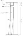
- FIG. 8is a graph showing the relationship between the resonator length and the radius of the ring resonator.
- FIG. 9is a schematic end view along the direction in which the resonator of the modified example of the mode-locked semiconductor laser device of Example 1 extends.
- FIG. 10is a schematic end view along the direction in which the resonator of another modification of the mode-locked semiconductor laser device of Example 1 extends.
- FIG. 11is a schematic view of a ridge stripe structure as viewed from above in still another modified example of the mode-locked semiconductor laser device according to the first embodiment.
- the first light reflecting portion formed on the end face at the first end of the first gain portion and the second light reflecting portion provided on the end face at the third end of the second gain portionconstitute a resonator.
- the resonatorcan be configured to emit laser light.
- the laser device assembly of this indication of such compositionThe first end of the pulse selector and the second end of the first gain section are opposed to each other, The second end of the pulse selector and the semiconductor optical amplifier may be opposed to each other.
- the laser device assembly of such a formis referred to as a “laser device assembly of the first form” for convenience.
- the fourth end portion of the second gain portionmay be configured as a bent waveguide, and thereby, from the fourth end portion of the second gain portion. The generation of return light can be suppressed.
- an optical coupleris arranged between the second end portion of the first gain unit and the pulse selector. Can do.
- the laser device assembly of such a formis called a “laser device assembly of the second form” for convenience.
- the second end of the first gain unit and the optical couplerare optically coupled.
- one end of the optical coupleris opposed to the pulse selector (specifically, the first end of the pulse selector), and the optical coupler
- the other endcan be configured as a bent waveguide.
- the second end portion of the first gain portioncan be formed of a bent waveguide, whereby the second gain portion from the second end portion of the first gain portion can be formed. Generation of return light can be suppressed.
- the fourth end portion of the second gain portionmay be formed of a bent waveguide, whereby return light from the fourth end portion of the second gain portion. Can be suppressed.
- a resonatoris constituted by the light transflective portion formed at the second end portion of the first gain portion and the light reflecting portion provided at the end face at the third end portion of the second gain portion, A laser oscillation can be performed in the resonator.
- the laser device assembly of such a formis called a “laser device assembly of the third form” for convenience.
- the light semi-transmissive portion formed in the first gain portion and the pulse selectorcan be opposed to each other, and in these embodiments, the first gain portion has a first shape.
- the end portionmay be formed of a bent waveguide, and thereby generation of return light from the first end portion of the first gain portion can be suppressed.
- the fourth end portion of the second gain sectionmay be formed of a bent waveguide.
- the first gain sectioncan be made of a mode-locked semiconductor laser element.
- the second gain sectioncan be configured by a mode-locked semiconductor laser element.
- the pulse selectorhas a structure in which a forward bias (forward bias) and a reverse bias are applied,
- a forward biasforward bias
- a reverse biasis applied to the pulse selector, the laser light emitted from the first gain unit can be prevented from entering the semiconductor optical amplifier by the pulse selector.
- the pulse selectorcan be configured to cause the laser light that has passed through the ring resonator to enter the semiconductor optical amplifier.
- the first gain unit, the second gain unit, the ring resonator, the semiconductor optical amplifier, the pulse selector, and the optical devicecan be formed of a stacked structure of compound semiconductor layers having the same structure.
- the compound semiconductor layercan be formed of a nitride-based compound semiconductor, and further, If The first gain unit, the second gain unit, the ring resonator, the semiconductor optical amplifier and the pulse selector, and the optical coupler are provided on the second surface of the substrate, A first electrode is formed on the first surface of the substrate, The first gain section, the second gain section, the ring resonator, the semiconductor optical amplifier and the pulse selector, and at least a part of each top surface of the optical coupler is provided with an independent second electrode. Furthermore, in these cases, the first gain unit, the second gain unit, the ring resonator, the semiconductor optical amplifier and the pulse selector, and the optical coupler have a ridge structure. be able to.
- the first gain unit, the second gain unit, the ring resonator, the semiconductor optical amplifier, and the pulse selectormay be collectively referred to as “semiconductor laser element etc.”.
- semiconductor laser element etc.there is a case where the ring resonator does not need to be provided with the second electrode.
- the second electrodeis provided in the second gain section. May not be provided, and in the laser device assembly of the third embodiment, the second electrode may not be provided in the first gain section.
- the repetition frequency of the laser light pulse in the mode-locked semiconductor laser elementis preferably 1 GHz or less.
- laser device assembly of the present disclosureincluding the preferred configurations and forms described above (hereinafter, these may be collectively referred to as “laser device assembly of the present disclosure” in some cases), ,In particular, (A) a first compound semiconductor layer having a first conductivity type and made of a GaN compound semiconductor, a third compound semiconductor layer (active layer) made of a GaN compound semiconductor, and a second conductivity different from the first conductivity type A stacked structure in which a second compound semiconductor layer having a mold and made of a GaN-based compound semiconductor is sequentially stacked; (B) a second electrode formed on the second compound semiconductor layer, and (C) a first electrode electrically connected to the first compound semiconductor layer; It can be set as the form provided with.
- the first compound semiconductor layeris formed on a substrate or a base.
- the mode-locked semiconductor laser devicemay be a mode-locked semiconductor laser device having a ridge structure, specifically, a ridge stripe type separate confinement heterostructure (SCH structure, separate-confinement heterostructure).
- a mode-locked semiconductor laser element having an oblique ridge stripe type separated confinement heterostructurecan be employed.
- the axis of the mode-locked semiconductor laser element and the axis of the ridge stripe structurecan intersect at a predetermined angle.
- examples of the predetermined angleinclude 0.1 to 10 degrees.
- the axis of the ridge stripe structureis a bisection point at both ends of the ridge stripe structure at one end and two ends of the ridge stripe structure at the other end of the stacked structure opposite to the one end. It is a straight line connecting the equally divided points.
- the axis of the mode-locked semiconductor laser elementrefers to an axis that is orthogonal to one end and the other end.
- the planar shape of the ridge stripe structuremay be linear or curved.
- the width of the ridge stripe structure at the second end (fourth end)is W 2
- the width of the ridge stripe structure at the first end (third end)is W 1 .
- W 1W 2 may be satisfied, or W 2 > W 1 may be satisfied.
- W 2can be in a form of 5 ⁇ m or more, and the upper limit value of W 2 is not limited, but can be exemplified by 4 ⁇ 10 2 ⁇ m, for example. Further, W 1 may be 1.4 ⁇ m to 2.0 ⁇ m.
- Each edge of the ridge stripe structuremay be composed of one line segment, or may be composed of two or more line segments.
- the width of the ridge stripe structureis, for example, configured to be monotonously and gradually widened in a tapered shape from the first end (third end) to the second end (fourth end). be able to.
- the width of the ridge stripe structureis, for example, the same width from the first end (third end) to the second end (fourth end), and then monotonously.
- the width of the ridge stripe structureis first widened from the first end (third end) to the second end (fourth end), for example. After exceeding the maximum width, it can be configured to be narrowed.
- the light reflectivity of this end surfaceis 50% or more. It is preferable.
- a configuration in which a reflective coating layer is formed on this end facecan be adopted.
- the reflective coating layerhas, for example, a laminated structure of at least two types of layers selected from the group consisting of a titanium oxide layer, a tantalum oxide layer, a zirconia oxide layer, a silicon oxide layer, and an aluminum oxide layer. This light reflectance value is much higher than the light reflectance (usually 5% to 10%) of one end face of the laminated structure from which a laser light beam (pulsed laser light) is emitted in a conventional semiconductor laser element. High value.
- the first light reflecting portion formed on the end face at the first end of the first gain portion and the second light reflecting portion or the light reflecting portion provided on the end face at the third end of the second gain portionare: It is preferable to have a high light reflectivity, for example, a reflectivity of 85% or more, preferably a reflectivity of 95% or more.
- the light semi-transmissive part formed at the second end of the first gain partcan be composed of a distributed Bragg reflector layer (Distributed Bragg Reflector layer, DBR layer).
- DBR layerdistributed Bragg Reflector layer
- the refractive index of the second end of the first gain unitmay be periodically modulated (changed) along the transmission direction of the laser light.
- the stacked structurehas a ridge structure composed of at least a part of the second compound semiconductor layer in the thickness direction.
- This ridge structuremay be composed of only the second compound semiconductor layer. It may be composed of a second compound semiconductor layer and a third compound semiconductor layer (active layer), or may be composed of a second compound semiconductor layer, a third compound semiconductor layer (active layer), and a first compound semiconductor layer. It may be composed of a part in the thickness direction.
- the ridge structurecan be formed based on, for example, an etching method.
- the laminated structurecan be specifically composed of an AlGaInN-based compound semiconductor.
- the AlGaInN-based compound semiconductorinclude GaN, AlGaN, GaInN, and AlGaInN.
- these compound semiconductorsmay contain boron (B) atoms, thallium (Tl) atoms, arsenic (As) atoms, phosphorus (P) atoms, and antimony (Sb) atoms as desired.
- the third compound semiconductor layer (active layer) constituting the light emitting region (gain region)desirably has a quantum well structure.
- the third compound semiconductor layer (active layer) having a quantum well structurehas a structure in which at least one well layer and a barrier layer are stacked, but the compound semiconductor constituting the well layer and the compound constituting the barrier layer As a combination of (semiconductor), (In y Ga (1-y) N, GaN), (In y Ga (1-y) N, In z Ga (1-z) N) [where y> z], ( In y Ga (1-y) N, AlGaN) can be exemplified.
- the width of the second electrodeis not less than 0.5 ⁇ m and not more than 50 ⁇ m, preferably not less than 1 ⁇ m and not more than 5 ⁇ m, and the height of the ridge stripe structure is not less than 0.1 ⁇ m, It is 10 ⁇ m or less, preferably 0.2 ⁇ m or more and 1 ⁇ m or less.
- the length direction of the multilayer structureis defined as the X direction
- the width direction of the multilayer structureis defined as the Y direction
- the thickness direction of the multilayer structureis defined as the Z direction.
- a non-doped compound semiconductor layer(for example, a non-doped GaInN layer or a non-doped AlGaN layer) is formed between the third compound semiconductor layer and the electron barrier layer. May be. Furthermore, a non-doped GaInN layer as a light guide layer may be formed between the third compound semiconductor layer and the non-doped compound semiconductor layer.
- the uppermost layer of the second compound semiconductor layermay be structured to be occupied by the Mg-doped GaN layer (p-side contact layer).
- the electron barrier layer, the non-doped compound semiconductor layer, the light guide layer, and the p-side contact layerconstitute a second compound semiconductor layer.
- GaN-based compound semiconductor layers constituting the semiconductor laser device and the likeare sequentially formed on a substrate and a substrate.
- a GaAs substrateis used as the substrate or substrate.
- the GaN substrateis preferred because of its low defect density. ing.
- a method for forming various compound semiconductor layersfor example, GaN-based compound semiconductor layers constituting a semiconductor laser element or the like
- a metal organic chemical vapor deposition methodMOCVD method, MOVPE method
- a molecular beam epitaxy methodMBE
- hydride vapor phase growth methodin which halogen contributes to transport or reaction.
- trimethylgallium (TMG) gas and triethylgallium (TEG) gascan be exemplified as the organic gallium source gas in the MOCVD method, and ammonia gas and hydrazine gas can be exemplified as the nitrogen source gas.
- silicon (Si)may be added as an n-type impurity (n-type dopant), or a GaN-based compound having a p-type conductivity.
- magnesium (Mg)may be added as a p-type impurity (p-type dopant).
- trimethylaluminum (TMA) gasmay be used as the Al source, and trimethylindium (TMI) gas is used as the In source. Use it.
- monosilane gas (SiH 4 gas)may be used as the Si source, and cyclopentadienyl magnesium gas, methylcyclopentadienyl magnesium, or biscyclopentadienyl magnesium (Cp 2 Mg) may be used as the Mg source. .
- n-type impuritiesexamples include Si, Ge, Se, Sn, C, Te, S, O, Pd, and Po, and p-type impurities (p-type dopants) other than Mg.
- Zn, Cd, Be, Ca, Ba, C, Hg, and Srcan be exemplified.
- a mode-locked semiconductor laser element having a saturable absorption regioncan be exemplified. Since the oscillation characteristic can be controlled based on the reverse bias voltage V sa to the saturable absorption region, the oscillation characteristic can be easily controlled.
- a mode-locked semiconductor laser elementis a bi-section type mode-locked semiconductor laser in which a light emitting region and a saturable absorption region are juxtaposed along the length direction (X direction) of a laminated structure.
- Bi-section type mode-locked laser diode device(A) a first compound semiconductor layer having a first conductivity type and made of a GaN compound semiconductor, a third compound semiconductor layer (active layer) constituting a light emitting region and a saturable absorption region made of a GaN compound semiconductor, and A stacked structure in which second compound semiconductor layers having a second conductivity type different from the first conductivity type and made of a GaN-based compound semiconductor are sequentially stacked; (B) a strip-shaped second electrode formed on the second compound semiconductor layer, and (C) a first electrode electrically connected to the first compound semiconductor layer; With The second electrode is separated into a first portion for setting a forward bias state by passing a direct current through the first electrode via the light emitting region and a second portion for applying an electric field to the saturable absorption region.
- the first compound semiconductor layeris formed on a substrate or a base.
- the length of the saturable absorption regioncan be shorter than the length of the light emitting region.
- the length of the second electrode(the total length of the first portion and the second portion) can be shorter than the length of the third compound semiconductor layer (active layer).
- the “length”is a length along the length direction (X direction) of the laminated structure.
- the first part of one second electrode and the second part of two second electrodesare provided, and one end of the first part is sandwiched by one separation groove, Opposite to the second part, the other end of the first part is opposed to the other second part across the other separation groove.
- the first part of the two second electrodes and one first partA second portion of the two electrodes, an end of the second portion sandwiching one separation groove and facing one first portion, and the other end of the second portion sandwiching the other separation groove In the state facing the other first part (that is, the second electrode has a structure in which the second part is sandwiched between the first parts) Can be mentioned.
- a first portion of N second electrodes and a second portion of (N ⁇ 1) second electrodesare provided, and the first portion of the second electrode sandwiches the second portion of the second electrode.
- second portions of the N second electrodes and (N-1) first portions of the second electrodesare provided, and the second portion of the second electrode is the second electrode.
- positioned on both sides of the 1st part of thiscan be mentioned.
- the states of (4) and (5)are: (4 ′) N light emitting regions [carrier injection region, gain region] and (N ⁇ 1) saturable absorption regions [carrier non-injection region] are provided, and the light emitting region sandwiches the saturable absorption region.
- the width of the separation groove for separating the second electrode into the first portion and the second portionis 1 ⁇ m or more, along the length direction (X direction) of the stacked structure in the mode-locked semiconductor laser device. It is desirable that the length is 50% or less, preferably 10 ⁇ m or more and 10% or less. Further, the distance d from the top surface of the portion of the second compound semiconductor layer located outside the both side surfaces of the ridge stripe structure to the third compound semiconductor layer (active layer) is 1.0 ⁇ 10 ⁇ 7 m (0. 1 ⁇ m) or more is preferable. By defining the distance d in this way, saturable absorption regions can be reliably formed on both sides (Y direction) of the third compound semiconductor layer. The upper limit of the distance d may be determined based on an increase in threshold current, temperature characteristics, deterioration in current increase rate during long-term driving, and the like.
- the electrical resistance value between the first part and the second part of the second electrodeis 1 ⁇ 10 times or more, preferably 1 ⁇ 10 2 times or more the electrical resistance value between the second electrode and the first electrode, More preferably, it is 1 ⁇ 10 3 times or more.
- a mode-locked semiconductor laser elementis referred to as a “mode-locked semiconductor laser element having a first configuration” for convenience.
- the electrical resistance value between the first portion and the second portion of the second electrodeis 1 ⁇ 10 2 ⁇ or more, preferably 1 ⁇ 10 3 ⁇ or more, more preferably 1 ⁇ 10 4 ⁇ or more. It is desirable.
- Such a mode-locked semiconductor laser elementis referred to as a “mode-locked semiconductor laser element having a second configuration” for convenience.
- the electric resistance value between the first portion and the second portion of the second electrodeis determined by the second electrode and the first electrode.
- the leakage current flow from the first part to the second part of the second electrodeis surely suppressed by setting the electrical resistance value between the first electrode and the second part to 10 times or more, or 1 ⁇ 10 2 ⁇ or more.
- the reverse bias voltage V sa applied to the saturable absorption region (carrier non-injection region)can be increased, a mode-locking operation having a pulsed laser beam with a shorter pulse time width can be realized.
- such a high electrical resistance value between the first part and the second part of the second electrodecan be achieved simply by separating the second electrode into the first part and the second part by the separation groove. it can.
- the mode-locked semiconductor laser element of the first configuration and the second configurationis not limited,
- the third compound semiconductor layerhas a quantum well structure including a well layer and a barrier layer,
- the thickness of the well layeris 1 nm or more and 10 nm or less, preferably 1 nm or more and 8 nm or less,
- the impurity doping concentration of the barrier layeris 2 ⁇ 10 18 cm ⁇ 3 or more and 1 ⁇ 10 20 cm ⁇ 3 or less, preferably 1 ⁇ 10 19 cm ⁇ 3 or more and 1 ⁇ 10 20 cm ⁇ 3 or less. can do.
- Such a mode-locked semiconductor laser elementmay be referred to as a “mode-locked semiconductor laser element having a third configuration” for convenience.
- the thickness of the well layer constituting the third compound semiconductor layeris defined as 1 nm or more and 10 nm or less, and the impurity doping concentration of the barrier layer constituting the third compound semiconductor layer is 2 ⁇ 10 18 cm. -3 or more and 1 ⁇ 10 20 cm -3 or less, that is, by reducing the thickness of the well layer and increasing the number of carriers in the third compound semiconductor layer, It is possible to obtain a laser light source that can generate a unimodal laser beam that can be reduced, has a short pulse time width, and has few sub-pulse components.
- mode-synchronized drivingcan be achieved with a low reverse bias voltage V sa , and a pulse train of laser light synchronized with external signals (electrical signals and optical signals) can be generated.
- the impurity doped in the barrier layercan be silicon (Si), but is not limited to this, and oxygen (O) can also be used.
- the reverse bias voltage V sais applied between the first electrode and the second part (that is, the first electrode is a positive electrode and the second part is a negative electrode).
- a pulse current or pulse voltage synchronized with the pulse current or pulse voltage applied to the first part of the second electrodemay be applied to the second part of the second electrode, or a DC bias may be applied.
- a currentcan be passed from the second electrode to the first electrode via the light emitting region, and an external electric signal can be superimposed on the first electrode from the second electrode via the light emitting region.
- synchronization between the laser beam and the external electric signalcan be achieved.
- itcan be set as the form which makes an optical signal inject from the end surface of a laminated structure. This also enables synchronization between the laser beam and the optical signal.
- the mode-locked semiconductor laser elementis not limited to the bi-section type (two-electrode type) mode-locked semiconductor laser element, but can be used as a multi-section type (multi-electrode type) mode-locked semiconductor laser element or light emitting region
- a SAL (Saturable Absorber Layer) type in which the saturated absorption region is arranged vertically or a WI (Weakly Index Guide) type mode-locked semiconductor laser device in which a saturable absorption region is provided along the ridge stripe structuremay be adopted. it can.
- the second electrodeis, for example, a palladium (Pd) single layer, a nickel (Ni) single layer, a platinum (Pt) single layer, an indium tin oxide (ITO) single layer, or a palladium layer that is a second compound semiconductor.
- a layered structure of palladium layer / platinum layer in contact with the layer, or a layered structure of palladium layer / nickel layer in which the palladium layer is in contact with the second compound semiconductor layercan be used.
- the thickness of the upper metal layeris desirably 0.1 ⁇ m or more, preferably 0.2 ⁇ m or more.
- the second electrodeis preferably composed of a single layer of palladium (Pd).
- the thicknessis preferably 20 nm or more, and preferably 50 nm or more.
- the second electrodemay be a palladium (Pd) single layer, a nickel (Ni) single layer, a platinum (Pt) single layer, or a lower metal layer and an upper metal layer in which the lower metal layer is in contact with the second compound semiconductor layer.
- the lower metal layeris composed of one type of metal selected from the group consisting of palladium, nickel and platinum, and the upper metal layer has an etching rate when forming the separation groove in the second electrode, Preferably, it is made of a metal that is the same as or similar to the etching rate of the lower metal layer, or higher than the etching rate of the lower metal layer.
- the second waveguideis not provided in the bending waveguide.
- the first electrode electrically connected to the first compound semiconductor layer having the n-type conductivity typeis gold (Au), silver (Ag), palladium (Pd), A single element comprising at least one metal selected from the group consisting of Al (aluminum), Ti (titanium), tungsten (W), Cu (copper), Zn (zinc), tin (Sn), and indium (In). It is desirable to have a layer structure or a multilayer structure, and examples thereof include Ti / Au, Ti / Al, and Ti / Pt / Au.
- the first electrodeis electrically connected to the first compound semiconductor layer.
- the first electrodeis formed on the first compound semiconductor layer, and the first electrode includes a conductive material layer, a conductive substrate, and a base.
- the form connected to the 1st compound semiconductor layer viais included.
- the first electrode and the second electrodecan be formed by, for example, a PVD method such as a vacuum evaporation method or a sputtering method.
- a pad electrodemay be provided on the first electrode or the second electrode for electrical connection with an external electrode or circuit.
- the pad electrodehas a single-layer configuration or a multi-layer configuration including at least one metal selected from the group consisting of Ti (titanium), aluminum (Al), Pt (platinum), Au (gold), and Ni (nickel). It is desirable to have.
- the pad electrodemay have a multilayer configuration exemplified by a multilayer configuration of Ti / Pt / Au and a multilayer configuration of Ti / Au.
- the laser device assembly of the present disclosureincludes a semiconductor optical amplifier (SOA) as described above.
- the semiconductor optical amplifierincludes a laminated structure of a III-V nitride semiconductor layer or a laminated structure of a wide gap semiconductor layer that amplifies the laser light emitted from the first gain section to the outside of the system. It is preferable to do.
- the laser beam emitted from the first gain unitis emitted outside the system via the semiconductor optical amplifier.
- the laminated structurecan be made of an AlGaInN-based compound semiconductor as described above.
- the configuration and structure of the semiconductor optical amplifiercan be substantially the same as the configuration and structure of the mode-locked semiconductor laser element, except that the second electrode is not divided.
- the configuration and structure of the divided mode-locked semiconductor laser elementcan be the same.
- the optical confinement factor of the semiconductor optical amplifieris preferably 3% or less, and preferably 1% or less.
- the first compound semiconductor layerhas a laminated structure of a first cladding layer and a first light guide layer from the substrate side,
- the laminated structurehas a ridge stripe structure composed of a part of the second compound semiconductor layer, the third compound semiconductor layer (active layer), and the first light guide layer in the thickness direction,
- the thickness of the first light guide layeris t 1 and the thickness of the first light guide layer constituting the ridge stripe structure is t 1 ′
- 6 ⁇ 10 ⁇ 7 m ⁇ t 1Preferably, 8 ⁇ 10 ⁇ 7 m ⁇ t 1 Satisfied, 0 (m) ⁇ t 1 ′ ⁇ 0.5 ⁇ t 1
- the semiconductor optical amplifier having such a configurationis referred to as a “first-structure semiconductor optical amplifier”.
- the first-structure semiconductor optical amplifierBy defining the thickness t 1 of the first light guide layer, the light confinement factor can be lowered, and the peak of the light field intensity distribution starts from the third compound semiconductor layer (active layer).
- the optical density in the vicinity of the third compound semiconductor layercan be reduced during high output operation, and optical damage can be prevented. This increases the saturation energy, and can achieve high output.
- the thickness t 1 ′ of the portion of the first light guide layer constituting the ridge stripe structureit is possible to achieve a single mode of the output light beam.
- the slab waveguide widthbeing equal to the thickness of the first light guide layer, a light beam cross-sectional shape close to a perfect circle can be obtained, and the light collection characteristics deteriorate in applications using lenses and optical fibers. This does not cause any negative effects.
- the width of the ridge stripe structurefor example, the width of the ridge stripe structure at the light emitting side end of the semiconductor optical amplifier
- 0.2 ⁇ W ⁇ t 1 ⁇ 1.2 ⁇ WPreferably, 0.2 ⁇ W ⁇ t 1 ⁇ W It is preferable to satisfy this relationship.
- t 1 ⁇ 3 ⁇ 10 ⁇ 6 mIt is desirable to satisfy If crystal growth is performed with the thickness t 1 of the first guide layer being 3 ⁇ 10 ⁇ 6 m or less, the crystal growth surface morphology is not roughened, and the characteristics and electrical characteristics of the laser beam output from the semiconductor optical amplifier are Deterioration can be prevented.
- the semiconductor optical amplifiercan be configured to output a single mode light beam.
- the width dimension of the ridge stripe structure of the optical beam outputted from the end of the light emitting side of the semiconductor optical amplifier and LB Xthe thickness dimension of the ridge stripe structure and LB Y, 0.2 ⁇ LB Y / LB X ⁇ 1.2
- the distance Y CCis t 1 ' ⁇ Y CC ⁇ t 1
- the first optical guide layerhas a high refractive index made of a compound semiconductor material having a refractive index higher than that of the compound semiconductor material constituting the first optical guide layer. It can be set as the structure by which the layer is formed.
- the refractive index of the compound semiconductor material forming the first light guide layeris n G ⁇ 1 , and the high refractive index layer is configured.
- the refractive index of the compound semiconductor materialis n HR
- 0.03 ⁇ n HR ⁇ n G ⁇ 1 ⁇ 0.1Can be obtained.
- the average refractive index of the compound semiconductor material constituting the third compound semiconductor layer (active layer)is n Ac
- n HR ⁇ n AcIs preferably satisfied.
- the second compound semiconductor layerhas a laminated structure of the second light guide layer and the second cladding layer from the substrate side, and the thickness of the first light guide layer is larger than the thickness of the second light guide layer. It can be a thick form.
- the optical confinement coefficientis preferably 3% or less, preferably 1% or less.
- the stacked structurehas a ridge stripe structure composed of at least a portion of the second compound semiconductor layer in the thickness direction,
- the first compound semiconductor layerhas a thickness exceeding 0.6 ⁇ m (as an upper limit of the thickness, for example, 10 ⁇ m can be exemplified),
- a high refractive index layer made of a compound semiconductor material having a refractive index higher than that of the compound semiconductor material constituting the first compound semiconductor layercan be formed in the first compound semiconductor layer.
- the semiconductor optical amplifier having such a configurationis referred to as a “second-structure semiconductor optical amplifier”.
- the semiconductor optical amplifier having the second configurationsince the first compound semiconductor layer has a thickness exceeding 0.6 ⁇ m, the optical confinement factor can be lowered, and the optical field intensity can be reduced. As a result of the distribution peak moving from the third compound semiconductor layer (active layer) to the first compound semiconductor layer, the light density in the vicinity of the third compound semiconductor layer can be reduced during high output operation, thus preventing optical damage.
- the saturation energy of the amplified laser beamis increased, and high output can be achieved.
- a high refractive index layer made of a compound semiconductor material having a refractive index higher than the refractive index of the compound semiconductor material constituting the first compound semiconductor layeris formed in the first compound semiconductor layer. Compared with the case where no rate layer is provided, the single mode condition in the thickness direction of the compound semiconductor layer can be satisfied in a wider range, the cutoff condition can be relaxed, and the single mode light beam can be reduced. Can be output.
- the first compound semiconductor layerhas a laminated structure of a first cladding layer and a first light guide layer from the substrate side,
- the first light guide layerhas a thickness exceeding 0.6 ⁇ m
- the high refractive index layercan be formed in the first light guide layer. That is, in such a form, the first light guide layer is formed by laminating the first portion of the first light guide layer, the high refractive index layer, and the second portion of the first light guide layer from the substrate side. It has the structure made.
- first portion of the first light guide layeris referred to as “first-A light guide layer”
- the second portion of the first light guide layeris referred to as “first-B light guide” for convenience. Called “layer”.
- the thickness of the first 1-B light guide layeris 0.25 ⁇ m.
- An example of the upper limit of the value obtained by subtracting the thickness of the high refractive index layer from the thickness of the first light guide layeris 5 ⁇ m.
- the refractive index of the compound semiconductor material constituting the first light guide layeris n G-1 and the refractive index of the compound semiconductor material constituting the high refractive index layer is n HR , 0 ⁇ n HR -n G-1 ⁇ 0.3
- 0.02 ⁇ n HR ⁇ n G ⁇ 1 ⁇ 0.2Can be obtained.
- the average refractive index of the compound semiconductor material constituting the third compound semiconductor layer (active layer)is n Ac , n HR ⁇ n Ac Is preferably satisfied.
- the semiconductor optical amplifiercan output a single mode light beam.
- the width dimension of the ridge stripe structure of the optical beam outputted from the end of the light emitting side of the semiconductor optical amplifier and LB Xthe thickness dimension of the ridge stripe structure and LB Y, 3 ⁇ 10 0 ⁇ LB Y / LB X ⁇ 1 ⁇ 10 3
- the distance Y CCis 0m ⁇ Y CC ⁇ (Thickness of first light guide layer)
- the laser apparatus assembly of the present disclosureis, for example, an optical disc system, a communication field, an optical information field, an optoelectronic integrated circuit, a field applying a nonlinear optical phenomenon, an optical switch, a laser measurement field, various analysis fields, an ultrafast spectroscopy field, Multi-photon excitation spectroscopy field, mass spectrometry field, field of microspectroscopy using multi-photon absorption, quantum control of chemical reaction, nano 3D processing field, various processing fields applying multi-photon absorption, medical field, bio-imaging field It can be applied to fields such as the quantum information communication field and the quantum information processing field.
- Example 1relates to the laser device assembly of the present disclosure, and specifically relates to the laser device assembly of the first embodiment.
- a schematic plan view of the monolithic laser device assembly of Example 1is shown in FIGS. 1A and 1B.
- FIG. 5shows a schematic cross-sectional view along the direction perpendicular to the direction in which the resonator of the mode-locked semiconductor laser element constituting the laser device assembly of Example 1 extends.
- a typical end viewis shown in FIG. 6, and the operation timing of the pulse selector is schematically shown in FIGS. 7A and 7B.
- FIG. 1Ais a diagram clearly showing elements constituting the monolithic laser device assembly 10A of the first embodiment
- FIG. 1Boverlooks the entire monolithic laser device assembly 10B of the first embodiment. It is a figure.
- the effective resonator length l reff of the ring resonatoris such that the circumference of the ring resonator is I r , and the ring resonator and the mode-locked semiconductor laser are used.
- the branching ratio with the elementis ⁇
- l reff⁇ (1- ⁇ 2 ) / ⁇ 2 ⁇ I r
- ⁇0.1
- the branching ratio ⁇can be set to a desired value based on the coupled mode theory.
- the refractive index of the entire ring resonatorcan be changed.
- the resonator length of the ring resonatorcan be set to a desired length.
- the refractive index of the entire ring resonatorcan be controlled by using a transparent conductive material such as ITO as the material constituting the second electrode formed on the top surface of the ring resonator.
- the monolithic laser device assembly 10A of Example 1is A first gain unit 20 having a first end 20A and a second end 20B; A second gain unit 30 having a third end 30A and a fourth end 30B; One or multiple (one in the first embodiment) ring resonator 40; A semiconductor optical amplifier 50 for amplifying the laser light emitted from the first gain unit 20, and A pulse selector 60 disposed between the first gain unit 20 and the semiconductor optical amplifier 50; With The ring resonator 40 is optically coupled to the first gain unit 20 and optically coupled to the second gain unit 30. Laser oscillation is performed in one of the first gain unit 20 and the second gain unit 30.
- the 1st light reflection part(specifically 1st light reflection surface) formed in the end surface 20a in the 1st end part 20A of the 1st gain part 20 is shown.
- 23 and the second light reflecting part (specifically, the second light reflecting surface) 33 provided on the end face 30a of the third end part 30A of the second gain part 30constitutes a resonator.
- the 1st light reflection part 23 and the 2nd light reflection part 33are comprised from the light reflection surface which consists of a highly reflective coating layer (HR). Further, laser oscillation is performed in this resonator.
- HRhighly reflective coating layer
- the first end 60A of the pulse selector 60 and the second end 20B of the first gain unit 20are opposed to each other, and the second end 60B of the pulse selector 60 and the semiconductor optical amplifier 50 are opposed to each other.
- the fourth end 30B of the second gain unit 30is formed of a bent waveguide 36, and the generation of return light from the fourth end 30B of the second gain unit 30 is suppressed.
- the laminated structure 90is left between the first end 60 ⁇ / b> A of the pulse selector 60 and the second end 20 ⁇ / b> B of the first gain unit 20.
- the laminated structure 90is also left between the second end 60B of the pulse selector 60 and the semiconductor optical amplifier 50.
- Reference numeral 91indicates a region of the laminated structure other than the ridge structure, and this region is composed of at least a part in the thickness direction of the second compound semiconductor layer. That is, this region may be composed of a part of the first compound semiconductor layer in the thickness direction, may be composed of the third compound semiconductor layer (active layer) and the first compound semiconductor layer, You may be comprised from the part of the thickness direction of the 2nd compound semiconductor layer, the 3rd compound semiconductor layer (active layer), and the 1st compound semiconductor layer.
- the ridge structure and the layered structure region 91 other than the ridge structurecan be formed based on, for example, an etching method.
- the first gain unit 20when the stacked structure 90 between the first gain unit 20 and the pulse selector 60 is removed, the first gain unit 20 facing the pulse selector 60 is used.
- a non-reflective coating layer (AR)is formed on the end face (light emission end face) of the second end portion 20B.
- the first gain unit 20includes a mode-locked semiconductor laser element 20 '.
- FIG. 6shows a schematic end view along the direction in which the resonator of the mode-locked semiconductor laser element 20 ′ extends (that is, along the arrow II in FIG. 5).
- FIG. 5shows a schematic cross-sectional view along the direction perpendicular to the direction in which the vessel extends (that is, along the arrow II-II in FIG. 6).
- the mode-locked semiconductor laser element 20 ′has a light emitting region (gain region) 21 and a saturable absorption region 22.
- the saturable absorption region 22is provided on the first end face 20 a side in the first gain unit 20.
- the mode-locked semiconductor laser element 20 ′is composed of a bi-section type mode-locked semiconductor laser element in which a light emitting region 21 and a saturable absorption region 22 are juxtaposed in the cavity direction.
- the mode-locked semiconductor laser element 20 ′A first compound semiconductor layer 230 made of a GaN-based compound semiconductor and having a first conductivity type (in the embodiment, an n-type conductivity type); A third compound semiconductor layer (active layer) 240 made of a GaN-based compound semiconductor, and A second compound semiconductor layer 250 made of a GaN-based compound semiconductor and having a second conductivity type (p-type conductivity type in the embodiment) different from the first conductivity type; However, it has the laminated structure formed by laminating sequentially.
- the first compound semiconductor layer 230is formed on a base (specifically, the substrate 221).
- a bi-section type mode-locked semiconductor laser device 20 ′ having an emission wavelength of 405 nm bandas shown in FIGS.
- the mode-locked semiconductor laser device 20 ′has a ridge stripe type separated confinement heterostructure (SCH structure).
- SCH structure
- the mode-locked semiconductor laser device 20 ′has a peak power light density of 1 ⁇ 10 10 watts / cm 2 or more, preferably 1.4 ⁇ 10 10. It is a current-injection type mode-locked semiconductor laser device that has a watt / cm 2 or more and a carrier density of 1 ⁇ 10 19 / cm 3 or more and is passive mode-locked, active mode-locked, or hybrid mode-locked.
- the mode-locked semiconductor laser elementis made a current injection type, so that it can be compared with a light-pumped mode-locked semiconductor laser element. And has the advantage of high energy efficiency.
- the second electrode 262applies an electric field to the first portion 262A for making a forward bias state by passing a direct current through the first electrode 261 via the light emitting region (gain region) 21 and the saturable absorption region 22.
- the second groove 262Cis separated from the second portion 262B (second portion 262B for applying the reverse bias voltage V sa to the saturable absorption region 22) by the separation groove 262C.
- the electrical resistance value(sometimes referred to as “separation resistance value”) between the first portion 262A and the second portion 262B of the second electrode 262 is between the second electrode 262 and the first electrode 261.
- the electrical resistance valueis 1 ⁇ 10 times or more, specifically 1.5 ⁇ 10 3 times.
- the electrical resistance value (separation resistance value) between the first portion 262A and the second portion 262B of the second electrode 262is 1 ⁇ 10 2 ⁇ or more, specifically, 1.5 ⁇ 10 4 ⁇ . is there.
- the total length of the mode-locked semiconductor laser device 20 ′is 1.00 mm, and the lengths of the first portion 262A, the second portion 262B, and the separation groove 262C of the second electrode 262 are 0.96 mm, 0.03 ⁇ m, and 0.01 ⁇ m, respectively. It was. Further, the width of the ridge stripe structure 255 was set to 1.4 ⁇ m.
- the first gain unit 20, the second gain unit 30, the ring resonator 40, the semiconductor optical amplifier 50, and the pulse selector 60are composed of a stacked structure of compound semiconductor layers having the same structure.
- the semiconductor layeris made of a nitride compound semiconductor.
- the first gain unit 20, the second gain unit 30, the ring resonator 40, the semiconductor optical amplifier 50, and the pulse selector 60are provided on the second surface 221B of the substrate 221, A first electrode 261 is formed on the first surface 221A of the substrate 221.
- An independent second electrodeis provided on at least a part of the top surfaces of the first gain unit 20, the second gain unit 30, the ring resonator 40, the semiconductor optical amplifier 50, and the pulse selector 60.
- the first gain unit 20, the second gain unit 30, the ring resonator 40, the semiconductor optical amplifier 50, and the pulse selector 60have a ridge structure.
- the mode-locked semiconductor laser device 20 ′is specifically a mode-locked semiconductor laser device having a ridge stripe type separated confinement heterostructure (SCH structure). More specifically, this index guide type GaN-based semiconductor laser element made of AlGaInN has a ridge stripe structure.
- the first compound semiconductor layer 230, the third compound semiconductor layer (active layer) 240, and the second compound semiconductor layer 250are specifically made of an AlGaInN-based compound semiconductor. More specifically, It has the layer structure shown in Table 1.
- Table 1the compound semiconductor layer described below is a layer closer to the n-type GaN substrate 221.
- the band gap of the compound semiconductor constituting the well layer in the third compound semiconductor layer 240is 3.06 eV.
- the mode-locked semiconductor laser element 20 ′ in Example 1 or Examples 2 to 3 described lateris provided on the (0001) plane of the n-type GaN substrate 221, and the third compound semiconductor layer 240 has a quantum well structure.
- Have The (0001) plane of the n-type GaN substrate 221is also called a “C plane” and is a crystal plane having polarity.
- Second compound semiconductor layer 250p-type GaN contact layer (Mg doped) 254 p-type GaN (Mg-doped) / AlGaN superlattice cladding layer 253 p-type AlGaN electron barrier layer (Mg doped) 252 Non-doped GaInN optical guide layer 251
- the p-type GaN contact layer 254 and the p-type GaN / AlGaN superlattice cladding layer 253are partially removed by the RIE method to form a ridge stripe structure 255.
- a laminated insulating film 256 made of SiO 2 / Siis formed on both sides of the ridge stripe structure 255.
- the SiO 2 layeris the lower layer and the Si layer is the upper layer.
- the difference between the effective refractive index of the ridge stripe structure 255 and the effective refractive index of the laminated insulating film 256is 5 ⁇ 10 ⁇ 3 to 1 ⁇ 10 ⁇ 2 , specifically 7 ⁇ 10 ⁇ 3 .
- a second electrode (p-side ohmic electrode) 262is formed on the p-type GaN contact layer 254 corresponding to the top surface of the ridge stripe structure 255.
- a first electrode (n-side ohmic electrode) 261 made of Ti / Pt / Auis formed on the back surface of the n-type GaN substrate 221.
- the compound semiconductor layer doped with Mg in the light density distribution generated from the third compound semiconductor layer 240 and its vicinityis used.
- the p-type AlGaN electron barrier layer 252the p-type GaN / AlGaN superlattice cladding layer 253, and the p-type GaN contact layer 254 from overlapping as much as possible, internal loss can be reduced within a range where the internal quantum efficiency does not decrease. Suppressed. As a result, the threshold current density at which laser oscillation is started is reduced.
- the distance d from the third compound semiconductor layer 240 to the p-type AlGaN electron barrier layer 252is 0.10 ⁇ m
- the height of the ridge stripe structure 255is 0.30 ⁇ m
- the second electrode 262 and the third compound semiconductor layeris 0.40 ⁇ m. did.
- the first gain unit 20the second gain unit 30, the ring resonator 40, the semiconductor optical amplifier 50, and the pulse selector.
- the second electrode formed on the top surface of 60is hatched for clarity.
- Pad portions 24 and 25 for connecting the second electrode 262 to the outsideare provided on the second electrode 262 in the first gain portion 20. That is, the pad portion 24 is provided for the light emitting region (gain region) 21, and the pad portion 25 is provided for the saturable absorption region 22.
- the second electrode in the ring resonator 40is provided with a pad portion 41 for connecting the second electrode to the outside, and the second electrode in the second gain portion 30 is provided with the second electrode.
- a pad portion 34 for connecting to the outsideis provided, and a pad portion 61 for connecting the second electrode to the outside is provided on the second electrode in the pulse selector 60.
- the substrate 221is provided with a first electrode (n-side ohmic electrode) 261 common to the first gain unit 20, the second gain unit 30, the ring resonator 40, the semiconductor optical amplifier 50, and the pulse selector 60.
- a part of the laser light (determined by ⁇ ) generated in the first gain unit 20is optically coupled to the ring resonator 40 and moves to the ring resonator 40.
- a part of the laser light in the ring resonator 40(determined by ⁇ ) is optically coupled to the second gain unit 30 and moves to the second gain unit 30.
- the portion of the laser light that is not coupled to the ring resonator 40proceeds to the bending waveguide 36, but the second electrode is not formed in this portion, so gain is obtained. Absent.
- the laser light in the second gain unit 30is optically coupled to the ring resonator 40 and moves to the ring resonator 40. Then, after a certain residence time in the ring resonator 40, a part of the laser light (determined by ⁇ ) in the ring resonator 40 is optically coupled to the first gain unit 20 and moves to the first gain unit 20. . In this way, laser light is generated in the resonator constituted by the first light reflecting portion 23 and the second light reflecting portion 33. A part of the laser light in the first gain unit 20 is incident on the semiconductor optical amplifier 50 via the pulse selector 60, is optically amplified in the semiconductor optical amplifier 50, and is emitted from the semiconductor optical amplifier 50.
- the ring length of the ring resonator 40is oscillated so as to oscillate on the short wave side of the amplified spontaneous emission (ASE) peak of the semiconductor optical amplifier 50. And adjusting the refractive index of the laminated structure.
- the ring resonator 40may be provided with a second electrode and gain may be obtained by the amount of current, or may be operated with a transparent current to function as a passive waveguide.
- “operating with a transparent current”means a state in which no gain is obtained in the ring resonator 40 by providing the second electrode in the ring resonator 40 and adjusting the amount of current flowing in the ring resonator 40. This means that the ring resonator 40 is operated.
- the pulse selector 60can be driven independently of the mode-locked semiconductor laser element 20 ′.
- the pulse selector 60has a structure to which a positive bias (forward bias) and a reverse bias are applied (that is, has a first electrode and a second electrode),
- a positive biasforward bias
- a reverse biasis applied to the pulse selector 60
- the pulse selector 60is in a closed state, and the laser light emitted from the first gain unit 20 is incident on the semiconductor optical amplifier 50 by the pulse selector 60.
- the pulse selector 60causes the laser light that has passed through the ring resonator 40 to enter the semiconductor optical amplifier 50.
- the timing at which the pulse selector 60 is opened / closedis optimized by monitoring the current flowing through the saturable absorption region 22 of the mode-locked semiconductor laser device 20 ′ when driven in passive mode synchronization. be able to.
- the pulse selector 60also has a function of filtering the amplified spontaneous emission light from the semiconductor optical amplifier 50 and the amplified spontaneous emission light from the mode-locked semiconductor laser element 20 ′. It is possible to suppress the return light to 'and the amplified spontaneous emission light of the mode-locked semiconductor laser device 20 ′ from being amplified by the semiconductor optical amplifier 50.
- the pulse selector 60by driving the pulse selector 60 as shown in FIG. 7A, noise light can be suppressed.
- the laser light pulsescan be thinned as shown in FIG. 7B.
- the repetition frequency of the laser light pulsescan be set to the fundamental frequency. Can be made lower.
- the repetition frequency of a laser beam pulseis 1 GHz or less.
- the repetition frequency of the laser light pulsecan be optimized according to the semiconductor optical amplifier.
- the pulse selectoris provided, pulse light having a desired wavelength can be incident on the semiconductor optical amplifier.
- a laser light pulse light source having a high peak powercan be reduced in size, and a monolithic laser device assembly that achieves both high output and downsizing can be provided.
- Example 2is a modification of Example 1, but relates to the laser device assembly of the second mode.
- 2A and 2Bare schematic plan views of the monolithic laser device assembly 10B according to the second embodiment.
- FIG. 2Ais a diagram clearly showing elements constituting the monolithic laser device assembly 10B of the second embodiment, and FIG. 2B overlooks the entire monolithic laser device assembly 10B of the second embodiment. It is a figure.
- the optical coupler 70is disposed between the second end 20B of the first gain unit 20 and the pulse selector 60.
- the second end 20B of the first gain unit 20 and the optical coupler 70are optically coupled.
- One end portion of the optical coupler 70is opposed to the pulse selector 60 (specifically, the first end portion 60A of the pulse selector 60), and the other end portion of the optical coupler 70 is constituted by a bent waveguide 76.
- the tip of the second end 20B of the first gain unit 20is formed of a bent waveguide 26, thereby suppressing the generation of return light from the second end 20B of the first gain unit 20. Can do.
- the fourth end 30 ⁇ / b> B of the second gain unit 30is configured by a bending waveguide 36.
- the laminated structure 90is left between one end of the optical coupler 70 and the pulse selector 60 (specifically, the first end 60A of the pulse selector 60).
- the laminated structure 90is also left between the second end 60B of the pulse selector 60 and the semiconductor optical amplifier 50.
- the optical coupler 70is composed of a laminated structure of compound semiconductor layers having the same structure as the laminated structure constituting the mode-locking semiconductor laser element 20 '.
- the optical coupler 70is provided on the second surface 221 ⁇ / b> B of the substrate 221.
- An independent second electrodeis provided on the top surface of the optical coupler 70, and a pad portion 71 for connecting the second electrode to the outside is provided.
- Example 3is a modification of Example 1, but relates to the laser device assembly of the third mode.
- 3 and 4are schematic plan views of the monolithic laser device assembly 10C according to the third embodiment.
- FIG. 3is a diagram clearly showing elements constituting the monolithic laser device assembly 10C of the third embodiment, and FIG. 4 overlooks the entire monolithic laser device assembly 10C of the third embodiment. It is a figure.
- the light semi-transmissive portion 128 formed at the second end portion 120B of the first gain portion 120 and the end face of the third end portion 130A of the second gain portion 130are provided.
- the provided light reflecting portion 133constitutes a resonator, and laser oscillation is performed in this resonator.
- the light semi-transmissive portion 128 formed in the first gain portion 120 and the pulse selector 60(specifically, the first end portion 60A of the pulse selector 60) face each other.
- the first end portion 120A of the first gain unit 120is formed of a bent waveguide 127, and thereby, generation of return light from the first end portion 120A of the first gain unit 120 can be suppressed,
- the resonance mode that circulates in the opposite direction(counterclockwise in the example shown in FIG. 3) can be suppressed.
- the first gain unit 120has the same configuration and structure as the second gain unit 30 described in the first embodiment. However, the difference is that instead of having the second light reflecting portion (specifically, the second light reflecting surface) 33, a light semi-transmissive portion 128 is provided.
- the fourth end portion 130 ⁇ / b> B of the second gain unit 130is configured by a bending waveguide 136.
- the light semi-transmissive portion 128is composed of a distributed Bragg reflector layer.
- the mode-locked semiconductor laser device 130 ′ constituting the second gain section 130has substantially the same configuration and structure as the mode-locked semiconductor laser device 20 ′ described in the first embodiment. That is, the second gain unit 130 is (A) a first compound semiconductor layer 230 having a first conductivity type (specifically, an n-type conductivity type) made of a GaN-based compound semiconductor, a light-emitting region (gain region) 131 made of a GaN-based compound semiconductor, and a possible A third compound semiconductor layer (active layer) 240 constituting the saturated absorption region 132 and a second conductivity type (specifically, a p-type conductivity type) different from the first conductivity type, and from a GaN-based compound semiconductor A stacked structure in which the second compound semiconductor layers 250 are sequentially stacked; (B) a strip-shaped second electrode 262 formed on the second compound semiconductor layer 250, and (C) a first electrode 261 electrical
- the second gain section 130 including the mode-locked semiconductor laser element 130 ′has a ridge stripe type separated confinement heterostructure (SCH structure).
- the second electrode 262 in the second gain section 130is provided with pad sections 134 and 135 for connecting the second electrode 262 to the outside.
- the pad portion 134is provided for the light emitting region (gain region) 131
- the pad portion 135is provided for the saturable absorption region 132.
- two ring resonators 40 and 42are provided.
- the second electrode in the ring resonator 42is provided with a pad portion 43 for connecting the second electrode to the outside.
- a third gain unit 180optically coupled to the ring resonators 40 and 42 is disposed. Bending waveguides 186 and 187 are arranged at one end and the other end of the third gain section 180.
- An independent second electrodeis provided on the top surface of the third gain portion 180, and a pad portion 184 for connecting the second electrode to the outside is provided.
- the number of ring resonatorsis not limited to two. Also in the first or second embodiment, a plurality of ring resonators 40 and 42 and the third gain unit 180 can be provided.
- the laminated structure 90is left between the light semi-transmissive portion 128 and the pulse selector 60 (specifically, the first end portion 60A of the pulse selector 60).
- the laminated structure 90is also left between the second end 60B of the pulse selector 60 and the semiconductor optical amplifier 50.
- the present disclosurehas been described based on the preferred embodiments, the present disclosure is not limited to these embodiments.
- the configurations of the laser device assembly, the mode-locked semiconductor laser element, and the semiconductor optical amplifier, and the configuration of the structures described in the embodimentsare examples, and can be changed as appropriate. In the embodiments, various values are shown, but these are also exemplifications. For example, if the specifications of the mode-locked semiconductor laser element and the semiconductor optical amplifier to be used are changed, it is natural that they change.
- the axis of the mode-locked semiconductor laser element or semiconductor optical amplifier and the axis of the ridge stripe structuremay intersect at a predetermined angle, or the planar shape of the ridge stripe structure may be tapered.
- Mode-locked semiconductor laser devicemulti-section type (multi-electrode type) mode-locked semiconductor laser device
- first portion 262A of one second electrode and second portions 262B 1 and 262B 2 of two second electrodesIs a schematic end view of FIG. 9 and FIG.
- one end of the first portion 262Ais opposed to one second portion 262B 1 across one separation groove 262C 1 and the other end of the first portion 262A.
- FIG. 10shows a schematic end view of a mode-locked semiconductor laser device in which the first portions 262A 1 and 262A 2 of two second electrodes and the second portion 262B of one second electrode are provided.
- the end of the second portion 262Bis opposed to one first portion 262A 1 across one separation groove 262C 1
- the other end of the second portion 262Bis It faces the other first portion 262A 2 across the other separation groove 262C 2 .
- One saturable absorption region 22, 132is sandwiched between two light emitting regions 21 1 , 131 1 , 21 2 , 131 2 .
- the mode-locked semiconductor laser elementmay be a mode-locked semiconductor laser element having an oblique ridge stripe type separated confinement heterostructure having an oblique waveguide.
- FIG. 11shows a schematic view of the ridge stripe structure in such a mode-locked semiconductor laser device as viewed from above.
- This mode-locked semiconductor laser devicehas a structure in which two linear ridge stripe structures are combined, and the value of the angle ⁇ at which the two ridge stripe structures intersect is, for example, 0 ⁇ ⁇ 10 (degrees) Preferably, 0 ⁇ ⁇ 6 (degrees) Is desirable.
- the mode-locked semiconductor laser element and the semiconductor optical amplifierare provided on the C-plane and ⁇ 0001 ⁇ plane which are the polar planes of the n-type GaN substrate, but instead are the ⁇ 11-20 ⁇ plane.
- a surface, M surfacewhich is ⁇ 1-100 ⁇ surface, nonpolar surface such as ⁇ 1-102 ⁇ surface, or ⁇ 11-2n ⁇ surface including ⁇ 11-24 ⁇ surface and ⁇ 11-22 ⁇ surface , ⁇ 10-11 ⁇ plane, ⁇ 10-12 ⁇ plane may be provided with a mode-locked semiconductor laser element or a semiconductor optical amplifier.
- the ⁇ 11-2n ⁇ planemeans a nonpolar plane that forms approximately 40 degrees with respect to the C plane.
- this indicationcan also take the following structures.
- a first gain sectionhaving a first end and a second end; A second gain section having a third end and a fourth end;
- One or multiple ring resonatorsA semiconductor optical amplifier that amplifies the laser light emitted from the first gain section; and
- a pulse selectordisposed between the first gain section and the semiconductor optical amplifier;
- the ring resonatoris optically coupled to the first gain section and optically coupled to the second gain section, A monolithic laser device assembly in which laser oscillation is performed in any one of a first gain section and a second gain section.
- a resonatoris constituted by the light transflective portion formed at the second end portion of the first gain portion and the light reflecting portion provided at the end face at the third end portion of the second gain portion, The laser device assembly according to [A01], wherein laser oscillation is performed in the resonator.
- the laser device assembly according to [A10]The laser device assembly according to [A09], wherein the light semi-transmissive portion formed in the first gain portion and the pulse selector face each other.
- A11]The laser device assembly according to [A09] or [A10], in which the first end of the first gain section is formed of a bent waveguide.
- [A12]The laser device assembly according to any one of [A09] to [A11], wherein the fourth end of the second gain section is formed of a bent waveguide.
- [A13]The laser device assembly according to any one of [A02] to [A08], in which the first gain section includes a mode-locked semiconductor laser element.
- [A14]The laser device assembly according to any one of [A09] to [A12], in which the second gain section includes a mode-locked semiconductor laser element.
- the pulse selectorhas a structure to which a forward bias and a reverse bias are applied, When a positive bias is applied to the pulse selector, the laser light emitted from the first gain unit enters the semiconductor optical amplifier, When a reverse bias is applied to the pulse selector, laser light emitted from the first gain section is blocked from entering the semiconductor optical amplifier by the pulse selector [A01] to [A14]
- the first gain section, the second gain section, the ring resonator, the semiconductor optical amplifier, and the pulse selectorare any one of [A01] to [A16], which includes a stacked structure of compound semiconductor layers having the same structure.
- the first gain unit, the second gain unit, the ring resonator, the semiconductor optical amplifier, and the pulse selectorare provided on the second surface of the substrate, A first electrode is formed on the first surface of the substrate, In [A17] or [A18], an independent second electrode is provided on at least a part of the top surface of each of the first gain section, the second gain section, the ring resonator, the semiconductor optical amplifier, and the pulse selector.
- the laser device assemblyas described.
- [A20]The laser device assembly according to any one of [A01] to [A19], wherein the first gain unit, the second gain unit, the ring resonator, the semiconductor optical amplifier, and the pulse selector have a ridge structure.
- 10A, 10B, 10CMonolithic laser device assembly, 20, 120... First gain section, 20 ', 130'... Mode-locked semiconductor laser element, 20A, 120A.
- First end portion of the first portion, 20B, 120BSecond end portion of the first gain portion, 20a ... End face of the first end portion of the first gain portion, 21, 131 ... Light emitting region (gain region) ), 22, 132, saturable absorption region, 23, 133, first light reflecting portion (first light reflecting surface), 24, 25, 34, 35, 41, 43, 61, 71, 84, 134, 135 ... pad part, 26, 27, 36, 76, 86, 87, 127, 136 ... bending waveguide, 128 ...
- 221AFirst surface of substrate
- 221BSecond surface of substrate
- 230First compound semiconductor layer
- 231n-type AlGaN cladding layer
- 232n-type GaN cladding layer
- 240Third compound semiconductor layer (active layer), 250... Second compound semiconductor layer, 251.
- 225P-type AlGaN electron barrier layer (Mg doped)
- 253P-type GaN (Mg doped) / AlGaN superlattice cladding layer
- 255... ridge stripe structure
- 261... first electrode, 262 ... second electrode, 262A ... first portion of the second electrode, 262B ... second of the second electrode.
- Part, 262Cseparation groove
Landscapes
- Physics & Mathematics (AREA)
- General Physics & Mathematics (AREA)
- Optics & Photonics (AREA)
- Condensed Matter Physics & Semiconductors (AREA)
- Electromagnetism (AREA)
- Nonlinear Science (AREA)
- Geometry (AREA)
- Engineering & Computer Science (AREA)
- Microelectronics & Electronic Packaging (AREA)
- Semiconductor Lasers (AREA)
Abstract
Description
Translated fromJapanese本開示は、レーザ装置組立体に関する。The present disclosure relates to a laser device assembly.
超短パルスレーザに関する技術は、1960年後半から進展し始め、近年、急速に発展し、盛んに研究が行われている。ところで、その光源として、主に、チタンサファイアレーザを代表とする高価で大型、且つ、高精度の固体レーザ装置が用いられており、この点が技術の普及を阻害する要因の1つとなっている。もしも超短パルスレーザが半導体レーザ素子で実現できれば、大幅な小型化、低価格化、高安定性化がもたらされ、この分野の高度な科学技術を普及させる上でブレイクスルーになることが期待できる。例えば、波長領域が405nm帯である超短パルスレーザが半導体レーザ素子のみで実現できれば、ブルーレイ(登録商標)の次の体積型次世代光ディスク光源として用いることができるだけでなく、可視光域の全波長帯をカバーした手軽な超短パルス光源が実現できる。それ故、医療、バイオイメージング、光造形等の領域だけでなく、種々の幅広い分野で要求される光源を提供することができ、科学技術の進歩に著しい貢献をもたらすと考えられる。Technology related to ultra-short pulse lasers has started to progress from the latter half of 1960, and has developed rapidly and has been actively studied in recent years. By the way, as the light source, an expensive, large-sized, and high-precision solid-state laser device typified by a titanium sapphire laser is mainly used, and this is one of the factors hindering the spread of the technology. . If an ultra-short pulse laser can be realized with a semiconductor laser element, it will bring about a significant reduction in size, cost and stability, and is expected to be a breakthrough in disseminating advanced science and technology in this field. it can. For example, if an ultrashort pulse laser having a wavelength region of 405 nm band can be realized only by a semiconductor laser element, it can be used as a next-generation volume type next-generation optical disk light source of Blu-ray (registered trademark), and all wavelengths in the visible light region. A simple ultra-short pulse light source covering the band can be realized. Therefore, it is possible to provide light sources required not only in medical, bioimaging and stereolithography, but also in a wide variety of fields, which is considered to make a significant contribution to the advancement of science and technology.
ところで、種々の幅広い分野での使用の拡大には更なる小型化が望まれるが、そのためには、超短パルスレーザを半導体レーザ素子から構成し、半導体レーザ素子から出射されるレーザ光を半導体光増幅器(Semiconductor Optical Amplifier,SOA)で増幅し、しかも、半導体レーザ素子と半導体光増幅器とを同一基板に集積化する、モノリシック型のレーザ装置組立体の開発が強く望まれている。By the way, in order to expand the use in various wide fields, further miniaturization is desired. For that purpose, an ultrashort pulse laser is composed of a semiconductor laser element, and laser light emitted from the semiconductor laser element is converted into a semiconductor light. Development of a monolithic laser device assembly that amplifies with an amplifier (Semiconductor Optical Amplifier, SOA) and integrates a semiconductor laser element and a semiconductor optical amplifier on the same substrate is strongly desired.
モノリシック型ではない従来のレーザ装置組立体が、例えば、特開2012-015266公報から周知である。このレーザ装置組立体は、レーザ光源100及び半導体光増幅器200から構成されている。A conventional laser device assembly which is not a monolithic type is known from, for example, Japanese Patent Application Laid-Open No. 2012-015266. This laser device assembly includes a
ところで、これまでに開発されてきた半導体レーザ素子は、レーザ光パルスの繰返し周波数をギガヘルツ帯とする設計がなされている。その理由は、半導体光増幅器におけるキャリア寿命がナノ秒オーダーであることから、半導体光増幅器による効果的な増幅を得るためである。半導体レーザ素子におけるレーザ光パルスの繰返し周波数は共振器長で決まるため、共振器長を15cmとすると1ギガヘルツの繰返し周波数を得ることができる。ところで、外部共振器を有していない半導体レーザ素子を想定した場合、共振器長はチップサイズで律速される結果、レーザ光パルスの繰返し周波数は数十ギガヘルツ乃至100ギガヘルツとなってしまう。その結果、半導体光増幅器による効率的な増幅が困難になる。By the way, the semiconductor laser elements that have been developed so far have been designed to have a repetition frequency of laser light pulses of a gigahertz band. The reason is to obtain effective amplification by the semiconductor optical amplifier because the carrier lifetime in the semiconductor optical amplifier is on the order of nanoseconds. Since the repetition frequency of the laser light pulse in the semiconductor laser element is determined by the resonator length, a repetition frequency of 1 gigahertz can be obtained when the resonator length is 15 cm. By the way, when a semiconductor laser element having no external resonator is assumed, the resonator length is rate-determined by the chip size, and as a result, the repetition frequency of the laser light pulse becomes several tens of gigahertz to 100 gigahertz. As a result, efficient amplification by the semiconductor optical amplifier becomes difficult.
一方、共振器長を長くする手法として、リング共振器が提案されている。リング共振器への光結合の割合(分岐比κ)を低くすることで、実効的な共振器長を物理的なチップサイズ以上にすることが可能である。これまでに、リング共振器長の異なる複数のリング共振器を用いることで、その透過特性の波長依存性を利用して、可変波長光源として様々な提案がされている(例えば、WO2007/029647号公報参照)。On the other hand, a ring resonator has been proposed as a method for increasing the resonator length. By reducing the ratio of optical coupling to the ring resonator (branching ratio κ), the effective resonator length can be made larger than the physical chip size. Up to now, various proposals have been made as a variable wavelength light source by using a plurality of ring resonators having different ring resonator lengths and utilizing the wavelength dependency of the transmission characteristics (for example, WO 2007/029647). (See the publication).
しかしながら、所望のレーザ光パルスの繰返し周波数を達成するために適切な長さの共振器長を有し、半導体レーザ素子と半導体光増幅器とが同一基板に集積化されたモノリシック型のレーザ装置組立体は、本発明者らが調べた限り、知られていない。However, a monolithic laser device assembly in which a semiconductor laser element and a semiconductor optical amplifier are integrated on the same substrate having a resonator length suitable for achieving a desired repetition frequency of the laser light pulse. Is not known as long as the inventors have investigated.
従って、本開示の目的は、所望のレーザ光パルスの繰返し周波数を達成するために適切な長さの共振器長を有し、半導体レーザ素子を構成する利得部と半導体光増幅器とが同一基板に集積化されたモノリシック型のレーザ装置組立体を提供することにある。Accordingly, an object of the present disclosure is to have a resonator length of an appropriate length in order to achieve a desired repetition frequency of the laser light pulse, and the gain unit and the semiconductor optical amplifier constituting the semiconductor laser element are formed on the same substrate. An object of the present invention is to provide an integrated monolithic laser device assembly.
上記の目的を達成するための本開示のモノリシック型のレーザ装置組立体は、
第1端部及び第2端部を有する第1利得部、
第3端部及び第4端部を有する第2利得部、
1又は多重のリング共振器、
第1利得部から出射されたレーザ光を増幅する半導体光増幅器、及び、
第1利得部と半導体光増幅器との間に配設されたパルス選別器、
を備えており、
リング共振器は、第1利得部と光結合しており、且つ、第2利得部と光結合しており、
第1利得部及び第2利得部のいずれか一方においてレーザ発振がなされる。In order to achieve the above object, a monolithic laser device assembly of the present disclosure includes:
A first gain section having a first end and a second end;
A second gain section having a third end and a fourth end;
One or multiple ring resonators,
A semiconductor optical amplifier that amplifies the laser light emitted from the first gain section; and
A pulse selector disposed between the first gain section and the semiconductor optical amplifier;
With
The ring resonator is optically coupled to the first gain section and optically coupled to the second gain section,
Laser oscillation is performed in one of the first gain section and the second gain section.
本開示のレーザ装置組立体は、1又は多重のリング共振器を備えているが故に、レーザ光パルスの繰返し周波数を半導体光増幅器に合わせて最適化することができる。しかも、パルス選別器を備えているので、所望の波長を有するパルス光を半導体光増幅器に入射させることができる。そして、以上の結果として、高出力化と小型化が両立されたモノリシック型のレーザ装置組立体を提供することができる。尚、本明細書に記載された効果はあくまで例示であって限定されるものでは無く、また、付加的な効果があってもよい。Since the laser device assembly of the present disclosure includes one or multiple ring resonators, the repetition frequency of the laser light pulse can be optimized according to the semiconductor optical amplifier. In addition, since the pulse selector is provided, pulse light having a desired wavelength can be incident on the semiconductor optical amplifier. As a result, it is possible to provide a monolithic laser device assembly that achieves both high output and miniaturization. Note that the effects described in the present specification are merely examples and are not limited, and may have additional effects.
以下、図面を参照して、実施例に基づき本開示を説明するが、本開示は実施例に限定されるものではなく、実施例における種々の数値や材料は例示である。尚、説明は、以下の順序で行う。
1.本開示のレーザ装置組立体、全般に関する説明
2.実施例1(本開示のレーザ装置組立体、第1形態のレーザ装置組立体)
3.実施例2(実施例1の変形、第2形態のレーザ装置組立体)
4.実施例3(実施例1の変形、第3形態のレーザ装置組立体)
5.その他Hereinafter, although this indication is explained based on an example with reference to drawings, this indication is not limited to an example and various numerical values and materials in an example are illustrations. The description will be given in the following order.
1. 1. General description of the laser device assembly of the present disclosure Example 1 (Laser Device Assembly of the Present Disclosure, Laser Device Assembly of First Mode)
3. Example 2 (Modification of Example 1, Laser Device Assembly of Second Mode)
4). Example 3 (Modification of Example 1, Laser Device Assembly of Third Mode)
5). Other
〈本開示のレーザ装置組立体、全般に関する説明〉
本開示のレーザ装置組立体にあっては、
第1利得部の第1端部における端面に形成された第1光反射部、及び、第2利得部の第3端部における端面に設けられた第2光反射部によって、共振器が構成されており、
該共振器においてレーザ発振がなされる構成とすることができる。<General Description of Laser Device Assembly of the Present Disclosure>
In the laser device assembly of the present disclosure,
The first light reflecting portion formed on the end face at the first end of the first gain portion and the second light reflecting portion provided on the end face at the third end of the second gain portion constitute a resonator. And
The resonator can be configured to emit laser light.
そして、このような構成の本開示のレーザ装置組立体にあっては、
パルス選別器の第1端部と第1利得部の第2端部とは対向しており、
パルス選別器の第2端部と半導体光増幅器とは対向している形態とすることができる。尚、このような形態のレーザ装置組立体を、便宜上、『第1形態のレーザ装置組立体』と呼ぶ。更には、以上に説明した構成、形態において、第2利得部の第4端部は曲げ導波路から構成されている形態とすることができ、これによって、第2利得部の第4端部からの戻り光の発生を抑制することができる。パルス選別器の第1端部と第1利得部の第2端部との間には、後述する積層構造体(あるいはその一部)が存在する場合もあるし、空間が存在する場合もある。また、パルス選別器の第2端部と半導体光増幅器との間には、積層構造体(あるいはその一部)が存在する場合もあるし、空間が存在する場合もある。第1利得部とリング共振器との間には空間が存在するし、第2利得部とリング共振器との間にも空間が存在する。複数のリング共振器が配設されている場合、リング共振器とリング共振器との間に位置する利得部とそれぞれのリング共振器との間にも空間が存在する。And in the laser device assembly of this indication of such composition,
The first end of the pulse selector and the second end of the first gain section are opposed to each other,
The second end of the pulse selector and the semiconductor optical amplifier may be opposed to each other. In addition, the laser device assembly of such a form is referred to as a “laser device assembly of the first form” for convenience. Furthermore, in the configuration and configuration described above, the fourth end portion of the second gain portion may be configured as a bent waveguide, and thereby, from the fourth end portion of the second gain portion. The generation of return light can be suppressed. Between the first end of the pulse selector and the second end of the first gain unit, there may be a laminated structure (or a part thereof) described later, or there may be a space. . Further, there may be a laminated structure (or a part thereof) or a space between the second end of the pulse selector and the semiconductor optical amplifier. There is a space between the first gain section and the ring resonator, and there is also a space between the second gain section and the ring resonator. When a plurality of ring resonators are provided, there is also a space between the gain resonator located between the ring resonator and the ring resonator and each ring resonator.
あるいは又、このような構成の本開示のレーザ装置組立体にあっては、第1利得部の第2端部とパルス選別器との間に、光結合器が配されている形態とすることができる。尚、このような形態のレーザ装置組立体を、便宜上、『第2形態のレーザ装置組立体』と呼ぶ。第1利得部の第2端部と光結合器とは光結合している。このように、光結合器を配することで、半導体光増幅器において発生した増幅自然放出光が第1利得部に戻り難くなり、更なる戻り光の抑制が可能となる。そして、このような第2形態のレーザ装置組立体において、光結合器の一端部はパルス選別器(具体的には、パルス選別器の第1端部)と対向しており、光結合器の他端部は曲げ導波路から構成されている形態とすることができる。そして、更には、これらの好ましい形態において、第1利得部の第2端部は曲げ導波路から構成されている形態とすることができ、これによって、第1利得部の第2端部からの戻り光の発生を抑制することができる。更には、これらの好ましい形態において、第2利得部の第4端部は曲げ導波路から構成されている形態とすることができ、これによって、第2利得部の第4端部からの戻り光の発生を抑制することができる。光結合器の一端部とパルス選別器(具体的には、パルス選別器の第1端部)との間には、後述する積層構造体(あるいはその一部)が存在する場合もあるし、空間が存在する場合もある。また、パルス選別器の第2端部と半導体光増幅器との間には、積層構造体(あるいはその一部)が存在する場合もあるし、空間が存在する場合もある。第1利得部と光結合器との間には空間が存在するし、第1利得部とリング共振器との間には空間が存在するし、第2利得部とリング共振器との間にも空間が存在する。複数のリング共振器が配設されている場合、リング共振器とリング共振器との間に位置する利得部とそれぞれのリング共振器との間にも空間が存在する。Alternatively, in the laser device assembly of the present disclosure having such a configuration, an optical coupler is arranged between the second end portion of the first gain unit and the pulse selector. Can do. In addition, the laser device assembly of such a form is called a “laser device assembly of the second form” for convenience. The second end of the first gain unit and the optical coupler are optically coupled. As described above, by arranging the optical coupler, the amplified spontaneous emission light generated in the semiconductor optical amplifier becomes difficult to return to the first gain section, and the return light can be further suppressed. In the laser device assembly of the second embodiment, one end of the optical coupler is opposed to the pulse selector (specifically, the first end of the pulse selector), and the optical coupler The other end can be configured as a bent waveguide. Further, in these preferred embodiments, the second end portion of the first gain portion can be formed of a bent waveguide, whereby the second gain portion from the second end portion of the first gain portion can be formed. Generation of return light can be suppressed. Furthermore, in these preferable embodiments, the fourth end portion of the second gain portion may be formed of a bent waveguide, whereby return light from the fourth end portion of the second gain portion. Can be suppressed. There may be a laminated structure (or a part thereof) described later between one end of the optical coupler and the pulse selector (specifically, the first end of the pulse selector). There may be spaces. Further, there may be a laminated structure (or a part thereof) or a space between the second end of the pulse selector and the semiconductor optical amplifier. There is a space between the first gain unit and the optical coupler, there is a space between the first gain unit and the ring resonator, and there is a space between the second gain unit and the ring resonator. There is also space. When a plurality of ring resonators are provided, there is also a space between the gain resonator located between the ring resonator and the ring resonator and each ring resonator.
あるいは又、本開示のレーザ装置組立体にあっては、
第1利得部の第2端部に形成された光半透過部、及び、第2利得部の第3端部における端面に設けられた光反射部によって、共振器が構成されており、
該共振器においてレーザ発振がなされる形態とすることができる。尚、このような形態のレーザ装置組立体を、便宜上、『第3形態のレーザ装置組立体』と呼ぶ。そして、この場合、第1利得部に形成された光半透過部とパルス選別器とは対向している形態とすることができるし、これらの形態にあっては、第1利得部の第1端部は曲げ導波路から構成されている形態とすることができ、これによって、第1利得部の第1端部からの戻り光の発生を抑制することができる。更には、これらの形態にあっては、第2利得部の第4端部は曲げ導波路から構成されている形態とすることができる。光半透過部とパルス選別器(具体的には、パルス選別器の第1端部)との間には、後述する積層構造体(あるいはその一部)が存在する場合もあるし、空間が存在する場合もある。また、パルス選別器の第2端部と半導体光増幅器との間には、積層構造体(あるいはその一部)が存在する場合もあるし、空間が存在する場合もある。第1利得部とリング共振器との間には空間が存在するし、第2利得部とリング共振器との間にも空間が存在する。複数のリング共振器が配設されている場合、リング共振器とリング共振器との間に位置する利得部とそれぞれのリング共振器との間にも空間が存在する。Alternatively, in the laser device assembly of the present disclosure,
A resonator is constituted by the light transflective portion formed at the second end portion of the first gain portion and the light reflecting portion provided at the end face at the third end portion of the second gain portion,
A laser oscillation can be performed in the resonator. In addition, the laser device assembly of such a form is called a “laser device assembly of the third form” for convenience. In this case, the light semi-transmissive portion formed in the first gain portion and the pulse selector can be opposed to each other, and in these embodiments, the first gain portion has a first shape. The end portion may be formed of a bent waveguide, and thereby generation of return light from the first end portion of the first gain portion can be suppressed. Furthermore, in these forms, the fourth end portion of the second gain section may be formed of a bent waveguide. There may be a laminated structure (or a part thereof) described later between the light semi-transmissive portion and the pulse selector (specifically, the first end of the pulse selector), and the space may be May be present. Further, there may be a laminated structure (or a part thereof) or a space between the second end of the pulse selector and the semiconductor optical amplifier. There is a space between the first gain section and the ring resonator, and there is also a space between the second gain section and the ring resonator. When a plurality of ring resonators are provided, there is also a space between the gain resonator located between the ring resonator and the ring resonator and each ring resonator.
更には、以上に説明した各種の好ましい構成、形態を含む第1形態あるいは第2形態のレーザ装置組立体において、第1利得部はモード同期半導体レーザ素子から成る形態とすることができるし、以上に説明した各種の好ましい構成、形態を含む第3形態のレーザ装置組立体において、第2利得部はモード同期半導体レーザ素子から成る形態とすることができる。Furthermore, in the laser device assembly of the first or second mode including the various preferred configurations and modes described above, the first gain section can be made of a mode-locked semiconductor laser element. In the laser device assembly of the third mode including the various preferable configurations and modes described in (2), the second gain section can be configured by a mode-locked semiconductor laser element.
更には、以上に説明した各種の好ましい構成、形態を含む本開示のレーザ装置組立体において、
パルス選別器は、正バイアス(順バイアス)及び逆バイアスが印加される構造を有し、
パルス選別器に正バイアス(順バイアス)が印加されたとき、第1利得部から出射されたレーザ光は半導体光増幅器に入射し、
パルス選別器に逆バイアスが印加されたとき、第1利得部から出射されたレーザ光は、パルス選別器によって半導体光増幅器への入射が阻止される形態とすることができる。そして、この場合、パルス選別器は、リング共振器を経由したレーザ光を半導体光増幅器に入射させる形態とすることができる。Furthermore, in the laser device assembly of the present disclosure including the various preferable configurations and configurations described above,
The pulse selector has a structure in which a forward bias (forward bias) and a reverse bias are applied,
When a positive bias (forward bias) is applied to the pulse selector, the laser light emitted from the first gain unit enters the semiconductor optical amplifier,
When a reverse bias is applied to the pulse selector, the laser light emitted from the first gain unit can be prevented from entering the semiconductor optical amplifier by the pulse selector. In this case, the pulse selector can be configured to cause the laser light that has passed through the ring resonator to enter the semiconductor optical amplifier.
更には、以上に説明した各種の好ましい構成、形態を含む本開示のレーザ装置組立体において、第1利得部、第2利得部、リング共振器、半導体光増幅器及びパルス選別器、更には、光結合器は、同じ構造を有する化合物半導体層の積層構造体から成る形態とすることができ、この場合、化合物半導体層は窒化物系化合物半導体から成る形態とすることができ、更には、これらの場合、
第1利得部、第2利得部、リング共振器、半導体光増幅器及びパルス選別器、更には、光結合器は、基板の第2面上に設けられており、
基板の第1面には、第1電極が形成され、
第1利得部、第2利得部、リング共振器、半導体光増幅器及びパルス選別器、更には、光結合器のそれぞれの頂面の少なくとも一部分には、独立した第2電極が設けられている形態とすることができ、更には、これらの場合、第1利得部、第2利得部、リング共振器、半導体光増幅器及びパルス選別器、更には、光結合器は、リッジ構造を有する形態とすることができる。尚、第1利得部、第2利得部、リング共振器、半導体光増幅器及びパルス選別器を総称して、『半導体レーザ素子等』と呼ぶ場合がある。ここで、リング共振器に第2電極を設けなくともよい場合があるし、第1形態のレーザ装置組立体及び第2形態のレーザ装置組立体にあっては、第2利得部に第2電極を設けなくともよい場合があるし、第3形態のレーザ装置組立体にあっては、第1利得部に第2電極を設けなくともよい場合がある。Furthermore, in the laser device assembly of the present disclosure including the various preferable configurations and configurations described above, the first gain unit, the second gain unit, the ring resonator, the semiconductor optical amplifier, the pulse selector, and the optical device The coupler can be formed of a stacked structure of compound semiconductor layers having the same structure. In this case, the compound semiconductor layer can be formed of a nitride-based compound semiconductor, and further, If
The first gain unit, the second gain unit, the ring resonator, the semiconductor optical amplifier and the pulse selector, and the optical coupler are provided on the second surface of the substrate,
A first electrode is formed on the first surface of the substrate,
The first gain section, the second gain section, the ring resonator, the semiconductor optical amplifier and the pulse selector, and at least a part of each top surface of the optical coupler is provided with an independent second electrode. Furthermore, in these cases, the first gain unit, the second gain unit, the ring resonator, the semiconductor optical amplifier and the pulse selector, and the optical coupler have a ridge structure. be able to. The first gain unit, the second gain unit, the ring resonator, the semiconductor optical amplifier, and the pulse selector may be collectively referred to as “semiconductor laser element etc.”. Here, there is a case where the ring resonator does not need to be provided with the second electrode. In the laser device assembly of the first form and the laser device assembly of the second form, the second electrode is provided in the second gain section. May not be provided, and in the laser device assembly of the third embodiment, the second electrode may not be provided in the first gain section.
更には、以上に説明した各種の好ましい形態、構成を含む本開示のレーザ装置組立体において、モード同期半導体レーザ素子におけるレーザ光パルスの繰返し周波数は1GHz以下であることが好ましい。Furthermore, in the laser device assembly of the present disclosure including the various preferable modes and configurations described above, the repetition frequency of the laser light pulse in the mode-locked semiconductor laser element is preferably 1 GHz or less.
以上に説明した好ましい構成、形態を含む本開示のレーザ装置組立体(以下、これらを総称して、単に『本開示のレーザ装置組立体等』と呼ぶ場合がある)において、半導体レーザ素子等は、具体的には、
(a)第1導電型を有し、GaN系化合物半導体から成る第1化合物半導体層、GaN系化合物半導体から成る第3化合物半導体層(活性層)、及び、第1導電型と異なる第2導電型を有し、GaN系化合物半導体から成る第2化合物半導体層が、順次、積層されて成る積層構造体、
(b)第2化合物半導体層上に形成された第2電極、並びに、
(c)第1化合物半導体層に電気的に接続された第1電極、
を備えている形態とすることができる。第1化合物半導体層は、基板や基体上に形成されている。In the laser device assembly of the present disclosure including the preferred configurations and forms described above (hereinafter, these may be collectively referred to as “laser device assembly of the present disclosure” in some cases), ,In particular,
(A) a first compound semiconductor layer having a first conductivity type and made of a GaN compound semiconductor, a third compound semiconductor layer (active layer) made of a GaN compound semiconductor, and a second conductivity different from the first conductivity type A stacked structure in which a second compound semiconductor layer having a mold and made of a GaN-based compound semiconductor is sequentially stacked;
(B) a second electrode formed on the second compound semiconductor layer, and
(C) a first electrode electrically connected to the first compound semiconductor layer;
It can be set as the form provided with. The first compound semiconductor layer is formed on a substrate or a base.
モード同期半導体レーザ素子は、リッジ構造、具体的には、リッジストライプ型の分離閉じ込めヘテロ構造(SCH構造、Separate Confinement Heterostructure)を有するモード同期半導体レーザ素子である形態とすることができる。あるいは又、斜めリッジストライプ型の分離閉じ込めヘテロ構造を有するモード同期半導体レーザ素子である形態とすることができる。即ち、モード同期半導体レーザ素子の軸線とリッジストライプ構造の軸線とは、所定の角度で交わっている構成とすることができる。ここで、所定の角度として、0.1度乃至10度を例示することができる。リッジストライプ構造の軸線とは、一方の端部におけるリッジストライプ構造の両端の二等分点と、一方の端部とは反対側の積層構造体の他方の端部におけるリッジストライプ構造の両端の二等分点とを結ぶ直線である。また、モード同期半導体レーザ素子の軸線とは、一方の端部及び他方の端部に直交する軸線を指す。リッジストライプ構造の平面形状は、直線状であってもよいし、湾曲していてもよい。The mode-locked semiconductor laser device may be a mode-locked semiconductor laser device having a ridge structure, specifically, a ridge stripe type separate confinement heterostructure (SCH structure, separate-confinement heterostructure). Alternatively, a mode-locked semiconductor laser element having an oblique ridge stripe type separated confinement heterostructure can be employed. In other words, the axis of the mode-locked semiconductor laser element and the axis of the ridge stripe structure can intersect at a predetermined angle. Here, examples of the predetermined angle include 0.1 to 10 degrees. The axis of the ridge stripe structure is a bisection point at both ends of the ridge stripe structure at one end and two ends of the ridge stripe structure at the other end of the stacked structure opposite to the one end. It is a straight line connecting the equally divided points. The axis of the mode-locked semiconductor laser element refers to an axis that is orthogonal to one end and the other end. The planar shape of the ridge stripe structure may be linear or curved.
あるいは又、モード同期半導体レーザ素子において、第2端部(第4端部)におけるリッジストライプ構造の幅をW2、第1端部(第3端部)におけるリッジストライプ構造の幅をW1としたとき、W1=W2であってもよいし、W2>W1としてもよい。W2は5μm以上である形態とすることができ、W2の上限値として、限定するものではないが、例えば、4×102μmを例示することができる。また、W1は1.4μm乃至2.0μmである形態とすることができる。リッジストライプ構造の各縁部は、1本の線分から構成されていてもよいし、2本以上の線分から構成されていてもよい。前者の場合、リッジストライプ構造の幅は、例えば、第1端部(第3端部)から第2端部(第4端部)に向かって、単調に、テーパー状に緩やかに広げられる構成することができる。一方、後者の場合、リッジストライプ構造の幅は、例えば、第1端部(第3端部)から第2端部(第4端部)に向かって、先ず同じ幅であり、次いで、単調に、テーパー状に緩やかに広げられ、あるいは又、リッジストライプ構造の幅は、例えば、第1端部(第3端部)から第2端部(第4端部)に向かって、先ず広げられ、最大幅を超えた後、狭められる構成とすることができる。Alternatively, in the mode-locked semiconductor laser device, the width of the ridge stripe structure at the second end (fourth end) is W2 , and the width of the ridge stripe structure at the first end (third end) is W1 . Then, W1 = W2 may be satisfied, or W2 > W1 may be satisfied. W2 can be in a form of 5 μm or more, and the upper limit value of W2 is not limited, but can be exemplified by 4 × 102 μm, for example. Further, W1 may be 1.4 μm to 2.0 μm. Each edge of the ridge stripe structure may be composed of one line segment, or may be composed of two or more line segments. In the former case, the width of the ridge stripe structure is, for example, configured to be monotonously and gradually widened in a tapered shape from the first end (third end) to the second end (fourth end). be able to. On the other hand, in the latter case, the width of the ridge stripe structure is, for example, the same width from the first end (third end) to the second end (fourth end), and then monotonously. The width of the ridge stripe structure is first widened from the first end (third end) to the second end (fourth end), for example. After exceeding the maximum width, it can be configured to be narrowed.
モード同期半導体レーザ素子において、レーザ光ビーム(パルス状のレーザ光)が出射される積層構造体の第2端部が端面から構成されている場合、この端面の光反射率は50%以上であることが好ましい。具体的には、この端面には反射コート層が形成されている構成とすることができる。ここで、反射コート層は、例えば、酸化チタン層、酸化タンタル層、酸化ジルコニア層、酸化シリコン層及び酸化アルミニウム層から成る群から選択された少なくとも2種類の層の積層構造から成る。この光反射率の値は、従来の半導体レーザ素子においてレーザ光ビーム(パルス状のレーザ光)が出射される積層構造体の一端面の光反射率(通常、5%乃至10%)よりも格段に高い値である。In the mode-locked semiconductor laser device, when the second end portion of the laminated structure from which the laser beam (pulsed laser beam) is emitted is composed of an end surface, the light reflectivity of this end surface is 50% or more. It is preferable. Specifically, a configuration in which a reflective coating layer is formed on this end face can be adopted. Here, the reflective coating layer has, for example, a laminated structure of at least two types of layers selected from the group consisting of a titanium oxide layer, a tantalum oxide layer, a zirconia oxide layer, a silicon oxide layer, and an aluminum oxide layer. This light reflectance value is much higher than the light reflectance (usually 5% to 10%) of one end face of the laminated structure from which a laser light beam (pulsed laser light) is emitted in a conventional semiconductor laser element. High value.
また、第1利得部の第1端部における端面に形成された第1光反射部、及び、第2利得部の第3端部における端面に設けられた第2光反射部あるいは光反射部は、高い光反射率、例えば、反射率85%以上、好ましくは反射率95%以上の高い反射率を有することが好ましい。The first light reflecting portion formed on the end face at the first end of the first gain portion and the second light reflecting portion or the light reflecting portion provided on the end face at the third end of the second gain portion are: It is preferable to have a high light reflectivity, for example, a reflectivity of 85% or more, preferably a reflectivity of 95% or more.
第3形態のレーザ装置組立体において、第1利得部の第2端部に形成された光半透過部は、分布ブラッグ反射鏡層(Distributed Bragg Reflector 層、DBR層)から構成することができる。具体的には、第1利得部の第2端部の屈折率を、レーザ光の伝達方向に沿って周期的に変調(変化)させればよい。In the laser device assembly of the third embodiment, the light semi-transmissive part formed at the second end of the first gain part can be composed of a distributed Bragg reflector layer (Distributed Bragg Reflector layer, DBR layer). Specifically, the refractive index of the second end of the first gain unit may be periodically modulated (changed) along the transmission direction of the laser light.
半導体レーザ素子等において、積層構造体は、少なくとも第2化合物半導体層の厚さ方向の一部分から構成されたリッジ構造を有するが、このリッジ構造は、第2化合物半導体層のみから構成されていてもよいし、第2化合物半導体層及び第3化合物半導体層(活性層)から構成されていてもよいし、第2化合物半導体層、第3化合物半導体層(活性層)、及び、第1化合物半導体層の厚さ方向の一部分から構成されていてもよい。リッジ構造の形成は、例えば、エッチング法に基づき行うことができる。In a semiconductor laser device or the like, the stacked structure has a ridge structure composed of at least a part of the second compound semiconductor layer in the thickness direction. This ridge structure may be composed of only the second compound semiconductor layer. It may be composed of a second compound semiconductor layer and a third compound semiconductor layer (active layer), or may be composed of a second compound semiconductor layer, a third compound semiconductor layer (active layer), and a first compound semiconductor layer. It may be composed of a part in the thickness direction. The ridge structure can be formed based on, for example, an etching method.
半導体レーザ素子等において、積層構造体は、具体的には、AlGaInN系化合物半導体から成る構成とすることができる。ここで、AlGaInN系化合物半導体として、より具体的には、GaN、AlGaN、GaInN、AlGaInNを挙げることができる。更には、これらの化合物半導体に、所望に応じて、ホウ素(B)原子やタリウム(Tl)原子、ヒ素(As)原子、リン(P)原子、アンチモン(Sb)原子が含まれていてもよい。また、発光領域(利得領域)〈後述する可飽和吸収領域を含む〉を構成する第3化合物半導体層(活性層)は、量子井戸構造を有することが望ましい。具体的には、単一量子井戸構造[SQW構造]を有していてもよいし、多重量子井戸構造[MQW構造]を有していてもよい。量子井戸構造を有する第3化合物半導体層(活性層)は、井戸層及び障壁層が、少なくとも1層、積層された構造を有するが、(井戸層を構成する化合物半導体,障壁層を構成する化合物半導体)の組合せとして、(InyGa(1-y)N,GaN)、(InyGa(1-y)N,InzGa(1-z)N)[但し、y>z]、(InyGa(1-y)N,AlGaN)を例示することができる。In a semiconductor laser element or the like, the laminated structure can be specifically composed of an AlGaInN-based compound semiconductor. Here, more specifically, examples of the AlGaInN-based compound semiconductor include GaN, AlGaN, GaInN, and AlGaInN. Furthermore, these compound semiconductors may contain boron (B) atoms, thallium (Tl) atoms, arsenic (As) atoms, phosphorus (P) atoms, and antimony (Sb) atoms as desired. . The third compound semiconductor layer (active layer) constituting the light emitting region (gain region) (including a saturable absorption region described later) desirably has a quantum well structure. Specifically, it may have a single quantum well structure [SQW structure] or a multiple quantum well structure [MQW structure]. The third compound semiconductor layer (active layer) having a quantum well structure has a structure in which at least one well layer and a barrier layer are stacked, but the compound semiconductor constituting the well layer and the compound constituting the barrier layer As a combination of (semiconductor), (Iny Ga(1-y) N, GaN), (Iny Ga(1-y) N, Inz Ga(1-z) N) [where y> z], ( Iny Ga(1-y) N, AlGaN) can be exemplified.
モード同期半導体レーザ素子において、限定するものではないが、第2電極の幅は、0.5μm以上、50μm以下、好ましくは1μm以上、5μm以下、リッジストライプ構造の高さは、0.1μm以上、10μm以下、好ましくは0.2μm以上、1μm以下であることが望ましい。尚、積層構造体の長さ方向をX方向とし、積層構造体の幅方向をY方向とし、積層構造体の厚さ方向をZ方向とする。半導体レーザ素子等にあっては、第2化合物半導体層において、第3化合物半導体層と電子障壁層との間には、ノンドープ化合物半導体層(例えば、ノンドープGaInN層、あるいは、ノンドープAlGaN層)を形成してもよい。更には、第3化合物半導体層とノンドープ化合物半導体層との間に、光ガイド層としてのノンドープGaInN層を形成してもよい。第2化合物半導体層の最上層を、MgドープGaN層(p側コンタクト層)が占めている構造とすることもできる。電子障壁層、ノンドープ化合物半導体層、光ガイド層、p側コンタクト層は第2化合物半導体層を構成する。In the mode-locked semiconductor laser device, the width of the second electrode is not less than 0.5 μm and not more than 50 μm, preferably not less than 1 μm and not more than 5 μm, and the height of the ridge stripe structure is not less than 0.1 μm, It is 10 μm or less, preferably 0.2 μm or more and 1 μm or less. The length direction of the multilayer structure is defined as the X direction, the width direction of the multilayer structure is defined as the Y direction, and the thickness direction of the multilayer structure is defined as the Z direction. In a semiconductor laser device or the like, in the second compound semiconductor layer, a non-doped compound semiconductor layer (for example, a non-doped GaInN layer or a non-doped AlGaN layer) is formed between the third compound semiconductor layer and the electron barrier layer. May be. Furthermore, a non-doped GaInN layer as a light guide layer may be formed between the third compound semiconductor layer and the non-doped compound semiconductor layer. The uppermost layer of the second compound semiconductor layer may be structured to be occupied by the Mg-doped GaN layer (p-side contact layer). The electron barrier layer, the non-doped compound semiconductor layer, the light guide layer, and the p-side contact layer constitute a second compound semiconductor layer.
半導体レーザ素子等にあっては、半導体レーザ素子等を構成する各種のGaN系化合物半導体層を基板や基体に順次形成するが、ここで、基板や基体として、サファイア基板の他にも、GaAs基板、GaN基板、SiC基板、アルミナ基板、ZnS基板、ZnO基板、AlN基板、LiMgO基板、LiGaO2基板、MgAl2O4基板、InP基板、Si基板、これらの基板の表面(主面)に下地層やバッファ層が形成されたものを挙げることができる。主に、GaN系化合物半導体層を基板に形成する場合、GaN基板が欠陥密度の少なさから好まれるが、GaN基板は成長面によって、極性/無極性/半極性と特性が変わることが知られている。また、半導体レーザ素子等を構成する各種の化合物半導体層(例えば、GaN系化合物半導体層)の形成方法として、有機金属化学的気相成長法(MOCVD法,MOVPE法)や分子線エピタキシー法(MBE法)、ハロゲンが輸送あるいは反応に寄与するハイドライド気相成長法等を挙げることができる。In a semiconductor laser device, etc., various GaN-based compound semiconductor layers constituting the semiconductor laser device and the like are sequentially formed on a substrate and a substrate. Here, in addition to a sapphire substrate, a GaAs substrate is used as the substrate or substrate. GaN substrate, SiC substrate, alumina substrate, ZnS substrate, ZnO substrate, AlN substrate, LiMgO substrate, LiGaO2 substrate, MgAl2 O4 substrate, InP substrate, Si substrate, underlayer on the surface (main surface) of these substrates And those in which a buffer layer is formed. Mainly, when a GaN-based compound semiconductor layer is formed on a substrate, the GaN substrate is preferred because of its low defect density. ing. In addition, as a method for forming various compound semiconductor layers (for example, GaN-based compound semiconductor layers) constituting a semiconductor laser element or the like, a metal organic chemical vapor deposition method (MOCVD method, MOVPE method) or a molecular beam epitaxy method (MBE). And hydride vapor phase growth method in which halogen contributes to transport or reaction.
ここで、MOCVD法における有機ガリウム源ガスとして、トリメチルガリウム(TMG)ガスやトリエチルガリウム(TEG)ガスを挙げることができるし、窒素源ガスとして、アンモニアガスやヒドラジンガスを挙げることができる。また、n型の導電型を有するGaN系化合物半導体層の形成においては、例えば、n型不純物(n型ドーパント)としてケイ素(Si)を添加すればよいし、p型の導電型を有するGaN系化合物半導体層の形成においては、例えば、p型不純物(p型ドーパント)としてマグネシウム(Mg)を添加すればよい。また、GaN系化合物半導体層の構成原子としてアルミニウム(Al)あるいはインジウム(In)が含まれる場合、Al源としてトリメチルアルミニウム(TMA)ガスを用いればよいし、In源としてトリメチルインジウム(TMI)ガスを用いればよい。更には、Si源としてモノシランガス(SiH4ガス)を用いればよいし、Mg源としてシクロペンタジエニルマグネシウムガスやメチルシクロペンタジエニルマグネシウム、ビスシクロペンタジエニルマグネシウム(Cp2Mg)を用いればよい。n型不純物(n型ドーパント)として、Si以外に、Ge、Se、Sn、C、Te、S、O、Pd、Poを挙げることができるし、p型不純物(p型ドーパント)として、Mg以外に、Zn、Cd、Be、Ca、Ba、C、Hg、Srを挙げることができる。Here, trimethylgallium (TMG) gas and triethylgallium (TEG) gas can be exemplified as the organic gallium source gas in the MOCVD method, and ammonia gas and hydrazine gas can be exemplified as the nitrogen source gas. In forming a GaN-based compound semiconductor layer having an n-type conductivity, for example, silicon (Si) may be added as an n-type impurity (n-type dopant), or a GaN-based compound having a p-type conductivity. In forming the compound semiconductor layer, for example, magnesium (Mg) may be added as a p-type impurity (p-type dopant). Further, when aluminum (Al) or indium (In) is included as a constituent atom of the GaN-based compound semiconductor layer, trimethylaluminum (TMA) gas may be used as the Al source, and trimethylindium (TMI) gas is used as the In source. Use it. Furthermore, monosilane gas (SiH4 gas) may be used as the Si source, and cyclopentadienyl magnesium gas, methylcyclopentadienyl magnesium, or biscyclopentadienyl magnesium (Cp2 Mg) may be used as the Mg source. . Examples of n-type impurities (n-type dopants) include Si, Ge, Se, Sn, C, Te, S, O, Pd, and Po, and p-type impurities (p-type dopants) other than Mg. In addition, Zn, Cd, Be, Ca, Ba, C, Hg, and Sr can be exemplified.
本開示のレーザ装置組立体等における好ましいモード同期半導体レーザ素子として、前述したとおり、可飽和吸収領域を有するモード同期半導体レーザ素子を挙げることができる。可飽和吸収領域への逆バイアス電圧Vsaに基づき発振特性を制御することができるので、発振特性の制御が容易である。具体的には、モード同期半導体レーザ素子は、積層構造体の長さ方向(X方向)に沿って発光領域と可飽和吸収領域とを並置したバイ・セクション(Bi Section)型のモード同期半導体レーザ素子から成り、
バイ・セクション型のモード同期半導体レーザ素子は、
(a)第1導電型を有し、GaN系化合物半導体から成る第1化合物半導体層、GaN系化合物半導体から成る発光領域及び可飽和吸収領域を構成する第3化合物半導体層(活性層)、並びに、第1導電型と異なる第2導電型を有し、GaN系化合物半導体から成る第2化合物半導体層が、順次、積層されて成る積層構造体、
(b)第2化合物半導体層上に形成された帯状の第2電極、並びに、
(c)第1化合物半導体層に電気的に接続された第1電極、
を備えており、
第2電極は、発光領域を経由して第1電極に直流電流を流すことで順バイアス状態とするための第1部分と、可飽和吸収領域に電界を加えるための第2部分とに、分離溝によって分離されている形態とすることができる。そして、第2電極の第1部分から発光領域を経由して第1電極に直流電流を流して順バイアス状態とし、第1電極と第2電極の第2部分との間に電圧(逆バイアス電圧Vsa)を印加することによって可飽和吸収領域に電界を加えることで、モード同期動作させることができる。第1化合物半導体層は、基板や基体上に形成されている。As a preferred mode-locked semiconductor laser element in the laser device assembly of the present disclosure, as described above, a mode-locked semiconductor laser element having a saturable absorption region can be exemplified. Since the oscillation characteristic can be controlled based on the reverse bias voltage Vsa to the saturable absorption region, the oscillation characteristic can be easily controlled. Specifically, a mode-locked semiconductor laser element is a bi-section type mode-locked semiconductor laser in which a light emitting region and a saturable absorption region are juxtaposed along the length direction (X direction) of a laminated structure. Consisting of elements,
Bi-section type mode-locked laser diode device
(A) a first compound semiconductor layer having a first conductivity type and made of a GaN compound semiconductor, a third compound semiconductor layer (active layer) constituting a light emitting region and a saturable absorption region made of a GaN compound semiconductor, and A stacked structure in which second compound semiconductor layers having a second conductivity type different from the first conductivity type and made of a GaN-based compound semiconductor are sequentially stacked;
(B) a strip-shaped second electrode formed on the second compound semiconductor layer, and
(C) a first electrode electrically connected to the first compound semiconductor layer;
With
The second electrode is separated into a first portion for setting a forward bias state by passing a direct current through the first electrode via the light emitting region and a second portion for applying an electric field to the saturable absorption region. It can be set as the form isolate | separated by the groove | channel. Then, a direct current is passed from the first portion of the second electrode to the first electrode via the light emitting region to set a forward bias state, and a voltage (reverse bias voltage) is generated between the first electrode and the second portion of the second electrode. By applying an electric field to the saturable absorption region by applying Vsa ), a mode-locked operation can be performed. The first compound semiconductor layer is formed on a substrate or a base.
モード同期半導体レーザ素子において、可飽和吸収領域の長さは発光領域の長さよりも短い構成とすることができる。あるいは又、第2電極の長さ(第1部分と第2部分の総計の長さ)は第3化合物半導体層(活性層)の長さよりも短い構成とすることができる。尚、「長さ」は、積層構造体の長さ方向(X方向)に沿った長さである。第2電極の第1部分と第2部分の配置状態として、具体的には、
(1)1つの第2電極の第1部分と1つの第2電極の第2部分とが設けられ、第2電極の第1部分と、第2電極の第2部分とが、分離溝を挟んで配置されている状態
(2)1つの第2電極の第1部分と2つの第2電極の第2部分とが設けられ、第1部分の一端が、一方の分離溝を挟んで、一方の第2部分と対向し、第1部分の他端が、他方の分離溝を挟んで、他方の第2部分と対向している状態
(3)2つの第2電極の第1部分と1つの第2電極の第2部分とが設けられ、第2部分の端部が、一方の分離溝を挟んで、一方の第1部分と対向し、第2部分の他端が、他方の分離溝を挟んで、他方の第1部分と対向している状態(即ち、第2電極は、第2部分を第1部分で挟んだ構造)
を挙げることができる。また、広くは、
(4)N個の第2電極の第1部分と(N-1)個の第2電極の第2部分とが設けられ、第2電極の第1部分が第2電極の第2部分を挟んで配置されている状態
(5)N個の第2電極の第2部分と(N-1)個の第2電極の第1部分とが設けられ、第2電極の第2部分が第2電極の第1部分を挟んで配置されている状態
を挙げることができる。(4)及び(5)の状態は、云い換えれば、
(4’)N個の発光領域[キャリア注入領域、利得領域]と(N-1)個の可飽和吸収領域[キャリア非注入領域]とが設けられ、発光領域が可飽和吸収領域を挟んで配置されている状態
(5’)N個の可飽和吸収領域[キャリア非注入領域]と(N-1)個の発光領域[キャリア注入領域、利得領域]とが設けられ、可飽和吸収領域が発光領域を挟んで配置されている状態
である。(3)、(5)、(5’)の構造を採用することで、モード同期半導体レーザ素子の光出射端面における損傷が発生し難くなる。In the mode-locked semiconductor laser element, the length of the saturable absorption region can be shorter than the length of the light emitting region. Alternatively, the length of the second electrode (the total length of the first portion and the second portion) can be shorter than the length of the third compound semiconductor layer (active layer). The “length” is a length along the length direction (X direction) of the laminated structure. As the arrangement state of the first part and the second part of the second electrode, specifically,
(1) A first portion of one second electrode and a second portion of one second electrode are provided, and the first portion of the second electrode and the second portion of the second electrode sandwich the separation groove. (2) The first part of one second electrode and the second part of two second electrodes are provided, and one end of the first part is sandwiched by one separation groove, Opposite to the second part, the other end of the first part is opposed to the other second part across the other separation groove. (3) The first part of the two second electrodes and one first part A second portion of the two electrodes, an end of the second portion sandwiching one separation groove and facing one first portion, and the other end of the second portion sandwiching the other separation groove In the state facing the other first part (that is, the second electrode has a structure in which the second part is sandwiched between the first parts)
Can be mentioned. And broadly,
(4) A first portion of N second electrodes and a second portion of (N−1) second electrodes are provided, and the first portion of the second electrode sandwiches the second portion of the second electrode. (5) second portions of the N second electrodes and (N-1) first portions of the second electrodes are provided, and the second portion of the second electrode is the second electrode. The state which is arrange | positioned on both sides of the 1st part of this can be mentioned. In other words, the states of (4) and (5) are:
(4 ′) N light emitting regions [carrier injection region, gain region] and (N−1) saturable absorption regions [carrier non-injection region] are provided, and the light emitting region sandwiches the saturable absorption region. (5 ′) N saturable absorption regions [carrier non-injection region] and (N−1) light emitting regions [carrier injection region, gain region] are provided, and the saturable absorption region is In this state, the light emitting areas are arranged. By adopting the structures (3), (5), and (5 ′), damage to the light emitting end face of the mode-locked semiconductor laser element is less likely to occur.
モード同期半導体レーザ素子において、第2電極を第1部分と第2部分とに分離する分離溝の幅は、1μm以上、モード同期半導体レーザ素子における積層構造体の長さ方向(X方向)に沿った長さの50%以下、好ましくは10μm以上、10%以下であることが望ましい。また、リッジストライプ構造の両側面よりも外側に位置する第2化合物半導体層の部分の頂面から第3化合物半導体層(活性層)までの距離dは1.0×10⁻⁷m(0.1μm)以上であることが好ましい。距離dをこのように規定することによって、第3化合物半導体層の両脇(Y方向)に可飽和吸収領域を確実に形成することができる。距離dの上限は、閾値電流の上昇、温度特性、長期駆動時の電流上昇率の劣化等に基づき決定すればよい。In the mode-locked semiconductor laser device, the width of the separation groove for separating the second electrode into the first portion and the second portion is 1 μm or more, along the length direction (X direction) of the stacked structure in the mode-locked semiconductor laser device. It is desirable that the length is 50% or less, preferably 10 μm or more and 10% or less. Further, the distance d from the top surface of the portion of the second compound semiconductor layer located outside the both side surfaces of the ridge stripe structure to the third compound semiconductor layer (active layer) is 1.0 × 10⁻⁷ m (0. 1 μm) or more is preferable. By defining the distance d in this way, saturable absorption regions can be reliably formed on both sides (Y direction) of the third compound semiconductor layer. The upper limit of the distance d may be determined based on an increase in threshold current, temperature characteristics, deterioration in current increase rate during long-term driving, and the like.
第2電極の第1部分と第2部分との間の電気抵抗値は、第2電極と第1電極との間の電気抵抗値の1×10倍以上、好ましくは1×10²倍以上、より好ましくは1×10³倍以上であることが望ましい。尚、このようなモード同期半導体レーザ素子を、便宜上、『第1の構成のモード同期半導体レーザ素子』と呼ぶ。あるいは又、第2電極の第1部分と第2部分との間の電気抵抗値は、1×10²Ω以上、好ましくは1×10³Ω以上、より好ましくは1×10⁴Ω以上であることが望ましい。尚、このようなモード同期半導体レーザ素子を、便宜上、『第2の構成のモード同期半導体レーザ素子』と呼ぶ。The electrical resistance value between the first part and the second part of the second electrode is 1 × 10 times or more, preferably 1 × 10² times or more the electrical resistance value between the second electrode and the first electrode, More preferably, it is 1 × 10³ times or more. Such a mode-locked semiconductor laser element is referred to as a “mode-locked semiconductor laser element having a first configuration” for convenience. Alternatively, the electrical resistance value between the first portion and the second portion of the second electrode is 1 × 10² Ω or more, preferably 1 × 10³ Ω or more, more preferably 1 × 10⁴ Ω or more. It is desirable. Such a mode-locked semiconductor laser element is referred to as a “mode-locked semiconductor laser element having a second configuration” for convenience.
このような第1の構成あるいは第2の構成のモード同期半導体レーザ素子にあっては、第2電極の第1部分と第2部分との間の電気抵抗値を、第2電極と第1電極との間の電気抵抗値の10倍以上とし、あるいは又、1×10²Ω以上とすることで、第2電極の第1部分から第2部分への漏れ電流の流れを確実に抑制することができる。即ち、可飽和吸収領域(キャリア非注入領域)へ印加する逆バイアス電圧Vsaを高くすることができるため、パルス時間幅のより短いパルス状のレーザ光を有するモード同期動作を実現できる。そして、第2電極の第1部分と第2部分との間のこのような高い電気抵抗値を、第2電極を第1部分と第2部分とに分離溝によって分離するだけで達成することができる。In such a mode-locked semiconductor laser device having the first configuration or the second configuration, the electric resistance value between the first portion and the second portion of the second electrode is determined by the second electrode and the first electrode. The leakage current flow from the first part to the second part of the second electrode is surely suppressed by setting the electrical resistance value between the first electrode and the second part to 10 times or more, or 1 × 10² Ω or more. Can do. That is, since the reverse bias voltage Vsa applied to the saturable absorption region (carrier non-injection region) can be increased, a mode-locking operation having a pulsed laser beam with a shorter pulse time width can be realized. And, such a high electrical resistance value between the first part and the second part of the second electrode can be achieved simply by separating the second electrode into the first part and the second part by the separation groove. it can.
また、第1の構成及び第2の構成のモード同期半導体レーザ素子にあっては、限定するものではないが、
第3化合物半導体層は、井戸層及び障壁層を備えた量子井戸構造を有し、
井戸層の厚さは、1nm以上、10nm以下、好ましくは、1nm以上、8nm以下であり、
障壁層の不純物ドーピング濃度は、2×1018cm-3以上、1×1020cm-3以下、好ましくは、1×1019cm-3以上、1×1020cm-3以下である形態とすることができる。尚、このようなモード同期半導体レーザ素子を、便宜上、『第3の構成のモード同期半導体レーザ素子』と呼ぶ場合がある。活性層に量子井戸構造を採用することで、量子ドット構造を採用するよりも高い注入電流量を実現することができ、容易に高出力を得ることができる。In addition, the mode-locked semiconductor laser element of the first configuration and the second configuration is not limited,
The third compound semiconductor layer has a quantum well structure including a well layer and a barrier layer,
The thickness of the well layer is 1 nm or more and 10 nm or less, preferably 1 nm or more and 8 nm or less,
The impurity doping concentration of the barrier layer is 2 × 1018 cm−3 or more and 1 × 1020 cm−3 or less, preferably 1 × 1019 cm−3 or more and 1 × 1020 cm−3 or less. can do. Such a mode-locked semiconductor laser element may be referred to as a “mode-locked semiconductor laser element having a third configuration” for convenience. By adopting a quantum well structure for the active layer, it is possible to achieve a higher injection current than when employing a quantum dot structure, and to easily obtain a high output.
このように、第3化合物半導体層を構成する井戸層の厚さを1nm以上、10nm以下と規定し、更には、第3化合物半導体層を構成する障壁層の不純物ドーピング濃度を2×1018cm-3以上、1×1020cm-3以下と規定することで、即ち、井戸層の厚さを薄くし、しかも、第3化合物半導体層のキャリアの増加を図ることで、ピエゾ分極の影響を低減させることができ、パルス時間幅が短く、サブパルス成分の少ない単峰化されたレーザ光を発生させ得るレーザ光源を得ることができる。また、低い逆バイアス電圧Vsaでモード同期駆動を達成することが可能となるし、外部信号(電気信号及び光信号)と同期が取れたレーザ光のパルス列を発生させることが可能となる。障壁層にドーピングされた不純物はシリコン(Si)である構成することができるが、これに限定するものではなく、その他、酸素(O)とすることもできる。Thus, the thickness of the well layer constituting the third compound semiconductor layer is defined as 1 nm or more and 10 nm or less, and the impurity doping concentration of the barrier layer constituting the third compound semiconductor layer is 2 × 1018 cm.-3 or more and 1 × 1020 cm-3 or less, that is, by reducing the thickness of the well layer and increasing the number of carriers in the third compound semiconductor layer, It is possible to obtain a laser light source that can generate a unimodal laser beam that can be reduced, has a short pulse time width, and has few sub-pulse components. In addition, mode-synchronized driving can be achieved with a low reverse bias voltage Vsa , and a pulse train of laser light synchronized with external signals (electrical signals and optical signals) can be generated. The impurity doped in the barrier layer can be silicon (Si), but is not limited to this, and oxygen (O) can also be used.
モード同期半導体レーザ素子においては、前述したとおり、第1電極と第2部分との間に逆バイアス電圧Vsaを印加する構成(即ち、第1電極を正極、第2部分を負極とする構成)とすることが望ましい。尚、第2電極の第2部分には、第2電極の第1部分に印加するパルス電流あるいはパルス電圧と同期したパルス電流あるいはパルス電圧を印加してもよいし、直流バイアスを印加してもよい。また、第2電極から発光領域を経由して第1電極に電流を流し、且つ、第2電極から発光領域を経由して第1電極に外部電気信号を重畳させる形態とすることができる。そして、これによって、レーザ光と外部電気信号との間の同期を取ることができる。あるいは又、積層構造体の一端面から光信号を入射させる形態とすることができる。そして、これによっても、レーザ光と光信号との間の同期を取ることができる。In the mode-locked semiconductor laser element, as described above, the reverse bias voltage Vsa is applied between the first electrode and the second part (that is, the first electrode is a positive electrode and the second part is a negative electrode). Is desirable. A pulse current or pulse voltage synchronized with the pulse current or pulse voltage applied to the first part of the second electrode may be applied to the second part of the second electrode, or a DC bias may be applied. Good. Further, a current can be passed from the second electrode to the first electrode via the light emitting region, and an external electric signal can be superimposed on the first electrode from the second electrode via the light emitting region. Thus, synchronization between the laser beam and the external electric signal can be achieved. Or it can be set as the form which makes an optical signal inject from the end surface of a laminated structure. This also enables synchronization between the laser beam and the optical signal.
モード同期半導体レーザ素子は、バイ・セクション型(2電極型)のモード同期半導体レーザ素子に限定するものではなく、その他、マルチセクション型(多電極型)のモード同期半導体レーザ素子、発光領域と可飽和吸収領域とを垂直方向に配置したSAL(Saturable Absorber Layer)型や、リッジストライプ構造に沿って可飽和吸収領域を設けたWI(Weakly Index guide)型のモード同期半導体レーザ素子を採用することもできる。The mode-locked semiconductor laser element is not limited to the bi-section type (two-electrode type) mode-locked semiconductor laser element, but can be used as a multi-section type (multi-electrode type) mode-locked semiconductor laser element or light emitting region A SAL (Saturable Absorber Layer) type in which the saturated absorption region is arranged vertically or a WI (Weakly Index Guide) type mode-locked semiconductor laser device in which a saturable absorption region is provided along the ridge stripe structure may be adopted. it can.
半導体レーザ素子等において、第2電極は、例えば、パラジウム(Pd)単層、ニッケル(Ni)単層、白金(Pt)単層、酸化インジウム錫(ITO)単層、パラジウム層が第2化合物半導体層に接するパラジウム層/白金層の積層構造、又は、パラジウム層が第2化合物半導体層に接するパラジウム層/ニッケル層の積層構造から構成することができる。尚、下層金属層をパラジウムから構成し、上層金属層をニッケルから構成する場合、上層金属層の厚さを、0.1μm以上、好ましくは0.2μm以上とすることが望ましい。あるいは又、第2電極を、パラジウム(Pd)単層から構成することが好ましく、この場合、厚さを、20nm以上、好ましくは50nm以上とすることが望ましい。あるいは又、第2電極を、パラジウム(Pd)単層、ニッケル(Ni)単層、白金(Pt)単層、又は、下層金属層が第2化合物半導体層に接する下層金属層と上層金属層の積層構造(但し、下層金属層は、パラジウム、ニッケル及び白金から成る群から選択された1種類の金属から構成され、上層金属層は、第2電極に分離溝を形成する際のエッチングレートが、下層金属層のエッチングレートと同じ、あるいは同程度、あるいは、下層金属層のエッチングレートよりも高い金属から構成されている)から構成することが好ましい。曲げ導波路には第2電極は設けられていない。In a semiconductor laser device or the like, the second electrode is, for example, a palladium (Pd) single layer, a nickel (Ni) single layer, a platinum (Pt) single layer, an indium tin oxide (ITO) single layer, or a palladium layer that is a second compound semiconductor. A layered structure of palladium layer / platinum layer in contact with the layer, or a layered structure of palladium layer / nickel layer in which the palladium layer is in contact with the second compound semiconductor layer can be used. When the lower metal layer is made of palladium and the upper metal layer is made of nickel, the thickness of the upper metal layer is desirably 0.1 μm or more, preferably 0.2 μm or more. Alternatively, the second electrode is preferably composed of a single layer of palladium (Pd). In this case, the thickness is preferably 20 nm or more, and preferably 50 nm or more. Alternatively, the second electrode may be a palladium (Pd) single layer, a nickel (Ni) single layer, a platinum (Pt) single layer, or a lower metal layer and an upper metal layer in which the lower metal layer is in contact with the second compound semiconductor layer. Laminated structure (however, the lower metal layer is composed of one type of metal selected from the group consisting of palladium, nickel and platinum, and the upper metal layer has an etching rate when forming the separation groove in the second electrode, Preferably, it is made of a metal that is the same as or similar to the etching rate of the lower metal layer, or higher than the etching rate of the lower metal layer. The second waveguide is not provided in the bending waveguide.
第1導電型をn型とするとき、n型の導電型を有する第1化合物半導体層に電気的に接続された第1電極は、金(Au)、銀(Ag)、パラジウム(Pd)、Al(アルミニウム)、Ti(チタン)、タングステン(W)、Cu(銅)、Zn(亜鉛)、錫(Sn)及びインジウム(In)から成る群から選択された少なくとも1種類の金属を含む、単層構成又は多層構成を有することが望ましく、例えば、Ti/Au、Ti/Al、Ti/Pt/Auを例示することができる。第1電極は第1化合物半導体層に電気的に接続されているが、第1電極が第1化合物半導体層上に形成された形態、第1電極が導電材料層や導電性の基板や基体を介して第1化合物半導体層に接続された形態が包含される。第1電極や第2電極は、例えば、真空蒸着法やスパッタリング法等のPVD法にて成膜することができる。When the first conductivity type is n-type, the first electrode electrically connected to the first compound semiconductor layer having the n-type conductivity type is gold (Au), silver (Ag), palladium (Pd), A single element comprising at least one metal selected from the group consisting of Al (aluminum), Ti (titanium), tungsten (W), Cu (copper), Zn (zinc), tin (Sn), and indium (In). It is desirable to have a layer structure or a multilayer structure, and examples thereof include Ti / Au, Ti / Al, and Ti / Pt / Au. The first electrode is electrically connected to the first compound semiconductor layer. The first electrode is formed on the first compound semiconductor layer, and the first electrode includes a conductive material layer, a conductive substrate, and a base. The form connected to the 1st compound semiconductor layer via is included. The first electrode and the second electrode can be formed by, for example, a PVD method such as a vacuum evaporation method or a sputtering method.
第1電極や第2電極上に、外部の電極あるいは回路と電気的に接続するために、パッド電極を設けてもよい。パッド電極は、Ti(チタン)、アルミニウム(Al)、Pt(白金)、Au(金)、Ni(ニッケル)から成る群から選択された少なくとも1種類の金属を含む、単層構成又は多層構成を有することが望ましい。あるいは又、パッド電極を、Ti/Pt/Auの多層構成、Ti/Auの多層構成に例示される多層構成とすることもできる。A pad electrode may be provided on the first electrode or the second electrode for electrical connection with an external electrode or circuit. The pad electrode has a single-layer configuration or a multi-layer configuration including at least one metal selected from the group consisting of Ti (titanium), aluminum (Al), Pt (platinum), Au (gold), and Ni (nickel). It is desirable to have. Alternatively, the pad electrode may have a multilayer configuration exemplified by a multilayer configuration of Ti / Pt / Au and a multilayer configuration of Ti / Au.
本開示のレーザ装置組立体等は、前述したとおり、半導体光増幅器(SOA)を備えている。半導体光増幅器は、第1利得部から系外に出射されたレーザ光を増幅する、III-V族窒化物系半導体層の積層構造体、又は、ワイドギャップ半導体層の積層構造体から成る構成とすることが好ましい。第1利得部から出射されたレーザ光は、半導体光増幅器を経由して系外に出射される。半導体光増幅器において、積層構造体は、具体的には、前述したとおり、AlGaInN系化合物半導体から成る構成とすることができる。半導体光増幅器の構成、構造は、第2電極が分割されていない点を除き、実質的に、モード同期半導体レーザ素子の構成、構造と同様とすることができるし、あるいは又、第2電極が分割されているモード同期半導体レーザ素子の構成、構造と同様とすることができる。The laser device assembly of the present disclosure includes a semiconductor optical amplifier (SOA) as described above. The semiconductor optical amplifier includes a laminated structure of a III-V nitride semiconductor layer or a laminated structure of a wide gap semiconductor layer that amplifies the laser light emitted from the first gain section to the outside of the system. It is preferable to do. The laser beam emitted from the first gain unit is emitted outside the system via the semiconductor optical amplifier. In the semiconductor optical amplifier, specifically, the laminated structure can be made of an AlGaInN-based compound semiconductor as described above. The configuration and structure of the semiconductor optical amplifier can be substantially the same as the configuration and structure of the mode-locked semiconductor laser element, except that the second electrode is not divided. The configuration and structure of the divided mode-locked semiconductor laser element can be the same.
半導体光増幅器の光閉込め係数を3%以下、望ましくは1%以下とすることが望ましいが、そのためには、半導体光増幅器において、
第1化合物半導体層は、基体側から、第1クラッド層及び第1光ガイド層の積層構造を有し、
積層構造体は、第2化合物半導体層、第3化合物半導体層(活性層)、及び、第1光ガイド層の厚さ方向の一部分から構成されたリッジストライプ構造を有し、
第1光ガイド層の厚さをt1、リッジストライプ構造を構成する第1光ガイド層の部分の厚さをt1’としたとき、
6×10⁻⁷m<t1
好ましくは、
8×10⁻⁷m≦t1
を満足し、
0(m)<t1’≦0.5・t1
好ましくは、
0(m)<t1’≦0.3・t1
を満足する形態とすることが好ましい。尚、このような形態の半導体光増幅器を、便宜上、『第1の構成の半導体光増幅器』と呼ぶ。このように、第1光ガイド層の厚さt1を規定することで、光閉込め係数を低くすることができ、また、光場強度分布のピークが第3化合物半導体層(活性層)から第1光ガイド層へと移動する結果、高出力動作時に第3化合物半導体層付近の光密度を低下させることができ、光学的損傷を防ぐことができるだけでなく、半導体光増幅器において、増幅レーザ光の飽和エネルギーが増大し、高出力化の達成を図ることができる。しかも、リッジストライプ構造を構成する第1光ガイド層の部分の厚さt1’を規定することで、出力される光ビームの単一モード化を達成することができる。また、スラブ導波路の幅と第1光ガイド層の厚さが同程度となる結果、真円に近い光ビーム断面形状を得ることができ、レンズや光ファイバーを用いる応用において集光特性が劣化する等の弊害が生じることが無い。あるいは又、リッジストライプ構造の幅(例えば、半導体光増幅器の光出射側の端部におけるリッジストライプ構造の幅)をWとしたとき、
0.2×W<t1<1.2×W
好ましくは、
0.2×W<t1≦W
の関係を満足することが好ましい。尚、
t1≦3×10⁻⁶m
を満足することが望ましい。第1ガイド層の厚さt1を3×10⁻⁶m以下とする結晶成長を行えば、結晶成長表面モホロジーが荒れることが無く、半導体光増幅器から出力されるレーザ光の特性や電気特性が劣化することを防止し得る。The optical confinement factor of the semiconductor optical amplifier is preferably 3% or less, and preferably 1% or less.
The first compound semiconductor layer has a laminated structure of a first cladding layer and a first light guide layer from the substrate side,
The laminated structure has a ridge stripe structure composed of a part of the second compound semiconductor layer, the third compound semiconductor layer (active layer), and the first light guide layer in the thickness direction,
When the thickness of the first light guide layer is t1 and the thickness of the first light guide layer constituting the ridge stripe structure is t1 ′,
6 × 10⁻⁷ m <t1
Preferably,
8 × 10⁻⁷ m ≦ t1
Satisfied,
0 (m) <t1 ′ ≦ 0.5 · t1
Preferably,
0 (m) <t1 ′ ≦ 0.3 · t1
It is preferable to have a form that satisfies the above. For convenience, the semiconductor optical amplifier having such a configuration is referred to as a “first-structure semiconductor optical amplifier”. In this way, by defining the thickness t1 of the first light guide layer, the light confinement factor can be lowered, and the peak of the light field intensity distribution starts from the third compound semiconductor layer (active layer). As a result of moving to the first light guide layer, the optical density in the vicinity of the third compound semiconductor layer can be reduced during high output operation, and optical damage can be prevented. This increases the saturation energy, and can achieve high output. Moreover, by defining the thickness t1 ′ of the portion of the first light guide layer constituting the ridge stripe structure, it is possible to achieve a single mode of the output light beam. In addition, as a result of the slab waveguide width being equal to the thickness of the first light guide layer, a light beam cross-sectional shape close to a perfect circle can be obtained, and the light collection characteristics deteriorate in applications using lenses and optical fibers. This does not cause any negative effects. Alternatively, when the width of the ridge stripe structure (for example, the width of the ridge stripe structure at the light emitting side end of the semiconductor optical amplifier) is W,
0.2 × W <t1 <1.2 × W
Preferably,
0.2 × W <t1 ≦ W
It is preferable to satisfy this relationship. still,
t1 ≦ 3 × 10⁻⁶ m
It is desirable to satisfy If crystal growth is performed with the thickness t1 of the first guide layer being 3 × 10⁻⁶ m or less, the crystal growth surface morphology is not roughened, and the characteristics and electrical characteristics of the laser beam output from the semiconductor optical amplifier are Deterioration can be prevented.
尚、第1の構成の半導体光増幅器において、半導体光増幅器は単一モードの光ビームを出力する形態とすることができる。そして、この場合、半導体光増幅器の光出射側の端部から出力された光ビームのリッジストライプ構造の幅方向の寸法をLBX、リッジストライプ構造の厚さ方向の寸法をLBYとしたとき、
0.2≦LBY/LBX≦1.2
好ましくは、
0.2≦LBY/LBX≦1.0
を満足することが望ましい。更には、半導体光増幅器の光出射側の端部において、リッジストライプ構造の厚さ方向に沿った、積層構造体における活性層中心点から、積層構造体から出力される光ビームの中心点までの距離YCCは、
t1’≦YCC≦t1
好ましくは、
t1’≦YCC≦0.5・t1
を満足することが望ましい。In the semiconductor optical amplifier having the first configuration, the semiconductor optical amplifier can be configured to output a single mode light beam. In this case, when the width dimension of the ridge stripe structure of the optical beam outputted from the end of the light emitting side of the semiconductor optical amplifier and LBX, the thickness dimension of the ridge stripe structure and LBY,
0.2 ≦ LBY / LBX ≦ 1.2
Preferably,
0.2 ≦ LBY / LBX ≦ 1.0
It is desirable to satisfy Furthermore, at the end of the light output side of the semiconductor optical amplifier, from the active layer center point in the stacked structure along the thickness direction of the ridge stripe structure, to the center point of the light beam output from the stacked structure The distance YCC is
t1 '≦ YCC ≦ t1
Preferably,
t1 ′ ≦ YCC ≦ 0.5 · t1
It is desirable to satisfy
そして、第1の構成の半導体光増幅器において、第1光ガイド層内には、第1光ガイド層を構成する化合物半導体材料の屈折率よりも高い屈折率を有する化合物半導体材料から成る高屈折率層が形成されている構成とすることができる。In the semiconductor optical amplifier having the first configuration, the first optical guide layer has a high refractive index made of a compound semiconductor material having a refractive index higher than that of the compound semiconductor material constituting the first optical guide layer. It can be set as the structure by which the layer is formed.
具体的には、第1の構成の半導体光増幅器におけるこのような構成にあっては、第1光ガイド層を構成する化合物半導体材料の屈折率をnG-1、高屈折率層を構成する化合物半導体材料の屈折率をnHRとしたとき、
0.01≦nHR-nG-1≦0.1
好ましくは、
0.03≦nHR-nG-1≦0.1
を満足する形態とすることができる。尚、第3化合物半導体層(活性層)を構成する化合物半導体材料の平均屈折率をnAcとしたとき、
nHR≦nAc
を満足することが好ましい。更には、第2化合物半導体層は、基体側から、第2光ガイド層及び第2クラッド層の積層構造を有し、第1光ガイド層の厚さは、第2光ガイド層の厚さよりも厚い形態とすることができる。Specifically, in such a configuration of the semiconductor optical amplifier having the first configuration, the refractive index of the compound semiconductor material forming the first light guide layer is nG−1 , and the high refractive index layer is configured. When the refractive index of the compound semiconductor material is nHR ,
0.01 ≦ nHR −nG−1 ≦ 0.1
Preferably,
0.03 ≦ nHR −nG−1 ≦ 0.1
Can be obtained. When the average refractive index of the compound semiconductor material constituting the third compound semiconductor layer (active layer) is nAc ,
nHR ≤ nAc
Is preferably satisfied. Furthermore, the second compound semiconductor layer has a laminated structure of the second light guide layer and the second cladding layer from the substrate side, and the thickness of the first light guide layer is larger than the thickness of the second light guide layer. It can be a thick form.
あるいは又、前述したとおり、光閉込め係数を3%以下、望ましくは1%以下とすることが望ましいが、そのためには、半導体光増幅器において、
積層構造体は、少なくとも第2化合物半導体層の厚さ方向の一部分から構成されたリッジストライプ構造を有し、
第1化合物半導体層は、0.6μmを超える厚さ(厚さの上限値として、例えば、10μmを例示することができる)を有し、
第1化合物半導体層内には、第1化合物半導体層を構成する化合物半導体材料の屈折率よりも高い屈折率を有する化合物半導体材料から成る高屈折率層が形成されている形態とすることができる。尚、このような形態の半導体光増幅器を、便宜上、『第2の構成の半導体光増幅器』と呼ぶ。Alternatively, as described above, the optical confinement coefficient is preferably 3% or less, preferably 1% or less. For this purpose, in the semiconductor optical amplifier,
The stacked structure has a ridge stripe structure composed of at least a portion of the second compound semiconductor layer in the thickness direction,
The first compound semiconductor layer has a thickness exceeding 0.6 μm (as an upper limit of the thickness, for example, 10 μm can be exemplified),
A high refractive index layer made of a compound semiconductor material having a refractive index higher than that of the compound semiconductor material constituting the first compound semiconductor layer can be formed in the first compound semiconductor layer. . For convenience, the semiconductor optical amplifier having such a configuration is referred to as a “second-structure semiconductor optical amplifier”.
このように、第2の構成の半導体光増幅器にあっては、第1化合物半導体層は0.6μmを超える厚さを有するので、光閉込め係数を低くすることができ、また、光場強度分布のピークが第3化合物半導体層(活性層)から第1化合物半導体層へと移動する結果、高出力動作時に第3化合物半導体層付近の光密度を低下させることができ、光学的損傷を防ぐことができるだけでなく、半導体光増幅器において、増幅レーザ光の飽和エネルギーが増大し、高出力化の達成を図ることができる。しかも、第1化合物半導体層内には、第1化合物半導体層を構成する化合物半導体材料の屈折率よりも高い屈折率を有する化合物半導体材料から成る高屈折率層が形成されているので、高屈折率層を設けない場合と比較して、より広い範囲で化合物半導体層の厚さ方向の単一モードの条件を満たすことができ、カットオフ条件の緩和が可能となり、単一モードの光ビームを出力することができる。As described above, in the semiconductor optical amplifier having the second configuration, since the first compound semiconductor layer has a thickness exceeding 0.6 μm, the optical confinement factor can be lowered, and the optical field intensity can be reduced. As a result of the distribution peak moving from the third compound semiconductor layer (active layer) to the first compound semiconductor layer, the light density in the vicinity of the third compound semiconductor layer can be reduced during high output operation, thus preventing optical damage. In addition, in the semiconductor optical amplifier, the saturation energy of the amplified laser beam is increased, and high output can be achieved. In addition, a high refractive index layer made of a compound semiconductor material having a refractive index higher than the refractive index of the compound semiconductor material constituting the first compound semiconductor layer is formed in the first compound semiconductor layer. Compared with the case where no rate layer is provided, the single mode condition in the thickness direction of the compound semiconductor layer can be satisfied in a wider range, the cutoff condition can be relaxed, and the single mode light beam can be reduced. Can be output.
そして、第2の構成の半導体光増幅器において、
第1化合物半導体層は、基体側から、第1クラッド層及び第1光ガイド層の積層構造を有し、
第1光ガイド層は、0.6μmを超える厚さを有し、
高屈折率層は、第1光ガイド層の内部に形成されている形態とすることができる。即ち、このような形態にあっては、第1光ガイド層は、基体側から、第1光ガイド層の第1の部分、高屈折率層、第1光ガイド層の第2の部分が積層された構成を有する。ここで、第1光ガイド層の第1の部分を、便宜上、『第1-A光ガイド層』と呼び、第1光ガイド層の第2の部分を、便宜上、『第1-B光ガイド層』と呼ぶ。In the semiconductor optical amplifier having the second configuration,
The first compound semiconductor layer has a laminated structure of a first cladding layer and a first light guide layer from the substrate side,
The first light guide layer has a thickness exceeding 0.6 μm,
The high refractive index layer can be formed in the first light guide layer. That is, in such a form, the first light guide layer is formed by laminating the first portion of the first light guide layer, the high refractive index layer, and the second portion of the first light guide layer from the substrate side. It has the structure made. Here, for convenience, the first portion of the first light guide layer is referred to as “first-A light guide layer”, and the second portion of the first light guide layer is referred to as “first-B light guide” for convenience. Called “layer”.
そして、この場合、第3化合物半導体層(活性層)と第1光ガイド層との界面(第3化合物半導体層と第1-B光ガイド層との界面)から、第3化合物半導体層側に位置する第1光ガイド層の部分(第1-B光ガイド層)と高屈折率層との界面までの距離(云い換えれば、第1-B光ガイド層の厚さ)は、0.25μm以上であることが望ましい。尚、第1光ガイド層の厚さから高屈折率層の厚さを減じた値の上限値として、5μmを例示することができる。In this case, from the interface between the third compound semiconductor layer (active layer) and the first light guide layer (interface between the third compound semiconductor layer and the 1-B light guide layer) to the third compound semiconductor layer side. The distance to the interface between the portion of the first light guide layer positioned (first 1-B light guide layer) and the high refractive index layer (in other words, the thickness of the first 1-B light guide layer) is 0.25 μm. The above is desirable. An example of the upper limit of the value obtained by subtracting the thickness of the high refractive index layer from the thickness of the first light guide layer is 5 μm.
また、第1光ガイド層を構成する化合物半導体材料の屈折率をnG-1、高屈折率層を構成する化合物半導体材料の屈折率をnHRとしたとき、
0<nHR-nG-1≦0.3
好ましくは、
0.02≦nHR-nG-1≦0.2
を満足する形態とすることができる。尚、第3化合物半導体層(活性層)を構成する化合物半導体材料の平均屈折率をnAcとしたとき、
nHR≦nAc
を満足することが好ましい。When the refractive index of the compound semiconductor material constituting the first light guide layer is nG-1 and the refractive index of the compound semiconductor material constituting the high refractive index layer is nHR ,
0 <nHR -nG-1 ≦ 0.3
Preferably,
0.02 ≦ nHR −nG−1 ≦ 0.2
Can be obtained. When the average refractive index of the compound semiconductor material constituting the third compound semiconductor layer (active layer) is nAc ,
nHR ≤ nAc
Is preferably satisfied.
そして、第2の構成の半導体光増幅器において、半導体光増幅器は単一モードの光ビームを出力する形態とすることができる。そして、この場合、半導体光増幅器の光出射側の端部から出力された光ビームのリッジストライプ構造の幅方向の寸法をLBX、リッジストライプ構造の厚さ方向の寸法をLBYとしたとき、
3×100≦LBY/LBX≦1×103
好ましくは、
1×101≦LBY/LBX≦1×102
を満足することが望ましい。更には、半導体光増幅器の光出射側の端部において、リッジストライプ構造の厚さ方向に沿った、積層構造体における活性層中心点から、積層構造体から出力される光ビームの中心点までの距離YCCは、
0m<YCC≦(第1光ガイド層の厚さ)
好ましくは、
0m<YCC≦(第1-B光ガイド層の厚さ)
を満足することが望ましい。更には、第2化合物半導体層は、基体側から、第2光ガイド層及び第2クラッド層の積層構造を有し、第1光ガイド層の厚さは、第2光ガイド層の厚さよりも厚い形態とすることができる。In the semiconductor optical amplifier having the second configuration, the semiconductor optical amplifier can output a single mode light beam. In this case, when the width dimension of the ridge stripe structure of the optical beam outputted from the end of the light emitting side of the semiconductor optical amplifier and LBX, the thickness dimension of the ridge stripe structure and LBY,
3 × 100 ≦ LBY / LBX ≦ 1 × 10³
Preferably,
1 × 101 ≦ LBY / LBX ≦ 1 × 10²
It is desirable to satisfy Furthermore, at the end of the light output side of the semiconductor optical amplifier, from the active layer center point in the stacked structure along the thickness direction of the ridge stripe structure, to the center point of the light beam output from the stacked structure The distance YCC is
0m <YCC ≦ (Thickness of first light guide layer)
Preferably,
0m <YCC ≦ (thickness of the 1-B light guide layer)
It is desirable to satisfy Furthermore, the second compound semiconductor layer has a laminated structure of the second light guide layer and the second cladding layer from the substrate side, and the thickness of the first light guide layer is larger than the thickness of the second light guide layer. It can be a thick form.
本開示のレーザ装置組立体を、例えば、光ディスクシステム、通信分野、光情報分野、光電子集積回路、非線形光学現象を応用した分野、光スイッチ、レーザ計測分野や種々の分析分野、超高速分光分野、多光子励起分光分野、質量分析分野、多光子吸収を利用した顕微分光の分野、化学反応の量子制御、ナノ3次元加工分野、多光子吸収を応用した種々の加工分野、医療分野、バイオイメージング分野、量子情報通信分野、量子情報処理分野といった分野に適用することができる。The laser apparatus assembly of the present disclosure is, for example, an optical disc system, a communication field, an optical information field, an optoelectronic integrated circuit, a field applying a nonlinear optical phenomenon, an optical switch, a laser measurement field, various analysis fields, an ultrafast spectroscopy field, Multi-photon excitation spectroscopy field, mass spectrometry field, field of microspectroscopy using multi-photon absorption, quantum control of chemical reaction, nano 3D processing field, various processing fields applying multi-photon absorption, medical field, bio-imaging field It can be applied to fields such as the quantum information communication field and the quantum information processing field.
実施例1は、本開示のレーザ装置組立体に関し、具体的には、第1形態のレーザ装置組立体に関する。実施例1のモノリシック型のレーザ装置組立体の模式的な平面図を図1A及び図1Bに示す。また、実施例1のレーザ装置組立体を構成するモード同期半導体レーザ素子の共振器の延びる方向と直角方向に沿った模式的な断面図を図5に示し、共振器の延びる方向に沿った模式的な端面図を図6に示し、パルス選別器の動作タイミングを模式的に図7A及び図7Bに示す。ここで、図1Aは、実施例1のモノリシック型のレーザ装置組立体10Aを構成する要素を明示した図であり、図1Bは、実施例1のモノリシック型のレーザ装置組立体10Bの全体を見渡した図である。Example 1 relates to the laser device assembly of the present disclosure, and specifically relates to the laser device assembly of the first embodiment. A schematic plan view of the monolithic laser device assembly of Example 1 is shown in FIGS. 1A and 1B. FIG. 5 shows a schematic cross-sectional view along the direction perpendicular to the direction in which the resonator of the mode-locked semiconductor laser element constituting the laser device assembly of Example 1 extends. A typical end view is shown in FIG. 6, and the operation timing of the pulse selector is schematically shown in FIGS. 7A and 7B. Here, FIG. 1A is a diagram clearly showing elements constituting the monolithic
ところで、モード同期半導体レーザ素子とリング共振器とを組み合わせて用いる場合、リング共振器の実効的な共振器長lreffは、リング共振器の周回長をIr、リング共振器とモード同期半導体レーザ素子(具体的には、モード同期半導体レーザ素子の直線導波路の部分)との分岐比をκとしたとき、
lreff={(1-κ2)/κ2}Ir
で表すことができる。それ故、κ=0.1程度の場合、リング共振器の物理的な長さよりも大幅に共振器長を長くすることが可能である。κ=0.1、モード同期半導体レーザ素子の直線導波路の部分の長さを1.0mmとしたときの、共振器長(単位:mm)とリング共振器の半径(単位:mm)の関係を図8のグラフに示す。分岐比κは、例えば、結合モード理論に基づき、所望の値とすることができる。また、リング共振器全体の屈折率を制御することで、リング共振器の光学的な長さを変えることができる結果、リング共振器の共振器長を所望の長さとすることもできる。例えば、リング共振器の頂面に形成する第2電極を構成する材料をITO等の透明導電材料とすることで、リング共振器全体の屈折率を制御することができる。By the way, when a mode-locked semiconductor laser element and a ring resonator are used in combination, the effective resonator length lreff of the ring resonator is such that the circumference of the ring resonator is Ir , and the ring resonator and the mode-locked semiconductor laser are used. When the branching ratio with the element (specifically, the linear waveguide portion of the mode-locked semiconductor laser element) is κ,
lreff = {(1-κ2 ) / κ2 } Ir
Can be expressed as Therefore, when κ = 0.1, it is possible to make the resonator length much longer than the physical length of the ring resonator. Relationship between resonator length (unit: mm) and ring resonator radius (unit: mm) when κ = 0.1 and the length of the linear waveguide portion of the mode-locked semiconductor laser element is 1.0 mm Is shown in the graph of FIG. For example, the branching ratio κ can be set to a desired value based on the coupled mode theory. Further, by controlling the refractive index of the entire ring resonator, the optical length of the ring resonator can be changed. As a result, the resonator length of the ring resonator can be set to a desired length. For example, the refractive index of the entire ring resonator can be controlled by using a transparent conductive material such as ITO as the material constituting the second electrode formed on the top surface of the ring resonator.
実施例1のモノリシック型のレーザ装置組立体10Aは、
第1端部20A及び第2端部20Bを有する第1利得部20、
第3端部30A及び第4端部30Bを有する第2利得部30、
1又は多重の(実施例1においては1つの)リング共振器40、
第1利得部20から出射されたレーザ光を増幅する半導体光増幅器50、及び、
第1利得部20と半導体光増幅器50との間に配設されたパルス選別器60、
を備えており、
リング共振器40は、第1利得部20と光結合しており、且つ、第2利得部30と光結合しており、
第1利得部20及び第2利得部30のいずれか一方においてレーザ発振がなされる。The monolithic
A
A
One or multiple (one in the first embodiment)
A semiconductor
A
With
The
Laser oscillation is performed in one of the
そして、実施例1のレーザ装置組立体にあっては、第1利得部20の第1端部20Aにおける端面20aに形成された第1光反射部(具体的には、第1光反射面)23、及び、第2利得部30の第3端部30Aにおける端面30aに設けられた第2光反射部(具体的には、第2光反射面)33によって、共振器が構成されている。より具体的には、第1光反射部23及び第2光反射部33は、高反射コート層(HR)から成る光反射面から構成されている。また、この共振器においてレーザ発振がなされる。And in the laser apparatus assembly of Example 1, the 1st light reflection part (specifically 1st light reflection surface) formed in the
また、パルス選別器60の第1端部60Aと第1利得部20の第2端部20Bとは対向しており、パルス選別器60の第2端部60Bと半導体光増幅器50とは対向している。第2利得部30の第4端部30Bは曲げ導波路36から構成されており、第2利得部30の第4端部30Bからの戻り光の発生を抑制している。パルス選別器60の第1端部60Aと第1利得部20の第2端部20Bとの間には、積層構造体90が残されている。また、パルス選別器60の第2端部60Bと半導体光増幅器50との間にも、積層構造体90が残されている。第1利得部20とリング共振器40との間には空間が存在するし、第2利得部30とリング共振器40との間にも空間が存在する。参照番号91は、リッジ構造以外の積層構造体の領域を指し、この領域は、少なくとも第2化合物半導体層の厚さ方向の一部分から構成されている。即ち、この領域は、第1化合物半導体層の厚さ方向の一部分から構成されていてもよいし、第3化合物半導体層(活性層)及び第1化合物半導体層から構成されていてもよいし、第2化合物半導体層の厚さ方向の一部分、第3化合物半導体層(活性層)及び第1化合物半導体層から構成されていてもよい。これらのリッジ構造及びリッジ構造以外の積層構造体の領域91は、例えば、エッチング法に基づき形成することができる。The
尚、実施例1における第1利得部20において、第1利得部20とパルス選別器60との間の積層構造体90を除去した場合には、パルス選別器60と対向する第1利得部20の第2端部20Bにおける端面(光出射端面)には、無反射コート層(AR)が形成されている。In the
第1利得部20はモード同期半導体レーザ素子20’から成る。モード同期半導体レーザ素子20’の共振器の延びる方向に沿った(即ち、図5の矢印I-Iに沿った)模式的な端面図を図6に示し、モード同期半導体レーザ素子20’の共振器の延びる方向と直角方向に沿った(即ち、図6の矢印II-IIに沿った)模式的な断面図を図5に示す。The
モード同期半導体レーザ素子20’は、発光領域(利得領域)21及び可飽和吸収領域22を有する。可飽和吸収領域22は、第1利得部20における第1端面20aの側に設けられている。具体的には、モード同期半導体レーザ素子20’は、共振器方向に発光領域21と可飽和吸収領域22とを並置したバイ・セクション型のモード同期半導体レーザ素子から成る。あるいは又、モード同期半導体レーザ素子20’は、
GaN系化合物半導体から成り、第1導電型(実施例においては、n型導電型)を有する第1化合物半導体層230、
GaN系化合物半導体から成る第3化合物半導体層(活性層)240、及び、
GaN系化合物半導体から成り、第1導電型とは異なる第2導電型(実施例においては、p型導電型)を有する第2化合物半導体層250、
が、順次、積層されて成る積層構造体を有する。第1化合物半導体層230は、基体(具体的には、基板221)上に形成されている。The mode-locked
A first
A third compound semiconductor layer (active layer) 240 made of a GaN-based compound semiconductor, and
A second
However, it has the laminated structure formed by laminating sequentially. The first
より具体的には、発光波長405nm帯のバイ・セクション型のモード同期半導体レーザ素子20’は、図5及び図6に示すように、
(a)第1導電型(具体的には、n型導電型)を有し、GaN系化合物半導体から成る第1化合物半導体層230、GaN系化合物半導体から成る発光領域(利得領域)21及び可飽和吸収領域22を構成する第3化合物半導体層(活性層)240、並びに、第1導電型と異なる第2導電型(具体的には、p型導電型)を有し、GaN系化合物半導体から成る第2化合物半導体層250が、順次、積層されて成る積層構造体、
(b)第2化合物半導体層250上に形成された帯状の第2電極262、並びに、
(c)第1化合物半導体層230に電気的に接続された第1電極261、
を備えている。尚、モード同期半導体レーザ素子20’は、リッジストライプ型の分離閉じ込めヘテロ構造(SCH構造)を有する。More specifically, a bi-section type mode-locked
(A) A first
(B) a strip-shaped
(C) a
It has. The mode-locked
そして、実施例1あるいは後述する実施例2~実施例3において、モード同期半導体レーザ素子20’は、ピークパワーの光密度が1×10¹⁰ワット/cm2以上、好ましくは1.4×1010ワット/cm2以上であり、且つ、キャリア密度が1×1019/cm3以上である電流注入型であって受動モード同期、能動モード同期あるいはハイブリッドモード同期のモード同期半導体レーザ素子である。このように、モード同期半導体レーザ素子から出射されるレーザ光のピークパワーの光密度を規定し、しかも、モード同期半導体レーザ素子におけるキャリア密度の値を規定することで、高い光パワー密度及び高いキャリア密度において自己位相変調を発生させ、これに対して適切な群速度分散値を与えることでサブピコ秒台のパルス状のレーザ光を確実に発生させることができる。しかも、このようなサブピコ秒台のパルス状のレーザ光といったパルス時間幅の狭隘化に加えて、モード同期半導体レーザ素子を電流注入型とすることで、光励起型のモード同期半導体レーザ素子に比較してエネルギー効率が高いといった利点を有する。In Example 1 or Examples 2 to 3 to be described later, the mode-locked
第2電極262は、発光領域(利得領域)21を経由して第1電極261に直流電流を流すことで順バイアス状態とするための第1部分262Aと、可飽和吸収領域22に電界を加えるための第2部分262B(可飽和吸収領域22に逆バイアス電圧Vsaを加えるための第2部分262B)とに、分離溝262Cによって分離されている。ここで、第2電極262の第1部分262Aと第2部分262Bとの間の電気抵抗値(『分離抵抗値』と呼ぶ場合がある)は、第2電極262と第1電極261との間の電気抵抗値の1×10倍以上、具体的には1.5×10³倍である。また、第2電極262の第1部分262Aと第2部分262Bとの間の電気抵抗値(分離抵抗値)は、1×10²Ω以上、具体的には、1.5×10⁴Ωである。モード同期半導体レーザ素子20’の全長を1.00mm、第2電極262の第1部分262A、第2部分262B、分離溝262Cのそれぞれの長さを、0.96mm、0.03μm、0.01μmとした。また、リッジストライプ構造255の幅を1.4μmとした。The
また、第1利得部20、第2利得部30、リング共振器40、半導体光増幅器50及びパルス選別器60は、同じ構造を有する化合物半導体層の積層構造体から成り、具体的には、化合物半導体層は窒化物系化合物半導体から成る。更には、
第1利得部20、第2利得部30、リング共振器40、半導体光増幅器50及びパルス選別器60は、基板221の第2面221B上に設けられており、
基板221の第1面221Aには、第1電極261が形成され、
第1利得部20、第2利得部30、リング共振器40、半導体光増幅器50及びパルス選別器60のそれぞれの頂面の少なくとも一部分には、独立した第2電極が設けられている。また、第1利得部20、第2利得部30、リング共振器40、半導体光増幅器50及びパルス選別器60は、リッジ構造を有する。Further, the
The
A
An independent second electrode is provided on at least a part of the top surfaces of the
モード同期半導体レーザ素子20’は、具体的には、リッジストライプ型の分離閉じ込めヘテロ構造(SCH構造)を有するモード同期半導体レーザ素子である。より具体的には、このインデックスガイド型のAlGaInNから成るGaN系半導体レーザ素子であり、リッジストライプ構造を有する。そして、第1化合物半導体層230、第3化合物半導体層(活性層)240、及び、第2化合物半導体層250は、具体的には、AlGaInN系化合物半導体から成り、より具体的には、以下の表1に示す層構成を有する。ここで、表1において、下方に記載した化合物半導体層ほど、n型GaN基板221に近い層である。第3化合物半導体層240における井戸層を構成する化合物半導体のバンドギャップは3.06eVである。実施例1あるいは後述する実施例2~実施例3におけるモード同期半導体レーザ素子20’は、n型GaN基板221の(0001)面上に設けられており、第3化合物半導体層240は量子井戸構造を有する。n型GaN基板221の(0001)面は、『C面』とも呼ばれ、極性を有する結晶面である。The mode-locked
[表1]
第2化合物半導体層250
p型GaNコンタクト層(Mgドープ)254
p型GaN(Mgドープ)/AlGaN超格子クラッド層253
p型AlGaN電子障壁層(Mgドープ)252
ノンドープGaInN光ガイド層251
第3化合物半導体層240
GaInN量子井戸活性層
(井戸層:Ga0.92In0.08N/障壁層:Ga0.98In0.02N)
第1化合物半導体層230
n型GaNクラッド層232
n型AlGaNクラッド層231
但し、
井戸層(2層) 8nm ノン・ドープ
障壁層(3層) 14nm Siドープ[Table 1]
Second
p-type GaN contact layer (Mg doped) 254
p-type GaN (Mg-doped) / AlGaN
p-type AlGaN electron barrier layer (Mg doped) 252
Non-doped GaInN
Third
GaInN quantum well active layer (well layer: Ga0.92 In0.08 N / barrier layer: Ga0.98 In0.02 N)
First
n-type
n-type
However,
Well layer (2 layers) 8 nm Non-doped barrier layer (3 layers) 14 nm Si-doped
また、p型GaNコンタクト層254及びp型GaN/AlGaN超格子クラッド層253の一部は、RIE法にて除去されており、リッジストライプ構造255が形成されている。リッジストライプ構造255の両側にはSiO2/Siから成る積層絶縁膜256が形成されている。尚、SiO2層が下層であり、Si層が上層である。ここで、リッジストライプ構造255の有効屈折率と積層絶縁膜256の有効屈折率との差は、5×10-3乃至1×10-2、具体的には、7×10-3である。そして、リッジストライプ構造255の頂面に相当するp型GaNコンタクト層254上には、第2電極(p側オーミック電極)262が形成されている。一方、n型GaN基板221の裏面には、Ti/Pt/Auから成る第1電極(n側オーミック電極)261が形成されている。In addition, the p-type
実施例1あるいは後述する実施例2~実施例3におけるモード同期半導体レーザ素子20’にあっては、第3化合物半導体層240及びその近傍から発生した光密度分布に、Mgドープした化合物半導体層である、p型AlGaN電子障壁層252、p型GaN/AlGaN超格子クラッド層253及びp型GaNコンタクト層254が出来るだけ重ならないようにすることで、内部量子効率が低下しない範囲で、内部損失を抑制している。そして、これにより、レーザ発振が開始される閾値電流密度を低減させている。具体的には、第3化合物半導体層240からp型AlGaN電子障壁層252までの距離dを0.10μm、リッジストライプ構造255の高さを0.30μm、第2電極262と第3化合物半導体層240との間に位置する第2化合物半導体層250の厚さを0.50μm、第2電極262の下方に位置するp型GaN/AlGaN超格子クラッド層253の部分の厚さを0.40μmとした。In the mode-locked
ここで、図1A、図1B、後述する図2A、図2B、図3及び図4においては、第1利得部20、第2利得部30、リング共振器40、半導体光増幅器50及びパルス選別器60の頂面に形成された第2電極に、明示のために斜線を付している。第1利得部20における第2電極262には第2電極262を外部へ接続するためのパッド部24,25が設けられている。即ち、発光領域(利得領域)21に対してパッド部24が設けられているし、可飽和吸収領域22に対してパッド部25が設けられている。同様に、リング共振器40における第2電極にはこの第2電極を外部へ接続するためのパッド部41が設けられているし、第2利得部30における第2電極にはこの第2電極を外部へ接続するためのパッド部34が設けられているし、パルス選別器60における第2電極にはこの第2電極を外部へ接続するためのパッド部61が設けられている。基板221には、第1利得部20、第2利得部30、リング共振器40、半導体光増幅器50及びパルス選別器60に共通した第1電極(n側オーミック電極)261が設けられている。Here, in FIGS. 1A and 1B and FIGS. 2A, 2B, 3 and 4 to be described later, the
そして、第1利得部20において生成したレーザ光の一部(κで決まる)が、リング共振器40に光結合され、リング共振器40へと移る。そして、リング共振器40において或る滞在時間を経た後、リング共振器40内のレーザ光の一部(κで決まる)は第2利得部30に光結合され、第2利得部30へと移る。第2利得部30で利得を得たレーザ光の内、リング共振器40に結合しないレーザ光の部分は曲げ導波路36に進むがこの部分には第2電極が形成されないため、利得が得られない。また、曲げ導波路36とすることで、曲げ導波路36から第2利得部30に戻る光を抑制できる。第2利得部30におけるレーザ光は、以上の説明とは逆に、リング共振器40に光結合され、リング共振器40へと移る。そして、リング共振器40において或る滞在時間を経た後、リング共振器40内のレーザ光の一部(κで決まる)は第1利得部20に光結合され、第1利得部20へと移る。こうして、第1光反射部23及び第2光反射部33によって構成された共振器内でレーザ光が発生する。そして、第1利得部20におけるレーザ光の一部が、パルス選別器60を経由して半導体光増幅器50に入射し、半導体光増幅器50において光増幅され、半導体光増幅器50から出射される。Then, a part of the laser light (determined by κ) generated in the
リング共振器40には強い波長依存を持たせることが可能であるので、半導体光増幅器50の増幅自然放出光(ASE)のピークよりも短波側で発振するように、リング共振器40のリング長や積層構造体の屈折率を調整する。また、リング共振器40には第2電極を設けてその電流量により利得が得られる構造としてもよいし、透明電流で動作させてパッシブ導波路として機能させてもよい。ここで、「透明電流で動作させる」とは、リング共振器40に第2電極を設けて、リング共振器40内を流れる電流量を調整することで、リング共振器40において利得を得ない状態でリング共振器40を動作させることを意味する。Since the
ここで、実施例1のレーザ装置組立体において、パルス選別器60に第2電極を設けることで、パルス選別器60をモード同期半導体レーザ素子20’と独立して駆動することが可能となる。そして、
パルス選別器60は、正バイアス(順バイアス)及び逆バイアスが印加される構造を有し(即ち、第1電極及び第2電極を有し)、
パルス選別器60に正バイアス(順バイアス)が印加されたとき、一種、パルス選別器60は開状態となり、第1利得部20から出射されたレーザ光は半導体光増幅器50に入射し、
パルス選別器60に逆バイアスが印加されたとき、一種、パルス選別器60は閉状態となり、第1利得部20から出射されたレーザ光は、パルス選別器60によって半導体光増幅器50への入射が阻止される。パルス選別器60は、リング共振器40を経由したレーザ光を半導体光増幅器50に入射させる。パルス選別器60を開状態/閉状態とするタイミングは、パッシブモード同期で駆動する場合には、モード同期半導体レーザ素子20’の可飽和吸収領域22を流れる電流をモニターすることで、最適化することができる。Here, in the laser apparatus assembly of the first embodiment, by providing the
The
When a positive bias (forward bias) is applied to the
When a reverse bias is applied to the
また、パルス選別器60は、半導体光増幅器50からの増幅自然放出光や、モード同期半導体レーザ素子20’からの増幅自然放出光をフィルタリングする機能も有し、これによって、モード同期半導体レーザ素子20’への戻り光や、モード同期半導体レーザ素子20’の増幅自然放出光が半導体光増幅器50によって増幅されることを抑制することができる。The
ここで、パルス選別器60を図7Aに示すように駆動することで、ノイズ光を抑制することができる。加えて、パルス選別器60に逆バイアスを印加する時間を増やすことで、図7Bに示すように、レーザ光パルスを間引くことが可能になる。レーザ装置組立体の応用分野によっては全てのレーザ光パルスを用いると発熱による異常等が発生する可能性があるが、レーザ光パルスを間引くことで、実質的なレーザ光パルスの繰返し周波数を基本周波数よりも低くすることが可能になる。尚、レーザ光パルスの繰返し周波数が1GHz以下であることが好ましい。Here, by driving the
実施例1のレーザ装置組立体は、1又は多重のリング共振器を備えているが故に、レーザ光パルスの繰返し周波数を半導体光増幅器に合わせて最適化することができる。しかも、パルス選別器を備えているので、所望の波長を有するパルス光を半導体光増幅器に入射させることができる。そして、以上の結果として、ピークパワーの高いレーザ光パルス光源を小型化することができ、高出力化と小型化が両立されたモノリシック型のレーザ装置組立体を提供することができる。また、戻り光に起因したノイズ等が増加することの無いレーザ光パルス光源を提供することができるし、レーザ光パルスの繰返し周波数を所望の値に制御することができる。Since the laser device assembly of Example 1 includes one or multiple ring resonators, the repetition frequency of the laser light pulse can be optimized according to the semiconductor optical amplifier. In addition, since the pulse selector is provided, pulse light having a desired wavelength can be incident on the semiconductor optical amplifier. As a result of the above, a laser light pulse light source having a high peak power can be reduced in size, and a monolithic laser device assembly that achieves both high output and downsizing can be provided. Further, it is possible to provide a laser light pulse light source in which noise or the like due to return light does not increase, and the repetition frequency of the laser light pulse can be controlled to a desired value.
実施例2は、実施例1の変形であるが、第2形態のレーザ装置組立体に関する。実施例2のモノリシック型のレーザ装置組立体10Bの模式的な平面図を図2A及び図2Bに示す。ここで、図2Aは、実施例2のモノリシック型のレーザ装置組立体10Bを構成する要素を明示した図であり、図2Bは、実施例2のモノリシック型のレーザ装置組立体10Bの全体を見渡した図である。Example 2 is a modification of Example 1, but relates to the laser device assembly of the second mode. 2A and 2B are schematic plan views of the monolithic
実施例2のレーザ装置組立体にあっては、第1利得部20の第2端部20Bとパルス選別器60との間には、光結合器70が配されている。第1利得部20の第2端部20Bと光結合器70とは光結合している。光結合器70の一端部はパルス選別器60(具体的には、パルス選別器60の第1端部60A)と対向しており、光結合器70の他端部は曲げ導波路76から構成されている。また、第1利得部20の第2端部20Bの先端は曲げ導波路26から構成されており、これによって、第1利得部20の第2端部20Bからの戻り光の発生を抑制することができる。第2利得部30の第4端部30Bは曲げ導波路36から構成されている。In the laser device assembly of the second embodiment, the
光結合器70の一端部とパルス選別器60(具体的には、パルス選別器60の第1端部60A)との間には、積層構造体90が残されている。また、パルス選別器60の第2端部60Bと半導体光増幅器50との間にも、積層構造体90が残されている。第1利得部20と光結合器70との間には空間が存在するし、第1利得部20とリング共振器40との間には空間が存在するし、第2利得部30とリング共振器40との間にも空間が存在する。The
光結合器70は、モード同期半導体レーザ素子20’を構成する積層構造体と同じ構造を有する化合物半導体層の積層構造体から成る。光結合器70は、基板221の第2面221B上に設けられている。光結合器70の頂面には、独立した第2電極が設けられており、第2電極を外部へ接続するためのパッド部71が設けられている。このように、光結合器70を配することで、半導体光増幅器50において発生した増幅自然放出光がモード同期半導体レーザ素子20’に戻らなくなり、更なる戻り光の抑制が可能となる。The
実施例3は、実施例1の変形であるが、第3形態のレーザ装置組立体に関する。実施例3のモノリシック型のレーザ装置組立体10Cの模式的な平面図を図3及び図4に示す。ここで、図3は、実施例3のモノリシック型のレーザ装置組立体10Cを構成する要素を明示した図であり、図4は、実施例3のモノリシック型のレーザ装置組立体10Cの全体を見渡した図である。Example 3 is a modification of Example 1, but relates to the laser device assembly of the third mode. 3 and 4 are schematic plan views of the monolithic
実施例3のレーザ装置組立体にあっては、第1利得部120の第2端部120Bに形成された光半透過部128、及び、第2利得部130の第3端部130Aにおける端面に設けられた光反射部133によって、共振器が構成されており、この共振器においてレーザ発振がなされる。第1利得部120に形成された光半透過部128とパルス選別器60(具体的には、パルス選別器60の第1端部60A)とは対向している。第1利得部120の第1端部120Aは曲げ導波路127から構成されており、これによって、第1利得部120の第1端部120Aからの戻り光の発生を抑制することができるし、反対周り(図3に示す例では反時計回り)を周回する共振モードを抑制することができる。第1利得部120は、実施例1において説明した第2利得部30同じ構成、構造を有する。但し、第2光反射部(具体的には、第2光反射面)33を有する代わりに、光半透過部128を有する点が異なる。第2利得部130の第4端部130Bは曲げ導波路136から構成されている。光半透過部128は、分布ブラッグ反射鏡層から構成されている。第2利得部130を構成するモード同期半導体レーザ素子130’は、実質的に、実施例1において説明したモード同期半導体レーザ素子20’と同じ構成、構造を有する。即ち、第2利得部130は、
(a)第1導電型(具体的には、n型導電型)を有し、GaN系化合物半導体から成る第1化合物半導体層230、GaN系化合物半導体から成る発光領域(利得領域)131及び可飽和吸収領域132を構成する第3化合物半導体層(活性層)240、並びに、第1導電型と異なる第2導電型(具体的には、p型導電型)を有し、GaN系化合物半導体から成る第2化合物半導体層250が、順次、積層されて成る積層構造体、
(b)第2化合物半導体層250上に形成された帯状の第2電極262、並びに、
(c)第1化合物半導体層230に電気的に接続された第1電極261、
を備えている。尚、モード同期半導体レーザ素子130’から成る第2利得部130は、リッジストライプ型の分離閉じ込めヘテロ構造(SCH構造)を有する。第2利得部130における第2電極262には第2電極262を外部へ接続するためのパッド部134,135が設けられている。即ち、発光領域(利得領域)131に対してパッド部134が設けられているし、可飽和吸収領域132に対してパッド部135が設けられている。In the laser apparatus assembly according to the third embodiment, the light
(A) a first
(B) a strip-shaped
(C) a
It has. Note that the
実施例3にあっては、2つのリング共振器40,42が配設されている。リング共振器42における第2電極にはこの第2電極を外部へ接続するためのパッド部43が設けられている。2つのリング共振器40,42の間には、これらのリング共振器40,42と光結合した第3利得部180が配設されている。第3利得部180の一端部及び他端部には、曲げ導波路186,187が配されている。第3利得部180の頂面には、独立した第2電極が設けられており、この第2電極を外部へ接続するためのパッド部184が設けられている。尚、リング共振器の数は2に限定するものではない。また、実施例1あるいは実施例2においても、複数のリング共振器40,42、第3利得部180を配設することができる。In the third embodiment, two
光半透過部128とパルス選別器60(具体的には、パルス選別器60の第1端部60A)との間には、積層構造体90が残されている。また、パルス選別器60の第2端部60Bと半導体光増幅器50との間にも、積層構造体90が残されている。第1利得部120とリング共振器40との間には空間が存在するし、リング共振器40と第3利得部180との間、第3利得部180とリング共振器42との間、リング共振器42と第2利得部130との間にも空間が存在する。The
以上、本開示を好ましい実施例に基づき説明したが、本開示はこれらの実施例に限定するものではない。実施例において説明したレーザ装置組立体、モード同期半導体レーザ素子、半導体光増幅器の構成、構造の構成は例示であり、適宜、変更することができる。また、実施例においては、種々の値を示したが、これらも例示であり、例えば、使用するモード同期半導体レーザ素子、半導体光増幅器の仕様が変われば、変わることは当然である。例えば、モード同期半導体レーザ素子や半導体光増幅器の軸線とリッジストライプ構造の軸線とは、所定の角度で交わっている構成としてもよいし、リッジストライプ構造の平面形状をテーパー状としてもよい。Although the present disclosure has been described based on the preferred embodiments, the present disclosure is not limited to these embodiments. The configurations of the laser device assembly, the mode-locked semiconductor laser element, and the semiconductor optical amplifier, and the configuration of the structures described in the embodiments are examples, and can be changed as appropriate. In the embodiments, various values are shown, but these are also exemplifications. For example, if the specifications of the mode-locked semiconductor laser element and the semiconductor optical amplifier to be used are changed, it is natural that they change. For example, the axis of the mode-locked semiconductor laser element or semiconductor optical amplifier and the axis of the ridge stripe structure may intersect at a predetermined angle, or the planar shape of the ridge stripe structure may be tapered.
発光領域21,131や可飽和吸収領域22,132の数は1に限定されない。1つの第2電極の第1部分262Aと2つの第2電極の第2部分262B1,262B2とが設けられたモード同期半導体レーザ素子(マルチセクション型(多電極型)のモード同期半導体レーザ素子)の模式的な端面図を図9及び図10に示す。図9に示すモード同期半導体レーザ素子にあっては、第1部分262Aの一端が、一方の分離溝262C1を挟んで、一方の第2部分262B1と対向し、第1部分262Aの他端が、他方の分離溝262C2を挟んで、他方の第2部分262B2と対向している。そして、1つの発光領域21,131が、2つの可飽和吸収領域221,1322によって挟まれている。あるいは又、2つの第2電極の第1部分262A1,262A2と1つの第2電極の第2部分262Bとが設けられたモード同期半導体レーザ素子の模式的な端面図を図10に示す。このモード同期半導体レーザ素子にあっては、第2部分262Bの端部が、一方の分離溝262C1を挟んで、一方の第1部分262A1と対向し、第2部分262Bの他端が、他方の分離溝262C2を挟んで、他方の第1部分262A2と対向している。そして、1つの可飽和吸収領域22,132が、2つの発光領域211,1311,212,1312によって挟まれている。The number of
モード同期半導体レーザ素子を、斜め導波路を有する斜めリッジストライプ型の分離閉じ込めヘテロ構造のモード同期半導体レーザ素子とすることもできる。このようなモード同期半導体レーザ素子におけるリッジストライプ構造を上方から眺めた模式図を図11に示す。このモード同期半導体レーザ素子にあっては、直線状の2つのリッジストライプ構造が組み合わされた構造を有し、2つのリッジストライプ構造の交差する角度θの値は、例えば、
0<θ≦10(度)
好ましくは、
0<θ≦6(度)
とすることが望ましい。The mode-locked semiconductor laser element may be a mode-locked semiconductor laser element having an oblique ridge stripe type separated confinement heterostructure having an oblique waveguide. FIG. 11 shows a schematic view of the ridge stripe structure in such a mode-locked semiconductor laser device as viewed from above. This mode-locked semiconductor laser device has a structure in which two linear ridge stripe structures are combined, and the value of the angle θ at which the two ridge stripe structures intersect is, for example,
0 <θ ≦ 10 (degrees)
Preferably,
0 <θ ≦ 6 (degrees)
Is desirable.
実施例においては、モード同期半導体レーザ素子や半導体光増幅器を、n型GaN基板の極性面であるC面,{0001}面上に設けたが、代替的に、{11-20}面であるA面、{1-100}面であるM面、{1-102}面といった無極性面上、あるいは又、{11-24}面や{11-22}面を含む{11-2n}面、{10-11}面、{10-12}面といった半極性面上に、モード同期半導体レーザ素子や半導体光増幅器を設けてもよく、これによって、モード同期半導体レーザ素子や半導体光増幅器の第3化合物半導体層(活性層)にたとえピエゾ分極及び自発分極が生じた場合であっても、第3化合物半導体層の厚さ方向にピエゾ分極が生じることは無く、第3化合物半導体層の厚さ方向とは略直角の方向にピエゾ分極が生じるので、ピエゾ分極及び自発分極に起因した悪影響を排除することができる。{11-2n}面とは、ほぼC面に対して40度を成す無極性面を意味する。また、無極性面上あるいは半極性面上にモード同期半導体レーザ素子を設ける場合、井戸層の厚さの制限(1nm以上、10nm以下)及び障壁層の不純物ドーピング濃度の制限(2×1018cm-3以上、1×1020cm-3以下)を無くすことが可能である。In the embodiment, the mode-locked semiconductor laser element and the semiconductor optical amplifier are provided on the C-plane and {0001} plane which are the polar planes of the n-type GaN substrate, but instead are the {11-20} plane. A surface, M surface which is {1-100} surface, nonpolar surface such as {1-102} surface, or {11-2n} surface including {11-24} surface and {11-22} surface , {10-11} plane, {10-12} plane may be provided with a mode-locked semiconductor laser element or a semiconductor optical amplifier. Even if piezo polarization and spontaneous polarization occur in the three-compound semiconductor layer (active layer), piezo-polarization does not occur in the thickness direction of the third compound semiconductor layer, and the thickness of the third compound semiconductor layer. Piezo component in a direction substantially perpendicular to the direction Since occurs, it is possible to eliminate adverse effects caused by the piezoelectric polarization and spontaneous polarization. The {11-2n} plane means a nonpolar plane that forms approximately 40 degrees with respect to the C plane. When a mode-locked semiconductor laser device is provided on a nonpolar plane or a semipolar plane, the thickness of the well layer (1 nm or more and 10 nm or less) and the impurity doping concentration of the barrier layer (2 × 1018 cm) are limited.-3 or more and 1 × 1020 cm-3 or less).
尚、本開示は、以下のような構成を取ることもできる。
[A01]《レーザ装置組立体》
第1端部及び第2端部を有する第1利得部、
第3端部及び第4端部を有する第2利得部、
1又は多重のリング共振器、
第1利得部から出射されたレーザ光を増幅する半導体光増幅器、及び、
第1利得部と半導体光増幅器との間に配設されたパルス選別器、
を備えており、
リング共振器は、第1利得部と光結合しており、且つ、第2利得部と光結合しており、
第1利得部及び第2利得部のいずれか一方においてレーザ発振がなされるモノリシック型のレーザ装置組立体。
[A02]第1利得部の第1端部における端面に形成された第1光反射部、及び、第2利得部の第3端部における端面に設けられた第2光反射部によって、共振器が構成されており、
該共振器においてレーザ発振がなされる[A01]に記載のレーザ装置組立体。
[A03]《第1形態のレーザ装置組立体》
パルス選別器の第1端部と第1利得部の第2端部とは対向しており、
パルス選別器の第2端部と半導体光増幅器とは対向している[A02]に記載のレーザ装置組立体。
[A04]第2利得部の第4端部は、曲げ導波路から構成されている[A02]又は[A03]に記載のレーザ装置組立体。
[A05]《第2形態のレーザ装置組立体》
第1利得部の第2端部とパルス選別器との間に、光結合器が配されている[A02]に記載のレーザ装置組立体。
[A06]光結合器の一端部は、パルス選別器と対向しており、
光結合器の他端部は、曲げ導波路から構成されている[A05]に記載のレーザ装置組立体。
[A07]第1利得部の第2端部は、曲げ導波路から構成されている[A05]又は[A06]に記載のレーザ装置組立体。
[A08]第2利得部の第4端部は、曲げ導波路から構成されている[A05]乃至[A07]のいずれか1項に記載のレーザ装置組立体。
[A09]《第3形態のレーザ装置組立体》
第1利得部の第2端部に形成された光半透過部、及び、第2利得部の第3端部における端面に設けられた光反射部によって、共振器が構成されており、
該共振器においてレーザ発振がなされる[A01]に記載のレーザ装置組立体。
[A10]第1利得部に形成された光半透過部とパルス選別器とは対向している[A09]に記載のレーザ装置組立体。
[A11]第1利得部の第1端部は、曲げ導波路から構成されている[A09]又は[A10]に記載のレーザ装置組立体。
[A12]第2利得部の第4端部は、曲げ導波路から構成されている[A09]乃至[A11]のいずれか1項に記載のレーザ装置組立体。
[A13]第1利得部は、モード同期半導体レーザ素子から成る[A02]乃至[A08]のいずれか1項に記載のレーザ装置組立体。
[A14]第2利得部は、モード同期半導体レーザ素子から成る[A09]乃至[A12]のいずれか1項に記載のレーザ装置組立体。
[A15]パルス選別器は、正バイアス及び逆バイアスが印加される構造を有し、
パルス選別器に正バイアスが印加されたとき、第1利得部から出射されたレーザ光は半導体光増幅器に入射し、
パルス選別器に逆バイアスが印加されたとき、第1利得部から出射されたレーザ光は、パルス選別器によって半導体光増幅器への入射が阻止される[A01]乃至[A14]のいずれか1項に記載のレーザ装置組立体。
[A16]パルス選別器は、リング共振器を経由したレーザ光を半導体光増幅器に入射させる[A15]に記載のレーザ装置組立体。
[A17]第1利得部、第2利得部、リング共振器、半導体光増幅器及びパルス選別器は、同じ構造を有する化合物半導体層の積層構造体から成る[A01]乃至[A16]のいずれか1項に記載のレーザ装置組立体。
[A18]化合物半導体層は窒化物系化合物半導体から成る[A17]に記載のレーザ装置組立体。
[A19]第1利得部、第2利得部、リング共振器、半導体光増幅器及びパルス選別器は、基板の第2面上に設けられており、
基板の第1面には、第1電極が形成され、
第1利得部、第2利得部、リング共振器、半導体光増幅器及びパルス選別器のそれぞれの頂面の少なくとも一部分には、独立した第2電極が設けられている[A17]又は[A18]に記載のレーザ装置組立体。
[A20]第1利得部、第2利得部、リング共振器、半導体光増幅器及びパルス選別器は、リッジ構造を有する[A01]乃至[A19]のいずれか1項に記載のレーザ装置組立体。In addition, this indication can also take the following structures.
[A01] << Laser assembly "
A first gain section having a first end and a second end;
A second gain section having a third end and a fourth end;
One or multiple ring resonators,
A semiconductor optical amplifier that amplifies the laser light emitted from the first gain section; and
A pulse selector disposed between the first gain section and the semiconductor optical amplifier;
With
The ring resonator is optically coupled to the first gain section and optically coupled to the second gain section,
A monolithic laser device assembly in which laser oscillation is performed in any one of a first gain section and a second gain section.
[A02] The first light reflecting portion formed on the end face of the first end of the first gain portion and the second light reflecting portion provided on the end face of the third end of the second gain portion, thereby making the resonator Is configured,
The laser device assembly according to [A01], wherein laser oscillation is performed in the resonator.
[A03] << Laser Device Assembly of First Form >>
The first end of the pulse selector and the second end of the first gain section are opposed to each other,
The laser device assembly according to [A02], wherein the second end of the pulse selector and the semiconductor optical amplifier face each other.
[A04] The laser device assembly according to [A02] or [A03], in which the fourth end of the second gain section is formed of a bent waveguide.
[A05] << Laser Device Assembly of Second Embodiment >>
The laser device assembly according to [A02], wherein an optical coupler is disposed between the second end portion of the first gain section and the pulse selector.
[A06] One end of the optical coupler faces the pulse selector,
The other end portion of the optical coupler is a laser device assembly according to [A05], which includes a bent waveguide.
[A07] The laser device assembly according to [A05] or [A06], in which the second end of the first gain section is formed of a bent waveguide.
[A08] The laser device assembly according to any one of [A05] to [A07], wherein the fourth end portion of the second gain portion is formed of a bent waveguide.
[A09] << Laser Device Assembly of Third Embodiment >>
A resonator is constituted by the light transflective portion formed at the second end portion of the first gain portion and the light reflecting portion provided at the end face at the third end portion of the second gain portion,
The laser device assembly according to [A01], wherein laser oscillation is performed in the resonator.
[A10] The laser device assembly according to [A09], wherein the light semi-transmissive portion formed in the first gain portion and the pulse selector face each other.
[A11] The laser device assembly according to [A09] or [A10], in which the first end of the first gain section is formed of a bent waveguide.
[A12] The laser device assembly according to any one of [A09] to [A11], wherein the fourth end of the second gain section is formed of a bent waveguide.
[A13] The laser device assembly according to any one of [A02] to [A08], in which the first gain section includes a mode-locked semiconductor laser element.
[A14] The laser device assembly according to any one of [A09] to [A12], in which the second gain section includes a mode-locked semiconductor laser element.
[A15] The pulse selector has a structure to which a forward bias and a reverse bias are applied,
When a positive bias is applied to the pulse selector, the laser light emitted from the first gain unit enters the semiconductor optical amplifier,
When a reverse bias is applied to the pulse selector, laser light emitted from the first gain section is blocked from entering the semiconductor optical amplifier by the pulse selector [A01] to [A14] A laser device assembly according to
[A16] The laser device assembly according to [A15], wherein the pulse selector makes the laser light that has passed through the ring resonator enter the semiconductor optical amplifier.
[A17] The first gain section, the second gain section, the ring resonator, the semiconductor optical amplifier, and the pulse selector are any one of [A01] to [A16], which includes a stacked structure of compound semiconductor layers having the same structure. The laser device assembly according to Item.
[A18] The laser device assembly according to [A17], wherein the compound semiconductor layer is made of a nitride compound semiconductor.
[A19] The first gain unit, the second gain unit, the ring resonator, the semiconductor optical amplifier, and the pulse selector are provided on the second surface of the substrate,
A first electrode is formed on the first surface of the substrate,
In [A17] or [A18], an independent second electrode is provided on at least a part of the top surface of each of the first gain section, the second gain section, the ring resonator, the semiconductor optical amplifier, and the pulse selector. The laser device assembly as described.
[A20] The laser device assembly according to any one of [A01] to [A19], wherein the first gain unit, the second gain unit, the ring resonator, the semiconductor optical amplifier, and the pulse selector have a ridge structure.
10A,10B,10C・・・モノリシック型のレーザ装置組立体、20,120・・・第1利得部、20’,130’・・・モード同期半導体レーザ素子、20A,120A・・・第1利得部の第1端部、20B,120B・・・第1利得部の第2端部、20a・・・第1利得部の第1端部における端面、21,131・・・発光領域(利得領域)、22,132・・・可飽和吸収領域、23,133・・・第1光反射部(第1光反射面)、24,25,34,35,41,43,61,71,84,134,135・・・パッド部、26,27,36,76,86,87,127,136・・・曲げ導波路、128・・・光半透過部、30,130・・・第2利得部、30A,130A・・・第2利得部の第3端部、30a,130B・・・第2利得部の第3端部における端面、30B・・・第2利得部の第4他端部、33・・・第2光反射部(第2光反射面)又は光反射部(光反射面)、40,42・・・リング共振器、50・・・半導体光増幅器、60・・・パルス選別器、60A・・・パルス選別器の第1端部、60B・・・パルス選別器の第2端部、70・・・光結合器、80・・・第3利得部、90・・・積層構造体、91・・・リッジ構造以外の積層構造体の領域、221・・・基板、221A・・・基板の第1面、221B・・・基板の第2面、230・・・第1化合物半導体層、231・・・n型AlGaNクラッド層、232・・・n型GaNクラッド層、240・・・第3化合物半導体層(活性層)、250・・・第2化合物半導体層、251・・・ノンドープGaInN光ガイド層、252・・・p型AlGaN電子障壁層(Mgドープ)、253・・・p型GaN(Mgドープ)/AlGaN超格子クラッド層、254・・・p型GaNコンタクト層(Mgドープ)、255・・・リッジストライプ構造、261・・・第1電極、262・・・第2電極、262A・・・第2電極の第1部分、262B・・・第2電極の第2部分、262C・・・分離溝10A, 10B, 10C... Monolithic laser device assembly, 20, 120... First gain section, 20 ', 130'... Mode-locked semiconductor laser element, 20A, 120A. First end portion of the first portion, 20B, 120B ... Second end portion of the first gain portion, 20a ... End face of the first end portion of the first gain portion, 21, 131 ... Light emitting region (gain region) ), 22, 132, saturable absorption region, 23, 133, first light reflecting portion (first light reflecting surface), 24, 25, 34, 35, 41, 43, 61, 71, 84, 134, 135 ... pad part, 26, 27, 36, 76, 86, 87, 127, 136 ... bending waveguide, 128 ... light transflective part, 30, 130 ... second gain part , 30A, 130A, the third end of the second gain section, 30a, 130B, The end face at the third end of the second gain part, 30B ... the fourth other end of the second gain part, 33 ... the second light reflecting part (second light reflecting surface) or the light reflecting part (light Reflective surface), 40, 42 ... ring resonator, 50 ... semiconductor optical amplifier, 60 ... pulse selector, 60A ... first end of pulse selector, 60B ... pulse selector , Second optical element, 70... Optical coupler, 80... Third gain section, 90... Laminated structure, 91. 221A: First surface of substrate, 221B: Second surface of substrate, 230: First compound semiconductor layer, 231: n-type AlGaN cladding layer, 232: n-type GaN cladding layer , 240... Third compound semiconductor layer (active layer), 250... Second compound semiconductor layer, 251. 225... P-type AlGaN electron barrier layer (Mg doped), 253... P-type GaN (Mg doped) / AlGaN superlattice cladding layer, 254... P-type GaN contact layer ( Mg doped), 255 ... ridge stripe structure, 261 ... first electrode, 262 ... second electrode, 262A ... first portion of the second electrode, 262B ... second of the second electrode. Part, 262C ... separation groove
Claims (20)
Translated fromJapanese第3端部及び第4端部を有する第2利得部、
1又は多重のリング共振器、
第1利得部から出射されたレーザ光を増幅する半導体光増幅器、及び、
第1利得部と半導体光増幅器との間に配設されたパルス選別器、
を備えており、
リング共振器は、第1利得部と光結合しており、且つ、第2利得部と光結合しており、
第1利得部及び第2利得部のいずれか一方においてレーザ発振がなされるモノリシック型のレーザ装置組立体。A first gain section having a first end and a second end;
A second gain section having a third end and a fourth end;
One or multiple ring resonators,
A semiconductor optical amplifier that amplifies the laser light emitted from the first gain section; and
A pulse selector disposed between the first gain section and the semiconductor optical amplifier;
With
The ring resonator is optically coupled to the first gain section and optically coupled to the second gain section,
A monolithic laser device assembly in which laser oscillation is performed in any one of a first gain section and a second gain section.
該共振器においてレーザ発振がなされる請求項1に記載のレーザ装置組立体。The first light reflecting portion formed on the end face at the first end of the first gain portion and the second light reflecting portion provided on the end face at the third end of the second gain portion constitute a resonator. And
The laser device assembly according to claim 1, wherein laser oscillation is performed in the resonator.
パルス選別器の第2端部と半導体光増幅器とは対向している請求項2に記載のレーザ装置組立体。The first end of the pulse selector and the second end of the first gain section are opposed to each other,
3. The laser device assembly according to claim 2, wherein the second end of the pulse selector and the semiconductor optical amplifier face each other.
光結合器の他端部は、曲げ導波路から構成されている請求項5に記載のレーザ装置組立体。One end of the optical coupler faces the pulse selector,
6. The laser device assembly according to claim 5, wherein the other end portion of the optical coupler is formed of a bent waveguide.
該共振器においてレーザ発振がなされる請求項1に記載のレーザ装置組立体。A resonator is constituted by the light transflective portion formed at the second end portion of the first gain portion and the light reflecting portion provided at the end face at the third end portion of the second gain portion,
The laser device assembly according to claim 1, wherein laser oscillation is performed in the resonator.
パルス選別器に正バイアスが印加されたとき、第1利得部から出射されたレーザ光は半導体光増幅器に入射し、
パルス選別器に逆バイアスが印加されたとき、第1利得部から出射されたレーザ光は、パルス選別器によって半導体光増幅器への入射が阻止される請求項1に記載のレーザ装置組立体。The pulse selector has a structure to which a forward bias and a reverse bias are applied,
When a positive bias is applied to the pulse selector, the laser light emitted from the first gain unit enters the semiconductor optical amplifier,
2. The laser device assembly according to claim 1, wherein when a reverse bias is applied to the pulse selector, the laser beam emitted from the first gain section is prevented from entering the semiconductor optical amplifier by the pulse selector. 3.
基板の第1面には、第1電極が形成され、
第1利得部、第2利得部、リング共振器、半導体光増幅器及びパルス選別器のそれぞれの頂面の少なくとも一部分には、独立した第2電極が設けられている請求項17に記載のレーザ装置組立体。The first gain unit, the second gain unit, the ring resonator, the semiconductor optical amplifier, and the pulse selector are provided on the second surface of the substrate,
A first electrode is formed on the first surface of the substrate,
The laser device according to claim 17, wherein an independent second electrode is provided on at least a part of the top surfaces of the first gain unit, the second gain unit, the ring resonator, the semiconductor optical amplifier, and the pulse selector. Assembly.
Priority Applications (2)
| Application Number | Priority Date | Filing Date | Title |
|---|---|---|---|
| US16/605,439US11221446B2 (en) | 2017-05-08 | 2018-02-16 | Laser device assembly |
| JP2019516895AJP6973480B2 (en) | 2017-05-08 | 2018-02-16 | Laser device assembly |
Applications Claiming Priority (2)
| Application Number | Priority Date | Filing Date | Title |
|---|---|---|---|
| JP2017092273 | 2017-05-08 | ||
| JP2017-092273 | 2017-05-08 |
Publications (1)
| Publication Number | Publication Date |
|---|---|
| WO2018207422A1true WO2018207422A1 (en) | 2018-11-15 |
Family
ID=64104554
Family Applications (1)
| Application Number | Title | Priority Date | Filing Date |
|---|---|---|---|
| PCT/JP2018/005410CeasedWO2018207422A1 (en) | 2017-05-08 | 2018-02-16 | Laser device assembled body |
Country Status (3)
| Country | Link |
|---|---|
| US (1) | US11221446B2 (en) |
| JP (1) | JP6973480B2 (en) |
| WO (1) | WO2018207422A1 (en) |
Cited By (1)
| Publication number | Priority date | Publication date | Assignee | Title |
|---|---|---|---|---|
| JPWO2022137330A1 (en)* | 2020-12-22 | 2022-06-30 |
Citations (7)
| Publication number | Priority date | Publication date | Assignee | Title |
|---|---|---|---|---|
| JPH05152688A (en)* | 1991-05-31 | 1993-06-18 | Alcatel Nv | Method and device for operating semiconductor laser as mode locking semiconductor laser |
| JPH07287202A (en)* | 1993-07-06 | 1995-10-31 | Samsung Electron Co Ltd | All-optical regenerator |
| US20020037023A1 (en)* | 2000-09-06 | 2002-03-28 | Lambda Crossing Ltd. | Multisegment integrated laser and a method for fabrication therof |
| JP2002344079A (en)* | 2001-05-11 | 2002-11-29 | Canon Inc | Semiconductor ring laser device and manufacturing method thereof |
| WO2013035182A1 (en)* | 2011-09-08 | 2013-03-14 | 富士通株式会社 | Optical semiconductor element |
| US20150260521A1 (en)* | 2012-09-16 | 2015-09-17 | Stc.Unm | Rotation-sensitive semiconductor ring laser device using the nonlinear sagnac effect |
| US20150333479A1 (en)* | 2012-02-29 | 2015-11-19 | Hewlett-Packard Development Company, L.P. | Unidirectional ring lasers |
Family Cites Families (25)
| Publication number | Priority date | Publication date | Assignee | Title |
|---|---|---|---|---|
| US6192058B1 (en)* | 1998-09-18 | 2001-02-20 | Sarnoff Corporation | Multiwavelength actively mode-locked external cavity semiconductor laser |
| IL152195A0 (en)* | 2002-10-09 | 2003-05-29 | Lambda Crossing Ltd | Tunable laser |
| US7860404B2 (en)* | 2002-12-03 | 2010-12-28 | Finisar Corporation | Optical FM source based on intra-cavity phase and amplitude modulation in lasers |
| US7623908B2 (en)* | 2003-01-24 | 2009-11-24 | The Board Of Trustees Of The University Of Illinois | Nonlinear interferometric vibrational imaging |
| WO2005106546A2 (en)* | 2004-04-15 | 2005-11-10 | Infinera Corporation | COOLERLESS AND FLOATING WAVELENGTH GRID PHOTONIC INTEGRATED CIRCUITS (PICs) FOR WDM TRANSMISSION NETWORKS |
| US20090122817A1 (en) | 2005-09-06 | 2009-05-14 | Nec Corporation | Variable-wavelength filter and variable-wavelength laser |
| KR100759820B1 (en)* | 2006-07-18 | 2007-09-18 | 한국전자통신연구원 | Long cavity single mode laser diode |
| US20080310470A1 (en)* | 2007-06-18 | 2008-12-18 | Lehigh University | Broadband semiconductor laser |
| WO2010065731A2 (en)* | 2008-12-03 | 2010-06-10 | Innolume Gmbh | Semiconductor laser with low relative intensity noise of individual longitudinal modes and optical transmission system incorporating the laser |
| JP5113811B2 (en) | 2009-05-12 | 2013-01-09 | 日本電信電話株式会社 | Web page information display control apparatus and method |
| JP2012015266A (en) | 2010-06-30 | 2012-01-19 | Sony Corp | Semiconductor optical amplifier |
| US9692207B2 (en)* | 2011-09-30 | 2017-06-27 | Aurrion, Inc. | Tunable laser with integrated wavelength reference |
| JP5602817B2 (en)* | 2012-11-07 | 2014-10-08 | 住友大阪セメント株式会社 | Optical pulse laser device and optical pulse laser generation method |
| JP6693866B2 (en)* | 2014-03-07 | 2020-05-13 | 日本電気株式会社 | Optical waveguide, optical component using the same, and wavelength tunable laser |
| JP5902267B1 (en)* | 2014-09-19 | 2016-04-13 | 株式会社東芝 | Semiconductor light emitting device |
| KR102282218B1 (en)* | 2015-01-30 | 2021-07-26 | 삼성전자주식회사 | Imaging Optical System for 3D Image Acquisition Apparatus, and 3D Image Acquisition Apparatus Including the Imaging Optical system |
| WO2016138291A1 (en)* | 2015-02-26 | 2016-09-01 | California Institute Of Technology | Optical frequency divider based on an electro-optical-modulator frequency comb |
| EP3722848A1 (en)* | 2015-03-25 | 2020-10-14 | Aurrion, Inc. | Wavelength locking filter |
| JP6540214B2 (en)* | 2015-05-12 | 2019-07-10 | 富士通株式会社 | Multi-wavelength laser light source and wavelength multiplex communication system |
| US11016317B2 (en)* | 2016-02-02 | 2021-05-25 | The Regents Of The University Of California | Reconfigurable integrated-optics-based non-reciprocal devices |
| US10067031B2 (en)* | 2016-05-06 | 2018-09-04 | California Institute Of Technology | Optical frequency measurement and control using dual optical-frequency combs |
| JP6876383B2 (en)* | 2016-06-07 | 2021-05-26 | 富士通オプティカルコンポーネンツ株式会社 | Tunable light source |
| US10367333B2 (en)* | 2017-04-13 | 2019-07-30 | Nokia Of America Corporation | Increasing fabry-perot cavity free spectral range in hybrid lasers |
| US10502900B2 (en)* | 2018-04-06 | 2019-12-10 | Hewlett Packard Enterprise Development Lp | CWDM transmit module for wavelength tuning and tracking |
| JP7091007B2 (en) | 2020-03-24 | 2022-06-27 | 矢崎総業株式会社 | Fall prevention system |
- 2018
- 2018-02-16USUS16/605,439patent/US11221446B2/enactiveActive
- 2018-02-16WOPCT/JP2018/005410patent/WO2018207422A1/ennot_activeCeased
- 2018-02-16JPJP2019516895Apatent/JP6973480B2/enactiveActive
Patent Citations (7)
| Publication number | Priority date | Publication date | Assignee | Title |
|---|---|---|---|---|
| JPH05152688A (en)* | 1991-05-31 | 1993-06-18 | Alcatel Nv | Method and device for operating semiconductor laser as mode locking semiconductor laser |
| JPH07287202A (en)* | 1993-07-06 | 1995-10-31 | Samsung Electron Co Ltd | All-optical regenerator |
| US20020037023A1 (en)* | 2000-09-06 | 2002-03-28 | Lambda Crossing Ltd. | Multisegment integrated laser and a method for fabrication therof |
| JP2002344079A (en)* | 2001-05-11 | 2002-11-29 | Canon Inc | Semiconductor ring laser device and manufacturing method thereof |
| WO2013035182A1 (en)* | 2011-09-08 | 2013-03-14 | 富士通株式会社 | Optical semiconductor element |
| US20150333479A1 (en)* | 2012-02-29 | 2015-11-19 | Hewlett-Packard Development Company, L.P. | Unidirectional ring lasers |
| US20150260521A1 (en)* | 2012-09-16 | 2015-09-17 | Stc.Unm | Rotation-sensitive semiconductor ring laser device using the nonlinear sagnac effect |
Cited By (2)
| Publication number | Priority date | Publication date | Assignee | Title |
|---|---|---|---|---|
| JPWO2022137330A1 (en)* | 2020-12-22 | 2022-06-30 | ||
| JP7586194B2 (en) | 2020-12-22 | 2024-11-19 | 日本電信電話株式会社 | Tunable Laser |
Also Published As
| Publication number | Publication date |
|---|---|
| JPWO2018207422A1 (en) | 2020-03-12 |
| US11221446B2 (en) | 2022-01-11 |
| US20200124793A1 (en) | 2020-04-23 |
| JP6973480B2 (en) | 2021-12-01 |
Similar Documents
| Publication | Publication Date | Title |
|---|---|---|
| CN102570298B (en) | Laser diode module and semi-conductor optical amplifier assembly | |
| CN102629732B (en) | Submount, submount assembly, and submount assembling method | |
| CN102195232B (en) | Mode-locked semiconductor laser device and driving method thereof | |
| JP5743624B2 (en) | Semiconductor laser device assembly and driving method thereof | |
| JP5138023B2 (en) | Semiconductor laser element | |
| US8831055B2 (en) | Self-oscillating semiconductor laser device and driving method thereof | |
| JP2010251712A (en) | Bi-section type semiconductor laser device, manufacturing method thereof, and driving method of bi-section type semiconductor laser device | |
| CN103918143A (en) | Mode-locked semiconductor laser diode with dispersion-compensated external cavity | |
| US8792160B2 (en) | Light-emitting device and method of manufacturing the same | |
| US9025631B2 (en) | Light-emitting device and method of manufacturing the same | |
| JP6760072B2 (en) | Optical semiconductor device and laser device assembly | |
| JP6934129B2 (en) | How to drive a semiconductor light emitting device assembly | |
| JP6973480B2 (en) | Laser device assembly | |
| JP6387968B2 (en) | Semiconductor laser element | |
| JP5536132B2 (en) | Semiconductor laser element | |
| WO2016042888A1 (en) | Optical semiconductor element and laser device assembly | |
| JP2014078753A (en) | Mode-lock semiconductor laser element and semiconductor laser device assembly | |
| JP2014007434A (en) | Mode-locked semiconductor laser element and semiconductor laser device assembly |
Legal Events
| Date | Code | Title | Description |
|---|---|---|---|
| 121 | Ep: the epo has been informed by wipo that ep was designated in this application | Ref document number:18797711 Country of ref document:EP Kind code of ref document:A1 | |
| ENP | Entry into the national phase | Ref document number:2019516895 Country of ref document:JP Kind code of ref document:A | |
| NENP | Non-entry into the national phase | Ref country code:DE | |
| 122 | Ep: pct application non-entry in european phase | Ref document number:18797711 Country of ref document:EP Kind code of ref document:A1 |