WO2018203722A1 - Methods for signal transmission and reception between terminal and base station in wireless communication system, and devices for supporting same - Google Patents
Methods for signal transmission and reception between terminal and base station in wireless communication system, and devices for supporting sameDownload PDFInfo
- Publication number
- WO2018203722A1 WO2018203722A1PCT/KR2018/005215KR2018005215WWO2018203722A1WO 2018203722 A1WO2018203722 A1WO 2018203722A1KR 2018005215 WKR2018005215 WKR 2018005215WWO 2018203722 A1WO2018203722 A1WO 2018203722A1
- Authority
- WO
- WIPO (PCT)
- Prior art keywords
- harq
- terminal
- pusch
- ack
- information
- Prior art date
- Legal status (The legal status is an assumption and is not a legal conclusion. Google has not performed a legal analysis and makes no representation as to the accuracy of the status listed.)
- Ceased
Links
Images


Classifications
- H—ELECTRICITY
- H04—ELECTRIC COMMUNICATION TECHNIQUE
- H04L—TRANSMISSION OF DIGITAL INFORMATION, e.g. TELEGRAPHIC COMMUNICATION
- H04L1/00—Arrangements for detecting or preventing errors in the information received
- H04L1/12—Arrangements for detecting or preventing errors in the information received by using return channel
- H04L1/16—Arrangements for detecting or preventing errors in the information received by using return channel in which the return channel carries supervisory signals, e.g. repetition request signals
- H04L1/1607—Details of the supervisory signal
- H04L1/1671—Details of the supervisory signal the supervisory signal being transmitted together with control information
- H—ELECTRICITY
- H04—ELECTRIC COMMUNICATION TECHNIQUE
- H04L—TRANSMISSION OF DIGITAL INFORMATION, e.g. TELEGRAPHIC COMMUNICATION
- H04L1/00—Arrangements for detecting or preventing errors in the information received
- H04L1/12—Arrangements for detecting or preventing errors in the information received by using return channel
- H04L1/16—Arrangements for detecting or preventing errors in the information received by using return channel in which the return channel carries supervisory signals, e.g. repetition request signals
- H04L1/18—Automatic repetition systems, e.g. Van Duuren systems
- H04L1/1822—Automatic repetition systems, e.g. Van Duuren systems involving configuration of automatic repeat request [ARQ] with parallel processes
- H—ELECTRICITY
- H04—ELECTRIC COMMUNICATION TECHNIQUE
- H04L—TRANSMISSION OF DIGITAL INFORMATION, e.g. TELEGRAPHIC COMMUNICATION
- H04L1/00—Arrangements for detecting or preventing errors in the information received
- H04L1/12—Arrangements for detecting or preventing errors in the information received by using return channel
- H04L1/16—Arrangements for detecting or preventing errors in the information received by using return channel in which the return channel carries supervisory signals, e.g. repetition request signals
- H04L1/18—Automatic repetition systems, e.g. Van Duuren systems
- H04L1/1812—Hybrid protocols; Hybrid automatic repeat request [HARQ]
- H04L1/1816—Hybrid protocols; Hybrid automatic repeat request [HARQ] with retransmission of the same, encoded, message
- H—ELECTRICITY
- H04—ELECTRIC COMMUNICATION TECHNIQUE
- H04L—TRANSMISSION OF DIGITAL INFORMATION, e.g. TELEGRAPHIC COMMUNICATION
- H04L1/00—Arrangements for detecting or preventing errors in the information received
- H04L1/12—Arrangements for detecting or preventing errors in the information received by using return channel
- H04L1/16—Arrangements for detecting or preventing errors in the information received by using return channel in which the return channel carries supervisory signals, e.g. repetition request signals
- H04L1/18—Automatic repetition systems, e.g. Van Duuren systems
- H04L1/1829—Arrangements specially adapted for the receiver end
- H04L1/1864—ARQ related signaling
- H—ELECTRICITY
- H04—ELECTRIC COMMUNICATION TECHNIQUE
- H04L—TRANSMISSION OF DIGITAL INFORMATION, e.g. TELEGRAPHIC COMMUNICATION
- H04L1/00—Arrangements for detecting or preventing errors in the information received
- H04L1/12—Arrangements for detecting or preventing errors in the information received by using return channel
- H04L1/16—Arrangements for detecting or preventing errors in the information received by using return channel in which the return channel carries supervisory signals, e.g. repetition request signals
- H04L1/18—Automatic repetition systems, e.g. Van Duuren systems
- H04L1/1867—Arrangements specially adapted for the transmitter end
- H04L1/1887—Scheduling and prioritising arrangements
- H—ELECTRICITY
- H04—ELECTRIC COMMUNICATION TECHNIQUE
- H04L—TRANSMISSION OF DIGITAL INFORMATION, e.g. TELEGRAPHIC COMMUNICATION
- H04L1/00—Arrangements for detecting or preventing errors in the information received
- H04L1/12—Arrangements for detecting or preventing errors in the information received by using return channel
- H04L1/16—Arrangements for detecting or preventing errors in the information received by using return channel in which the return channel carries supervisory signals, e.g. repetition request signals
- H04L1/18—Automatic repetition systems, e.g. Van Duuren systems
- H04L1/1867—Arrangements specially adapted for the transmitter end
- H04L1/189—Transmission or retransmission of more than one copy of a message
- H—ELECTRICITY
- H04—ELECTRIC COMMUNICATION TECHNIQUE
- H04L—TRANSMISSION OF DIGITAL INFORMATION, e.g. TELEGRAPHIC COMMUNICATION
- H04L1/00—Arrangements for detecting or preventing errors in the information received
- H04L1/12—Arrangements for detecting or preventing errors in the information received by using return channel
- H04L1/16—Arrangements for detecting or preventing errors in the information received by using return channel in which the return channel carries supervisory signals, e.g. repetition request signals
- H04L1/18—Automatic repetition systems, e.g. Van Duuren systems
- H04L1/1867—Arrangements specially adapted for the transmitter end
- H04L1/1896—ARQ related signaling
- H—ELECTRICITY
- H04—ELECTRIC COMMUNICATION TECHNIQUE
- H04W—WIRELESS COMMUNICATION NETWORKS
- H04W28/00—Network traffic management; Network resource management
- H04W28/02—Traffic management, e.g. flow control or congestion control
- H04W28/04—Error control
Definitions
- the following descriptionrelates to a wireless communication system, and a method for transmitting and receiving a signal between a terminal and a base station in a wireless communication system and an apparatus supporting the same.
- a wireless access systemis a multiple access system capable of supporting communication with multiple users by sharing available system resources (bandwidth, transmission power, etc.).
- the multiple access systemmay include a code division multiple access (CDMA) system, a frequency division multiple access (FDMA) system, a time division multiple access (TDMA) system, an orthogonal frequency division multiple access (OFDMA) system, and a single SC-FDMA (single) system. carrier frequency division multiple access) systems, and the like.
- CDMAcode division multiple access
- FDMAfrequency division multiple access
- TDMAtime division multiple access
- OFDMAorthogonal frequency division multiple access
- SC-FDMAsingle SC-FDMA
- the present inventionperforms a hybrid automatic repeat request-acknowledgement (HARQ-ACK) feedback operation on a PUSCH before the PUSCH is transmitted as many times as the number of repetitive transmissions set for a physical uplink shared channel (PUSCH), thereby performing unnecessary transmission of unnecessary uplink data. It is to reduce.
- HARQ-ACKhybrid automatic repeat request-acknowledgement
- the present inventionprovides a method for transmitting and receiving signals between a terminal and a base station in a wireless communication system, and apparatuses for supporting the same.
- a method for a UE to transmit / receive a signal with a base stationincludes transmitting a PUSCH to a base station and transmitting HARQ-ACK information on the PUSCH before transmitting the PUSCH by the number of repetitive transmissions corresponding to the PUSCH. And determining whether to terminate the transmission of the PUSCH based on the received HARQ-ACK information.
- HARQ-ACK informationis transmitted through an uplink grant used to indicate downlink control information (DCI) or uplink scheduling information, and the DCI or uplink grant is a machine type (MPDCCH). It may be transmitted through a communication physical downlink control channel (NPDCCH) or a narrowband physical downlink control channel (NPDCCH).
- DCIdownlink control information
- MPDCCHmachine type
- NPDCCHcommunication physical downlink control channel
- NPDCCHnarrowband physical downlink control channel
- one or more states in DCImay be used to indicate HARQ-ACK feedback for PUSCSH.
- DCImay have the same size as DCI format 6-0A or 6-0B.
- HARQ-ACK informationis transmitted through DCI of different formats according to a Coverage Enhancement (CE) mode of the terminal, and the terminal operates according to CE mode A.
- CECoverage Enhancement
- one or more states in a resource assignment field of DCI format 6-0Aare used to indicate HARQ-ACK feedback for the PUSCH
- DCI format 6-0BOne or more states in the Modulation and Coding Scheme (MCS) field included in may be used to indicate HARQ-ACK feedback for the PUSCH.
- MCSModulation and Coding Scheme
- the terminalmay be a terminal operating according to a full duplex-frequency division duplex (FD-FDD) scheme or a time division duplex (TDD) scheme.
- FD-FDDfull duplex-frequency division duplex
- TDDtime division duplex
- a signal transmission and reception methodincludes obtaining information on at least one of a period, a period, and a condition in which HARQ-ACK feedback is performed from an uplink grant or an upper layer message, and based on the obtained information
- the methodmay further include performing an ACK feedback.
- condition under which the HARQ-ACK feedback operation is performedmay include at least one of a CE mode, a number of uplink repetitive transmissions, uplink transmission power, and retransmission.
- Receiving HARQ-ACK informationincludes the step of receiving HARQ-ACK information for a plurality of HARQ processes, the step of receiving HARQ-ACK information for a plurality of HARQ processes, HARQ- When the number of bits used for transmitting the ACK information is less than the number of HARQ processes, a predetermined number of HARQ processes among a plurality of HARQ processes are bundled into one group, and receiving HARQ-ACK information for the group. It may include.
- the terminalmay be a terminal operating in a machine type communication (MTC) or narrow band-Internet of things (NB-IoT) system.
- MTCmachine type communication
- NB-IoTnarrow band-Internet of things
- one or more states in the MCS field and the subcarrier indication field of the DCImay be used to indicate HARQ-ACK feedback.
- the step of setting a search space for monitoring the HARQ-ACK information when the number of repetitive transmission is more than a predetermined value and the predetermined number of repetitive transmissionReceiving HARQ-ACK information after transmitting the PUSCH more than the number corresponding to the ratio.
- a base stationtransmits and receives a signal with a terminal, receiving uplink data through a physical uplink shared channel (PUSCH) from the terminal, a hybrid automatic repeat request (HARQ-ACK) for the PUSCH determining acknowledgment) information and transmitting HARQ-ACK information determined to the UE before receiving the PUSCH by the number of repetitive transmissions corresponding to the PUSCH.
- PUSCHphysical uplink shared channel
- HARQ-ACKhybrid automatic repeat request
- a terminal for transmitting and receiving a signal with a base stationincludes a transceiver and a processor, and the processor controls the transceiver to transmit a physical uplink shared channel (PUSCH) to the base station, Control the transceiver to receive hybrid automatic repeat request-acknowledgement (HARQ-ACK) information for the PUSCH from the base station before transmitting the PUSCH as many times as the number of repetitive transmissions corresponding to the PUSCH, and transmits the PUSCH based on the received HARQ-ACK information. It may be determined whether or not to terminate.
- PUSCHphysical uplink shared channel
- HARQ-ACKhybrid automatic repeat request-acknowledgement
- a base station transmitting and receiving a signal to and from a terminalincludes a transceiver and a processor, and the processor controls the transceiver to receive a physical uplink shared channel (PUSCH) from the terminal, and HARQ-ACK for the PUSCH (PUSCH) (PUSCH) from the terminal, and HARQ-ACK for the PUSCH (PUSCH) (PUSCH) from the terminal, and HARQ-ACK for the PUSCH (PUSCH) from the terminal, and HARQ-ACK for the PUSCH (PUSCH) (PUSCH) from the terminal, and HARQ-ACK for the PUSCH (PUSCH) (PUSCH) from the terminal, and HARQ-ACK for the PUSCH (PUSCH) (PUSCH) from the terminal, and HARQ-ACK for the PUSCH (PUSCH) (PUSCH) from the terminal, and HARQ-ACK for the PUSCH (PUSCH) (PUSCH) from the terminal, and HARQ-ACK for the PUSCH (PUSCH) (PUSCH
- the terminalmay effectively control repetitive transmission of unnecessary uplink data.
- the base stationcan efficiently operate the radio resources.
- FIG. 1is a diagram illustrating a process of transmitting a signal using a physical channel and a physical channel according to an embodiment.
- FIG. 2is a diagram illustrating a structure of a radio frame according to an embodiment.
- FIG. 3is a diagram illustrating a resource grid for a downlink slot according to an embodiment.
- FIG. 4illustrates a structure of a downlink subframe according to an embodiment.
- FIG. 5is a diagram illustrating a structure of an uplink subframe according to an embodiment.
- FIG. 6is a diagram illustrating an arrangement of an anchor carrier of an in-band in an LTE system according to an embodiment.
- FIG. 7is a diagram illustrating a location where a downlink physical channel and a downlink signal are transmitted in an LTE system operating in an FDD scheme according to an embodiment.
- FIG. 8is a diagram illustrating resource allocation for signals of an NB-IoT system and signals of an LTE system in an in-band mode according to an embodiment.
- FIG. 9is a flowchart illustrating a method of transmitting and receiving a signal with a base station by a terminal according to an embodiment.
- FIG. 10is a diagram illustrating a configuration of a terminal according to an embodiment.
- FIG. 11is a diagram illustrating a configuration of a base station according to an embodiment.
- each component or featuremay be considered to be optional unless otherwise stated.
- Each component or featuremay be embodied in a form that is not combined with other components or features.
- some components and / or featuresmay be combined to form an embodiment of the present invention.
- the order of the operations described in the embodiments of the present inventionmay be changed. Some components or features of one embodiment may be included in another embodiment or may be replaced with corresponding components or features of another embodiment.
- the base stationmay mean a terminal node of the network that directly communicates with the terminal. Certain operations described in this document as being performed by a base station may, in some cases, be performed by an uppernode of the base station.
- the 'base station'may be replaced with terms such as a fixed station, a Node B, an eNode B (eNB), a gNode B (gNB), an advanced base station (ABS), or an access point.
- eNBeNode B
- gNBgNode B
- ABSadvanced base station
- a terminalmay be a user equipment (UE), a mobile station (MS), a subscriber station (SS), a mobile subscriber station (MSS), or mobile. It may be replaced with terms such as a mobile terminal or an advanced mobile station (AMS).
- UEuser equipment
- MSmobile station
- SSsubscriber station
- MSSmobile subscriber station
- AMSadvanced mobile station
- the transmitting endmay mean a fixed and / or mobile node that provides a data service or a voice service
- the receiving endmay mean a fixed and / or mobile node that receives a data service or a voice service. Therefore, in uplink, a terminal may be a transmitting end and a base station may be a receiving end. Similarly, in downlink, a terminal may be a receiving end and a base station may be a transmitting end.
- Embodiments of the present inventionare disclosed in at least one of the wireless access systems IEEE 802.xx system, 3rd Generation Partnership Project (3GPP) system, 3GPP Long Term Evolution (LTE) system, 3GPP 5G New Radio (NR) system and 3GPP2 system
- 3GPP LTE / LTE-A systemwill be described as an example of a wireless access system in which embodiments of the present invention can be used.
- CDMAcode division multiple access
- FDMAfrequency division multiple access
- TDMAtime division multiple access
- OFDMAorthogonal frequency division multiple access
- SC-FDMAsingle carrier frequency division multiple access
- CDMAmay be implemented with a radio technology such as Universal Terrestrial Radio Access (UTRA) or CDMA2000.
- TDMAmay be implemented with wireless technologies such as Global System for Mobile communications (GSM) / General Packet Radio Service (GPRS) / Enhanced Data Rates for GSM Evolution (EDGE).
- GSMGlobal System for Mobile communications
- GPRSGeneral Packet Radio Service
- EDGEEnhanced Data Rates for GSM Evolution
- OFDMAmay be implemented in a wireless technology such as IEEE 802.11 (Wi-Fi), IEEE 802.16 (WiMAX), IEEE 802-20, Evolved UTRA (E-UTRA).
- UTRAis part of the Universal Mobile Telecommunications System (UMTS).
- 3GPP Long Term Evolution (LTE)refers to a part of an Evolved UMTS (E-UMTS) using E-UTRA, and employs OFDMA in downlink and SC-FDMA in uplink.
- LTE-A (Advanced) systemis an improved system of the 3GPP LTE system.
- embodiments of the present inventionwill be described based on the 3GPP LTE / LTE-A system, but can also be applied to IEEE 802.16e / m system and the like.
- a terminalreceives information from a base station through downlink (DL) and transmits information to the base station through uplink (UL).
- the information transmitted and received by the base station and the terminalincludes general data information and various control information, and various physical channels exist according to the type / use of the information transmitted and received by the base station and the terminal.
- FIG. 1is a diagram illustrating a process of transmitting a signal using a physical channel and a physical channel according to an embodiment.
- step S11the terminal is powered on again or enters a new cell in the power-off state may perform an initial cell search (synchronization with the base station).
- the terminalreceives a Primary Synchronization Channel (P-SCH) and a Secondary Synchronization Channel (S-SCH) from the base station to synchronize with the base station, and information such as a cell ID. Can be obtained.
- P-SCHPrimary Synchronization Channel
- S-SCHSecondary Synchronization Channel
- the terminalmay receive a physical broadcast channel (PBCH) signal from the base station to obtain intra-cell broadcast information.
- PBCHphysical broadcast channel
- the terminalmay receive a downlink reference signal (DL RS) to check the downlink channel state.
- DL RSdownlink reference signal
- the UEAfter completing the initial cell discovery, the UE receives a physical downlink control channel (PDCCH) and a physical downlink control channel (PDSCH) according to the physical downlink control channel information in step S12.
- PDCCHphysical downlink control channel
- PDSCHphysical downlink control channel
- the terminalmay perform a random access procedure such as steps S13 to S16 to complete access to the base station.
- the UEtransmits a preamble through a physical random access channel (PRACH) (S13), and transmits a preamble through a physical downlink control channel and a corresponding physical downlink shared channel.
- PRACHphysical random access channel
- the response messagemay be received (S14).
- the UEmay perform contention resolution procedures such as transmitting additional physical random access channel signals (S15) and receiving physical downlink control channel signals and corresponding physical downlink shared channel signals (S16). Procedure).
- the UEAfter performing the above-described procedure, the UE receives a physical downlink control channel signal and / or a physical downlink shared channel signal as a general uplink / downlink signal transmission procedure (S17), and physical uplink shared channel (PUSCH).
- a physical uplink shared channel (PU) signal and / or a physical uplink control channel (PUCCH) signalmay be transmitted (S18).
- UCIuplink control information
- UCImay include HARQ-ACK / NACK (Hybrid Automatic Repeat and reQuest Acknowledgement / Negative-ACK), SR (Scheduling Request), Channel Quality Indication (CQI), Precoding Matrix Indication (PMI), and Rank Indication (RI) information.
- HARQ ACK / NACKmay be referred to as HARQ-ACK, ACK / NACK (A / N), HARQ-ACK feedback, but is not limited thereto.
- HARQ-ACKincludes at least one of positive ACK (simply ACK), negative ACK (NACK), DTX, and NACK / DTX.
- UCIis generally transmitted through PUCCH, but may be transmitted through PUSCH when control information and traffic data should be transmitted at the same time. In addition, the UCI may be aperiodically transmitted through the PUSCH by the request / instruction of the network.
- UCIis generally transmitted periodically on the PUCCH. However, if control information and traffic data are to be transmitted at the same time, the UCI may be transmitted through the PUSCH. In addition, the terminal may transmit the UCI aperiodically through the PUSCH according to the request / instruction of the network.
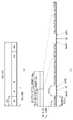
- FIG. 2illustrates a structure of a radio frame according to an embodiment.
- the first type frame structuremay be applied to both a full duplex frequency division duplex (FDD) system and a half duplex FDD (half duplex) system.
- FDDfrequency division duplex
- FDDhalf duplex FDD
- One subframeis defined as two consecutive slots, and the i-th subframe may be configured as slots corresponding to 2i and 2i + 1. That is, the radio frame may consist of 10 subframes.
- the time taken to transmit one subframeis called a transmission time interval (TTI).
- the slotmay include a plurality of OFDM symbols or SC-FDMA symbols in the time domain and may include a plurality of resource blocks in the frequency domain.
- One slotincludes a plurality of orthogonal frequency division multiplexing (OFDM) symbols in the time domain. Since the 3GPP LTE system uses OFDMA in downlink, the OFDM symbol is for representing one symbol period. The OFDM symbol may be referred to as one SC-FDMA symbol or symbol period.
- a resource blockis a resource allocation unit and includes a plurality of consecutive subcarriers in one slot.
- 10 subframesmay be used simultaneously for downlink transmission and uplink transmission during each 10ms period. At this time, uplink and downlink transmission are separated in the frequency domain.
- the terminalcannot simultaneously transmit and receive.
- the structure of the above-described radio frameis only one example, and the number of subframes included in the radio frame, the number of slots included in the subframe, and the number of OFDM symbols included in the slot may be variously changed.
- FIG. 2 (b)shows a second type frame structure (frame structure type 2).
- the second type frame structureis applied to the TDD scheme.
- the second type frameincludes a special subframe consisting of three fields: Downlink Pilot Time Slot (DwPTS), Guard Period (GP), and Uplink Pilot Time Slot (UpPTS).
- DwPTSDownlink Pilot Time Slot
- GPGuard Period
- UpPTSUplink Pilot Time Slot
- the DwPTSis used for initial cell search, synchronization or channel estimation in the terminal.
- UpPTSis used for channel estimation at the base station and synchronization of uplink transmission of the terminal.
- the guard periodis located between the uplink and the downlink, and is a section for removing interference generated in the uplink due to the multipath delay of the downlink signal.
- the same frequency bandis divided into a downlink subframe and an uplink subframe in the time domain.
- Mis the number of downlink subframes corresponding to one uplink subframe. Accordingly, the terminal transmits ACK / NACK for a plurality of PDSCHs on M downlink subframes in one uplink subframe.
- the structure of the radio frameis only an example, and the number of subframes included in the radio frame, the number of slots included in the subframe, or the number of symbols included in the slot may vary according to embodiments.
- Table 1 belowshows the structure of the special frame (length of DwPTS / GP / UpPTS).
- Xrepresents the number of additional SC-FDMA symbols in the UpPTS and may be provided by a higher layer parameter srs-UpPtsAdd. X is equal to 0 if no parameter is set.
- the UEmay perform special subframe configurations ⁇ 3, 4, 7, 8 ⁇ for general CP in downlink and special subframe configurations ⁇ 2, 3, 5, 6 ⁇ for extended CP in downlink. You may not expect two additional UpPTS SC-FDMA symbols to be set for.
- the terminalis a special subframe configurations ⁇ 1, 2, 3, 4, 6, 7, 8 ⁇ for the general CP in the downlink and special subframe configurations ⁇ 1, for the extended CP in the downlink 2, 3, 5, 6 ⁇ may not be expected to set four additional UpPTS SC-FDMA symbols.
- the UEis not expected to be configured with 2 additional UpPTS SC-FDMA symbols for special subframeconfigurations ⁇ 3, 4, 7, 8 ⁇ for normal cyclic prefix in downlink and special subframeconfigurations ⁇ 2, 3, 5, 6 ⁇ for extended cyclic prefix in downlink and 4 additional UpPTS SC-FDMA symbols for special subframeconfigurations ⁇ 1, 2, 3, 4, 6, 7, 8 ⁇ for normal cyclic prefix in downlink and special subframeconfigurations ⁇ 1, 2, 3, 5, 6 ⁇ for extended cyclic prefix in downlink.
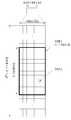
- FIG. 3is a diagram illustrating a resource grid for a downlink slot according to an embodiment.
- one downlink slotmay include a plurality of OFDM symbols in the time domain.
- one downlink slotmay include 7 OFDM symbols, and one resource block may include 12 subcarriers in the frequency domain, but is not limited thereto.
- Each element on the resource gridis referred to as a resource element, and one resource block may include 12 x 7 resource elements.
- the number NDL of resource blocks included in the downlink slotis determined by the downlink transmission bandwidth.
- FIG. 4is a diagram illustrating a structure of an uplink subframe according to an embodiment.
- a downlink subframemay be divided into a control region and a data region in the time domain, and a maximum of three (or four) subframes are located in the first slot of the subframe.
- OFDM symbolsare control regions to which control channels are allocated, and the remaining OFDM symbols are data regions to which PDSCHs are allocated.
- the downlink control channel used in the LTE systemmay include, for example, a physical control format indicator channel (PCFICH), a physical downlink control channel (PDCCH), a physical hybrid-ARQ indicator channel (PHICH), and the like, but is not limited thereto. Do not.
- the PCFICHis transmitted in the first OFDM symbol of a subframe and may carry information (eg, the size of the control region) about the number of OFDM symbols used to transmit control channels within the subframe.
- the PHICHis a response channel for the uplink, and may transmit an acknowledgment (ACK) / negative-acknowledgement (NACK) signal for a hybrid automatic repeat request (HARQ).
- control information transmitted through the PDCCHmay be referred to as downlink control information (DCI).
- the DCImay include resource allocation information and other control information for the terminal or the terminal group.
- the DCImay include downlink resource allocation information, uplink resource allocation information, or an uplink transmission (Tx) power control command for an arbitrary terminal group, but is not limited thereto.
- the transmission format and resource allocation information of a downlink shared channelmay be referred to as downlink scheduling information or a DL grant, and an uplink shared channel (UL-)
- the transmission format and resource allocation information of the SCHmay be referred to as uplink scheduling information or a UL grant.
- the DCI transmitted through one PDCCHmay vary in size and use according to the DCI format, and may vary in size according to a coding rate.
- the PDCCHis transmitted on an aggregation of one or a plurality of consecutive control channel elements (CCEs).
- CCEis a logical allocation unit used to provide a PDCCH with a coding rate based on radio channel conditions.
- the CCEcorresponds to a plurality of resource element groups (REGs).
- the format of the PDCCH and the number of PDCCH bitsare determined according to the number of CCEs.
- a set of CCEs in which a PDCCH can be locatedmay be defined for each UE.
- the set of CCEs in which the UE may discover its own PDCCHmay be referred to as a PDCCH search space or a search space (SS).
- an individual resource to which a PDCCH can be transmitted in the search spacemay be referred to as a PDCCH candidate, and a set of PDCCH candidates to be monitored by the UE may be defined as a search space.
- the size of the search spacemay vary according to embodiments, and the search space may be divided into a dedicated search space and a common search space.
- the dedicated search spacemay be referred to as a UE-specific search space (USS), and may be individually set for each terminal.
- the common search spacemay be set for a plurality of terminals.
- the base stationtransmits the actual PDCCH among any PDCCH candidates in the search space, and the terminal may monitor the search space to find the PDCCH.
- monitoringmay mean attempting to decode each PDCCH in the corresponding search space according to the monitored DCI format.
- the base stationmay determine the DCI format according to the DCI to be transmitted to the terminal, and may add a cyclic redundancy check (CRC) to the DCI.
- CRCmay be masked with an identifier (eg, a radio network temporary identifier (RNTI)) according to the owner or purpose of use of the PDCCH.
- RNTIradio network temporary identifier
- an identifiereg, cell-RNTI (C-RNTI)
- C-RNTIcell-RNTI
- a paging identifiereg, paging-RNTI (P-RNTI)
- P-RNTIpaging-RNTI
- SI-RNTIsystem information RNTI
- RA-RNTIrandom access-RNTI
- a plurality of PDCCHsmay be transmitted in the control region, and the terminal may monitor the plurality of PDCCHs.
- the UEmay detect its own PDCCH by monitoring the plurality of PDCCHs. Basically, since the UE does not know where the PDCCH is transmitted, the UE attempts to decode the PDCCH for every PDCCH of the corresponding DCI format until it detects the PDCCH having its identifier. Decoding may be referred to as blind decoding or blind detection.
- FIG. 5is a diagram illustrating a structure of a downlink subframe according to an embodiment.
- an uplink subframeincludes a plurality of slots (eg, two).
- the slotmay include different numbers of SC-FDMA symbols according to a cyclic prefix (CP) length.
- the uplink subframemay be divided into a control region and a data region in the frequency domain.
- a PUCCH for transmitting uplink control informationis allocated.
- a PUSCH carrying user datais allocated.
- One terminaldoes not simultaneously transmit the PUCCH and the PUSCH in order to maintain a single carrier characteristic.
- a PUCCH for one UEis allocated an RB (Resource Block) pair in a subframe.
- the RBs included in the RB pairoccupy different subcarriers in each of the two slots, and the RB pair allocated to the PUCCH is frequency hopping at a slot boundary.
- PUCCHmay be used to transmit control information such as scheduling request (SR), HARQ-ACK, and channel state information (CSI).
- SRscheduling request
- HARQ-ACKHARQ-ACK
- CSIchannel state information
- SRService Request
- OOKOn-Off Keying
- the HARQ-ACKmay mean a response to a PDCCH and / or a response to a downlink data packet (eg, a codeword) transmitted through a PDSCH.
- HARQ-ACKmay indicate whether the PDCCH or PDSCH has been successfully received by the UE.
- one bit of HARQ-ACKmay be transmitted in response to one downlink codeword, and two bits of HARQ-ACK may be transmitted in response to two downlink codewords.
- HARQ-ACKmay include ACK, NACK, DTX (Discontinuous Transmission) or NACK / DTX
- HARQ-ACKmay be mixed with HARQ ACK / NACK, ACK / NACK, HARQ-ACK feedback.
- Channel State Informationmay mean feedback information on a downlink channel.
- the CSImay include at least one of channel quality information (CQI), precoding matrix indicator (PMI), precoding type indicator, and rank indication (RI). have.
- CQIchannel quality information
- PMIprecoding matrix indicator
- RIrank indication
- RATsradio access technologies
- mMTCmassive machine type communications
- the new wireless access technology systemproposed as a new wireless access technology for convenience New RAT Or NR (New Radio).
- ⁇ for each carrier bandwidth part and cyclic prefix (CP) informationmay be signaled for each downlink (DL, downlink) or uplink (UL, uplink), respectively.
- ⁇ and CP information for a downlink carrier bandwidth partmay be signaled through higher layer signaling DL-BWP-mu and DL-MWP-cp.
- ⁇ and CP information for an uplink carrier bandwidth partmay be signaled through higher layer signaling UL-BWP-mu and UL-MWP-cp.
- the downlink and uplink framesmay be composed of 10 ms long frames, and one frame may be configured of 10 subframes having a 1 ms long length. In this case, the number of consecutive OFDM symbols for each subframe is to be.
- Each framemay consist of two half frames having the same size.
- the two half-framesmay be composed of subframes 0 to 4 and subframes 5 to 9, respectively.
- slotsare in ascending order within one subframe. Numbered as in ascending order within a frame It may be numbered as follows. In this case, the number of consecutive OFDM symbols in one slot ( ) May be determined according to CP as shown in Table 4 below. Start slot in one subframe ( ) Is the starting OFDM symbol () in the same subframe ) And time dimension.
- Table 4shows the number of OFDM symbols per slot / frame / subframe for a normal cyclic prefix (CP), and Table 5 shows slots / frame / sub / for an extended cyclic prefix (CP). This indicates the number of OFDM symbols per frame.
- the technical features of the NB-IoT systemwill be described in detail. For convenience of description, it will be described based on the NB-IoT based on the 3GPP LTE standard, the configuration can be equally applied to the 3GPP NR standard. To this end, some technical configurations may be interpreted by changing (eg, changing a subframe into a slot).
- the NB-IoTwill be described based on the LTE standard technology, but the LTE standard technology can be interpreted by being replaced with the NR standard technology within a range easily derivable to those skilled in the art.
- NB-IoTsupports three modes of operation: in-band, guard-band, and stand-alone. The same requirements apply to each mode.
- In-band modeallocates and manages some of the in-band resources of the LTE system to the NB-IoT system.
- the guard-band modeutilizes the guard frequency band of the LTE system, and the NB-IoT carrier is arranged as close as possible to the edge subcarrier of the LTE system.
- GSMGlobal System for Mobile Communications
- the NB-IoT terminalsearches for an anchor carrier in units of 100 kHz for initial synchronization, and the center frequency of the anchor carrier in the in-band and guard-bands should be located within ⁇ 7.5 kHz from the 100 kHz channel raster. do.
- the NB-IoT terminalmay mean a terminal operating in the NB-IoT system and a terminal supporting the NB-IoT.
- 6 PRBs among the LTE Physical Resource Blocks (PRBs)are not allocated to the NB-IoT system.
- the anchor carriermay be located only in a particular PRB.
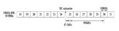
- FIG. 6is a diagram illustrating an arrangement of an anchor carrier of an in-band in an LTE system according to an embodiment.
- the Direct Current (DC) subcarrieris located in the channel raster. Since the center frequency spacing between adjacent PRBs is 180 kHz, the center frequencies of PRB indexes 4, 9, 14, 19, 30, 35, 40 and 45 are located at ⁇ 2.5 kH from the channel raster.
- the center frequency of the PRB suitable for transmission of the anchor carrieris located at ⁇ 2.5 kHz from the channel raster, and when the bandwidth is 3 MHz, 5 MHz, and 15 MHz, the center frequency of the PRB suitable for transmission of the anchor carrier is the channel. It is located at ⁇ 7.5 kHz from the raster.
- guard-band modewhen the bandwidth is 10 MHz and 20 MHz, the center frequency of the PRB immediately adjacent to the edge PRB of the LTE system is located at ⁇ 2.5 kHz from the channel raster.
- the bandwidthwhen the bandwidth is 3MHz, 5MHz, 15MHz, by using a guard frequency band corresponding to three subcarriers from the edge PRB, the center frequency of the anchor carrier can be located at ⁇ 7.5kHz from the channel raster.
- the anchor carrier in standalone modeis aligned to the 100kHz channel raster, and all GSM carriers, including DC carriers, can be utilized as NB-IoT anchor carriers.
- NB-IoTsupports multiple carrier operations, and a combination of in-band and in-band, in-band and guard-band, guard-band and guard-band, standalone and standalone may be used.
- the downlink of the NB-IoT systemuses an Orthogonal Frequency Division Multiple Access (OFDMA) scheme having a 15 kHz subcarrier spacing.
- OFDMAOrthogonal Frequency Division Multiple Access
- the OFDMA schemeprovides orthogonality between subcarriers, so that the NB-IOT system and the LTE system can coexist smoothly.
- Downlinkmay be provided with physical channels such as Narrowband Physical Broadcast Channel (NPBCH), Narrowband Physical Downlink Shared Channel (NPDSCH), Narrowband Physical Downlink Control Channel (NPDCCH), Narrowband Primary Synchronization Signal (NPSS), Narrowband Primary Synchronization Signal Physical signals such as NSSS, Narrowband Reference Signal (NRS).
- NNBCHNarrowband Physical Broadcast Channel
- NPDSCHNarrowband Physical Downlink Shared Channel
- NPDCCHNarrowband Physical Downlink Control Channel
- NPSSNarrowband Primary Synchronization Signal
- NSSSNarrowband Primary Synchronization Signal Physical signals
- Narrowband Reference SignalNarrowband Reference Signal
- FIG. 7is a diagram illustrating a location where a downlink physical channel and a downlink signal are transmitted in an LTE system operating in an FDD scheme according to an embodiment.
- an NB-IoT terminalIn order to access a network, an NB-IoT terminal should acquire system information of a cell, and in order to obtain system information of a cell, it should acquire synchronization with a cell through a cell search process. In order for the NB-IoT terminal to acquire synchronization with the cell, the synchronization signal may be transmitted in downlink.
- the NB-IoT terminalacquires frequency, symbol, and frame synchronization using a synchronization signal and searches for 504 physical cell IDs (PCIDs). Since the synchronization signal of the LTE system is transmitted through 6 PRB resources, it is impossible to reuse the synchronization signal of the LTE system to an NB-IoT system using 1 PRB.
- PCIDsphysical cell IDs
- the synchronization signals (eg, NPSS and NSSS) of the new NB-IoT systemare designed, and the synchronization signals of the NB-IoT system can be equally applied to the three operating modes of the NB-IoT.
- NPBCHis transmitted in the first subframe of each radio frame
- NPSSis in the sixth subframe of each radio frame
- NSSSis transmitted in the last subframe of each even frame.
- NPSSis composed of a ZCoff (Zadoff-Chu) sequence having a length of 11 and having 5 as a root index value.
- ZCoffZero-Chu
- NPSSmay be generated according to Equation 1 below.
- S (l) for the symbol index lmay be defined as shown in Table 6 below.
- the NSSSconsists of a combination of a binary scrambling sequence such as a ZC sequence having a length of 131 and a Hadamard sequence.
- NSSSindicates the PCID to NB-IoT terminals in the cell through the combination of the sequences.
- NSSSmay be generated according to Equation 2 below.
- Equation 2variables applied to Equation 2 may be defined as shown in Table 7 below.
- the binary sequence bq (m)may be defined as shown in Table 8 below, and the cyclic shift ⁇ f for the frame number nf may be defined as shown in Equation 3 below.
- the NRSrefers to a reference signal for channel estimation required for downlink physical channel demodulation and may be generated in the same manner as the LTE system. However, NRS uses Narrowband-Physical Cell ID (NB-PCID) as an initial value for initialization.
- NB-PCIDNarrowband-Physical Cell ID
- NRSis transmitted to one or two antenna ports, and up to two base station transmit antennas of an NB-IoT system are supported.
- the NPBCHdelivers Master Information Block-Narrowband (MIB-NB), which is the minimum system information that the NB-IoT terminal must know in order to access the system, to the terminal.
- MIB-NBMaster Information Block-Narrowband
- the transport block size (TBS) of the MIB-NBis 34 bits and is updated and transmitted every 640 ms Transmission Time Interval (TTI) period.
- TTITransmission Time Interval
- SFNSystem Frame Number
- CRSCell-specific Reference Signal
- the NPBCH signalmay be repeatedly transmitted a total of eight times to improve coverage.
- the NPDCCH channelhas the same transmission antenna configuration as the NPBCH and supports three types of downlink control information (DCI) formats (eg, DCI NO, N1, N2).
- DCI N0is used to transmit NarrowSCH Physical Uplink Shared Channel (NPUSCH) scheduling information to the UE, and DCI N1 and N2 are used to deliver information necessary for demodulating the NPDSCH to the UE.
- NPDCCHmay be repeatedly transmitted up to 2048 times to improve coverage.
- NPDSCHis a physical channel for transmitting a transport channel (TrCH) such as a downlink-shared channel (DL-SCH) and a paging channel (PCH).
- TrCHtransport channel
- DL-SCHdownlink-shared channel
- PCHpaging channel
- the maximum TBS of the NPDSCHis 680 bits, and may be repeatedly transmitted up to 2048 times to improve coverage.
- the uplink physical channelis composed of a Narrowband Physical Random Access Channel (NPRACH) and an NPUSCH, and supports single-tone and multi-tone transmission.
- NPRACHNarrowband Physical Random Access Channel
- NPUSCHNarrowband Physical Random Access Channel
- Multitone transmissionis only supported when the subcarrier spacing is 15 kHz, and single tone transmission is supported when the subcarrier spacing is 3.5 kHz and 15 kHz.
- the subcarrier spacingis 15 kHz in the uplink, since orthogonality with the LTE system can be maintained, optimal performance can be provided. However, when the subcarrier spacing is 3.75 kHz, orthogonality may be degraded and performance degradation due to interference may occur.
- the NPRACH preambleconsists of four symbol groups. Each symbol group consists of a Cyclic Prefix (CP) and five symbols. NPRACH only supports single-tone transmissions with a subcarrier spacing of 3.75 kHz and provides CPs of 66.7 ⁇ s and 266.67 ⁇ s to support different cell radii.
- CPCyclic Prefix
- Each symbol groupperforms frequency hopping.
- the subcarriers transmitting the first symbol groupare determined in a pseudo-random manner.
- the second symbol groupis one subcarrier
- the third symbol groupis six subcarriers
- the fourth symbol groupis one subcarrier jump.
- the aforementioned frequency hopping procedureis repeatedly applied, and the NPRACH preamble may be repeatedly transmitted up to 128 times in order to improve coverage.
- NPUSCHcan support two formats. Format 1 is for UL-SCH transmission, and the maximum transmission block size (TBS) is 1000 bits. Format 2 is used to transmit uplink control information such as HARQ ACK signaling. Format 1 supports single-tone and multi-tone transmissions, while Format 2 only supports single-tone transmissions. In the case of single tone transmission, binary phase shift keying (p / 2-BPSK) and quadrature phase shift keying (p / 4-QPSK) may be used to reduce the Peer-to-Average Power Ratio (PAPR).
- p / 2-BPSKbinary phase shift keying
- p / 4-QPSKquadrature phase shift keying
- all resources included in one PRBmay be allocated to the NB-IoT system.
- resource mappingis restricted in order to maintain orthogonality with signals of legacy LTE (Legacy LTE) systems.
- the NB-IoT terminalshould detect NPSS and NSSS for initial synchronization in the absence of system information. Therefore, resources classified as allocation areas for the control channel of the LTE system (OFDM symbols 0 to 2 of each subframe) cannot be allocated to the NPSS and NSSS, and are allocated to a RE (Resource Element) overlapping the CRS of the LTE system. Mapped NPSS and NSSS symbols should be punched.
- FIG. 8is a diagram illustrating resource allocation for signals of an NB-IoT system and signals of an LTE system in an in-band mode according to an embodiment.
- NPSS and NSSSregardless of the operating mode of the NB-IoT system, of the subframe corresponding to the resource region for transmitting the control channel in the conventional LTE system It is not transmitted in the first three OFDM symbols.
- Common Reference Signal (CRS) and REs for NPSS / NSSS colliding on physical resources in the existing LTE systemare punctured and mapped so as not to affect the existing LTE system.
- the NB-IoT terminalAfter the cell search, since the NB-IoT terminal demodulates the NPBCH in the absence of system information other than the PCID, the NB-IoT terminal cannot map the NPBCH symbol to the control channel allocation region of the LTE system. In addition, since four LTE antenna ports and two NB-IoT antenna ports must be assumed, REs allocated to CRSs and NRSs accordingly cannot be allocated to NPBCHs. Therefore, NPBCH needs to be rate-matched according to available resources.
- the NB-IoT terminalAfter the NPBCH demodulation, the NB-IoT terminal acquires information on the number of CRS antenna ports, but still cannot know the information on the region to which the control channel of the LTE system is allocated. Therefore, the NPDSCH transmitting SIB1 (System Information Block type 1) data is not mapped to a resource classified as an area to which the control channel of the LTE system is allocated.
- SIB1System Information Block type 1
- NPDSCH(except when transmitting SIB1) and NPDCCH are available resources. Can be mapped to
- the present inventionproposes a hybrid automatic repeat request (HARQ) -ACK feedback method for effectively controlling unnecessary repetitive transmission of uplink data of a terminal.
- the proposed methodis, for example, a machine type communication (MTC) system, an enhanced MTC (eMTC) system, an NB-IoT system using some bands of the total system bandwidth, and a system operating in a half-duplex method. It may be applied, but is not limited thereto.
- MTCmachine type communication
- eMTCenhanced MTC
- NB-IoTusing some bands of the total system bandwidth
- a system operating in a half-duplex methoda system operating in a half-duplex method.
- the MTC systemwill be described as an example.
- the scheme proposed as the HARQ-ACK feedback methodit is possible to allocate resources of RE level in units smaller than 1RB.
- the MTC systemmay be classified into a coverage enhancement (CE) mode A and a CE mode B according to the location or transmission power of the terminal, and the terminal operation performed according to the CE mode may vary.
- CE mode Bmay require a higher transmission power than CE mode A, and may require more repetitive transmission times than CE mode A for up / down link transmission / reception.
- Tables 9 and 10 belowshow the number of repetitive transmissions and the maximum number of repetitive transmissions of the PUSCH for each mode.
- the maximum number of repetitive transmissions of the PUSCHmay be 16 or 32.
- the maximum number of repetitive transmissions of the PUSCHmay be one of 192, 256, 384, 512, 768, 1024, 1536, and 2048.
- a set corresponding to each of the maximum number of repetitive transmissionsmay be defined, and the number of repetitive transmissions is based on the maximum number of repetitive transmissions and the value indicated by the DCI. It may be selected in a set corresponding to the number of transmissions.
- the maximum number of repeated transmissionsis 1024
- the value indicated by the DCIis 3
- the number of repeated transmissionscorresponds to the maximum number of repeated transmissions 1024.
- the third value(eg, 16) may be determined from the set ⁇ 4, 8, 16, 64, 128, 256, 512, 1024 ⁇ , but is not limited thereto.
- the terminalmay repeatedly transmit the PUSCH by the number of repetitive transmissions set according to a specific rule.
- the base stationmay succeed in detecting the PUSCH before the PUSCH is transmitted the set number of repetitive transmissions.
- the terminalcannot arbitrarily terminate the repeated transmission of the PUSCH before transmitting the PUSCH by the set number of repetitions. Accordingly, when the PUSCH is repeatedly transmitted unnecessarily, the terminal consumes unnecessary power, interference between neighboring cells may occur, and the base station may have difficulty in managing resources effectively.
- the terminalmay periodically or intermittently detect the HARQ-ACK information on the uplink data while repeatedly transmitting the uplink data.
- the detected HARQ feedback informationmay mean HARQ feedback information corresponding to the HARQ process number that is being repeatedly transmitted.
- a method in which a terminal repeatedly transmitting uplink dataeffectively detects HARQ feedback information, thereby reducing the number of unnecessary repeated transmissions of uplink data and power consumption of the terminal.
- the base stationmay explicitly set the interval and period in which the HARQ-ACK feedback operation is performed through a UL-grant for instructing uplink resource allocation to the terminal.
- the interval and period in which the HARQ-ACK feedback operation is performed through the UL-grantare explicitly set, there is an advantage that the HARQ-ACK feedback operation can be dynamically set for each UL-grant, but the downlink control information (DCI) There may be a drawback of increasing information.
- DCIdownlink control information
- the base stationmay set the interval and period in which the HARQ-ACK feedback operation is performed through a message of a higher layer such as an RRC message.
- the HARQ-ACK feedback information set through the upper layer messagemay be set to be valid until the next HARQ-ACK feedback information is set again through the upper layer message or may be set to expire after a specific time. .
- HARQ-ACK feedback operationmay be explicitly performed or not performed for every UL-grant.
- the HARQ-ACK feedback information set through the message of the higher layermay be information about an operation of the terminal performed under a specific condition.
- the terminalmay check a specific condition based on the information indicated by every UL-grant, and may perform a different HARQ-ACK feedback monitoring operation for detecting HARQ-ACK information according to whether the corresponding condition is satisfied.
- the specific conditionmay include, but is not limited to, at least one of CE mode, uplink repetitive transmission count, uplink transmission power, and whether the corresponding uplink data is retransmission.
- the terminalmay differently set at least one of a HARQ-ACK feedback monitoring period, an offset, and a period according to whether the corresponding condition is satisfied.
- the power consumption gain due to early termination of uplink data repetitive transmissionmay be relatively low.
- the number of repetitive transmissions of CE mode Ais relatively less than the number of repetitive transmissions of CE mode B, the number of repetitive transmissions saved by early termination of uplink data repetitive transmission may not be large.
- the benefit of early termination of uplink data transmissionis beneficial. This may not be big.
- the CE mode Btransmits an uplink signal at the maximum transmit power, and since the number of repetitive transmissions may also be relatively higher than that of the CE mode A, the power consumption gain of the UE by HARQ-ACK feedback monitoring may be large. Therefore, the base station can set the HARQ-ACK feedback operation based on the CE mode.
- the number of uplink repeated transmissions of a terminal operating according to CE mode Bis more likely than the number of uplink repeated transmissions of a terminal operating according to CE mode A.
- the number of uplink repetitive transmissions of the terminal operating in CE mode Bmay be less than the number of uplink repetitive transmissions of the terminal operating in CE mode A. Accordingly, the base station may set the HARQ-ACK feedback operation differently according to the number of uplink repetitive transmissions even in the terminals operating in the CE mode B.
- a terminal operating according to CE mode Adoes not always transmit an uplink signal at the maximum transmission power.
- the terminalmay transmit an uplink signal with a transmission power close to the maximum transmission power.
- the base stationmay differently set HARQ-ACK feedback based on at least one of the number of uplink repetitive transmissions and the uplink transmission power, even in terminals operating according to CE mode A.
- the UEattempts to detect the HARQ feedback information while repeatedly transmitting the uplink data because the base station may succeed in detecting the corresponding uplink data before the uplink data is transmitted by the number of repetitive transmissions. Therefore, the HARQ-ACK feedback monitoring operation of the terminal may be more effective when the reliability of the uplink transmission (for example, the probability that the transmitted uplink data is successfully detected by the base station) is relatively high. have. Accordingly, the HARQ-ACK feedback monitoring operation of the terminal may be set differently depending on whether the uplink transmission of the terminal is new transmission or re-transmission of the corresponding HARQ process number.
- the terminal on which the HARQ-ACK feedback is configuredneeds to detect HARQ-ACK feedback information on the uplink data while repeatedly transmitting the uplink data.
- HARQ-ACK informationmay be transmitted through a channel used for transmitting ACK information or a channel used for another purpose.
- PHICH of LTEis a channel used for transmitting ACK information
- (M) PDCCHis a channel used for transmitting downlink control information.
- HARQ feedback informationis used for PHICH or (M) PDCCH. It may be transmitted over the same or similar channel.
- the same or similar channel as the (M) PDCCHmay include a PDCCH, an MDPCCH (MTC PDCCH), or an NPDCCH (narrowband PDCCH) according to a system in which the UE operates.
- HARQ-ACK feedback informationmay be transmitted through the MPDCCH
- HARQ-ACK feedback informationis NPDCCH It may be transmitted through, but is not limited thereto. Therefore, the base station may retransmit the HARQ-ACK information more than once to support the detection of the stable HARQ-ACK information of the terminal.
- the number of retransmissions of HARQ-ACK informationmay be determined based on the received SNR of the terminal.
- the received SNR of the terminalmay be associated with at least one of the number of uplink repetitive transmission, uplink transmission power, modulation and coding scheme (MCS), and the number of repetitive retransmissions of HARQ-ACK information is HARQ-ACK feedback monitoring. It may be associated with at least one of a period, an offset, and a period. Accordingly, at least one of the HARQ-ACK feedback monitoring period, offset, and interval may be determined based on at least one of the number of uplink repeated transmissions, uplink transmission power, and MCS.
- MCSmodulation and coding scheme
- Second proposalmethod of transmitting HARQ-ACK information
- a new channel(eg, PHICH-based channel of LTE) may be designed or an existing (M) PDCCH-based channel may be used.
- Mexisting
- the (M) PDCCH-based channelmay be designed to include a DCI of the same size as the existing DCI (eg, DCI format 6-0A / B) or a DCI of a size smaller than the existing DCI.
- a DCI of the same size as the existing DCIeg, DCI format 6-0A / B
- a DCI of a size smaller than the existing DCIe.g., DCI format 6-0A / B
- the informationmay be used to deliver HARQ-ACK information to a plurality of terminals by one signaling or to transmit HARQ-ACK information for a plurality of uplink HARQ process numbers to one terminal.
- (M) PDCCH including the DCI of the same size as the existing DCIthere is an advantage that does not increase the complexity of the terminal for blind detection (b), but the new information without causing confusion to the terminal In addition it can be difficult to transmit.
- the base stationuses the unused state (invalid state, invalid state) of the resource allocation field (M) PDCCH and the Modulation and Coding Scheme (MCS) field of the (M) PDCCH, to the terminal in one DCI transmission HARQ-ACK information for a plurality of HARQ process numbers may be transmitted.
- the base stationmay transmit HARQ-ACK information by using an unused state according to each CE mode.
- eMTCenhanced machine type communication
- the resource block assignment field of DCI format 6-0Ahas the number of bits ⁇ 5, 6, 7, 8, 9, 9 ⁇ depending on the system bandwidth ⁇ 1.4, 3, 5, 10, 15, 20 ⁇ MHz. Can be assigned, in all cases at least 11 states are not used.
- the MCS fieldis composed of 4 bits and may include 16 states.
- five states corresponding to 11 to 15(for example, binary 1011 to 1111) are not used among the 16 states corresponding to 0 to 15 (for example, binary 0000 to 1111). .
- the terminal(or terminal group), according to the existing method, based on an already acquired Cell Radio Network Temporary Identifier (C-RNTI) (specific RNTI that can be shared by the terminal group in the case of the terminal group).
- C-RNTICell Radio Network Temporary Identifier
- M) PDCCH DCI format 6-0A (or 6-0B)may be blind detected. If a value corresponding to an unused state is allocated to the resource block allocation field (the MCS field in the case of DCI format 6-0B) of the detected DCI, the terminal may interpret the corresponding DCI as a DCI for HARQ-ACK feedback. have. In this case, in order to specify the HARQ-ACK feedback usage, a specific value may be specified among values corresponding to eleven states (five states in the case of DCI format 6-0B). Therefore, the terminal may interpret the DCI differently according to the value of the unused state.
- C-RNTICell Radio Network Temporary Identifier
- the base stationmay transmit HARQ-ACK information for the plurality of HARQ process numbers using the remaining bits (for example, 19 in the case of DCI format 6-0A).
- the base stationmay transmit HARQ-ACK information for a plurality of HARQ process numbers by applying a bit map form to the remaining bits, but is not limited thereto.
- the base stationmay allocate 8 bits to each HARQ process and transmit ACK / NACK to 0/1, respectively.
- the base stationmay be designed such that the ACK / NACK of each HARQ process has a specific relationship (for example, a channel coding method) in order to improve reliability of the ACK / NACK.
- ACK informationcan be transmitted.
- the base stationbundles a plurality of HARQ process numbers into one group and transmits HARQ-ACK information. Can transmit When bundling a plurality of HARQ process numbers into one group, there is an advantage in that the minimum bit necessary for informing ACK / NACK combinations for N HARQ processes at a time can be easily obtained.
- the UEwhen repeatedly transmitting N HARQ processes in uplink at the same time, when specific M ( ⁇ N) HARQ processes have already been detected as ACKs by the base station, the UE performs M HARQ processes with one (M) PDCCH monitoring. Uplink transmission of the can be stopped. In addition, the UE may stop ACK / NACK monitoring or (M) PDCCH monitoring for M HARQ processes.
- the number N of HARQ processes through which HARQ-ACK information is transmitted through the (M) PDCCHis selected from the maximum number of HARQs in the corresponding CE mode, the number of HARQ processes scheduled in uplink, or the number of HARQ processes scheduled in uplink. It may be equal to the number of HARQ processes that do not receive an ACK feedback until a specific time. Also, exceptionally, if a UL channel (e.g., (N) PUSCH transmitting only PUCCH or aperiodic CSI) without special restriction on HARQ process number is repeatedly transmitted, the (N + a) th HARQ It may be indicated further by the process number. In this case, a may be 1, but is not limited thereto.
- the (N) PUSCHmay include a PUSCH or an NPUSCH according to a system in which the UE operates, but is not limited thereto.
- the terminalis a terminal operating in the eMTC system (N) PUSCH may be a PUSCH
- when the terminal is a terminal operating in the NB-IOT system (N) PUSCHmay be a narrowband PUSCH (NPUSCH).
- the UEshould continuously transmit an uplink to an HARQ process that has not received an ACK among N or (N + a) HARQ processes, and may operate according to a non-adaptive HARQ scheme.
- an HARQ process that has not received an ACK feedbackmay continue to be transmitted uplink using an initially set MCS and RV.
- the RVmay follow a specific RV pattern used for retransmission of the corresponding MCS.
- bits left after transmitting HARQ-ACK for N or (N + a) HARQ processesare used for uplink transmission methods (eg, MCS, number of repetitive transmissions, uplinks) for other HARQ processes that have not received ACK feedback. Link resources, etc.).
- the above-described DCI formats 6-0A and 6-0Bmay be replaced with 6-1A and 6-1B, respectively, and a method of transmitting HARQ-ACK information and a method of interpreting DCI may vary according to FDD or TDD. .
- a DCI including an unused statemay be used to transmit HARQ-ACK information in a manner similar to that described above.
- the above-described methodmay be applied to the NB-IoT system and may support HARQ-ACK feedback operation for early termination of uplink data transmission in the NB-IoT system.
- a downlink subframe and an uplink subframemay appear alternately at a specific period.
- the UEcan expect the ACK for the (N) PUSCH that was being transmitted in the downlink subframe # interval appearing during the repeated transmission of the scheduled (N) PUSCH.
- the MCS field and subcarrier indication field of the UL grantmay include one or more unused states.
- the base stationmay feed back HARQ-ACK information for a plurality of uplink HARQ processes as well as HARQ-ACK information for one uplink HARQ process using an unused state of the MCS field and the subcarrier indication field.
- the MCS of the UL grant(DCI NO) is composed of 4 bits, and among 16 states including 0 to 15, a state corresponding to 11 to 15 is not defined.
- the 6-bit subcarrier indication fieldhas a subcarrier spacing of 15 kHz, and a state corresponding to 19 to 63 of 64 states including 0 to 63 is not used, and the subcarrier spacing is 3.75 kHz. , States 48-63 are not used.
- the UEmay interpret HARQ-ACK information for a specific uplink HARQ process as ACK. Accordingly, the base station may inform the terminal that the scheduling of the previously transmitted NPUSCH was the last scheduling without explicitly scheduling a new NPUSCH using the unused state of the MCS field or the subcarrier spacing field.
- ACK / NACKmay be defined by joint coding unused states of the MCS field and the subcarrier indication field.
- the value of the ⁇ MCS, subcarrier indication ⁇ field combinationis ⁇ 11, 48 ⁇ , it is defined as ACK for uplink HARQ process # 1 and NACK for uplink HARQ process # 1 when ⁇ 11, 49 ⁇ .
- the value of the ⁇ MCS, subcarrier indication ⁇ field combinationis ⁇ 12, 48 ⁇ , it can be defined as ACK for uplink HARQ process # 2 and NACK for uplink HARQ process # 2 when ⁇ 12, 49 ⁇ .
- ACK / ACK for uplink HARQ processes 1 and 2 when ⁇ 13, 48 ⁇ , and ACK / NACK for 1 and 2 for uplink HARQ processes when ⁇ 13, 49 ⁇ , ⁇ 13, 50 ⁇ when the NACK / ACK for the uplink HARQ process 1 and 2, respectively, and uplink HARQ process 1 and 2 when the ⁇ 13, 51 ⁇can be defined as NACK / NACK, respectively, It is not limited to this. Therefore, as a specific value of the aforementioned ⁇ MCS, subcarrier indication ⁇ field combination, another value may be used among values corresponding to unused states.
- the terminalwhen receiving a NACK feedback for a specific uplink HARQ process, the terminal may be interpreted to continue to transmit the corresponding uplink HARQ process previously transmitted. However, when receiving an ACK feedback for one HARQ process, the UE may additionally or selectively transmit an uplink HARQ process that receives NACK or ACK does not receive feedback using a resource allocated to the corresponding HARQ process.
- the MCS fieldis used to feed back HARQ-ACK information
- the subcarrier indication fieldmay be used to set the RV of the NPUSCH transmission when NACK. have.
- joint codingin order to change the RV and the modulation order of retransmission (or subsequent NPUSCH transmission) for the uplink HARQ process with NACK feedback, joint coding may be used.
- interpretation of all remaining fields of DCI N0may vary, and the DCI format and the value of an unused state may vary depending on the system. have.
- RE-level uplink scheduling at a Resource Element (RE) level smaller than 1 RB (Resource Block)is possible.
- REResource Element
- itmay be limited to support only QPSK regardless of the CE mode.
- a resource allocation unit (eg, number of REs or subcarriers) of the RE levelmay be set in a set including numbers smaller than 12, such as ⁇ 1, 2, 3, 6 ⁇ , and the like.
- ⁇ 1, 3, 6 ⁇is a scheduling unit of RE level smaller than 12 allowed in the NB-IoT system, and may be set to other values besides 1, 3, and 6 according to an embodiment.
- the unused statemay include some states of the MCS and some states of the resource allocation field.
- DCI formats 6-1A and 6-1BIn addition, in order to match the same size as DCI formats 6-1A and 6-1B, zero-padding added at the end of part of the payload in DCI formats 6-0A and 6-0B is applied to RE-level resource allocation. Can be used.
- a method of uplink scheduling at the RE level using the MCS field and the resource allocation fieldwill be described in detail.
- the terminalinterprets the uplink scheduling of the RE level and, in a specific RE of the RB indicated by the resource block allocation field, 1 RE or a preset value M REs can be transmitted.
- the 5-bit RB-allocation( ⁇ 0, 1, 2, ..., 31 ⁇ ) sets the starting position of the RE bundle composed of three REs to ⁇ 0, 3, 6,... , 69,... , 93 ⁇ .
- ⁇ 0, 3, 6,... , 69,... , 93 ⁇may be set such that a value greater than 69 is not used.
- the HARQ process number field of the DCImay be used.
- up to eight HARQ processesmay not be required.
- HARQ process numbers 0-3are the first HARQ processes and ⁇ 0, 1,... , 3 ⁇ can be used as TBS information (ITBS)
- HARQ process number 4-7is the second HARQ process and ⁇ 4, 5,... , 7 ⁇ may be utilized as TBS information (ITBS).
- ITBSTBS information
- some of the eight HARQ processesmay be designated and used for uplink scheduling in units of partial RBs.
- the HARQ process number designated for uplink scheduling in units of partial RBsmay be set in an upper layer. If uplink scheduling is specified in units of partial RBs, a more diverse combination of RE levels may be required. Therefore, by combining 4 bits of the existing MCS field and 5 bits of the RB allocation field, it is possible to indicate resource allocation of modulation order ⁇ QPSK, 16QAM ⁇ , TBS 'information (ITBS), and RE level.
- the above-described methodcan be equally applied to the following CE mode B, where the modulation order can be fixed to QPSK.
- Partial RB scheduling for CE mode Bmay be set in a similar manner to CE mode A, but the unused state may differ from CE mode A for each field.
- the terminalmay interpret the partial RB scheduling.
- a value between 11 and 15may be used as specific TBS information (ITBS), respectively.
- the UEmay interpret 3 bits for RB allocation in a narrow band as resource allocation at the RE level.
- a method similar to CE mode Amay be applied, or, according to an embodiment, the positions of the RBs that can be allocated in units of partial RBs are determined in a specific R number within a narrow band. If limited to RB, a method similar to CE mode A in R RBs may be applied.
- the eMTC terminalmay support more than one HARQ process, but the NB-IoT terminal may support only one HARQ process.
- the eMTC terminalcan support all of FD (Full Duplex) -FDD, HD (Half Duplex) -FDD, TDD, NB-IoT terminal can only support HD-FDD, NB-IoT terminal that supports TDD It will be introduced in the Release 15 standard.
- Not monitoring the (N) PDCCH in downlinkmay be a general operation. Therefore, in order to monitor the (N) PDCCH or the explicit ACK / NACK in consideration of the possibility that the base station passes the CRC check before receiving the (N) PUSCH transmitted N uplinks, It is necessary to stop transmission of the (N) PUSCH and monitor the downlink HARQ-ACK feedback channel (eg, (N) PDCCH, explicit ACK / NACK channel, or signal).
- the downlink HARQ-ACK feedback channeleg, (N) PDCCH, explicit ACK / NACK channel, or signal.
- the HARQ-ACK feedback monitoring operationmay increase power consumption of the terminal, and delay may occur due to the HARQ-ACK feedback monitoring operation. Can be. Accordingly, the terminal (especially, a terminal performing an HD-FDD operation) may not perform HARQ feedback monitoring when a specific condition is not satisfied, and the base station also transmits N times by the terminal without transmitting HARQ-ACK information. (N) PUSCH can continue to be received.
- a condition for not performing HARQ-ACK feedback monitoringmay be set to "before transmitting (N) PUSCH a number of times corresponding to a specific ratio of the number of repeated transmissions N", and the specific ratio is set by the base station. It may be assigned to a specific value by the standard.
- the specific ratiomay include CE mode, CE level, RSRP (Reference Signal Received Power), RSRQ (Reference Signal Received Quality), (N) PUSCH scheduling information (e.g., MCS, resource allocation information, etc.), and transfer. It may vary depending on at least one of the rates of receiving or transmitting ACK / NACK.
- RSRPReference Signal Received Power
- RSRQReference Signal Received Quality
- NPUSCH scheduling information (e.g., MCS, resource allocation information, etc.), and transfer. It may vary depending on at least one of the rates of receiving or transmitting ACK / NACK.
- the base stationmay be configured to transmit the feedback information to the terminal only when the feedback information is ACK.
- the terminalmay determine that the wrong detection, and may ignore the detected NACK. Accordingly, the HARQ-ACK feedback monitoring may be used for stopping transmission of the scheduled (N) PUSCH before N repeat transmissions of the (N) PUSCH are completed.
- the base stationin order for the base station to feed back the NACK through the HARQ-ACK feedback monitoring, other purposes other than early termination of uplink data transmission need to be accompanied.
- the base stationfeeds back the NACK through the HARQ-ACK feedback monitoring, thereby changing at least one of the RV, the modulation order, and the resource allocation of the (N) PUSCH that the UE was transmitting before the HARQ-ACK feedback monitoring in a predetermined manner.
- uplink datamay be continuously transmitted according to information rescheduled directly by HARQ-ACK feedback monitoring.
- the above-described methodmay be equally or similarly applied to a terminal operating according to FD-FDD or TDD as well as a terminal operating according to HD-FDD.
- the search spaceis a specific interval derived from the scheduled number of repeated transmissions.
- the number of repetitive transmissionsis N
- the base stationdoes not set the corresponding search space, or the corresponding search space by the base station Even if this is set, the terminal may ignore the search space.
- the specific ratio and search spacemay be set differently according to at least one of ⁇ CE mode, uplink repetitive transmission number, uplink transmission power, and whether the corresponding uplink is retransmitted ⁇ .
- the search spacemay be defined based on at least one parameter of ⁇ HARQ feedback monitoring period, offset, interval ⁇ .
- a search space (or monitoring opportunity) for early termination of uplink data transmission and / or early termination of (M) PDCCH / NPDCCH monitoringis newly defined, a specific ratio of the number of repetitive transmissions N in the corresponding search space is defined. If the (N) PUSCH is not transmitted the number of times corresponding to the UE, the UE may ignore or not receive the corresponding search space.
- a search space for monitoring HARQ-ACK feedbackmay not be set according to the number of repetitive transmissions of the scheduled (N) PUSCH. For example, when the number of repetitive transmissions of the scheduled (N) PUSCH is smaller than a specific value, a search space for monitoring HARQ-ACK feedback may not be defined.
- the UEdoes not repeatedly transmit the (N) PUSCH by a specific number of times, or the number of repeated transmissions is equal to the scheduled number of (N) PUSCH repeated transmissions. In the case of repetitively transmitting the number of times less than a certain ratio, the UE may not monitor or ignore the HARQ-ACK feedback in the corresponding search space.
- the search space for monitoring the HARQ-ACK feedbackmay be set differently according to the number of repetitive transmission of the scheduled (N) PUSCH. For example, when the number of repetitive transmissions of the (N) PUSCH is 2048 and 512, the length of the search space for monitoring each (early) HARQ-ACK may be set to be proportional to the number of repetitive transmissions.
- the search space for monitoring HARQ-ACK feedbackmay be determined based on the (maximum) number of repetitive transmissions or r max (or R max ) of the UE-specific Search Space (USS) of the terminal. .
- the above-described methodmay be applied for early termination of downlink data transmission.
- the terminalmay feed back an ACK for the corresponding downlink process through uplink transmission before transmission of scheduled downlink data is completed.
- the UEmay not be allowed to feed back the ACK before receiving the (N) PDSCH by the number corresponding to a specific ratio of K. have.
- feeding back the ACKmay mean feeding back the ACK for the corresponding downlink process before the scheduled downlink data transmission is completed.
- the NACKmay not be explicitly fed back.
- the base stationdetermines that the ACK after the terminal has received the (N) PDSCH a number of times corresponding to a specific ratio of K, but did not detect this as the DTX (Discontinuous Transmission) of the ACK, and the NACK Can be considered.
- the base stationmay reschedule the same process number of the (N) PDSCH that was being transmitted with a parameter different from the previous transmission scheduling.
- the UEmay expect that the downlink process will be transmitted in a different pattern from that originally scheduled by the base station after a specific time. Can be.
- the patternmay include at least one of a transmission power, an RV, a modulation order, an increased number of repetitive transmissions, and a precoding matrix indicator (PMI), but is not limited thereto.
- PMIprecoding matrix indicator
- FIG. 9is a flowchart illustrating a method of transmitting and receiving a signal with a base station by a terminal according to an embodiment.
- the terminal and the base stationmay operate according to a full duplex-frequency division duplex (FD-FDD) scheme or a time division duplex (TDD) scheme.
- FD-FDDfull duplex-frequency division duplex
- TDDtime division duplex
- the terminal and the base stationmay operate in a machine type communication (MTC) or narrow band-Internet of things (NB-IoT) system, but is not limited thereto.
- MTCmachine type communication
- NB-IoTnarrow band-Internet of things
- the terminalmay transmit a PUSCH to the base station.
- the UEmay repeatedly transmit the PUSCH at least once from the number of repetitive transmissions set for the PUSCH.
- the UEmay receive HARQ-ACK information on the PUSCH from the base station before transmitting the PUSCH by the number of repetitive transmissions corresponding to the PUSCH.
- the HARQ-ACK informationmay be information that can be used to terminate the transmission of the PUSCH early before transmitting the PUSCH by the number of repetitive transmissions.
- the HARQ-ACK informationmay be transmitted through an uplink grant used to indicate uplink scheduling information or may be transmitted through a DCI.
- DCIDownlink Control Channel
- one or more states in DCImay be used to indicate HARQ-ACK feedback for the PUSCH being transmitted.
- the state used to indicate the HARQ-ACK feedbackmay be a state that is not previously used or defined among a plurality of states in the DCI.
- the uplink grant or DCImay be transmitted through the MPDCCH.
- the DCIWhen HARQ-ACK information is transmitted through DCI, the DCI may have the same size as DCI formats 6-0A and 6-0B.
- HARQ-ACK informationwhen HARQ-ACK information is transmitted through the DCI, HARQ-ACK information may be transmitted through the DCI of different formats according to the CE mode of the terminal. For example, depending on the CE mode of the terminal, one or more states may be used for transmission of HARQ-ACK information in a resource allocation field of DCI format 6-0A or an MCS field of DCI format 6-0B.
- the terminalwhen the terminal operates in accordance with CE mode A, at least one state in the resource allocation field of DCI format 6-0A is used to indicate HARQ-ACK feedback for the PUSCH, the terminal operates in accordance with CE mode B In this case, one or more states in the Modulation and Coding Scheme (MCS) field included in DCI format 6-0B may be used to indicate HARQ-ACK feedback for the PUSCH.
- MCSModulation and Coding Scheme
- one or more states in the MCS field and the subcarrier indication field of the DCImay be used to indicate HARQ-ACK feedback for the PUSCH.
- the HARQ-ACK information that the terminal receives from the base stationmay include HARQ-ACK information for a plurality of HARQ processes.
- HARQ-ACK informationfor a plurality of HARQ processes.
- the UEmay receive HARQ-ACK information after transmitting the PUSCH more than the number of times corresponding to a preset ratio of the repetitive transmission times set for the PUSCH being transmitted.
- the terminalmay determine whether to terminate the transmission of the PUSCH based on the received HARQ-ACK information.
- the UEmay terminate the repeated transmission of the PUSCH before transmitting the PUSCH by the number of repetitive transmissions set for the PUSCH. Accordingly, even when the PUSCH is transmitted as many times as the number of repetitive transmissions set for the PUSCH, if the ACK for the PUSCH is feedback from the base station, the transmission for the PUSCH may be terminated early. Accordingly, the terminal can reduce power used for repeatedly transmitting unnecessary uplink data, and the base station can more efficiently manage radio resources.
- FIG. 10is a diagram illustrating a configuration of a terminal according to an embodiment.
- the terminal 100 illustrated in FIG. 10may perform a signal transmission / reception operation of the terminal illustrated in FIGS. 1 to 9.
- the terminal 100may operate as a transmitting end in the uplink and may operate as a receiving end in the downlink.
- the terminal 100may include a transceiver 110 and a processor 120.
- the terminal 100may be implemented by more components than the illustrated components, or two or more components may be combined and implemented by one component.
- the terminal 100may further include a memory in addition to the transceiver 110 and the processor 120, and may further include an antenna.
- the transceiver 110may be implemented by being separated into a transmitter and a receiver.
- the transceiver 110operates in connection with the processor 120, receives a signal from an external device (eg, a base station), and transmits a signal to the external device.
- an external deviceeg, a base station
- the transceiver 110 of the terminal 100includes a packet modulation and demodulation function for transmitting and receiving data, a fast packet channel coding function, an orthogonal frequency division multiple access (OFDMA) packet scheduling, At least one of a time division duplex (TDD) packet scheduling and / or channel multiplexing function may be performed, but is not limited thereto.
- the terminal 100 and the base station 200may further include a low power RF (Radio Frequency) / IF (Intermediate Frequency) module.
- the processor 120controls the overall operation of the terminal 100.
- the processor 120controls the transceiver to transmit the PUSCH to the base station, and controls the transceiver to receive HARQ-ACK information on the PUSCH from the base station before transmitting the PUSCH by the number of repetitive transmissions corresponding to the PUSCH. Then, it may be determined whether to terminate the transmission of the PUSCH based on the received HARQ-ACK information.
- the terminal 100may be a terminal operating in an eMTC or NB-IoT system, and when the terminal 100 is a terminal operating in an NB-IOT system, the PUSCH may mean an NPUSCH.
- HARQ-ACK informationmay be transmitted through an uplink grant used to indicate DCI or uplink scheduling information, and the DCI or uplink grant may be transmitted through MPDCCH or NPDCCH.
- the DCI or uplink grantmay be transmitted through the MPDCCH
- the terminal 100is a terminal operating in the NB-IoT system
- the DCI or uplink The link grantmay be transmitted on the NPDCCH.
- the terminal 100may include a personal digital assistant (PDA), a cellular phone, a personal communication service (PCS) phone, and a global system for mobile (GSM).
- PDApersonal digital assistant
- PCSpersonal communication service
- GSMglobal system for mobile
- WCDMAWideband CDMA
- MBSMobile Broadband System
- MM-MBMulti-Mode Multi-band
- a smart phoneis a terminal that combines the advantages of a mobile communication terminal and a personal portable terminal, and includes a terminal incorporating data communication functions such as schedule management, fax transmission and reception, which are functions of a personal mobile terminal, in a mobile communication terminal. Can mean.
- multi-mode multiband terminalshave a built-in multi-modem chip to operate in both portable Internet systems and other mobile communication systems (e.g., code division multiple access (CDMA) 2000 systems, wideband CDMA (WCDMA) systems, etc.). It can mean a terminal that can.
- CDMAcode division multiple access
- WCDMAwideband CDMA
- FIG. 11is a diagram illustrating a configuration of a base station according to an embodiment.
- the base station 200 illustrated in FIG. 11may perform signal transmission / reception of the base stations illustrated in FIGS. 1 to 9.
- Base station 200may include a transceiver 210 and a processor 220.
- the base station 200may be implemented by more components than the illustrated components, or two or more components may be combined and implemented by one component.
- the base station 200may further include a memory in addition to the transceiver 210 and the processor 220, and may further include an antenna.
- the transceiver 210may operate in connection with the processor 220 and control transmission and reception of signals, information, data, and / or messages.
- the processor 220may control the transceiver 210 to receive a PUSCH from a terminal, determine HARQ-ACK information for the PUSCH, and determine the number of repetitive transmissions corresponding to the PUSCH before receiving the PUSCH.
- HARQ-ACK informationmay be transmitted to the terminal.
- Embodiments of the inventionmay be implemented through various means.
- embodiments of the present inventionmay be implemented by hardware, firmware, software, or a combination thereof.
- the inventionWhen implemented through hardware, the invention provides one or more application specific integrated circuits (ASICs), digital signal processors (DSPs), digital signal processing devices (DSPDs), programmable logic devices (PLDs), field programmable gate arrays (FPGAs). ), A processor, a controller, a micro controller, a micro-processor, and the like, but are not limited thereto.
- ASICsapplication specific integrated circuits
- DSPsdigital signal processors
- DSPDsdigital signal processing devices
- PLDsprogrammable logic devices
- FPGAsfield programmable gate arrays
- a processora controller, a micro controller, a micro-processor, and the like, but are not limited thereto.
- the present inventionmay be implemented in the form of a module, procedure, or function that performs the above-described functions or operations.
- a program including a module, a procedure, or a function that performs the above-described functions or operationsmay be stored in a memory and executed by the processors 120 and 220.
- Embodiments of the present inventioncan be applied to various wireless access systems.
- wireless access systemsmay include a 3rd generation partnership project (3GPP) or a 3GPP2 system, but are not limited thereto.
- 3GPP3rd generation partnership project
- Embodiments of the present inventioncan be applied not only to the above-described radio access system but also to all technical fields to which the above-described radio access system is applied.
Landscapes
- Engineering & Computer Science (AREA)
- Computer Networks & Wireless Communication (AREA)
- Signal Processing (AREA)
- Mobile Radio Communication Systems (AREA)
Abstract
Description
Translated fromKorean이하의 설명은 무선 통신 시스템에 대한 것으로, 무선 통신 시스템에서 단말과 기지국 간 신호를 송수신하는 방법 및 이를 지원하는 장치에 대한 것이다.The following description relates to a wireless communication system, and a method for transmitting and receiving a signal between a terminal and a base station in a wireless communication system and an apparatus supporting the same.
무선 접속 시스템이 음성 또는 데이터 등과 같은 다양한 종류의 통신 서비스를 제공하기 위해 광범위하게 전개되고 있다. 일반적으로 무선 접속 시스템은 가용한 시스템 자원(대역폭, 전송 파워 등)을 공유하여 다중 사용자와의 통신을 지원할 수 있는 다중 접속(multiple access) 시스템이다. 예를 들어, 다중 접속 시스템은 CDMA(code division multiple access) 시스템, FDMA(frequency division multiple access) 시스템, TDMA(time division multiple access) 시스템, OFDMA(orthogonal frequency division multiple access) 시스템, SC-FDMA(single carrier frequency division multiple access) 시스템 등을 포함할 수 있다.Wireless access systems are widely deployed to provide various kinds of communication services such as voice or data. In general, a wireless access system is a multiple access system capable of supporting communication with multiple users by sharing available system resources (bandwidth, transmission power, etc.). For example, the multiple access system may include a code division multiple access (CDMA) system, a frequency division multiple access (FDMA) system, a time division multiple access (TDMA) system, an orthogonal frequency division multiple access (OFDMA) system, and a single SC-FDMA (single) system. carrier frequency division multiple access) systems, and the like.
본 발명은 PUSCH(physical uplink shared channel)에 대해 설정된 반복 전송 횟수만큼 PUSCH가 전송되기 전에 PUSCH에 대한 HARQ-ACK(hybrid automatic repeat request-acknowledgement) 피드백 동작을 수행함으로써, 불필요한 상향링크 데이터의 반복 전송을 줄이기 위한 것이다.The present invention performs a hybrid automatic repeat request-acknowledgement (HARQ-ACK) feedback operation on a PUSCH before the PUSCH is transmitted as many times as the number of repetitive transmissions set for a physical uplink shared channel (PUSCH), thereby performing unnecessary transmission of unnecessary uplink data. It is to reduce.
본 발명에서 이루고자 하는 기술적 목적들은 이상에서 언급한 사항들로 제한되지 않으며, 언급하지 않은 또 다른 기술적 과제들은 이하 설명할 본 발명의 실시예들로부터 본 발명이 속하는 기술분야에서 통상의 지식을 가진 자에 의해 고려될 수 있다.Technical objects to be achieved in the present invention are not limited to the above-mentioned matters, and other technical problems which are not mentioned are those skilled in the art from the embodiments of the present invention to be described below. Can be considered.
본 발명은 무선 통신 시스템에서 단말과 기지국이 신호를 송수신하는 방법 및 이를 지원하는 장치들을 제공한다.The present invention provides a method for transmitting and receiving signals between a terminal and a base station in a wireless communication system, and apparatuses for supporting the same.
일 실시예에 따른 무선 통신 시스템에서 단말이 기지국과 신호를 송수신하는 방법은, PUSCH를 기지국으로 전송하는 단계, PUSCH에 대응하는 반복 전송 횟수만큼 PUSCH를 전송하기 전에 PUSCH에 대한 HARQ-ACK 정보를 기지국으로부터 수신하는 단계, 및 수신된 HARQ-ACK 정보에 기초하여 PUSCH의 전송을 종료할 것인지 여부를 결정하는 단계를 포함할 수 있다.In a wireless communication system according to an embodiment of the present invention, a method for a UE to transmit / receive a signal with a base station includes transmitting a PUSCH to a base station and transmitting HARQ-ACK information on the PUSCH before transmitting the PUSCH by the number of repetitive transmissions corresponding to the PUSCH. And determining whether to terminate the transmission of the PUSCH based on the received HARQ-ACK information.
일 실시예에 따른 HARQ-ACK 정보는, DCI(Downlink Control Information) 또는 상향링크 스케줄링 정보를 지시하기 위해 사용되는 상향링크 그랜트(uplink grant)를 통해 전송되고, DCI 또는 상향링크 그랜트는 MPDCCH(machine type communication physical downlink control channel) 또는 NPDCCH(narrowband physical downlink control channel)를 통해 전송될 수 있다.HARQ-ACK information according to an embodiment is transmitted through an uplink grant used to indicate downlink control information (DCI) or uplink scheduling information, and the DCI or uplink grant is a machine type (MPDCCH). It may be transmitted through a communication physical downlink control channel (NPDCCH) or a narrowband physical downlink control channel (NPDCCH).
일 실시예에 따른 HARQ-ACK 정보가 DCI를 통해 전송될 때, DCI에서 하나 이상의 상태는 PUSCSH에 대한 HARQ-ACK 피드백을 지시하기 위해 사용될 수 있다.When HARQ-ACK information according to an embodiment is transmitted through DCI, one or more states in DCI may be used to indicate HARQ-ACK feedback for PUSCSH.
일 실시예에 따른 HARQ-ACK 정보가 DCI를 통해 전송될 때, DCI는 DCI 포맷 6-0A 또는 6-0B와 동일한 크기를 가지는 수 있다.When HARQ-ACK information is transmitted through DCI according to an embodiment, DCI may have the same size as DCI format 6-0A or 6-0B.
일 실시예에 따른 HARQ-ACK 정보가 DCI를 통해 전송될 때, HARQ-ACK 정보는 단말의 CE(Coverage Enhancement) 모드에 따라 서로 다른 포맷의 DCI를 통해 전송되고, 단말이 CE 모드 A에 따라 동작할 때, DCI 포맷 6-0A의 자원 할당(resource assignment) 필드에서 하나 이상의 상태는 PUSCH에 대한 HARQ-ACK 피드백을 지시하기 위해 사용되고, 단말이 CE 모드 B에 따라 동작할 때, DCI 포맷 6-0B에 포함되는 MCS (Modulation and Coding Scheme) 필드에서 하나 이상의 상태는 PUSCH에 대한 HARQ-ACK 피드백을 지시하기 위해 사용될 수 있다.When HARQ-ACK information is transmitted through DCI according to an embodiment, HARQ-ACK information is transmitted through DCI of different formats according to a Coverage Enhancement (CE) mode of the terminal, and the terminal operates according to CE mode A. In this case, one or more states in a resource assignment field of DCI format 6-0A are used to indicate HARQ-ACK feedback for the PUSCH, and when the UE operates according to CE mode B, DCI format 6-0B One or more states in the Modulation and Coding Scheme (MCS) field included in may be used to indicate HARQ-ACK feedback for the PUSCH.
일 실시예에 따른 단말은 FD-FDD(full duplex-frequency division duplex) 방식 또는 TDD(time division duplex) 방식에 따라 동작하는 단말일 수 있다.The terminal according to an embodiment may be a terminal operating according to a full duplex-frequency division duplex (FD-FDD) scheme or a time division duplex (TDD) scheme.
일 실시예에 따른 신호 송수신 방법은, 상향링크 그랜트 또는 상위 계층 메시지로부터 HARQ-ACK 피드백이 수행되는 구간, 주기, 및 조건 중 적어도 하나에 관한 정보를 획득하는 단계, 및 획득된 정보에 기초하여 HARQ-ACK 피드백을 수행하는 단계를 더 포함할 수 있다.According to an embodiment, a signal transmission and reception method includes obtaining information on at least one of a period, a period, and a condition in which HARQ-ACK feedback is performed from an uplink grant or an upper layer message, and based on the obtained information The method may further include performing an ACK feedback.
일 실시예에 따라 HARQ-ACK 피드백 동작이 수행되는 조건은 CE 모드, 상향링크 반복 전송 횟수, 상향링크 송신 전력, 재전송인지 여부에 관한 조건 중 적어도 하나를 포함할 수 있다.According to an embodiment, the condition under which the HARQ-ACK feedback operation is performed may include at least one of a CE mode, a number of uplink repetitive transmissions, uplink transmission power, and retransmission.
일 실시예에 따른 HARQ-ACK 정보를 수신하는 단계는 복수의 HARQ 프로세스에 대한 HARQ-ACK 정보를 수신하는 단계를 포함하고, 복수의 HARQ 프로세스에 대한 HARQ-ACK 정보를 수신하는 단계는, HARQ-ACK 정보를 전송하기 위해 사용되는 비트 수가 HARQ 프로세스 수보다 적을 때, 복수의 HARQ 프로세스 중에서 기설정된 수의 HARQ 프로세스가 하나의 그룹으로 번들링(bundling)되고, 그룹에 대한 HARQ-ACK 정보를 수신하는 단계를 포함할 수 있다.Receiving HARQ-ACK information according to an embodiment includes the step of receiving HARQ-ACK information for a plurality of HARQ processes, the step of receiving HARQ-ACK information for a plurality of HARQ processes, HARQ- When the number of bits used for transmitting the ACK information is less than the number of HARQ processes, a predetermined number of HARQ processes among a plurality of HARQ processes are bundled into one group, and receiving HARQ-ACK information for the group. It may include.
일 실시예에 따른 단말은 MTC(Machine Type Communication) 또는 NB-IoT(Narrow Band-Internet of Things)시스템에서 동작하는 단말일 수 있다.The terminal according to an embodiment may be a terminal operating in a machine type communication (MTC) or narrow band-Internet of things (NB-IoT) system.
일 실시예에 따른 단말이 NB-IoT 시스템에서 동작하는 단말일 때, DCI의 MCS 필드 및 부반송파 지시(subcarrier indication) 필드에서 하나 이상의 상태는, HARQ-ACK 피드백을 지시하기 위해 사용될 수 있다.When the terminal according to an embodiment is a terminal operating in the NB-IoT system, one or more states in the MCS field and the subcarrier indication field of the DCI may be used to indicate HARQ-ACK feedback.
일 실시예에 따른 HARQ-ACK 정보를 수신하는 단계는, 반복 전송 횟수가 기설정된 값 이상일 때, HARQ-ACK 정보를 모니터링하기 위한 탐색 공간(search space)을 설정하는 단계 및반복 전송 횟수의 기설정된 비율에 대응하는 횟수 이상 PUSCH를 전송한 이후에 HARQ-ACK 정보를 수신하는 단계를 포함할 수 있다.Receiving HARQ-ACK information according to an embodiment, the step of setting a search space for monitoring the HARQ-ACK information when the number of repetitive transmission is more than a predetermined value and the predetermined number of repetitive transmission Receiving HARQ-ACK information after transmitting the PUSCH more than the number corresponding to the ratio.
일 실시예에 따른 무선 통신 시스템에서 기지국이 단말과 신호를 송수신하는 방법은, 단말로부터 PUSCH(physical uplink shared channel)를 통해 상향링크 데이터를 수신하는 단계, PUSCH에 대한 HARQ-ACK(hybrid automatic repeat request-acknowledgement) 정보를 결정하는 단계, 및 PUSCH에 대응하는 반복 전송 횟수만큼 PUSCH를 수신하기 전에 결정된 HARQ-ACK 정보를 단말에게 전송하는 단계를 포함할 수 있다.In a wireless communication system according to an embodiment, a base station transmits and receives a signal with a terminal, receiving uplink data through a physical uplink shared channel (PUSCH) from the terminal, a hybrid automatic repeat request (HARQ-ACK) for the PUSCH determining acknowledgment) information and transmitting HARQ-ACK information determined to the UE before receiving the PUSCH by the number of repetitive transmissions corresponding to the PUSCH.
일 실시예에 따른 무선 통신 시스템에서 기지국과 신호를 송수신하는 단말은, 트랜시버(transceiver) 및 프로세서(processor)를 포함하고, 프로세서는 PUSCH(physical uplink shared channel)를 기지국으로 전송하도록 트랜시버를 제어하고, PUSCH에 대응하는 반복 전송 횟수만큼 PUSCH를 전송하기 전에 PUSCH에 대한 HARQ-ACK(hybrid automatic repeat request-acknowledgement) 정보를 기지국으로부터 수신하도록 트랜시버를 제어하고, 수신된 HARQ-ACK 정보에 기초하여 PUSCH의 전송을 종료할 것인지 여부를 결정할 수 있다.In a wireless communication system according to an embodiment, a terminal for transmitting and receiving a signal with a base station includes a transceiver and a processor, and the processor controls the transceiver to transmit a physical uplink shared channel (PUSCH) to the base station, Control the transceiver to receive hybrid automatic repeat request-acknowledgement (HARQ-ACK) information for the PUSCH from the base station before transmitting the PUSCH as many times as the number of repetitive transmissions corresponding to the PUSCH, and transmits the PUSCH based on the received HARQ-ACK information. It may be determined whether or not to terminate.
일 실시예에 따른 무선 통신 시스템에서 단말과 신호를 송수신하는 기지국은 트랜시버 및 프로세서를 포함하고, 프로세서는 단말로부터 PUSCH(physical uplink shared channel)를 수신하도록 트랜시버를 제어하고, PUSCH에 대한 HARQ-ACK(hybrid automatic repeat request-acknowledgement) 정보를 결정하고, PUSCH에 대응하는 반복 전송 횟수만큼 PUSCH를 수신하기 전에 결정된 HARQ-ACK 정보를 단말에게 전송하도록 트랜시버를 제어할 수 있다.In a wireless communication system according to an embodiment, a base station transmitting and receiving a signal to and from a terminal includes a transceiver and a processor, and the processor controls the transceiver to receive a physical uplink shared channel (PUSCH) from the terminal, and HARQ-ACK for the PUSCH ( The transceiver may be controlled to determine hybrid automatic repeat request-acknowledgement information and to transmit the determined HARQ-ACK information to the UE before receiving the PUSCH by the number of repetitive transmissions corresponding to the PUSCH.
전술한 본 발명의 실시예들은 본 발명의 바람직한 실시예들 중 일부에 불과하며, 본원 발명의 기술적 특징들이 반영된 다양한 실시예들이 당해 기술분야의 통상적인 지식을 가진 자에 의해 이하 상술할 본 발명의 상세한 설명을 기반으로 도출되고 이해될 수 있다.The above-described embodiments of the present invention are merely some of the preferred embodiments of the present invention, and various embodiments reflecting the technical features of the present invention will be described below by those skilled in the art. It can be derived and understood based on the detailed description.
본 발명의 다양한 실시예에 따르면, 단말이 불필요한 상향링크 데이터의 반복 전송을 효과적으로 제어할 수 있다.According to various embodiments of the present disclosure, the terminal may effectively control repetitive transmission of unnecessary uplink data.
또한, 본 발명의 다양한 실시예에 따르면, 불필요한 상향링크 데이터의 반복 전송을 방지함으로써, 단말의 전력 소모를 줄일 수 있다.In addition, according to various embodiments of the present disclosure, by preventing unnecessary transmission of unnecessary uplink data, power consumption of the terminal may be reduced.
또한, 본 발명의 다양한 실시예에 따르면, 불필요한 상향링크 데이터의 반복 전송을 줄임으로써, 기지국이 무선 자원을 효율적으로 운용할 수 있다.In addition, according to various embodiments of the present invention, by reducing unnecessary transmission of unnecessary uplink data, the base station can efficiently operate the radio resources.
본 발명의 실시예들에서 얻을 수 있는 효과는 이상에서 언급한 효과들로 제한되지 않으며, 언급하지 않은 또 다른 효과들은 이하의 본 발명의 실시예들에 대한 기재로부터 본 발명이 속하는 기술분야에서 통상의 지식을 가진 자에게 명확하게 도출되고 이해될 수 있다. 즉, 본 발명의 실시에 따른 의도하지 않은 효과들 역시 본 발명의 실시예들로부터 당해 기술분야의 통상의 지식을 가진 자에 의해 도출될 수 있다.Effects obtained in the embodiments of the present invention are not limited to the above-mentioned effects, and other effects not mentioned above are usually described in the technical field to which the present invention pertains from the description of the embodiments of the present invention. Can be clearly derived and understood by those who have That is, unintended effects in accordance with the practice of the present invention may also be derived by those skilled in the art from the embodiments of the present invention.
이하에서 첨부되는 도면들은 본 발명에 관한 이해를 돕기 위한 것으로, 상세한 설명과 함께 본 발명에 대한 실시예들을 제공한다. 다만, 본 발명의 기술적 특징이 특정 도면에 한정되는 것은 아니며, 각 도면에서 개시하는 특징들은 서로 조합되어 새로운 실시예로 구성될 수 있다. 각 도면에서의 참조 번호(reference numerals)들은 구조적 구성 요소(structural elements)를 의미한다.BRIEF DESCRIPTION OF THE DRAWINGS The accompanying drawings are provided to assist in understanding the present invention, and provide embodiments of the present invention with detailed description. However, the technical features of the present invention are not limited to the specific drawings, and the features disclosed in the drawings may be combined with each other to constitute new embodiments. Reference numerals in each drawing refer to structural elements.
도 1은 일 실시예에 따라 물리 채널 및 물리 채널을 이용하여 신호를 전송하는 과정을 나타내는 도면이다.1 is a diagram illustrating a process of transmitting a signal using a physical channel and a physical channel according to an embodiment.
도 2는 일 실시예에 따른 무선 프레임의 구조를 나타내는 도면이다.2 is a diagram illustrating a structure of a radio frame according to an embodiment.
도 3은 일 실시예에 따른 하향링크 슬롯에 대한 자원 그리드(resource grid)를 나타내는 도면이다.3 is a diagram illustrating a resource grid for a downlink slot according to an embodiment.
도 4는 일 실시예에 따른 하향링크 서브 프레임의 구조를 나타내는 도면이다.4 illustrates a structure of a downlink subframe according to an embodiment.
도 5는 일 실시예에 따른 상향링크 서브 프레임의 구조를 나타내는 도면이다.5 is a diagram illustrating a structure of an uplink subframe according to an embodiment.
도 6은 일 실시예에 따른 LTE 시스템에서 인-밴드의 앵커 캐리어의 배치를 나타내는 도면이다.FIG. 6 is a diagram illustrating an arrangement of an anchor carrier of an in-band in an LTE system according to an embodiment.
도 7은 일 실시예에 따른 FDD 방식으로 동작하는 LTE 시스템에서 하향링크 물리채널 및 하향링크 신호가 전송되는 위치를 나타내는 도면이다.FIG. 7 is a diagram illustrating a location where a downlink physical channel and a downlink signal are transmitted in an LTE system operating in an FDD scheme according to an embodiment.
도 8은 일 실시예에 따른 인-밴드 모드에서 NB-IoT 시스템의 신호 및 LTE 시스템의 신호에 대한 자원 할당을 나타내는 도면이다.FIG. 8 is a diagram illustrating resource allocation for signals of an NB-IoT system and signals of an LTE system in an in-band mode according to an embodiment.
도 9는 일 실시예에 따른 단말이 기지국과 신호를 송수신하는 방법을 나타내는 흐름도이다.9 is a flowchart illustrating a method of transmitting and receiving a signal with a base station by a terminal according to an embodiment.
도 10은 일 실시예에 따른 단말의 구성을 나타내는 도면이다.10 is a diagram illustrating a configuration of a terminal according to an embodiment.
도 11은 일 실시예에 따른 기지국의 구성을 나타내는 도면이다.11 is a diagram illustrating a configuration of a base station according to an embodiment.
이하의 실시예들은 본 발명의 구성요소들과 특징들을 소정의 형태로 결합한 것들이다. 각 구성요소 또는 특징은 별도의 명시적 언급이 없는 한 선택적인 것으로 고려될 수 있다. 각 구성요소 또는 특징은 다른 구성요소나 특징과 결합되지 않은 형태로 실시될 수 있다. 또한, 일부 구성요소들 및/또는 특징들을 결합하여 본 발명의 실시예를 구성할 수도 있다. 본 발명의 실시예들에서 설명되는 동작들의 순서는 변경될 수 있다. 어느 실시예의 일부 구성이나 특징은 다른 실시예에 포함될 수 있고, 또는 다른 실시예의 대응하는 구성 또는 특징과 교체될 수 있다.The following embodiments combine the components and features of the present invention in a predetermined form. Each component or feature may be considered to be optional unless otherwise stated. Each component or feature may be embodied in a form that is not combined with other components or features. In addition, some components and / or features may be combined to form an embodiment of the present invention. The order of the operations described in the embodiments of the present invention may be changed. Some components or features of one embodiment may be included in another embodiment or may be replaced with corresponding components or features of another embodiment.
도면에 대한 설명에서, 본 발명의 요지를 흐릴 수 있는 절차 또는 단계 등은 기술하지 않았으며, 당업자의 수준에서 이해할 수 있을 정도의 절차 또는 단계는 또한 기술하지 아니하였다.In the description of the drawings, procedures or steps which may obscure the gist of the present invention are not described, and procedures or steps that can be understood by those skilled in the art are not described.
명세서 전체에서, 어떤 부분이 어떤 구성요소를 "포함(comprising 또는 including)"한다고 할 때, 이는 특별히 반대되는 기재가 없는 한 다른 구성요소를 제외하는 것이 아니라 다른 구성요소를 더 포함할 수 있는 것을 의미한다. 또한, 명세서에 기재된 "...부", "...기", "모듈" 등의 용어는 적어도 하나의 기능이나 동작을 처리하는 단위를 의미하며, 이는 하드웨어나 소프트웨어 또는 하드웨어 및 소프트웨어의 결합으로 구현될 수 있다. 또한, "일(a 또는 an)", "하나(one)", "그(the)" 및 유사 관련어는 본 발명을 기술하는 문맥에 있어서(특히, 이하의 청구항의 문맥에서) 본 명세서에 달리 지시되거나 문맥에 의해 분명하게 반박되지 않는 한, 단수 및 복수 모두를 포함하는 의미로 사용될 수 있다.Throughout the specification, when a part is said to "comprising" (or including) a component, this means that it may further include other components, except to exclude other components unless specifically stated otherwise. do. In addition, the terms "... unit", "... group", "module", etc. described in the specification mean a unit for processing at least one function or operation, which is hardware or software or a combination of hardware and software. It can be implemented as. Also, "a or an", "one", "the", and the like are used differently in the context of describing the present invention (particularly in the context of the following claims). Unless otherwise indicated or clearly contradicted by context, it may be used in the sense including both the singular and the plural.
본 명세서에서 본 발명의 실시예들은 기지국과 단말 간의 데이터 송수신 관계를 중심으로 설명되었다. 여기서, 기지국은 단말과 직접적으로 통신을 수행하는 네트워크의 종단 노드(terminal node)를 의미할 수 있다. 본 문서에서 기지국에 의해 수행되는 것으로 설명된 특정 동작은, 경우에 따라, 기지국의 상위 노드(uppernode)에 의해 수행될 수도 있다.In the present specification, embodiments of the present invention have been described based on data transmission / reception relations between a base station and a terminal. Here, the base station may mean a terminal node of the network that directly communicates with the terminal. Certain operations described in this document as being performed by a base station may, in some cases, be performed by an uppernode of the base station.
즉, 기지국을 포함하는 다수의 네트워크 노드들(network nodes)로 이루어지는 네트워크에서, 단말과의 통신을 위해 수행되는 다양한 동작들은, 기지국 또는 기지국 이외의 다른 네트워크 노드들에 의해 수행될 수 있다. 이때, '기지국'은 고정국(fixed station), Node B, eNode B(eNB), gNode B(gNB), 발전된 기지국(ABS: Advanced Base Station) 또는 액세스 포인트(access point) 등의 용어로 대체될 수 있다.That is, in a network consisting of a plurality of network nodes including a base station, various operations performed for communication with the terminal may be performed by the base station or other network nodes other than the base station. At this time, the 'base station' may be replaced with terms such as a fixed station, a Node B, an eNode B (eNB), a gNode B (gNB), an advanced base station (ABS), or an access point. have.
또한, 본 발명의 실시예들에서 단말(Terminal)은 사용자 기기(UE: User Equipment), 이동국(MS: Mobile Station), 가입자 단말(SS: SubscriberStation), 이동 가입자 단말(MSS: Mobile SubscriberStation), 이동 단말(Mobile Terminal) 또는 발전된 이동단말(AMS: Advanced Mobile Station) 등의 용어로 대체될 수 있다.In addition, in the embodiments of the present invention, a terminal may be a user equipment (UE), a mobile station (MS), a subscriber station (SS), a mobile subscriber station (MSS), or mobile. It may be replaced with terms such as a mobile terminal or an advanced mobile station (AMS).
또한, 송신단은 데이터 서비스 또는 음성 서비스를 제공하는 고정 및/또는 이동 노드를 의미하고, 수신단은 데이터 서비스 또는 음성 서비스를 수신하는 고정 및/또는 이동 노드를 의미할 수 있다. 따라서, 상향링크에서는, 단말이 송신단이 되고, 기지국이 수신단이 될 수 있다. 마찬가지로, 하향링크에서는, 단말이 수신단이 되고, 기지국이 송신단이 될 수 있다.Also, the transmitting end may mean a fixed and / or mobile node that provides a data service or a voice service, and the receiving end may mean a fixed and / or mobile node that receives a data service or a voice service. Therefore, in uplink, a terminal may be a transmitting end and a base station may be a receiving end. Similarly, in downlink, a terminal may be a receiving end and a base station may be a transmitting end.
본 발명의 실시예들은 무선 접속 시스템들인 IEEE 802.xx 시스템, 3GPP(3rd Generation Partnership Project) 시스템, 3GPP LTE(Long Term Evolution) 시스템, 3GPP 5G NR(New Radio) 시스템 및 3GPP2 시스템 중 적어도 하나에 개시된 표준 문서들에 의해 뒷받침될 수 있으며, 특히, 본 발명의 실시예들은 3GPP TS 36.211, 3GPP TS 36.212, 3GPP TS 36.213, 3GPP TS 36.321, 3GPP TS 36.331, 3GPP TS 38.211, 3GPP TS 38.212, 3GPP TS 38.213, 3GPP TS 38.321 및 3GPP TS 38.331 문서들에 의해 뒷받침 될 수 있다. 즉, 본 발명의 실시예들 중 설명하지 않은 자명한 단계들 또는 부분들은 상기 문서들을 참조하여 설명될 수 있다. 또한, 본 문서에서 개시하고 있는 모든 용어들은 상기 표준 문서에 의해 설명될 수 있다.Embodiments of the present invention are disclosed in at least one of the wireless access systems IEEE 802.xx system, 3rd Generation Partnership Project (3GPP) system, 3GPP Long Term Evolution (LTE) system, 3GPP 5G New Radio (NR) system and 3GPP2 system In particular, embodiments of the present invention may be supported by 3GPP TS 36.211, 3GPP TS 36.212, 3GPP TS 36.213, 3GPP TS 36.321, 3GPP TS 36.331, 3GPP TS 38.211, 3GPP TS 38.212, 3GPP TS 38.213, It may be supported by 3GPP TS 38.321 and 3GPP TS 38.331 documents. That is, obvious steps or portions not described among the embodiments of the present invention may be described with reference to the above documents. In addition, all terms disclosed in the present document can be described by the above standard document.
이하, 본 발명에 따른 바람직한 실시 형태를 첨부된 도면을 참조하여 상세하게 설명한다. 첨부된 도면과 함께 이하에 개시될 상세한 설명은 본 발명의 예시적인 실시형태를 설명하고자 하는 것이며, 본 발명이 실시될 수 있는 유일한 실시형태를 나타내고자 하는 것이 아니다.Hereinafter, exemplary embodiments of the present invention will be described in detail with reference to the accompanying drawings. The detailed description, which will be given below with reference to the accompanying drawings, is intended to explain exemplary embodiments of the present invention and is not intended to represent the only embodiments in which the present invention may be practiced.
또한, 본 발명의 실시예들에서 사용되는 특정(特定) 용어들은 본 발명의 이해를 돕기 위해서 제공된 것이며, 이러한 특정 용어의 사용은 본 발명의 기술적 사상을 벗어나지 않는 범위에서 다른 형태로 변경될 수 있다.In addition, specific terms used in the embodiments of the present invention are provided to help the understanding of the present invention, and the use of the specific terms may be changed into other forms without departing from the technical spirit of the present invention. .
이하에서는, 본 발명의 실시예들이 사용될 수 있는 무선 접속 시스템의 일례로 3GPP LTE/LTE-A 시스템에 대해서 설명한다.Hereinafter, a 3GPP LTE / LTE-A system will be described as an example of a wireless access system in which embodiments of the present invention can be used.
이하의 기술은 CDMA(code division multipleaccess), FDMA(frequency division multipleaccess), TDMA(time division multipleaccess), OFDMA(orthogonal frequency division multipleaccess), SC-FDMA(single carrier frequency division multipleaccess) 등과 같은 다양한 무선 접속 시스템에 적용될 수 있다.The following techniques are applied to various wireless access systems such as code division multiple access (CDMA), frequency division multiple access (FDMA), time division multiple access (TDMA), orthogonal frequency division multiple access (OFDMA), single carrier frequency division multiple access (SC-FDMA), and the like. Can be applied.
CDMA는 UTRA(Universal Terrestrial Radio Access) 또는 CDMA2000과 같은 무선 기술(radio technology)로 구현될 수 있다. TDMA는 GSM(Global System for Mobile communications)/GPRS(General Packet Radio Service)/EDGE(Enhanced Data Rates for GSM Evolution)와 같은 무선 기술로 구현될 수 있다. OFDMA는 IEEE 802.11 (Wi-Fi), IEEE 802.16 (WiMAX), IEEE 802-20, E-UTRA(Evolved UTRA) 등과 같은 무선 기술로 구현될 수 있다.CDMA may be implemented with a radio technology such as Universal Terrestrial Radio Access (UTRA) or CDMA2000. TDMA may be implemented with wireless technologies such as Global System for Mobile communications (GSM) / General Packet Radio Service (GPRS) / Enhanced Data Rates for GSM Evolution (EDGE). OFDMA may be implemented in a wireless technology such as IEEE 802.11 (Wi-Fi), IEEE 802.16 (WiMAX), IEEE 802-20, Evolved UTRA (E-UTRA).
UTRA는 UMTS(Universal Mobile Telecommunications System)의 일부이다. 3GPP LTE(Long Term Evolution)은 E-UTRA를 사용하는 E-UMTS(Evolved UMTS)의 일부를 의미하며, 하향링크에서 OFDMA를 채용하고 상향링크에서 SC-FDMA를 채용한다. LTE-A(Advanced) 시스템은 3GPP LTE 시스템이 개량된 시스템이다. 본 발명의 기술적 특징에 대한 설명을 명확하게 하기 위해, 본 발명의 실시예들을 3GPP LTE/LTE-A 시스템을 위주로 기술하지만, IEEE 802.16e/m 시스템 등에도 적용될 수 있다.UTRA is part of the Universal Mobile Telecommunications System (UMTS). 3GPP Long Term Evolution (LTE) refers to a part of an Evolved UMTS (E-UMTS) using E-UTRA, and employs OFDMA in downlink and SC-FDMA in uplink. The LTE-A (Advanced) system is an improved system of the 3GPP LTE system. In order to clarify the description of the technical features of the present invention, embodiments of the present invention will be described based on the 3GPP LTE / LTE-A system, but can also be applied to IEEE 802.16e / m system and the like.
1. 3GPP LTE/LTE_A 시스템1.3GPP LTE / LTE_A System
1.1. 물리 채널들 및 이를 이용한 신호 송수신 방법1.1. Physical channels and signal transmission / reception method using the same
무선 접속 시스템에서 단말은 하향링크(DL: Downlink)를 통해 기지국으로부터 정보를 수신하고, 상향링크(UL: Uplink)를 통해 기지국으로 정보를 전송한다. 기지국과 단말이 송수신하는 정보는 일반 데이터 정보 및 다양한 제어 정보를 포함하고, 기지국과 단말이 송수신 하는 정보의 종류/용도에 따라 다양한 물리 채널이 존재한다.In a wireless access system, a terminal receives information from a base station through downlink (DL) and transmits information to the base station through uplink (UL). The information transmitted and received by the base station and the terminal includes general data information and various control information, and various physical channels exist according to the type / use of the information transmitted and received by the base station and the terminal.
도 1은 일 실시예에 따라 물리 채널 및 물리 채널을 이용하여 신호를 전송하는 과정을 나타내는 도면이다.1 is a diagram illustrating a process of transmitting a signal using a physical channel and a physical channel according to an embodiment.
S11 단계에서, 전원이 꺼진 상태에서 다시 전원이 켜지거나 또는 새로운 셀에 진입한 단말은, 기지국과 동기를 맞추는 등의 초기 셀 탐색(Initial cell search) 동작을 수행할 수 있다. 초기 셀 탐색 작업을 위해, 단말은 기지국으로부터 주동기 채널(P-SCH: Primary Synchronization Channel) 및 부동기 채널(S-SCH: Secondary Synchronization Channel)을 수신하여 기지국과 동기를 맞추고, 셀 ID 등의 정보를 획득할 수 있다.In step S11, the terminal is powered on again or enters a new cell in the power-off state may perform an initial cell search (synchronization with the base station). For the initial cell search, the terminal receives a Primary Synchronization Channel (P-SCH) and a Secondary Synchronization Channel (S-SCH) from the base station to synchronize with the base station, and information such as a cell ID. Can be obtained.
그 후, 단말은 기지국으로부터 물리 방송 채널(PBCH: Physical Broadcast Channel) 신호를 수신하여 셀 내 방송 정보를 획득할 수 있다.Thereafter, the terminal may receive a physical broadcast channel (PBCH) signal from the base station to obtain intra-cell broadcast information.
한편, 단말은 초기 셀 탐색 단계에서, 하향링크 참조 신호(DL RS: Downlink Reference Signal)를 수신하여 하향링크 채널 상태를 확인할 수 있다.Meanwhile, in the initial cell search, the terminal may receive a downlink reference signal (DL RS) to check the downlink channel state.
초기 셀 탐색을 마친 단말은 S12 단계에서 물리 하향링크 제어 채널 (PDCCH: Physical Downlink Control Channel) 및 물리 하향링크 제어 채널 정보에 따른 물리 하향링크 공유 채널(PDSCH: Physical Downlink Control Channel)을 수신하여 보다 구체적인 시스템 정보를 획득할 수 있다.After completing the initial cell discovery, the UE receives a physical downlink control channel (PDCCH) and a physical downlink control channel (PDSCH) according to the physical downlink control channel information in step S12. System information can be obtained.
보다 구체적인 시스템 정보를 획득한 이후, 단말은 기지국에 접속을 완료하기 위하여, 단계 S13 내지 단계 S16과 같은 임의 접속 과정(Random Access Procedure)을 수행할 수 있다. 예를 들어, 단말은 물리 임의 접속 채널(PRACH: Physical Random Access Channel)을 통해 프리앰블(preamble)을 전송하고(S13), 물리 하향링크 제어 채널 및 이에 대응하는 물리 하향링크 공유 채널을 통해 프리앰블에 대한 응답 메시지를 수신할 수 있다(S14). 경쟁 기반 임의 접속의 경우, 단말은 추가적인 물리 임의 접속 채널 신호의 전송(S15) 및 물리 하향링크 제어 채널 신호 및 이에 대응하는 물리 하향링크 공유 채널 신호의 수신(S16)과 같은 충돌 해결 절차(Contention Resolution Procedure)를 수행할 수 있다.After acquiring more detailed system information, the terminal may perform a random access procedure such as steps S13 to S16 to complete access to the base station. For example, the UE transmits a preamble through a physical random access channel (PRACH) (S13), and transmits a preamble through a physical downlink control channel and a corresponding physical downlink shared channel. The response message may be received (S14). In case of contention-based random access, the UE may perform contention resolution procedures such as transmitting additional physical random access channel signals (S15) and receiving physical downlink control channel signals and corresponding physical downlink shared channel signals (S16). Procedure).
전술한 바와 같은 절차를 수행한 단말은, 일반적인 상향링크/하향링크 신호 전송 절차로서 물리 하향링크 제어 채널 신호 및/또는 물리 하향링크 공유 채널 신호를 수신(S17)하고, 물리 상향링크 공유 채널(PUSCH: Physical Uplink Shared Channel) 신호 및/또는 물리 상향링크 제어 채널 (PUCCH: Physical Uplink Control Channel) 신호를 전송(S18)할 수 있다.After performing the above-described procedure, the UE receives a physical downlink control channel signal and / or a physical downlink shared channel signal as a general uplink / downlink signal transmission procedure (S17), and physical uplink shared channel (PUSCH). A physical uplink shared channel (PU) signal and / or a physical uplink control channel (PUCCH) signal may be transmitted (S18).
단말이 기지국으로 전송하는 제어 정보는 통칭하여 상향링크 제어정보(UCI: Uplink Control Information)라고 지칭될 수 있다. UCI는 HARQ-ACK/NACK (Hybrid Automatic Repeat and reQuest Acknowledgement/Negative-ACK), SR (Scheduling Request), CQI (Channel Quality Indication), PMI (Precoding Matrix Indication), RI (Rank Indication) 정보 등을 포함할 수 있다. 본 명세서에서, HARQ ACK/NACK은, HARQ-ACK, ACK/NACK(A/N), HARQ-ACK 피드백으로 지칭될 수 있으나, 이에 한정되지 않는다. HARQ-ACK은 포지티브 ACK(간단히, ACK), 네거티브 ACK(NACK), DTX 및 NACK/DTX 중 적어도 하나를 포함한다. UCI는 일반적으로 PUCCH를 통해 전송되지만, 제어 정보와 트래픽 데이터가 동시에 전송되어야 할 경우 PUSCH를 통해 전송될 수도 있다. 또한, 네트워크의 요청/지시에 의해 PUSCH를 통해 UCI를 비주기적으로 전송할 수 있다.The control information transmitted by the terminal to the base station may be collectively referred to as uplink control information (UCI). UCI may include HARQ-ACK / NACK (Hybrid Automatic Repeat and reQuest Acknowledgement / Negative-ACK), SR (Scheduling Request), Channel Quality Indication (CQI), Precoding Matrix Indication (PMI), and Rank Indication (RI) information. Can be. In the present specification, HARQ ACK / NACK may be referred to as HARQ-ACK, ACK / NACK (A / N), HARQ-ACK feedback, but is not limited thereto. HARQ-ACK includes at least one of positive ACK (simply ACK), negative ACK (NACK), DTX, and NACK / DTX. UCI is generally transmitted through PUCCH, but may be transmitted through PUSCH when control information and traffic data should be transmitted at the same time. In addition, the UCI may be aperiodically transmitted through the PUSCH by the request / instruction of the network.
LTE 시스템에서 UCI는 일반적으로 PUCCH를 통해 주기적으로 전송된다. 그러나, 제어정보와 트래픽 데이터가 동시에 전송되어야 하는 경우, UCI는 PUSCH를 통해 전송될 수 있다. 또한, 단말은, 네트워크의 요청/지시에 따라 PUSCH를 통해 UCI를 비주기적으로 전송할 수 있다.In an LTE system, UCI is generally transmitted periodically on the PUCCH. However, if control information and traffic data are to be transmitted at the same time, the UCI may be transmitted through the PUSCH. In addition, the terminal may transmit the UCI aperiodically through the PUSCH according to the request / instruction of the network.
1.2. 자원 구조1.2. Resource structure
도 2는 일 실시예에 따른 무선 프레임의 구조를 나타낸다.2 illustrates a structure of a radio frame according to an embodiment.
도 2(a)는 제1 타입 프레임 구조(frame structure type 1)를 나타낸다. 제1 타입 프레임 구조는 전이중FDD((full duplexFrequency Division Duplex)시스템과 반이중 FDD((half duplex) 시스템에 모두 적용될 수 있다.2 (a) shows a
하나의 무선 프레임(radio frame)은 Tf = 307200*Ts = 10ms의 길이를 가지고, Tslot = 15360*Ts = 0.5ms의 균등한 길이를 가지며, 0부터 19의 인덱스가 부여된 20개의 슬롯으로 구성될 수 있다. 하나의 서브프레임은 2개의 연속된 슬롯으로 정의되며, i 번째 서브프레임은 2i 와 2i+1에 해당하는 슬롯으로 구성될 수 있다. 즉, 무선 프레임은 10개의 서브프레임(subframe)으로 구성될 수 있다. 하나의 서브프레임을 전송하는데 걸리는 시간을 TTI(transmission time interval)이라 한다. 여기서, Ts 는 샘플링 시간을 나타내고, Ts=1/(15kHz*2048)=3.2552*10-8(약 33ns)로 표시된다. 슬롯은 시간 영역에서 복수의 OFDM 심볼 또는 SC-FDMA 심볼을 포함할 수 있으며, 주파수 영역에서 복수의 자원 블록(Resource Block)을 포함할 수 있다.One radio frame has a length of Tf = 307 200 * Ts = 10 ms, an equal length of Tslot = 15360 * Ts = 0.5 ms, and 20 indexed from 0 to 19. It can be configured as a slot. One subframe is defined as two consecutive slots, and the i-th subframe may be configured as slots corresponding to 2i and 2i + 1. That is, the radio frame may consist of 10 subframes. The time taken to transmit one subframe is called a transmission time interval (TTI). Here, Ts represents a sampling time and is represented by Ts = 1 / (15 kHz * 2048) = 3.2552 * 10−8 (about 33 ns). The slot may include a plurality of OFDM symbols or SC-FDMA symbols in the time domain and may include a plurality of resource blocks in the frequency domain.
하나의 슬롯은 시간 영역에서 복수의 OFDM(orthogonal frequency division multiplexing)심볼을 포함한다. 3GPP LTE 시스템은 하향링크에서 OFDMA를 사용하므로, OFDM 심볼은 하나의 심볼 구간(symbol period)을 표현하기 위한 것이다. OFDM 심볼은 하나의 SC-FDMA 심볼 또는 심볼 구간이라고 할 수 있다. 자원 블록(resource block)은 자원 할당 단위이고, 하나의 슬롯에서 복수의 연속적인 부반송파(subcarrier)를 포함한다.One slot includes a plurality of orthogonal frequency division multiplexing (OFDM) symbols in the time domain. Since the 3GPP LTE system uses OFDMA in downlink, the OFDM symbol is for representing one symbol period. The OFDM symbol may be referred to as one SC-FDMA symbol or symbol period. A resource block is a resource allocation unit and includes a plurality of consecutive subcarriers in one slot.
전이중 FDD 시스템에서는, 각 10ms 구간 동안 10개의 서브프레임은 하향링크 전송과 상향링크 전송을 위해 동시에 이용될 수 있다. 이때, 상향링크와 하향링크 전송은 주파수 영역에서 분리된다. 반면, 반이중 FDD 시스템에서는, 단말이 송신과 수신을 동시에 할 수 없다.In a full-duplex FDD system, 10 subframes may be used simultaneously for downlink transmission and uplink transmission during each 10ms period. At this time, uplink and downlink transmission are separated in the frequency domain. On the other hand, in the half-duplex FDD system, the terminal cannot simultaneously transmit and receive.
전술한 무선 프레임의 구조는 하나의 예시에 불과하며, 무선 프레임에 포함되는 서브 프레임의 수 또는 서브 프레임에 포함되는 슬롯의 수, 슬롯에 포함되는 OFDM 심볼의 수는 다양하게 변경될 수 있다.The structure of the above-described radio frame is only one example, and the number of subframes included in the radio frame, the number of slots included in the subframe, and the number of OFDM symbols included in the slot may be variously changed.
도 2(b)는 제2 타입 프레임 구조(frame structure type 2)를 나타낸다. 제2 타입 프레임 구조는 TDD 방식에 적용된다. 하나의 무선 프레임은 Tf = 307200*Ts = 10ms의 길이를 가지며, 153600*Ts = 5ms 길이를 가지는 2개의 하프 프레임(half-frame)으로 구성된다. 각 하프 프레임은 30720*Ts = 1ms의 길이를 가지는 5개의 서브프레임으로 구성된다. i 번째 서브프레임은 2i 와 2i+1에 해당하는 2개의 슬롯으로 구성되며, 각 슬롯은 각 Tslot = 15360*Ts = 0.5ms의 길이를 가진다. 이때, Ts 는 샘플링 시간을 나타내고, Ts=1/(15kHz*2048)=3.2552*10-8(약 33ns)로 표시된다.2 (b) shows a second type frame structure (frame structure type 2). The second type frame structure is applied to the TDD scheme. One radio frame has a length of Tf = 307 200 * Ts = 10 ms and consists of two half-frames having a length of 153600 * Ts = 5 ms. Each half frame consists of five subframes having a length of 30720 * Ts = 1 ms. The i th subframe consists of two slots corresponding to 2i and 2i + 1, and each slot has a length of each Tslot = 15360 * Ts = 0.5 ms. At this time, Ts represents a sampling time and is expressed as Ts = 1 / (15 kHz * 2048) = 3.2552 * 10−8 (about 33 ns).
제2 타입 프레임은, DwPTS(Downlink Pilot Time Slot), 보호 구간(GP: GuardPeriod), UpPTS(Uplink Pilot Time Slot) 3가지의 필드로 구성되는 특별 서브프레임(special subframe)을 포함한다. 여기서, DwPTS는 단말에서의 초기 셀 탐색, 동기화 또는 채널 추정에 사용된다. UpPTS는 기지국에서의 채널 추정과 단말의 상향 전송 동기를 맞추는 데 사용된다. 보호 구간은 상향링크와 하향링크 사이에 위치하며, 하향링크 신호의 다중 경로 지연으로 인해 상향링크에서 생기는 간섭을 제거하기 위한 구간이다.The second type frame includes a special subframe consisting of three fields: Downlink Pilot Time Slot (DwPTS), Guard Period (GP), and Uplink Pilot Time Slot (UpPTS). Here, the DwPTS is used for initial cell search, synchronization or channel estimation in the terminal. UpPTS is used for channel estimation at the base station and synchronization of uplink transmission of the terminal. The guard period is located between the uplink and the downlink, and is a section for removing interference generated in the uplink due to the multipath delay of the downlink signal.
TDD 방식은 동일한 주파수 대역을 시간 도메인에서 하향링크 서브프레임과 상향링크 서브프레임으로 나눠 사용한다. TDD 구성에 따라, 하향링크 서브프레임: 상향링크 서브프레임 = M:1의 비율로 설정될 수 있다. 이때, M은 하나의 상향링크 서브프레임에 대응하는 하향링크 서브프레임의 개수이다. 따라서, 단말은 M개의 하향링크 서브프레임 상의 복수의 PDSCH에 대한 ACK/NACK을 하나의 상향링크 서브프레임에서 전송한다.In the TDD scheme, the same frequency band is divided into a downlink subframe and an uplink subframe in the time domain. According to the TDD configuration, a downlink subframe: an uplink subframe = M: 1 may be set. In this case, M is the number of downlink subframes corresponding to one uplink subframe. Accordingly, the terminal transmits ACK / NACK for a plurality of PDSCHs on M downlink subframes in one uplink subframe.
그러나, 무선 프레임의 구조는 예시에 불과하고, 무선 프레임에 포함되는 서브프레임의 수, 서브프레임에 포함되는 슬롯의 수, 또는 슬롯에 포함되는 심볼의 수는 실시예에 따라 달라질 수 있다.However, the structure of the radio frame is only an example, and the number of subframes included in the radio frame, the number of slots included in the subframe, or the number of symbols included in the slot may vary according to embodiments.
다음의 표 1은 특별 프레임의 구성(DwPTS/GP/UpPTS의 길이)을 나타낸다.Table 1 below shows the structure of the special frame (length of DwPTS / GP / UpPTS).

또한, LTE Release 13 시스템에서, 특별 프레임의 구성은 다음의 표 2와 같이 X를 고려하여 설정되는 구성이 추가되었으며, LTE Release 14 시스템에서는 특별 서브프레임 구성(special subframeconfiguration) #10이 추가되었다. 이때, X는 UpPTS에서의 추가적인 SC-FDMA 심볼의 개수를 나타내고, 상위 계층 파라미터(higher layer parameter) srs-UpPtsAdd 에 의해 제공될 수 있다. 파라미터가 설정되지 않으면 X는 0과 같다. 이때, 단말은 하향링크에서의 일반 CP를 위한 특별 서브프레임 구성들 {3, 4, 7, 8} 및 하향링크에서의 확장된 CP를 위한 특별 서브프레임 구성들 {2, 3, 5, 6}에 대해 2개의 추가 UpPTS SC-FDMA 심볼들이 설정될 것을 기대하지 않을 수 있다. 또한, 단말은 하향링크에서의 일반 CP를 위한 특별 서브프레임 구성들 {1, 2, 3, 4, 6, 7, 8} 및 하향링크에서의 확장된 CP를 위한 특별 서브프레임 구성들 {1, 2, 3, 5, 6}에 대해 4개의 추가 UpPTS SC-FDMA 심볼들이 설정될 것을 기대하지 않을 수 있다. (The UE is not expected to be configured with 2 additional UpPTS SC-FDMA symbols for special subframeconfigurations {3, 4, 7, 8} for normal cyclic prefix in downlink and special subframeconfigurations {2, 3, 5, 6} for extended cyclic prefix in downlink and 4 additional UpPTS SC-FDMA symbols for special subframeconfigurations {1, 2, 3, 4, 6, 7, 8} for normal cyclic prefix in downlink and special subframeconfigurations {1, 2, 3, 5, 6} for extended cyclic prefix in downlink.)In addition, in the

도 3은 일 실시예에 따른 하향링크 슬롯에 대한 자원 그리드(resource grid)를 나타내는 도면이다.3 is a diagram illustrating a resource grid for a downlink slot according to an embodiment.
도 3을 참조하면, 하나의 하향링크 슬롯은 시간 영역에서 복수의 OFDM 심볼을 포함할 수 있다. 예를 들어, 하나의 하향링크 슬롯은 7개의 OFDM 심볼을 포함할 수 있고, 하나의 자원 블록은 주파수 영역에서 12개의 부반송파를 포함할 수 있으나, 이에 한정되지 않는다.Referring to FIG. 3, one downlink slot may include a plurality of OFDM symbols in the time domain. For example, one downlink slot may include 7 OFDM symbols, and one resource block may include 12 subcarriers in the frequency domain, but is not limited thereto.
자원 그리드 상에서 각 요소(element)를 자원 요소(resource element)라고 지칭하며, 하나의 자원 블록은 12 Х 7 개의 자원 요소를 포함할 수 있다. 하향링크 슬롯에 포함되는 자원 블록의 수 NDL은 하향링크 전송 대역폭(bandwidth)에 의해 결정된다.Each element on the resource grid is referred to as a resource element, and one resource block may include 12 x 7 resource elements. The number NDL of resource blocks included in the downlink slot is determined by the downlink transmission bandwidth.
도 4는 일 실시예에 따른 상향링크 서브 프레임의 구조를 나타내는 도면이다.4 is a diagram illustrating a structure of an uplink subframe according to an embodiment.
도 4를 참조하면, 하향링크 서브프레임은 시간 도메인에서 제어 영역(control region)과 데이터 영역(data region)으로 구분될 수 있으며, 서브프레임의 첫번째 슬롯에서 앞부분에 위치하는 최대 3(또는 4)개의 OFDM 심볼들은, 제어 채널들이 할당되는 제어 영역(control region)이고, 나머지 OFDM 심볼들은 PDSCH가 할당되는 데이터 영역(data region)이다. LTE 시스템에서 사용되는 하향링크 제어 채널은, 예를 들어 PCFICH(Physical Control Format Indicator Channel), PDCCH(Physical Downlink Control Channel), PHICH(Physical Hybrid-ARQ Indicator Channel) 등을 포함할 수 있으나, 이에 한정되지 않는다.Referring to FIG. 4, a downlink subframe may be divided into a control region and a data region in the time domain, and a maximum of three (or four) subframes are located in the first slot of the subframe. OFDM symbols are control regions to which control channels are allocated, and the remaining OFDM symbols are data regions to which PDSCHs are allocated. The downlink control channel used in the LTE system may include, for example, a physical control format indicator channel (PCFICH), a physical downlink control channel (PDCCH), a physical hybrid-ARQ indicator channel (PHICH), and the like, but is not limited thereto. Do not.
PCFICH는 서브프레임의 첫 번째 OFDM 심볼에서 전송되고, 서브프레임 내에서 제어 채널들을 전송하기 위해 사용되는 OFDM 심볼들의 수에 관한 정보(예를 들어, 제어 영역의 크기)를 전달할 수 있다. PHICH는 상향 링크에 대한 응답 채널이고, HARQ(Hybrid Automatic Repeat Request)에 대한 ACK(Acknowledgement)/NACK(Negative-Acknowledgement) 신호를 전달할 수 있다. 또한, PDCCH를 통해 전송되는 제어 정보는 하향링크 제어 정보(DCI: downlink control information)라고 지칭될 수 있다. DCI는 단말 또는 단말 그룹을 위한 자원 할당 정보 및 다른 제어 정보를 포함할 수 있다. 예를 들어, DCI는, 하향링크 자원 할당 정보, 상향링크 자원 할당 정보, 또는 임의의 단말 그룹에 대한 상향링크 전송(Tx) 파워 제어 명령을 포함할 수 있으나, 이에 한정되지 않는다.The PCFICH is transmitted in the first OFDM symbol of a subframe and may carry information (eg, the size of the control region) about the number of OFDM symbols used to transmit control channels within the subframe. The PHICH is a response channel for the uplink, and may transmit an acknowledgment (ACK) / negative-acknowledgement (NACK) signal for a hybrid automatic repeat request (HARQ). In addition, control information transmitted through the PDCCH may be referred to as downlink control information (DCI). The DCI may include resource allocation information and other control information for the terminal or the terminal group. For example, the DCI may include downlink resource allocation information, uplink resource allocation information, or an uplink transmission (Tx) power control command for an arbitrary terminal group, but is not limited thereto.
하향링크 공유 채널(Downlink shared channel, DL-SCH)의 전송 포맷 및 자원 할당 정보는 하향링크 스케줄링 정보, 또는 DL 그랜트(DL grant)라고 지칭될 수 있으며, 상향링크 공유 채널(Uplink shared channel, UL-SCH)의 전송 포맷 및 자원 할당 정보는, 상향링크 스케줄링 정보 또는 UL 그랜트(UL grant)라고 지칭될 수 있다.The transmission format and resource allocation information of a downlink shared channel (DL-SCH) may be referred to as downlink scheduling information or a DL grant, and an uplink shared channel (UL-) The transmission format and resource allocation information of the SCH may be referred to as uplink scheduling information or a UL grant.
하나의 PDCCH를 통해 전송되는 DCI는 DCI 포맷에 따라 크기와 용도가 다를 수 있으며, 코딩율(coding rate)에 따라 크기가 달라질 수 있다.The DCI transmitted through one PDCCH may vary in size and use according to the DCI format, and may vary in size according to a coding rate.
PDCCH는 하나 또는 복수의 연속된 제어 채널 요소(control channel element, CCE)들의 집합(aggregation) 상에서 전송된다. CCE는 PDCCH에 무선 채널 상태에 기초한 코딩 레이트를 제공하는데 사용되는 논리적 할당 유닛이다. CCE는 복수의 자원 요소 그룹(resource element group, REG)에 대응한다. PDCCH의 포맷 및 PDCCH 비트의 개수는 CCE의 개수에 따라 결정된다.The PDCCH is transmitted on an aggregation of one or a plurality of consecutive control channel elements (CCEs). CCE is a logical allocation unit used to provide a PDCCH with a coding rate based on radio channel conditions. The CCE corresponds to a plurality of resource element groups (REGs). The format of the PDCCH and the number of PDCCH bits are determined according to the number of CCEs.
또한, 각 단말을 위해 PDCCH가 위치할 수 있는 CCE들의 세트(set)가 정의될 수 있다. 이때, 단말이 자신의 PDCCH를 발견할 수 있는 CCE들의 세트는, PDCCH 탐색 공간 또는 탐색 공간(Search Space, SS)라고 지칭될 수 있다. 또한, 탐색 공간 내에서 PDCCH가 전송될 수 있는 개별 자원은, PDCCH 후보(candidate)라고 지칭될 수 있으며, 단말이 모니터링할 PDCCH 후보들의 세트는 탐색 공간으로 정의될 수 있다. 탐색 공간의 크기는 실시예에 따라 달라질 수 있으며, 탐색 공간은 전용(dedicated) 탐색 공간과 공통(common) 탐색 공간으로 구분될 수 있다. 전용 탐색 공간은, 단말 특정 탐색 공간(UE-specific search space, USS)라고 지칭될 수 있으며, 각각의 단말을 위해 개별적으로 설정될 수 있다. 또한, 공통 탐색 공간은, 복수의 단말을 위해 설정될 수 있다.In addition, a set of CCEs in which a PDCCH can be located may be defined for each UE. In this case, the set of CCEs in which the UE may discover its own PDCCH may be referred to as a PDCCH search space or a search space (SS). In addition, an individual resource to which a PDCCH can be transmitted in the search space may be referred to as a PDCCH candidate, and a set of PDCCH candidates to be monitored by the UE may be defined as a search space. The size of the search space may vary according to embodiments, and the search space may be divided into a dedicated search space and a common search space. The dedicated search space may be referred to as a UE-specific search space (USS), and may be individually set for each terminal. In addition, the common search space may be set for a plurality of terminals.
기지국은, 탐색 공간 내의 임의의 PDCCH 후보 중에서 실제 PDCCH를 전송하고, 단말은 PDCCH를 찾기 위하여 탐색 공간을 모니터링할 수 있다. 이때, 모니터링은, 모니터링되는 DCI 포맷에 따라 해당 탐색 공간 내의 각 PDCCH의 디코딩을 시도하는 것을 의미할 수 있다.The base station transmits the actual PDCCH among any PDCCH candidates in the search space, and the terminal may monitor the search space to find the PDCCH. In this case, monitoring may mean attempting to decode each PDCCH in the corresponding search space according to the monitored DCI format.
기지국은 단말에게 전송할 DCI에 따라 DCI 포맷을 결정하고, DCI에 CRC(Cyclic Redundancy Check)를 부가할 수 있다. CRC는 PDCCH의 소유자 또는 사용 목적에 따라 식별자(예, RNTI(radio network temporary identifier))로 마스킹 될 수 있다. 예를 들어, PDCCH가 특정 단말을 위한 것일 경우, 해당 단말의 식별자(예, cell-RNTI (C-RNTI))가 CRC에 마스킹 될 수 있다. PDCCH가 페이징 메시지를 위한 것일 경우, 페이징 식별자(예, paging-RNTI (P-RNTI))가 CRC에 마스킹 될 수 있다. PDCCH가 시스템 정보(보다 구체적으로, 시스템 정보 블록(system information block, SIC))를 위한 것일 경우, SI-RNTI(system information RNTI)가 CRC에 마스킹 될 수 있다. PDCCH가 랜덤 접속 응답을 위한 것일 경우, RA-RNTI(random access-RNTI)가 CRC에 마스킹 될 수 있다.The base station may determine the DCI format according to the DCI to be transmitted to the terminal, and may add a cyclic redundancy check (CRC) to the DCI. The CRC may be masked with an identifier (eg, a radio network temporary identifier (RNTI)) according to the owner or purpose of use of the PDCCH. For example, when the PDCCH is for a specific terminal, an identifier (eg, cell-RNTI (C-RNTI)) of the corresponding terminal may be masked on the CRC. If the PDCCH is for a paging message, a paging identifier (eg, paging-RNTI (P-RNTI)) may be masked to the CRC. When the PDCCH is for system information (more specifically, a system information block (SIC)), a system information RNTI (SI-RNTI) may be masked to the CRC. If the PDCCH is for a random access response, a random access-RNTI (RA-RNTI) may be masked to the CRC.
복수의 PDCCH가 제어 영역 내에서 전송될 수 있으며, 단말은 복수의 PDCCH를 모니터링할 수 있다. 단말은, 복수의 PDCCH를 모니터링하여 자신의 PDCCH를 검출할 수 있다. 기본적으로 단말은 자신의 PDCCH가 전송되는 위치를 알 수 없기 때문에, 매 서브프레임마다 해당 DCI 포맷의 모든 PDCCH에 대하여, 자신의 식별자를 가지는 PDCCH를 검출할 때까지 PDCCH의 디코딩을 시도하며, 전술한 디코딩은 블라인드 디코딩(blind decoding) 또는 블라인드 검출(blind detection)이라고 지칭될 수 있다.A plurality of PDCCHs may be transmitted in the control region, and the terminal may monitor the plurality of PDCCHs. The UE may detect its own PDCCH by monitoring the plurality of PDCCHs. Basically, since the UE does not know where the PDCCH is transmitted, the UE attempts to decode the PDCCH for every PDCCH of the corresponding DCI format until it detects the PDCCH having its identifier. Decoding may be referred to as blind decoding or blind detection.
도 5는 일 실시예에 따른 하향링크 서브 프레임의 구조를 나타내는 도면이다.5 is a diagram illustrating a structure of a downlink subframe according to an embodiment.
도 5를 참조하면, 상향링크 서브프레임은 복수(예, 2개)의 슬롯을 포함한다. 슬롯은 CP(Cyclic Prefix) 길이에 따라 서로 다른 수의 SC-FDMA 심볼을 포함할 수 있다. 상향링크 서브프레임은 주파수 영역에서 제어 영역과 데이터 영역으로 구분될 수 있다. 제어 영역에는 상향링크 제어 정보를 전달하는 PUCCH가 할당된다. 데이터 영역은 사용자 데이터를 전달하는 PUSCH가 할당된다. 하나의 단말은, 단일 반송파 특성을 유지하기 위하여 PUCCH와 PUSCH를 동시에 전송하지 않는다. 하나의 단말에 대한 PUCCH에는 서브 프레임 내에 RB(Resource Block) 쌍이 할당된다. RB 쌍에 포함되는 RB들은 2개의 슬롯들 각각에서 서로 다른 부반송파를 차지하고, PUCCH에 할당된 RB 쌍은 슬롯 경계(slot boundary)에서 주파수 도약(frequency hopping)된다고 한다.Referring to FIG. 5, an uplink subframe includes a plurality of slots (eg, two). The slot may include different numbers of SC-FDMA symbols according to a cyclic prefix (CP) length. The uplink subframe may be divided into a control region and a data region in the frequency domain. In the control region, a PUCCH for transmitting uplink control information is allocated. In the data area, a PUSCH carrying user data is allocated. One terminal does not simultaneously transmit the PUCCH and the PUSCH in order to maintain a single carrier characteristic. A PUCCH for one UE is allocated an RB (Resource Block) pair in a subframe. The RBs included in the RB pair occupy different subcarriers in each of the two slots, and the RB pair allocated to the PUCCH is frequency hopping at a slot boundary.
PUCCH는 SR(Scheduling Request), HARQ-ACK, CSI(Channel State Information)와 같은 제어 정보를 전송하기 위해 사용될 수 있다.PUCCH may be used to transmit control information such as scheduling request (SR), HARQ-ACK, and channel state information (CSI).
SR (Scheduling Request)는 상향링크 공유 채널 자원을 요청하기 위해 사용되는 정보를 의미할 수 있으며, OOK(On-Off Keying) 방식을 이용하여 전송될 수 있다.SR (Scheduling Request) may mean information used to request uplink shared channel resources, it may be transmitted using an OOK (On-Off Keying) scheme.
HARQ-ACK는 PDCCH에 대한 응답 및/또는 PDSCH를 통해 전송되는 하향링크 데이터 패킷(예를 들어, 코드워드)에 대한 응답을 의미할 수 있다. HARQ-ACK은 PDCCH 또는 PDSCH가 단말에 의해 성공적으로 수신되었는지 여부를 나타낼 수 있다. 예를 들어, 하나의 하향링크 코드워드에 대한 응답으로 HARQ-ACK 1비트가 전송될 수 있으며, 두개의 하향링크 코드워드에 대한 응답으로 HARQ-ACK 2비트가 전송될 수 있다. 이때, HARQ-ACK은 ACK, NACK, DTX(Discontinuous Transmission) 또는 NACK/DTX를 포함할 수 있으며, HARQ-ACK은 HARQ ACK/NACK, ACK/NACK, HARQ-ACK 피드백과 혼용될 수 있다.The HARQ-ACK may mean a response to a PDCCH and / or a response to a downlink data packet (eg, a codeword) transmitted through a PDSCH. HARQ-ACK may indicate whether the PDCCH or PDSCH has been successfully received by the UE. For example, one bit of HARQ-ACK may be transmitted in response to one downlink codeword, and two bits of HARQ-ACK may be transmitted in response to two downlink codewords. In this case, HARQ-ACK may include ACK, NACK, DTX (Discontinuous Transmission) or NACK / DTX, HARQ-ACK may be mixed with HARQ ACK / NACK, ACK / NACK, HARQ-ACK feedback.
CSI(Channel State Information)은, 하향링크 채널에 대한 피드백 정보를 의미할 수 있다. CSI는 채널 품질 지시자(Channel Quality Information, CQI), 프리코딩 행렬 지시자(Precoding Matrix Indicator, PMI), 프리코딩 타입 지시자(precoding type indicator), 랭크 지시(Rank Indication, RI) 중 적어도 하나를 포함할 수 있다.Channel State Information (CSI) may mean feedback information on a downlink channel. The CSI may include at least one of channel quality information (CQI), precoding matrix indicator (PMI), precoding type indicator, and rank indication (RI). have.
2. 새로운 무선 접속 기술 (New Radio Access Technology) 시스템2. New Radio Access Technology System
더욱 많은 통신 기기들이 더욱 큰 통신 용량을 요구함에 따라, 기존의 무선 접속 기술 (radio access technology, RAT)에 비해 향상된 단말 광대역 (mobile broadband) 통신에 대한 필요성이 대두되었다. 또한, 다수의 기기 및 사물들을 연결하여 언제 어디서나 다양한 서비스를 제공하는 mMTC(massive Machine Type Communications) 역시 필요하게 되었다. 뿐만 아니라, 신뢰성(reliability) 및 지연(latency) 에 민감한 서비스/단말을 고려한 통신 시스템의 디자인이 제시되었다.As more communication devices demand larger communication capacities, there is a need for improved mobile broadband communications over existing radio access technologies (RATs). In addition, there is a need for a massive machine type communications (mMTC) that connects multiple devices and objects to provide various services anytime and anywhere. In addition, the design of a communication system considering a service / terminal sensitive to reliability and latency has been proposed.
본 발명에서는, 전술한 바와 같이 향상된 단말 광대역 통신(enhanced mobile broadband communication), mMTC, URLLC(Ultra-Reliable and Low Latency Communication) 등을 고려하여 새로운 무선 접속 기술로써 제안된 무선 접속 기술 시스템을 편의상 New RAT 또는 NR(New Radio)이라 명명한다.In the present invention, in consideration of the enhanced mobile broadband communication (enhanced mobile broadband communication), mMTC, Ultra-Reliable and Low Latency Communication (URLLC) as described above, the new wireless access technology system proposed as a new wireless access technology for convenience New RAT Or NR (New Radio).
2.1.2.1.뉴머롤로지들(Numeriologies)Numerologies
본 발명이 적용 가능한 NR 시스템에서는 다음의 표 3과 같은 다양한 OFDM 뉴머롤로지를 지원한다. 이때, 반송파 대역폭 부분(carrier bandwidth part)별 μ 및 순환 전치(CP, Cyclic prefix) 정보는 하향링크(DL, Downlink) 또는 상향링크(UL, Uplink)별로 각각 시그널링될 수 있다. 예를 들어, 하향링크 반송파 대역폭 부분(downlink carrier bandwidth part)을 위한 μ 및 CP 정보는 상위 계층 시그널링 DL-BWP-mu 및 DL-MWP-cp를 통해 시그널링될 수 있다. 다른 예로서, 상향링크 반송파 대역폭 부분(uplink carrier bandwidth part)을 위한 μ 및 CP 정보는 상위 계층 시그널링 UL-BWP-mu 및 UL-MWP-cp를 통해 시그널링될 수 있다The NR system to which the present invention is applicable supports various OFDM neurology as shown in Table 3 below. In this case, μ for each carrier bandwidth part and cyclic prefix (CP) information may be signaled for each downlink (DL, downlink) or uplink (UL, uplink), respectively. For example, μ and CP information for a downlink carrier bandwidth part may be signaled through higher layer signaling DL-BWP-mu and DL-MWP-cp. As another example, μ and CP information for an uplink carrier bandwidth part may be signaled through higher layer signaling UL-BWP-mu and UL-MWP-cp.

2.2. 프레임 구조2.2. Frame structure
하향링크 및 상향링크 프레임은 10ms 길이의 프레임으로 구성되고, 하나의 프레임은 1ms 길이를 가지는 서브프레임 10개로 구성될 수 있다. 이때, 각 서브프레임 별 연속하는 OFDM 심볼의 개수는
각 프레임은 동일한 크기를 갖는 2개의 하프-프레임(half frame)으로 구성될 수 있다. 이때, 2개의 하프-프레임은 각각 0번 내지 4번 서브프레임 및 5번 서브프레임 내지 9번 서브프레임으로 구성될 수 있다.Each frame may consist of two half frames having the same size. In this case, the two half-frames may be composed of
부반송파 간격(subcarrier spacing) μ 에 대해, 슬롯은 하나의 서브프레임 내 오름차순으로


다음의 표 4는 일반 CP(normal cyclic prefix)를 위한 슬롯별 / 프레임별/ 서브프레임별 OFDM 심볼의 개수를 나타내고, 표 5는 확장된 CP(extended cyclic prefix)를 위한 슬롯별 / 프레임별/ 서브프레임별 OFDM 심볼의 개수를 나타낸다.Table 4 below shows the number of OFDM symbols per slot / frame / subframe for a normal cyclic prefix (CP), and Table 5 shows slots / frame / sub / for an extended cyclic prefix (CP). This indicates the number of OFDM symbols per frame.


3. NB-IoT (Narrow Band-Internet of Things)3.NB-IoT (Narrow Band-Internet of Things)
이하에서는, NB-IoT 시스템의 기술적 특징에 대해 상세히 설명한다. 설명의 편의상, 3GPP LTE 표준에 기반한 NB-IoT를 중심으로 설명하지만, 해당 구성은 3GPP NR 표준에 동일하게 적용될 수 있다. 이를 위해, 일부 기술 구성들은 변경(예를 들어, 서브프레임을 슬롯으로 변경)되어 해석될 수 있다.Hereinafter, the technical features of the NB-IoT system will be described in detail. For convenience of description, it will be described based on the NB-IoT based on the 3GPP LTE standard, the configuration can be equally applied to the 3GPP NR standard. To this end, some technical configurations may be interpreted by changing (eg, changing a subframe into a slot).
따라서, 이하에서는, LTE 표준 기술을 기준으로 NB-IoT에 대해 설명하지만, 당업자에게 용이하게 도출 가능한 범주 내에서 상기 LTE 표준 기술은 NR 표준 기술로 대체되어 해석될 수 있다.Therefore, hereinafter, the NB-IoT will be described based on the LTE standard technology, but the LTE standard technology can be interpreted by being replaced with the NR standard technology within a range easily derivable to those skilled in the art.
3.1. 운용 모드 및 주파수3.1. Operating mode and frequency
NB-IoT는 인-밴드(in-band), 가드-밴드(guard-band), 독립형(stand-alone) 모드의 세가지 운용 모드를 지원하며, 각 운용 모드별로 동일한 요구사항이 적용된다.NB-IoT supports three modes of operation: in-band, guard-band, and stand-alone. The same requirements apply to each mode.
(1) 인-밴드 모드는 LTE 시스템의 대역 내 자원 중 일부를 NB-IoT 시스템에 할당하여 운용한다.(1) In-band mode allocates and manages some of the in-band resources of the LTE system to the NB-IoT system.
(2) 가드-밴드 모드는 LTE 시스템의 보호 주파수 대역을 활용하며, NB-IoT 캐리어는 LTE 시스템의 가장자리 부반송파에 가능한 가깝게 배치된다.(2) The guard-band mode utilizes the guard frequency band of the LTE system, and the NB-IoT carrier is arranged as close as possible to the edge subcarrier of the LTE system.
(3) 독립형 모드는 Global System for Mobile Communications(GSM) 대역 내 일부 캐리어를 NB-IoT 시스템에 할당하여 운용한다.(3) In standalone mode, some carriers in the Global System for Mobile Communications (GSM) band are allocated to the NB-IoT system.
NB-IoT 단말은 초기 동기화를 위해 100kHz 단위로 앵커 캐리어(anchor carrier)를 탐색하며, 인-밴드 및 가드-밴드에서 앵커 캐리어의 중심 주파수는 100kHz 채널 래스터(channel raster)로부터 ±7.5kHz 이내에 위치하여야 한다. 이때, NB-IoT 단말은, NB-IoT 시스템에서 동작하는 단말, NB-IoT를 지원하는 단말을 의미할 수 있다. 또한, LTE PRB(Physical Resource Block) 중에서 가운데 6 PRB는 NB-IoT 시스템에 할당되지 않는다. 따라서, 앵커 캐리어는 특정 PRB에만 위치할 수 있다.The NB-IoT terminal searches for an anchor carrier in units of 100 kHz for initial synchronization, and the center frequency of the anchor carrier in the in-band and guard-bands should be located within ± 7.5 kHz from the 100 kHz channel raster. do. In this case, the NB-IoT terminal may mean a terminal operating in the NB-IoT system and a terminal supporting the NB-IoT. In addition, 6 PRBs among the LTE Physical Resource Blocks (PRBs) are not allocated to the NB-IoT system. Thus, the anchor carrier may be located only in a particular PRB.
도 6은 일 실시예에 따른 LTE 시스템에서 인-밴드의 앵커 캐리어의 배치를 나타내는 도면이다.FIG. 6 is a diagram illustrating an arrangement of an anchor carrier of an in-band in an LTE system according to an embodiment.
도 6에 도시된 바와 같이, Direct Current(DC) 부반송파는 채널 래스터에 위치한다. 인접한 PRB 사이의 중심 주파수 간격은 180kHz이므로, PRB 인덱스 4, 9, 14, 19, 30, 35, 40, 45의 중심 주파수는 채널 래스터로부터 ±2.5kH에 위치한다.As shown in FIG. 6, the Direct Current (DC) subcarrier is located in the channel raster. Since the center frequency spacing between adjacent PRBs is 180 kHz, the center frequencies of
대역폭이 20MHz일 때, 앵커 캐리어의 전송에 적합한 PRB의 중심 주파수는 채널 래스터로부터 ±2.5kHz에 위치하며, 대역폭이 3MHz, 5MHz, 및 15MHz일 때, 앵커 캐리어의 전송에 적합한 PRB의 중심 주파수는 채널 래스터로부터 ±7.5kHz에 위치한다.When the bandwidth is 20 MHz, the center frequency of the PRB suitable for transmission of the anchor carrier is located at ± 2.5 kHz from the channel raster, and when the bandwidth is 3 MHz, 5 MHz, and 15 MHz, the center frequency of the PRB suitable for transmission of the anchor carrier is the channel. It is located at ± 7.5 kHz from the raster.
가드-밴드 모드에서, 대역폭이 10MHz와 20MHz일 때, LTE 시스템의 가장자리 PRB에 바로 인접한 PRB의 중심 주파수는 채널 래스터로부터 ±2.5kHz에 위치한다. 또한, 대역폭이 3MHz, 5MHz, 15MHz일 때, 가장자리 PRB로부터 3개의 부반송파에 해당하는 보호 주파수 대역을 사용함으로써, 앵커 캐리어의 중심 주파수가 채널 래스터로부터 ±7.5kHz에 위치할 수 있다.In guard-band mode, when the bandwidth is 10 MHz and 20 MHz, the center frequency of the PRB immediately adjacent to the edge PRB of the LTE system is located at ± 2.5 kHz from the channel raster. In addition, when the bandwidth is 3MHz, 5MHz, 15MHz, by using a guard frequency band corresponding to three subcarriers from the edge PRB, the center frequency of the anchor carrier can be located at ± 7.5kHz from the channel raster.
독립형 모드의 앵커 캐리어는 100kHz 채널 래스터에 정렬되며, DC 캐리어를 포함한 모든 GSM 캐리어가 NB-IoT 앵커 캐리어로 활용될 수 있다.The anchor carrier in standalone mode is aligned to the 100kHz channel raster, and all GSM carriers, including DC carriers, can be utilized as NB-IoT anchor carriers.
또한, NB-IoT는 복수의 캐리어 운용을 지원하며, 인-밴드 및 인-밴드, 인-밴드 및 가드-밴드, 가드-밴드 및 가드-밴드, 독립형 및 독립형의 조합이 사용될 수 있다.In addition, NB-IoT supports multiple carrier operations, and a combination of in-band and in-band, in-band and guard-band, guard-band and guard-band, standalone and standalone may be used.
3.2. 물리채널3.2. Physical channel
3.2.1. 하향링크 (DL)3.2.1. Downlink (DL)
NB-IoT 시스템의 하향링크는 15kHz 부반송파 간격을 갖는 Orthogonal Frequency Division MultipleAccess(OFDMA) 방식을 사용한다. OFDMA 방식은 부반송파들 사이의 직교성을 제공함으로써, NB-IOT 시스템과 LTE 시스템이 원활하게 공존(coexistence)할 수 있도록 한다.The downlink of the NB-IoT system uses an Orthogonal Frequency Division Multiple Access (OFDMA) scheme having a 15 kHz subcarrier spacing. The OFDMA scheme provides orthogonality between subcarriers, so that the NB-IOT system and the LTE system can coexist smoothly.
하향링크에는 Narrowband Physical Broadcast Channel(NPBCH), Narrowband Physical Downlink Shared Channel(NPDSCH), Narrowband Physical Downlink Control Channel(NPDCCH)와 같은 물리 채널이 제공될 수 있으며, Narrowband Primary Synchronization Signal(NPSS), Narrowband Primary Synchronization Signal(NSSS), Narrowband Reference Signal(NRS)와 같은 물리 신호가 제공된다.Downlink may be provided with physical channels such as Narrowband Physical Broadcast Channel (NPBCH), Narrowband Physical Downlink Shared Channel (NPDSCH), Narrowband Physical Downlink Control Channel (NPDCCH), Narrowband Primary Synchronization Signal (NPSS), Narrowband Primary Synchronization Signal Physical signals such as NSSS, Narrowband Reference Signal (NRS).
도 7은 일 실시예에 따른 FDD 방식으로 동작하는 LTE 시스템에서 하향링크 물리채널 및 하향링크 신호가 전송되는 위치를 나타내는 도면이다.FIG. 7 is a diagram illustrating a location where a downlink physical channel and a downlink signal are transmitted in an LTE system operating in an FDD scheme according to an embodiment.
NB-IoT 단말은, 망에 접속하기 위하여, 셀의 시스템 정보를 획득해야 하고, 셀의 시스템 정보를 획득하기 위하여, 셀 탐색 과정을 통해 셀과의 동기를 획득해야 한다. NB-IoT 단말이 셀과의 동기를 획득하기 위하여, 동기 신호가 하향링크로 전송될 수 있다.In order to access a network, an NB-IoT terminal should acquire system information of a cell, and in order to obtain system information of a cell, it should acquire synchronization with a cell through a cell search process. In order for the NB-IoT terminal to acquire synchronization with the cell, the synchronization signal may be transmitted in downlink.
NB-IoT 단말은 동기 신호를 이용하여 주파수, 심볼, 및 프레임 동기를 획득하고 504개의 PCID(Physical Cell ID)를 탐색한다. LTE 시스템의 동기 신호는 6 PRB 자원을 통해 전송되므로, LTE 시스템의 동기 신호를 1 PRB를 사용하는 NB-IoT 시스템에 재사용하는 것은 불가능하다.The NB-IoT terminal acquires frequency, symbol, and frame synchronization using a synchronization signal and searches for 504 physical cell IDs (PCIDs). Since the synchronization signal of the LTE system is transmitted through 6 PRB resources, it is impossible to reuse the synchronization signal of the LTE system to an NB-IoT system using 1 PRB.
이에 따라, 새로운 NB-IoT 시스템의 동기 신호(예를 들어, NPSS, NSSS)가 설계되었으며, NB-IoT 시스템의 동기 신호는 NB-IoT의 세 가지 운용 모드에 동일하게 적용될 수 있다.Accordingly, the synchronization signals (eg, NPSS and NSSS) of the new NB-IoT system are designed, and the synchronization signals of the NB-IoT system can be equally applied to the three operating modes of the NB-IoT.
도 7에 도시된 바와 같이, NPBCH는 각 라디오 프레임의 첫 번째 서브프레임, NPSS는 각 라디오 프레임의 여섯 번째 서브프레임, 그리고 NSSS는 각 짝수 프레임의 마지막 서브프레임에 전송된다.As shown in FIG. 7, NPBCH is transmitted in the first subframe of each radio frame, NPSS is in the sixth subframe of each radio frame, and NSSS is transmitted in the last subframe of each even frame.
보다 구체적으로, NPSS 는, 시퀀스의 길이가 11이며, 루트 인덱스(root index) 값으로 5를 갖는 ZC(Zadoff-Chu) 시퀀스로 구성된다. 이때, NPSS는 다음의 수학식 1에 따라 생성될 수 있다.More specifically, NPSS is composed of a ZCoff (Zadoff-Chu) sequence having a length of 11 and having 5 as a root index value. In this case, NPSS may be generated according to

이때, 심볼 인덱스 l에 대한 S(l)은 다음의 표 6과 같이 정의될 수 있다.In this case, S (l) for the symbol index l may be defined as shown in Table 6 below.

또한, NSSS는, 시퀀스의 길이가 131인 ZC 시퀀스와 하다마드 시퀀스(Hadamard sequence)와 같은 이진 스크램블링(binary scrambling) 시퀀스의 조합으로 구성된다. 특히, NSSS는 상기 시퀀스들의 조합을 통해, 셀 내 NB-IoT 단말들에게 PCID를 지시한다.In addition, the NSSS consists of a combination of a binary scrambling sequence such as a ZC sequence having a length of 131 and a Hadamard sequence. In particular, NSSS indicates the PCID to NB-IoT terminals in the cell through the combination of the sequences.
이때, NSSS는 다음의 수학식 2에 따라 생성될 수 있다.In this case, NSSS may be generated according to

이때, 수학식 2에 적용되는 변수들은 다음의 표 7과 같이 정의될 수 있다.In this case, variables applied to

또한, 이진 시퀀스 bq(m)은 다음의 표 8과 같이 정의될 수 있으며, 프레임 번호 nf 에 대한 순환 시프트(cyclic shift) θf는 다음의 수학식 3과 같이 정의될 수 있다.In addition, the binary sequence bq (m) may be defined as shown in Table 8 below, and the cyclic shift θf for the frame number nf may be defined as shown in


NRS는 하향링크 물리 채널 복조에 필요한 채널 추정을 위한 기준 신호를 의미하며, LTE 시스템과 동일한 방식으로 생성될 수 있다. 다만, NRS는 초기화를 위한 초기값으로 Narrowband-Physical Cell ID(NB-PCID)를 사용한다.The NRS refers to a reference signal for channel estimation required for downlink physical channel demodulation and may be generated in the same manner as the LTE system. However, NRS uses Narrowband-Physical Cell ID (NB-PCID) as an initial value for initialization.
NRS는 하나 또는 두 개의 안테나 포트에 전송되며, NB-IoT 시스템의 기지국 송신 안테나는 최대 2개까지 지원된다.NRS is transmitted to one or two antenna ports, and up to two base station transmit antennas of an NB-IoT system are supported.
NPBCH는, NB-IoT 단말이 시스템에 접속하기 위해 반드시 알아야 하는 최소한의 시스템 정보인 Master Information Block-Narrowband(MIB-NB)를 단말에 전달한다.The NPBCH delivers Master Information Block-Narrowband (MIB-NB), which is the minimum system information that the NB-IoT terminal must know in order to access the system, to the terminal.
MIB-NB의 Transport Block Size(TBS)는 34 비트이고, 640ms Transmission Time Interval(TTI) 주기마다 업데이트되어 전송되며, 운용 모드, System Frame Number(SFN),Hyper-SFN, Cell-specific Reference Signal(CRS) port 수, 채널 래스터 오프셋 등의 정보를 포함할 수 있다.The transport block size (TBS) of the MIB-NB is 34 bits and is updated and transmitted every 640 ms Transmission Time Interval (TTI) period.The operation mode, System Frame Number (SFN), Hyper-SFN, and Cell-specific Reference Signal (CRS) ) It may include information such as the number of ports and the channel raster offset.
NPBCH 신호는 커버리지 향상을 위하여, 총 8번 반복하여 전송될 수 있다.The NPBCH signal may be repeatedly transmitted a total of eight times to improve coverage.
NPDCCH 채널은 NPBCH와 동일한 송신 안테나 구성을 갖게 되며, 3종류의 Downlink Control Information(DCI) 포맷(예를 들어, DCI N0, N1, N2)을 지원한다. DCI N0는 Narrowband Physical Uplink Shared Channel(NPUSCH) 스케줄링 정보를 단말에 전송하기 위해 사용되고, DCI N1 및 N2는 NPDSCH를 복조하기 위해 필요한 정보를 단말에 전달하기 위해 사용된다. NPDCCH는 커버리지 향상을 위해 최대 2048번 반복하여 전송될 수 있다.The NPDCCH channel has the same transmission antenna configuration as the NPBCH and supports three types of downlink control information (DCI) formats (eg, DCI NO, N1, N2). DCI N0 is used to transmit NarrowSCH Physical Uplink Shared Channel (NPUSCH) scheduling information to the UE, and DCI N1 and N2 are used to deliver information necessary for demodulating the NPDSCH to the UE. NPDCCH may be repeatedly transmitted up to 2048 times to improve coverage.
NPDSCH는 Downlink-Shared Channel(DL-SCH), Paging Channel(PCH)과 같은 Transport Channel(TrCH)을 전송하기 위한 물리 채널이다. NPDSCH의 최대 TBS는 680 비트이며, 커버리지 향상을 위해 최대 2048번 반복하여 전송될 수 있다.NPDSCH is a physical channel for transmitting a transport channel (TrCH) such as a downlink-shared channel (DL-SCH) and a paging channel (PCH). The maximum TBS of the NPDSCH is 680 bits, and may be repeatedly transmitted up to 2048 times to improve coverage.
3.2.2. 상향링크 (UL)3.2.2. UL (UL)
상향링크 물리 채널은 Narrowband Physical Random Access Channel(NPRACH), NPUSCH로 구성되며, 싱글 톤(single-tone) 및 멀티 톤(multi-tone) 전송을 지원한다.The uplink physical channel is composed of a Narrowband Physical Random Access Channel (NPRACH) and an NPUSCH, and supports single-tone and multi-tone transmission.
멀티 톤 전송은 부반송파 간격이 15kHz인 경우에만 지원되며, 싱글 톤 전송은 부반송파 간격이 3.5kHz와 15kHz인 경우에 지원된다.Multitone transmission is only supported when the subcarrier spacing is 15 kHz, and single tone transmission is supported when the subcarrier spacing is 3.5 kHz and 15 kHz.
상향링크에서 부반송파 간격이 15kHz인 경우, LTE 시스템과의 직교성을 유지할 수 있기 때문에 최적의 성능을 제공할 수 있다. 그러나, 부반송파 간격이 3.75kHz인 경우, 직교성이 와해되어 간섭으로 인한 성능 열화가 발생할 수 있다.When the subcarrier spacing is 15 kHz in the uplink, since orthogonality with the LTE system can be maintained, optimal performance can be provided. However, when the subcarrier spacing is 3.75 kHz, orthogonality may be degraded and performance degradation due to interference may occur.
NPRACH 프리앰블은 네 개의 심볼 그룹으로 구성되며, 각 심볼 그룹은 Cyclic Prefix(CP)와 다섯 개의 심볼로 구성된다. NPRACH는 부반송파 간격이 3.75kHz인 싱글 톤 전송만 지원하며, 서로 다른 셀 반경을 지원하기 위해 66.7μs과 266.67μs 길이의 CP를 제공한다.The NPRACH preamble consists of four symbol groups. Each symbol group consists of a Cyclic Prefix (CP) and five symbols. NPRACH only supports single-tone transmissions with a subcarrier spacing of 3.75 kHz and provides CPs of 66.7 μs and 266.67 μs to support different cell radii.
각 심볼 그룹은 주파수 도약(frequency hopping)을 수행한다. 첫 번째 심볼 그룹을 전송하는 부반송파는 의사 랜덤(pseudo-random) 방식으로 결정된다. 두 번째 심볼 그룹은 1부반송파, 세 번째 심볼 그룹은 6부반송파, 그리고 네 번째 심볼 그룹은 1부반송파 도약을 한다. 반복 전송의 경우에는, 전술한 주파수 호핑 절차를 반복하여 적용하며, 커버리지 향상을 위해 NPRACH 프리앰블은 최대 128번까지 반복하여 전송될 수 있다.Each symbol group performs frequency hopping. The subcarriers transmitting the first symbol group are determined in a pseudo-random manner. The second symbol group is one subcarrier, the third symbol group is six subcarriers, and the fourth symbol group is one subcarrier jump. In the case of repetitive transmission, the aforementioned frequency hopping procedure is repeatedly applied, and the NPRACH preamble may be repeatedly transmitted up to 128 times in order to improve coverage.
NPUSCH는 두 가지 포맷을 지원할 수 있다. 포맷 1은 UL-SCH 전송을 위한 것이며, 최대 TBS(Transmission Block Size)는 1000비트이다. 포맷 2는 HARQ ACK 시그널링과 같은 상향링크 제어 정보를 전송하기 위해 사용된다. 포맷 1은 싱글 톤 및 멀티 톤 전송을 지원하며, 포맷 2는 싱글 톤 전송만 지원한다. 싱글 톤 전송의 경우, PAPR(Peat-to-Average Power Ratio)을 줄이기 위하여, p/2-BPSK(Binary Phase Shift Keying), p/4-QPSK(Quadrature Phase Shift Keying)이 사용될 수 있다.NPUSCH can support two formats.
3.2.3. 자원 매핑3.2.3. Resource mapping
독립형 모드와 가드-밴드 모드에서는, 1 PRB에 포함된 모든 자원이 NB-IoT 시스템에 할당될 수 있다. 그러나, 인-밴드 모드에서는, 기존 LTE(legacy LTE) 시스템의 신호와의 직교성을 유지하기 위하여 자원 매핑에 제약이 따른다.In the standalone mode and the guard-band mode, all resources included in one PRB may be allocated to the NB-IoT system. However, in the in-band mode, resource mapping is restricted in order to maintain orthogonality with signals of legacy LTE (Legacy LTE) systems.
NB-IoT 단말은, 시스템 정보가 없는 상태에서, 초기 동기화를 위해 NPSS 및 NSSS를 검출해야 한다. 따라서, LTE 시스템의 제어 채널을 위한 할당 영역으로 분류되는 자원(각 서브프레임의 0~2번 OFDM 심볼)은 NPSS 및 NSSS에 할당될 수 없으며, LTE 시스템의 CRS와 중첩되는 RE(Resource Element)에 매핑된 NPSS 및 NSSS심볼은 천공(puncturing) 되어야 한다.The NB-IoT terminal should detect NPSS and NSSS for initial synchronization in the absence of system information. Therefore, resources classified as allocation areas for the control channel of the LTE system (
도 8은 일 실시예에 따른 인-밴드 모드에서 NB-IoT 시스템의 신호 및 LTE 시스템의 신호에 대한 자원 할당을 나타내는 도면이다.FIG. 8 is a diagram illustrating resource allocation for signals of an NB-IoT system and signals of an LTE system in an in-band mode according to an embodiment.
구현을 용이하게 하기 위하여, NPSS 및 NSSS는, 도 8에 도시된 바와 같이, NB-IoT 시스템의 운용 모드에 상관 없이, 종래 LTE 시스템에서의 제어 채널을 전송하기 위한 자원 영역에 해당하는 서브프레임의 처음 3개의 OFDM 심볼에서는 전송되지 않는다. 기존 LTE 시스템에서의 CRS(Common Reference Signal) 및 물리 자원 상에서 충돌되는 NPSS/NSSS를 위한 RE들은 펑쳐링되어 기존 LTE 시스템에 영향을 주지 않도록 매핑된다.In order to facilitate the implementation, NPSS and NSSS, as shown in Figure 8, regardless of the operating mode of the NB-IoT system, of the subframe corresponding to the resource region for transmitting the control channel in the conventional LTE system It is not transmitted in the first three OFDM symbols. Common Reference Signal (CRS) and REs for NPSS / NSSS colliding on physical resources in the existing LTE system are punctured and mapped so as not to affect the existing LTE system.
셀 탐색 이후, NB-IoT 단말은 PCID 외의 시스템 정보가 없는 상황에서 NPBCH를 복조하기 때문에, LTE 시스템의 제어 채널 할당 영역에 NPBCH 심볼을 매핑할 수 없다. 또한, 4개의 LTE 안테나 포트, 2개의 NB-IoT 안테나 포트를 가정하여야 하기 때문에 그에 따른 CRS 및 NRS에 할당되는 RE는 NPBCH에 할당될 수 없다. 따라서, NPBCH는 가용 자원에 맞게 레이트 매칭(rate-matching)이 수행되어야 한다.After the cell search, since the NB-IoT terminal demodulates the NPBCH in the absence of system information other than the PCID, the NB-IoT terminal cannot map the NPBCH symbol to the control channel allocation region of the LTE system. In addition, since four LTE antenna ports and two NB-IoT antenna ports must be assumed, REs allocated to CRSs and NRSs accordingly cannot be allocated to NPBCHs. Therefore, NPBCH needs to be rate-matched according to available resources.
NPBCH 복조 후, NB-IoT 단말은 CRS 안테나 포트 수에 대한 정보를 획득하지만, 여전히 LTE 시스템의 제어 채널이 할당되는 영역에 대한 정보를 알 수 없다. 따라서, SIB1(System Information Block type 1) 데이터를 전송하는 NPDSCH를 LTE 시스템의 제어 채널이 할당되는 영역으로 분류된 자원에 매핑하지 않는다.After the NPBCH demodulation, the NB-IoT terminal acquires information on the number of CRS antenna ports, but still cannot know the information on the region to which the control channel of the LTE system is allocated. Therefore, the NPDSCH transmitting SIB1 (System Information Block type 1) data is not mapped to a resource classified as an area to which the control channel of the LTE system is allocated.
그러나, NPBCH와 달리, LTE 시스템의 CRS에 할당되지 않는 RE를 NPDSCH에 할당할 수 있다. SIB1 수신 후, NB-IoT 단말은 자원 매핑과 관련된 정보를 모두 획득한 상태이므로, LTE 시스템의 제어 채널 정보와 CRS 안테나 포트 수에 기초하여, NPDSCH(SIB1을 전송하는 경우 제외)와 NPDCCH을 가용 자원에 매핑할 수 있다.However, unlike the NPBCH, REs not allocated to the CRS of the LTE system may be allocated to the NPDSCH. After receiving the SIB1, since the NB-IoT terminal has obtained all information related to resource mapping, based on the control channel information and the number of CRS antenna ports of the LTE system, NPDSCH (except when transmitting SIB1) and NPDCCH are available resources. Can be mapped to
4. 제안하는 실시예4. Proposed Example
이하에서는, 전술한 기술적 사상에 기반하여 본 발명에서 제안하는 구성에 대해 보다 상세히 설명한다.Hereinafter, the configuration proposed by the present invention will be described in more detail based on the above technical concept.
본 발명에서는 단말의 상향링크 데이터의 불필요한 반복 전송을 효과적으로 제어하기 위한 HARQ(Hybrid Automatic Repeat Request)-ACK 피드백 방법을 제안한다. 제안하는 방법은 예를 들어, MTC(Machine Type Communication) 시스템, eMTC(enhanced MTC) 시스템, 전체 시스템 대역폭 중 일부 대역을 사용하는 NB-IoT 시스템, 반이중 통신(half-duplex) 방식으로 동작하는 시스템에 적용될 수 있으나, 이에 한정되지 않는다. 이하에서는, 설명의 편의상, MTC 시스템을 예로 들어 설명한다. 또한, HARQ-ACK 피드백 방법으로 제안된 기법을 활용하면, 1RB 보다 작은 단위의 RE 레벨의 자원 할당도 가능하다.The present invention proposes a hybrid automatic repeat request (HARQ) -ACK feedback method for effectively controlling unnecessary repetitive transmission of uplink data of a terminal. The proposed method is, for example, a machine type communication (MTC) system, an enhanced MTC (eMTC) system, an NB-IoT system using some bands of the total system bandwidth, and a system operating in a half-duplex method. It may be applied, but is not limited thereto. Hereinafter, for convenience of explanation, the MTC system will be described as an example. In addition, by using the scheme proposed as the HARQ-ACK feedback method, it is possible to allocate resources of RE level in units smaller than 1RB.
MTC 시스템은 단말의 위치 또는 송신 전력 등에 따라서 CE(coverage Enhancement) 모드 A와 CE 모드 B로 구분될 수 있으며, CE 모드에 따라 수행되는 단말 동작이 달라질 수 있다. CE 모드 B는 CE 모드 A 보다 높은 송신 전력을 필요로 할 수 있으며, 상/하향링크의 송/수신에 CE 모드 A보다 많은 반복 전송 횟수를 필요로 할 수 있다.The MTC system may be classified into a coverage enhancement (CE) mode A and a CE mode B according to the location or transmission power of the terminal, and the terminal operation performed according to the CE mode may vary. CE mode B may require a higher transmission power than CE mode A, and may require more repetitive transmission times than CE mode A for up / down link transmission / reception.
다음의 표 9 및 표 10은, 각 모드에 대한 PUSCH의 반복 전송 횟수 및 최대 반복 전송 횟수를 나타낸다. 예를 들어, 표 9를 참조하면, 단말이 CE 모드 A에 따라 동작할 때, PUSCH의 최대 반복 전송 횟수는 16 또는 32일 수 있다. 또한, 표 10을 참조하면, 단말이 CE 모드 B에 따라 동작할 때, PUSCH의 최대 반복 전송 횟수는 192, 256, 384, 512, 768, 1024, 1536, 2048 중 하나일 수 있다.Tables 9 and 10 below show the number of repetitive transmissions and the maximum number of repetitive transmissions of the PUSCH for each mode. For example, referring to Table 9, when the UE operates according to CE mode A, the maximum number of repetitive transmissions of the PUSCH may be 16 or 32. In addition, referring to Table 10, when the UE operates according to CE mode B, the maximum number of repetitive transmissions of the PUSCH may be one of 192, 256, 384, 512, 768, 1024, 1536, and 2048.
또한, 표 9 및 표 10을 참조하면, 최대 반복 전송 횟수 각각에 대응하는 집합이 정의될 수 있으며, 반복 전송 횟수는, 설정된 최대 반복 전송 횟수 및 DCI에 의해 지시된 값에 기초하여, 해당 최대 반복 전송 횟수에 대응하는 집합 내에서 선택될 수 있다. 예를 들어, 표 10을 참조하면, 단말이 CE 모드 B에 따라 동작하고, 최대 반복 전송 횟수가 1024, DCI에 의해 지시된 값이 3일 때, 반복 전송 횟수는 최대 반복 전송 횟수 1024에 대응하는 집합 {4, 8, 16, 64, 128, 256, 512, 1024} 에서 3번째 값 (예를 들어, 16)으로 결정될 수 있으나, 이에 한정되지 않는다.In addition, referring to Tables 9 and 10, a set corresponding to each of the maximum number of repetitive transmissions may be defined, and the number of repetitive transmissions is based on the maximum number of repetitive transmissions and the value indicated by the DCI. It may be selected in a set corresponding to the number of transmissions. For example, referring to Table 10, when the terminal operates according to CE mode B, the maximum number of repeated transmissions is 1024, and the value indicated by the DCI is 3, the number of repeated transmissions corresponds to the maximum number of repeated transmissions 1024. The third value (eg, 16) may be determined from the set {4, 8, 16, 64, 128, 256, 512, 1024}, but is not limited thereto.


표 9 및 표 10을 참조하면, 각 집합 내에서 숫자가 커질수록, 숫자 사이의 간격이 증가할 수 있다.Referring to Tables 9 and 10, as the numbers increase in each set, the interval between the numbers may increase.
Release 13과 Release 14의 표준에 따르면, 기지국에 의해 PUSCH의 반복 전송 횟수가 설정되면, 단말은 특정 규칙을 따르면서 설정된 반복 전송 횟수만큼 PUSCH를 반복적으로 전송할 수 있다. 이때, 기지국은 PUSCH가 설정된 반복 전송 횟수만큼 전송되기 전에 PUSCH의 검출을 성공할 수 있다. 그러나, 단말은 기지국이 PUSCH의 검출을 성공했는지 여부를 알 수 없기 때문에, PUSCH를 설정된 반복 횟수만큼 전송하기 전에 PUSCH의 반복 전송을 임의로 종료할 수 없다. 이에 따라, PUSCH가 불필요하게 반복 전송되면, 단말은 불필요한 전력을 소모하게 되고, 인접 셀간의 간섭이 발생할 수 있으며, 기지국은 자원을 효과적으로 운용하기 어려울 수 있다.According to the standards of
전술한 문제를 해결하기 위하여, 단말은 상향링크 데이터를 반복 전송하는 도중에, 상향링크 데이터에 대한 HARQ-ACK 정보를 주기적으로 또는 간헐적으로 검출할 수 있다. 이때, 검출되는 HARQ 피드백 정보는, 반복 전송 중이던 HARQ 프로세스 번호(number)에 대응하는 HARQ 피드백 정보를 의미할 수 있다. 이때, 상향링크 데이터의 반복 전송에 의한 단말의 전력 소모와 HARQ 피드백 정보의 검출 시도에 의한 단말의 전력 소모 사이에는 트레이드 오프(trade-off) 관계가 존재할 수 있다. 따라서, 상향링크 데이터를 반복 전송 중인 모든 단말이 동일한 방법으로 HARQ 피드백 정보를 검출하도록 하는 것은 비효율적일 수 있다. 이하에서는, 상향링크 데이터를 반복 전송하는 단말이 HARQ 피드백 정보를 효과적으로 검출함으로써, 상향링크 데이터의 불필요한 반복 전송 횟수 및 단말의 전력 소모를 줄일 수 있는 방법에 대하여 설명한다.In order to solve the above problem, the terminal may periodically or intermittently detect the HARQ-ACK information on the uplink data while repeatedly transmitting the uplink data. In this case, the detected HARQ feedback information may mean HARQ feedback information corresponding to the HARQ process number that is being repeatedly transmitted. In this case, there may be a trade-off relationship between the power consumption of the terminal by repeated transmission of uplink data and the power consumption of the terminal by attempting to detect HARQ feedback information. Therefore, it may be inefficient to allow all terminals that are repeatedly transmitting uplink data to detect HARQ feedback information in the same manner. Hereinafter, a method in which a terminal repeatedly transmitting uplink data effectively detects HARQ feedback information, thereby reducing the number of unnecessary repeated transmissions of uplink data and power consumption of the terminal.
4.1 제1 제안: "HARQ-ACK 피드백이 수행되는 구간 및 주기를 설정하는 방법"4.1 Proposal 1: "How to set the interval and period in which HARQ-ACK feedback is performed"
기지국은 단말에게 상향링크 자원 할당을 지시하는 UL-그랜트(UL-grant)를 통해 HARQ-ACK 피드백 동작이 수행되는 구간 및 주기를 명시적으로 설정할 수 있다. UL-그랜트를 통해 HARQ-ACK 피드백 동작이 수행되는 구간 및 주기가 명시적으로 설정되는 경우, 매 UL-그랜트마다 HARQ-ACK 피드백 동작을 동적으로 설정할 수 있는 장점이 있지만, DCI(Downlink Control Information) 정보가 증가하는 단점이 있을 수 있다.The base station may explicitly set the interval and period in which the HARQ-ACK feedback operation is performed through a UL-grant for instructing uplink resource allocation to the terminal. When the interval and period in which the HARQ-ACK feedback operation is performed through the UL-grant are explicitly set, there is an advantage that the HARQ-ACK feedback operation can be dynamically set for each UL-grant, but the downlink control information (DCI) There may be a drawback of increasing information.
또한, 기지국은, RRC 메시지와 같은 상위 계층(layer)의 메시지를 통해, HARQ-ACK 피드백 동작이 수행되는 구간 및 주기를 설정할 수 있다. 이때, 상위 계층의 메시지를 통해 설정되는 HARQ-ACK 피드백 정보는, 상위 계층의 메시지를 통해 다음 HARQ-ACK 피드백 정보가 다시 설정되기 전까지 유효하도록 설정되거나, 또는 특정 시간 이후에 만료되도록 설정될 수 있다.In addition, the base station may set the interval and period in which the HARQ-ACK feedback operation is performed through a message of a higher layer such as an RRC message. In this case, the HARQ-ACK feedback information set through the upper layer message may be set to be valid until the next HARQ-ACK feedback information is set again through the upper layer message or may be set to expire after a specific time. .
또한, 상위 계층의 메시지를 통해 설정된 HARQ-ACK 피드백 정보에 기초하여, 매 UL-그랜트마다 HARQ-ACK 피드백 동작이 명시적으로 수행되거나 수행되지 않도록 설정될 수 있다. 이때, 상위 계층의 메시지를 통해 설정된 HARQ-ACK 피드백 정보는, 특정 조건에서 수행되는 단말의 동작에 대한 정보일 수 있다. 단말은 매 UL-그랜트에 의해 지시되는 정보에 기초하여 특정 조건을 확인하고, 해당 조건의 만족 여부에 따라 HARQ-ACK 정보를 검출하기 위한 HARQ-ACK 피드백 모니터링(monitoring) 동작을 다르게 수행할 수 있다. 예를 들어, 특정 조건은, CE 모드, 상향링크 반복 전송 횟수, 상향링크 송신 전력, 해당 상향링크 데이터가 재전송인지 여부 등에 관한 조건들 중 적어도 하나를 포함할 수 있으나, 이에 한정되지 않는다. 단말은, 해당 조건의 만족 여부에 따라, HARQ-ACK 피드백 모니터링 주기, 오프셋(offset), 구간 중 적어도 하나를 다르게 설정할 수 있다.In addition, based on HARQ-ACK feedback information set through a message of a higher layer, HARQ-ACK feedback operation may be explicitly performed or not performed for every UL-grant. In this case, the HARQ-ACK feedback information set through the message of the higher layer may be information about an operation of the terminal performed under a specific condition. The terminal may check a specific condition based on the information indicated by every UL-grant, and may perform a different HARQ-ACK feedback monitoring operation for detecting HARQ-ACK information according to whether the corresponding condition is satisfied. . For example, the specific condition may include, but is not limited to, at least one of CE mode, uplink repetitive transmission count, uplink transmission power, and whether the corresponding uplink data is retransmission. The terminal may differently set at least one of a HARQ-ACK feedback monitoring period, an offset, and a period according to whether the corresponding condition is satisfied.
이하에서는, 특정 조건 및 HARQ-ACK 피드백 모니터링 동작에 대하여 구체적으로 설명한다.Hereinafter, specific conditions and HARQ-ACK feedback monitoring operation will be described in detail.
1) CE 모드(CE mode)1) CE mode
송신 전력과 수신 전력 사이의 트레이드 오프 관계를 고려할 때, CE 모드 A에서는 상향링크 데이터 반복 전송의 조기 종료에 의한 전력 소모 이득이 상대적으로 낮을 수 있다. 예를 들어, CE 모드 A의 반복 전송 횟수는 CE 모드 B의 반복 전송 횟수보다 상대적으로 적기 때문에, 상향링크 데이터 반복 전송의 조기 종료(early termination) 에 의해 절약되는 반복 전송 횟수가 크지 않을 수 있다. 또한, 상향링크 데이터를 전송하는 도중에 HARQ-ACK 피드백 모니터링을 위해 하향링크 데이터를 수신하는 과정이 필요하고, 송신 전력이 절약되는 대신 수신 전력이 추가적으로 소모되므로, 상향링크 데이터 전송의 조기 종료에 의한 실익이 크지 않을 수 있다. 반면, CE 모드 B는 최대 전송 전력으로 상향링크 신호를 전송하고, 반복 전송 횟수 또한 CE 모드 A보다 상대적으로 많을 수 있기 때문에, HARQ-ACK 피드백 모니터링에 의한 단말의 전력 소모 이득이 클 수 있다. 따라서, 기지국은, CE 모드에 기초하여 HARQ-ACK 피드백 동작을 설정할 수 있다.In consideration of the trade-off relationship between the transmit power and the receive power, in CE mode A, the power consumption gain due to early termination of uplink data repetitive transmission may be relatively low. For example, since the number of repetitive transmissions of CE mode A is relatively less than the number of repetitive transmissions of CE mode B, the number of repetitive transmissions saved by early termination of uplink data repetitive transmission may not be large. In addition, since a process of receiving downlink data is required for HARQ-ACK feedback monitoring while transmitting uplink data, and receiving power is additionally consumed instead of saving transmission power, the benefit of early termination of uplink data transmission is beneficial. This may not be big. On the other hand, the CE mode B transmits an uplink signal at the maximum transmit power, and since the number of repetitive transmissions may also be relatively higher than that of the CE mode A, the power consumption gain of the UE by HARQ-ACK feedback monitoring may be large. Therefore, the base station can set the HARQ-ACK feedback operation based on the CE mode.
2) 상향링크 반복 전송 횟수 (Repetition level)2) Repetition level of uplink transmission
일반적으로 CE 모드 B에 따라 동작하는 단말의 상향링크 반복 전송 횟수는, CE 모드 A에 따라 동작하는 단말의 상향링크 반복 전송 횟수보다 많을 가능성이 높다. 다만, 표 6 및 표 7를 참조하면, 실시예에 따라, CE 모드 B에 따라 동작하는 단말의 상향링크 반복 전송 횟수가 CE 모드 A에 따라 동작하는 단말의 상향링크 반복 전송 횟수보다 적을 수도 있다. 따라서, 기지국은 CE 모드 B에 따라 동작하는 단말들 내에서도, 상향링크 반복 전송 횟수에 따라 HARQ-ACK 피드백 동작을 다르게 설정할 수 있다.In general, the number of uplink repeated transmissions of a terminal operating according to CE mode B is more likely than the number of uplink repeated transmissions of a terminal operating according to CE mode A. However, referring to Table 6 and Table 7, according to an embodiment, the number of uplink repetitive transmissions of the terminal operating in CE mode B may be less than the number of uplink repetitive transmissions of the terminal operating in CE mode A. Accordingly, the base station may set the HARQ-ACK feedback operation differently according to the number of uplink repetitive transmissions even in the terminals operating in the CE mode B.
3) 상향링크 송신 전력 (Transmission power)3) Uplink Transmission Power
CE 모드 A에 따라 동작하는 단말은 항상 최대 송신 전력으로 상향링크 신호를 전송하지 않는다. 그러나, 최대 반복 전송 횟수에 가까운 반복 전송 횟수가 설정된 경우, 단말은, 최대 송신 전력에 가까운 송신 전력으로 상향링크 신호를 전송할 수 있다. 따라서, 기지국은, CE 모드 A에 따라 동작하는 단말들 내에서도, 상향링크 반복 전송 횟수, 상향링크 송신 전력 중 적어도 하나에 기초하여 HARQ-ACK 피드백을 다르게 설정할 수 있다.A terminal operating according to CE mode A does not always transmit an uplink signal at the maximum transmission power. However, when the number of repetitive transmissions close to the maximum number of repetitive transmissions is set, the terminal may transmit an uplink signal with a transmission power close to the maximum transmission power. Accordingly, the base station may differently set HARQ-ACK feedback based on at least one of the number of uplink repetitive transmissions and the uplink transmission power, even in terminals operating according to CE mode A. FIG.
4) 해당 상향링크의 재전송 여부 (PUSCH detection reliability)4) Whether to retransmit corresponding uplink (PUSCH detection reliability)
단말이 상향링크 데이터를 반복적으로 전송하는 도중에 HARQ 피드백 정보의 검출을 시도하는 것은, 상향링크 데이터가 반복 전송 횟수만큼 전송되기 전에, 기지국이 해당 상향링크 데이터를 검출하는데 성공할 가능성이 있기 때문이다. 따라서, 단말의 HARQ-ACK 피드백 모니터링 동작은, 상향링크 전송에 대한 신뢰도(예를 들어, 전송된 상향링크 데이터가 기지국에 의해 성공적으로 검출될 가능성)가 상대적으로 높을 때 적용하는 것이 보다 효과적일 수 있다. 따라서, 단말의 상향링크 전송이 해당 HARQ 프로세스 번호의 최초 전송(new transmission)인지 재전송(re-transmission)인지 여부에 따라, 단말의 HARQ-ACK 피드백 모니터링 동작이 다르게 설정될 수 있다.The UE attempts to detect the HARQ feedback information while repeatedly transmitting the uplink data because the base station may succeed in detecting the corresponding uplink data before the uplink data is transmitted by the number of repetitive transmissions. Therefore, the HARQ-ACK feedback monitoring operation of the terminal may be more effective when the reliability of the uplink transmission (for example, the probability that the transmitted uplink data is successfully detected by the base station) is relatively high. have. Accordingly, the HARQ-ACK feedback monitoring operation of the terminal may be set differently depending on whether the uplink transmission of the terminal is new transmission or re-transmission of the corresponding HARQ process number.
5) HARQ-ACK 피드백 모니터링 주기, 오프셋, 구간 (HARQ monitoring periodicity, offset, and duration)5) HARQ monitoring periodicity, offset, and duration
HARQ-ACK 피드백이 설정된 단말은 상향링크 데이터를 반복적으로 전송하는 도중에 해당 상향링크 데이터에 대한 HARQ-ACK 피드백 정보를 검출할 필요가 있다. HARQ-ACK 정보는 ACK 정보를 전송하기 위해 사용되는 채널 또는 다른 목적을 위해 기존에 사용되는 채널을 통해 전송될 수 있다. 예를 들어, LTE의 PHICH는 ACK 정보를 전송하기 위해 사용되는 채널, (M)PDCCH는, 기존에 하향링크 제어 정보를 전송하기 위해 사용되는 채널로서, HARQ 피드백 정보는 PHICH 또는 (M)PDCCH와 동일하거나 또는 유사한 채널을 통해 전송될 수 있다. 이때, (M)PDCCH와 동일하거나 유사한 채널은, 단말이 동작하는 시스템에 따라 PDCCH, MDPCCH(MTC PDCCH), 또는 NPDCCH(narrowband PDCCH)를 포함할 수 있다. 예를 들어, 단말이 eMTC 시스템에서 동작하는 단말인 경우, HARQ-ACK 피드백 정보는 MPDCCH를 통해 전송될 수 있으며, 단말이 NB-IOT 시스템에서 동작하는 단말인 경우, HARQ-ACK 피드백 정보는 NPDCCH를 통해 전송될 수 있으나, 이에 한정되지 않는다. 따라서, 기지국은 단말의 안정적인 HARQ-ACK 정보의 검출을 지원하기 위하여, HARQ-ACK 정보를 한번 이상 재전송 할 수 있다. 이때, HARQ-ACK 정보의 재전송 횟수는 단말의 수신 SNR에 기초하여 결정될 수 있다. 또한, 단말의 수신 SNR은, 상향링크 반복 전송 횟수, 상향링크 송신 전력, MCS(Modulation and Coding Scheme) 중 적어도 하나와 관련될 수 있으며, HARQ-ACK 정보의 반복 재전송 횟수는, HARQ-ACK 피드백 모니터링 주기, 오프셋, 구간 중 적어도 하나와 관련될 수 있다. 이에 따라, HARQ-ACK 피드백 모니터링 주기, 오프셋, 구간 중 적어도 하나는 상향링크 반복 전송 횟수, 상향링크 송신 전력, MCS 중 적어도 하나에 기초하여 결정될 수 있다.The terminal on which the HARQ-ACK feedback is configured needs to detect HARQ-ACK feedback information on the uplink data while repeatedly transmitting the uplink data. HARQ-ACK information may be transmitted through a channel used for transmitting ACK information or a channel used for another purpose. For example, PHICH of LTE is a channel used for transmitting ACK information, and (M) PDCCH is a channel used for transmitting downlink control information. HARQ feedback information is used for PHICH or (M) PDCCH. It may be transmitted over the same or similar channel. In this case, the same or similar channel as the (M) PDCCH may include a PDCCH, an MDPCCH (MTC PDCCH), or an NPDCCH (narrowband PDCCH) according to a system in which the UE operates. For example, when the terminal is a terminal operating in the eMTC system, HARQ-ACK feedback information may be transmitted through the MPDCCH, when the terminal is a terminal operating in the NB-IOT system, HARQ-ACK feedback information is NPDCCH It may be transmitted through, but is not limited thereto. Therefore, the base station may retransmit the HARQ-ACK information more than once to support the detection of the stable HARQ-ACK information of the terminal. In this case, the number of retransmissions of HARQ-ACK information may be determined based on the received SNR of the terminal. In addition, the received SNR of the terminal may be associated with at least one of the number of uplink repetitive transmission, uplink transmission power, modulation and coding scheme (MCS), and the number of repetitive retransmissions of HARQ-ACK information is HARQ-ACK feedback monitoring. It may be associated with at least one of a period, an offset, and a period. Accordingly, at least one of the HARQ-ACK feedback monitoring period, offset, and interval may be determined based on at least one of the number of uplink repeated transmissions, uplink transmission power, and MCS.
4.2. 제2 제안: HARQ-ACK 정보를 전달하는 방법4.2. Second proposal: method of transmitting HARQ-ACK information
일 실시예에 따르면, 상향링크 데이터 전송의 조기 종료를 지시하기 위하여, 새로운 채널(예를 들어, LTE의 PHICH 기반의 채널)을 설계하거나 또는 기존의 (M)PDCCH 기반의 채널이 이용될 수 있다.According to an embodiment, to indicate an early termination of uplink data transmission, a new channel (eg, PHICH-based channel of LTE) may be designed or an existing (M) PDCCH-based channel may be used. .
(M)PDCCH 기반의 채널은 기존의 DCI(예를 들어, DCI 포맷 6-0A/B)와 동일한 크기의 DCI를 포함하거나 또는 기존의 DCI보다 작은 크기의 DCI를 포함하도록 설계될 수 있다. 이때, 기존의 DCI보다 작은 크기를 가지는 DCI를 포함하는 (M)PDCCH를 사용하거나 HARQ 피드백 정보를 전송하기 위한 새로운 채널을 설계하는 것은, 모두 단말의 복잡도를 증가시킬 수 있는 단점이 있다. 다만, 새로운 채널은 HARQ-ACK 정보만을 전송하는 반면, 기존의 DCI보다 작은 크기의 DCI를 포함하는 (M)PDPCCH 기반의 채널은 ACK 정보 이외에 추가 정보를 전송할 수 있다. 따라서, (M)PDCCH 기반의 채널이 새로운 채널보다 상대적으로 많은 정보를 전달할 수 있는 장점이 있다. 해당 정보는 한번의 시그널링(signalling)으로 복수의 단말에게 HARQ-ACK 정보를 전달하거나, 또는 하나의 단말에게 복수의 상향링크 HARQ 프로세스 번호에 대한 HARQ-ACK 정보를 전달하기 위해 사용될 수 있다. 반면, 기존 DCI와 동일한 크기의 DCI를 포함하는 (M)PDCCH를 사용하면, 블라인드 검출(blind detection)을 위한 단말의 복잡도를 증가시키지 않는 장점이 있지만, 단말에게 혼동을 야기시키지 않으면서 새로운 정보를 추가적으로 전송하기 어려울 수 있다. 그러나, 기지국은, (M)PDCCH의 자원 할당(resource allocation) 필드 및 MCS(Modulation and Coding Scheme) 필드의 사용되지 않는 상태(unused state, invalid state)들을 이용하여, 한번의 DCI 전송으로, 단말에게 복수의 HARQ 프로세스 번호에 대한 HARQ-ACK 정보를 전송할 수 있다. 예를 들어, 기지국은, 각 CE 모드에 따라, 사용되지 않는 상태를 이용하여, HARQ-ACK 정보를 전송할 수 있다. 이하에서는, 일 예로서, eMTC(enhanced Machine Type Communication)의 DCI 포맷 6-0A 및 6-0B에 기초하여, 사용되지 않는 상태를 이용한 HARQ-ACK 피드백 동작 방법을 구체적으로 설명한다.The (M) PDCCH-based channel may be designed to include a DCI of the same size as the existing DCI (eg, DCI format 6-0A / B) or a DCI of a size smaller than the existing DCI. At this time, using a (M) PDCCH including a DCI having a smaller size than the existing DCI or designing a new channel for transmitting HARQ feedback information has the disadvantage of increasing the complexity of the terminal. However, while the new channel transmits only HARQ-ACK information, the (M) PDPCCH-based channel including a DCI having a smaller size than the existing DCI may transmit additional information in addition to the ACK information. Therefore, the (M) PDCCH-based channel has an advantage in that it can deliver more information than the new channel. The information may be used to deliver HARQ-ACK information to a plurality of terminals by one signaling or to transmit HARQ-ACK information for a plurality of uplink HARQ process numbers to one terminal. On the other hand, the use of (M) PDCCH including the DCI of the same size as the existing DCI, there is an advantage that does not increase the complexity of the terminal for blind detection (b), but the new information without causing confusion to the terminal In addition it can be difficult to transmit. However, the base station uses the unused state (invalid state, invalid state) of the resource allocation field (M) PDCCH and the Modulation and Coding Scheme (MCS) field of the (M) PDCCH, to the terminal in one DCI transmission HARQ-ACK information for a plurality of HARQ process numbers may be transmitted. For example, the base station may transmit HARQ-ACK information by using an unused state according to each CE mode. Hereinafter, as an example, a method of operating HARQ-ACK feedback using an unused state will be described in detail based on DCI formats 6-0A and 6-0B of enhanced machine type communication (eMTC).
1) CE 모드 A를 위한 DCI 포맷 6-0A1) DCI format 6-0A for CE mode A
DCI 포맷 6-0A의 자원 블록 할당(Resource Block assignment) 필드는 시스템 대역폭 {1.4, 3, 5, 10, 15, 20} MHz에 따라 각각 {5, 6, 7, 8, 9, 9} 비트 수가 할당될 수 있으며, 모든 경우에 대하여 최소 11개의 상태는 사용되지 않는다.The resource block assignment field of DCI format 6-0A has the number of bits {5, 6, 7, 8, 9, 9} depending on the system bandwidth {1.4, 3, 5, 10, 15, 20} MHz. Can be assigned, in all cases at least 11 states are not used.
2) CE 모드 B를 위한 DCI 포맷 6-0B2) DCI format 6-0B for CE mode B
MCS 필드는 4비트로 구성되고, 16개의 상태를 포함할 수 있다. CE 모드 B에서는, 0~15 (예를 들어, 이진수 0000 내지 1111)에 각각 대응하는 16개의 상태 중에서, 11~15(예를 들어, 이진수 1011 내지 1111)에 대응하는 5개의 상태는 사용되지 않는다.The MCS field is composed of 4 bits and may include 16 states. In the CE mode B, five states corresponding to 11 to 15 (for example, binary 1011 to 1111) are not used among the 16 states corresponding to 0 to 15 (for example, binary 0000 to 1111). .
구체적으로, 단말(또는 단말그룹)은, 이미 획득한 C-RNTI(Cell Radio Network Temporary Identifier) (단말 그룹의 경우, 단말 그룹이 공유할 수 있는 특정 RNTI)에 기초하여, 기존의 방법에 따라 (M)PDCCH DCI 포맷 6-0A(또는 6-0B)를 블라인드 검출할 수 있다. 검출된 DCI의 자원 블록 할당 필드(DCI 포맷 6-0B인 경우, MCS 필드)에 사용되지 않는 상태에 대응하는 값이 할당된 경우, 단말은 해당 DCI를 HARQ-ACK 피드백 용도의 DCI라고 해석할 수 있다. 이때, HARQ-ACK 피드백 용도를 특정하기 위하여, 11개의 상태(DCI 포맷 6-0B인 경우, 5개의 상태)에 대응하는 값들 중에서 특정 값이 지정될 수 있다. 따라서, 단말은 사용되지 않는 상태의 값에 따라 DCI를 다르게 해석할 수 있다.Specifically, the terminal (or terminal group), according to the existing method, based on an already acquired Cell Radio Network Temporary Identifier (C-RNTI) (specific RNTI that can be shared by the terminal group in the case of the terminal group). M) PDCCH DCI format 6-0A (or 6-0B) may be blind detected. If a value corresponding to an unused state is allocated to the resource block allocation field (the MCS field in the case of DCI format 6-0B) of the detected DCI, the terminal may interpret the corresponding DCI as a DCI for HARQ-ACK feedback. have. In this case, in order to specify the HARQ-ACK feedback usage, a specific value may be specified among values corresponding to eleven states (five states in the case of DCI format 6-0B). Therefore, the terminal may interpret the DCI differently according to the value of the unused state.
또한, 기지국은, 나머지 비트들(예를 들어, DCI 포맷 6-0A인 경우, 19)을 이용하여 복수의 HARQ 프로세스 번호에 대한 HARQ-ACK 정보를 전송할 수 있다. 예를 들어, 기지국은, 나머지 비트들에 비트 맵(bit map) 형태를 적용하여 복수의 HARQ 프로세스 번호에 대한 HARQ-ACK 정보를 전송할 수 있으나, 이에 한정되지 않는다.In addition, the base station may transmit HARQ-ACK information for the plurality of HARQ process numbers using the remaining bits (for example, 19 in the case of DCI format 6-0A). For example, the base station may transmit HARQ-ACK information for a plurality of HARQ process numbers by applying a bit map form to the remaining bits, but is not limited thereto.
예를 들어, HARQ 프로세스가 8개일 때, 기지국은 8비트를 각 HARQ 프로세스에 하나씩 할당하여 ACK/NACK을 각각 0/1로 전송할 수 있다. 다른 예로서, 기지국은, ACK/NACK에 대한 신뢰도 향상을 위하여, 각 HARQ 프로세스의 ACK/NACK이 특정 관계를 가지도록 설계(예를 들어, 채널 코딩과 같은 방법)하여 각 HARQ 프로세스에 대한 HARQ-ACK 정보를 전송할 수 있다.For example, when there are eight HARQ processes, the base station may allocate 8 bits to each HARQ process and transmit ACK / NACK to 0/1, respectively. As another example, the base station may be designed such that the ACK / NACK of each HARQ process has a specific relationship (for example, a channel coding method) in order to improve reliability of the ACK / NACK. ACK information can be transmitted.
또한, HARQ-ACK 정보를 전송하기 위해 사용 가능한 비트 수가 HARQ-ACK 피드백을 하고자 하는 HARQ 프로세스 수보다 적은 경우, 기지국은 복수의 HARQ 프로세스 번호를 하나의 그룹으로 번들링(bundling)하여 HARQ-ACK 정보를 전송할 수 있다. 복수의 HARQ 프로세스 번호를 하나의 그룹으로 번들링하는 경우, N개의 HARQ 프로세스에 대한 ACK/NACK 조합을 한번에 알려주기 위해 필요한 최소한의 비트를 용이하게 확보할 수 있는 장점이 있다. 특히, N개의 HARQ 프로세스를 동시에 상향링크로 반복하여 전송할 때, 특정 M(≤N)개의 HARQ 프로세스가 기지국에 의해 이미 ACK으로 검출된 경우, 단말은 한번의 (M)PDCCH 모니터링으로 M개 HARQ 프로세스의 상향링크 전송을 멈출 수 있다. 또한, 단말은 M개의 HARQ 프로세스에 대한 ACK/NACK 모니터링 또는 (M)PDCCH 모니터링을 중단할 수 있다.In addition, when the number of bits available for transmitting HARQ-ACK information is smaller than the number of HARQ processes for which HARQ-ACK feedback is to be performed, the base station bundles a plurality of HARQ process numbers into one group and transmits HARQ-ACK information. Can transmit When bundling a plurality of HARQ process numbers into one group, there is an advantage in that the minimum bit necessary for informing ACK / NACK combinations for N HARQ processes at a time can be easily obtained. In particular, when repeatedly transmitting N HARQ processes in uplink at the same time, when specific M (≤N) HARQ processes have already been detected as ACKs by the base station, the UE performs M HARQ processes with one (M) PDCCH monitoring. Uplink transmission of the can be stopped. In addition, the UE may stop ACK / NACK monitoring or (M) PDCCH monitoring for M HARQ processes.
(M)PDCCH를 통해 HARQ-ACK 정보가 전송되는 HARQ 프로세스의 개수 N은, 해당 CE 모드에서 최대 HARQ의 개수, 상향링크로 스케줄링된 HARQ 프로세스의 개수, 또는 상향링크로 스케줄링된 HARQ 프로세스의 개수 중에서 특정 시점까지 ACK을 피드백 받지 못한 HARQ 프로세스의 개수와 동일할 수 있다. 또한, 예외적으로, HARQ 프로세스 번호에 대한 특별한 구속이 없는 a개의 상향링크 채널(예를 들어, PUCCH 또는 비주기적인 CSI만을 전송하는 (N)PUSCH)이 반복 전송되면, (N+a)번째 HARQ 프로세스 번호로 지시되어 추가로 포함될 수도 있다. 이때, a는 1일 수 있으나, 이에 한정되지 않는다. 이때, (N)PUSCH는 단말이 동작하는 시스템에 따라 PUSCH 또는 NPUSCH를 포함할 수 있으나, 이에 한정되지 않는다. 예를 들어, 단말이 eMTC 시스템에서 동작하는 단말인 경우 (N)PUSCH는 PUSCH일 수 있으며, 단말이 NB-IOT 시스템에서 동작하는 단말인 경우 (N)PUSCH는 NPUSCH(narrowband PUSCH)일 수 있다.The number N of HARQ processes through which HARQ-ACK information is transmitted through the (M) PDCCH is selected from the maximum number of HARQs in the corresponding CE mode, the number of HARQ processes scheduled in uplink, or the number of HARQ processes scheduled in uplink. It may be equal to the number of HARQ processes that do not receive an ACK feedback until a specific time. Also, exceptionally, if a UL channel (e.g., (N) PUSCH transmitting only PUCCH or aperiodic CSI) without special restriction on HARQ process number is repeatedly transmitted, the (N + a) th HARQ It may be indicated further by the process number. In this case, a may be 1, but is not limited thereto. In this case, the (N) PUSCH may include a PUSCH or an NPUSCH according to a system in which the UE operates, but is not limited thereto. For example, when the terminal is a terminal operating in the eMTC system (N) PUSCH may be a PUSCH, when the terminal is a terminal operating in the NB-IOT system (N) PUSCH may be a narrowband PUSCH (NPUSCH).
단말은, N 또는 (N+a)개의 HARQ 프로세스 중에서 ACK을 피드백 받지 못한 HARQ 프로세스에 대하여 계속해서 상향링크로 전송해야 하고, 이때 비적응적 HARQ (non-adaptive HARQ) 방식에 따라 동작할 수 있다. 예를 들어, ACK을 피드백 받지 못한 HARQ 프로세스는, 초기에 설정된 MCS 및 RV를 사용하여 계속 상향링크로 전송될 수 있다. 이때, RV는 해당 MCS의 재전송에 사용되는 특정 RV 패턴을 따를 수 있다.The UE should continuously transmit an uplink to an HARQ process that has not received an ACK among N or (N + a) HARQ processes, and may operate according to a non-adaptive HARQ scheme. . For example, an HARQ process that has not received an ACK feedback may continue to be transmitted uplink using an initially set MCS and RV. In this case, the RV may follow a specific RV pattern used for retransmission of the corresponding MCS.
또한, N 또는 (N+a)개의 HARQ 프로세스에 대한 HARQ-ACK을 전송하고 남는 비트는, ACK을 피드백 받지 못한 다른 HARQ 프로세스에 대한 상향링크 전송 방법(예를 들어, MCS, 반복 전송 횟수, 상향링크 자원 등)을 재설정하기 위해 사용될 수 있다.In addition, the bits left after transmitting HARQ-ACK for N or (N + a) HARQ processes are used for uplink transmission methods (eg, MCS, number of repetitive transmissions, uplinks) for other HARQ processes that have not received ACK feedback. Link resources, etc.).
전술한 DCI 포맷 6-0A 및 6-0B는 각각 6-1A와 6-1B로 대체될 수 있으며, FDD 또는 TDD에 따라, HARQ-ACK 정보를 전송하는 방법 및 DCI를 해석하는 방법이 달라질 수 있다. 또한, 전술한 DCI 이외에도, 사용되지 않는 상태를 포함하는 DCI는 전술한 방법과 유사한 방법으로 HARQ-ACK 정보를 전송하는데 사용될 수 있다.The above-described DCI formats 6-0A and 6-0B may be replaced with 6-1A and 6-1B, respectively, and a method of transmitting HARQ-ACK information and a method of interpreting DCI may vary according to FDD or TDD. . In addition, in addition to the above-described DCI, a DCI including an unused state may be used to transmit HARQ-ACK information in a manner similar to that described above.
또한, 전술한 방법은, NB-IoT 시스템에도 적용될 수 있으며, NB-IoT 시스템에서 상향링크 데이터 전송의 조기 종료를 위한 HARQ-ACK 피드백 동작을 지원할 수 있다. 특히, TDD 시스템에서는, 하향링크 서브프레임과 상향링크 서브프레임이 특정 주기로 번갈아 가면서 나타날 수 있다. 이때 단말은, 스케줄링 받은 (N)PUSCH의 반복 전송 중에 나타나는 하향링크 서브프레임 구간에서, 전송 중이던 (N)PUSCH에 대한 ACK을 기대할 수 있다.In addition, the above-described method may be applied to the NB-IoT system and may support HARQ-ACK feedback operation for early termination of uplink data transmission in the NB-IoT system. In particular, in a TDD system, a downlink subframe and an uplink subframe may appear alternately at a specific period. At this time, the UE can expect the ACK for the (N) PUSCH that was being transmitted in the downlink subframe # interval appearing during the repeated transmission of the scheduled (N) PUSCH.
NB-IoT 시스템에서 HARQ-ACK 정보를 전송할 때, LTE의 PHICH와 유사한 동기화된 HARQ-ACK 정보를 전송할 수도 있다. 그러나, 단말의 복잡도를 증가시키지 않기 위하여, UL 그랜트를 이용하는 방법이 보다 효과적일 수 있다. 예를 들어, NB-IoT 시스템에서, UL 그랜트(DCI N0)의 MCS 필드 및 부반송파 지시(subcarrier indication) 필드는 하나 이상의 사용되지 않는 상태를 포함할 수 있다. 기지국은 MCS 필드 및 부반송파 지시 필드의 사용되지 않는 상태를 이용하여, 하나의 상향링크 HARQ 프로세스에 대한 HARQ-ACK 정보뿐만 아니라 복수의 상향링크 HARQ 프로세스에 대한 HARQ-ACK 정보도 피드백 할 수 있다.When transmitting HARQ-ACK information in the NB-IoT system, it may transmit synchronized HARQ-ACK information similar to the PHICH of LTE. However, in order not to increase the complexity of the terminal, a method using the UL grant may be more effective. For example, in the NB-IoT system, the MCS field and subcarrier indication field of the UL grant (DCI NO) may include one or more unused states. The base station may feed back HARQ-ACK information for a plurality of uplink HARQ processes as well as HARQ-ACK information for one uplink HARQ process using an unused state of the MCS field and the subcarrier indication field.
또한, 설정된 반복 전송 횟수만큼 NPUSCH가 전송되기 전에는, ACK인 경우에만 HARQ-ACK 정보가 전송되도록 함으로써, 단말이 거짓 알람(false alarm)의 영향을 받지 않도록 할 수 있다. 예를 들어, UL 그랜트(DCI N0)의 MCS는 4비트로 구성되고, 0~15를 포함하는 16개의 상태 중에서, 11~15에 대응하는 상태는 정의되어 있지 않다. 또한, 6비트로 구성된 부반송파 지시 필드는, 부반송파 간격(subcarrier spacing)이 15kHz일 때, 0~63을 포함하는 64개의 상태 중에서 19~63에 대응하는 상태는 사용되지 않고, 부반송파 간격이 3.75kHz일 때, 48~63에 대응하는 상태는 사용되지 않는다. 따라서, 정의되지 않거나 사용되지 않는 상태의 값이 DCI N0에서 검출되면, 단말은 특정 상향링크 HARQ 프로세스에 대한 HARQ-ACK 정보를 ACK이라고 해석할 수 있다. 이에 따라, 기지국은, MCS 필드 또는 부반송파 간격 필드의 사용되지 않는 상태를 사용하여, 새로운 NPUSCH를 명시적으로 스케줄링하지 않으면서, 이전에 전송된 NPUSCH의 스케줄링이 마지막 스케줄링이었다고 단말에게 알려줄 수 있다.In addition, before the NPUSCH is transmitted as many times as the set number of repetitive transmissions, HARQ-ACK information is transmitted only in the case of ACK, thereby preventing the UE from being affected by a false alarm. For example, the MCS of the UL grant (DCI NO) is composed of 4 bits, and among 16 states including 0 to 15, a state corresponding to 11 to 15 is not defined. In addition, the 6-bit subcarrier indication field has a subcarrier spacing of 15 kHz, and a state corresponding to 19 to 63 of 64 states including 0 to 63 is not used, and the subcarrier spacing is 3.75 kHz. , States 48-63 are not used. Therefore, when a value of an undefined or unused state is detected at DCI N0, the UE may interpret HARQ-ACK information for a specific uplink HARQ process as ACK. Accordingly, the base station may inform the terminal that the scheduling of the previously transmitted NPUSCH was the last scheduling without explicitly scheduling a new NPUSCH using the unused state of the MCS field or the subcarrier spacing field.
또한, 단말의 거짓 알람에 의한 영향을 완화하기 위해, MCS 필드 및 부반송파 지시(subcarrier indication) 필드의 사용되지 않은 상태를 조인트 코딩(joint coding)하여 ACK/NACK이 정의될 수 있다. 예를 들어, {MCS, 부반송파 지시} 필드 조합의 값이 {11, 48}일 때 상향링크 HARQ 프로세스 1번에 대한 ACK, {11, 49}일 때 상향링크 HARQ 프로세스 1번에 대한 NACK으로 정의될 수 있다. 또한, {MCS, 부반송파 지시} 필드 조합의 값이 {12, 48}일 때 상향링크 HARQ 프로세스 2번에 대한 ACK, {12, 49}일 때 상향링크 HARQ 프로세스 2번에 대한 NACK으로 정의될 수 있으며, {13, 48}일 때, 상향링크 HARQ 프로세스 1번과 2번 각각에 대한 ACK/ACK, {13, 49}일 때 상향링크 HARQ 프로세스 1번과 2번 각각에 대한 ACK/NACK, {13, 50}일 때 상향링크 HARQ 프로세스 1번과 2번 각각에 대한 NACK/ACK, {13, 51}일 때 상향링크 HARQ 프로세스 1번과 2번이 각각 NACK/NACK 등으로 정의될 수 있으나, 이에 한정되지 않는다. 따라서, 전술한 {MCS, 부반송파 지시} 필드 조합의 구체적인 값은, 사용되지 않은 상태들에 대응하는 값들 중에서 다른 값이 사용될 수 있다.In addition, in order to mitigate the effect of the false alarm of the UE, ACK / NACK may be defined by joint coding unused states of the MCS field and the subcarrier indication field. For example, when the value of the {MCS, subcarrier indication} field combination is {11, 48}, it is defined as ACK for uplink
또한, 특정 상향링크 HARQ 프로세스에 대하여 NACK을 피드백 받으면, 단말은 이전에 전송 중이던 해당 상향링크 HARQ 프로세스를 계속 전송하라는 것으로 해석할 수 있다. 다만, 하나의 HARQ 프로세스에 대하여 ACK을 피드백 받은 경우, 단말은, 해당 HARQ 프로세스에게 할당된 자원을 이용하여, NACK을 피드백 받거나 ACK을 피드백 받지 못한 상향링크 HARQ 프로세스를 추가적으로 또는 선택적으로 전송할 수 있다.In addition, when receiving a NACK feedback for a specific uplink HARQ process, the terminal may be interpreted to continue to transmit the corresponding uplink HARQ process previously transmitted. However, when receiving an ACK feedback for one HARQ process, the UE may additionally or selectively transmit an uplink HARQ process that receives NACK or ACK does not receive feedback using a resource allocated to the corresponding HARQ process.
또한, MCS 필드와 부반송파 지시 필드의 사용되지 않는 상태를 조인트 코딩하지 않는 경우, MCS 필드는 HARQ-ACK 정보를 피드백하기 위해 사용되고, 부반송파 지시 필드는 NACK일 때 NPUSCH 전송의 RV를 설정하기 위해 사용될 수 있다.In addition, when not joint coding the unused state of the MCS field and the subcarrier indication field, the MCS field is used to feed back HARQ-ACK information, and the subcarrier indication field may be used to set the RV of the NPUSCH transmission when NACK. have.
또한, 실시예에 따라, NACK을 피드백 받은 상향링크 HARQ 프로세스에 대하여, 재전송(또는 연이은 NPUSCH 전송)의 RV 및 변조 차수(modulation order) 등을 변경하기 위하여, 조인트 코딩이 사용될 수 있다.In addition, according to an embodiment, in order to change the RV and the modulation order of retransmission (or subsequent NPUSCH transmission) for the uplink HARQ process with NACK feedback, joint coding may be used.
또한, 사용되지 않는 상태의 특정 값이 MCS 필드와 부반송파 지시 필드에서 검출되는 경우, DCI N0의 나머지 모든 필드의 해석이 달라질 수 있으며, DCI 포맷 및 사용되지 않는 상태의 값 등은 시스템에 따라 달라질 수 있다.In addition, when a specific value of an unused state is detected in an MCS field and a subcarrier indication field, interpretation of all remaining fields of DCI N0 may vary, and the DCI format and the value of an unused state may vary depending on the system. have.
4.3. 제3 제안: 부분 RB(Partial RB) 단위로 상향링크 스케줄링을 지시하는 방법4.3. Third Proposal: Method of Instructing Uplink Scheduling in Partial RB Units
일 실시예에 따르면, DCI의 각 필드에서 사용되지 않는 상태들의 조합을 이용함으로써, 1 RB(Resource Block)보다 작은 RE(Resource Element) 레벨의 상향링크 스케줄링(RE-level uplink scheduling)이 가능하다. RE 레벨로 상향링크를 스케줄링하는 경우, CE 모드에 관계 없이 QPSK만 지원하도록 제한될 수 있다.According to an embodiment, by using a combination of states that are not used in each field of the DCI, RE-level uplink scheduling at a Resource Element (RE) level smaller than 1 RB (Resource Block) is possible. When scheduling uplink to the RE level, it may be limited to support only QPSK regardless of the CE mode.
또한, RE 레벨의 자원 할당 단위(예를 들어, RE 또는 부반송파 개수)는 {1, 2, 3, 6} 등과 같이 12보다 작은 수들을 포함하는 집합 내에서 설정될 수 있다. 이때, {1, 3, 6}은 NB-IoT 시스템에서 허용되는 12보다 작은 RE 레벨의 스케줄링 단위이며, 실시예에 따라 1, 3, 6 이외에 다른 값으로 설정될 수 있다.In addition, a resource allocation unit (eg, number of REs or subcarriers) of the RE level may be set in a set including numbers smaller than 12, such as {1, 2, 3, 6}, and the like. At this time, {1, 3, 6} is a scheduling unit of RE level smaller than 12 allowed in the NB-IoT system, and may be set to other values besides 1, 3, and 6 according to an embodiment.
전술한 바와 같이, 사용되지 않는 상태는 MCS의 일부 상태 및 자원 할당 필드의 일부 상태를 포함할 수 있다.As described above, the unused state may include some states of the MCS and some states of the resource allocation field.
또한, DCI 포맷 6-1A 및 6-1B와 크기를 동일하게 맞추기 위하여, DCI 포맷 6-0A와 6-0B에서 페이로드(payload) 일부의 마지막에 추가되는 zero-padding이 RE 레벨의 자원 할당에 사용될 수 있다. 이하에서는, MCS 필드 및 자원 할당 필드를 이용하여 RE 레벨의 상향링크 스케줄링하는 방법을 상세하게 설명한다.In addition, in order to match the same size as DCI formats 6-1A and 6-1B, zero-padding added at the end of part of the payload in DCI formats 6-0A and 6-0B is applied to RE-level resource allocation. Can be used. Hereinafter, a method of uplink scheduling at the RE level using the MCS field and the resource allocation field will be described in detail.
1) CE 모드 A1) CE mode A
CE 모드 A에서, DCI 포맷 6-0A의 MCS 필드 값이 15인 경우, 단말은 RE 레벨의 상향링크 스케줄링으로 해석하고, 자원 블록 할당 필드에 의해 지시된 RB의 특정 RE에서, 1 RE 또는 미리 설정된 M개의 RE를 전송할 수 있다. 예를 들어, MCS 필드의 값이 15인 경우, 단말은 협대역(narrow-band) 내에서 1 RB 이상의 스케줄링을 기대할 필요가 없다. 따라서, 자원 블록 할당 필드에 의해 지시되는 협대역 내의 RB 할당은, RB 레벨이 아니라, 특정 M개 단위의 RE 레벨일 수 있으며, M은 상위 레이어에서 설정되거나 또는 고정된 값일 수 있다. 예를 들어, 6 RB 내에서 72 RE는 3개(M=3) RE 단위의 RE 묶음으로 나누어 스케줄링될 수 있다. 이때, 5비트의 RB-allocation ({0, 1, 2,…, 31})은, 3개 RE로 구성되는 RE 묶음의 시작 위치를 {0, 3, 6,…, 69,…, 93} 중에서 하나의 값으로 지시할 수 있다. 그러나, 실시예에 따라, 3개 RE 단위가 아니라, 2개 또는 6개 RE 단위로 묶을 수 있으며, 전술한 예에 한정되지 않는다. 또한, 실시예에 따라, {0, 3, 6,…, 69,…, 93} 중에서 69보다 큰 값이 사용되지 않도록 설정될 수 있다.In CE mode A, when the MCS field value of DCI format 6-0A is 15, the terminal interprets the uplink scheduling of the RE level and, in a specific RE of the RB indicated by the resource block allocation field, 1 RE or a preset value M REs can be transmitted. For example, when the value of the MCS field is 15, the UE does not need to expect scheduling of 1 RB or more in a narrow-band. Accordingly, the RB allocation in the narrow band indicated by the resource block allocation field may be a RE level of a specific M unit, not an RB level, and M may be set or a fixed value in an upper layer. For example, within 6 RBs, 72 REs may be scheduled by dividing them into RE bundles of three (M = 3) RE units. At this time, the 5-bit RB-allocation ({0, 1, 2, ..., 31}) sets the starting position of the RE bundle composed of three REs to {0, 3, 6,... , 69,… , 93}. However, according to the embodiment, not two RE units, but two or six RE units may be bundled and are not limited to the above-described example. Further, according to the embodiment, {0, 3, 6,... , 69,… , 93} may be set such that a value greater than 69 is not used.
또한, TBS(Transport Block Size)를 알려 주기 위하여, DCI의 HARQ 프로세스 번호(HARQ process number) 필드가 이용될 수 있다. 예를 들어, 부분 RB(RE 레벨) 단위로 상향링크 스케줄링을 하는 경우, HARQ 프로세스가 8개까지 필요하지 않을 수 있다. 예를 들어, CE 모드 B와 같이, HARQ 프로세스가 2개만 필요하다고 가정할 때, HARQ 프로세스 번호 0~3은 첫 번째 HARQ 프로세스이면서 {0, 1,…, 3}은 TBS 정보(ITBS)로 활용될 수 있으며, HARQ 프로세스 번호 4~7은 두 번째 HARQ 프로세스이면서 {4, 5,…, 7}은 TBS 정보(ITBS)로 활용될 수 있다. 다만, 전술한 값들은 실시예에 따라 달라질 수 있으며, 전술한 예에 한정되지 않는다.In addition, to inform the transport block size (TBS), the HARQ process number field of the DCI may be used. For example, when uplink scheduling is performed on a partial RB (RE level) basis, up to eight HARQ processes may not be required. For example, assuming that only two HARQ processes are required, such as CE mode B, HARQ process numbers 0-3 are the first HARQ processes and {0, 1,... , 3} can be used as TBS information (ITBS), HARQ process number 4-7 is the second HARQ process and {4, 5,... , 7} may be utilized as TBS information (ITBS). However, the above-described values may vary depending on the embodiment and are not limited to the above-described example.
또한, 실시예에 따라, 8개의 HARQ 프로세스 중에서 일부는 부분 RB 단위로 상향링크 스케줄링하도록 지정되어 사용될 수 있다. 예를 들어, 부분 RB 단위로 상향링크 스케줄링하도록 지정되는 HARQ 프로세스 번호는, 상위 레이어에서 설정될 수 있다. 부분 RB 단위로 상향링크 스케줄링하도록 지정된 경우, 더욱 다양한 RE 레벨의 조합이 필요할 수 있다. 따라서, 기존의 MCS 필드의 4비트와 RB 할당(RB allocation) 필드의 5비트를 재조합하여, 변조 차수{QPSK, 16QAM}, TBS 정보(ITBS), RE 레벨의 자원 할당을 지시할 수 있다. 전술한 방법은 다음의 CE 모드 B에 대해서 동일하게 적용될 수 있으며, 이때 변조 차수는 QPSK로 고정될 수 있다.According to an embodiment, some of the eight HARQ processes may be designated and used for uplink scheduling in units of partial RBs. For example, the HARQ process number designated for uplink scheduling in units of partial RBs may be set in an upper layer. If uplink scheduling is specified in units of partial RBs, a more diverse combination of RE levels may be required. Therefore, by combining 4 bits of the existing MCS field and 5 bits of the RB allocation field, it is possible to indicate resource allocation of modulation order {QPSK, 16QAM}, TBS 'information (ITBS), and RE level. The above-described method can be equally applied to the following CE mode B, where the modulation order can be fixed to QPSK.
2) CE 모드 B2) CE mode B
CE 모드 B를 위한 부분 RB 스케줄링은 CE 모드 A와 유사한 방법으로 설정될 수 있으나, 각 필드마다 사용되지 않는 상태가 CE 모드 A와 다를 수 있다.Partial RB scheduling for CE mode B may be set in a similar manner to CE mode A, but the unused state may differ from CE mode A for each field.
예를 들어, DCI 포맷 6-0B의 MCS 필드는 4비트를 포함하므로, 총 16개의 상태가 존재할 수 있다. 이때 0 내지 15에 대응하는 16개의 상태 중에서 11~15에 대응하는 5개의 상태는 사용되지 않는다. 따라서, 단말은, 11~15 중에서 하나의 값이 MCS 필드 할당 받으면, 부분 RB 스케줄링으로 해석할 수 있다. 또한, 11~15 사이의 값은, 각각 특정 TBS 정보(ITBS)로 사용될 수 있다.For example, since the MCS field of DCI format 6-0B includes 4 bits, a total of 16 states may exist. At this time, five states corresponding to 11 to 15 of the 16 states corresponding to 0 to 15 are not used. Accordingly, when one of 11 through 15 is assigned an MCS field, the terminal may interpret the partial RB scheduling. In addition, a value between 11 and 15 may be used as specific TBS information (ITBS), respectively.
부분 RB 단위의 스케줄링을 지시받은 경우, 단말은 협대역 내에서 RB 할당을 위한 3비트를 RE 레벨의 자원 할당으로 해석할 수 있다. 이때, 3비트를 RE 레벨의 자원 할당에 사용하기 위하여, CE 모드 A와 유사한 방법이 적용될 수 있다, 또는, 실시예에 따라, 부분 RB 단위로 할당 가능한 RB의 위치가 협대역 내에서 특정 R개의 RB로 제한되면, R개의 RB 내에서 CE 모드 A와 유사한 방법이 적용될 수 있다.When scheduling is indicated in units of partial RBs, the UE may interpret 3 bits for RB allocation in a narrow band as resource allocation at the RE level. In this case, in order to use 3 bits for resource allocation at the RE level, a method similar to CE mode A may be applied, or, according to an embodiment, the positions of the RBs that can be allocated in units of partial RBs are determined in a specific R number within a narrow band. If limited to RB, a method similar to CE mode A in R RBs may be applied.
4.4. 제4 제안: HARQ-ACK 피드백 모니터링 구간을 설정하는 방법4.4. 4th Suggestion: How to Set HARQ-ACK Feedback Monitoring Interval
eMTC 단말은 둘 이상의 HARQ 프로세스를 지원할 수 있지만, NB-IoT 단말은 하나의 HARQ 프로세스만 지원할 수도 있다. 또한, eMTC 단말은 FD(Full Duplex)-FDD, HD(Half Duplex)-FDD, TDD를 모두 지원할 수 있지만, NB-IoT 단말은 HD-FDD만 지원할 수 있으며, TDD를 지원하는 NB-IoT 단말은 Release 15 표준에서 소개될 예정이다.The eMTC terminal may support more than one HARQ process, but the NB-IoT terminal may support only one HARQ process. In addition, although the eMTC terminal can support all of FD (Full Duplex) -FDD, HD (Half Duplex) -FDD, TDD, NB-IoT terminal can only support HD-FDD, NB-IoT terminal that supports TDD It will be introduced in the
HD-FDD에 따라 동작하는 eMTC 단말과 HD-FDD에 따라 동작하는 NB-IoT 단말은, 서브프레임 또는 슬롯 구간 동안 설정된 반복 전송 횟수(예를 들어, N)만큼 (N)PUSCH를 전송하기 전에는, 하향링크로 (N)PDCCH를 모니터링하지 않는 것이 일반적인 동작일 수 있다. 따라서, 기지국이 상향링크로 전송 중인 (N)PUSCH를 N번 수신하기 전에 CRC 체크를 통과할 가능성을 고려하여, (N)PDCCH 또는 명시적인(explicit) ACK/NACK을 모니터링 하기 위해서는, 일정 시간 동안 (N)PUSCH의 전송을 멈추고, 하향링크의 HARQ-ACK 피드백 채널(예를 들어, (N)PDCCH, 명시적인 ACK/NACK 채널, 또는 신호)을 모니터링 할 필요가 있다.Before the eMTC terminal operating according to HD-FDD and the NB-IoT terminal operating according to HD-FDD transmit the (N) PUSCH by the number of repetitive transmissions (for example, N) set during a subframe or slot period, Not monitoring the (N) PDCCH in downlink may be a general operation. Therefore, in order to monitor the (N) PDCCH or the explicit ACK / NACK in consideration of the possibility that the base station passes the CRC check before receiving the (N) PUSCH transmitted N uplinks, It is necessary to stop transmission of the (N) PUSCH and monitor the downlink HARQ-ACK feedback channel (eg, (N) PDCCH, explicit ACK / NACK channel, or signal).
그러나, 기지국이 전송 중인 (N)PUSCH를 제대로 검출할 가능성이 상대적으로 낮은 경우, HARQ-ACK 피드백 모니터링 동작이 오히려 단말의 전력 소모를 증가시킬 수 있으며, HARQ-ACK 피드백 모니터링 동작에 의해 지연이 발생할 수 있다. 따라서, 단말(특히 HD-FDD 동작을 하는 단말)은, 특정 조건을 만족하지 않을 때 HARQ 피드백 모니터링을 수행하지 않을 수 있으며, 기지국 또한 HARQ-ACK 정보를 전송하지 않고, 단말에 의해 N번 전송되는 (N)PUSCH를 계속 수신할 수 있다.However, when the base station is relatively unlikely to properly detect the (N) PUSCH being transmitted, the HARQ-ACK feedback monitoring operation may increase power consumption of the terminal, and delay may occur due to the HARQ-ACK feedback monitoring operation. Can be. Accordingly, the terminal (especially, a terminal performing an HD-FDD operation) may not perform HARQ feedback monitoring when a specific condition is not satisfied, and the base station also transmits N times by the terminal without transmitting HARQ-ACK information. (N) PUSCH can continue to be received.
이때, 단말이 (N)PUSCH를 N번 전송하도록 기지국에 의해 스케줄링되고, 상대적으로 적은 횟수의 (N)PUSCH 전송에 의해 CRC 체크가 통과되더라도, HARQ-ACK 피드백 모니터링 조건을 만족하기 전에는, 기지국이 단말에게 HARQ-ACK 정보를 전송하지 않거나 또는 단말이 HARQ-ACK 피드백 모니터링을 수행하지 않을 것이라고 가정할 수 있다. 예를 들어, HARQ-ACK 피드백 모니터링을 수행하지 않는 조건은 "반복 전송 횟수 N의 특정 비율에 해당하는 횟수만큼 (N)PUSCH를 전송하기 전"으로 설정될 수 있으며, 특정 비율은 기지국에 의해 설정되거나, 표준에 의해 특정 값으로 지정될 수 있다.At this time, even if the terminal is scheduled by the base station to transmit (N) PUSCH N times and the CRC check is passed by a relatively small number of (N) PUSCH transmissions, the base station before the HARQ-ACK feedback monitoring condition is satisfied, It may be assumed that the terminal does not transmit HARQ-ACK information or that the terminal does not perform HARQ-ACK feedback monitoring. For example, a condition for not performing HARQ-ACK feedback monitoring may be set to "before transmitting (N) PUSCH a number of times corresponding to a specific ratio of the number of repeated transmissions N", and the specific ratio is set by the base station. It may be assigned to a specific value by the standard.
또한, 특정 비율은, CE 모드, CE 레벨, RSRP(Reference Signal Received Power), RSRQ(Reference Signal Received Quality), (N)PUSCH의 스케줄링 정보(예를 들어, MCS, 자원 할당 정보 등), 및 이전에 ACK/NACK을 수신하거나 송신한 비율 중 적어도 하나에 의해 달라질 수 있다.In addition, the specific ratio may include CE mode, CE level, RSRP (Reference Signal Received Power), RSRQ (Reference Signal Received Quality), (N) PUSCH scheduling information (e.g., MCS, resource allocation information, etc.), and transfer. It may vary depending on at least one of the rates of receiving or transmitting ACK / NACK.
또한, 상향링크 데이터 전송의 조기 종료를 위해 HARQ 피드백 동작이 수행되는 경우, 피드백 정보가 ACK일 때에만, 기지국이 단말에게 피드백 정보를 전송하도록 설정될 수 있다. 또한, NACK을 피드백 받은 경우, 단말은 잘못 검출된 것으로 판단하고, 검출된 NACK을 무시할 수 있다. 이에 따라, HARQ-ACK 피드백 모니터링은, (N)PUSCH의 N번 반복 전송이 완료되기 전에, 스케줄링된 (N)PUSCH의 전송을 멈추기 위한 용도로 사용될 수 있다. 또한, 기지국이 HARQ-ACK 피드백 모니터링을 통해 NACK을 피드백 하기 위해서는, 상향링크 데이터 전송의 조기 종료 이외에 다른 목적이 수반될 필요가 있다. 예를 들어, 기지국은 HARQ-ACK 피드백 모니터링을 통해 NACK을 피드백 함으로써, 단말이 HARQ-ACK 피드백 모니터링 전에 전송 중이던 (N)PUSCH의 RV, 변조 차수, 및 자원 할당 중 적어도 하나를 기결정된 방식으로 변경하거나, HARQ-ACK 피드백 모니터링에 의해 직접 재스케줄링된 정보에 따라 상향링크 데이터를 계속 전송하도록 할 수 있다.In addition, when HARQ feedback operation is performed for early termination of uplink data transmission, the base station may be configured to transmit the feedback information to the terminal only when the feedback information is ACK. In addition, when receiving the NACK feedback, the terminal may determine that the wrong detection, and may ignore the detected NACK. Accordingly, the HARQ-ACK feedback monitoring may be used for stopping transmission of the scheduled (N) PUSCH before N repeat transmissions of the (N) PUSCH are completed. In addition, in order for the base station to feed back the NACK through the HARQ-ACK feedback monitoring, other purposes other than early termination of uplink data transmission need to be accompanied. For example, the base station feeds back the NACK through the HARQ-ACK feedback monitoring, thereby changing at least one of the RV, the modulation order, and the resource allocation of the (N) PUSCH that the UE was transmitting before the HARQ-ACK feedback monitoring in a predetermined manner. Alternatively, uplink data may be continuously transmitted according to information rescheduled directly by HARQ-ACK feedback monitoring.
전술한 방법은, HD-FDD에 따라 동작하는 단말뿐만 아니라, FD-FDD 또는 TDD에 따라 동작하는 단말에도 동일하거나 유사하게 적용될 수 있다.The above-described method may be equally or similarly applied to a terminal operating according to FD-FDD or TDD as well as a terminal operating according to HD-FDD.
상향링크 데이터 전송의 조기 종료를 위해, 새로운 검색 공간(search space)(또는, HARQ-ACK 피드백 모니터링 기회(monitoring occasion))가 설정될 때, 해당 검색 공간은 스케줄링된 반복 전송 횟수로부터 유도되는 특정 구간에 의해 정의될 수 있다. 예를 들어, 반복 전송 횟수가 N일 때, 단말이 N의 특정 비율에 대응하는 횟수만큼 (N)PUSCH를 전송하지 않은 경우, 기지국은 해당 검색 공간을 설정하지 않거나, 또는 기지국에 의해 해당 검색 공간이 설정되더라도 단말이 해당 검색 공간을 무시할 수 있다. 이때, 특정 비율 및 검색 공간은 {CE 모드, 상향링크 반복 전송 횟수, 상향링크 송신 전력, 해당 상향링크의 재전송 여부} 중 적어도 하나에 따라 다르게 설정될 수 있다. 또한, 검색 공간은 {HARQ 피드백 모니터링 주기, 오프셋, 구간} 중 적어도 하나의 파라미터에 기초하여 정의될 수 있다. 또한, 상향링크 데이터 전송의 조기 종료 및/또는 (M)PDCCH/NPDCCH 모니터링의 조기 종료를 위한 검색 공간(또는 모니터링 기회)이 새롭게 정의되는 경우에도, 해당 검색 공간 내에서 반복 전송 횟수 N의 특정 비율에 대응하는 횟수만큼 (N)PUSCH가 전송되지 않으면, 단말은 해당 검색 공간을 무시하거나 수신하지 않을 수 있다.For early termination of uplink data transmission, when a new search space (or HARQ-ACK feedback monitoring occasion) is established, the search space is a specific interval derived from the scheduled number of repeated transmissions. Can be defined by For example, when the number of repetitive transmissions is N, if the UE has not transmitted the (N) PUSCH the number of times corresponding to a specific ratio of N, the base station does not set the corresponding search space, or the corresponding search space by the base station Even if this is set, the terminal may ignore the search space. In this case, the specific ratio and search space may be set differently according to at least one of {CE mode, uplink repetitive transmission number, uplink transmission power, and whether the corresponding uplink is retransmitted}. In addition, the search space may be defined based on at least one parameter of {HARQ feedback monitoring period, offset, interval}. In addition, even when a search space (or monitoring opportunity) for early termination of uplink data transmission and / or early termination of (M) PDCCH / NPDCCH monitoring is newly defined, a specific ratio of the number of repetitive transmissions N in the corresponding search space is defined. If the (N) PUSCH is not transmitted the number of times corresponding to the UE, the UE may ignore or not receive the corresponding search space.
또한, 스케줄링된 (N)PUSCH의 반복 전송 횟수가 상대적으로 작은 경우, HARQ-ACK 피드백을 모니터링 하기 위해 소모되는 전력에 비해, 상향링크 전송의 조기 종료에 인해 단말의 소모 전력이 감소되는 효과가 상대적으로 작을 수 있다. 따라서, HARQ-ACK 피드백을 모니터링하기 위한 검색 공간은 스케줄링된 (N)PUSCH의 반복 전송 횟수에 따라 설정되지 않을 수 있다. 예를 들어, 스케줄링된 (N)PUSCH의 반복 전송 횟수가 특정 값보다 작은 경우, HARQ-ACK 피드백을 모니터링하기 위한 검색 공간이 정의되지 않을 수 있다.In addition, when the number of repetitive transmissions of the scheduled (N) PUSCH is relatively small, compared to power consumed for monitoring HARQ-ACK feedback, the effect of reducing the power consumption of the terminal due to early termination of uplink transmission is relatively low. Can be as small as Therefore, a search space for monitoring HARQ-ACK feedback may not be set according to the number of repetitive transmissions of the scheduled (N) PUSCH. For example, when the number of repetitive transmissions of the scheduled (N) PUSCH is smaller than a specific value, a search space for monitoring HARQ-ACK feedback may not be defined.
또한, (early) HARQ-ACK을 모니터링하기 위한 검색 공간이 설정된 경우에도, 단말이 (N)PUSCH를 특정 횟수만큼 반복 전송하지 않았거나, 반복 전송한 횟수가 스케줄링된 (N)PUSCH 반복 전송 횟수의 특정 비율보다 작은 횟수만큼 반복 전송한 경우, 단말은 해당 검색 공간에서 HARQ-ACK 피드백을 모니터링하지 않거나 무시할 수 있다.Further, even when a search space for monitoring (early) HARQ-ACK is set, the UE does not repeatedly transmit the (N) PUSCH by a specific number of times, or the number of repeated transmissions is equal to the scheduled number of (N) PUSCH repeated transmissions. In the case of repetitively transmitting the number of times less than a certain ratio, the UE may not monitor or ignore the HARQ-ACK feedback in the corresponding search space.
또한, HARQ-ACK피드백을 모니터링하기 위한 검색 공간은, 스케줄링된 (N)PUSCH의 반복 전송 횟수에 따라, 검색 공간의 길이 또는 위치가 다르게 설정될 수 있다. 예를 들어, (N)PUSCH의 반복 전송 횟수가 2048 및 512일 때, 각각의 (early) HARQ-ACK을 모니터링하기 위한 검색 공간의 길이는 반복 전송 횟수에 비례하도록 설정될 수 있다. 또한, 실시예에 따라, HARQ-ACK 피드백을 모니터링하기 위한 검색 공간은, 단말의 USS(UE-specific Search Space)의 (최대) 반복 전송 횟수 또는 rmax(또는 Rmax)에 기초하여 결정될 수도 있다.In addition, the search space for monitoring the HARQ-ACK feedback, the length or location of the search space may be set differently according to the number of repetitive transmission of the scheduled (N) PUSCH. For example, when the number of repetitive transmissions of the (N) PUSCH is 2048 and 512, the length of the search space for monitoring each (early) HARQ-ACK may be set to be proportional to the number of repetitive transmissions. In addition, according to an embodiment, the search space for monitoring HARQ-ACK feedback may be determined based on the (maximum) number of repetitive transmissions or rmax (or Rmax ) of the UE-specific Search Space (USS) of the terminal. .
전술한 방법은, 하향링크 데이터 전송의 조기 종료를 위해 적용될 수도 있다. 예를 들어, 단말은, 스케줄링된 하향링크 데이터의 전송이 완료되기 전에, 상향링크 전송을 통해 해당 하향링크 프로세스에 대한 ACK을 피드백 할 수 있다. 또한, 전술한 바와 같이, 스케줄링된 (N)PDSCH의 반복 전송 횟수가 K일 때, 단말은 K의 특정 비율에 대응하는 횟수만큼 (N)PDSCH를 수신하기 전에 ACK을 피드백 하는 것이 허용되지 않을 수 있다. 이때, ACK을 피드백하는 것은, 스케줄링된 하향링크 데이터 전송이 완료되기 전에 상향링크로 해당 하향링크 프로세스에 대한 ACK을 피드백 하는 것을 의미할 수 있다. 이때, NACK은 명시적으로 피드백 되지 않을 수 있다. 다만, 기지국은 단말이 K의 특정 비율에 대응하는 횟수만큼 (N)PDSCH를 수신한 이후에 ACK을 피드백 할 수 있었음에도 이를 검출하지 못한 것은 ACK의 DTX(Discontinuous Transmission)로 판단하고, 이를 NACK으로 간주할 수 있다. 이때, 기지국은, 전송 중이던 (N)PDSCH의 동일한 프로세스 번호에 대하여 이전 전송 스케줄링과 다른 파라미터로 다시 스케줄링 할 수 있다. 또한, 단말은 HARQ-ACK 정보를 전송할 수 있는 구간에서 실제로 해당 하향링크 프로세스가 ACK으로 판단되지 않는 경우, 특정 시간 이후부터 해당 하향링크 프로세스가 기지국에 의해 처음 스케줄링된 것과 다른 패턴으로 전송될 것이라고 기대할 수 있다. 이때, 패턴은 송신 전력(transmission power), RV, 변조 차수, 증가된 반복 전송 횟수, PMI(Precoding Matrix Indicator) 중 적어도 하나를 포함할 수 있으나, 이에 한정되지 않는다.The above-described method may be applied for early termination of downlink data transmission. For example, the terminal may feed back an ACK for the corresponding downlink process through uplink transmission before transmission of scheduled downlink data is completed. In addition, as described above, when the number of repetitive transmissions of the scheduled (N) PDSCH is K, the UE may not be allowed to feed back the ACK before receiving the (N) PDSCH by the number corresponding to a specific ratio of K. have. In this case, feeding back the ACK may mean feeding back the ACK for the corresponding downlink process before the scheduled downlink data transmission is completed. At this time, the NACK may not be explicitly fed back. However, the base station determines that the ACK after the terminal has received the (N) PDSCH a number of times corresponding to a specific ratio of K, but did not detect this as the DTX (Discontinuous Transmission) of the ACK, and the NACK Can be considered. In this case, the base station may reschedule the same process number of the (N) PDSCH that was being transmitted with a parameter different from the previous transmission scheduling. In addition, when the UE does not actually determine that the downlink process is an ACK in a section capable of transmitting HARQ-ACK information, the UE may expect that the downlink process will be transmitted in a different pattern from that originally scheduled by the base station after a specific time. Can be. In this case, the pattern may include at least one of a transmission power, an RV, a modulation order, an increased number of repetitive transmissions, and a precoding matrix indicator (PMI), but is not limited thereto.
5. 장치의 구성5. Configuration of the device
도 9는 일 실시예에 따른 단말이 기지국과 신호를 송수신하는 방법을 나타내는 흐름도이다.9 is a flowchart illustrating a method of transmitting and receiving a signal with a base station by a terminal according to an embodiment.
일 실시예에 따른 단말과 기지국은, FD-FDD(full duplex-frequency division duplex) 방식 또는 TDD(time division duplex) 방식에 따라 동작할 수 있다. 또한, 단말과 기지국은, MTC(Machine Type Communication) 또는 NB-IoT(Narrow Band-Internet of Things)시스템에서 동작할 수 있으나, 이에 한정되지 않는다.The terminal and the base station according to an embodiment may operate according to a full duplex-frequency division duplex (FD-FDD) scheme or a time division duplex (TDD) scheme. In addition, the terminal and the base station may operate in a machine type communication (MTC) or narrow band-Internet of things (NB-IoT) system, but is not limited thereto.
도 9를 참조하면, S900 단계에서, 단말은 PUSCH를 기지국으로 전송할 수 있다. 이때, 단말은, PUSCH에 대해 설정된 반복 전송 횟수 중에서 1회 이상 PUSCH를 반복 전송할 수 있다.Referring to FIG. 9, in step S900, the terminal may transmit a PUSCH to the base station. In this case, the UE may repeatedly transmit the PUSCH at least once from the number of repetitive transmissions set for the PUSCH.
S910 단계에서, 단말은 PUSCH에 대응하는 반복 전송 횟수만큼 PUSCH를 전송하기 전에 PUSCH에 대한 HARQ-ACK 정보를 기지국으로부터 수신할 수 있다. 이때, HARQ-ACK 정보는, 반복 전송 횟수만큼 PUSCH를 전송하기 전에 PUSCH의 전송을 조기 종료하기 위해 사용될 수 있는 정보일 수 있다.In step S910, the UE may receive HARQ-ACK information on the PUSCH from the base station before transmitting the PUSCH by the number of repetitive transmissions corresponding to the PUSCH. In this case, the HARQ-ACK information may be information that can be used to terminate the transmission of the PUSCH early before transmitting the PUSCH by the number of repetitive transmissions.
HARQ-ACK 정보는, 상향링크 스케줄링 정보를 지시하기 위해 사용되는 상향링크 그랜트를 통해 전송되거나, 또는 DCI를 통해 전송될 수 있다. HARQ-ACK 정보가 DCI를 통해 전송되는 경우, DCI에서 하나 이상의 상태가 전송중인 PUSCH에 대한 HARQ-ACK 피드백을 지시하기 위해 사용될 수 있다. 이때, HARQ-ACK 피드백을 지시하기 위해 사용되는 상태는, DCI에서 복수의 상태 중에서 기존에 사용되지 않거나 정의되지 않은 상태일 수 있다. 또한, 단말이 MTC 시스템에서 동작하는 단말일 때, 상향링크 그랜트 또는 DCI는 MPDCCH를 통해 전송될 수 있다.The HARQ-ACK information may be transmitted through an uplink grant used to indicate uplink scheduling information or may be transmitted through a DCI. When HARQ-ACK information is transmitted through DCI, one or more states in DCI may be used to indicate HARQ-ACK feedback for the PUSCH being transmitted. In this case, the state used to indicate the HARQ-ACK feedback may be a state that is not previously used or defined among a plurality of states in the DCI. In addition, when the terminal is a terminal operating in the MTC system, the uplink grant or DCI may be transmitted through the MPDCCH.
HARQ-ACK 정보가 DCI를 통해 전송될 때, 해당 DCI는 DCI 포맷 6-0A 및 6-0B와 동일한 크기를 가질 수 있다. 또한, HARQ-ACK 정보가 DCI를 통해 전송될 때, HARQ-ACK 정보는 단말의 CE 모드에 따라 서로 다른 포맷의 DCI를 통해 전송될 수 있다. 예를 들어, 단말의 CE 모드에 따라, DCI 포맷 6-0A의 자원 할당 필드 또는 DCI 포맷 6-0B의 MCS 필드에서 하나 이상의 상태가 HARQ-ACK 정보의 전송에 사용될 수 있다. 보다 구체적으로, 단말이 CE 모드 A에 따라 동작할 때, DCI 포맷 6-0A의 자원 할당 필드에서 하나 이상의 상태는 PUSCH에 대한 HARQ-ACK 피드백을 지시하기 위해 사용되고, 단말이 CE 모드 B에 따라 동작할 때, DCI 포맷 6-0B에 포함되는 MCS (Modulation and Coding Scheme) 필드에서 하나 이상의 상태는 PUSCH에 대한 HARQ-ACK 피드백을 지시하기 위해 사용될 수 있다.When HARQ-ACK information is transmitted through DCI, the DCI may have the same size as DCI formats 6-0A and 6-0B. In addition, when HARQ-ACK information is transmitted through the DCI, HARQ-ACK information may be transmitted through the DCI of different formats according to the CE mode of the terminal. For example, depending on the CE mode of the terminal, one or more states may be used for transmission of HARQ-ACK information in a resource allocation field of DCI format 6-0A or an MCS field of DCI format 6-0B. More specifically, when the terminal operates in accordance with CE mode A, at least one state in the resource allocation field of DCI format 6-0A is used to indicate HARQ-ACK feedback for the PUSCH, the terminal operates in accordance with CE mode B In this case, one or more states in the Modulation and Coding Scheme (MCS) field included in DCI format 6-0B may be used to indicate HARQ-ACK feedback for the PUSCH.
단말이 NB-IoT 시스템에서 동작하는 단말인 경우, DCI의 MCS 필드 및 부반송파 지시(subcarrier indication) 필드에서 하나 이상의 상태는 PUSCH에 대한 HARQ-ACK 피드백을 지시하기 위해 사용될 수 있다.When the terminal is a terminal operating in the NB-IoT system, one or more states in the MCS field and the subcarrier indication field of the DCI may be used to indicate HARQ-ACK feedback for the PUSCH.
또한, 단말이 기지국으로부터 수신하는 HARQ-ACK 정보는 복수의 HARQ 프로세스에 대한 HARQ-ACK 정보를 포함할 수 있다. 이때, HARQ-ACK 정보를 전송하기 위해 사용되는 비트 수가 HARQ 프로세스 수보다 적을 때, 복수의 HARQ 프로세스 중에서 기설정된 수의 HARQ 프로세스가 하나의 그룹으로 번들링(bundling)되고, 단말은 그룹에 대한 HARQ-ACK 정보를 수신할 수 있다. 이에 따라, 복수의 HARQ 프로세스의 개수보다 적은 비트를 이용하여, 복수의 HARQ 프로세스에 대한 HARQ-ACK 정보가 전송될 수 있다.In addition, the HARQ-ACK information that the terminal receives from the base station may include HARQ-ACK information for a plurality of HARQ processes. At this time, when the number of bits used for transmitting HARQ-ACK information is less than the number of HARQ processes, a predetermined number of HARQ processes are bundled into one group among a plurality of HARQ processes, and the terminal is HARQ-for a group. ACK information may be received. Accordingly, HARQ-ACK information for a plurality of HARQ processes may be transmitted using fewer bits than the number of HARQ processes.
또한, 단말은, 전송중인 PUSCH에 대해 설정된 반복 전송 횟수의 기설정된 비율에 대응하는 횟수 이상 PUSCH를 전송한 이후에 HARQ-ACK 정보를 수신할 수 있다.In addition, the UE may receive HARQ-ACK information after transmitting the PUSCH more than the number of times corresponding to a preset ratio of the repetitive transmission times set for the PUSCH being transmitted.
S920 단계에서, 단말은 수신된 HARQ-ACK 정보에 기초하여 PUSCH의 전송을 종료할 것인지 여부를 결정할 수 있다. 수신된 HARQ-ACK 정보가 ACK일 때, 단말은 PUSCH에 대해 설정된 반복 전송 횟수만큼 PUSCH를 전송하기 전에, PUSCH의 반복 전송을 종료할 수 있다. 이에 따라, PUSCH에 대해 설정된 반복 전송 횟수만큼 PUSCH를 전송하기 전이라 하더라도, 기지국으로부터 해당 PUSCH에 대한 ACK를 피드백 받으면, 해당 PUSCH에 대한 전송을 조기 종료할 수 있다. 이에 따라, 단말은 불필요한 상향링크 데이터를 반복 전송하기 위해 사용되는 전력을 줄일 수 있으며, 기지국은 무선 자원을 보다 효율적으로 운용할 수 있다.In step S920, the terminal may determine whether to terminate the transmission of the PUSCH based on the received HARQ-ACK information. When the received HARQ-ACK information is ACK, the UE may terminate the repeated transmission of the PUSCH before transmitting the PUSCH by the number of repetitive transmissions set for the PUSCH. Accordingly, even when the PUSCH is transmitted as many times as the number of repetitive transmissions set for the PUSCH, if the ACK for the PUSCH is feedback from the base station, the transmission for the PUSCH may be terminated early. Accordingly, the terminal can reduce power used for repeatedly transmitting unnecessary uplink data, and the base station can more efficiently manage radio resources.
도 10은 일 실시예에 따른 단말의 구성을 나타내는 도면이다.10 is a diagram illustrating a configuration of a terminal according to an embodiment.
도 10에 도시된 단말(100)은 도 1 내지 도 9에 도시된 단말의 신호 송수신 동작을 수행할 수 있다.The terminal 100 illustrated in FIG. 10 may perform a signal transmission / reception operation of the terminal illustrated in FIGS. 1 to 9.
일 실시예에 따른 단말(100)은 상향링크에서는 송신단으로 동작하고, 하향링크에서는 수신단으로 동작할 수 있다.The terminal 100 according to an embodiment may operate as a transmitting end in the uplink and may operate as a receiving end in the downlink.
일 실시예에 따른 단말(100)은 트랜시버(transceiver: 110) 및 프로세서(120)를 포함할 수 있다. 그러나, 단말(100)은, 도시된 구성요소보다 많은 구성요소에 의해 구현될 수 있으며, 둘 이상의 구성요소가 결합되어 하나의 구성요소에 의해 구현될 수도 있다. 예를 들어, 단말(100)은 트랜시버(110) 및 프로세서(120) 이외에, 메모리를 더 포함할 수 있으며, 안테나를 더 포함할 수도 있다. 또한, 트랜시버(110)가 송신기와 수신기로 분리되어 구현될 수도 있다. 이하, 각 구성요소에 대하여 차례로 살펴본다.The terminal 100 according to an embodiment may include a
트랜시버(110)는, 프로세서(120)와 연결되어 동작하며, 외부 디바이스(예를 들어, 기지국)으로부터 신호를 수신하고, 신호를 외부 디바이스로 전송하는 동작을 수행한다.The
일 실시예에 따른 단말(100)의 트랜시버(110)는, 데이터를 송수신하기 위한 패킷 변조 및 복조 기능, 고속 패킷 채널 코딩 기능, 직교 주파수 분할 다중 접속(OFDMA: Orthogonal Frequency Division Multiple Access) 패킷 스케줄링, 시분할 듀플렉스(TDD: Time Division Duplex) 패킷 스케줄링 및/또는 채널 다중화 기능 중 적어도 하나를 수행할 수 있으나, 이에 한정되지 않는다. 또한, 실시예에 따라, 단말(100) 및 기지국(200)은 저전력 RF(Radio Frequency)/IF(Intermediate Frequency) 모듈을 더 포함할 수 있다.The
프로세서(120)는 단말(100)의 전반적인 동작을 제어한다.The
일 실시예에 따른 프로세서(120)는, PUSCH를 기지국으로 전송하도록 트랜시버를 제어하고, PUSCH에 대응하는 반복 전송 횟수만큼 PUSCH를 전송하기 전에 PUSCH에 대한 HARQ-ACK 정보를 기지국으로부터 수신하도록 트랜시버를 제어하고, 수신된 HARQ-ACK 정보에 기초하여 PUSCH의 전송을 종료할 것인지 여부를 결정할 수 있다.The
실시예에 따라, 단말(100)은, eMTC 또는 NB-IoT 시스템에서 동작하는 단말일 수 있으며, 단말(100)이 NB-IOT 시스템에서 동작하는 단말일 때, PUSCH는 NPUSCH를 의미할 수 있다.According to an embodiment, the terminal 100 may be a terminal operating in an eMTC or NB-IoT system, and when the terminal 100 is a terminal operating in an NB-IOT system, the PUSCH may mean an NPUSCH.
또한, HARQ-ACK 정보는, DCI 또는 상향링크 스케줄링 정보를 지시하기 위해 사용되는 상향링크 그랜트를 통해 전송되고, DCI 또는 상향링크 그랜트는 MPDCCH 또는 NPDCCH를 통해 전송될 수 있다. 예를 들어, 단말(100)이 eMTC 시스템에서 동작하는 단말일 때, DCI 또는 상향링크 그랜트는 MPDCCH를 통해 전송될 수 있으며, 단말(100이 NB-IoT 시스템에서 동작하는 단말일 때, DCI 또는 상향링크 그랜트는 NPDCCH를 통해 전송될 수 있다.In addition, HARQ-ACK information may be transmitted through an uplink grant used to indicate DCI or uplink scheduling information, and the DCI or uplink grant may be transmitted through MPDCCH or NPDCCH. For example, when the terminal 100 is a terminal operating in the eMTC system, the DCI or uplink grant may be transmitted through the MPDCCH, and when the terminal 100 is a terminal operating in the NB-IoT system, the DCI or uplink The link grant may be transmitted on the NPDCCH.
한편, 일 실시예에 따른 단말(100)은, 개인 휴대 단말기(PDA: Personal Digital Assistant), 셀룰러 폰(celluar phone), 개인통신서비스(PCS: Personal Communication Service) 폰, GSM(Global System for Mobile) 폰, WCDMA(Wideband CDMA) 폰, MBS(Mobile Broadband System) 폰, 핸드헬드 PC(Hand-Held PC), 노트북 PC, 스마트(Smart) 폰 또는 멀티모드 멀티밴드(MM-MB: Multi Mode-Multi Band) 단말기 등을 포함할 수 있으나, 이에 한정되지 않는다. 예를 들어, 스마트 폰은, 이동통신 단말기와 개인 휴대 단말기의 장점을 혼합한 단말기로서, 이동통신 단말기에 개인 휴대 단말기의 기능인 일정 관리, 팩스 송수신 및 인터넷 접속 등의 데이터 통신 기능을 통합한 단말기를 의미할 수 있다. 또한, 멀티모드 멀티밴드 단말기는, 멀티 모뎀칩을 내장하여 휴대 인터넷시스템 및 다른 이동통신 시스템(예를 들어, CDMA(Code Division Multiple Access) 2000 시스템, WCDMA(Wideband CDMA) 시스템 등)에서 모두 작동할 수 있는 단말기를 의미할 수 있다.Meanwhile, the terminal 100 according to an embodiment may include a personal digital assistant (PDA), a cellular phone, a personal communication service (PCS) phone, and a global system for mobile (GSM). Phone, Wideband CDMA (WCDMA) Phone, Mobile Broadband System (MBS) Phone, Hand-Held PC, Notebook PC, Smart Phone, or Multi-Mode Multi-band (MM-MB) A terminal, etc. may be included, but is not limited thereto. For example, a smart phone is a terminal that combines the advantages of a mobile communication terminal and a personal portable terminal, and includes a terminal incorporating data communication functions such as schedule management, fax transmission and reception, which are functions of a personal mobile terminal, in a mobile communication terminal. Can mean. In addition, multi-mode multiband terminals have a built-in multi-modem chip to operate in both portable Internet systems and other mobile communication systems (e.g., code division multiple access (CDMA) 2000 systems, wideband CDMA (WCDMA) systems, etc.). It can mean a terminal that can.
도 11은 일 실시예에 따른 기지국의 구성을 나타내는 도면이다.11 is a diagram illustrating a configuration of a base station according to an embodiment.
도 11에 도시된 기지국(200)은 도 1 내지 도 9에 도시된 기지국의 신호 송수신 동작을 수행할 수 있다.The
일 실시예에 따른 기지국(200)은 트랜시버(210) 및 프로세서(220)를 포함할 수 있다. 그러나, 기지국(200)은, 도시된 구성요소보다 많은 구성요소에 의해 구현될 수 있으며, 둘 이상의 구성요소가 결합되어 하나의 구성요소에 의해 구현될 수도 있다. 예를 들어, 기지국(200)은 트랜시버(210) 및 프로세서(220) 이외에 메모리를 더 포함할 수 있으며, 안테나를 더 포함할 수도 있다.
일 실시예에 따른 트랜시버(210)는 프로세서(220)와 연결되어 동작할 수 있으며, 신호, 정보, 데이터, 및/또는 메시지의 송수신을 제어할 수 있다.The
일 실시예에 따른 프로세서(220)는, 단말로부터 PUSCH를 수신하도록 트랜시버(210)를 제어하고, PUSCH에 대한 HARQ-ACK 정보를 결정하고, PUSCH에 대응하는 반복 전송 횟수만큼 PUSCH를 수신하기 전에 결정된 HARQ-ACK 정보를 단말에게 전송할 수 있다.The
본 발명의 실시예들은 다양한 수단을 통해 구현될 수 있다. 예를 들어, 본 발명의 실시예들은 하드웨어, 펌웨어(firmware), 소프트웨어 또는 그것들의 결합 등에 의해 구현될 수 있다.Embodiments of the invention may be implemented through various means. For example, embodiments of the present invention may be implemented by hardware, firmware, software, or a combination thereof.
하드웨어를 통해 구현되는 경우, 본 발명은 하나 또는 그 이상의 ASICs(application specific integrated circuits), DSPs(digital signal processors), DSPDs(digital signal processing devices), PLDs(programmable logic devices), FPGAs(field programmable gate arrays), 프로세서(processor), 콘트롤러(controller), 마이크로 콘트롤러(micro controller), 및 마이크로 프로세서(micro-processor) 등에 의해 구현될 수 있으나, 이에 한정되지 않는다.When implemented through hardware, the invention provides one or more application specific integrated circuits (ASICs), digital signal processors (DSPs), digital signal processing devices (DSPDs), programmable logic devices (PLDs), field programmable gate arrays (FPGAs). ), A processor, a controller, a micro controller, a micro-processor, and the like, but are not limited thereto.
펌웨어나 소프트웨어를 통해 구현되는 경우, 본 발명은 전술한 기능 또는 동작들을 수행하는 모듈, 절차 또는 함수 등의 형태로 구현될 수 있다. 예를 들어, 전술한 기능 또는 동작들을 수행하는 모듈, 절차 또는 함수 등을 포함하는 프로그램은 메모리에 저장되어 프로세서(120, 220)에 의해 실행될 수 있다.When implemented through firmware or software, the present invention may be implemented in the form of a module, procedure, or function that performs the above-described functions or operations. For example, a program including a module, a procedure, or a function that performs the above-described functions or operations may be stored in a memory and executed by the
본 발명은 본 발명의 기술적 아이디어 및 필수적 특징을 벗어나지 않는 범위에서 다른 특정한 형태로 구체화될 수 있다. 따라서, 상기 상세한 설명은 모든 면에서 제한적으로 해석되어서는 아니되고, 예시적인 것으로 고려되어야 한다. 본 발명의 범위는 첨부된 청구항의 합리적 해석에 의해 결정되어야 하고, 본 발명의 등가적 범위 내에서의 모든 변경은 본 발명의 범위에 포함된다. 또한, 특허청구범위에서 명시적인 인용 관계가 있지 않은 청구항들을 결합하여 실시 예를 구성하거나 출원 후의 보정에 의해 새로운 청구항으로 포함할 수 있다.The invention can be embodied in other specific forms without departing from the technical idea and essential features of the invention. Accordingly, the above description should not be construed as limiting in all respects, but should be considered as illustrative. The scope of the invention should be determined by reasonable interpretation of the appended claims, and all changes within the equivalent scope of the invention are included in the scope of the invention. In addition, the claims may be incorporated into claims that do not have an explicit citation relationship in the claims, or may be incorporated into new claims by amendment after filing.
본 발명의 실시예들은 다양한 무선접속 시스템에 적용될 수 있다. 예를 들어, 무선접속 시스템들은 3GPP(3rd Generation Partnership Project) 또는 3GPP2 시스템 등을 포함할 수 있으나, 이에 한정되지 않는다. 본 발명의 실시예들은 전술한 무선접속 시스템뿐만 아니라, 전술한 무선접속 시스템을 응용한 모든 기술 분야에 적용될 수 있다.Embodiments of the present invention can be applied to various wireless access systems. For example, wireless access systems may include a 3rd generation partnership project (3GPP) or a 3GPP2 system, but are not limited thereto. Embodiments of the present invention can be applied not only to the above-described radio access system but also to all technical fields to which the above-described radio access system is applied.
Claims (15)
Translated fromKoreanPriority Applications (3)
| Application Number | Priority Date | Filing Date | Title |
|---|---|---|---|
| EP18794868.2AEP3621233B1 (en) | 2017-05-04 | 2018-05-04 | Methods for signal transmission and reception between terminal and base station in wireless communication system, and devices for supporting same |
| US16/609,690US11398882B2 (en) | 2017-05-04 | 2018-05-04 | Early termination of repeated transmissions between terminal and base station in wireless communication system |
| CN201880042625.0ACN110800235B (en) | 2017-05-04 | 2018-05-04 | Signal transmitting and receiving method and device in wireless communication system |
Applications Claiming Priority (14)
| Application Number | Priority Date | Filing Date | Title |
|---|---|---|---|
| US201762501685P | 2017-05-04 | 2017-05-04 | |
| US62/501,685 | 2017-05-04 | ||
| US201762505132P | 2017-05-12 | 2017-05-12 | |
| US62/505,132 | 2017-05-12 | ||
| US201762543921P | 2017-08-10 | 2017-08-10 | |
| US62/543,921 | 2017-08-10 | ||
| US201762547771P | 2017-08-19 | 2017-08-19 | |
| US62/547,771 | 2017-08-19 | ||
| US201762586212P | 2017-11-15 | 2017-11-15 | |
| US62/586,212 | 2017-11-15 | ||
| US201862653544P | 2018-04-05 | 2018-04-05 | |
| US62/653,544 | 2018-04-05 | ||
| KR10-2018-0039952 | 2018-04-05 | ||
| KR20180039952 | 2018-04-05 |
Publications (1)
| Publication Number | Publication Date |
|---|---|
| WO2018203722A1true WO2018203722A1 (en) | 2018-11-08 |
Family
ID=64016175
Family Applications (1)
| Application Number | Title | Priority Date | Filing Date |
|---|---|---|---|
| PCT/KR2018/005215CeasedWO2018203722A1 (en) | 2017-05-04 | 2018-05-04 | Methods for signal transmission and reception between terminal and base station in wireless communication system, and devices for supporting same |
Country Status (3)
| Country | Link |
|---|---|
| EP (1) | EP3621233B1 (en) |
| CN (1) | CN110800235B (en) |
| WO (1) | WO2018203722A1 (en) |
Cited By (18)
| Publication number | Priority date | Publication date | Assignee | Title |
|---|---|---|---|---|
| CN111757512A (en)* | 2019-03-28 | 2020-10-09 | 成都鼎桥通信技术有限公司 | Uplink scheduling method and device |
| CN112135348A (en)* | 2019-06-24 | 2020-12-25 | 中国电信股份有限公司 | Uplink data transmission method, device, base station and storage medium |
| WO2021031023A1 (en)* | 2019-08-16 | 2021-02-25 | 华为技术有限公司 | Information processing method and communication device |
| CN113273289A (en)* | 2018-11-09 | 2021-08-17 | 株式会社Ntt都科摩 | User terminal |
| CN113439476A (en)* | 2019-02-15 | 2021-09-24 | Lg 电子株式会社 | Method for transmitting uplink data through preconfigured uplink resource in wireless communication system and apparatus therefor |
| CN113518350A (en)* | 2020-04-09 | 2021-10-19 | 维沃移动通信有限公司 | Scheduling method and device |
| CN113678557A (en)* | 2019-03-29 | 2021-11-19 | Lg电子株式会社 | Method of transmitting or receiving signal for multi-transport block scheduling and apparatus therefor |
| CN113678556A (en)* | 2019-03-29 | 2021-11-19 | Lg电子株式会社 | Method and apparatus for transmitting/receiving wireless signal in wireless communication system |
| CN114144984A (en)* | 2019-08-02 | 2022-03-04 | 鸿颖创新有限公司 | Method and apparatus for handling hybrid automatic repeat request feedback transmission |
| CN114175548A (en)* | 2019-05-03 | 2022-03-11 | Lg 电子株式会社 | Method for monitoring search space through preconfigured uplink resource in wireless communication system and apparatus therefor |
| CN114175841A (en)* | 2019-08-23 | 2022-03-11 | 华为技术有限公司 | Data transmission method and device |
| CN114223248A (en)* | 2019-06-27 | 2022-03-22 | 高通股份有限公司 | HARQ process ID |
| CN114270895A (en)* | 2019-08-16 | 2022-04-01 | Lg电子株式会社 | Method and apparatus for transmitting/receiving downlink information in a wireless communication system supporting the Internet of Things |
| CN114270932A (en)* | 2019-08-16 | 2022-04-01 | Lg电子株式会社 | Method and apparatus for transmitting and receiving downlink information in a wireless communication system supporting the Internet of Things |
| CN114363986A (en)* | 2020-09-29 | 2022-04-15 | 维沃移动通信有限公司 | Method, device and terminal for determining the number of repeated transmissions of PUCCH |
| CN114556979A (en)* | 2019-10-07 | 2022-05-27 | Lg电子株式会社 | Method and apparatus for sending HARQ feedback to base station in NR V2X |
| CN115694731A (en)* | 2019-11-08 | 2023-02-03 | 中兴通讯股份有限公司 | Control information indication method, communication node and computer readable storage medium |
| CN116391334A (en)* | 2020-10-23 | 2023-07-04 | 苹果公司 | Aggregated retransmission scheme |
Families Citing this family (6)
| Publication number | Priority date | Publication date | Assignee | Title |
|---|---|---|---|---|
| CN111565469B (en)* | 2020-04-28 | 2021-03-16 | 广州技象科技有限公司 | Uplink real-time data transmission method and device of narrow-band Internet of things |
| CN114362899B (en)* | 2020-10-13 | 2024-12-13 | 北京三星通信技术研究有限公司 | Method executed by user terminal or base station, user terminal and base station |
| CN116114198B (en)* | 2020-11-24 | 2024-07-23 | Oppo广东移动通信有限公司 | Transmission method, transmitting device and receiving device |
| WO2022120600A1 (en)* | 2020-12-08 | 2022-06-16 | Oppo广东移动通信有限公司 | Repeat transmission method and apparatus, and device and storage medium |
| US11601930B2 (en)* | 2021-02-02 | 2023-03-07 | Qualcomm Incorporated | Early termination of PUSCH transmission |
| US20230262704A1 (en)* | 2022-02-11 | 2023-08-17 | Qualcomm Incorporated | Uplink channel repetitions across different network power modes |
Citations (5)
| Publication number | Priority date | Publication date | Assignee | Title |
|---|---|---|---|---|
| US9258087B2 (en)* | 2007-01-04 | 2016-02-09 | Interdigital Technology Corporation | Method and apparatus for hybrid automatic repeat request transmission |
| WO2016073591A1 (en)* | 2014-11-06 | 2016-05-12 | Intel IP Corporation | Early termination of repeated transmissions for mtc |
| US20160212734A1 (en)* | 2015-01-21 | 2016-07-21 | Hong He | Devices and methods for harq-ack feedback scheme on pusch in wireless communication systems |
| US20170034850A1 (en)* | 2015-07-29 | 2017-02-02 | Qualcomm Incorporated | Bundling and hybrid automatic repeat request operation for enhanced machine-type communication |
| KR20170044187A (en)* | 2014-09-26 | 2017-04-24 | 알까뗄 루슨트 | Method and apparatus for terminating repetition of data packet transmission |
Family Cites Families (5)
| Publication number | Priority date | Publication date | Assignee | Title |
|---|---|---|---|---|
| CN101867937B (en)* | 2009-04-14 | 2014-08-13 | 中兴通讯股份有限公司 | Realizing method of hybrid automatic repeat request based on constant dispatching |
| KR20120103400A (en)* | 2011-03-11 | 2012-09-19 | 삼성전자주식회사 | Method, apparatus and system for supporting hybrid automatic repeat request in communication system |
| WO2016072591A1 (en)* | 2014-11-06 | 2016-05-12 | Lg Electronics Inc. | Method for canceling a sidelink buffer status report in a d2d communication system and device therefor |
| CN105991243A (en)* | 2015-01-29 | 2016-10-05 | 中兴通讯股份有限公司 | Data repeat transmission method and device |
| US11290215B2 (en)* | 2015-08-06 | 2022-03-29 | Telefonaktiebolaget Lm Ericsson (Publ) | Uplink HARQ procedure for MTC operation |
- 2018
- 2018-05-04CNCN201880042625.0Apatent/CN110800235B/enactiveActive
- 2018-05-04EPEP18794868.2Apatent/EP3621233B1/enactiveActive
- 2018-05-04WOPCT/KR2018/005215patent/WO2018203722A1/ennot_activeCeased
Patent Citations (5)
| Publication number | Priority date | Publication date | Assignee | Title |
|---|---|---|---|---|
| US9258087B2 (en)* | 2007-01-04 | 2016-02-09 | Interdigital Technology Corporation | Method and apparatus for hybrid automatic repeat request transmission |
| KR20170044187A (en)* | 2014-09-26 | 2017-04-24 | 알까뗄 루슨트 | Method and apparatus for terminating repetition of data packet transmission |
| WO2016073591A1 (en)* | 2014-11-06 | 2016-05-12 | Intel IP Corporation | Early termination of repeated transmissions for mtc |
| US20160212734A1 (en)* | 2015-01-21 | 2016-07-21 | Hong He | Devices and methods for harq-ack feedback scheme on pusch in wireless communication systems |
| US20170034850A1 (en)* | 2015-07-29 | 2017-02-02 | Qualcomm Incorporated | Bundling and hybrid automatic repeat request operation for enhanced machine-type communication |
Non-Patent Citations (1)
| Title |
|---|
| See also references ofEP3621233A4* |
Cited By (31)
| Publication number | Priority date | Publication date | Assignee | Title |
|---|---|---|---|---|
| CN113273289A (en)* | 2018-11-09 | 2021-08-17 | 株式会社Ntt都科摩 | User terminal |
| CN113273289B (en)* | 2018-11-09 | 2024-03-01 | 株式会社Ntt都科摩 | User terminal |
| CN113439476B (en)* | 2019-02-15 | 2024-02-06 | Lg 电子株式会社 | Method and device for sending uplink data through preconfigured uplink resources in a wireless communication system |
| US11974237B2 (en) | 2019-02-15 | 2024-04-30 | Lg Electronics Inc. | Method for transmitting uplink data through preconfigured uplink resource in wireless communication system, and apparatus therefor |
| CN113439476A (en)* | 2019-02-15 | 2021-09-24 | Lg 电子株式会社 | Method for transmitting uplink data through preconfigured uplink resource in wireless communication system and apparatus therefor |
| CN111757512A (en)* | 2019-03-28 | 2020-10-09 | 成都鼎桥通信技术有限公司 | Uplink scheduling method and device |
| CN111757512B (en)* | 2019-03-28 | 2022-09-13 | 成都鼎桥通信技术有限公司 | Uplink scheduling method and device |
| CN113678557A (en)* | 2019-03-29 | 2021-11-19 | Lg电子株式会社 | Method of transmitting or receiving signal for multi-transport block scheduling and apparatus therefor |
| CN113678556A (en)* | 2019-03-29 | 2021-11-19 | Lg电子株式会社 | Method and apparatus for transmitting/receiving wireless signal in wireless communication system |
| CN113678556B (en)* | 2019-03-29 | 2023-10-13 | Lg电子株式会社 | Method and device for transmitting/receiving wireless signals in a wireless communication system |
| CN113678557B (en)* | 2019-03-29 | 2023-06-30 | Lg电子株式会社 | Method for transmitting or receiving signal for multi-transport block scheduling and apparatus therefor |
| CN114175548A (en)* | 2019-05-03 | 2022-03-11 | Lg 电子株式会社 | Method for monitoring search space through preconfigured uplink resource in wireless communication system and apparatus therefor |
| US12127193B2 (en) | 2019-05-03 | 2024-10-22 | Lg Electronics Inc. | Method for monitoring search space by means of preconfigured uplink resource in wireless communication system and device therefor |
| CN112135348B (en)* | 2019-06-24 | 2023-05-05 | 中国电信股份有限公司 | Uplink data transmission method, device, base station and storage medium |
| CN112135348A (en)* | 2019-06-24 | 2020-12-25 | 中国电信股份有限公司 | Uplink data transmission method, device, base station and storage medium |
| CN114223248A (en)* | 2019-06-27 | 2022-03-22 | 高通股份有限公司 | HARQ process ID |
| US12206506B2 (en) | 2019-08-02 | 2025-01-21 | Sharp Kabushiki Kaisha | Methods and apparatuses for handling hybrid automatic repeat request feedback transmissions |
| US20220263608A1 (en)* | 2019-08-02 | 2022-08-18 | FG Innovation Company Limited | Methods and apparatuses for handling hybrid automatic repeat request feedback transmissions |
| CN114144984A (en)* | 2019-08-02 | 2022-03-04 | 鸿颖创新有限公司 | Method and apparatus for handling hybrid automatic repeat request feedback transmission |
| CN114270932A (en)* | 2019-08-16 | 2022-04-01 | Lg电子株式会社 | Method and apparatus for transmitting and receiving downlink information in a wireless communication system supporting the Internet of Things |
| CN114270895A (en)* | 2019-08-16 | 2022-04-01 | Lg电子株式会社 | Method and apparatus for transmitting/receiving downlink information in a wireless communication system supporting the Internet of Things |
| WO2021031023A1 (en)* | 2019-08-16 | 2021-02-25 | 华为技术有限公司 | Information processing method and communication device |
| US12349008B2 (en) | 2019-08-16 | 2025-07-01 | Lg Electronics Inc. | Method for transmitting/receiving downlink information in wireless communication system supporting internet of things, and device therefor |
| CN114175841A (en)* | 2019-08-23 | 2022-03-11 | 华为技术有限公司 | Data transmission method and device |
| CN114556979A (en)* | 2019-10-07 | 2022-05-27 | Lg电子株式会社 | Method and apparatus for sending HARQ feedback to base station in NR V2X |
| CN115694731A (en)* | 2019-11-08 | 2023-02-03 | 中兴通讯股份有限公司 | Control information indication method, communication node and computer readable storage medium |
| CN115694731B (en)* | 2019-11-08 | 2023-11-10 | 中兴通讯股份有限公司 | Control information indication method, communication node and computer readable storage medium |
| US12101784B2 (en) | 2019-11-08 | 2024-09-24 | Zte Corporation | Control information indicating method, communication node and computer readable storage medium |
| CN113518350A (en)* | 2020-04-09 | 2021-10-19 | 维沃移动通信有限公司 | Scheduling method and device |
| CN114363986A (en)* | 2020-09-29 | 2022-04-15 | 维沃移动通信有限公司 | Method, device and terminal for determining the number of repeated transmissions of PUCCH |
| CN116391334A (en)* | 2020-10-23 | 2023-07-04 | 苹果公司 | Aggregated retransmission scheme |
Also Published As
| Publication number | Publication date |
|---|---|
| EP3621233B1 (en) | 2022-01-19 |
| CN110800235B (en) | 2022-05-24 |
| EP3621233A1 (en) | 2020-03-11 |
| CN110800235A (en) | 2020-02-14 |
| EP3621233A4 (en) | 2021-01-20 |
Similar Documents
| Publication | Publication Date | Title |
|---|---|---|
| WO2018203722A1 (en) | Methods for signal transmission and reception between terminal and base station in wireless communication system, and devices for supporting same | |
| WO2018159999A1 (en) | Method for signal transmission/reception between terminal and base station in wireless communication system, and device supporting same | |
| WO2016089185A1 (en) | Method and apparatus for terminal to transmit and receive signal using sidelinks between devices | |
| WO2016085295A1 (en) | Method and apparatus for performing direct device-to-device communication in wireless communication system supporting unlicensed band | |
| WO2013180518A1 (en) | Method for transceiving control signals and apparatus therefor | |
| WO2016099196A1 (en) | Method for allocating transmission resources in wireless communication system supporting device-to-device (d2d) communication | |
| WO2013151396A1 (en) | Method and device for aggregating carriers in wireless communication system | |
| WO2018084672A1 (en) | Method for transmitting and receiving data in wireless communication system, and apparatus therefor | |
| WO2013043024A1 (en) | Method for transmitting control information and apparatus for same | |
| WO2018174692A1 (en) | Method, apparatus and system for transmitting and receiving control channel of wireless communication system | |
| WO2011126329A2 (en) | Pdcch monitoring method and apparatus in a carrier junction system | |
| WO2017074160A1 (en) | Method, apparatus, and system for channel access in unlicensed band | |
| WO2018174614A1 (en) | Method for transceiving signal by terminal and base station in wireless communication system and device supporting same | |
| WO2018169326A1 (en) | Method for transmitting or receiving data in wireless communication system supporting narrowband internet of things, and device therefor | |
| WO2019031927A1 (en) | Method and device for transmitting grant related to sidelink transmission in wireless communication system | |
| WO2017171347A1 (en) | Method for transmitting uplink control channel in wireless communication system supporting unlicensed band and device supporting same | |
| WO2013006006A2 (en) | Method and apparatus for transmitting a signal in a wireless communication system | |
| WO2017043878A1 (en) | Method and apparatus for receiving downlink physical broadcasting channel in radio access system that supports narrow band internet of things | |
| WO2016068667A1 (en) | Method and devices for selecting transmission resource in wireless access system supporting non-licensed band | |
| WO2018084610A1 (en) | Method for transmitting uplink channel in wireless communication system, and apparatus therefor | |
| WO2016122268A1 (en) | Method and apparatus for tranceiving common control message in wireless access system supporting narrow band internet of things | |
| WO2019160363A1 (en) | Method for transmitting and receiving downlink data channel and device therefor | |
| WO2018174604A1 (en) | Method for transmitting and receiving random access preamble in wireless communication system, and apparatus therefor | |
| WO2012144801A2 (en) | Signal transmission method and device in a wireless communication system | |
| WO2016163802A1 (en) | Method for performing cca in wireless access system supporting unlicensed band, and apparatus for supporting same |
Legal Events
| Date | Code | Title | Description |
|---|---|---|---|
| 121 | Ep: the epo has been informed by wipo that ep was designated in this application | Ref document number:18794868 Country of ref document:EP Kind code of ref document:A1 | |
| NENP | Non-entry into the national phase | Ref country code:DE | |
| ENP | Entry into the national phase | Ref document number:2018794868 Country of ref document:EP Effective date:20191204 |