WO2018203471A1 - Coding apparatus and coding method - Google Patents
Coding apparatus and coding methodDownload PDFInfo
- Publication number
- WO2018203471A1 WO2018203471A1PCT/JP2018/015790JP2018015790WWO2018203471A1WO 2018203471 A1WO2018203471 A1WO 2018203471A1JP 2018015790 WJP2018015790 WJP 2018015790WWO 2018203471 A1WO2018203471 A1WO 2018203471A1
- Authority
- WO
- WIPO (PCT)
- Prior art keywords
- sound source
- unit
- signal
- sparse
- encoding
- Prior art date
- Legal status (The legal status is an assumption and is not a legal conclusion. Google has not performed a legal analysis and makes no representation as to the accuracy of the status listed.)
- Ceased
Links
Images


Classifications
- G—PHYSICS
- G10—MUSICAL INSTRUMENTS; ACOUSTICS
- G10L—SPEECH ANALYSIS TECHNIQUES OR SPEECH SYNTHESIS; SPEECH RECOGNITION; SPEECH OR VOICE PROCESSING TECHNIQUES; SPEECH OR AUDIO CODING OR DECODING
- G10L19/00—Speech or audio signals analysis-synthesis techniques for redundancy reduction, e.g. in vocoders; Coding or decoding of speech or audio signals, using source filter models or psychoacoustic analysis
- G10L19/04—Speech or audio signals analysis-synthesis techniques for redundancy reduction, e.g. in vocoders; Coding or decoding of speech or audio signals, using source filter models or psychoacoustic analysis using predictive techniques
- G10L19/16—Vocoder architecture
- G10L19/18—Vocoders using multiple modes
- G10L19/20—Vocoders using multiple modes using sound class specific coding, hybrid encoders or object based coding
- G—PHYSICS
- G10—MUSICAL INSTRUMENTS; ACOUSTICS
- G10L—SPEECH ANALYSIS TECHNIQUES OR SPEECH SYNTHESIS; SPEECH RECOGNITION; SPEECH OR VOICE PROCESSING TECHNIQUES; SPEECH OR AUDIO CODING OR DECODING
- G10L19/00—Speech or audio signals analysis-synthesis techniques for redundancy reduction, e.g. in vocoders; Coding or decoding of speech or audio signals, using source filter models or psychoacoustic analysis
- G10L19/008—Multichannel audio signal coding or decoding using interchannel correlation to reduce redundancy, e.g. joint-stereo, intensity-coding or matrixing
- G—PHYSICS
- G10—MUSICAL INSTRUMENTS; ACOUSTICS
- G10L—SPEECH ANALYSIS TECHNIQUES OR SPEECH SYNTHESIS; SPEECH RECOGNITION; SPEECH OR VOICE PROCESSING TECHNIQUES; SPEECH OR AUDIO CODING OR DECODING
- G10L19/00—Speech or audio signals analysis-synthesis techniques for redundancy reduction, e.g. in vocoders; Coding or decoding of speech or audio signals, using source filter models or psychoacoustic analysis
- G10L19/02—Speech or audio signals analysis-synthesis techniques for redundancy reduction, e.g. in vocoders; Coding or decoding of speech or audio signals, using source filter models or psychoacoustic analysis using spectral analysis, e.g. transform vocoders or subband vocoders
- G10L19/032—Quantisation or dequantisation of spectral components
- G—PHYSICS
- G10—MUSICAL INSTRUMENTS; ACOUSTICS
- G10L—SPEECH ANALYSIS TECHNIQUES OR SPEECH SYNTHESIS; SPEECH RECOGNITION; SPEECH OR VOICE PROCESSING TECHNIQUES; SPEECH OR AUDIO CODING OR DECODING
- G10L21/00—Speech or voice signal processing techniques to produce another audible or non-audible signal, e.g. visual or tactile, in order to modify its quality or its intelligibility
- G10L21/02—Speech enhancement, e.g. noise reduction or echo cancellation
- G10L21/0272—Voice signal separating
- H—ELECTRICITY
- H04—ELECTRIC COMMUNICATION TECHNIQUE
- H04R—LOUDSPEAKERS, MICROPHONES, GRAMOPHONE PICK-UPS OR LIKE ACOUSTIC ELECTROMECHANICAL TRANSDUCERS; DEAF-AID SETS; PUBLIC ADDRESS SYSTEMS
- H04R1/00—Details of transducers, loudspeakers or microphones
- H04R1/20—Arrangements for obtaining desired frequency or directional characteristics
- H04R1/32—Arrangements for obtaining desired frequency or directional characteristics for obtaining desired directional characteristic only
- H04R1/40—Arrangements for obtaining desired frequency or directional characteristics for obtaining desired directional characteristic only by combining a number of identical transducers
- H04R1/406—Arrangements for obtaining desired frequency or directional characteristics for obtaining desired directional characteristic only by combining a number of identical transducers microphones
- H—ELECTRICITY
- H04—ELECTRIC COMMUNICATION TECHNIQUE
- H04R—LOUDSPEAKERS, MICROPHONES, GRAMOPHONE PICK-UPS OR LIKE ACOUSTIC ELECTROMECHANICAL TRANSDUCERS; DEAF-AID SETS; PUBLIC ADDRESS SYSTEMS
- H04R3/00—Circuits for transducers, loudspeakers or microphones
- H04R3/005—Circuits for transducers, loudspeakers or microphones for combining the signals of two or more microphones
- G—PHYSICS
- G10—MUSICAL INSTRUMENTS; ACOUSTICS
- G10L—SPEECH ANALYSIS TECHNIQUES OR SPEECH SYNTHESIS; SPEECH RECOGNITION; SPEECH OR VOICE PROCESSING TECHNIQUES; SPEECH OR AUDIO CODING OR DECODING
- G10L25/00—Speech or voice analysis techniques not restricted to a single one of groups G10L15/00 - G10L21/00
- G10L25/78—Detection of presence or absence of voice signals
- G10L25/84—Detection of presence or absence of voice signals for discriminating voice from noise
- H—ELECTRICITY
- H04—ELECTRIC COMMUNICATION TECHNIQUE
- H04S—STEREOPHONIC SYSTEMS
- H04S2400/00—Details of stereophonic systems covered by H04S but not provided for in its groups
- H04S2400/15—Aspects of sound capture and related signal processing for recording or reproduction
- H—ELECTRICITY
- H04—ELECTRIC COMMUNICATION TECHNIQUE
- H04S—STEREOPHONIC SYSTEMS
- H04S2420/00—Techniques used stereophonic systems covered by H04S but not provided for in its groups
- H04S2420/03—Application of parametric coding in stereophonic audio systems
Definitions
- the present disclosurerelates to an encoding device and an encoding method.
- a high-efficiency coding model(see, for example, Patent Document 2) that separates and encodes main sound source components and environmental sound components for stereophonic sound is applied to wavefront synthesis, and sparse sound field decomposition decomposition), a method of separating the acoustic signal observed by the microphone array into a small number of point sources (monopole source) and residual components other than point sources and performing wavefront synthesis (for example, (See Patent Document 3).
- Patent Document 1since all the sound field information is encoded, the amount of calculation becomes enormous. Further, in Patent Document 3, when a point sound source is extracted using sparse decomposition, matrix calculation using all positions (grid points) where point sound sources in the space to be analyzed can exist is performed. This is necessary and the calculation amount becomes enormous.
- One aspect of the present disclosurecontributes to the provision of an encoding device and an encoding method capable of performing sparse decomposition of a sound field with a low amount of computation.
- the encoding devicehas a second granularity coarser than the first granularity at a position where a sound source is assumed to exist in the sparse sound field decomposition in a space to be subjected to sparse sound field decomposition.
- a decomposition circuitthat decomposes the acoustic signal into a sound source signal and an environmental noise signal.
- the second granularity coarser than the first granularity of the position where it is assumed that a sound source exists in the sparse acoustic field decomposition in the space to be subjected to the sparse acoustic field decompositionAn area where a sound source exists is estimated, and an acoustic signal observed by a microphone array in the area of the second granularity in which the sound source is estimated to be present in the space, with the first granularity.
- the sparse sound field decomposition processis performed to decompose the acoustic signal into a sound source signal and an environmental noise signal.
- sparse decomposition of a sound fieldcan be performed with a low amount of computation.
- FIG. 3is a block diagram showing a configuration example of a part of the encoding apparatus according to Embodiment 1.
- FIG. 3is a block diagram showing a configuration example of an encoding apparatus according to Embodiment 1.
- FIG. 3is a block diagram illustrating a configuration example of a decoding apparatus according to the first embodiment.
- FIG. 3is a flowchart showing a processing flow of the encoding apparatus according to the first embodiment.
- the figure used for description of sound source estimation processing and sparse sound field decomposition processing according to Embodiment 1The figure where it uses for description of the sound source estimation process which concerns on Embodiment 1
- FIG. 9is a block diagram showing a configuration example of an encoding apparatus according to Embodiment 2.
- FIG. 9is a block diagram showing a configuration example of a decoding apparatus according to the second embodiment.
- FIG. 9is a block diagram showing a configuration example of an encoding apparatus according to Embodiment 3.
- FIG. 9is a block diagram showing an example of the configuration of an encoding apparatus according to method 1 of the fourth embodiment.
- FIG. 9is a block diagram showing a configuration example of an encoding apparatus according to method 2 of the fourth embodiment.
- FIG. 9is a block diagram showing a configuration example of a decoding apparatus according to method 2 of the fourth embodiment.
- the number of grid points representing the position where a point sound source in a space (sound field) to be analyzed when a point sound source is extracted using sparse decomposition may existis “N”. ”.
- the encoding deviceincludes a microphone array including “M” microphones (not shown).
- an acoustic signal observed by each microphoneis represented as “y” ( ⁇ C M ).
- the sound source signal component (distribution of monopole sound source component) at each lattice point included in the acoustic signal yis represented by “x” ( ⁇ C N )
- the environmental noise signal (the remaining component other than the sound source signal component) (Residual component)is represented as “h” ( ⁇ C M ).
- the acoustic signal yis represented by the sound source signal x and the environmental noise signal h. That is, the encoding apparatus decomposes the acoustic signal y observed by the microphone array into the sound source signal x and the environmental noise signal h in the sparse sound field decomposition.
- D( ⁇ C M ⁇ N ) is an M ⁇ N dictionary (dictionary matrix) having a transfer function (for example, a Green function) between each microphone array and each lattice point as an element.
- the matrix Dmay be obtained at least before the sparse sound field decomposition based on the positional relationship between each microphone and each lattice point in the encoding device.
- the sound source signal component x at most lattice pointsis zero and the sound source signal component x at a small number of lattice points is non-zero (sparsity: sparsity constraint).
- the sound source signal component x satisfying the criterion represented by the following equation (2)is obtained by using sparsity.
- the function J p, q (x)represents a penalty function for generating the sparsity of the sound source signal component x, and ⁇ is a parameter that balances the penalty and the approximation error.
- the sparse sound field decomposition methodis not limited to the method disclosed in Patent Document 3, and other methods may be used.
- the communication systemincludes an encoding device (encoder) 100 and a decoding device (decoder) 200.
- FIG. 1is a block diagram illustrating a configuration of a part of an encoding apparatus 100 according to each embodiment of the present disclosure.
- the sound source estimation unit 101has a second coarser than the first granularity at a position where a sound source is assumed to exist in the sparse sound field decomposition in the space to be subjected to sparse sound field decomposition.
- the sparse sound field decomposition unit 102estimates the acoustic signal observed by the microphone array in the second granularity area where the sound source is estimated to exist in the space. Then, the sparse sound field decomposition processing is performed with the first granularity to decompose the acoustic signal into a sound source signal and an environmental noise signal.
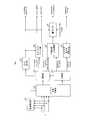
- FIG. 2is a block diagram showing a configuration example of the encoding apparatus 100 according to the present embodiment.
- encoding apparatus 100employs a configuration including a sound source estimation unit 101, a sparse sound field decomposition unit 102, an object encoding unit 103, a space-time Fourier transform unit 104, and a quantizer 105. .
- an acoustic signal yis input to the sound source estimation unit 101 and the sparse sound field decomposition unit 102 from a microphone array (not shown) of the encoding device 100.
- the sound source estimation unit 101analyzes the input acoustic signal y (sound source estimation), and in the sound field (the space to be analyzed) an area where the sound source exists (an area with a high probability that a sound source exists) (lattice Estimate the set of points). For example, the sound source estimation unit 101 may use a sound source estimation method using beam forming (BF) shown in Non-Patent Document 1.
- the sound source estimation unit 101performs sound source estimation at grid points coarser than N lattice points (that is, fewer lattice points) in the space to be analyzed for sparse sound field decomposition, and has a high probability that a sound source exists. Select grid points (and their surroundings).
- the sound source estimation unit 101outputs information indicating the estimated area (set of lattice points) to the sparse sound field decomposition unit 102.
- the sparse sound field decomposition unit 102is an acoustic signal input in an area where a sound source is estimated to be present, which is indicated by information input from the sound source estimation unit 101 in a space to be analyzed for sparse sound field decomposition.
- the sound signalis decomposed into a sound source signal x and an environmental noise signal h.
- the sparse sound field decomposition unit 102outputs a sound source signal component (monopole sources (near field)) to the object encoding unit 103 and outputs an environmental noise signal component (ambience (far field)) to the space-time Fourier transform unit 104. . Further, the sparse sound field decomposition unit 102 outputs lattice point information indicating the position of the sound source signal (source location) to the object encoding unit 103.
- the object encoding unit 103encodes the sound source signal and lattice point information input from the sparse sound field decomposition unit 102, and outputs the encoding result as a set of object data (object signal) and metadata.
- object data and metadataconstitute an object encoded bit stream (object bitstream).
- the object encoding unit 103may use an existing acoustic encoding method for encoding the acoustic signal component x.
- the metadataincludes, for example, lattice point information indicating the position of the lattice point corresponding to the sound source signal.
- the space-time Fourier transform unit 104performs space-time Fourier transform on the environment noise signal input from the sparse sound field decomposition unit 102, and the environment noise signal after the space-time Fourier transform (space-time Fourier coefficient, two-dimensional Fourier coefficient) ) Is output to the quantizer 105.
- the space-time Fourier transform unit 104may use a two-dimensional Fourier transform disclosed in Patent Document 1.
- the quantizer 105quantizes and encodes the spatio-temporal Fourier coefficient input from the spatio-temporal Fourier transform unit 104 and outputs it as an environment noise encoded bit stream (bitstream for ambience).
- the quantizer 105may use the quantization coding method (for example, psycho-acoustic model) disclosed in Patent Document 1.
- the space-time Fourier transform unit 104 and the quantizer 105may be referred to as an environmental noise encoding unit.
- the object encoded bit stream and the environmental noise bit streamare multiplexed and transmitted to the decoding apparatus 200 (not shown), for example.
- FIG. 3is a block diagram showing a configuration of decoding apparatus 200 according to the present embodiment.
- a decoding apparatus 200includes an object decoding unit 201, a wavefront synthesis unit 202, an environmental noise decoding unit (inverse quantizer) 203, a wavefront reconstruction filter (Wavefield reconstruction filter) 204, and an inverse space-time Fourier.
- a configuration including a conversion unit 205, a windowing unit 206, and an addition unit 207is adopted.
- the decoding device 200includes a speaker array including a plurality of speakers (not shown). Also, the decoding apparatus 200 receives the signal from the encoding apparatus 100 shown in FIG. 2, and separates the received signal into an object encoded bit stream (object bitstream) and an environmental noise encoded bitstream (ambience (bitstream) ( Not shown).
- object bitstreamobject encoded bit stream
- ambientambient
- the object decoding unit 201decodes the input object encoded bitstream, separates it into an object signal (sound source signal component) and metadata, and outputs it to the wavefront synthesis unit 202. Note that the object decoding unit 201 may perform the decoding process by the reverse process of the encoding method used in the object encoding unit 103 of the encoding apparatus 100 illustrated in FIG.
- the wavefront synthesis unit 202uses the object signal and metadata input from the object decoding unit 201 and speaker arrangement information (loudspeaker configuration) that is input or set separately to output an output signal from each speaker of the speaker array.
- the obtained output signalis output to the adder 207.
- a method disclosed in Patent Document 3may be used as the output signal generation method in the wavefront synthesis unit 202.
- the environmental noise decoding unit 203decodes the two-dimensional Fourier coefficient included in the environmental noise encoded bitstream, and outputs the decoded environmental noise signal component (ambience, eg, two-dimensional Fourier coefficient) to the wavefront resynthesis filter 204. To do.
- the environmental noise decoding unit 203may perform the decoding process by a process reverse to the encoding process in the quantizer 105 of the encoding apparatus 100 shown in FIG.
- the wavefront re-synthesizing filter 204is collected by the microphone array of the encoding device 100 using the environmental noise signal component input from the environmental noise decoding unit 203 and the speaker arrangement information (loudspeaker configuration) input or set separately.
- the sound signal that has been soundedis converted into a signal to be output from the speaker array of the decoding device 200, and the converted signal is output to the inverse space-time Fourier transform unit 205.
- a method disclosed in Patent Document 3may be used as a method for generating an output signal in the wavefront resynthesis filter 204.
- the inverse space-time Fourier transform unit 205performs an inverse space-time Fourier transform (Inverse space-time Fourier transform) on the signal input from the wavefront resynthesis filter 204, and a time signal to be output from each speaker of the speaker array. (Environmental noise signal)
- the inverse space-time Fourier transform unit 205outputs a time signal to the windowing unit 206. Note that the transformation process in the inverse space-time Fourier transform unit 205 may use, for example, the method disclosed in Patent Document 1.
- the windowing unit 206performs a windowing process (Tapering windowing) on the time signal (environmental noise signal) to be output from each speaker, which is input from the inverse space-time Fourier transform unit 205, and outputs a signal between frames. Connect smoothly.
- the windowing unit 206outputs the signal after the windowing process to the adder 207.
- the adder 207adds the sound source signal input from the wavefront synthesis unit 202 and the environmental noise signal input from the windowing unit 206, and outputs the added signal to each speaker as a final decoded signal.
- FIG. 4is a flowchart showing a processing flow of the encoding apparatus 100 according to the present embodiment.
- the sound source estimation unit 101estimates an area where a sound source exists in the sound field using, for example, a method based on beamforming disclosed in Non-Patent Document 1 (ST101). At this time, the sound source estimation unit 101 has an area (coarse) in which the sound source exists in a space to be analyzed in the sparse decomposition with a coarser granularity than the granularity of the lattice points (positions) that the sound source is assumed to exist at the time of sparse sound field decomposition. area) is estimated (specified).
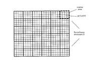
- FIG. 5shows an example of a space S (surveillance enclosure) (that is, a sound field observation area) composed of each lattice point (that is, corresponding to the sound source signal component x) to be analyzed by the sparse decomposition.
- the space Sis represented in two dimensions, but the actual space may be three-dimensional.
- the acoustic signal yis separated into the sound source signal x and the environmental noise signal h in units of each lattice point shown in FIG.
- an area (coarse area) that is a target of sound source estimation by beam forming of the sound source estimation unit 101is represented by an area that is coarser than a sparse decomposition lattice point. That is, the area to be subjected to sound source estimation is represented by a plurality of lattice points for sparse sound field decomposition.
- the sound source estimation unit 101estimates the position where the sound source exists with a coarser granularity than the granularity from which the sparse sound field decomposition unit 102 extracts the sound source signal x.
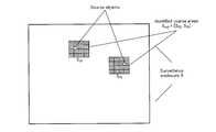
- FIG. 6shows an example of areas (identified coarse areas) that the sound source estimation unit 101 identifies as areas where sound sources exist in the space S shown in FIG.
- the energy of the area S 23 and S 35(coarse area) is higher than the energy of other areas.
- the sound source estimation unit 101identifies S 23 and S 35 as the set S sub of the area where the sound source (source object) exists.
- a sound source signal x corresponding to a plurality of lattice points in the area S sub identified by the sound field estimation unit 101is represented as “x sub ”, and a plurality of matrix D (M ⁇ N) in S sub
- D subA matrix composed of elements corresponding to the relationship between the lattice points and the plurality of microphones of the encoding apparatus 100 is represented as “D sub ”.
- the sparse sound field decomposition unit 102decomposes the acoustic signal y observed by each microphone into a sound source signal xsub and an environmental noise signal h as shown in the following equation (3).
- the encoding apparatus 100(the object encoding unit 103, the space-time Fourier transform unit 104, and the quantization unit 105) encodes the sound source signal xsub and the environmental noise signal h (ST103), and the obtained bit stream (object An encoded bit stream and an environmental noise encoded bit stream are output (ST104). These signals are transmitted to the decoding device 200 side.
- sound source estimation section 101has a grid point indicating a position where a sound source is assumed to exist in sparse sound field decomposition in a space that is subject to sparse sound field decomposition.
- the area where the sound source existsis estimated with a grain size (second grain size) coarser than the grain size (first grain size).
- disassembly part 102is the said with respect to the acoustic signal y observed with a microphone array in the area (coarse
- a sparse sound field decomposition processis performed with the first granularity to decompose the acoustic signal y into a sound source signal x and an environmental noise signal h.
- the encoding apparatus 100preliminarily searches for an area having a high probability that a sound source exists, and limits the analysis target of the sparse sound field decomposition to the searched area. In other words, the encoding apparatus 100 limits the application range of the sparse sound field decomposition to surrounding lattice points where a sound source exists among all lattice points.
- the sparse sound field decompositionis compared with the case where the sparse sound field decomposition process is performed on all the lattice points. The processing amount of processing can be greatly reduced.
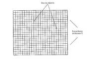
- FIG. 8shows a state where sparse sound field decomposition is performed on all lattice points.
- a matrix operation using all grid points in the space to be analyzedis required as in the method disclosed in Patent Document 3.
- the area to be analyzed for the sparse sound field decomposition of the present embodimentis reduced to S sub . For this reason, since the dimension of the vector of the sound source signal x sub is reduced in the sparse sound field decomposition unit 102, the amount of matrix calculation for the matrix D sub is reduced.
- the sparse decomposition of the sound fieldcan be performed with a low amount of computation.
- the under-determined conditionis relaxed by reducing the number of columns of the matrix D sub , so that the performance of sparse sound field decomposition can be improved.
- FIG. 9is a block diagram showing a configuration of coding apparatus 300 according to the present embodiment.
- the same components as those in the first embodiment (FIG. 2)are denoted by the same reference numerals, and the description thereof is omitted.
- the encoding apparatus 300 illustrated in FIG. 9newly includes a bit distribution unit 301 and a switching unit 302 with respect to the configuration of the first embodiment (FIG. 2).
- the bit allocation unit 301receives information indicating the number of sound sources estimated to exist in the sound field from the sound source estimation unit 101 (that is, the number of areas where the sound source is estimated to exist).
- the bit distribution unit 301Based on the number of sound sources estimated by the sound source estimation unit 101, the bit distribution unit 301 performs a sparse sound field decomposition mode similar to that in Embodiment 1 and the space-time spectrum encoding disclosed in Patent Literature 1. Decide which mode you want to apply. For example, when the estimated number of sound sources is less than or equal to a predetermined number (threshold), the bit distribution unit 301 determines the mode for performing sparse sound field decomposition, and when the estimated number of sound sources exceeds the predetermined number, the sparse sound field The mode is determined to perform space-time spectral coding without performing decomposition.
- a predetermined numberthreshold
- the predetermined numbermay be, for example, the number of sound sources that does not provide sufficient encoding performance by sparse sound field decomposition (that is, the number of sound sources that does not provide sparsity).
- the predetermined numbermay be an upper limit value of the number of objects that can be transmitted at the bit rate when the bit rate of the bit stream is determined.
- the bit distribution unit 301outputs switching information (switching information) indicating the determined mode to the switching unit 302, the object encoding unit 303, and the quantization unit 305.
- the switching informationis transmitted to a decoding device 400 (described later) together with the object encoded bit stream and the environmental noise encoded bit stream (not shown).
- the switching informationis not limited to the determined mode, and may be information indicating the bit allocation between the object encoded bit stream and the environmental noise encoded bit stream.
- the switching informationindicates the number of bits allocated to the object encoded bit stream in the mode in which sparse sound field decomposition is applied, and the number of bits allocated to the object encoded bit stream in the mode in which sparse sound field decomposition is not applied. It may indicate zero.
- the switching informationmay indicate the number of bits of the environmental noise encoded bit stream.
- the switching unit 302switches the output destination of the acoustic signal y according to the encoding mode according to the switching information (mode information or bit distribution information) input from the bit distribution unit 301. Specifically, the switching unit 302 outputs the acoustic signal y to the sparse sound field decomposition unit 102 in the mode in which the same sparse sound field decomposition as in the first embodiment is applied. On the other hand, the switching unit 302 outputs the acoustic signal y to the spatio-temporal Fourier transform unit 304 in the mode for performing space-time spectrum encoding.
- the object encoding unit 303is an embodiment.
- the object codingis performed on the sound source signal in the same manner as in 1.
- the object encoding unit 303does not perform encoding in a mode in which space-time spectrum encoding is performed (for example, when the estimated number of sound sources exceeds a threshold).
- the space-time Fourier transform unit 304receives the environmental noise signal h input from the sparse sound field decomposition unit 102 in the mode for performing sparse sound field decomposition, or from the switching unit 302 in the mode for performing space-time spectrum encoding.
- the input acoustic signal yis subjected to space-time Fourier transform, and a signal (two-dimensional Fourier coefficient) after the space-time Fourier transform is output to the quantizer 305.
- the quantizer 305performs quantization encoding of the two-dimensional Fourier coefficients in the same manner as in the first embodiment. Do. On the other hand, the quantizer 305 quantizes and encodes a two-dimensional Fourier coefficient in the same manner as in Patent Document 1 in the case of a mode in which space-time spectrum encoding is performed.
- FIG. 10is a block diagram showing a configuration of decoding apparatus 400 according to the present embodiment.
- the decoding apparatus 400 shown in FIG. 10newly includes a bit distribution unit 401 and a separation unit 402 in addition to the configuration of the first embodiment (FIG. 3).
- the decoding apparatus 400receives a signal from the encoding apparatus 300 shown in FIG. 9, outputs switching information (switching information) to the bit distribution unit 401, and outputs other bit streams to the separation unit 402.
- the bit allocation unit 401determines bit allocation between the object encoded bit stream and the environmental noise encoded bit stream in the received bit stream, and transmits the determined bit allocation information to the separation unit 402. Output. Specifically, when the encoding apparatus 300 performs sparse sound field decomposition, the bit allocation unit 401 determines the number of bits allocated to each of the object encoded bit stream and the environmental noise encoded bit stream. On the other hand, when space-time spectrum encoding is performed by the encoding apparatus 300, the bit allocation unit 401 allocates bits to the environmental noise encoded bitstream without allocating bits to the object encoded bitstream.
- the separation unit 402separates the input bit stream into various parameter bit streams according to the bit distribution information input from the bit distribution unit 401. Specifically, when the sparse sound field decomposition is performed in the encoding device 300, the separation unit 402 converts the bit stream into the object encoded bit stream and the environmental noise encoded bit stream as in the first embodiment. And output to the object decoding unit 201 and the environmental noise decoding unit 203, respectively. On the other hand, when the encoding apparatus 300 performs space-time spectrum encoding, the separation unit 402 outputs the input bit stream to the environmental noise decoding unit 203 and outputs nothing to the object decoding unit 201. .
- encoding apparatus 300determines whether to apply sparse sound field decomposition described in Embodiment 1 according to the number of sound sources estimated by sound source estimation section 101. To do.
- the sparse sound field decompositionassumes the sparseness of the sound source in the sound field
- a situation where the number of sound sources is largemay not be optimal as an analysis model for the sparse sound field decomposition. That is, when the number of sound sources increases, the sparseness of the sound sources in the sound field decreases, and when the sparse sound field decomposition is applied, there is a possibility that the expression capability or decomposition performance of the analysis model is deteriorated.
- Patent Document 1Spatio-temporal spectral coding as shown is performed. Note that the encoding model when the number of sound fields is large is not limited to the spatio-temporal spectrum encoding as shown in Patent Document 1.
- the encoding modelcan be flexibly switched according to the number of sound sources, so that highly efficient encoding can be realized.
- the estimated position of the sound sourcemay be input from the sound source estimation unit 101 to the bit distribution unit 301.
- the bit distribution unit 301may set the bit distribution (or the threshold value of the number of sound sources) between the sound source signal component x and the environmental noise signal h based on the position information of the sound source.
- the bit distribution unit 301may increase the bit distribution of the sound source signal component x as the position of the sound source is closer to the front position with respect to the microphone array.
- the decoding apparatus according to the present embodimenthas the same basic configuration as that of decoding apparatus 400 according to Embodiment 2, and will be described with reference to FIG.
- FIG. 11is a block diagram showing a configuration of coding apparatus 500 according to the present embodiment.
- the same components as those in the second embodiment (FIG. 9)are denoted by the same reference numerals, and the description thereof is omitted.
- the coding apparatus 500 shown in FIG. 11newly includes a selection unit 501 with respect to the configuration of the second embodiment (FIG. 9).
- the selection unit 501selects some main sound sources (for example, a predetermined number of sound sources in descending order of energy) from the sound source signal x (sparse sound source) input from the sparse sound field decomposition unit 102. Then, the selection unit 501 outputs the selected sound source signal as an object signal (monopole sources) to the object encoding unit 303, and the remaining sound source signal that has not been selected as an ambient noise signal (ambience). Output to.
- some main sound sourcesfor example, a predetermined number of sound sources in descending order of energy
- the selection unit 501reclassifies a part of the sound source signal x generated (extracted) by the sparse sound field decomposition unit 102 as the environmental noise signal h.
- the space-time Fourier transform unit 502receives the environmental noise signal h input from the sparse sound field decomposition unit 102 and the environmental noise signal h input from the selection unit 501 (re-classification). Space-time spectrum encoding is performed on the generated sound source signal).
- the encoding apparatus 500selects a main component from the sound source signal extracted by the sparse sound field decomposition unit 102 and performs object encoding to use the object encoding. Even when the number of possible bits is limited, it is possible to ensure bit allocation for more important objects. Thereby, the overall encoding performance by sparse sound field decomposition can be improved.
- the decoding apparatus according to Method 1 of the present embodimenthas the same basic configuration as that of decoding apparatus 400 according to Embodiment 2, and will be described with reference to FIG.
- FIG. 12is a block diagram showing a configuration of coding apparatus 600 according to method 1 of the present embodiment.
- the same components as those in the second embodiment (FIG. 9) or the third embodiment (FIG. 11)are denoted by the same reference numerals, and the description thereof is omitted.
- the encoding apparatus 600 shown in FIG. 12newly includes a selection unit 601 and a bit distribution update unit 602 with respect to the configuration of the second embodiment (FIG. 9).
- the selection unit 601is a predetermined main sound source (for example, predetermined in descending order of energy) of the sound source signal x input from the sparse sound field decomposition unit 102. Number of sound sources). At this time, the selection unit 601 calculates the energy of the environmental noise signal h input from the sparse sound field decomposition unit 102. If the energy of the environmental noise signal is equal to or less than a predetermined threshold, the energy of the environmental noise signal is predetermined. More sound source signals x than when exceeding the threshold value are output to the object encoding unit 303 as the main sound source. The selection unit 601 outputs information indicating increase / decrease of bit distribution to the bit distribution update unit 602 according to the selection result of the sound source signal x.
- the selection unit 601outputs information indicating increase / decrease of bit distribution to the bit distribution update unit 602 according to the selection result of the sound source signal x.
- the bit allocation update unit 602Based on the information input from the selection unit 601, the bit allocation update unit 602 converts the number of bits allocated to the excitation signal encoded by the object encoding unit 303 and the environmental noise signal quantized by the quantizer 305. Determine the allocation with the number of bits to be allocated. That is, the bit distribution update unit 602 updates the switching information (bit distribution information) of the bit distribution unit 301.
- the bit allocation updating unit 602outputs switching information indicating the updated bit allocation to the object encoding unit 303 and the quantization unit 305. Also, the switching information is multiplexed and transmitted to the decoding apparatus 400 (FIG. 10) together with the object encoded bit stream and the environmental noise encoded bit stream (not shown).
- the object encoding unit 303 and the quantizer 305respectively encode or quantize the sound source signal x or the environmental noise signal h in accordance with the bit allocation indicated by the switching information input from the bit allocation update unit 602.
- the environmental noise signal with low energy and reduced bit allocationmay not be encoded at all, and may be artificially generated as environmental noise of a predetermined threshold level on the decoding side.
- energy informationmay be encoded and transmitted with respect to an environmental noise signal with low energy. In this case, bit allocation for the environmental noise signal is required, but if only energy information is used, less bit allocation is required compared to the case where the environmental noise signal h is included.
- Method 2In Method 2, an example of an encoding device and a decoding device having a configuration for encoding and transmitting energy information of an environmental noise signal as described above will be described.
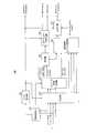
- FIG. 13is a block diagram showing a configuration of coding apparatus 700 according to method 2 of the present embodiment.
- the same components as those in the first embodiment (FIG. 2)are denoted by the same reference numerals, and the description thereof is omitted.
- the coding apparatus 700 shown in FIG. 13includes a switching unit 701, a selection unit 702, a bit distribution unit 703, and an energy quantization coding unit 704, compared to the configuration of the first embodiment (FIG. 2). Newly prepared.
- the excitation signal x obtained by the sparse sound field decomposition unit 102is output to the selection unit 702, and the environmental noise signal h is output to the switching unit 701.
- the switching unit 701calculates the energy of the environmental noise signal input from the sparse sound field decomposition unit 102, and determines whether the calculated energy of the environmental noise signal exceeds a predetermined threshold. When the energy of the environmental noise signal is equal to or lower than a predetermined threshold, the switching unit 701 outputs information (ambience energy) indicating the energy of the environmental noise signal to the energy quantization encoding unit 704. On the other hand, the switching unit 701 outputs the environmental noise signal to the space-time Fourier transform unit 104 when the energy of the environmental noise signal exceeds a predetermined threshold. In addition, the switching unit 701 outputs information (determination result) indicating whether or not the energy of the environmental noise signal has exceeded a predetermined threshold value to the selection unit 702.
- the selection unit 702selects a sound source signal (sparse sound source) input from the sparse sound source separation unit 102 based on information input from the switching unit 701 (information indicating whether or not the energy of the environmental noise signal exceeds a predetermined threshold). ), The number of sound sources to be object-coded (the number of sound sources to be selected) is determined. For example, as in the selection unit 601 of the encoding apparatus 600 according to the method 1, the selection unit 702 selects the number of sound sources to be selected as the object encoding target when the energy of the environmental noise signal is equal to or lower than a predetermined threshold. It is set to be larger than the number of sound sources selected as the object encoding target when the energy exceeds a predetermined threshold.
- the selection unit 702selects the determined number of sound source components and outputs them to the object encoding unit 103. At this time, the selection unit 702 may select, for example, in order from main sound sources (for example, a predetermined number of sound sources in descending order of energy). Further, the selection unit 702 outputs the remaining sound source signals (monopole sources (non-dominant)) not selected to the space-time Fourier transform unit 104.
- main sound sourcesfor example, a predetermined number of sound sources in descending order of energy.
- the selection unit 702outputs the remaining sound source signals (monopole sources (non-dominant)) not selected to the space-time Fourier transform unit 104.
- the selection unit 702outputs the determined number of sound sources and information input from the switching unit 701 to the bit distribution unit 703.
- the bit distribution unit 703Based on the information input from the selection unit 702, the bit distribution unit 703 allocates the number of bits allocated to the sound source signal encoded by the object encoding unit 103 and the environmental noise signal quantized by the quantizer 105. Set the distribution with the number of bits.
- the bit allocation unit 703outputs switching information indicating the bit allocation to the object encoding unit 103 and the quantization unit 105. The switching information is multiplexed and transmitted (not shown) to the decoding apparatus 800 (FIG. 14) described later together with the object coded bit stream and the environmental noise coded bit stream.
- the energy quantization encoding unit 704quantizes and encodes the environmental noise energy information input from the switching unit 701 and outputs encoded information (ambience energy).
- the encoded informationis multiplexed and transmitted as an environmental noise energy encoded bit stream to a decoding apparatus 800 (FIG. 14) described later together with the object encoded bit stream, the environmental noise encoded bit stream, and the switching information (not shown). )
- the encoding apparatus 700may additionally encode the sound source signal within the range allowed by the bit rate without encoding the environmental noise signal.
- the encoding apparatus according to method 2performs sparse sound field decomposition according to the number of sound sources estimated by the sound source estimation unit 101 as described in the second embodiment (FIG. 9). You may provide the structure which switches another encoding model. Or the encoding apparatus which concerns on the method 2 does not need to include the structure of the sound source estimation part 101 shown in FIG.
- the encoding apparatus 700may calculate the average value of the energy of all channels as the energy of the environmental noise signal described above, or may use another method. Other methods include, for example, a method that uses channel-specific information as the energy of the environmental noise signal, or a method that divides all channels into subgroups and obtains average energy in each subgroup. At this time, the encoding apparatus 700 may determine whether or not the energy of the environmental noise signal exceeds the threshold using the average value of all the channels. You may perform using the maximum value among the energy of the environmental noise signal calculated
- the encoding apparatus 700may apply scalar quantization as the energy quantization encoding when the average energy of all the channels is used, and scalar encoding when encoding a plurality of energies.
- vector quantizationmay be applied.
- predictive quantization using inter-frame correlationis also effective.
- FIG. 14is a block diagram showing a configuration of decoding apparatus 800 according to method 2 of the present embodiment.
- decoding apparatus 800 shown in FIG. 14newly includes pseudo-environment noise decoding unit 801 with respect to the configuration of the second embodiment (FIG. 10).
- the pseudo environmental noise decoding unit 801decodes the pseudo environmental noise signal using the environmental noise energy encoded bit stream input from the separation unit 402 and the pseudo environmental noise source separately held by the decoding apparatus 800, and re-wavefront Output to the synthesis filter 204.
- the pseudo-environmental noise decoding unit 801incorporates a process that considers conversion from the microphone array of the encoding device 700 to the speaker array of the decoding device 800, the output to the wavefront resynthesis filter 204 is skipped, It is possible to perform a decoding process such as outputting to the inverse space-time Fourier transform unit 205.
- encoding apparatuses 600 and 700are as many as possible for encoding sound source signal components rather than encoding environmental noise signals when the energy of the environmental noise signals is small. Re-allocate the bits to perform object encoding. Thereby, the encoding performance in the encoding apparatuses 600 and 700 can be improved.
- the encoding information of the energy of the environmental noise signal extracted by the sparse sound field decomposition unit 102 of the encoding device 700is transmitted to the decoding device 800.
- the decoding device 800generates a pseudo environmental noise signal based on the energy of the environmental noise signal.
- Each functional block used in the description of the above embodimentis partially or entirely realized as an LSI that is an integrated circuit, and each process described in the above embodiment may be partially or entirely performed. It may be controlled by one LSI or a combination of LSIs.
- the LSImay be composed of individual chips, or may be composed of one chip so as to include a part or all of the functional blocks.
- the LSImay include data input and output.
- An LSImay be referred to as an IC, a system LSI, a super LSI, or an ultra LSI depending on the degree of integration.
- the method of circuit integrationis not limited to LSI, and may be realized by a dedicated circuit, a general-purpose processor, or a dedicated processor.
- an FPGAField Programmable Gate Array
- a reconfigurable processorthat can reconfigure the connection and setting of circuit cells inside the LSI may be used.
- the present disclosuremay be implemented as digital processing or analog processing.
- integrated circuit technologycomes out to replace LSI's as a result of the advancement of semiconductor technology or a derivative other technology, it is naturally also possible to carry out function block integration using this technology. Biotechnology can be applied.
- a sound sourceexists in a space to be subjected to sparse sound field decomposition with a second granularity coarser than the first granularity at a position where a sound source is assumed to exist in the sparse sound field decomposition.
- a decomposition circuitthat performs sparse sound field decomposition processing and decomposes the acoustic signal into a sound source signal and an environmental noise signal.
- the decomposition circuitperforms the sparse sound field decomposition processing when the number of areas estimated by the estimation circuit to be present of the sound source is equal to or less than a first threshold, and the number of the areas When the value exceeds the first threshold, the sparse sound field decomposition process is not performed.
- the first encoding circuitwhen the number of areas is equal to or less than the first threshold, the first encoding circuit that encodes the excitation signal, and the number of areas is equal to or less than the first threshold. And a second encoding circuit that encodes the environmental noise signal and encodes the acoustic signal when the number of the areas exceeds the first threshold.
- a part of the sound source signal generated by the decomposition circuitis output as an object signal, and the remainder of the sound source signal generated by the decomposition circuit is output as the environmental noise signal.
- a selection circuitis provided.
- the number of the partial sound source signals selected when the energy of the environmental noise signal generated by the decomposition circuit is equal to or lower than a second thresholdis the energy of the environmental noise signal.
- the numberis larger than the number of the partial sound source signals selected when the second threshold value is exceeded.
- the encoding apparatusfurther includes a quantization encoding circuit that performs quantization encoding of information indicating the energy when the energy is equal to or less than the second threshold value.
- a sound sourceexists in a space to be subjected to sparse sound field decomposition with a second granularity coarser than the first granularity at a position where a sound source is assumed to exist in the sparse sound field decomposition.
- the sparse sound field with the first granularityis estimated with respect to the acoustic signal observed by the microphone array in the area of the second granularity in which the sound source is estimated to exist in the space.
- a decomposition processis performed to decompose the acoustic signal into a sound source signal and an environmental noise signal.
- One embodiment of the present disclosureis useful for a voice communication system.
Landscapes
- Engineering & Computer Science (AREA)
- Physics & Mathematics (AREA)
- Health & Medical Sciences (AREA)
- Acoustics & Sound (AREA)
- Signal Processing (AREA)
- Computational Linguistics (AREA)
- Audiology, Speech & Language Pathology (AREA)
- Human Computer Interaction (AREA)
- Multimedia (AREA)
- Otolaryngology (AREA)
- Spectroscopy & Molecular Physics (AREA)
- Mathematical Physics (AREA)
- Quality & Reliability (AREA)
- General Health & Medical Sciences (AREA)
- Circuit For Audible Band Transducer (AREA)
- Compression, Expansion, Code Conversion, And Decoders (AREA)
Abstract
Description
Translated fromJapanese本開示は、符号化装置及び符号化方法に関する。The present disclosure relates to an encoding device and an encoding method.
波面合成符号化技術として、波面合成符号化を時空間周波数領域で行う方法が提案されている(例えば、特許文献1を参照)。As a wavefront synthesis coding technique, a method of performing wavefront synthesis coding in the spatio-temporal frequency domain has been proposed (see, for example, Patent Document 1).
また、立体音響に対して主要音源成分と環境音成分とに分離符号化する高能率符号化のモデル(例えば、特許文献2を参照)を波面合成に適用し、スパース音場分解(sparse sound field decomposition)を用いて、マイクロホンアレイで観測される音響信号を、少数の点音源(monopole source)と点音源以外の残差成分とに分離して波面合成を行う方法が提案されている(例えば、特許文献3を参照)。In addition, a high-efficiency coding model (see, for example, Patent Document 2) that separates and encodes main sound source components and environmental sound components for stereophonic sound is applied to wavefront synthesis, and sparse sound field decomposition decomposition), a method of separating the acoustic signal observed by the microphone array into a small number of point sources (monopole source) and residual components other than point sources and performing wavefront synthesis (for example, (See Patent Document 3).
しかしながら、特許文献1では、音場情報を全て符号化するため、演算量が膨大となる。また、特許文献3では、スパース分解を用いて点音源を抽出する際に、分析対象となる空間内の点音源が存在し得る全ての位置(格子点(grig point))を用いた行列演算が必要となり、演算量が膨大となる。However, in Patent Document 1, since all the sound field information is encoded, the amount of calculation becomes enormous. Further, in Patent Document 3, when a point sound source is extracted using sparse decomposition, matrix calculation using all positions (grid points) where point sound sources in the space to be analyzed can exist is performed. This is necessary and the calculation amount becomes enormous.
本開示の一態様は、低演算量で音場のスパース分解を行うことができる符号化装置及び符号化方法の提供に資する。One aspect of the present disclosure contributes to the provision of an encoding device and an encoding method capable of performing sparse decomposition of a sound field with a low amount of computation.
本開示の一態様に係る符号化装置は、スパース音場分解の対象となる空間において、前記スパース音場分解において音源が存在すると仮定する位置の第1の粒度よりも粗い第2の粒度で、音源が存在するエリアを推定する推定回路と、前記空間のうちの前記音源が存在すると推定された前記第2の粒度のエリア内において、マイクロホンアレイで観測される音響信号に対して、前記第1の粒度で前記スパース音場分解処理を行って、前記音響信号を音源信号と環境雑音信号とに分解する分解回路と、を具備する構成を採る。The encoding device according to an aspect of the present disclosure has a second granularity coarser than the first granularity at a position where a sound source is assumed to exist in the sparse sound field decomposition in a space to be subjected to sparse sound field decomposition. An estimation circuit for estimating an area where a sound source exists, and an acoustic signal observed by a microphone array in the second granularity area of the space where the sound source is estimated to exist. And a decomposition circuit that decomposes the acoustic signal into a sound source signal and an environmental noise signal.
本開示の一態様に係る符号化方法は、スパース音場分解の対象となる空間において、前記スパース音場分解において音源が存在すると仮定する位置の第1の粒度よりも粗い第2の粒度で、音源が存在するエリアを推定し、前記空間のうちの前記音源が存在すると推定された前記第2の粒度のエリア内において、マイクロホンアレイで観測される音響信号に対して、前記第1の粒度で前記スパース音場分解処理を行って、前記音響信号を音源信号と環境雑音信号とに分解する。In the encoding method according to an aspect of the present disclosure, the second granularity coarser than the first granularity of the position where it is assumed that a sound source exists in the sparse acoustic field decomposition in the space to be subjected to the sparse acoustic field decomposition, An area where a sound source exists is estimated, and an acoustic signal observed by a microphone array in the area of the second granularity in which the sound source is estimated to be present in the space, with the first granularity. The sparse sound field decomposition process is performed to decompose the acoustic signal into a sound source signal and an environmental noise signal.
なお、これらの包括的または具体的な態様は、システム、方法、集積回路、コンピュータプログラム、または、記録媒体で実現されてもよく、システム、装置、方法、集積回路、コンピュータプログラムおよび記録媒体の任意な組み合わせで実現されてもよい。Note that these comprehensive or specific aspects may be realized by a system, method, integrated circuit, computer program, or recording medium. Any of the system, apparatus, method, integrated circuit, computer program, and recording medium may be used. It may be realized by various combinations.
本開示の一態様によれば、低演算量で音場のスパース分解を行うことができる。According to one aspect of the present disclosure, sparse decomposition of a sound field can be performed with a low amount of computation.
本開示の一態様における更なる利点および効果は、明細書および図面から明らかにされる。かかる利点および/または効果は、いくつかの実施形態並びに明細書および図面に記載された特徴によってそれぞれ提供されるが、1つまたはそれ以上の同一の特徴を得るために必ずしも全てが提供される必要はない。Further advantages and effects of one aspect of the present disclosure will become apparent from the specification and drawings. Such advantages and / or effects are provided by some embodiments and features described in the description and drawings, respectively, but all need to be provided in order to obtain one or more identical features. There is no.
以下、本開示の実施の形態について図面を参照して詳細に説明する。Hereinafter, embodiments of the present disclosure will be described in detail with reference to the drawings.
なお、以下では、符号化装置において、スパース分解を用いて点音源を抽出する際の分析対象となる空間(音場)内の点音源が存在する可能性のある位置を表す格子点数を「N」個とする。In the following, in the encoding apparatus, the number of grid points representing the position where a point sound source in a space (sound field) to be analyzed when a point sound source is extracted using sparse decomposition may exist is “N”. ”.
また、符号化装置は、「M」個のマイクロホンを含むマイクロホンアレイを備える(図示せず)。Also, the encoding device includes a microphone array including “M” microphones (not shown).
また、各マイクロホンで観測される音響信号を「y」(∈CM)と表す。また、音響信号yに含まれる、各格子点における音源信号成分(モノポール音源成分の分布)を「x」(∈CN)と表し、音源信号成分以外の残りの成分である環境雑音信号(残差成分)を「h」(∈CM)と表す。In addition, an acoustic signal observed by each microphone is represented as “y” (∈CM ). Further, the sound source signal component (distribution of monopole sound source component) at each lattice point included in the acoustic signal y is represented by “x” (∈CN ), and the environmental noise signal (the remaining component other than the sound source signal component) (Residual component) is represented as “h” (∈CM ).
すなわち、次式(1)に示すように、音響信号yは、音源信号xと環境雑音信号hとで表される。すなわち、符号化装置は、スパース音場分解において、マイクロホンアレイで観測される音響信号yを、音源信号xと環境雑音信号hとに分解する。
なお、D(∈CM×N)は、各マイクロホンアレイと各格子点との間の伝達関数(例えば、グリーン関数)を要素とするM×Nの行列(dictionary matrix)である。行列Dは、例えば、符号化装置において、各マイクロホンと各格子点との位置関係に基づいて、少なくともスパース音場分解の前に求められていればよい。Note that D (εCM × N ) is an M × N dictionary (dictionary matrix) having a transfer function (for example, a Green function) between each microphone array and each lattice point as an element. For example, the matrix D may be obtained at least before the sparse sound field decomposition based on the positional relationship between each microphone and each lattice point in the encoding device.
ここで、スパース音場分解の対象となる空間において、ほとんどの格子点における音源信号成分xがゼロとなり、少数の格子点の音源信号成分xが非ゼロとなる特性(スパース性。sparsity constraint)を仮定する。例えば、スパース音場分解では、スパース性を利用して、次式(2)で示される基準を満たす音源信号成分xを得る。
関数Jp,q(x)は、音源信号成分xのスパース性を生じさせるためのペナルティ関数を示し、λは、ペナルティと近似誤差とのバランスを取るパラメータである。The function Jp, q (x) represents a penalty function for generating the sparsity of the sound source signal component x, and λ is a parameter that balances the penalty and the approximation error.
なお、本開示におけるスパース音場分解の具体的な処理については、例えば、特許文献3に示された方法を用いて行われればよい。ただし、本開示において、スパース音場分解の方法は、特許文献3に示された方法に限定されず、他の方法でもよい。In addition, what is necessary is just to perform using the method shown by patent document 3, for example about the specific process of sparse sound field decomposition | disassembly in this indication. However, in the present disclosure, the sparse sound field decomposition method is not limited to the method disclosed in Patent Document 3, and other methods may be used.
ここで、スパース音場分解アルゴリズム(例えば、M-FOCUSS/G-FOCUSS又は最小ノルム解に基づく分解など)では、分析対象となる空間内の全ての格子点を用いた行列演算(逆行列など複素行列演算)が必要となるため、点音源を抽出する場合には演算量が膨大になってしまう。特に、格子点の個数Nが多くなるほど、式(1)に示す音源信号成分xのベクトルの次元が大きくなり、演算量がより大きくなってしまう。Here, in the sparse sound field decomposition algorithm (for example, decomposition based on M-FOCUSS / G-FOCUSS or the minimum norm solution), matrix operation using all grid points in the space to be analyzed (complex such as inverse matrix) Matrix calculation) is required, and the amount of calculation becomes enormous when extracting point sound sources. In particular, as the number N of grid points increases, the dimension of the vector of the sound source signal component x shown in Equation (1) increases and the amount of computation increases.
そこで、本開示の各実施の形態では、スパース音場分解の低演算量化を図る方法について説明する。Therefore, in each embodiment of the present disclosure, a method for reducing the amount of calculation of sparse sound field decomposition will be described.
(実施の形態1)
[通信システムの概要]
本実施の形態に係る通信システムは、符号化装置(encoder)100及び復号装置(decoder)200を備える。(Embodiment 1)
[Outline of communication system]
The communication system according to the present embodiment includes an encoding device (encoder) 100 and a decoding device (decoder) 200.
図1は、本開示の各実施の形態に係る符号化装置100の一部の構成を示すブロック図である。図1に示す符号化装置100において、音源推定部101は、スパース音場分解の対象となる空間において、スパース音場分解において音源が存在すると仮定する位置の第1の粒度よりも粗い第2の粒度で、音源が存在するエリアを推定し、スパース音場分解部102は、空間のうちの音源が存在すると推定された第2の粒度のエリア内において、マイクロホンアレイで観測される音響信号に対して、第1の粒度でスパース音場分解処理を行って、音響信号を音源信号と環境雑音信号とに分解する。FIG. 1 is a block diagram illustrating a configuration of a part of an
[符号化装置の構成]
図2は、本実施の形態に係る符号化装置100の構成例を示すブロック図である。図2において、符号化装置100は、音源推定部101と、スパース音場分解部102と、オブジェクト符号化部103と、空間時間フーリエ変換部104と、量子化器105と、を含む構成を採る。[Configuration of Encoding Device]
FIG. 2 is a block diagram showing a configuration example of the
図2において、符号化装置100のマイクロホンアレイ(図示せず)から音響信号yが音源推定部101及びスパース音場分解部102に入力される。2, an acoustic signal y is input to the sound
音源推定部101は、入力される音響信号yを分析(音源推定)して、音場(分析対象となる空間)の中から音源の存在するエリア(音源が存在する確率の高いエリア)(格子点のセット)を推定する。例えば、音源推定部101は、非特許文献1に示されたビームフォーミング(BF)を用いた音源推定方法を用いてもよい。また、音源推定部101は、スパース音場分解の分析対象となる空間におけるN個の格子点よりも粗い格子点(つまり、少ない格子点)での音源推定を行い、音源の存在する確率の高い格子点(及びその周囲)を選択する。音源推定部101は、推定したエリア(格子点のセット)を示す情報をスパース音場分解部102に出力する。The sound
スパース音場分解部102は、スパース音場分解の分析対象となる空間のうち、音源推定部101から入力される情報に示される、音源が存在すると推定されたエリア内において、入力される音響信号に対してスパース音場分解を行って、音響信号を音源信号xと、環境雑音信号hとに分解する。スパース音場分解部102は、音源信号成分(monopole sources(near field))をオブジェクト符号化部103に出力し、環境雑音信号成分(ambience(far field))を空間時間フーリエ変換部104に出力する。また、スパース音場分解部102は、音源信号の位置(source location)を示す格子点情報をオブジェクト符号化部103に出力する。The sparse sound
オブジェクト符号化部103は、スパース音場分解部102から入力される音源信号及び格子点情報を符号化し、符号化結果をオブジェクトデータ(object signal)とメタデータのセットとして出力する。例えば、オブジェクトデータ及びメタデータは、オブジェクト符号化ビットストリーム(object bitstream)を構成する。なお、オブジェクト符号化部103において、音響信号成分xの符号化には既存の音響符号化方法を用いればよい。また、メタデータには、例えば、音源信号に対応する格子点の位置を表す格子点情報等が含まれる。The
空間時間フーリエ変換部104は、スパース音場分解部102から入力される環境雑音信号に対して空間時間フーリエ変換を行い、空間時間フーリエ変換後の環境雑音信号(空間時間フーリエ係数、二次元フーリエ係数)を量子化器105に出力する。例えば、空間時間フーリエ変換部104は、特許文献1に示された二次元フーリエ変換を用いてもよい。The space-time
量子化器105は、空間時間フーリエ変換部104から入力される空間時間フーリエ係数を量子化及び符号化して、環境雑音符号化ビットストリーム(bitstream for ambience)として出力する。例えば、量子化器105において、特許文献1に示された量子化符号化方法(例えば、心理音響モデル(psycho-acoustic model))を用いてもよい。The
なお、空間時間フーリエ変換部104及び量子化器105は、環境雑音符号化部と呼ばれてもよい。The space-time
オブジェクト符号化ビットストリーム及び環境雑音ビットストリームは、例えば、多重されて復号装置200へ送信される(図示せず)。The object encoded bit stream and the environmental noise bit stream are multiplexed and transmitted to the decoding apparatus 200 (not shown), for example.
[復号装置の構成]
図3は、本実施の形態に係る復号装置200の構成を示すブロック図である。図3において、復号装置200は、オブジェクト復号部201と、波面合成部202と、環境雑音復号部(逆量子化器)203と、波面再合成フィルタ(Wavefield reconstruction filter)204と、逆空間時間フーリエ変換部205と、窓かけ部206と、加算部207と、を含む構成を採る。[Configuration of Decoding Device]
FIG. 3 is a block diagram showing a configuration of
図3において、復号装置200は、複数のスピーカから構成されるスピーカアレイを備える(図示せず)。また、復号装置200は、図2に示す符号化装置100からの信号を受信し、受信信号をオブジェクト符号化ビットストリーム(object bitstream)と環境雑音符号化ビットストリーム(ambience bitstream)とに分離する(図示せず)。3, the
オブジェクト復号部201は、入力されるオブジェクト符号化ビットストリームを復号して、オブジェクト信号(音源信号成分)とメタデータとに分離し、波面合成部202に出力する。なお、オブジェクト復号部201は、図2に示す符号化装置100のオブジェクト符号化部103で用いた符号化方法の逆の処理により復号処理を行えばよい。The
波面合成部202は、オブジェクト復号部201から入力されるオブジェクト信号、メタデータ、及び、別途入力又は設定されているスピーカ配置情報(loudspeaker configuration)を用いて、スピーカアレイの各スピーカからの出力信号を求め、求めた出力信号を加算器207に出力する。なお、波面合成部202における出力信号の生成方法は、例えば、特許文献3に示されている方法を用いてもよい。The
環境雑音復号部203は、環境雑音符号化ビットストリームに含まれる二次元フーリエ係数を復号して、復号された環境雑音信号成分(ambience。例えば、二次元フーリエ係数)を波面再合成フィルタ204に出力する。なお、環境雑音復号部203は、図2に示す符号化装置100の量子化器105における符号化処理と逆の処理により復号処理を行えばよい。The environmental
波面再合成フィルタ204は、環境雑音復号部203から入力される環境雑音信号成分、及び、別途入力又は設定されているスピーカ配置情報(loudspeaker configuration)を用いて、符号化装置100のマイクロホンアレイで集音された音響信号を復号装置200のスピーカアレイから出力するべき信号に変換し、変換された信号を逆空間時間フーリエ変換部205に出力する。なお、波面再合成フィルタ204における出力信号の生成方法は、例えば、特許文献3に示されている方法を用いてもよい。The
逆空間時間フーリエ変換部205は、波面再合成フィルタ204から入力される信号に対して逆空間時間フーリエ変換(Inverse space-time Fourier transform)を行い、スピーカアレイの各スピーカから出力されるべき時間信号(環境雑音信号)に変換する。逆空間時間フーリエ変換部205は、時間信号を窓かけ部206に出力する。なお、逆空間時間フーリエ変換部205における変換処理は、例えば、特許文献1に示されている方法を用いてもよい。The inverse space-time
窓かけ部206は、逆空間時間フーリエ変換部205から入力される、各スピーカから出力されるべき時間信号(環境雑音信号)に対して窓かけ処理(Tapering windowing)を施して、フレーム間の信号をスムーズに接続する。窓かけ部206は、窓かけ処理後の信号を加算器207に出力する。The
加算器207は、波面合成部202から入力される音源信号と、窓かけ部206から入力される環境雑音信号とを加算し、加算信号を最終的な復号信号として各スピーカに出力する。The
[符号化装置100の動作]
以上の構成を有する符号化装置100における動作について詳細に説明する。[Operation of Encoding Device 100]
The operation of the
図4は、本実施の形態に係る符号化装置100の処理の流れを示すフロー図である。FIG. 4 is a flowchart showing a processing flow of the
まず、符号化装置100において、音源推定部101は、例えば、非特許文献1に示されたビームフォーミングに基づく方法を用いて、音場の中の音源が存在するエリアを推定する(ST101)。この際、音源推定部101は、スパース分解の分析対象となる空間において、スパース音場分解時に音源が存在すると仮定する格子点(位置)の粒度よりも粗い粒度で、音源が存在するエリア(coarse area)を推定(特定)する。First, in the
図5は、スパース分解の分析対象となる各格子点(つまり、音源信号成分xに対応)からなる空間S(surveillance enclosure)(つまり、音場の観測エリア)の一例を示す。なお、図5では空間Sを二次元で表すが実際の空間は三次元でもよい。FIG. 5 shows an example of a space S (surveillance enclosure) (that is, a sound field observation area) composed of each lattice point (that is, corresponding to the sound source signal component x) to be analyzed by the sparse decomposition. In FIG. 5, the space S is represented in two dimensions, but the actual space may be three-dimensional.
スパース音場分解は、図5に示す各格子点を単位として音響信号yを音源信号xと環境雑音信号hとに分離する。これに対して、図5に示すように、音源推定部101のビームフォーミングによる音源推定の対象となるエリア(coarse area)は、スパース分解の格子点よりも粗いエリアで表される。つまり、音源推定の対象となるエリアは、スパース音場分解の複数の格子点によって表される。換言すると、音源推定部101は、スパース音場分解部102が音源信号xを抽出する粒度よりも粗い粒度で音源の存在する位置を推定する。In the sparse sound field decomposition, the acoustic signal y is separated into the sound source signal x and the environmental noise signal h in units of each lattice point shown in FIG. On the other hand, as shown in FIG. 5, an area (coarse area) that is a target of sound source estimation by beam forming of the sound
図6は、音源推定部101が図5に示す空間Sにおいて音源が存在するエリアとして特定したエリア(identified coarse areas)の一例を示す。図6では、例えば、S23及びS35のエリア(coarse area)のエネルギが他のエリアのエネルギよりも高くなっているとする。この場合、音源推定部101は、音源(source object)が存在するエリアのセットSsubとして、S23及びS35を特定する。FIG. 6 shows an example of areas (identified coarse areas) that the sound
次に、スパース音場分解部102は、音源推定部101で音源が存在すると推定されたエリア内の格子点についてスパース音場分解を行う(ST102)。例えば、音源推定部101において図6に示すエリア(Ssub=[S23,S35])が特定された場合、スパース音場分解部102は、図7に示すように、特定されたエリア(Ssub=[S23,S35])内におけるスパース音場分解の格子点についてスパース音場分解を行う。Next, sparse sound
例えば、音場推定部101で特定されたエリアSsub内の複数の格子点に対応する音源信号xを「xsub」と表し、行列D(M×N)のうち、Ssub内の複数の格子点と符号化装置100の複数のマイクロホンとの関係に対応する要素からなる行列を「Dsub」と表す。
この場合、スパース音場分解部102は、次式(3)のように、各マイクロホンで観測された音響信号yを、音源信号xsubと環境雑音信号hとに分解する。
In this case, the sparse sound
そして、符号化装置100(オブジェクト符号化部103、空間時間フーリエ変換部104、量子化部105)は、音源信号xsub及び環境雑音信号hを符号化し(ST103)、得られたビットストリーム(オブジェクト符号化ビットストリーム、環境雑音符号化ビットストリーム)を出力する(ST104)。これらの信号は復号装置200側へ送信される。Then, the encoding apparatus 100 (the
このように、本実施の形態では、符号化装置100において、音源推定部101は、スパース音場分解の対象となる空間において、スパース音場分解において音源が存在すると仮定する位置を示す格子点の粒度(第1の粒度)よりも粗い粒度(第2の粒度)で、音源が存在するエリアを推定する。そして、スパース音場分解部102は、空間のうちの音源が存在すると推定された、上記第2の粒度のエリア(coarse area)内において、マイクロホンアレイで観測される音響信号yに対して、上記第1の粒度でスパース音場分解処理を行って、音響信号yを音源信号xと環境雑音信号hとに分解する。Thus, in the present embodiment, in
すなわち、符号化装置100は、音源が存在する確率の高いエリアを予備的に探索し、スパース音場分解の分析対象を、探索されたエリアに限定する。換言すると、符号化装置100は、スパース音場分解の適用範囲を、全ての格子点のうち、音源が存在する周辺の格子点に限定する。That is, the
上述したように、音場内に存在する音源は少数であることが仮定される。これにより、符号化装置100では、スパース音場分解の分析対象のエリアがより狭いエリアに限定されるので、全ての格子点についてスパース音場分解処理を行う場合と比較して、スパース音場分解処理の演算量を大幅に削減することができる。As mentioned above, it is assumed that there are a few sound sources in the sound field. Thereby, in the
例えば、図8は、全ての格子点に対してスパース音場分解を行う場合の様子を示す。図8では、図6と同様の位置に2つの音源が存在している。図8では、例えば、特許文献3に示される方法のように、スパース音場分解において、分析対象となる空間内の全ての格子点を用いた行列演算が必要となる。これに対して、図7に示すように、本実施の形態のスパース音場分解の分析対象となるエリアがSsubに削減されている。このため、スパース音場分解部102において、音源信号xsubのベクトルの次元が小さくなるので、行列Dsubに対する行列演算量が削減される。For example, FIG. 8 shows a state where sparse sound field decomposition is performed on all lattice points. In FIG. 8, there are two sound sources at the same positions as in FIG. In FIG. 8, for example, in the sparse sound field decomposition, a matrix operation using all grid points in the space to be analyzed is required as in the method disclosed in Patent Document 3. On the other hand, as shown in FIG. 7, the area to be analyzed for the sparse sound field decomposition of the present embodiment is reduced to Ssub . For this reason, since the dimension of the vector of the sound source signal xsub is reduced in the sparse sound
よって、本実施の形態によれば、低演算量で音場のスパース分解を行うことができる。Therefore, according to the present embodiment, the sparse decomposition of the sound field can be performed with a low amount of computation.
また、例えば、図7のように行列Dsubの列数の削減によって劣決定系の条件(under-determined condition)が緩和されるので、スパース音場分解の性能を向上させることができる。Further, for example, as shown in FIG. 7, the under-determined condition is relaxed by reducing the number of columns of the matrix Dsub , so that the performance of sparse sound field decomposition can be improved.
(実施の形態2)
[符号化装置の構成]
図9は、本実施の形態に係る符号化装置300の構成を示すブロック図である。(Embodiment 2)
[Configuration of Encoding Device]
FIG. 9 is a block diagram showing a configuration of
なお、図9において、実施の形態1(図2)と同様の構成には同様の符号を付し、その説明を省略する。具体的には、図9に示す符号化装置300は、実施の形態1の構成(図2)に対して、ビット配分部301及び切替部302を新たに備える。In FIG. 9, the same components as those in the first embodiment (FIG. 2) are denoted by the same reference numerals, and the description thereof is omitted. Specifically, the
ビット配分部301には、音源推定部101から、音場内に存在すると推定される音源の数(つまり、音源が存在すると推定されたエリア(coarse area)数)を示す情報が入力される。The
ビット配分部301は、音源推定部101で推定された音源の数に基づいて、実施の形態1と同様のスパース音場分解を行うモード、及び、特許文献1に示される時空間スペクトル符号化を行うモードの何れを適用するかを決定する。例えば、ビット配分部301は、推定される音源数が所定数(閾値)以下の場合、スパース音場分解を行うモードに決定し、推定される音源数が所定数を超える場合に、スパース音場分解を行わずに、時空間スペクトル符号化を行うモードに決定する。Based on the number of sound sources estimated by the sound
ここで、所定数としては、例えば、スパース音場分解による符号化性能が十分に得られないほどの音源数(つまり、スパース性が得られないほどの音源数)でもよい。または、所定数としては、ビットストリームのビットレートが決まっている場合には、当該ビットレートで送信可能なオブジェクトの数の上限値でもよい。Here, the predetermined number may be, for example, the number of sound sources that does not provide sufficient encoding performance by sparse sound field decomposition (that is, the number of sound sources that does not provide sparsity). Alternatively, the predetermined number may be an upper limit value of the number of objects that can be transmitted at the bit rate when the bit rate of the bit stream is determined.
ビット配分部301は、決定したモードを示す切替情報(switching information)を切替部302、オブジェクト符号化部303、及び、量子化部305に出力する。また、切替情報は、オブジェクト符号化ビットストリーム及び環境雑音符号化ビットストリームとともに、復号装置400(後述する)へ送信される(図示せず)。The
なお、切替情報は、決定したモードに限らず、オブジェクト符号化ビットストリームと、環境雑音符号化ビットストリームとのビット配分を示す情報でもよい。例えば、切替情報は、スパース音場分解を適用するモードでは、オブジェクト符号化ビットストリームに割り当てられるビット数を示し、スパース音場分解を適用しないモードでは、オブジェクト符号化ビットストリームに割り当てられるビット数がゼロであることを示してもよい。または、切替情報は、環境雑音符号化ビットストリームのビット数を示してもよい。Note that the switching information is not limited to the determined mode, and may be information indicating the bit allocation between the object encoded bit stream and the environmental noise encoded bit stream. For example, the switching information indicates the number of bits allocated to the object encoded bit stream in the mode in which sparse sound field decomposition is applied, and the number of bits allocated to the object encoded bit stream in the mode in which sparse sound field decomposition is not applied. It may indicate zero. Alternatively, the switching information may indicate the number of bits of the environmental noise encoded bit stream.
切替部302は、ビット配分部301から入力される切替情報(モード情報又はビット配分情報)に応じて、符号化モードに応じた音響信号yの出力先の切り替えを行う。具体的には、切替部302は、実施の形態1と同様のスパース音場分解を適用するモードの場合には音響信号yをスパース音場分解部102に出力する。一方、切替部302は、時空間スペクトル符号化を行うモードの場合には音響信号yを空間時間フーリエ変換部304に出力する。The
オブジェクト符号化部303は、ビット配分部301から入力される切替情報に応じて、スパース音場分解を行うモードの場合(例えば、推定された音源数が閾値以下の場合)には、実施の形態1と同様にして音源信号に対してオブジェクト符号化を行う。一方、オブジェクト符号化部303は、時空間スペクトル符号化を行うモードの場合(例えば、推定された音源数が閾値を超える場合)には符号化を行わない。In the case of a mode in which sparse sound field decomposition is performed according to switching information input from the bit distribution unit 301 (for example, when the estimated number of sound sources is equal to or less than a threshold), the
空間時間フーリエ変換部304は、スパース音場分解を行うモードの場合にスパース音場分解部102から入力される環境雑音信号h、又は、時空間スペクトル符号化を行うモードの場合に切替部302から入力される音響信号yに対して、空間時間フーリエ変換を行い、空間時間フーリエ変換後の信号(二次元フーリエ係数)を量子化器305に出力する。The space-time
量子化器305は、ビット配分部301から入力される切替情報に応じて、スパース音場分解を行うモードの場合には、実施の形態1と同様にして二次元フーリエ係数の量子化符号化を行う。一方、量子化器305は、時空間スペクトル符号化を行うモードの場合には、特許文献1と同様にして二次元フーリエ係数の量子化符号化を行う。In the mode in which sparse sound field decomposition is performed according to the switching information input from the
[復号装置の構成]
図10は、本実施の形態に係る復号装置400の構成を示すブロック図である。[Configuration of Decoding Device]
FIG. 10 is a block diagram showing a configuration of
なお、図10において、実施の形態1(図3)と同様の構成には同様の符号を付し、その説明を省略する。具体的には、図10に示す復号装置400は、実施の形態1の構成(図3)に対して、ビット配分部401及び分離部402を新たに備える。In FIG. 10, the same components as those in the first embodiment (FIG. 3) are denoted by the same reference numerals, and the description thereof is omitted. Specifically, the
復号装置400は、図9に示す符号化装置300からの信号を受信し、切替情報(switching information)をビット配分部401に出力し、その他のビットストリームを分離部402に出力する。The
ビット配分部401は、入力される切替情報に基づいて、受信したビットストリームにおけるオブジェクト符号化ビットストリームと環境雑音符号化ビットストリームとのビット配分を決定し、決定したビット配分情報を分離部402へ出力する。具体的には、ビット配分部401は、符号化装置300でスパース音場分解が行われた場合、オブジェクト符号化ビットストリーム及び環境雑音符号化ビットストリームにそれぞれ配分されているビット数を決定する。一方、ビット配分部401は、符号化装置300で時空間スペクトル符号化が行われた場合、オブジェクト符号化ビットストリームへのビットを配分せずに、環境雑音符号化ビットストリームにビットを配分する。Based on the input switching information, the
分離部402は、ビット配分部401から入力されるビット配分情報に従って、入力されるビットストリームを各種パラメータのビットストリームに分離する。具体的には、分離部402は、符号化装置300においてスパース音場分解が行われた場合には、実施の形態1と同様、ビットストリームを、オブジェクト符号化ビットストリームと環境雑音符号化ビットストリームとに分離し、オブジェクト復号部201及び環境雑音復号部203にそれぞれ出力する。一方、分離部402は、符号化装置300において時空間スペクトル符号化が行われた場合には、入力されるビットストリームを環境雑音復号部203へ出力し、オブジェクト復号部201には何も出力しない。The
このように、本実施の形態では、符号化装置300は、音源推定部101において推定された音源の数に応じて、実施の形態1で説明したスパース音場分解を適用するか否かを決定する。Thus, in the present embodiment,
上述したように、スパース音場分解では、音場における音源のスパース性を仮定しているため、音源数が多い状況は、スパース音場分解の分析モデルとして最適でない場合がある。すなわち、音源の数が多くなると、音場における音源のスパース性が低下し、スパース音場分解を適用した場合には、分析モデルの表現能力又は分解性能が低下してしまう恐れがある。As described above, since the sparse sound field decomposition assumes the sparseness of the sound source in the sound field, a situation where the number of sound sources is large may not be optimal as an analysis model for the sparse sound field decomposition. That is, when the number of sound sources increases, the sparseness of the sound sources in the sound field decreases, and when the sparse sound field decomposition is applied, there is a possibility that the expression capability or decomposition performance of the analysis model is deteriorated.
これに対して、符号化装置300は、音場の数が多くなり(スパース性が弱くなり)、スパース音場分解によって良好な符号化性能が得られない場合には、例えば、特許文献1に示すような時空間スペクトル符号化を行う。なお、音場の数が多い場合の符号化モデルは、特許文献1に示すような時空間スペクトル符号化に限定されるものではない。On the other hand, when the number of sound fields increases (sparseness becomes weak) and the
このように、本実施の形態によれば、音源の数に応じて符号化モデルを柔軟に切り替えることができるので、高能率な符号化を実現することができる。Thus, according to the present embodiment, the encoding model can be flexibly switched according to the number of sound sources, so that highly efficient encoding can be realized.
なお、ビット配分部301には、音源推定部101から、推定された音源の位置情報が入力されてもよい。例えば、ビット配分部301は、音源の位置情報に基づいて、音源信号成分xと環境雑音信号hとのビット配分(又は、音源数の閾値)を設定してもよい。例えば、ビット配分部301は、音源の位置がマイクロホンアレイに対して正面の位置に近い位置であるほど、音源信号成分xのビット配分をより多くしてもよい。Note that the estimated position of the sound source may be input from the sound
(実施の形態3)
本実施の形態に係る復号装置は、実施の形態2に係る復号装置400と基本構成が共通するので、図10を援用して説明する。(Embodiment 3)
The decoding apparatus according to the present embodiment has the same basic configuration as that of
[符号化装置の構成]
図11は、本実施の形態に係る符号化装置500の構成を示すブロック図である。[Configuration of Encoding Device]
FIG. 11 is a block diagram showing a configuration of
なお、図11において、実施の形態2(図9)と同様の構成には同様の符号を付し、その説明を省略する。具体的には、図11に示す符号化装置500は、実施の形態2の構成(図9)に対して、選択部501を新たに備える。In FIG. 11, the same components as those in the second embodiment (FIG. 9) are denoted by the same reference numerals, and the description thereof is omitted. Specifically, the
選択部501は、スパース音場分解部102から入力される音源信号x(スパース音源)のうちの一部の主要な音源(例えば、エネルギが大きい順に所定数の音源)を選択する。そして、選択部501は、選択した音源信号をオブジェクト信号(monopole sources)としてオブジェクト符号化部303に出力し、選択されなかった残りの音源信号を環境雑音信号(ambience)として空間時間フーリエ変換部502に出力する。The
つまり、選択部501は、スパース音場分解部102で生成(抽出)された音源信号xの一部を、環境雑音信号hとして分類し直す。That is, the
空間時間フーリエ変換部502は、スパース音場分解が行われた場合、スパース音場分解部102から入力される環境雑音信号h、及び、選択部501から入力される環境雑音信号h(分類し直された音源信号)に対して時空間スペクトル符号化を行う。When the sparse sound field decomposition is performed, the space-time
このように、本実施の形態では、符号化装置500は、スパース音場分解部102で抽出された音源信号のうち、主要な成分を選択し、オブジェクト符号化することにより、オブジェクト符号化で利用可能なビット数に限りがある場合でも、より重要なオブジェクトに対するビット配分を確保することができる。これにより、スパース音場分解による全体的な符号化性能を向上させることができる。As described above, in the present embodiment, the
(実施の形態4)
本実施の形態では、スパース音場分解によって得られた音源信号xと、環境雑音信号hとのビット配分を当該環境雑音信号のエネルギに応じて設定する方法について説明する。(Embodiment 4)
In the present embodiment, a method for setting the bit allocation between the sound source signal x obtained by the sparse sound field decomposition and the environmental noise signal h according to the energy of the environmental noise signal will be described.
[方法1]
本実施の形態の方法1に係る復号装置は、実施の形態2に係る復号装置400と基本構成が共通するので、図10を援用して説明する。[Method 1]
The decoding apparatus according to Method 1 of the present embodiment has the same basic configuration as that of
[符号化装置の構成]
図12は、本実施の形態の方法1に係る符号化装置600の構成を示すブロック図である。[Configuration of Encoding Device]
FIG. 12 is a block diagram showing a configuration of
なお、図12において、実施の形態2(図9)又は実施の形態3(図11)と同様の構成には同様の符号を付し、その説明を省略する。具体的には、図12に示す符号化装置600は、実施の形態2の構成(図9)に対して、選択部601及びビット配分更新部602を新たに備える。In FIG. 12, the same components as those in the second embodiment (FIG. 9) or the third embodiment (FIG. 11) are denoted by the same reference numerals, and the description thereof is omitted. Specifically, the
選択部601は、実施の形態3の選択部501(図11)と同様、スパース音場分解部102から入力される音源信号xのうちの一部の主要な音源(例えば、エネルギが大きい順に所定数の音源)を選択する。この際、選択部601は、スパース音場分解部102から入力される環境雑音信号hのエネルギを算出し、環境雑音信号のエネルギが所定の閾値以下の場合には、環境雑音信号のエネルギが所定の閾値を超える場合よりも多くの音源信号xを、上記主要な音源としてオブジェクト符号化部303に出力する。選択部601は、音源信号xの選択結果に応じて、ビット配分の増減を示す情報をビット配分更新部602に出力する。Similar to the selection unit 501 (FIG. 11) of the third embodiment, the
ビット配分更新部602は、選択部601から入力される情報に基づいて、オブジェクト符号化部303で符号化される音源信号に割り当てるビット数と、量子化器305において量子化される環境雑音信号に割り当てるビット数との配分を決定する。すなわち、ビット配分更新部602は、ビット配分部301の切替情報(ビット配分情報)を更新する。Based on the information input from the
ビット配分更新部602は、更新後のビット配分を示す切替情報をオブジェクト符号化部303及び量子化部305に出力する。また、切替情報は、オブジェクト符号化ビットストリーム及び環境雑音符号化ビットストリームとともに、復号装置400(図10)へ多重して送信される(図示せず)。The bit
オブジェクト符号化部303及び量子化器305は、ビット配分更新部602から入力される切替情報に示されるビット配分に従って、音源信号x又は環境雑音信号hに対して符号化又は量子化をそれぞれ行う。The
なお、エネルギが小さく、ビット配分が減らされた環境雑音信号に対しては、符号化が全く行われなくてもよく、復号側で所定の閾値レベルの環境雑音として疑似的に生成されてもよい。または、エネルギが小さい環境雑音信号に対して、エネルギ情報が符号化・伝送されてもよい。この場合、環境雑音信号に対するビット配分が必要となるが、エネルギ情報のみであれば環境雑音信号hを含む場合と比較して少ないビット配分で済む。Note that the environmental noise signal with low energy and reduced bit allocation may not be encoded at all, and may be artificially generated as environmental noise of a predetermined threshold level on the decoding side. . Or energy information may be encoded and transmitted with respect to an environmental noise signal with low energy. In this case, bit allocation for the environmental noise signal is required, but if only energy information is used, less bit allocation is required compared to the case where the environmental noise signal h is included.
[方法2]
方法2では、上述したように環境雑音信号のエネルギ情報を符号化して伝送する構成を有する符号化装置、及び、復号装置の一例について説明する。[Method 2]
In Method 2, an example of an encoding device and a decoding device having a configuration for encoding and transmitting energy information of an environmental noise signal as described above will be described.
[符号化装置の構成]
図13は、本実施の形態の方法2に係る符号化装置700の構成を示すブロック図である。[Configuration of Encoding Device]
FIG. 13 is a block diagram showing a configuration of
なお、図13において、実施の形態1(図2)と同様の構成には同様の符号を付し、その説明を省略する。具体的には、図13に示す符号化装置700は、実施の形態1(図2)の構成に対して、切替部701、選択部702、ビット配分部703及びエネルギ量子化符号化部704を新たに備える。In FIG. 13, the same components as those in the first embodiment (FIG. 2) are denoted by the same reference numerals, and the description thereof is omitted. Specifically, the
符号化装置700において、スパース音場分解部102で得られる音源信号xは選択部702に出力され、環境雑音信号hは切替部701に出力される。In the
切替部701は、スパース音場分解部102から入力される環境雑音信号のエネルギを算出し、算出した環境雑音信号のエネルギが所定の閾値を超えるか否かを判断する。切替部701は、環境雑音信号のエネルギが所定の閾値以下の場合、環境雑音信号のエネルギを示す情報(ambience energy)をエネルギ量子化符号化部704に出力する。一方、切替部701は、環境雑音信号のエネルギが所定の閾値を超える場合、環境雑音信号を空間時間フーリエ変換部104に出力する。また、切替部701は、環境雑音信号のエネルギが所定の閾値を超えたか否かを示す情報(判断結果)を選択部702に出力する。The
選択部702は、切替部701から入力される情報(環境雑音信号のエネルギが所定の閾値を超えたか否かを示す情報)に基づいて、スパース音源分離部102から入力される音源信号(スパース音源)の中から、オブジェクト符号化の対象となる音源数(選択する音源の数)を決定する。例えば、選択部702は、方法1に係る符号化装置600の選択部601と同様、環境雑音信号のエネルギが所定の閾値以下の場合にオブジェクト符号化対象として選択する音源数を、環境雑音信号のエネルギが所定の閾値を超えた場合にオブジェクト符号化対象として選択する音源数よりも多く設定する。The
そして、選択部702は、決定した数の音源成分を選択し、オブジェクト符号化部103に出力する。この際、選択部702は、例えば、主要な音源(例えば、エネルギが大きい順に所定数の音源)から順に選択してもよい。また、選択部702は、選択されなかった残りの音源信号(monopole sources(non-dominant))を空間時間フーリエ変換部104に出力する。Then, the
また、選択部702は、決定した音源数、及び、切替部701から入力される情報をビット配分部703に出力する。Also, the
ビット配分部703は、選択部702から入力される情報に基づいて、オブジェクト符号化部103で符号化される音源信号に割り当てるビット数と、量子化器105において量子化される環境雑音信号に割り当てるビット数との配分を設定する。ビット配分部703は、ビット配分を示す切替情報をオブジェクト符号化部103及び量子化部105に出力する。また、切替情報は、オブジェクト符号化ビットストリーム及び環境雑音符号化ビットストリームとともに、後述する復号装置800(図14)へ多重して送信される(図示せず)。Based on the information input from the
エネルギ量子化符号化部704は、切替部701から入力される環境雑音エネルギ情報を量子化符号化して、符号化情報(ambience energy)を出力する。符号化情報は、環境雑音エネルギ符号化ビットストリームとして、オブジェクト符号化ビットストリーム、環境雑音符号化ビットストリーム及び切替情報とともに、後述する復号装置800(図14)へ多重して送信される(図示せず)。The energy
なお、符号化装置700は、環境雑音エネルギが所定の閾値以下の場合には、環境雑音信号を符号化せずに、ビットレートが許容する範囲において音源信号を追加でオブジェクト符号化してもよい。Note that, when the environmental noise energy is equal to or less than a predetermined threshold, the
また、方法2に係る符号化装置は、図13に示す構成に加え、実施の形態2(図9)で説明したように音源推定部101で推定される音源数に応じてスパース音場分解と他の符号化モデルとを切り替える構成を備えてもよい。または、方法2に係る符号化装置は、図13に示す音源推定部101の構成を含まなくてもよい。In addition to the configuration shown in FIG. 13, the encoding apparatus according to method 2 performs sparse sound field decomposition according to the number of sound sources estimated by the sound
また、符号化装置700は、上述した環境雑音信号のエネルギとして、全てのチャネルのエネルギの平均値を算出してもよく、他の方法を用いてもよい。他の方法としては、例えば、環境雑音信号のエネルギとして、チャネル個別の情報を用いる方法、又は、全てのチャネルをサブグループに分け、各サブグループでの平均エネルギを求める方法等が挙げられる。この際、符号化装置700は、環境雑音信号のエネルギが閾値を超えるか否かの判断を、全てのチャネルの平均値を用いて行ってもよく、他の方法を用いる場合には、チャネル又はサブグループ毎に求めた環境雑音信号のエネルギのうち最大値を用いて行ってもよい。また、符号化装置700は、エネルギの量子化符号化として、全てのチャネルの平均エネルギを用いる場合にはスカラー量子化を適用してもよく、複数のエネルギを符号化する場合にはスカラー量子化又はベクトル量子化を適用してもよい。また、量子化・符号化効率を向上させるために、フレーム間相関を利用した予測量子化も有効である。Also, the
[復号装置の構成]
図14は、本実施の形態の方法2に係る復号装置800の構成を示すブロック図である。[Configuration of Decoding Device]
FIG. 14 is a block diagram showing a configuration of
なお、図14において、実施の形態1(図3)又は実施の形態2(図10)と同様の構成には同様の符号を付し、その説明を省略する。具体的には、図14に示す復号装置800は、実施の形態2(図10)の構成に対して擬似環境雑音復号部801を新たに備える。In FIG. 14, the same components as those in the first embodiment (FIG. 3) or the second embodiment (FIG. 10) are denoted by the same reference numerals, and the description thereof is omitted. Specifically,
疑似環境雑音復号部801は、分離部402から入力される環境雑音エネルギ符号化ビットストリーム、及び、別途復号装置800が保持する疑似環境雑音源を用いて、疑似環境雑音信号を復号し、波面再合成フィルタ204に出力する。The pseudo environmental
なお、擬似環境雑音復号部801において、符号化装置700のマイクロホンアレイから復号装置800のスピーカアレイへの変換を考慮した処理を組み込んでおけば、波面再合成フィルタ204への出力をスキップして、逆空間時間フーリエ変換部205に出力するような復号処理とすることも可能である。If the pseudo-environmental
以上、方法1及び方法2について説明した。The method 1 and method 2 have been described above.
このように、本実施の形態では、符号化装置600,700は、環境雑音信号のエネルギが小さい場合には、環境雑音信号を符号化するよりも、音源信号成分の符号化に可能な限り多くのビットを配分し直してオブジェクト符号化を行う。これにより、符号化装置600,700における符号化性能を向上させることができる。As described above, in the present embodiment, encoding
また、本実施の形態によれば、符号化装置700のスパース音場分解部102で抽出された環境雑音信号のエネルギの符号化情報が復号装置800に送信される。復号装置800は、環境雑音信号のエネルギに基づいて、擬似環境雑音信号を生成する。これにより、環境雑音信号のエネルギが小さい場合には、環境雑音信号の代わりに、少ないビット配分で済むエネルギ情報を符号化する分、音源信号に対してより多くのビットを配分できるので、音響信号を効率良く符号化することができる。Also, according to the present embodiment, the encoding information of the energy of the environmental noise signal extracted by the sparse sound
以上、本開示の各実施の形態について説明した。The embodiments of the present disclosure have been described above.
なお、本開示はソフトウェア、ハードウェア、又は、ハードウェアと連携したソフトウェアで実現することが可能である。上記実施の形態の説明に用いた各機能ブロックは、部分的に又は全体的に、集積回路であるLSIとして実現され、上記実施の形態で説明した各プロセスは、部分的に又は全体的に、一つのLSI又はLSIの組み合わせによって制御されてもよい。LSIは個々のチップから構成されてもよいし、機能ブロックの一部または全てを含むように一つのチップから構成されてもよい。LSIはデータの入力と出力を備えてもよい。LSIは、集積度の違いにより、IC、システムLSI、スーパーLSI、ウルトラLSIと呼称されることもある。集積回路化の手法はLSIに限るものではなく、専用回路、汎用プロセッサ又は専用プロセッサで実現してもよい。また、LSI製造後に、プログラムすることが可能なFPGA(Field Programmable Gate Array)や、LSI内部の回路セルの接続や設定を再構成可能なリコンフィギュラブル・プロセッサを利用してもよい。本開示は、デジタル処理又はアナログ処理として実現されてもよい。さらには、半導体技術の進歩または派生する別技術によりLSIに置き換わる集積回路化の技術が登場すれば、当然、その技術を用いて機能ブロックの集積化を行ってもよい。バイオ技術の適用等が可能性としてありえる。Note that the present disclosure can be realized by software, hardware, or software linked with hardware. Each functional block used in the description of the above embodiment is partially or entirely realized as an LSI that is an integrated circuit, and each process described in the above embodiment may be partially or entirely performed. It may be controlled by one LSI or a combination of LSIs. The LSI may be composed of individual chips, or may be composed of one chip so as to include a part or all of the functional blocks. The LSI may include data input and output. An LSI may be referred to as an IC, a system LSI, a super LSI, or an ultra LSI depending on the degree of integration. The method of circuit integration is not limited to LSI, and may be realized by a dedicated circuit, a general-purpose processor, or a dedicated processor. In addition, an FPGA (Field Programmable Gate Array) that can be programmed after manufacturing the LSI, or a reconfigurable processor that can reconfigure the connection and setting of circuit cells inside the LSI may be used. The present disclosure may be implemented as digital processing or analog processing. Furthermore, if integrated circuit technology comes out to replace LSI's as a result of the advancement of semiconductor technology or a derivative other technology, it is naturally also possible to carry out function block integration using this technology. Biotechnology can be applied.
本開示の符号化装置は、スパース音場分解の対象となる空間において、前記スパース音場分解において音源が存在すると仮定する位置の第1の粒度よりも粗い第2の粒度で、音源が存在するエリアを推定する推定回路と、前記空間のうちの前記音源が存在すると推定された前記第2の粒度のエリア内において、マイクロホンアレイで観測される音響信号に対して、前記第1の粒度で前記スパース音場分解処理を行って、前記音響信号を音源信号と環境雑音信号とに分解する分解回路と、を具備する。In the encoding device according to the present disclosure, a sound source exists in a space to be subjected to sparse sound field decomposition with a second granularity coarser than the first granularity at a position where a sound source is assumed to exist in the sparse sound field decomposition. An estimation circuit for estimating an area; and an acoustic signal observed by a microphone array in an area of the second granularity in which the sound source is estimated to be present in the space, A decomposition circuit that performs sparse sound field decomposition processing and decomposes the acoustic signal into a sound source signal and an environmental noise signal.
本開示の符号化装置において、前記分解回路は、前記推定回路で前記音源が存在すると推定されたエリアの数が第1の閾値以下の場合に前記スパース音場分解処理を行い、前記エリアの数が前記第1の閾値を超える場合に前記スパース音場分解処理を行わない。In the encoding device according to the present disclosure, the decomposition circuit performs the sparse sound field decomposition processing when the number of areas estimated by the estimation circuit to be present of the sound source is equal to or less than a first threshold, and the number of the areas When the value exceeds the first threshold, the sparse sound field decomposition process is not performed.
本開示の符号化装置において、前記エリアの数が前記第1の閾値以下の場合に、前記音源信号を符号化する第1の符号化回路と、前記エリアの数が前記第1の閾値以下の場合に前記環境雑音信号を符号化し、前記エリアの数が前記第1の閾値を超える場合に前記音響信号を符号化する第2の符号化回路と、をさらに具備する。In the encoding device according to the present disclosure, when the number of areas is equal to or less than the first threshold, the first encoding circuit that encodes the excitation signal, and the number of areas is equal to or less than the first threshold. And a second encoding circuit that encodes the environmental noise signal and encodes the acoustic signal when the number of the areas exceeds the first threshold.
本開示の符号化装置において、前記分解回路で生成された音源信号のうちの一部をオブジェクト信号として出力し、前記分解回路で生成された音源信号のうちの残りを前記環境雑音信号として出力する選択回路、をさらに具備する。In the encoding device according to the present disclosure, a part of the sound source signal generated by the decomposition circuit is output as an object signal, and the remainder of the sound source signal generated by the decomposition circuit is output as the environmental noise signal. A selection circuit.
本開示の符号化装置において、前記分解回路で生成された前記環境雑音信号のエネルギが第2の閾値以下の場合に選択される前記一部の音源信号の数は、前記環境雑音信号のエネルギが前記第2の閾値を超える場合に選択される前記一部の音源信号の数よりも多い。In the encoding device according to the present disclosure, the number of the partial sound source signals selected when the energy of the environmental noise signal generated by the decomposition circuit is equal to or lower than a second threshold is the energy of the environmental noise signal. The number is larger than the number of the partial sound source signals selected when the second threshold value is exceeded.
本開示の符号化装置において、前記エネルギが前記第2の閾値以下の場合に、当該エネルギを示す情報を量子化符号化する量子化符号化回路、をさらに具備する。The encoding apparatus according to the present disclosure further includes a quantization encoding circuit that performs quantization encoding of information indicating the energy when the energy is equal to or less than the second threshold value.
本開示の符号化方法は、スパース音場分解の対象となる空間において、前記スパース音場分解において音源が存在すると仮定する位置の第1の粒度よりも粗い第2の粒度で、音源が存在するエリアを推定し、前記空間のうちの前記音源が存在すると推定された前記第2の粒度のエリア内において、マイクロホンアレイで観測される音響信号に対して、前記第1の粒度で前記スパース音場分解処理を行って、前記音響信号を音源信号と環境雑音信号とに分解する。According to the encoding method of the present disclosure, a sound source exists in a space to be subjected to sparse sound field decomposition with a second granularity coarser than the first granularity at a position where a sound source is assumed to exist in the sparse sound field decomposition. The sparse sound field with the first granularity is estimated with respect to the acoustic signal observed by the microphone array in the area of the second granularity in which the sound source is estimated to exist in the space. A decomposition process is performed to decompose the acoustic signal into a sound source signal and an environmental noise signal.
本開示の一態様は、音声通信システムに有用である。One embodiment of the present disclosure is useful for a voice communication system.
100,300,500,600,700 符号化装置
101 音源推定部
102 スパース音場分解部
103,303 オブジェクト符号化部
104,304,502 空間時間フーリエ変換部
105,305 量子化器
200,400,800 復号装置
201 オブジェクト復号部
202 波面合成部
203 環境雑音復号部
204 波面再合成フィルタ
205 逆空間時間フーリエ変換部
206 窓かけ部
207 加算器
301,401,703 ビット配分部
302,701 切替部
402 分離部
501,601,702 選択部
602 ビット配分更新部
704 エネルギ量子化符号化部
801 擬似環境雑音復号部100, 300, 500, 600, 700
Claims (7)
Translated fromJapanese前記空間のうちの前記音源が存在すると推定された前記第2の粒度のエリア内において、マイクロホンアレイで観測される音響信号に対して、前記第1の粒度で前記スパース音場分解処理を行って、前記音響信号を音源信号と環境雑音信号とに分解する分解回路と、
を具備する符号化装置。An estimation circuit for estimating an area where a sound source exists with a second granularity coarser than a first granularity of a position where a sound source is assumed to exist in the sparse sound field decomposition in a space to be subjected to sparse sound field decomposition;
Performing the sparse sound field decomposition processing with the first granularity on the acoustic signal observed by the microphone array in the second granularity area in which the sound source is estimated to exist in the space. A decomposition circuit that decomposes the acoustic signal into a sound source signal and an environmental noise signal;
An encoding device comprising:
請求項1に記載の符号化装置。The decomposition circuit performs the sparse sound field decomposition processing when the number of areas in which the sound source is estimated to be present by the estimation circuit is equal to or less than a first threshold, and the number of areas exceeds the first threshold If the sparse sound field decomposition processing is not performed,
The encoding device according to claim 1.
前記エリアの数が前記第1の閾値以下の場合に前記環境雑音信号を符号化し、前記エリアの数が前記第1の閾値を超える場合に前記音響信号を符号化する第2の符号化回路と、をさらに具備する、
請求項2に記載の符号化装置。A first encoding circuit that encodes the excitation signal when the number of areas is equal to or less than the first threshold;
A second encoding circuit that encodes the environmental noise signal when the number of areas is equal to or less than the first threshold, and encodes the acoustic signal when the number of areas exceeds the first threshold; , Further comprising
The encoding device according to claim 2.
請求項1に記載の符号化装置。A selection circuit that outputs a part of the sound source signal generated by the decomposition circuit as an object signal and outputs the rest of the sound source signal generated by the decomposition circuit as the environmental noise signal;
The encoding device according to claim 1.
請求項4に記載の符号化装置。The number of the partial sound source signals selected when the energy of the environmental noise signal generated by the decomposition circuit is equal to or less than a second threshold is the case where the energy of the environmental noise signal exceeds the second threshold More than the number of the partial sound source signals selected to
The encoding device according to claim 4.
請求項5に記載の符号化装置。A quantization coding circuit for quantizing and coding information indicating the energy when the energy is equal to or less than the second threshold;
The encoding device according to claim 5.
前記空間のうちの前記音源が存在すると推定された前記第2の粒度のエリア内において、マイクロホンアレイで観測される音響信号に対して、前記第1の粒度で前記スパース音場分解処理を行って、前記音響信号を音源信号と環境雑音信号とに分解する、
符号化方法。In the space subject to sparse sound field decomposition, an area where the sound source exists is estimated with a second granularity coarser than the first granularity of the position where the sound source is assumed to exist in the sparse sound field decomposition;
Performing the sparse sound field decomposition processing with the first granularity on the acoustic signal observed by the microphone array in the second granularity area in which the sound source is estimated to exist in the space. , Decomposing the acoustic signal into a sound source signal and an environmental noise signal;
Encoding method.
Priority Applications (2)
| Application Number | Priority Date | Filing Date | Title |
|---|---|---|---|
| JP2019515692AJP6811312B2 (en) | 2017-05-01 | 2018-04-17 | Encoding device and coding method |
| US16/499,935US10777209B1 (en) | 2017-05-01 | 2018-04-17 | Coding apparatus and coding method |
Applications Claiming Priority (2)
| Application Number | Priority Date | Filing Date | Title |
|---|---|---|---|
| JP2017091412 | 2017-05-01 | ||
| JP2017-091412 | 2017-05-01 |
Publications (1)
| Publication Number | Publication Date |
|---|---|
| WO2018203471A1true WO2018203471A1 (en) | 2018-11-08 |
Family
ID=64017030
Family Applications (1)
| Application Number | Title | Priority Date | Filing Date |
|---|---|---|---|
| PCT/JP2018/015790CeasedWO2018203471A1 (en) | 2017-05-01 | 2018-04-17 | Coding apparatus and coding method |
Country Status (3)
| Country | Link |
|---|---|
| US (1) | US10777209B1 (en) |
| JP (1) | JP6811312B2 (en) |
| WO (1) | WO2018203471A1 (en) |
Cited By (2)
| Publication number | Priority date | Publication date | Assignee | Title |
|---|---|---|---|---|
| WO2021058856A1 (en)* | 2019-09-26 | 2021-04-01 | Nokia Technologies Oy | Audio encoding and audio decoding |
| JP2024541036A (en)* | 2021-11-02 | 2024-11-06 | 北京小米移動軟件有限公司 | Signal encoding and decoding method, apparatus, user equipment, network side device, and storage medium |
Families Citing this family (4)
| Publication number | Priority date | Publication date | Assignee | Title |
|---|---|---|---|---|
| US9674587B2 (en)* | 2012-06-26 | 2017-06-06 | Sonos, Inc. | Systems and methods for networked music playback including remote add to queue |
| WO2021044470A1 (en)* | 2019-09-02 | 2021-03-11 | 日本電気株式会社 | Wave source direction estimation device, wave source direction estimation method, and program recording medium |
| US11664037B2 (en)* | 2020-05-22 | 2023-05-30 | Electronics And Telecommunications Research Institute | Methods of encoding and decoding speech signal using neural network model recognizing sound sources, and encoding and decoding apparatuses for performing the same |
| CN115508449B (en)* | 2021-12-06 | 2024-07-02 | 重庆大学 | Defect positioning imaging method based on ultrasonic guided wave multi-frequency sparseness and application thereof |
Citations (6)
| Publication number | Priority date | Publication date | Assignee | Title |
|---|---|---|---|---|
| JP2008145610A (en)* | 2006-12-07 | 2008-06-26 | Univ Of Tokyo | Sound source localization method |
| WO2011013381A1 (en)* | 2009-07-31 | 2011-02-03 | パナソニック株式会社 | Coding device and decoding device |
| JP2015516093A (en)* | 2012-05-11 | 2015-06-04 | クゥアルコム・インコーポレイテッドQualcomm Incorporated | Audio user interaction recognition and context refinement |
| JP2015171111A (en)* | 2014-03-11 | 2015-09-28 | 日本電信電話株式会社 | Sound field recording / reproducing apparatus, system, method and program |
| WO2016014815A1 (en)* | 2014-07-25 | 2016-01-28 | Dolby Laboratories Licensing Corporation | Audio object extraction with sub-band object probability estimation |
| JP2016524721A (en)* | 2013-05-13 | 2016-08-18 | フラウンホーファー−ゲゼルシャフト・ツール・フェルデルング・デル・アンゲヴァンテン・フォルシュング・アインゲトラーゲネル・フェライン | Audio object separation from mixed signals using object-specific time / frequency resolution |
Family Cites Families (4)
| Publication number | Priority date | Publication date | Assignee | Title |
|---|---|---|---|---|
| US8219409B2 (en)* | 2008-03-31 | 2012-07-10 | Ecole Polytechnique Federale De Lausanne | Audio wave field encoding |
| EP2743922A1 (en)* | 2012-12-12 | 2014-06-18 | Thomson Licensing | Method and apparatus for compressing and decompressing a higher order ambisonics representation for a sound field |
| EP2800401A1 (en)* | 2013-04-29 | 2014-11-05 | Thomson Licensing | Method and Apparatus for compressing and decompressing a Higher Order Ambisonics representation |
| US10152977B2 (en)* | 2015-11-20 | 2018-12-11 | Qualcomm Incorporated | Encoding of multiple audio signals |
- 2018
- 2018-04-17WOPCT/JP2018/015790patent/WO2018203471A1/ennot_activeCeased
- 2018-04-17USUS16/499,935patent/US10777209B1/enactiveActive
- 2018-04-17JPJP2019515692Apatent/JP6811312B2/enactiveActive
Patent Citations (6)
| Publication number | Priority date | Publication date | Assignee | Title |
|---|---|---|---|---|
| JP2008145610A (en)* | 2006-12-07 | 2008-06-26 | Univ Of Tokyo | Sound source localization method |
| WO2011013381A1 (en)* | 2009-07-31 | 2011-02-03 | パナソニック株式会社 | Coding device and decoding device |
| JP2015516093A (en)* | 2012-05-11 | 2015-06-04 | クゥアルコム・インコーポレイテッドQualcomm Incorporated | Audio user interaction recognition and context refinement |
| JP2016524721A (en)* | 2013-05-13 | 2016-08-18 | フラウンホーファー−ゲゼルシャフト・ツール・フェルデルング・デル・アンゲヴァンテン・フォルシュング・アインゲトラーゲネル・フェライン | Audio object separation from mixed signals using object-specific time / frequency resolution |
| JP2015171111A (en)* | 2014-03-11 | 2015-09-28 | 日本電信電話株式会社 | Sound field recording / reproducing apparatus, system, method and program |
| WO2016014815A1 (en)* | 2014-07-25 | 2016-01-28 | Dolby Laboratories Licensing Corporation | Audio object extraction with sub-band object probability estimation |
Cited By (3)
| Publication number | Priority date | Publication date | Assignee | Title |
|---|---|---|---|---|
| WO2021058856A1 (en)* | 2019-09-26 | 2021-04-01 | Nokia Technologies Oy | Audio encoding and audio decoding |
| JP2024541036A (en)* | 2021-11-02 | 2024-11-06 | 北京小米移動軟件有限公司 | Signal encoding and decoding method, apparatus, user equipment, network side device, and storage medium |
| JP7745100B2 (en) | 2021-11-02 | 2025-09-26 | 北京小米移動軟件有限公司 | Signal encoding and decoding method, apparatus, user equipment, network side device, and storage medium |
Also Published As
| Publication number | Publication date |
|---|---|
| JPWO2018203471A1 (en) | 2019-12-19 |
| JP6811312B2 (en) | 2021-01-13 |
| US10777209B1 (en) | 2020-09-15 |
| US20200294512A1 (en) | 2020-09-17 |
Similar Documents
| Publication | Publication Date | Title |
|---|---|---|
| JP6811312B2 (en) | Encoding device and coding method | |
| US8964994B2 (en) | Encoding of multichannel digital audio signals | |
| KR101220621B1 (en) | Encoder and encoding method | |
| JP2021107938A (en) | Method of and apparatus for encoding and decoding higher-order ambisonics expression for sound field | |
| JP6542269B2 (en) | Method and apparatus for decoding a compressed HOA representation and method and apparatus for encoding a compressed HOA representation | |
| CN106471579B (en) | Method and apparatus for encoding/decoding the direction of a dominant direction signal within a subband represented by a HOA signal | |
| CN106463130B (en) | Method and apparatus for encoding/decoding the direction of a dominant direction signal within a subband represented by a HOA signal | |
| JP4859670B2 (en) | Speech coding apparatus and speech coding method | |
| JPWO2009116280A1 (en) | Stereo signal encoding apparatus, stereo signal decoding apparatus, and methods thereof | |
| JP6585095B2 (en) | Method and apparatus for decoding a compressed HOA representation and method and apparatus for encoding a compressed HOA representation | |
| JP4606418B2 (en) | Scalable encoding device, scalable decoding device, and scalable encoding method | |
| CN106463131B (en) | Method and apparatus for encoding/decoding the direction of a dominant direction signal within a subband represented by a HOA signal | |
| US9905242B2 (en) | Signal analysis device, signal control device, its system, method, and program | |
| Abduljabbar et al. | A Survey paper on Lossy Audio Compression Methods | |
| US8949117B2 (en) | Encoding device, decoding device and methods therefor | |
| HK1233042B (en) | Method and apparatus for encoding/decoding of directions of dominant directional signals within subbands of a hoa signal representation | |
| HK1233039B (en) | Method and apparatus for encoding/decoding of directions of dominant directional signals within subbands of a hoa signal representation | |
| HK1233040B (en) | Methods and apparatuses for encoding and decoding a compressed hoa representation | |
| HK1233038B (en) | Methods and apparatuses for encoding and decoding a compressed hoa representation | |
| HK1233039A1 (en) | Method and apparatus for encoding/decoding of directions of dominant directional signals within subbands of a hoa signal representation |
Legal Events
| Date | Code | Title | Description |
|---|---|---|---|
| 121 | Ep: the epo has been informed by wipo that ep was designated in this application | Ref document number:18793740 Country of ref document:EP Kind code of ref document:A1 | |
| ENP | Entry into the national phase | Ref document number:2019515692 Country of ref document:JP Kind code of ref document:A | |
| NENP | Non-entry into the national phase | Ref country code:DE | |
| 122 | Ep: pct application non-entry in european phase | Ref document number:18793740 Country of ref document:EP Kind code of ref document:A1 |