WO2018199162A1 - Base station device, terminal device, communication method, and integrated circuit - Google Patents
Base station device, terminal device, communication method, and integrated circuitDownload PDFInfo
- Publication number
- WO2018199162A1 WO2018199162A1PCT/JP2018/016793JP2018016793WWO2018199162A1WO 2018199162 A1WO2018199162 A1WO 2018199162A1JP 2018016793 WJP2018016793 WJP 2018016793WWO 2018199162 A1WO2018199162 A1WO 2018199162A1
- Authority
- WO
- WIPO (PCT)
- Prior art keywords
- synchronization signal
- signal
- information
- block
- unit
- Prior art date
- Legal status (The legal status is an assumption and is not a legal conclusion. Google has not performed a legal analysis and makes no representation as to the accuracy of the status listed.)
- Ceased
Links
Images


Classifications
- H—ELECTRICITY
- H04—ELECTRIC COMMUNICATION TECHNIQUE
- H04W—WIRELESS COMMUNICATION NETWORKS
- H04W56/00—Synchronisation arrangements
- H—ELECTRICITY
- H04—ELECTRIC COMMUNICATION TECHNIQUE
- H04B—TRANSMISSION
- H04B17/00—Monitoring; Testing
- H04B17/30—Monitoring; Testing of propagation channels
- H04B17/309—Measuring or estimating channel quality parameters
- H04B17/318—Received signal strength
- H—ELECTRICITY
- H04—ELECTRIC COMMUNICATION TECHNIQUE
- H04J—MULTIPLEX COMMUNICATION
- H04J11/00—Orthogonal multiplex systems, e.g. using WALSH codes
- H04J11/0069—Cell search, i.e. determining cell identity [cell-ID]
- H—ELECTRICITY
- H04—ELECTRIC COMMUNICATION TECHNIQUE
- H04L—TRANSMISSION OF DIGITAL INFORMATION, e.g. TELEGRAPHIC COMMUNICATION
- H04L5/00—Arrangements affording multiple use of the transmission path
- H04L5/003—Arrangements for allocating sub-channels of the transmission path
- H04L5/0048—Allocation of pilot signals, i.e. of signals known to the receiver
- H—ELECTRICITY
- H04—ELECTRIC COMMUNICATION TECHNIQUE
- H04L—TRANSMISSION OF DIGITAL INFORMATION, e.g. TELEGRAPHIC COMMUNICATION
- H04L5/00—Arrangements affording multiple use of the transmission path
- H04L5/0091—Signalling for the administration of the divided path, e.g. signalling of configuration information
- H04L5/0094—Indication of how sub-channels of the path are allocated
- H—ELECTRICITY
- H04—ELECTRIC COMMUNICATION TECHNIQUE
- H04W—WIRELESS COMMUNICATION NETWORKS
- H04W24/00—Supervisory, monitoring or testing arrangements
- H04W24/10—Scheduling measurement reports ; Arrangements for measurement reports
- H—ELECTRICITY
- H04—ELECTRIC COMMUNICATION TECHNIQUE
- H04W—WIRELESS COMMUNICATION NETWORKS
- H04W36/00—Hand-off or reselection arrangements
- H04W36/0005—Control or signalling for completing the hand-off
- H04W36/0083—Determination of parameters used for hand-off, e.g. generation or modification of neighbour cell lists
- H04W36/0085—Hand-off measurements
- H04W36/0094—Definition of hand-off measurement parameters
- H—ELECTRICITY
- H04—ELECTRIC COMMUNICATION TECHNIQUE
- H04W—WIRELESS COMMUNICATION NETWORKS
- H04W48/00—Access restriction; Network selection; Access point selection
- H04W48/08—Access restriction or access information delivery, e.g. discovery data delivery
- H04W48/10—Access restriction or access information delivery, e.g. discovery data delivery using broadcasted information
- H—ELECTRICITY
- H04—ELECTRIC COMMUNICATION TECHNIQUE
- H04W—WIRELESS COMMUNICATION NETWORKS
- H04W48/00—Access restriction; Network selection; Access point selection
- H04W48/08—Access restriction or access information delivery, e.g. discovery data delivery
- H04W48/12—Access restriction or access information delivery, e.g. discovery data delivery using downlink control channel
- H—ELECTRICITY
- H04—ELECTRIC COMMUNICATION TECHNIQUE
- H04W—WIRELESS COMMUNICATION NETWORKS
- H04W48/00—Access restriction; Network selection; Access point selection
- H04W48/16—Discovering, processing access restriction or access information
- H—ELECTRICITY
- H04—ELECTRIC COMMUNICATION TECHNIQUE
- H04W—WIRELESS COMMUNICATION NETWORKS
- H04W72/00—Local resource management
- H04W72/04—Wireless resource allocation
- H04W72/044—Wireless resource allocation based on the type of the allocated resource
- H04W72/0446—Resources in time domain, e.g. slots or frames
Definitions
- the present inventionrelates to a base station device, a terminal device, a communication method, and an integrated circuit.
- Non-Patent Document 1Currently, the third generation partnership project (3GPP: “The Third Generation Generation Partnership Project”) has developed LTE (Long Term Termination Evolution) -Advanced® Pro and NR (New Radio) as wireless access methods and wireless network technologies for the fifth generation cellular system. technology) and standards are being developed (Non-Patent Document 1).
- 3GPPThe Third Generation Generation Partnership Project
- LTELong Term Termination Evolution
- NRNew Radio
- eMBBenhanced Mobile Broadband
- URLLCUltra-Reliable and Low Latency Communication
- IoTInternet-of-Things
- mmCTCmassive Machine Type Communication
- Non-patent Document 2In NR, configurations and procedures for initial access at a high frequency are being studied (Non-patent Document 2, Non-patent Document 3, and Non-patent Document 4).
- An object of the present inventionis to provide a terminal device, a base station device, a communication method, and an integrated circuit in which the base station device and the terminal device efficiently in the wireless communication system as described above.
- the aspect of the present inventiontakes the following measures. That is, the terminal device according to an aspect of the present invention is a terminal device, and includes an upper layer processing unit that receives the first information and the second information, the first signal, the second signal, and the third signal. And a receiving unit that receives a block including a physical broadcast channel, wherein the first information includes information indicating a period of one or more of the blocks, and the second information is within a certain time interval. Including information indicating time positions of the one or more blocks included, detecting a cell ID from the first signal and the second signal, and detecting an index of the block from the third signal .
- the base station apparatus in 1 aspect of this inventionis a base station apparatus, Comprising: The upper layer process part which transmits 1st information and 2nd information, 1st signal, 2nd signal A transmission unit that transmits a block including a third signal and a physical broadcast channel, wherein the first information includes information indicating a period of one or a plurality of the blocks, and the second information is Including information indicating time positions of the one or more blocks included in a certain time interval, wherein the first signal and the second signal are defined based on a cell ID, and the third signal is It is defined based on the index of the block.
- the communication method in 1 aspect of this inventionis a communication method of a terminal device, Comprising: 1st information and 2nd information are received, 1st signal, 2nd signal, 3rd Receiving a block including a signal and a physical broadcast channel, wherein the first information includes information indicating a period of one or more of the blocks, and the second information is included in a certain time interval. Alternatively, it includes information indicating time positions of a plurality of the blocks, detects a cell ID from the first signal and the second signal, and detects an index of the block from the third signal.
- the communication method in 1 aspect of this inventionis a communication method of a base station apparatus, Comprising: 1st information and 2nd information are transmitted, 1st signal, 2nd signal, 3rd
- the first informationincludes information indicating a period of one or a plurality of the blocks, and the second information is included in a certain time interval. Including information indicating time positions of one or more of the blocks, wherein the first signal and the second signal are defined based on a cell ID, and the third signal is defined based on an index of the block.
- An integrated circuitis an integrated circuit mounted on a terminal device, and includes an upper layer processing unit that receives first information and second information, a first signal, Receiving means for receiving a block including a second signal, a third signal and a physical broadcast channel, wherein the first information includes information indicating a period of one or more of the blocks, 2 information includes information indicating the time position of the one or more blocks included in a certain time interval, detects a cell ID from the first signal and the second signal, and the third information The index of the block is detected from the signal.
- the integrated circuit in 1 aspect of this inventionis an integrated circuit mounted in a base station apparatus, Comprising: The upper layer process means which transmits 1st information and 2nd information, 1st signal Transmitting means for transmitting a block including a second signal, a third signal and a physical broadcast channel, wherein the first information includes information indicating a period of one or more of the blocks, Second information includes information indicating a time position of the one or more blocks included in a certain time interval, and the first signal and the second signal are defined based on a cell ID, A third signal is defined based on the index of the block.
- the base station device and the terminal devicecan communicate efficiently.
- positioning of a synchronizing signal blockIt is a figure which shows an example of the synchronizing signal block in a local or discrete slot. It is a figure which shows an example of the relationship between a time index and a slot. It is a figure which shows an example of the local or discrete synchronous signal block with which TSS was multiplexed. It is a schematic block diagram which shows the structure of the terminal device 1 in this embodiment. It is a schematic block diagram which shows the structure of the base station apparatus 3 in this embodiment.
- FIG. 1is a conceptual diagram of a wireless communication system in the present embodiment.
- the radio communication systemincludes terminal apparatuses 1A to 1C and a base station apparatus 3.
- the terminal devices 1A to 1Care also referred to as terminal devices 1.
- the terminal device 1is also referred to as a user terminal, a mobile station device, a communication terminal, a mobile device, a terminal, a UE (User Equipment), and an MS (Mobile Station).
- the base station apparatus 3is a radio base station apparatus, base station, radio base station, fixed station, NB (Node B), eNB (evolved Node B), BTS (Base Transceiver Station), BS (Base Station), NR NB ( NR ⁇ ⁇ Node ⁇ ⁇ B), NNB, TRP (Transmission and Reception Point), and gNB.
- orthogonal frequency division multiplexingincluding cyclic prefix (CP: Cyclic Prefix), single carrier frequency multiplexing (SC-).
- FDMSingle-Carrier Frequency Division Multiplexing
- DFT-S-OFDM⁇ ⁇ ⁇ Discrete Fourier Transform Spread OFDM
- MC-CDMMulti-Carrier Code Division Multiplexing
- a universal filter multicarrier(UFMC: Universal-Filtered Multi-Carrier), a filter OFDM (F-OFDM: Filtered OFDM), and a window function Multiplication OFDM (Windowed OFDM), filter bank multicarrier (FBMC: Filter-Bank Multi-Carrier) may be used.
- UMCUniversal-Filtered Multi-Carrier
- F-OFDMFiltered OFDM
- Windowed OFDMwindow function Multiplication OFDM
- FBMCFilter-Bank Multi-Carrier
- OFDMis described as an OFDM transmission system, but the case of using the above-described other transmission system is also included in one aspect of the present invention.
- the above-described transmission method in which CP is not used or zero padding is used instead of CPmay be used. Further, CP and zero padding may be added to both the front and rear.
- orthogonal frequency division multiplexingincluding cyclic prefix (CP: Cyclic Prefix), single carrier frequency multiplexing (SC-).
- FDMSingle-Carrier Frequency Division Multiplexing
- DFT-S-OFDMDiscrete Fourier Transform Spread OFDM
- MC-CDMMulti-Carrier Code Division Multiplexing
- the following physical channelsare used in wireless communication between the terminal device 1 and the base station device 3.
- PBCHPhysical Broadcast CHannel
- PCCHPhysical Control CHannel
- PSCHPhysical Shared CHannel
- MIBMaster Information Block
- EIBEssential Information Block
- BCHBroadcast Channel
- the PCCHis used for transmitting uplink control information (Uplink ⁇ Control Information: ⁇ UCI) in the case of uplink wireless communication (wireless communication from the terminal device 1 to the base station device 3).
- the uplink control informationmay include channel state information (CSI: Channel State Information) used to indicate the state of the downlink channel.
- the uplink control informationmay include a scheduling request (SR: “Scheduling” Request) used for requesting the UL-SCH resource.
- the uplink control informationmay include HARQ-ACK (Hybrid Automatic Repeat request ACKnowledgement).
- the HARQ-ACKmay indicate HARQ-ACK for downlink data (Transport block, Medium Access Control, Protocol Data, Unit: MAC PDU, Downlink-Shared Channel: DL-SCH).
- downlink wireless communicationwireless communication from the base station device 3 to the terminal device 1.
- DCIdownlink control information
- one or a plurality of DCIsare defined for transmission of downlink control information. That is, the field for downlink control information is defined as DCI and mapped to information bits.
- DCI including information indicating whether a signal included in the scheduled PSCH indicates downlink radio communication or uplink radio communicationmay be defined as DCI.
- DCI including information indicating a downlink transmission period included in the scheduled PSCHmay be defined as DCI.
- DCI including information indicating an uplink transmission period included in the scheduled PSCHmay be defined as DCI.
- DCI including information indicating the timing of transmitting HARQ-ACK for the scheduled PSCHmay be defined as DCI.
- DCI including information indicating the downlink transmission period, gap, and uplink transmission period included in the scheduled PSCHmay be defined as DCI.
- DCI used for scheduling of one downlink radio communication PSCH (transmission of one downlink transport block) in one cellmay be defined as DCI.
- DCI used for scheduling of one uplink radio communication PSCH (transmission of one uplink transport block) in one cellmay be defined as DCI.
- DCIincludes information on PSCH scheduling when the PSCH includes an uplink or a downlink.
- the DCI for the downlinkis also referred to as a downlink grant (downlink grant) or a downlink assignment (downlink assignment).
- the DCI for the uplinkis also called an uplink grant (uplink grant) or an uplink assignment (Uplink assignment).
- the PSCHis used for transmission of uplink data (UL-SCH: Uplink Shared CHannel) or downlink data (DL-SCH: Downlink Shared CHannel) from mediated access (MAC: Medium Access Control).
- UL-SCHUplink Shared CHannel
- DL-SCHDownlink Shared CHannel
- SISystem Information
- RARRandom Access, Response
- uplinkit may be used to transmit HARQ-ACK and / or CSI along with uplink data. Further, it may be used to transmit only CSI or only HARQ-ACK and CSI. That is, it may be used to transmit only UCI.
- the base station device 3 and the terminal device 1exchange (transmit / receive) signals in a higher layer.
- the base station device 3 and the terminal device 1transmit and receive RRC signaling (RRC message: Radio Resource Control message, RRC information: also called Radio Resource Control information) in a radio resource control (RRC: Radio Resource Control) layer. May be.
- RRCRadio Resource Control
- the base station device 3 and the terminal device 1may transmit and receive a MAC control element in a MAC (Medium Access Control) layer.
- MACMedium Access Control
- the system information (broadcast signal and the like), RRC signaling, and / or the MAC control elementare also referred to as higher layer signal (higher layer signaling).
- the PSCHmay be used to transmit system information, RRC signaling, and / or MAC control elements.
- the RRC signaling transmitted from the base station apparatus 3may be common signaling for a plurality of terminal apparatuses 1 in the cell.
- the RRC signaling transmitted from the base station device 3may be signaling dedicated to a certain terminal device 1 (also referred to as dedicated signaling). That is, information specific to a terminal device (UE specific) may be transmitted to a certain terminal device 1 using dedicated signaling.
- the PSCHmay be used for transmission of UE capability (UE Capability) in the uplink.
- the downlink shared channelmay be referred to as a physical downlink shared channel (PDSCH: Physical Downlink Shared CHannel).
- the uplink shared channelmay be referred to as a physical uplink shared channel (PUSCH: Physical-Uplink-Shared-CHannel).
- the downlink control channelmay be referred to as a physical downlink control channel (PDCCH: Physical Downlink Control CHannel).
- the uplink control channelmay be referred to as a physical uplink control channel (PUCCH: Physical-Uplink-Control-CHannel).
- the following downlink physical signalsare used in downlink wireless communication.
- the downlink physical signalis not used for transmitting information output from the upper layer, but is used by the physical layer.
- ⁇ Synchronization signal (SS)⁇ Reference signal (RS)
- the synchronization signalmay include a primary synchronization signal (PSS) and / or a secondary synchronization signal (SSS).
- PSSprimary synchronization signal
- SSSsecondary synchronization signal
- the cell IDmay be detected using PSS and SSS.
- the synchronization signalis used for the terminal device 1 to synchronize the downlink frequency domain and / or time domain.
- the synchronization signalmay be used by the terminal apparatus 1 for precoding or beam selection in precoding or beamforming by the base station apparatus 3.
- the reference signalis used for the terminal apparatus 1 to perform propagation channel compensation for the physical channel.
- the reference signalmay also be used for the terminal apparatus 1 to calculate downlink CSI.
- the reference signalmay be used for fine synchronization such as numerology such as radio parameters and subcarrier intervals and FFT window synchronization.
- any one or more of the following downlink reference signalsare used.
- DMRSDemodulation Reference Signal
- CSI-RSChannel State Information Reference Signal
- PTRSPhase Tracking Reference Signal
- MRSMobility Reference Signal
- DMRSis used to demodulate the modulated signal.
- the CSI-RSis used for channel state information (CSI) measurement and / or beam management.
- PTRSis used to track the phase due to the movement of the terminal or the like.
- MRSmay be used to measure reception quality from multiple base station devices for handover.
- a reference signal for compensating for phase noisemay be defined in the reference signal.
- a downlink physical channel and / or a downlink physical signalare collectively referred to as a downlink signal.
- Uplink physical channels and / or uplink physical signalsare collectively referred to as uplink signals.
- a downlink physical channel and / or an uplink physical channelare collectively referred to as a physical channel.
- a downlink physical signal and / or an uplink physical signalare collectively referred to as a physical signal.
- BCH, UL-SCH and DL-SCHare transport channels.
- a channel used in a medium access control (MAC) layeris referred to as a transport channel.
- a transport channel unit used in the MAC layeris also referred to as a transport block (TB) and / or a MAC PDU (Protocol Data Unit).
- HARQHybridbrAutomatic Repeat reQuest
- the transport blockis a unit of data that the MAC layer delivers to the physical layer.
- the transport blockis mapped to a code word, and an encoding process is performed for each code word.
- the reference signalmay be used for radio resource measurement (RRM: Radio Resource Measurement).
- RRMRadio Resource Measurement
- the reference signalmay be used for beam management.
- Beam managementincludes analog and / or digital beams in a transmitting device (base station device 3 in the case of downlink and terminal device 1 in the case of uplink) and a receiving device (terminal device 1 in the case of downlink).
- the beam selectionmay be a procedure for selecting a beam in communication between the base station device 3 and the terminal device 1.
- the beam improvementmay be a procedure for changing the beam between the base station apparatus 3 and the terminal apparatus 1 that is optimal by selecting a beam having a higher gain or moving the terminal apparatus 1.
- the beam recoverymay be a procedure for reselecting a beam when the quality of the communication link is deteriorated due to a blockage caused by an obstacle or a person passing in communication between the base station apparatus 3 and the terminal apparatus 1.
- Beam managementmay include beam selection, beam improvement.
- Beam recoverymay include the following procedures. -Detection of beam failure-Discovery of new beam-Transmission of beam recovery request-Monitoring of response to beam recovery request For example, when selecting a transmission beam of the base station apparatus 3 in the terminal apparatus 1, CSI-RS or A synchronization signal (for example, SSS) in the synchronization signal block may be used, or pseudo-co-location (QCL) assumption may be used.
- CSI-RS or A synchronization signalfor example, SSS
- QCLpseudo-co-location
- Two antenna portsare said to be QCL if the long term property of a channel carrying a symbol at one antenna port can be inferred from the channel carrying a symbol at the other antenna port.
- the long-term characteristics of the channelinclude one or more of delay spread, Doppler spread, Doppler shift, average gain, and average delay. For example, when antenna port 1 and antenna port 2 are QCL with respect to average delay, this means that the reception timing of antenna port 2 can be inferred from the reception timing of antenna port 1.
- the long-term characteristics (Long ⁇ ⁇ ⁇ ⁇ term property) of a channel in a spatial QCL assumptioninclude arrival angles (AoA (Angle of Arrival), ZoA (Zenith angle of Arrival), etc.) and / or angular spread (Angle) Spread, eg ASA (Angle Spread of Arrival) or ZSA (Zenith angle Spread of Arrival)), sending angle (AoD, ZoD, etc.) and its angular spread (Angle Spread, eg ASD (Angle Spread of Departure) or ZSS (Zenith angle) Spread of Departure)) or spatial (correlation.
- the operations of the base station device 3 and the terminal device 1 equivalent to the beam managementmay be defined as the beam management by the QCL assumption of the space and the radio resource (time and / or frequency).
- subframeswill be described. Although referred to as a subframe in this embodiment, it may be referred to as a resource unit, a radio frame, a time interval, a time interval, or the like.
- FIG. 2is a diagram illustrating an example of a schematic configuration of a downlink slot according to the first embodiment of the present invention.
- Each radio frameis 10 ms long.
- Each radio frameis composed of 10 subframes and X slots. That is, the length of one subframe is 1 ms.
- the uplink slotis defined in the same manner, and the downlink slot and the uplink slot may be defined separately.
- the signal or physical channel transmitted in each of the slotsmay be represented by a resource grid.
- the resource gridis defined by a plurality of subcarriers and a plurality of OFDM symbols.
- the number of subcarriers constituting one slotdepends on the downlink and uplink bandwidths of the cell.
- Each element in the resource gridis referred to as a resource element.
- Resource elementsmay be identified using subcarrier numbers and OFDM symbol numbers.
- the resource blockis used to express a mapping of resource elements of a certain physical downlink channel (PDSCH or the like) or uplink channel (PUSCH or the like).
- resource blocksvirtual resource blocks and physical resource blocks are defined.
- a physical uplink channelis first mapped to a virtual resource block. Thereafter, the virtual resource block is mapped to the physical resource block.
- one physical resource blockis defined by 7 consecutive OFDM symbols in the time domain and 12 consecutive subcarriers in the frequency domain. The That is, one physical resource block is composed of (7 ⁇ 12) resource elements.
- one physical resource blockis defined by, for example, 6 consecutive OFDM symbols in the time domain and 12 consecutive subcarriers in the frequency domain. That is, one physical resource block is composed of (6 ⁇ 12) resource elements. At this time, one physical resource block corresponds to one slot in the time domain, and corresponds to 180 kHz (720 kHz in the case of 60 kHz) in the frequency domain when the subcarrier interval is 15 kHz. Physical resource blocks are numbered from 0 in the frequency domain.
- FIG. 3is a diagram illustrating the relationship in the time domain between subframes, slots, and minislots.
- the subframeis 1 ms regardless of the subcarrier interval, the number of OFDM symbols included in the slot is 7 or 14, and the slot length varies depending on the subcarrier interval.
- the slot lengthmay be defined as 0.5 / ( ⁇ f / 15) ms when the number of OFDM symbols constituting one slot is 7, where the subcarrier interval is ⁇ f (kHz).
- ⁇ fmay be defined by a subcarrier interval (kHz).
- the slot lengthmay be defined as 1 / ( ⁇ f / 15) ms.
- ⁇ fmay be defined by a subcarrier interval (kHz).
- the slot lengthmay be defined as X / 14 / ( ⁇ f / 15) ms.
- a mini-slot(which may be referred to as a sub-slot) is a time unit configured with fewer OFDM symbols than the number of OFDM symbols included in the slot.
- This figureshows an example in which a minislot is composed of 2 OFDM symbols.
- the OFDM symbols in the minislotmay coincide with the OFDM symbol timing that constitutes the slot.
- the minimum scheduling unitmay be a slot or a minislot.
- FIG. 4is a diagram illustrating an example of a slot or a subframe.
- a case where the slot length is 0.5 ms at a subcarrier interval of 15 kHzis shown as an example.
- Dindicates the downlink and U indicates the uplink.
- ⁇ Downlink part(duration)
- One or more of the gap and the uplink part (duration)may be included.
- 4Amay be referred to as a certain time interval (for example, a minimum unit of time resources that can be allocated to one UE, or a time unit, etc.
- a plurality of minimum units of time resourcesare bundled to be referred to as a time unit.
- 4 (b)is an example in which all are used for downlink transmission, and FIG. 4 (b) performs uplink scheduling via the PCCH, for example, with the first time resource, and the processing delay and downlink of the PCCH.
- Uplink signalis transmitted through the uplink switching time and the gap for generating the transmission signal.
- FIG. 4 (c)is used for transmission of the downlink PCCH and / or downlink PSCH in the first time resource, through the processing delay, the downlink to uplink switching time, and the gap for transmission signal generation. Used for transmission of PSCH or PCCH.
- the uplink signalmay be used for transmission of HARQ-ACK and / or CSI, that is, UCI.
- FIG. 4 (d)is used for transmission of downlink PCCH and / or downlink PSCH in the first time resource, via processing delay, downlink to uplink switching time, and gap for transmission signal generation. Used for uplink PSCH and / or PCCH transmission.
- the uplink signalmay be used for transmission of uplink data, that is, UL-SCH.
- FIG. 4Eis an example in which all are used for uplink transmission (uplink PSCH or PCCH).
- the above-described downlink part and uplink partmay be composed of a plurality of OFDM symbols as in LTE.
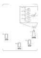
- FIG. 5is a diagram showing an example of beam forming.
- the plurality of antenna elementsare connected to a single transmission unit (TXRU: “Transceiver” unit) 10, controlled in phase by a phase shifter 11 for each antenna element, and transmitted from the antenna element 12 in any direction with respect to the transmission signal.
- TXRUTransmission Unit
- the beamcan be directed.
- TXRUmay be defined as an antenna port, and only the antenna port may be defined in the terminal device 1. Since the directivity can be directed in an arbitrary direction by controlling the phase shifter 11, the base station apparatus 3 can communicate with the terminal apparatus 1 using a beam having a high gain.
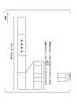
- FIG. 6is a diagram illustrating an example of a synchronization signal block, a synchronization signal burst, and a synchronization signal burst set.
- FIG. 6shows an example in which one synchronization signal burst is included in the synchronization signal burst set, three synchronization signal blocks are included in one synchronization signal burst, and the synchronization signal block is configured by one OFDM symbol. .
- the synchronization signal burst setis composed of one or a plurality of synchronization signal bursts, and one synchronization signal burst is composed of one or a plurality of synchronization signal blocks.
- the synchronization signal blockis composed of time units composed of one or a plurality of consecutive OFDM symbols. Note that the time unit included in the synchronization signal block may be shorter than the OFDM symbol length.
- the synchronization signal burst setmay be transmitted periodically.
- a cycle used for initial access and a cycle set for a connected terminal device(Connected or RRC_Connected) may be defined.
- the period set for the connected terminal device(Connected or RRC_Connected) may be set in the RRC layer.
- the period set for the connected (Connected or RRC_Connected) terminalis a period of radio resources in the time domain that can potentially be transmitted, and is the base station apparatus 3 actually transmitting? You may decide.
- the cycle used for the initial accessmay be defined in advance in a specification or the like.
- the PSS and / or SSS subcarrier interval to be used for initial accessis defined in advance in the specification, and the synchronization signal burst set set for the connected terminal apparatus is a system frame number (SFN: System Frame Number) may be determined. Also, the start position (boundary) of the synchronization signal burst set may be determined based on the SFN and the period.
- SFNSystem Frame Number
- the same beamis applied to the synchronization signal burst or the synchronization signal block having the same relative time in each synchronization signal burst set in the plurality of synchronization signal burst sets.
- the antenna ports in the sync signal burst or sync signal block with the same relative time in each sync signal burst set in the multiple sync signal burst setsare assumed to be QCL with respect to average delay, Doppler shift, and spatial correlation. Also good.
- the relative time position where the synchronization signal burst is arrangedmay be fixed among the plurality of synchronization signal burst sets.
- the synchronization signal burstmay include one or more synchronization signal block numbers in the synchronization signal burst.
- the antenna port of the sync signal block at a certain relative time in the sync signal burst and the antenna port of the sync signal block at the same relative time in the other sync signal bursthave a QCL in terms of average delay, Doppler shift, and spatial correlation. It may be assumed that
- the relative time intervals of the plurality of synchronization signal bursts in the synchronization signal burst setmay be fixed. For example, when the period of the synchronization signal burst set is 15 ms and three synchronization signal bursts are included in the burst set, the synchronization signal burst may be arranged every 5 ms.
- the synchronization signal blockmay be composed of one or more of PSS, SSS, and PBCH.
- PSS, SSS, and PBCHmay be multiplexed (TDM) in the time domain or multiplexed (FDM) in the frequency domain.
- TDMtime domain
- FDMmultiplexed
- One or more of PSS, SSS, and PBCHmay be included in the synchronization signal block.
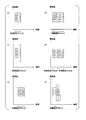
- FIG. 7is a diagram illustrating an example of a method for multiplexing PSS, SSS, and PBCH in a synchronization signal block.
- FIG. 7Ais a diagram illustrating an example in which PSS, SSS, and PBCH are time-multiplexed one by one in one synchronization signal block.
- FIG. 7Bshows a case where PSS, SSS, and PBCH are time-multiplexed in one synchronization signal block and the bandwidth used for PBCH is wide (for example, the number of subcarriers or resource elements of PBCH is PSS and / or Or more than SSS).
- FIG. 7Ais a diagram illustrating an example in which PSS, SSS, and PBCH are time-multiplexed one by one in one synchronization signal block.
- FIG. 7Bshows a case where PSS, SSS, and PBCH are time-multiplexed in one synchronization signal block and the bandwidth used for PBCH is wide (for example, the number of
- FIG. 7Cis a diagram illustrating an example in which time synchronization is performed with PBCH, PSS, SSS, and PBCH in one synchronization signal block.
- the first PBCH and the last PBCH in the synchronization signal blockmay be the same.
- the time order of PSS, SSS, and PBCHmay be the order of PSS, SSS, PBCH, and PBCH.
- FIG. 7Dis a diagram illustrating an example in which the same signal is transmitted twice in the order of PSS, SSS, and PBCH in one synchronization signal block.
- PSS, SSS, and PBCHmay be defined as being arranged in a plurality of time and / or frequency resources.
- PSS, SSS, and PBCHare retransmitted.
- a certain synchronization signal blockmay be defined as being arranged in a plurality of time and / or frequency resources.
- FIG. 7Fshows an example in which PSS, SSS, and PBCH are time-multiplexed in one synchronization signal block, and PBCH transmitted in a bandwidth wider than the bandwidth of PSS and / or SSS is time-multiplexed by two symbols.
- FIG. Time multiplexing and frequency multiplexingmay be defined in combination. For example, PSS and SSS may be multiplexed, and PSS / SSS and PBCH may be multiplexed.
- radio resourcesmay be used.
- radio resources with continuous frequency positionsmay be used, or discontinuous radio resources may be used.
- the number of synchronization signal blocksmay be defined as the number (number) of synchronization signal blocks in a synchronization signal burst, a synchronization signal burst set, or a period of the synchronization signal block, for example. Further, the number of synchronization signal blocks may indicate the number of beam groups for cell selection in a synchronization signal burst, a synchronization signal burst set, or a period of the synchronization signal block.
- a beam groupmay be defined as the number of synchronization signal blocks or different beams included in a synchronization signal burst, or in a synchronization signal burst set, or in the period of a synchronization signal block.
- the fact that the beam of the synchronization signal block transmitted at any two antenna ports is differentmeans that the synchronization signal block is transmitted within the synchronization signal burst, the synchronization signal burst set, or the period of the synchronization signal block. It may be defined that the two antenna ports used are not QCL in terms of spatial parameters. Also, the beam may be defined as a transmission or reception filter setting (Filter Configuration).
- the spatial parametermay include at least one or more of the following: ⁇ Spatial Correlation Reception angle (AoA (Angle of Arrival) and / or ZoA (Zenith angle of Arrival)) Receive angle dispersion (ASA (Angle Spread of Arrival) and / or ZSD (Zenith angle Spread of Arrival)) Launch angle (AoD (Angle of Departure) and / or ZoD (Zenith angle of Departure)) Launch angle dispersion (ASD (Angle Spread of Departure) and / or ZSD (Zenith angle Spread of Departure))
- the synchronization signal blockmay indicate the number of beams in a beam group or synchronization signal burst, or in a synchronization signal burst set, or in the period of the synchronization signal block.
- the sync signal burst or the sync signal burstThe number of beams in the set or in the period of the synchronization signal block is the number of synchronization signal blocks transmitted in the synchronization signal burst.
- the synchronization signal blockis transmitted with the same beam twice. Therefore, the number of beams may be the number of synchronization signal blocks / 2.
- the number of synchronization signal blocks in the synchronization signal burst defined in advance in the specificationmay indicate the maximum number of potential synchronization signal blocks in the synchronization signal burst.
- the synchronization signal burst time length defined in advance by the specificationmay be defined as an integral multiple of the slot or subframe length, or may be a slot length such as 1/2 or 1/3 of the slot length or subframe length, or It may be defined based on the subframe length. Further, it may be defined based on the OFDM symbol length or the minimum time (Ts) instead of the slot length or the subframe length.
- PSS and SSSare generated by M series or Gold series (may be PN series).
- the initial value of the shift registermay be determined based on at least the number of synchronization signal blocks in the synchronization signal burst.
- the initial value of the shift registermay be further based on a cell ID or a value based on the cell ID.
- the parameter for determining the cyclic shift amount or the row index of the Hadamard sequenceis at least the number of synchronization signal blocks in the synchronization signal burst. May be determined based on
- the parameter that determines the amount of click shift or the row index of the Hadamard sequencemay be further based on a cell ID or a value based on the cell ID.
- the number of synchronization signal blocks in the synchronization signal burstmay be included in the MIB or system information transmitted on the PBCH.
- the terminal device 1measures the reception quality of the cell (for example, RSRP, RSRQ, RS-SINR obtained by RRM measurement) from the number of synchronization signal blocks in the synchronization signal burst. At this time, the measurement values may be averaged between the synchronization signal blocks in the synchronization signal burst.
- the reception quality of the cellfor example, RSRP, RSRQ, RS-SINR obtained by RRM measurement
- an average value between X synchronization signal blocks (X may be 1 or X may be an integer of 2 or more) in the synchronization signal burstmay be used as a cell selection measurement. In this case, the number of synchronization signal blocks in the synchronization signal burst may not be indicated.
- the MIB transmitted on the PBCHmay include the time index of the synchronization signal block in the synchronization signal burst, the synchronization signal burst set, or the period of the synchronization signal block. Further, the time index of the synchronization signal block in the synchronization signal burst, or in the synchronization signal burst set, or in the period of the synchronization signal block may be notified by individual RRC signaling.
- the time indexmay be notified by a third signal (for example, TSS (Tertiary Synchronization Signal) or cell-specific CSI-RS (Channel State Information Reference Signal) ID.
- the cell-specific CSI- RSmay be signaled by MIB included in PBCH or SIB included in PDSCH (for example, one or more of CSI-RS period, resource (including time, frequency, code), number of antenna ports)
- TSSwhen transmitted, it may be time-multiplexed with PSS, SSS, and PBCH in the synchronization signal block, or may be frequency-multiplexed. It may be defined as a signal in the block, and CSI-RS may also be transmitted in the synchronization signal block.
- a synchronization signal block arrangement method(localized / contiguous or discrete (Distributed) within a synchronization signal burst, a synchronization signal burst set, or a period of a synchronization signal block). / Non-contiguous)) may be indicated. Further, the arrangement method may be indicated by 1 bit. Moreover, the information regarding the arrangement method may be notified by individual RRC signaling.
- FIG. 8shows an example of the arrangement method of the synchronization signal block.
- FIG. 8Ashows an example in which synchronization signal blocks are locally arranged from the cycle boundary in the time domain.
- FIG. 8Bshows an example in which the synchronization signal blocks are discretely arranged in the period in the time domain.
- the periodmay be set as the period of the synchronization signal burst, the period of the synchronization signal burst set, the period of the synchronization signal block, or the period of the synchronization signal.
- the synchronization signal blockmay be locally defined in time.
- the terminal device 1may assume L consecutive synchronization signal blocks.
- the terminal device 1may receive the synchronization signal blocks by the number or the number of the indicated synchronization signal blocks among the number of L potential synchronization signal blocks.
- the terminal device 1may assume synchronization signal blocks that are discretely arranged in time out of the number of L potential synchronization signal blocks.
- the terminal device 1may assume as many synchronization signal blocks as the number or locations of the indicated synchronization signal blocks among the number of L potential synchronization signal blocks.
- synchronization signal bursts including a plurality of synchronization signal blocksmay be arranged locally or discretely.
- the terminal device 1may perform measurement assuming a continuous synchronization signal block, or may omit resources of the synchronization signal block from the resource elements of the PDSCH.
- L valuemay be defined in the specification. Further, the value of L may be defined in the specification by the frequency band.
- “local”may mean that the synchronization signal block is locally arranged among the candidates for the synchronization signal block in the synchronization signal burst set or the synchronization signal burst. Further, it may mean that a synchronization signal block is arranged in a synchronization signal burst set or a slot to be localized in the synchronization signal burst. Further, it may mean that a synchronization signal burst or a set of a plurality of synchronization signal blocks is locally arranged in the synchronization signal burst set.
- the time position of the synchronization signal block or the synchronization signal burst assumed by the terminal device 1may be set based on the number L of potential synchronization signal blocks or synchronization signal bursts.
- the number of OFDM symbols in one periodis N SC
- the number of symbols included in the synchronization signal block or the synchronization signal burstis S (in the case of the synchronization signal burst, the number of OFDM symbols included in the time domain where the synchronization signal burst is arranged) may also be) as, when the total number of time positions can be placed a synchronization signal block or synchronization signal burst and N SS
- N SSis expressed by the following equation.
- the following expressionis an example in which the synchronization signal blocks are arranged at equal intervals.
- the equationcan be similarly defined in the case of the sync signal burst.
- N (l)indicates the time position of the l-th synchronization signal block.
- lis an index with the time resource of the synchronization signal block as a unit, but may be represented by an OFDM symbol index or a slot index.
- an expression defined so as to match the slot boundary with respect to the value determined in expression (2)may be used. For example, it may be defined as the head of the slot closest to the position represented by Equation (2).
- the terminal device 1may receive the number of instructed actual synchronization signal blocks or the synchronization signal block at the time position.
- FIG. 9shows an example in which a synchronization signal block is arranged in a local slot or a discrete slot as a configuration of a local or discrete synchronization signal block.
- FIG. 9Ashows an example in which the PSS, SSS, and PBCH that are instructed to be local are temporally arranged. As shown in the figure, one synchronization signal block is arranged in each continuous slot. Here, the head of the synchronization signal block is arranged from the third OFDM symbol in the slot. From which OFDM symbol the synchronization signal block is arranged may be defined in the specification.
- FIG. 9Bshows an example of arrangement in discrete slots.
- Nslotthe number of slots contained in a period of the synchronization signal blocks, the number of symbols included in the synchronization signal block S, the total number of time positions can be placed a synchronization signal blocks and N SS, N SS the following formula It is represented by
- the time position of the synchronization signal blockincludes information indicating whether the synchronization signal block is local or discrete, the period of the synchronization signal block, the number of synchronization signal blocks included in the period of the synchronization signal block, and It may be determined by any one or a plurality of the maximum number within the period of the predefined synchronization signal block.
- the time interval between synchronization signal blocks or the period of synchronization signal burstmay be defined in advance as described above, or may be notified by PBCH, SIB, or individual RRC signaling. .
- the period of the synchronization signal blockmay be a synchronization signal burst set or a synchronization signal burst.
- the period of the synchronization signal block and the number of synchronization signal blocks included in the period of the synchronization signal blockmay be set by RRC signaling. Also, these pieces of information may be indicated by the MIB included in the PBCH. Further, if the period of the synchronization signal block is not set, a period defined in advance (for example, a default period) may be used. Further, if the number of synchronization signal blocks included in the cycle of the synchronization signal block is not set, the terminal device 1 may assume the maximum number within the cycle of the synchronization signal block defined in advance.
- bit 1may indicate the time position at which the synchronization signal block was transmitted
- bit 0may indicate the time position at which the synchronization signal block was not transmitted.
- the terminal device 1may assume that bits of a logical synchronization signal block are set by a bit map of length L, and that correspond to a local or discrete physical time position. For example, the terminal device 1 may assume a physical time position based on the bits of the synchronization signal block represented by the bit map having the length L and the above-described local or discrete information.
- the synchronization signal blockis locally and discretely arranged.
- the synchronization signal burst or plural synchronization signal blocksmay be locally and discretely arranged as one unit.
- a method of locally arranging four synchronization signal blocks as one unit and arranging the one unit discretelyis also conceivable.
- a bit mapmay be formed with a synchronization signal burst or a plurality of synchronization signal blocks as one unit.
- the symbol of the physical downlink shared channelis not mapped to the resource element used (corresponding) at the time position of the synchronization signal block set as described above.
- the period of the synchronization signal block(synchronization signal period, synchronization signal burst period, or synchronization signal burst set period) is 20 milliseconds
- the PBCH transmission time interval(TTI: Transmission Time Interval) is 80 milliseconds. Will be described.
- the MIB code bits transmitted by the PBCHare scrambled by the gold sequence.
- SFNsystem frame number
- the MIB code bits transmitted by the PBCHare scrambled by the gold sequence.
- the M sequence(or the M sequence constituting the Gold sequence) may be initialized every 80 milliseconds using the cell ID and the time index of the synchronization signal block.
- a synchronization signal block ID(SS block identifier) is defined from the cell ID detected from the PSS and SSS and the time index or ID of each synchronization signal block by TSS or PBCH, and initialized by the synchronization signal block ID. Good.
- FIG. 10shows an example of the relationship between the time index and the slot with respect to the time position of the synchronization signal block when the synchronization signal is transmitted locally.
- FIG. 10Ashows an example in which one synchronization signal block is arranged in one slot and four synchronization signal blocks are arranged in four slots. As described above, when one synchronization signal block is arranged in one slot, the time index is determined for each slot or each synchronization signal block in the slot.
- FIG. 10Bshows an example in which a plurality of synchronization signal blocks can be arranged in one slot, and eight synchronization signal blocks are arranged in four slots. In the example of FIG. 10B, two synchronization signal blocks are arranged in one slot and are indexed in order from the top.
- the time indexindicates the ID of the synchronization signal block and can also be defined as an indication of the index of the beam.
- the time position of the synchronization signal blockmay be a slot index, a time position in the slot and the slot, or a time index of the synchronization signal block.
- the terminal device 1receives a synchronization signal block at a cycle (for example, 20 milliseconds) defined in advance. After the terminal device 1 camps or connects to the base station device 3, the base station device 3 is instructed to specify the period of the synchronization signal block (or synchronization signal burst or synchronization signal burst set) that the network actually transmits. Good.
- a cyclefor example, 20 milliseconds
- the base station apparatus 3may set whether or not TSS is included in the synchronization signal block.
- the terminal apparatus 1performs RRM measurement (for example, RSRP (Reference Signal Received Power), RSRQ (Reference Signal Received Quality), SS-RSRP (Synchronization Signal Reference Reference Signal Reception Power) or CSI-RSRP (CSI-RS (RSRP), etc.), it is possible to detect the time index of the synchronization signal block or the synchronization signal block ID using the TSS without decoding the PBCH.
- RRM measurementfor example, RSRP (Reference Signal Received Power), RSRQ (Reference Signal Received Quality), SS-RSRP (Synchronization Signal Reference Reference Signal Reception Power) or CSI-RSRP (CSI-RS (RSRP), etc.
- the setting which receives the synchronous signal block of another cell using TSSmay be set via RRC signaling, and may be instruct
- multiplexingmay be performed in any one of the following orders (order of OFDM symbol numbers) within the synchronization signal block.
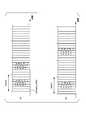
- FIG. 11shows an example when TSS is multiplexed.
- FIG. 11Ashows an example in which synchronous signal blocks are arranged locally and
- FIG. 11Bshows an example in which synchronous signal blocks are discretely arranged.
- the terminal device 1can measure the reception quality of the synchronization signal block without decoding the PBCH.
- the terminal device 1performs initial access using only the PSS, SSS, and PBCH, and the reception quality of the serving cell corresponding to the frequency corresponding to the measurement object by the TSS and the synchronization signal block PSS, SSS, and TSS set at the time of handover. May be measured.
- TSS and CSI-RSmay be set by RRC signaling.
- the terminal device 1receives the PSS, SSS, and TSS in the synchronization signal block.
- TSSis not set, the terminal device 1 receives PSS, SSS, and PBCH in the synchronization signal block.
- the terminal device 1measures based on the PSS, SSS, and TSS when the TSS is set, and measures based on the PSS and SSS when the TSS is not set.
- the measurementmay include measuring the received power (for example, L1-RSRP) for each beam, or may include cell-level RRM measurement.
- a synchronization signal block ID(SS block identifier) is defined based on the PSS, SSS, and TSS.
- PSS and SSSare defined.
- a synchronization signal block identity(SS block identifier) may be defined based on
- TSSwhen TSS is set in the terminal device 1, PDSCH symbols are not mapped to resource elements used for PSS, SSS, and TSS, and when TSS is not set, PSS and SSS are set.
- the physical downlink shared channel symbolis not mapped to the resource element used.
- the terminal device 1when the terminal device 1 receives information on the time position of the synchronization signal block in the period of the synchronization signal block, the time position of the synchronization signal block received by the synchronization signal block includes PSS, SSS, and TSS. As described above, the above-described operation may be applied.
- the terminal device 1may receive the measurement object and perform measurement based on information indicating whether the period of the synchronization signal block included in the measurement object is the same as or different from the serving cell corresponding to the frequency corresponding to the measurement object. For example, when the period of the synchronization signal block is set to be the same as that of the serving cell corresponding to the frequency corresponding to the measurement object, the terminal device 1 assumes the period set in the serving cell and the synchronization signal block of the adjacent cell If the period of synchronization signal block or the maximum number of synchronization signal blocks or the actual number of synchronization signal blocks is set to be different from the serving cell corresponding to the frequency corresponding to the measurement object, the default period or The measurement of the synchronization signal block of the adjacent cell is performed assuming the maximum number of synchronization signal blocks or the actual number of synchronization signal blocks.
- the terminal device 1performs measurement of the synchronization signal block of the adjacent cell assuming the time position set in the serving cell.
- the measurement of the synchronization signal block of the adjacent cellmay be performed assuming the default time position.
- information on whether the time position of the synchronization signal block included in the measurement object is the same as or different from the serving cell corresponding to the frequency corresponding to the measurement objectdoes not include whether the time position of the synchronization signal block is included in the measurement object. It may be the information.
- the measurement objectmay be defined as an object (object) to be measured by the terminal device. Also, for intra-frequency and inter-frequency measurements, a measurement object may be defined to be one NR carrier frequency.
- a measurement objectFor measurement of inter-RAT EUTRA (Evolved Universal Terrestrial Radio Access, also referred to as LTE) ⁇ a measurement object is a single EUTRA carrier frequency or a collection of cells on a single EUTRA carrier frequency May be defined as It is also a set of cells on one UTRA carrier frequency for inter-RAT UTRA (Universal Terrestrial Radio Access, also called WCDMA (registered trademark), HSPA) measurements. May be defined.
- WCDMAUniversal Terrestrial Radio Access
- information indicating the period of the synchronization signal blockis included in the measurement configuration (measurement configuration) including the measurement object, and the synchronization signal block of the frequency (and / or cell) to be measured is included.
- Information indicating whether the period is assumed to be the same as or different from the measurement synchronous block period informationmay be included in the measurement object.
- the measurement setting (measurement configuration) including the measurement objectincludes a plurality of measurement synchronization block cycle information, and the synchronization signal block cycle of the measurement target frequency (and / or cell) is any measurement synchronization block.
- Information indicating whether it is assumed to be periodic informationmay be included in the measurement object.
- the measurement objectmay include information on measurement resources of synchronization signal blocks that can be used for RSRP and RSRQ measurements of neighboring cells at the carrier frequency indicated by the carrier frequency included in the measurement object.
- the terminal device 1may assume that the measurement resource of the synchronization signal block is the same as that of a serving cell (for example, PCell) in all the cells included in the cell list included in the measurement object.
- the measurement resource of the synchronization signal blockmay include one or more of the period, the maximum number of synchronization signal blocks, and the actual number of synchronization signal blocks.
- the measurement objectmay include information related to the measurement resource of the synchronization signal block of the adjacent cell having a certain frequency. For example, one bit may be defined and implemented as follows: -0: Adjacent cell does not have the same synchronization signal block measurement resource as the serving cell-1: The measurement resource of the synchronization signal block of all adjacent cells is the same as the serving cell (identical) Based on the above, the measurement result is reported to the base station apparatus 3.
- One aspect of this embodimentmay be operated in carrier aggregation or dual connectivity with a radio access technology (RAT: “Radio” Access “Technology”) such as LTE or LTE-A / LTE-A Pro.
- RATRadio Access “Technology”
- some or all cells or cell groups, carriers or carrier groupsfor example, primary cell (PCell: Primary Cell), secondary cell (SCell: Secondary Cell), primary secondary cell (PSCell), MCG (Master Cell Group) ), SCG (Secondary Cell Group), etc.
- PCellPrimary Cell
- SCellSecondary Cell
- PSCellprimary secondary cell
- MCGMaster Cell Group
- SCGSecondary Cell Group
- CP-OFDMis applied as the downlink radio transmission scheme
- SC-FDMCP DFTS-OFDM
- FIG. 12is a schematic block diagram showing the configuration of the terminal device 1 of the present embodiment.
- the terminal device 1includes an upper layer processing unit 101, a control unit 103, a receiving unit 105, a transmitting unit 107, and a transmission / reception antenna 109.
- the upper layer processing unit 101includes a radio resource control unit 1011, a scheduling information interpretation unit 1013, and a channel state information (CSI) report control unit 1015.
- the reception unit 105includes a decoding unit 1051, a demodulation unit 1053, a demultiplexing unit 1055, a wireless reception unit 1057, and a measurement unit 1059.
- the transmission unit 107includes an encoding unit 1071, a modulation unit 1073, a multiplexing unit 1075, a radio transmission unit 1077, and an uplink reference signal generation unit 1079.
- the upper layer processing unit 101outputs uplink data (transport block) generated by a user operation or the like to the transmission unit 107.
- the upper layer processing unit 101includes a medium access control (MAC: Medium Access Control) layer, a packet data integration protocol (Packet Data Convergence Protocol: PDCP) layer, a radio link control (Radio Link Control: RLC) layer, and radio resource control. Process the (Radio Resource Control: RRC) layer.
- MACMedium Access Control
- PDCPPacket Data Convergence Protocol
- RLCRadio Link Control
- RRCRadio Resource Control
- the radio resource control unit 1011 included in the upper layer processing unit 101manages various setting information of the own device. Also, the radio resource control unit 1011 generates information arranged in each uplink channel and outputs the information to the transmission unit 107.
- the scheduling information interpretation unit 1013 included in the higher layer processing unit 101interprets the DCI (scheduling information) received via the reception unit 105, and based on the interpretation result of the DCI, the reception unit 105 and the transmission unit 107 In order to perform control, control information is generated and output to the control unit 103.
- DCIscheduling information
- the CSI report control unit 1015instructs the measurement unit 1059 to derive channel state information (RI / PMI / CQI / CRI) related to the CSI reference resource.
- the CSI report control unit 1015instructs the transmission unit 107 to transmit RI / PMI / CQI / CRI.
- the CSI report control unit 1015sets a setting used when the measurement unit 1059 calculates the CQI.
- the control unit 103generates a control signal for controlling the reception unit 105 and the transmission unit 107 based on the control information from the higher layer processing unit 101.
- the control unit 103outputs the generated control signal to the reception unit 105 and the transmission unit 107 to control the reception unit 105 and the transmission unit 107.
- the receiving unit 105separates, demodulates, and decodes the received signal received from the base station apparatus 3 via the transmission / reception antenna 109 according to the control signal input from the control unit 103, and sends the decoded information to the upper layer processing unit 101. Output.
- the radio reception unit 1057converts the downlink signal received via the transmission / reception antenna 109 into an intermediate frequency (down-conversion: down covert), removes unnecessary frequency components, and maintains the signal level appropriately. Then, the amplification level is controlled, quadrature demodulation is performed based on the in-phase component and the quadrature component of the received signal, and the quadrature demodulated analog signal is converted into a digital signal.
- the radio reception unit 1057removes a portion corresponding to a guard interval (Guard Interval: GI) from the converted digital signal, and performs a fast Fourier transform (FFT Fourier Transform: FFT) on the signal from which the guard interval has been removed. Extract the region signal.
- GIGuard Interval
- FFTfast Fourier transform
- the demultiplexing unit 1055separates the extracted signals into downlink PCCH, PSCH, and downlink reference signals. Further, demultiplexing section 1055 performs PCCH and PSCH propagation path compensation based on the propagation path estimation value input from measurement section 1059. Also, the demultiplexing unit 1055 outputs the separated downlink reference signal to the measurement unit 1059.
- Demodulation section 1053demodulates the downlink PCCH and outputs the result to decoding section 1051.
- Decoding section 1051attempts to decode the PCCH, and when decoding is successful, outputs the decoded downlink control information and the RNTI corresponding to the downlink control information to higher layer processing section 101.
- the demodulating unit 1053demodulates the PSCH with the modulation scheme notified by a downlink grant such as QPSK (Quadrature Phase Shift Keying), 16 QAM (Quadrature Amplitude Modulation), 64 QAM, 256 QAM, and the like, and outputs the result to the decoding unit 1051 To do.
- Decoding section 1051performs decoding based on the information related to transmission or original coding rate notified by downlink control information, and outputs the decoded downlink data (transport block) to higher layer processing section 101.
- the measurement unit 1059performs downlink path loss measurement, channel measurement, and / or interference measurement from the downlink reference signal input from the demultiplexing unit 1055.
- the measurement unit 1059outputs the CSI calculated based on the measurement result and the measurement result to the upper layer processing unit 101. Also, measurement section 1059 calculates an estimated value of the downlink propagation path from the downlink reference signal, and outputs it to demultiplexing section 1055.
- the transmission unit 107generates an uplink reference signal according to the control signal input from the control unit 103, encodes and modulates the uplink data (transport block) input from the higher layer processing unit 101, PUCCH, The PUSCH and the generated uplink reference signal are multiplexed and transmitted to the base station apparatus 3 via the transmission / reception antenna 109.
- the encoding unit 1071encodes the uplink control information and the uplink data input from the higher layer processing unit 101.
- the modulation unit 1073modulates the coded bits input from the coding unit 1071 with a modulation scheme such as BPSK, QPSK, 16QAM, 64QAM, and 256QAM.
- the uplink reference signal generation unit 1079is a physical cell identifier for identifying the base station device 3 (referred to as physical cell ⁇ ⁇ identity: ⁇ ⁇ ⁇ PCI, Cell ⁇ ID, etc.), a bandwidth for arranging the uplink reference signal, and an uplink grant.
- a sequence determined by a predetermined ruleis generated based on the notified cyclic shift, the value of a parameter for generating the DMRS sequence, and the like.
- the multiplexing unit 1075determines the number of spatially multiplexed PUSCH layers based on information used for PUSCH scheduling, and uses MIMO spatial multiplexing (MIMO SM: (Multiple Input Multiple Output Spatial Multiplexing) on the same PUSCH.
- MIMO SMMultiple Input Multiple Output Spatial Multiplexing
- a plurality of uplink data to be transmittedis mapped to a plurality of layers, and precoding is performed on the layers.
- the multiplexing unit 1075performs discrete Fourier transform (Discrete-Fourier-Transform: DFT) on the modulation symbols of the PSCH according to the control signal input from the control unit 103. Further, multiplexing section 1075 multiplexes the PCCH and PSCH signals and the generated uplink reference signal for each transmission antenna port. That is, multiplexing section 1075 arranges the PCCH and PSCH signals and the generated uplink reference signal in the resource element for each transmission antenna port.
- DFTdiscrete Fourier transform
- the radio transmission unit 1077performs inverse fast Fourier transform (Inverse Fast Transform: IFFT) on the multiplexed signal, performs SC-FDM modulation, and adds a guard interval to the SC-FDM-modulated SC-FDM symbol.
- IFFTinverse fast Fourier transform
- Generating a baseband digital signalconverting the baseband digital signal to an analog signal, generating an in-phase component and a quadrature component of an intermediate frequency from the analog signal, removing an extra frequency component for the intermediate frequency band,
- the intermediate frequency signalis converted to a high frequency signal (up-conversion: up convert), an extra frequency component is removed, the power is amplified, and output to the transmission / reception antenna 109 for transmission.
- FIG. 13is a schematic block diagram showing the configuration of the base station apparatus 3 of the present embodiment.
- the base station apparatus 3includes an upper layer processing unit 301, a control unit 303, a reception unit 305, a transmission unit 307, and a transmission / reception antenna 309.
- the upper layer processing unit 301includes a radio resource control unit 3011, a scheduling unit 3013, and a CSI report control unit 3015.
- the reception unit 305includes a decoding unit 3051, a demodulation unit 3053, a demultiplexing unit 3055, a wireless reception unit 3057, and a measurement unit 3059.
- the transmission unit 307includes an encoding unit 3071, a modulation unit 3073, a multiplexing unit 3075, a radio transmission unit 3077, and a downlink reference signal generation unit 3079.
- the upper layer processing unit 301includes a medium access control (MAC: Medium Access Control) layer, a packet data integration protocol (Packet Data Convergence Protocol: PDCP) layer, a radio link control (Radio Link Control: RLC) layer, a radio resource control (Radio). Resource (Control: RRC) layer processing. Further, the upper layer processing unit 301 generates control information for controlling the reception unit 305 and the transmission unit 307 and outputs the control information to the control unit 303.
- MACMedium Access Control
- PDCPPacket Data Convergence Protocol
- RLCRadio Link Control
- RadioRadio Resource
- the radio resource control unit 3011 included in the upper layer processing unit 301generates downlink data (transport block), system information, RRC message, MAC CE (Control element), etc. arranged in the downlink PSCH, or higher layer. Obtained from the node and output to the transmission unit 307.
- the radio resource control unit 3011manages various setting information of each terminal device 1.
- the scheduling unit 3013 included in the upper layer processing unit 301uses the received CSI and the channel estimation value, the channel quality, and the like to which the physical channel (PSCH) is allocated based on the channel estimation value and the channel quality. PSCH) transmission coding rate, modulation scheme, transmission power, and the like are determined.
- the scheduling unit 3013generates control information for controlling the reception unit 305 and the transmission unit 307 based on the scheduling result, and outputs the control information to the control unit 303.
- the scheduling unit 3013generates information (for example, DCI (format)) used for physical channel (PSCH) scheduling based on the scheduling result.
- the CSI report control unit 3015provided in the higher layer processing unit 301 controls the CSI report of the terminal device 1.
- the CSI report control unit 3015transmits, to the terminal device 1 via the transmission unit 307, information indicating various settings assumed for the terminal device 1 to derive RI / PMI / CQI in the CSI reference resource.
- the control unit 303generates a control signal for controlling the reception unit 305 and the transmission unit 307 based on the control information from the higher layer processing unit 301.
- the control unit 303outputs the generated control signal to the reception unit 305 and the transmission unit 307 and controls the reception unit 305 and the transmission unit 307.
- the receiving unit 305separates, demodulates and decodes the received signal received from the terminal device 1 via the transmission / reception antenna 309 according to the control signal input from the control unit 303, and outputs the decoded information to the higher layer processing unit 301.
- the radio reception unit 3057converts an uplink signal received via the transmission / reception antenna 309 into an intermediate frequency (down-conversion: down covert), removes unnecessary frequency components, and appropriately maintains the signal level. In this way, the amplification level is controlled, and based on the in-phase and quadrature components of the received signal, quadrature demodulation is performed, and the quadrature demodulated analog signal is converted into a digital signal.
- the wireless receiver 3057removes a portion corresponding to a guard interval (Guard Interval: GI) from the converted digital signal.
- the radio reception unit 3057performs fast Fourier transform (FFT) on the signal from which the guard interval is removed, extracts a frequency domain signal, and outputs the signal to the demultiplexing unit 3055.
- FFTfast Fourier transform
- the demultiplexing unit 1055demultiplexes the signal input from the radio receiving unit 3057 into signals such as PCCH, PSCH, and uplink reference signal. This separation is performed based on radio resource allocation information included in the uplink grant that is determined in advance by the radio resource control unit 3011 by the base station device 3 and notified to each terminal device 1. Further, the demultiplexing unit 3055 compensates the propagation paths of the PCCH and the PSCH from the propagation path estimation value input from the measurement unit 3059. Also, the demultiplexing unit 3055 outputs the separated uplink reference signal to the measurement unit 3059.
- the demodulator 3053performs inverse discrete Fourier transform (Inverse Discrete Fourier Transform: IDFT) to obtain modulation symbols, and BPSK (Binary Shift Keying), QPSK, 16QAM,
- IDFTInverse Discrete Fourier Transform
- BPSKBinary Shift Keying
- QPSK16QAM
- the received signalis demodulated using a predetermined modulation scheme such as 64QAM, 256QAM or the like, or a modulation scheme that the device itself has previously notified to each terminal device 1 with an uplink grant.
- the demodulator 3053uses the MIMO SM based on the number of spatially multiplexed sequences notified in advance to each terminal device 1 using an uplink grant and information indicating precoding performed on the sequences. A plurality of uplink data modulation symbols transmitted on the PSCH are separated.
- the decoding unit 3051transmits the demodulated encoded bits of the PCCH and the PSCH according to a predetermined encoding method, a predetermined transmission method, or a transmission or original signal that the own device has previously notified the terminal device 1 using an uplink grant. Decoding is performed at the coding rate, and the decoded uplink data and uplink control information are output to the upper layer processing section 101. When the PSCH is retransmitted, the decoding unit 3051 performs decoding using the encoded bits held in the HARQ buffer input from the higher layer processing unit 301 and the demodulated encoded bits.
- the measurement unit 3059measures the channel estimation value, channel quality, and the like from the uplink reference signal input from the demultiplexing unit 3055 and outputs the measured values to the demultiplexing unit 3055 and the upper layer processing unit 301.
- the transmission unit 307generates a downlink reference signal according to the control signal input from the control unit 303, encodes and modulates downlink control information and downlink data input from the higher layer processing unit 301, and performs PCCH , PSCH, and downlink reference signal are multiplexed or transmitted with different radio resources to the terminal device 1 via the transmission / reception antenna 309.
- the encoding unit 3071encodes downlink control information and downlink data input from the higher layer processing unit 301.
- the modulation unit 3073modulates the coded bits input from the coding unit 3071 using a modulation scheme such as BPSK, QPSK, 16QAM, 64QAM, and 256QAM.
- the downlink reference signal generation unit 3079generates a known sequence as a downlink reference signal, which is obtained by a predetermined rule based on a physical cell identifier (PCI) for identifying the base station apparatus 3 and the like. To do.
- PCIphysical cell identifier
- the multiplexing unit 3075maps one or more downlink data transmitted on one PSCH to one or more layers according to the number of spatially multiplexed PSCH layers, and the one or more layers Precoding the layer.
- the multiplexing unit 3075multiplexes the downlink physical channel signal and the downlink reference signal for each transmission antenna port.
- the multiplexing unit 3075arranges the downlink physical channel signal and the downlink reference signal in the resource element for each transmission antenna port.
- the wireless transmission unit 3077performs inverse fast Fourier transform (Inverse Fast Fourier Transform: IFFT) on the multiplexed modulation symbols and the like, performs modulation in the OFDM scheme, adds a guard interval to the OFDM symbol that has been OFDM-modulated, and baseband
- IFFTinverse Fast Fourier Transform
- the baseband digital signalis converted to an analog signal, the in-phase and quadrature components of the intermediate frequency are generated from the analog signal, the extra frequency components for the intermediate frequency band are removed, and the intermediate-frequency signal is generated. Is converted to a high-frequency signal (up-conversion: up convert), an extra frequency component is removed, power is amplified, and output to the transmission / reception antenna 309 for transmission.
- the terminal device 1is a terminal device that communicates with a base station device, and includes a first synchronization signal, a second synchronization signal, and a physical broadcast channel.
- a reception unitconfigured to receive and receive first information and second information, wherein the first information includes information for setting a third synchronization signal, and the second information is a period of a synchronization signal block;
- the third synchronization signalis set, the first synchronization signal, the second synchronization signal, and the third synchronization signal are received, and the third synchronization signal is received. Is not set, the first synchronization signal, the second synchronization signal, and the physical broadcast channel are received.
- the synchronization signalwhen the third synchronization signal is set, the synchronization signal is based on the first synchronization signal, the second synchronization signal, and the third synchronization signal.
- a synchronization signal block identityis defined based on the first synchronization signal and the second synchronization signal.
- the reception unitreceives a physical downlink shared channel, and when the third synchronization signal is set, the first synchronization signal and the second synchronization signal are set. If the symbol of the physical downlink shared channel is not mapped to the resource element used for the synchronization signal and the third synchronization signal, and the third synchronization signal is not set, the first synchronization The symbol of the physical downlink shared channel is not mapped to the resource element used for the signal and the second synchronization signal.
- the receiving unitreceives third information, and the third information includes information on a time position of a synchronization signal block in the period, and the time position is , A time index in which the synchronization signal block in the period is arranged.
- the base station apparatus 3 in the second aspect of the present inventionis a base station apparatus that communicates with a terminal apparatus, and transmits a first synchronization signal, a second synchronization signal, and a physical broadcast channel.
- the first informationincludes information for setting a third synchronization signal
- the second informationincludes information indicating a cycle of the synchronization signal block. .
- the synchronization signal blockis based on the first synchronization signal, the second synchronization signal, and the third synchronization signal. If an identity is defined and the third synchronization signal is not set, a synchronization signal block identity is defined based on the first synchronization signal and the second synchronization signal.
- the transmission unittransmits a physical downlink shared channel and sets the third synchronization signal
- the first synchronization signal and the second synchronization signalare set. If the symbol of the physical downlink shared channel is not mapped to the resource element used for the signal and the third synchronization signal, and the third synchronization signal is not set, the first synchronization signal The symbol of the physical downlink shared channel is not mapped to the resource element used for the second synchronization signal.
- the transmission unittransmits third information, and the third information includes information on a time position of a synchronization signal block in the period, and the time position is , A time index in which the synchronization signal block in the period is arranged.
- a communication methodis a communication method of a terminal device, which receives a first synchronization signal, a second synchronization signal, and a physical broadcast channel, and receives first information and second
- the first informationincludes information for setting a third synchronization signal
- the second informationincludes information indicating a period of a synchronization signal block, and the third synchronization signal. Is set, the first synchronization signal, the second synchronization signal, and the third synchronization signal are received, and if the third synchronization signal is not set, the first synchronization signal is received. , The second synchronization signal, and the physical broadcast channel.
- a communication methodis a communication method of a base station apparatus, which transmits a first synchronization signal, a second synchronization signal, and a physical broadcast channel,
- the first informationincludes information for setting a third synchronization signal
- the second informationincludes information indicating a cycle of the synchronization signal block.
- An integrated circuitis an integrated circuit mounted on a terminal device, which receives a first synchronization signal, a second synchronization signal, and a physical broadcast channel, and receives first information
- Receiving means for receiving the second informationthe first information includes information for setting a third synchronization signal
- the second informationincludes information indicating a period of the synchronization signal block
- An integrated circuitis an integrated circuit mounted on a base station apparatus, which transmits a first synchronization signal, a second synchronization signal, and a physical broadcast channel, Transmitting means for transmitting information and second information; and the first information includes information for setting a third synchronization signal, and the second information includes information indicating a cycle of the synchronization signal block. .
- a program that operates on an apparatus according to one aspect of the present inventionis a program that controls a central processing unit (CPU) or the like to function a computer so as to realize the function of the embodiment according to one aspect of the present invention. Also good.
- the program or information handled by the programis temporarily stored in a volatile memory such as a Random Access Memory (RAM), a non-volatile memory such as a flash memory, a Hard Disk Drive (HDD), or other storage system.
- RAMRandom Access Memory
- HDDHard Disk Drive
- a program for realizing the functions of the embodiments according to one aspect of the present inventionmay be recorded on a computer-readable recording medium. You may implement
- the “computer system” hereis a computer system built in the apparatus, and includes hardware such as an operating system and peripheral devices.
- the “computer-readable recording medium”refers to a semiconductor recording medium, an optical recording medium, a magnetic recording medium, a medium that dynamically holds a program for a short time, or other recording medium that can be read by a computer. Also good.
- each functional block or various features of the apparatus used in the above-described embodimentscan be implemented or executed by an electric circuit, for example, an integrated circuit or a plurality of integrated circuits.
- Electrical circuits designed to perform the functions described hereincan be general purpose processors, digital signal processors (DSPs), application specific integrated circuits (ASICs), field programmable gate arrays (FPGAs), or others Programmable logic devices, discrete gate or transistor logic, discrete hardware components, or a combination thereof.
- a general purpose processormay be a microprocessor or a conventional processor, controller, microcontroller, or state machine.
- the electric circuit described abovemay be configured with a digital circuit or an analog circuit.
- one or more aspects of the present inventioncan use a new integrated circuit based on the technology.
- the present inventionis not limited to the above-described embodiment.
- an example of the apparatushas been described.
- the present inventionis not limited to this, and a stationary or non-movable electronic device installed indoors or outdoors, such as an AV device, a kitchen device, It can be applied to terminal devices or communication devices such as cleaning / washing equipment, air conditioning equipment, office equipment, vending machines, and other daily life equipment.
- One embodiment of the present inventionis used in, for example, a communication system, a communication device (for example, a mobile phone device, a base station device, a wireless LAN device, or a sensor device), an integrated circuit (for example, a communication chip), a program, or the like. be able to.
- a communication devicefor example, a mobile phone device, a base station device, a wireless LAN device, or a sensor device
- an integrated circuitfor example, a communication chip
- a programor the like.
- Terminal device 3Base station device 10 Transmission unit 11 Phase shifter 12 Antenna 101 Upper layer processing unit 103 Control unit 105 Reception unit 107 Transmission unit 109 Antenna 301 Upper layer processing unit 303 Control unit 305 Reception unit 307 Transmitter 1011 Radio resource controller 1013 Scheduling information interpreter 1015 Channel state information report controller 1051 Decoder 1053 Demodulator 1055 Demultiplexer 1057 Radio receiver 1059 Measuring unit 1071 Encoder 1073 Modulator 1075 Multiplexer 1077 Radio transmission Unit 1079 uplink reference signal generation unit 3011 radio resource control unit 3013 scheduling unit 3015 channel state information report control unit 3051 decoding unit 3053 demodulation unit 3055 demultiplexing unit 3057 radio reception unit 3059 measurement unit 3 71 encoding unit 3073 modulation unit 3075 multiplexing section 3077 radio transmitting unit 3079 downlink reference signal generator
Landscapes
- Engineering & Computer Science (AREA)
- Signal Processing (AREA)
- Computer Networks & Wireless Communication (AREA)
- Computer Security & Cryptography (AREA)
- Quality & Reliability (AREA)
- Physics & Mathematics (AREA)
- Electromagnetism (AREA)
- Databases & Information Systems (AREA)
- Mobile Radio Communication Systems (AREA)
- Input Circuits Of Receivers And Coupling Of Receivers And Audio Equipment (AREA)
Abstract
Description
Translated fromJapanese 本発明は、基地局装置、端末装置、通信方法、および、集積回路に関する。
本願は、2017年4月27日に日本に出願された特願2017-088206号について優先権を主張し、その内容をここに援用する。The present invention relates to a base station device, a terminal device, a communication method, and an integrated circuit.
This application claims priority on Japanese Patent Application No. 2017-088206 filed in Japan on April 27, 2017, the contents of which are incorporated herein by reference.
現在、第5世代のセルラーシステムに向けた無線アクセス方式および無線ネットワーク技術として、第三世代パートナーシッププロジェクト(3GPP: The Third Generation Partnership Project)において、LTE(Long Term Evolution)-Advanced Pro及びNR(New Radio technology)の技術検討及び規格策定が行われている(非特許文献1)。Currently, the third generation partnership project (3GPP: “The Third Generation Generation Partnership Project”) has developed LTE (Long Term Termination Evolution) -Advanced® Pro and NR (New Radio) as wireless access methods and wireless network technologies for the fifth generation cellular system. technology) and standards are being developed (Non-Patent Document 1).
第5世代のセルラーシステムでは、高速・大容量伝送を実現するeMBB(enhanced Mobile BroadBand)、低遅延・高信頼通信を実現するURLLC(Ultra-Reliable and Low Latency Communication)、IoT(Internet of Things)などマシン型デバイスが多数接続するmMTC(massive Machine Type Communication)の3つがサービスの想定シナリオとして要求されている。In the fifth generation cellular system, eMBB (enhanced Mobile Broadband) that realizes high-speed and large-capacity transmission, URLLC (Ultra-Reliable and Low Latency Communication) that realizes low-latency and high-reliability communication, IoT (Internet-of-Things), etc. There are three service scenarios that require a large number of machine type devices: mmCTC (massive Machine Type Communication).
NRでは、高い周波数で初期アクセスをするための構成およびプロシージャが検討されている(非特許文献2、非特許文献3、非特許文献4)。In NR, configurations and procedures for initial access at a high frequency are being studied (Non-patent
本発明の目的は、上記のような無線通信システムにおいて、基地局装置と端末装置が、効率的に端末装置、基地局装置、通信方法、および、集積回路を提供することを目的とする。An object of the present invention is to provide a terminal device, a base station device, a communication method, and an integrated circuit in which the base station device and the terminal device efficiently in the wireless communication system as described above.
(1)上記の目的を達成するために、本発明の態様は、以下のような手段を講じた。すなわち、本発明の一態様における端末装置は、端末装置であって、第1の情報と第2の情報を受信する上位層処理部と、第1の信号、第2の信号、第3の信号および物理ブロードキャストチャネルを含むブロックを受信する受信部と、を備え、前記第1の情報は、1つまたは複数の前記ブロックの周期を示す情報を含み、前記第2の情報はある時間区間内に含まれる前記1つまたは複数の前記ブロックの時間位置を示す情報を含み、前記第1の信号および前記第2の信号からセルIDを検出し、前記第3の信号から前記ブロックのインデックスを検出する。(1) In order to achieve the above object, the aspect of the present invention takes the following measures. That is, the terminal device according to an aspect of the present invention is a terminal device, and includes an upper layer processing unit that receives the first information and the second information, the first signal, the second signal, and the third signal. And a receiving unit that receives a block including a physical broadcast channel, wherein the first information includes information indicating a period of one or more of the blocks, and the second information is within a certain time interval. Including information indicating time positions of the one or more blocks included, detecting a cell ID from the first signal and the second signal, and detecting an index of the block from the third signal .
(2)また、本発明の一態様における基地局装置は、基地局装置であって、第1の情報と第2の情報を送信する上位層処理部と、第1の信号、第2の信号、第3の信号および物理ブロードキャストチャネルを含むブロックを送信する送信部と、を備え、前記第1の情報は、1つまたは複数の前記ブロックの周期を示す情報を含み、前記第2の情報はある時間区間内に含まれる前記1つまたは複数の前記ブロックの時間位置を示す情報を含み、前記第1の信号および前記第2の信号はセルIDに基づいて定義され、前記第3の信号は前記ブロックのインデックスに基づいて定義される。(2) Moreover, the base station apparatus in 1 aspect of this invention is a base station apparatus, Comprising: The upper layer process part which transmits 1st information and 2nd information, 1st signal, 2nd signal A transmission unit that transmits a block including a third signal and a physical broadcast channel, wherein the first information includes information indicating a period of one or a plurality of the blocks, and the second information is Including information indicating time positions of the one or more blocks included in a certain time interval, wherein the first signal and the second signal are defined based on a cell ID, and the third signal is It is defined based on the index of the block.
(3)また、本発明の一態様における通信方法は、端末装置の通信方法であって、第1の情報と第2の情報を受信し、第1の信号、第2の信号、第3の信号および物理ブロードキャストチャネルを含むブロックを受信し、前記第1の情報は、1つまたは複数の前記ブロックの周期を示す情報を含み、前記第2の情報はある時間区間内に含まれる前記1つまたは複数の前記ブロックの時間位置を示す情報を含み、前記第1の信号および前記第2の信号からセルIDを検出し、前記第3の信号から前記ブロックのインデックスを検出する。(3) Moreover, the communication method in 1 aspect of this invention is a communication method of a terminal device, Comprising: 1st information and 2nd information are received, 1st signal, 2nd signal, 3rd Receiving a block including a signal and a physical broadcast channel, wherein the first information includes information indicating a period of one or more of the blocks, and the second information is included in a certain time interval. Alternatively, it includes information indicating time positions of a plurality of the blocks, detects a cell ID from the first signal and the second signal, and detects an index of the block from the third signal.
(4)また、本発明の一態様における通信方法は、基地局装置の通信方法であって、第1の情報と第2の情報を送信し、第1の信号、第2の信号、第3の信号および物理ブロードキャストチャネルを含むブロックを送信し、前記第1の情報は、1つまたは複数の前記ブロックの周期を示す情報を含み、前記第2の情報はある時間区間内に含まれる前記1つまたは複数の前記ブロックの時間位置を示す情報を含み、前記第1の信号および前記第2の信号はセルIDに基づいて定義され、前記第3の信号は前記ブロックのインデックスに基づいて定義される。(4) Moreover, the communication method in 1 aspect of this invention is a communication method of a base station apparatus, Comprising: 1st information and 2nd information are transmitted, 1st signal, 2nd signal, 3rd The first information includes information indicating a period of one or a plurality of the blocks, and the second information is included in a certain time interval. Including information indicating time positions of one or more of the blocks, wherein the first signal and the second signal are defined based on a cell ID, and the third signal is defined based on an index of the block The
(5)また、本発明の一態様における集積回路は、端末装置に搭載される集積回路であって、第1の情報と第2の情報を受信する上位層処理手段と、第1の信号、第2の信号、第3の信号および物理ブロードキャストチャネルを含むブロックを受信する受信手段と、を備え、前記第1の情報は、1つまたは複数の前記ブロックの周期を示す情報を含み、前記第2の情報はある時間区間内に含まれる前記1つまたは複数の前記ブロックの時間位置を示す情報を含み、前記第1の信号および前記第2の信号からセルIDを検出し、前記第3の信号から前記ブロックのインデックスを検出する。(5) An integrated circuit according to an aspect of the present invention is an integrated circuit mounted on a terminal device, and includes an upper layer processing unit that receives first information and second information, a first signal, Receiving means for receiving a block including a second signal, a third signal and a physical broadcast channel, wherein the first information includes information indicating a period of one or more of the blocks, 2 information includes information indicating the time position of the one or more blocks included in a certain time interval, detects a cell ID from the first signal and the second signal, and the third information The index of the block is detected from the signal.
(6)また、本発明の一態様における集積回路は、基地局装置に搭載される集積回路であって、第1の情報と第2の情報を送信する上位層処理手段と、第1の信号、第2の信号、第3の信号および物理ブロードキャストチャネルを含むブロックを送信する送信手段と、を備え、前記第1の情報は、1つまたは複数の前記ブロックの周期を示す情報を含み、前記第2の情報はある時間区間内に含まれる前記1つまたは複数の前記ブロックの時間位置を示す情報を含み、前記第1の信号および前記第2の信号はセルIDに基づいて定義され、前記第3の信号は前記ブロックのインデックスに基づいて定義される。(6) Moreover, the integrated circuit in 1 aspect of this invention is an integrated circuit mounted in a base station apparatus, Comprising: The upper layer process means which transmits 1st information and 2nd information, 1st signal Transmitting means for transmitting a block including a second signal, a third signal and a physical broadcast channel, wherein the first information includes information indicating a period of one or more of the blocks, Second information includes information indicating a time position of the one or more blocks included in a certain time interval, and the first signal and the second signal are defined based on a cell ID, A third signal is defined based on the index of the block.
この発明の一態様によれば、基地局装置と端末装置が、効率的に通信することができる。According to one aspect of the present invention, the base station device and the terminal device can communicate efficiently.
以下、本発明の実施形態について説明する。Hereinafter, embodiments of the present invention will be described.
図1は、本実施形態における無線通信システムの概念図である。図1において、無線通信システムは、端末装置1A~1C、および基地局装置3を具備する。以下、端末装置1A~1Cを端末装置1とも称する。FIG. 1 is a conceptual diagram of a wireless communication system in the present embodiment. In FIG. 1, the radio communication system includes
端末装置1は、ユーザ端末、移動局装置、通信端末、移動機、端末、UE(User Equipment)、MS(Mobile Station)とも称される。基地局装置3は、無線基地局装置、基地局、無線基地局、固定局、NB(Node B)、eNB(evolved Node B)、BTS(Base Transceiver Station)、BS(Base Station)、NR NB(NR Node B)、NNB、TRP(Transmission and Reception Point)、gNBとも称される。The
図1において、端末装置1と基地局装置3の間の無線通信では、サイクリックプレフィックス(CP: Cyclic Prefix)を含む直交周波数分割多重(OFDM: Orthogonal Frequency Division Multiplexing)、シングルキャリア周波数多重(SC-FDM: Single-Carrier Frequency Division Multiplexing)、離散フーリエ変換拡散OFDM(DFT-S-OFDM: Discrete Fourier Transform Spread OFDM)、マルチキャリア符号分割多重(MC-CDM: Multi-Carrier Code Division Multiplexing)が用いられてもよい。In FIG. 1, in wireless communication between the
また、図1において、端末装置1と基地局装置3の間の無線通信では、ユニバーサルフィルタマルチキャリア(UFMC: Universal-Filtered Multi-Carrier)、フィルタOFDM(F-OFDM: Filtered OFDM)、窓関数が乗算されたOFDM(Windowed OFDM)、フィルタバンクマルチキャリア(FBMC: Filter-Bank Multi-Carrier)が用いられてもよい。In FIG. 1, in wireless communication between the
なお、本実施形態ではOFDMを伝送方式としてOFDMシンボルで説明するが、上述の他の伝送方式の場合を用いた場合も本発明の一態様に含まれる。In this embodiment, OFDM is described as an OFDM transmission system, but the case of using the above-described other transmission system is also included in one aspect of the present invention.
また、図1において、端末装置1と基地局装置3の間の無線通信では、CPを用いない、あるいはCPの代わりにゼロパディングをした上述の伝送方式が用いられてもよい。また、CPやゼロパディングは前方と後方の両方に付加されてもよい。Further, in FIG. 1, in the wireless communication between the
図1において、端末装置1と基地局装置3の間の無線通信では、サイクリックプレフィックス(CP: Cyclic Prefix)を含む直交周波数分割多重(OFDM: Orthogonal Frequency Division Multiplexing)、シングルキャリア周波数多重(SC-FDM: Single-Carrier Frequency Division Multiplexing)、離散フーリエ変換拡散OFDM(DFT-S-OFDM: Discrete Fourier Transform Spread OFDM)、マルチキャリア符号分割多重(MC-CDM: Multi-Carrier Code Division Multiplexing)が用いられてもよい。In FIG. 1, in wireless communication between the
図1において、端末装置1と基地局装置3の無線通信では、以下の物理チャネルが用いられる。
・PBCH(Physical Broadcast CHannel)
・PCCH(Physical Control CHannel)
・PSCH(Physical Shared CHannel)
PBCHは、端末装置1が必要な重要なシステム情報を含む重要情報ブロック(MIB: Master Information Block、EIB: Essential Information Block、BCH:Broadcast Channel)を報知するために用いられる。In FIG. 1, the following physical channels are used in wireless communication between the
・ PBCH (Physical Broadcast CHannel)
・ PCCH (Physical Control CHannel)
・ PSCH (Physical Shared CHannel)
The PBCH is used to broadcast an important information block (MIB: Master Information Block, EIB: Essential Information Block, BCH: Broadcast Channel) including important system information necessary for the
PCCHは、上りリンクの無線通信(端末装置1から基地局装置3の無線通信)の場合には、上りリンク制御情報(Uplink Control Information: UCI)を送信するために用いられる。ここで、上りリンク制御情報には、下りリンクのチャネルの状態を示すために用いられるチャネル状態情報(CSI: Channel State Information)が含まれてもよい。また、上りリンク制御情報には、UL-SCHリソースを要求するために用いられるスケジューリング要求(SR: Scheduling Request)が含まれてもよい。また、上りリンク制御情報には、HARQ-ACK(Hybrid Automatic Repeat request ACKnowledgement)が含まれてもよい。HARQ-ACKは、下りリンクデータ(Transport block, Medium Access Control Protocol Data Unit: MAC PDU, Downlink-Shared Channel: DL-SCH)に対するHARQ-ACKを示してもよい。The PCCH is used for transmitting uplink control information (Uplink 端末 Control Information: 基地 UCI) in the case of uplink wireless communication (wireless communication from the
また、下りリンクの無線通信(基地局装置3から端末装置1への無線通信)の場合には、下りリンク制御情報(Downlink Control Information: DCI)を送信するために用いられる。ここで、下りリンク制御情報の送信に対して、1つまたは複数のDCI(DCIフォーマットと称してもよい)が定義される。すなわち、下りリンク制御情報に対するフィールドがDCIとして定義され、情報ビットへマップされる。In the case of downlink wireless communication (wireless communication from the
例えば、DCIとして、スケジューリングされたPSCHに含まれる信号が下りリンクの無線通信か上りリンクの無線通信か示す情報を含むDCIが定義されてもよい。For example, DCI including information indicating whether a signal included in the scheduled PSCH indicates downlink radio communication or uplink radio communication may be defined as DCI.
例えば、DCIとして、スケジューリングされたPSCHに含まれる下りリンクの送信期間を示す情報を含むDCIが定義されてもよい。For example, DCI including information indicating a downlink transmission period included in the scheduled PSCH may be defined as DCI.
例えば、DCIとして、スケジューリングされたPSCHに含まれる上りリンクの送信期間を示す情報を含むDCIが定義されてもよい。For example, DCI including information indicating an uplink transmission period included in the scheduled PSCH may be defined as DCI.
例えば、DCIとして、スケジューリングされたPSCHに対するHARQ-ACKを送信するタイミング(例えば、PSCHに含まれる最後のシンボルからHARQ-ACK送信までのシンボル数)示す情報を含むDCIが定義されてもよい。For example, DCI including information indicating the timing of transmitting HARQ-ACK for the scheduled PSCH (for example, the number of symbols from the last symbol included in the PSCH to HARQ-ACK transmission) may be defined as DCI.
例えば、DCIとして、スケジューリングされたPSCHに含まれる下りリンクの送信期間、ギャップ、及び上りリンクの送信期間を示す情報を含むDCIが定義されてもよい。For example, DCI including information indicating the downlink transmission period, gap, and uplink transmission period included in the scheduled PSCH may be defined as DCI.
例えば、DCIとして、1つのセルにおける1つの下りリンクの無線通信PSCH(1つの下りリンクトランスポートブロックの送信)のスケジューリングのために用いられるDCIが定義されてもよい。For example, DCI used for scheduling of one downlink radio communication PSCH (transmission of one downlink transport block) in one cell may be defined as DCI.
例えば、DCIとして、1つのセルにおける1つの上りリンクの無線通信PSCH(1つの上りリンクトランスポートブロックの送信)のスケジューリングのために用いられるDCIが定義されてもよい。For example, DCI used for scheduling of one uplink radio communication PSCH (transmission of one uplink transport block) in one cell may be defined as DCI.
ここで、DCIには、PSCHに上りリンクまたは下りリンクが含まれる場合にPSCHのスケジューリングに関する情報が含まれる。ここで、下りリンクに対するDCIを、下りリンクグラント(downlink grant)、または、下りリンクアサインメント(downlink assignment)とも称する。ここで、上りリンクに対するDCIを、上りリンクグラント(uplink grant)、または、上りリンクアサインメント(Uplink assignment)とも称する。Here, DCI includes information on PSCH scheduling when the PSCH includes an uplink or a downlink. Here, the DCI for the downlink is also referred to as a downlink grant (downlink grant) or a downlink assignment (downlink assignment). Here, the DCI for the uplink is also called an uplink grant (uplink grant) or an uplink assignment (Uplink assignment).
PSCHは、媒介アクセス(MAC: Medium Access Control)からの上りリンクデータ(UL-SCH: Uplink Shared CHannel)または下りリンクデータ(DL-SCH: Downlink Shared CHannel)の送信に用いられる。また、下りリンクの場合にはシステム情報(SI: System Information)やランダムアクセス応答(RAR: Random Access Response)などの送信にも用いられる。上りリンクの場合には、上りリンクデータと共にHARQ-ACKおよび/またはCSIを送信するために用いられてもよい。また、CSIのみ、または、HARQ-ACKおよびCSIのみを送信するために用いられてもよい。すなわち、UCIのみを送信するために用いられてもよい。The PSCH is used for transmission of uplink data (UL-SCH: Uplink Shared CHannel) or downlink data (DL-SCH: Downlink Shared CHannel) from mediated access (MAC: Medium Access Control). In downlink, it is also used for transmission of system information (SI: System Information), random access response (RAR: System Random Access, Response), and the like. In the case of uplink, it may be used to transmit HARQ-ACK and / or CSI along with uplink data. Further, it may be used to transmit only CSI or only HARQ-ACK and CSI. That is, it may be used to transmit only UCI.
ここで、基地局装置3と端末装置1は、上位層(higher layer)において信号をやり取り(送受信)する。例えば、基地局装置3と端末装置1は、無線リソース制御(RRC: Radio Resource Control)層において、RRCシグナリング(RRC message: Radio Resource Control message、RRC information: Radio Resource Control informationとも称される)を送受信してもよい。また、基地局装置3と端末装置1は、MAC(Medium Access Control)層において、MACコントロールエレメントを送受信してもよい。ここで、システム情報(ブロードキャスト信号など)、RRCシグナリング、および/または、MACコントロールエレメントを、上位層の信号(higher layer signaling)とも称する。Here, the
PSCHは、システム情報、RRCシグナリング、および/または、MACコントロールエレメントを送信するために用いられてもよい。ここで、基地局装置3から送信されるRRCシグナリングは、セル内における複数の端末装置1に対して共通のシグナリングであってもよい。また、基地局装置3から送信されるRRCシグナリングは、ある端末装置1に対して専用のシグナリング(dedicated signalingとも称する)であってもよい。すなわち、端末装置固有(UEスペシフィック)な情報は、ある端末装置1に対して専用のシグナリングを用いて送信されてもよい。PSCHは、上りリンクに置いてUEの能力(UE Capability)の送信に用いられてもよい。PSCH may be used to transmit system information, RRC signaling, and / or MAC control elements. Here, the RRC signaling transmitted from the
なお、PCCHおよびPSCHは下りリンクと上りリンクで同一の呼称を用いているが、下りリンクと上りリンクで異なるチャネルが定義されてもよい。In addition, although the same name is used for the downlink and the uplink for the PCCH and the PSCH, different channels may be defined for the downlink and the uplink.
例えば、下りリンクの共有チャネルは、物理下りリンク共有チャネル(PDSCH:Physical Downlink Shared CHannel)と称されてよい。また、上りリンクの共有チャネルは物理上りリンク共有チャネル(PUSCH:Physical Uplink Shared CHannel)と称されてよい。また、下りリンクの制御チャネルは物理下りリンク制御チャネル(PDCCH:Physical Downlink Control CHannel)と称されてよい。上りリンクの制御チャネルは物理上りリンク制御チャネル(PUCCH:Physical Uplink Control CHannel)と称されてよい。For example, the downlink shared channel may be referred to as a physical downlink shared channel (PDSCH: Physical Downlink Shared CHannel). Further, the uplink shared channel may be referred to as a physical uplink shared channel (PUSCH: Physical-Uplink-Shared-CHannel). Also, the downlink control channel may be referred to as a physical downlink control channel (PDCCH: Physical Downlink Control CHannel). The uplink control channel may be referred to as a physical uplink control channel (PUCCH: Physical-Uplink-Control-CHannel).
図1において、下りリンクの無線通信では、以下の下りリンク物理信号が用いられる。ここで、下りリンク物理信号は、上位層から出力された情報を送信するために使用されないが、物理層によって使用される。
・同期信号(Synchronization signal: SS)
・参照信号(Reference Signal: RS)
同期信号は、プライマリ同期信号(PSS:Primary Synchronization Signal)および/またはセカンダリ同期信号(SSS)を含んでよい。PSSとSSSを用いてセルIDが検出されてよい。In FIG. 1, the following downlink physical signals are used in downlink wireless communication. Here, the downlink physical signal is not used for transmitting information output from the upper layer, but is used by the physical layer.
・ Synchronization signal (SS)
・ Reference signal (RS)
The synchronization signal may include a primary synchronization signal (PSS) and / or a secondary synchronization signal (SSS). The cell ID may be detected using PSS and SSS.
同期信号は、端末装置1が下りリンクの周波数領域および/または時間領域の同期をとるために用いられる。ここで、同期信号は、端末装置1が基地局装置3によるプリコーディングまたはビームフォーミングにおけるプリコーディングまたはビームの選択に用いられて良い。The synchronization signal is used for the
参照信号は、端末装置1が物理チャネルの伝搬路補償を行うために用いられる。ここで、参照信号は、端末装置1が下りリンクのCSIを算出するためにも用いられてよい。また、参照信号は、無線パラメータやサブキャリア間隔などのヌメロロジーやFFTの窓同期などができる程度の細かい同期(Fine synchronization)に用いられて良い。The reference signal is used for the
本実施形態において、以下の下りリンク参照信号のいずれか1つまたは複数が用いられる。In the present embodiment, any one or more of the following downlink reference signals are used.
・DMRS(Demodulation Reference Signal)
・CSI-RS(Channel State Information Reference Signal)
・PTRS(Phase Tracking Reference Signal)
・MRS(Mobility Reference Signal
DMRSは、変調信号を復調するために使用される。なお、DMRSには、PBCHを復調するための参照信号と、PSCHを復調するための参照信号の2種類が定義されてもよいし、両方をDMRSと称してもよい。CSI-RSは、チャネル状態情報(CSI:Channel State Information)の測定および/またはビームマネジメントに使用される。PTRSは、端末の移動等により位相をトラックするために使用される。MRSは、ハンドオーバのための複数の基地局装置からの受信品質を測定するために使用されてよい。また、参照信号には、位相雑音を補償するための参照信号が定義されてもよい。DMRS (Demodulation Reference Signal)
・ CSI-RS (Channel State Information Reference Signal)
・ PTRS (Phase Tracking Reference Signal)
・ MRS (Mobility Reference Signal
DMRS is used to demodulate the modulated signal. In DMRS, two types of reference signals for demodulating PBCH and reference signals for demodulating PSCH may be defined, or both may be referred to as DMRS. The CSI-RS is used for channel state information (CSI) measurement and / or beam management. PTRS is used to track the phase due to the movement of the terminal or the like. MRS may be used to measure reception quality from multiple base station devices for handover. In addition, a reference signal for compensating for phase noise may be defined in the reference signal.
下りリンク物理チャネルおよび/または下りリンク物理シグナルを総称して、下りリンク信号と称する。上りリンク物理チャネルおよび/または上りリンク物理シグナルを総称して、上りリンク信号と称する。下りリンク物理チャネルおよび/または上りリンク物理チャネルを総称して、物理チャネルと称する。下りリンク物理シグナルおよび/または上りリンク物理シグナルを総称して、物理シグナルと称する。A downlink physical channel and / or a downlink physical signal are collectively referred to as a downlink signal. Uplink physical channels and / or uplink physical signals are collectively referred to as uplink signals. A downlink physical channel and / or an uplink physical channel are collectively referred to as a physical channel. A downlink physical signal and / or an uplink physical signal are collectively referred to as a physical signal.
BCH、UL-SCHおよびDL-SCHは、トランスポートチャネルである。媒体アクセス制御(MAC:Medium Access Control)層で用いられるチャネルをトランスポートチャネルと称する。MAC層で用いられるトランスポートチャネルの単位を、トランスポートブロック(TB:transport block)および/またはMAC PDU(Protocol Data Unit)とも称する。MAC層においてトランスポートブロック毎にHARQ(Hybrid Automatic Repeat reQuest)の制御が行われる。トランスポートブロックは、MAC層が物理層に渡す(deliver)データの単位である。物理層において、トランスポートブロックはコードワードにマップされ、コードワード毎に符号化処理が行われる。BCH, UL-SCH and DL-SCH are transport channels. A channel used in a medium access control (MAC) layer is referred to as a transport channel. A transport channel unit used in the MAC layer is also referred to as a transport block (TB) and / or a MAC PDU (Protocol Data Unit). In the MAC layer, HARQ (HybridbrAutomatic Repeat reQuest) is controlled for each transport block. The transport block is a unit of data that the MAC layer delivers to the physical layer. In the physical layer, the transport block is mapped to a code word, and an encoding process is performed for each code word.
また、参照信号は、無線リソース測定(RRM:Radio Resource Measurement)に用いられてよい。また、参照信号は、ビームマネジメントに用いられてよい。Also, the reference signal may be used for radio resource measurement (RRM: Radio Resource Measurement). The reference signal may be used for beam management.
ビームマネジメントは、送信装置(下りリンクの場合は基地局装置3であり、上りリンクの場合は端末装置1である)におけるアナログおよび/またはディジタルビームと、受信装置(下りリンクの場合は端末装置1、上りリンクの場合は基地局装置3である)におけるアナログおよび/またはディジタルビームの指向性を合わせ、ビーム利得を獲得するための基地局装置3および/または端末装置1の手続きであってよい。Beam management includes analog and / or digital beams in a transmitting device (
なお、ビームペアリンクを構成、設定または確立する手続きとして、下記の手続きを含んでよい。
・ビーム選択(Beam selection)
・ビーム改善(Beam refinement)
・ビームリカバリ(Beam recovery)
例えば、ビーム選択は、基地局装置3と端末装置1の間の通信においてビームを選択する手続きであってよい。また、ビーム改善は、さらに利得の高いビームの選択、あるいは端末装置1の移動によって最適な基地局装置3と端末装置1の間のビームの変更をする手続きであってよい。ビームリカバリは、基地局装置3と端末装置1の間の通信において遮蔽物や人の通過などにより生じるブロッケージにより通信リンクの品質が低下した際にビームを再選択する手続きであってよい。Note that the following procedure may be included as a procedure for configuring, setting or establishing the beam pair link.
・ Beam selection
・ Beam refinement
・ Beam recovery
For example, the beam selection may be a procedure for selecting a beam in communication between the
ビームマネジメントには、ビーム選択、ビーム改善が含まれてよい。ビームリカバリには、下記の手続きを含んでよい。
・ビーム失敗(beam failure)の検出
・新しいビームの発見
・ビームリカバリリクエストの送信
・ビームリカバリリクエストに対する応答のモニタ
例えば、端末装置1における基地局装置3の送信ビームを選択する際にCSI-RSまたは同期信号ブロック内の同期信号(例えば、SSS)を用いてもよいし、擬似同位置(QCL:Quasi Co-Location)想定を用いてもよい。Beam management may include beam selection, beam improvement. Beam recovery may include the following procedures.
-Detection of beam failure-Discovery of new beam-Transmission of beam recovery request-Monitoring of response to beam recovery request For example, when selecting a transmission beam of the
もしあるアンテナポートにおけるあるシンボルが搬送されるチャネルの長区間特性(Long Term Property)が他方のアンテナポートにおけるあるシンボルが搬送されるチャネルから推論されうるなら、2つのアンテナポートはQCLであるといわれる。チャネルの長区間特性は、遅延スプレッド、ドップラースプレッド、ドップラーシフト、平均利得、及び平均遅延の1つまたは複数を含む。例えば、アンテナポート1とアンテナポート2が平均遅延に関してQCLである場合、アンテナポート1の受信タイミングからアンテナポート2の受信タイミングが推論されうることを意味する。Two antenna ports are said to be QCL if the long term property of a channel carrying a symbol at one antenna port can be inferred from the channel carrying a symbol at the other antenna port. . The long-term characteristics of the channel include one or more of delay spread, Doppler spread, Doppler shift, average gain, and average delay. For example, when
このQCLは、ビームマネジメントにも拡張されうる。そのために、空間に拡張したQCLが新たに定義されてもよい。例えば、空間のQCL想定におけるチャネルの長区間特性(Long term property)として、無線リンクあるいはチャネルにおける到来角(AoA(Angle of Arrival), ZoA(Zenith angle of Arrival)など)および/または角度広がり(Angle Spread、例えばASA(Angle Spread of Arrival)やZSA(Zenith angle Spread of Arrival))、送出角(AoD, ZoDなど)やその角度広がり(Angle Spread、例えばASD(Angle Spread of Departure)やZSS(Zenith angle Spread of Departure))、空間相関(Spatial Correlation)であってもよい。This QCL can be extended to beam management. Therefore, a QCL extended to a space may be newly defined. For example, the long-term characteristics (Long に お け る term property) of a channel in a spatial QCL assumption include arrival angles (AoA (Angle of Arrival), ZoA (Zenith angle of Arrival), etc.) and / or angular spread (Angle) Spread, eg ASA (Angle Spread of Arrival) or ZSA (Zenith angle Spread of Arrival)), sending angle (AoD, ZoD, etc.) and its angular spread (Angle Spread, eg ASD (Angle Spread of Departure) or ZSS (Zenith angle) Spread of Departure)) or spatial (correlation.
この方法により、ビームマネジメントとして、空間のQCL想定と無線リソース(時間および/または周波数)によりビームマネジメントと等価な基地局装置3、端末装置1の動作が定義されてもよい。By this method, the operations of the
以下、サブフレームについて説明する。本実施形態ではサブフレームと称するが、リソースユニット、無線フレーム、時間区間、時間間隔などと称されてもよい。Hereinafter, subframes will be described. Although referred to as a subframe in this embodiment, it may be referred to as a resource unit, a radio frame, a time interval, a time interval, or the like.
図2は、本発明の第1の実施形態に係る下りリンクスロットの概略構成の一例を示す図である。無線フレームのそれぞれは、10ms長である。また、無線フレームのそれぞれは10個のサブフレームおよびX個のスロットから構成される。つまり、1サブフレームの長さは1msである。スロットのそれぞれは、サブキャリア間隔によって時間長が定義される。例えば、OFDMシンボルのサブキャリア間隔が15kHz、NCP(Normal Cyclic Prefix)の場合、X=7あるいはX=14であり、それぞれ0.5msおよび1msである。また、サブキャリア間隔が60kHzの場合は、X=7あるいはX=14であり、それぞれ0.125msおよび0.25msである。図2は、X=7の場合を一例として示している。なお、X=14の場合にも同様に拡張できる。また、上りリンクスロットも同様に定義され、下りリンクスロットと上りリンクスロットは別々に定義されてもよい。FIG. 2 is a diagram illustrating an example of a schematic configuration of a downlink slot according to the first embodiment of the present invention. Each radio frame is 10 ms long. Each radio frame is composed of 10 subframes and X slots. That is, the length of one subframe is 1 ms. Each slot has a time length defined by a subcarrier interval. For example, when the subcarrier interval of the OFDM symbol is 15 kHz and NCP (Normal Cyclic Prefix), X = 7 or X = 14, which is 0.5 ms and 1 ms, respectively. When the subcarrier interval is 60 kHz, X = 7 or X = 14, which are 0.125 ms and 0.25 ms, respectively. FIG. 2 shows an example where X = 7. Note that the same extension can be made when X = 14. Further, the uplink slot is defined in the same manner, and the downlink slot and the uplink slot may be defined separately.
スロットのそれぞれにおいて送信される信号または物理チャネルは、リソースグリッドによって表現されてよい。リソースグリッドは、複数のサブキャリアと複数のOFDMシンボルによって定義される。1つのスロットを構成するサブキャリアの数は、セルの下りリンクおよび上りリンクの帯域幅にそれぞれ依存する。リソースグリッド内のエレメントのそれぞれをリソースエレメントと称する。リソースエレメントは、サブキャリアの番号とOFDMシンボルの番号とを用いて識別されてよい。The signal or physical channel transmitted in each of the slots may be represented by a resource grid. The resource grid is defined by a plurality of subcarriers and a plurality of OFDM symbols. The number of subcarriers constituting one slot depends on the downlink and uplink bandwidths of the cell. Each element in the resource grid is referred to as a resource element. Resource elements may be identified using subcarrier numbers and OFDM symbol numbers.
リソースブロックは、ある物理下りリンクチャネル(PDSCHなど)あるいは上りリンクチャネル(PUSCHなど)のリソースエレメントのマッピングを表現するために用いられる。リソースブロックは、仮想リソースブロックと物理リソースブロックが定義される。ある物理上りリンクチャネルは、まず仮想リソースブロックにマップされる。その後、仮想リソースブロックは、物理リソースブロックにマップされる。スロットに含まれるOFDMシンボル数X=7で、NCPの場合には、1つの物理リソースブロックは、時間領域において7個の連続するOFDMシンボルと周波数領域において12個の連続するサブキャリアとから定義される。つまり、1つの物理リソースブロックは、(7×12)個のリソースエレメントから構成される。ECP(Extended CP)の場合、1つの物理リソースブロックは、例えば、時間領域において6個の連続するOFDMシンボルと、周波数領域において12個の連続するサブキャリアとにより定義される。つまり、1つの物理リソースブロックは、(6×12)個のリソースエレメントから構成される。このとき、1つの物理リソースブロックは、時間領域において1つのスロットに対応し、15kHzのサブキャリア間隔の場合、周波数領域において180kHz(60kHzの場合には720kHz)に対応する。物理リソースブロックは、周波数領域において0から番号が付けられている。The resource block is used to express a mapping of resource elements of a certain physical downlink channel (PDSCH or the like) or uplink channel (PUSCH or the like). As resource blocks, virtual resource blocks and physical resource blocks are defined. A physical uplink channel is first mapped to a virtual resource block. Thereafter, the virtual resource block is mapped to the physical resource block. In the case of NCP in which the number of OFDM symbols included in a slot is X = 7, one physical resource block is defined by 7 consecutive OFDM symbols in the time domain and 12 consecutive subcarriers in the frequency domain. The That is, one physical resource block is composed of (7 × 12) resource elements. In the case of ECP (Extended CP), one physical resource block is defined by, for example, 6 consecutive OFDM symbols in the time domain and 12 consecutive subcarriers in the frequency domain. That is, one physical resource block is composed of (6 × 12) resource elements. At this time, one physical resource block corresponds to one slot in the time domain, and corresponds to 180 kHz (720 kHz in the case of 60 kHz) in the frequency domain when the subcarrier interval is 15 kHz. Physical resource blocks are numbered from 0 in the frequency domain.
次に、サブフレーム、スロット、ミニスロットについて説明する。図3は、サブフレーム、スロット、ミニスロットの時間領域における関係を示した図である。同図のように、3種類の時間ユニットが定義される。サブフレームは、サブキャリア間隔によらず1msであり、スロットに含まれるOFDMシンボル数は7または14であり、スロット長はサブキャリア間隔により異なる。ここで、サブキャリア間隔が15kHzの場合、1サブフレームには14OFDMシンボル含まれる。そのため、スロット長は、サブキャリア間隔をΔf(kHz)とすると、1スロットを構成するOFDMシンボル数が7の場合、スロット長は0.5/(Δf/15)msで定義されてよい。ここで、Δfはサブキャリア間隔(kHz)で定義されてよい。また、1スロットを構成するOFDMシンボル数が7の場合、スロット長は1/(Δf/15)msで定義されてよい。ここで、Δfはサブキャリア間隔(kHz)で定義されてよい。さらに、スロットに含まれるOFDMシンボル数をXとしたときに、スロット長はX/14/(Δf/15)msで定義されてもよい。Next, subframes, slots, and minislots will be described. FIG. 3 is a diagram illustrating the relationship in the time domain between subframes, slots, and minislots. As shown in the figure, three types of time units are defined. The subframe is 1 ms regardless of the subcarrier interval, the number of OFDM symbols included in the slot is 7 or 14, and the slot length varies depending on the subcarrier interval. Here, when the subcarrier interval is 15 kHz, 14 OFDM symbols are included in one subframe. Therefore, the slot length may be defined as 0.5 / (Δf / 15) ms when the number of OFDM symbols constituting one slot is 7, where the subcarrier interval is Δf (kHz). Here, Δf may be defined by a subcarrier interval (kHz). When the number of OFDM symbols constituting one slot is 7, the slot length may be defined as 1 / (Δf / 15) ms. Here, Δf may be defined by a subcarrier interval (kHz). Further, when the number of OFDM symbols included in the slot is X, the slot length may be defined as X / 14 / (Δf / 15) ms.
ミニスロット(サブスロットと称されてもよい)は、スロットに含まれるOFDMシンボル数よりも少ないOFDMシンボルで構成される時間ユニットである。同図はミニスロットが2OFDMシンボルで構成される場合を一例として示している。ミニスロット内のOFDMシンボルは、スロットを構成するOFDMシンボルタイミングに一致してもよい。なお、スケジューリングの最小単位はスロットまたはミニスロットでよい。また、
図4は、スロットまたはサブフレームの一例を示す図である。ここでは、サブキャリア間隔15kHzにおいてスロット長が0.5msの場合を例として示している。同図において、Dは下りリンク、Uは上りリンクを示している。同図に示されるように、ある時間区間内(例えば、システムにおいて1つのUEに対して割り当てなければならない最小の時間区間)においては、
・下りリンクパート(デュレーション)
・ギャップ
・上りリンクパート(デュレーション)のうち1つまたは複数を含んでよい。A mini-slot (which may be referred to as a sub-slot) is a time unit configured with fewer OFDM symbols than the number of OFDM symbols included in the slot. This figure shows an example in which a minislot is composed of 2 OFDM symbols. The OFDM symbols in the minislot may coincide with the OFDM symbol timing that constitutes the slot. The minimum scheduling unit may be a slot or a minislot. Also,
FIG. 4 is a diagram illustrating an example of a slot or a subframe. Here, a case where the slot length is 0.5 ms at a subcarrier interval of 15 kHz is shown as an example. In the figure, D indicates the downlink and U indicates the uplink. As shown in the figure, within a certain time interval (for example, the minimum time interval that must be allocated to one UE in the system),
・ Downlink part (duration)
One or more of the gap and the uplink part (duration) may be included.
図4(a)は、ある時間区間(例えば、1UEに割当可能な時間リソースの最小単位、またはタイムユニットなどとも称されてよい。また、時間リソースの最小単位を複数束ねてタイムユニットと称されてもよい。)で、全て下りリンク送信に用いられている例であり、図4(b)は、最初の時間リソースで例えばPCCHを介して上りリンクのスケジューリングを行い、PCCHの処理遅延及び下りから上りの切り替え時間、送信信号の生成のためのギャップを介して上りリンク信号を送信する。図4(c)は、最初の時間リソースで下りリンクのPCCHおよび/または下りリンクのPSCHの送信に用いられ、処理遅延及び下りから上りの切り替え時間、送信信号の生成のためのギャップを介してPSCHまたはPCCHの送信に用いられる。ここで、一例としては、上りリンク信号はHARQ-ACKおよび/またはCSI、すなわちUCIの送信に用いられてよい。図4(d)は、最初の時間リソースで下りリンクのPCCHおよび/または下りリンクのPSCHの送信に用いられ、処理遅延及び下りから上りの切り替え時間、送信信号の生成のためのギャップを介して上りリンクのPSCHおよび/またはPCCHの送信に用いられる。ここで、一例としては、上りリンク信号は上りリンクデータ、すなわちUL-SCHの送信に用いられてもよい。図4(e)は、全て上りリンク送信(上りリンクのPSCHまたはPCCH)に用いられている例である。4A may be referred to as a certain time interval (for example, a minimum unit of time resources that can be allocated to one UE, or a time unit, etc. In addition, a plurality of minimum units of time resources are bundled to be referred to as a time unit. 4 (b) is an example in which all are used for downlink transmission, and FIG. 4 (b) performs uplink scheduling via the PCCH, for example, with the first time resource, and the processing delay and downlink of the PCCH. Uplink signal is transmitted through the uplink switching time and the gap for generating the transmission signal. FIG. 4 (c) is used for transmission of the downlink PCCH and / or downlink PSCH in the first time resource, through the processing delay, the downlink to uplink switching time, and the gap for transmission signal generation. Used for transmission of PSCH or PCCH. Here, as an example, the uplink signal may be used for transmission of HARQ-ACK and / or CSI, that is, UCI. FIG. 4 (d) is used for transmission of downlink PCCH and / or downlink PSCH in the first time resource, via processing delay, downlink to uplink switching time, and gap for transmission signal generation. Used for uplink PSCH and / or PCCH transmission. Here, as an example, the uplink signal may be used for transmission of uplink data, that is, UL-SCH. FIG. 4E is an example in which all are used for uplink transmission (uplink PSCH or PCCH).
上述の下りリンクパート、上りリンクパートは、LTEと同様複数のOFDMシンボルで構成されてよい。The above-described downlink part and uplink part may be composed of a plurality of OFDM symbols as in LTE.
図5は、ビームフォーミングの一例を示した図である。複数のアンテナエレメントは1つの送信ユニット(TXRU: Transceiver unit)10に接続され、アンテナエレメント毎の位相シフタ11によって位相を制御し、アンテナエレメント12から送信することで送信信号に対して任意の方向にビームを向けることができる。典型的には、TXRUがアンテナポートとして定義されてよく、端末装置1においてはアンテナポートのみが定義されてよい。位相シフタ11を制御することで任意の方向に指向性を向けることができるため、基地局装置3は端末装置1に対して利得の高いビームを用いて通信することができる。FIG. 5 is a diagram showing an example of beam forming. The plurality of antenna elements are connected to a single transmission unit (TXRU: “Transceiver” unit) 10, controlled in phase by a
図6は、同期信号ブロック、同期信号バースト、同期信号バーストセットの例を示す図である。図6は、同期信号バーストセット内に1つの同期信号バーストが含まれ、1つの同期信号バーストに3つの同期信号ブロックが含まれ、同期信号ブロックは、1OFDMシンボルで構成される例を示している。FIG. 6 is a diagram illustrating an example of a synchronization signal block, a synchronization signal burst, and a synchronization signal burst set. FIG. 6 shows an example in which one synchronization signal burst is included in the synchronization signal burst set, three synchronization signal blocks are included in one synchronization signal burst, and the synchronization signal block is configured by one OFDM symbol. .
同期信号バーストセットは、1つまたは複数の同期信号バーストから構成され、1つの同期信号バーストは、1つまたは複数の同期信号ブロックから構成される。同期信号ブロックは、1または複数の連続するOFDMシンボルから構成されるタイムユニットから構成される。なお、同期信号ブロックに含まれるタイムユニットは、OFDMシンボル長より短くてもよい。The synchronization signal burst set is composed of one or a plurality of synchronization signal bursts, and one synchronization signal burst is composed of one or a plurality of synchronization signal blocks. The synchronization signal block is composed of time units composed of one or a plurality of consecutive OFDM symbols. Note that the time unit included in the synchronization signal block may be shorter than the OFDM symbol length.
同期信号バーストセットは、周期的に送信されてよい。例えば、初期アクセスに使用されるための周期と、接続されている(ConnectedまたはRRC_Connected)端末装置のために設定する周期が定義されてもよい。また、接続されている(ConnectedまたはRRC_Connected)端末装置のために設定する周期はRRC層で設定されてよい。また、接続されている(ConnectedまたはRRC_Connected)端末のために設定する周期は潜在的に送信する可能性がある時間領域の無線リソースの周期であって、実際には基地局装置3が送信するかどうかを決めてもよい。また、初期アクセスに使用されるための周期は、仕様書などに予め定義されてよい。The synchronization signal burst set may be transmitted periodically. For example, a cycle used for initial access and a cycle set for a connected terminal device (Connected or RRC_Connected) may be defined. Moreover, the period set for the connected terminal device (Connected or RRC_Connected) may be set in the RRC layer. In addition, the period set for the connected (Connected or RRC_Connected) terminal is a period of radio resources in the time domain that can potentially be transmitted, and is the
また、初期アクセスに使用されるためのPSSおよび/またはSSSのサブキャリア間隔は予め仕様で定義され、接続されている端末装置のために設定される
同期信号バーストセットは、システムフレーム番号(SFN:System Frame Number)に基づいて決定されてよい。また、同期信号バーストセットの開始位置(バウンダリ)は、SFNと周期に基づいて決定されてよい。In addition, the PSS and / or SSS subcarrier interval to be used for initial access is defined in advance in the specification, and the synchronization signal burst set set for the connected terminal apparatus is a system frame number (SFN: System Frame Number) may be determined. Also, the start position (boundary) of the synchronization signal burst set may be determined based on the SFN and the period.
複数の同期信号バーストセットにおける各同期信号バーストセット内における相対的な時間が同じ同期信号バーストまたは同期信号ブロックは、同じビームが適用されていると想定されてもよい。また、複数の同期信号バーストセットにおける各同期信号バーストセット内における相対的な時間が同じ同期信号バーストまたは同期信号ブロックにおけるアンテナポートは、平均遅延、ドップラーシフト、空間相関に関してQCLであると想定されてもよい。It may be assumed that the same beam is applied to the synchronization signal burst or the synchronization signal block having the same relative time in each synchronization signal burst set in the plurality of synchronization signal burst sets. Also, the antenna ports in the sync signal burst or sync signal block with the same relative time in each sync signal burst set in the multiple sync signal burst sets are assumed to be QCL with respect to average delay, Doppler shift, and spatial correlation. Also good.
複数の同期信号バーストセット間で、同期信号バーストが配置される相対的な時間位置は固定でよい。The relative time position where the synchronization signal burst is arranged may be fixed among the plurality of synchronization signal burst sets.
同期信号バーストは、該同期信号バースト内に1つまたは複数の同期信号ブロック数を含んでよい。同期信号バースト内のある相対的な時間の同期信号ブロックのアンテナポートと、他の同期信号バースト内の相対的な時間が同じ同期信号ブロックのアンテナポートは、平均遅延、ドップラーシフト、空間相関に関してQCLであると想定されてもよい。The synchronization signal burst may include one or more synchronization signal block numbers in the synchronization signal burst. The antenna port of the sync signal block at a certain relative time in the sync signal burst and the antenna port of the sync signal block at the same relative time in the other sync signal burst have a QCL in terms of average delay, Doppler shift, and spatial correlation. It may be assumed that
同期信号バーストセット内に複数の同期信号バーストが含まれる場合、該同期信号バーストセット内における複数の同期信号バーストの相対的な時間間隔は固定であってもよい。例えば、同期信号バーストセットの周期を15msとし、該バーストセット内に3つの同期信号バーストが含まれる場合、5ms毎に同期信号バーストが配置されてよい。When a plurality of synchronization signal bursts are included in the synchronization signal burst set, the relative time intervals of the plurality of synchronization signal bursts in the synchronization signal burst set may be fixed. For example, when the period of the synchronization signal burst set is 15 ms and three synchronization signal bursts are included in the burst set, the synchronization signal burst may be arranged every 5 ms.
同期信号ブロックは、PSS、SSS、PBCHの1つまたは複数で構成されてよい。PSS、SSS、PBCHは時間領域で多重(TDM)されてもよいし、周波数領域で多重(FDM)されてもよい。また、PSS、SSS、PBCHのうち、1つまたは複数が同期信号ブロックに複数含まれてもよい。The synchronization signal block may be composed of one or more of PSS, SSS, and PBCH. PSS, SSS, and PBCH may be multiplexed (TDM) in the time domain or multiplexed (FDM) in the frequency domain. One or more of PSS, SSS, and PBCH may be included in the synchronization signal block.
図7は、同期信号ブロック内のPSS、SSS、PBCHの多重方法の例を示す図である。図7(a)は、1つの同期信号ブロックの中でPSS、SSS、PBCHが1つずつ時間多重されている例を示す図である。図7(b)は、1つの同期信号ブロックの中でPSS、SSS、PBCHが時間多重され、PBCHに用いられる帯域幅が広い場合(例えば、PBCHのサブキャリア数またはリソースエレメント数がPSSおよび/またはSSSよりも多い)を示している。図7(c)は、1つの同期信号ブロックの中でPBCH、PSS、SSS、PBCHと時間多重されている例を示す図である。ここで、同期信号ブロック内の先頭のPBCHと最後のPBCHは同じであってよい。また、PSS、SSS、PBCHの時間順はPSS、SSS、PBCH、PBCHの順番であってよい。図7(d)は、1つの同期信号ブロック内に、PSS、SSS、PBCHの順で同じものが2回送信される例を示す図である。なお、PSS、SSS、PBCHが複数の時間および/または周波数リソースに配置されると定義されてもよい。また、PSS、SSS、PBCHが同期信号ブロック内でX(図7(d)の例では、X=2)回繰り返されると定義されてもよい。また、PSS、SSS、PBCHがY回(図7(d)の例ではY=1)再送されると定義されてもよい。また、PSS、SSS、PBCHが再送されると定義されてもよい。図7(e)は、1つの同期信号ブロックにPSS、SSS、PBCHが時間多重され、次の同期信号ブロックに同じPSS、SSS、PBCHが多重されている。これは、同期信号ブロックがX回(図7(e)の例ではX=2)繰り返されると定義されてよい。また、同期信号ブロックがY回(図(7e)の例ではY=1)再送されると定義されてもよい。なお、ある同期信号ブロックが複数の時間および/または周波数リソースに配置されると定義されてもよい。図7(f)は、1つの同期信号ブロックにPSS、SSS、PBCHが時間多重され、PSSおよび/またはSSSの帯域幅よりも広い帯域幅で送信されたPBCHが2シンボル時間多重される例を示す図である。時間多重および周波数多重は、組み合わせて定義されてもよい。例えば、PSSおよびSSSは周波数多重、PSS/SSSとPBCHは時間多重といった多重方法でもよい。これらはあくまで一例であって、任意の信号・チャネルに対して組み合わせて適用されてもよい。また、時間多重する場合、連続する無線リソースでもよいし、不連続な無線リソースでもよい。また、周波数多重する場合、周波数位置が連続する無線リソースでもよいし、不連続な無線リソースでもよい。FIG. 7 is a diagram illustrating an example of a method for multiplexing PSS, SSS, and PBCH in a synchronization signal block. FIG. 7A is a diagram illustrating an example in which PSS, SSS, and PBCH are time-multiplexed one by one in one synchronization signal block. FIG. 7B shows a case where PSS, SSS, and PBCH are time-multiplexed in one synchronization signal block and the bandwidth used for PBCH is wide (for example, the number of subcarriers or resource elements of PBCH is PSS and / or Or more than SSS). FIG. 7C is a diagram illustrating an example in which time synchronization is performed with PBCH, PSS, SSS, and PBCH in one synchronization signal block. Here, the first PBCH and the last PBCH in the synchronization signal block may be the same. Moreover, the time order of PSS, SSS, and PBCH may be the order of PSS, SSS, PBCH, and PBCH. FIG. 7D is a diagram illustrating an example in which the same signal is transmitted twice in the order of PSS, SSS, and PBCH in one synchronization signal block. Note that PSS, SSS, and PBCH may be defined as being arranged in a plurality of time and / or frequency resources. Further, it may be defined that PSS, SSS, and PBCH are repeated X (X = 2 in the example of FIG. 7D) in the synchronization signal block. Further, PSS, SSS, and PBCH may be defined to be retransmitted Y times (Y = 1 in the example of FIG. 7D). Further, it may be defined that PSS, SSS, and PBCH are retransmitted. In FIG. 7E, PSS, SSS, and PBCH are time-multiplexed in one synchronization signal block, and the same PSS, SSS, and PBCH are multiplexed in the next synchronization signal block. This may be defined as the synchronization signal block being repeated X times (X = 2 in the example of FIG. 7E). Further, it may be defined that the synchronization signal block is retransmitted Y times (Y = 1 in the example of FIG. 7E). Note that a certain synchronization signal block may be defined as being arranged in a plurality of time and / or frequency resources. FIG. 7F shows an example in which PSS, SSS, and PBCH are time-multiplexed in one synchronization signal block, and PBCH transmitted in a bandwidth wider than the bandwidth of PSS and / or SSS is time-multiplexed by two symbols. FIG. Time multiplexing and frequency multiplexing may be defined in combination. For example, PSS and SSS may be multiplexed, and PSS / SSS and PBCH may be multiplexed. These are merely examples, and may be applied in combination to any signal / channel. Further, in the case of time multiplexing, continuous radio resources or discontinuous radio resources may be used. In addition, when frequency multiplexing is performed, radio resources with continuous frequency positions may be used, or discontinuous radio resources may be used.
同期信号ブロック数は、例えば同期信号バースト、または同期信号バーストセット内、または同期信号ブロックの周期の中の同期信号ブロック数(個数)として定義されてよい。また、同期信号ブロック数は、同期信号バースト内、または同期信号バーストセット内、または同期信号ブロックの周期の中のセル選択のためのビームグループの数を示してもよい。ここで、ビームグループは、同期信号バースト内、または同期信号バーストセット内、または同期信号ブロックの周期の中に含まれる同期信号ブロックまたは異なるビームの数として定義されよい。The number of synchronization signal blocks may be defined as the number (number) of synchronization signal blocks in a synchronization signal burst, a synchronization signal burst set, or a period of the synchronization signal block, for example. Further, the number of synchronization signal blocks may indicate the number of beam groups for cell selection in a synchronization signal burst, a synchronization signal burst set, or a period of the synchronization signal block. Here, a beam group may be defined as the number of synchronization signal blocks or different beams included in a synchronization signal burst, or in a synchronization signal burst set, or in the period of a synchronization signal block.
また、任意の2つのアンテナポートで送信された同期信号ブロックのビームが異なることは、同期信号バースト内、または同期信号バーストセット内、または同期信号ブロックの周期の中において、同期信号ブロックの送信に使われる2つのアンテナポートが空間パラメータに関してQCLでないと定義されてよい。また、ビームは、送信または受信フィルタ設定(Filter Configuration)と定義されてよい。Also, the fact that the beam of the synchronization signal block transmitted at any two antenna ports is different means that the synchronization signal block is transmitted within the synchronization signal burst, the synchronization signal burst set, or the period of the synchronization signal block. It may be defined that the two antenna ports used are not QCL in terms of spatial parameters. Also, the beam may be defined as a transmission or reception filter setting (Filter Configuration).
空間パラメータは下記の少なくとも1つまたは複数を含んでよい。
・空間相関(Spatial Correlation)
・受信角度(AoA(Angle of Arrival)および/またはZoA(Zenith angle of Arrival))
・受信角度分散(ASA(Angle Spread of Arrival)および/またはZSD(Zenith angle Spread of Arrival))
・発射角度(AoD(Angle of Departure)および/またはZoD(Zenith angle of Departure))
・発射角度分散(ASD(Angle Spread of Departure)および/またはZSD(Zenith angle Spread of Departure))
同期信号ブロックは、ビームグループまたは同期信号バースト内、または同期信号バーストセット内、または同期信号ブロックの周期の中のビーム数を示してもよい。例えば、図7における(a)、(b)、(c)、(d)、(f)の場合、同期信号ブロック内で1つのビームを適用する場合には同期信号バースト内、または同期信号バーストセット内、または同期信号ブロックの周期の中のビーム数は同期信号バースト内で送信されている同期信号ブロックの数であり、図7(e)の場合、2回同じビームで同期信号ブロックが送信されているので、ビーム数は同期信号ブロック数/2であってよい。The spatial parameter may include at least one or more of the following:
・ Spatial Correlation
Reception angle (AoA (Angle of Arrival) and / or ZoA (Zenith angle of Arrival))
Receive angle dispersion (ASA (Angle Spread of Arrival) and / or ZSD (Zenith angle Spread of Arrival))
Launch angle (AoD (Angle of Departure) and / or ZoD (Zenith angle of Departure))
Launch angle dispersion (ASD (Angle Spread of Departure) and / or ZSD (Zenith angle Spread of Departure))
The synchronization signal block may indicate the number of beams in a beam group or synchronization signal burst, or in a synchronization signal burst set, or in the period of the synchronization signal block. For example, in the case of (a), (b), (c), (d), and (f) in FIG. 7, when one beam is applied in the sync signal block, the sync signal burst or the sync signal burst The number of beams in the set or in the period of the synchronization signal block is the number of synchronization signal blocks transmitted in the synchronization signal burst. In the case of FIG. 7E, the synchronization signal block is transmitted with the same beam twice. Therefore, the number of beams may be the number of synchronization signal blocks / 2.
また、予め仕様書に定義される同期信号バースト内の同期信号ブロック数は、同期信号バースト内の潜在的な同期信号ブロック数の最大値を示してよい。また、予め仕様書により定義される同期信号バースト時間長は、スロットまたはサブフレーム長の整数倍で定義されてもよいし、スロット長またはサブフレーム長の1/2や1/3といったスロット長またはサブフレーム長に基づいて定義されてよい。また、スロット長やサブフレーム長の代わりにOFDMシンボル長や最小の時間(Ts)に基づいて定義されてもよい。Also, the number of synchronization signal blocks in the synchronization signal burst defined in advance in the specification may indicate the maximum number of potential synchronization signal blocks in the synchronization signal burst. Further, the synchronization signal burst time length defined in advance by the specification may be defined as an integral multiple of the slot or subframe length, or may be a slot length such as 1/2 or 1/3 of the slot length or subframe length, or It may be defined based on the subframe length. Further, it may be defined based on the OFDM symbol length or the minimum time (Ts) instead of the slot length or the subframe length.
次に、同期信号バースト内の同期信号ブロック数の指示方法について説明する。PSSおよび/またはSSSを生成するアイデンティティによって端末装置1に指示されてよい。Next, a method for indicating the number of synchronization signal blocks in the synchronization signal burst will be described. You may be instruct | indicated to the
PSSおよびSSSは、M系列またはゴールド系列(PN系列でもよい)により生成される。このとき、シフトレジスタの初期値が少なくとも同期信号バースト内の同期信号ブロック数に基づいて決定されてよい。シフトレジスタの初期値はさらにセルIDまたはセルIDに基づく値に基づいてもよい。PSS and SSS are generated by M series or Gold series (may be PN series). At this time, the initial value of the shift register may be determined based on at least the number of synchronization signal blocks in the synchronization signal burst. The initial value of the shift register may be further based on a cell ID or a value based on the cell ID.
PSSおよび/またはSSSに対してさらにカバーコード(例えば、サイクリックシフトやアダマール系列)が含まれる場合、サイクリックシフト量を決めるパラメータまたはアダマール系列の行インデックスが少なくとも同期信号バースト内の同期信号ブロック数に基づいて決定されてよい。イクリックシフト量を決めるパラメータまたはアダマール系列の行インデックスはさらにセルIDまたはセルIDに基づく値に基づいてもよい。When a cover code (for example, cyclic shift or Hadamard sequence) is further included for PSS and / or SSS, the parameter for determining the cyclic shift amount or the row index of the Hadamard sequence is at least the number of synchronization signal blocks in the synchronization signal burst. May be determined based on The parameter that determines the amount of click shift or the row index of the Hadamard sequence may be further based on a cell ID or a value based on the cell ID.
また、PBCHで伝送されるMIBまたはシステム情報の中に同期信号バースト内の同期信号ブロック数が含まれてもよい。Also, the number of synchronization signal blocks in the synchronization signal burst may be included in the MIB or system information transmitted on the PBCH.
端末装置1は、同期信号バースト内の同期信号ブロック数からセルの受信品質(例えば、RRM測定により得られるRSRPやRSRQ、RS-SINRなど)を測定する。このとき、同期信号バースト内の同期信号ブロック間で測定値を平均化してもよい。The
また、同期信号バースト内のX個(Xは1でもよい。Xは2以上の整数でもよい。)の同期信号ブロック間の平均値をセル選択の測定としてもよい。また、この場合には同期信号バースト内の同期信号ブロック数は指示されなくてもよい。Further, an average value between X synchronization signal blocks (X may be 1 or X may be an integer of 2 or more) in the synchronization signal burst may be used as a cell selection measurement. In this case, the number of synchronization signal blocks in the synchronization signal burst may not be indicated.
このように、複数の同期信号ブロックの設定を示すのではなく、その数だけを示すことによって、ビット削減が可能である。In this way, it is possible to reduce bits by indicating only the number of sync signal blocks instead of setting them.
また、PBCHで伝送されるMIBに、同期信号バースト内、または同期信号バーストセット内、または同期信号ブロックの周期の中の同期信号ブロックの時間インデックスを含んでよい。また、同期信号バースト内、または同期信号バーストセット内、または同期信号ブロックの周期の中の同期信号ブロックの時間インデックスは、個別のRRCシグナリングにより通知されてもよい。Also, the MIB transmitted on the PBCH may include the time index of the synchronization signal block in the synchronization signal burst, the synchronization signal burst set, or the period of the synchronization signal block. Further, the time index of the synchronization signal block in the synchronization signal burst, or in the synchronization signal burst set, or in the period of the synchronization signal block may be notified by individual RRC signaling.
また、時間インデックスを第3の信号(例えば、TSS(Tertiary Synchronization Signal)、またはセル固有のCSI-RS(Channel State Information Reference Signal)のIDで通知されてもよい。ここで、セル固有のCSI-RSは、PBCHに含まれるMIB、またはPDSCHに含まれるSIBでシグナリングされてよい(例えば、CSI-RSの周期、リソース(時間、周波数、符号を含む)、アンテナポート数、の1つまたは複数のパラメータであってよい)。なお、TSSが送信される場合には、同期信号ブロック内のPSS、SSS、PBCHと時間多重されてもよいし、周波数多重されてもよい。また、TSSも同期信号ブロック内の信号として定義されてもよい。CSI-RSに関しても同期信号ブロック内に送信されてもよい。Further, the time index may be notified by a third signal (for example, TSS (Tertiary Synchronization Signal) or cell-specific CSI-RS (Channel State Information Reference Signal) ID. Here, the cell-specific CSI- RS may be signaled by MIB included in PBCH or SIB included in PDSCH (for example, one or more of CSI-RS period, resource (including time, frequency, code), number of antenna ports) Note that when TSS is transmitted, it may be time-multiplexed with PSS, SSS, and PBCH in the synchronization signal block, or may be frequency-multiplexed. It may be defined as a signal in the block, and CSI-RS may also be transmitted in the synchronization signal block.
また、PBCHで伝送されるMIBに、同期信号バースト内、または同期信号バーストセット内、または同期信号ブロックの周期の中の同期信号ブロックの配置方法(局所的(Localized/Contiguous)または離散的(Distributed/Non-contiguous))が示されてもよい。また、配置方法は、1ビットで指示されてよい。また、配置方法に関する情報は、個別のRRCシグナリングにより通知されてもよい。Also, in the MIB transmitted on the PBCH, a synchronization signal block arrangement method (localized / contiguous or discrete (Distributed) within a synchronization signal burst, a synchronization signal burst set, or a period of a synchronization signal block). / Non-contiguous)) may be indicated. Further, the arrangement method may be indicated by 1 bit. Moreover, the information regarding the arrangement method may be notified by individual RRC signaling.
図8に、同期信号ブロックの配置方法の例を示す。図8(a)は時間領域で周期のバウンダリから局所的に同期信号ブロックが配置されている例である。図8(b)は、時間領域で周期の中で離散的に同期信号ブロックが配置されている例です。ここで、周期とは、同期信号バーストの周期、または同期信号バーストセットの周期、または同期信号ブロックの周期、または同期信号の周期と設定されてもよい。FIG. 8 shows an example of the arrangement method of the synchronization signal block. FIG. 8A shows an example in which synchronization signal blocks are locally arranged from the cycle boundary in the time domain. FIG. 8B shows an example in which the synchronization signal blocks are discretely arranged in the period in the time domain. Here, the period may be set as the period of the synchronization signal burst, the period of the synchronization signal burst set, the period of the synchronization signal block, or the period of the synchronization signal.
図8(a)の場合、同期信号ブロックが時間的に局所的に定義されてよい。例えば、潜在的な同期信号ブロック数をLとした場合、端末装置1はL個の連続する同期信号ブロック想定してよい。また、端末装置1は、L個の潜在的な同期信号ブロックの数のうち、指示された同期信号ブロックの場所または数だけ同期信号ブロックを受信してもよい。図8(b)の場合、また、端末装置1はL個の潜在的な同期信号ブロックの数のうち、時間的に離散的に配置された同期信号ブロックを想定してよい。端末装置1は、L個の潜在的な同期信号ブロックの数のうち、指示された同期信号ブロックの場所または数だけ同期信号ブロックを想定してもよい。また、同期信号ブロックを複数含む同期信号バーストが局所的または離散的に配置されてもよい。端末装置1は、連続する同期信号ブロックを想定して、測定行ったり、同期信号ブロックのリソースをPDSCHのリソースエレメントから省いたりしてもよい。In the case of FIG. 8A, the synchronization signal block may be locally defined in time. For example, when the number of potential synchronization signal blocks is L, the
Lの値は、仕様で定義されてもよい。また、Lの値は周波数バンドによって仕様で定義されてもよい。なお、局所的とは、同期信号バーストセットまたは同期信号バースト内における同期信号ブロックが配置される候補のうちで局所的に同期信号ブロックが配置されることを意味してよい。また、同期信号バーストセットまたは同期信号バースト内において局所的にするスロットに同期信号ブロックが配置されることを意味してよい。また、同期信号バーストセット内に同期信号バーストまたは複数の同期信号ブロックのセットが局所的に配置されることを意味してよい。L value may be defined in the specification. Further, the value of L may be defined in the specification by the frequency band. Note that “local” may mean that the synchronization signal block is locally arranged among the candidates for the synchronization signal block in the synchronization signal burst set or the synchronization signal burst. Further, it may mean that a synchronization signal block is arranged in a synchronization signal burst set or a slot to be localized in the synchronization signal burst. Further, it may mean that a synchronization signal burst or a set of a plurality of synchronization signal blocks is locally arranged in the synchronization signal burst set.
図8(b)の場合、端末装置1が想定する同期信号ブロックまたは同期信号バーストの時間位置は、潜在的な同期信号ブロックまたは同期信号バーストの数Lに基づいて設定されてよい。例えば、1周期内のOFDMシンボル数をNSC、同期信号ブロックまたは同期信号バーストに含まれるシンボル数をS(同期信号バーストの場合は、同期信号バーストが配置される時間領域に含まれるOFDMシンボル数としてもよい)、同期信号ブロックまたは同期信号バーストを配置できる時間位置の総数をNSSとすると、NSSは次式で表される。In the case of FIG. 8B, the time position of the synchronization signal block or the synchronization signal burst assumed by the

NSS個の候補のうち、潜在的なl番目(l=0~L-1またはl=1~L)の同期信号ブロックまたは同期信号バーストの時間位置は、次式のように定義してよい。次式は、同期信号ブロックが等間隔に配置されている例である。同期信号バーストの場合にも同様に式が定義されうるのは勿論である。Of the NSS candidates, the time position of a potential l-th (l = 0 to L-1 or l = 1 to L) synchronization signal block or synchronization signal burst may be defined as: . The following expression is an example in which the synchronization signal blocks are arranged at equal intervals. Of course, the equation can be similarly defined in the case of the sync signal burst.

n(l)は、l番目の同期信号ブロックの時間位置を示している。なお、lは同期信号ブロックの時間リソースを単位としたインデックスにしているが、OFDMシンボルのインデックスで表現されてもよいし、スロットのインデックスで表現されてもよい。また、式(2)で決定された値に対してスロットのバウンダリに合うように(例えば、スロットの先頭、スロットの最後尾など)定義された式を用いてもよい。例えば、式(2)で表された位置の最も近いスロットの先頭として定義されてもよい。N (l) indicates the time position of the l-th synchronization signal block. Note that l is an index with the time resource of the synchronization signal block as a unit, but may be represented by an OFDM symbol index or a slot index. Also, an expression defined so as to match the slot boundary with respect to the value determined in expression (2) (for example, the beginning of the slot, the end of the slot, etc.) may be used. For example, it may be defined as the head of the slot closest to the position represented by Equation (2).
また、L個の同期信号ブロックのうち、端末装置1は、指示された実際の同期信号ブロックの数または時間位置の同期信号ブロックを受信してよい。Further, among the L synchronization signal blocks, the
また、式(2)において、式内のLを指示された同期信号ブロックの数に置き換えたもので定義されてもよい。Also, in the expression (2), it may be defined by replacing L in the expression with the number of designated synchronization signal blocks.
図9は、局所的または離散的な同期信号ブロックの構成として、局所的なスロットまたは離散的なスロットに同期信号ブロックを配置する例を示している。図9(a)は、局所的と指示された場合のPSS、SSS、PBCHが時間的に配置されている例を示している。同図のように、連続するスロットにそれぞれ同期信号ブロックが1つ配置されている。ここで、同期信号ブロックの先頭は、スロット内の3番目のOFDMシンボルから配置されている。どのOFDMシンボルから同期信号ブロックが配置されるかは仕様で定義されてよい。FIG. 9 shows an example in which a synchronization signal block is arranged in a local slot or a discrete slot as a configuration of a local or discrete synchronization signal block. FIG. 9A shows an example in which the PSS, SSS, and PBCH that are instructed to be local are temporally arranged. As shown in the figure, one synchronization signal block is arranged in each continuous slot. Here, the head of the synchronization signal block is arranged from the third OFDM symbol in the slot. From which OFDM symbol the synchronization signal block is arranged may be defined in the specification.
図9(b)は、離散的なスロットに配置する例を示している。ここで、同期信号ブロックの周期の中に含まれるスロット数をNslot、同期信号ブロックに含まれるシンボル数をS、同期信号ブロックを配置できる時間位置の総数をNSSとすると、NSSは次式で表される。FIG. 9B shows an example of arrangement in discrete slots. Here, Nslot the number of slots contained in a period of the synchronization signal blocks, the number of symbols included in the synchronization signal block S, the total number of time positions can be placed a synchronization signal blocks and NSS, NSS the following formula It is represented by

NSS個の候補のうち、潜在的なl番目(l=0~L-1またはl=1~L)の同期信号ブロックが含まれる周期内のスロットは、次式のように定義されてよい。Of the NSS candidates, a slot within a period including a potential l-th (l = 0 to L−1 or l = 1 to L) synchronization signal block may be defined as follows: .

このように、同期信号ブロックの時間位置は、同期信号ブロックが局所的か離散的かを示す情報と、同期信号ブロックの周期、同期信号ブロックの周期の中に含まれる同期信号ブロックの数および、予め定義された同期信号ブロックの周期内での最大数のいずれか一つまたは複数により決定されてよい。また、離散的な配置の場合、同期信号ブロック間の時間間隔または同期信号バーストの周期は、上述のように予め定義されてもよいし、PBCHやSIB、個別のRRCシグナリングにより通知されてもよい。As described above, the time position of the synchronization signal block includes information indicating whether the synchronization signal block is local or discrete, the period of the synchronization signal block, the number of synchronization signal blocks included in the period of the synchronization signal block, and It may be determined by any one or a plurality of the maximum number within the period of the predefined synchronization signal block. In the case of discrete arrangement, the time interval between synchronization signal blocks or the period of synchronization signal burst may be defined in advance as described above, or may be notified by PBCH, SIB, or individual RRC signaling. .
同期信号ブロックの周期は、同期信号バーストセットであってもよいし、同期信号バーストでもよい。なお、同期信号ブロックの周期、同期信号ブロックの周期の中に含まれる同期信号ブロックの数はRRCシグナリングにより設定されてよい。また、これらの情報はPBCHに含まれるMIBで指示されてもよい。また、同期信号ブロックの周期が設定されなければ予め定義された周期(例えば、デフォルトの周期)でもよい。また、端末装置1は、同期信号ブロックの周期の中に含まれる同期信号ブロックの数が設定されていなければ予め定義された同期信号ブロックの周期内での最大数を想定してよい。なお、RRCシグナリングにより機能が設定されていないとは、設定しないというメッセージを含んでもよいし、設定するメッセージがRRCシグナリングに含まれていない場合を含む。また、時間位置の通知は、ビットマップが使われてもよい。例えば、ビット1は同期信号ブロックが送信された時間位置、ビット0は同期信号ブロックが送信されなかった時間位置を示してよい。The period of the synchronization signal block may be a synchronization signal burst set or a synchronization signal burst. The period of the synchronization signal block and the number of synchronization signal blocks included in the period of the synchronization signal block may be set by RRC signaling. Also, these pieces of information may be indicated by the MIB included in the PBCH. Further, if the period of the synchronization signal block is not set, a period defined in advance (for example, a default period) may be used. Further, if the number of synchronization signal blocks included in the cycle of the synchronization signal block is not set, the
また、端末装置1は、長さLのビットマップにより論理的な同期信号ブロックのビットが設定され、それが局所的または離散的な物理的な時間位置に対応すると想定してもよい。例えば、端末装置1は、長さLのビットマップで表される同期信号ブロックのビットと、上述の局所的または離散的という情報に基づいて物理的な時間位置を想定してもよい。Further, the
また、上述の例は同期信号ブロックが局所的、離散的に配置される例を示したが、同期信号バーストまたは複数の同期信号ブロックを1つの単位として、局所的・離散的に配置されてもよい。また、例えば、4つの同期信号ブロックを1つの単位として局所的に配置し、その1つの単位を離散的に配置するといった方法も考えられる。また、同期信号バーストまたは複数の同期信号ブロックを1つの単位としてビットマップが形成されてもよい。In the above example, the synchronization signal block is locally and discretely arranged. However, the synchronization signal burst or plural synchronization signal blocks may be locally and discretely arranged as one unit. Good. Further, for example, a method of locally arranging four synchronization signal blocks as one unit and arranging the one unit discretely is also conceivable. A bit map may be formed with a synchronization signal burst or a plurality of synchronization signal blocks as one unit.
また、上述のように設定された同期信号ブロックの時間位置に使われる(対応する)リソースエレメントには、前記物理下りリンク共有チャネルのシンボルはマップされない。Also, the symbol of the physical downlink shared channel is not mapped to the resource element used (corresponding) at the time position of the synchronization signal block set as described above.
次に、PBCHのスクランブリングについて説明する。ここでは、同期信号ブロックの周期(同期信号の周期、同期信号バーストの周期、または同期信号バーストセットの周期)を20ミリ秒とし、PBCHの送信時間間隔(TTI:Transmission Time Interval)を80ミリ秒として説明する。Next, PBCH scrambling will be described. Here, the period of the synchronization signal block (synchronization signal period, synchronization signal burst period, or synchronization signal burst set period) is 20 milliseconds, and the PBCH transmission time interval (TTI: Transmission Time Interval) is 80 milliseconds. Will be described.
PBCHにより送信されるMIBの符号ビットは、ゴールド系列によりスクランブリングされる。ここで、M系列(またはゴールド系列を構成するM系列でもよい)は、セルIDで80ミリ秒毎に初期化されてよい。例えば、システムフレーム番号(SFN:System Frame Number)をnfとすると、nf mod 8=0を満たす各フレームでPSSまたはSSSから検出されたセルIDを用いて初期化されてよい。The MIB code bits transmitted by the PBCH are scrambled by the gold sequence. Here, the M sequence (or the M sequence constituting the gold sequence) may be initialized every 80 milliseconds with the cell ID. For example, when a system frame number (SFN) is nf , initialization may be performed using a cell ID detected from the PSS or SSS in each frame satisfying nf mod 8 = 0.
また、PBCHにより送信されるMIBの符号ビットは、ゴールド系列によりスクランブリングされる。ここで、M系列(またはゴールド系列を構成するM系列でもよい)は、セルIDおよび同期信号ブロックの時間インデックスを用いて80ミリ秒毎に初期化されてよい。Also, the MIB code bits transmitted by the PBCH are scrambled by the gold sequence. Here, the M sequence (or the M sequence constituting the Gold sequence) may be initialized every 80 milliseconds using the cell ID and the time index of the synchronization signal block.
また、PSSおよびSSSから検出されたセルIDと、TSSまたはPBCHにより各同期信号ブロックの時間インデックスまたはIDから同期信号ブロックID(SS block identifier)が定義され、同期信号ブロックIDにより初期化されてもよい。In addition, a synchronization signal block ID (SS block identifier) is defined from the cell ID detected from the PSS and SSS and the time index or ID of each synchronization signal block by TSS or PBCH, and initialized by the synchronization signal block ID. Good.
図10は、局所的に同期信号が送信される場合の、同期信号ブロックの時間位置に関して、時間インデックスとスロットの関係の例を示している。図10(a)は1スロット内に1つの同期信号ブロックが配置されており、4スロットに同期信号ブロックが4つ配置されている例を示している。このように、1スロット内に1つの同期信号ブロックが配置されている場合、時間インデックスはスロットまたはスロット内の同期信号ブロックごとにインデックスが決定される。図10(b)は、1スロット内に複数の同期信号ブロックが配置可能である例を示しており、4スロットに同期信号ブロックが8つ配置されている。図10(b)の例では、1スロット内に2つの同期信号ブロックが配置され、先頭から順番にインデックス化されている。このように時間インデックスは、同期信号ブロックのIDを示すとともに、ビームのインデックスの指示として定義されることもできる。FIG. 10 shows an example of the relationship between the time index and the slot with respect to the time position of the synchronization signal block when the synchronization signal is transmitted locally. FIG. 10A shows an example in which one synchronization signal block is arranged in one slot and four synchronization signal blocks are arranged in four slots. As described above, when one synchronization signal block is arranged in one slot, the time index is determined for each slot or each synchronization signal block in the slot. FIG. 10B shows an example in which a plurality of synchronization signal blocks can be arranged in one slot, and eight synchronization signal blocks are arranged in four slots. In the example of FIG. 10B, two synchronization signal blocks are arranged in one slot and are indexed in order from the top. As described above, the time index indicates the ID of the synchronization signal block and can also be defined as an indication of the index of the beam.
同期信号ブロック(同期信号)の時間位置は、スロットインデックス、スロットおよびスロット内の時間位置、または同期信号ブロックの時間インデックスであってもよい。The time position of the synchronization signal block (synchronization signal) may be a slot index, a time position in the slot and the slot, or a time index of the synchronization signal block.
次に、上述のTSSを、基地局装置3が端末装置1に設定する例を説明する。初期アクセスの場合、端末装置1は、予め定義された周期(例えば、20ミリ秒)周期で同期信号ブロックを受信する。端末装置1が基地局装置3にキャンプまたは接続した後、基地局装置3からネットワークが実際に送信している同期信号ブロック(または同期信号バースト、同期信号バーストセットでもよい)の周期が指示されてよい。Next, an example in which the
このとき、基地局装置3は同期信号ブロックにTSSが含まれるかどうかを設定してもよい。例えば、ハンドオーバの場合、端末装置1は、他セルに関するRRM測定(例えばRSRP(Reference Signal Received Power)やRSRQ(Reference Signal Received Quality)、SS-RSRP(Synchronization Signal Reference Signal Reception Power)またはCSI-RSRP(CSI-RS RSRP)等)をするとき、PBCHを復号せずTSSを用いて同期信号ブロックの時間インデックスまたは同期信号ブロックIDを検出することが可能になる。At this time, the
なお、TSSを用いて他セルの同期信号ブロックを受信する設定は、RRCシグナリングを介して設定されてもよいし、ブロードキャスト信号により端末装置1に指示されてもよい。In addition, the setting which receives the synchronous signal block of another cell using TSS may be set via RRC signaling, and may be instruct | indicated to the
TSSを多重する場合は、時間多重する場合には同期信号ブロック内で、下記の順番(OFDMシンボル番号の順)のいずれか1つで多重されてもよい。
・PSS、SSS、PBCH、TSS
・PSS、PBCH、SSS、TSS
・SSS、PSS、PBCH、TSS
・SSS、PBCH、PSS、TSS
・PBCH、PSS、SSS、TSS
・PBCH、SSS、PSS、TSS
・TSS、PSS、SSS、PBCH
・TSS、PSS、PBCH、SSS
・TSS、SSS、PSS、PBCH
・TSS、SSS、PBCH、PSS
・TSS、PBCH、PSS、SSS
・TSS、PBCH、SSS、PSS
なお、PBCHが複数シンボルある場合、連続するシンボルにPBCHを配置してもよいし、PBCH、PSS、SSS,PBCHのようにPBCHを同期信号ブロック内で時間的に離れた位置に配置してもよい。When TSS is multiplexed, when time multiplexing is performed, multiplexing may be performed in any one of the following orders (order of OFDM symbol numbers) within the synchronization signal block.
・ PSS, SSS, PBCH, TSS
・ PSS, PBCH, SSS, TSS
・ SSS, PSS, PBCH, TSS
・ SSS, PBCH, PSS, TSS
・ PBCH, PSS, SSS, TSS
・ PBCH, SSS, PSS, TSS
・ TSS, PSS, SSS, PBCH
・ TSS, PSS, PBCH, SSS
・ TSS, SSS, PSS, PBCH
・ TSS, SSS, PBCH, PSS
・ TSS, PBCH, PSS, SSS
・ TSS, PBCH, SSS, PSS
When there are a plurality of PBCH symbols, the PBCH may be arranged in consecutive symbols, or the PBCH may be arranged at a position separated in time in the synchronization signal block, such as PBCH, PSS, SSS, PBCH. Good.
図11に、TSSが多重された場合の例を示す。図11(a)は局所的、図11(b)は離散的に同期信号ブロックが配置されている例である。このように、ハンドオーバ時のためにTSSを端末装置1に設定することで、端末装置1は、PBCHの復号をすることなく同期信号ブロックの受信品質を測定することができる。FIG. 11 shows an example when TSS is multiplexed. FIG. 11A shows an example in which synchronous signal blocks are arranged locally and FIG. 11B shows an example in which synchronous signal blocks are discretely arranged. In this way, by setting the TSS in the
ここで、端末装置1は、PSS、SSS、PBCHのみで初期アクセスを行い、ハンドオーバ時に設定されたTSSと同期信号ブロックのPSS、SSS、TSSによりメジャメントオブジェクトに対応する周波数に対応するサービングセルの受信品質を測定してもよい。Here, the
TSSやCSI-RSは、RRCシグナリングによって設定されてよい。このとき、TSSが設定された場合には、端末装置1は、同期信号ブロック内のPSSおよびSSS、TSSを受信する。また、TSSが設定されていない場合には、端末装置1は、同期信号ブロック内のPSSおよびSSSとPBCHを受信する。TSS and CSI-RS may be set by RRC signaling. At this time, when the TSS is set, the
また、端末装置1は、TSSが設定された場合には、PSSとSSSとTSSに基づいてメジャメントし、TSSが設定されていない場合には、PSSとSSSに基づいてメジャメントする。Further, the
ここで、メジャメントは、ビーム毎の受信電力(例えば、L1-RSRPなど)を測定することを含んでよいし、セルレベルのRRM測定を含んでよい。Here, the measurement may include measuring the received power (for example, L1-RSRP) for each beam, or may include cell-level RRM measurement.
また、TSSが設定された場合には、PSSとSSSとTSSに基づいて同期信号ブロックID(SS block identifier)が定義され、前記第3の同期信号が設定されていない場合には、PSSとSSSに基づいて同期信号ブロックアイデンティティ(SS block identifier)が定義されてよい。When the TSS is set, a synchronization signal block ID (SS block identifier) is defined based on the PSS, SSS, and TSS. When the third synchronization signal is not set, the PSS and SSS are defined. A synchronization signal block identity (SS block identifier) may be defined based on
また、端末装置1にTSSが設定された場合には、PSSとSSSとTSSに使われるリソースエレメントには、PDSCHのシンボルはマップされず、TSSが設定されていない場合には、PSSとSSSに使われるリソースエレメントには、前記物理下りリンク共有チャネルのシンボルはマップされない。In addition, when TSS is set in the
また、端末装置1は、同期信号ブロックの周期の中の同期信号ブロックの時間位置に関する情報を受信した場合には、同期信号ブロックが受信した同期信号ブロックの時間位置にPSS、SSS、TSSが含まれると想定して上述の動作が適用されてもよい。Further, when the
次に、メジャメントについて説明する。端末装置1は、メジャメントオブジェクトを受信し、メジャメントオブジェクトに含まれる同期信号ブロックの周期がメジャメントオブジェクトに対応する周波数に対応するサービングセルと同じか異なるかを示す情報に基づいてメジャメントを行ってよい。例えば、端末装置1は、同期信号ブロックの周期がメジャメントオブジェクトに対応する周波数に対応するサービングセルと同じと設定された場合には、サービングセルで設定されている周期を想定して隣接セルの同期信号ブロックのメジャメントを行い、同期信号ブロックの周期または同期信号ブロックの最大数または同期信号ブロックの実際の数がメジャメントオブジェクトに対応する周波数に対応するサービングセルと異なると設定された場合には、デフォルトの周期または同期信号ブロックの最大数または同期信号ブロックの実際の数を想定して隣接セルの同期信号ブロックのメジャメントを行う。Next, measurement will be described. The
また、同期信号内の時間位置に関する情報を受信し、メジャメントオブジェクトに含まれる同期信号ブロックの時間位置が、メジャメントオブジェクトに対応する周波数に対応するサービングセルと同じか異なるかを示す情報に基づいてメジャメントを行ってよい。例えば、端末装置1は、同期信号内の時間位置に関する情報がサービングセルと同じと設定された場合には、サービングセルで設定されている時間位置を想定して隣接セルの同期信号ブロックのメジャメントを行い、同期信号内の時間位置に関する情報がメジャメントオブジェクトに対応する周波数に対応するサービングセルと同じと設定された場合には、デフォルトの時間位置を想定して隣接セルの同期信号ブロックのメジャメントを行ってもよい。また、メジャメントオブジェクトに含まれる同期信号ブロックの時間位置がメジャメントオブジェクトに対応する周波数に対応するサービングセルと同じか異なるかという情報は、同期信号ブロックの時間位置がメジャメントオブジェクト内に含まれるか含まれないかという情報でもよい。In addition, information on the time position in the synchronization signal is received, and the measurement is performed based on the information indicating whether the time position of the synchronization signal block included in the measurement object is the same as or different from the serving cell corresponding to the frequency corresponding to the measurement object. You can go. For example, when the information on the time position in the synchronization signal is set to be the same as that of the serving cell, the
メジャメントオブジェクトは、端末装置がメジャメントを行うべき対象物(オブジェクト)であると定義されてよい。また、周波数内(intra-frequency)および周波数間(inter-frequency)の測定のために、メジャメントオブジェクトは1つのNRキャリア周波数であると定義されてよい。無線アクセス技術間(inter-RAT)のEUTRA (Evolved Universal Terrestrial Radio Access、LTEとも称される) のメジャメントのために、メジャメントオブジェクトは1つのEUTRAキャリア周波数、または1つのEUTRAキャリア周波数上のセルの集合であるであると定義されてよい。また、無線アクセス技術間(inter-RAT)のUTRA (Universal Terrestrial Radio Access、WCDMA(登録商標)、HSPAとも称される) のメジャメントのために、1つのUTRAキャリア周波数上のセルの集合であると定義されてよい。The measurement object may be defined as an object (object) to be measured by the terminal device. Also, for intra-frequency and inter-frequency measurements, a measurement object may be defined to be one NR carrier frequency. For measurement of inter-RAT EUTRA (Evolved Universal Terrestrial Radio Access, also referred to as LTE) メ a measurement object is a single EUTRA carrier frequency or a collection of cells on a single EUTRA carrier frequency May be defined as It is also a set of cells on one UTRA carrier frequency for inter-RAT UTRA (Universal Terrestrial Radio Access, also called WCDMA (registered trademark), HSPA) measurements. May be defined.
また、メジャメントオブジェクトを含む測定設定(メジャメントコンフィグレーション)に、同期信号ブロックの周期を示す情報(測定用同期ブロック周期情報)が含まれ、測定対象の周波数(および/またはセル)の同期信号ブロックの周期が測定用同期ブロック周期情報と同じと想定するか異なると想定するかを示す情報がメジャメントオブジェクトに含まれてもよい。In addition, information indicating the period of the synchronization signal block (measurement synchronization block period information) is included in the measurement configuration (measurement configuration) including the measurement object, and the synchronization signal block of the frequency (and / or cell) to be measured is included. Information indicating whether the period is assumed to be the same as or different from the measurement synchronous block period information may be included in the measurement object.
また、メジャメントオブジェクトを含む測定設定(メジャメントコンフィグレーション)に、複数の測定用同期ブロック周期情報が含まれ、測定対象の周波数(および/またはセル)の同期信号ブロックの周期が何れの測定用同期ブロック周期情報であると想定するかを示す情報がメジャメントオブジェクトに含まれてもよい。In addition, the measurement setting (measurement configuration) including the measurement object includes a plurality of measurement synchronization block cycle information, and the synchronization signal block cycle of the measurement target frequency (and / or cell) is any measurement synchronization block. Information indicating whether it is assumed to be periodic information may be included in the measurement object.
また、メジャメントオブジェクトは、メジャメントオブジェクトに含まれるキャリア周波数により指示されたキャリア周波数で、隣接セルのRSRPおよびRSRQ測定のために利用可能な同期信号ブロックの測定リソースの情報を含んでよい。なお、端末装置1は、メジャメントオブジェクトに含まれるセルリストに含まれるすべてのセルで、同期信号ブロックの測定リソースが、あるサービングセル(例えば、PCell)と同じと想定してもよい。なお、同期信号ブロックの測定リソースは、周期、同期信号ブロックの最大数、同期信号ブロックの実際の数の1つまたは複数を含んでよい。Also, the measurement object may include information on measurement resources of synchronization signal blocks that can be used for RSRP and RSRQ measurements of neighboring cells at the carrier frequency indicated by the carrier frequency included in the measurement object. Note that the
また、メジャメントオブジェクトは、ある周波数の隣接セルの同期信号ブロッの測定リソースに関連する情報を含んでよい。例えば、1ビットが定義され、下記のように実装されてよい。
・0:隣接セルはサービングセルと同じ同期信号ブロックの測定リソースをもたない
・1:すべての隣接セルの同期信号ブロッの測定リソースはサービングセルと同一(identical)である
端末装置1は、上述の設定に基づいて測定を行い、測定結果を基地局装置3に報告する。Further, the measurement object may include information related to the measurement resource of the synchronization signal block of the adjacent cell having a certain frequency. For example, one bit may be defined and implemented as follows:
-0: Adjacent cell does not have the same synchronization signal block measurement resource as the serving cell-1: The measurement resource of the synchronization signal block of all adjacent cells is the same as the serving cell (identical) Based on the above, the measurement result is reported to the
本実施形態の一態様は、LTEやLTE-A/LTE-A Proといった無線アクセス技術(RAT: Radio Access Technology)とのキャリアアグリゲーションまたはデュアルコネクティビティにおいてオペレーションされてもよい。このとき、一部またはすべてのセルまたはセルグループ、キャリアまたはキャリアグループ(例えば、プライマリセル(PCell: Primary Cell)、セカンダリセル(SCell: Secondary Cell)、プライマリセカンダリセル(PSCell)、MCG(Master Cell Group)、SCG(Secondary Cell Group)など)で用いられてもよい。また、単独でオペレーションするスタンドアローンで用いられてもよい。One aspect of this embodiment may be operated in carrier aggregation or dual connectivity with a radio access technology (RAT: “Radio” Access “Technology”) such as LTE or LTE-A / LTE-A Pro. At this time, some or all cells or cell groups, carriers or carrier groups (for example, primary cell (PCell: Primary Cell), secondary cell (SCell: Secondary Cell), primary secondary cell (PSCell), MCG (Master Cell Group) ), SCG (Secondary Cell Group), etc.). It may also be used in a stand-alone operation.
以下、本実施形態における装置の構成について説明する。ここでは、下りリンクの無線伝送方式として、CP-OFDM、上りリンクの無線伝送方式としてCP DFTS-OFDM(SC-FDM)を適用する場合の例を示している。Hereinafter, the configuration of the apparatus according to the present embodiment will be described. Here, an example is shown in which CP-OFDM is applied as the downlink radio transmission scheme and CP DFTS-OFDM (SC-FDM) is applied as the uplink radio transmission scheme.
図12は、本実施形態の端末装置1の構成を示す概略ブロック図である。図示するように、端末装置1は、上位層処理部101、制御部103、受信部105、送信部107と送受信アンテナ109を含んで構成される。また、上位層処理部101は、無線リソース制御部1011、スケジューリング情報解釈部1013、および、チャネル状態情報(CSI)報告制御部1015を含んで構成される。また、受信部105は、復号化部1051、復調部1053、多重分離部1055、無線受信部1057と測定部1059を含んで構成される。また、送信部107は、符号化部1071、変調部1073、多重部1075、無線送信部1077と上りリンク参照信号生成部1079を含んで構成される。FIG. 12 is a schematic block diagram showing the configuration of the
上位層処理部101は、ユーザの操作等により生成された上りリンクデータ(トランスポートブロック)を、送信部107に出力する。また、上位層処理部101は、媒体アクセス制御(MAC: Medium Access Control)層、パケットデータ統合プロトコル(Packet Data Convergence Protocol: PDCP)層、無線リンク制御(Radio Link Control: RLC)層、無線リソース制御(Radio Resource Control: RRC)層の処理を行う。The upper
上位層処理部101が備える無線リソース制御部1011は、自装置の各種設定情報の管理をする。また、無線リソース制御部1011は、上りリンクの各チャネルに配置される情報を生成し、送信部107に出力する。The radio
上位層処理部101が備えるスケジューリング情報解釈部1013は、受信部105を介して受信したDCI(スケジューリング情報)の解釈をし、前記DCIを解釈した結果に基づき、受信部105、および送信部107の制御を行うために制御情報を生成し、制御部103に出力する。The scheduling
CSI報告制御部1015は、測定部1059に、CSI参照リソースに関連するチャネル状態情報(RI/PMI/CQI/CRI)を導き出すよう指示する。CSI報告制御部1015は、送信部107に、RI/PMI/CQI/CRIを送信するよう指示をする。CSI報告制御部1015は、測定部1059がCQIを算出する際に用いる設定をセットする。The CSI
制御部103は、上位層処理部101からの制御情報に基づいて、受信部105、および送信部107の制御を行う制御信号を生成する。制御部103は、生成した制御信号を受信部105、および送信部107に出力して受信部105、および送信部107の制御を行う。The
受信部105は、制御部103から入力された制御信号に従って、送受信アンテナ109を介して基地局装置3から受信した受信信号を、分離、復調、復号し、復号した情報を上位層処理部101に出力する。The receiving
無線受信部1057は、送受信アンテナ109を介して受信した下りリンクの信号を、中間周波数に変換し(ダウンコンバート: down covert)、不要な周波数成分を除去し、信号レベルが適切に維持されるように増幅レベルを制御し、受信した信号の同相成分および直交成分に基づいて、直交復調し、直交復調されたアナログ信号をディジタル信号に変換する。無線受信部1057は、変換したディジタル信号からガードインターバル(Guard Interval: GI)に相当する部分を除去し、ガードインターバルを除去した信号に対して高速フーリエ変換(Fast Fourier Transform: FFT)を行い、周波数領域の信号を抽出する。The radio reception unit 1057 converts the downlink signal received via the transmission /
多重分離部1055は、抽出した信号を下りリンクのPCCH、PSCH、および下りリンク参照信号に、それぞれ分離する。また、多重分離部1055は、測定部1059から入力された伝搬路の推定値から、PCCHおよびPSCHの伝搬路の補償を行う。また、多重分離部1055は、分離した下りリンク参照信号を測定部1059に出力する。The
復調部1053は、下りリンクのPCCHに対して、復調を行い、復号化部1051へ出力する。復号化部1051は、PCCHの復号を試み、復号に成功した場合、復号した下りリンク制御情報と下りリンク制御情報が対応するRNTIとを上位層処理部101に出力する。
復調部1053は、PSCHに対して、QPSK(Quadrature Phase Shift Keying)、16QAM(Quadrature Amplitude Modulation)、64QAM、256QAM等の下りリンクグラントで通知された変調方式の復調を行い、復号化部1051へ出力する。復号化部1051は、下りリンク制御情報で通知された伝送または原符号化率に関する情報に基づいて復号を行い、復号した下りリンクデータ(トランスポートブロック)を上位層処理部101へ出力する。The
測定部1059は、多重分離部1055から入力された下りリンク参照信号から、下りリンクのパスロスの測定、チャネル測定、および/または、干渉測定を行う。測定部1059は、測定結果に基づいて算出したCSI、および、測定結果を上位層処理部101へ出力する。また、測定部1059は、下りリンク参照信号から下りリンクの伝搬路の推定値を算出し、多重分離部1055へ出力する。The
送信部107は、制御部103から入力された制御信号に従って、上りリンク参照信号を生成し、上位層処理部101から入力された上りリンクデータ(トランスポートブロック)を符号化および変調し、PUCCH、PUSCH、および生成した上りリンク参照信号を多重し、送受信アンテナ109を介して基地局装置3に送信する。The
符号化部1071は、上位層処理部101から入力された上りリンク制御情報、および、上りリンクデータを符号化する。変調部1073は、符号化部1071から入力された符号化ビットをBPSK、QPSK、16QAM、64QAM、256QAM等の変調方式で変調する。The
上りリンク参照信号生成部1079は、基地局装置3を識別するための物理セル識別子(physical cell identity: PCI、Cell IDなどと称する。)、上りリンク参照信号を配置する帯域幅、上りリンクグラントで通知されたサイクリックシフト、DMRSシーケンスの生成に対するパラメータの値などを基に、予め定められた規則(式)で求まる系列を生成する。The uplink reference
多重部1075は、PUSCHのスケジューリングに用いられる情報に基づき、空間多重されるPUSCHのレイヤーの数を決定し、MIMO空間多重(MIMO SM: Multiple Input Multiple Output Spatial Multiplexing)を用いることにより同一のPUSCHで送信される複数の上りリンクデータを、複数のレイヤーにマッピングし、このレイヤーに対してプレコーディング(precoding)を行う。The
多重部1075は、制御部103から入力された制御信号に従って、PSCHの変調シンボルを離散フーリエ変換(Discrete Fourier Transform: DFT)する。また、多重部1075は、PCCHとPSCHの信号と生成した上りリンク参照信号を送信アンテナポート毎に多重する。つまり、多重部1075は、PCCHとPSCHの信号と生成した上りリンク参照信号を送信アンテナポート毎にリソースエレメントに配置する。The
無線送信部1077は、多重された信号を逆高速フーリエ変換(Inverse Fast Fourier Transform: IFFT)して、SC-FDM方式の変調を行い、SC-FDM変調されたSC-FDMシンボルにガードインターバルを付加し、ベースバンドのディジタル信号を生成し、ベースバンドのディジタル信号をアナログ信号に変換し、アナログ信号から中間周波数の同相成分および直交成分を生成し、中間周波数帯域に対する余分な周波数成分を除去し、中間周波数の信号を高周波数の信号に変換(アップコンバート: up convert)し、余分な周波数成分を除去し、電力増幅し、送受信アンテナ109に出力して送信する。The
図13は、本実施形態の基地局装置3の構成を示す概略ブロック図である。図示するように、基地局装置3は、上位層処理部301、制御部303、受信部305、送信部307、および、送受信アンテナ309、を含んで構成される。また、上位層処理部301は、無線リソース制御部3011、スケジューリング部3013、および、CSI報告制御部3015を含んで構成される。また、受信部305は、復号化部3051、復調部3053、多重分離部3055、無線受信部3057と測定部3059を含んで構成される。また、送信部307は、符号化部3071、変調部3073、多重部3075、無線送信部3077と下りリンク参照信号生成部3079を含んで構成される。FIG. 13 is a schematic block diagram showing the configuration of the
上位層処理部301は、媒体アクセス制御(MAC: Medium Access Control)層、パケットデータ統合プロトコル(Packet Data Convergence Protocol: PDCP)層、無線リンク制御(Radio Link Control: RLC)層、無線リソース制御(Radio Resource Control: RRC)層の処理を行う。また、上位層処理部301は、受信部305、および送信部307の制御を行うために制御情報を生成し、制御部303に出力する。The upper
上位層処理部301が備える無線リソース制御部3011は、下りリンクのPSCHに配置される下りリンクデータ(トランスポートブロック)、システムインフォメーション、RRCメッセージ、MAC CE(Control Element)などを生成し、又は上位ノードから取得し、送信部307に出力する。また、無線リソース制御部3011は、端末装置1各々の各種設定情報の管理をする。The radio
上位層処理部301が備えるスケジューリング部3013は、受信したCSIおよび測定部3059から入力された伝搬路の推定値やチャネルの品質などから、物理チャネル(PSCH)を割り当てる周波数およびサブフレーム、物理チャネル(PSCH)の伝送符号化率および変調方式および送信電力などを決定する。スケジューリング部3013は、スケジューリング結果に基づき、受信部305、および送信部307の制御を行うために制御情報を生成し、制御部303に出力する。スケジューリング部3013は、スケジューリング結果に基づき、物理チャネル(PSCH)のスケジューリングに用いられる情報(例えば、DCI(フォーマット))を生成する。The
上位層処理部301が備えるCSI報告制御部3015は、端末装置1のCSI報告を制御する。CSI報告制御部3015は、端末装置1がCSI参照リソースにおいてRI/PMI/CQIを導き出すために想定する、各種設定を示す情報を、送信部307を介して、端末装置1に送信する。The CSI
制御部303は、上位層処理部301からの制御情報に基づいて、受信部305、および送信部307の制御を行う制御信号を生成する。制御部303は、生成した制御信号を受信部305、および送信部307に出力して受信部305、および送信部307の制御を行う。The
受信部305は、制御部303から入力された制御信号に従って、送受信アンテナ309を介して端末装置1から受信した受信信号を分離、復調、復号し、復号した情報を上位層処理部301に出力する。無線受信部3057は、送受信アンテナ309を介して受信された上りリンクの信号を、中間周波数に変換し(ダウンコンバート: down covert)、不要な周波数成分を除去し、信号レベルが適切に維持されるように増幅レベルを制御し、受信された信号の同相成分および直交成分に基づいて、直交復調し、直交復調されたアナログ信号をディジタル信号に変換する。The receiving
無線受信部3057は、変換したディジタル信号からガードインターバル(Guard Interval: GI)に相当する部分を除去する。無線受信部3057は、ガードインターバルを除去した信号に対して高速フーリエ変換(Fast Fourier Transform: FFT)を行い、周波数領域の信号を抽出し多重分離部3055に出力する。The
多重分離部1055は、無線受信部3057から入力された信号をPCCH、PSCH、上りリンク参照信号などの信号に分離する。尚、この分離は、予め基地局装置3が無線リソース制御部3011で決定し、各端末装置1に通知した上りリンクグラントに含まれる無線リソースの割り当て情報に基づいて行われる。また、多重分離部3055は、測定部3059から入力された伝搬路の推定値から、PCCHとPSCHの伝搬路の補償を行う。また、多重分離部3055は、分離した上りリンク参照信号を測定部3059に出力する。The
復調部3053は、PSCHを逆離散フーリエ変換(Inverse Discrete Fourier Transform: IDFT)し、変調シンボルを取得し、PCCHとPSCHの変調シンボルそれぞれに対して、BPSK(Binary Phase Shift Keying)、QPSK、16QAM、64QAM、256QAM等の予め定められた、または自装置が端末装置1各々に上りリンクグラントで予め通知した変調方式を用いて受信信号の復調を行う。復調部3053は、端末装置1各々に上りリンクグラントで予め通知した空間多重される系列の数と、この系列に対して行うプリコーディングを指示する情報に基づいて、MIMO SMを用いることにより同一のPSCHで送信された複数の上りリンクデータの変調シンボルを分離する。The
復号化部3051は、復調されたPCCHとPSCHの符号化ビットを、予め定められた符号化方式の、予め定められた、又は自装置が端末装置1に上りリンクグラントで予め通知した伝送または原符号化率で復号を行い、復号した上りリンクデータと、上りリンク制御情報を上位層処理部101へ出力する。PSCHが再送信の場合は、復号化部3051は、上位層処理部301から入力されるHARQバッファに保持している符号化ビットと、復調された符号化ビットを用いて復号を行う。測定部3059は、多重分離部3055から入力された上りリンク参照信号から伝搬路の推定値、チャネルの品質などを測定し、多重分離部3055および上位層処理部301に出力する。The
送信部307は、制御部303から入力された制御信号に従って、下りリンク参照信号を生成し、上位層処理部301から入力された下りリンク制御情報、下りリンクデータを符号化、および変調し、PCCH、PSCH、および下りリンク参照信号を多重または別々の無線リソースで、送受信アンテナ309を介して端末装置1に信号を送信する。The
符号化部3071は、上位層処理部301から入力された下りリンク制御情報、および下りリンクデータを符号化する。変調部3073は、符号化部3071から入力された符号化ビットをBPSK、QPSK、16QAM、64QAM、256QAM等の変調方式で変調する。The
下りリンク参照信号生成部3079は、基地局装置3を識別するための物理セル識別子(PCI)などを基に予め定められた規則で求まる、端末装置1が既知の系列を下りリンク参照信号として生成する。The downlink reference
多重部3075は、空間多重されるPSCHのレイヤーの数に応じて、1つのPSCHで送信される1つまたは複数の下りリンクデータを、1つまたは複数のレイヤーにマッピングし、該1つまたは複数のレイヤーに対してプレコーディング(precoding)を行う。多重部3075は、下りリンク物理チャネルの信号と下りリンク参照信号を送信アンテナポート毎に多重する。多重部3075は、送信アンテナポート毎に、下りリンク物理チャネルの信号と下りリンク参照信号をリソースエレメントに配置する。The
無線送信部3077は、多重された変調シンボルなどを逆高速フーリエ変換(Inverse Fast Fourier Transform: IFFT)して、OFDM方式の変調を行い、OFDM変調されたOFDMシンボルにガードインターバルを付加し、ベースバンドのディジタル信号を生成し、ベースバンドのディジタル信号をアナログ信号に変換し、アナログ信号から中間周波数の同相成分および直交成分を生成し、中間周波数帯域に対する余分な周波数成分を除去し、中間周波数の信号を高周波数の信号に変換(アップコンバート: up convert)し、余分な周波数成分を除去し、電力増幅し、送受信アンテナ309に出力して送信する。The
(1)より具体的には、本発明の第1の態様における端末装置1は、基地局装置と通信する端末装置であって、第1の同期信号と第2の同期信号と物理ブロードキャストチャネルを受信し、第1の情報と第2の情報を受信する受信部を備え、前記第1の情報は、第3の同期信号を設定する情報を含み、前記第2の情報は同期信号ブロックの周期を示す情報を含み、前記第3の同期信号が設定された場合には、前記第1の同期信号と前記第2の同期信号と前記第3の同期信号を受信し、前記第3の同期信号が設定されていない場合には、前記第1の同期信号と前記第2の同期信号と前記物理ブロードキャストチャネルを受信する。(1) More specifically, the
(2)上記の第1の態様において、前記第3の同期信号が設定された場合には、前記第1の同期信号と前記第2の同期信号と前記第3の同期信号に基づいてメジャメントし、前記第3の同期信号が設定されていない場合には、前記第1の同期信号と前記第2の同期信号に基づいてメジャメントする。(2) In the first aspect, when the third synchronization signal is set, measurement is performed based on the first synchronization signal, the second synchronization signal, and the third synchronization signal. When the third synchronization signal is not set, measurement is performed based on the first synchronization signal and the second synchronization signal.
(3)上記の第1の態様において、前記第3の同期信号が設定された場合には、前記第1の同期信号と前記第2の同期信号と前記第3の同期信号に基づいて同期信号ブロックアイデンティティが定義され、前記第3の同期信号が設定されていない場合には、前記第1の同期信号と前記第2の同期信号に基づいて同期信号ブロックアイデンティティが定義される。(3) In the first aspect, when the third synchronization signal is set, the synchronization signal is based on the first synchronization signal, the second synchronization signal, and the third synchronization signal. When a block identity is defined and the third synchronization signal is not set, a synchronization signal block identity is defined based on the first synchronization signal and the second synchronization signal.
(4)上記の第1の態様において、前記受信部は、物理下りリンク共有チャネルを受信し、前記第3の同期信号が設定された場合には、前記第1の同期信号と前記第2の同期信号と前記第3の同期信号に使われるリソースエレメントには、前記物理下りリンク共有チャネルのシンボルはマップされず、前記第3の同期信号が設定されていない場合には、前記第1の同期信号と前記第2の同期信号に使われるリソースエレメントには、前記物理下りリンク共有チャネルのシンボルはマップされない。(4) In the first aspect, the reception unit receives a physical downlink shared channel, and when the third synchronization signal is set, the first synchronization signal and the second synchronization signal are set. If the symbol of the physical downlink shared channel is not mapped to the resource element used for the synchronization signal and the third synchronization signal, and the third synchronization signal is not set, the first synchronization The symbol of the physical downlink shared channel is not mapped to the resource element used for the signal and the second synchronization signal.
(5)上記の第1の態様において、前記受信部は、第3の情報を受信し、前記第3の情報は前記周期の中の同期信号ブロックの時間位置に関する情報を含み、前記時間位置は、前記周期の中の同期信号ブロックが配置される時間インデックスである。(5) In the first aspect, the receiving unit receives third information, and the third information includes information on a time position of a synchronization signal block in the period, and the time position is , A time index in which the synchronization signal block in the period is arranged.
(6)本発明の第2の態様における基地局装置3は、端末装置と通信する基地局装置であって、第1の同期信号と第2の同期信号と物理ブロードキャストチャネルを送信し、第1の情報と第2の情報を送信する送信部を備え、前記第1の情報は、第3の同期信号を設定する情報を含み、前記第2の情報は同期信号ブロックの周期を示す情報を含む。(6) The
(7)上記の第2の態様において、前記第3の同期信号を設定した場合には、前記第1の同期信号と前記第2の同期信号と前記第3の同期信号に基づいて同期信号ブロックアイデンティティが定義され、前記第3の同期信号が設定されていない場合には、前記第1の同期信号と前記第2の同期信号に基づいて同期信号ブロックアイデンティティが定義される。(7) In the second aspect, when the third synchronization signal is set, the synchronization signal block is based on the first synchronization signal, the second synchronization signal, and the third synchronization signal. If an identity is defined and the third synchronization signal is not set, a synchronization signal block identity is defined based on the first synchronization signal and the second synchronization signal.
(8)上記の第2の態様において、前記送信部は、物理下りリンク共有チャネルを送信し、前記第3の同期信号を設定した場合には、前記第1の同期信号と前記第2の同期信号と前記第3の同期信号に使われるリソースエレメントには、前記物理下りリンク共有チャネルのシンボルをマップせず、前記第3の同期信号が設定されていない場合には、前記第1の同期信号と前記第2の同期信号に使われるリソースエレメントには、前記物理下りリンク共有チャネルのシンボルをマップしない。(8) In the second aspect, when the transmission unit transmits a physical downlink shared channel and sets the third synchronization signal, the first synchronization signal and the second synchronization signal are set. If the symbol of the physical downlink shared channel is not mapped to the resource element used for the signal and the third synchronization signal, and the third synchronization signal is not set, the first synchronization signal The symbol of the physical downlink shared channel is not mapped to the resource element used for the second synchronization signal.
(9)上記の第2の態様において、前記送信部は、第3の情報を送信し、前記第3の情報は前記周期の中の同期信号ブロックの時間位置に関する情報を含み、前記時間位置は、前記周期の中の同期信号ブロックが配置される時間インデックスである。(9) In the second aspect, the transmission unit transmits third information, and the third information includes information on a time position of a synchronization signal block in the period, and the time position is , A time index in which the synchronization signal block in the period is arranged.
(10)本発明の第3の態様における通信方法は、端末装置の通信方法であって、第1の同期信号と第2の同期信号と物理ブロードキャストチャネルを受信し、第1の情報と第2の情報を受信する受信し、前記第1の情報は、第3の同期信号を設定する情報を含み、前記第2の情報は同期信号ブロックの周期を示す情報を含み、前記第3の同期信号が設定された場合には、前記第1の同期信号と前記第2の同期信号と前記第3の同期信号を受信し、前記第3の同期信号が設定されていない場合には、前記第1の同期信号と前記第2の同期信号と前記物理ブロードキャストチャネルを受信する。(10) A communication method according to a third aspect of the present invention is a communication method of a terminal device, which receives a first synchronization signal, a second synchronization signal, and a physical broadcast channel, and receives first information and second The first information includes information for setting a third synchronization signal, the second information includes information indicating a period of a synchronization signal block, and the third synchronization signal. Is set, the first synchronization signal, the second synchronization signal, and the third synchronization signal are received, and if the third synchronization signal is not set, the first synchronization signal is received. , The second synchronization signal, and the physical broadcast channel.
(11)本発明の第4の態様における通信方法は、基地局装置の通信方法であって、第1の同期信号と第2の同期信号と物理ブロードキャストチャネルを送信し、第1の情報と第2の情報を送信する送信し、前記第1の情報は、第3の同期信号を設定する情報を含み、前記第2の情報は同期信号ブロックの周期を示す情報を含む。(11) A communication method according to a fourth aspect of the present invention is a communication method of a base station apparatus, which transmits a first synchronization signal, a second synchronization signal, and a physical broadcast channel, The first information includes information for setting a third synchronization signal, and the second information includes information indicating a cycle of the synchronization signal block.
(12)本発明の第5の態様における集積回路は、端末装置に搭載される集積回路であって、第1の同期信号と第2の同期信号と物理ブロードキャストチャネルを受信し、第1の情報と第2の情報を受信する受信する受信手段と、前記第1の情報は、第3の同期信号を設定する情報を含み、前記第2の情報は同期信号ブロックの周期を示す情報を含み、前記第3の同期信号が設定された場合には、前記第1の同期信号と前記第2の同期信号と前記第3の同期信号を受信し、前記第3の同期信号が設定されていない場合には、前記第1の同期信号と前記第2の同期信号と前記物理ブロードキャストチャネルを受信する。(12) An integrated circuit according to a fifth aspect of the present invention is an integrated circuit mounted on a terminal device, which receives a first synchronization signal, a second synchronization signal, and a physical broadcast channel, and receives first information Receiving means for receiving the second information, the first information includes information for setting a third synchronization signal, and the second information includes information indicating a period of the synchronization signal block, When the third synchronization signal is set, the first synchronization signal, the second synchronization signal, and the third synchronization signal are received, and the third synchronization signal is not set. Receiving the first synchronization signal, the second synchronization signal, and the physical broadcast channel.
(13)本発明の第6の態様における集積回路は、基地局装置に搭載される集積回路であって、第1の同期信号と第2の同期信号と物理ブロードキャストチャネルを送信し、第1の情報と第2の情報を送信する送信する送信手段と、前記第1の情報は、第3の同期信号を設定する情報を含み、前記第2の情報は同期信号ブロックの周期を示す情報を含む。(13) An integrated circuit according to a sixth aspect of the present invention is an integrated circuit mounted on a base station apparatus, which transmits a first synchronization signal, a second synchronization signal, and a physical broadcast channel, Transmitting means for transmitting information and second information; and the first information includes information for setting a third synchronization signal, and the second information includes information indicating a cycle of the synchronization signal block. .
本発明の一態様に関わる装置で動作するプログラムは、本発明の一態様に関わる実施形態の機能を実現するように、Central Processing Unit(CPU)等を制御してコンピュータを機能させるプログラムであっても良い。プログラムあるいはプログラムによって取り扱われる情報は、一時的にRandom Access Memory(RAM)などの揮発性メモリあるいはフラッシュメモリなどの不揮発性メモリやHard Disk Drive(HDD)、あるいはその他の記憶装置システムに格納される。A program that operates on an apparatus according to one aspect of the present invention is a program that controls a central processing unit (CPU) or the like to function a computer so as to realize the function of the embodiment according to one aspect of the present invention. Also good. The program or information handled by the program is temporarily stored in a volatile memory such as a Random Access Memory (RAM), a non-volatile memory such as a flash memory, a Hard Disk Drive (HDD), or other storage system.
尚、本発明の一態様に関わる実施形態の機能を実現するためのプログラムをコンピュータが読み取り可能な記録媒体に記録しても良い。この記録媒体に記録されたプログラムをコンピュータシステムに読み込ませ、実行することによって実現しても良い。ここでいう「コンピュータシステム」とは、装置に内蔵されたコンピュータシステムであって、オペレーティングシステムや周辺機器等のハードウェアを含むものとする。また、「コンピュータが読み取り可能な記録媒体」とは、半導体記録媒体、光記録媒体、磁気記録媒体、短時間動的にプログラムを保持する媒体、あるいはコンピュータが読み取り可能なその他の記録媒体であっても良い。Note that a program for realizing the functions of the embodiments according to one aspect of the present invention may be recorded on a computer-readable recording medium. You may implement | achieve by making a computer system read the program recorded on this recording medium, and executing it. The “computer system” here is a computer system built in the apparatus, and includes hardware such as an operating system and peripheral devices. The “computer-readable recording medium” refers to a semiconductor recording medium, an optical recording medium, a magnetic recording medium, a medium that dynamically holds a program for a short time, or other recording medium that can be read by a computer. Also good.
また、上述した実施形態に用いた装置の各機能ブロック、または諸特徴は、電気回路、たとえば、集積回路あるいは複数の集積回路で実装または実行され得る。本明細書で述べられた機能を実行するように設計された電気回路は、汎用用途プロセッサ、デジタルシグナルプロセッサ(DSP)、特定用途向け集積回路(ASIC)、フィールドプログラマブルゲートアレイ(FPGA)、またはその他のプログラマブル論理デバイス、ディスクリートゲートまたはトランジスタロジック、ディスクリートハードウェア部品、またはこれらを組み合わせたものを含んでよい。汎用用途プロセッサは、マイクロプロセッサであってもよいし、従来型のプロセッサ、コントローラ、マイクロコントローラ、またはステートマシンであっても良い。前述した電気回路は、ディジタル回路で構成されていてもよいし、アナログ回路で構成されていてもよい。また、半導体技術の進歩により現在の集積回路に代替する集積回路化の技術が出現した場合、本発明の一又は複数の態様は当該技術による新たな集積回路を用いることも可能である。In addition, each functional block or various features of the apparatus used in the above-described embodiments can be implemented or executed by an electric circuit, for example, an integrated circuit or a plurality of integrated circuits. Electrical circuits designed to perform the functions described herein can be general purpose processors, digital signal processors (DSPs), application specific integrated circuits (ASICs), field programmable gate arrays (FPGAs), or others Programmable logic devices, discrete gate or transistor logic, discrete hardware components, or a combination thereof. A general purpose processor may be a microprocessor or a conventional processor, controller, microcontroller, or state machine. The electric circuit described above may be configured with a digital circuit or an analog circuit. In addition, in the case where an integrated circuit technology that replaces the current integrated circuit appears due to progress in semiconductor technology, one or more aspects of the present invention can use a new integrated circuit based on the technology.
なお、本願発明は上述の実施形態に限定されるものではない。実施形態では、装置の一例を記載したが、本願発明は、これに限定されるものではなく、屋内外に設置される据え置き型、または非可動型の電子機器、たとえば、AV機器、キッチン機器、掃除・洗濯機器、空調機器、オフィス機器、自動販売機、その他生活機器などの端末装置もしくは通信装置に適用出来る。Note that the present invention is not limited to the above-described embodiment. In the embodiment, an example of the apparatus has been described. However, the present invention is not limited to this, and a stationary or non-movable electronic device installed indoors or outdoors, such as an AV device, a kitchen device, It can be applied to terminal devices or communication devices such as cleaning / washing equipment, air conditioning equipment, office equipment, vending machines, and other daily life equipment.
以上、この発明の実施形態に関して図面を参照して詳述してきたが、具体的な構成はこの実施形態に限られるものではなく、この発明の要旨を逸脱しない範囲の設計変更等も含まれる。また、本発明の一態様は、請求項に示した範囲で種々の変更が可能であり、異なる実施形態にそれぞれ開示された技術的手段を適宜組み合わせて得られる実施形態についても本発明の技術的範囲に含まれる。また、上記各実施形態に記載された要素であり、同様の効果を奏する要素同士を置換した構成も含まれる。As described above, the embodiment of the present invention has been described in detail with reference to the drawings. However, the specific configuration is not limited to this embodiment, and includes design changes and the like without departing from the gist of the present invention. In addition, one aspect of the present invention can be modified in various ways within the scope of the claims, and the technical aspects of the present invention also relate to embodiments obtained by appropriately combining technical means disclosed in different embodiments. Included in the range. Moreover, it is the element described in each said embodiment, and the structure which substituted the element which has the same effect is also contained.
本発明の一態様は、例えば、通信システム、通信機器(例えば、携帯電話装置、基地局装置、無線LAN装置、或いはセンサーデバイス)、集積回路(例えば、通信チップ)、又はプログラム等において、利用することができる。One embodiment of the present invention is used in, for example, a communication system, a communication device (for example, a mobile phone device, a base station device, a wireless LAN device, or a sensor device), an integrated circuit (for example, a communication chip), a program, or the like. be able to.
1(1A、1B、1C) 端末装置
3 基地局装置
10 送信ユニット
11 位相シフタ
12 アンテナ
101 上位層処理部
103 制御部
105 受信部
107 送信部
109 アンテナ
301 上位層処理部
303 制御部
305 受信部
307 送信部
1011 無線リソース制御部
1013 スケジューリング情報解釈部
1015 チャネル状態情報報告制御部
1051 復号化部
1053 復調部
1055 多重分離部
1057 無線受信部
1059 測定部
1071 符号化部
1073 変調部
1075 多重部
1077 無線送信部
1079 上りリンク参照信号生成部
3011 無線リソース制御部
3013 スケジューリング部
3015 チャネル状態情報報告制御部
3051 復号化部
3053 復調部
3055 多重分離部
3057 無線受信部
3059 測定部
3071 符号化部
3073 変調部
3075 多重部
3077 無線送信部
3079 下りリンク参照信号生成部1 (1A, 1B, 1C)
Claims (6)
Translated fromJapanese第1の情報と第2の情報を受信する上位層処理部と、
第1の信号、第2の信号、第3の信号および物理ブロードキャストチャネルを含むブロックを受信する受信部と、を備え、
前記第1の情報は、1つまたは複数の前記ブロックの周期を示す情報を含み、
前記第2の情報はある時間区間内に含まれる前記1つまたは複数の前記ブロックの時間位置を示す情報を含み、
前記第1の信号および前記第2の信号からセルIDを検出し、
前記第3の信号から前記ブロックのインデックスを検出する、
端末装置。A terminal device,
An upper layer processing unit that receives the first information and the second information;
Receiving a block including a first signal, a second signal, a third signal and a physical broadcast channel, and
The first information includes information indicating a period of one or more of the blocks,
The second information includes information indicating a time position of the one or more blocks included in a certain time interval,
Detecting a cell ID from the first signal and the second signal;
Detecting an index of the block from the third signal;
Terminal device.
第1の情報と第2の情報を送信する上位層処理部と、
第1の信号、第2の信号、第3の信号および物理ブロードキャストチャネルを含むブロックを送信する送信部と、を備え、
前記第1の情報は、1つまたは複数の前記ブロックの周期を示す情報を含み、
前記第2の情報はある時間区間内に含まれる前記1つまたは複数の前記ブロックの時間位置を示す情報を含み、
前記第1の信号および前記第2の信号はセルIDに基づいて定義され、
前記第3の信号は前記ブロックのインデックスに基づいて定義される、
基地局装置。A base station device,
An upper layer processing unit for transmitting the first information and the second information;
A transmitter for transmitting a block including a first signal, a second signal, a third signal, and a physical broadcast channel,
The first information includes information indicating a period of one or more of the blocks,
The second information includes information indicating a time position of the one or more blocks included in a certain time interval,
The first signal and the second signal are defined based on a cell ID;
The third signal is defined based on an index of the block;
Base station device.
第1の情報と第2の情報を受信し、
第1の信号、第2の信号、第3の信号および物理ブロードキャストチャネルを含むブロックを受信し、
前記第1の情報は、1つまたは複数の前記ブロックの周期を示す情報を含み、
前記第2の情報はある時間区間内に含まれる前記1つまたは複数の前記ブロックの時間位置を示す情報を含み、
前記第1の信号および前記第2の信号からセルIDを検出し、
前記第3の信号から前記ブロックのインデックスを検出する、
通信方法。A communication method for a terminal device,
Receiving the first information and the second information;
Receiving a block comprising a first signal, a second signal, a third signal and a physical broadcast channel;
The first information includes information indicating a period of one or more of the blocks,
The second information includes information indicating a time position of the one or more blocks included in a certain time interval,
Detecting a cell ID from the first signal and the second signal;
Detecting an index of the block from the third signal;
Communication method.
第1の情報と第2の情報を送信し、
第1の信号、第2の信号、第3の信号および物理ブロードキャストチャネルを含むブロックを送信し、
前記第1の情報は、1つまたは複数の前記ブロックの周期を示す情報を含み、
前記第2の情報はある時間区間内に含まれる前記1つまたは複数の前記ブロックの時間位置を示す情報を含み、
前記第1の信号および前記第2の信号はセルIDに基づいて定義され、
前記第3の信号は前記ブロックのインデックスに基づいて定義される、
通信方法。A communication method of a base station apparatus,
Sending first information and second information,
Transmitting a block including a first signal, a second signal, a third signal and a physical broadcast channel;
The first information includes information indicating a period of one or more of the blocks,
The second information includes information indicating a time position of the one or more blocks included in a certain time interval,
The first signal and the second signal are defined based on a cell ID;
The third signal is defined based on an index of the block;
Communication method.
第1の情報と第2の情報を受信する上位層処理手段と、
第1の信号、第2の信号、第3の信号および物理ブロードキャストチャネルを含むブロックを受信する受信手段と、を備え、
前記第1の情報は、1つまたは複数の前記ブロックの周期を示す情報を含み、
前記第2の情報はある時間区間内に含まれる前記1つまたは複数の前記ブロックの時間位置を示す情報を含み、
前記第1の信号および前記第2の信号からセルIDを検出し、
前記第3の信号から前記ブロックのインデックスを検出する、
集積回路。An integrated circuit mounted on a terminal device,
Upper layer processing means for receiving the first information and the second information;
Receiving means for receiving a block including a first signal, a second signal, a third signal and a physical broadcast channel;
The first information includes information indicating a period of one or more of the blocks,
The second information includes information indicating a time position of the one or more blocks included in a certain time interval,
Detecting a cell ID from the first signal and the second signal;
Detecting an index of the block from the third signal;
Integrated circuit.
第1の情報と第2の情報を送信する上位層処理手段と、
第1の信号、第2の信号、第3の信号および物理ブロードキャストチャネルを含むブロックを送信する送信手段と、を備え、
前記第1の情報は、1つまたは複数の前記ブロックの周期を示す情報を含み、
前記第2の情報はある時間区間内に含まれる前記1つまたは複数の前記ブロックの時間位置を示す情報を含み、
前記第1の信号および前記第2の信号はセルIDに基づいて定義され、
前記第3の信号は前記ブロックのインデックスに基づいて定義される、
集積回路。An integrated circuit mounted on a base station device,
Upper layer processing means for transmitting the first information and the second information;
Transmitting means for transmitting a block including a first signal, a second signal, a third signal and a physical broadcast channel;
The first information includes information indicating a period of one or more of the blocks,
The second information includes information indicating a time position of the one or more blocks included in a certain time interval,
The first signal and the second signal are defined based on a cell ID;
The third signal is defined based on an index of the block;
Integrated circuit.
Priority Applications (9)
| Application Number | Priority Date | Filing Date | Title |
|---|---|---|---|
| SG11201909923XSG11201909923XA (en) | 2017-04-27 | 2018-04-25 | Base station apparatus, terminal apparatus, communication method, and integrated circuit |
| KR1020197031677AKR102523029B1 (en) | 2017-04-27 | 2018-04-25 | Base station device, terminal device, communication method and integrated circuit |
| JP2019514574AJP7201587B2 (en) | 2017-04-27 | 2018-04-25 | BASE STATION DEVICE, TERMINAL DEVICE, COMMUNICATION METHOD, AND INTEGRATED CIRCUIT |
| IL270150AIL270150B (en) | 2017-04-27 | 2018-04-25 | Base station apparatus, terminal apparatus, communication method, and integrated circuit |
| AU2018257199AAU2018257199B2 (en) | 2017-04-27 | 2018-04-25 | Base station apparatus, terminal apparatus, communication method, and integrated circuit |
| RU2019134588ARU2764460C2 (en) | 2017-04-27 | 2018-04-25 | Base station device, terminal device, communication method and integrated circuit |
| CN201880026909.0ACN110603873B (en) | 2017-04-27 | 2018-04-25 | Base station device, terminal device, communication method, and integrated circuit |
| EP18792078.0AEP3618536B1 (en) | 2017-04-27 | 2018-04-25 | Base station device, terminal apparatus, communication method, and integrated circuit |
| US16/608,237US11101901B2 (en) | 2017-04-27 | 2018-04-25 | Base station apparatus, terminal apparatus, communication method, and integrated circuit |
Applications Claiming Priority (2)
| Application Number | Priority Date | Filing Date | Title |
|---|---|---|---|
| JP2017-088206 | 2017-04-27 | ||
| JP2017088206 | 2017-04-27 |
Publications (1)
| Publication Number | Publication Date |
|---|---|
| WO2018199162A1true WO2018199162A1 (en) | 2018-11-01 |
Family
ID=63918478
Family Applications (1)
| Application Number | Title | Priority Date | Filing Date |
|---|---|---|---|
| PCT/JP2018/016793CeasedWO2018199162A1 (en) | 2017-04-27 | 2018-04-25 | Base station device, terminal device, communication method, and integrated circuit |
Country Status (10)
| Country | Link |
|---|---|
| US (1) | US11101901B2 (en) |
| EP (1) | EP3618536B1 (en) |
| JP (1) | JP7201587B2 (en) |
| KR (1) | KR102523029B1 (en) |
| CN (1) | CN110603873B (en) |
| AU (1) | AU2018257199B2 (en) |
| IL (1) | IL270150B (en) |
| RU (1) | RU2764460C2 (en) |
| SG (1) | SG11201909923XA (en) |
| WO (1) | WO2018199162A1 (en) |
Cited By (18)
| Publication number | Priority date | Publication date | Assignee | Title |
|---|---|---|---|---|
| US10660063B2 (en) | 2017-11-16 | 2020-05-19 | Comcast Cable Communications, Llc | Beam paging assistance |
| US10798622B2 (en) | 2018-02-09 | 2020-10-06 | Comcast Cable Communications, Llc | Beam failure recovery in carrier aggregation |
| US10855359B2 (en) | 2017-08-10 | 2020-12-01 | Comcast Cable Communications, Llc | Priority of beam failure recovery request and uplink channels |
| US10863570B2 (en) | 2018-01-09 | 2020-12-08 | Comcast Cable Communications, Llc | Beam selection in beam failure recovery request retransmission |
| US10887939B2 (en) | 2017-08-10 | 2021-01-05 | Comcast Cable Communications, Llc | Transmission power control for beam failure recovery requests |
| US10904940B2 (en) | 2018-03-30 | 2021-01-26 | Comcast Cable Communications, Llc | Configuration for beam failure recovery |
| US11012137B2 (en) | 2018-08-09 | 2021-05-18 | Comcast Cable Communications, Llc | Resource management for beam failure recovery procedures |
| US11039350B2 (en) | 2018-04-02 | 2021-06-15 | Comcast Cable Communications, Llc | Beam failure recovery |
| US11095355B2 (en) | 2018-05-10 | 2021-08-17 | Comcast Cable Communications, Llc | Prioritization in beam failure recovery procedures |
| CN113273254A (en)* | 2018-11-02 | 2021-08-17 | 诺基亚技术有限公司 | Power consumption reduction method for measurement configuration |
| CN113826365A (en)* | 2019-03-12 | 2021-12-21 | 株式会社Ntt都科摩 | User terminal and wireless communication method |
| US11277301B2 (en) | 2017-09-07 | 2022-03-15 | Comcast Cable Communications, Llc | Unified downlink control information for beam management |
| US11324064B2 (en) | 2018-09-24 | 2022-05-03 | Comcast Cable Communications, Llc | Beam failure recovery procedures |
| US11337265B2 (en) | 2017-08-10 | 2022-05-17 | Comcast Cable Communications, Llc | Beam failure recovery request transmission |
| US11343735B2 (en) | 2018-09-25 | 2022-05-24 | Comcast Cable Communications, Llc | Beam configuration for secondary cells |
| US11419066B2 (en) | 2018-02-15 | 2022-08-16 | Comcast Cable Communications, Llc | Beam failure report |
| US11611468B2 (en) | 2017-09-28 | 2023-03-21 | Comcast Cable Communications, Llc | Beam management with DRX configuration |
| US11950287B2 (en) | 2017-08-10 | 2024-04-02 | Comcast Cable Communications, Llc | Resource configuration of beam failure recovery request transmission |
Families Citing this family (11)
| Publication number | Priority date | Publication date | Assignee | Title |
|---|---|---|---|---|
| US11115945B2 (en)* | 2017-04-28 | 2021-09-07 | Ntt Docomo, Inc. | User terminal and radio communication method |
| CN112566238B (en)* | 2017-05-05 | 2022-03-01 | 中兴通讯股份有限公司 | Techniques for communicating synchronization signal timing information |
| PT3681195T (en)* | 2017-09-08 | 2025-09-08 | Ntt Docomo Inc | User terminal and wireless communication method |
| KR102606801B1 (en)* | 2017-12-26 | 2023-11-27 | 삼성전자주식회사 | Method and apparatus for initial access in wirelss communication system |
| US11147104B2 (en)* | 2018-05-11 | 2021-10-12 | Apple Inc. | PRACH resource selection |
| US11071000B2 (en) | 2018-07-19 | 2021-07-20 | Samsung Electronics Co., Ltd. | Method and apparatus for RRM measurement enhancement for NR unlicensed |
| US11109448B2 (en)* | 2018-12-11 | 2021-08-31 | Samsung Electronics Co., Ltd. | Method and apparatus for timing configuration of discovery signal and channel |
| CN115955692A (en)* | 2019-02-15 | 2023-04-11 | 成都华为技术有限公司 | Wireless network communication method, network equipment and terminal equipment |
| CN114424649A (en)* | 2019-09-25 | 2022-04-29 | 株式会社Ntt都科摩 | Terminal and Communication Method |
| EP4074089A4 (en)* | 2019-12-12 | 2023-08-23 | Qualcomm Incorporated | CONFIGURATION OF PERIODIC SIGNALS FROM DEVICE TO DEVICE |
| CN119729849A (en)* | 2023-09-26 | 2025-03-28 | 华为技术有限公司 | Communication method and device |
Citations (1)
| Publication number | Priority date | Publication date | Assignee | Title |
|---|---|---|---|---|
| JP2017088206A (en) | 2015-11-10 | 2017-05-25 | 株式会社宮富士工業 | Silo inner wall lining method |
Family Cites Families (12)
| Publication number | Priority date | Publication date | Assignee | Title |
|---|---|---|---|---|
| ATE458373T1 (en)* | 2005-12-13 | 2010-03-15 | Panasonic Corp | ALLOCATION OF BROADCAST SYSTEM INFORMATION TO TRANSPORT CHANNELS IN A MOBILE COMMUNICATIONS SYSTEM |
| US9681456B2 (en)* | 2011-12-15 | 2017-06-13 | Lg Electronics Inc. | Method for reducing interference of user equipment in wireless access system, and the user equipment for the same |
| US9232503B2 (en) | 2012-04-27 | 2016-01-05 | Intel Corporation | Apparatus and method for cell information indication in a wireless network |
| WO2014084383A1 (en)* | 2012-11-30 | 2014-06-05 | シャープ株式会社 | Base station device, terminal device, communication system, transmission method, reception method, communication method and integrated circuit |
| US9913232B2 (en)* | 2013-03-11 | 2018-03-06 | Lg Electronics Inc. | Method for receiving synchronization information for direct communication between user equipment and apparatus for same |
| JP6204100B2 (en)* | 2013-07-23 | 2017-09-27 | 株式会社Nttドコモ | Wireless base station and wireless communication method |
| JP6639395B2 (en)* | 2014-07-29 | 2020-02-05 | シャープ株式会社 | Terminal device, communication method, and integrated circuit |
| US9820247B2 (en)* | 2014-07-30 | 2017-11-14 | Intel IP Corporation | Enhanced node B (ENB) and method for MTC coexistence |
| CN107736060B (en)* | 2015-06-15 | 2021-01-08 | 瑞典爱立信有限公司 | Variable sync block format |
| US10165536B2 (en)* | 2015-06-19 | 2018-12-25 | Qualcomm Incorporated | System scanning and acquisition |
| WO2018142978A1 (en)* | 2017-02-03 | 2018-08-09 | 株式会社Nttドコモ | Base station and method for transmitting synchronization signal |
| WO2018209497A1 (en)* | 2017-05-15 | 2018-11-22 | Mediatek Singapore Pte. Ltd. | Methods and apparatus for rrm measurement and reporting mechanism |
- 2018
- 2018-04-25KRKR1020197031677Apatent/KR102523029B1/enactiveActive
- 2018-04-25EPEP18792078.0Apatent/EP3618536B1/enactiveActive
- 2018-04-25USUS16/608,237patent/US11101901B2/enactiveActive
- 2018-04-25AUAU2018257199Apatent/AU2018257199B2/enactiveActive
- 2018-04-25SGSG11201909923Xpatent/SG11201909923XA/enunknown
- 2018-04-25RURU2019134588Apatent/RU2764460C2/enactive
- 2018-04-25CNCN201880026909.0Apatent/CN110603873B/enactiveActive
- 2018-04-25WOPCT/JP2018/016793patent/WO2018199162A1/ennot_activeCeased
- 2018-04-25JPJP2019514574Apatent/JP7201587B2/enactiveActive
- 2018-04-25ILIL270150Apatent/IL270150B/enunknown
Patent Citations (1)
| Publication number | Priority date | Publication date | Assignee | Title |
|---|---|---|---|---|
| JP2017088206A (en) | 2015-11-10 | 2017-05-25 | 株式会社宮富士工業 | Silo inner wall lining method |
Non-Patent Citations (7)
| Title |
|---|
| ERICSSON: "Stored system information", 3GPP TSG RAN WG2 #97BIS R2-1702858, 3 April 2017 (2017-04-03), XP051244838, Retrieved from the Internet <URL:http://www.3gpp.org/ftp/tsg_ran/WG2_RL2/TSGR2_97bis/Docs/R2-1702858.zip>* |
| INTEL CORPORATION: "Synchronization Signal Periodicity", 3GPP TSG RAN WG1 #88B R1-1704710, 3 April 2017 (2017-04-03), XP051242849, Retrieved from the Internet <URL:http://www.3gpp.org/ftp/tsg_ran/WG1_RL1/TSGR1_88b/Docs/Rl-1704710.zip>* |
| LG ELECTRONICS, DISCUSSION ON SS BLOCK, SS BURST SET COMPOSITION AND TIME INDEX INDICATION, April 2017 (2017-04-01) |
| NOKIA ET AL.: "On Requirements and Design of SS Burst Set and SS Block Index Indication", 3GPP TSG RAN WG1 #88 R1-1703092, 13 February 2017 (2017-02-13), XP051210230, Retrieved from the Internet <URL:http://www.3gpp.org/ftp/tsg_ran/WGl_RL1/TSGR1_88/Docs/Rl-1703092.zip>* |
| NOKIAALCATEL-LUCENT SHANGHAI BELL, ON SYNCHRONIZATION SIGNALS FOR SINGLE-BEAM AND MULTI-BEAM CONFIGURATIONS, November 2016 (2016-11-01) |
| NTT DOCOMO, DISCUSSION ON INITIAL ACCESS PROCEDURE FOR NR, November 2016 (2016-11-01) |
| NTT DOCOMO, REVISION OF SI: STUDY ON NEW RADIO ACCESS TECHNOLOGY, June 2016 (2016-06-01) |
Cited By (46)
| Publication number | Priority date | Publication date | Assignee | Title |
|---|---|---|---|---|
| US12341719B2 (en) | 2017-08-10 | 2025-06-24 | Comcast Cable Communications, Llc | Beam failure recovery request transmission |
| US10855359B2 (en) | 2017-08-10 | 2020-12-01 | Comcast Cable Communications, Llc | Priority of beam failure recovery request and uplink channels |
| US11949487B2 (en) | 2017-08-10 | 2024-04-02 | Comcast Cable Communications, Llc | Priority of beam failure recovery request and uplink channels |
| US10887939B2 (en) | 2017-08-10 | 2021-01-05 | Comcast Cable Communications, Llc | Transmission power control for beam failure recovery requests |
| US11950309B2 (en) | 2017-08-10 | 2024-04-02 | Comcast Cable Communications, Llc | Transmission power control for beam failure recovery requests |
| US11950287B2 (en) | 2017-08-10 | 2024-04-02 | Comcast Cable Communications, Llc | Resource configuration of beam failure recovery request transmission |
| US11870724B2 (en) | 2017-08-10 | 2024-01-09 | Comcast Cable Communications, Llc | Beam failure recovery request transmission |
| US11425774B2 (en) | 2017-08-10 | 2022-08-23 | Comcast Cable Communications, Llc | Transmission power control for beam failure recovery requests |
| US11337265B2 (en) | 2017-08-10 | 2022-05-17 | Comcast Cable Communications, Llc | Beam failure recovery request transmission |
| US11165485B2 (en) | 2017-08-10 | 2021-11-02 | Comcast Cable Communications, Llc | Priority of beam failure recovery request and uplink channels |
| US11277301B2 (en) | 2017-09-07 | 2022-03-15 | Comcast Cable Communications, Llc | Unified downlink control information for beam management |
| US11611468B2 (en) | 2017-09-28 | 2023-03-21 | Comcast Cable Communications, Llc | Beam management with DRX configuration |
| US12081390B2 (en) | 2017-09-28 | 2024-09-03 | Comcast Cable Communications, Llc | Beam management with DRX configuration |
| US11696256B2 (en) | 2017-11-16 | 2023-07-04 | Comcast Cable Communications, Llc | Beam selection for paging |
| US10660063B2 (en) | 2017-11-16 | 2020-05-19 | Comcast Cable Communications, Llc | Beam paging assistance |
| US11240780B2 (en) | 2017-11-16 | 2022-02-01 | Comcast Cable Communications, Llc | Beam paging assistance |
| US11490442B2 (en) | 2018-01-09 | 2022-11-01 | Comcast Cable Communications, Llc | Downlink partial beam failure recovery |
| US10863570B2 (en) | 2018-01-09 | 2020-12-08 | Comcast Cable Communications, Llc | Beam selection in beam failure recovery request retransmission |
| US12267902B2 (en) | 2018-01-09 | 2025-04-01 | Comcast Cable Communications, Llc | Resource selection in beam failure recovery transmissions |
| US12108478B2 (en) | 2018-01-09 | 2024-10-01 | Comcast Cable Communications, Llc | Downlink beam failure recovery |
| US11368996B2 (en) | 2018-01-09 | 2022-06-21 | Comcast Cable Communications, Llc | Resource selection in beam failure recovery transmissions |
| US11678235B2 (en) | 2018-02-09 | 2023-06-13 | Comcast Cable Communications, Llc | Beam failure recovery procedure in carrier aggregation |
| US10798622B2 (en) | 2018-02-09 | 2020-10-06 | Comcast Cable Communications, Llc | Beam failure recovery in carrier aggregation |
| US11419066B2 (en) | 2018-02-15 | 2022-08-16 | Comcast Cable Communications, Llc | Beam failure report |
| US12160921B2 (en) | 2018-03-30 | 2024-12-03 | Comcast Cable Communications, Llc | Configuration for beam failure recovery |
| US10904940B2 (en) | 2018-03-30 | 2021-01-26 | Comcast Cable Communications, Llc | Configuration for beam failure recovery |
| US11310859B2 (en) | 2018-03-30 | 2022-04-19 | Comcast Cable Communications, Llc | Configuration for beam failure recovery |
| US11723103B2 (en) | 2018-03-30 | 2023-08-08 | Comcast Cable Communications, Llc | Configuration for beam failure recovery |
| US11039350B2 (en) | 2018-04-02 | 2021-06-15 | Comcast Cable Communications, Llc | Beam failure recovery |
| US11882488B2 (en) | 2018-04-02 | 2024-01-23 | Comcast Cable Communications, Llc | Beam failure recovery |
| US11095355B2 (en) | 2018-05-10 | 2021-08-17 | Comcast Cable Communications, Llc | Prioritization in beam failure recovery procedures |
| US12034511B2 (en) | 2018-05-10 | 2024-07-09 | Comcast Cable Communications, Llc | Prioritization in beam failure recovery procedures |
| US12199728B2 (en) | 2018-08-09 | 2025-01-14 | Comcast Cable Communications, Llc | Resource management for beam failure recovery procedures |
| US11012137B2 (en) | 2018-08-09 | 2021-05-18 | Comcast Cable Communications, Llc | Resource management for beam failure recovery procedures |
| US11936459B2 (en) | 2018-08-09 | 2024-03-19 | Comcast Cable Communications, Llc | Resource management for beam failure recovery procedures |
| US12317357B2 (en) | 2018-09-24 | 2025-05-27 | Comcast Cable Communications, Llc | Beam failure recovery procedures |
| US11324064B2 (en) | 2018-09-24 | 2022-05-03 | Comcast Cable Communications, Llc | Beam failure recovery procedures |
| US11627627B2 (en) | 2018-09-24 | 2023-04-11 | Comcast Cable Communications, Llc | Beam failure recovery procedures |
| US11825364B2 (en) | 2018-09-25 | 2023-11-21 | Comcast Cable Communications, Llc | Beam configuration for secondary cells |
| US11343735B2 (en) | 2018-09-25 | 2022-05-24 | Comcast Cable Communications, Llc | Beam configuration for secondary cells |
| US12089103B2 (en) | 2018-09-25 | 2024-09-10 | Comcast Cable Communications, Llc | Beam configuration for secondary cells |
| CN113273254A (en)* | 2018-11-02 | 2021-08-17 | 诺基亚技术有限公司 | Power consumption reduction method for measurement configuration |
| CN113273254B (en)* | 2018-11-02 | 2024-05-07 | 诺基亚技术有限公司 | Power reduction method for measuring configuration |
| US12185223B2 (en) | 2019-03-12 | 2024-12-31 | Ntt Docomo, Inc. | User terminal and radio communication method |
| CN113826365B (en)* | 2019-03-12 | 2024-02-06 | 株式会社Ntt都科摩 | User terminal and wireless communication method |
| CN113826365A (en)* | 2019-03-12 | 2021-12-21 | 株式会社Ntt都科摩 | User terminal and wireless communication method |
Also Published As
| Publication number | Publication date |
|---|---|
| RU2019134588A3 (en) | 2021-08-31 |
| US11101901B2 (en) | 2021-08-24 |
| JPWO2018199162A1 (en) | 2020-03-12 |
| EP3618536B1 (en) | 2023-07-12 |
| US20200195358A1 (en) | 2020-06-18 |
| RU2764460C2 (en) | 2022-01-17 |
| KR102523029B1 (en) | 2023-04-19 |
| EP3618536A1 (en) | 2020-03-04 |
| SG11201909923XA (en) | 2019-11-28 |
| AU2018257199B2 (en) | 2022-08-04 |
| EP3618536A4 (en) | 2020-12-23 |
| RU2019134588A (en) | 2021-05-27 |
| CN110603873A (en) | 2019-12-20 |
| KR20190139903A (en) | 2019-12-18 |
| JP7201587B2 (en) | 2023-01-10 |
| EP3618536C0 (en) | 2023-07-12 |
| CN110603873B (en) | 2024-04-05 |
| IL270150B (en) | 2022-06-01 |
| AU2018257199A1 (en) | 2019-11-14 |
Similar Documents
| Publication | Publication Date | Title |
|---|---|---|
| JP7201587B2 (en) | BASE STATION DEVICE, TERMINAL DEVICE, COMMUNICATION METHOD, AND INTEGRATED CIRCUIT | |
| EP3618524B1 (en) | Base station device, terminal device, communication method, and integrated circuit | |
| EP3618490B1 (en) | Base station device, terminal device, communication method, and integrated circuit | |
| CN110249599B (en) | Base station device, terminal device, communication method, and integrated circuit | |
| CN110214466B (en) | Base station device, terminal device, communication method, and integrated circuit | |
| CN110050452B (en) | Base station device, terminal device, communication method, and integrated circuit | |
| WO2019049938A1 (en) | Terminal device and communication method | |
| WO2018199100A1 (en) | Base station device, terminal device, communication method, and integrated circuit | |
| WO2019189397A1 (en) | Base station device, terminal device, communication method, and integrated circuit | |
| WO2019189395A1 (en) | Base station device, terminal device, communication method, and integrated circuit | |
| WO2019189396A1 (en) | Base station device, terminal device, communication method, and integrated circuit |
Legal Events
| Date | Code | Title | Description |
|---|---|---|---|
| 121 | Ep: the epo has been informed by wipo that ep was designated in this application | Ref document number:18792078 Country of ref document:EP Kind code of ref document:A1 | |
| ENP | Entry into the national phase | Ref document number:2019514574 Country of ref document:JP Kind code of ref document:A | |
| ENP | Entry into the national phase | Ref document number:20197031677 Country of ref document:KR Kind code of ref document:A | |
| NENP | Non-entry into the national phase | Ref country code:DE | |
| ENP | Entry into the national phase | Ref document number:2018257199 Country of ref document:AU Date of ref document:20180425 Kind code of ref document:A | |
| ENP | Entry into the national phase | Ref document number:2018792078 Country of ref document:EP Effective date:20191127 |