WO2018186527A1 - Electric car charging apparatus installed on utility pole and based on load of transformer connected to distribution line, electric car charging system, and method for controlling electric car charging apparatus installed on utility pole - Google Patents
Electric car charging apparatus installed on utility pole and based on load of transformer connected to distribution line, electric car charging system, and method for controlling electric car charging apparatus installed on utility poleDownload PDFInfo
- Publication number
- WO2018186527A1 WO2018186527A1PCT/KR2017/006069KR2017006069WWO2018186527A1WO 2018186527 A1WO2018186527 A1WO 2018186527A1KR 2017006069 WKR2017006069 WKR 2017006069WWO 2018186527 A1WO2018186527 A1WO 2018186527A1
- Authority
- WO
- WIPO (PCT)
- Prior art keywords
- load
- electric vehicle
- transformer
- information
- pole
- Prior art date
- Legal status (The legal status is an assumption and is not a legal conclusion. Google has not performed a legal analysis and makes no representation as to the accuracy of the status listed.)
- Ceased
Links
Images


Classifications
- B—PERFORMING OPERATIONS; TRANSPORTING
- B60—VEHICLES IN GENERAL
- B60L—PROPULSION OF ELECTRICALLY-PROPELLED VEHICLES; SUPPLYING ELECTRIC POWER FOR AUXILIARY EQUIPMENT OF ELECTRICALLY-PROPELLED VEHICLES; ELECTRODYNAMIC BRAKE SYSTEMS FOR VEHICLES IN GENERAL; MAGNETIC SUSPENSION OR LEVITATION FOR VEHICLES; MONITORING OPERATING VARIABLES OF ELECTRICALLY-PROPELLED VEHICLES; ELECTRIC SAFETY DEVICES FOR ELECTRICALLY-PROPELLED VEHICLES
- B60L50/00—Electric propulsion with power supplied within the vehicle
- B60L50/50—Electric propulsion with power supplied within the vehicle using propulsion power supplied by batteries or fuel cells
- B60L50/60—Electric propulsion with power supplied within the vehicle using propulsion power supplied by batteries or fuel cells using power supplied by batteries
- B—PERFORMING OPERATIONS; TRANSPORTING
- B60—VEHICLES IN GENERAL
- B60L—PROPULSION OF ELECTRICALLY-PROPELLED VEHICLES; SUPPLYING ELECTRIC POWER FOR AUXILIARY EQUIPMENT OF ELECTRICALLY-PROPELLED VEHICLES; ELECTRODYNAMIC BRAKE SYSTEMS FOR VEHICLES IN GENERAL; MAGNETIC SUSPENSION OR LEVITATION FOR VEHICLES; MONITORING OPERATING VARIABLES OF ELECTRICALLY-PROPELLED VEHICLES; ELECTRIC SAFETY DEVICES FOR ELECTRICALLY-PROPELLED VEHICLES
- B60L50/00—Electric propulsion with power supplied within the vehicle
- B60L50/50—Electric propulsion with power supplied within the vehicle using propulsion power supplied by batteries or fuel cells
- B60L50/53—Electric propulsion with power supplied within the vehicle using propulsion power supplied by batteries or fuel cells in combination with an external power supply, e.g. from overhead contact lines
- B—PERFORMING OPERATIONS; TRANSPORTING
- B60—VEHICLES IN GENERAL
- B60L—PROPULSION OF ELECTRICALLY-PROPELLED VEHICLES; SUPPLYING ELECTRIC POWER FOR AUXILIARY EQUIPMENT OF ELECTRICALLY-PROPELLED VEHICLES; ELECTRODYNAMIC BRAKE SYSTEMS FOR VEHICLES IN GENERAL; MAGNETIC SUSPENSION OR LEVITATION FOR VEHICLES; MONITORING OPERATING VARIABLES OF ELECTRICALLY-PROPELLED VEHICLES; ELECTRIC SAFETY DEVICES FOR ELECTRICALLY-PROPELLED VEHICLES
- B60L53/00—Methods of charging batteries, specially adapted for electric vehicles; Charging stations or on-board charging equipment therefor; Exchange of energy storage elements in electric vehicles
- B60L53/10—Methods of charging batteries, specially adapted for electric vehicles; Charging stations or on-board charging equipment therefor; Exchange of energy storage elements in electric vehicles characterised by the energy transfer between the charging station and the vehicle
- B60L53/14—Conductive energy transfer
- B60L53/18—Cables specially adapted for charging electric vehicles
- B—PERFORMING OPERATIONS; TRANSPORTING
- B60—VEHICLES IN GENERAL
- B60L—PROPULSION OF ELECTRICALLY-PROPELLED VEHICLES; SUPPLYING ELECTRIC POWER FOR AUXILIARY EQUIPMENT OF ELECTRICALLY-PROPELLED VEHICLES; ELECTRODYNAMIC BRAKE SYSTEMS FOR VEHICLES IN GENERAL; MAGNETIC SUSPENSION OR LEVITATION FOR VEHICLES; MONITORING OPERATING VARIABLES OF ELECTRICALLY-PROPELLED VEHICLES; ELECTRIC SAFETY DEVICES FOR ELECTRICALLY-PROPELLED VEHICLES
- B60L53/00—Methods of charging batteries, specially adapted for electric vehicles; Charging stations or on-board charging equipment therefor; Exchange of energy storage elements in electric vehicles
- B60L53/30—Constructional details of charging stations
- B60L53/305—Communication interfaces
- B—PERFORMING OPERATIONS; TRANSPORTING
- B60—VEHICLES IN GENERAL
- B60L—PROPULSION OF ELECTRICALLY-PROPELLED VEHICLES; SUPPLYING ELECTRIC POWER FOR AUXILIARY EQUIPMENT OF ELECTRICALLY-PROPELLED VEHICLES; ELECTRODYNAMIC BRAKE SYSTEMS FOR VEHICLES IN GENERAL; MAGNETIC SUSPENSION OR LEVITATION FOR VEHICLES; MONITORING OPERATING VARIABLES OF ELECTRICALLY-PROPELLED VEHICLES; ELECTRIC SAFETY DEVICES FOR ELECTRICALLY-PROPELLED VEHICLES
- B60L53/00—Methods of charging batteries, specially adapted for electric vehicles; Charging stations or on-board charging equipment therefor; Exchange of energy storage elements in electric vehicles
- B60L53/60—Monitoring or controlling charging stations
- B60L53/65—Monitoring or controlling charging stations involving identification of vehicles or their battery types
- B—PERFORMING OPERATIONS; TRANSPORTING
- B60—VEHICLES IN GENERAL
- B60L—PROPULSION OF ELECTRICALLY-PROPELLED VEHICLES; SUPPLYING ELECTRIC POWER FOR AUXILIARY EQUIPMENT OF ELECTRICALLY-PROPELLED VEHICLES; ELECTRODYNAMIC BRAKE SYSTEMS FOR VEHICLES IN GENERAL; MAGNETIC SUSPENSION OR LEVITATION FOR VEHICLES; MONITORING OPERATING VARIABLES OF ELECTRICALLY-PROPELLED VEHICLES; ELECTRIC SAFETY DEVICES FOR ELECTRICALLY-PROPELLED VEHICLES
- B60L53/00—Methods of charging batteries, specially adapted for electric vehicles; Charging stations or on-board charging equipment therefor; Exchange of energy storage elements in electric vehicles
- B60L53/60—Monitoring or controlling charging stations
- B60L53/66—Data transfer between charging stations and vehicles
- B—PERFORMING OPERATIONS; TRANSPORTING
- B60—VEHICLES IN GENERAL
- B60L—PROPULSION OF ELECTRICALLY-PROPELLED VEHICLES; SUPPLYING ELECTRIC POWER FOR AUXILIARY EQUIPMENT OF ELECTRICALLY-PROPELLED VEHICLES; ELECTRODYNAMIC BRAKE SYSTEMS FOR VEHICLES IN GENERAL; MAGNETIC SUSPENSION OR LEVITATION FOR VEHICLES; MONITORING OPERATING VARIABLES OF ELECTRICALLY-PROPELLED VEHICLES; ELECTRIC SAFETY DEVICES FOR ELECTRICALLY-PROPELLED VEHICLES
- B60L53/00—Methods of charging batteries, specially adapted for electric vehicles; Charging stations or on-board charging equipment therefor; Exchange of energy storage elements in electric vehicles
- B60L53/60—Monitoring or controlling charging stations
- B60L53/67—Controlling two or more charging stations
- B—PERFORMING OPERATIONS; TRANSPORTING
- B60—VEHICLES IN GENERAL
- B60Y—INDEXING SCHEME RELATING TO ASPECTS CROSS-CUTTING VEHICLE TECHNOLOGY
- B60Y2200/00—Type of vehicle
- B60Y2200/90—Vehicles comprising electric prime movers
- B60Y2200/91—Electric vehicles
- Y—GENERAL TAGGING OF NEW TECHNOLOGICAL DEVELOPMENTS; GENERAL TAGGING OF CROSS-SECTIONAL TECHNOLOGIES SPANNING OVER SEVERAL SECTIONS OF THE IPC; TECHNICAL SUBJECTS COVERED BY FORMER USPC CROSS-REFERENCE ART COLLECTIONS [XRACs] AND DIGESTS
- Y02—TECHNOLOGIES OR APPLICATIONS FOR MITIGATION OR ADAPTATION AGAINST CLIMATE CHANGE
- Y02T—CLIMATE CHANGE MITIGATION TECHNOLOGIES RELATED TO TRANSPORTATION
- Y02T10/00—Road transport of goods or passengers
- Y02T10/60—Other road transportation technologies with climate change mitigation effect
- Y02T10/70—Energy storage systems for electromobility, e.g. batteries
- Y—GENERAL TAGGING OF NEW TECHNOLOGICAL DEVELOPMENTS; GENERAL TAGGING OF CROSS-SECTIONAL TECHNOLOGIES SPANNING OVER SEVERAL SECTIONS OF THE IPC; TECHNICAL SUBJECTS COVERED BY FORMER USPC CROSS-REFERENCE ART COLLECTIONS [XRACs] AND DIGESTS
- Y02—TECHNOLOGIES OR APPLICATIONS FOR MITIGATION OR ADAPTATION AGAINST CLIMATE CHANGE
- Y02T—CLIMATE CHANGE MITIGATION TECHNOLOGIES RELATED TO TRANSPORTATION
- Y02T10/00—Road transport of goods or passengers
- Y02T10/60—Other road transportation technologies with climate change mitigation effect
- Y02T10/7072—Electromobility specific charging systems or methods for batteries, ultracapacitors, supercapacitors or double-layer capacitors
- Y—GENERAL TAGGING OF NEW TECHNOLOGICAL DEVELOPMENTS; GENERAL TAGGING OF CROSS-SECTIONAL TECHNOLOGIES SPANNING OVER SEVERAL SECTIONS OF THE IPC; TECHNICAL SUBJECTS COVERED BY FORMER USPC CROSS-REFERENCE ART COLLECTIONS [XRACs] AND DIGESTS
- Y02—TECHNOLOGIES OR APPLICATIONS FOR MITIGATION OR ADAPTATION AGAINST CLIMATE CHANGE
- Y02T—CLIMATE CHANGE MITIGATION TECHNOLOGIES RELATED TO TRANSPORTATION
- Y02T90/00—Enabling technologies or technologies with a potential or indirect contribution to GHG emissions mitigation
- Y02T90/10—Technologies relating to charging of electric vehicles
- Y02T90/12—Electric charging stations
- Y—GENERAL TAGGING OF NEW TECHNOLOGICAL DEVELOPMENTS; GENERAL TAGGING OF CROSS-SECTIONAL TECHNOLOGIES SPANNING OVER SEVERAL SECTIONS OF THE IPC; TECHNICAL SUBJECTS COVERED BY FORMER USPC CROSS-REFERENCE ART COLLECTIONS [XRACs] AND DIGESTS
- Y02—TECHNOLOGIES OR APPLICATIONS FOR MITIGATION OR ADAPTATION AGAINST CLIMATE CHANGE
- Y02T—CLIMATE CHANGE MITIGATION TECHNOLOGIES RELATED TO TRANSPORTATION
- Y02T90/00—Enabling technologies or technologies with a potential or indirect contribution to GHG emissions mitigation
- Y02T90/10—Technologies relating to charging of electric vehicles
- Y02T90/14—Plug-in electric vehicles
- Y—GENERAL TAGGING OF NEW TECHNOLOGICAL DEVELOPMENTS; GENERAL TAGGING OF CROSS-SECTIONAL TECHNOLOGIES SPANNING OVER SEVERAL SECTIONS OF THE IPC; TECHNICAL SUBJECTS COVERED BY FORMER USPC CROSS-REFERENCE ART COLLECTIONS [XRACs] AND DIGESTS
- Y02—TECHNOLOGIES OR APPLICATIONS FOR MITIGATION OR ADAPTATION AGAINST CLIMATE CHANGE
- Y02T—CLIMATE CHANGE MITIGATION TECHNOLOGIES RELATED TO TRANSPORTATION
- Y02T90/00—Enabling technologies or technologies with a potential or indirect contribution to GHG emissions mitigation
- Y02T90/10—Technologies relating to charging of electric vehicles
- Y02T90/16—Information or communication technologies improving the operation of electric vehicles
- Y02T90/167—Systems integrating technologies related to power network operation and communication or information technologies for supporting the interoperability of electric or hybrid vehicles, i.e. smartgrids as interface for battery charging of electric vehicles [EV] or hybrid vehicles [HEV]
- Y—GENERAL TAGGING OF NEW TECHNOLOGICAL DEVELOPMENTS; GENERAL TAGGING OF CROSS-SECTIONAL TECHNOLOGIES SPANNING OVER SEVERAL SECTIONS OF THE IPC; TECHNICAL SUBJECTS COVERED BY FORMER USPC CROSS-REFERENCE ART COLLECTIONS [XRACs] AND DIGESTS
- Y04—INFORMATION OR COMMUNICATION TECHNOLOGIES HAVING AN IMPACT ON OTHER TECHNOLOGY AREAS
- Y04S—SYSTEMS INTEGRATING TECHNOLOGIES RELATED TO POWER NETWORK OPERATION, COMMUNICATION OR INFORMATION TECHNOLOGIES FOR IMPROVING THE ELECTRICAL POWER GENERATION, TRANSMISSION, DISTRIBUTION, MANAGEMENT OR USAGE, i.e. SMART GRIDS
- Y04S30/00—Systems supporting specific end-user applications in the sector of transportation
- Y04S30/10—Systems supporting the interoperability of electric or hybrid vehicles
- Y04S30/14—Details associated with the interoperability, e.g. vehicle recognition, authentication, identification or billing
Definitions
- the present inventionrelates to an electric vehicle charging device installed in a telephone pole, an electric vehicle charging system and an electric vehicle charging apparatus installed in a telephone pole based on a load of a transformer connected to a distribution line.
- Electric vehiclesare attracting attention as such environmentally friendly means of transportation.
- the proliferation of EV charging infrastructureis essential for the spread of EVs.
- the present inventionprovides an environment that can safely use the power converted by the transformer connected to the distribution line for electric vehicle charging, electric vehicle charging device installed in Jeonju, electric car charging system and electric vehicle installed in Jeonju that can help spread the EV charging infrastructure
- a charging device control methodProvided is a charging device control method.
- An electric vehicle charging device installed in an electric poleincludes a first port configured to supply power to an electric vehicle; A second port configured to receive power converted by a transformer associated with the distribution line; A blocking unit for switching an open / closed state between the first port and the second port; And a controller configured to control the blocking unit to electrically open the first port and the second port when the load information of the transformer is received and the load corresponding to the load information is greater than a reference load. It may include.
- the electric vehicle charging device installed in the electric polereceives the load information from a data intensive processor or an intelligent distribution box that processes the data of the transformer, and does not charge when the load corresponding to the load information is greater than a reference load.
- the apparatusmay further include a communication unit configured to transmit the information to the server.
- the electric vehicle charging deviceinstalled in the electric pole, the input unit for receiving the charge request information; And an output unit configured to output charging non-execution information when the load corresponding to the load information is greater than a reference load. It may further include.
- the electric vehicle charging device installed on the polemay further include an enclosure configured to receive the blocking unit and be installed on the pole.
- the electric vehicle charging device installed in the electric polemay further include a power cable for electrically connecting the second port and the distribution line.
- the transformeris connected to the distribution line and installed on the first pole;
- a data intensive processorfor processing data of the transformer to generate load information;
- a charging deviceinstalled on the first pole or the second pole and configured to receive power from the transformer and charge the electric vehicle;
- an intelligent distribution boxconfigured to deactivate the charging device when the load information is received and the load corresponding to the load information is greater than a reference load. It may include.
- An electric vehicle charging device control methodthe step of receiving the load information from the data central processing unit for generating the load information by processing the data of the transformer associated with the distribution line; Comparing a load amount corresponding to the load amount information with a reference load amount; And controlling whether the electric vehicle charging device powered by the transformer is activated according to a load comparison result. It may include.
- the electric vehicle charging device, electric vehicle charging system and electric vehicle charging deviceinstalled on the pole based on the load of the transformer associated with the distribution line according to an embodiment of the present invention, the transformer associated with the distribution line in addition to the electric vehicle charging Although used, it is possible to prevent the reduction of life and damage of the transformer connected to the distribution line, and to charge the electric vehicle by receiving the power stably from the transformer connected to the distribution line.
- FIG. 1is a view showing an electric vehicle charging system according to an embodiment of the present invention.
- FIG. 2is a block diagram showing an electric vehicle charging device installed in a pole according to an embodiment of the present invention.
- FIG. 3is a block diagram specifically illustrating an electric vehicle charging device installed in an electric pole according to an embodiment of the present invention.
- FIGS. 1 and 3illustrate the structure of the intelligent distribution box shown in FIGS. 1 and 3.
- FIG. 5is a diagram illustrating a converter arrangement of an electric vehicle charging system according to an embodiment of the present invention.
- FIG. 6is a diagram illustrating a converter arrangement of an electric vehicle charging system according to an embodiment of the present invention.
- FIG. 7is a diagram illustrating a converter arrangement of an electric vehicle charging system according to an embodiment of the present invention.
- FIG. 8is a flowchart illustrating a method for controlling an electric vehicle charging device installed in an electric pole according to an embodiment of the present invention.
- FIG. 1is a view showing an electric vehicle charging system according to an embodiment of the present invention.
- an electric vehicle charging systemmay include an electric vehicle charging apparatus 100, an intelligent distribution box 180, a data intensive processing unit 210, and a transformer (not shown).
- An electric vehicle charging stationincluding an electric pole 10, a distribution line 20, a parking space 30, a vehicle collision prevention bollard 40, a vehicle stopper 50, a charging station display panel 60, and an imaging device 70.
- the electric pole 10is not limited to the telephone pole, it means a pole that can be provided with the electric vehicle charging device 100 can be suspended and provide an environment for receiving electric energy from the distribution line to deliver the electric vehicle charging device 100. .
- the electric vehicle charging device 100may be installed in the electric pole 10 and may be configured to receive power from a transformer and charge the electric vehicle 300.
- the electric vehicle charging device 100may be supplied by being electrically connected to the distribution line 20 through the power cable 190.
- the transformermay be connected to the distribution line 20 to convert the high voltage power into the low voltage power.
- the transformermay be implemented as a columnar transformer installed on the pole 10 or the second pole (not shown), or may be implemented as a ground transformer installed around a road or sidewalk.
- the data intensive processing unit 210may generate load information by collecting and processing current, voltage, or power data of the transformer.
- the load informationmay be defined as the total amount of power converted by the transformer.
- the intelligent distribution box 180may receive the load information and deactivate the electric vehicle charging device 100 when the load corresponding to the load information is greater than the reference load.
- the deactivated electric vehicle charging device 100may temporarily stop charging.
- the life of the transformercan be extended, the damage frequency of the transformer can be reduced, and the power supplied from the transformer to the electric vehicle charging device 100 can be stabilized.
- the intelligent distribution box 180 and the electric vehicle charging device 100may be integrated. That is, when the electric vehicle charging system does not include the intelligent distribution box 180, the electric vehicle charging device 100 may perform the role of the intelligent distribution box 180 instead.
- the power converted by the transformermay be converted at least once more before being supplied to the electric vehicle 300 by the converter described with reference to FIGS. 5 to 7.
- the convertermay be included in the EV charging apparatus 100, and may be separated from the EV charging apparatus 100 as illustrated in FIGS. 5 to 7.
- FIG. 2is a block diagram showing an electric vehicle charging device installed in a pole according to an embodiment of the present invention.
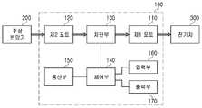
- the electric vehicle charging device 100includes a first port 110, a second port 120, a blocking unit 130, a control unit 140, and a communication unit 150. It may include at least some of the input unit 160 and the output unit 170.
- the first port 110may be configured to supply power to the electric vehicle 300.
- the second port 120may be configured to receive the power converted by the transformer 200 connected to the distribution line.
- the first and second ports 110 and 120may have a structure connected to a power cable to supply power in a wired manner, or may be implemented as a coil to supply power in a short distance in a wireless manner. .
- the blocking unit 130may switch an open / closed state between the first port 110 and the second port 120. Whether the electric vehicle 300 is charged by the electric vehicle charging device 100 may be determined according to switching of the open / closed state of the blocking unit 130.
- the controller 140receives the load information of the transformer 200 linked to the power distribution line, and when the load corresponding to the load information is greater than the reference load, the controller 140 is disposed between the first port 110 and the second port 120.
- the blocking unit 130may be controlled to be electrically opened. Accordingly, the lifespan of the transformer 200 linked to the distribution line can be extended, the damage frequency of the transformer can be reduced, and the power supplied from the transformer to the electric vehicle charging device 100 can be stabilized.
- the communicator 150receives load information from a data intensive processing device or an intelligent distribution box that processes data of a transformer 200 linked to a distribution line, and when charging is greater than a reference load, information about the non-charging information It may generate and transmit the non-charging information to the server. Accordingly, the manager can manage a plurality of electric vehicle charging devices integrally.
- the input unit 160may receive charging request information from the electric vehicle 300 or the driver.
- the charging request informationmay include charging method information, charging mode information, and / or charging capacity information.
- the charging method informationmay include power voltage information, frequency information, DC / AC information, wired / wireless information, and / or charging speed information
- the charging modemay include a quick mode, a medium speed mode, and a slow mode. It may include.
- the charging request informationmay be transferred to the controller 140. Thereafter, the controller 140 may control the switching time of the blocking unit 130 based on the charge request information, and may determine whether the power supply voltage, frequency, DC / AC, wired / wireless, and / or charging speeds are used. In this case, the fee information may be generated accordingly.
- the output unit 170may output charging state information of the electric vehicle 300, may output the charge information, and may output information input by the input unit 160 for the driver's input convenience.
- the output unit 170may output the charging non-execution information generated by the controller 140 when the load corresponding to the load information of the transformer 200 linked to the distribution line is greater than the reference load.
- the output unit 170may be implemented as a human-machine interface (HMI) such as a touch screen and a keypad together with the input unit 160.
- HMIhuman-machine interface
- FIG. 3is a block diagram specifically illustrating an electric vehicle charging device installed in an electric pole according to an embodiment of the present invention.
- the apparatus for charging an electric vehicleincludes a charger AC terminal 1001, an earth leakage breaker 1002, a first electricity meter 1003, a second electricity meter 1004, a first electricity meter communication terminal box 1005, and a second electricity meter Communication terminal box 1006, first current sensor 1007, second current sensor 1008, first magnet contactor 1009, second magnet contactor 1010, charging connector 1011, charging outlet 1012 ), Noise filter 1013, power supply 1014, controller 1015, card reader 1016, display unit 1017, speaker 1018, lighting device 1019, emergency switch 1020, door At least some of the solenoid 1021, the plug sensor 1022, and the retractor 1023 may be included.
- the charger AC terminal 1001may electrically connect the electric vehicle charging device and the intelligent distribution box, and may correspond to the second port illustrated in FIG. 2.
- the earth leakage breaker 1002may stop charging when an earth leakage occurs in the EV charging apparatus, and may correspond to the breaker illustrated in FIG. 2.
- the first power meter 1003may measure the amount of power of the charging power during charging according to the first mode.
- the first modemay be a slow mode.
- the second power meter 1004may measure the amount of power of the charging power at the time of charging according to the second mode.
- the second modemay be a rapid mode.
- the metering results of the first and second electricity meters 1003 and 1004may be used to generate charge information.
- the first power meter communication terminal box 1005may transmit the measurement result of the first power meter 1003 to the controller 1015 or the outside.
- the second electricity meter communication terminal box 1006may transmit the measurement result of the second electricity meter 1004 to the controller 1015 or the outside.
- the first current sensor 1007may measure the current of the power supplied to the electric vehicle according to the first mode.
- the second current sensor 1008may measure the current of the power supplied to the electric vehicle according to the second mode.
- the current value measured by the first or second current sensors 1007 and 1008may be used to control the leakage breaker 1002 by the controller 1015.
- the first magnet connector 1009may control the charging amount according to the first mode through on / off switching.
- the second magnet contactor 1010may control the charging amount according to the second mode through on / off switching.
- the charging connector 1011may have a structure electrically connected to the electric vehicle for the first mode charging, and may correspond to the first port illustrated in FIG. 2.
- the charging outlet 1012may have a structure electrically connected to the electric vehicle for the second mode charging, and may correspond to the first port illustrated in FIG. 2.
- the noise filter 1013may filter noise of the charging power source.
- the power supply 1014may supply operating power to the controller 1015, and may convert AC power into DC power.
- the power supply 1014may be implemented as a switched mode power supply (SMPS).
- SMPSswitched mode power supply
- the controller 1015may operate in the same manner as the controller illustrated in FIG. 2.
- the card reader 1016may receive payment information from an electric vehicle or a driver.
- the payment informationmay correspond to at least one of various payment methods such as a credit card, a check card, and a mobile payment.
- the display unit 1017may visually display information output by the output unit illustrated in FIG. 2.
- the speaker 1018may acoustically generate information output by the output unit illustrated in FIG. 2.
- the lighting device 1019may output a light source toward the charging connector 1011 and the charging outlet 1012 for driver convenience.
- the emergency switch 1020may stop charging according to an input from an electric vehicle or a driver.
- the door solenoid 1021may perform a locking function of the charging connector 1011 storage box.
- the plug sensor 1022may monitor whether the charging connector 1011 is disposed at a predetermined position.
- the retractor 1023may wind a charging cable connected to the charging connector 1011 on the reel. Accordingly, it is possible to prevent the charging cable from being dragged to the floor and damaged.
- the intelligent distribution boxincludes a distribution panel AC terminal 1024, a third power meter 1025, an AC input breaker 1026, a surge protector 1027, a distribution panel power supply device 1028, and a distribution panel control board 1029. ), An image processing apparatus 1030, a sign controller 1031, a wireless modem 1032, and a ground ground 1033. Since the intelligent distribution box may be integrated with the electric vehicle charging device, a configuration included in the intelligent distribution box may be included in the electric vehicle charging device.
- the distribution panel AC terminal 1024may electrically connect the intelligent distribution box and the distribution line.
- the third electricity meter 1025may measure the amount of power of the power passing through the intelligent distribution box.
- the AC input breaker 1026may cut off power supplied to the electric vehicle charging device in the intelligent distribution box.
- the surge protector 1027may protect the power supply from a surge.
- the distribution board power supply 1028may supply operating power of the distribution board control board 1029 and convert AC power into DC power.
- the distribution panel power supply 1028may be implemented as a switched mode power supply (SMPS).
- SMPSswitched mode power supply
- the distribution panel control board 1029may control the overall operation of the intelligent distribution panel.
- the image processing apparatus 1030may control the imaging apparatus of FIG. 1.
- the sign controller 1031may control the charging station display panel of FIG. 1.
- the wireless modem 1032may operate in the same manner as the communication unit of FIG. 2.
- the ground ground 1033may provide a ground voltage to the intelligent distribution board.
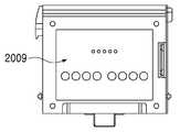
- 4A to 4Dare diagrams illustrating the structure of the intelligent switchboard shown in FIGS. 1 and 3.
- FIG. 4Ashows the front of the intelligent switchgear
- FIG. 4Bshows the back of the intelligent switchgear
- FIG. 4Cshows the side of the intelligent switchgear
- FIG. 4Dshows the bottom of the intelligent switchgear.
- the intelligent switchboardincludes a wiring switch 2001, a power meter 2002, a surge protector 2003, a power supply device 2004, a controller 2005, an image processing device 2006, and a wireless device. At least some of the modem 2007, the E-type modem 2008, the distribution panel AC terminal 2009, and the enclosure 2010 may be included.
- the enclosure 2010may have a structure attached to or detached from the pole, and may accommodate a breaker or the like.
- the configuration shown in Figure 4a to 4dmay be included in the electric vehicle charging device.
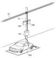
- FIG. 5is a diagram illustrating a converter arrangement of an electric vehicle charging system according to an embodiment of the present invention.
- the converter 250 for converting the power converted by the transformer connected to the distribution line 20 into the power for chargingmay be separated from the electric vehicle charging device 100 and installed in the electric pole 10. .
- the converter 250may have a relatively large weight or volume compared to the electric vehicle charging device 100. Therefore, the electric vehicle charging device 100 in which the converter 250 is separated may be miniaturized, and even when installed in the electric pole 10, the durability of the electric vehicle charging device that can withstand wind pressure or external shock may be secured.
- the electric vehicle charging device 100 having improved durabilitymay be easily installed for electric poles of various types or ages. Therefore, the electric vehicle charging system and the electric vehicle charging device 100 according to an embodiment of the present invention may provide an environment that can be easily installed on electric poles, thereby contributing to the spread of the electric vehicle charging infrastructure.
- the converter 250may be installed at a position higher than that at which the electric vehicle charging device 100 is installed in the electric pole 10. Accordingly, the electric pole 10 can stably grasp the center of gravity despite the electric vehicle charging device 100 and the converter 250 is installed.
- two or more converters 250may be implemented to stably support various charging modes.
- the EV charging apparatus 100may stably use various charging modes, and may distribute an increasing weight or volume of the converter 250.
- the converter 250converts the power converted by the transformer into a slow charging power and supplies the slow charging power to the electric vehicle charging device 100, and the power converted by the transformer. It may include a second converter for converting into a fast charging power supply and supplying the fast charging power to the electric vehicle charging device (100).
- the converter 250may be stably installed in the electric pole 10 while stably supporting various charging modes in the electric vehicle charging device 100.
- FIG. 6is a diagram illustrating a converter arrangement of an electric vehicle charging system according to an embodiment of the present invention.
- the transformer 200 and the converter 250a connected to the distribution linemay be installed on the second pole 12.
- the converter 250amay be installed on the second pole 12 that is different from the first pole 11 on which the electric vehicle charging device 100a is installed. Accordingly, the converter 250a may be installed at a lower position in the second pole 12 or in contact with the ground, and thus may have a stable structure.
- Power converted by the transformer 200 linked to the distribution linemay be supplied to the converter 250a through the second power cable 192.
- the charging power converted by the converter 250ais supplied to the electric vehicle charging device 100a through the distribution line 20 and the first power cable 191 or the electric vehicle charging device 100a through the underground cable (not shown). Can be supplied.
- FIG. 7is a diagram illustrating a converter arrangement of an electric vehicle charging system according to an embodiment of the present invention.
- the converter 250bmay be spaced apart from the first pole 11 and the second pole 12. Accordingly, the converter 250b may have a structure that is easy to expand.
- the converter 250bmay be electrically connected to the first underground cable 193 and the second underground cable 194 and installed in the ground. Accordingly, the converter 250b may prevent damage caused by external shocks in advance.
- the first underground cable 193may be electrically connected to the electric vehicle charging device 100b
- the second underground cable 194may be electrically connected to the transformer 200 linked to the distribution line. That is, the electric vehicle charging device according to an embodiment of the present invention can be supplied with power through the ground as well as the distribution line connected to the pole.
- FIG. 8is a flowchart illustrating a method for controlling an electric vehicle charging device installed in an electric pole according to an embodiment of the present invention.
- the methodmay further include receiving the load information from a data intensive processing device that generates load information by processing data of a transformer connected to a distribution line ( S110, comparing the load amount corresponding to the load information with a reference load amount (S120), and controlling the activation of the electric vehicle charging device powered by the transformer according to the load comparison result (S130).
- the methodmay further include transmitting or outputting charging non-execution information (S140), by the electric vehicle charging device or the electric vehicle charging system described above with reference to FIGS. 1 to 7. Can be performed.
- the method for controlling an electric vehicle charging devicemay be implemented by a computing environment including a processor, a memory, a storage, an input device, an output device, and a communication connection.
- the processor and the memorymay correspond to the above-described control unit
- the input devicemay correspond to the above-described input unit
- the output devicemay correspond to the above-described output unit
- the communication connectionis It may correspond to the above-described communication unit.
- ' ⁇ part' used in the present embodimentrefers to software or a hardware component such as a field-programmable gate array (FPGA) or an ASIC, and ' ⁇ part' performs certain roles.
- ' ⁇ 'is not meant to be limited to software or hardware.
- ' ⁇ Portion'may be configured to be in an addressable storage medium or may be configured to play one or more processors.
- ' ⁇ 'means components such as software components, object-oriented software components, class components, and task components, and processes, functions, properties, procedures, and the like. Subroutines, segments of program code, drivers, firmware, microcode, circuits, data, databases, data structures, tables, arrays, and variables.
- the functionality provided within the components and the 'parts'may be combined into a smaller number of components and the 'parts' or further separated into additional components and the 'parts'.
- the components and 'units'may be implemented to reproduce one or more CPUs in a device or system.
Landscapes
- Engineering & Computer Science (AREA)
- Power Engineering (AREA)
- Transportation (AREA)
- Mechanical Engineering (AREA)
- Life Sciences & Earth Sciences (AREA)
- Sustainable Development (AREA)
- Sustainable Energy (AREA)
- Charge And Discharge Circuits For Batteries Or The Like (AREA)
- Electric Propulsion And Braking For Vehicles (AREA)
Abstract
Description
Translated fromKorean본 발명은 배전선로에 연계된 변압기의 부하량에 기초한 전주에 설치된 전기차 충전 장치, 전기차 충전 시스템 및 전주에 설치된 전기차 충전 장치 제어 방법에 관한 것이다.The present invention relates to an electric vehicle charging device installed in a telephone pole, an electric vehicle charging system and an electric vehicle charging apparatus installed in a telephone pole based on a load of a transformer connected to a distribution line.
최근에는 화석 연료의 고갈문제와 화석 연료의 과다 사용으로 인한 대기 환경 오염 문제의 심각화에 따라 재생 가능한 신재생 에너지의 사용과, 친환경적인 운송 수단에 대한 연구와 개발이 전세계적으로 활발하게 이루어지고 있다. 이러한 친환경적인 운송 수단으로서 전기차(Electric Vehicle, EV)가 주목받고 있다. 전기차 충전 인프라 확산은 전기차가 널리 보급되기 위해서 필수적이다.Recently, due to the problem of depletion of fossil fuels and air pollution due to excessive use of fossil fuels, research and development of renewable energy and eco-friendly transportation methods are actively conducted worldwide. . Electric vehicles (EVs) are attracting attention as such environmentally friendly means of transportation. The proliferation of EV charging infrastructure is essential for the spread of EVs.
본 발명은 배전선로에 연계된 변압기에 의해 변환된 전원을 전기차 충전에 안전하게 이용할 수 있는 환경을 제공하여 전기차 충전 인프라 확산에 일조할 수 있는 전주에 설치된 전기차 충전 장치, 전기차 충전 시스템 및 전주에 설치된 전기차 충전 장치 제어 방법을 제공한다.The present invention provides an environment that can safely use the power converted by the transformer connected to the distribution line for electric vehicle charging, electric vehicle charging device installed in Jeonju, electric car charging system and electric vehicle installed in Jeonju that can help spread the EV charging infrastructure Provided is a charging device control method.
본 발명의 일 실시 예에 따른 전주에 설치된 전기차 충전 장치는, 전기차에 전원을 공급하도록 구성된 제1 포트; 배전선로에 연계된 변압기에 의해 변환된 전원을 공급받도록 구성된 제2 포트; 상기 제1 포트와 상기 제2 포트의 사이의 개폐상태를 스위칭하는 차단부; 및 상기 변압기의 부하량 정보를 전달받고 상기 부하량 정보에 대응되는 부하량이 기준 부하량보다 클 경우에 상기 제1 포트와 상기 제2 포트의 사이가 전기적으로 개방되도록 상기 차단부를 제어하는 제어부; 를 포함할 수 있다.An electric vehicle charging device installed in an electric pole according to an embodiment of the present invention includes a first port configured to supply power to an electric vehicle; A second port configured to receive power converted by a transformer associated with the distribution line; A blocking unit for switching an open / closed state between the first port and the second port; And a controller configured to control the blocking unit to electrically open the first port and the second port when the load information of the transformer is received and the load corresponding to the load information is greater than a reference load. It may include.
예를 들어 상기 전주에 설치된 전기차 충전 장치는, 상기 변압기의 데이터를 처리하는 데이터 집중처리 장치 또는 지능형 분전함으로부터 상기 부하량 정보를 수신하고, 상기 부하량 정보에 대응되는 부하량이 기준 부하량보다 클 경우에 충전 미시행 정보를 서버로 송신하는 통신부를 더 포함할 수 있다.For example, the electric vehicle charging device installed in the electric pole receives the load information from a data intensive processor or an intelligent distribution box that processes the data of the transformer, and does not charge when the load corresponding to the load information is greater than a reference load. The apparatus may further include a communication unit configured to transmit the information to the server.
예를 들어 상기 전주에 설치된 전기차 충전 장치는, 충전 요청 정보를 입력 받는 입력부; 및 상기 부하량 정보에 대응되는 부하량이 기준 부하량보다 클 경우에 충전 미시행 정보를 출력하는 출력부; 를 더 포함할 수 있다.For example, the electric vehicle charging device installed in the electric pole, the input unit for receiving the charge request information; And an output unit configured to output charging non-execution information when the load corresponding to the load information is greater than a reference load. It may further include.
예를 들어 상기 전주에 설치된 전기차 충전 장치는, 상기 차단부를 수용하고 전주에 설치되도록 구성된 외함을 더 포함할 수 있다.For example, the electric vehicle charging device installed on the pole may further include an enclosure configured to receive the blocking unit and be installed on the pole.
예를 들어 상기 전주에 설치된 전기차 충전 장치는, 상기 제2 포트와 상기 배전선로를 전기적으로 연결하는 전원케이블을 더 포함할 수 있다.For example, the electric vehicle charging device installed in the electric pole, may further include a power cable for electrically connecting the second port and the distribution line.
본 발명의 일 실시 예에 따른 전기차 충전 시스템은, 배전선로에 연계되고 제1 전주에 설치된 변압기; 상기 변압기의 데이터를 처리하여 부하량 정보를 생성하는 데이터 집중처리 장치; 상기 제1 전주 또는 제2 전주에 설치되고 상기 변압기로부터 전원을 공급받고 전기차를 충전하도록 구성된 충전 장치; 및 상기 부하량 정보를 전달받고 상기 부하량 정보에 대응되는 부하량이 기준 부하량보다 클 경우에 상기 충전 장치를 비활성화시키는 지능형 분전함; 을 포함할 수 있다.Electric vehicle charging system according to an embodiment of the present invention, the transformer is connected to the distribution line and installed on the first pole; A data intensive processor for processing data of the transformer to generate load information; A charging device installed on the first pole or the second pole and configured to receive power from the transformer and charge the electric vehicle; And an intelligent distribution box configured to deactivate the charging device when the load information is received and the load corresponding to the load information is greater than a reference load. It may include.
본 발명의 일 실시 예에 따른 전기차 충전 장치 제어 방법은, 배전선로에 연계된 변압기의 데이터를 처리하여 부하량 정보를 생성하는 데이터 집중처리 장치로부터 상기 부하량 정보를 전달받는 단계; 상기 부하량 정보에 대응되는 부하량과 기준 부하량을 비교하는 단계; 및 상기 변압기로부터 전원을 공급받는 전기차 충전 장치의 활성화 여부를 부하량 비교 결과에 따라 제어하는 단계; 를 포함할 수 있다.An electric vehicle charging device control method according to an embodiment of the present invention, the step of receiving the load information from the data central processing unit for generating the load information by processing the data of the transformer associated with the distribution line; Comparing a load amount corresponding to the load amount information with a reference load amount; And controlling whether the electric vehicle charging device powered by the transformer is activated according to a load comparison result. It may include.
본 발명의 일 실시 예에 따른 배전선로에 연계된 변압기의 부하량에 기초한 전주에 설치된 전기차 충전 장치, 전기차 충전 시스템 및 전주에 설치된 전기차 충전 장치 제어 방법은, 배전선로에 연계된 변압기가 전기차 충전에 추가적으로 사용됨에도 불구하고 배전선로에 연계된 변압기의 수명 감축 및 손상을 예방할 수 있으며, 배전선로에 연계된 변압기로부터 안정적으로 전원을 공급받아서 전기차를 충전할 수 있다.The electric vehicle charging device, electric vehicle charging system and electric vehicle charging device installed on the pole based on the load of the transformer associated with the distribution line according to an embodiment of the present invention, the transformer associated with the distribution line in addition to the electric vehicle charging Although used, it is possible to prevent the reduction of life and damage of the transformer connected to the distribution line, and to charge the electric vehicle by receiving the power stably from the transformer connected to the distribution line.
이에 따라, 배전선로에 연계된 변압기에 의해 변환된 전원을 전기차 충전에 안전하게 이용할 수 있는 환경이 조성될 수 있으며, 전기차 충전 인프라는 널리 확산될 수 있다.Accordingly, an environment in which the power converted by the transformer connected to the distribution line can be safely used for charging the electric vehicle can be created, and the electric vehicle charging infrastructure can be widely spread.
도 1은 본 발명의 일 실시 예에 따른 전기차 충전 시스템을 나타낸 도면이다.1 is a view showing an electric vehicle charging system according to an embodiment of the present invention.
도 2는 본 발명의 일 실시 예에 따른 전주에 설치된 전기차 충전 장치를 나타낸 블록도이다.2 is a block diagram showing an electric vehicle charging device installed in a pole according to an embodiment of the present invention.
도 3은 본 발명의 일 실시 예에 따른 전주에 설치된 전기차 충전 장치를 구체적으로 예시한 블록도이다.3 is a block diagram specifically illustrating an electric vehicle charging device installed in an electric pole according to an embodiment of the present invention.
도 4a 내지 도 4d는 도 1 및 도 3에 도시된 지능형 분전함의 구조를 예시한 도면이다.4A to 4D illustrate the structure of the intelligent distribution box shown in FIGS. 1 and 3.
도 5는 본 발명의 일 실시 예에 따른 전기차 충전 시스템의 컨버터 배치를 예시한 도면이다.5 is a diagram illustrating a converter arrangement of an electric vehicle charging system according to an embodiment of the present invention.
도 6은 본 발명의 일 실시 예에 따른 전기차 충전 시스템의 컨버터 배치를 예시한 도면이다.6 is a diagram illustrating a converter arrangement of an electric vehicle charging system according to an embodiment of the present invention.
도 7은 본 발명의 일 실시 예에 따른 전기차 충전 시스템의 컨버터 배치를 예시한 도면이다.7 is a diagram illustrating a converter arrangement of an electric vehicle charging system according to an embodiment of the present invention.
도 8은 본 발명의 일 실시 예에 따른 전주에 설치된 전기차 충전 장치 제어 방법을 나타낸 순서도이다.8 is a flowchart illustrating a method for controlling an electric vehicle charging device installed in an electric pole according to an embodiment of the present invention.
후술하는 본 발명에 대한 상세한 설명은, 본 발명이 실시될 수 있는 특정 실시예를 예시로서 도시하는 첨부 도면을 참조한다. 본 발명의 다양한 실시예는 서로 다르지만 상호 배타적일 필요는 없음이 이해되어야 한다. 예를 들어, 여기에 기재되어 있는 특정 형상, 구조 및 특성은 일 실시예에 관련하여 본 발명의 정신 및 범위를 벗어나지 않으면서 다른 실시예로 구현될 수 있다. 또한, 각각의 개시된 실시예 내의 개별 구성요소의 위치 또는 배치는 본 발명의 정신 및 범위를 벗어나지 않으면서 변경될 수 있음이 이해되어야 한다. 따라서, 후술하는 상세한 설명은 한정적인 의미로서 취하려는 것이 아니며, 본 발명의 범위는, 적절하게 설명된다면, 그 청구항들이 주장하는 것과 균등한 모든 범위와 더불어 첨부된 청구항에 의해서만 한정된다. 도면에서 유사한 참조부호는 여러 측면에 걸쳐서 동일하거나 유사한 기능을 지칭한다.DETAILED DESCRIPTION The following detailed description of the invention refers to the accompanying drawings that show, by way of illustration, specific embodiments in which the invention may be practiced. It should be understood that the various embodiments of the present invention are different but need not be mutually exclusive. For example, certain shapes, structures, and characteristics described herein may be embodied in other embodiments without departing from the spirit and scope of the invention with respect to one embodiment. In addition, it is to be understood that the location or arrangement of individual components within each disclosed embodiment may be changed without departing from the spirit and scope of the invention. The following detailed description, therefore, is not to be taken in a limiting sense, and the scope of the present invention, if properly described, is defined only by the appended claims, along with the full range of equivalents to which such claims are entitled. Like reference numerals in the drawings refer to the same or similar functions throughout the several aspects.
이하에서는, 본 발명이 속하는 기술분야에서 통상의 지식을 가진 자가 본 발명을 용이하게 실시할 수 있도록 하기 위하여, 본 발명의 실시 예들에 관하여 첨부된 도면을 참조하여 상세히 설명하기로 한다.DETAILED DESCRIPTION Hereinafter, exemplary embodiments of the present invention will be described in detail with reference to the accompanying drawings so that those skilled in the art may easily implement the present invention.
도 1은 본 발명의 일 실시 예에 따른 전기차 충전 시스템을 나타낸 도면이다.1 is a view showing an electric vehicle charging system according to an embodiment of the present invention.
도 1을 참조하면, 본 발명의 일 실시 예에 따른 전기차 충전 시스템은, 전기차 충전 장치(100), 지능형 분전함(180), 데이터 집중처리 장치(210), 변압기(미도시)를 포함할 수 있으며, 전주(10), 배전선로(20), 주차공간(30), 차량충돌 방지용 볼라드(40), 차량 스토퍼(50), 충전소 표시판(60), 영상 장치(70)를 포함하는 전기차 충전소에 구비될 수 있다. 여기서, 전주(10)는 전신주로 한정되지 않으며, 전기차 충전 장치(100)가 매달릴 수 있고 전기에너지를 배전선로로부터 공급받아서 전기차 충전 장치(100)로 전달하는 환경을 제공할 수 있는 기둥을 의미한다.Referring to FIG. 1, an electric vehicle charging system according to an embodiment of the present disclosure may include an electric
전기차 충전 장치(100)는 전주(10)에 설치되고 변압기로부터 전원을 공급받고 전기차(300)를 충전하도록 구성될 수 있다. 예를 들어, 상기 전기차 충전 장치(100)는 전원케이블(190)을 통해 배전선로(20)에 전기적으로 연결됨으로써 공급받을 수 있다.The electric
여기서, 변압기는 배전선로(20)에 연계되어 고압의 전력을 저압의 전원으로 변환할 수 있다. 예를 들어, 상기 변압기는 전주(10) 또는 제2 전주(미도시) 상에 설치된 주상변압기로 구현될 수 있고, 도로나 인도 주위에 설치된 지상변압기로 구현될 수도 있다.Here, the transformer may be connected to the
데이터 집중처리 장치(210)는 상기 변압기의 전류, 전압 또는 전력 데이터를 수집하고 처리하여 부하량 정보를 생성할 수 있다. 여기서, 상기 부하량 정보는 상기 변압기에 의해 변환되는 총 전력량으로 정의될 수 있다. 상기 변압기의 부하량이 클 경우, 상기 변압기의 수명은 감소할 수 있으며, 상기 변압기의 손상 빈도는 높아질 수 있으며, 상기 변압기로부터 전기차 충전 장치(100)로 공급되는 전원은 불안정할 수 있다.The data
지능형 분전함(180)은 상기 부하량 정보를 전달받고 상기 부하량 정보에 대응되는 부하량이 기준 부하량보다 클 경우에 전기차 충전 장치(100)를 비활성화시킬 수 있다. 비활성화된 전기차 충전 장치(100)는 일시적으로 충전을 중단할 수 있다.The
이에 따라, 상기 변압기의 수명은 연장될 수 있으며, 상기 변압기의 손상 빈도는 감소할 수 있으며, 상기 변압기로부터 전기차 충전 장치(100)로 공급되는 전원은 안정화될 수 있다.Accordingly, the life of the transformer can be extended, the damage frequency of the transformer can be reduced, and the power supplied from the transformer to the electric
한편 설계에 따라, 상기 지능형 분전함(180)과 전기차 충전 장치(100)는 일체화될 수 있다. 즉, 전기차 충전 시스템이 지능형 분전함(180)을 포함하지 않을 경우, 상기 전기차 충전 장치(100)는 지능형 분전함(180)의 역할을 대신 수행할 수도 있다.Meanwhile, according to the design, the
한편, 상기 변압기에 의해 변환된 전원은 도 5 내지 도 7을 참조하여 설명하는 컨버터에 의해 전기차(300)로 공급되기 전에 적어도 한번 더 변환될 수 있다. 설계에 따라, 상기 컨버터는 전기차 충전 장치(100)에 포함될 수 있고, 도 5 내지 도 7에 도시된 바와 같이 전기차 충전 장치(100)로부터 분리될 수 있다.Meanwhile, the power converted by the transformer may be converted at least once more before being supplied to the
도 2는 본 발명의 일 실시 예에 따른 전주에 설치된 전기차 충전 장치를 나타낸 블록도이다.2 is a block diagram showing an electric vehicle charging device installed in a pole according to an embodiment of the present invention.
도 2를 참조하면, 본 발명의 일 실시 예에 따른 전기차 충전 장치(100)는 제1 포트(110), 제2 포트(120), 차단부(130), 제어부(140), 통신부(150), 입력부(160), 출력부(170) 중 적어도 일부를 포함할 수 있다.2, the electric
제1 포트(110)는 전기차(300)에 전원을 공급하도록 구성될 수 있다.The
제2 포트(120)는 배전선로에 연계된 변압기(200)에 의해 변환된 전원을 공급받도록 구성될 수 있다.The
예를 들어, 상기 제1 및 제2 포트(110, 120)는 유선 방식으로 전원을 공급하도록 전원케이블에 연결되는 구조를 가질 수 있으며, 무선 방식으로 근거리에서 전원을 공급하도록 코일로 구현될 수도 있다.For example, the first and
차단부(130)는 제1 포트(110)와 제2 포트(120)의 사이의 개폐상태를 스위칭할 수 있다. 전기차 충전 장치(100)의 전기차(300)에 대한 충전 여부는 상기 차단부(130)의 개폐상태 스위칭에 따라 결정될 수 있다.The
제어부(140)는 배전선로에 연계된 변압기(200)의 부하량 정보를 전달받고 상기 부하량 정보에 대응되는 부하량이 기준 부하량보다 클 경우에 제1 포트(110)와 제2 포트(120)의 사이가 전기적으로 개방되도록 차단부(130)를 제어할 수 있다. 이에 따라, 배전선로에 연계된 변압기(200)의 수명은 연장될 수 있으며, 상기 변압기의 손상 빈도는 감소할 수 있으며, 상기 변압기로부터 전기차 충전 장치(100)로 공급되는 전원은 안정화될 수 있다.The
통신부(150)는 배전선로에 연계된 변압기(200)의 데이터를 처리하는 데이터 집중처리 장치 또는 지능형 분전함으로부터 부하량 정보를 수신하고, 상기 부하량 정보에 대응되는 부하량이 기준 부하량보다 클 경우에 충전 미시행 정보를 생성할 수 있으며, 상기 충전 미시행 정보를 서버로 송신할 수 있다. 이에 따라, 관리자는 다수의 전기차 충전 장치를 통합적으로 관리할 수 있다.The
입력부(160)는 전기차(300) 또는 운전자로부터 충전 요청 정보를 입력 받을 수 있다. 상기 충전 요청 정보는 충전 방식 정보, 충전 모드 정보 및/또는 충전 용량 정보를 포함할 수 있다. 여기서, 충전 방식 정보는 전원 전압 정보, 주파수 정보, 직류/교류 여부 정보, 유선방식/무선방식 여부 정보 및/또는 충전 속도 정보를 포함할 수 있으며, 충전 모드는 급속 모드, 중속 모드, 완속 모드를 포함할 수 있다. 상기 충전 요청 정보는 제어부(140)로 전달될 수 있다. 이후, 제어부(140)는 상기 충전 요청 정보에 기초하여 차단부(130)의 스위칭 시점을 제어할 수 있으며, 전원 전압, 주파수, 직류/교류 여부, 유선방식/무선방식 여부 및/또는 충전 속도를 결정할 수 있으며, 이에 따른 요금 정보를 생성할 수 있다.The
출력부(170)는 전기차(300) 충전 상황 정보를 출력할 수 있으며, 상기 요금 정보를 출력할 수 있으며, 운전자의 입력 편의를 위해 입력부(160)에 의해 입력된 정보를 출력할 수 있다.The
또한, 상기 출력부(170)는 배전선로에 연계된 변압기(200)의 부하량 정보에 대응되는 부하량이 기준 부하량보다 클 경우에 제어부(140)에 의해 생성된 충전 미시행 정보를 출력할 수 있다.In addition, the
한편, 상기 출력부(170)는 입력부(160)와 함께 터치스크린, 키패드와 같은 HMI(Human-Machine Interface)로 구현될 수 있다.The
도 3은 본 발명의 일 실시 예에 따른 전주에 설치된 전기차 충전 장치를 구체적으로 예시한 블록도이다.3 is a block diagram specifically illustrating an electric vehicle charging device installed in an electric pole according to an embodiment of the present invention.
도 3을 참조하면, 전기차 충전 장치는, 충전기 AC 터미널(1001), 누전 차단기(1002), 제1 전력량계(1003), 제2 전력량계(1004), 제1 전력량계 통신단자함(1005), 제2 전력량계 통신단자함(1006), 제1 전류센서(1007), 제2 전류센서(1008), 제1 마그네트 콘텍터(1009), 제2 마그네트 콘텍터(1010), 충전 커넥터(1011), 충전 콘센트(1012), 노이즈 필터(1013), 전원공급장치(1014), 컨트롤러(1015), 카드 리더기(1016), 디스플레이부(1017), 스피커(1018), 조명 장치(1019), 비상 스위치(1020), 도어 솔레노이드(1021), 플러그 센서(1022), 리트렉터(1023) 중 적어도 일부를 포함할 수 있다.Referring to FIG. 3, the apparatus for charging an electric vehicle includes a
충전기 AC 터미널(1001)은 전기차 충전 장치와 지능형 분전함을 전기적으로 연결시킬 수 있으며, 도 2에 도시된 제2 포트에 대응될 수 있다.The
누전 차단기(1002)는 전기차 충전 장치에서 누전이 발생한 경우에 충전을 중단할 수 있으며, 도 2에 도시된 차단부에 대응될 수 있다.The
제1 전력량계(1003)는 제1 모드에 따른 충전시에 충전 전원의 전력량을 계량할 수 있다. 예를 들어, 상기 제1 모드는 완속 모드일 수 있다.The
제2 전력량계(1004)는 제2 모드에 따른 충전시에 충전 전원의 전력량을 계량할 수 있다. 예를 들어, 상기 제2 모드는 급속 모드일 수 있다.The
제1 및 제2 전력량계(1003, 1004)의 계량 결과는 요금 정보 생성에 이용될 수 있다.The metering results of the first and
제1 전력량계 통신단자함(1005)은 제1 전력량계(1003)의 계량 결과를 컨트롤러(1015) 또는 외부로 송신할 수 있다.The first power meter
제2 전력량계 통신단자함(1006)은 제2 전력량계(1004)의 계량 결과를 컨트롤러(1015) 또는 외부로 송신할 수 있다.The second electricity meter
제1 전류센서(1007)는 제1 모드에 따라 전기차에 공급되는 전원의 전류를 측정할 수 있다.The first
제2 전류센서(1008)는 제2 모드에 따라 전기차에 공급되는 전원의 전류를 측정할 수 있다.The second
제1 또는 제2 전류센서(1007, 1008)에 의해 측정된 전류값은 컨트롤러(1015)에 의한 누전 차단기(1002)의 차단 제어에 활용될 수 있다.The current value measured by the first or second
제1 마그네트 콘텍터(1009)는 온/오프 스위칭을 통해 제1 모드에 따른 충전량을 제어할 수 있다.The
제2 마그네트 콘텍터(1010)는 온/오프 스위칭을 통해 제2 모드에 따른 충전량을 제어할 수 있다.The
충전 커넥터(1011)는 제1 모드 충전을 위해 전기차에 전기적으로 연결되는 구조를 가질 수 있으며, 도 2에 도시된 제1 포트에 대응될 수 있다.The charging
충전 콘센트(1012)는 제2 모드 충전을 위해 전기차에 전기적으로 연결되는 구조를 가질 수 있으며, 도 2에 도시된 제1 포트에 대응될 수 있다.The
노이즈 필터(1013)는 충전 전원의 노이즈를 필터링할 수 있다.The
전원공급장치(1014)는 컨트롤러(1015)에 동작 전원을 공급할 수 있으며, AC 전원을 DC 전원으로 변환할 수 있다. 예를 들어, 상기 전원공급장치(1014)는 스위칭모드 파워 서플라이(SMPS)로 구현될 수 있다.The
컨트롤러(1015)는 도 2에 도시된 제어부와 동일하게 동작할 수 있다.The
카드 리더기(1016)는 전기차 또는 운전자로부터 결제 정보를 입력 받을 수 있다. 예를 들어, 상기 결제 정보는 신용카드, 체크카드, 모바일 결제 등 다양한 결제방식 중 적어도 하나에 대응될 수 있다.The
디스플레이부(1017)는 도 2에 도시된 출력부가 출력하는 정보를 시각적으로 표시할 수 있다.The
스피커(1018)는 도 2에 도시된 출력부가 출력하는 정보를 청각적으로 생성할 수 있다.The
조명 장치(1019)는 운전자 편의를 위해 충전 커넥터(1011) 및 충전 콘센트(1012)를 향하는 광원을 출력할 수 있다.The
비상 스위치(1020)는 전기차 또는 운전자로부터의 입력에 따라 충전을 중단할 수 있다.The
도어 솔레노이드(1021)는 충전 커넥터(1011) 보관함의 잠금기능을 수행할 수 있다.The
플러그 센서(1022)는 충전 커넥터(1011)가 소정의 위치에 배치되어 있는지 감시할 수 있다.The
리트렉터(1023)는 충전 커넥터(1011)에 연결된 충전케이블을 릴에 감을 수 있다. 이에 따라, 충전케이블이 바닥에 끌려서 손상되는 것은 예방될 수 있다.The
도 3을 참조하면, 지능형 분전함은, 분전반 AC 터미널(1024), 제3 전력량계(1025), AC 입력 차단기(1026), 서지보호기(1027), 분전반 전원공급장치(1028), 분전반 제어보드(1029), 영상처리장치(1030), 표지판 제어기(1031), 무선 모뎀(1032), 대지 접지(1033) 중 적어도 일부를 포함할 수 있다. 상기 지능형 분전함은 상기 전기차 충전 장치와 일체화될 수 있으므로, 상기 지능형 분전함이 포함하는 구성은 상기 전기차 충전 장치에 포함될 수도 있다.Referring to FIG. 3, the intelligent distribution box includes a distribution
분전반 AC 터미널(1024)은 지능형 분전함와 배전선로를 전기적으로 연결시킬 수 있다.The distribution
제3 전력량계(1025)는 지능형 분전함을 통과하는 전원의 전력량을 계량할 수 있다.The
AC 입력 차단기(1026)는 지능형 분전함에서 전기차 충전 장치로 공급되는 전원을 차단할 수 있다.The
서지보호기(1027)는 전원을 서지(surge)로부터 보호할 수 있다.The
분전반 전원공급장치(1028)는 분전반 제어보드(1029)의 동작 전원을 공급할 수 있으며, AC 전원을 DC 전원으로 변환할 수 있다. 예를 들어, 상기 분전반 전원공급장치(1028)는 스위칭모드 파워 서플라이(SMPS)로 구현될 수 있다.The distribution
분전반 제어보드(1029)는 지능형 분전반의 전반적인 동작을 제어할 수 있다.The distribution panel control board 1029 may control the overall operation of the intelligent distribution panel.
영상처리장치(1030)는 도 1의 영상 장치를 제어할 수 있다.The image processing apparatus 1030 may control the imaging apparatus of FIG. 1.
표지판 제어기(1031)는 도 1의 충전소 표시판을 제어할 수 있다.The
무선 모뎀(1032)은 도 2의 통신부와 동일하게 동작할 수 있다.The
대지 접지(1033)는 지능형 분전반에 접지 전압을 제공할 수 있다.The
도 4a 내지 도 4d는 도 1 및 도 3에 도시된 지능형 배전반의 구조를 예시한 도면이다.4A to 4D are diagrams illustrating the structure of the intelligent switchboard shown in FIGS. 1 and 3.
도 4a는 지능형 배전반의 앞면을 나타내며, 도 4b는 지능형 배전반의 뒷면을 나타내며, 도 4c는 지능형 배전반의 측면을 나타내며, 도 4d는 지능형 배전반의 하면을 나타낸다.4A shows the front of the intelligent switchgear, FIG. 4B shows the back of the intelligent switchgear, FIG. 4C shows the side of the intelligent switchgear, and FIG. 4D shows the bottom of the intelligent switchgear.
도 4a 내지 도 4d를 참조하면, 지능형 배전반은, 배선용 스위치(2001), 전력량계(2002), 서지보호기(2003), 전원공급장치(2004), 컨트롤러(2005), 영상처리장치(2006), 무선 모뎀(2007), E 타입 모뎀(2008), 분전반 AC 터미널(2009), 외함(2010) 중 적어도 일부를 포함할 수 있다.4A to 4D, the intelligent switchboard includes a
외함(2010)은 전주에 부착되거나 상기 전주로부터 탈착되는 구조를 가질 수 있으며, 차단기 등을 수용할 수 있다.The
한편, 상기 지능형 분전함은 본 발명의 일 실시 예에 따른 전기차 충전 장치와 일체화될 수 있으므로, 도 4a 내지 도 4d에 도시된 구성은 상기 전기차 충전 장치에 포함될 수 있다.On the other hand, since the intelligent distribution box can be integrated with the electric vehicle charging device according to an embodiment of the present invention, the configuration shown in Figure 4a to 4d may be included in the electric vehicle charging device.
도 5는 본 발명의 일 실시 예에 따른 전기차 충전 시스템의 컨버터 배치를 예시한 도면이다.5 is a diagram illustrating a converter arrangement of an electric vehicle charging system according to an embodiment of the present invention.
도 5를 참조하면, 배전선로(20)에 연계된 변압기의 의해 변환된 전원을 충전용 전원으로 변환하는 컨버터(250)는 전기차 충전 장치(100)로부터 분리되어 전주(10)에 설치될 수 있다.Referring to FIG. 5, the
통상적으로, 컨버터(250)는 전기차 충전 장치(100)에 비해 상대적으로 큰 무게 또는 부피를 가질 수 있다. 따라서, 컨버터(250)가 분리된 전기차 충전 장치(100)는 소형화될 수 있으며, 전주(10)에 설치되더라도 풍압이나 외부 충격에 견딜 수 있는 정도의 내구도를 확보할 수 있다.Typically, the
이처럼, 내구도가 향상된 전기차 충전 장치(100)는 다양한 종류 또는 나이의 전주에 대해 용이하게 설치될 수 있다. 따라서, 본 발명의 일 실시 예에 따른 전기차 충전 시스템 및 전기차 충전 장치(100)는 전주에 설치되기 용이한 환경을 제공하여 전기차 충전 인프라 확산에 일조할 수 있다.As such, the electric
예를 들어, 상기 컨버터(250)는 전주(10)에서 전기차 충전 장치(100)가 설치된 위치보다 높은 위치에 설치될 수 있다. 이에 따라, 전주(10)는 전기차 충전 장치(100)와 컨버터(250)가 설치됨에도 불구하고 안정적으로 무게중심을 잡을 수 있다.For example, the
한편, 상기 컨버터(250)는 다양한 충전 모드를 안정적으로 지원하기 위해 2개 이상으로 구현될 수도 있다. 상기 컨버터(250)가 2개 이상으로 구현될 경우, 전기차 충전 장치(100)는 다양한 충전 모드를 안정적으로 사용할 수 있으며, 상기 컨버터(250)의 증가하는 무게 또는 부피를 분산할 수 있다.Meanwhile, two or
예를 들어, 상기 컨버터(250)는 변압기의 의해 변환된 전원을 완속 충전용 전원으로 변환하고 상기 완속 충전용 전원을 전기차 충전 장치(100)로 공급하는 제1 컨버터와, 변압기의 의해 변환된 전원을 급속 충전용 전원으로 변환하고 상기 급속 충전용 전원을 전기차 충전 장치(100)로 공급하는 제2 컨버터를 포함할 수 있다.For example, the
이에 따라, 상기 컨버터(250)는 전기차 충전 장치(100)에 다양한 충전 모드를 안정적으로 지원하면서도 안정적으로 전주(10)에 설치될 수 있다.Accordingly, the
도 6은 본 발명의 일 실시 예에 따른 전기차 충전 시스템의 컨버터 배치를 예시한 도면이다.6 is a diagram illustrating a converter arrangement of an electric vehicle charging system according to an embodiment of the present invention.
도 6을 참조하면, 배전선로에 연계된 변압기(200)와 컨버터(250a)는 제2 전주(12)에 설치될 수 있다.Referring to FIG. 6, the
즉, 컨버터(250a)는 전기차 충전 장치(100a)가 설치된 제1 전주(11)와 다른 제2 전주(12)에 설치될 수 있다. 이에 따라, 컨버터(250a)는 제2 전주(12)에서 낮은 위치에 설치되거나 지상에 접하도록 설치될 수 있으므로, 안정적인 구조를 가질 수 있다.That is, the
배전선로에 연계된 변압기(200)에 의해 변환된 전원은 제2 전원케이블(192)를 통해 상기 컨버터(250a)로 공급될 수 있다.Power converted by the
상기 컨버터(250a)에 의해 변환된 충전용 전원은 배전선로(20) 및 제1 전원케이블(191)을 통해 전기차 충전 장치(100a)로 공급되거나 지중케이블(미도시)을 통해 전기차 충전 장치(100a)로 공급될 수 있다.The charging power converted by the
도 7은 본 발명의 일 실시 예에 따른 전기차 충전 시스템의 컨버터 배치를 예시한 도면이다.7 is a diagram illustrating a converter arrangement of an electric vehicle charging system according to an embodiment of the present invention.
도 7을 참조하면, 컨버터(250b)는 제1 전주(11)와 제2 전주(12)로부터 이격되어 설치될 수 있다. 이에 따라, 컨버터(250b)는 확장이 용이한 구조를 가질 수 있다.Referring to FIG. 7, the
또한, 상기 컨버터(250b)는 제1 지중케이블(193)과 제2 지중케이블(194)에 전기적으로 연결되고 지중에 설치될 수 있다. 이에 따라, 컨버터(250b)는 외부의 충격에 따른 손상을 미연에 방지할 수 있다.In addition, the
한편, 상기 제1 지중케이블(193)은 전기차 충전 장치(100b)에 전기적으로 연결될 수 있으며, 상기 제2 지중케이블(194)은 배전선로에 연계된 변압기(200)에 전기적으로 연결될 수 있다. 즉, 본 발명의 일 실시 예에 따른 전기차 충전 장치는 전주에 연결된 배전선로뿐만 아니라 지중을 통해서도 전원을 공급받을 수 있다.Meanwhile, the first
도 8은 본 발명의 일 실시 예에 따른 전주에 설치된 전기차 충전 장치 제어 방법을 나타낸 순서도이다.8 is a flowchart illustrating a method for controlling an electric vehicle charging device installed in an electric pole according to an embodiment of the present invention.
도 8을 참조하면, 본 발명의 일 실시 예에 따른 전기차 충전 장치 제어 방법은, 배전선로에 연계된 변압기의 데이터를 처리하여 부하량 정보를 생성하는 데이터 집중처리 장치로부터 상기 부하량 정보를 전달받는 단계(S110)와, 상기 부하량 정보에 대응되는 부하량과 기준 부하량을 비교하는 단계(S120)와, 상기 변압기로부터 전원을 공급받는 전기차 충전 장치의 활성화 여부를 부하량 비교 결과에 따라 제어하는 단계(S130)를 포함할 수 있으며, 상기 전기차 충전 장치가 비활성화될 경우에 충전 미시행 정보를 송신하거나 출력하는 단계(S140)를 더 포함할 수 있으며, 도 1 내지 도 7을 통해 전술한 전기차 충전 장치 또는 전기차 충전 시스템에 의해 수행될 수 있다.Referring to FIG. 8, in the method of controlling an electric vehicle charging apparatus according to an embodiment of the present disclosure, the method may further include receiving the load information from a data intensive processing device that generates load information by processing data of a transformer connected to a distribution line ( S110, comparing the load amount corresponding to the load information with a reference load amount (S120), and controlling the activation of the electric vehicle charging device powered by the transformer according to the load comparison result (S130). When the electric vehicle charging device is deactivated, the method may further include transmitting or outputting charging non-execution information (S140), by the electric vehicle charging device or the electric vehicle charging system described above with reference to FIGS. 1 to 7. Can be performed.
한편, 상기 전기차 충전 장치 제어 방법은 프로세서, 메모리, 스토리지, 입력 디바이스, 출력 디바이스 및 통신 접속을 포함하는 컴퓨팅 환경에 의해 구현될 수 있다. 예를 들어, 상기 프로세서 및 상기 메모리는 전술한 제어부에 대응될 수 있으며, 상기 입력 디바이스는 전술한 입력부에 대응될 수 있으며, 상기 출력 디바이스는 전술한 출력부에 대응될 수 있으며, 상기 통신 접속은 전술한 통신부에 대응될 수 있다.Meanwhile, the method for controlling an electric vehicle charging device may be implemented by a computing environment including a processor, a memory, a storage, an input device, an output device, and a communication connection. For example, the processor and the memory may correspond to the above-described control unit, the input device may correspond to the above-described input unit, the output device may correspond to the above-described output unit, the communication connection is It may correspond to the above-described communication unit.
또한, 본 실시 예에서 사용되는 '~부' 라는 용어는 소프트웨어 또는 FPGA(field-programmable gate array) 또는 ASIC과 같은 하드웨어 구성요소를 의미하며, '~부'는 어떤 역할들을 수행한다. 그렇지만 '~부'는 소프트웨어 또는 하드웨어에 한정되는 의미는 아니다. '~부'는 어드레싱할 수 있는 저장 매체에 있도록 구성될 수도 있고 하나 또는 그 이상의 프로세서들을 재생시키도록 구성될 수도 있다. 따라서, 일 예로서 '~부'는 소프트웨어 구성요소들, 객체지향 소프트웨어 구성요소들, 클래스 구성요소들 및 태스크 구성요소들과 같은 구성요소들과, 프로세스들, 함수들, 속성들, 프로시저들, 서브루틴들, 프로그램 코드의 세그먼트들, 드라이버들, 펌웨어, 마이크로코드, 회로, 데이터, 데이터베이스, 데이터 구조들, 테이블들, 어레이들, 및 변수들을 포함한다. 구성요소들과 '~부'들 안에서 제공되는 기능은 더 작은 수의 구성요소들 및 '~부'들로 결합되거나 추가적인 구성요소들과 '~부'들로 더 분리될 수 있다. 뿐만 아니라, 구성요소들 및 '~부'들은 디바이스 또는 시스템 내의 하나 또는 그 이상의 CPU들을 재생시키도록 구현될 수도 있다.In addition, the term '~ part' used in the present embodiment refers to software or a hardware component such as a field-programmable gate array (FPGA) or an ASIC, and '~ part' performs certain roles. However, '~' is not meant to be limited to software or hardware. '~ Portion' may be configured to be in an addressable storage medium or may be configured to play one or more processors. Thus, as an example, '~' means components such as software components, object-oriented software components, class components, and task components, and processes, functions, properties, procedures, and the like. Subroutines, segments of program code, drivers, firmware, microcode, circuits, data, databases, data structures, tables, arrays, and variables. The functionality provided within the components and the 'parts' may be combined into a smaller number of components and the 'parts' or further separated into additional components and the 'parts'. In addition, the components and 'units' may be implemented to reproduce one or more CPUs in a device or system.
이상에서는 본 발명을 실시 예로써 설명하였으나, 본 발명은 상기한 실시 예에 한정되지 아니하며, 특허청구범위에서 청구하는 본 발명의 요지를 벗어남이 없이 당해 발명이 속하는 분야에서 통상의 지식을 가진 자라면 누구든지 다양한 변형이 가능할 것이다.The present invention has been described above by way of example, but the present invention is not limited to the above-described embodiment, and those skilled in the art to which the present invention pertains without departing from the gist of the present invention claimed in the claims. Anyone can make a variety of variations.
Claims (7)
Translated fromKoreanPriority Applications (3)
| Application Number | Priority Date | Filing Date | Title |
|---|---|---|---|
| US16/500,802US20200108728A1 (en) | 2017-04-05 | 2017-06-12 | Electric car charging apparatus installed on utility pole and based on load of transformer connected to distribution line, electric car charging system, and method for controlling electric car charging apparatus installed on utility pole |
| CN201780089404.4ACN110520328A (en) | 2017-04-05 | 2017-06-12 | The load of transformer based on connection distribution line and be set to the charging device of electric automobile of electric pole, charging system for electric automobile and be set to electric pole charging device of electric automobile control method |
| JP2019554516AJP2020517214A (en) | 2017-04-05 | 2017-06-12 | Electric vehicle charging device installed on a utility pole, an electric vehicle charging system, and a method of controlling an electric vehicle charging device installed on a utility pole based on a load amount of a transformer linked to a distribution line |
Applications Claiming Priority (2)
| Application Number | Priority Date | Filing Date | Title |
|---|---|---|---|
| KR10-2017-0044093 | 2017-04-05 | ||
| KR1020170044093AKR101978133B1 (en) | 2017-04-05 | 2017-04-05 | pole-installed electric vehicle charging apparatus, system and method based on load of transformer connected to distribution line |
Publications (1)
| Publication Number | Publication Date |
|---|---|
| WO2018186527A1true WO2018186527A1 (en) | 2018-10-11 |
Family
ID=63712599
Family Applications (1)
| Application Number | Title | Priority Date | Filing Date |
|---|---|---|---|
| PCT/KR2017/006069CeasedWO2018186527A1 (en) | 2017-04-05 | 2017-06-12 | Electric car charging apparatus installed on utility pole and based on load of transformer connected to distribution line, electric car charging system, and method for controlling electric car charging apparatus installed on utility pole |
Country Status (5)
| Country | Link |
|---|---|
| US (1) | US20200108728A1 (en) |
| JP (1) | JP2020517214A (en) |
| KR (1) | KR101978133B1 (en) |
| CN (1) | CN110520328A (en) |
| WO (1) | WO2018186527A1 (en) |
Cited By (1)
| Publication number | Priority date | Publication date | Assignee | Title |
|---|---|---|---|---|
| CN110481354A (en)* | 2019-06-06 | 2019-11-22 | 上海荣灵电力科技有限公司 | Power supply system and its method of supplying power to based on electric pole charging unit |
Families Citing this family (8)
| Publication number | Priority date | Publication date | Assignee | Title |
|---|---|---|---|---|
| KR102027983B1 (en)* | 2017-04-05 | 2019-10-04 | 한국전력공사 | Electric vehicle charging apparatus using pad-mounted transformer and method for charging electric vehicle |
| US10988954B2 (en)* | 2018-09-12 | 2021-04-27 | IPB Solution, Inc. | Pole base cabinet |
| CN111186318B (en)* | 2020-03-18 | 2023-11-24 | 邬志卿 | Parking area removes charging system, charging robot |
| KR102529205B1 (en) | 2021-06-29 | 2023-05-04 | (주)이카플러그 | A System for Charging an Electrical Vehicle Based on Supplying Power Structure Using a Solid State Transformer |
| US20240075833A1 (en)* | 2022-05-04 | 2024-03-07 | Harrison Metals, Inc. | Utility Pole Mounted Charging Station |
| WO2024119007A1 (en)* | 2022-11-30 | 2024-06-06 | Jacobson Stuart Alexander | Method and apparatus for providing power to a vehicle traveling on a roadway |
| CN116605083B (en)* | 2023-05-25 | 2024-05-03 | 一能充电科技(深圳)股份有限公司 | Processing system for carrying out power regulation and control on charging pile |
| KR102627312B1 (en) | 2023-09-22 | 2024-01-19 | 제룡전기 주식회사 | Electric vehicle charger mounted transformer |
Citations (5)
| Publication number | Priority date | Publication date | Assignee | Title |
|---|---|---|---|---|
| JP2009065785A (en)* | 2007-09-06 | 2009-03-26 | Kokusai Yugo Kk | Power-supply station |
| KR20110116683A (en)* | 2010-04-20 | 2011-10-26 | 한국전력공사 | Charging station management system and method considering distribution transformer load pattern |
| JP2012191843A (en)* | 2011-03-09 | 2012-10-04 | General Electric Co <Ge> | Methods and systems for charging electric vehicle |
| US20150217651A1 (en)* | 2013-08-02 | 2015-08-06 | Komatsu Ltd. | Charging device |
| JP2016500245A (en)* | 2012-11-19 | 2016-01-07 | リロス パワー ソリューション アクチエボラグ | Battery charger for electric vehicles installed on a light pole |
Family Cites Families (12)
| Publication number | Priority date | Publication date | Assignee | Title |
|---|---|---|---|---|
| JPH1014014A (en)* | 1996-06-18 | 1998-01-16 | Masatake Akashi | Power unit for electric motorcar, and electric motorcar |
| JP4978082B2 (en)* | 2006-03-31 | 2012-07-18 | トヨタ自動車株式会社 | Power supply system and vehicle equipped with the same |
| US8258743B2 (en)* | 2008-12-05 | 2012-09-04 | Lava Four, Llc | Sub-network load management for use in recharging vehicles equipped with electrically powered propulsion systems |
| CN102126443A (en)* | 2010-01-17 | 2011-07-20 | 任增武 | Electric charge-following self-generation solar emergency supplementary multi-power bus and matching device |
| US8981716B2 (en)* | 2010-08-09 | 2015-03-17 | Control Module, Inc. | Power share system for electric vehicle service equipment |
| JP5569446B2 (en)* | 2011-03-22 | 2014-08-13 | 株式会社豊田自動織機 | Vehicle charging equipment, power receiving equipment |
| KR101773200B1 (en)* | 2011-05-25 | 2017-08-31 | 한국전력공사 | System and method for monitoring a power outage based on gis using advanced metering infrastructure system |
| KR20110007572U (en) | 2011-07-14 | 2011-08-01 | 조성문 | Charging Device and Method of Electric Vehicle |
| JP2014128181A (en)* | 2012-12-27 | 2014-07-07 | Sumitomo Electric Ind Ltd | Network type charge system and charge facility |
| WO2014143013A1 (en)* | 2013-03-15 | 2014-09-18 | Schneider Electric USA, Inc. | Zone fault detection method and system for electric vehicle charging systems |
| CN104149631A (en)* | 2014-08-13 | 2014-11-19 | 杨林 | New energy hybrid power single-braid trolley bus |
| CN104795868B (en)* | 2015-05-11 | 2017-06-13 | 武汉工程大学 | Automatic charging system for electric vehicle |
- 2017
- 2017-04-05KRKR1020170044093Apatent/KR101978133B1/enactiveActive
- 2017-06-12WOPCT/KR2017/006069patent/WO2018186527A1/ennot_activeCeased
- 2017-06-12USUS16/500,802patent/US20200108728A1/ennot_activeAbandoned
- 2017-06-12JPJP2019554516Apatent/JP2020517214A/enactivePending
- 2017-06-12CNCN201780089404.4Apatent/CN110520328A/enactivePending
Patent Citations (5)
| Publication number | Priority date | Publication date | Assignee | Title |
|---|---|---|---|---|
| JP2009065785A (en)* | 2007-09-06 | 2009-03-26 | Kokusai Yugo Kk | Power-supply station |
| KR20110116683A (en)* | 2010-04-20 | 2011-10-26 | 한국전력공사 | Charging station management system and method considering distribution transformer load pattern |
| JP2012191843A (en)* | 2011-03-09 | 2012-10-04 | General Electric Co <Ge> | Methods and systems for charging electric vehicle |
| JP2016500245A (en)* | 2012-11-19 | 2016-01-07 | リロス パワー ソリューション アクチエボラグ | Battery charger for electric vehicles installed on a light pole |
| US20150217651A1 (en)* | 2013-08-02 | 2015-08-06 | Komatsu Ltd. | Charging device |
Cited By (1)
| Publication number | Priority date | Publication date | Assignee | Title |
|---|---|---|---|---|
| CN110481354A (en)* | 2019-06-06 | 2019-11-22 | 上海荣灵电力科技有限公司 | Power supply system and its method of supplying power to based on electric pole charging unit |
Also Published As
| Publication number | Publication date |
|---|---|
| JP2020517214A (en) | 2020-06-11 |
| US20200108728A1 (en) | 2020-04-09 |
| KR101978133B1 (en) | 2019-05-15 |
| CN110520328A (en) | 2019-11-29 |
| KR20180112993A (en) | 2018-10-15 |
Similar Documents
| Publication | Publication Date | Title |
|---|---|---|
| WO2018186527A1 (en) | Electric car charging apparatus installed on utility pole and based on load of transformer connected to distribution line, electric car charging system, and method for controlling electric car charging apparatus installed on utility pole | |
| WO2018186528A1 (en) | Converter-separated electric vehicle charging system, and electric vehicle charging apparatus installed on utility pole | |
| WO2018190464A1 (en) | Electric vehicle charging device installed on electric pole and controlling charging cable extension length, and method for controlling electric vehicle charging device provided on electric pole | |
| WO2018186529A1 (en) | Apparatus and method utilizing pad-mounted transformer for charging electric car | |
| WO2012018206A2 (en) | Battery management apparatus for an electric vehicle, and method for managing same | |
| WO2015126035A1 (en) | Apparatus, system and method for preventing damage to battery rack by means of voltage measurement | |
| WO2014129817A1 (en) | Current transformer system with sensor ct and generator ct separately arranged in parallel in electric power line, and integrated system for controlling same in wireless communications network | |
| WO2013180324A1 (en) | Multi-functional electric vehicle charging device for dc distribution networks utilizing high capacity dc/dc converter | |
| WO2014084628A1 (en) | Apparatus for measuring current of battery and method therefor | |
| WO2016017963A1 (en) | Electric vehicle quick charge control apparatus | |
| WO2015030439A1 (en) | Current measuring relay device | |
| WO2018101702A1 (en) | Electric vehicle charging system capable of inter-vehicle charging | |
| WO2018048256A1 (en) | Electric vehicle-charging smart socket and charging method utilizing same | |
| WO2022065634A1 (en) | Electric vehicle charging method for preventing inrush current and device therefor | |
| WO2014157844A2 (en) | Wireless power reception apparatus capable of supplying power via cables to multiple external devices | |
| WO2022045620A1 (en) | Contactor management method and battery system providing same | |
| WO2016064224A1 (en) | Apparatus and method for controlling electric currents | |
| WO2015186919A1 (en) | Smart grid system, for black box, using photovoltaic power generation | |
| WO2018190465A1 (en) | Electric vehicle charging device provided on utility pole and for controlling charger cover in accordance with charging operation, and method for controlling electric vehicle charging device provided on utility pole | |
| WO2018124374A1 (en) | Earth leakage circuit breaker for electric vehicle charger | |
| WO2022080828A1 (en) | Vehicle battery overcharging prevention system and method | |
| WO2015080517A1 (en) | Low-heat wireless power reception device | |
| WO2019132186A1 (en) | Electric vehicle having watt-hour meter and mobile distributed power source operating system | |
| WO2021235691A1 (en) | Electric vehicle charging plug | |
| WO2022055053A1 (en) | Charging system for personal mobility devices |
Legal Events
| Date | Code | Title | Description |
|---|---|---|---|
| 121 | Ep: the epo has been informed by wipo that ep was designated in this application | Ref document number:17904699 Country of ref document:EP Kind code of ref document:A1 | |
| ENP | Entry into the national phase | Ref document number:2019554516 Country of ref document:JP Kind code of ref document:A | |
| NENP | Non-entry into the national phase | Ref country code:DE | |
| 122 | Ep: pct application non-entry in european phase | Ref document number:17904699 Country of ref document:EP Kind code of ref document:A1 |