WO2018180136A1 - Road surface management system and road surface management method - Google Patents
Road surface management system and road surface management methodDownload PDFInfo
- Publication number
- WO2018180136A1 WO2018180136A1PCT/JP2018/007380JP2018007380WWO2018180136A1WO 2018180136 A1WO2018180136 A1WO 2018180136A1JP 2018007380 WJP2018007380 WJP 2018007380WWO 2018180136 A1WO2018180136 A1WO 2018180136A1
- Authority
- WO
- WIPO (PCT)
- Prior art keywords
- road surface
- data
- vehicle
- repair
- surface state
- Prior art date
- Legal status (The legal status is an assumption and is not a legal conclusion. Google has not performed a legal analysis and makes no representation as to the accuracy of the status listed.)
- Ceased
Links
Images


Classifications
- E—FIXED CONSTRUCTIONS
- E01—CONSTRUCTION OF ROADS, RAILWAYS, OR BRIDGES
- E01C—CONSTRUCTION OF, OR SURFACES FOR, ROADS, SPORTS GROUNDS, OR THE LIKE; MACHINES OR AUXILIARY TOOLS FOR CONSTRUCTION OR REPAIR
- E01C23/00—Auxiliary devices or arrangements for constructing, repairing, reconditioning, or taking-up road or like surfaces
- E01C23/01—Devices or auxiliary means for setting-out or checking the configuration of new surfacing, e.g. templates, screed or reference line supports; Applications of apparatus for measuring, indicating, or recording the surface configuration of existing surfacing, e.g. profilographs
- G—PHYSICS
- G06—COMPUTING OR CALCULATING; COUNTING
- G06Q—INFORMATION AND COMMUNICATION TECHNOLOGY [ICT] SPECIALLY ADAPTED FOR ADMINISTRATIVE, COMMERCIAL, FINANCIAL, MANAGERIAL OR SUPERVISORY PURPOSES; SYSTEMS OR METHODS SPECIALLY ADAPTED FOR ADMINISTRATIVE, COMMERCIAL, FINANCIAL, MANAGERIAL OR SUPERVISORY PURPOSES, NOT OTHERWISE PROVIDED FOR
- G06Q10/00—Administration; Management
- G06Q10/04—Forecasting or optimisation specially adapted for administrative or management purposes, e.g. linear programming or "cutting stock problem"
- G—PHYSICS
- G06—COMPUTING OR CALCULATING; COUNTING
- G06Q—INFORMATION AND COMMUNICATION TECHNOLOGY [ICT] SPECIALLY ADAPTED FOR ADMINISTRATIVE, COMMERCIAL, FINANCIAL, MANAGERIAL OR SUPERVISORY PURPOSES; SYSTEMS OR METHODS SPECIALLY ADAPTED FOR ADMINISTRATIVE, COMMERCIAL, FINANCIAL, MANAGERIAL OR SUPERVISORY PURPOSES, NOT OTHERWISE PROVIDED FOR
- G06Q10/00—Administration; Management
- G06Q10/20—Administration of product repair or maintenance
- G—PHYSICS
- G06—COMPUTING OR CALCULATING; COUNTING
- G06Q—INFORMATION AND COMMUNICATION TECHNOLOGY [ICT] SPECIALLY ADAPTED FOR ADMINISTRATIVE, COMMERCIAL, FINANCIAL, MANAGERIAL OR SUPERVISORY PURPOSES; SYSTEMS OR METHODS SPECIALLY ADAPTED FOR ADMINISTRATIVE, COMMERCIAL, FINANCIAL, MANAGERIAL OR SUPERVISORY PURPOSES, NOT OTHERWISE PROVIDED FOR
- G06Q50/00—Information and communication technology [ICT] specially adapted for implementation of business processes of specific business sectors, e.g. utilities or tourism
- G06Q50/02—Agriculture; Fishing; Forestry; Mining
- G—PHYSICS
- G06—COMPUTING OR CALCULATING; COUNTING
- G06Q—INFORMATION AND COMMUNICATION TECHNOLOGY [ICT] SPECIALLY ADAPTED FOR ADMINISTRATIVE, COMMERCIAL, FINANCIAL, MANAGERIAL OR SUPERVISORY PURPOSES; SYSTEMS OR METHODS SPECIALLY ADAPTED FOR ADMINISTRATIVE, COMMERCIAL, FINANCIAL, MANAGERIAL OR SUPERVISORY PURPOSES, NOT OTHERWISE PROVIDED FOR
- G06Q50/00—Information and communication technology [ICT] specially adapted for implementation of business processes of specific business sectors, e.g. utilities or tourism
- G06Q50/08—Construction
- G—PHYSICS
- G06—COMPUTING OR CALCULATING; COUNTING
- G06Q—INFORMATION AND COMMUNICATION TECHNOLOGY [ICT] SPECIALLY ADAPTED FOR ADMINISTRATIVE, COMMERCIAL, FINANCIAL, MANAGERIAL OR SUPERVISORY PURPOSES; SYSTEMS OR METHODS SPECIALLY ADAPTED FOR ADMINISTRATIVE, COMMERCIAL, FINANCIAL, MANAGERIAL OR SUPERVISORY PURPOSES, NOT OTHERWISE PROVIDED FOR
- G06Q50/00—Information and communication technology [ICT] specially adapted for implementation of business processes of specific business sectors, e.g. utilities or tourism
- G06Q50/40—Business processes related to the transportation industry
- G—PHYSICS
- G07—CHECKING-DEVICES
- G07C—TIME OR ATTENDANCE REGISTERS; REGISTERING OR INDICATING THE WORKING OF MACHINES; GENERATING RANDOM NUMBERS; VOTING OR LOTTERY APPARATUS; ARRANGEMENTS, SYSTEMS OR APPARATUS FOR CHECKING NOT PROVIDED FOR ELSEWHERE
- G07C5/00—Registering or indicating the working of vehicles
- G07C5/008—Registering or indicating the working of vehicles communicating information to a remotely located station
- G—PHYSICS
- G08—SIGNALLING
- G08G—TRAFFIC CONTROL SYSTEMS
- G08G1/00—Traffic control systems for road vehicles
Definitions
- the present inventionrelates to a technique for managing a road surface state of a traveling path of a transport vehicle.
- the present inventionrelates to a technique for managing the road surface state of an unpaved road such as a mine.
- Patent Document 1states that “the management device collects dump truck operation information via the management-side wireless communication device. The cargo is loaded from the dump truck's location included in the dump truck operation information. Based on position information of at least four locations included in the route from moving to a location to moving to a site where soil is dumped again, the routes Rg and Rr traveled by the dump truck are identified (summary excerpt). It is disclosed.
- the technique disclosed in Patent Document 1detects road surface unevenness of the traveling road specified by the above method using dump truck operation information and makes a road surface maintenance plan.
- a repair vehiclethat repairs the traveling road travels at the same time, and repairs a portion where the road surface condition has deteriorated.
- such repair by a repair vehicleis not considered at all.
- the occurrence of unevennessincludes temporal and local factors such as traveling of the transport vehicle, and sudden and overall factors such as rainfall.
- the technology disclosed in Patent Document 1cannot provide a rational and highly accurate road surface maintenance plan.
- the present inventionhas been made in view of the above circumstances, and is a technique for enabling efficient road surface management and improving the efficiency of road surface maintenance work in an environment where a transport vehicle repeatedly travels on an unpaved traveling road such as a mine.
- the purposeis to provide.
- the present inventionis a road surface management system that divides a traveling road on which a transport vehicle travels into a plurality of segments and manages the road surface state of the traveling road for each segment, and includes an arithmetic device, a storage device, an output device, and a communication device. And a management vehicle equipped with a management vehicle, a transportation vehicle on-board terminal equipped with a first arithmetic device and a first communication device, and a repair vehicle for repairing the travel path, a second computation device and a second computing device.
- a repair vehicle in-vehicle terminalprovided with a communication device, wherein the first calculation device calculates road surface state data of the traveling road based on a signal input from a sensor attached to the transport vehicle, Road surface state data is transmitted to the management server via the first communication device together with transport vehicle position data, which is the position data of the transport vehicle, and the second arithmetic unit sends the repair vehicle to the repair vehicle. Based on the signal input from the attached sensor, the work state data indicating the work state of the repair vehicle is calculated, and the calculated work state data together with the repair vehicle position data which is the position data of the repair vehicle.
- the arithmetic deviceis connected to the communication device, the storage device, and the output device, and the transport vehicle position data and the road surface state data are transmitted by the communication device.
- the segment including the position specified by the transport vehicle position data, the reception time, and the road surface state dataare stored in the storage device in association with each other, and the repair vehicle position data and work are stored in the communication device.
- the segmentis associated with the segment including the position specified by the repair vehicle position data.
- the road surface state data accumulated in the storage deviceis reset and the road surface state data is newly accumulated in the storage device, the segment is determined based on the accumulated plurality of road surface state data for each segment.
- a prediction function for predicting a change in the road surface condition with timeis determined, a time for reaching a road surface repair threshold is calculated as a scheduled repair time according to the determined prediction function, and the calculated scheduled repair time is output to the output device.
- (A)is a side view of the dump truck of embodiment of this invention
- (b)is a functional block diagram of the conveyance vehicle vehicle-mounted terminal of embodiment of this invention.
- (A)is an example of the road surface state database of the embodiment of the present invention
- (b)is an example of the transport vehicle data
- (c)is an example of the work state database
- (d)is the same.
- (A)is a side view of the motor grader of embodiment of this invention
- (b)is a functional block diagram of the repair vehicle vehicle-mounted terminal of embodiment of this invention.
- FIG. 1It is a functional block diagram of the management server of the embodiment of the present invention.
- (A)is an explanatory view for explaining an example of a travel route data database according to the embodiment of the present invention
- (b)is an explanatory diagram for explaining an example of the road surface data database, respectively.
- the road surface management system of the present embodimentis mainly used in an environment in which a transport vehicle repeatedly travels on an unpaved travel path such as a mine.
- the road surface state prediction functionis determined using the position information received from the transport vehicle and the road surface information of the traveling road, and the position information and work information received from the repair vehicle.
- the prediction functionis used to predict and notify when to repair. At this time, the change of the road surface due to the weather is taken into consideration independently of the determination of the prediction function.
- the road surface management system of the present embodimentwill be described focusing on these functions.
- FIG. 1is a schematic configuration diagram of a road surface management system 100 according to the present embodiment.
- the road surface management system 100 of this embodimentincludes a work vehicle 110, a transport vehicle 120, a repair vehicle 130, a management server 140, and a wireless relay station 150.
- the number of work vehicles 110, transport vehicles 120, repair vehicles 130, and the number of wireless relay stations 150are not limited. In the present embodiment, the road surface management system will be described as an example when used in a mine.
- Work vehicle 110is, for example, an excavator or the like, and performs excavation work or loading work.
- the work vehicle 110is arranged at a loading place in the mine.
- the transport vehicle 120is, for example, a dump truck, and transports excavated materials such as crushed stones and earth and sand excavated by the work vehicle 110 from the loading site to the dumping site. During transportation, the vehicle travels on the traveling path 101 in the mine.
- the transport vehicle 120will be described as the dump truck 120.
- the dump truck 120includes a transport vehicle in-vehicle terminal 121 (see FIG. 2B).
- the repair vehicle 130is, for example, a motor grader or a bulldozer.
- the traveling road 101is not paved. For this reason, the road surface condition of the traveling path 101 deteriorates due to reciprocating traveling, rainfall, and the like repeated by the heavy dump truck 120.
- the repair vehicle 130repairs the road surface of the traveling road 101 that has deteriorated due to such circumstances.
- the repair vehicle 130will be described as the motor grader 130.
- the motor grader 130includes a repair vehicle in-vehicle terminal 131 (see FIG. 4B).
- Management server 140is located at a management station in the mine. Data is transmitted / received to / from the transport vehicle in-vehicle terminal 121 and the repair vehicle in-vehicle terminal 131 via the wireless relay station 150. In this embodiment, the data received from the transport vehicle in-vehicle terminal 121 and the repair vehicle in-vehicle terminal 131 are processed to manage the road surface of the traveling path 101 in the mine.
- FIG. 2Ais a side view of the appearance of the dump truck 120
- FIG. 2Bis a functional block diagram of the transport vehicle in-vehicle terminal 121 included in the dump truck 120.
- the dump truck 120includes a vehicle body 211, left and right front wheels 212, left and right rear wheels 213, a cargo bed 214, a cab 215, left and right front wheel side suspensions 216, and left and right respectively.
- a rear wheel suspension 217 and various sensors 220are provided.
- the transport vehicle in-vehicle terminal 121is disposed in the cab 215, for example.
- the left and right front wheel side suspensions 216are provided between the vehicle body 211 and the left and right front wheels 212, respectively.
- the left and right rear wheel suspensions 217are provided between the vehicle body 211 and the left and right rear wheels 213, respectively.
- the four suspensions 216 and 217are, for example, hydraulic cylinders.
- a speed sensor 221As various sensors 220, as shown in FIG. 2B, a speed sensor 221, an angle sensor 222, and a pressure sensor 224 are provided.
- the speed sensor 221is provided on each of the left and right front wheels 212 and the left and right rear wheels 213, and independently detects the rotational speed of each axis.
- the angle sensor 222is provided on the vehicle body 211 and detects the tilt angle of the vehicle body 211.
- a pendulum sensor, MEMS, or the likeis used.
- the pressure sensor 224is a suspension pressure sensor that is provided in each of the front wheel side suspension 216 and the rear wheel side suspension 217 and detects the pressure of the hydraulic cylinder. The detected pressure is output as a suspension pressure.
- the dump truck 120 of this embodimentincludes a satellite signal receiving device 122.
- the satellite signal receiving device 122receives signals from a plurality of navigation satellites, such as a GPS (Global Positioning System) satellite.
- GPSGlobal Positioning System
- the satellite signal receiving device 122is referred to as a GPS receiving device 122.
- a signal from a navigation satellite to be receivedis also called a GPS signal.
- the transport vehicle in-vehicle terminal 121is connected to various sensors 220 and the GPS receiver 122 as shown in FIG.
- the road surface condition and slip ratio of the traveling road 101are further calculated and transmitted to the management server 140 together with the position information.
- the transport vehicle in-vehicle terminal 121 of this embodimentincludes a host vehicle position calculation unit 231, an operation data collection unit 232, and an operation data database (DB) 233. , A wireless communication device (first communication device) 234, a road surface state estimation unit 235, and a road surface state database (DB) 236.
- the own vehicle position calculation unit 231is connected to the GPS receiver 122 and the operation data DB 233.
- the own vehicle position calculation unit 231acquires the GPS signal received by the GPS receiving device 122, and calculates the own vehicle position using the GPS signal.
- GNSSGlobal Navigation Satellite System
- GNSSGlobal Navigation Satellite System
- the calculated vehicle position datais stored in the operation data DB 233 together with the GPS signal reception time.
- the navigation satellite usedis not limited to the GPS satellite as described above.
- a satellite positioning systemsuch as GLONASS, Galileo, Quasi-Zenith Satellite (QZSS), or a combination thereof may be used.
- the estimated vehicle positionis a coordinate value of a predetermined coordinate system.
- the coordinate systemmay be, for example, a coordinate system unique to the mine, or a latitude / longitude coordinate system having coordinate values of latitude / longitude.
- thisis simply referred to as an applicable coordinate system.
- the GPS signal reception timeis referred to as acquisition time.
- the operation data collection unit 232is connected to various sensors 220 and operation data DB 233 attached to each unit of the dump truck 120. From various sensors 220, sensor signals of each part of the dump truck 120 detected by the sensor 220 are collected as operation data.
- operation dataFor example, the speed data of each wheel from the speed sensor 221, the angle data from the angle sensor 222, and the pressure data of each suspension from the pressure sensor 224 (hereinafter referred to as suspension pressure data) are operating data. Collect as.
- each sensor signal and GPS signalare periodically acquired at approximately the same time.
- These signal values (data)are output to the operation data DB 233 together with the acquisition time.
- the operation data DB 233stores own vehicle position data and operation data collected by the own vehicle position calculation unit 231 and the operation data collection unit 232. In this embodiment, each is stored in association with the acquisition time.
- the road surface state estimation unit 235is connected to the operation data DB 233.
- the road surface state estimation unit 235estimates the road surface state of the traveling road 101 using the operation data stored in the operation data DB 233.
- the road surface state estimation unit 235calculates a road surface state amount (road surface state data) and a slip ratio as indices indicating the road surface state.
- the road surface state estimation unit 235calculates road surface state data using the suspension pressure data and speed data of the dump truck 120.
- road surface condition data h (t)is calculated using the data acquired at time t according to the following equation (1).
- h (t)⁇ A / v (1)
- Ais a coefficient of variation within a predetermined time ⁇ before and after time t relating to the suspension pressure data, that is, from t ⁇ to t + ⁇
- vis a speed (m / sec) acquired at time t
- ⁇is a coefficient. It is.
- the road surface state estimation unit 235calculates the slip ratio using the speed data of the dump truck 120 acquired by the speed sensor 221.
- the slip ratio ⁇ (t)is calculated using the data acquired at time t.
- ⁇ (t)
- Vris the wheel speed of the driving wheel at time t
- Vis the wheel speed of the driven wheel at time t
- Max ⁇is a function that returns the maximum value in ⁇
- indicates the absolute value of the value in (
- the speed data from the speed sensor 221 of the rear wheel 213is used as the wheel speed of the driving wheel
- the speed data from the speed sensor 221 of the front wheel 212is used as the wheel speed of the driven wheel.
- the calculation of the road surface condition data h (t) and the slip ratio ⁇ (t)is not limited to the above method.
- the road surface condition data h (t)may be calculated by using the ratio of the suspension pressure data at time t to the suspension pressure data when traveling on a flat road surface at a constant speed (for example, Japanese Patent Application Laid-Open No. 2013-2013). 166425). Further, the maximum amplitude and frequency of the suspension pressure data within a predetermined time may be obtained, and these values may be used as the road surface condition data h (t) (see, for example, International Publication No. 2015-140966).
- the calculated road surface state data h (t) and slip ratio ⁇ (t)are stored in the road surface state DB 236 in association with the acquisition time t of the operation data used for the calculation and the own vehicle position data acquired at the same time. Is done. In addition, when there is no own vehicle position data acquired at the same time as the operation data, it may be stored in association with the own vehicle position data acquired at the nearest time.
- the road surface state DB 236includes a host vehicle position 236b, a time 236c, road surface state data 236d, and a slip ratio 236e. Further, a vehicle ID that is uniquely assigned to each dump truck 120 may be provided.
- the wireless communication device 234transmits / receives data to / from the management server 140.
- each time new datais connected to the road surface state DB 236 and stored in the road surface state DB 236, it is transmitted to the management server 140 as transport vehicle data.
- the transport vehicle datamay be transmitted periodically or in response to a request from the management server 140.
- the transport vehicle data 237 transmitted from the dump truck 120 to the management server 140is shown in FIG.
- the transport vehicle data 237includes a vehicle ID 237a, own vehicle position data 237b, a time 237c, a road surface state 237d, and a slip rate 237e.
- the wireless communication device 234may also be connected to the operation data DB 233 and output data stored in the operation data DB 233 to the management server 140 periodically or in response to a request from the management server 140.
- the transport vehicle in-vehicle terminal 121 of this embodimentis realized by, for example, a general-purpose information processing device including a first arithmetic device (CPU) 123, a memory, a first storage device 124, and a communication interface (wireless communication device 234).
- the first arithmetic unit 123loads a program stored in the first storage device 124 in advance into the memory and executes the program, so that the host vehicle position arithmetic unit 231, the operation data collection unit 232, the road surface state estimation unit 235, Realize.
- the operation data DB 233 and the road surface state DB 236are stored in the first storage device 124.
- the transport vehicle in-vehicle terminal 121may include a display control unit and a display for displaying processing contents.
- FIG. 4Ais a side view of the appearance of the motor grader 130
- FIG. 4Bis a functional block diagram of the repair vehicle in-vehicle terminal 131 provided in the motor grader 130.
- the motor grader 130 of this embodimentincludes a blade 311 and a blade actuator 312 that drives the blade.
- the sensor 320includes a speed sensor 321, an angle sensor 322, and a blade angle sensor 323.
- a satellite signal receiving device (GPS receiving device) 132that receives a signal from the navigation satellite is provided.
- the repair vehicle vehicle-mounted terminal 131is arrange
- the repair vehicle in-vehicle terminal 131is connected to the sensor 320 and the GPS receiver 122, processes data acquired by these, and transmits the data to the management server 140.
- the repair vehicle in-vehicle terminal 131further detects whether or not the motor grader 130 has performed the repair work, and transmits the detection result (work state data) to the management server 140 together with the self-position data.
- the repair vehicle in-vehicle terminal 131 of the present embodimentincludes a host vehicle position calculation unit 331, an operation data collection unit 332, an operation database (DB) 333, as shown in FIG.
- a wireless communication device (second communication device) 334, a work state estimation unit 335, and a work state database (DB) 336are provided.
- the own vehicle position calculation unit 331, the operation data collection unit 332, the operation data DB 333, and the wireless communication device 334basically have the same functions as those of the transport vehicle in-vehicle terminal 121. Therefore, detailed description is given here. Omitted. However, the wireless communication device 334 is connected to the work state DB 336 and transmits repair vehicle data described later to the management server 140.
- the work state estimation unit 335acquires information on whether or not the motor grader 130 is working. In the present embodiment, it is determined whether or not it is in a working state based on a sensor signal (operation data) that is connected to the operation data DB 333 and acquired and stored from the angle sensor 322 and the blade angle sensor 323.
- the work state estimation unit 335calculates, for example, the height position of the tip portion on the lower end side of the blade 311 as a three-dimensional position using these operation data, and if the work state estimation unit 335 is less than or equal to a predetermined height threshold value, Judged as a state.
- the determination resultis stored as work state data in the work state DB 336 in association with the acquisition time of the operation data used for the calculation and the own vehicle position data acquired at the same time as the road surface state data described above.
- the work state estimation unit 335 of the present embodimentcalculates the slip ratio using the speed data acquired by the speed sensor 221, similarly to the road surface state estimation unit 235 of the dump truck 120.
- the work state DB 336includes a host vehicle position 336b, a time 336c, work state data 336d, and a slip rate 336e. Further, a vehicle ID that is uniquely assigned to each motor grader 130 may be provided.
- the work state data 336dillustrates a case where 1 is stored when it is determined that there is work, and 0 is stored in other cases.
- FIG. 3Dshows an example of repair vehicle data 337 transmitted from the motor grader 130 of the present embodiment to the management server 140.
- the repair vehicle data 337includes a vehicle ID 337a, a vehicle position 337b, a time 337c, work state data 337d, and a slip rate 337e.
- the repair vehicle in-vehicle terminal 131is also realized by a general-purpose information processing device including a second arithmetic device (CPU) 133, a memory, a second storage device 134, and a communication interface (wireless communication device 334), like the transport vehicle in-vehicle terminal 121. .
- the second calculation device 133loads a program stored in advance in the second storage device 134 into the memory and executes it, thereby causing the host vehicle position calculation unit 331, the operation data collection unit 332, the work state estimation unit 335, Realize.
- the operation data DB 333 and the work state DB 336are stored in the second storage device 134.
- the repair vehicle in-vehicle terminal 131may include a display control unit and a display for displaying processing contents.
- the transport vehicle data 237 and the repair vehicle data 337are also simply referred to as vehicle data when it is not necessary to distinguish between them.
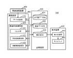
- FIG. 5is a functional block diagram of the management server 140 of this embodiment.
- the management server 140calculates a prediction function that can grasp the change in the road surface state using the transport vehicle data transmitted from each dump truck 120 and each motor grader 130, and presents it to the administrator. To do.
- the prediction functionuses the prediction function, the next scheduled repair time is calculated and presented to the administrator.
- the prediction function and the scheduled repair timeare calculated for each segment by dividing the travel path 101 into a plurality of regions (segments).
- the management server 140 of this embodimentincludes a wireless communication device 450, a data distribution unit 410, a road surface state calculation unit 420, a storage device 430, and a display device 440.
- the road surface state calculation unit 420estimates the current value, average value, deterioration rate, etc. of the road surface state for each segment. For this reason, the road surface state calculation unit 420 includes a prediction function calculation unit 422, a repair time estimation unit 423, and a reset unit 424.
- the storage device 430stores a travel road data DB 431, a road surface data DB 432, and an estimated value DB 433.
- the display device 440includes a display control unit 441 and a display 442.
- the wireless communication device 450is a communication interface that receives vehicle data transmitted from the dump truck 120 and the motor grader 130 via the wireless relay station 150. In the present embodiment, the received vehicle data is output to the data distribution unit 410.
- the travel route data DB 431stores the location data of the travel route 101 of the entire mine divided into segments. For example, as shown in FIG. 6A, the range specified by the coordinate value of the applied coordinate system is stored for each segment. The range of the segment may be determined based on data transmitted from the dump truck 120 while the dump truck 120 reciprocates the travel path 101 a plurality of times, for example. .
- the road surface data DB 432stores vehicle data received from each vehicle for each segment, as shown in FIG.
- a storage areais provided for each segment.
- a storage area provided for each segment in each databaseis referred to as a segment storage area.
- the estimated value DB 433stores the estimated value calculated by the road surface state calculation unit 420 for each segment.
- the estimated valueis, for example, a current value, an average value, a deterioration rate, or the like of the road surface condition for each segment.
- the data distribution unit 410is connected to the wireless communication device 450 and the travel route data DB 431.
- Each vehicle data received via the wireless communication device 450is stored in the road surface data DB 432 for each segment where the transmission source vehicle is located. Which segment the transmission source vehicle is located in is determined based on own vehicle position data in the vehicle data.
- the prediction function calculation unit 422is connected to the road surface data DB 432 and the estimated value DB 433. Then, the prediction function calculation unit 422 calculates a prediction function based on the road surface state data accumulated in the road surface data DB 432. The prediction function is calculated for each segment.
- the prediction function calculation unit 422plots road surface state data accumulated in a specific segment area of the road surface data DB 432 as shown in FIG.
- the horizontal axis of the graph of FIG. 7is time [hours], and the vertical axis is road surface condition data.
- the prediction function calculation unit 422performs fitting on the plot result by, for example, the least square method, and determines the approximate function as the prediction function 510. Then, the determined coefficient of the prediction function 510 is stored as an estimated value in the storage area of the estimated value DB 433 provided for the segment to be processed.
- the prediction function calculation unit 422approximates the plot result with a linear function.
- the coefficient stored as the estimated valueis the slope of the function. In this case, the slope indicates the deterioration rate.
- the prediction function calculation unit 422registers the latest value of the road surface state data registered in the road surface data DB 432 as the current value 520 of the road surface state in the estimated value DB 433. Furthermore, an average value 550 or a weighted average value of the most recent road surface state data may be registered as the current value of the road surface condition.
- the prediction function calculation unit 422may register all road surface state data used for calculation of the prediction function in the estimated value DB in association with the time.
- the repair time estimation unit 423is connected to the estimated value DB 433.
- the scheduled repair time 530is estimated as the repair time for each segment.
- the estimated repair timeis estimated by setting a road surface repair threshold 540 and extrapolating a prediction function to estimate the time when the value of the road surface condition data exceeds the road surface repair threshold.
- the calculated scheduled repair timeis stored in the estimated value DB 433.
- the reset unit 424is connected to the road surface data DB 432 and the estimated value DB 433, and resets (discards) the accumulated data.
- work state datawork presence data
- all road surface state data accumulated up to that point in the segment areaare stored. Reset.
- 0is registered as the current value in the estimated value DB 433 in association with the acquisition time of the work presence data.
- the prediction function calculation unit 422thereafter calculates the prediction function 510 using only the newly accumulated road surface state data as shown in FIG. This is considered that when the work presence data is registered, the segment of the traveling path 101 has been repaired by the motor grader 130 and leveled. For this reason, it is because a road surface state is considered to be an initial state.
- the reset unit 424resets the road surface state data of all the segment areas when data having a slip ratio ⁇ (t) of a threshold value or more is simultaneously registered in the road surface data DB 432 by a predetermined threshold value or more.
- the reason why the vehicle data having the slip ratio ⁇ (t) equal to or greater than the threshold value is output from a plurality of vehiclesis that the road surface state of the traveling road 101 is considered to have changed significantly due to external factors such as rainfall.
- the display control unit 441is connected to the estimated value DB 433.
- the display control unit 441generates display data to be displayed on the display 442 using the estimated value stored in the estimated value DB 433 and causes the display 442 to display the display data.
- the display dataincludes, for example, road surface state data shown in FIG. 7, a prediction function 510, a current value 520, an average value 550, and a scheduled repair time 530.
- management server 140may further include a voice output unit so as to notify the scheduled repair time 530 by voice.
- the management server 140is realized by an information processing apparatus including a CPU (arithmetic unit) 460, a memory, a storage unit 430, a communication interface (wireless communication unit 450), and an output unit (display unit 440).
- the calculation device 460implements the data distribution unit 410, the road surface state calculation unit 420, and the display control unit 441 by loading a program stored in the storage device 430 in advance into the memory and executing the program.
- the traveling road data DB 431, the road surface data DB 432, and the estimated value DB 433are stored in the storage device 430.
- FIG. 8is a processing flow of the road surface management processing of this embodiment.
- vehicle datais received from M (M is an integer of 1 or more) vehicles at substantially the same time.
- the data distribution unit 410compares the vehicle position data with the coordinates of the travel path data DB 431, determines the segment where the vehicle that is the transmission source of the processing target vehicle data is located (step S1102), and the corresponding segment.
- the road surface state data of the numberis registered in the corresponding segment area of the road surface data DB 432 (step S1103).
- the reset unit 424determines whether or not the slip ratio of the vehicle data registered in the road surface data DB 432 is equal to or less than the slip ratio threshold ⁇ th (step S1104).
- step S1104If the slip ratio is equal to or less than the slip ratio threshold ⁇ th (S1104; Yes), the process returns to step S1102, and the next vehicle data is processed (steps S1105 and 1106).
- Step S1110a road surface state calculation process is performed (step S1111), and the process ends.
- the reset unit 424increments the slip ratio counter ⁇ ct by 1 (step S1107). Then, in the vehicle data received at the same time, it is determined whether or not the number of vehicles having a slip ratio larger than the slip ratio threshold ⁇ th (high slip ratio vehicle) exceeds a predetermined number threshold Nth. Here, it is determined whether or not ⁇ ct is equal to the number threshold Nth (step S1108).
- the number threshold Nthis set to a value appropriate for such determination. For example, 40%, half of all vehicles, etc.
- step S1108when the number of high slip ratio vehicles reaches the number threshold Nth (Yes), the reset unit 424 sets a slip flag (step S1109), and proceeds to S1111.
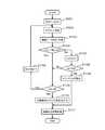
- FIG. 9is a processing flow of the road surface state calculation processing of this embodiment.
- the road surface state calculation processis performed only for the segment in which data is newly registered in the road surface data DB 432.
- the number of segments in which data is newly registeredis K.
- the road surface condition calculation unit 420first determines whether or not a slip flag is set (step S2101).
- the road surface state calculation unit 420determines whether or not the transmission source of the newly registered vehicle data is the dump truck 120 (step S2103). The determination is made based on the vehicle ID of the vehicle data.
- the prediction function calculation unit 422determines a prediction function using all the vehicle data stored in the segment area of the road surface data DB 432 (step S2104).
- the prediction function calculation unit 422obtains the calculated coefficient of the prediction function as the deterioration rate. Moreover, an average value is calculated using all the vehicle data accumulated in the segment area (step S2105). For example, when the prediction function is a linear function, the gradient is used as the deterioration rate.
- the prediction function calculation unit 422extrapolates the prediction function and predicts the scheduled repair time (step S2106).
- the prediction function calculation unit 422stores estimated values such as the calculated average value, deterioration rate, and scheduled repair time in the estimated value DB 433 (step S2107).
- the display control unit 441uses the data stored in the estimated value DB 433 to generate display image data and display it on the display 442, thereby updating the display on the display 442 (step S2108).
- step S2103determines whether or not work is registered as the work state data (step S2111). If there is no work, the process proceeds to step S2108.
- the reset unit 424performs a reset process for resetting all road surface state data of the currently processed segment (step S2112), and estimates 0 as the road surface state data. Register in the DB 433 and proceed to Step S2108.
- the road surface state calculation unit 420repeats the above processing for all segments for which data has been newly registered (steps S2109 and S2110), and ends the processing.
- the reset unit 424performs a reset process for resetting road surface state data of all segments in the road surface data DB 432 (step S2121). At this time, the reset unit 424 registers 0 as road surface state data for each segment of the estimated value DB 433.
- the display control unit 441generates display image data for all segments using the data in the estimated value DB 433 after the reset process, and updates the display on the display 442 by displaying the data on the display 442 (step S2123). Exit.
- the self-position data that is mounted on the dump truck 120 and is the position of the dump truck 120, the road surface state data of the travel path 101 of the dump truck 120, and the dump truck 120The vehicle-mounted on-vehicle terminal 121 that periodically transmits the slip rate, the self-position data that is mounted on the motor grader 130, the position data of the motor grader 130, the work state data, and the slip rate of the motor grader 130 are periodically transmitted.
- the repair vehicle in-vehicle terminal 131 and the management server 140are provided. Then, the management server 140 divides the traveling path 101 on which the dump truck 120 travels into a plurality of segments, and manages the road surface state of the traveling path 101 for each segment.
- the management server 140associates the segment including the position specified by the self-position data with the reception time and the road surface data. Accumulate in the road surface data DB 432. Further, each time the management server 140 receives the self-position data and the work status data indicating “work is present” from the motor grader 130, the management server 140 includes the position specified by the self-position data stored in the road surface data DB 432. Every time the road surface data of the segment is reset and new road surface state data is accumulated in the road surface data DB 432, the road surface of the segment based on a plurality of accumulated road surface state data for each segment. A prediction function for predicting a change in state due to time is determined, and a time for reaching a repair scheduled time road surface repair threshold is calculated according to the determined prediction function and output to an output device.
- the repair timeis predicted based on the determined prediction function. For this reason, it is possible to make a highly accurate prediction in accordance with the actual situation. Since the manager can make a repair plan based on this highly accurate prediction, a rational and highly accurate road surface maintenance plan can be made, and road surface management can be performed efficiently.
- the slip ratiois received from each vehicle, and the fluctuation of the slip ratio data is also monitored. Then, at the same time, when the slip rate from a predetermined number or more of vehicles exceeds a predetermined value, the prediction function is reset. This is because when the slip rate of a predetermined number or more vehicles is high at the same time, it means that it has become rainy. In this case, the prediction function for the entire mine is reset. That is, according to the present embodiment, not only the road surface state data but also the slip rate is taken into consideration to determine the road surface change state. For this reason, even if the road surface condition changes significantly due to changes in the weather, such as rain, it is possible to respond appropriately.
- road surface state data, slip ratio, and work state dataare calculated on the vehicle side and transmitted to the management server 140, respectively.
- the vehicle position data, the acquisition time, and the operation state datamay be transmitted from the vehicle to the management server 140 and may be calculated on the management server 140 side using these data.
- the estimated repair timeis displayed on the display 442 to notify the administrator.
- the notification method to the manageris not limited to this.
- the notificationmay be made by voice or the like.
- SYMBOLS 100Road surface management system, 101: Traveling road, 110: Work vehicle, 120: Dump truck (carrying vehicle), 121: Carrying vehicle vehicle-mounted terminal, 122: GPS receiver (satellite signal receiver), 123: 1st arithmetic unit , 124: first storage device, 130: motor grader (repair vehicle), 131: repair vehicle in-vehicle terminal, 133: second arithmetic device, 134: second storage device, 140: management server, 150: wireless relay station, 211: body, 212: front wheel, 213: rear wheel, 214: cargo bed, 215: cab, 216: front wheel side suspension, 217: rear wheel side suspension, 220: sensor, 221: speed sensor, 222: angle sensor, 224: Pressure sensor, 231: Own vehicle position calculation unit, 232: operation data collection unit, 233: operation data DB, 234: wireless communication device (first communication device), 235: road surface state estimation unit, 236: road surface
Landscapes
- Business, Economics & Management (AREA)
- Engineering & Computer Science (AREA)
- Human Resources & Organizations (AREA)
- Physics & Mathematics (AREA)
- General Physics & Mathematics (AREA)
- Economics (AREA)
- Strategic Management (AREA)
- Tourism & Hospitality (AREA)
- Marketing (AREA)
- Theoretical Computer Science (AREA)
- General Business, Economics & Management (AREA)
- Operations Research (AREA)
- Quality & Reliability (AREA)
- Entrepreneurship & Innovation (AREA)
- General Health & Medical Sciences (AREA)
- Primary Health Care (AREA)
- Health & Medical Sciences (AREA)
- Structural Engineering (AREA)
- Civil Engineering (AREA)
- Architecture (AREA)
- Marine Sciences & Fisheries (AREA)
- Mining & Mineral Resources (AREA)
- Animal Husbandry (AREA)
- Agronomy & Crop Science (AREA)
- Life Sciences & Earth Sciences (AREA)
- Development Economics (AREA)
- Game Theory and Decision Science (AREA)
- Traffic Control Systems (AREA)
- Road Repair (AREA)
- Management, Administration, Business Operations System, And Electronic Commerce (AREA)
Abstract
Description
Translated fromJapanese本発明は、運搬車両の走行路の路面状態を管理する技術に関する。特に、鉱山等の未舗装の走行路の路面状態を管理する技術に関する。The present invention relates to a technique for managing a road surface state of a traveling path of a transport vehicle. In particular, the present invention relates to a technique for managing the road surface state of an unpaved road such as a mine.
鉱山の採掘現場等、未舗装の走行路を運搬車両が繰り返し走行することで劣化する路面を保守管理する技術がある。例えば、特許文献1には、「管理装置は、管理側無線通信装置を介してダンプトラックの稼働情報を収集する。ダンプトラックの稼働情報に含まれる、ダンプトラックが排土した場所から積荷を積み込む場所に移動し再び排土する場所に移動するまでの経路に含まれる少なくとも4箇所の位置情報に基づき、ダンプトラックが走行した経路Rg、Rrを特定する(要約抜粋)」鉱山機械の管理システムが開示されている。There is a technology to maintain and manage road surfaces that deteriorate due to repeated travel of transport vehicles on unpaved roads such as mining sites. For example,
特許文献1に開示の技術は、上記手法で特定された走行路の路面凹凸を、ダンプトラックの稼働情報を用いて検知し、路面整備計画を立てる。しかしながら、一般に、上述のような環境においては、運搬車両だけでなく、走行路を補修する補修車両も、同時に走行し、路面状況が劣化した箇所の補修を行っている。特許文献1に開示の技術では、このような補修車両による補修は全く考慮されていない。また、凹凸の発生には、運搬車両の走行という経時的で局所的な要因と、降雨等の突発的で全体的な要因とがある。しかしながら、特許文献1に開示の技術では、両者の違いは全く考慮されていない。これらの理由から、特許文献1に開示の技術では、合理的で高精度な路面整備計画を得ることができない。The technique disclosed in
本発明は、上記事情に鑑みてなされたもので、鉱山等の未舗装の走行路を運搬車両が繰り返し走行する環境において、効率的な路面管理を可能とし、路面整備作業の効率化を図る技術を提供することを目的とする。The present invention has been made in view of the above circumstances, and is a technique for enabling efficient road surface management and improving the efficiency of road surface maintenance work in an environment where a transport vehicle repeatedly travels on an unpaved traveling road such as a mine. The purpose is to provide.
本発明は、運搬車両が走行する走行路を複数のセグメントに分割し、セグメント毎に前記走行路の路面状態を管理する路面管理システムであって、演算装置と記憶装置と出力装置と通信装置とを備える管理サーバと、前記運搬車両に搭載され、第1演算装置と第1通信装置とを備える運搬車両車載端末と、前記走行路を補修する補修車両に搭載され、第2演算装置と第2通信装置とを備える補修車両車載端末と、を備え、前記第1演算装置は、前記運搬車両に取り付けられたセンサから入力された信号に基づき前記走行路の路面状態データを算出し、算出した前記路面状態データを、当該運搬車両の位置データである運搬車両位置データとともに、前記第1通信装置を介して前記管理サーバに送信し、前記第2演算装置は、前記補修車両に取り付けられたセンサから入力された信号に基づき当該補修車両の作業状態を示す作業状態データを算出し、算出した前記作業状態データを、当該補修車両の位置データである補修車両位置データとともに、前記第2通信装置を介して前記管理サーバに送信し、前記演算装置は、前記通信装置と前記記憶装置と前記出力装置とに接続され、前記通信装置で前記運搬車両位置データおよび前記路面状態データを受信する毎に、当該運搬車両位置データで特定される位置を含む前記セグメントと受信時刻と当該路面状態データとを対応づけて前記記憶装置に蓄積し、前記通信装置で前記補修車両位置データおよび作業有を示す前記作業状態データを受信する毎に、当該補修車両位置データで特定される位置を含む前記セグメントに対応づけて前記記憶装置に蓄積された前記路面状態データをリセットし、前記記憶装置に新たに前記路面状態データが蓄積される毎に、前記セグメント毎に、蓄積された複数の前記路面状態データに基づいて当該セグメントの路面状態の時間による変化を予測する予測関数を決定し、決定した前記予測関数に従って、補修予定時刻として路面補修閾値に達する時間を算出し、前記出力装置に算出した前記補修予定時刻を出力することを特徴とする路面管理システムを提供する。The present invention is a road surface management system that divides a traveling road on which a transport vehicle travels into a plurality of segments and manages the road surface state of the traveling road for each segment, and includes an arithmetic device, a storage device, an output device, and a communication device. And a management vehicle equipped with a management vehicle, a transportation vehicle on-board terminal equipped with a first arithmetic device and a first communication device, and a repair vehicle for repairing the travel path, a second computation device and a second computing device. A repair vehicle in-vehicle terminal provided with a communication device, wherein the first calculation device calculates road surface state data of the traveling road based on a signal input from a sensor attached to the transport vehicle, Road surface state data is transmitted to the management server via the first communication device together with transport vehicle position data, which is the position data of the transport vehicle, and the second arithmetic unit sends the repair vehicle to the repair vehicle. Based on the signal input from the attached sensor, the work state data indicating the work state of the repair vehicle is calculated, and the calculated work state data together with the repair vehicle position data which is the position data of the repair vehicle. The arithmetic device is connected to the communication device, the storage device, and the output device, and the transport vehicle position data and the road surface state data are transmitted by the communication device. Each time it is received, the segment including the position specified by the transport vehicle position data, the reception time, and the road surface state data are stored in the storage device in association with each other, and the repair vehicle position data and work are stored in the communication device. Each time the work status data indicating existence is received, the segment is associated with the segment including the position specified by the repair vehicle position data. Each time the road surface state data accumulated in the storage device is reset and the road surface state data is newly accumulated in the storage device, the segment is determined based on the accumulated plurality of road surface state data for each segment. A prediction function for predicting a change in the road surface condition with time is determined, a time for reaching a road surface repair threshold is calculated as a scheduled repair time according to the determined prediction function, and the calculated scheduled repair time is output to the output device The road surface management system characterized by this is provided.
本発明によれば、鉱山等の未舗装の走行路を運搬車両が繰り返し走行する環境において、効率的な路面管理が可能となり、路面整備作業の効率が向上する。前述した以外の課題、構成及び効果は、以下の実施形態の説明により明らかにされる。According to the present invention, efficient road surface management is possible in an environment in which a transport vehicle repeatedly travels on an unpaved road such as a mine, and the efficiency of road surface maintenance work is improved. Problems, configurations, and effects other than those described above will become apparent from the following description of embodiments.
以下、本発明に係る実施形態を、図に基づいて説明する。以下、本明細書において、同一機能を有するものは、特に断らない限り同一の符号を付し、繰り返しの説明は省略する。Hereinafter, embodiments according to the present invention will be described with reference to the drawings. Hereinafter, in this specification, those having the same function are denoted by the same reference numerals unless otherwise specified, and repeated description is omitted.
本実施形態の路面管理システムは、主として鉱山等の未舗装の走行路を運搬車両が繰り返し走行する環境で用いられる。本実施形態の路面管理システムでは、運搬車両から受信する位置情報および走行路の路面情報と、補修車両から受信する位置情報および作業情報とを用いて、路面状態予測関数を決定する。その予測関数を用いて、補修すべき時期を予測し、報知する。このとき、予測関数の決定とは独立として、天候による路面の変化を加味する。以下、これらの機能に主眼をおいて、本実施形態の路面管理システムを説明する。The road surface management system of the present embodiment is mainly used in an environment in which a transport vehicle repeatedly travels on an unpaved travel path such as a mine. In the road surface management system of the present embodiment, the road surface state prediction function is determined using the position information received from the transport vehicle and the road surface information of the traveling road, and the position information and work information received from the repair vehicle. The prediction function is used to predict and notify when to repair. At this time, the change of the road surface due to the weather is taken into consideration independently of the determination of the prediction function. Hereinafter, the road surface management system of the present embodiment will be described focusing on these functions.
図1は、本実施形態の路面管理システム100の概略構成図である。本実施形態の路面管理システム100は、作業車両110と、運搬車両120と、補修車両130と、管理サーバ140と、無線中継局150と、を備える。なお、作業車両110、運搬車両120、補修車両130の台数、無線中継局150の個数は問わない。また、本実施形態では、路面管理システムは、鉱山内で用いられる場合を例にあげて説明する。FIG. 1 is a schematic configuration diagram of a road
作業車両110は、例えば、ショベル等であり、掘削作業や積込作業等を行う。作業車両110は、鉱山内の積込場に配置される。
運搬車両120は、例えば、ダンプトラック等であり、作業車両110で掘削された砕石や土砂等の掘削物を、積込場から放土場へ運搬する。運搬時は、鉱山内の走行路101を走行する。以下、本実施形態では、運搬車両120をダンプトラック120として説明する。ダンプトラック120は、運搬車両車載端末121(図2(b)参照)を備える。The
補修車両130は、例えば、モータグレーダやブルドーザ等である。鉱山では、上述のように、走行路101は舗装されていない。このため、重量の大きいダンプトラック120により繰り返される往復走行や降雨等により、走行路101の路面状況は悪化する。補修車両130は、このような事情で悪化した走行路101の路面を修復する。以下、本実施形態では、補修車両130をモータグレーダ130として説明する。モータグレーダ130は、補修車両車載端末131(図4(b)参照)を備える。The
管理サーバ140は、鉱山内の管理局に配置される。無線中継局150を介して、運搬車両車載端末121および補修車両車載端末131とデータの送受信を行う。本実施形態では、これらの運搬車両車載端末121および補修車両車載端末131から受信したデータを処理し、鉱山内の走行路101の路面を管理する。
[ダンプトラック]
まず、ダンプトラック120の構成について説明する。図2(a)は、ダンプトラック120の外観の側面図であり、図2(b)は、ダンプトラック120が備える運搬車両車載端末121の機能ブロック図である。[Dump truck]
First, the configuration of the
ダンプトラック120は、図2に示すように、車体211と、左右それぞれの前輪212と、左右それぞれの後輪213と、荷台214と、キャブ215と、左右それぞれの前輪側サスペンション216と、左右それぞれの後輪側サスペンション217と、各種のセンサ220を備える。上記運搬車両車載端末121は、例えば、キャブ215内に配置される。As shown in FIG. 2, the
左右の前輪側サスペンション216は、それぞれ、車体211と左右の前輪212の間に設けられる。左右の後輪側サスペンション217は、それぞれ、車体211と左右の後輪213の間に設けられる。4つのサスペンション216、217は、例えば、油圧シリンダである。The left and right front
本実施形態では、各種のセンサ220として、図2(b)に示すように、速度センサ221と、角度センサ222と、圧力センサ224と、を備える。In this embodiment, as
速度センサ221は、左右の前輪212、左右の後輪213それぞれの軸に設けられ、各軸の回転速度を独立して検出する。The
角度センサ222は、車体211に設けられ、車体211の傾斜角を検出する。例えば、振り子センサ、MEMS等が用いられる。The
圧力センサ224は、前輪側サスペンション216、後輪側サスペンション217にそれぞれ設けられ、油圧シリンダの圧力を検出するサスペンション圧センサである。検出した圧力は、サスペンション圧として出力される。The pressure sensor 224 is a suspension pressure sensor that is provided in each of the front
また、本実施形態のダンプトラック120は、衛星信号受信装置122を備える。衛星信号受信装置122は、例えば、GPS(Global Positioning System)衛星等、複数の航法衛星からの信号を受信する。以下、本実施形態では、衛星信号受信装置122を、GPS受信装置122と呼ぶ。また、受信する航法衛星からの信号も、GPS信号と呼ぶ。Also, the
[運搬車両車載端末]
運搬車両車載端末121は、図2(b)に示すように、各種のセンサ220およびGPS受信装置122に接続され、これらで取得したデータを処理し、管理サーバ140に送信する。本実施形態では、さらに、走行路101の路面状況とスリップ率とを算出し、位置情報とともに管理サーバ140に送信する。[Vehicle vehicle terminal]
The transport vehicle in-
これを実現するため、本実施形態の運搬車両車載端末121は、図2(b)に示すように、自車位置演算部231と、稼働データ収集部232と、稼働データデータベース(DB)233と、無線通信装置(第1通信装置)234と、路面状態推定部235と、路面状態データベース(DB)236と、を備える。In order to realize this, as shown in FIG. 2 (b), the transport vehicle in-
自車位置演算部231は、GPS受信装置122と稼働データDB233とに接続される。自車位置演算部231は、GPS受信装置122で受信したGPS信号を取得し、そのGPS信号を用いて自車位置を算出する。ここでは、GPS信号を利用した測位方式であるGNSS(Global Navigation Satellite System;全地球航法衛星システム)を用いる。そして、算出した自車位置データを、GPS信号受信時刻とともに、稼働データDB233に記憶する。The own vehicle
なお、用いる航法衛星は、上述のように、GPS衛星に限定されない。例えば、GLONASS、Galileo、準天頂衛星(QZSS)等の衛星測位システムや、これらの組み合わせであってもよい。Note that the navigation satellite used is not limited to the GPS satellite as described above. For example, a satellite positioning system such as GLONASS, Galileo, Quasi-Zenith Satellite (QZSS), or a combination thereof may be used.
本実施形態では、推定する自車位置は、予め定めた座標系の座標値とする。座標系は、例えば、鉱山独自の座標系であってもよいし、座標値が緯度経度の緯度経度座標系を用いてもよい。以下、単に適用座標系と呼ぶ。また、以下、GPS信号受信時刻を取得時刻と呼ぶ。In this embodiment, the estimated vehicle position is a coordinate value of a predetermined coordinate system. The coordinate system may be, for example, a coordinate system unique to the mine, or a latitude / longitude coordinate system having coordinate values of latitude / longitude. Hereinafter, this is simply referred to as an applicable coordinate system. Hereinafter, the GPS signal reception time is referred to as acquisition time.
稼働データ収集部232は、ダンプトラック120の各部に取り付けられた各種センサ220と稼働データDB233とに接続される。各種センサ220からは、当該センサ220が検出したダンプトラック120の各部のセンサ信号を稼働データとして収集する。本実施形態では、例えば、速度センサ221からの各車輪の速度データ、角度センサ222からの角度データ、圧力センサ224からの各サスペンションの圧力データ(以下、サス圧データと呼ぶ。)を、稼働データとして収集する。The operation
なお、本実施形態では、各センサ信号およびGPS信号は、周期的に、略同時刻に取得されるものとする。そして、これらの信号値(データ)は、取得時刻とともに、稼働データDB233に出力される。In this embodiment, it is assumed that each sensor signal and GPS signal are periodically acquired at approximately the same time. These signal values (data) are output to the
稼働データDB233は、自車位置演算部231と稼働データ収集部232とが収集した自車位置データおよび稼働データを記憶する。本実施形態では、それぞれ、取得時刻に対応づけて記憶する。The
路面状態推定部235は、稼働データDB233に接続される。路面状態推定部235は、稼働データDB233に格納される稼働データを用いて、走行路101の路面の状態を推定する。本実施形態では、路面状態推定部235は、路面の状態を示す指数として、路面状態量(路面状態データ)とスリップ率とを算出する。The road surface
本実施形態では、路面状態推定部235は、路面状態データを、ダンプトラック120のサス圧データと速度データとを用いて算出する。具体的には、以下の式(1)に従って、時刻tに取得された上記データを用いて路面状態データh(t)を算出する。
h(t)=αA/v ・・・(1)
ここで、Aは、サス圧データに関する時刻t前後の所定時間β内すなわちt-βからt+βまでの変動係数であり、vは、時刻tに取得された速度(m/sec)、αは係数である。In the present embodiment, the road surface
h (t) = αA / v (1)
Here, A is a coefficient of variation within a predetermined time β before and after time t relating to the suspension pressure data, that is, from t−β to t + β, v is a speed (m / sec) acquired at time t, and α is a coefficient. It is.
また、路面状態推定部235は、スリップ率を、速度センサ221が取得したダンプトラック120の速度データを用いて算出する。具体的には、例えば、以下の式(2)に従って、時刻tに取得された上記データを用いスリップ率λ(t)を算出する。
λ(t)=|(Vr-V)/Max{Vr,V}| ・・・(2)
ここで、Vrは、時刻tの駆動輪の車輪速度、Vは、時刻tの従動輪の車輪速度、Max{}は、{}内の値の最大値を返す関数であり、||は、||内の値の絶対値を示す(例えば、特許第5336447号公報参照)。本実施形態では、例えば、後輪213の速度センサ221からの速度データを、駆動輪の車輪速度とし、前輪212の速度センサ221からの速度データを従動輪の車輪速度として用いる。Further, the road surface
λ (t) = | (Vr−V) / Max {Vr, V} | (2)
Here, Vr is the wheel speed of the driving wheel at time t, V is the wheel speed of the driven wheel at time t, Max {} is a function that returns the maximum value in {}, and || || indicates the absolute value of the value in (| for example, patent 5336447 gazette). In the present embodiment, for example, the speed data from the
なお、路面状態データh(t)およびスリップ率λ(t)の算出は、上記手法に限定されない。例えば、路面状態データh(t)は、時刻tのサス圧データの、平坦な路面を一定速度で走行する際のサス圧データに対する比を用いて算出してもよい(例えば、特開2013-166425号公報参照)。また、所定時間内の、サス圧データの最大振幅および周波数を求め、これらの値を路面状態データh(t)としてもよい(例えば、国際公開2015-140966号公報参照)。The calculation of the road surface condition data h (t) and the slip ratio λ (t) is not limited to the above method. For example, the road surface condition data h (t) may be calculated by using the ratio of the suspension pressure data at time t to the suspension pressure data when traveling on a flat road surface at a constant speed (for example, Japanese Patent Application Laid-Open No. 2013-2013). 166425). Further, the maximum amplitude and frequency of the suspension pressure data within a predetermined time may be obtained, and these values may be used as the road surface condition data h (t) (see, for example, International Publication No. 2015-140966).
算出した路面状態データh(t)およびスリップ率λ(t)は、算出に用いた稼働データの取得時刻t、および、同時刻に取得した自車位置データに対応づけて、路面状態DB236に格納される。なお、稼働データと同時刻に取得した自車位置データが無い場合は、最も近い時刻に取得した自車位置データに対応づけて格納してもよい。The calculated road surface state data h (t) and slip ratio λ (t) are stored in the road
ここで、路面状態DB236の一例を図3(a)に示す。本図に示すように、路面状態DB236は、自車位置236bと、時刻236cと、路面状態データ236dと、スリップ率236eと、を備える。さらに、ダンプトラック120毎に一意に付与される車両IDを備えていてもよい。Here, an example of the road
無線通信装置234は、管理サーバ140とデータの送受信を行う。本実施形態では、路面状態DB236に接続され、路面状態DB236に新たなデータが格納される毎に、運搬車両データとして管理サーバ140に送信される。なお、運搬車両データは、周期的に、あるいは、管理サーバ140からの求めに応じて送信されてもよい。The
ダンプトラック120から、管理サーバ140に送信される運搬車両データ237の一例を図3(b)に示す。運搬車両データ237は、図3(b)に示すように、車両ID237aと、自車位置データ237bと、時刻237cと、路面状態237dと、スリップ率237eと、を含む。An example of the
なお、無線通信装置234は、稼働データDB233にも接続され、周期的、あるいは、管理サーバ140からの求めに応じて、稼働データDB233に格納されるデータを管理サーバ140に出力してもよい。The
本実施形態の運搬車両車載端末121は、例えば、第1演算装置(CPU)123とメモリと第1記憶装置124と通信インタフェース(無線通信装置234)とを備える汎用情報処理装置で実現される。第1演算装置123が、予め第1記憶装置124に格納されたプログラムをメモリにロードして実行することにより、自車位置演算部231と、稼働データ収集部232と、路面状態推定部235と、を実現する。稼働データDB233および路面状態DB236は、第1記憶装置124に格納される。The transport vehicle in-
また、運搬車両車載端末121は、処理内容を表示させる表示制御部およびディスプレイを備えていてもよい。Further, the transport vehicle in-
[モータグレーダ]
次に、モータグレーダ130について説明する。図4(a)は、モータグレーダ130の外観の側面図であり、図4(b)は、モータグレーダ130が備える補修車両車載端末131の機能ブロック図である。[Motor grader]
Next, the
本実施形態のモータグレーダ130は、ブレード311とブレードを駆動するブレードアクチュエータ312とを備える。また、センサ320として、図4(b)に示すように、速度センサ321と、角度センサ322と、ブレード角度センサ323とを備える。また、ダンプトラック120同様、航法衛星からの信号を受信する、衛星信号受信装置(GPS受信装置)132を備える。また、補修車両車載端末131は、例えば、運転室内に配置される。The
[補修車両車載端末]
補修車両車載端末131は、図3(b)に示すように、センサ320およびGPS受信装置122に接続され、これらで取得したデータを処理し、管理サーバ140に送信する。本実施形態では、補修車両車載端末131は、さらに、モータグレーダ130が補修作業を行ったか否かを検出し、検出結果(作業状態データ)を自己位置データとともに管理サーバ140に送信する。[Repair vehicle on-board terminal]
As shown in FIG. 3B, the repair vehicle in-
これを実現するため、本実施形態の補修車両車載端末131は、図4(b)に示すように、自車位置演算部331と、稼働データ収集部332と、稼働データベース(DB)333と、無線通信装置(第2通信装置)334と、作業状態推定部335と、作業状態データベース(DB)336と、を備える。In order to realize this, the repair vehicle in-
自車位置演算部331、稼働データ収集部332、稼働データDB333、無線通信装置334は、運搬車両車載端末121の同名のものと、基本的に同機能であるため、ここでは、詳細な説明を省略する。ただし、無線通信装置334は、作業状態DB336に接続され、後述の補修車両データを、管理サーバ140に送信する。The own vehicle
作業状態推定部335は、モータグレーダ130が作業しているか否かの情報を取得する。本実施形態では、稼働データDB333に接続され、角度センサ322とブレード角度センサ323とから取得して格納されたセンサ信号(稼働データ)に基づき、作業状態であるか否かを判別する。The work
作業状態推定部335は、例えば、これらの稼働データを用いて、ブレード311の下端側の先端部の高さ位置を3次元位置として算出し、予め定めた高さ閾値以下となった場合、作業状態と判別する。判別結果は、作業状態データとして、上述の路面状態データ同様、算出に用いた稼働データの取得時刻、および、同時刻に取得した自車位置データに対応づけて、作業状態DB336に格納される。The work
また、本実施形態の作業状態推定部335は、ダンプトラック120の路面状態推定部235同様に、速度センサ221で取得される速度データを用いて、スリップ率を算出する。Also, the work
ここで、作業状態DB336の一例を、図3(c)に示す。本図に示すように、作業状態DB336は、自車位置336bと、時刻336cと、作業状態データ336dと、スリップ率336eと、を備える。さらに、モータグレーダ130毎に一意に付与される車両IDを備えていてもよい。なお、作業状態データ336dは、作業有と判別された場合は、1を、その他の場合は、0を格納する場合を例示する。Here, an example of the
また、本実施形態のモータグレーダ130から、管理サーバ140に送信される補修車両データ337の一例を図3(d)に示す。補修車両データ337は、図3(d)に示すように、車両ID337aと、自車位置337bと、時刻337cと、作業状態データ337dと、スリップ率337eと、を含む。FIG. 3D shows an example of
補修車両車載端末131も、運搬車両車載端末121同様、第2演算装置(CPU)133とメモリと第2記憶装置134と通信インタフェース(無線通信装置334)とを備える汎用情報処理装置で実現される。第2演算装置133が、予め第2記憶装置134に格納されたプログラムをメモリにロードして実行することにより、自車位置演算部331と、稼働データ収集部332と、作業状態推定部335と、を実現する。稼働データDB333および作業状態DB336は、第2記憶装置134に格納される。The repair vehicle in-
また、補修車両車載端末131は、処理内容を表示させる表示制御部およびディスプレイを備えていてもよい。Moreover, the repair vehicle in-
以下、ダンプトラック120およびモータグレーダ130を区別する必要が無い場合、両者を単に車両と呼ぶ。また、運搬車両データ237および補修車両データ337も、特に区別する必要が無い場合は、両者を単に車両データと呼ぶ。Hereinafter, when it is not necessary to distinguish the
[管理サーバ]
次に、管理サーバ140について説明する。図5は、本実施形態の管理サーバ140の機能ブロック図である。[Management Server]
Next, the
本実施形態では、管理サーバ140は、各ダンプトラック120および各モータグレーダ130から送信される運搬車両データを用いて、路面状態の変化の様子を把握可能な予測関数を算出し、管理者に提示する。また、予測関数を用い、次回の補修予定時刻を算出し、管理者に提示する。なお、予測関数および補修予定時刻は、走行路101を複数の領域(セグメント)に分割し、セグメント毎に算出される。In the present embodiment, the
これを実現するため、本実施形態の管理サーバ140は、無線通信装置450と、データ分配部410と、路面状態演算部420と、記憶装置430と、表示装置440と、を備える。In order to realize this, the
路面状態演算部420は、セグメント毎に、路面状態の現在値、平均値、劣化速度等を推定する。このため、路面状態演算部420は、予測関数算出部422と、補修時期推定部423と、リセット部424とを備える。また、記憶装置430には、走行路データDB431と、路面データDB432と、推定値DB433とが格納される。表示装置440は、表示制御部441と、ディスプレイ442と、を備える。The road surface
無線通信装置450は、ダンプトラック120およびモータグレーダ130から送信される車両データを、無線中継局150を介して受信する通信インタフェースである。本実施形態では、受信した車両データを、データ分配部410に出力する。The
走行路データDB431は、鉱山全体の走行路101の位置データを、セグメントに分けて記憶する。例えば、図6(a)に示すように、適用座標系の座標値で特定される範囲が、セグメント毎に格納される。なお、セグメントの範囲は、走行路101の位置データは、例えば、ダンプトラック120が、複数回、走行路101を往復する間に、ダンプトラック120から送信されるデータに基づいて決定してもよい。The travel
路面データDB432は、図6(b)に示すように、各車両から受信した車両データを、セグメント毎に記憶する。記憶領域は、セグメント毎に設けられる。以下、各データベースの、セグメント毎に設けられる記憶領域を、セグメント記憶領域と呼ぶ。The road
推定値DB433は、セグメント毎に、路面状態演算部420が算出した推定値を格納する。推定値は、後述するように、例えば、セグメント毎の路面状態の現在値、平均値、劣化速度等である。The estimated
データ分配部410は、無線通信装置450と走行路データDB431とに接続される。無線通信装置450を介して受信した各車両データを、送信元の車両が位置するセグメント毎に路面データDB432に記憶する。送信元の車両がいずれのセグメントに位置するかは、車両データ内の自車位置データに基づき判別する。The
予測関数算出部422は、路面データDB432と推定値DB433とに接続される。そして、予測関数算出部422は、路面データDB432に蓄積された路面状態データに基づき、予測関数を算出する。予測関数は、セグメント毎に算出される。The prediction
具体的には、例えば、予測関数算出部422は、路面データDB432の特定のセグメントの領域に蓄積された路面状態データを、図7に示すようにプロットする。図7のグラフの横軸は時刻[hours]、縦軸は路面状態データである。Specifically, for example, the prediction
そして、予測関数算出部422は、プロット結果に対し、例えば、最小二乗法等でフィッティングを行い、近似関数を予測関数510として決定する。そして、決定した予測関数510の係数を推定値として、推定値DB433の、処理対象のセグメント用に設けられた記憶領域に記憶する。Then, the prediction
例えば、図7の例では、予測関数算出部422は、プロット結果を一次関数で近似する。推定値として記憶する係数は、関数の傾きである。この場合、傾きは、劣化速度を示す。For example, in the example of FIG. 7, the prediction
なお、予測関数算出部422は、路面データDB432に登録された路面状態データの最新の値を、路面状態の現在値520として、推定値DB433に登録する。さらに、直近の複数の路面状態データの平均値550もしくは重み付き平均値を、路面状況の現在値として登録してもよい。The prediction
また、予測関数算出部422は、予測関数算出に用いた全ての路面状態データを、時刻に対応づけて、推定値DBに登録してもよい。Also, the prediction
補修時期推定部423は、推定値DB433に接続される。予測関数算出部422が算出した予測関数510を用いて、セグメント毎に補修時期として補修予定時刻530を推定する。補修予定時刻の推定は、例えば、路面補修閾値540を定めておき、予測関数を外挿することにより、路面状況データの値が当該路面補修閾値を超える時刻を推定する。算出した補修予定時刻は、推定値DB433に記憶する。The repair
リセット部424は、路面データDB432と推定値DB433とに接続され、蓄積されているデータをリセット(破棄)する。本実施形態では、路面データDB432に、作業を行ったことを示す作業状態データ(作業有データ)が登録されると、当該セグメント領域の、その時点までに蓄積されていた全ての路面状態データをリセットする。また、推定値DB433に、作業有データの取得時刻に対応づけて、現在値として0を登録する。The
これにより、推定値DB433には、路面状態データとして0が登録される。また、路面データDB432には、蓄積データがなくなるため、予測関数算出部422は、図7に示すように、その後、新たに蓄積された路面状態データのみを用いて、予測関数510を算出する。これは、作業有データが登録される場合、走行路101の当該セグメントは、モータグレーダ130により、補修作業が行われて整地されたものと考えられる。このため、路面状態は、初期状態となると考えられるためである。Thereby, 0 is registered in the estimated
また、リセット部424は、路面データDB432に、スリップ率λ(t)が閾値以上のデータが、同時に、予め設定した閾値以上登録されると、全セグメント領域の路面状態データをリセットする。スリップ率λ(t)が閾値以上の車両データが複数の車両から出力されるのは、降雨等の外的要因によって走行路101の路面状態が大幅に変化したと考えられるためである。Further, the
表示制御部441は、推定値DB433に接続される。表示制御部441は、推定値DB433に格納されている推定値を用いて、ディスプレイ442に表示する表示データを生成し、ディスプレイ442に表示させる。表示データには、例えば、図7に示す路面状態データと、予測関数510と、現在値520と、平均値550と、補修予定時刻530とが含まれる。The
なお、管理サーバ140は、さらに音声出力部を備え、補修予定時刻530を、音声で報知するよう構成してもよい。Note that the
本実施形態の管理サーバ140は、CPU(演算装置)460とメモリと記憶装置430と通信インタフェース(無線通信装置450)と出力装置(表示装置440)とを備える情報処理装置で実現される。演算装置460が、予め記憶装置430に格納されたプログラムをメモリにロードして実行することにより、データ分配部410と、路面状態演算部420と、表示制御部441と、を実現する。走行路データDB431と、路面データDB432と、推定値DB433とは、記憶装置430に格納される。The
次に、本実施形態の管理サーバ140による路面管理処理の流れを説明する。図8は、本実施形態の路面管理処理の処理フローである。以下、実質的に同時刻に、M(Mは1以上の整数)台の車両から、車両データを受信するものとする。Next, the flow of road surface management processing by the
データ分配部410は、データ数カウンタMctおよびスリップ率カウンタλctを初期化する(ステップS1101)。ここでは、Mct=1、λct=とする。The
次に、データ分配部410は、自車位置データと、走行路データDB431の座標を比較し、処理対象の車両データの送信元の車両の位置するセグメントを判定し(ステップS1102)、該当するセグメント番号の路面状態データを路面データDB432の対応するセグメント領域に登録する(ステップS1103)。Next, the
次に、リセット部424は、路面データDB432に登録された車両データのスリップ率が、スリップ率閾値λth以下であるか否かを判別する(ステップS1104)。Next, the
スリップ率がスリップ率閾値λth以下である場合(S1104;Yes)、ステップS1102へ戻り、次の車両データを処理する(ステップS1105、1106)。If the slip ratio is equal to or less than the slip ratio threshold λth (S1104; Yes), the process returns to step S1102, and the next vehicle data is processed (steps S1105 and 1106).
そして、データ分配部410が、M台分の処理を終えると、路面状態演算部420は、新たに登録されたセグメントの数を重複を除いてカウントし、これをK(Kは1以上の整数)として(ステップS1110)、路面状態演算処理を行い(ステップS1111)、処理を終了する。When the
一方、スリップ率がスリップ率閾値λthより大きい場合(S1104;No)、リセット部424は、スリップ率カウンタλctを1インクリメントする(ステップS1107)。そして、同時刻に受信した車両データ内で、スリップ率がスリップ率閾値λthより大きい車両(高スリップ率車両)の台数が、予め定めた台数閾値Nthを超えたか否かを判別する。ここでは、λctが台数閾値Nthと等しいか否かを判別する(ステップS1108)。On the other hand, when the slip ratio is larger than the slip ratio threshold λth (S1104; No), the
本実施形態では、所定数の車両のスリップ率がスリップ率閾値を超えた場合、雨天であり、路面状況が大幅に変化すると判断する。このため、台数閾値Nthは、このような判断に適切な値に設定する。例えば、全車両の4割、半数、等とする。In this embodiment, when the slip ratio of a predetermined number of vehicles exceeds the slip ratio threshold, it is determined that it is raining and the road surface condition changes significantly. For this reason, the number threshold Nth is set to a value appropriate for such determination. For example, 40%, half of all vehicles, etc.
高スリップ率車両の台数が、台数閾値Nthより少ない場合(S1108;No)は、ステップS1105へ移行し、処理を続ける。When the number of high slip ratio vehicles is smaller than the number threshold Nth (S1108; No), the process proceeds to step S1105 and the processing is continued.
なお、ステップS1108において、高スリップ率車両の台数が、台数閾値Nthとなった場合(Yes)、リセット部424は、スリップフラグを設定し(ステップS1109)、S1111へ移行する。In step S1108, when the number of high slip ratio vehicles reaches the number threshold Nth (Yes), the
次に、上記ステップS1111の、路面状態演算部420による、路面状態演算処理の流れを説明する。図9は、本実施形態の路面状態演算処理の処理フローである。ここでは、路面状態演算処理は、路面データDB432に、新たにデータが登録されたセグメントについてのみ行う。ここで、新たにデータが登録されたセグメント数はK個である。Next, the flow of the road surface state calculation process by the road surface
路面状態演算部420は、まず、スリップフラグが設定されているか否かを判別する(ステップS2101)。The road surface
スリップフラグが設定されていない場合、以下の処理を、路面データDB432に新たにデータが登録された全セグメント(K個)について繰り返す。このため、まず、セグメントカウンタKctを初期化(Kct=1)とする(ステップS2102)。When the slip flag is not set, the following process is repeated for all segments (K) for which data is newly registered in the road
まず、路面状態演算部420は、新たに登録された車両データの送信元がダンプトラック120であるかを判別する(ステップS2103)。判別は、車両データの車両IDで行う。First, the road surface
送信元がダンプトラック120である場合、予測関数算出部422は、路面データDB432の当該セグメント領域に蓄積されている全車両データを用いて、予測関数を決定する(ステップS2104)。When the transmission source is the
予測関数算出部422は、算出した予測関数の係数を、劣化速度として得る。また、当該セグメント領域に蓄積されている全車両データを用いて、平均値を算出する(ステップS2105)。劣化速度は、例えば、予測関数が一次関数の場合、その傾きを用いる。The prediction
次に、予測関数算出部422は、予測関数を外挿し、補修予定時刻を予測する(ステップS2106)。Next, the prediction
そして、予測関数算出部422は、算出した平均値、劣化速度および補修予定時刻等の推定値を、推定値DB433に格納する(ステップS2107)。Then, the prediction
次に、表示制御部441は、推定値DB433に格納されたデータを用いて、表示画像データを生成し、ディスプレイ442に表示させることにより、ディスプレイ442の表示を更新する(ステップS2108)。Next, the
一方、ステップS2103で、送信元がモータグレーダ130と判別された場合、リセット部424は、作業状態データとして、作業有が登録されているか否かを判別する(ステップS2111)。作業無しの場合は、そのまま、ステップS2108へ移行する。On the other hand, if it is determined in step S2103 that the transmission source is the
一方、ステップS2111で作業有が登録されている場合は、リセット部424は、現在処理中のセグメントの全路面状態データをリセットするリセット処理を行い(ステップS2112)、路面状態データとして0を推定値DB433に登録し、ステップS2108へ移行する。On the other hand, if the work presence is registered in step S2111, the
以上の処理を、路面状態演算部420は、新たにデータが登録された全セグメントについて、繰り返し(ステップS2109、S2110)、処理を終了する。The road surface
一方、ステップS2101で、スリップフラグが設定されている場合(Yes)、リセット部424は、路面データDB432内の全セグメントの路面状態データをリセットするリセット処理を行う(ステップS2121)。このとき、リセット部424は、推定値DB433の各セグメントについて、路面状態データとして0を登録する。On the other hand, if the slip flag is set in step S2101 (Yes), the
そして、表示制御部441は、全セグメントの表示画像データをリセット処理後の推定値DB433のデータを用いて生成し、ディスプレイ442に表示させることによりディスプレイ442の表示を更新し(ステップS2123)、処理を終了する。Then, the
以上説明したように、本実施形態によれば、ダンプトラック120に搭載されて当該ダンプトラック120の位置である自己位置データ、当該ダンプトラック120の走行路101の路面状態データおよび当該ダンプトラック120のスリップ率を周期的に送信する運搬車両車載端末121と、モータグレーダ130に搭載されて当該モータグレーダ130の位置である自己位置データ、作業状態データおよび当該モータグレーダ130のスリップ率を周期的に送信する補修車両車載端末131と、管理サーバ140とを備える。そして、管理サーバ140は、前記ダンプトラック120が走行する走行路101を複数のセグメントに分割し、セグメント毎に前記走行路101の路面状態を管理する。As described above, according to the present embodiment, the self-position data that is mounted on the
このとき、管理サーバ140は、ダンプトラック120から自己位置データおよび路面状態データを受信する毎に、その自己位置データで特定される位置を含むセグメントと受信時刻とその路面状態データとを対応づけて路面データDB432に蓄積する。また、管理サーバ140は、モータグレーダ130から自己位置データおよび「作業有」を示す作業状態データを受信する毎に、前記路面データDB432に蓄積された、当該自己位置データで特定される位置を含む前記セグメントの、全ての路面状態データをリセットし、前記路面データDB432に新たに路面状態データが蓄積される毎に、前記セグメント毎に、蓄積された複数の路面状態データに基づいて当該セグメントの路面状態の時間による変化を予測する予測関数を決定し、決定した前記予測関数に従って、補修予定時刻路面補修閾値に達する時間を算出し、出力装置に出力する。At this time, each time the
このように、本実施形態によれば、ダンプトラック120のような運搬車両から送信される路面状態データだけでなく、モータグレーダ130のような補修車両から送信される作業状態データも加味し、路面状態の変化を予測する予測関数を決定する。Thus, according to the present embodiment, not only the road surface state data transmitted from the transport vehicle such as the
具体的には、モータグレーダ130から補修作業をしたことを示すデータが送信された場合、走行路101の中の、送信元のモータグレーダ130の位置する領域のみ、整備済みと判断し、予測関数をリセットする。Specifically, when the data indicating that the repair work has been performed is transmitted from the
そして、他の箇所についてのみ、決定した予測関数に基づいて、補修時間を予測する。このため、より実際の状況に即した高精度な予測ができる。そして、この精度の良い予測に基づき、管理者は補修計画を立てることができるため、合理的で高精度な路面整備計画を立てることができ、効率的に路面管理を行うことができる。And only for other parts, the repair time is predicted based on the determined prediction function. For this reason, it is possible to make a highly accurate prediction in accordance with the actual situation. Since the manager can make a repair plan based on this highly accurate prediction, a rational and highly accurate road surface maintenance plan can be made, and road surface management can be performed efficiently.
さらに、本実施形態によれば、各車両からスリップ率を受信し、当該スリップ率データの変動もモニタする。そして、同時刻に、予め定めた数以上の車両からのスリップ率が、所定値を超えた場合、予測関数をリセットする。これは、同時刻に所定数以上の車両のスリップ率が高くなっている場合、雨天となったことを意味するためである。そして、この場合、鉱山全域の予測関数をリセットする。すなわち、本実施形態によれば、路面状態のデータだけでなく、スリップ率も考慮し、路面の変化状況を判別する。このため、天候の変化、例えば、降雨等により、路面の状況が大幅に変化した場合であっても、適切に対応できる。Furthermore, according to this embodiment, the slip ratio is received from each vehicle, and the fluctuation of the slip ratio data is also monitored. Then, at the same time, when the slip rate from a predetermined number or more of vehicles exceeds a predetermined value, the prediction function is reset. This is because when the slip rate of a predetermined number or more vehicles is high at the same time, it means that it has become rainy. In this case, the prediction function for the entire mine is reset. That is, according to the present embodiment, not only the road surface state data but also the slip rate is taken into consideration to determine the road surface change state. For this reason, even if the road surface condition changes significantly due to changes in the weather, such as rain, it is possible to respond appropriately.
なお、上記実施形態では、路面状態データ、スリップ率、作業状態データを、それぞれ、車両側で算出し、管理サーバ140に送信している。しかしながら、車両から管理サーバ140に自車位置データ、取得時刻、および、稼働状態データを送信し、これらのデータを用いて管理サーバ140側で算出してもよい。In the above embodiment, road surface state data, slip ratio, and work state data are calculated on the vehicle side and transmitted to the
また、上記実施形態では、補修予測時間を、ディスプレイ442に表示することにより、管理者に通知している。しかしながら、管理者への通知手法は、これに限定されない。例えば、音声等で通知するよう構成してもよい。Further, in the above embodiment, the estimated repair time is displayed on the
なお、本発明は、上述した実施形態に限定するものではなく、様々な変形例が含まれる。例えば、上述した実施形態は本発明を分かり易く説明するために詳細に説明したものであり、必ずしも説明した全ての構成を備えるものに限定するものではない。In addition, this invention is not limited to embodiment mentioned above, Various modifications are included. For example, the above-described embodiment has been described in detail for easy understanding of the present invention, and is not necessarily limited to the one having all the configurations described.
100:路面管理システム、101:走行路、110:作業車両、120:ダンプトラック(運搬車両)、121:運搬車両車載端末、122:GPS受信装置(衛星信号受信装置)、123:第1演算装置、124:第1記憶装置、130:モータグレーダ(補修車両)、131:補修車両車載端末、133:第2演算装置、134:第2記憶装置、140:管理サーバ、150:無線中継局、
211:車体、212:前輪、213:後輪、214:荷台、215:キャブ、216:前輪側サスペンション、217:後輪側サスペンション、220:センサ、221:速度センサ、222:角度センサ、224:圧力センサ、231:自車位置演算部、232:稼働データ収集部、233:稼働データDB、234:無線通信装置(第1通信装置)、235:路面状態推定部、236:路面状態DB、236b:自車位置、236c:時刻、236d:路面状態データ、236e:スリップ率、237:運搬車両データ、237a:車両ID、237c:時刻、237b:自車位置データ、237d:路面状態、237e:スリップ率、
311:ブレード、312:ブレードアクチュエータ、320:センサ、321:速度センサ、322:角度センサ、323:ブレード角度センサ、331:自車位置演算部、332:稼働データ収集部、333:稼働データDB、334:無線通信装置(第2通信装置)、335:作業状態推定部、336:作業状態DB、336b:自車位置、336c:時刻、336d:作業状態データ、336e:スリップ率、337:補修車両データ、337a:車両ID、337c:時刻、337b:自車位置データ、337d:作業状態データ、337e:スリップ率、
410:データ分配部、420:路面状態演算部、422:予測関数算出部、423:補修時期推定部、424:リセット部、430:記憶装置、431:走行路データDB、432:路面データDB、433:推定値DB、440:表示装置、441:表示制御部、442:ディスプレイ、450:無線通信装置、460:演算装置、
510:予測関数、520:現在値、530:補修予定時刻、540:路面補修閾値、550:平均値、h:路面状態データ、λ:スリップ率DESCRIPTION OF SYMBOLS 100: Road surface management system, 101: Traveling road, 110: Work vehicle, 120: Dump truck (carrying vehicle), 121: Carrying vehicle vehicle-mounted terminal, 122: GPS receiver (satellite signal receiver), 123: 1st arithmetic unit , 124: first storage device, 130: motor grader (repair vehicle), 131: repair vehicle in-vehicle terminal, 133: second arithmetic device, 134: second storage device, 140: management server, 150: wireless relay station,
211: body, 212: front wheel, 213: rear wheel, 214: cargo bed, 215: cab, 216: front wheel side suspension, 217: rear wheel side suspension, 220: sensor, 221: speed sensor, 222: angle sensor, 224: Pressure sensor, 231: Own vehicle position calculation unit, 232: operation data collection unit, 233: operation data DB, 234: wireless communication device (first communication device), 235: road surface state estimation unit, 236: road surface state DB, 236b : Vehicle position, 236c: Time, 236d: Road surface state data, 236e: Slip rate, 237: Car transport vehicle data, 237a: Vehicle ID, 237c: Time, 237b: Vehicle position data, 237d: Road surface state, 237e: Slip rate,
311: Blade, 312: Blade actuator, 320: Sensor, 321: Speed sensor, 322: Angle sensor, 323: Blade angle sensor, 331: Own vehicle position calculation unit, 332: Operation data collection unit, 333: Operation data DB, 334: Wireless communication device (second communication device) 335: Work state estimation unit 336:
410: Data distribution unit, 420: Road surface state calculation unit, 422: Prediction function calculation unit, 423: Repair time estimation unit, 424: Reset unit, 430: Storage device, 431: Travel road data DB, 432: Road surface data DB, 433: estimated value DB, 440: display device, 441: display control unit, 442: display, 450: wireless communication device, 460: arithmetic device,
510: Prediction function, 520: Current value, 530: Scheduled repair time, 540: Road surface repair threshold, 550: Average value, h: Road surface condition data, λ: Slip rate
Claims (4)
Translated fromJapanese演算装置と記憶装置と出力装置と通信装置とを備える管理サーバと、
前記運搬車両に搭載され、第1演算装置と第1通信装置とを備える運搬車両車載端末と、
前記走行路を補修する補修車両に搭載され、第2演算装置と第2通信装置とを備える補修車両車載端末と、を備え、
前記第1演算装置は、前記運搬車両に取り付けられたセンサから入力された信号に基づき前記走行路の路面状態データを算出し、算出した前記路面状態データを、当該運搬車両の位置データである運搬車両位置データとともに、前記第1通信装置を介して前記管理サーバに送信し、
前記第2演算装置は、前記補修車両に取り付けられたセンサから入力された信号に基づき当該補修車両の作業状態を示す作業状態データを算出し、算出した前記作業状態データを、当該補修車両の位置データである補修車両位置データとともに、前記第2通信装置を介して前記管理サーバに送信し、
前記演算装置は、
前記通信装置と前記記憶装置と前記出力装置とに接続され、
前記通信装置で前記運搬車両位置データおよび前記路面状態データを受信する毎に、当該運搬車両位置データで特定される位置を含む前記セグメントと受信時刻と当該路面状態データとを対応づけて前記記憶装置に蓄積し、
前記通信装置で前記補修車両位置データおよび作業有を示す前記作業状態データを受信する毎に、当該補修車両位置データで特定される位置を含む前記セグメントに対応づけて前記記憶装置に蓄積された前記路面状態データをリセットし、
前記記憶装置に新たに前記路面状態データが蓄積される毎に、前記セグメント毎に、蓄積された複数の前記路面状態データに基づいて当該セグメントの路面状態の時間による変化を予測する予測関数を決定し、決定した前記予測関数に従って、補修予定時刻として路面補修閾値に達する時間を算出し、
前記出力装置に算出した前記補修予定時刻を出力すること
を特徴とする路面管理システム。A road surface management system that divides a traveling road on which a transport vehicle travels into a plurality of segments and manages a road surface state of the traveling road for each segment,
A management server comprising an arithmetic device, a storage device, an output device, and a communication device;
A transport vehicle on-board terminal mounted on the transport vehicle and including a first arithmetic device and a first communication device;
A repair vehicle in-vehicle terminal that is mounted on a repair vehicle for repairing the travel path and includes a second arithmetic device and a second communication device;
The first arithmetic unit calculates road surface state data of the traveling road based on a signal input from a sensor attached to the transport vehicle, and the calculated road surface state data is transport data that is position data of the transport vehicle. Along with vehicle position data, it transmits to the management server via the first communication device,
The second arithmetic unit calculates work state data indicating a work state of the repair vehicle based on a signal input from a sensor attached to the repair vehicle, and uses the calculated work state data as a position of the repair vehicle. Along with the repair vehicle position data that is data, it is transmitted to the management server via the second communication device,
The arithmetic unit is:
Connected to the communication device, the storage device and the output device;
Each time the transport device position data and the road surface state data are received by the communication device, the storage device associates the segment including the position specified by the transport vehicle position data with the reception time and the road surface state data. Accumulate in
Each time the communication device receives the repair vehicle position data and the work status data indicating the presence of work, the storage device stores the data in association with the segment including the position specified by the repair vehicle position data. Reset the road surface data,
Each time the road surface state data is newly accumulated in the storage device, a prediction function for predicting a change in the road surface state of the segment over time is determined for each segment based on the accumulated plurality of road surface state data. Then, according to the determined prediction function, calculate the time to reach the road surface repair threshold as the scheduled repair time,
The road surface management system characterized in that the scheduled repair time calculated is output to the output device.
前記運搬車両に取り付けられたセンサは、
前記運搬車両の速度を検出する速度センサと、
前記運搬車両のサスペンション圧を検出するサスペンション圧センサと、を含み、
前記第1演算装置は、前記サスペンション圧の変動係数を前記運搬車両の速度で除算することにより、前記路面状態データを算出すること
を特徴とする路面管理システム。The road surface management system according to claim 1,
The sensor attached to the transport vehicle is
A speed sensor for detecting the speed of the transport vehicle;
A suspension pressure sensor for detecting a suspension pressure of the transport vehicle,
The first arithmetic unit calculates the road surface state data by dividing a coefficient of variation of the suspension pressure by a speed of the transporting vehicle.
前記第1演算装置は、前記センサからの信号に基づき前記運搬車両のスリップ率を算出し、前記運搬車両位置データとともに当該スリップ率をさらに送信し、
前記第2演算装置は、前記センサからの信号に基づき前記補修車両のスリップ率を算出し、前記補修車両位置データとともに当該スリップ率をさらに周期的に送信し、
前記演算装置は、前記通信装置で前記スリップ率を受信する毎に、スリップ率閾値と比較し、前記スリップ率が前記スリップ率閾値より大きい前記運搬車両および前記補修車両の台数を積算し、積算値が台数閾値以上である場合、前記記憶装置に蓄積された全てのセグメントの全ての前記路面状態データをリセットすること
を特徴とする路面管理システム。The road surface management system according to claim 1,
The first arithmetic unit calculates a slip ratio of the transport vehicle based on a signal from the sensor, and further transmits the slip ratio together with the transport vehicle position data,
The second arithmetic unit calculates a slip ratio of the repair vehicle based on a signal from the sensor, and further periodically transmits the slip ratio together with the repair vehicle position data,
Each time the arithmetic unit receives the slip rate at the communication device, it compares with a slip rate threshold, adds the number of the transport vehicle and the repair vehicle with the slip rate larger than the slip rate threshold, The road surface management system is configured to reset all the road surface state data of all the segments accumulated in the storage device when the road number is equal to or greater than the number threshold.
前記路面管理システムは、演算装置と記憶装置と出力装置と通信装置とを備える管理サーバと、前記運搬車両に搭載され、第1演算装置と第1通信装置とを備える運搬車両車載端末と、前記走行路を補修する補修車両に搭載され、第2演算装置と第2通信装置とを備える補修車両車載端末と、を備え、
前記第1演算装置は、前記運搬車両に取り付けられたセンサから入力された信号に基づき前記走行路の路面状態データを算出し、算出した前記路面状態データを、当該運搬車両の位置データである運搬車両位置データとともに、前記第1通信装置を介して前記管理サーバに送信し、
前記第2演算装置は、前記補修車両に取り付けられたセンサから入力された信号に基づき当該補修車両の作業状態を示す作業状態データを算出し、算出した前記作業状態データを、当該補修車両の位置データである補修車両位置データとともに、前記通信装置を介して前記管理サーバに周期的に送信し、
前記演算装置は、
前記通信装置と前記記憶装置と前記出力装置とに接続され、
前記通信装置で前記運搬車両位置データおよび前記路面状態データを受信する毎に、当該運搬車両位置データで特定される位置を含む前記セグメントと受信時刻と当該路面状態データとを対応づけて前記記憶装置に蓄積するとともに、前記通信装置で前記補修車両位置データおよび作業有を示す前記作業状態データを受信する毎に、当該補修車両位置データで特定される位置を含む前記セグメントに対応づけて前記記憶装置に蓄積された前記路面状態データをリセットし、
前記記憶装置に新たに前記路面状態データが蓄積される毎に、前記セグメント毎に、蓄積された複数の前記路面状態データに基づいて当該セグメントの路面状態の時間による変化を予測する予測関数を決定し、
決定した前記予測関数に従って、補修予定時刻として路面補修閾値に達する時間を算出し、
前記出力装置に前記補修予定時刻を出力すること
を特徴とする路面管理方法。A road surface management method in a road surface management system that divides a traveling road on which a transport vehicle travels into a plurality of segments and manages a road surface state of the traveling road for each segment,
The road surface management system includes a management server including an arithmetic device, a storage device, an output device, and a communication device, a transport vehicle on-board terminal that is mounted on the transport vehicle and includes a first arithmetic device and a first communication device, A repair vehicle in-vehicle terminal that is mounted on a repair vehicle for repairing a traveling path and includes a second arithmetic device and a second communication device;
The first arithmetic unit calculates road surface state data of the traveling road based on a signal input from a sensor attached to the transport vehicle, and the calculated road surface state data is transport data that is position data of the transport vehicle. Along with vehicle position data, it transmits to the management server via the first communication device,
The second arithmetic unit calculates work state data indicating a work state of the repair vehicle based on a signal input from a sensor attached to the repair vehicle, and uses the calculated work state data as a position of the repair vehicle. Along with the repair vehicle position data, which is data, periodically transmitted to the management server via the communication device,
The arithmetic unit is:
Connected to the communication device, the storage device and the output device;
Each time the transport device position data and the road surface state data are received by the communication device, the storage device associates the segment including the position specified by the transport vehicle position data with the reception time and the road surface state data. Each time the repair device position data and the work status data indicating the presence of work are received by the communication device, the storage device is associated with the segment including the position specified by the repair vehicle position data. Reset the road surface condition data stored in the
Each time the road surface state data is newly accumulated in the storage device, a prediction function for predicting a change in the road surface state of the segment over time is determined for each segment based on the accumulated plurality of road surface state data. And
According to the determined prediction function, calculate the time to reach the road surface repair threshold as the scheduled repair time,
The road surface management method, wherein the scheduled repair time is output to the output device.
Priority Applications (6)
| Application Number | Priority Date | Filing Date | Title |
|---|---|---|---|
| AU2018246069AAU2018246069B2 (en) | 2017-03-31 | 2018-02-27 | Road surface management system and road surface management method |
| US16/328,900US11105050B2 (en) | 2017-03-31 | 2018-02-27 | Road surface management system and road surface management method |
| JP2019509027AJP6694113B2 (en) | 2017-03-31 | 2018-02-27 | Road surface management system and road surface management method |
| CN201880003109.7ACN109791644B (en) | 2017-03-31 | 2018-02-27 | Road surface management system and road surface management method |
| EP18777023.5AEP3493123B1 (en) | 2017-03-31 | 2018-02-27 | Road surface management system and road surface management method |
| CA3035328ACA3035328C (en) | 2017-03-31 | 2018-02-27 | Road surface management system and road surface management method |
Applications Claiming Priority (2)
| Application Number | Priority Date | Filing Date | Title |
|---|---|---|---|
| JP2017-070650 | 2017-03-31 | ||
| JP2017070650 | 2017-03-31 |
Publications (1)
| Publication Number | Publication Date |
|---|---|
| WO2018180136A1true WO2018180136A1 (en) | 2018-10-04 |
Family
ID=63675270
Family Applications (1)
| Application Number | Title | Priority Date | Filing Date |
|---|---|---|---|
| PCT/JP2018/007380CeasedWO2018180136A1 (en) | 2017-03-31 | 2018-02-27 | Road surface management system and road surface management method |
Country Status (7)
| Country | Link |
|---|---|
| US (1) | US11105050B2 (en) |
| EP (1) | EP3493123B1 (en) |
| JP (1) | JP6694113B2 (en) |
| CN (1) | CN109791644B (en) |
| AU (1) | AU2018246069B2 (en) |
| CA (1) | CA3035328C (en) |
| WO (1) | WO2018180136A1 (en) |
Cited By (3)
| Publication number | Priority date | Publication date | Assignee | Title |
|---|---|---|---|---|
| JP2020084431A (en)* | 2018-11-16 | 2020-06-04 | 日立建機株式会社 | Road surface management system |
| WO2023141727A1 (en)* | 2022-01-31 | 2023-08-03 | Teck Resources Limited | Road quality monitoring |
| WO2025183185A1 (en)* | 2024-02-29 | 2025-09-04 | 株式会社小松製作所 | Road surface maintenance system |
Families Citing this family (7)
| Publication number | Priority date | Publication date | Assignee | Title |
|---|---|---|---|---|
| US11727508B2 (en)* | 2016-12-14 | 2023-08-15 | Komatsu Ltd. | Transporter vehicle management system and transporter vehicle management method |
| GB2569320B (en)* | 2017-12-13 | 2021-09-22 | Caterpillar Sarl | Worksite Management system |
| US10718093B2 (en)* | 2018-10-05 | 2020-07-21 | Caterpillar Paving Products Inc. | System and method for monitoring paving system components |
| CN111785024B (en)* | 2020-07-17 | 2022-03-18 | 陕西工业职业技术学院 | Urban vehicle working condition construction method based on regions and time domains |
| JP2024118103A (en)* | 2023-02-20 | 2024-08-30 | トヨタ自動車株式会社 | Road condition acquisition system |
| JP2024124703A (en)* | 2023-03-03 | 2024-09-13 | トヨタ自動車株式会社 | Traffic Management System |
| CN117726324B (en)* | 2024-02-07 | 2024-04-30 | 中国水利水电第九工程局有限公司 | Road traffic construction inspection method and system based on data identification |
Citations (6)
| Publication number | Priority date | Publication date | Assignee | Title |
|---|---|---|---|---|
| JP2000110111A (en)* | 1998-10-01 | 2000-04-18 | Sakai Heavy Ind Ltd | Compaction control equipment for vibration roller |
| JP2005115687A (en)* | 2003-10-08 | 2005-04-28 | Hitachi Ltd | Road maintenance support system |
| US20080082347A1 (en)* | 2006-09-29 | 2008-04-03 | Oscar Ernesto Villalobos | Haul road maintenance management system |
| JP2012073810A (en)* | 2010-09-29 | 2012-04-12 | Hitachi Ltd | Road surface condition estimating device and road surface condition estimating method |
| JP2013105278A (en)* | 2011-11-11 | 2013-05-30 | Komatsu Ltd | Mining machine management system and mining machine management method |
| JP2016139412A (en)* | 2016-01-29 | 2016-08-04 | 日立建機株式会社 | Road surface management system |
Family Cites Families (16)
| Publication number | Priority date | Publication date | Assignee | Title |
|---|---|---|---|---|
| US5737215A (en)* | 1995-12-13 | 1998-04-07 | Caterpillar Inc. | Method and apparatus for comparing machines in fleet |
| US10240935B2 (en)* | 1998-10-22 | 2019-03-26 | American Vehicular Sciences Llc | Vehicle software upgrade techniques |
| US6959235B1 (en)* | 1999-10-28 | 2005-10-25 | General Electric Company | Diagnosis and repair system and method |
| US20060155447A1 (en)* | 2005-01-07 | 2006-07-13 | Caterpillar Inc. | Control system for a load-carrying vehicle |
| US7571029B2 (en)* | 2005-10-04 | 2009-08-04 | Gm Global Technology Operations, Inc. | Method and apparatus for reporting road conditions |
| US10600256B2 (en)* | 2006-12-13 | 2020-03-24 | Crown Equipment Corporation | Impact sensing usable with fleet management system |
| US8131456B2 (en)* | 2008-09-23 | 2012-03-06 | Honeywell International Inc. | Vehicle management system |
| US10665040B2 (en)* | 2010-08-27 | 2020-05-26 | Zonar Systems, Inc. | Method and apparatus for remote vehicle diagnosis |
| JP5535176B2 (en)* | 2011-11-04 | 2014-07-02 | 株式会社小松製作所 | Mining machinery dynamics management system |
| JP6071467B2 (en)* | 2012-11-22 | 2017-02-01 | 三菱重工メカトロシステムズ株式会社 | Traffic information processing system, server device, traffic information processing method, and program |
| CN104603821B (en)* | 2013-08-30 | 2016-10-19 | 株式会社小松制作所 | Mining machinery management system and mining machinery management method |
| AU2014377573B2 (en)* | 2014-01-17 | 2020-03-12 | Discovery Energy, Llc | Fleet management system |
| JP6343987B2 (en)* | 2014-03-18 | 2018-06-20 | 富士通株式会社 | Road surface deterioration detection method, information processing apparatus, and program |
| US9752289B2 (en)* | 2014-03-19 | 2017-09-05 | Komatsu Ltd. | Road surface condition determining method, road surface condition outputting method, road surface condition determining device and road surface condition output equipment |
| EP3226222B1 (en)* | 2016-03-28 | 2021-04-28 | Dana Heavy Vehicle Systems Group, LLC | Method and apparatus for providing road and vehicle condition diagnostics |
| US20210117897A1 (en)* | 2019-10-21 | 2021-04-22 | Collision Control Communications, Inc. | Road Condition Monitoring System |
- 2018
- 2018-02-27WOPCT/JP2018/007380patent/WO2018180136A1/ennot_activeCeased
- 2018-02-27CNCN201880003109.7Apatent/CN109791644B/enactiveActive
- 2018-02-27AUAU2018246069Apatent/AU2018246069B2/enactiveActive
- 2018-02-27USUS16/328,900patent/US11105050B2/enactiveActive
- 2018-02-27EPEP18777023.5Apatent/EP3493123B1/enactiveActive
- 2018-02-27CACA3035328Apatent/CA3035328C/enactiveActive
- 2018-02-27JPJP2019509027Apatent/JP6694113B2/enactiveActive
Patent Citations (6)
| Publication number | Priority date | Publication date | Assignee | Title |
|---|---|---|---|---|
| JP2000110111A (en)* | 1998-10-01 | 2000-04-18 | Sakai Heavy Ind Ltd | Compaction control equipment for vibration roller |
| JP2005115687A (en)* | 2003-10-08 | 2005-04-28 | Hitachi Ltd | Road maintenance support system |
| US20080082347A1 (en)* | 2006-09-29 | 2008-04-03 | Oscar Ernesto Villalobos | Haul road maintenance management system |
| JP2012073810A (en)* | 2010-09-29 | 2012-04-12 | Hitachi Ltd | Road surface condition estimating device and road surface condition estimating method |
| JP2013105278A (en)* | 2011-11-11 | 2013-05-30 | Komatsu Ltd | Mining machine management system and mining machine management method |
| JP2016139412A (en)* | 2016-01-29 | 2016-08-04 | 日立建機株式会社 | Road surface management system |
Non-Patent Citations (1)
| Title |
|---|
| See also references ofEP3493123A4* |
Cited By (4)
| Publication number | Priority date | Publication date | Assignee | Title |
|---|---|---|---|---|
| JP2020084431A (en)* | 2018-11-16 | 2020-06-04 | 日立建機株式会社 | Road surface management system |
| JP7187280B2 (en) | 2018-11-16 | 2022-12-12 | 日立建機株式会社 | road management system |
| WO2023141727A1 (en)* | 2022-01-31 | 2023-08-03 | Teck Resources Limited | Road quality monitoring |
| WO2025183185A1 (en)* | 2024-02-29 | 2025-09-04 | 株式会社小松製作所 | Road surface maintenance system |
Also Published As
| Publication number | Publication date |
|---|---|
| CA3035328A1 (en) | 2018-10-04 |
| JPWO2018180136A1 (en) | 2019-06-27 |
| CN109791644B (en) | 2022-12-13 |
| CN109791644A (en) | 2019-05-21 |
| JP6694113B2 (en) | 2020-05-13 |
| AU2018246069B2 (en) | 2021-03-04 |
| EP3493123A4 (en) | 2019-12-18 |
| AU2018246069A1 (en) | 2019-03-21 |
| EP3493123A1 (en) | 2019-06-05 |
| CA3035328C (en) | 2021-07-13 |
| US20190186086A1 (en) | 2019-06-20 |
| US11105050B2 (en) | 2021-08-31 |
| EP3493123B1 (en) | 2024-11-06 |
Similar Documents
| Publication | Publication Date | Title |
|---|---|---|
| JP6694113B2 (en) | Road surface management system and road surface management method | |
| CA2857620C (en) | Operation control system for mining machine and operation control method for mining machine | |
| CA2793059C (en) | Method of controlling travel within travel system for unmanned vehicle and travel system for unmanned vehicle | |
| JP6909726B2 (en) | Work machine control system, work machine, work machine management system, and work machine management method | |
| JP6617192B2 (en) | Work machine management system and work machine | |
| JP6672336B2 (en) | Work machine control system, work machine, work machine management system, and work machine management method | |
| US8340907B2 (en) | Slippage condition response system | |
| JP6757749B2 (en) | Work machine management system, work machine, work machine management method | |
| JP6672339B2 (en) | Work machine management system and work machine | |
| JP6684254B2 (en) | Road condition calculator and mine road management system |
Legal Events
| Date | Code | Title | Description |
|---|---|---|---|
| 121 | Ep: the epo has been informed by wipo that ep was designated in this application | Ref document number:18777023 Country of ref document:EP Kind code of ref document:A1 | |
| ENP | Entry into the national phase | Ref document number:2019509027 Country of ref document:JP Kind code of ref document:A | |
| ENP | Entry into the national phase | Ref document number:3035328 Country of ref document:CA | |
| ENP | Entry into the national phase | Ref document number:2018777023 Country of ref document:EP Effective date:20190227 | |
| ENP | Entry into the national phase | Ref document number:2018246069 Country of ref document:AU Date of ref document:20180227 Kind code of ref document:A | |
| NENP | Non-entry into the national phase | Ref country code:DE |