WO2018179784A1 - Communication system - Google Patents
Communication systemDownload PDFInfo
- Publication number
- WO2018179784A1 WO2018179784A1PCT/JP2018/002747JP2018002747WWO2018179784A1WO 2018179784 A1WO2018179784 A1WO 2018179784A1JP 2018002747 WJP2018002747 WJP 2018002747WWO 2018179784 A1WO2018179784 A1WO 2018179784A1
- Authority
- WO
- WIPO (PCT)
- Prior art keywords
- terminal
- light
- cradle
- infrared
- infrared light
- Prior art date
- Legal status (The legal status is an assumption and is not a legal conclusion. Google has not performed a legal analysis and makes no representation as to the accuracy of the status listed.)
- Ceased
Links
Images


Classifications
- H—ELECTRICITY
- H04—ELECTRIC COMMUNICATION TECHNIQUE
- H04B—TRANSMISSION
- H04B10/00—Transmission systems employing electromagnetic waves other than radio-waves, e.g. infrared, visible or ultraviolet light, or employing corpuscular radiation, e.g. quantum communication
- G—PHYSICS
- G08—SIGNALLING
- G08C—TRANSMISSION SYSTEMS FOR MEASURED VALUES, CONTROL OR SIMILAR SIGNALS
- G08C23/00—Non-electrical signal transmission systems, e.g. optical systems
- G08C23/04—Non-electrical signal transmission systems, e.g. optical systems using light waves, e.g. infrared
- B—PERFORMING OPERATIONS; TRANSPORTING
- B64—AIRCRAFT; AVIATION; COSMONAUTICS
- B64D—EQUIPMENT FOR FITTING IN OR TO AIRCRAFT; FLIGHT SUITS; PARACHUTES; ARRANGEMENT OR MOUNTING OF POWER PLANTS OR PROPULSION TRANSMISSIONS IN AIRCRAFT
- B64D11/00—Passenger or crew accommodation; Flight-deck installations not otherwise provided for
- B64D11/0015—Arrangements for entertainment or communications, e.g. radio, television
- B64D11/00151—Permanently mounted seat back monitors
- B—PERFORMING OPERATIONS; TRANSPORTING
- B64—AIRCRAFT; AVIATION; COSMONAUTICS
- B64D—EQUIPMENT FOR FITTING IN OR TO AIRCRAFT; FLIGHT SUITS; PARACHUTES; ARRANGEMENT OR MOUNTING OF POWER PLANTS OR PROPULSION TRANSMISSIONS IN AIRCRAFT
- B64D11/00—Passenger or crew accommodation; Flight-deck installations not otherwise provided for
- B64D11/0015—Arrangements for entertainment or communications, e.g. radio, television
- B64D11/00155—Individual entertainment or communication system remote controls therefor, located in or connected to seat components, e.g. to seat back or arm rest
- G—PHYSICS
- G08—SIGNALLING
- G08C—TRANSMISSION SYSTEMS FOR MEASURED VALUES, CONTROL OR SIMILAR SIGNALS
- G08C17/00—Arrangements for transmitting signals characterised by the use of a wireless electrical link
- G08C17/02—Arrangements for transmitting signals characterised by the use of a wireless electrical link using a radio link
- H—ELECTRICITY
- H04—ELECTRIC COMMUNICATION TECHNIQUE
- H04N—PICTORIAL COMMUNICATION, e.g. TELEVISION
- H04N21/00—Selective content distribution, e.g. interactive television or video on demand [VOD]
- H04N21/20—Servers specifically adapted for the distribution of content, e.g. VOD servers; Operations thereof
- H04N21/21—Server components or server architectures
- H04N21/214—Specialised server platform, e.g. server located in an airplane, hotel, hospital
- H04N21/2146—Specialised server platform, e.g. server located in an airplane, hotel, hospital located in mass transportation means, e.g. aircraft, train or bus
- H—ELECTRICITY
- H04—ELECTRIC COMMUNICATION TECHNIQUE
- H04N—PICTORIAL COMMUNICATION, e.g. TELEVISION
- H04N21/00—Selective content distribution, e.g. interactive television or video on demand [VOD]
- H04N21/40—Client devices specifically adapted for the reception of or interaction with content, e.g. set-top-box [STB]; Operations thereof
- H04N21/41—Structure of client; Structure of client peripherals
- H04N21/422—Input-only peripherals, i.e. input devices connected to specially adapted client devices, e.g. global positioning system [GPS]
- H04N21/42204—User interfaces specially adapted for controlling a client device through a remote control device; Remote control devices therefor
- H04N21/42206—User interfaces specially adapted for controlling a client device through a remote control device; Remote control devices therefor characterized by hardware details
- H04N21/42221—Transmission circuitry, e.g. infrared [IR] or radio frequency [RF]
- H—ELECTRICITY
- H04—ELECTRIC COMMUNICATION TECHNIQUE
- H04Q—SELECTING
- H04Q9/00—Arrangements in telecontrol or telemetry systems for selectively calling a substation from a main station, in which substation desired apparatus is selected for applying a control signal thereto or for obtaining measured values therefrom
- G—PHYSICS
- G08—SIGNALLING
- G08C—TRANSMISSION SYSTEMS FOR MEASURED VALUES, CONTROL OR SIMILAR SIGNALS
- G08C2201/00—Transmission systems of control signals via wireless link
- G08C2201/10—Power supply of remote control devices
- G08C2201/12—Power saving techniques of remote control or controlled devices
- G—PHYSICS
- G08—SIGNALLING
- G08C—TRANSMISSION SYSTEMS FOR MEASURED VALUES, CONTROL OR SIMILAR SIGNALS
- G08C2201/00—Transmission systems of control signals via wireless link
- G08C2201/20—Binding and programming of remote control devices
- G—PHYSICS
- G08—SIGNALLING
- G08C—TRANSMISSION SYSTEMS FOR MEASURED VALUES, CONTROL OR SIMILAR SIGNALS
- G08C2201/00—Transmission systems of control signals via wireless link
- G08C2201/70—Device selection
- G08C2201/71—Directional beams
- H—ELECTRICITY
- H04—ELECTRIC COMMUNICATION TECHNIQUE
- H04Q—SELECTING
- H04Q2209/00—Arrangements in telecontrol or telemetry systems
- H04Q2209/80—Arrangements in the sub-station, i.e. sensing device
- H04Q2209/88—Providing power supply at the sub-station
- H04Q2209/883—Providing power supply at the sub-station where the sensing device enters an active or inactive mode
Definitions
- the present disclosurerelates to a communication system that performs wireless communication by performing pairing between two devices.
- Japanese Patent Laid-Open No. 2004-26883instructs an operation-side first communication unit capable of transmitting a signal to an operation target device, an operation-side second communication unit capable of transmitting / receiving a signal to / from the operation target device, and an operation target device to start pairing.
- a remote control deviceincluding a pairing start unit that transmits a pairing start signal via the operation side first communication unit and an operation side pairing execution unit that performs pairing via the operation side second communication unit. To do. With this configuration, pairing can be easily performed without placing a burden on the user.
- This disclosureprovides a communication system that can be easily paired.
- the communication systemincludes a first terminal and a second terminal that includes a storage unit that can store the first terminal and performs wireless communication with the first terminal.
- the first terminalincludes a first light emitting unit that emits infrared light, a first light receiving unit that receives infrared light, a first memory that stores first identification information for identifying the first terminal, 1 controller.
- the first controllerdetermines that the signal obtained by demodulating the infrared light received by the first light receiving unit includes a pairing request signal, the first controller causes the first light emitting unit to emit light based on the first specific information.
- the second terminalincludes a second storage sensor that detects that the first terminal is stored in the storage unit, a second light emitting unit that emits infrared light, a second light receiving unit that receives infrared light, Two memories and a second controller.
- the second controlleremits the second light-emitting unit based on the pairing request signal and demodulates the infrared light received by the second light-receiving unit in response to the second storage sensor detecting the storage of the first terminal.
- the first specific informationis stored in the second memory, and when it is determined that the information obtained by demodulating the infrared light received by the second light receiving unit includes the first specific information stored in the second memory Take control.
- the communication systemincludes a first terminal, and a second terminal that performs wireless communication with the first terminal and can be engaged with the first terminal.
- the first terminalincludes a first light emitting unit that emits infrared light, a first light receiving unit that receives infrared light, a first memory that stores first identification information for identifying the first terminal, 1 controller.
- the first controllerdetermines that the signal obtained by demodulating the infrared light received by the first light receiving unit includes a pairing request signal, the first controller causes the first light emitting unit to emit light based on the first specific information.
- the second terminalincludes a second engagement sensor that detects engagement with the first terminal, a second light emitting unit that emits infrared light, a second light receiving unit that receives infrared light, and a second memory. And a second controller.
- the second controlleremits the second light-emitting unit based on the pairing request signal and demodulates the infrared light received by the second light-receiving unit in response to the second storage sensor detecting the storage of the first terminal.
- the first specific informationis stored in the second memory, and when it is determined that the information obtained by demodulating the infrared light received by the second light receiving unit includes the first specific information stored in the second memory Take control.
- the communication system according to the present disclosureis effective for easy pairing.
- FIG. 3is a block diagram showing the configuration of the in-flight monitor system in the first embodiment.
- FIG. 2is a block diagram showing an electrical configuration of an in-flight monitor according to the first embodiment.
- FIG. 3is a block diagram showing an electrical configuration of the cradle in the first embodiment.
- FIG. 3is a block diagram showing an electrical configuration of a remote control according to the first embodiment.
- FIG. 9is a block diagram showing an electrical configuration of a remote control according to the second embodiment. Sequence diagram for explaining pairing and operations after pairing in the in-flight monitor system in the second embodiment The figure which shows the positional relationship of each part of the cradle and remote control in Embodiment 3.
- FIG. 9is a block diagram showing an electrical configuration of a remote control according to the third embodiment.
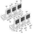
- FIG. 1is a diagram showing an arrangement of an in-flight monitor system 1 provided in an aircraft in the first embodiment.
- a plurality of seats 500 for seating passengers (users)are provided.
- An in-flight monitor 200 and a cradle 300are provided at predetermined positions on the back side of the back of the seat 500.
- Each of the in-flight monitors 200has the same configuration.
- Each of the cradle 300has the same configuration.
- the cradle 300includes a storage unit 311.
- the cradle 300can store the remote control 400 in the storage unit 311.
- Each of the remote controllers 400has the same configuration.
- the in-flight monitor 200 and the cradle 300are visible to the passenger at a position facing the passenger sitting on the seat 500 behind the seat 500 on which the in-flight monitor 200 and the cradle 300 are mounted. Installed.
- the passengeroperates the touch panel (described later) or the remote control 400 of the in-flight monitor 200 provided in the front seat 500 while sitting on the seat 500, and also watches the video displayed on the in-flight monitor 200. It is possible to receive various in-flight services.
- the passengercan operate the remote controller 400 in a state where the remote controller 400 is stored in the cradle 300 or in a state where the remote controller 400 is removed from the cradle 300.
- An aircraftis an example of transportation equipment.
- the remote controlis an example of a first terminal.
- the cradleis an example of the second terminal.
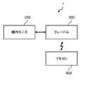
- FIG. 2is a block diagram showing the configuration of the in-flight monitor system 1.
- the in-flight monitor system 1includes an in-flight monitor 200, a cradle 300, and a remote controller 400.
- the in-flight monitor 200can reproduce the content distributed from the server device.
- the in-flight monitor 200is wired to the cradle 300, and can communicate with the cradle 300 by wire.
- the cradle 300can wirelessly communicate with the remote control 400 using an infrared signal. That is, the in-flight monitor 200 can receive the operation content from the remote controller 400 via the cradle 300 and can perform processing corresponding to the received operation content.
- the in-flight monitor systemis an example of a communication system.
- FIG. 3is a diagram showing the positional relationship between the cradle 300 and the remote controller 400.
- FIG. 3shows a state in which the remote controller 400 is stored in the storage unit 311 of the cradle 300.
- the cradle 300includes a magnetic sensor 304, an infrared receiver 305, and an infrared transmitter 306.
- the cradle 300includes a storage unit 311 for storing the remote control 400 and an IR (InfraRed) window 313.
- the storage unit 311has a concave shape capable of holding the remote control 400 and includes a bottom surface 312 and a side surface 315.
- the magnetic sensor 304is disposed inside the bottom surface 312.
- the IR window 313is provided on the side surface 315.
- the IR window 313is formed of a material that transmits infrared rays.
- the infrared receiving unit 305is disposed inside the IR window 313 and can receive infrared signals from the outside through the IR window 313.
- the infrared transmission unit 306is disposed inside the IR window 313 and can transmit infrared signals to the outside through the IR window 313.
- the infrared receiving unit 305is an example of a second light receiving unit.
- the infrared transmission unit 306is an example of a second light emitting unit.
- the remote control 400includes an infrared receiver 405, an infrared transmitter 406, a magnet 409, an operation unit 411, and an IR window 413.
- Magnet 409is arranged inside bottom surface 412 of remote controller 400.
- the operation unit 411is an input interface such as a push button or a touch panel, and is provided on the upper surface 414 of the remote control 400.
- IR window 413is provided on side surface 415 of remote controller 400.
- the IR window 413is formed of a material that transmits infrared rays.
- the infrared receiving unit 405is disposed inside the IR window 413 and can receive infrared signals from the outside through the IR window 413.
- the infrared transmitter 406is disposed inside the IR window 413 and can transmit infrared signals to the outside through the IR window 413.
- the infrared receiving unit 405is an example of a first light receiving unit.
- the infrared transmission unit 406is an example of a first light emitting unit.
- the magnet 409is an example of a magnetized magnetic body.
- the bottom surface 312 of the cradle 300 and the bottom surface 412 of the remote control 400face each other.
- the magnetic sensor 304 of the cradle 300 and the magnet 409 of the remote control 400face each other with the bottom surface 312 of the cradle and the bottom surface 412 of the remote control 400 interposed therebetween.
- the bottom surface 312 of the cradle and the bottom surface 412 of the remote controller 400are each formed of a nonmagnetic material such as resin. Therefore, the magnetic sensor 304 can detect the magnetic field generated by the magnet 409 in a state where the remote control 400 is housed in the cradle 300.
- the IR window 313 of the cradle 300 and the IR window 413 of the remote control 400face each other.
- the infrared reception unit 305 of the cradle 300 and the infrared transmission unit 406 of the remote control 400face each other with the IR window 313 of the cradle 300 and the IR window 413 of the remote control 400 interposed therebetween.
- the infrared receiver 305can receive the infrared signal transmitted by the infrared transmitter 406.
- the infrared transmission unit 306 of the cradle 300 and the infrared reception unit 405 of the remote control 400face each other with the IR window 313 of the cradle 300 and the IR window 413 of the remote control 400 interposed therebetween.
- the infrared receiver 405can receive the infrared signal transmitted by the infrared transmitter 306.
- FIG. 4is a block diagram showing an electrical configuration of the in-flight monitor 200.
- the in-flight monitor 200includes a network interface (I / F) 201, a CPU 202, a memory 203, a touch panel 204, a display 206, and a USB interface (I / F) 207.
- the network interface 201is an interface for the CPU 202 to communicate with an external device (not shown) such as a server device via a network cable.
- the CPU 202executes a program stored in the memory 203 and performs various calculations and information processing.
- the CPU 202can read from and write to the memory 203. Further, the CPU 202 communicates with the server device via the network interface 201. Further, the CPU 202 communicates with the cradle 300 via the USB interface 207.
- the memory 203stores a program executed by the CPU 202 and a calculation result of the CPU 202.
- the memory 203is configured by a flash memory or a RAM.
- the touch panel 204is disposed on the surface of the display 206.
- information indicating the position touched by the touch panel 204is transmitted to the CPU 202.
- the CPU 202performs control according to this information, the passenger can perform an intuitive operation.
- the display 206displays various contents in accordance with instructions from the CPU 202.
- the USB interface 207is an interface for the CPU 202 to communicate with the cradle 300 via a communication cable.
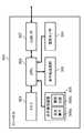
- FIG. 5is a block diagram showing an electrical configuration of the cradle 300.
- the cradle 300includes a CPU 302, a memory 303, a magnetic sensor 304, an infrared receiving unit 305, an infrared transmitting unit 306, and a USB interface (I / F) 307.
- the CPU 302executes a program stored in the memory 303 to perform various calculations and information processing.
- the CPU 302can read from and write to the memory 303.
- the CPU 302communicates with the in-flight monitor 200 via the USB interface 307.
- the CPU 302causes the infrared transmission unit 306 to emit light based on the signal to be transmitted. More specifically, the CPU 302 modulates a signal to be transmitted and causes the infrared transmitter 306 to emit light according to the modulated signal.
- the CPU 302is an example of a second controller.
- the memory 303stores a program executed by the CPU 302, a calculation result of the CPU 302, and an ID of the remote controller 400.
- the ID of the remote controller 400is information for specifying one remote controller 400 from among the plurality of remote controllers 400.
- the ID of the remote controlis an example of first specific information.
- the memory 303is configured by a flash memory or a RAM.
- the memory 303is an example of a second memory.
- the magnetic sensor 304detects the magnetic field at the position where the magnetic sensor 304 is placed. When the magnetic field exceeds a certain threshold value, the magnetic sensor 304 transmits a detection signal indicating that the threshold value has been exceeded to the CPU 302.
- the magnetic sensor 304detects the magnetic field of the magnet 409 provided in the remote controller 400 and transmits a detection signal. That is, when the remote controller 400 is housed in the cradle 300, the magnetic sensor 304 transmits a detection signal.
- the magnetic sensor 304is an example of a second storage sensor.
- the infrared receiving unit 305includes a light receiving element 305a and a demodulation circuit 305b.
- the light receiving element 305areceives an infrared signal from the remote controller 400.
- the demodulation circuit 305bdemodulates the received signal from the infrared signal and transmits it to the CPU 302.
- the infrared transmission unit 306is an LED that emits infrared light.
- the infrared transmission unit 306emits an infrared signal based on the signal modulated by the CPU 302.
- the USB interface 307is an interface for the CPU 302 to communicate with the in-flight monitor 200 via a communication cable.
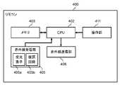
- FIG. 6is a block diagram showing an electrical configuration of the remote control 400.
- the remote control 400includes a CPU 402, a memory 403, an infrared receiver 405, an infrared transmitter 406, and an operation unit 411.
- the CPU 402executes programs stored in the memory 403 and performs various calculations and information processing.
- the CPU 402can read from and write to the memory 403.
- the CPU 402causes the infrared transmission unit 406 to emit light based on the signal to be transmitted. More specifically, the CPU 402 modulates a signal to be transmitted and causes the infrared transmission unit 406 to emit light according to the modulated signal.
- the CPU 402is an example of a first controller.
- the memory 403stores a program executed by the CPU 402, a calculation result of the CPU 402, and an ID of the remote controller 400.
- the memory 403is configured by a flash memory or a RAM.
- the memory 403is an example of a first memory.
- the infrared receiving unit 405includes a light receiving element 405a and a demodulation circuit 405b.
- the light receiving element 405areceives the infrared signal from the cradle 300.
- the demodulation circuit 405bdemodulates the received signal from the infrared signal and transmits it to the CPU 402.
- the infrared transmission unit 406is an LED (light emitting element) that emits infrared light.
- the infrared transmission unit 406emits an infrared signal based on the signal modulated by the CPU 402.
- the operation unit 411is an input interface such as a push button or a touch panel. When the passenger operates the operation unit 411, a signal corresponding to the operation is transmitted to the CPU 402.
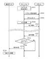
- FIG. 7is a sequence diagram for explaining the pairing and the operation after pairing in the in-flight monitor system 1.
- the cradle 300When a passenger or a passenger stores the remote control 400 in the storage unit 311 of the cradle 300, the cradle 300 performs pairing with the stored remote control 400. Once pairing is performed, the cradle 300 thereafter transmits a reception signal from the paired remote control 400 to the in-flight monitor 200, while ignoring reception signals from other than the paired remote control 400.
- the operation of the in-flight monitor system 1will be described with reference to FIG.
- the pairing operation between the cradle 300 and the remote controller 400will be described.
- the CPU 302 of the cradle 300monitors the storage of the remote control 400. Specifically, the CPU 302 stands by until a detection signal is received from the magnetic sensor 304.
- the magnetic sensor 304provided in the cradle 300 and the magnet 409 provided in the remote control 400 approach each other. Then, the magnetic sensor 304 detects the magnetic field of the magnet 409 and outputs a detection signal.
- CPU302detects accommodation of remote control 400 (S701).
- the CPU 302 of the cradle 300receives the detection signal, it determines that the remote control 400 is stored.
- the CPU 302transmits a pairing request signal to the remote controller 400 using the infrared transmission unit 306 (S702).
- the pairing request signalis a signal including information indicating that the cradle 300 requests the remote controller 400 to perform a pairing operation.
- the CPU 402 of the remote control 400monitors the pairing request signal from the cradle 300 by the infrared receiving unit 405.
- the CPU 402transmits its own ID (ID of the remote controller 400) to the cradle 300 using the infrared transmission unit 406 (S703).
- the CPU 302 of the cradle 300receives the ID of the remote controller 400 by the infrared receiving unit 305 and stores it in the memory 303 (S705).
- the cradle 300transmits a processing completion notification to the remote control 400 using the infrared transmission unit 306 (S707). With the above operation, the pairing operation is completed.
- the remote control 400may be stored in the cradle 300, or the passenger takes out the remote control 400 from the cradle 300, and the IR window 413 (infrared transmission unit 406) of the remote control 400 is placed in the IR of the cradle 300. It may be in a state of being held toward the window 313 (infrared receiving unit 305), that is, in a state where infrared communication is possible with each other.
- the CPU 402 of the remote control 400transmits operation information using the infrared transmission unit 406 (S711).
- the operation informationincludes the ID of the remote controller 400 and the operation content (for example, information indicating that the enter button has been pressed).
- operation informationincluding the ID of the remote control 400 and the operation content indicating which button is pressed is transmitted using the infrared transmission unit 406. ,Send.
- the CPU 302 of the cradle 300monitors reception of operation information from the remote control 400 by the infrared receiving unit 305.
- the CPU 302compares the ID of the remote control 400 included in the operation information with the ID of the remote control 400 stored in the memory 303 (S712).
- the cradle 300determines that the received operation information is transmitted from the paired remote control 400.
- the CPU 302performs control according to the operation information. Specifically, the CPU 302 transmits the operation content included in the operation information to the in-flight monitor 200 using the USB interface 307 (S713).
- the CPU 202 of the in-flight monitor 200performs processing corresponding to the operation content (S714). If the IDs are different as a result of the comparison (No in S712), the cradle 300 determines that the received operation information is not transmitted from the paired remote control 400, and ignores the operation information.
- the in-flight monitor 200can perform various operations corresponding to only the operation of the remote controller 400 paired with the connected cradle 300.
- in-flight monitor system 1performs infrared communication between remote controller 400 and cradle 300 including storage unit 311 in which remote controller 400 can be stored.
- the remote control 400includes an infrared transmission unit 406 that emits infrared light, an infrared reception unit 405 that receives infrared light, a memory 403 that stores an ID of the remote control 400 for identifying the remote control 400, and an infrared reception unit 405.
- a CPU 402that causes the infrared transmitter 406 to emit light based on the ID of the remote controller 400 when it is determined that the signal obtained by demodulating the infrared light received by the receiver includes a pairing request signal.
- the cradle 300includes a magnetic sensor 304 that detects that the remote controller 400 is stored in the storage unit, an infrared transmission unit 306 that emits infrared light, an infrared reception unit 305 that receives infrared light, a memory 303, CPU302.
- CPU 302causes infrared transmission unit 306 to emit light based on the pairing request signal in response to magnetic sensor 304 detecting the storage of remote control 400.
- the CPU 302stores the ID of the remote control 400 acquired by demodulating the infrared light received by the infrared receiving unit 305 in the memory 303, and the operation information obtained by demodulating the infrared light received by the infrared receiving unit 305 is stored in the memory.
- the operation contentis transmitted to the in-flight monitor 200.
- the remote controller 400 and the cradle 300are paired only by storing the remote controller 400 in the cradle 300. Thereafter, the paired remote controller 400 performs operations on the in-flight monitor 200 connected to the cradle 300. It becomes possible. That is, the in-flight monitor system of the present embodiment is effective for easily performing pairing.
- the second embodimentwill be described below with reference to FIGS.
- the in-flight monitor system 2 according to the second embodimentis different from the in-flight monitor system 1 according to the first embodiment in that a remote controller 420 that takes two states of an active state and a sleep state is provided instead of the remote controller 400.
- the same numbersare assigned to the same configurations as those in the first embodiment, and detailed description is omitted.
- FIG. 8is a diagram illustrating the positional relationship between the respective parts of the cradle 300 and the remote controller 420.
- the remote controller 420includes an infrared receiver 405, an infrared transmitter 406, a magnet 409, an operation unit 411, an IR transistor 408, and an IR window 413.
- the IR transistor 408is a phototransistor that is turned on by receiving infrared light.
- the IR transistor 408is disposed inside the IR window 413 and can receive infrared light from the outside through the IR window 413.
- the infrared transmission unit 306 of the cradle 300sandwiches the infrared reception unit 405 and the IR transistor 408 of the remote control 420, the IR window 313 of the cradle 300, and the IR window 413 of the remote control 420. opposite.
- FIG. 9is a block diagram showing an electrical configuration of the remote controller 420.
- the remote controller 420includes a CPU 402, a memory 403, an infrared receiver 405, an infrared transmitter 406, and an IR transistor 408.
- the IR transistor 408detects the light emission of the infrared transmission unit 306 of the cradle 300 and transmits a detection signal to the CPU 402.
- the infrared receiving unit 405can receive infrared light (infrared signal), demodulate it, and extract a received signal.
- the infrared receiver 405can also demodulate a signal in a higher frequency band than the IR transistor 408, but has a higher standby power than the IR transistor 408.
- the IR transistor 408can only receive signals in a lower frequency band than the infrared receiver 405. For this reason, it is not suitable for receiving an infrared signal whose signal is modulated, but the standby power is lower than that of the infrared receiver 405.
- FIG. 10is a sequence diagram for explaining the pairing and the operation after pairing in the in-flight monitor system 2.
- the cradle 300performs pairing by changing the stored remote control 420 from the sleep state to the active state.
- the remote controller 420transitions to a sleep state.
- the remote controller 420transitions from the sleep state to the active state when there is a button operation or the like, and transitions from the active state to the sleep state after the operation is completed.
- the remote controller 420is in a sleep state before pairing.
- the sleep stateis a state in which the CPU 402 is not operating and power is not supplied to each unit of the remote controller 420 including the infrared receiving unit 405 and the unit is not operating.
- the IR transistor 408is turned on when it receives infrared light, and can transmit a detection signal to the CPU 402.
- the operation unit 411can transmit a signal corresponding to the operation to the CPU 402 when operated by a passenger.
- the active stateis a state in which the CPU 402 is operating and power is supplied to each part of the remote control 400.
- the CPU 402alone has two states: a sleep state in which almost no power is supplied and is not operating, and an active state in which power is supplied and each unit is operating.
- the magnetic sensor 304 provided in the cradle 300 and the magnet 409 provided in the remote controller 420approach each other. Then, the magnetic sensor 304 detects the magnetic field of the magnet 409 and outputs a detection signal. As a result, the CPU 302 detects the storage of the remote controller 420 (S701). The CPU 302 of the cradle 300 emits (transmits) a return request signal to the remote controller 420 using the infrared transmission unit 306 (S721).
- the return request signalmay be any signal as long as it is infrared light that can be detected by the IR transistor 408.
- the return request signalmay be a signal that emits light at a constant intensity for a predetermined time.
- the IR transistor 408receives infrared light (return request signal) and transmits a detection signal to the CPU 402.
- the CPU 402transitions from the sleep state to the active state.
- the CPU 402causes the remote controller 420 to transition from the sleep state to the active state by further starting the operation of each unit of the remote controller 420 (S722).
- the remote controller 420transmits a return signal indicating the transition to the active state to the cradle 300 using the infrared transmission unit 406 (S723). Since steps S702 to S707 are the same as those in the first embodiment, description thereof is omitted. If no operation is performed on the remote controller 420 for a certain period of time after pairing is completed, the CPU 402 causes the remote controller 420 to transition to the sleep state (S708).
- remote controller 420includes IR transistor 408 that has lower standby power than infrared receiver 405 and receives infrared light.
- the CPU 302 of the cradle 300causes the infrared transmitter 306 to emit light based on the return request signal in response to the magnetic sensor 304 detecting the storage of the remote controller 420, and then causes the infrared transmitter 306 to operate based on the pairing request signal. Make it emit light.
- the CPU 402 of the remote control 400transitions to the active state and resumes operation in response to the IR transistor 408 receiving infrared light when in the sleep state.
- the remote controller 420even when the remote controller 420 is in the sleep state, when it is stored in the cradle 300, it transitions to the active state and pairing is performed. That is, the in-flight monitor system 2 of the present embodiment is effective for easily performing pairing.
- the remote controller 420transitions to the active state and transmits operation information. In the sleep state, since each unit including the infrared receiving unit 405 is not operating, standby power can be reduced.
- the third embodimentwill be described below with reference to FIGS.
- the in-flight monitor system 3 according to the third embodimentis different from the in-flight monitor system 2 according to the second embodiment in that a remote controller 430 including a magnetic sensor 404 is provided instead of the remote controller 420, and a cradle including a magnet is used instead of the cradle 300. 330.
- the same numbersare assigned to configurations similar to those in the second embodiment, and detailed description is omitted.
- FIG. 11is a diagram showing the positional relationship between the respective parts of the cradle 330 and the remote controller 430.
- the cradle 330includes a magnetic sensor 304, an infrared receiver 305, an infrared transmitter 306, and a magnet 309.
- the cradle 330includes a storage unit 311 for storing the remote controller 430 and an IR window 313.
- the storage unit 311includes a bottom surface 312 and a side surface 315.
- the remote controller 430includes a magnetic sensor 404, an infrared receiver 405, an infrared transmitter 406, a magnet 409, an IR transistor 408, and an IR window 413.
- the magnetic sensor 404is disposed inside the bottom surface 412.
- the magnet 309is disposed inside the bottom surface 312 of the cradle 330.
- the magnet 309 of the cradle 330 and the magnetic sensor 404 of the remote controller 430face each other with the bottom surface 312 of the cradle and the bottom surface 412 of the remote controller 430 interposed therebetween.
- the magnetic sensor 404can detect the magnetic field generated by the magnet 309.
- the magnetic sensor 404is disposed at a distance or orientation that does not detect the magnetic field of the magnet 409.
- the magnetic sensor 304is disposed at a distance or orientation that does not detect the magnetic field of the magnet 309.
- FIG. 12is a block diagram showing an electrical configuration of the remote controller 430.
- the remote controller 430includes a CPU 402, a memory 403, a magnetic sensor 404, an infrared receiver 405, an infrared transmitter 406, an IR transistor 408, an AND gate 410, and an operation unit 411.
- the magnetic sensor 404detects the magnetic field at the position where the magnetic sensor 404 is placed. When the magnetic field exceeds a certain threshold value, the magnetic sensor 404 transmits a detection signal indicating that the threshold value has been exceeded to the CPU 402.
- the magnetic sensor 404detects the magnetic field of the magnet 309 provided in the cradle 330 and transmits a detection signal.
- the magnetic sensor 404is an example of a first storage sensor.
- the IR transistor 408is an example of a detection element that detects infrared light.
- the IR transistor 408detects light emission of the infrared transmission unit 306 of the cradle 330.
- FIG. 10is a sequence diagram for explaining the pairing and the operation after pairing in the in-flight monitor system 3.
- the operation of the in-flight monitor system 3will be described with reference to FIG.
- step S722is the same as that of the second embodiment, only step S722 will be described.
- the IR transistor 408receives infrared light (return request signal) and transmits a detection signal.
- the magnetic sensor 404detects a magnetic field generated by the magnet 309 of the cradle 330 and transmits a detection signal.
- the AND gate 410transmits a detection signal to the CPU 402.
- the CPU 402receives the detection signal from the AND gate 410, the CPU 402 transitions from the sleep state to the active state.
- the CPU 402causes the remote controller 430 to transition from the sleep state to the active state by further starting the operation of each unit of the remote controller 430 (S722).
- the remote control 430includes the magnetic sensor 404 that detects that the remote control 430 is stored in the storage unit 311.
- the magnetic sensor 404detects that the remote controller 430 is housed, and the IR transistor 408 receives the infrared light to transition to the active state and resume operation.
- the in-flight monitor system 3 of the present embodimentis effective for easy pairing. Further, since the conditions when the cradle 330 is housed in the active state are both the detection by the magnetic sensor 404 and the detection by the IR transistor 408, the possibility of erroneous detection can be further reduced.
- an in-flight monitoring system in an aircraftis shown as an example, but this system may be a wireless communication system in transportation equipment such as a bullet train or a bus, which includes a cradle and a remote control.
- the configurationhas been described in which the cradle detects the storage of the remote control and starts the pairing operation.
- the in-flight monitor system 1may be configured such that the remote controller detects the storage in the cradle and starts the pairing operation.
- the configuration and operation related to pairing of the magnetic sensor, infrared transmission unit, infrared reception unit, etc. in the cradle and remote controlare opposite to each other, and the remote control detects storage by the magnetic sensor and sends a pairing request signal to the cradle. It may be configured to.
- the configuration using the ID of the remote controller as information for confirming that they are paired with each otherhas been described.
- the cradle IDmay be used as this information.
- the cradle IDis transmitted at the same time as or after the cradle transmits a pairing request signal to the remote controller.
- the remote controllerstores the cradle ID in the memory and then sends a completion notification to the cradle.
- the cradlemay transmit the cradle ID to the remote controller in response to receiving the pairing request signal.
- the cradle IDis an example of second specifying information.
- the configurationhas been described in which the remote controller (first terminal) detects that the remote controller (first terminal) is stored in the storage unit of the cradle (second terminal) and performs pairing.
- the conditions for pairingare not limited to this, and the first terminal and the second terminal can be engaged with each other by a mechanical holding mechanism or magnetic force, and the second terminal detects the engagement instead of the storage sensor.
- the structure provided with a combined sensormay be sufficient.
- the method of detecting storage using magnetismis not limited to this, and a magnetic sensor and a magnet are arranged on one side, and a magnetic body such as an iron plate is arranged on the other side so as to face the magnetic sensor and the magnet. Good.
- the storage sensoris not limited to a magnetic sensor, and a mechanical switch that is switched on / off by storage or an electrical switch that is switched on / off by storage may be used.
- the cradle and the infrared receiver of the remote controllerhave been described as having a light receiving element and a demodulation circuit, respectively.
- the infrared receiving unitmay include only the light receiving element, and the CPU may demodulate based on the infrared signal received by the light receiving element.
- the infrared transmission unitmay further include a modulation circuit, and modulate the signal sent from the CPU to cause the LED to emit light.
- the configurationhas been described in which the remote control transitions to the sleep state if there is no operation for a certain period of time in the active state.
- the remote controllermay transition to the sleep state immediately after completing the necessary operation in the active state.
- the remote controlcan also perform pairing and post-pairing operations from the active state. For example, if the remote control receives a return request signal in the active state, it transmits the return signal to the cradle as it is. When the operation unit 411 is operated in the active state, operation information corresponding to the operation is transmitted to the cradle as it is.
- the configuration in which the in-flight monitor and the cradle are housed in separate housings and connected via the USB I / Fhas been described.
- the in-machine monitor and the cradlemay be integrated into a single unit.
- the cradleis described as being provided on the back side of the backrest of the aircraft seat.
- the arrangement of the cradleis not limited to this.
- the cradlemay be configured to be provided on the upper surface or the side surface of the armrest of the seat behind the seat on which the in-flight monitor is provided.
- an in-flight monitor systemincluding an in-flight monitor, a cradle, and a remote control
- the communication systemdoes not necessarily include an in-flight monitor.
- the device connected to the cradle via the interfaceis not limited to the in-flight monitor, but may be a projector, headphones, or the like that can express video and sound.
- the communication systemmay include the first terminal described with the remote control as an example and the second terminal described with the cradle as an example.
- the communication system according to the present disclosureis effective for easy pairing and can be applied to a wireless communication system in an aircraft, a train, or the like.
- In-machine monitor system 200In-machine monitor 201 Network interface 202 CPU 203 Memory 204 Touch Panel 206 Display 207 USB Interface 300, 330 Cradle 302 CPU 303 Memory 304 Magnetic Sensor 305 Infrared Receiver 305a Light Receiving Element 305b Demodulator 306 Infrared Transmitter 307 USB Interface 309 Magnet 311 Storage Unit 312 Bottom 313 IR Window 315 Side 400, 420, 430 Remote Controller 402 CPU 403 Memory 404 Magnetic sensor 405 Infrared receiver 405a Light receiving element 405b Demodulator circuit 406 Infrared transmitter 408 IR transistor 409 Magnet 410 AND gate 411 Operation unit 412 Bottom 413 IR window 414 Upper surface 415 Side surface 500 Seat
Landscapes
- Engineering & Computer Science (AREA)
- Physics & Mathematics (AREA)
- Computer Networks & Wireless Communication (AREA)
- Aviation & Aerospace Engineering (AREA)
- General Physics & Mathematics (AREA)
- Signal Processing (AREA)
- Multimedia (AREA)
- Human Computer Interaction (AREA)
- Electromagnetism (AREA)
- Selective Calling Equipment (AREA)
Abstract
Description
Translated fromJapanese本開示は、2つの機器の間でペアリングを行って無線通信を行う通信システムに関する。The present disclosure relates to a communication system that performs wireless communication by performing pairing between two devices.
特許文献1は、操作対象装置に信号を送信可能な操作側第1通信部と、操作対象装置と信号を送受信可能な操作側第2通信部と、操作対象装置にペアリングの開始を指示するペアリング開始信号を、操作側第1通信部を介して送信するペアリング開始手段と、操作側第2通信部を介してペアリングを行う操作側ペアリング実行手段とを備える遠隔操作装置を開示する。この構成により、ユーザに負担をかけずに容易にペアリングを行うことができる。Japanese Patent Laid-Open No. 2004-26883 instructs an operation-side first communication unit capable of transmitting a signal to an operation target device, an operation-side second communication unit capable of transmitting / receiving a signal to / from the operation target device, and an operation target device to start pairing. Disclosed is a remote control device including a pairing start unit that transmits a pairing start signal via the operation side first communication unit and an operation side pairing execution unit that performs pairing via the operation side second communication unit. To do. With this configuration, pairing can be easily performed without placing a burden on the user.
本開示は、容易にペアリングを行うことが可能な通信システムを提供する。This disclosure provides a communication system that can be easily paired.
本開示における第1の態様に係る通信システムは、第1端末と、第1端末を収納可能な収納部を備えるとともに第1端末との間で無線通信を行う第2端末と、を備える。第1端末は、赤外光を発光する第1発光部と、赤外光を受光する第1受光部と、第1端末を特定するための第1特定情報を記憶する第1メモリと、第1コントローラと、を備える。第1コントローラは、第1受光部が受光する赤外光を復調した信号がペアリング要求信号を含むと判断したときに、第1特定情報に基づいて第1発光部を発光させる。第2端末は、収納部に第1端末が収納されたことを検出する第2収納センサと、赤外光を発光する第2発光部と、赤外光を受光する第2受光部と、第2メモリと、第2コントローラと、を備える。第2コントローラは、第2収納センサが第1端末の収納を検出するのに応じて、ペアリング要求信号に基づいて第2発光部を発光させ、第2受光部が受光する赤外光を復調した第1特定情報を第2メモリに記憶させ、第2受光部が受光する赤外光を復調した情報が第2メモリに記憶した第1特定情報を含むと判断したときに、情報に応じた制御を行う。The communication system according to the first aspect of the present disclosure includes a first terminal and a second terminal that includes a storage unit that can store the first terminal and performs wireless communication with the first terminal. The first terminal includes a first light emitting unit that emits infrared light, a first light receiving unit that receives infrared light, a first memory that stores first identification information for identifying the first terminal, 1 controller. When the first controller determines that the signal obtained by demodulating the infrared light received by the first light receiving unit includes a pairing request signal, the first controller causes the first light emitting unit to emit light based on the first specific information. The second terminal includes a second storage sensor that detects that the first terminal is stored in the storage unit, a second light emitting unit that emits infrared light, a second light receiving unit that receives infrared light, Two memories and a second controller. The second controller emits the second light-emitting unit based on the pairing request signal and demodulates the infrared light received by the second light-receiving unit in response to the second storage sensor detecting the storage of the first terminal. The first specific information is stored in the second memory, and when it is determined that the information obtained by demodulating the infrared light received by the second light receiving unit includes the first specific information stored in the second memory Take control.
本開示における第2の態様に係る通信システムは、第1端末と、第1端末と無線通信を行い、第1端末と係合可能な第2端末と、を備える。第1端末は、赤外光を発光する第1発光部と、赤外光を受光する第1受光部と、第1端末を特定するための第1特定情報を記憶する第1メモリと、第1コントローラと、を備える。第1コントローラは、第1受光部が受光する赤外光を復調した信号がペアリング要求信号を含むと判断したときに、第1特定情報に基づいて第1発光部を発光させる。第2端末は、第1端末と係合したことを検出する第2係合センサと、赤外光を発光する第2発光部と、赤外光を受光する第2受光部と、第2メモリと、第2コントローラと、を備える。第2コントローラは、第2収納センサが第1端末の収納を検出するのに応じて、ペアリング要求信号に基づいて第2発光部を発光させ、第2受光部が受光する赤外光を復調した第1特定情報を第2メモリに記憶させ、第2受光部が受光する赤外光を復調した情報が第2メモリに記憶した第1特定情報を含むと判断したときに、情報に応じた制御を行う。The communication system according to the second aspect of the present disclosure includes a first terminal, and a second terminal that performs wireless communication with the first terminal and can be engaged with the first terminal. The first terminal includes a first light emitting unit that emits infrared light, a first light receiving unit that receives infrared light, a first memory that stores first identification information for identifying the first terminal, 1 controller. When the first controller determines that the signal obtained by demodulating the infrared light received by the first light receiving unit includes a pairing request signal, the first controller causes the first light emitting unit to emit light based on the first specific information. The second terminal includes a second engagement sensor that detects engagement with the first terminal, a second light emitting unit that emits infrared light, a second light receiving unit that receives infrared light, and a second memory. And a second controller. The second controller emits the second light-emitting unit based on the pairing request signal and demodulates the infrared light received by the second light-receiving unit in response to the second storage sensor detecting the storage of the first terminal. The first specific information is stored in the second memory, and when it is determined that the information obtained by demodulating the infrared light received by the second light receiving unit includes the first specific information stored in the second memory Take control.
本開示における通信システムは、容易にペアリングを行うのに有効である。The communication system according to the present disclosure is effective for easy pairing.
以下、適宜図面を参照しながら、実施の形態を詳細に説明する。但し、必要以上に詳細な説明は省略する場合がある。例えば、既によく知られた事項の詳細説明や実質的に同一の構成に対する重複説明を省略する場合がある。これは、以下の説明が不必要に冗長になるのを避け、当業者の理解を容易にするためである。Hereinafter, embodiments will be described in detail with reference to the drawings as appropriate. However, more detailed description than necessary may be omitted. For example, detailed descriptions of already well-known matters and repeated descriptions for substantially the same configuration may be omitted. This is to avoid the following description from becoming unnecessarily redundant and to facilitate understanding by those skilled in the art.
なお、添付図面および以下の説明は、当業者が本開示を十分に理解するために、提供されるのであって、これらにより請求の範囲に記載の主題を限定することは意図されていない。The accompanying drawings and the following description are provided for those skilled in the art to fully understand the present disclosure, and are not intended to limit the claimed subject matter.
(実施の形態1)
以下、図1~図7を用いて、実施の形態1を説明する。(Embodiment 1)
The first embodiment will be described below with reference to FIGS.
[1-1 構成]
図1は、実施の形態1における航空機内に設けられた機内モニタシステム1の配置を示す図である。航空機内には、乗客(ユーザ)が着座するための複数の座席500が設けられている。座席500の背もたれの背面側の所定位置には、機内モニタ200とクレードル300とがそれぞれ設けられる。機内モニタ200の各々は、同じ構成を備えている。クレードル300の各々は、同じ構成を備えている。クレードル300は、収納部311を備える。クレードル300は、収納部311にリモコン400を収納することができる。リモコン400の各々は、同じ構成を備えている。[1-1 Configuration]
FIG. 1 is a diagram showing an arrangement of an in-
図1に示すように、機内モニタ200とクレードル300とは、機内モニタ200とクレードル300とが装着された座席500の後ろの座席500に着座する乗客と対向する位置に、乗客から視認可能なように設置される。乗客は、座席500に着座した状態で、前の座席500に設けられた機内モニタ200のタッチパネル(後述)またはリモコン400を操作し、また、機内モニタ200に表示される映像を鑑賞することで、各種の機内サービスを受けることが可能である。乗客は、リモコン400をクレードル300に収納した状態で、又はクレードル300から取り出した状態で、操作することができる。なお、航空機は、輸送機器の一例である。リモコンは、第1端末の一例である。クレードルは、第2端末の一例である。As shown in FIG. 1, the in-
図2は、機内モニタシステム1の構成を示すブロック図である。機内モニタシステム1は、機内モニタ200とクレードル300とリモコン400とを備える。FIG. 2 is a block diagram showing the configuration of the in-
機内モニタ200は、サーバ装置から配信されたコンテンツの再生等が可能である。機内モニタ200は、クレードル300と有線接続されており、クレードル300と有線による通信が可能である。また、クレードル300は、リモコン400と赤外線信号による無線通信が可能である。すなわち、機内モニタ200は、クレードル300を介してリモコン400からの操作内容を受信し、受信した操作内容に対応した処理を行うことが可能である。機内モニタシステムは、通信システムの一例である。The in-
図3は、クレードル300及びリモコン400の各部の位置関係を示す図である。図3は、リモコン400をクレードル300の収納部311に収納した状態を示している。FIG. 3 is a diagram showing the positional relationship between the
クレードル300は、磁気センサ304と、赤外線受信部305と、赤外線送信部306とを備える。クレードル300は、リモコン400を収納するための収納部311と、IR(InfraRed)窓313とを備える。収納部311は、リモコン400を保持可能な凹部形状をしており、底面312及び側面315を備える。磁気センサ304は、底面312の内側に配置される。IR窓313は、側面315に設けられる。IR窓313は、赤外線を透過する材料で形成される。赤外線受信部305は、IR窓313の内側に配置され、IR窓313を通して外部からの赤外線信号の受信が可能である。赤外線送信部306は、IR窓313の内側に配置され、IR窓313を通して外部への赤外線信号の送信が可能である。赤外線受信部305は、第2受光部の一例である。赤外線送信部306は、第2発光部の一例である。The
リモコン400は、赤外線受信部405と、赤外線送信部406と、磁石409と、操作部411と、IR窓413とを備える。磁石409は、リモコン400の底面412の内側に配置される。操作部411は、押しボタンやタッチパネル等の入力インターフェースであり、リモコン400の上面414に設けられる。IR窓413は、リモコン400の側面415に設けられる。IR窓413は、赤外線を透過する材料で形成される。赤外線受信部405は、IR窓413の内側に配置され、IR窓413を通して外部からの赤外線信号の受信が可能である。赤外線送信部406は、IR窓413の内側に配置され、IR窓413を通して外部への赤外線信号の送信が可能である。赤外線受信部405は、第1受光部の一例である。赤外線送信部406は、第1発光部の一例である。磁石409は、磁化された磁性体の一例である。The
クレードル300にリモコン400を収納した状態において、クレードル300の底面312とリモコン400の底面412とは対向する。クレードル300にリモコン400を収納した状態において、クレードル300の磁気センサ304とリモコン400の磁石409とは、クレードルの底面312とリモコン400の底面412とを挟んで対向する。ここで、クレードルの底面312及びリモコン400の底面412は、各々樹脂等の非磁性体で形成されている。したがって磁気センサ304は、クレードル300にリモコン400を収納した状態において、磁石409が発生する磁界を検出可能である。In the state where the
クレードル300にリモコン400を収納した状態において、クレードル300のIR窓313とリモコン400のIR窓413とは対向する。クレードル300にリモコン400を収納した状態において、クレードル300の赤外線受信部305とリモコン400の赤外線送信部406とは、クレードル300のIR窓313とリモコン400のIR窓413とを挟んで対向する。このとき、赤外線受信部305は、赤外線送信部406が送信する赤外線信号を受信可能である。クレードル300にリモコン400を収納した状態において、クレードル300の赤外線送信部306とリモコン400の赤外線受信部405とは、クレードル300のIR窓313とリモコン400のIR窓413とを挟んで対向する。このとき、赤外線受信部405は、赤外線送信部306が送信する赤外線信号を受信可能である。In the state where the
図4は、機内モニタ200の電気的構成を示すブロック図である。機内モニタ200は、ネットワークインターフェース(I/F)201と、CPU202と、メモリ203と、タッチパネル204と、ディスプレイ206と、USBインターフェース(I/F)207とを備える。ネットワークインターフェース201は、CPU202が、サーバ装置等の外部装置(図示せず)とネットワークケーブルを介して通信を実施するためのインターフェースである。FIG. 4 is a block diagram showing an electrical configuration of the in-
CPU202は、メモリ203に格納されたプログラムを実行し、各種演算や情報処理を行う。CPU202は、メモリ203に対して読み出しと書き込みが可能である。また、CPU202は、ネットワークインターフェース201を介してサーバ装置との通信を行う。また、CPU202は、USBインターフェース207を介してクレードル300との通信を行う。The
メモリ203は、CPU202が実行するプログラムや、CPU202の演算結果を格納する。メモリ203は、フラッシュメモリやRAMで構成される。The
タッチパネル204は、ディスプレイ206の表面に配置される。乗客がディスプレイ206上の表示に触れると、タッチパネル204が触れた位置を示す情報をCPU202に伝送する。CPU202がこの情報に応じて制御を行うことで、乗客は直感的な操作が可能である。ディスプレイ206はCPU202からの命令に従い、各種コンテンツを表示する。The
USBインターフェース207は、CPU202が、クレードル300と通信ケーブルを介して通信を実施するためのインターフェースである。The
図5は、クレードル300の電気的構成を示すブロック図である。クレードル300は、CPU302と、メモリ303と、磁気センサ304と、赤外線受信部305と、赤外線送信部306と、USBインターフェース(I/F)307とを備える。FIG. 5 is a block diagram showing an electrical configuration of the
CPU302は、メモリ303に格納されたプログラムを実行し、各種演算や情報処理を行う。CPU302は、メモリ303に対して読み出しと書き込みが可能である。また、CPU302は、USBインターフェース307を介して機内モニタ200との通信を行う。CPU302は、赤外線送信部306から信号を送信する場合、送信したい信号に基づいて赤外線送信部306を発光させる。より具体的には、CPU302は、送信したい信号を変調し、変調した信号に従って赤外線送信部306を発光させる。CPU302は、第2コントローラの一例である。The
メモリ303は、CPU302が実行するプログラムや、CPU302の演算結果や、リモコン400のIDを格納する。リモコン400のIDは、複数のリモコン400の中から1つのリモコン400を特定するための情報である。リモコンのIDは、第1特定情報の一例である。メモリ303は、フラッシュメモリやRAMで構成される。メモリ303は、第2メモリの一例である。The
磁気センサ304は、磁気センサ304が置かれた位置における磁界を検出する。磁気センサ304は、磁界がある特定の閾値を超えた場合、閾値を超えたことを示す検出信号をCPU302に送信する。磁気センサ304は、リモコン400に具備されている磁石409の磁界を検出して検出信号を送信する。すなわち、リモコン400をクレードル300に収納すると、磁気センサ304は検出信号を送信する。磁気センサ304は、第2収納センサの一例である。The
赤外線受信部305は、受光素子305aと復調回路305bとを備える。受光素子305aは、リモコン400からの赤外線信号を受光する。復調回路305bは、赤外線信号から受信信号を復調し、CPU302に送信する。The
赤外線送信部306は、赤外光を発光するLEDである。赤外線送信部306は、CPU302で変調された信号に基づき、赤外線信号を発光する。The
USBインターフェース307は、CPU302が、機内モニタ200と通信ケーブルを介して通信を実施するためのインターフェースである。The
図6は、リモコン400の電気的構成を示すブロック図である。リモコン400は、CPU402と、メモリ403と、赤外線受信部405と、赤外線送信部406と、操作部411とを備える。FIG. 6 is a block diagram showing an electrical configuration of the
CPU402は、メモリ403に格納されたプログラムを実行し、各種演算や情報処理を行う。CPU402は、メモリ403に対して読み出しと書き込みが可能である。CPU402は、赤外線送信部406から信号を送信する場合、送信したい信号に基づいて赤外線送信部406を発光させる。より具体的には、CPU402は、送信したい信号を変調し、変調した信号に従って赤外線送信部406を発光させる。CPU402は、第1コントローラの一例である。The
メモリ403は、CPU402が実行するプログラムや、CPU402の演算結果や、リモコン400のIDを格納する。メモリ403は、フラッシュメモリやRAMで構成される。メモリ403は、第1メモリの一例である。The
赤外線受信部405は、受光素子405aと復調回路405bとを備える。受光素子405aは、クレードル300からの赤外線信号を受光する。復調回路405bは、赤外線信号から受信信号を復調し、CPU402に送信する。The
赤外線送信部406は、赤外光を発光するLED(発光素子)である。赤外線送信部406は、CPU402で変調された信号に基づき、赤外線信号を発光する。The
操作部411は、押しボタンやタッチパネル等の入力インターフェースである。乗客が操作部411を操作すると、操作に応じた信号がCPU402に送信される。The
[1-2 動作]
以上のように構成された機内モニタシステム1について、その動作を以下で説明する。図7は、機内モニタシステム1におけるペアリング及びペアリング後の動作を説明するためのシーケンス図である。[1-2 Operation]
The operation of the on-
乗客や乗員が、クレードル300の収納部311にリモコン400を収納すると、クレードル300は、収納したリモコン400とペアリングを行う。一旦ペアリングが行われると、以後、クレードル300は、ペアリングされたリモコン400からの受信信号を機内モニタ200に送信する一方、ペアリングされたリモコン400以外からの受信信号を無視する。以下、このときの機内モニタシステム1の動作について、図7を参照し説明する。When a passenger or a passenger stores the
[1-2-1 ペアリングの実施]
クレードル300とリモコン400とのペアリングの動作について説明する。クレードル300のCPU302は、リモコン400の収納を監視している。具体的には、CPU302は、磁気センサ304から検出信号を受信するまで待機している。リモコン400がクレードルに収納されると、クレードル300に具備されている磁気センサ304と、リモコン400に具備されている磁石409とが接近する。すると、磁気センサ304が磁石409の磁界を検出して、検出信号を出力する。これにより、CPU302は、リモコン400の収納を検出する(S701)。クレードル300のCPU302は、検出信号を受信すると、リモコン400が収納されたと判断する。そしてCPU302は、赤外線送信部306を用いて、リモコン400にペアリング要求信号を送信する(S702)。ペアリング要求信号とは、クレードル300がリモコン400に対してペアリング動作を行うよう要求することを示す情報を含む信号である。[1-2-1 Pairing]
The pairing operation between the
リモコン400のCPU402は、赤外線受信部405により、クレードル300からのペアリング要求信号を監視している。CPU402は、ペアリング要求信号を受信すると、赤外線送信部406を用いて、自身のID(リモコン400のID)をクレードル300に送信する(S703)。クレードル300のCPU302は、赤外線受信部305により、リモコン400のIDを受信して、メモリ303に記憶する(S705)。クレードル300は、記憶が完了すると、赤外線送信部306を用いて、リモコン400に処理完了通知を送信する(S707)。以上の動作により、ペアリング動作が完了する。The
[1-2-2 ペアリング後の処理]
次に、ペアリング後の機内モニタシステム1、すなわち機内モニタ200、クレードル300及びリモコン400の動作について説明する。以下の説明では、リモコン400はクレードル300に収納された状態であってもよいし、乗客がリモコン400をクレードル300から取り出して、リモコン400のIR窓413(赤外線送信部406)をクレードル300のIR窓313(赤外線受信部305)に向けて保持した状態、すなわち互いに赤外線通信が可能な状態であってもよい。[1-2-2 Processing after pairing]
Next, operations of the in-
リモコン400のCPU402は、乗客や乗員によって操作部411の操作が行われた場合、赤外線送信部406を用いて、操作情報を送信する(S711)。操作情報は、リモコン400のIDと、操作内容(例えば、決定ボタンが押されたことを示す情報)とを含む。例えば、乗客や乗員がリモコン400の操作部411に含まれるボタンを押した場合、リモコン400のIDとどのボタンが押されたかを示す操作内容とを含む操作情報を、赤外線送信部406を用いて、送信する。When the
クレードル300のCPU302は、赤外線受信部305により、リモコン400からの操作情報の受信を監視している。CPU302は、赤外線受信部305により操作情報を受信すると、操作情報に含まれるリモコン400のIDと、メモリ303に記憶されているリモコン400のIDと比較する(S712)。The
クレードル300は、比較の結果、IDが同じであった場合(S712においてYes)、受信した操作情報がペアリングされたリモコン400から送信されたものであると判断する。そしてCPU302は、この操作情報に応じた制御を行う。具体的には、CPU302は、操作情報に含まれる操作内容を、USBインターフェース307を用いて、機内モニタ200に送信する(S713)。機内モニタ200のCPU202は、USBインターフェース207を用いて、クレードル300から操作内容を受信すると、操作内容に対応する処理を実施する(S714)。クレードル300は、比較の結果、IDが異なる場合(S712においてNo)、受信した操作情報がペアリングされたリモコン400から送信されたものではないと判断し、その操作情報を無視する。If the IDs are the same as a result of the comparison (Yes in S712), the
以下、この動作を繰り返すことにより、機内モニタ200は、接続されたクレードル300とペアリングされたリモコン400の操作のみに対応して各種動作を行うことができる。Hereinafter, by repeating this operation, the in-
[1-3 効果等]
以上のように、本実施の形態において、機内モニタシステム1は、リモコン400と、リモコン400を収納可能な収納部311を備えるクレードル300との赤外線通信を行う。リモコン400は、赤外光を発光する赤外線送信部406と、赤外光を受光する赤外線受信部405と、リモコン400を特定するためのリモコン400のIDを記憶するメモリ403と、赤外線受信部405が受光する赤外光を復調した信号がペアリング要求信号を含むと判断したときに、リモコン400のIDに基づいて赤外線送信部406を発光させるCPU402と、を備える。クレードル300は、収納部にリモコン400が収納されたことを検出する磁気センサ304と、赤外光を発光する赤外線送信部306と、赤外光を受光する赤外線受信部305と、メモリ303と、CPU302と、を備える。CPU302は、磁気センサ304がリモコン400の収納を検出するのに応じて、ペアリング要求信号に基づいて赤外線送信部306を発光させる。そして、CPU302は、赤外線受信部305が受光する赤外光を復調することにより取得したリモコン400のIDをメモリ303に記憶させ、赤外線受信部305が受光する赤外光を復調した操作情報がメモリ303に記憶したリモコン400のIDを含むと判断したときに、機内モニタ200に操作内容を送信する。[1-3 Effects, etc.]
As described above, in this embodiment, in-
これにより、リモコン400がクレードル300に収納されるだけで、リモコン400とクレードル300とのペアリングが行われ、以後、ペアリングされたリモコン400によって、クレードル300と接続された機内モニタ200に対する操作が可能となる。すなわち、本実施の形態の機内モニタシステムは、容易にペアリングを行うのに有効である。As a result, the
(実施の形態2)
以下、図8~図10を用いて、実施の形態2を説明する。実施の形態2の機内モニタシステム2が実施の形態1の機内モニタシステム1と異なるところは、リモコン400に替えて、アクティブ状態及びスリープ状態の2つの状態を取るリモコン420を有することである。実施の形態1と同様の構成については同じ番号を付与し、詳細な説明を省略する。(Embodiment 2)
The second embodiment will be described below with reference to FIGS. The in-flight monitor system 2 according to the second embodiment is different from the in-
[2-1 構成]
図8は、クレードル300及びリモコン420の各部の位置関係を示す図である。リモコン420は、赤外線受信部405と、赤外線送信部406と、磁石409と、操作部411と、IRトランジスタ408と、IR窓413とを備える。[2-1 Configuration]
FIG. 8 is a diagram illustrating the positional relationship between the respective parts of the
IRトランジスタ408は、赤外光を受光することによりオンになるフォトトランジスタである。IRトランジスタ408は、IR窓413の内側に配置され、IR窓413を通して外部からの赤外光の受光が可能である。The
クレードル300にリモコン420を収納した状態において、クレードル300の赤外線送信部306は、リモコン420の赤外線受信部405及びIRトランジスタ408と、クレードル300のIR窓313とリモコン420のIR窓413とを挟んで対向する。In a state where the
図9は、リモコン420の電気的構成を示すブロック図である。リモコン420は、CPU402と、メモリ403と、赤外線受信部405と、赤外線送信部406と、IRトランジスタ408とを備える。FIG. 9 is a block diagram showing an electrical configuration of the
IRトランジスタ408は、クレードル300の赤外線送信部306の発光を検出し、検出信号をCPU402に送信する。ここで、赤外線受信部405とIRトランジスタ408との違いについて説明する。赤外線受信部405は、赤外光(赤外線信号)を受光し、これを復調して受信信号を取り出すことができる。赤外線受信部405は、IRトランジスタ408と比較してより高い周波数帯域の信号も復調することができるが、IRトランジスタ408よりも待機電力が高い。IRトランジスタ408は、赤外線受信部405と比較して、より低い周波数帯域の信号しか受光できない。このため、信号が変調された赤外線信号の受光には適さないが、赤外線受信部405よりも待機電力が低い。The
[2-2 動作]
以上のように構成された機内モニタシステム2について、その動作を以下で説明する。図10は、機内モニタシステム2におけるペアリング及びペアリング後の動作を説明するためのシーケンス図である。[2-2 Operation]
The operation of the on-board monitor system 2 configured as described above will be described below. FIG. 10 is a sequence diagram for explaining the pairing and the operation after pairing in the in-flight monitor system 2.
まず、実施の形態2の機内モニタシステム2の動作の概要について説明する。乗客や乗員が、クレードル300にリモコン420を収納すると、クレードル300は、収納したリモコン420をスリープ状態からアクティブ状態へと遷移させて、ペアリングを行う。ペアリングが完了すると、リモコン420は、スリープ状態に遷移する。First, an outline of the operation of the in-flight monitor system 2 of the second embodiment will be described. When a passenger or a passenger stores the
リモコン420は、ボタン操作等があった場合は、スリープ状態からアクティブ状態に遷移し、動作完了後、アクティブ状態からスリープ状態に遷移する。The
以下、このときの機内モニタシステム2の動作について図10を参照し説明する。Hereinafter, the operation of the in-flight monitor system 2 at this time will be described with reference to FIG.
[2-2-1 ペアリングの実施]
クレードル300とリモコン420とのペアリングの動作について説明する。リモコン420は、ペアリング前は、スリープ状態となっている。スリープ状態とは、CPU402が動作しておらず、かつ、赤外線受信部405を含むリモコン420の各部に電力が供給されず動作していない状態である。ただしスリープ状態においてもIRトランジスタ408は、赤外光を受光するとオンになり、CPU402に検出信号を送信することが可能である。また、スリープ状態においても操作部411は、乗客によって操作されると、操作に応じた信号をCPU402に送信可能である。アクティブ状態とは、CPU402が動作しており、かつ、リモコン400の各部に電力が供給されており動作している状態である。また、CPU402単体についても、電力がほとんど供給されず動作していないスリープ状態と、電力が供給され各部が動作しているアクティブ状態の2つの状態をとるものとする。[2-2-1 Pairing]
The pairing operation between the
リモコン420がクレードル300に収納されると、クレードル300に具備されている磁気センサ304と、リモコン420に具備されている磁石409とが接近する。すると、磁気センサ304が磁石409の磁界を検出して、検出信号を出力する。これにより、CPU302は、リモコン420の収納を検出する(S701)。クレードル300のCPU302は、赤外線送信部306を用いて、リモコン420に復帰要求信号を発光(送信)する(S721)。復帰要求信号は、IRトランジスタ408が検出可能な赤外光であればどのような信号でもよい。例えば復帰要求信号は、一定強度で一定時間発光する信号であってもよい。When the
IRトランジスタ408は、赤外光(復帰要求信号)を受光して検出信号をCPU402に送信する。CPU402は、この検出信号を受信すると、スリープ状態からアクティブ状態に遷移する。CPU402は、さらにリモコン420の各部の動作を開始させることにより、リモコン420をスリープ状態からアクティブ状態に遷移させる(S722)。リモコン420は、アクティブ状態に遷移したこと示す復帰信号を、赤外線送信部406を用いて、クレードル300に送信する(S723)。以降、ステップS702~S707は実施の形態1と同様であるため、説明を省略する。CPU402は、ペアリング完了後、一定時間リモコン420に対する操作が行われなければ、リモコン420をスリープ状態に遷移させる(S708)。The
[2-2-2 ペアリング後の処理]
ペアリング後の、機内モニタ200、クレードル300及びリモコン420の動作について説明する。ここでは、リモコン420はペアリング完了後にスリープ状態となっているものとする。乗客や乗員が操作部411を操作すると、操作に応じた信号をCPU402に送信する。リモコン420のCPU402は、この信号を受信すると、CPU402自身がアクティブ状態となった後に、リモコン420の状態を、スリープ状態からアクティブ状態に遷移させる(S710)。以降、ステップS711~S714は、実施の形態1と同様であるため、説明を省略する。リモコン420のCPU402は、ステップS711における操作情報の送信後、一定時間リモコン420に対する操作が行われなければ、リモコン420をスリープ状態に遷移させる(S715)。[2-2-2 Processing after pairing]
Operations of the in-
[2-3 効果等]
以上のように、本実施の形態の機内モニタシステム2において、リモコン420は、赤外線受信部405よりも待機電力が低く、赤外光を受光するIRトランジスタ408を備える。クレードル300のCPU302は、磁気センサ304がリモコン420の収納を検出するのに応じて、復帰要求信号に基づいて赤外線送信部306を発光させた後、ペアリング要求信号に基づいて赤外線送信部306を発光させる。リモコン400のCPU402は、スリープ状態であるときにIRトランジスタ408が赤外光を受光するのに応じてアクティブ状態に遷移して動作を再開する。[2-3 Effects, etc.]
As described above, in remote monitor system 2 of the present embodiment,
これにより、リモコン420がスリープ状態となっているときであっても、クレードル300に収納されるとアクティブ状態に遷移してペアリングが行われる。すなわち、本実施の形態の機内モニタシステム2は、容易にペアリングを行うのに有効である。また、リモコン420は、スリープ状態であっても操作部411の操作が行われると、アクティブ状態に遷移して操作情報の送信を行う。スリープ状態においては、赤外線受信部405を含む各部が動作していないため、待機電力を低減することができる。Thus, even when the
(実施の形態3)
以下、図11~図12を用いて、実施の形態3を説明する。実施の形態3の機内モニタシステム3が実施の形態2の機内モニタシステム2と異なるところは、リモコン420に替えて磁気センサ404を備えるリモコン430を有し、クレードル300に替えて、磁石を備えるクレードル330を有するところである。実施の形態2と同様の構成については同じ番号を付与し、詳細な説明を省略する。(Embodiment 3)
The third embodiment will be described below with reference to FIGS. The in-flight monitor system 3 according to the third embodiment is different from the in-flight monitor system 2 according to the second embodiment in that a
[3-1 構成]
図11は、クレードル330及びリモコン430の各部の位置関係を示す図である。クレードル330は、磁気センサ304と、赤外線受信部305と、赤外線送信部306と、磁石309とを備える。クレードル330は、リモコン430を収納するための収納部311と、IR窓313とを備える。収納部311は、底面312及び側面315を備える。[3-1 Configuration]
FIG. 11 is a diagram showing the positional relationship between the respective parts of the
リモコン430は、磁気センサ404と、赤外線受信部405と、赤外線送信部406と、磁石409と、IRトランジスタ408と、IR窓413とを備える。The
磁気センサ404は、底面412の内側に配置される。磁石309は、クレードル330の底面312の内側に配置される。クレードル330にリモコン430を収納した状態において、クレードル330の磁石309とリモコン430の磁気センサ404とは、クレードルの底面312とリモコン430の底面412とを挟んで対向する。このとき、磁気センサ404は、磁石309が発生する磁界を検出可能である。ここで、磁気センサ404は、磁石409の磁界を検出しないような距離、または向きに配置されている。同様に、磁気センサ304は、磁石309の磁界を検出しないような距離、または向きに配置されている。The
図12は、リモコン430の電気的構成を示すブロック図である。リモコン430は、CPU402と、メモリ403と、磁気センサ404と、赤外線受信部405と、赤外線送信部406と、IRトランジスタ408と、ANDゲート410と、操作部411とを備える。FIG. 12 is a block diagram showing an electrical configuration of the
磁気センサ404は、磁気センサ404が置かれた位置における磁界を検出する。磁気センサ404は、磁界がある特定の閾値を超えた場合、閾値を超えたことを示す検出信号をCPU402に送信する。磁気センサ404は、クレードル330に具備されている磁石309の磁界を検出して検出信号を送信する。磁気センサ404は、第1収納センサの一例である。IRトランジスタ408は、赤外光を検出する検出素子の一例である。IRトランジスタ408は、クレードル330の赤外線送信部306の発光を検出する。磁気センサ404による磁界の検出と、IRトランジスタ408による発光の検出とが同時に起こった場合、ANDゲート410の出力が変化し、検出信号をCPU402に送信する。The
[3-2 動作]
以上のように構成された機内モニタシステム3について、その動作を以下で説明する。図10は、機内モニタシステム3におけるペアリング及びペアリング後の動作を説明するためのシーケンス図である。以下、このときの機内モニタシステム3の動作について図10を参照し説明する。[3-2 Operation]
The operation of the on-board monitor system 3 configured as described above will be described below. FIG. 10 is a sequence diagram for explaining the pairing and the operation after pairing in the in-flight monitor system 3. Hereinafter, the operation of the in-flight monitor system 3 will be described with reference to FIG.
[3-2-1 ペアリングの実施]
クレードル330とリモコン430とのペアリングの動作について説明する。ステップS722以外は実施の形態2と同様のため、ステップS722のみ説明する。[3-2-1 Pairing]
The pairing operation between the
IRトランジスタ408は、赤外光(復帰要求信号)を受光して検出信号を送信する。磁気センサ404は、クレードル330の磁石309による磁界を検出して検出信号を送信する。磁気センサ404と、IRトランジスタ408とが同時に検出信号を送信するときに、ANDゲート410は、CPU402に検出信号を送信する。CPU402は、ANDゲート410からの検出信号を受信すると、スリープ状態からアクティブ状態に遷移する。CPU402は、さらにリモコン430の各部の動作を開始させることにより、リモコン430をスリープ状態からアクティブ状態に遷移させる(S722)。The
[3-2-2 ペアリング後の処理]
ペアリング後の処理は、実施の形態2と同様のため、説明を省略する。[3-2-2 Processing after pairing]
Since the processing after pairing is the same as that of the second embodiment, description thereof is omitted.
[3-3 効果等]
以上のように、本実施の形態の機内モニタシステム3において、リモコン430は、収納部311にリモコン430が収納されたことを検出する磁気センサ404を備える。リモコン400のCPU402は、スリープ状態であるときに磁気センサ404がリモコン430の収納を検出し且つIRトランジスタ408が赤外光を受光するのに応じてアクティブ状態に遷移して動作を再開する。[3-3 Effects, etc.]
As described above, in the in-flight monitor system 3 according to the present embodiment, the
これにより、リモコン430がスリープ状態になっているときであっても、クレードル330に収納されるとアクティブ状態に遷移してペアリングが行われる。すなわち、本実施の形態の機内モニタシステム3は、容易にペアリングを行うのに有効である。また、クレードル330に収納されてアクティブ状態となるときの条件が、磁気センサ404による検出及びIRトランジスタ408による検出の両方であるため、誤検出の可能性をより低減できる。Thereby, even when the
(他の実施の形態)
以上のように、本出願において開示する技術の例示として、上記実施の形態を説明した。しかしながら、本開示における技術は、これに限定されず、適宜、変更、置き換え、付加、省略などを行った実施の形態にも適用可能である。また、上記実施の形態で説明した各構成要素を組み合わせて、新たな実施の形態とすることも可能である。そこで、以下、他の実施の形態を例示する。(Other embodiments)
As described above, the embodiment has been described as an example of the technique disclosed in the present application. However, the technology in the present disclosure is not limited to this, and can also be applied to an embodiment in which changes, replacements, additions, omissions, and the like are appropriately performed. Moreover, it is also possible to combine each component demonstrated in the said embodiment and it can also be set as a new embodiment. Therefore, other embodiments will be exemplified below.
上記実施の形態では、一例として航空機内の機内モニタシステムを示したが、本システムは、クレードルとリモコンとを備える、新幹線、バス等の輸送機器内の無線通信システムであっても良い。In the above embodiment, an in-flight monitoring system in an aircraft is shown as an example, but this system may be a wireless communication system in transportation equipment such as a bullet train or a bus, which includes a cradle and a remote control.
上記実施の形態では、クレードルがリモコンの収納を検出してペアリングの動作を開始する構成について説明した。機内モニタシステム1は、リモコンがクレードルへの収納を検出してペアリングの動作を開始する構成としてもよい。すなわち、クレードル及びリモコンにおける磁気センサ、赤外線送信部、赤外線受信部等のペアリングに関する構成及び動作が互いに逆となっており、リモコンが磁気センサにより収納を検出し、ペアリング要求信号をクレードルに送信する構成であってもよい。In the above embodiment, the configuration has been described in which the cradle detects the storage of the remote control and starts the pairing operation. The in-
上記実施の形態では、互いにペアリングされていることを確認するための情報として、リモコンのIDを使用する構成について説明した。この情報としては、クレードルのIDを使用するようにしてもよい。例えばクレードルがリモコンにペアリング要求信号を送信するのと同時に、またはその後に続いて、クレードルのIDを送信する。リモコンは、クレードルのIDをメモリに記憶してから完了通知をクレードルに送信する。また上記のようにリモコンからペアリング要求信号を送信する場合は、クレードルは、ペアリング要求信号を受信するのに応じてクレードルのIDをリモコンに送信するようにすればよい。クレードルのIDは第2特定情報の一例である。In the above embodiment, the configuration using the ID of the remote controller as information for confirming that they are paired with each other has been described. The cradle ID may be used as this information. For example, the cradle ID is transmitted at the same time as or after the cradle transmits a pairing request signal to the remote controller. The remote controller stores the cradle ID in the memory and then sends a completion notification to the cradle. Further, when the pairing request signal is transmitted from the remote controller as described above, the cradle may transmit the cradle ID to the remote controller in response to receiving the pairing request signal. The cradle ID is an example of second specifying information.
上記実施の形態では、リモコン(第1端末)がクレードル(第2端末)の収納部に収納されることを検出してペアリングを行う構成について説明した。ペアリングを行う条件はこれに限らず、第1端末と第2端末が機械的な保持機構、または磁力等により係合可能であり、収納センサの代わりに第2端末が係合を検出する係合センサを備える構成であってもよい。In the above embodiment, the configuration has been described in which the remote controller (first terminal) detects that the remote controller (first terminal) is stored in the storage unit of the cradle (second terminal) and performs pairing. The conditions for pairing are not limited to this, and the first terminal and the second terminal can be engaged with each other by a mechanical holding mechanism or magnetic force, and the second terminal detects the engagement instead of the storage sensor. The structure provided with a combined sensor may be sufficient.
上記実施の形態では、クレードル及びリモコンのうち一方が磁気センサを備え、他方が磁石を備え、これらにより収納を検出する構成について説明した。磁気を用いて収納を検出する方法についてはこれに限らず、一方に磁気センサ及び磁石を配置し、他方に、磁気センサ及び磁石と対向するように鉄板等の磁性体を配置するようにしてもよい。このようにすることで、クレードルにリモコンが収納、すなわち各々が互いに接近すると、磁石が対向する磁性体を磁化するため、磁気センサが磁化された磁性体による磁界を検出する。これにより、収納を検出することができる。In the above embodiment, the configuration in which one of the cradle and the remote controller is provided with a magnetic sensor and the other is provided with a magnet to detect storage by these. The method of detecting storage using magnetism is not limited to this, and a magnetic sensor and a magnet are arranged on one side, and a magnetic body such as an iron plate is arranged on the other side so as to face the magnetic sensor and the magnet. Good. By doing so, when the remote control is housed in the cradle, that is, when the respective units come close to each other, the magnets magnetize the opposing magnetic bodies, so the magnetic sensor detects the magnetic field by the magnetized magnetic bodies. Thereby, storage can be detected.
上記実施の形態では、収納センサとして磁気センサを用いる構成について説明した。収納センサとしては、磁気センサに限らず、収納によりオン/オフが切り替わる機械的なスイッチや、収納によりオン/オフが切り替わる電気的なスイッチを用いてもよい。In the above embodiment, the configuration using the magnetic sensor as the storage sensor has been described. The storage sensor is not limited to a magnetic sensor, and a mechanical switch that is switched on / off by storage or an electrical switch that is switched on / off by storage may be used.
上記実施の形態では、クレードル及びリモコンの赤外線受信部は、それぞれ受光素子と復調回路とを備える構成について説明した。赤外線受信部は、受光素子のみを備え、受光素子が受信した赤外線信号に基づいてCPUが復調する構成としてもよい。In the above embodiment, the cradle and the infrared receiver of the remote controller have been described as having a light receiving element and a demodulation circuit, respectively. The infrared receiving unit may include only the light receiving element, and the CPU may demodulate based on the infrared signal received by the light receiving element.
上記実施の形態では、クレードル及びリモコンの赤外線送信部は、LEDを備える構成について説明した。赤外線送信部は、さらに変調回路を備え、CPUから送られてくる信号を変調してLEDを発光させる構成としてもよい。In the above-described embodiment, the configuration in which the cradle and the infrared transmission unit of the remote controller include LEDs has been described. The infrared transmission unit may further include a modulation circuit, and modulate the signal sent from the CPU to cause the LED to emit light.
上記実施の形態2、3では、リモコンが、アクティブ状態において一定時間操作がなければスリープ状態に遷移する構成について説明した。リモコンは、アクティブ状態において必要な動作を完了した後で、すみやかにスリープ状態に遷移するようにしてもよい。In the second and third embodiments, the configuration has been described in which the remote control transitions to the sleep state if there is no operation for a certain period of time in the active state. The remote controller may transition to the sleep state immediately after completing the necessary operation in the active state.
上記実施の形態2、3では、スリープ状態からペアリングやペアリング後の動作を行うときについて説明した。リモコンは、アクティブ状態からペアリングやペアリング後の動作を行うことももちろん可能である。例えば、リモコンはアクティブ状態において復帰要求信号を受信した場合は、そのまま復帰信号をクレードルに送信する。また、アクティブ状態において操作部411を操作された場合は、そのまま操作に応じた操作情報をクレードルに送信する。In the second and third embodiments, the case where the pairing or the operation after the pairing is performed from the sleep state has been described. Of course, the remote control can also perform pairing and post-pairing operations from the active state. For example, if the remote control receives a return request signal in the active state, it transmits the return signal to the cradle as it is. When the
上記実施の形態では、機内モニタとクレードルとが別の筐体に収められ、USB I/Fを介して接続される構成について説明した。機内モニタとクレードルとは一体の筐体に収められる、一体型の構成としてもよい。In the above embodiment, the configuration in which the in-flight monitor and the cradle are housed in separate housings and connected via the USB I / F has been described. The in-machine monitor and the cradle may be integrated into a single unit.
上記実施の形態では、クレードルは航空機の座席の背もたれの背面側に設けられる構成について説明した。クレードルの配置はこれに限らず、例えば機内モニタが設けられる座席の1つ後ろの座席の肘掛けの上面または側面に設けられる構成としてもよい。In the above embodiment, the cradle is described as being provided on the back side of the backrest of the aircraft seat. The arrangement of the cradle is not limited to this. For example, the cradle may be configured to be provided on the upper surface or the side surface of the armrest of the seat behind the seat on which the in-flight monitor is provided.
上記実施の形態では、通信システムの一例として、機内モニタ、クレードルおよびリモコンを備える機内モニタシステムを説明したが、通信システムとしては、機内モニタを必ずしも備える必要はない。例えば、クレードルとインターフェースを介して接続される装置は機内モニタに限らず、映像、音を表現できるプロジェクタ、ヘッドフォン等でもよい。即ち、通信システムとしては、リモコンを例に説明した第1端末およびクレードルを例に説明した第2端末を備えればよい。In the above embodiment, an in-flight monitor system including an in-flight monitor, a cradle, and a remote control has been described as an example of a communication system. However, the communication system does not necessarily include an in-flight monitor. For example, the device connected to the cradle via the interface is not limited to the in-flight monitor, but may be a projector, headphones, or the like that can express video and sound. In other words, the communication system may include the first terminal described with the remote control as an example and the second terminal described with the cradle as an example.
以上のように、本開示における技術の例示として、実施の形態を説明した。そのために、添付図面および詳細な説明を提供した。As described above, the embodiments have been described as examples of the technology in the present disclosure. For this purpose, the accompanying drawings and detailed description are provided.
したがって、添付図面および詳細な説明に記載された構成要素の中には、課題解決のために必須な構成要素だけでなく、上記技術を例示するために、課題解決のためには必須でない構成要素も含まれ得る。そのため、それらの必須ではない構成要素が添付図面や詳細な説明に記載されていることをもって、直ちに、それらの必須ではない構成要素が必須であるとの認定をするべきではない。Accordingly, among the components described in the accompanying drawings and the detailed description, not only the components essential for solving the problem, but also the components not essential for solving the problem in order to illustrate the above technique. May also be included. Therefore, it should not be immediately recognized that these non-essential components are essential as those non-essential components are described in the accompanying drawings and detailed description.
また、上述の実施の形態は、本開示における技術を例示するためのものであるから、請求の範囲またはその均等の範囲において種々の変更、置き換え、付加、省略などを行うことができる。In addition, since the above-described embodiment is for illustrating the technique in the present disclosure, various modifications, replacements, additions, omissions, and the like can be performed within the scope of the claims or an equivalent scope thereof.
本開示における通信システムは、容易にペアリングを行うのに有効であり、航空機や列車等における無線通信システムに適用可能である。The communication system according to the present disclosure is effective for easy pairing and can be applied to a wireless communication system in an aircraft, a train, or the like.
1,2,3 機内モニタシステム
200 機内モニタ
201 ネットワークインターフェース
202 CPU
203 メモリ
204 タッチパネル
206 ディスプレイ
207 USBインターフェース
300,330 クレードル
302 CPU
303 メモリ
304 磁気センサ
305 赤外線受信部
305a 受光素子
305b 復調回路
306 赤外線送信部
307 USBインターフェース
309 磁石
311 収納部
312 底面
313 IR窓
315 側面
400,420,430 リモコン
402 CPU
403 メモリ
404 磁気センサ
405 赤外線受信部
405a 受光素子
405b 復調回路
406 赤外線送信部
408 IRトランジスタ
409 磁石
410 ANDゲート
411 操作部
412 底面
413 IR窓
414 上面
415 側面
500 座席1, 2, 3 In-
203
303
403
Claims (6)
Translated fromJapanese前記第1端末を収納可能な収納部を備えるとともに前記第1端末との間で無線通信を行う第2端末と、を備え、
前記第1端末は、
赤外光を発光する第1発光部と、
赤外光を受光する第1受光部と、
前記第1端末を特定するための第1特定情報を記憶する第1メモリと、
前記第1受光部が受光する前記赤外光を復調した信号がペアリング要求信号を含むと判断したときに、前記第1特定情報に基づいて前記第1発光部を発光させる第1コントローラと、を備え、
前記第2端末は、
前記収納部に前記第1端末が収納されたことを検出する第2収納センサと、
赤外光を発光する第2発光部と、
赤外光を受光する第2受光部と、
第2メモリと、
前記第2収納センサが前記第1端末の収納を検出するのに応じて、前記ペアリング要求信号に基づいて前記第2発光部を発光させ、前記第2受光部が受光する赤外光を復調した前記第1特定情報を前記第2メモリに記憶させ、前記第2受光部が受光する赤外光を復調した情報が前記第2メモリに記憶した前記第1特定情報を含むと判断したときに、前記情報に応じた制御を行う第2コントローラと、を備える、
通信システム。A first terminal;
A second terminal that includes a storage unit that can store the first terminal and performs wireless communication with the first terminal;
The first terminal is
A first light emitting unit that emits infrared light;
A first light receiving portion for receiving infrared light;
A first memory for storing first specifying information for specifying the first terminal;
A first controller that causes the first light emitting unit to emit light based on the first specific information when it is determined that a signal obtained by demodulating the infrared light received by the first light receiving unit includes a pairing request signal; With
The second terminal is
A second storage sensor for detecting that the first terminal is stored in the storage unit;
A second light emitting unit that emits infrared light;
A second light receiving portion for receiving infrared light;
A second memory;
In response to the second storage sensor detecting the storage of the first terminal, the second light emitting unit emits light based on the pairing request signal, and the infrared light received by the second light receiving unit is demodulated. The first specific information is stored in the second memory, and when it is determined that the information obtained by demodulating the infrared light received by the second light receiving unit includes the first specific information stored in the second memory A second controller that performs control according to the information,
Communications system.
前記第2コントローラは、前記第2収納センサが前記第1端末の収納を検出するのに応じて、復帰要求信号に基づいて前記第2発光部を発光させた後で、前記ペアリング要求信号に基づいて前記第2発光部を発光させ、
前記第1コントローラは、スリープ状態であるときに前記検出素子が前記赤外光を検出するのに応じて動作を再開する、
請求項1記載の通信システム。The first terminal includes a detection element that has lower standby power than the first light receiving unit and detects infrared light,
In response to the second storage sensor detecting the storage of the first terminal, the second controller causes the second light emitting unit to emit light based on a return request signal, and then sends the pairing request signal to the pairing request signal. And causing the second light emitting unit to emit light based on
The first controller resumes operation in response to the detection element detecting the infrared light when in a sleep state.
The communication system according to claim 1.
前記第1コントローラは、スリープ状態であるときに前記第1収納センサが前記第1端末の収納を検出し且つ前記検出素子が前記赤外光を検出するのに応じて動作を再開する、
請求項2記載の通信システム。The first terminal includes a first storage sensor that detects that the first terminal is stored in the storage unit;
The first controller resumes operation in response to the first storage sensor detecting the storage of the first terminal and the detection element detecting the infrared light when in a sleep state.
The communication system according to claim 2.
前記第1端末と無線通信を行い、前記第1端末と係合可能な第2端末と、を備え、
前記第1端末は、
赤外光を発光する第1発光部と、
赤外光を受光する第1受光部と、
前記第1端末を特定するための第1特定情報を記憶する第1メモリと、
前記第1受光部が受光する前記赤外光を復調した信号がペアリング要求信号を含むと判断したときに、前記第1特定情報に基づいて前記第1発光部を発光させる第1コントローラと、を備え、
前記第2端末は、
前記第1端末と係合したことを検出する第2係合センサと、
赤外光を発光する第2発光部と、
赤外光を受光する第2受光部と、
第2メモリと、
前記第2収納センサが前記第1端末の収納を検出するのに応じて、前記ペアリング要求信号に基づいて前記第2発光部を発光させ、前記第2受光部が受光する赤外光を復調した前記第1特定情報を前記第2メモリに記憶させ、前記第2受光部が受光する赤外光を復調した情報が前記第2メモリに記憶した前記第1特定情報を含むと判断したときに、前記情報に応じた制御を行う第2コントローラと、を備える、
通信システム。A first terminal;
A second terminal that performs wireless communication with the first terminal and is engageable with the first terminal;
The first terminal is
A first light emitting unit that emits infrared light;
A first light receiving portion for receiving infrared light;
A first memory for storing first specifying information for specifying the first terminal;
A first controller that causes the first light emitting unit to emit light based on the first specific information when it is determined that a signal obtained by demodulating the infrared light received by the first light receiving unit includes a pairing request signal; With
The second terminal is
A second engagement sensor for detecting engagement with the first terminal;
A second light emitting unit that emits infrared light;
A second light receiving portion for receiving infrared light;
A second memory;
In response to the second storage sensor detecting the storage of the first terminal, the second light emitting unit emits light based on the pairing request signal, and the infrared light received by the second light receiving unit is demodulated. The first specific information is stored in the second memory, and when it is determined that the information obtained by demodulating the infrared light received by the second light receiving unit includes the first specific information stored in the second memory A second controller that performs control according to the information,
Communications system.
請求項1~4のいずれかに記載の通信システム。The second terminal transmits second specifying information for specifying the second terminal to the first terminal via the second light emitting unit.
The communication system according to any one of claims 1 to 4.
請求項5記載の通信システム。The second specific information is included in the pairing request signal.
The communication system according to claim 5.
Priority Applications (3)
| Application Number | Priority Date | Filing Date | Title |
|---|---|---|---|
| EP18776323.0AEP3606086B1 (en) | 2017-03-30 | 2018-01-29 | Communication system |
| JP2019508641AJPWO2018179784A1 (en) | 2017-03-30 | 2018-01-29 | Communications system |
| US16/582,472US11074809B2 (en) | 2017-03-30 | 2019-09-25 | Communication system |
Applications Claiming Priority (2)
| Application Number | Priority Date | Filing Date | Title |
|---|---|---|---|
| JP2017066979 | 2017-03-30 | ||
| JP2017-066979 | 2017-03-30 |
Related Child Applications (1)
| Application Number | Title | Priority Date | Filing Date |
|---|---|---|---|
| US16/582,472ContinuationUS11074809B2 (en) | 2017-03-30 | 2019-09-25 | Communication system |
Publications (1)
| Publication Number | Publication Date |
|---|---|
| WO2018179784A1true WO2018179784A1 (en) | 2018-10-04 |
Family
ID=63674882
Family Applications (1)
| Application Number | Title | Priority Date | Filing Date |
|---|---|---|---|
| PCT/JP2018/002747CeasedWO2018179784A1 (en) | 2017-03-30 | 2018-01-29 | Communication system |
Country Status (4)
| Country | Link |
|---|---|
| US (1) | US11074809B2 (en) |
| EP (1) | EP3606086B1 (en) |
| JP (1) | JPWO2018179784A1 (en) |
| WO (1) | WO2018179784A1 (en) |
Cited By (1)
| Publication number | Priority date | Publication date | Assignee | Title |
|---|---|---|---|---|
| JP2019091975A (en)* | 2017-11-10 | 2019-06-13 | ファナック株式会社 | External device having pairing function with operation terminal |
Families Citing this family (6)
| Publication number | Priority date | Publication date | Assignee | Title |
|---|---|---|---|---|
| EP3606086B1 (en)* | 2017-03-30 | 2020-11-04 | Panasonic Intellectual Property Management Co., Ltd. | Communication system |
| US20210393818A1 (en)* | 2020-06-22 | 2021-12-23 | Andrew S. Kanigowski | Embedded ultraviolet disinfection of aircraft interiors |
| CN113301740B (en)* | 2021-05-07 | 2023-04-28 | 深圳康佳电子科技有限公司 | Remote controller storage device, electronic equipment and remote controller storage method |
| US11792471B2 (en)* | 2021-09-23 | 2023-10-17 | Gulfstream Aerospace Corporation | Aircraft wireless speaker pairing management with multiple pairing transmitters |
| US20230379057A1 (en)* | 2022-05-19 | 2023-11-23 | Apple Inc. | Optical communications for portable electronic devices |
| CN119316008A (en)* | 2023-07-12 | 2025-01-14 | 沃尔纳多航空有限公司 | Detachable and adjustable remote control |
Citations (7)
| Publication number | Priority date | Publication date | Assignee | Title |
|---|---|---|---|---|
| JP2008228188A (en)* | 2007-03-15 | 2008-09-25 | Funai Electric Co Ltd | Radio communication system |
| JP2009253943A (en)* | 2008-04-11 | 2009-10-29 | Panasonic Corp | Headphone device, remote control apparatus, and av content viewing system |
| JP2009260934A (en) | 2008-03-28 | 2009-11-05 | Sharp Corp | Remote operation device, operation target device, control method for remote operation device, control method for operation target device, and remote operation system |
| JP3169436U (en)* | 2011-05-19 | 2011-07-28 | 旭硝子株式会社 | Identifier reader |
| CN104994614A (en)* | 2015-05-12 | 2015-10-21 | 杨世旬 | A general remote control switch |
| JP2016509701A (en)* | 2012-12-14 | 2016-03-31 | アンドリュー ハムラ | Latch and carry removable messenger bag and shoulder strap assembly for personal electronic devices |
| JP2016515024A (en)* | 2013-03-14 | 2016-05-26 | ニプロ ダイアグナスティックス,インコーポレーテッド | Measuring instrument with replaceable modules |
Family Cites Families (13)
| Publication number | Priority date | Publication date | Assignee | Title |
|---|---|---|---|---|
| JP4702185B2 (en) | 2006-05-30 | 2011-06-15 | 船井電機株式会社 | Remote control system |
| JP2008160627A (en) | 2006-12-26 | 2008-07-10 | Seiko Instruments Inc | Electronic equipment, and semiconductor device |
| JP2008263308A (en) | 2007-04-10 | 2008-10-30 | Sony Corp | Remote controller, electronic device and remote control system |
| US8965214B2 (en)* | 2007-06-14 | 2015-02-24 | Tria Beauty, Inc. | Manufacturing system and method using IR communications link |
| CN101981940B (en)* | 2008-03-28 | 2014-09-03 | 夏普株式会社 | Remote operation device, operation target device, control method of remote operation device, control method of operation target device, and remote operating system |
| JP2010200203A (en) | 2009-02-27 | 2010-09-09 | Sony Corp | Method of remote control, and remote controller |
| US9584846B2 (en)* | 2011-12-16 | 2017-02-28 | Thales Avionics, Inc. | In-flight entertainment system with wireless handheld controller and cradle having controlled locking and status reporting to crew |
| WO2015050590A2 (en)* | 2013-06-11 | 2015-04-09 | Invue Security Products Inc. | Anti-theft device for portable electronic device |
| WO2014209135A1 (en)* | 2013-06-24 | 2014-12-31 | Nigel Greig | In-flight entertainment control unit |
| US9776511B2 (en)* | 2014-07-08 | 2017-10-03 | Rite-Hite Holding Corporation | Vehicle alignment systems for loading docks |
| FR3046245B1 (en)* | 2015-12-24 | 2018-02-16 | Partnering 3.0 | AIR QUALITY MONITORING SYSTEM AND RECEPTION STATION FOR MOBILE ROBOT EQUIPPED WITH AIR QUALITY SENSORS |
| CN115568847A (en)* | 2016-03-24 | 2023-01-06 | 伊里瑟奇科技公司 | Method and system for collecting spirometry data |
| EP3606086B1 (en)* | 2017-03-30 | 2020-11-04 | Panasonic Intellectual Property Management Co., Ltd. | Communication system |
- 2018
- 2018-01-29EPEP18776323.0Apatent/EP3606086B1/enactiveActive
- 2018-01-29WOPCT/JP2018/002747patent/WO2018179784A1/ennot_activeCeased
- 2018-01-29JPJP2019508641Apatent/JPWO2018179784A1/enactivePending
- 2019
- 2019-09-25USUS16/582,472patent/US11074809B2/enactiveActive
Patent Citations (7)
| Publication number | Priority date | Publication date | Assignee | Title |
|---|---|---|---|---|
| JP2008228188A (en)* | 2007-03-15 | 2008-09-25 | Funai Electric Co Ltd | Radio communication system |
| JP2009260934A (en) | 2008-03-28 | 2009-11-05 | Sharp Corp | Remote operation device, operation target device, control method for remote operation device, control method for operation target device, and remote operation system |
| JP2009253943A (en)* | 2008-04-11 | 2009-10-29 | Panasonic Corp | Headphone device, remote control apparatus, and av content viewing system |
| JP3169436U (en)* | 2011-05-19 | 2011-07-28 | 旭硝子株式会社 | Identifier reader |
| JP2016509701A (en)* | 2012-12-14 | 2016-03-31 | アンドリュー ハムラ | Latch and carry removable messenger bag and shoulder strap assembly for personal electronic devices |
| JP2016515024A (en)* | 2013-03-14 | 2016-05-26 | ニプロ ダイアグナスティックス,インコーポレーテッド | Measuring instrument with replaceable modules |
| CN104994614A (en)* | 2015-05-12 | 2015-10-21 | 杨世旬 | A general remote control switch |
Cited By (2)
| Publication number | Priority date | Publication date | Assignee | Title |
|---|---|---|---|---|
| JP2019091975A (en)* | 2017-11-10 | 2019-06-13 | ファナック株式会社 | External device having pairing function with operation terminal |
| US10809773B2 (en) | 2017-11-10 | 2020-10-20 | Fanuc Corporation | External device having pairing functionality with operation terminal |
Also Published As
| Publication number | Publication date |
|---|---|
| JPWO2018179784A1 (en) | 2020-02-06 |
| EP3606086A1 (en) | 2020-02-05 |
| US20200020225A1 (en) | 2020-01-16 |
| EP3606086B1 (en) | 2020-11-04 |
| EP3606086A4 (en) | 2020-02-05 |
| US11074809B2 (en) | 2021-07-27 |
Similar Documents
| Publication | Publication Date | Title |
|---|---|---|
| WO2018179784A1 (en) | Communication system | |
| AU2016100925B4 (en) | Detection and notification of an unpowered releasable charging device | |
| US10454303B2 (en) | Non-contact power supply device and non-contact power supply method | |
| US9590455B2 (en) | Wireless charging system | |
| US9472972B2 (en) | Wireless charging device and method for controlling the same | |
| CN103106891A (en) | Display apparatus and control method thereof | |
| US20140035516A1 (en) | Television low power mode and accessory charging | |
| WO2017000475A1 (en) | Motion sensing control method and device | |
| US20150137614A1 (en) | Non-contact type power supplying apparatus and non-contact type power supplying method | |
| JP2022099740A (en) | Active stylus, electronic device, and wireless power supply system | |
| KR20180019277A (en) | Apparatus, System and Method for Controlling Auto Power ON | |
| CN103279653A (en) | Electronic handheld terminal system and method for using same | |
| CN103903404A (en) | Base and display device | |
| CN110474436A (en) | A kind of wireless charging method and relevant device | |
| US9189956B2 (en) | Remote controller and method of controlling light emission from light-emitting unit thereof | |
| KR101877285B1 (en) | Protocol for controlling smartphone | |
| CN108737688B (en) | Synchronization control device and method for television system | |
| US9720392B2 (en) | Method for coupling a remote control and an electronic device | |
| KR101612270B1 (en) | Connected device capable of remote function limitation and remote function limitation method for connected device | |
| JP6179882B2 (en) | Lighting control system | |
| EP3502829A1 (en) | Method for providing user interface using plurality of displays and electronic device using the same | |
| TWI631030B (en) | Charging system | |
| KR20150106692A (en) | Terminal, signal-detecting terminal, server for preventing missing child and operating method of the system for preventing missing child | |
| KR20150084341A (en) | The food tray and the arm rest of the airplane passenger sit with the wireless charge system for mobile devices | |
| JP3208238U (en) | Waterproof connector for camera lens and adapter device thereof |
Legal Events
| Date | Code | Title | Description |
|---|---|---|---|
| 121 | Ep: the epo has been informed by wipo that ep was designated in this application | Ref document number:18776323 Country of ref document:EP Kind code of ref document:A1 | |
| ENP | Entry into the national phase | Ref document number:2019508641 Country of ref document:JP Kind code of ref document:A | |
| NENP | Non-entry into the national phase | Ref country code:DE | |
| ENP | Entry into the national phase | Ref document number:2018776323 Country of ref document:EP Effective date:20191030 |