WO2018169138A1 - Treatment apparatus having switch function and using shape memory alloy - Google Patents
Treatment apparatus having switch function and using shape memory alloyDownload PDFInfo
- Publication number
- WO2018169138A1 WO2018169138A1PCT/KR2017/007992KR2017007992WWO2018169138A1WO 2018169138 A1WO2018169138 A1WO 2018169138A1KR 2017007992 WKR2017007992 WKR 2017007992WWO 2018169138 A1WO2018169138 A1WO 2018169138A1
- Authority
- WO
- WIPO (PCT)
- Prior art keywords
- treatment
- temperature
- unit
- contact
- energy
- Prior art date
- Legal status (The legal status is an assumption and is not a legal conclusion. Google has not performed a legal analysis and makes no representation as to the accuracy of the status listed.)
- Ceased
Links
Images


Classifications
- A—HUMAN NECESSITIES
- A61—MEDICAL OR VETERINARY SCIENCE; HYGIENE
- A61B—DIAGNOSIS; SURGERY; IDENTIFICATION
- A61B18/00—Surgical instruments, devices or methods for transferring non-mechanical forms of energy to or from the body
- A—HUMAN NECESSITIES
- A61—MEDICAL OR VETERINARY SCIENCE; HYGIENE
- A61B—DIAGNOSIS; SURGERY; IDENTIFICATION
- A61B18/00—Surgical instruments, devices or methods for transferring non-mechanical forms of energy to or from the body
- A61B18/04—Surgical instruments, devices or methods for transferring non-mechanical forms of energy to or from the body by heating
- A61B18/12—Surgical instruments, devices or methods for transferring non-mechanical forms of energy to or from the body by heating by passing a current through the tissue to be heated, e.g. high-frequency current
- A61B18/14—Probes or electrodes therefor
- H—ELECTRICITY
- H01—ELECTRIC ELEMENTS
- H01H—ELECTRIC SWITCHES; RELAYS; SELECTORS; EMERGENCY PROTECTIVE DEVICES
- H01H1/00—Contacts
- H01H1/02—Contacts characterised by the material thereof
- A—HUMAN NECESSITIES
- A61—MEDICAL OR VETERINARY SCIENCE; HYGIENE
- A61B—DIAGNOSIS; SURGERY; IDENTIFICATION
- A61B18/00—Surgical instruments, devices or methods for transferring non-mechanical forms of energy to or from the body
- A61B2018/00636—Sensing and controlling the application of energy
- A61B2018/00773—Sensed parameters
- A61B2018/00791—Temperature
- A—HUMAN NECESSITIES
- A61—MEDICAL OR VETERINARY SCIENCE; HYGIENE
- A61B—DIAGNOSIS; SURGERY; IDENTIFICATION
- A61B18/00—Surgical instruments, devices or methods for transferring non-mechanical forms of energy to or from the body
- A61B2018/0091—Handpieces of the surgical instrument or device
- A61B2018/00916—Handpieces of the surgical instrument or device with means for switching or controlling the main function of the instrument or device
Definitions
- the present inventionrelates to a treatment instrument having a switch function using a shape memory alloy, and more particularly, has a switch function using a shape memory alloy having a switch function that is inserted into the body to prevent heating above a specific temperature during treatment. It is about a treatment instrument.
- electrosurgical tools for applying high-frequency energy to the human bodyhave been widely used.
- Such an electrosurgical instrumentis shown in Republic of Korea Patent Publication No. 10-2016-0007087.
- An object of the present inventionis to provide a treatment instrument having a switch function for preventing damage to tissue caused by excessive heating during treatment with a surgical instrument that delivers conventional energy.
- a body portionhaving a gripping portion formed on one side, provided on one side of the body portion, an insertion portion configured to be inserted into the body cavity, the treatment portion provided at the end of the insertion portion, and delivers energy to treat the tissue
- a treatment toolcomprising a switch unit comprising a shape memory alloy configured to cut off the energy when the temperature is above a predetermined temperature.
- the shape memory alloymay be electrically connected to the treatment part, and may be configured to be disconnected by changing the shape of the shape memory alloy when the temperature is higher than a predetermined temperature.
- the switch unitmay be configured to expose a portion of the liquid to operate in accordance with the temperature change of the liquid around the tissue during operation of the treatment unit.
- the switch unitmay be configured in contact with the treatment unit to operate according to the temperature change of the treatment unit.
- the switch unitmay include a contact portion in which contact is determined according to the bearing force, and may be configured such that the bearing force supporting the contact portion may vary according to the temperature of the shape memory alloy.
- the diameter of the treatment portionmay be configured to be less than the diameter of the insertion portion to be inserted into the catheter.
- the switch unitmay be configured of a first member and a second member which are in surface contact with each other in the insertion unit, and may be configured such that the first member and the second member are separated and disconnected when heated to a predetermined temperature.
- the treatment unitmay be configured to include an electrode to deliver the RF energy to treat the tissue.
- the switch unitmay include a shape memory alloy configured in the shape of a coil spring, and the contact unit may be configured to be supported by the coil and released from contact when heated to a predetermined temperature.
- the inserting portionmay further include a bending portion capable of changing the direction of the treatment portion, and the gripping portion may be configured to further include an operation portion configured to steer the bending portion.
- the treatment tool having a switch function using the shape memory alloy according to the present inventioncan prevent overheating of the energy supply when the temperature is above a certain temperature, thereby preventing unintended damage to the tissues, thereby reducing sequelae and improving surgical accuracy. It has an effect.
- Figure 1ais a conventional energy transfer mechanism
- Figure 1bis a view showing a temperature graph with a distance with respect to the heat generated when using the conventional energy transfer mechanism.
- FIG 2is a side view of a first embodiment according to the present invention.
- FIG. 3is a view showing the end of the insertion section cut.
- FIG. 4is a view showing a modified state of the deformable portion.
- 5is a temperature graph with time in the application of the first embodiment.
- Fig. 6Ais a cross sectional view of the end of the inserting portion of the second embodiment, and Figs. 6B and C are operating conditions.
- FIG. 8is a partial cross-sectional view of an insert of another embodiment.
- 9is a partial cross-sectional view of the insert of another embodiment.
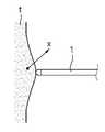
- FIG. 1ais a conventional energy transfer mechanism (1)
- Figure 1bis a diagram showing a temperature graph with distance with respect to the heat generated when using the conventional energy transfer mechanism.
- tissue (t)when treating tissue (t) by delivering RF energy, the body fluid or tissue around the electrode is heated in accordance with the delivery of RF energy. At this time, the closer to the electrode, the temperature is increased by the transmitted RF energy, and the ambient temperature is increased by the heat generated from the electrode itself. At this time, the temperature of the tissue (t) or body fluid (or liquid supplied from the outside at the time of treatment) around the electrode may be over 100 degrees. Therefore, not only the tissues to be treated but also the surrounding tissues may cause degeneration or destruction of the tissues by heat. At this time, the RF energy is instantaneously transferred a lot of energy and the heat generation of the electrode is also performed at a fast time, the destruction of unwanted tissue can occur in a very short time.
- FIG 2is a side view of a first embodiment according to the present invention.
- the treatment instrument having a switch function using the shape memory alloy according to the present inventionmay be configured to include a body portion 100, the insertion portion 200 and the treatment portion 300.
- Body portion 100constitutes the overall body, and is configured to allow the user to perform gripping and manipulation.
- Body portion 100may be configured to include a holding unit 110, the operation unit 120, the trigger 130, the connection port 140.
- the gripping unit 110may be configured to perform the treatment in a state in which the user grips the treatment instrument.
- the holding unit 110is configured to protrude a predetermined length so that the user can be held by hand, and may be configured to operate the trigger 130 to be described later when held.
- the operation unit 120may be configured to adjust the bending amount of the insertion unit 200 to be described later.
- the operation unit 120may adjust the bending amount by adjusting the lever at a predetermined angle, and the mechanical shape of the operation lever may be configured to be flexible in one direction to two directions or a plurality of directions.
- the trigger 130is configured to selectively transfer energy during treatment in the insertion unit 200 to be described later.
- the trigger 130may be provided at a position adjacent to the gripper 110 so that a user may operate while holding the gripper 110.
- Connection port 140is connected to the cable is configured to transmit and receive power and signals or video signals with the outside.
- the configuration of the manipulation unit 120is an example, and may be modified and applied in various configurations.
- Insertion portion 200is inserted into the body is configured so that the end is approaching the affected part.
- Insertion unit 200may be connected to one side of the body portion 100 may be configured in a shape extending in the longitudinal direction.
- Insertion unit 200may be formed to have a smooth outer surface as a whole so that it can be inserted into the body through a working channel formed in a sheath or catheter inserted into the body. At this time, the entire diameter of the insertion part 200 may be formed within a predetermined size to prevent interference during insertion.
- the treatment unit 300 and the switch unit 400may be provided at an end of the insertion unit 200, and a bending unit 210 may be provided at a point spaced a predetermined length from the treatment unit 300.
- the bending unit 210is configured to bend by the manipulation of the operation unit 120 described above, and is configured to perform the treatment at various angles after the insertion unit 200 is inserted into the body.
- Inside the insertion unit 200may be provided with a direction control means such as a direction control wire to bend the bending portion 210 by the manipulation of the operation unit 120.
- the direction control meansis a wire, but is not limited thereto.
- Treatment unit 300is configured to receive tissue from the outside to treat the tissue.
- the treatment unit 300may be configured to include an electrode to transmit RF energy.
- the treatment unit 300may be configured as a monopolar or bipolar type, but the bipolar type will be described below.
- the energy delivered from the treatment unit 300may be energy such as laser, ultrasound, etc.
- the RF energywill be described by way of example.
- the switch unit 400may be configured to selectively transfer energy in response to temperature changes.
- the switch unit 400may be configured to include a shape memory alloy whose shape varies according to temperature change.
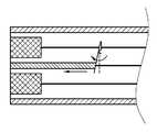
- FIG 3is a view showing the cutting of the end of the insertion unit 200
- Figure 4is a view showing a modified state of the deformation unit 410 according to the temperature rise.
- the treatment unit 300 and the switch unit 400may be provided at the end of the insertion unit 200.
- the treatment unit 300may be configured of a bipolar type electrode, and the first electrode 311 having an annular cross section and the circular second electrode 312 may be arranged concentrically at the end of the treatment unit 300. have. When RF energy is applied, energy is delivered along the path connecting the two electrodes to the outside of the treatment unit 300 to treat the tissue.
- the switch unit 400is provided inside the insertion unit 200 and may be provided on a path for transmitting energy to the electrode.
- the switch unit 400may be configured as a deformation unit 410 electrically connected to two points corresponding to two electrodes.
- the deformable portion 410may be a shape memory alloy whose shape or length changes with temperature change.
- each deformable portion 410is composed of a pair consisting of a first member 411 connected to the electrode side, the second member 412 is fixed to the inner end of the insertion portion 200 is installed, respectively
- the pair ofmay be provided in the first electrode 311 and the second electrode 312, respectively, may be configured to stop the application of energy when any one of the contact is released.
- the first member 411 and the second member 412 of the first electrode 311may be electrically connected to the first electrode 311 and at the same time, may have a large contact cross section to facilitate heat transfer. It may be configured to be in contact with the outer wall of the insertion unit 200 to receive external heat energy from the outer wall of the part 200.
- the first member 411 and the second member 412 provided in the second electrode 312is provided in the central portion of the insertion portion 200 to receive the heat transfer from the second electrode 312 so that deformation is made. Can be configured.
- the second member 412may be connected to the conductive wire 500 disposed along the insertion portion.
- the first member 411 and the second member 412is configured in a somewhat long shape in the longitudinal direction, and may be deformed in the longitudinal direction during thermal deformation and include a portion that is in surface contact or line contact with each other at a predetermined length. Can be. That is, it is configured to generate a lot of deformation in the longitudinal direction is configured to reduce the deviation in the final disconnected temperature.
- the first member 411 and the second member 412are contracted as the temperature increases, and the contact is maintained for the first length to supply energy. When the first member 411 and the second member 412 are contracted over the first length, the contact is released and mutually released. It may be configured to be spaced apart.
- the material of the shape memory alloymay be nickel-titanium alloy, and the shape of the first member 411 and the second member 412 may be determined according to a temperature to be contracted and disconnected.
- the minimum temperature in the bodymay be 37.5 degrees, it is possible to analyze the heat distribution from the outer surface of the insertion portion 200 to a predetermined distance and set the temperature of the shape memory alloy according to the limit temperature for preventing damage to normal tissue.
- the limit temperature for preventing damage to the normal tissuemay be 100 degrees Celsius near the end of the treatment unit 300 2mm.
- the temperature inside the electrodemay be 200 degrees Celsius, and in this case, the shape memory alloy may be configured to be disconnected when raised to 150 degrees Celsius.
- the above-described temperatureis an example, and various temperature distributions may be made according to the thickness of the treatment unit 300, the electrode arrangement, the size of the electrode, and the size of the applied RF energy. 1 length can be variously applied accordingly. And the shape memory alloy material can be applied in various ways.
- FIG. 5is a temperature graph with time in the application of the first embodiment. As shown, a temperature graph over time is shown at one point around the intracavity treatment part 300 and the deformation part 410.
- the temperature change tendency of one point around the body cavity treatment unit 300may be distributed in a tendency that the maximum temperature is slightly lowered away from the treatment unit 300.
- the first section (i)when RF energy is first applied, heating starts at the same temperature as the body temperature at a specific point. When RF energy is continuously applied, the temperature rises rapidly. As described above, the temperature of a specific point is increased due to energy transfer to surrounding tissue and heat transfer from the electrode itself.
- the deformable portion 410 in contact with the treatment part 300may also be rapidly heat-heated from the surrounding tissue because heat energy is rapidly transmitted from the electrode. In this case, when the temperature of the deformable portion 410 corresponding to the surrounding tissue temperature of 100 degrees is 150 degrees, the contact between the first member 411 and the second member 412 is released.
- the switch unit 400cuts off the connection so that RF energy is not applied. Therefore, the temperature of the surrounding tissue is gradually lowered, but the temperature of the inner deformable portion 410 rises and falls slightly in response to the thermal energy remaining on the electrode. Then, when the temperature of the deformable portion 410 is 150 degrees Celsius or less, the temperature of the surrounding tissue is also lowered until the section (iii) of contacting again to apply RF energy. After that, when the temperature of the contact portion 420 is 150 degrees Celsius or more, it is disconnected again, and the application of RF energy is terminated, thereby gradually decreasing the temperature. (Iv)
- the graphshows an example in which the RF energy is disconnected once, and in the case of repeatedly using the treatment instrument during surgery, the disconnection may be repeatedly made.
- the temperature of the surrounding tissuehas been described as an example, it can be equally applied to the temperature of the body fluid as well as the surrounding tissue.
- FIGS. 6 to 9Another embodiment according to the present invention will be described with reference to FIGS. 6 to 9.
- the same componentsare omitted in order to avoid redundant descriptions and to explain in detail the configuration different, and also omitted from the drawings Can be displayed.
- FIG. 6Ais a cross-sectional view of the end of the inserting portion 200 of the second embodiment, and FIGS. 6B and C are operating states of the second embodiment.
- the first electrode and the second electrodeare exposed at the end of the insertion portion, and wires connected to the first electrode 311 and the second electrode 312 are provided inside the insertion portion.
- Each wireis provided with a contact portion 420 that is configured in a contact manner and the contact is released when a supporting force is applied.
- the contact partmay be configured such that contact may be determined according to a bearing force generated by deformation of the deformable part 410.
- each deformable portion 410is elongated shape is disposed in the longitudinal direction inside the insertion portion, one side is exposed to the outside of the insertion portion, the other side is connected to a part of the contact portion 420, so that the contact is released by the contraction Can be configured.
- the deformation portion 410is shortened due to the temperature rise, on the contrary, as the temperature increases, the length increases, and accordingly includes a mechanism that can disconnect the contact portion 420 Can be configured.
- an insulatormay be provided around the deformable part 410 or between the contact parts 420 to prevent the RF energy from being transmitted through the deformable part 410.
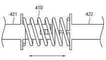
- the configuration of the switch unit 400may be composed of a contact portion 420 and the deformable portion 410.
- the deformable portion 410may be configured in the shape of a coil spring.
- the coil springis composed of a shape memory alloy, and may be configured to support one side of the contact portion 420 inside.
- the contact part 420may include a first support part 421 and a second support part 422, and may be configured to be in surface contact or line contact so as to maintain contact even when a predetermined distance moves in the longitudinal direction.
- the contact part 420forms a path for transmitting energy to the electrode and is configured to selectively transmit energy according to the contact between the first support part 421 and the second support part 422.
- the heatingis made when the treatment unit 300 is operated, the deformation unit 410 is heated by receiving thermal energy from the electrode side.
- the shape memoryis set so that the deformable portion 410 is elongated according to the temperature rise. Therefore, as the length is elongated, the supporting force for gradually pushing the second support portion 422 increases, and the supporting force gradually increases when the limit temperature is reached. As a result, the contact between the first support part 421 and the second support part 422 is released.
- the deformable portion 410is contracted to its original length, and the first support portion 421 and the second support portion 422 may be in contact again.
- a separate elastic partmay be provided at a point facing the contact point of the second support part 422 and the deformation part 410 to provide a restoring force upon return.
- FIG 8is a partial cross-sectional view of the inserting part 200 of another embodiment. As shown, the configuration of the electrode may be provided spaced apart a predetermined distance in the longitudinal direction of the insertion portion (200).
- the switch unit 400includes a deformable portion 410 in the form of a coil spring, and is provided with a contact portion 420 supported by the deformable portion 410.
- the contact portion 420is configured in the form of a plate switch supported by the coil spring, the contact is released when the deformable portion 410 is elongated according to the temperature change, the contact is made when it is contracted again.
- the contact part 420may be in surface contact, but the surface contact direction is perpendicular to the direction in which the deformation part 410 is deformed, thereby making the function of on and off more or less sensitive. As a result, even if the deformation of the deformable portion 410 is small, disconnection can be easily performed.
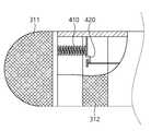
- FIG. 9is a partial cross-sectional view of the inserting portion 200 of another embodiment.
- the deformable portion 410 of the switch unit 400may be configured to include an exposed portion 412 exposed to the outside of the insertion portion 200. Therefore, the deformation part 410 may be directly deformed as the temperature of the body fluid or tissue adjacent to the treatment part 300 increases. At this time, unlike the above-described embodiment, the deformable portion 410 does not directly contact the electrode, and does not change sensitively to the temperature rise of the electrode. Therefore, it can be changed sensitively to the temperature of external body fluid or tissue.
- the exposed portion 412may be configured to a rather large area so that the heat transfer can be made smoothly, it may be arranged to form a smooth outer surface without a protruding portion in the outer shape of the insertion portion (200).
- the deformable portion 410may be heat-transmitted from the temperature or tissue of the liquid outside the insertion unit 200, that is, the body cavity, and may be configured to receive heat from the electrode. In this case, since heat loss from the electrodes and heat loss may occur in the exposed portion 412, cooling may be performed. Accordingly, the amount of change in accordance with the temperature of the shape memory alloy may be set in consideration of this.
- the treatment tool having a switch function using the shape memory alloy described above with the drawingsautomatically cuts off the applied energy when the temperature becomes high so as to prevent excessive temperature rise in the body. It does not require a sensor, and does not require a separate control unit, it is possible to exhibit a blocking function with a simple configuration. Therefore, it is possible to make thin, improve the accuracy of the surgery, it is possible to minimize the destruction of unnecessary tissue has the effect of minimizing the sequelae.
Landscapes
- Health & Medical Sciences (AREA)
- Surgery (AREA)
- Life Sciences & Earth Sciences (AREA)
- Engineering & Computer Science (AREA)
- Biomedical Technology (AREA)
- Otolaryngology (AREA)
- Nuclear Medicine, Radiotherapy & Molecular Imaging (AREA)
- Heart & Thoracic Surgery (AREA)
- Medical Informatics (AREA)
- Molecular Biology (AREA)
- Animal Behavior & Ethology (AREA)
- General Health & Medical Sciences (AREA)
- Public Health (AREA)
- Veterinary Medicine (AREA)
- Plasma & Fusion (AREA)
- Physics & Mathematics (AREA)
- Surgical Instruments (AREA)
Abstract
Description
Translated fromKorean본 발명은 형상기억합금을 이용한 스위치 기능을 갖는 처치구에 관한 것이며, 보다 상세하게는 체내로 삽입되어 처치시 특정온도 이상으로 가열되는 것을 방지하는 스위치 기능을 갖는 형상기억합금을 이용한 스위치 기능을 갖는 처치구에 관한 것이다.The present invention relates to a treatment instrument having a switch function using a shape memory alloy, and more particularly, has a switch function using a shape memory alloy having a switch function that is inserted into the body to prevent heating above a specific temperature during treatment. It is about a treatment instrument.
체내의 조직을 처리하기 위하여, 최근에는 복강경 수술이 많이 수행되고 있으며, 이러한 복강경 수술을 위하여는 인체에 형성된 좁은 구멍을 통하여 환부에 근접하여 환부를 절개, 지혈 또는 봉합할 수 있는 수술용 도구가 이용된다.In order to process the tissues in the body, laparoscopic surgery has recently been performed a lot, and for such laparoscopic surgery, a surgical tool capable of cutting, hemostasis, or suturing the affected area near the affected area through a narrow hole formed in the human body is used. do.
이때 환부의 조직을 봉합하거나 소작 등을 수행할 때 인체에 고주파 에너지를 인가하는 전기수술용 도구가 많이 이용되고 있다. 이러한 전기수술용 기구는 대한민국 공개특허 10-2016-0007087호에 나타나 있다.At this time, when suturing the tissue of the affected area or performing cauterization, electrosurgical tools for applying high-frequency energy to the human body have been widely used. Such an electrosurgical instrument is shown in Republic of Korea Patent Publication No. 10-2016-0007087.
그러나 이와같은 수술용기구는 에너지를 체내에 전달할 때 열이 발생하며, 과도하게 가열되는 경우 주변조직에 의도치 않은 손상이 발생되는 문제점이 있었다.However, such surgical instruments generate heat when energy is delivered to the body, and there is a problem that unintentional damage occurs to surrounding tissues when excessively heated.
본 발명은 종래의 에너지를 전달하는 수술용 기구로 처치시 과도하게 가열되어 발생되는 조직의 손상을 방지하기 위한 스위치 기능을 갖는 처치구를 제공한 그것에 그 목적이 있다.An object of the present invention is to provide a treatment instrument having a switch function for preventing damage to tissue caused by excessive heating during treatment with a surgical instrument that delivers conventional energy.
상기 과제의 해결 수단으로서, 일측에 파지부가 형성되는 바디부, 바디부의 일측에 구비되며, 체강내로 삽입가능하도록 구성되는 삽입부, 삽입부의 끝단에 구비되며, 에너지를 전달하여 조직을 처치하는 처치부 및 소정온도 이상이 되는 경우 에너지를 차단할 수 있도록 구성된 형상기억합금을 포함하여 구성되는 스위치부를 포함하는 처치도구가 제공될 수 있다.As a means for solving the above problems, a body portion having a gripping portion formed on one side, provided on one side of the body portion, an insertion portion configured to be inserted into the body cavity, the treatment portion provided at the end of the insertion portion, and delivers energy to treat the tissue And it may be provided with a treatment tool comprising a switch unit comprising a shape memory alloy configured to cut off the energy when the temperature is above a predetermined temperature.
여기서, 형상기억합금은 처치부와 전기적으로 연결되며, 소정온도 이상이 되는 경우 형상기억합금의 형상이 변화되어 단선되도록 구성될 수 있다.Here, the shape memory alloy may be electrically connected to the treatment part, and may be configured to be disconnected by changing the shape of the shape memory alloy when the temperature is higher than a predetermined temperature.
한편, 스위치부는 처치부의 작동시 조직주변의 액체의 온도변화에 따라 작동할 수 있도록 일부가 액체에 노출되도록 구성될 수 있다.On the other hand, the switch unit may be configured to expose a portion of the liquid to operate in accordance with the temperature change of the liquid around the tissue during operation of the treatment unit.
또한, 스위치부는 처치부의 온도변화에 따라 작동할 수 있도록 처치부와 접촉되어 구성될 수 있다.In addition, the switch unit may be configured in contact with the treatment unit to operate according to the temperature change of the treatment unit.
한편, 스위치부는 지지력에 따라 접촉여부가 결정되는 접촉부를 포함하며, 형상기억합금의 온도에 따라 접촉부를 지지하는 지지력이 달라질 수 있도록 구성될 수 있다.On the other hand, the switch unit may include a contact portion in which contact is determined according to the bearing force, and may be configured such that the bearing force supporting the contact portion may vary according to the temperature of the shape memory alloy.
그리고, 처치부의 직경은 카테터에 삽입될 수 있도록 삽입부의 직경 이하로 구성될 수 있다.And, the diameter of the treatment portion may be configured to be less than the diameter of the insertion portion to be inserted into the catheter.
또한 스위치부는, 삽입부 내에서 서로 면접촉하는 제1 부재 및 제2 부재로 구성되며, 소정온도로 가열된 경우 제1 부재 및 제2 부재가 이격되어 단선되도록 구성될 수 있다.In addition, the switch unit may be configured of a first member and a second member which are in surface contact with each other in the insertion unit, and may be configured such that the first member and the second member are separated and disconnected when heated to a predetermined temperature.
한편, 처치부는 RF에너지를 전달하여 조직을 처치할 수 있도록 전극을 포함하여 구성될 수 있다.On the other hand, the treatment unit may be configured to include an electrode to deliver the RF energy to treat the tissue.
여기서 스위치부는, 코일 스프링의 형상으로 구성된 형상기억합금을 포함하며,접촉부는 소정온도에 가열되는 경우 코일에 의해 지지되어 접촉이 해제되도록 구성될 수 있다.Here, the switch unit may include a shape memory alloy configured in the shape of a coil spring, and the contact unit may be configured to be supported by the coil and released from contact when heated to a predetermined temperature.
또한 삽입부는 처치부의 방향을 변화시킬 수 있는 벤딩부를 더 포함하며, 파지부는 벤딩부를 조향할 수 있도록 구성되는 조작부를 더 포함하여 구성될 수 있다.In addition, the inserting portion may further include a bending portion capable of changing the direction of the treatment portion, and the gripping portion may be configured to further include an operation portion configured to steer the bending portion.
본 발명에 따른 형상기억합금을 이용한 스위치 기능을 갖는 처치구는 특정온도 이상이 되면 에너지 공급이 차단되어 과열되는 것을 방지할 수 있어 의도치 않은 조직의 손상을 방지하여 후유증 감소 및 수술 정확도를 향상시킬 수 있는 효과가 있다.The treatment tool having a switch function using the shape memory alloy according to the present invention can prevent overheating of the energy supply when the temperature is above a certain temperature, thereby preventing unintended damage to the tissues, thereby reducing sequelae and improving surgical accuracy. It has an effect.
도 1a는 종래의 에너지 전달기구, 도 1b는 종래 에너지 전달기구 사용시 발열에 대하여 거리에 따른 온도 그래프를 도시한 도면이다.Figure 1a is a conventional energy transfer mechanism, Figure 1b is a view showing a temperature graph with a distance with respect to the heat generated when using the conventional energy transfer mechanism.
도 2는 본 발명에 따른 제1 실시예의 측면도이다.2 is a side view of a first embodiment according to the present invention.
도 3은 삽입부의 끝단을 절개하여 도시한 도면이다.3 is a view showing the end of the insertion section cut.
도 4는 변형부의 변형된 모습을 도시한 도면이다.4 is a view showing a modified state of the deformable portion.
도 5는 제1 실시예의 적용시 시간에 따른 온도 그래프이다.5 is a temperature graph with time in the application of the first embodiment.
도 6a는 제2 실시예의 삽입부의 끝단의 단면도이며, 도 6b,c는 작동상태도이다.Fig. 6A is a cross sectional view of the end of the inserting portion of the second embodiment, and Figs. 6B and C are operating conditions.
도 7은 스위치부의 다른 변형예의 단면도이다.7 is a cross-sectional view of another modification of the switch unit.
도 8은 또 다른 실시예의 삽입부의 부분단면도이다.8 is a partial cross-sectional view of an insert of another embodiment.
도 9는 또 다른 실시예의 삽입부의 부분단면도이다.9 is a partial cross-sectional view of the insert of another embodiment.
이하, 본 발명의 실시 예에 따른 형상기억합금을 이용한 스위치 기능을 갖는 처치구에 대하여, 첨부된 도면을 참조하여 상세히 설명한다. 그리고 이하의 실시예의 설명에서 각각의 구성요소의 명칭은 당업계에서 다른 명칭으로 호칭될 수 있다. 그러나 이들의 기능적 유사성 및 동일성이 있다면 변형된 실시예를 채용하더라도 균등한 구성으로 볼 수 있다. 또한 각각의 구성요소에 부가된 부호는 설명의 편의를 위하여 기재된다. 그러나 이들 부호가 기재된 도면상의 도시 내용이 각각의 구성요소를 도면내의 범위로 한정하지 않는다. 마찬가지로 도면상의 구성을 일부 변형한 실시예가 채용되더라도 기능적 유사성 및 동일성이 있다면 균등한 구성으로 볼 수 있다. 또한 당해 기술분야의 일반적인 기술자 수준에 비추어 보아, 당연히 포함되어야 할 구성요소로 인정되는 경우, 이에 대하여는 설명을 생략한다.Hereinafter, a treatment instrument having a switch function using a shape memory alloy according to an embodiment of the present invention will be described in detail with reference to the accompanying drawings. And the names of each component in the description of the following embodiments may be called other names in the art. However, if their functional similarity and identity, even if the modified embodiment can be seen as an equivalent configuration. In addition, the symbols added to each component is described for convenience of description. However, the contents shown in the drawings in which these symbols are described do not limit each component to the ranges in the drawings. Similarly, even if an embodiment in which the configuration on the drawings is partially modified is employed, it can be regarded as an equivalent configuration if there is functional similarity and identity. In addition, in view of the general level of those skilled in the art, if it is recognized as a component to be included naturally, the description thereof will be omitted.
도 1a은 종래의 에너지 전달기구(1), 도 1b는 종래 에너지 전달기구 사용시 발열에 대하여 거리에 따른 온도 그래프를 도시한 도면이다. 도시된 바와 같이, RF에너지를 전달하여 조직(t)을 처치할 때 RF에너지의 전달에 따라 전극 주변의 체액 또는 조직은 가열된다. 이때 전극에 가까울수록 전달되는 RF에너지에 의해 온도가 상승하게 되며, 또한 전극 자체에서 발생되는 열에 의하여 주변의 온도가 상승하게 된다. 이때 전극 주변의 조직(t) 또는 체액(또는 처치시 외부에서 공급되는 액체)의 온도는 100도를 넘을 수 있다. 따라서 처치 대상이 되는 조직 뿐 아니라 주변의 조직까지도 열에 의한 조직의 변성 또는 파괴가 일어날 수 있다. 이때 RF에너지는 순간적으로 많은 에너지가 전달되고 전극의 발열 또한 빠른 시간에 이루어지므로 원하지 않는 조직의 파괴는 매우 짧은 시간내에 발생될 수 있다.Figure 1a is a conventional energy transfer mechanism (1), Figure 1b is a diagram showing a temperature graph with distance with respect to the heat generated when using the conventional energy transfer mechanism. As shown, when treating tissue (t) by delivering RF energy, the body fluid or tissue around the electrode is heated in accordance with the delivery of RF energy. At this time, the closer to the electrode, the temperature is increased by the transmitted RF energy, and the ambient temperature is increased by the heat generated from the electrode itself. At this time, the temperature of the tissue (t) or body fluid (or liquid supplied from the outside at the time of treatment) around the electrode may be over 100 degrees. Therefore, not only the tissues to be treated but also the surrounding tissues may cause degeneration or destruction of the tissues by heat. At this time, the RF energy is instantaneously transferred a lot of energy and the heat generation of the electrode is also performed at a fast time, the destruction of unwanted tissue can occur in a very short time.
도 2는 본 발명에 따른 제1 실시예의 측면도이다.2 is a side view of a first embodiment according to the present invention.
도시된 바와 같이, 본 발명에 따른 형상기억합금을 이용한 스위치 기능을 갖는 처치구는 바디부(100), 삽입부(200) 및 처치부(300)를 포함하여 구성될 수 있다.As shown, the treatment instrument having a switch function using the shape memory alloy according to the present invention may be configured to include a
바디부(100)는 전체적인 몸체를 구성하며, 사용자가 파지 및 조작을 수행할 수 있도록 구성된다. 바디부(100)는 파지부(110), 조작부(120), 트리거(130), 연결포트(140)를 포함하여 구성될 수 있다. 파지부(110)는 사용자가 처치구를 파지한 상태로 처치를 수행할 수 있도록 구성될 수 있다. 파지부(110)는 사용자가 손으로 파지가능하도록 소정길이 돌출되어 구성되며, 파지하였을 때 후술할 트리거(130)를 조작가능한 위치게 구성될 수 있다. 조작부(120)는 후술할 삽입부(200)의 벤딩량을 조절할 수 있도록 구성될 수 있다. 조작부(120)는 소정각도로 레버를 조절하여 벤딩량을 조절할 수 있으며, 1방향 내지 2방향 또는 복수의 방향으로 벤딩이 다능하도록 조작레버의 기구적인 형상이 구성될 수 있다. 트리거(130)는 후술할 삽입부(200)에서 처치시 에너지를 전달이 선택적으로 이루어질 수 있도록 구성된다. 트리거(130)는 사용자가 파지부(110)를 파지한 채로 조작할 수 있도록 파지부(110)와 인접한 위치에 구비될 수 있다. 연결포트(140)는 케이블이 연결되어 전원 및 신호 또는 영상신호를 외부와 송수신할 수 있도록 구성된다. 한편 이와같은 조작부(120)의 구성은 일 예이며, 다양한 구성으로 변형되어 적용될 수 있다.
삽입부(200)는 체내로 삽입되어 끝단이 환부에 접근할 수 있도록 구성된다. 삽입부(200)는 바디부(100)의 일측에 연결되어 길이방향으로 연장된 형상으로 구성될 수 있다. 삽입부(200)는 체내에 삽입된 시스(sheath) 또는 카테터(catheter) 내에 형성된 워킹채널을 통하여 체내에 삽입될 수 있도록 전체적으로 매끄러운 외면을 갖도록 형성될 수 있다. 이때, 삽입시 간섭을 방지할 수 있도록 삽입부(200)의 전체적인 직경은 소정크기 이내로 형성될 수 있다.
삽입부(200)의 끝단에는 처치부(300) 및 스위치부(400)가 구비될 수 있으며, 그로부터 소정길이 이격된 지점에는 벤딩부(210)가 구비될 수 있다. 벤딩부(210)는 전술한 조작부(120)의 조작에 의하여 벤딩이 이루어질 수 있도록 구성되며, 삽입부(200)가 체내에 삽입된 이후 다양한 각도로 처치를 수행할 수 있도록 구성된다. 삽입부(200)의 내측에는 조작부(120)의 조작에 의해 벤딩부(210)의 벤딩이 이루어질 수 있도록 방향조절 와이어 등의 방향조절수단이 구비될 수 있다. 한편 방향조절수단은 와이어를 예로 들었으나 이에 한정하는 것은 아니다.The
처치부(300)는 외부로부터 에너지를 전달받아 조직을 처치할 수 있도록 구성된다. 처치부(300)는 RF에너지를 전달할 수 있도록 전극을 포함하여 구성될 수 있다. 처치부(300)는 monopolar 또는 bipolar 타입으로 구성될 수 있으나, 이하에서는 bipolar type을 예를 들어 기술하기로 한다. 한편, 처치부(300)에서 전달되는 에너지는 레이저, 초음파 등의 에너지가 될 수 있으나 이하에서는 RF에너지를 예를 들어 설명하기로 한다.
스위치부(400)는 온도변화에 따라 에너지의 전달이 선택적으로 이루어질 수 있도록 구성될 수 있다. 스위치부(400)는 온도변화에 따라 형상이 달라지는 형상기억합금을 포함하여 구성될 수 있다.The
한편 이러한 처치부(300) 및 스위치부(400)에 대하여는 이하에서 상세히 설명하기로 한다.On the other hand, the
도 3은 삽입부(200)의 끝단을 절개하여 도시한 도면이며, 도 4는 온도 상승에 따른 변형부(410)의 변형된 모습을 도시한 도면이다. 도시된 바와 같이 삽입부(200)의 끝단에는 처치부(300) 및 스위치부(400)가 구비될 수 있다.3 is a view showing the cutting of the end of the
처치부(300)는 bipolar 타입의 전극으로 구성될 수 있으며, 처치부(300)의 끝단에서 단면이 고리형인 제1 전극(311)과 원형인 제2 전극(312)이 동심을 이루며 배치될 수 있다. RF에너지를 인가하면 처치부(300)의 외부에 두 전극을 잇는 경로를 따라 에너지가 전달되어 조직을 처치하게 된다.The
*스위치부(400)는 삽입부(200)의 내측에 구비되며, 전극에 에너지를 전달하는 경로상에 구비될 수 있다. 스위치부(400)는 두 개의 전극에 대응하여 두 지점에 전기적으로 연결되는 변형부(410)로 구성될 수 있다. 변형부(410)는 온도변화에 따라 그 형상 또는 길이가 변화되는 형상기억합금이 될 수 있다. 이때 각각의 변형부(410)는 전극측과 연결되는 제1 부재(411), 삽입부(200)의 내측에 끝단이 고정되어 설치되는 제2 부재(412)로 구성되는 한 쌍으로 구성되며 각각의 쌍은 제1 전극(311) 및 제2 전극(312)에 각각 구비되어 둘 중 어느 하나의 접촉이 해제되면 에너지 인가가 중단되도록 구성될 수 있다.The
제1 전극(311)에 구비된 제1 부재(411) 및 제2 부재(412)는 제1 전극(311)과 전기적으로 연결됨과 동시에 열전달이 용이하도록 접촉단면이 크게 구성될 수 있으며, 또한 삽입부(200)의 외벽으로부터 외부의 열에너지를 전달받을 수 있도록 삽입부(200)의 외벽과 접촉되어 구성될 수 있다. 한편, 제2 전극(312)에 구비된 제1 부재(411) 및 제2 부재(412)는 삽입부(200)의 중심부분에 구비되어 제2 전극(312)으로부터 열전달을 받아 변형이 이루어지도록 구성될 수 있다. 한편 제2 부재(412)는 삽입부를 따라 배치된 도선(500)과 연결될 수 있다.The
제1 부재(411)와 제2 부재(412)는 길이방향으로 다소 긴 형상으로 구성되며, 열변형시 길이방향으로 변형될 수 있으며 소정길이로 서로 면접촉 또는 선접촉하는 부분을 포함하여 구성될 수 있다. 즉 열에 의한 변형이 길이방향으로 많이 발생되도록 구성되어 최종적으로 단선되는 온도에 편차를 줄일 수 있도록 구성된다. 구체적으로 제1 부재(411)와 제2 부재(412)는 온도가 상승함에 따라 수축되어 제1 길이 동안은 접촉이 유지되어 에너지가 공급되고, 제1 길이 이상으로 수축된 경우 접촉이 해제되고 서로 이격되어 단선되도록 구성될 수 있다.The
형상기억합금의 재질은 니켈-티타늄 합급이 될 수 있으며, 수축되어 단선되어야 하는 온도에 따라 제1 부재(411) 및 제2 부재(412)의 형상이 결정될 수 있다. 체내의 최저온도는 37.5도가 될 수 있으며, 삽입부(200)의 외면에서부터 소정거리까지의 열분포를 분석하고 정상조직의 손상을 방지하기 위한 한계온도에 따른 형상기억합금의 온도를 설정할 수 있다. 이때 정상조직의 손상을 방지하기 위한 한계온도는 처치부(300) 끝단 2mm 부근에서 섭씨 100도가 될 수 있다. 이 때 전극 내부의 온도는 섭씨 200도가 될 수 있으며, 이 경우 형상기억합금은 섭씨 150도로 상승되는 경우 단선되도록 구성될 수 있다. 다만 전술한 온도는 일 예이며, 처치부(300)의 두께, 전극의 배치, 전극의 크기 및 인가되는 RF에너지의 크기에 따라 다양한 온도분포가 이루어질 수 있으며, 이때 형상기억합금의 면접촉되는 제1 길이는 이에 따라 다양하게 적용될 수 있다. 그리고 형상기억합금의 재질 또한 다양하게 적용될 수 있다.The material of the shape memory alloy may be nickel-titanium alloy, and the shape of the
도 5는 제1 실시예의 적용시 시간에 따른 온도 그래프이다. 도시된 바와 같이 체강내 처치부(300) 주변의 일 지점 및 변형부(410)에서 시간에 따른 온도그래프가 나타나 있다. 체강내 처치부(300) 주변의 일 지점의 온도변화 경향은 처치부(300)로부터 멀어질 수 록 최대온도가 다소 낮아지는 경향으로 분포될 수 있다. 제1 구간(i)에서는 RF에너지를 처음으로 인가하면 특정지점에서는 체온과 동일한 온도에서부터 가열이 되기 시작한다. 지속적으로 RF에너지를 인가하면 급격하게 온도가 상승되는데, 이때 전술한 바와 같이, 주변 조직에 에너지전달 및 전극 자체로부터의 열전달로 인하여 특정지점의 온도가 상승된다. 또한 처치부(300)와 접촉되어 있는 변형부(410) 또한 전극에서의 열에너지가 빠르게 전달되어 주변조직보다 급격하게 온도가 상승될 수 있다. 이때 주변 조직온도 100도에 대응되는 변형부(410)의 온도는 150도가 될 때 제1 부재(411)와 제2 부재(412)의 접촉이 해제된다.5 is a temperature graph with time in the application of the first embodiment. As shown, a temperature graph over time is shown at one point around the
제2 구간(ii)에서는 스위치부(400)에서 연결을 차단하므로 RF에너지가 인가되지 않는 구간이다. 따라서 주변 조직의 온도는 점차 낮아지게 되나, 내부의 변형부(410)의 온도는 전극에 잔존하는 열에너지를 받아 다소 상승하였다가 하강한다. 이후 변형부(410)의 온도가 섭씨 150도 이하가 되는 경우 다시 접촉되어 RF에너지를 인가하는 구간(iii) 전까지 주변 조직의 온도도 하강하게 된다. 이후 접촉부(420)의 온도가 섭씨 150도 이상이 되는 경우 다시 단선되며 RF에너지 인가가 종료되어 점차 온도가 낮아지게 된다.(iv)In the second section (ii), the
다만, 그래프에서는 RF에너지가 한번 단선되는 예가 나타나 있으며, 수술시 처치구를 반복적으로 사용하는 경우에는 반복적으로 단선이 이루어질 수 있다. 한편, 이상에서는 주변 조직의 온도를 예를 들어 설명하였으나, 주변 조직 뿐 아니라 체액의 온도에도 동일하게 적용될 수 있다.However, the graph shows an example in which the RF energy is disconnected once, and in the case of repeatedly using the treatment instrument during surgery, the disconnection may be repeatedly made. On the other hand, while the temperature of the surrounding tissue has been described as an example, it can be equally applied to the temperature of the body fluid as well as the surrounding tissue.
이하에서는 도 6 내지 도 9를 참조하여 본 발명에 따른 다른 실시예에 대하여 설명하도록 한다. 이하의 실시예에서도 전술한 실시예와 동일한 구성요소를 포함하여 구성될 수 있으며, 동일한 구성요소에 대하여는 중복기재를 피하기 위하여 설명을 생략하고 차이가 있는 구성에 대하여 상세히 설명하도록 하며, 도면상에서도 생략되어 표시될 수 있다.Hereinafter, another embodiment according to the present invention will be described with reference to FIGS. 6 to 9. In the following embodiments may be configured to include the same components as the above-described embodiment, the same components are omitted in order to avoid redundant descriptions and to explain in detail the configuration different, and also omitted from the drawings Can be displayed.
도 6a는 제2 실시예의 삽입부(200)의 끝단의 단면도이며, 도 6b,c는 제2 실시예의 작동상태도이다. 도 6a에 도시된 바와 같이, 삽입부의 끝단에는 제1 전극 및 제2 전극이 노출되어 있으며, 제1 전극(311) 및 제2 전극(312) 각각에 연결되는 전선이 삽입부의 내측에 구비되어 있다. 각 전선에는 접촉식으로 구성되어 지지력이 인가되는 경우 접촉이 해제되는 접촉부(420)가 구비되어 있다. 도 6b,c에 나타난 바와 같이 접촉부는 변형부(410)가 변형되어 발생되는 지지력에 따라 접촉여부가 결정될 수 있도록 구성될 수 있다. 이때 각각의 변형부(410)는 길다란 형상으로 삽입부의 내측에 길이방향으로 배치되며, 일측이 삽입부의 외측으로 노출되며, 타측은 접촉부(420)의 일부와 연결되며, 수축에 의해 접촉이 해제되도록 구성될 수 있다. 다만, 본 실시예에서는 온도상승에 의해 길이가 짧아지는 변형부(410)를 예를 들었으나, 이와 반대로 온도가 상승하면 길이가 증가하며, 이에 따라 접촉부(420)가 단선될 수 있는 메커니즘을 포함하여 구성될 수 있다.6A is a cross-sectional view of the end of the inserting
한편 도시되지는 않았으나, RF에너지가 변형부(410)를 통하여 전달되는 것을 방지할 수 있도록 변형부(410) 주변 또는 접촉부(420) 사이에는 절연체가 구비될 수 있다.Although not shown, an insulator may be provided around the
도 7은 스위치부의 다른 변형예의 단면도이다. 도시된 바와 같이, 스위치부(400)의 구성이 접촉부(420)와 변형부(410)로 구성될 수 있다. 이때 변형부(410)는 코일 스프링의 형상으로 구성될 수 있다. 코일 스프링은 형상기억합금으로 구성되며, 내측에 접촉부(420)의 일측을 지지하도록 구성될 수 있다. 접촉부(420)는 제1 지지부(421)와 제2 지지부(422)로 구성되며, 서로 길이방향으로 소정거리 이동시에도 접촉이 유지될 수 있도록 면접촉 또는 선접촉되는 구성으로 구성될 수 있다. 접촉부(420)는 전극에 에너지를 전달하는 경로를 구성하며 제1 지지부(421)와 제2 지지부(422)의 접촉에 따라 에너지가 선택적으로 전달될 수 있도록 구성된다.7 is a cross-sectional view of another modification of the switch unit. As shown, the configuration of the
본 실시예의 스위치부(400)의 동작을 살펴보면, 처치부(300)를 작동하는 경우 가열이 이루어지며, 전극측으로부터 열에너지를 전달받아 변형부(410)가 가열된다. 이때 변형부(410)는 온도상승에 따라 신장이 이루어지도록 형상기억이 설정되며 따라서 길이가 신장되면서 제2 지지부(422)를 점차적으로 밀어내는 지지력이 커지게 되고 한계온도에 도달하면 점차적으로 지지력이 커지게 되어 결국 제1 지지부(421)와 제2 지지부(422)의 접촉이 해제된다. 다시 온도가 낮아지는 경우 변형부(410)는 원래길이로 수축하게 되고 제1 지지부(421)와 제2 지지부(422)는 재접촉이 이루어질 수 있다.Looking at the operation of the
한편, 도시되지는 않았으나, 제2 지지부(422)와 변형부(410)가 접촉되는 지점과 대향하는 지점에서 별도의 탄성부가 구비되어 복귀시 복원력을 제공하도록 구성될 수 있다.Although not shown, a separate elastic part may be provided at a point facing the contact point of the
도 8은 또 다른 실시예의 삽입부(200)의 부분단면도이다. 도시된 바와 같이, 전극의 구성이 삽입부(200)의 길이방향으로 소정거리 이격되어 구비될 수 있다.8 is a partial cross-sectional view of the inserting
스위치부(400)는 변형부(410)가 코일 스프링의 형태로 구성되며, 이에 의해 지지되는 접촉부(420)가 구비되어 있다. 접촉부(420)는 코일스프링에 지지되는 플레이트 스위치의 형태로 구성되며, 온도변화에 따라 변형부(410)가 신장되면 접촉이 해제되고, 다시 수축하게 되면 접촉이 이루어진다. 이때 접촉부(420)는 면접촉이 이루어지나 면접촉 방향이 변형부(410)가 변형되는 방향과 수직으로 이루어져 온오프의 기능이 다소 민감하게 이루어 질 수 있게 된다. 결국 변형부(410)의 변형이 작더라도 쉽게 단선이 이루어 질 수 있게 된다.The
도 9는 또 다른 실시예의 삽입부(200)의 부분단면도이다.9 is a partial cross-sectional view of the inserting
도시된 바와 같이, 스위치부(400)의 변형부(410)는 삽입부(200)의 외측에 노출되는 노출부(412)를 포함하여 구성될 수 있다. 따라서 처치부(300)에 인접한 체액 또는 조직의 온도가 상승함에 따라 직접적으로 변형부(410)가 변형되도록 구성될 수 있다. 이때 전술한 실시예와 달리 변형부(410)가 전극과 직접적으로 접촉되지 않으며, 전극의 온도상승에 민감하게 변화되지 않는다. 따라서 외부 체액 또는 조직의 온도에 민감하게 변화될 수 있게 된다. 이때 노출부(412)는 열전달이 원활하게 이루어질 수 있도록 다소 넓은 면적으로 구성될 수 있으며, 삽입부(200)의 외형에 돌출된 부분 없이 매끄러운 외면을 형성할 수 있도록 배치될 수 있다.As shown, the
한편 이상에서 설명하지는 않았으나, 변형부(410)는 삽입부(200) 외부, 즉 체강내의 액체의 온도 또는 조직으로부터 열전달받으며, 전극으로부터도 열전달 받을 수 있도록 구성될 수 있다. 이 경우 전극으로부터의 열전달 및 노출부(412)로 열손실이 일어나 냉각이 이루어질 수 있으므로, 이를 고려하여 형상기억합금의 온도에 따른 변화량을 설정할 수 있게 된다.Although not described above, the
이상에서 도면과 함께 설명한 형상기억합금을 이용한 스위치 기능을 갖는 처치구는 체내에 과도한 온도상승을 방지할 수 있도록 인가되는 에너지를 고온이 되면 자동으로 차단하게 되며, 내부의 기구적인 스위치를 이용하게 되므로 별도의 센서가 필요하지 않고, 별도의 제어부를 필요로 하지 않으므로 간단한 구성으로 차단 기능을 발휘할 수 있게 된다. 따라서 얇게 제작이 가능하며, 수술의 정확도가 향상되고, 불필요한 조직의 파괴를 최소화 할 수 있어 후유증을 최소화 할 수 있는 효과가 있다.The treatment tool having a switch function using the shape memory alloy described above with the drawings automatically cuts off the applied energy when the temperature becomes high so as to prevent excessive temperature rise in the body. It does not require a sensor, and does not require a separate control unit, it is possible to exhibit a blocking function with a simple configuration. Therefore, it is possible to make thin, improve the accuracy of the surgery, it is possible to minimize the destruction of unnecessary tissue has the effect of minimizing the sequelae.
Claims (10)
Translated fromKoreanApplications Claiming Priority (2)
| Application Number | Priority Date | Filing Date | Title |
|---|---|---|---|
| KR1020170033055AKR20180105848A (en) | 2017-03-16 | 2017-03-16 | A treatment tool having a switch function using a shape memory alloy |
| KR10-2017-0033055 | 2017-03-16 |
Publications (1)
| Publication Number | Publication Date |
|---|---|
| WO2018169138A1true WO2018169138A1 (en) | 2018-09-20 |
Family
ID=63524003
Family Applications (1)
| Application Number | Title | Priority Date | Filing Date |
|---|---|---|---|
| PCT/KR2017/007992CeasedWO2018169138A1 (en) | 2017-03-16 | 2017-07-25 | Treatment apparatus having switch function and using shape memory alloy |
Country Status (2)
| Country | Link |
|---|---|
| KR (1) | KR20180105848A (en) |
| WO (1) | WO2018169138A1 (en) |
Citations (5)
| Publication number | Priority date | Publication date | Assignee | Title |
|---|---|---|---|---|
| US5823955A (en)* | 1995-11-20 | 1998-10-20 | Medtronic Cardiorhythm | Atrioventricular valve tissue ablation catheter and method |
| KR20010020843A (en)* | 1999-08-06 | 2001-03-15 | 듀벨 버나드 에스. | Temperature responsive switch with shape memory actuator |
| US20080281310A1 (en)* | 2007-05-11 | 2008-11-13 | Tyco Healthcare Group Lp | Temperature monitoring return electrode |
| US20120203224A1 (en)* | 2011-02-08 | 2012-08-09 | Gyrus Medical, Inc. | Single-use electronic apparatus having a thermal switch |
| KR20130055895A (en)* | 2011-11-21 | 2013-05-29 | 동아대학교 산학협력단 | Power switch using shape memory alloy |
- 2017
- 2017-03-16KRKR1020170033055Apatent/KR20180105848A/ennot_activeCeased
- 2017-07-25WOPCT/KR2017/007992patent/WO2018169138A1/ennot_activeCeased
Patent Citations (5)
| Publication number | Priority date | Publication date | Assignee | Title |
|---|---|---|---|---|
| US5823955A (en)* | 1995-11-20 | 1998-10-20 | Medtronic Cardiorhythm | Atrioventricular valve tissue ablation catheter and method |
| KR20010020843A (en)* | 1999-08-06 | 2001-03-15 | 듀벨 버나드 에스. | Temperature responsive switch with shape memory actuator |
| US20080281310A1 (en)* | 2007-05-11 | 2008-11-13 | Tyco Healthcare Group Lp | Temperature monitoring return electrode |
| US20120203224A1 (en)* | 2011-02-08 | 2012-08-09 | Gyrus Medical, Inc. | Single-use electronic apparatus having a thermal switch |
| KR20130055895A (en)* | 2011-11-21 | 2013-05-29 | 동아대학교 산학협력단 | Power switch using shape memory alloy |
Also Published As
| Publication number | Publication date |
|---|---|
| KR20180105848A (en) | 2018-10-01 |
Similar Documents
| Publication | Publication Date | Title |
|---|---|---|
| US6994709B2 (en) | Treatment device for tissue from living tissues | |
| EP2934358B1 (en) | Magnetic activation of monopolar and bipolar devices | |
| EP1527744B1 (en) | Medical instrument for endoscope | |
| CN101455584A (en) | A catheter assembly | |
| US9949792B2 (en) | Pressure-sensitive flexible polymer bipolar electrode | |
| CA2946390C (en) | Multi-functional electrosurgical plasma accessory | |
| US11266462B2 (en) | Medical instrument for tissue ablation by means of an HF electrode with the function of a controlled distal angular orientation | |
| SE445882B (en) | ELECTRO-SURGICAL DEVICE FOR TREATMENT OF TISSUE | |
| US8454600B2 (en) | Two piece tube for suction coagulator | |
| US20210030462A1 (en) | Catheter device | |
| JP2023523858A (en) | Electrode assembly for endoscopic surgery | |
| CN110650705B (en) | Presence detection of electrosurgical tools in robotic systems | |
| JP5599198B2 (en) | 2-piece tube for suction coagulator | |
| EP2263585B1 (en) | Thermal barrier for suction coagulator | |
| US8460291B2 (en) | Two piece tube for suction coagulator | |
| WO2018169138A1 (en) | Treatment apparatus having switch function and using shape memory alloy | |
| US8286339B2 (en) | Two piece tube for suction coagulator | |
| EP1847231B1 (en) | Soft bipolar forceps | |
| KR102114381B1 (en) | A treatment tool having a switch function using a shape memory alloy | |
| JP2008295905A (en) | Monopolar type high frequency knife for endoscope | |
| EP3128938B1 (en) | Bipolar device for the surgical resection of tissues | |
| US20200326357A1 (en) | Energy treatment instrument | |
| WO2020262897A1 (en) | Surgical tool for incising and suturing target tissue |
Legal Events
| Date | Code | Title | Description |
|---|---|---|---|
| 121 | Ep: the epo has been informed by wipo that ep was designated in this application | Ref document number:17900815 Country of ref document:EP Kind code of ref document:A1 | |
| NENP | Non-entry into the national phase | Ref country code:DE | |
| 32PN | Ep: public notification in the ep bulletin as address of the adressee cannot be established | Free format text:NOTING OF LOSS OF RIGHTS PURSUANT TO RULE 112(1) EPC (EPO FORM 1205 DATED 29.11.2019) | |
| 122 | Ep: pct application non-entry in european phase | Ref document number:17900815 Country of ref document:EP Kind code of ref document:A1 |