WO2018143497A1 - Implant surgery guiding method - Google Patents
Implant surgery guiding methodDownload PDFInfo
- Publication number
- WO2018143497A1 WO2018143497A1PCT/KR2017/001236KR2017001236WWO2018143497A1WO 2018143497 A1WO2018143497 A1WO 2018143497A1KR 2017001236 WKR2017001236 WKR 2017001236WWO 2018143497 A1WO2018143497 A1WO 2018143497A1
- Authority
- WO
- WIPO (PCT)
- Prior art keywords
- image
- marker
- oral
- handpiece
- jawbone
- Prior art date
- Legal status (The legal status is an assumption and is not a legal conclusion. Google has not performed a legal analysis and makes no representation as to the accuracy of the status listed.)
- Ceased
Links
Images


Classifications
- A—HUMAN NECESSITIES
- A61—MEDICAL OR VETERINARY SCIENCE; HYGIENE
- A61C—DENTISTRY; APPARATUS OR METHODS FOR ORAL OR DENTAL HYGIENE
- A61C19/00—Dental auxiliary appliances
- A61C19/04—Measuring instruments specially adapted for dentistry
- A—HUMAN NECESSITIES
- A61—MEDICAL OR VETERINARY SCIENCE; HYGIENE
- A61C—DENTISTRY; APPARATUS OR METHODS FOR ORAL OR DENTAL HYGIENE
- A61C1/00—Dental machines for boring or cutting ; General features of dental machines or apparatus, e.g. hand-piece design
- A61C1/08—Machine parts specially adapted for dentistry
- A61C1/082—Positioning or guiding, e.g. of drills
- A61C1/084—Positioning or guiding, e.g. of drills of implanting tools
- A—HUMAN NECESSITIES
- A61—MEDICAL OR VETERINARY SCIENCE; HYGIENE
- A61B—DIAGNOSIS; SURGERY; IDENTIFICATION
- A61B17/00—Surgical instruments, devices or methods
- A61B17/16—Instruments for performing osteoclasis; Drills or chisels for bones; Trepans
- A—HUMAN NECESSITIES
- A61—MEDICAL OR VETERINARY SCIENCE; HYGIENE
- A61B—DIAGNOSIS; SURGERY; IDENTIFICATION
- A61B34/00—Computer-aided surgery; Manipulators or robots specially adapted for use in surgery
- A61B34/20—Surgical navigation systems; Devices for tracking or guiding surgical instruments, e.g. for frameless stereotaxis
- A—HUMAN NECESSITIES
- A61—MEDICAL OR VETERINARY SCIENCE; HYGIENE
- A61B—DIAGNOSIS; SURGERY; IDENTIFICATION
- A61B90/00—Instruments, implements or accessories specially adapted for surgery or diagnosis and not covered by any of the groups A61B1/00 - A61B50/00, e.g. for luxation treatment or for protecting wound edges
- A—HUMAN NECESSITIES
- A61—MEDICAL OR VETERINARY SCIENCE; HYGIENE
- A61C—DENTISTRY; APPARATUS OR METHODS FOR ORAL OR DENTAL HYGIENE
- A61C1/00—Dental machines for boring or cutting ; General features of dental machines or apparatus, e.g. hand-piece design
- A61C1/08—Machine parts specially adapted for dentistry
- A61C1/082—Positioning or guiding, e.g. of drills
- A—HUMAN NECESSITIES
- A61—MEDICAL OR VETERINARY SCIENCE; HYGIENE
- A61C—DENTISTRY; APPARATUS OR METHODS FOR ORAL OR DENTAL HYGIENE
- A61C8/00—Means to be fixed to the jaw-bone for consolidating natural teeth or for fixing dental prostheses thereon; Dental implants; Implanting tools
- A61C8/0089—Implanting tools or instruments
- A61C8/009—Implanting tools or instruments for selecting the right implanting element, e.g. templates
- A—HUMAN NECESSITIES
- A61—MEDICAL OR VETERINARY SCIENCE; HYGIENE
- A61C—DENTISTRY; APPARATUS OR METHODS FOR ORAL OR DENTAL HYGIENE
- A61C9/00—Impression cups, i.e. impression trays; Impression methods
- A—HUMAN NECESSITIES
- A61—MEDICAL OR VETERINARY SCIENCE; HYGIENE
- A61C—DENTISTRY; APPARATUS OR METHODS FOR ORAL OR DENTAL HYGIENE
- A61C9/00—Impression cups, i.e. impression trays; Impression methods
- A61C9/0006—Impression trays
- A—HUMAN NECESSITIES
- A61—MEDICAL OR VETERINARY SCIENCE; HYGIENE
- A61C—DENTISTRY; APPARATUS OR METHODS FOR ORAL OR DENTAL HYGIENE
- A61C9/00—Impression cups, i.e. impression trays; Impression methods
- A61C9/004—Means or methods for taking digitized impressions
- A61C9/0046—Data acquisition means or methods
- A61C9/0053—Optical means or methods, e.g. scanning the teeth by a laser or light beam
- A—HUMAN NECESSITIES
- A61—MEDICAL OR VETERINARY SCIENCE; HYGIENE
- A61B—DIAGNOSIS; SURGERY; IDENTIFICATION
- A61B34/00—Computer-aided surgery; Manipulators or robots specially adapted for use in surgery
- A61B34/10—Computer-aided planning, simulation or modelling of surgical operations
- A61B2034/101—Computer-aided simulation of surgical operations
- A61B2034/105—Modelling of the patient, e.g. for ligaments or bones
- A—HUMAN NECESSITIES
- A61—MEDICAL OR VETERINARY SCIENCE; HYGIENE
- A61B—DIAGNOSIS; SURGERY; IDENTIFICATION
- A61B34/00—Computer-aided surgery; Manipulators or robots specially adapted for use in surgery
- A61B34/10—Computer-aided planning, simulation or modelling of surgical operations
- A61B2034/107—Visualisation of planned trajectories or target regions
- A—HUMAN NECESSITIES
- A61—MEDICAL OR VETERINARY SCIENCE; HYGIENE
- A61B—DIAGNOSIS; SURGERY; IDENTIFICATION
- A61B34/00—Computer-aided surgery; Manipulators or robots specially adapted for use in surgery
- A61B34/20—Surgical navigation systems; Devices for tracking or guiding surgical instruments, e.g. for frameless stereotaxis
- A61B2034/2046—Tracking techniques
- A61B2034/2055—Optical tracking systems
- A—HUMAN NECESSITIES
- A61—MEDICAL OR VETERINARY SCIENCE; HYGIENE
- A61B—DIAGNOSIS; SURGERY; IDENTIFICATION
- A61B90/00—Instruments, implements or accessories specially adapted for surgery or diagnosis and not covered by any of the groups A61B1/00 - A61B50/00, e.g. for luxation treatment or for protecting wound edges
- A61B90/39—Markers, e.g. radio-opaque or breast lesions markers
- A61B2090/3937—Visible markers
- A—HUMAN NECESSITIES
- A61—MEDICAL OR VETERINARY SCIENCE; HYGIENE
- A61B—DIAGNOSIS; SURGERY; IDENTIFICATION
- A61B90/00—Instruments, implements or accessories specially adapted for surgery or diagnosis and not covered by any of the groups A61B1/00 - A61B50/00, e.g. for luxation treatment or for protecting wound edges
- A61B90/39—Markers, e.g. radio-opaque or breast lesions markers
- A61B2090/3983—Reference marker arrangements for use with image guided surgery
- A—HUMAN NECESSITIES
- A61—MEDICAL OR VETERINARY SCIENCE; HYGIENE
- A61B—DIAGNOSIS; SURGERY; IDENTIFICATION
- A61B34/00—Computer-aided surgery; Manipulators or robots specially adapted for use in surgery
- A61B34/25—User interfaces for surgical systems
- A—HUMAN NECESSITIES
- A61—MEDICAL OR VETERINARY SCIENCE; HYGIENE
- A61B—DIAGNOSIS; SURGERY; IDENTIFICATION
- A61B6/00—Apparatus or devices for radiation diagnosis; Apparatus or devices for radiation diagnosis combined with radiation therapy equipment
- A61B6/02—Arrangements for diagnosis sequentially in different planes; Stereoscopic radiation diagnosis
- A61B6/03—Computed tomography [CT]
- A61B6/032—Transmission computed tomography [CT]
- A—HUMAN NECESSITIES
- A61—MEDICAL OR VETERINARY SCIENCE; HYGIENE
- A61B—DIAGNOSIS; SURGERY; IDENTIFICATION
- A61B6/00—Apparatus or devices for radiation diagnosis; Apparatus or devices for radiation diagnosis combined with radiation therapy equipment
- A61B6/50—Apparatus or devices for radiation diagnosis; Apparatus or devices for radiation diagnosis combined with radiation therapy equipment specially adapted for specific body parts; specially adapted for specific clinical applications
- A61B6/51—Apparatus or devices for radiation diagnosis; Apparatus or devices for radiation diagnosis combined with radiation therapy equipment specially adapted for specific body parts; specially adapted for specific clinical applications for dentistry
- A—HUMAN NECESSITIES
- A61—MEDICAL OR VETERINARY SCIENCE; HYGIENE
- A61C—DENTISTRY; APPARATUS OR METHODS FOR ORAL OR DENTAL HYGIENE
- A61C13/00—Dental prostheses; Making same
- A61C13/34—Making or working of models, e.g. preliminary castings, trial dentures; Dowel pins [4]
- A—HUMAN NECESSITIES
- A61—MEDICAL OR VETERINARY SCIENCE; HYGIENE
- A61C—DENTISTRY; APPARATUS OR METHODS FOR ORAL OR DENTAL HYGIENE
- A61C3/00—Dental tools or instruments
- A—HUMAN NECESSITIES
- A61—MEDICAL OR VETERINARY SCIENCE; HYGIENE
- A61C—DENTISTRY; APPARATUS OR METHODS FOR ORAL OR DENTAL HYGIENE
- A61C8/00—Means to be fixed to the jaw-bone for consolidating natural teeth or for fixing dental prostheses thereon; Dental implants; Implanting tools
- A61C8/0001—Impression means for implants, e.g. impression coping
Definitions
- the present inventionrelates to a method for generating and displaying a medical image, and more particularly, to a method for generating and displaying an image for supporting a treatment in a dentist.
- an implant fixture(abbreviated as 'fixture'), which is an artificial tooth made of a metal such as titanium, is placed in the alveolar bone to be fused with bone tissue.
- 'abutment'an implant fixture
- an artificial crownthat is, a crown or a bridge
- the abutmentconnects the artificial crown to the fixture and serves to transfer the force applied to the artificial crown to the jawbone through the fixture.
- implant treatmentis performed only by some experienced dentists, and this phenomenon acts as a barrier to lower treatment costs.
- experienced dentistscan make mistakes, there is a need for a method for confirming whether the current operation is being performed properly, but there is no such confirmation and / or verification method.
- the present inventionis to solve such a problem, by guiding the implantation position, direction and depth of the fixture to the operator during the implant procedure, greatly reducing the possibility of error and ensures that the procedure is performed correctly It is a technical task to provide a guide method for implant surgery that can be implanted.
- the step (a)may include obtaining at least one basic image of the inside of the mouth including the jaw bone of the patient; Preparing an oral gypsum model of the patient and obtaining a gypsum model image of the oral gypsum model; And generating the 3D oral cavity image by combining the at least one base image and the plaster model image.
- the step (a)is after applying the impression material to the impression aid is exposed to the outside of the mouth portion so that the patient bites the portion of the impression material is applied to the teeth, to obtain a first basic image Making; Acquiring a second basic image of the impression assisting tool to which the impression member on which the impression material is cured is attached; And preparing an oral gypsum model of the patient and acquiring a third basic image of the oral gypsum model.
- the step (a)may further comprise the step of generating the three-dimensional oral image by combining the first to third base image.
- the CT image from among the first to third base imagesis converted into a vector image, and the first to third base images are converted from the first to third base images. It is preferable to determine a vector image and to generate a 3D oral image by combining the first to third vector images.
- the first and second vector imagesare combined using a portion corresponding to the impression aid in the first and second vector images,
- the second and third vector imagesmay be combined using surface shape information of the tooth part.
- the intaglioto the emboss by converting the vertices with respect to the impression part, and to combine the tooth part converted into the emboss in the second vector image with the corresponding tooth part of the third vector image.
- teeth according to a predetermined standard tooth modelare placed on a three-dimensional oral image, the teeth of the standard tooth model are adjusted, and then a standard tooth model is placed at the position of the tooth defect that needs to be implanted.
- a standard tooth modelis placed at the position of the tooth defect that needs to be implanted.
- an oral marker attachment toolhaving at least one ball joint and at least one link arm and a marker attachment for attaching the oral marker.
- a handpiece marker attachment toolhaving at least one ball joint and at least one link and a marker attachment for attaching the handpiece marker.
- the step of generating a three-dimensional oral imagemay include (a1) applying an impression material to an impression aid that is partially exposed to the outside of the oral cavity, and then applying the impression material to the tooth by the patient. Biting and obtaining a first basic image; (a2) acquiring a second basic image of an impression assisting tool to which an impression member having a hardened impression material is attached; (a3) preparing the oral gypsum model of the patient, and mounting and photographing the oral gypsum model on a holder having a predetermined shape and size to obtain a third basic image of the oral gypsum model; And (a4) combining the first to third basic images to generate the 3D oral image.
- oral markersare placed on the site of the oral gypsum model corresponding to the area where the oral marker is attached to the oral cavity of the patient so that the coordinates of each point in the oral cavity or 3D oral image can be precisely displayed and tracked. It is preferable to attach.
- the first auxiliary markeris attached to a predetermined position in the holder. The first auxiliary marker may be attached before and after the time when the oral marker is attached, and before the third basic image is acquired. It may be attached.
- the first auxiliary marker and the oral markermay be photographed with a camera to determine the spatial relationship between the markers.
- the jawboneis determined from the position detection amount and the direction detection amount of the oral marker based on the spatial relationship between the first auxiliary marker and the oral marker. It becomes possible to estimate the position.
- the 3D oral cavity imagemay be rendered from the camera's viewpoint or the dentist's perspective.
- the required moving amount and the moving direction of the handpiece, and the required rotating amount and the rotating directionmay be further displayed.
- the depth in which drilling is performed or the remaining depthmay be additionally displayed on the screen.
- the implant surgical guide method of the present inventionmay be implemented based on a program loaded on a recording medium and executed by a data processing apparatus.
- the implantation position, direction, and depth of the fixtureis guided to the operator during the implantation procedure, thereby greatly reducing the possibility of error and giving the operator the confidence that the procedure is performed correctly.
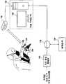
- FIG. 1is a block diagram showing one embodiment of an implant image guide system according to the present invention.
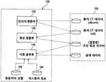
- FIG. 2is a block diagram of one embodiment of a design program executed on the design PC shown in FIG. 1; FIG.
- FIG. 3is a block diagram of one embodiment of the camera sensor shown in FIG. 1;
- FIG. 4is a block diagram of one embodiment of a surgical guide program executed on the surgical guide PC shown in FIG. 1;
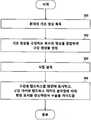
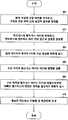
- FIG. 5is a flow chart schematically showing the overall process of the implant surgery guide method according to a preferred embodiment of the present invention.
- FIG 6shows an embodiment of an impression aid.
- FIG. 7is a flowchart specifically showing an embodiment of a process of acquiring a patient base image
- FIG. 10illustrates an example of a second CT image of the structure of FIG. 9
- FIG. 12illustrates an example of a state in which an oral gypsum model of a mandible is placed on a holder for a third CT image in an embodiment
- 15is a flowchart specifically showing an embodiment of an image combining process
- FIG. 16 and 17are diagrams illustrating an example of a combined image of a first vector image and a second vector image.
- FIG. 16is a diagram illustrating an image of an overall appearance including a face
- FIG. 17is related to an impression aid.
- FIG. 19is a flowchart specifically showing one embodiment of a surgical design process
- 20is a view showing an example of a screen displayed by superimposing teeth according to a standard tooth model on a 3D oral image of a patient;
- 21is a view showing an example of a screen for determining a target position and direction of an implant fixture
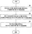
- FIG. 22is a flowchart specifically showing an embodiment of an image guide process for implant fixture placement surgery
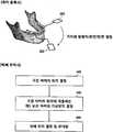
- FIG. 24shows one embodiment of an oral marker attachment tool for attaching an oral marker to the oral cavity
- 25shows an example of an oral marker attachment tool with an impression body attached thereto
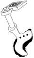
- FIG. 26shows one embodiment of a handpiece marker attachment tool for attaching a handpiece marker to the handpiece
- FIG. 27shows an example of a state in which the handpiece marker is attached to the handpiece via the handpiece marker
- 28is a flow diagram illustrating one embodiment of a method of determining a spatial relationship between an oral cavity and a mouth marker and a spatial relationship between the handpiece and the handpiece marker;
- 29is a view showing a state in which the oral gypsum model is mounted on the holder to which the first auxiliary marker is attached, and the oral marker is attached to the oral gypsum model by the oral marker attachment tool;
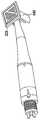
- FIG. 30shows an example of a state in which a second auxiliary marker is attached to a handpiece
- FIG. 31shows an example of a state in which a handpiece marker and a second auxiliary marker are attached to the handpiece
- 32is a view showing an example of images captured by the camera sensor 150 and displayed on the screen during the registration of the marker immediately before the implantation operation and markers therein;
- FIG. 33is a flow chart showing the process of positioning and rendering the maxillary bone during surgery in an embodiment in which only the spatial relationship between the first auxiliary marker and the oral marker is recorded upon marker registration;
- FIG. 34is a flow chart showing the process of positioning and rendering the maxillary bone during surgery in an embodiment in which the coordinates for the jawbone and other oral structures described in the coordinate system of the first auxiliary marker at the time of marker registration are described in the coordinate system of the oral marker;
- FIG. 35is a flow chart showing a modified embodiment of a method for determining the spatial relationship between the oral cavity and the oral markers shown in FIG. 28 and the spatial relationship between the handpiece and the handpiece marker;
- 36is a view showing an example of an output image for a surgical image guide.
- 37is a view showing another example of an output image for the surgical image guide.
- an implant image guide systemincludes a basic image acquisition unit 100, a storage device 110, a design PC 120, a camera sensor 150, A surgical guide PC 160 is provided.
- the base image acquisition unit 100acquires a patient base image of the jawbone and the oral cavity of the patient prior to the implant fixture placement operation (hereinafter, referred to as "placement surgery").
- the base image acquisition unit 100includes a computed tomography (CT) scanner, the patient base image obtained by the base image acquisition unit 100 is for the entire head or skull including the jaw bone of the patient Include CT images.
- the patient basic imagemay include a CT image of an oral gypsum model manufactured based on an impression body obtained from a patient's oral cavity.
- the CT image datamay follow a data format that conforms to the Digital Imaging and Communications in Medicine (DICOM) standard.
- the basic image acquisition unit 100may further include, for example, an optical camera type 3D scanner, in addition to the CT scanner.
- the 3D scan image data output by the 3D scannermay be in a vector-based stereolithography (STL) format.
- STLvector-based stereolithography
- the storage device 110receives and stores image data (hereinafter, referred to as 'basic image data'), ie, CT image and / or 3D scan image data, for the patient basic image from the base image acquisition unit 100.
- the base image datamay be in DICOM format, and at least a part may be in STL format.
- the storage device 110receives and stores the placement design data designed by the design PC 120 as described later.
- the implantation design datais preferably in the STL format, but is not necessarily limited thereto.
- the design PC 120is used to precisely design the target placement of the implant fixture for one or more tooth defect locations based on the basic image data stored in the storage device 110.
- the term 'target placement state'means including a three-axis target position and a three-axis target orientation for each implant fixture.
- the design PC 120stores and executes a design program according to the present invention.
- the design programconverts the format of the data in the DICOM format from the basic image data stored in the storage device 110 into the STL format, and merges two or more images to generate a 3D oral image.
- the design PC 120combines the CT image or the 3D scan image of the dental gypsum model with the head CT image including information about the jawbone and the gum bone to form the 3D oral image.
- the 3D oral imagehas a form in which a precise tooth shape is reinforced on a head CT image.
- the oral cavity image data for the 3D oral cavity imageis stored in the storage device 110.
- the oral cavity image datais preferably in STL format, but is not limited thereto.
- the above-described format conversion and combining operations of the imagemay be regarded as a basic task of arranging the acquired patient basic image data rather than part of the design process. have.
- the design PC 120also allows the designer to design the target placement of the implant fixture based on the three-dimensional oral image.
- the designermay be a dentist, technician, or staff of a dental or design company.
- the design of the target placement statethat is, the target position and the target direction, is selected by the designer placing a virtual tooth with reference to a standard tooth model on a three-dimensional oral image and selecting an appropriate one from various fixtures. This is accomplished by placing the graphic elements for the fixture in the proper direction at the appropriate location in the three-dimensional oral image.
- design worksuch as placement of virtual teeth, selection of fixtures, placement of graphical elements, or the like, may be performed automatically by the design program.
- the placement design datarepresents information on specifications and target arrangements according to the type of fixture, and the data is stored in the storage device 110 to be used for image guide during the surgery.
- the implantation design datais data added in one layer format to the 3D oral image, and thus, a part of the oral image may be configured after the design.
- the following descriptionwill describe the implantation design data as if it is a separate image or image file from the three-dimensional oral image as needed.
- the camera sensor 150continuously detects the position and direction of the oral marker 200 attached to the tooth, jawbone or face of the patient during the implantation operation. At the same time, the camera sensor 150 continuously detects the position and orientation of the handpiece marker 220 attached to the dentist's handpiece 199. The camera sensor 150 provides real-time position and orientation data of the oral marker 200 and the handpiece marker 220 to the surgical guide PC 160 so that the surgical guide PC 160 is provided with the oral marker 200 and the handpiece. Based on the real-time position and orientation data of the marker 220, the jawbone movement and the handpiece movement can be tracked.
- the surgical guide PC 160receives the 3D oral image to which the implantation design data is added from the storage device 110 and stores the 3D oral image in a storage medium such as a hard disk or an SSD provided therein.
- the surgery guide PC 160displays the 3D oral image to which the design data is added on the screen, based on the position and orientation information of the oral marker 200 and the handpiece marker 220 from the camera sensor 150.
- the location of the oral cavity and the handpieceare updated and displayed in real time, and additional information is provided to guide the dentist's implantation operation through the image.
- the surgery guide PC 160stores and executes the surgery guide program according to the present invention.
- the surgery guide programdisplays a three-dimensional oral image, particularly a jawbone image, on the monitor 190 by superposing a target arrangement state of the fixture according to the placement design data.
- the surgical guide programrefers to the handpiece position and orientation information determined based on the position and orientation information of the handpiece marker 220 from the camera sensor 150, and then displays the handpiece on the 3D oral image on the monitor 190. This allows the front ends to overlap.
- the image displayed on the monitor 190includes at least the oral cavity including the jaw bone, the fixture target placement state, and the image portions for the handpiece front end.
- the surgical guide programdetermines the real-time movement of the jawbone based on the position / direction information of the oral marker 200, and moves the jawbone image portion and the fixture arrangement image portion on the monitor 190 according to the determined movement information. Or rotate. Similarly, the surgical guide program determines the real-time movement of the handpiece based on the position / direction information of the handpiece marker 220 and moves and / or rotates the handpiece image portion on the monitor 190 according to the determined motion information. . Accordingly, the surgical guide program allows the image displayed on the monitor 190 to accurately reflect the movement of the jawbone and the handpiece.
- the design program 130includes a data converter 132, an image combiner 134, and an implantation design unit 136.
- the design program 130may include a standard tooth model table 142 and a fixture information table 144.
- the standard tooth model table 142stores statistical position model information for each tooth, the size of each tooth, and the axial direction of each tooth.
- the statistical standard modelmay be a model that is anthropologically and anatomically confirmed and commonly recognized in the dental community, or may be a model accumulated by the system operator of the present invention empirically.
- Fixture table 144stores information about the internal diameter, length, and external shape of commercially available fixtures.
- the data converter 132constantly converts the format of the basic image data of the patient stored in the storage device 110 into, for example, the STL format. Accordingly, all CT data in the DICOM format can be converted to the STL format. In addition, if some of the basic images are acquired by the 3D scanner and are in a format other than STL, such data may also be converted to the STL format.
- the image combiner 134combines two or more three-dimensional images in an STL format into one.
- image combiningis to combine an image of a dental gypsum model with a head CT image that contains information about the jawbone and gum bone, and the combined image obtained through this is a precise tooth on the head CT image.
- the shapehas a reinforced shape. The purpose and specific examples of image combining will be described in detail below.
- the placement design unit 136determines the placement state after placement of the implant fixture, that is, the target placement state, without touching the nerve, considering the location and thickness of the gum bone, based on the three-dimensional oral image of the STL format.
- the implantation design unit 136considers the correspondence relationship between the patient's tooth arrangement and the standard tooth model 142, places a virtual tooth at the position of the tooth to be treated, selects an appropriate one from various fixtures, and selects the selected fixture.
- the graphic element foris placed in the proper direction at the proper position on the 3D oral image. In this process, the placement design unit 136 allows to determine the size or type of the implant fixture within the range of product information in the fixture information table 144.
- the design data determined by the placement design unit 136is stored in the storage device 110 in a form that includes information on a target arrangement state of the implant fixture, that is, information about a target position and a target direction, and specifications data according to the type of fixture. Stored.
- the design program 130performs format conversion, image combining, and design work of the image based on the command input of the designer. However, in other embodiments, the design program may automatically perform image conversion, image combining, and design work.
- FIG. 3shows an embodiment of the camera sensor 150 shown in FIG. 1.
- the camera sensor 150includes a first image sensor 152, a second image sensor 154, a marker detector 156, and a position / direction calculator 158.
- the first and second image sensors 152 and 154constitute a stereoscopic camera, but the present invention is not necessarily limited thereto.
- the first and second image sensors 152 and 154have an oral marker 200 attached to or near the jawbone of the patient and a handpiece marker 220 attached to the dentist's handpiece 199 during the surgery. It is installed to include in, thereby continuously photographing the oral marker 200 and the handpiece marker 220.
- the marker detector 156detects the oral cavity marker 200 and the handpiece marker 220 from the output images of the first and second image sensors 152 and 154.
- the position / direction calculator 158calculates positions and directions of the oral marker 200 and the handpiece marker 220.
- the camera sensor 150repeats the above-described shooting, marker detection, and calculation, and calculates the position and direction information of the oral marker 200 and the handpiece marker 220 calculated in real time. For example, transfer to the surgical guide PC 160 via a USB cable.
- the camera sensor 150is preferably provided with infrared illumination.
- the surgical guide program 170includes a position matching unit 172, a rendering unit 174, a mode selection unit 176, a screen display unit 178, and a voice alarm unit 180.
- the surgical guide program 170may include a handpiece information table 182 that stores information about sizes and specifications of commercially available handpieces and three-dimensional image data.
- the position matching unit 172integrates the three-dimensional oral image portion and the handpiece image portion of the patient in one universal coordinate system, for example, a camera sensor coordinate system, at the beginning of the implantation operation, so as to relate to all image objects displayed on the monitor 190. Allows them to be uniformly represented in coordinates by a single universal coordinate system.
- one universal coordinate systemfor example, a camera sensor coordinate system
- the renderer 174displays the 3D oral cavity image to which the design data is added, on the monitor 190.
- the oral cavity of the patient's oral cavity centered on the jawbone where the implantation operation is performedis enlarged and displayed.
- the rendering unit 174may three-dimensionally display the three-dimensional oral image on the monitor 190 based on the handpiece three-dimensional image data stored in the handpiece information table 182 and the position and orientation information of the handpiece marker 220. Allow handpiece images to be superimposed.
- the rendering unit 174determines the real-time movement of the jawbone based on the position / direction information of the oral marker 200, and moves the jawbone image portion and the fixture arrangement image portion on the monitor 190 according to the determined movement information in real time. And / or rotate. In addition, the rendering unit 174 determines the real-time movement of the handpiece based on the position / direction information of the handpiece marker 220 and moves and / or moves the handpiece image portion on the monitor 190 according to the determined motion information. Rotate Accordingly, the rendering unit 174 allows the image displayed on the monitor 190 to accurately reflect the movement of the jawbone and the handpiece.
- the mode selector 176allows the dentist or hygienist to adjust the view of the image displayed on the screen, and selects additional information to be displayed on the screen.
- the screen display unit 178stores the image data generated by the rendering unit 174 in the frame memory (not shown), so that the image corresponding to the image data stored in the frame memory is displayed on the monitor 190.
- the voice alarm unit 180outputs a warning sound or a guide sound during the surgery according to the operation mode.
- the voice alarm unit 180may be, for example, a speaker, a headphone, or a headset.
- the camera sensor 150 and the surgery guide PC 160are installed in a dental clinic that performs an implantation operation.
- the basic image acquisition unit 100, the storage device 110, and the design PC 120is also installed in the dental clinic to perform the implantation surgery, the patient's jawbone state data acquisition and design process It may be performed in a dental clinic performing an implantation operation.
- the design PC 120may be installed in an external design center, in which case the design work is done by professional designers, and the dental clinic may receive design data over the network. Will be.
- at least a part of the basic image acquisition unit 100for example, a CT scanner may be provided in a separate radiology hospital or a centralized CT imaging center. In this case, the design PC 120 may receive CT image data online from a CT scanner through a network.
- Figure 5schematically shows the overall process of the implant surgery guide method according to a preferred embodiment of the present invention.
- the implant surgery guide methodis based on image information such as cranial three-dimensional images.
- image informationsuch as cranial three-dimensional images.
- CT imagehas information about overall skull structure and jaw bone shape, but one of the most important factors is extracting detailed location and contour of individual teeth from CT image It can be difficult to do. This may be because the CT image may not be clearly displayed with sufficient precision, and in particular, a patient may receive light scattering from the metal prosthesis, which may interfere with precise imaging, because the prosthesis is treated by a metal prosthesis such as gold. Accordingly, it may be difficult to secure necessary information with only one CT scan. Therefore, according to a preferred embodiment, a plurality of patient basic images are obtained and combined to generate a three-dimensional oral image including teeth and jaw bones.
- a basic image of the jawbone and the oral cavity of the patient who is undergoing implantationis acquired.
- the patient base imagecan be obtained by imaging the jawbone and oral cavity of the patient, for example, with a CT scanner. In this case, some of the images may be obtained by the 3D scanner instead of the CT scanner.
- a three-dimensional oral imageis generated by combining a plurality of images constituting the base image.
- Step 304the type of fixture is determined and the target arrangement state of the fixture is determined, so that the type of fixture, the implantation target position and the target direction are performed.
- the implant fixtureWhen the placement design is completed, the implant fixture is placed on the patient, and the handpiece image is displayed on the screen together with the 3D oral image including the fixture target placement state, and the oral marker 200 and the handpiece marker are displayed.
- the operation guide for updating the screen display according to the movement of the markers 200 and 220is performed while tracking the movement of the operation 220 (operation 306).
- steps 300 to 304may be referred to as a preliminary preparation operation for preparing basic data for the surgical guide prior to the implantation operation.
- a plurality of CT imagesare acquired as a patient base image.
- an impression of the patient's teethis obtained.
- the impression aid according to the present inventionis utilized.
- FIG. 6is a photograph showing one embodiment of an impression aid.
- the impression aid tool 320 of FIG. 6is manufactured based on an impression tray used to obtain an impression when a dental prosthesis is manufactured at the dentist, and includes an impression material accommodating part 330 configured to correspond to the teeth.
- a handle 340 extending outwardly from the impression material accommodating part 330is provided.
- the impression material receiving portion 330has an arch-shaped horizontal cross section and extends in the vertical direction and is spaced apart from the inner wall 332 to the outside and has an arch-shaped horizontal cross section and extends in the vertical direction.
- the outer wall 334 and a screen 336connecting upper and lower middle points of the outer wall surface of the inner wall 332 and upper and lower middle points of the inner wall surface of the outer wall 334. Due to the inner wall 332 and the outer wall 334, and the screen 336, the impression material receiving portion 330 has a 'U-shaped' and 'inverted U-shaped' cross-sectional structure, respectively, to receive the impression material
- the upper channel and the lower channelare formed so that the impression can be simultaneously taken for the entire upper and lower teeth.
- Ribs extending in the vertical directionare formed on the outer wall surface of the inner wall 332 and the inner wall surface of the outer wall 334 so that the impression material is moved, separated or minimized during the pulling process.
- the screen 336acts as a retaining base for the impression material and can be made of a nonwoven fabric woven from a sufficiently thin soft board, such as cotton gauze, nylon mesh, or polyether, Minimize the possibility of disturbing the patient's teeth during occlusion, and will not interfere with the correct occlusal impression material.
- the handle 340is attached to the outer wall surface of the outer wall 334 of the impression material container 330.
- the edges of the handle 340preferably include symmetrical and asymmetrical elements, as well as straight lines and curves.
- a ring-shaped protrusion 342is formed to protrude from the handle body in a substantially rectangular parallelepiped form left and right.
- the curved and straight edges of the handle 340serves as a characteristic element for recognizing the spatial position and direction of the faces in the CT image.
- the shape of the handle 340is not limited to that shown in FIG. 6.
- FIG. 7illustrates an embodiment of a process of obtaining a patient basic image in more detail.
- the first CT image of the headis taken while taking the impression of the maxilla and the mandible using the impression aid 320 shown in FIG. 6 (step 360).
- a three-dimensional image of the patient's jawboneis obtained by taking a CT image of the entire skull including the jaw bone, and at this time, the skull may be taken centering on the bone requiring treatment from the maxilla and the mandible.
- the imageis taken while taking the impression of the patient's mouth using the impression aid tool 320 in consideration of the combination with other images.
- the impression materialis sufficiently applied to the upper and lower surfaces of the upper and lower channels of the impression aid tool 320, that is, the screen 336, to the maxilla and the mandible.
- the impressionis taken.
- any suitable impression materialincluding those already available or known, such as alginate, polyvinyl siloxane, polyether, and super-hydrophilic VPS may be used together.
- the imaging of the first CT imagemay be performed after such an impression material is cured or may be performed in the curing process.
- the patientdoes not have to bite the lifting aid 320 so that the handle 340 of the lifting aid 320 is directed to the front, and may be biting in an oblique direction.
- 8shows an example of a first CT image.
- the first CT imageis an image of a face in which the patient is biting the impression assisting tool 320 during the impression acquisition process. From the CT image of the head, if necessary, only the skull without the skin tissue may be extracted from the normal CT image structure.
- the impression aid 320is removed from the patient's mouth. As shown in FIG. 9, the separated impression aid 320 is attached to an impression body in which the upper and lower teeth and the gum of the patient are intaglio.
- a second CT imageis separately photographed with respect to the impression aid having the impression body attached thereto. 10 shows an example of a second CT image of an impression aid with an impression body attached thereto.
- an oral gypsum modelis manufactured and a third CT image is taken.
- the oral gypsum modelmay be made using an impression body manufactured in the process of acquiring the first and second CT images.
- the impressionmay not fully reflect the teeth.
- the patient's teethmay be displaced or distorted while taking impressions and CT scans, and the impression material may be insufficiently filled at the molar area of the edge during the simultaneous impression on the maxilla and the mandible. Accordingly, the impression body manufactured in the process of acquiring the first and second CT images may have low precision.
- a separate impression trayis used to obtain a new impression of the entire tooth in the upper or lower jaw or around the tooth in need of treatment.
- the oral plaster modelis manufactured using the newly manufactured impression body, and CT scan is performed.
- FIG. 11shows an example of an oral gypsum model manufactured using the newly obtained impression body.
- the left sideshows a gypsum model for the upper jaw and the right side shows a gypsum model for the mandible.
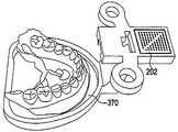
- Figure 12shows an example of a state placed on the cradle oral plaster model for the mandible.
- the shape and size of the holder 370is preferably stored in the design PC 120 shown in FIG. 1 in the form of a three-dimensional image. It is preferable that the auxiliary marker 202 is attached to one point of the holder 370.
- the portion of the holder 370 to which the auxiliary marker 202 is attachedis very similar in shape to the handle 340 in the impression aid tool 320 of FIG. 6, which is an example of the impression aid tool 320 and the holder. This is because the shapes are the same for convenience in order to be able to easily process the 370 in the three-dimensional printer, and the two are not necessarily the same.
- the cradle 370does not have to have a specific shape. However, for the convenience of recognition in the design PC 120, it is preferable that the form of the holder is kept constant. In addition, as will be described later, for convenience in position registration or coordinate integration in the initial stage of the surgical guide, it is preferable that the auxiliary marker 202 is accurately attached at a constant position between each cradle.
- the plaster modelis fixed by attaching and fixing the plaster or other adhesive at an arbitrary position by the operator.
- the object to be photographed in step 364becomes a plaster model attached to the cradle 370 to which the auxiliary marker 202 is attached to one side, and at least a portion of the cradle 370 together. Is photographed.
- the use of ancillary markers and additional features of the cradleare discussed in more detail below in connection with imaging and surgical image guides.
- FIG. 13shows an example of a third CT image of a mandible taken in the state shown in FIG. 12. 14 shows that the cradle portion is removed from the third CT image and only the tooth portion is extracted. As shown, the third CT image shows the teeth and gums of the lower jaw.
- the data converter 132 of the design program 130converts the format of the basic image data of the patient stored in the storage device 110 into, for example, the STL format (step 380). Accordingly, all CT data in the DICOM format can be converted to the STL format. If the first to third CT images are in the dicom format as described above, the data converter 132 converts all of the formats of the first to third CT images into the stl format. In the following description, an image obtained by converting the first to third CT images into the stl format will be referred to as a first to third vector image, respectively.
- the image combiner 134 of the design program 130combines the first to third vector images into one 3D image (step 382).
- the second vector image and the third vector imageare combined using surface shape information of the tooth part.
- teeth and gumsare indented to the inside of the impression body so as to be engraved in the intaglio, so that the vertices of the teeth and the gum parts are converted to emboss.
- the second vector image before the transformationis indented upward from the bottom of the impression body toward the inside of the impression body.
- the second vector image after the vertex transformationis similar to the third vector image in the teeth and the gum parts, and only differs in the precision of the surface bending and the shape of the edge.
- the second vector image and the third vector image after the vertex transformationcan be combined using the surface curvature, that is, the surface shape.
- the verticesthat is, the feature point and the vector, are mainly used for the combination, but it is also possible to combine the characteristic edges or curves together or use only them.
- the handle 340 portion of the impression assisting tool 320 shown in FIG. 6is common, the first vector image and the second vector image are combined using the commonality of the portion of the handle 340.
- FIG. 16 and 17show an example of a combined image of a first vector image and a second vector image.
- FIG. 16is an image of an overall appearance including a face
- FIG. 17is only a layer related to the impression assisting tool 320. This is the extracted video.
- 18shows an example of a combined image of a second vector image and a third vector image.
- the second and third vector imagesare combined in consideration of the vertex conversion process of the second vector image and then combined with the first vector image.
- the combining order of the first to third vector imagesis not limited thereto, and which two images are to be combined first may be arbitrarily determined. That is, after combining the second and third vector images, instead of combining them with the first vector image, the third vector image may be combined after the first and second vector images are combined.
- the facial skin, skull, maxilla and mandible, teeth, gums and gum bonesare displayed.
- the facial skin, skull, maxilla, mandible, and neural tubemay be divided into separate layers and selectively displayed or selectively excluded from display.
- CT images of skullsmay not be enough to extract detailed positions and contours of individual teeth.
- the three-dimensional oral images generated abovehave information on the overall skull structure and jaw bone shape. It has accurate dental information reinforced by gypsum model 3D data.
- the three-dimensional oral imageit is possible to display arbitrary positions in the jaw bone, that is, the maxilla and / or mandible, the oral cavity including the teeth, the gums and the gum bones, and the skull in a single coordinate system.
- the center of the single coordinate system and the direction of each axiscan be arbitrarily determined.
- the auxiliary marker 202may also be used to describe the oral structure.
- itis positioned in a certain direction at a predetermined position, and it is also possible to set the center of the auxiliary marker 202 or any other point on the auxiliary marker 202 as the coordinate system center.
- FIG. 19illustrates in detail an embodiment of a design process for implant fixture placement surgery.
- teeth according to the standard tooth modelare disposed on the 3D oral image of the patient, and the orthodontics of the standard tooth model are adjusted according to the remaining teeth and / or gum bones of the patient (step 380).
- FIG. 18shows an example of a screen displaying teeth superimposed on a standard tooth model on a 3D oral image of a patient. Orthodontic adjustment of the standard tooth model may be performed by dragging the vertex or control point illustrated in FIG. 20 with a mouse.
- a standard tooth positioned on the standard tooth modelis disposed at a tooth defect position requiring implant placement (step 382).
- the position of the neural tube in the jaw boneis checked (step 384).
- the location of the neural tubecan be checked from the first CT image, and as described above, the neural tube can be selectively displayed or selectively excluded from the display by being separated into a separate layer from the facial skin, skull, maxilla, and mandible in the three-dimensional oral image. have.
- the target position and direction of the implant fixtureare determined.
- the determination of the target position and orientation of the implant fixtureis made by moving or rotating the implant fixture within the screen.
- the central axis of the fixtureshould not be aligned with the central axis of the standard tooth placed in step 382 or at least significantly off the standard tooth, and the fixture should not touch the neural tube. In other words, it should be placed in the jaw stably without being exposed to the inner or outer wall of the jaw bone. If the jaw is thin or likely to interfere with the neural tube, change the thickness and / or length of the fixture.
- 21shows an example of a screen for determining a target position and a target direction of an implant fixture.
- reference numeral 390denotes a neural tube
- 392denotes an implant fixture.
- the placement design data indicating information on the specifications, the exact placement target position and the target direction according to the type of fixtureis stored in the storage device 110.
- the information about the target position and the target orientation of the implantationis added to the three-dimensional oral image in one layer form, and thus constitutes a part of the designed three-dimensional oral image.
- FIG 22illustrates in detail an embodiment of an image guide process for implant fixture placement surgery.
- the oral markeris attached to a nearby structure or face (hereinafter, referred to as the “oral cavity”) such as a jawbone or a tooth of a patient, and the spatial relationship between the jawbone or the oral cavity and the oral marker is determined.
- the term 'spatial relationship'refers to a relative position and relative direction, that is, a parameter representing information for knowing the position and direction of another object when the position and direction of one object are known.
- the handpiece markeris attached to the handpiece used by the dentist and the spatial relationship between the handpiece and the handpiece marker is determined.
- the markersare all formed in the form of a plurality of dots arranged in a square border.
- Each markerhas a different arrangement pattern of dots, and is used in a predefined state in which pattern of markers are used as oral markers, handpiece markers, and first and second auxiliary markers described below.
- the center of the squareis defined as the origin, the x-axis passing through the origin and parallel to one edge, the y-axis being rotated by 90 degrees around the origin, and the direction emerging from the marker.
- the coordinate system of each markercan be determined by setting the z-axis.
- the oral marker and the handpiece markerare attached to the oral cavity and the handpiece, respectively, using separate tools.
- the oral marker attachment tool 600is coupled to the teeth of the patient 602 and extends outward from the engagement 604 to be partially exposed outside the lips of the patient.
- the above link arm 608is provided.
- a plurality of through holes 602amay be formed in the coupling part 602.
- the oral marker attachment tool 600is preferably processed into a plastic material to minimize weight.
- the impression materialis applied to one surface of the coupling part 602, and then the jawbone (for example, the dental site to be implanted) to be operated on the patient's mouth is maxillary.
- the jawbonefor example, the dental site to be implanted
- the impression materialis cured, the impression material that is hardened by the impression material is firmly attached to the coupling part 602 so as not to fall off.
- the impression materialpenetrates into the plurality of through holes 602a formed in the coupling part 602 and is pulled up.
- the coupling force between the sieve and the coupling portion 602is higher.
- the adhesion between the tooth and the impression bodyis high, so unless the intentional separation by applying an external force oral marker attachment tool 600 maintains the state attached to the tooth via the impression body.
- the adhesion statemay be maintained, and the adhesion state may be maintained even when the oral marker attachment tool 600 is attached to the corresponding position of the oral gypsum model.
- 25shows a state in which the impression body is detached from the tooth of the oral marker attachment tool 600.
- itmay be adhered to the oral gypsum model and attached to the oral cavity after curing is completed.
- the ball joints 606 and 610 and the link arm 608may be removed so as not to impede the operation of the dentist or the hygienist or the operation of the system according to the present invention. Can be adjusted to select the optimal position. Accordingly, the oral marker 200 or the oral marker attachment tool 600 obstructs the dentist's field of view, interferes with the access or use of the handpiece, prevents the hygienist from using the inhaler, or the oral marker 200. Is prevented from being pushed to the lips of the patient, can be easily separated in an emergency, there is an advantage that can be seen well in the camera sensor 150.
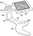
- FIG. 26shows one embodiment of a handpiece marker attachment tool for attaching the handpiece marker to the handpiece.
- the handpiece marker attachment tool 620includes a clip 622 attached to the side of the handpiece, a marker attachment panel 628 to which the handpiece marker 220 is attached, and the clip 622 And one or more link arms 624 and one or more ball joints 626 connecting the marker attachment panel 628.
- Handpiece marker attachment tool 620is also preferably processed into a plastic material to minimize weight.
- Such oral marker attachment tool 600can be easily attached by fitting to the outer side of the handpiece.
- 27shows an example of a state in which the handpiece marker is attached to the handpiece through the handpiece marker.
- the handpiece marker 220 or the handpiece marker attachment tool 620After attaching the handpiece marker 220 to the handpiece by the handpiece marker attachment tool 620, the link arm 624 and the ball joint so as not to interfere with the work of the dentist or hygienist or the operation of the system according to the present invention. Adjust 626 to select the optimal position state. Accordingly, the handpiece marker 220 or the handpiece marker attachment tool 620 obstructs the dentist's field of view, interferes with the access or use of the handpiece, prevents the hygienist from using the inhaler, or 200 can be prevented from being pushed to the lips of the patient, can be easily separated in an emergency, there is an advantage that can be seen well in the camera sensor 150.
- the handpiece marker 220can be tracked to precisely track where the handpiece is located, and the oral marker 200 By tracking the movement of the jawbone surgery is performed, the handpiece and jawbone reflecting the movement can be displayed on the screen in real time.
- a 3D oral image to which implant design data is addedis displayed on the monitor 190 screen of the surgery guide PC 160 (operation 404).
- the camera sensor 150continuously detects the positions and directions of the oral marker 200 and the handpiece marker 220 and provides them to the surgical guide PC 160 (step 406).
- the data provided by the camera sensor 150 to the surgical guide PC 160is a three-dimensional position, i.e., x-axis, y-axis, for the oral marker 200 and the handpiece marker 220, respectively. , six data of the position in the z-axis direction and the rotation angle with respect to the three-dimensional direction, that is, the x-axis, the y-axis, and the z-axis.
- the surgical guide program executed on the surgical guide PC 160determines the precise jaw bone, ie, the position of the maxillary or mandible, on which the surgery is performed, which reflects the movement of the jawbone from the position and direction of the oral marker 200, and updates the displayed image on the screen.
- the precise position of the handpiece reflecting the movement of the handpieceis determined from the position and the direction of the handpiece marker 220, and the display of the handpiece portion is updated on the screen (step 408).
- the required movement and rotation of the handpiecemay be actively guided through the screen or through the screen and the headset speaker ( Step 410).
- the oral cavity and the oral markersThe spatial relationship between and the spatial relationship between the handpiece and the handpiece marker should be clearly understood.
- FIG. 28shows one embodiment of a method of determining the spatial relationship between the oral cavity and the oral marker and the spatial relationship between the handpiece and the handpiece marker.
- the oral markeris attached to the oral gypsum model in the same manner as the oral marker is attached to the oral cavity in a state where the first auxiliary marker is attached in a state where the positional relationship with the oral gypsum model is clearly known ( Step 420).
- the oral gypsum model on the cradle 370 described with reference to FIG. 12is utilized. That is, as shown in FIG. 12, in the state where the oral gypsum model is mounted on the holder 370, if the shape is the same between the holders and the first auxiliary marker 202 is correctly attached at a predetermined position, the third CT image or the third 3 It is possible to detect the exact position and shape of the plaster model relative to the cradle 370 in the vector image, and the relationship between the cradle 370 and the first auxiliary marker 202 is clear, so that the cradle 370 may be mediated.
- FIG. 22shows a state in which an oral gypsum model is mounted on a holder 370 to which the first auxiliary marker 202 is attached, and the oral marker 200 is attached to the oral gypsum model by the oral marker attachment tool 600. .
- the second auxiliary markeris attached to the handpiece in a state where the positional relationship with the handpiece is clearly understood.
- the second auxiliary marker 222may be attached to the top surface of the handpiece that meets the central axis extension of the drilling tool in the handpiece.
- the handpiece marker 220is mounted to the handpiece by the handpiece marker attachment tool 620.
- FIG. 31shows an example in which the handpiece marker 220 and the second auxiliary marker 222 are attached to the handpiece.
- the oral marker 200, the handpiece marker 220, and the first and second auxiliary markers 202 and 222may be connected to the stereoscopic cameras of the camera sensor 150.
- the image sensordetects the image, and determines the spatial relationship between the oral marker 200 and the first auxiliary marker 202 and the spatial relationship between the handpiece marker 220 and the second auxiliary marker 222.
- the camera sensor 150distinguishes which marker is each marker according to the arrangement pattern of the points in the marker.
- the camera sensor 150restores the points in the marker in three dimensions for each marker, calculates the position and direction of the marker based on the camera coordinate system, and calculates the position data and the orientation data for each marker. Transfer to PC 160.
- the surgical guide PC 160determines the spatial relationship between the oral marker 200 and the first auxiliary marker 202, that is, the distance and the amount of rotation, and the distance between the handpiece marker 220 and the second auxiliary marker 222. Also determine the amount of rotation. The calculation of the spatial relationship between the markers may be made in the camera sensor 150 rather than the surgical guide PC 160.
- the oral cavity and the oral marker 200are defined.
- the spatial relationship between themcan be seen.
- each structure in the oral cavityis described in the coordinate system of the first auxiliary marker 202
- each structure in the oral cavityis represented using the spatial relationship between the oral marker 200 and the first auxiliary marker 202. It is described by the coordinate system of and can be rendered to the camera viewpoint or other viewpoint while reflecting the movement of the jawbone.
- the spatial relationship between the handpiece marker 220 and the second auxiliary marker 222is determined, the spatial relationship between the handpiece and the second auxiliary marker 222 is already established, so the handpiece and handpiece marker The spatial relationship between the 220 can be seen.
- each point on the handpieceis described in the coordinate system of the second auxiliary marker 222, each point on the handpiece is represented using the spatial relationship between the handpiece marker 220 and the second auxiliary marker 222.
- the handpiececan be rendered to a camera viewpoint or other viewpoint while reflecting the movement of the handpiece.
- Steps 420 to 424 of FIG. 28may be simply performed as a registration or marker registration procedure of the markers immediately before the fixture placement surgery for the patient.
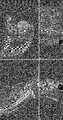
- 32shows images captured by the camera sensor 150 and displayed on the screen in the registration process of the marker immediately before the implantation operation and the markers therein.
- the left siderepresents an image acquired by the first image sensor
- the right siderepresents an image acquired by the second image sensor.
- the directions of the first auxiliary marker 202, the oral marker 200, the second auxiliary marker 222, the handpiece marker 220, and the first auxiliary marker 202 and the oral cavityare obtained using two images.
- the spatial relationship between the markers 200 and between the second auxiliary marker 222 and the handpiece marker 220may be detected.
- FIG. 33is a diagram illustrating the spatial relationship between the first auxiliary marker 202 and the oral marker 200 at the time of registering a marker, that is, only distance and direction difference (rotation angle), and recording and ending the jaw bone during surgery. And the rendering process.
- the position of the oral marker 200is determined in operation (operation 440)
- the vector corresponding to the process of determining the virtual position of the second auxiliary marker 202 corresponding to the position of the oral marker 200is determined.
- the jawbone position corresponding to the virtual position of the second auxiliary marker 202is determined and rendered (operation 444).
- the jawbone positioning and rendering process during the surgeryis shown.
- the jawbone position corresponding to the position of the oral marker 200is immediately determined by using the location information re-described as the jawbone position. It becomes possible to render (step 462).
- FIG. 35shows a modified embodiment of a method for determining the spatial relationship between the oral cavity and the oral markers shown in FIG. 28 and the spatial relationship between the handpiece and the handpiece marker.
- the oral marker 200is attached to the oral gypsum model in the same manner as the oral marker 200 is attached to the oral cavity (step 480). That is, as shown in FIG. 22, the oral marker attachment tool 600 having the impression body is attached to the oral gypsum model in close contact, and attached at a position corresponding to the attachment position in the oral cavity.
- the oral gypsum model to which the oral marker 200 is attachedis photographed by the stereoscopic camera or two image sensors of the camera sensor 150, and coordinates of a plurality of points on the oral gypsum model are determined by the oral marker 200.
- the coordinates of the entire oral cavityare described using the coordinate system of the oral gypsum model and the oral cavity in the coordinate system of the oral marker 200 (step 482).
- the handpiece markeris attached to the handpiece using the handpiece marker attachment tool 620 shown in FIG. 24 (step 484).
- the handpiece to which the handpiece marker 220 is attachedis photographed by the stereoscopic camera or two image sensors of the camera sensor 150, and coordinates of the plurality of points on the handpiece are displayed on the handpiece marker 220.
- the coordinate systemis described (step 486).
- the output image for the surgical image guide of the surgical guide program 170may be in various forms.
- a screenmay be divided into a plurality of viewports to display a perspective view, a front view, a top view, and a side view in each viewport, or only a perspective view may be displayed in a single viewport.
- the viewpoint to be renderedmay be a camera viewpoint, or may be a dentist's viewpoint automatically detected and set by a program or set by a dentist.
- the magnification of the imagemay vary dynamically depending on the stage of surgery or the range of movement of the handpiece, or may maintain a fixed magnification. Also, in rendering the handpiece, it is possible to render the entire handpiece, but it is also possible to simply render only the drilling tool portion.
- Additional reference informationmay also vary according to the screen setting and the user input. For example, the required amount and direction of movement of the handpiece and the required amount and amount of rotation can be displayed. In addition, the depth in which the drilling is performed and / or the remaining depth may be displayed while the drilling is performed. If necessary, a warning sound or a guide sound may be output. The sound information may be output only to earphones, headphones, or a headset so as to relieve anxiety of the patient.
- each viewportdisplays a perspective view, a front view, a top view, and a side view.
- Each viewportcan display an image enlarged around the design fixtures 900 and 900b and the handpiece 920.
- the handpiece 920has only a front end portion, that is, a drilling tool portion. Can be rendered.
- the screencontains only a single viewport, in which the perspective view of the camera view or dentist view is displayed.
- the fixture 900 and the handpiece 920 of the designmay be centrally displayed, and the required amount and direction of movement of the handpiece 920 and the required amount of rotation and rotation may be displayed.
- the camera sensor 150has been described with reference to an embodiment having two image sensors, the present invention is not limited thereto, and the camera sensor may include only one image sensor.
- the design program 130 executed in the design PC 120may not be a single program but a collection of several programs.
- some process stepsmay be performed by known commercial programs.
- the operation of combining the first to third vector imagesmay be performed using an existing image processing program having a merging function, for example, a DAVID program produced and sold by David Vision System GmbH of Germany.
- the conversion of the image of the dicom format into the stl formatmay be performed by a program used for CT image processing.
Landscapes
- Health & Medical Sciences (AREA)
- Life Sciences & Earth Sciences (AREA)
- Oral & Maxillofacial Surgery (AREA)
- Animal Behavior & Ethology (AREA)
- General Health & Medical Sciences (AREA)
- Public Health (AREA)
- Veterinary Medicine (AREA)
- Dentistry (AREA)
- Surgery (AREA)
- Epidemiology (AREA)
- Engineering & Computer Science (AREA)
- Biomedical Technology (AREA)
- Nuclear Medicine, Radiotherapy & Molecular Imaging (AREA)
- Heart & Thoracic Surgery (AREA)
- Medical Informatics (AREA)
- Molecular Biology (AREA)
- Robotics (AREA)
- Orthopedic Medicine & Surgery (AREA)
- Biophysics (AREA)
- Pathology (AREA)
- Physics & Mathematics (AREA)
- Optics & Photonics (AREA)
- Dental Prosthetics (AREA)
- Dental Tools And Instruments Or Auxiliary Dental Instruments (AREA)
- Apparatus For Radiation Diagnosis (AREA)
Abstract
Description
Translated fromKorean본 발명은 의료 영상의 생성 및 표시 방법에 관한 것으로서, 특히, 치과에서의 치료를 지원하기 위한 영상 생성 및 표시 방법에 관한 것이다.The present invention relates to a method for generating and displaying a medical image, and more particularly, to a method for generating and displaying an image for supporting a treatment in a dentist.
치과 보철치료의 일종인 임플란트 시술을 행함에 있어서는, 티타늄과 같은 금속으로 제작되는 인공치근인 임플란트 픽스츄어(Implant Fixture, 이하 '픽스츄어'로 약칭함)를 치조골에 식립하여 골조직과 융합되도록 한 후, 상기 임플란트 픽스츄어에 임플란트 어버트먼트(Implant Abutment, 이하 '어버트먼트'로 약칭함)를 나사(Abutment Screw)에 의해 체결한 다음, 상기 어버트먼트 상에 인공치관 즉, 크라운 또는 브릿지를 부착하게 된다. 상기 어버트먼트는 인공치관을 픽스츄어에 연결시키고, 인공치관에 가해지는 힘을 픽스츄어를 통해 턱뼈로 전달하는 역할을 한다.In performing the implant procedure, a kind of dental prosthetic treatment, an implant fixture (abbreviated as 'fixture'), which is an artificial tooth made of a metal such as titanium, is placed in the alveolar bone to be fused with bone tissue. After the implant abutment (abbreviated as 'abutment') is fastened to the implant fixture by an abutment screw, an artificial crown, that is, a crown or a bridge, is mounted on the abutment. Will be attached. The abutment connects the artificial crown to the fixture and serves to transfer the force applied to the artificial crown to the jawbone through the fixture.
그런데 이와 같은 임플란트 보철치료에서, 픽스츄어 식립위치를 잘 결정하고 올바른 방향으로 필요한 깊이까지 드릴링을 행하여, 픽스츄어를 정확히 식립하는 데에는 고도의 전문성이 요구된다. 픽스츄어의 식립위치, 방향 또는 깊이가 미미하게 잘못된 경우에는 해당 환자에게 적합화된 개인화 어버트먼트(Customized Abutment)를 제작, 사용함으로써 오류를 보완할 수 있지만, 오류가 큰 경우에는 임플란트 보철물의 기능성과 심미성이 현저히 저하될 수 있다.However, in such an implant prosthesis treatment, a high degree of expertise is required to accurately determine the placement of the fixture and to drill the required depth in the right direction, thereby accurately placing the fixture. If the fixation position, direction or depth of the fixture is insignificantly misaligned, the error can be compensated by making and using a customized abutment adapted to the patient, but in the case of a large error, the functionality of the implant prosthesis And aesthetics can be significantly reduced.
이에 따라 임플란트 치료는 경험많은 일부 치과의사들만이 시술하고 있으며, 이러한 현상은 치료비가 낮아지는 것에 대한 장애로 작용하고 있다. 한편, 경험많은 치과의사들의 경우에도 실수를 범할 수 있기 때문에, 현재 시술 중인 작업이 제대로 이루어지고 있는지 확인할 수 있는 방안이 요구되고 있지만, 아직까지는 이러한 확인 및/또는 검증 방안이 없다.As a result, implant treatment is performed only by some experienced dentists, and this phenomenon acts as a barrier to lower treatment costs. On the other hand, since even experienced dentists can make mistakes, there is a need for a method for confirming whether the current operation is being performed properly, but there is no such confirmation and / or verification method.
본 발명은 이와 같은 문제점을 해결하기 위한 것으로서, 임플란트 시술 중에 시술자에게 픽스츄어의 식립위치와 방향 및 깊이 등을 영상으로 가이드함으로써, 오류 발생 가능성을 크게 저감하고 시술자로 하여금 올바르게 시술이 이루어지고 있다는 확신을 심어줄 수 있는 임플란트 수술 가이드 방법을 제공하는 것을 그 기술적 과제로 한다.The present invention is to solve such a problem, by guiding the implantation position, direction and depth of the fixture to the operator during the implant procedure, greatly reducing the possibility of error and ensures that the procedure is performed correctly It is a technical task to provide a guide method for implant surgery that can be implanted.
상기 기술적 과제를 달성하기 위한 본 발명의 임플란트 수술 가이드 방법은 (a) 환자에 대한 3차원 구강 영상을 생성하는 단계; (b) 3차원 구강 영상을 토대로 임플란트 픽스츄어의 목표 위치 및 목표 방향을 포함하는 목표 배치상태를 설계하는 단계; (c) 제1 패턴을 포함하는 구강 마커를 환자의 턱뼈 또는 그 주변 신체에 부착하고, 구강 마커와 상기 턱뼈의 공간적 관계를 결정하며, 제2 패턴을 포함하는 핸드피스 마커를 치과의사의 핸드피스에 부착하고, 핸드피스 마커와 핸드피스의 공간적 관계를 결정하는 단계; 및 (d) 구강 마커와 상기 핸드피스 마커의 움직임을 추적하면서, 구강 마커 및 핸드피스 마커의 위치와 방향 변화를 토대로 턱뼈와 핸드피스의 위치와 방향을 추정하고, 턱뼈와 핸드피스의 실시간 위치/방향 변화를 반영한 턱뼈 영상 부분과 핸드피스 영상 부분을 화면에 표시하는 단계;를 구비한다.Implant surgery guide method of the present invention for achieving the above technical problem comprises the steps of (a) generating a three-dimensional oral image of the patient; (b) designing a target placement state including a target position and a target direction of the implant fixture based on the three-dimensional oral image; (c) attaching the oral marker comprising the first pattern to the patient's jawbone or body around it, determining the spatial relationship between the oral marker and the jawbone, and handpiece marker comprising the second pattern with the dentist's handpiece Attaching to and determining a spatial relationship of the handpiece marker and the handpiece; And (d) tracking the movement of the oral marker and the handpiece marker, estimating the position and orientation of the jawbone and the handpiece based on the changes in the position and orientation of the oral marker and the handpiece marker, And displaying the jawbone image portion and the handpiece image portion reflecting the change of direction on the screen.
일 실시예에 있어서, 상기 (a)단계는 상기 환자의 상기 턱뼈를 포함한 구강 내부에 대한 적어도 하나의 기초 영상을 획득하는 단계; 상기 환자의 구강 석고 모형을 제작하고, 상기 구강 석고 모형에 대한 석고모형 영상을 획득하는 단계; 및 상기 적어도 하나의 기초 영상과 상기 석고모형 영상을 결합하여 상기 3차원 구강 영상을 생성하는 단계;를 구비한다.In an embodiment, the step (a) may include obtaining at least one basic image of the inside of the mouth including the jaw bone of the patient; Preparing an oral gypsum model of the patient and obtaining a gypsum model image of the oral gypsum model; And generating the 3D oral cavity image by combining the at least one base image and the plaster model image.
일 실시예에 있어서, 상기 (a)단계는 일부가 구강 외부로 노출되는 인상 보조 도구에 인상재를 도포한 후 상기 환자가 치아로 상기 인상재가 도포된 부분을 물도록 하고, 제1 기초 영상을 획득하는 단계; 상기 인상재가 경화된 인상체가 부착되어 있는 상기 인상 보조 도구에 대하여 제2 기초 영상을 획득하는 단계; 및 상기 환자의 구강 석고 모형을 제작하고, 상기 구강 석고 모형에 대한 제3 기초 영상을 획득하는 단계;를 구비한다. 여기서, 상기 (a)단계는 상기 제1 내지 제3 기초 영상을 결합하여 상기 3차원 구강 영상을 생성하는 단계;를 더 구비할 수도 있다.In one embodiment, the step (a) is after applying the impression material to the impression aid is exposed to the outside of the mouth portion so that the patient bites the portion of the impression material is applied to the teeth, to obtain a first basic image Making; Acquiring a second basic image of the impression assisting tool to which the impression member on which the impression material is cured is attached; And preparing an oral gypsum model of the patient and acquiring a third basic image of the oral gypsum model. Here, the step (a) may further comprise the step of generating the three-dimensional oral image by combining the first to third base image.
제1 내지 제3 기초 영상 중 적어도 일부가 CT 영상인 경우에는, 제1 내지 제3 기초 영상 중에서 CT 영상으로 된 영상을 벡터 영상으로 변환하여, 제1 내지 제3 기초 영상으로부터 제1 내지 제3 벡터 영상을 결정하고, 제1 내지 제3 벡터 영상을 결합하여 3차원 구강 영상을 생성하는 것이 바람직하다.When at least a part of the first to third base images is a CT image, the CT image from among the first to third base images is converted into a vector image, and the first to third base images are converted from the first to third base images. It is preferable to determine a vector image and to generate a 3D oral image by combining the first to third vector images.
제1 내지 제3 벡터 영상을 결합하여 3차원 구강 영상을 생성하는 과정에서, 제1 및 제2 벡터 영상은 제1 및 제2 벡터 영상 내에서 인상 보조 도구에 대응하는 부분을 이용하여 결합되고, 제2 및 제3 벡터 영상은 치아 부분의 표면형상 정보를 이용하여 결합될 수 있다.In the process of combining the first to third vector images to generate a three-dimensional oral image, the first and second vector images are combined using a portion corresponding to the impression aid in the first and second vector images, The second and third vector images may be combined using surface shape information of the tooth part.
제1 내지 제3 벡터 영상을 결합하여 3차원 구강 영상을 생성함에 있어서는,In combining the first to third vector images to generate a three-dimensional oral image,
제2 벡터 영상에서 상기 인상체 부분에 대하여 버텍스를 변환하여 음각을 양각으로 변환하고, 제2 벡터 영상에서 양각으로 변환된 치아 부분을 제3 벡터 영상의 대응하는 치아 부분과 결합하는 것이 바람직하다.In the second vector image, it is preferable to convert the intaglio to the emboss by converting the vertices with respect to the impression part, and to combine the tooth part converted into the emboss in the second vector image with the corresponding tooth part of the third vector image.
식립 예정 위치를 설계함에 있어서는, 먼저 3차원 구강 영상에 소정의 표준치아 모형에 따른 치아들을 배치하고 상기 표준치아 모형의 치열을 조정한 다음, 임플란트 픽스츄어의 식립이 필요한 치아결손 위치에 표준치아 모형에 따른 표준치아를 배치한 후, 턱뼈 내에 있는 신경관에 저촉되지 않고 턱뼈의 외부로 노출되지 않도록 하면서 임플란트 픽스츄어의 식립 예정 위치를 결정하는 것이 바람직하다. 식립 예정 위치를 결정할 때, 식립할 임플란트 픽스츄어의 종류를 함께 결정하고, 식립 예정 위치에 관한 설계 데이터를 영상 요소의 형태로 3차원 구강 영상에 부가하는 것이 바람직하다.In designing the position to be placed, first, teeth according to a predetermined standard tooth model are placed on a three-dimensional oral image, the teeth of the standard tooth model are adjusted, and then a standard tooth model is placed at the position of the tooth defect that needs to be implanted. After placing the standard tooth according to the present invention, it is desirable to determine the placement position of the implant fixture while avoiding contact with the neural tube in the jawbone and exposing to the outside of the jawbone. When determining the position to be implanted, it is desirable to determine the type of implant fixture to be implanted together and to add design data about the position to be implanted to the three-dimensional oral image in the form of an image element.
구강 마커를 환자의 구강에 부착할 때에는, 하나 이상의 볼 조인트 및 하나 이상의 링크 아암과 상기 구강 마커를 부착하기 위한 마커 부착부를 구비하는 구강 마커 부착 도구를 사용하여 부착하는 것이 바람직하다. 또한, 핸드피스 마커를 핸드피스에 부착할 때에도, 하나 이상의 볼 조인트 및 하나 이상의 링크와 상기 핸드피스 마커를 부착하기 위한 마커 부착부를 구비하는 핸드피스 마커 부착 도구를 사용하여 부착하는 것이 바람직하다.When attaching the oral marker to the oral cavity of a patient, it is desirable to attach using an oral marker attachment tool having at least one ball joint and at least one link arm and a marker attachment for attaching the oral marker. Also, when attaching the handpiece marker to the handpiece, it is desirable to attach using a handpiece marker attachment tool having at least one ball joint and at least one link and a marker attachment for attaching the handpiece marker.
상기 구강 마커를 부착하는 것과 관련하여, 3차원 구강 영상을 생성하는 단계는 (a1) 일부가 구강 외부로 노출되는 인상 보조 도구에 인상재를 도포한 후 상기 환자가 치아로 상기 인상재가 도포된 부분을 물도록 하고, 제1 기초 영상을 획득하는 단계; (a2) 인상재가 경화된 인상체가 부착되어 있는 인상 보조 도구에 대하여 제2 기초 영상을 획득하는 단계; (a3) 상기 환자의 구강 석고 모형을 제작하고, 구강 석고 모형을 소정의 형태와 크기를 가지는 거치대에 거치하고 촬영하여 구강 석고 모형에 대한 제3 기초 영상을 획득하는 단계; 및 (a4) 제1 내지 제3 기초 영상을 결합하여 상기 3차원 구강 영상을 생성하는 단계;를 구비할 수 있다.In connection with attaching the oral marker, the step of generating a three-dimensional oral image may include (a1) applying an impression material to an impression aid that is partially exposed to the outside of the oral cavity, and then applying the impression material to the tooth by the patient. Biting and obtaining a first basic image; (a2) acquiring a second basic image of an impression assisting tool to which an impression member having a hardened impression material is attached; (a3) preparing the oral gypsum model of the patient, and mounting and photographing the oral gypsum model on a holder having a predetermined shape and size to obtain a third basic image of the oral gypsum model; And (a4) combining the first to third basic images to generate the 3D oral image.
이와 같은 상태에서 구강 또는 3차원 구강 영상 내에 있는 각 점의 좌표를 좌표로 정밀하게 표시하고 추적할 수 있도록, 환자의 구강에서 구강 마커가 부착되는 부위에 대응하는 구강 석고 모형의 부위에 구강 마커를 부착하는 것이 바람직하다. 이때, 상기 거치대에서 소정의 위치에는 제1 보조 마커를 부착되어 있는 것이 바람직한데, 제1 보조 마커는 구강 마커가 부착되는 시기를 전후하여 부착될 수도 있고, 제3 기초 영상을 획득하기 이전에 미리 부착되어 있을 수도 있다.In this state, oral markers are placed on the site of the oral gypsum model corresponding to the area where the oral marker is attached to the oral cavity of the patient so that the coordinates of each point in the oral cavity or 3D oral image can be precisely displayed and tracked. It is preferable to attach. In this case, it is preferable that the first auxiliary marker is attached to a predetermined position in the holder. The first auxiliary marker may be attached before and after the time when the oral marker is attached, and before the third basic image is acquired. It may be attached.
제1 보조 마커와 구강 마커가 구강 석고 모형에 부착된 상태에서, 제1 보조 마커와 구강 마커를 카메라로 촬영하여 이 마커들 간의 공간적 관계를 결정할 수 있다.In a state where the first auxiliary marker and the oral marker are attached to the oral plaster model, the first auxiliary marker and the oral marker may be photographed with a camera to determine the spatial relationship between the markers.
제1 보조 마커와 구강 마커 간의 공간적 관계를 알게 되면, 구강 마커의 위치와 방향을 검출하였을 때, 제1 보조 마커와 구강 마커의 공간적 관계를 토대로 하여, 구강 마커의 위치 검출량과 방향 검출량으로부터 턱뼈의 위치를 추정하는 것이 가능해진다.When the spatial relationship between the first auxiliary marker and the oral marker is known, when the position and the direction of the oral marker are detected, the jawbone is determined from the position detection amount and the direction detection amount of the oral marker based on the spatial relationship between the first auxiliary marker and the oral marker. It becomes possible to estimate the position.
3차원 구강 영상과 핸드피스를 화면에 표시함에 있어서는, 3차원 구강 영상을 카메라의 시점 또는 치과의사의 시점에서 렌더링할 수도 있다. 이 때, 핸드피스의 필요 이동량 및 이동방향과, 필요 회전량 및 회전방향을 추가적으로 표시할 수도 있다. 또한, 드릴링이 진행된 깊이 또는 남은 깊이를 화면에 추가적으로 표시할 수도 있다.In displaying the 3D oral cavity image and the handpiece on the screen, the 3D oral cavity image may be rendered from the camera's viewpoint or the dentist's perspective. At this time, the required moving amount and the moving direction of the handpiece, and the required rotating amount and the rotating direction may be further displayed. In addition, the depth in which drilling is performed or the remaining depth may be additionally displayed on the screen.
본 발명의 임플란트 수술 가이드 방법은 기록매체에 적재되어 데이터 처리장치에 의해 실행될 수 있는 프로그램을 토대로 구현될 수 있다.The implant surgical guide method of the present invention may be implemented based on a program loaded on a recording medium and executed by a data processing apparatus.
본 발명에 따르면, 임플란트 시술 중에 시술자에게 픽스츄어의 식립위치와 방향 및 깊이 등을 안내함으로써, 오류 발생 가능성을 크게 저감하고 시술자로 하여금 올바르게 시술이 이루어지고 있다는 확신을 심어줄 수 있게 된다.According to the present invention, the implantation position, direction, and depth of the fixture is guided to the operator during the implantation procedure, thereby greatly reducing the possibility of error and giving the operator the confidence that the procedure is performed correctly.
이에 따라 정확한 시술이 이루어질 수 있도록 함과 아울러, 임플란트 시술을 행할 수 있는 치과의사의 숫자를 증대시킬 수 있고, 각 치과의사의 치료 생산성을 높일 수 있게 되며, 치료비 인하를 기대할 수 있게 된다는 효과가 있다.As a result, accurate procedures can be performed, and the number of dentists who can perform implant procedures can be increased, treatment productivity of each dentist can be increased, and treatment costs can be expected to be lowered. .
이하, 첨부된 도면을 참조하여 본 발명의 바람직한 실시예를 보다 구체적으로 설명한다. 도면 중,Hereinafter, with reference to the accompanying drawings will be described in detail a preferred embodiment of the present invention. In the drawings,
도 1은 본 발명에 의한 임플란트 이미지 가이드 시스템의 일 실시예를 보여주는 블록도;1 is a block diagram showing one embodiment of an implant image guide system according to the present invention;
도 2는 도 1에 도시된 설계용 PC에서 실행되는 설계 프로그램의 일 실시예의 블록도;FIG. 2 is a block diagram of one embodiment of a design program executed on the design PC shown in FIG. 1; FIG.
도 3은 도 1에 도시된 카메라 센서의 일 실시예의 블록도;3 is a block diagram of one embodiment of the camera sensor shown in FIG. 1;
도 4는 도 1에 도시된 수술 가이드 PC에서 실행되는 수술 가이드 프로그램의 일 실시예의 블록도;4 is a block diagram of one embodiment of a surgical guide program executed on the surgical guide PC shown in FIG. 1;
도 5는 본 발명의 바람직한 실시예에 따른 임플란트 수술 가이드 방법의 전체적인 공정을 개략적으로 보여주는 흐름도;5 is a flow chart schematically showing the overall process of the implant surgery guide method according to a preferred embodiment of the present invention;
도 6은 인상 보조 도구의 일 실시예를 보여주는 도면;6 shows an embodiment of an impression aid.
도 7은 환자 기초 영상을 획득하는 과정의 일 실시예를 구체적으로 보여주는 흐름도;7 is a flowchart specifically showing an embodiment of a process of acquiring a patient base image;
도 8은 제1 CT 영상의 일 예를 보여주는 도면;8 illustrates an example of a first CT image;
도 9는 인상체가 부착된 인상 보조 도구의 일 예를 보여주는 도면;9 shows an example of an impression aid with an impression body attached thereto;
도 10은 도 9의 구조물에 대한 제2 CT 영상의 일 예를 보여주는 도면;10 illustrates an example of a second CT image of the structure of FIG. 9;
도 11은 구강 석고 모형의 일 예를 보여주는 도면;11 shows an example of an oral gypsum model;
도 12는 일 실시예에 있어서 제3 CT 영상 촬영을 위하여 하악에 대한 구강 석고 모형을 거치대 위에 얹은 상태의 일 예를 보여주는 도면;12 illustrates an example of a state in which an oral gypsum model of a mandible is placed on a holder for a third CT image in an embodiment;
도 13은 하악골에 대한 제3 CT 영상의 일 예를 보여주는 도면;13 shows an example of a third CT image of the mandible;
도 14는 제3 CT 영상에서 치아 부분만을 추출한 것을 보여주는 도면;14 is a view showing only a tooth part extracted from a third CT image;
도 15는 영상 결합 과정의 일 실시예를 구체적으로 보여주는 흐름도;15 is a flowchart specifically showing an embodiment of an image combining process;
도 16 및 도 17은 제1 벡터 영상과 제2 벡터 영상의 결합 영상의 일 예를 보여주는 도면으로서, 도 16은 얼굴을 포함한 전체 외관에 관한 영상에 대한 도면이고, 도 17은 인상 보조 도구에 관련된 레이어만을 추출한 영상에 대한 도면;16 and 17 are diagrams illustrating an example of a combined image of a first vector image and a second vector image. FIG. 16 is a diagram illustrating an image of an overall appearance including a face, and FIG. 17 is related to an impression aid. A diagram of an image from which only a layer is extracted;
도 18은 제2 벡터 영상과 제3 벡터 영상의 결합 영상의 일 예를 보여주는 도면;18 illustrates an example of a combined image of a second vector image and a third vector image;
도 19은 수술 설계 과정의 일 실시예를 구체적으로 보여주는 흐름도;19 is a flowchart specifically showing one embodiment of a surgical design process;
도 20은 환자의 3차원 구강 영상에 표준치아 모형에 따른 치아들을 중첩시켜 표시한 화면의 일 예를 보여주는 도면;20 is a view showing an example of a screen displayed by superimposing teeth according to a standard tooth model on a 3D oral image of a patient;
도 21은 임플란트 픽스츄어의 목표위치와 방향을 결정하는 화면의 일 예를 보여주는 도면;21 is a view showing an example of a screen for determining a target position and direction of an implant fixture;
도 22는 임플란트 픽스츄어 식립 수술에 대한 이미지 가이드 과정의 일 실시예를 구체적으로 보여주는 흐름도;FIG. 22 is a flowchart specifically showing an embodiment of an image guide process for implant fixture placement surgery; FIG.
도 23은 본 발명의 바람직한 실시예에서 사용되는 마커의 패턴 예들을 보여주는 도면;23 shows pattern examples of markers used in the preferred embodiment of the present invention;
도 24는 구강 마커를 구강에 부착하기 위한 구강 마커 부착 도구의 일 실시예를 보여주는 도면;24 shows one embodiment of an oral marker attachment tool for attaching an oral marker to the oral cavity;
도 25는 인상체가 부착된 구강 마커 부착 도구의 일 예를 보여주는 도면;25 shows an example of an oral marker attachment tool with an impression body attached thereto;
도 26은 핸드피스 마커를 핸드피스에 부착하기 위한 핸드피스 마커 부착 도구의 일 실시예를 보여주는 도면;FIG. 26 shows one embodiment of a handpiece marker attachment tool for attaching a handpiece marker to the handpiece; FIG.
도 27은 핸드피스 마커를 매개로 하여 핸드피스 마커가 핸드피스에 부착된 상태의 일 예를 보여주는 도면;27 shows an example of a state in which the handpiece marker is attached to the handpiece via the handpiece marker;
도 28은 구강과 구강 마커 간의 공간적 관계와, 핸드피스와 핸드피스 마커 간의 공간적 관계를 결정하는 방법의 일 실시예를 보여주는 흐름도;28 is a flow diagram illustrating one embodiment of a method of determining a spatial relationship between an oral cavity and a mouth marker and a spatial relationship between the handpiece and the handpiece marker;
도 29는 제1 보조 마커가 부착된 거치대에 구강 석고 모형이 안착되어 있고, 구강 석고 모형에 구강 마커 부착 도구에 의해 구강 마커가 부착된 상태를 보여주는 도면;29 is a view showing a state in which the oral gypsum model is mounted on the holder to which the first auxiliary marker is attached, and the oral marker is attached to the oral gypsum model by the oral marker attachment tool;
도 30은 제2 보조 마커를 핸드피스에 부착한 상태의 일 예를 보여주는 도면;30 shows an example of a state in which a second auxiliary marker is attached to a handpiece;
도 31은 핸드피스에 핸드피스 마커와 제2 보조 마커가 부착된 상태의 일 예를 보여주는 도면;FIG. 31 shows an example of a state in which a handpiece marker and a second auxiliary marker are attached to the handpiece; FIG.
도 32는 식립 수술 직전의 마커 등록 과정에서 카메라 센서(150)에 의해 포착되어 화면에 표시되는 영상들과 그 안에 있는 마커들의 일 예를 보여주는 도면;32 is a view showing an example of images captured by the
도 33은 마커 등록시에 제1 보조 마커와 구강 마커 간의 공간적 관계만을 기록하는 실시예에서, 수술 진행 중의 텩뼈 위치 결정 및 렌더링 과정을 보여주는 흐름도;FIG. 33 is a flow chart showing the process of positioning and rendering the maxillary bone during surgery in an embodiment in which only the spatial relationship between the first auxiliary marker and the oral marker is recorded upon marker registration;
도 34는 마커 등록시에 제1 보조 마커의 좌표계로 기술된 턱뼈 및 기타 구강구조에 대한 좌표를 구강 마커의 좌표계로 재기술하는 실시예에서, 수술 진행 중의 텩뼈 위치 결정 및 렌더링 과정을 보여주는 흐름도;FIG. 34 is a flow chart showing the process of positioning and rendering the maxillary bone during surgery in an embodiment in which the coordinates for the jawbone and other oral structures described in the coordinate system of the first auxiliary marker at the time of marker registration are described in the coordinate system of the oral marker;
도 35는 도 28에 도시된 구강과 구강 마커 간의 공간적 관계와, 핸드피스와 핸드피스 마커 간의 공간적 관계를 결정하는 방법에 대한 변형된 실시예를 보여주는 흐름도;FIG. 35 is a flow chart showing a modified embodiment of a method for determining the spatial relationship between the oral cavity and the oral markers shown in FIG. 28 and the spatial relationship between the handpiece and the handpiece marker;
도 36은 수술 이미지 가이드를 위한 출력영상의 일 예를 보여주는 도면; 그리고36 is a view showing an example of an output image for a surgical image guide; And
도 37은 수술 이미지 가이드를 위한 출력영상의 다른 예를 보여주는 도면이다.37 is a view showing another example of an output image for the surgical image guide.
임플란트 이미지 가이드 시스템Implant Image Guide System
도 1을 참조하면, 본 발명의 일 실시예에 따른 임플란트 이미지 가이드 시스템은 기초 영상 획득부(100)와, 저장장치(110)와, 설계용 PC(120)와, 카메라 센서(150)와, 수술 가이드 PC(160)를 구비한다.Referring to FIG. 1, an implant image guide system according to an embodiment of the present invention includes a basic
기초 영상 획득부(100)는 임플란트 픽스츄어 식립 수술(이하, '식립 수술'이라 함)에 앞서, 환자의 턱뼈와 구강 내부 등에 대한 환자 기초 영상을 획득한다. 일 실시예에 있어서, 기초 영상 획득부(100)는 컴퓨터 단층촬영(CT) 스캐너를 포함하며, 기초 영상 획득부(100)가 획득하는 환자 기초 영상은 환자의 턱뼈를 포함한 두부 내지 두개골 전체에 대한 CT 영상을 포함한다. 또한, 환자 기초 영상은 환자의 구강에서 채득한 인상체를 토대로 제작된 구강 석고모형에 대한 CT 영상을 포함할 수 있다. 여기서, CT 영상 데이터는 의료용 디지털 영상 및 통신(Digital Imaging and Communications in Medicine: DICOM) 표준에 부합하는 데이터 형식을 따를 수 있다. 한편, 기초 영상 획득부(100)는 상기 CT 스캐너 이외에, 예컨대 광학 카메라 방식의 3차원 스캐너를 추가적으로 포함할 수 있다. 이와 같은 3차원 스캐너가 출력하는 3차원 스캔 영상 데이터는 벡터 기반의 스테레오리소그래피(stereolithography: STL) 형식으로 되어 있을 수 있다.The base
저장장치(110)는 기초 영상 획득부(100)로부터 환자 기초 영상에 대한 영상 데이터(이하, '기초 영상 데이터'라 함) 즉, CT 영상 및/또는 3차원 스캔 영상 데이터를 받아들여 저장한다. 위에서 언급한 바와 같이, 기초 영상 데이터는 DICOM 포맷으로 되어 있을 수 있으며, 적어도 일부가 STL 포맷으로 되어 있을 수도 있다. 한편, 저장장치(110)는 후술하는 바와 같이 설계용 PC(120)에 의해 설계된 식립 설계 데이터를 받아들여 저장한다. 상기 식립 설계 데이터는 STL 포맷으로 되어 있는 것이 바람직한데, 반드시 이에 한정되는 것은 아니다.The
설계용 PC(120)는 저장장치(110)에 저장되어 있는 기초 영상 데이터를 토대로 하나 이상의 치아결손 위치에 대한 임플란트 픽스츄어의 목표 배치상태(target placement)를 정밀하게 설계하는데 사용된다. 본 명세서와 청구의 범위에서, '목표 배치상태'란 용어는 각 임플라트 픽스츄어에 대한 3축-방향 목표 위치(target position)와, 3축-방향 목표 방향(target orientation)을 포함하는 의미로 사용된다. 설계용 PC(120)는 본 발명에 의한 설계 프로그램을 저장하고 실행한다. 상기 설계 프로그램은 저장장치(110)에 저장된 기초 영상 데이터 중에서 DICOM 포맷으로 된 데이터의 포맷을 STL 포맷으로 변환하고, 둘 이상의 영상을 결합(merging)하여, 3차원 구강 영상을 생성한다. 예컨대, 설계용 PC(120)는 턱뼈와 잇몸뼈에 대한 정보를 포함하고 있는 두부 CT 영상에 치아 석고 모형에 대한 CT 영상 또는 3차원 스캔 영상을 결합하여, 상기 3차원 구강 영상을 형성하게 된다. 여기서, 3차원 구강 영상은 두부 CT 영상에 정밀한 치아 형상이 보강되어진 형태를 가진다. 3차원 구강 영상에 대한 구강 영상 데이터는 저장장치(110)에 저장된다. 구강 영상 데이터는 STL 포맷으로 되어 있는 것이 바람직하지만, 이에 한정되는 것은 아니다. 한편, 시스템 구성을 간편하게 할 목적으로 설계용 PC(120)에서 실행되고 있지만, 위와 같은 영상의 포맷 변환과 결합 작업은 설계 과정의 일환이라기보다는 획득된 환자 기초 영상 데이터를 정돈하는 기초 작업이라고 볼 수도 있다.The
또한, 설계용 PC(120)는 설계자가 3차원 구강 영상을 토대로 임플란트 픽스츄어의 목표 배치상태를 설계할 수 있게 해준다. 상기 설계자는 치과의사, 기공사, 또는 치과나 설계회사의 스탭일 수 있다. 일 실시예에 있어서, 목표 배치상태 즉, 목표 위치와 목표 방향에 대한 설계는 설계자가 3차원 구강 영상에 표준치아 모형을 참고하여 가상의 치아를 배치하고, 다양한 픽스츄어 중에서 적절한 것을 선택하여, 선택된 픽스츄어에 대한 그래픽 요소를 3차원 구강 영상에 적절한 위치에 적절한 방향으로 배치함으로써, 이루어진다. 그렇지만, 변형된 실시예에 있어서는 가상 치아의 배치, 픽스츄어 선택, 그래픽 요소의 배치 등 설계 작업이 설계 프로그램에 의해 자동으로 이루어질 수도 있다.The
상기 식립 설계 데이터는 픽스츄어의 종류에 따른 제원, 목표 배치상태에 대한 정보를 나타내며, 이 데이터는 수술 과정에서 이미지 가이드에 활용할 수 있도록 저장장치(110)에 저장된다. 일 실시예에 있어서 상기 식립 설계 데이터는 상기 3차원 구강 영상에 하나의 레이어 형식으로 부가되는 데이터이며, 따라서 설계 후에는 구강 영상의 일부를 구성할 수 있다. 그렇지만, 본 발명과 본 명세서의 이해도를 높일 수 있도록 설명의 편의를 위하여, 이하의 설명에서는 필요에 따라 식립 설계 데이터가 마치 3차원 구강 영상과 별개의 영상 내지 영상 파일인 것처럼 기술하기로 한다.The placement design data represents information on specifications and target arrangements according to the type of fixture, and the data is stored in the
카메라 센서(150)는 식립 수술 중에 환자의 치아, 턱뼈 또는 얼굴에 부착된 구강 마커(200)의 위치와 방향을 지속적으로 검출한다. 이와 동시에, 카메라 센서(150)는 치과의사의 핸드피스(199)에 부착된 핸드피스 마커(220)의 위치와 방향을 지속적으로 검출한다. 카메라 센서(150)는 구강 마커(200) 및 핸드피스 마커(220)의 실시간 위치 및 방향 데이터를 수술 가이드 PC(160)에 제공하여, 수술 가이드 PC(160)가 구강 마커(200) 및 핸드피스 마커(220)의 실시간 위치 및 방향 데이터를토대로 턱뼈 움직임과 핸드피스 움직임을 추적할 수 있게 해준다.The
수술 가이드 PC(160)는 저장장치(110)로부터 식립 설계 데이터가 부가된 3차원 구강 영상을 받아들이고, 그 자체 내에 마련된 하드디스크나 SSD와 같은 저장 매체에 저장한다. 수술 가이드 PC(160)는 설계 데이터가 부가된 3차원 구강 영상을 화면에 표시한 상태에서, 카메라 센서(150)로부터의 구강 마커(200) 및 핸드피스 마커(220)의 위치와 방향 정보를 토대로 구강과 핸드피스의 위치를 실시간으로 업데이트하여 표시함과 아울러 부가적인 정보를 제공함으로써, 치과의사의 식립 수술을 영상을 통해 가이드한다.The
수술 가이드 PC(160)는 본 발명에 의한 수술 가이드 프로그램을 저장하고 실행한다. 상기 수술 가이드 프로그램은 식립 설계 데이터에 따른 픽스츄어의 목표 배치상태를 중첩시켜 3차원 구강 영상, 특히 턱뼈 영상 부분을 모니터(190) 상에 표시해준다. 그리고 수술 가이드 프로그램은 카메라 센서(150)로부터의 핸드피스 마커(220)의 위치와 방향 정보를 토대로 결정되는 핸드피스의 위치와 방향 정보를 참조하여, 모니터(190) 상의 3차원 구강 영상에 핸드피스 전단부가 중첩되어 표시되게 해준다. 결국, 모니터(190) 상에 표시되는 영상은 적어도 턱뼈를 포함한 구강과, 픽스츄어 목표 배치상태와, 핸드피스 전단부에 대한 영상 부분들을 포함한다.The
나아가, 수술 가이드 프로그램은 구강 마커(200)의 위치/방향 정보를 토대로 턱뼈의 실시간 움직임을 결정하고, 결정된 움직임 정보에 따라 모니터(190) 상의 턱뼈 영상 부분과 픽스츄어 배치 영상 부분을 실시간 이동 및/또는 회전시킨다. 마찬가지로, 수술 가이드 프로그램은 핸드피스 마커(220)의 위치/방향 정보를 토대로 핸드피스의 실시간 움직임을 결정하고, 결정된 움직임 정보에 따라 모니터(190) 상의 핸드피스 영상 부분을 실시간 이동 및/또는 회전시킨다. 이에 따라 수술 가이드 프로그램은 모니터(190)에 표시되는 영상이 턱뼈와 핸드피스의 움직임을 정확히 반영할 수 있게 해준다.Furthermore, the surgical guide program determines the real-time movement of the jawbone based on the position / direction information of the
도 2는 설계용 PC(120)에서 실행되는 설계 프로그램(130)의 일 실시예를 보여준다. 도시된 실시예에서, 설계 프로그램(130)은 데이터 변환부(132)와, 영상 결합부(134)와, 식립 설계부(136)를 포함한다. 또한, 설계 프로그램(130)은 표준치아 모형 테이블(142)과 픽스츄어 정보 테이블(144)을 구비할 수 있다. 표준치아 모형 테이블(142)은 통계를 통해 사전에 정의된 각 치아들 간의 상대적인 위치관계 내지 배열과, 각 치아의 크기와, 각 치아의 축 방향에 대한 통계적 표준모형 정보를 저장한다. 여기서, 통계적 표준모형이란 인류학적, 해부학적으로 확인되고 치의학 학계에서 공통적으로 인정되는 모형일 수도 있고, 본 발명의 시스템 운영자가 경험적으로 축적한 모형일 수도 있다. 픽스츄어 테이블(144)은 상업적으로 이용가능한 픽스츄어들의 내경, 길이, 및 외부 형상에 대한 정보를 저장한다.2 shows one embodiment of a
데이터 변환부(132)는 저장장치(110)에 저장된 환자의 기초 영상 데이터의 포맷을 일정하게, 예컨대 STL 포맷으로, 변환한다. 이에 따라 DICOM 포맷의 CT 데이터는 모두 STL 포맷으로 변환될 수 있다. 또한, 기초 영상들 중 일부가 3차원 스캐너에 의해 획득되었고 STL 이외의 포맷으로 되어 있다면, 이와 같은 데이터 역시 STL 포맷으로 변환될 수 있다.The
영상 결합부(134)는 STL 포맷으로 된 둘 이상의 3차원 영상을 하나로 결합한다. 앞서 설명한 바와 같이, 영상 결합의 일 예는 턱뼈와 잇몸뼈에 대한 정보를 포함하고 있는 두부 CT 영상에 치아 석고 모형에 대한 영상을 결합하는 것이며, 이를 통해 얻게 되는 결합 영상은 두부 CT 영상에 정밀한 치아 형상이 보강되어진 형태를 갖는다. 영상 결합의 목적과 구체적인 예에 대해서는 아래에서 자세히 설명하기로 한다.The
식립 설계부(136)는 STL 포맷의 3차원 구강 영상을 토대로, 잇몸뼈의 위치와 두께를 감안하고 신경을 건드리지 않으면서 임플란트 픽스츄어의 식립후 배치상태즉, 목표 배치상태를 결정하게 해준다. 특히, 식립 설계부(136)는 환자의 치아 배열과 표준치아 모형(142)의 대응관계 관계를 참작하여, 치료할 치아 위치에 가상의 치아를 배치하고, 다양한 픽스츄어 중에서 적절한 것을 선택하여, 선택된 픽스츄어에 대한 그래픽 요소를 3차원 구강 영상에 적절한 위치에 적절한 방향으로 배치하게 된다. 이 과정에서 식립 설계부(136)는 픽스츄어 정보 테이블(144)에 있는 제품 정보의 범위 내에서 임플란트 픽스츄어의 크기 내지 종류를 정할 수 있게 해준다. 식립 설계부(136)에 의해 결정되는 설계 데이터는 임플란트 픽스츄어의 목표 배치상태 즉, 목표 위치 및 목표 방향에 대한 정보와, 픽스츄어의 종류에 따른 제원 데이터를 포함하는 형태로 저장장치(110)에 저장된다.The
일 실시예에 있어서, 설계 프로그램(130)은 영상의 포맷 변환, 영상 결합, 및 설계 작업을 설계원의 명령 입력을 기초로 수행한다. 그렇지만 다른 실시예에 있어서는, 설계 프로그램이 영상의 포맷 변환, 영상 결합, 및 설계 작업을 자동으로 수행할 수도 있다.In one embodiment, the
도 3은 도 1에 도시된 카메라 센서(150)의 일 실시예를 보여준다. 도시된 실시예에서, 카메라 센서(150)는 제1 이미지 센서(152), 제2 이미지 센서(154), 마커 검출부(156), 및 위치/방향 산출부(158)를 구비한다. 바람직한 실시예에 있어서는 제1 및 제2 이미지 센서(152, 154)가 스테레오스코픽 카메라를 구성하게 되는데, 본 발명이 반드시 이에 한정되는 것은 아니다. 제1 및 제2 이미지 센서(152, 154)는 환자의 턱뼈 또는 그 부근에 부착된 구강 마커(200)와 치과의사의 핸드피스(199)에 부착된 핸드피스 마커(220)가 수술 과정에서 화각 내에 포함하도록 설치되고, 이에 따라 구강 마커(200)와 핸드피스 마커(220)를 지속적으로 촬영한다. 마커 검출부(156)는 제1 및 제2 이미지 센서(152, 154)의 출력 이미지에서 구강 마커(200)와 핸드피스 마커(220)를 검출한다. 위치/방향 산출부(158)는 구강 마커(200)와 핸드피스 마커(220)의 위치와 방향을 계산한다. 시간이 경과함에 따라, 카메라 센서(150)는 위와 같은 촬영과 마커 검출, 그리고 계산을 반복하게 되며, 이를 통하여 산출되는 구강 마커(200) 및 핸드피스 마커(220)의 위치와 방향 정보를 실시간으로 예컨대 USB 케이블을 통해서 수술 가이드 PC(160)에 전송한다. 도면에는 도시되지 않았지만, 조도에 따른 감도 변동을 해소하기 위하여 카메라 센서(150)에는 적외선 조명을 구비하는 것이 바람직하다.FIG. 3 shows an embodiment of the
도 4는 도 1에 도시된 수술 가이드 PC(160)에서 실행되는 수술 가이드 프로그램(170)의 일 실시예를 보여준다. 도시된 실시예에서, 수술 가이드 프로그램(170)은 위치 정합부(172), 렌더링부(174), 모드 선택부(176), 화면 표시부(178), 및 음성 알람부(180)를 포함한다. 또한, 수술 가이드 프로그램(170)은 상업적으로 이용가능한 핸드피스들의 크기 및 제원과 3차원 영상 데이터에 대한 정보를 저장하는 핸드피스 정보 테이블(182)을 구비할 수 있다.4 shows one embodiment of a
위치 정합부(172)는 식립 수술 초기에 환자의 3차원 구강 영상 부분과 핸드피스 영상 부분을 하나의 유니버설 좌표계, 예컨대 카메라 센서 좌표계로 통합시켜서, 모니터(190)에 표시되는 모든 영상 객체에 관한 점들이 단일한 유니버설 좌표계에 의한 좌표로 통일되게 표시될 수 있게 해준다.The
렌더링부(174)는 설계 데이터가 부가된 3차원 구강 영상을 모니터(190)에 표시해준다. 여기서 모니터(190)에는 환자의 구강 중에서 식립 수술이 행해지는 턱뼈를 중심으로 한 구강 부위가 확대 표시되는 것이 바람직하다. 그리고 렌더링부(174)는 핸드피스 정보 테이블(182)에 저장된 핸드피스 3차원 영상 데이터와, 핸드피스 마커(220)의 위치 및 방향 정보를 토대로, 모니터(190)에서 3차원 구강 영상에 3차원 핸드피스 영상이 중첩되어 표시되게 해준다. 또한, 렌더링부(174)는 구강 마커(200)의 위치/방향 정보를 토대로 턱뼈의 실시간 움직임을 결정하고, 결정된 움직임 정보에 따라 모니터(190) 상의 턱뼈 영상 부분과 픽스츄어 배치 영상 부분을 실시간 이동 및/또는 회전시킨다. 또한, 렌더링부(174)는 핸드피스 마커(220)의 위치/방향 정보를 토대로 핸드피스의 실시간 움직임을 결정하고, 결정된 움직임 정보에 따라 모니터(190) 상의 핸드피스 영상 부분을 실시간 이동 및/또는 회전시킨다. 이에 따라 렌더링부(174)는 모니터(190)에 표시되는 영상이 턱뼈와 핸드피스의 움직임을 정확히 반영할 수 있게 해준다.The
모드 선택부(176)는 화면에 표시되는 영상의 뷰를 치과의사 또는 위생사가 조정할 수 있게 해주며, 그밖에 화면에 표시할 부가정보를 선택할 수 있게 해준다. 화면 표시부(178)는 렌더링부(174)에 의해 생성된 영상 데이터를 프레임 메모리(미도시됨)에 저장하여, 프레임 메모리에 저장된 영상 데이터에 상응한 영상이 모니터(190)에 표시되도록 한다. 음성 알람부(180)는 동작 모드에 따라 수술 과정에서 경고음이나 안내음을 출력한다. 음성 알람부(180)는 예컨대, 스피커, 헤드폰, 또는 헤드셋이 될 수 있다.The
도 1에서 상기 카메라 센서(150)와 상기 수술 가이드 PC(160)는 식립 수술을 시행하는 치과 병의원에 설치된다. 일 실시예에 있어서는, 기초 영상 획득부(100)와, 저장장치(110)와, 설계용 PC(120)도 식립 수술을 시행하는 치과 병의원에 설치되어, 환자의 턱뼈 상태 데이터 획득과 설계 공정이 식립 수술을 시행하는 치과 병의원에서 수행될 수 있다. 그렇지만, 다른 실시예에 있어서는, 설계용 PC(120)가 외부의 설계 센터에 설치될 수 있으며, 이러한 경우 설계 작업은 전문 설계자들에 의해 이루어지고, 치과 병의원은 네트웍을 통해서 설계 데이터를 받아들일 수 있게 된다. 또한, 기초 영상 획득부(100)의 적어도 일부, 예컨대 CT 스캐너가 별도의 방사선과 병의원 또는 집중화된 CT 촬영 센터에 구비된 것일 수 있다. 이러한 경우 설계용 PC(120)는 CT 스캐너로부터 CT 영상 데이터를 네트웍을 통해 온라인으로 받아들일 수 있다.In FIG. 1, the
이하, 본 발명의 바람직한 실시예에 따른 임플란트 수술 가이드 방법을 구체적으로 설명한다.Hereinafter, the implant surgery guide method according to a preferred embodiment of the present invention will be described in detail.
전체적인 공정Whole process
도 5는 본 발명의 바람직한 실시예에 따른 임플란트 수술 가이드 방법의 전체적인 공정을 개략적으로 보여준다.Figure 5 schematically shows the overall process of the implant surgery guide method according to a preferred embodiment of the present invention.
임플란트 수술 가이드 방법은 두개골 3차원 영상과 같은 영상 정보를 기반으로 한다. 그런데, 치아와 악골을 포함하여 두개골을 CT 촬영하는 경우, CT 영상은 전체적인 두개골 구조와 턱뼈의 형상에 대한 정보를 가지고 있지만, 가장 중요한 요소 중 하나인 개별 치아의 세밀한 위치와 윤곽을 CT 영상으로부터 추출하기는 어려울 수 있다. 이는 CT 영상에서 충분한 정밀도로 분명하게 표시되지 않을 수 있고, 특히 금과 같은 금속 보철물에 의해 보철치료를 받았던 환자의 경우 금속 보철물에서 빛 산란 현상도 발생하여 정밀한 촬영이 방해받을 수 있기 때문이다. 이에 따라, 한번의 CT 촬영만으로는 필요한 정보를 확보가 어려울 수 있다. 따라서, 바람직한 실시예에 따르면, 복수의 환자 기초 영상을 획득하고, 이들을 결합하여 치아와 악골을 포함하는 3차원 구강 영상을 생성하게 된다.The implant surgery guide method is based on image information such as cranial three-dimensional images. By the way, when CT scan of skull including teeth and jaw, CT image has information about overall skull structure and jaw bone shape, but one of the most important factors is extracting detailed location and contour of individual teeth from CT image It can be difficult to do. This may be because the CT image may not be clearly displayed with sufficient precision, and in particular, a patient may receive light scattering from the metal prosthesis, which may interfere with precise imaging, because the prosthesis is treated by a metal prosthesis such as gold. Accordingly, it may be difficult to secure necessary information with only one CT scan. Therefore, according to a preferred embodiment, a plurality of patient basic images are obtained and combined to generate a three-dimensional oral image including teeth and jaw bones.
이를 위하여, 먼저 제300단계에서는 식립 수술을 받을 환자의 턱뼈와 구강 내부에 대한 기초 영상을 획득한다. 환자 기초 영상은 예컨대 CT 스캐너에 의해 환자의 턱뼈와 구강 내부을 촬영함으로써 획득될 수 있다. 이때, 영상 중 일부는 CT 스캐너 대신에 3D 스캐너에 의해 획득될 수도 있다. 그 다음, 기초 영상을 구성하는 복수의 영상을 결합하여 3차원 구강 영상을 생성한다(제302단계).To this end, first, in
이어서, 설계용 PC(120)를 사용하여, 픽스츄어의 종류를 결정하고 픽스츄어의 목표 배치상태를 결정함으로써, 픽스츄어의 종류와, 식립 목표 위치 및 목표 방향을 결정하는 식립 설계 과정을 수행한다(제304단계).Subsequently, by using the
식립 설계가 완료되면, 환자에 대하여 임플란트 픽스츄어 식립을 진행하면서, 픽스츄어 목표 배치상태를 포함하는 상기 3차원 구강 영상과 함께 핸드피스 영상을 화면에 표시하고, 구강 마커(200)와 핸드피스 마커(220)의 움직임을 추적하면서 마커들(200, 220)의 움직임에 따라 화면 표시를 갱신하는 수술 가이드를 수행하게 된다(제306단계)When the placement design is completed, the implant fixture is placed on the patient, and the handpiece image is displayed on the screen together with the 3D oral image including the fixture target placement state, and the
도 5에서, 제300단계 내지 제304단계는 식립 수술에 앞서 수술 가이드를 위한 기초 데이터를 생선하는 사전 준비작업이라 할 수도 있다.In FIG. 5,
환자 기초 영상 획득Patient base image acquisition
일 실시예에 따르면, 환자 기초 영상으로서 복수의 CT 영상을 획득하게 된다. 그리고 상기 복수의 CT 영상을 촬영하는 도중에, 환자의 치아에 대한 인상이 채득된다. 이때, 나중에 복수의 CT 영상을 하나의 영상으로 결합하는 과정을 용이하게 할 수 있도록 하기 위하여, 본 발명에 의한 인상 보조 도구를 활용하게 된다.According to an embodiment, a plurality of CT images are acquired as a patient base image. During the imaging of the plurality of CT images, an impression of the patient's teeth is obtained. At this time, in order to facilitate the process of combining the plurality of CT images into one image, the impression aid according to the present invention is utilized.
도 6은 인상 보조 도구의 일 실시예를 보여주는 사진이다.6 is a photograph showing one embodiment of an impression aid.
도 6의 인상 보조 도구(320)는 치과에서 치아 보철물을 제작할 때 인상을 채득하는데 사용하는 인상 트레이(Impression Tray)를 근간으로 하여 제작된 것으로서, 치열에 대응되도록 구성된 인상재 수용부(330)와, 상기 인상재 수용부(330)에서 외측으로 연장된 손잡이(340)를 구비한다.The
인상재 수용부(330)는 아치 형태의 수평단면을 가지고 있고 상하 방향으로 연장된 내벽(332)과, 상기 내벽(332)로부터 외측으로 이격되어 있으며 마찬가지로 아치 형태의 수평단면을 가지고 있으며 상하 방향으로 연장된 외벽(334)과, 상기 내벽(332)의 외벽면의 상하 중간 지점과 상기 외벽(334)의 내벽면의 상하 중간 지점을 연결하는 스크린(336)을 구비한다. 상기 내벽(332) 및 외벽(334)과, 스크린(336)으로 인하여, 인상재 수용부(330)는 각각이 'U-자' 및 '뒤집어진 U-자' 단면 구조를 가지고 인상재를 수용할 수 있는 상부 채널 및 하부 채널을 형성하게 되어, 상악과 하악의 전체 치열에 대하여 동시에 인상을 채득할 수 있게 되어 있다.The impression
상기 내벽(332)의 외벽면과 상기 외벽(334)의 내벽면에는 인상 과정에서 인상재가 이동 또는 분리되거나 뒤틀림을 최소화할 수 있도록 상하 방향으로 연장된 리브가 형성되어 있다. 스크린(336)은 인상재를 위한 유지하는 베이스로서 작용하고, 충분히 얇은 연질 판재, 예컨대 코튼 거즈(cotton gauze), 나일론 메쉬, 또는 폴리에서터 등의 재료로 직조된 부직포로 제작될 수 있으며, 인상 채득을 위한 교합 중에 환자 치아를 방해할 가능성을 최소화하고, 인상재를 정확하게 교합하는 것을 방해하지 않게 된다.Ribs extending in the vertical direction are formed on the outer wall surface of the
손잡이(340)는 인상재 수용부(330)의 외벽(334)의 외벽면에 부착되어 있다. 나중에 복수의 CT 영상을 용이하게 하나의 영상으로 결합하는데 활용할 수 있도록, 손잡이(340)의 모서리에는 대칭적 요소와 비대칭적 요소, 그리고 직선과 곡선이 포함되는 것이 바람직하다. 예컨대, 도 6에는 링 형태로 된 돌출부(342)가 대략 직육면체 형태로 된 손잡이 본체로부터 좌우측으로 돌출되어 형성되어 있다. 후술하는 영상 결합 과정에서, 손잡이(340)의 곡선 및 직선 모서리는 CT 영상에서 면들의 공간적 위치와 방향을 인식하기 위한 특징적 요소로 작용하게 된다. 그렇지만, 손잡이(340)의 형태가 도 6에 도시된 것에 한정되는 것이 아님을 유의해야 한다.The
도 7은 환자 기초 영상을 획득하는 과정의 일 실시예를 보다 구체적으로 보여준다.7 illustrates an embodiment of a process of obtaining a patient basic image in more detail.
먼저, 도 6에 도시된 인상 보조 도구(320)를 사용하여 상악과 하악에 대한 인상을 채득하면서 두부에 대한 제1 CT 영상을 촬영한다(제360단계). 환자 기초 영상에서 가장 기본이 되는 것은 환자의 턱뼈에 대한 3차원 영상이다. 바람직한 실시예에서는, 턱뼈를 포함한 두개골 전체에 대한 CT 영상을 촬영함으로써 턱뼈에 대한 3차원 영상을 획득하게 되며, 이때 상악골과 하악골 중에서 치료를 필요로 하는 뼈를 중심으로 두개골을 촬영할 수도 있다.First, the first CT image of the head is taken while taking the impression of the maxilla and the mandible using the
제1 CT 영상을 촬영함에 있어서는, 다른 영상과의 결합을 고려하여, 인상 보조 도구(320)를 사용하여 환자의 구강에 대한 인상을 채득하면서 영상을 촬영하게 된다. 인상 보조 도구(320)를 사용하여 인상을 채득함에 있어서는, 인상 보조 도구(320)의 상부 채널과 하부 채널 즉, 스크린(336)의 상부면과 하부면에 인상재를 충분히 도포하여, 상악골과 하악골에 대하여 동시에 인상을 채득하게 된다. 이때, 인상재로는 알지네이트(alginate), 폴리비닐 실록산, 폴리에테르, 및 슈퍼-하이드로필릭 PS(super-hydrophilic VPS) 등 이미 시판되고 있거나 공지되어 있는 것을 포함하는 모든 적합한 인상재가 함께 사용될 수 있다.In taking the first CT image, the image is taken while taking the impression of the patient's mouth using the
제1 CT 영상의 촬영은 이러한 인상재가 경화된 후에 할 수도 있고, 경화 과정에서 행할 수도 있다. 한편, 인상 과정에서 인상 보조 도구(320)의 손잡이(340)가 반드시 정면으로 향하도록 환자가 인상 보조 도구(320)를 물어야만 하는 것은 아니며, 비스듬한 방향을 향하도록 물고 있어도 무방하다. 도 8은 제1 CT 영상의 일 예를 보여준다. 도시된 바와 같이 제1 CT 영상은 환자가 인상 채득 과정에서 인상 보조 도구(320)를 물고 있는 상태의 얼굴에 대한 영상이다. 두부에 대한 이 CT 영상으로부터 필요에 따라 통상의 CT 영상 구조상 피부조직을 제외한 두개골만을 추출해낼 수도 있다.The imaging of the first CT image may be performed after such an impression material is cured or may be performed in the curing process. In the meantime, the patient does not have to bite the lifting
이어서, 인상재가 경화될만한 충분한 시간이 경과된 후에, 환자의 구강으로부터 인상 보조 도구(320)를 분리한다. 도 9에 도시된 바와 같이 분리된 인상 보조 도구(320)에는 환자의 상하 치아와 잇몸이 음각으로 반영된 인상체가 부착되어 있게 된다. 제362단계에서는 이처럼 인상체가 부착된 인상 보조 도구에 대하여 별도로 제2 CT 영상을 촬영한다. 도 10은 인상체가 부착된 인상 보조 도구에 대한 제2 CT 영상의 일 예를 보여준다.Then, after sufficient time has elapsed for the impression material to cure, the
제364단계에서는 구강 석고 모형을 제작하고 이에 대하여 제3 CT 영상을 행촬영한다. 구강 석고 모형은 제1 및 제2 CT 영상을 획득하는 과정에서 제작된 인상체를 사용하여 이루어질 수도 있다. 그렇지만, 여러 가지 이유로 인하여 상기 인상체가 치아를 완벽하게 반영하지 못할 수 있다. 예를 들어, 인상 채득과 CT 촬영을 병행하면서 환자의 치아가 이동하거나 뒤틀릴 수도 있고, 상악과 하악에 대하여 동시에 인상을 하는 과정에서 특히 가장자리의 대구치 부위에서 인상재가 불충분하게 충진될 수도 있다. 이에 따라 제1 및 제2 CT 영상을 획득하는 과정에서 제작한 인상체는 정밀도가 낮을 수 있다. 이를 감안하여, 바람직한 실시예에 있어서는 별도의 인상 트레이를 사용하여 상악 또는 하악에서 전체 치아 또는 치료가 필요한 치아 주변에 대하여 새로이 인상을 채득한다. 그리고, 새로이 제작된 인상체를 사용하여 구강 석고 모형을 제작하고, 이를 CT 촬영하게 된다. 도 11은 이와 같이 새로 획득한 인상체를 사용하여 제작되는 구강 석고 모형의 일 예를 보여주는데, 도 11에서 좌측은 상악에 대한 석고 모형, 우측은 하악에 대한 석고 모형을 보여준다.In
한편, 일 실시예에 있어서는 구강 석고 모형을 CT 촬영함에 있어서는 사전에 정해진 거치대에 얹은 상태에서 촬영할 수 있다. 도 12는 하악에 대한 구강 석고 모형을 거치대 위에 얹은 상태의 일 예를 보여준다. 상기 거치대(370)의 형상과 크기는 3차원 영상의 형태로 도 1에 도시된 설계용 PC(120)에 저장되어 있는 것이 바람직하다. 거치대(370)의 일 지점에는 보조 마커(202)가 부착되어 있는 것이 바람직하다. 보조 마커(202)가 부착되는 거치대(370) 부위는 그 형태가 도 6의 인상 보조 도구(320)에서 손잡이(340)와 극히 유사한데, 이는 예시적으로 제작한 인상 보조 도구(320)와 거치대(370)를 3차원 프린터로 가공함에 있어 용이하게 가공할 수 있도록 하기 위하여 편의상 형태를 동일하게 하였기 때문이며, 양자가 반드시 동일해야만 하는 것은 아니다.On the other hand, in one embodiment in the CT imaging of the oral gypsum model can be taken in a state on a predetermined cradle. Figure 12 shows an example of a state placed on the cradle oral plaster model for the mandible. The shape and size of the
또한, 거치대(370)가 특정 형태를 가져야만 하는 것도 아니다. 다만, 설계용 PC(120)에서의 인식 상의 편의를 위하여, 거치대의 형태가 일정하게 유지되는 것이 바람직하다. 또한, 후술하는 바와 같이, 수술 가이드의 초기 단계에서 위치 등록 내지 좌표 통합 상의 편의를 위하여, 각 거치대 간에 보조 마커(202)가 일정한 위치에 정확하게 부착되는 것이 바람직하다. 이와 같은 거치대(370) 상에서 석고 모형은 작업자가 임의의 위치에 석고나 그 밖의 접착제로 부착하여 고정시킨 후 CT 촬영을 하게 된다. 이와 같이, 바람직한 실시예에 있어서 제364단계에서 촬영하는 대상물은 일측에 보조 마커(202)가 부착되어 있는 거치대(370) 상에 부착된 석고 모형이 되며, 이때 거치대(370)의 적어도 일부가 함께 촬영된다. 보조 마커의 용도와 거치대의 추가적인 기능에 대해서는 영상 결합 및 수술 이미지 가이드와 관련하여 아래에서 자세히 설명한다.In addition, the
도 13은 도 12와 같은 상태로 촬영한 하악골에 대한 제3 CT 영상의 일 예를 보여준다. 그리고 도 14는 제3 CT 영상에서 거치대 부분을 제거하고 치아 부분만을 추출한 것을 보여준다. 도시된 바와 같이, 제3 CT 영상에는 하악의 치아와 잇몸이 표시되어 있게 된다.FIG. 13 shows an example of a third CT image of a mandible taken in the state shown in FIG. 12. 14 shows that the cradle portion is removed from the third CT image and only the tooth portion is extracted. As shown, the third CT image shows the teeth and gums of the lower jaw.
영상 결합Video combine
도 15는 영상 결합 과정의 일 실시예를 구체적으로 보여준다.15 illustrates an embodiment of an image combining process in detail.
설계용 PC(120)에서 설계 프로그램(130)의 데이터 변환부(132)는 저장장치(110)에 저장된 환자의 기초 영상 데이터의 포맷을 예컨대 STL 포맷으로 모두 변환한다(제380단계). 이에 따라 DICOM 포맷의 CT 데이터는 모두 STL 포맷으로 변환될 수 있다. 위에서 설명한 실시예와 같이 제1 내지 제3 CT 영상이 dicom 포맷으로 되어 있다면, 데이터 변환부(132)는 제1 내지 제3 CT 영상의 포맷을 모두 stl 포맷으로 변환한다. 이하의 설명에서는 제1 내지 제3 CT 영상이 stl 포맷으로 변환된 영상을 각각 제1 내지 제3 벡터 영상으로 칭하기로 한다.In the
이어서, 설계 프로그램(130)의 영상 결합부(134)는 제1 내지 제3 벡터 영상을 하나의 3차원 영상으로 결합한다(제382단계).Subsequently, the
제2 벡터 영상과 제3 벡터 영상은 치아 부분의 표면형상 정보를 활용해서 결합된다. 먼저, 제2 벡터 영상에서 치아와 잇몸이 인상체 내측으로 만입되어 음각으로 반영되어 있게 되므로, 치아 및 잇몸 부분에 대하여 버텍스(vertices)를 변환하여 양각으로 바꾼다. 이에 따라, 예컨대 하악골과 하악 치아의 경우, 변환 전의 제2 벡터 영상에서는 인상체 저면에서 인상체 내측을 향하여 상방으로 만입되어 있는데, 버텍스 변환 후의 영상에서는 실제 치아와 같이 상방으로 돌출된 형상을 가지게 된다. 이에 따라, 버텍스 변환 후의 제2 벡터 영상은 치아 및 잇몸 부분에서 제3 벡터 영상과 유사하고, 단지 표면 굴곡의 정밀도와 가장자리의 형상에 있어서만 차이가 있게 된다. 따라서 버텍스 변환 후의 제2 벡터 영상과 제3 벡터 영상은 표면 굴곡도 즉, 표면형상을 이용하여 결합이 가능해진다. 이때 버텍스 즉 특징점과 벡터가 결합에 주로 사용되지만, 특징적인 에지(edge)나 곡선(curve)를 함께 사용하거나 이들만을 사용하여 결합하는 것도 가능하다.The second vector image and the third vector image are combined using surface shape information of the tooth part. First, in the second vector image, teeth and gums are indented to the inside of the impression body so as to be engraved in the intaglio, so that the vertices of the teeth and the gum parts are converted to emboss. Accordingly, for example, in the case of the mandible and the mandibular tooth, the second vector image before the transformation is indented upward from the bottom of the impression body toward the inside of the impression body. . Accordingly, the second vector image after the vertex transformation is similar to the third vector image in the teeth and the gum parts, and only differs in the precision of the surface bending and the shape of the edge. Therefore, the second vector image and the third vector image after the vertex transformation can be combined using the surface curvature, that is, the surface shape. In this case, the vertices, that is, the feature point and the vector, are mainly used for the combination, but it is also possible to combine the characteristic edges or curves together or use only them.
한편, 제1 벡터 영상과 제2 벡터 영상은 도 6에 도시된 인상 보조 도구(320)의 손잡이(340) 부분이 공통되므로, 이 손잡이(340) 부분의 공통성을 이용하여 결합된다.Meanwhile, since the
도 16 및 도 17은 제1 벡터 영상과 제2 벡터 영상의 결합 영상의 일 예를 보여주는데, 도 16은 얼굴을 포함한 전체 외관에 관한 영상이고, 도 17은 인상 보조 도구(320)에 관련된 레이어만을 추출한 영상이다. 도 18은 제2 벡터 영상과 제3 벡터 영상의 결합 영상의 일 예를 보여준다.16 and 17 show an example of a combined image of a first vector image and a second vector image. FIG. 16 is an image of an overall appearance including a face, and FIG. 17 is only a layer related to the
일 실시예에서는, 제2 벡터 영상의 버텍스 변환 과정을 감안하여 제2 및 제3 벡터 영상을 결합한 후, 이를 제1 벡터 영상에 결합하게 된다. 그렇지만, 제1 내지 제3 벡터 영상의 결합 순서가 이에 한정되는 것은 아니며, 어느 두 영상을 먼저 결합할 것인지는 임의로 결정될 수 있다. 즉, 제2 및 제3 벡터 영상을 결합한 후, 이를 제1 벡터 영상에 결합하는 대신에, 제1 및 제2 벡터 영상을 결합한 후 제3 벡터 영상을 결합할 수도 있다.In an embodiment, the second and third vector images are combined in consideration of the vertex conversion process of the second vector image and then combined with the first vector image. However, the combining order of the first to third vector images is not limited thereto, and which two images are to be combined first may be arbitrarily determined. That is, after combining the second and third vector images, instead of combining them with the first vector image, the third vector image may be combined after the first and second vector images are combined.
마지막으로 결합된 영상에서 인상 보조 도구(320)의 손잡이(340) 부분을 포함하여 불필요한 부분을 삭제하고 3차원 구강 영상을 완성한다(제384단계).Finally, unnecessary portions including the
상기 3차원 구강 영상에는 얼굴 피부와, 두개골과, 상악골 및 하악골, 치아와, 잇몸 및 잇몸뼈가 표시되어 있게 된다. 그리고, 3차원 구강 영상에서 얼굴 피부, 두개골, 상악, 하악, 신경관은 별도의 레이어로 구분되어 선택적으로 표시되거나 선택적으로 표시에서 제외될 수 있다. 앞서 설명한 바와 같이 두개골에 대한 CT 영상만으로는 개별 치아의 세밀한 위치와 윤곽을 추출하기에 부족할 수 있는데, 위와 같이 생성한 3차원 구강 영상은 전체적인 두개골 구조와 턱뼈의 형상에 대한 정보를 가지고 있음과 아울러, 석고모형 3차원 데이터를 통해 보강된 정확한 치아 정보를 가지고 있게 된다.In the three-dimensional oral image, the facial skin, skull, maxilla and mandible, teeth, gums and gum bones are displayed. In the 3D oral image, the facial skin, skull, maxilla, mandible, and neural tube may be divided into separate layers and selectively displayed or selectively excluded from display. As described above, CT images of skulls may not be enough to extract detailed positions and contours of individual teeth. The three-dimensional oral images generated above have information on the overall skull structure and jaw bone shape. It has accurate dental information reinforced by gypsum model 3D data.
그리고 3차원 구강 영상에서는 턱뼈 즉, 상악골 및/또는 하악골과, 치아와, 잇몸 및 잇몸뼈를 포함하는 구강 및 두개골에서 임의의 위치를 단일 좌표계에 의한 좌표로 표시하는 것이 가능해진다. 상기 단일 좌표계의 중심과 각 축의 방향은 임의로 정해질 수 있다. 예컨대, 거치대(370)로써 일정한 크기와 형태의 것이 사용되고, 위에서 기술한 바와 같이 거치대(370)에서 보조 마커(202)가 일정한 위치에 부착된다면, 보조 마커(202)도 구강 구조를 기술하기 위한 상기 단일 좌표계에서 일정한 위치에서 일정한 방향으로 위치하게 되며, 보조 마커(202)의 중심이나 그밖에 보조 마커(202)상의 어느 한 점을 좌표계 중심으로 설정하는 것도 가능하다.In the three-dimensional oral image, it is possible to display arbitrary positions in the jaw bone, that is, the maxilla and / or mandible, the oral cavity including the teeth, the gums and the gum bones, and the skull in a single coordinate system. The center of the single coordinate system and the direction of each axis can be arbitrarily determined. For example, if a certain size and shape is used as the
식립Placement 수술 설계 Surgical design
도 19는 임플란트 픽스츄어 식립 수술을 위한 설계 과정의 일 실시예를 구체적으로 보여준다.19 illustrates in detail an embodiment of a design process for implant fixture placement surgery.
먼저, 환자의 3차원 구강 영상에 표준치아 모형에 따른 치아들을 배치하고, 환자의 잔존 치아 및/또는 잇몸뼈에 맞추어 표준치아 모형의 치열을 조정한다(제380단계). 도 18은 환자의 3차원 구강 영상에 표준치아 모형에 따른 치아들을 중첩시켜 표시한 화면의 일 예를 보여준다. 표준치아 모형의 치열 조정은 도 20에 도시된 버텍스 내지 제어점(control point)를 마우스로 드래그함으로써 수행할 수 있다.First, teeth according to the standard tooth model are disposed on the 3D oral image of the patient, and the orthodontics of the standard tooth model are adjusted according to the remaining teeth and / or gum bones of the patient (step 380). FIG. 18 shows an example of a screen displaying teeth superimposed on a standard tooth model on a 3D oral image of a patient. Orthodontic adjustment of the standard tooth model may be performed by dragging the vertex or control point illustrated in FIG. 20 with a mouse.
이어서, 임플란트 식립이 필요한 치아결손 위치에 표준치아 모형 상에서 해당 위치에 있는 표준치아를 배치한다(제382단계).Subsequently, a standard tooth positioned on the standard tooth model is disposed at a tooth defect position requiring implant placement (step 382).
그 다음, 턱뼈 내에 있는 신경관의 위치를 확인한다(제384단계). 신경관의 위치는 제1 CT 영상에서부터 확인이 가능하며, 앞에서 설명한 바와 같이 3차원 구강 영상에서 얼굴 피부, 두개골, 상악, 하악과는 별도의 레이어로 구분되어 선택적으로 표시되거나 선택적으로 표시에서 제외될 수 있다.Next, the position of the neural tube in the jaw bone is checked (step 384). The location of the neural tube can be checked from the first CT image, and as described above, the neural tube can be selectively displayed or selectively excluded from the display by being separated into a separate layer from the facial skin, skull, maxilla, and mandible in the three-dimensional oral image. have.
제386단계에서는, 임플란트 픽스츄어의 목표위치와 방향을 결정한다. 임플란트 픽스츄어의 목표위치와 방향의 결정은 화면 내에서 임플란트 픽스츄어를 이동하거나 회전시킴으로써 이루어진다. 목표위치와 방향의 결정함에 있어서는, 픽스츄어의 중심축이 제382단계에서 배치된 표준치아의 중심축과 방향이 일치하거나 적어도 표준치아로부터 현저히 벗어나지 않도록 해야 하며, 픽스츄어가 신경관에 닿지 않도록 해야 하고, 악골의 내벽이나 외벽으로 노출되지 않고 안정되게 악골에 식립되도록 해야 한다. 만약 악골이 얇거나 신경관과 저촉할 가능성이 높은 경우에는 픽스츄어의 두께 및/길이를 변경한다. 도 21은 임플란트 픽스츄어의 목표위치와 목표 방향을 결정하는 화면의 일 예를 보여준다. 도면에서 참조번호 390은 신경관을 나타내고, 392는 임플란트 픽스츄어를 나타낸다.In
설계가 완료되면, 픽스츄어의 종류에 따른 제원, 정확한 식립 목표위치 및 목표방향에 대한 정보를 나타는 식립 설계 데이터가 저장장치(110)에 저장된다. 여기서, 상기식립 목표위치 및 목표방향에 대한 정보는 상기 3차원 구강 영상에 하나의 레이어 형식으로 부가되어 있게 되며, 따라서 설계 후의 3차원 구강 영상의 일부를 구성한다.When the design is completed, the placement design data indicating information on the specifications, the exact placement target position and the target direction according to the type of fixture is stored in the
수술 가이드Surgical guide
도 22는 임플란트 픽스츄어 식립 수술에 대한 이미지 가이드 과정의 일 실시예를 구체적으로 보여준다.22 illustrates in detail an embodiment of an image guide process for implant fixture placement surgery.
먼저, 제400단계에서는, 환자의 턱뼈 또는 치아 등의 인근 구조물 또는 얼굴(이하, '구강'이라 함)에 구강 마커를 부착하고, 턱뼈 내지 구강과 구강 마커 간의 공간적 관계를 결정한다. 본 명세서와 청구의 범위에서 '공간적 관계'란 상대적 위치 및 상대적 방향 즉, 어느 한 객체의 위치와 방향을 알 때 나머지 한 객체의 위치와 방향을 알 수 있는 정보를 알 수 있는 매개정보를 나타내는 의미로 사용된다. 그리고 제402단계에서는, 치과의사가 사용하는 핸드피스에 핸드피스 마커를 부착하고 핸드피스와 핸드피스 마커 간의 공간적 관계를 결정한다.First, in
도 23은 본 발명의 바람직한 실시예에서 사용되는 마커의 패턴 예들을 보여준다. 본 실시예에서 마커는 모두 정사각형 테두리 안에 다수의 점이 배치된 형태로 되어 있다. 각 마커는 점의 배치 패턴이 상이하며, 어떤 패턴의 마커가 구강 마커, 핸드피스 마커, 그리고 아래에서 설명되는 제1 및 제2 보조 마커로 사용되는지가 사전에 정의된 상태로 사용된다. 각 마커에서 정사각형의 중심을 원점으로 정하고, 상기 원점을 지나고 어느 한 모서리에 평행한 방향을 x-축, 상기 원점을 중심으로 x-축을 90도 회전시킨 방향을 y-축, 그리고 마커에서 나오는 방향을 z-축으로 정하여 각 마커의 좌표계를 정할 수 있다.23 shows examples of patterns of markers used in the preferred embodiment of the present invention. In the present embodiment, the markers are all formed in the form of a plurality of dots arranged in a square border. Each marker has a different arrangement pattern of dots, and is used in a predefined state in which pattern of markers are used as oral markers, handpiece markers, and first and second auxiliary markers described below. In each marker, the center of the square is defined as the origin, the x-axis passing through the origin and parallel to one edge, the y-axis being rotated by 90 degrees around the origin, and the direction emerging from the marker. The coordinate system of each marker can be determined by setting the z-axis.
이와 같은 마커를 구강 마커 및 핸드피스 마커로 사용하기 위하여 구강 및 핸드피스에 각각 부착함에 있어서는 치과의사 및 위생사의 작업을 저해하지 않도록 하는 것이 필요하다. 이를 감안하여, 본 발명의 바람직한 실시예에 따르면, 구강 마커와 핸드피스 마커가 별도의 도구를 사용하여 구강과 핸드피스에 각각 부착된다.In order to use such a marker as an oral marker and a handpiece marker, it is necessary to prevent the work of the dentist and the hygienist from attaching to the oral cavity and the handpiece, respectively. In view of this, according to a preferred embodiment of the present invention, the oral marker and the handpiece marker are attached to the oral cavity and the handpiece, respectively, using separate tools.
도 24는 구강 마커를 구강에 부착하기 위한 구강 마커 부착 도구의 일 실시예를 보여준다. 도시된 실시예에 있어서, 구강 마커 부착 도구(600)는 환자의 치아에 부착되는 결합부(602)와, 상기 결합부(604)로부터 외측으로 연장되어 환자의 입술 밖으로 부분적으로 노출될 수 있게 되어 있는 돌출부(604)와, 구강 마커(200)가 부착되는 마커 부착 패널(612)과, 상기 돌출부(604)와 상기 마커 부착 패널(612)을 연결하는 하나 이상의 볼 조인트(606, 610) 및 하나 이상의 링크 아암(608)을 구비한다. 상기 결합부(602)에는 복수의 관통공(602a)이 형성되어 있을 수 있다. 이러한 구강 마커 부착 도구(600)는 무게를 최소화할 수 있도록 플라스틱 소재로 가공하는 것이 바람직하다.24 shows an embodiment of an oral marker attachment tool for attaching an oral marker to the oral cavity. In the illustrated embodiment, the oral
이와 같은 구강 마커 부착 도구(600)를 구강에 부착함에 있어서는, 결합부(602)의 일면에 인상재를 도포한 후, 환자의 구강에서 수술하고자 하는 턱뼈(예컨대, 임플란트 치료를 하고자 하는 치아 부위가 상악에 있는 경우에는 상악, 그리고 하악에 있는 경우에는 하악)에서 수술 부위와 이격된 위치의 치아에 밀착시킨 후 경화되게 한다. 인상재가 경화된 후에는, 인상재가 경화된 인상체가 결합부(602)에 견고하게 부착되어 떨어지지 않게 되며, 이때 결합부(602)에 형성되어 있는 복수의 관통공(602a)에 인상재가 침투하여 인상체와 결합부(602)의 결합력을 더 높이게 된다. 그리고, 치아와 인상체 간의 밀착력이 높아서, 의도적으로 외력을 가하여 분리하고자 하는 경우가 아니라면 구강 마커 부착 도구(600)가 인상체를 매개로 하여 치아에 부착된 상태를 유지한다. 아울러, 구강 마커 부착 도구(600)를 분리했다가 다시 치아에 부착시키더라도 밀착 상태를 유지할 수 있으며, 치아가 아닌 구강 석고 모형의 해당 위치에 부착하더라도 밀착 상태를 유지할 수 있다. 도 25는 인상체가 부착된 구강 마커 부착 도구(600)의 치아에서 분리된 상태를 보여준다. 한편, 구강 마커 부착 도구(600)에 인상재를 도포한 후 환자의 구강에서 곧바로 부착하는 대신에, 구강 석고 모형에 밀착시켜 부착하고 경화가 완료된 후에 구강에 옮겨 붙일 수도 있다.In attaching the oral
인상체가 부착된 구강 마커 부착 도구(600)를 구강에 장착한 후에는, 치과의사나 위생사의 작업이나 본 발명에 의한 시스템의 동작을 저해하지 않도록 볼 조인트(606, 610)와 링크 아암(608)을 조절하여 최적의 위치 상태를 선택할 수 있다. 이에 따라, 구강 마커(200)나 구강 마커 부착 도구(600)가 치과의사의 시야를 가로막거나, 핸드피스의 접근이나 사용을 방해하거나, 위생사가 흡입기를 사용하는 것을 방해하거나, 구강 마커(200)가 환자의 입술에 밀려서 움직이는 것을 방지할 수 있고, 응급상황에서 손쉽게 분리할 수 있으며, 카메라 센서(150)에도 잘 보일 수 있다는 이점이 있다.After attaching the oral
도 26은 핸드피스 마커를 핸드피스에 부착하기 위한 핸드피스 마커 부착 도구의 일 실시예를 보여준다. 도시된 실시예에 있어서, 핸드피스 마커 부착 도구(620)는 핸드피스의 측면에 부착되는 클립(622)과, 핸드피스 마커(220)가 부착되는 마커 부착 패널(628)과, 상기 클립(622)과 상기 마커 부착 패널(628)을 연결하는 하나 이상의 링크 아암(624) 및 하나 이상의 볼 조인트(626)를 구비한다. 핸드피스 마커 부착 도구(620)도 무게를 최소화할 수 있도록 플라스틱 소재로 가공하는 것이 바람직하다. 이와 같은 구강 마커 부착 도구(600)는 핸드피스의 외측면에 끼움으로써 쉽게 부착될 수 있다. 도 27은 핸드피스 마커를 매개로 하여 핸드피스 마커가 핸드피스에 부착된 상태의 일 예를 보여준다.FIG. 26 shows one embodiment of a handpiece marker attachment tool for attaching the handpiece marker to the handpiece. In the illustrated embodiment, the handpiece
핸드피스 마커 부착 도구(620)에 의해 핸드피스 마커(220)를 핸드피스에 장착한 후에는, 치과의사나 위생사의 작업이나 본 발명에 의한 시스템의 동작을 저해하지 않도록 링크 아암(624)과 볼 조인트(626)를 조절하여 최적의 위치 상태를 선택할 수 있다. 이에 따라, 핸드피스 마커(220)나 핸드피스 마커 부착 도구(620)가 치과의사의 시야를 가로막거나, 핸드피스의 접근이나 사용을 방해하거나, 위생사가 흡입기를 사용하는 것을 방해하거나, 구강 마커(200)가 환자의 입술에 밀려서 움직이는 것을 방지할 수 있고, 응급상황에서 손쉽게 분리할 수 있으며, 카메라 센서(150)에도 잘 보일 수 있다는 이점이 있다.After attaching the
이와 같이 구강 마커(200)와 핸드피스 마커(220)가 부착된 상태에서는, 핸드피스 마커(220)를 추적하여, 핸드피스가 어느 위치에 있는지를 정밀하게 추적할 수 있고, 구강 마커(200)를 추적하여 수술이 행해지는 턱뼈의 움직임을 추적할 수 있게 되며, 움직임을 반영한 핸드피스와 턱뼈가 화면에 실시간으로 표시될 수 있게 된다.As described above, in the state where the
다시 도 22를 참조하면, 추적 과정에서는, 먼저 식립 설계 데이터가 부가된 3차원 구강 영상을 수술 가이드 PC(160)의 모니터(190) 화면에 표시한다(제404단계).Referring back to FIG. 22, in the tracking process, first, a 3D oral image to which implant design data is added is displayed on the
수술이 시작되면, 카메라 센서(150)는 구강 마커(200)와 핸드피스 마커(220)의 위치와 방향을 지속적으로 검출하여 수술 가이드 PC(160)에 제공한다(제406단계). 일 실시예에 있어서, 카메라 센서(150)가 수술 가이드 PC(160)에 제공하는 데이터는 구강 마커(200)와 핸드피스 마커(220) 각각에 대한 3차원 위치 즉, x-축, y-축, z-축 방향의 위치와, 3차원 방향 즉, x-축, y-축, z-축을 기준으로 한 회전각의 6가지 데이터가 된다. 수술 가이드 PC(160)에서 실행되는 수술 가이드 프로그램은 구강 마커(200)의 위치와 방향으로부터 턱뼈의 움직임을 반영한 정밀한 턱뼈 즉, 수술이 행해지는 상악 또는 하악의 위치를 결정하고 화면상의 표시 영상을 갱신함과 아울러, 핸드피스 마커(220)의 위치와 방향으로부터 핸드피스의 움직임을 반영한 정밀한 핸드피스 위치를 결정하고 화면상에서 핸드피스 부분에 대한 표시를 갱신하게 된다(제408단계).When the operation is started, the
이와 같이 환자의 구강과 치과의사의 핸드피스의 움직임을 추적하면서 화면에 표시하는 것 이외에, 핸드피스의 필요 이동량 및 필요 회전량을 적극적으로 화면을 통해 또는 화면과 헤드셋 스피커를 통해 안내할 수도 있다(제410단계).In addition to tracking the movement of the patient's oral cavity and the dentist's handpiece in this manner, the required movement and rotation of the handpiece may be actively guided through the screen or through the screen and the headset speaker ( Step 410).
한편, 위와 같이 구강 마커(200)와 핸드피스 마커(220)를 추적함으로써 턱뼈와 핸드피스를 추적하기 위해서는, 도 20의 제400단계 및 제402단계와 관련하여 언급한 바와 같이, 구강과 구강 마커 간의 공간적 관계와, 핸드피스와 핸드피스 마커 간의 공간적 관계를 명확히 알 수 있어야 한다.Meanwhile, in order to track the jawbone and the handpiece by tracing the
도 28은 구강과 구강 마커 간의 공간적 관계와, 핸드피스와 핸드피스 마커 간의 공간적 관계를 결정하는 방법의 일 실시예를 보여준다.28 shows one embodiment of a method of determining the spatial relationship between the oral cavity and the oral marker and the spatial relationship between the handpiece and the handpiece marker.
도시된 실시예에 따르면, 먼저 구강 석고 모형과의 위치 관계를 명확히 알 수 있는 상태로 제1 보조 마커가 부착된 상태에서, 구강 마커를 구강에 부착하는 것과 동일한 방식으로 구강 석고 모형에 부착시킨다(제420단계).According to the illustrated embodiment, first the oral marker is attached to the oral gypsum model in the same manner as the oral marker is attached to the oral cavity in a state where the first auxiliary marker is attached in a state where the positional relationship with the oral gypsum model is clearly known ( Step 420).
여기서, 바람직한 실시예에 따르면, 도 12와 관련하여 설명한 거치대(370) 상의 구강 석고 모형이 활용된다. 즉, 도 12와 같이, 거치대(370) 위에 구강 석고 모형이 거치된 상태에서, 각 거치대 간에 형태가 동일하고 제1 보조 마커(202)가 일정한 위치에 정확하게 부착되어 있다면, 제3 CT 영상 또는 제3 벡터 영상에서 거치대(370)를 기준으로 한 석고 모형의 정확한 위치와 형상을 검출하는 것이 가능하고, 거치대(370)와 제1 보조 마커(202)의 관계가 명백하므로, 거치대(370)를 매개로 하여 구강 석고 모형과 제1 보조 마커(202)의 공간적 관계가 유일하게 결정될 수 있고 명확하게 확인할 수 있다. 이와 같은 상태에서 도 22에 도시된 바와 같이 인상체가 부착된 구강 마커 부착 도구(600)를 구강 석고 모형에 밀착시켜 부착한다. 도 29는 제1 보조 마커(202)가 부착된 거치대(370)에 구강 석고 모형이 안착되어 있고, 구강 석고 모형에 구강 마커 부착 도구(600)에 의해 구강 마커(200)가 부착된 상태를 보여준다.Here, according to a preferred embodiment, the oral gypsum model on the
다시 도 28을 참조하면, 제422단계에서는, 핸드피스와의 위치 관계를 명확히 알 수 있는 상태로 제2 보조 마커를 핸드피스에 부착한다. 예컨대, 도 30과 같이, 핸드피스에서 드릴링 툴의 중심축 연장선과 만나는 핸드피스 상부면에 제2 보조 마커(222)를 부착할 수 있다. 특히, 제2 보조 마커(222)가 부착된 보조 마커 부착 도구(640)를 핸드피스 전단부에 끼워맞춤으로 임시 결합시키는 것이 바람직하다. 이와 같은 상태에서 핸드피스 마커 부착 도구(620)에 의해 핸드피스 마커(220)를 핸드피스에 장착한다. 도 31은 핸드피스에 핸드피스 마커(220)와 제2 보조 마커(222)가 부착된 상태의 일 예를 보여준다.Referring back to FIG. 28, in
다시 도 28을 참조하면, 제424단계에서는, 구강 마커(200), 핸드피스 마커(220), 제1 및 제2 보조 마커(202, 222)를 카메라 센서(150)의 스테레오스코픽 카메라 내지 두 개의 이미지 센서로 촬영하여 검출하고, 구강 마커(200)와 제1 보조 마커(202) 간의 공간적 관계와, 핸드피스 마커(220)와 제2 보조 마커(222) 간의 공간적 관계를 결정한다. 보다 구체적으로 설명하면, 카메라 센서(150)는 마커 내에 있는 점들의 배치 패턴에 따라 각 마커가 어느 마커인지를 구분한다. 그리고, 카메라 센서(150)는 각 마커에 대하여 마커 내에 있는 점들을 3차원으로 복원하고, 카메라 좌표계를 기준으로 한 마커의 위치와 방향을 계산하며, 각 마커에 대한 위치 데이터와 방향 데이터를 수술 가이드 PC(160)에 전송한다. 수술 가이드 PC(160)는 구강 마커(200)와 제1 보조 마커(202) 간의 공간적 관계 즉, 거리와 회전량을 결정하며, 핸드피스 마커(220)와 제2 보조 마커(222) 간의 거리와 회전량도 결정한다. 마커들 사이의 공간적 관계에 대한 연산이 수술 가이드 PC(160)가 아닌 카메라 센서(150)에서 이루어질 수도 있다.Referring back to FIG. 28, in
구강 마커(200)와 제1 보조 마커(202) 간의 공간적 관계가 정해지면, 구강내의 각 구조와 제1 보조 마커(202) 사이의 공간적 관계는 이미 확정되어 있기 때문에, 구강과 구강 마커(200) 간의 공간적 관계를 알 수 있게 된다. 예컨대 구강 내의 각 구조가 제1 보조 마커(202)의 좌표계로 기술되어 있을 때, 구강 마커(200)와 제1 보조 마커(202) 간의 공간적 관계를 이용하여 구강 내의 각 구조를 구강 마커(200)의 좌표계로 기술해두고, 턱뼈의 움직임을 반영하면서 카메라 시점(viewpoint) 또는 그밖의 시점으로 렌더링할 수 있게 된다.Once the spatial relationship between the
마찬가지로, 핸드피스 마커(220)와 제2 보조 마커(222) 간의 공간적 관계가 정해지면, 핸드피스와 제2 보조 마커(222) 사이의 공간적 관계는 이미 확정되어 있기 때문에, 핸드피스와 핸드피스 마커(220) 간의 공간적 관계를 알 수 있게 된다. 예컨대 핸드피스 상의 각 점이 제2 보조 마커(222)의 좌표계로 기술되어 있을 때, 핸드피스 마커(220)와 제2 보조 마커(222) 간의 공간적 관계를 이용하여 핸드피스 상의 각 점을 핸드피스 마커(220)의 좌표계로 기술해두고, 핸드피스의 움직임을 반영하면서 카메라 시점(viewpoint) 또는 그밖의 시점으로 핸드피스를 렌더링할 수 있게 된다.Similarly, if the spatial relationship between the
도 28의 제420단계 내지 제424단계는 환자에 대한 픽스츄어 식립 수술 직전에 마커들의 위치 정합 내지 마커 등록(registration) 절차로서 간단히 이루어질 수 있다. 도 32는 식립 수술 직전의 마커 등록 과정에서 카메라 센서(150)에 의해 포착되어 화면에 표시되는 영상들과 그 안에 있는 마커들을 보여준다. 도면에서 좌측은 제1 이미지 센서에 의해 획득한 영상, 우측은 제2 이미지 센서에 의해 획득한 영상을 나타낸다. 위에서 설명한 바와 같이 두 영상을 사용하여 제1 보조 마커(202), 구강 마커(200), 제2 보조 마커(222), 핸드피스 마커(220)의 방향과, 제1 보조 마커(202)와 구강 마커(200)간, 그리고 제2 보조 마커(222)와 핸드피스 마커(220)간의 공간적 관계를 검출할 수 있다.
마커 등록시에는 정합시키고자 하는 두 마커의 공간적 관계만을 검출할 수도 있고, 이와 함께 구강 또는 핸드피스를 기술하는 좌표계를 변경할 수도 있다. 마커 등록시에 행하는 작업의 내용에 따라 턱뼈 또는 핸드피스 추적시에 마커 검출에 따른 객체 위치 결정 및 렌더링 과정이 다소 상이해질 수 있다.When registering a marker, only the spatial relationship between two markers to be matched may be detected, and the coordinate system describing the oral cavity or handpiece may be changed. Depending on the contents of the work performed at the time of marker registration, object positioning and rendering process according to marker detection at the jawbone or handpiece tracking may be slightly different.
도 33은 마커 등록시에 제1 보조 마커(202)와 구강 마커(200) 간의 공간적 관계 즉, 거리와 방향차(회전각)만을 검출하고 이를 기록한 후 종료하는 실시예에서, 수술 진행 중의 턱뼈 위치 결정 및 렌더링 과정을 보여준다. 이 경우, 수술 과정에서 구강 마커(200)의 위치가 결정되면(제440단계), 구강 마커(200)의 위치에 대응하는 제2 보조 마커(202)의 가상위치를 결정하는 과정에 상응하는 벡터 연산을 행한 다음(제442단계), 제2 보조 마커(202)의 가상위치에 대응하는 턱뼈 위치를 결정하고 렌더링을 하게 된다(제444단계).33 is a diagram illustrating the spatial relationship between the first
도 34는 마커 등록시에 제1 보조 마커(202)와 구강 마커(200) 간의 거리와 방향차(회전각)만을 검출하는 것에 그치지 않고, 제1 보조 마커(202)의 좌표계로 기술된 턱뼈 및 기타 구강구조에 대한 좌표를 구강 마커(200)의 좌표계로 재기술하는 실시예에서, 수술 진행 중의 턱뼈 위치 결정 및 렌더링 과정을 보여준다. 이 경우에는, 수술 과정에서 구강 마커(200)의 위치가 결정되면(제460단계), 턱뼈 위치를 재기술된 위치정보를 활용하여 구강 마커(200)의 위치에 대응하는 턱뼈 위치를 곧바로 결정하고 렌더링할 수 있게 된다(제462단계).34 is not only detecting the distance and direction difference (rotation angle) between the first
도 35는 도 28에 도시된 구강과 구강 마커 간의 공간적 관계와, 핸드피스와 핸드피스 마커 간의 공간적 관계를 결정하는 방법에 대한 변형된 실시예를 보여준다.FIG. 35 shows a modified embodiment of a method for determining the spatial relationship between the oral cavity and the oral markers shown in FIG. 28 and the spatial relationship between the handpiece and the handpiece marker.
본 실시예에 따르면, 구강 마커(200)를 구강에 부착하는 것과 동일한 방식으로 구강 석고 모형에 부착시킨다(제480단계). 즉, 도 22에 도시된 바와 같이 인상체가 부착된 구강 마커 부착 도구(600)를 구강 석고 모형에 밀착시켜 부착하되, 구강 내의 부착위치에 상응한 위치에 부착한다.According to the present embodiment, the
이어서, 구강 마커(200)가 부착된 구강 석고 모형에 대하여 카메라 센서(150)의 스테레오스코픽 카메라 내지 두 개의 이미지 센서로 촬영하여, 구강 석고 모형 상의 복수의 점에 대한 좌표를 구강 마커(200)의 좌표계로 기술하고, 구강 석고 모형과 구강의 대응관계를 이용하여 구강 전체에 대한 좌표를 구강 마커(200)의 좌표계로 기술한다(제482단계).Subsequently, the oral gypsum model to which the
그리고 핸드피스 마커를 도 24에 도시된 핸드피스 마커 부착 도구(620)를 활용하여 핸드피스에 부착한다(제484단계).The handpiece marker is attached to the handpiece using the handpiece
그다음, 핸드피스 마커(220)가 부착된 핸드피스에 대하여 카메라 센서(150)의 스테레오스코픽 카메라 내지 두 개의 이미지 센서로 촬영하여, 핸드피스 상의 복수의 점에 대한 좌표를 핸드피스 마커(220)의 좌표계로 기술한다(제486단계).Next, the handpiece to which the
수술 가이드 프로그램(170)의 수술 이미지 가이드를 위한 출력영상은 다양한 형태가 될 수 있다.The output image for the surgical image guide of the
예컨대, 화면을 복수의 뷰포트로 분할하여 각 뷰포트에 사시도, 정면도, 평면도, 측면도를 각각 표시할 수도 있고, 단일 뷰포트에 사시도만을 표시할 수도 있다. 단일 뷰포트에 하나의 사시도만이 표시되는 경우, 렌더링하는 시점(viewpoint)은 카메라 시점이 될 수도 있고, 프로그램이 자동으로 감지하여 설정하거나 치과의사가 설정하는 치과의사 시점이 될 수도 있다.For example, a screen may be divided into a plurality of viewports to display a perspective view, a front view, a top view, and a side view in each viewport, or only a perspective view may be displayed in a single viewport. When only one perspective view is displayed in a single viewport, the viewpoint to be rendered may be a camera viewpoint, or may be a dentist's viewpoint automatically detected and set by a program or set by a dentist.
영상의 확대배율이 수술 진행 단계 또는 핸드피스의 움직임 범위에 따라 동적으로 변동될 수도 있고, 고정된 배율을 유지할 수도 있다. 또한 핸드피스를 렌더링함에 있어서, 핸드피스 전체를 렌더링할 수도 있지만, 간결하게 드릴링 툴 부분만을 렌더링할 수도 있다.The magnification of the image may vary dynamically depending on the stage of surgery or the range of movement of the handpiece, or may maintain a fixed magnification. Also, in rendering the handpiece, it is possible to render the entire handpiece, but it is also possible to simply render only the drilling tool portion.
부가되는 참고정보도 화면설정에 따라 그리고 사용자입력에 따라 달라질 수 있다. 예컨대, 핸드피스의 필요 이동량 및 이동방향과, 필요 회전량 및 회전방향이 표시될 수 있다. 아울러, 드릴링이 행해지는 동안에 드릴링이 진행된 깊이 및/또는 남은 깊이가 표시될 수도 있다. 필요에 따라 경고음이나 안내음을 출력할 수도 있는데, 이러한 소리 정보는 환자의 불안을 해소할 수 있도록 이어폰, 헤드폰, 또는 헤드셋으로만 출력되도록 할 수 있다.Additional reference information may also vary according to the screen setting and the user input. For example, the required amount and direction of movement of the handpiece and the required amount and amount of rotation can be displayed. In addition, the depth in which the drilling is performed and / or the remaining depth may be displayed while the drilling is performed. If necessary, a warning sound or a guide sound may be output. The sound information may be output only to earphones, headphones, or a headset so as to relieve anxiety of the patient.
도 36은 출력영상의 일 예를 보여준다. 이 출력영상에서 화면은 4개의 뷰포트로 분할되어 있고, 각 뷰포트에는 사시도, 정면도, 평면도, 측면도가 표시된다. 각 뷰포트에는 설계 상의 픽스츄어(900, 900b)와 핸드피스(920) 중심으로 확대된 영상이 표시될 수 있으며, 보다 간결한 화면 구성을 위하여 핸드피스(920)는 전단부 즉, 드릴링 툴 부분만이 렌더링될 수 있다.36 shows an example of an output image. In this output image, the screen is divided into four viewports, and each viewport displays a perspective view, a front view, a top view, and a side view. Each viewport can display an image enlarged around the
도 37은 출력영상의 다른 예를 보여준다. 이 출력영상에서 화면은 단일 뷰포트만을 포함하고, 이 뷰포트에 카메라 시점 또는 치과의사 시점의 사시도가 표시된다. 영상에는 설계 상의 픽스츄어(900)와 핸드피스(920)가 중심적으로 표시될 수 있으며, 핸드피스(920)의 필요 이동량 및 이동방향과, 필요 회전량 및 회전방향이 표시될 수 있다.37 shows another example of the output image. In this output image, the screen contains only a single viewport, in which the perspective view of the camera view or dentist view is displayed. In the image, the
이상에서 본 발명의 바람직한 실시예를 설명하였지만, 본 발명은 그 기술적 사상이나 필수적 특징을 변경하지 않고서 다양한 방식으로 변형될 수 있고 다른 구체적인 형태로 실시될 수 있다.Although the preferred embodiments of the present invention have been described above, the present invention may be modified in various ways without departing from the spirit or essential features thereof and may be embodied in other specific forms.
예컨대, 이상에서는 카메라 센서(150)가 2개의 이미지 센서를 구비하는 실시예를 중심으로 설명하였지만, 본 발명이 이에 한정되는 것은 아니며, 카메라 센서가 1개의 이미지 센서만을 구비할 수도 있다.For example, although the
설계용 PC(120)에서 실행되는 설계 프로그램(130)은 단일 프로그램이 아니라 여러 프로그램의 집합체일 수 있다. 그리고, 일부 프로세스 단계가 공지된 상용 프로그램에 의해 수행될 수도 있다. 예컨대, 제1 내지 제3 벡터 영상을 결합하는 작업은 머지(merging) 기능을 갖춘 기존의 영상처리 프로그램, 예컨대 독일의 데이빗 비전 시스템 게엠베하가 제작, 판매하는 DAVID 프로그램을 사용하여 수행될 수도 있다. 또한, dicom 포맷의 영상을 stl 포맷으로 변환하는 것도 CT 영상 처리에 사용되는 프로그램에 의해 수행될 수 있다.The
그러므로, 이상에서 기술한 실시예들은 모든 면에서 예시적인 것이며 한정적인 것이 아닌 것으로서 이해해야만 한다. 본 발명의 범위는 상기 상세한 설명보다는 후술하는 특허청구범위에 의하여 나타내어지며, 특허청구범위의 의미 및 범위 그리고 그 등가개념으로부터 도출되는 모든 변경 또는 변형된 형태가 본 발명의 범위에 포함되는 것으로 해석되어야 한다.Therefore, the embodiments described above are to be understood in all respects as illustrative and not restrictive. The scope of the present invention is shown by the following claims rather than the detailed description, and all changes or modifications derived from the meaning and scope of the claims and their equivalents should be construed as being included in the scope of the present invention. do.
Claims (21)
Translated fromKoreanPriority Applications (3)
| Application Number | Priority Date | Filing Date | Title |
|---|---|---|---|
| JP2019563989AJP7005105B2 (en) | 2017-02-03 | 2017-02-03 | Implant surgery guide method |
| PCT/KR2017/001236WO2018143497A1 (en) | 2017-02-03 | 2017-02-03 | Implant surgery guiding method |
| US16/483,587US11229503B2 (en) | 2017-02-03 | 2017-02-03 | Implant surgery guiding method |
Applications Claiming Priority (1)
| Application Number | Priority Date | Filing Date | Title |
|---|---|---|---|
| PCT/KR2017/001236WO2018143497A1 (en) | 2017-02-03 | 2017-02-03 | Implant surgery guiding method |
Publications (1)
| Publication Number | Publication Date |
|---|---|
| WO2018143497A1true WO2018143497A1 (en) | 2018-08-09 |
Family
ID=63039874
Family Applications (1)
| Application Number | Title | Priority Date | Filing Date |
|---|---|---|---|
| PCT/KR2017/001236CeasedWO2018143497A1 (en) | 2017-02-03 | 2017-02-03 | Implant surgery guiding method |
Country Status (3)
| Country | Link |
|---|---|
| US (1) | US11229503B2 (en) |
| JP (1) | JP7005105B2 (en) |
| WO (1) | WO2018143497A1 (en) |
Cited By (6)
| Publication number | Priority date | Publication date | Assignee | Title |
|---|---|---|---|---|
| JPWO2020153410A1 (en)* | 2019-01-22 | 2020-07-30 | ||
| JP2020199021A (en)* | 2019-06-07 | 2020-12-17 | 株式会社モリタ | Marker mounting device, and mounting method of marker mounting device |
| JP2022508372A (en)* | 2018-08-23 | 2022-01-19 | ケアストリーム デンタル テクノロジー シャンハイ カンパニー リミテッド | Mixing method to acquire 3D data using an intraoral scanner |
| CN114176778A (en)* | 2021-12-31 | 2022-03-15 | 杭州三坛医疗科技有限公司 | Identification module |
| JP2022521521A (en)* | 2019-02-19 | 2022-04-08 | メディット コーポレーション | Combined oral and impression scanning system and method |
| EP4026513A4 (en)* | 2019-09-02 | 2022-10-05 | Safe Approach Medical Inc. | Treatment support system and alignment device |
Families Citing this family (9)
| Publication number | Priority date | Publication date | Assignee | Title |
|---|---|---|---|---|
| US9629698B2 (en) | 2014-11-04 | 2017-04-25 | James R. Glidewell Dental Ceramics, Inc. | Method and apparatus for generation of 3D models with applications in dental restoration design |
| EP3788982B1 (en)* | 2018-05-02 | 2023-02-15 | Otawa, Naruto | Scanning jig, and method and system for specifying spatial position of implant, etc. |
| EP3738542A1 (en)* | 2019-05-15 | 2020-11-18 | Stryker European Holdings I, LLC | Tracker for a surgical navigation system |
| CN112674894B (en)* | 2019-10-18 | 2022-06-14 | 林松株式会社 | System, method and computer program for making implant guide |
| US11833010B2 (en)* | 2020-12-23 | 2023-12-05 | Robert Kyle Koski | Device and method for dental procedure planning |
| CN113855287B (en)* | 2021-07-06 | 2023-09-26 | 上海优医基医疗影像设备有限公司 | Oral implantation operation robot with evaluation of implantation precision and control method |
| CN113855291B (en)* | 2021-12-01 | 2022-02-22 | 极限人工智能有限公司 | Implant auxiliary planning method and device, electronic equipment and storage medium |
| EP4342415A3 (en)* | 2022-09-20 | 2024-05-29 | Dentium Co., Ltd. | Method and system for guiding of dental implantation |
| KR102524330B1 (en) | 2022-11-02 | 2023-04-24 | 임정훈 | Digital implant system |
Citations (6)
| Publication number | Priority date | Publication date | Assignee | Title |
|---|---|---|---|---|
| US7457443B2 (en)* | 2001-05-31 | 2008-11-25 | Image Navigation Ltd. | Image guided implantology methods |
| KR20130123192A (en)* | 2012-05-02 | 2013-11-12 | 조선대학교산학협력단 | Robot system for dental implantology and dental implantology procedure using the same |
| KR101491704B1 (en)* | 2013-05-01 | 2015-02-16 | 주식회사 메가젠임플란트 | Apparatus for acquiring image information using implant |
| WO2016139149A1 (en)* | 2015-03-02 | 2016-09-09 | Navigate Surgical Technologies, Inc. | Surgical location monitoring system and method with surgical guidance graphic user interface |
| KR20160106991A (en)* | 2015-03-03 | 2016-09-13 | 주식회사 디오 | method for manufacturing surgical guide and abutment, crown of dental implant using cloud system |
| KR20170091847A (en)* | 2016-02-02 | 2017-08-10 | 김도현 | Method for Guiding Dental Implant Surgery |
Family Cites Families (28)
| Publication number | Priority date | Publication date | Assignee | Title |
|---|---|---|---|---|
| DE10138373A1 (en) | 2001-08-11 | 2003-03-06 | Robert Eisenburger | Controlled reconstruction method for bone and suitable drilling template in the shape of membrane constructed from model of the actual jaw bone condition |
| JP5476036B2 (en) | 2009-04-30 | 2014-04-23 | 国立大学法人大阪大学 | Surgical navigation system using retinal projection type head mounted display device and simulation image superimposing method |
| JP2011004796A (en) | 2009-06-23 | 2011-01-13 | Akita Univ | Jaw oral cavity model using optical molding technique and method for manufacturing the same |
| JP2013034764A (en) | 2011-08-10 | 2013-02-21 | Akira Takebayashi | Surgical guide device and method for positioning drill |
| US20180055579A1 (en) | 2011-09-09 | 2018-03-01 | Navigate Surgical Technologies, Inc. | Callibration-free system and method for determining the three-dimensional location and orientation of identification markers |
| IN2014CN02655A (en) | 2011-10-20 | 2015-06-26 | Koninkl Philips Nv | |
| US9554763B2 (en) | 2011-10-28 | 2017-01-31 | Navigate Surgical Technologies, Inc. | Soft body automatic registration and surgical monitoring system |
| US20160166174A1 (en) | 2011-10-28 | 2016-06-16 | Navigate Surgical Technologies, Inc. | System and method for real time tracking and modeling of surgical site |
| US20140228675A1 (en) | 2011-10-28 | 2014-08-14 | Navigate Surgical Technologies, Inc. | Surgical location monitoring system and method |
| US20160135904A1 (en) | 2011-10-28 | 2016-05-19 | Navigate Surgical Technologies, Inc. | System and method for real time tracking and modeling of surgical site |
| US20160345917A1 (en) | 2011-10-28 | 2016-12-01 | Navigate Surgical Technologies, Inc. | Method for making a three-dimensionally trackable apparatus |
| US9198737B2 (en) | 2012-11-08 | 2015-12-01 | Navigate Surgical Technologies, Inc. | System and method for determining the three-dimensional location and orientation of identification markers |
| US20160220316A1 (en) | 2011-10-28 | 2016-08-04 | Navigate Surgical Technologies, Inc. | Surgical location monitoring system and method with surgical guidance graphic user interface |
| US9585721B2 (en) | 2011-10-28 | 2017-03-07 | Navigate Surgical Technologies, Inc. | System and method for real time tracking and modeling of surgical site |
| US20130131505A1 (en) | 2011-10-28 | 2013-05-23 | Navident Technologies, Inc. | Surgical location monitoring system and method using skin applied fiducial reference |
| EP2770935A1 (en) | 2011-10-28 | 2014-09-03 | Navigate Surgical Technologies Inc. | Surgical location monitoring system and method |
| US20140276955A1 (en) | 2013-03-18 | 2014-09-18 | Navigate Surgical Technologies, Inc. | Monolithic integrated three-dimensional location and orientation tracking marker |
| US9566123B2 (en) | 2011-10-28 | 2017-02-14 | Navigate Surgical Technologies, Inc. | Surgical location monitoring system and method |
| US20150150641A1 (en) | 2011-10-28 | 2015-06-04 | Navigate Surgical Technologies, Inc. | System and method for determining the three-dimensional location and orientation of identification markers |
| US8908918B2 (en) | 2012-11-08 | 2014-12-09 | Navigate Surgical Technologies, Inc. | System and method for determining the three-dimensional location and orientation of identification markers |
| US8938282B2 (en) | 2011-10-28 | 2015-01-20 | Navigate Surgical Technologies, Inc. | Surgical location monitoring system and method with automatic registration |
| US9336597B2 (en) | 2012-11-08 | 2016-05-10 | Navigate Surgical Technologies, Inc. | System and method for determining the three-dimensional location and orienation of identification markers |
| JP5844409B2 (en) | 2013-05-10 | 2016-01-13 | 株式会社モリタ製作所 | Treatment support device and operation method of treatment support device |
| JP2016536076A (en) | 2013-08-13 | 2016-11-24 | ナビゲート サージカル テクノロジーズ インク | Method for determining the position and orientation of a reference reference |
| US9943374B2 (en)* | 2014-09-16 | 2018-04-17 | X-Nav Technologies, LLC | Image guidance system for detecting and tracking an image pose |
| US20160367321A1 (en)* | 2015-03-02 | 2016-12-22 | Navigate Surgical Technologies, Inc. | Surgical location monitoring system and method with surgical instrument guidance and graphic user interface |
| US20180004802A1 (en) | 2015-03-02 | 2018-01-04 | Navigate Surgical Technologies, Inc. | User interface for searching referenced information |
| KR101544773B1 (en) | 2015-04-01 | 2015-08-17 | 주식회사 디오 | method for providing guide information of operation using surgical guide |
- 2017
- 2017-02-03WOPCT/KR2017/001236patent/WO2018143497A1/ennot_activeCeased
- 2017-02-03USUS16/483,587patent/US11229503B2/enactiveActive
- 2017-02-03JPJP2019563989Apatent/JP7005105B2/enactiveActive
Patent Citations (6)
| Publication number | Priority date | Publication date | Assignee | Title |
|---|---|---|---|---|
| US7457443B2 (en)* | 2001-05-31 | 2008-11-25 | Image Navigation Ltd. | Image guided implantology methods |
| KR20130123192A (en)* | 2012-05-02 | 2013-11-12 | 조선대학교산학협력단 | Robot system for dental implantology and dental implantology procedure using the same |
| KR101491704B1 (en)* | 2013-05-01 | 2015-02-16 | 주식회사 메가젠임플란트 | Apparatus for acquiring image information using implant |
| WO2016139149A1 (en)* | 2015-03-02 | 2016-09-09 | Navigate Surgical Technologies, Inc. | Surgical location monitoring system and method with surgical guidance graphic user interface |
| KR20160106991A (en)* | 2015-03-03 | 2016-09-13 | 주식회사 디오 | method for manufacturing surgical guide and abutment, crown of dental implant using cloud system |
| KR20170091847A (en)* | 2016-02-02 | 2017-08-10 | 김도현 | Method for Guiding Dental Implant Surgery |
Cited By (13)
| Publication number | Priority date | Publication date | Assignee | Title |
|---|---|---|---|---|
| JP2022508372A (en)* | 2018-08-23 | 2022-01-19 | ケアストリーム デンタル テクノロジー シャンハイ カンパニー リミテッド | Mixing method to acquire 3D data using an intraoral scanner |
| JP7245335B2 (en) | 2018-08-23 | 2023-03-23 | ケアストリーム デンタル テクノロジー シャンハイ カンパニー リミテッド | A blended method of acquiring 3D data using an intraoral scanner |
| KR20210121093A (en)* | 2019-01-22 | 2021-10-07 | 세이프 어프로치 메디칼 인크. | Procedure support system, processing device and plate |
| JPWO2020153410A1 (en)* | 2019-01-22 | 2020-07-30 | ||
| WO2020153410A1 (en)* | 2019-01-22 | 2020-07-30 | Safe Approach Medical株式会社 | Surgical procedure assistance system, treatment device, and plate |
| JP7414286B2 (en) | 2019-01-22 | 2024-01-16 | Safe Approach Medical株式会社 | Treatment support system and processing equipment |
| KR102790166B1 (en) | 2019-01-22 | 2025-04-07 | 주식회사 에이포랩 | Treatment support system, processing device and plate |
| JP2022521521A (en)* | 2019-02-19 | 2022-04-08 | メディット コーポレーション | Combined oral and impression scanning system and method |
| JP7170892B2 (en) | 2019-02-19 | 2022-11-14 | メディット コーポレーション | Combined oral and impression scanning system and method |
| JP2020199021A (en)* | 2019-06-07 | 2020-12-17 | 株式会社モリタ | Marker mounting device, and mounting method of marker mounting device |
| JP7296254B2 (en) | 2019-06-07 | 2023-06-22 | 株式会社モリタ | Marker mounting device and method for mounting marker mounting device |
| EP4026513A4 (en)* | 2019-09-02 | 2022-10-05 | Safe Approach Medical Inc. | Treatment support system and alignment device |
| CN114176778A (en)* | 2021-12-31 | 2022-03-15 | 杭州三坛医疗科技有限公司 | Identification module |
Also Published As
| Publication number | Publication date |
|---|---|
| US11229503B2 (en) | 2022-01-25 |
| JP2020506033A (en) | 2020-02-27 |
| JP7005105B2 (en) | 2022-01-21 |
| US20190380811A1 (en) | 2019-12-19 |
Similar Documents
| Publication | Publication Date | Title |
|---|---|---|
| WO2018143497A1 (en) | Implant surgery guiding method | |
| KR102330616B1 (en) | Method for Guiding Dental Implant Surgery | |
| WO2012150843A2 (en) | Marker for image information registration | |
| WO2021025355A1 (en) | Method, apparatus and computer program for planning implant surgery | |
| WO2019212228A1 (en) | Three-dimensional oral model analysis method and prosthesis design method including same | |
| EP2775956B1 (en) | Method for producing a dental element or aid for adjusting the teeth | |
| WO2020171314A1 (en) | Wax bite for scanning, and dental restoration manufacturing method using same | |
| WO2019151740A1 (en) | Digital dental prosthesis and method for manufacturing same | |
| WO2016175545A1 (en) | Method and system for precise dental procedure | |
| WO2018066764A1 (en) | System and method for generating images for implant evaluation | |
| WO2017030426A1 (en) | Auxiliary device for dental treatment, dental treatment system including same, and dental treatment method using auxiliary device for dental treatment | |
| JP2017221329A (en) | Method for matching organic lower jaw opening/closing axis with virtual articulator opening/closing axis using two-dimensional image | |
| US20090191509A1 (en) | Process for registering dental models | |
| WO2018066763A1 (en) | System and method for generating images for implant evaluation | |
| WO2020197133A1 (en) | Digital abutment and method for manufacturing dental restorative material using same | |
| WO2020105835A1 (en) | Dental restoration manufacturing method and manufacturing system, and general-purpose wax bite applied thereto | |
| WO2019124846A1 (en) | Dental implant surgery guide device, and system and method for manufacturing dental implant surgery guide device | |
| WO2019031658A1 (en) | Orthodontic guide system and orthodontic guide method using same | |
| KR102221475B1 (en) | Method of facebow transfer to virtual articulator using a scanmarker for physical articulator | |
| WO2019009494A1 (en) | Digital denture manufacturing method and manufacturing system, and denture hole guider applied thereto and manufacturing method thereof | |
| WO2020185015A1 (en) | Method of processing three-dimensional scan data for manufacture of dental prosthesis | |
| WO2020060350A1 (en) | Bone elongation device for three-dimensional customizable bone elongation, manufacturing method thereof, recording medium, and device for manufacturing fully customizable bone elongation device | |
| WO2024190951A1 (en) | Method for guiding tooth preparation by using augmented reality, and apparatus for performing same | |
| KR102239741B1 (en) | Scanmarker for facebow, and method of facebow transfer to virtual articulator | |
| WO2019124845A1 (en) | Image generation system and method for implant diagnosis |
Legal Events
| Date | Code | Title | Description |
|---|---|---|---|
| 121 | Ep: the epo has been informed by wipo that ep was designated in this application | Ref document number:17895179 Country of ref document:EP Kind code of ref document:A1 | |
| ENP | Entry into the national phase | Ref document number:2019563989 Country of ref document:JP Kind code of ref document:A | |
| NENP | Non-entry into the national phase | Ref country code:DE | |
| 122 | Ep: pct application non-entry in european phase | Ref document number:17895179 Country of ref document:EP Kind code of ref document:A1 |