WO2018143248A1 - Suture device - Google Patents
Suture deviceDownload PDFInfo
- Publication number
- WO2018143248A1 WO2018143248A1PCT/JP2018/003146JP2018003146WWO2018143248A1WO 2018143248 A1WO2018143248 A1WO 2018143248A1JP 2018003146 WJP2018003146 WJP 2018003146WWO 2018143248 A1WO2018143248 A1WO 2018143248A1
- Authority
- WO
- WIPO (PCT)
- Prior art keywords
- needle
- guide
- arm
- suture
- guide groove
- Prior art date
- Legal status (The legal status is an assumption and is not a legal conclusion. Google has not performed a legal analysis and makes no representation as to the accuracy of the status listed.)
- Ceased
Links
Images


Classifications
- A—HUMAN NECESSITIES
- A61—MEDICAL OR VETERINARY SCIENCE; HYGIENE
- A61B—DIAGNOSIS; SURGERY; IDENTIFICATION
- A61B17/00—Surgical instruments, devices or methods
- A61B17/04—Surgical instruments, devices or methods for suturing wounds; Holders or packages for needles or suture materials
- A61B17/06—Needles ; Sutures; Needle-suture combinations; Holders or packages for needles or suture materials
- A61B17/062—Needle manipulators
- A—HUMAN NECESSITIES
- A61—MEDICAL OR VETERINARY SCIENCE; HYGIENE
- A61B—DIAGNOSIS; SURGERY; IDENTIFICATION
- A61B1/00—Instruments for performing medical examinations of the interior of cavities or tubes of the body by visual or photographical inspection, e.g. endoscopes; Illuminating arrangements therefor
- A61B1/00064—Constructional details of the endoscope body
- A61B1/00071—Insertion part of the endoscope body
- A61B1/0008—Insertion part of the endoscope body characterised by distal tip features
- A61B1/00087—Tools
- A—HUMAN NECESSITIES
- A61—MEDICAL OR VETERINARY SCIENCE; HYGIENE
- A61B—DIAGNOSIS; SURGERY; IDENTIFICATION
- A61B1/00—Instruments for performing medical examinations of the interior of cavities or tubes of the body by visual or photographical inspection, e.g. endoscopes; Illuminating arrangements therefor
- A61B1/00064—Constructional details of the endoscope body
- A61B1/00071—Insertion part of the endoscope body
- A61B1/0008—Insertion part of the endoscope body characterised by distal tip features
- A61B1/00101—Insertion part of the endoscope body characterised by distal tip features the distal tip features being detachable
- A—HUMAN NECESSITIES
- A61—MEDICAL OR VETERINARY SCIENCE; HYGIENE
- A61B—DIAGNOSIS; SURGERY; IDENTIFICATION
- A61B1/00—Instruments for performing medical examinations of the interior of cavities or tubes of the body by visual or photographical inspection, e.g. endoscopes; Illuminating arrangements therefor
- A61B1/00131—Accessories for endoscopes
- A61B1/0014—Fastening element for attaching accessories to the outside of an endoscope, e.g. clips, clamps or bands
- A—HUMAN NECESSITIES
- A61—MEDICAL OR VETERINARY SCIENCE; HYGIENE
- A61B—DIAGNOSIS; SURGERY; IDENTIFICATION
- A61B17/00—Surgical instruments, devices or methods
- A61B17/04—Surgical instruments, devices or methods for suturing wounds; Holders or packages for needles or suture materials
- A61B17/0469—Suturing instruments for use in minimally invasive surgery, e.g. endoscopic surgery
- A—HUMAN NECESSITIES
- A61—MEDICAL OR VETERINARY SCIENCE; HYGIENE
- A61B—DIAGNOSIS; SURGERY; IDENTIFICATION
- A61B17/00—Surgical instruments, devices or methods
- A61B17/04—Surgical instruments, devices or methods for suturing wounds; Holders or packages for needles or suture materials
- A61B17/0482—Needle or suture guides
- A—HUMAN NECESSITIES
- A61—MEDICAL OR VETERINARY SCIENCE; HYGIENE
- A61B—DIAGNOSIS; SURGERY; IDENTIFICATION
- A61B17/00—Surgical instruments, devices or methods
- A61B17/04—Surgical instruments, devices or methods for suturing wounds; Holders or packages for needles or suture materials
- A61B17/0483—Hand-held instruments for holding sutures
- A—HUMAN NECESSITIES
- A61—MEDICAL OR VETERINARY SCIENCE; HYGIENE
- A61B—DIAGNOSIS; SURGERY; IDENTIFICATION
- A61B17/00—Surgical instruments, devices or methods
- A61B17/04—Surgical instruments, devices or methods for suturing wounds; Holders or packages for needles or suture materials
- A61B17/0487—Suture clamps, clips or locks, e.g. for replacing suture knots; Instruments for applying or removing suture clamps, clips or locks
- A—HUMAN NECESSITIES
- A61—MEDICAL OR VETERINARY SCIENCE; HYGIENE
- A61B—DIAGNOSIS; SURGERY; IDENTIFICATION
- A61B17/00—Surgical instruments, devices or methods
- A61B17/04—Surgical instruments, devices or methods for suturing wounds; Holders or packages for needles or suture materials
- A61B17/06—Needles ; Sutures; Needle-suture combinations; Holders or packages for needles or suture materials
- A61B17/06004—Means for attaching suture to needle
- A—HUMAN NECESSITIES
- A61—MEDICAL OR VETERINARY SCIENCE; HYGIENE
- A61B—DIAGNOSIS; SURGERY; IDENTIFICATION
- A61B17/00—Surgical instruments, devices or methods
- A61B17/00234—Surgical instruments, devices or methods for minimally invasive surgery
- A61B2017/00292—Surgical instruments, devices or methods for minimally invasive surgery mounted on or guided by flexible, e.g. catheter-like, means
- A61B2017/00296—Surgical instruments, devices or methods for minimally invasive surgery mounted on or guided by flexible, e.g. catheter-like, means mounted on an endoscope
- A—HUMAN NECESSITIES
- A61—MEDICAL OR VETERINARY SCIENCE; HYGIENE
- A61B—DIAGNOSIS; SURGERY; IDENTIFICATION
- A61B17/00—Surgical instruments, devices or methods
- A61B2017/00743—Type of operation; Specification of treatment sites
- A61B2017/00818—Treatment of the gastro-intestinal system
- A—HUMAN NECESSITIES
- A61—MEDICAL OR VETERINARY SCIENCE; HYGIENE
- A61B—DIAGNOSIS; SURGERY; IDENTIFICATION
- A61B17/00—Surgical instruments, devices or methods
- A61B17/04—Surgical instruments, devices or methods for suturing wounds; Holders or packages for needles or suture materials
- A61B17/0487—Suture clamps, clips or locks, e.g. for replacing suture knots; Instruments for applying or removing suture clamps, clips or locks
- A61B2017/0488—Instruments for applying suture clamps, clips or locks
- A—HUMAN NECESSITIES
- A61—MEDICAL OR VETERINARY SCIENCE; HYGIENE
- A61B—DIAGNOSIS; SURGERY; IDENTIFICATION
- A61B17/00—Surgical instruments, devices or methods
- A61B17/04—Surgical instruments, devices or methods for suturing wounds; Holders or packages for needles or suture materials
- A61B17/06—Needles ; Sutures; Needle-suture combinations; Holders or packages for needles or suture materials
- A61B17/06004—Means for attaching suture to needle
- A61B2017/06042—Means for attaching suture to needle located close to needle tip
Definitions
- the present inventionrelates to a suturing device for suturing an incision formed in a body tissue such as a digestive tract in transluminal endoscopic surgery.
- Transluminal endoscopic surgeryhas recently attracted attention as a minimally invasive surgery that does not create wounds on the body surface. Unlike conventional surgery, which cuts through the body surface and reaches the affected area in the body cavity, it passes through the gastrointestinal tract, urethra, birth canal, etc. through natural holes such as the mouth, anus, urethral opening, and vaginal opening using an endoscope. And let the treatment tool reach the affected area.
- Such transluminal endoscopic surgeryis applied to various procedures such as appendectomy, cholecystectomy, fallopian tube ligation, ovariectomy, and gastrointestinal anastomosis from diagnostic procedures such as intraperitoneal observation and liver biopsy. The possibility has been reported.
- the suturing deviceincludes a front arm having a bifurcated tip portion to which a suture thread is passed, a rear arm having a puncture needle, and a mechanism for relatively rotating and moving them. ing.
- the front armis adjusted so that the needle accurately matches the bifurcated tip of the front arm (the portion supporting both ends of the suture). It is necessary to set the position of the rear arm in the rotational direction with respect to the rear arm and then move the rear arm closer to the front arm.
- the position of the rear arm in the rotational directionmay be shifted with respect to the front arm. For this reason, there is a case where it becomes an obstacle to a quick treatment, such as the necessity of performing alignment again, and the improvement is demanded.
- the present inventionhas been made in view of such a situation, and an object thereof is to provide a suturing apparatus capable of suturing a body tissue in a short time.
- a suturing devicecomprises: A suturing device that is inserted into the body and used.
- a front armhaving a thread support part for supporting both ends of the suture and a front guide part attached to the thread support part;
- a needle-like membera needle support portion that supports the needle-like member in a state oriented in a predetermined first direction, and the first guide portion slidable in a direction substantially parallel to the first direction.
- a rear armhaving a rear guide portion pivotably mounted about an axis substantially parallel to the direction, The front guide portion includes a first guide groove that guides the needle-like member toward one end of the suture supported by the yarn support portion when the rear arm is slid in the first direction.
- a second guide grooveis provided for guiding toward the other end of the suture thread.
- the needle-shaped memberwhen the rear arm is slid in the first direction (the direction in which the rear arm is close to the front arm), the needle-shaped member is directed toward one end of the suture supported by the thread support portion by the first guide groove. The needle-shaped member is guided toward the other end of the suture supported by the thread support portion by the second guide groove. Therefore, when the rear arm is brought close to the front arm, the position of the rear arm in the rotation direction with respect to the front arm is prevented from being shifted. For this reason, unlike the prior art, there is no need to perform alignment again, and the suturing treatment can be performed quickly.
- the front guide portionis a substantially cylindrical member, and the first guide groove and the second guide groove extend in a direction substantially parallel to the first direction, and the front guide portion A through guide groove formed in the wall portion of the inner side and the outer side, the rear guide portion being arranged inside the front guide portion, and the needle support portion being slidably fitted in the through guide groove.
- the needle-like membercan be accurately aligned with both ends of the suture with a simple configuration.
- the front guide portionis a substantially cylindrical member, and the first guide groove and the second guide groove extend in a direction substantially parallel to the first direction, and the front side A concave guide groove formed on the inner wall of the guide portion, the rear guide portion is disposed inside the front guide portion, and a projection portion that is loosely fitted in the concave guide groove is provided on the rear guide portion.
- a ligation tool used for ligating the suture thread obtained by suturing a body tissuecan be attached to the needle-like member.
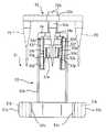
- FIG. 1Ais a front view showing a configuration of an operation unit of the suturing device according to the embodiment of the present invention.
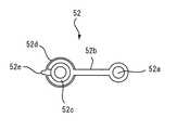
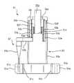
- FIG. 1Bis a front view showing a configuration of a suturing portion of the suturing device according to the embodiment of the present invention.
- FIG. 2Ais a front view of a rear arm constituting the stitching portion shown in FIG. 1B.
- 2Bis a plan view of the rear arm shown in FIG. 2A.
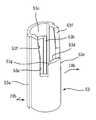
- FIG. 3Ais a front view of the front arm that constitutes the suture portion shown in FIG. 1B.
- 3Bis a plan view of the front arm shown in FIG. 3A.
- 3Cis a plan view of the front arm shown in FIG. 3B with the cap removed.
- FIG. 3Ais a front view showing a configuration of an operation unit of the suturing device according to the embodiment of the present invention.
- FIG. 1Bis a front view showing a configuration of a suturing portion of the suturing device according
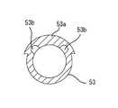
- FIG. 4Ais a perspective view of a front guide portion constituting the front arm shown in FIG. 3A.
- 4Bis a cross-sectional view taken along line IVb-IVb in FIG. 4A.
- FIG. 5Ais a front view for explaining the operation of the rear arm with respect to the front arm, and shows a state in which the rear arm is separated from the front arm.
- FIG. 5Bis a plan view of FIG. 5A.
- FIG. 6Ais a front view for explaining the operation of the rear arm with respect to the front arm, and shows a state where the needle-like member is positioned on one thread support portion and the rear arm is brought close to the front arm. It is. 6B is a plan view of FIG. 6A.
- FIG. 6Ais a front view for explaining the operation of the rear arm with respect to the front arm, and shows a state where the needle-like member is positioned on one thread support portion and the rear arm is brought close to the front arm. It is. 6B is a plan view of
- FIG. 7Ais a front view for explaining the operation of the rear arm with respect to the front arm, and shows a state where the needle-like member is positioned on the other thread support portion and the rear arm is brought close to the front arm. It is.
- FIG. 7Bis a plan view of FIG. 7A.
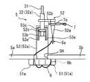
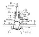
- FIG. 8Ais a view showing a procedure of a procedure (suture) performed using the suturing device according to the embodiment of the present invention, and is a view showing a first step.
- FIG. 8Bis a diagram showing a second step subsequent to FIG. 8A.
- FIG. 8Cis a diagram showing a third step subsequent to FIG. 8B.
- FIG. 8Dis a diagram showing a fourth step that follows FIG. 8C.
- FIG. 8Eis a diagram showing a fifth step subsequent to FIG. 8D.
- FIG. 8Fis a diagram showing a sixth step subsequent to FIG. 8E.
- FIG. 8Gis a diagram showing a seventh step that follows FIG. 8F.
- FIG. 8His a diagram showing an eighth step that follows FIG. 8G.
- FIG. 8Iis a diagram showing a ninth step that follows FIG. 8H.
- FIG. 8Jis a diagram showing a tenth process continued from FIG. 8I.
- FIG. 8Kis a diagram showing a final step subsequent to FIG. 8J.
- a suturing device 1is a device that is inserted into a body while being attached to an endoscope (soft endoscope or the like) 2.
- Thisis a device for suturing an incision or the like formed in an organ in the abdominal cavity or the digestive tract by an operation outside the body while being visually recognized by a camera (not shown).
- the suturing device 1is provided at a sheath portion 3 disposed along the shaft of the endoscope 2, an operation portion (handle) 4 provided at the proximal end of the sheath portion 3, and a distal end of the sheath portion 3.
- the sewing part 5is generally provided.
- the sheath part 3is a long member extending along the axial direction, and has two tubes and one wire (or one having flexibility enough to follow the bending of the shaft of the endoscope 2). 3 tubes). That is, the sheath portion 3 is configured to include a front arm moving wire 31, a rear arm moving tube 32, and a case tube 33.
- the front arm moving wire 31is made of a flexible wire, is slidably inserted into the rear arm moving tube 32, and can move along the axial direction in the rear arm moving tube 32. It is provided so that it can rotate around.
- a wire ropeis used in this embodiment.
- the wire ropeis a rope made of a stranded wire formed by twisting a plurality of wires (cables) made of, for example, metal (stainless steel) or the like.
- the wire 31may be a single wire. Further, a hollow tube may be used instead of the wire 31.
- the rear arm moving tube 32is formed of a hollow tube that is slidably inserted into the case tube 33, and is provided in the case tube 33 so as to be movable along the axial direction and rotatable about the axis.
- the rear arm moving tube 32has flexibility and may be a tube made of resin or the like, but in this embodiment, a coil tube having excellent durability is used.
- As the coil tubea flat wire coil tube formed by spirally winding a long flat plate made of metal (stainless steel) or the like can be used. However, a round wire coil tube or an inner flat coil tube may be used.
- a wire tubemay be used as the rear arm moving tube 32.
- the wire tubeis a tube formed by spirally twisting a plurality of wires (cables) made of, for example, metal (stainless steel) or the like so as to be hollow.
- the rear arm moving tube 32may be a uniform member (for example, a coil tube) from the proximal end to the distal end, but in this embodiment, the distal end of the coil tube is substantially made of a rigid metal.
- a cylindrical memberis fixed by welding to form a distal end portion (tube distal end portion) 32a of the rear arm moving tube 32.
- the case tube 33is a flexible hollow tube made of resin or the like.
- the proximal ends of the front arm moving wire 31 and the rear arm moving tube 32are connected to the operation unit 4, and the distal ends of the front arm moving wire 31 and the rear arm moving tube 32 are connected to the suture unit 5. Yes.
- the proximal end of the case tube 33reaches the vicinity of the operation unit 4, but is not connected to the operation unit 4, and the distal end of the case tube 33 reaches the vicinity of the suture unit 5, It is not connected to the stitched portion 5.
- the case tube 33can be formed of a material such as polyethylene or vinyl chloride, for example.
- a substantially cylindrical fixing member 33ais integrally attached to the distal end of the case tube 33.
- the distal end portion of the shaft of the endoscope 2is press-fitted into the fixing member 33a, whereby the suturing device 1 is fixed. It can be detachably fixed to the endoscope 2.
- the entire operation unit 4By moving (sliding) the entire operation unit 4 to the distal end side or the proximal end side with respect to the case tube 33, the entire suture unit 5 is moved with respect to the endoscope 2, and the operation unit 4 is moved. Is rotated about its axis with respect to the case tube 33, so that the entire suture portion 5 can be rotated.
- the suturing portion 5 of the suturing device 1is configured as shown in FIG. 1B. That is, the suture part 5 includes a front arm 51 to which the suture thread 6 is attached and a rear arm 52 having a needle-like member 52a.
- the rear arm 52includes a needle-like member 52a, a needle support portion 52b, a rear guide portion 52c, and a protruding member 52d.
- the rear guide portion 52cis made of a substantially cylindrical member, one end of a substantially strip-shaped needle support portion 52b is fixed to the upper end side of the rear guide portion 52c, and the rear guide portion 52c protrudes from the lower end side of the rear guide portion 52c.
- the member 52dis fixed.
- the proximal end portion of the needle-like member 52ais fixed to the other end of the needle support portion 52b so as to be directed forward (distal end side).
- the protruding member 52dhas a protruding portion 52e.
- the needle-like member 52a, the needle support portion 52b, the rear guide portion 52c, and the protruding member 52dare not particularly limited. Are fixed integrally with each other.
- the protrusion part 52eis not specifically limited, in this embodiment, it is arrange
- the rear end surface (the end surface on the proximal end side) of the rear guide portion 52cis integrally fixed to the distal end portion 32a of the rear arm moving tube 32 by laser welding or the like (see FIG. 1B). ).
- the rear guide portion 52cis inserted into the front guide portion 53, which will be described later, from the end on the protruding member 52d side, and is held so as to be slidable along the axial direction and rotatable about the axis. ing.
- the needle-like member 52ahas a straight barrel-shaped large diameter portion 52a1, a tapered tapered portion 52a2, a straight barrel-shaped small-diameter portion 52a3, and a sharp portion with a sharp tip formed from the proximal end side toward the distal end side. 52a4.
- the flange portion 52a4is formed such that the outer diameter of the base end thereof is larger than the outer diameter of the distal end of the small diameter portion 52a3, and a step is slightly formed at the connecting portion with the small diameter portion 52a3.
- the needle-like member 52ais fixed to the needle support portion 52b so that the tip thereof faces the front arm 51 and the central axis thereof is substantially parallel to the central axis of the rear guide portion 52c. In addition, it is the direction of the central axis of the needle-shaped member 52a, Comprising: The direction toward a front-end
- the needle-like member 52ais moved to the tip 32a while the central axis of the needle-like member 52a is maintained substantially parallel to the central axis of the tip 32a. It can be rotated (turned) around the central axis.
- the needle-like member 52acan be inserted into the object to be sutured (internal wall) to penetrate the object, and the needle-like member 52a can be pulled out from the object by moving in the reverse direction from the state of penetration.
- the material, the length, and the shaft diameterare not particularly limited.
- the lengthmay be a length that can penetrate the stomach wall, and the material is preferably made of metal in terms of strength.
- the length of the needle-like member 52ais preferably about 7 to 20 mm, and more preferably about 7 to 10 mm.
- the shaft diameter of the large diameter portion 52a1 of the needle-like member 52ais about 1.5 to 3.0 mm
- the shaft diameter of the small diameter portion 52a3is about 0.5 to 1 mm
- the shaft diameter of the twisting portion 52a4is 0. About 6 to 1.5 mm is preferable.
- a ligation tool 7 for ligating the suture thread 6is attached to the proximal end portion (large diameter portion 52a1) of the needle-like member 52a.
- the ligation tool 7is integrally provided with a ligation loop 7c through which the suture thread 6 is passed at one end in the axial direction of a connection portion formed in a substantially cylindrical shape, and a linking loop 7b to which the ligation device is coupled at the other end.
- the tube 7ais slid toward the ligation loop 7c, whereby the ligation loop 7c is drawn into the lumen.
- a polyamide resinis used as the material of the main body, and a silicone elastomer is used as the material of the fastening tube 7a.
- both ends of a flexible wireare joined to form a loop member by forming a substantially loop shape (endless shape), and close to each other so that an intermediate portion of the loop member is substantially parallel.
- the intermediate portionmay be formed by slidably fitting a substantially cylindrical tube (clamping tube) 7a made of an elastic material.
- the front arm 51is generally configured to include a pair of thread support portions 51a, 51a, a front guide portion 53, and a cap.
- the pair of thread support portions 51a and 51ais formed in a substantially V shape (which may be an arc shape, a U shape, a U shape, etc.) and has a bifurcated shape.
- the suture thread 6is attached so as to extend between the vicinity of the respective distal end portions.
- Engaging members 6a and 6b formed in an annular shapeare attached to both ends of the suture thread 6 (see FIG. 1B).
- Through holes 51b and 51b penetrating over the front surface (distal end side surface) and the rear surface (proximal end side surface)are formed at the tip ends of the thread support portions 51a and 51a of the front arm 51, respectively.
- An accommodation space (not shown) in which the engaging members 6a and 6b can be engagedis formed on the rear surface side of the through holes 51b and 51b.
- Through grooves 51c and 51care formed in part of the side portions of the through holes 51b and 51b so as to allow the suture thread 6 to pass therethrough.
- the accommodation spacehas a slightly larger diameter than the through holes 51b and 51b, and the through holes through which the engaging members 6a and 6b penetrate the front and back surfaces of the accommodation spaces with respect to the through holes 51b and 51b of the yarn support portions 51a and 51a. It is set to a diameter that can be engaged and disengaged by the inner wall in a state of being arranged so as to be substantially concentric.
- the through-holes of the engaging members 6a and 6bcan be inserted through the threaded portion 52a4 of the needle-shaped member 52a.
- the needle-shaped member 52aextends from the engaging member 6a, 6b has a structure that does not fall out.
- the inner diameters of the engaging members 6a and 6bare smaller than the outer diameter of the handle portion 52a4 of the needle-like member 52a, but the tip of the small-diameter portion 52a3 of the needle-like member 52a (that is, with the handle portion 52a4). It is formed to be larger than the shaft diameter of the connecting portion).
- a suture accommodating portion(not shown) is provided at the center of the thread support portions 51a and 51a, and an intermediate portion of the suture thread 6 arranged over the thread support portions 51a and 51a is the suture thread. It is accommodated in the accommodating part.
- the front arm 51has a needle accommodation hole for protecting the needle-like member 52a (the edge portion 52a4) when the suturing device 1 is inserted into the body. It may be.
- the needle accommodation holemay be provided in one of the thread support parts 51a and 51a, or separately from the thread support parts 51a and 51a (for example, in a portion between one thread support part and the other thread support part). )
- a protrusionmay be provided and provided on the protrusion.
- a through hole 51d penetrating in the vertical directionis formed in the joint portion of each of the yarn support portions 51a and 51a of the front arm 51, and a substantially cylindrical guide shaft 51e is formed in the through hole 51d. It is fixed so as to protrude toward the rear side.
- the guide shaft 51eis a member that is slidably inserted into the lumen of the rear guide portion 52c and guides the reciprocating movement and rotation of the rear arm 52 in the central axis direction.
- the guide shaft 51eis made of metal such as stainless steel, and the distal end of the front arm moving wire 31 is formed by laser welding or the like at the rear end (end on the proximal end side) of the guide shaft 51e. It is fixed integrally.
- the front guide portion 53is formed of a substantially cylindrical member, and a part of the thickness on the back side is formed thicker than that on the front side. It has become.
- a pair of concave guide groovesextend in the vertical direction (a direction substantially parallel to the central axis) on the inner surface side of the thick portion 53a and are recessed in the radial direction. Grooves) 53b and 53b are formed.
- the concave guide grooves 53b, 53bare slidably fitted into one of the protrusions 52d formed on the protrusion member 52d of the rear arm 52 so as to be slidable in the direction of the central axis of the rear arm 52. It is a part which guides the slide.
- connection groove 53 cthat is recessed in an arc shape is formed in the upper part of the inner wall of the front guide part 53.
- the connection groove 53cslides the rear guide portion 52c toward the proximal end side with respect to the front guide portion 52, and the projection 52e is located at the position of the connection groove 53c (that is, the concave guide groove 53b).
- 53bin a state of being pulled out), the portion for allowing the rear guide portion 52c (rear arm 52) to turn (turn).
- connection groove 53cBoth ends (surfaces) of the connection groove 53c are continuous with the outer portions of the inner walls of the concave guide grooves 53b and 53b, respectively, and the depth is the same as the depth of the concave guide grooves 53b and 53b.
- the concave guide grooves 53b and 53breach the lower portion (front end) of the front guide portion 53.
- a notchis formed in the upper part on the front side of the front guide part 53.
- a penetration guideis formed extending in the vertical direction (direction substantially parallel to the central axis) and penetrating inward and outward.
- Grooves (first guide groove, second guide groove) 53e, 53eare formed.
- the through guide grooves 53e and 53eare portions in which the needle support portion 52b of the rear arm 52 is slidably fitted in either of them to guide the slide in the central axis direction of the rear arm 52. It is.
- the side portions on both sides of the through guide grooves 53e and 53eare substantially parallel to the central axis direction and are substantially parallel to each other.
- These penetrating guide grooves 53e, 53ehave upper ends (rear ends) reaching the bottom 53d of the notch, and lower ends (front ends) not reaching the lower portion (front end) of the front guide portion 53.
- the positions of the lower ends (front ends) of the penetration guide grooves 53e and 53eare such that when the needle support portion 52b of the front arm 51 is fitted and reaches the lower end, the rear end of the needle portion 52a4 of the needle-like member 52a is It is set at a position where it can penetrate through the engaging member 6a or 6b of the suture thread 6 and engage.
- the penetration guide grooves 53e and 53eare formed so as to have substantially the same surface as one of the side portions on both sides (the sides on the outside).
- the connecting portion between the other side (the side on the inner side) of both sides of the penetration guide grooves 53e and 53e and the bottom side 53dthe needle support portion 52b is smoothly guided into the penetration guide grooves 53e and 53e.
- the chamfered portions 53g and 53gare chamfered in an arc shape.
- the connecting portionis not limited to an arc shape, and may be an inclined surface provided that the needle support portion 52b is smoothly guided into the through guide grooves 53e and 53e.
- a cap 54is attached to the rear end of the front guide portion 53.
- the cap 54has an arcuate recess 54a in which the rear guide portion 52c is disposed.
- FIGS. 5A, 5B, 6A, 6B, 7A, and 7BFirst, as shown in FIGS. 5A and 5B, when the rear arm 52 is slid away from the front arm 51, the protruding member 52d (protruding portion 52e) of the rear arm 52 moves. It is located in the connection groove 53 c of the front guide portion 53. In this state, the rear arm 52 can freely rotate with respect to the front arm 51 within a predetermined angle range (approximately 90 ° in the present embodiment) defined by both end faces of the connection groove 53c around the central axis. It can move (turn).
- a predetermined angle rangeapproximately 90 ° in the present embodiment
- the rotation of the rear arm 52 with respect to the front arm 51is limited, and the rear arm 52 is guided in the central axis direction along the concave guide groove 53b.
- the needle support portion 52bis guided to the penetration guide groove 53e and is fitted (freely fitted) into the penetration guide groove 53e.
- the fitting between the needle support portion 52b and the penetration guide groove 53eis such that there is no hindrance to the slide so that the tip of the handle portion 52a4 of the needle-like member 52a is accurately guided to the through hole 51b of the one thread support portion 51a.
- the conditionis set to be relatively tight. That is, the clearance is set to be relatively small.
- the needle support portion 52bWhen the rear arm 52 is slid so as to be closer to the front arm 51, the needle support portion 52b is guided by the penetration guide groove 53e, and the tip of the twisting portion 52a4 of the needle-like member 52a is one thread support portion.
- the needle support portion 52bis guided to the through hole 51b of 51a and stops in contact with the front end of the through guide groove 53e. Accordingly, as shown in FIGS. 6A and 6B, the suture thread 6 in which the tip of the handle portion 52a4 of the needle-like member 52a is supported by the through hole 51b in the through hole 51b of the one thread support portion 51a. It is located in the predetermined position which can be appropriately engaged with one engagement member 6a (refer FIG. 1B).
- the rotation of the rear arm 52 with respect to the front arm 51is limited, and the rear arm 52 is guided in the central axis direction along the concave guide groove 53b.
- the needle support portion 52bis guided to the penetration guide groove 53e and is fitted (freely fitted) into the penetration guide groove 53e.
- the fitting between the needle support portion 52b and the penetration guide groove 53eis such that there is no hindrance to the slide so that the tip of the handle portion 52a4 of the needle-like member 52a is accurately guided to the through hole 51b of the other thread support portion 51a.
- the conditionis set to be relatively tight. That is, the clearance is set to be relatively small.
- the needle support portion 52bWhen the rear arm 52 is slid so as to be closer to the front arm 51, the needle support portion 52b is guided by the penetration guide groove 53e, and the tip of the twist portion 52a4 of the needle-like member 52a is the other thread support portion.
- the needle support portion 52bis guided to the through hole 51b of 51a and stops in contact with the front end of the through guide groove 53e.
- FIGS. 7A and 7Bthe suture thread 6 is supported by the through hole 51b in the through hole 51b in the through hole 51b of the other thread support portion 51a.
- the other engaging member 6b(see FIG. 1B) is positioned at a predetermined position where it can be properly engaged.
- the protrusion 52eis guided by the concave guide groove 53b, Further, the needle support portion 52b is guided to the penetration guide groove 53e.
- the tip of the needle portion 52a4 of the needle-like member 52acan be properly engaged with the engaging members 6a and 6b of the suture thread 6 supported by the through hole 51b in the through hole 51b of the thread support portion 51a. Guided accurately to position. Therefore, when the rear arm 52 is brought close to the front arm 51, it is effectively prevented that the position of the rear arm 52 in the rotation direction with respect to the front arm 51 is shifted. For this reason, unlike the prior art, there is no need to perform alignment again, and the suturing treatment can be performed quickly.
- the relatively rough guide structure formed by the concave guide grooves 53b and 53b and the protrusion 52e and the relatively precise guide structure formed by the through guide grooves 53e and 53e and the needle support portion 52bare combined. Smooth guidance can be performed. With only a relatively precise guide structure using the penetration guide grooves 53e and 53e and the needle support portion 52b, the clearance between the penetration guide grooves 53e and 53e and the needle support portion 52b is small, so that the needle with respect to the penetration guide grooves 53e and 53e. The support 52b may not be smoothly introduced. However, such a problem can be solved by adding a relatively rough guide structure including the concave guide grooves 53b and 53b and the protrusion 52e as in the present embodiment, and smooth guidance as a whole can be realized.
- the relatively rough guide structure by the concave guide grooves 53b and 53b and the protrusion 52emay be omitted, and only a relatively precise guide structure by the through guide grooves 53e and 53e and the needle support part 52b may be used.
- the guide structure by the through guide grooves 53e and 53e and the needle support portion 52bmay be omitted, and only the guide structure by the concave guide grooves 53b and 53b and the protrusion 52e may be provided.
- the concave guide grooves 53b and 53bmay be provided.
- the protrusion 52emay be set to be relatively small. In the case of a single guide structure, the structure can be simplified although it may be slightly inferior from the viewpoint of smoothness of guide as compared to the combination of both.
- the operation unit (handle) 4 of the suturing device 1is configured as shown in FIG. 1A.
- the operation unit 4includes a slider unit 41 and a base unit 42.
- the slider part 41is slidably provided on the base part 42, and the slider part 41 moves to the base end (distal end) side and the base end (proximal end) side with respect to the base part 42. The two positions can be moved.
- the slider part 41is a cylindrical part 41a having a substantially cylindrical shape on the distal end side, and the distal end is fixed to the cylindrical part 41a on the proximal end side.
- a grip member 41bis provided.
- the cylindrical portion 41a of the slider portion 41is formed with a substantially cylindrical wire insertion hole (not shown) that opens at the distal end thereof and extends along the axial center thereof. The portion on the proximal end side is connected and fixed to the cylindrical portion 41 a of the slider portion 41.
- the base portion 42is formed of a substantially cylindrical member formed by joining a pair of substantially symmetric half members by a plurality of screws or the like (not shown), and opens at a proximal end thereof. It has a substantially cylindrical slider portion insertion hole (not shown) extending along. By inserting the cylindrical portion 41a of the slider portion 41 into the slider portion insertion hole, the slider portion 41 can be slid along the axis and can rotate about the axis with respect to the base portion. It is attached.
- the base portion 42has a substantially cylindrical tube insertion hole (not shown) that opens at the distal end thereof and extends along the axis thereof, and the rear arm moving tube is formed in the tube insertion hole.
- the proximal end side of the rear arm moving tube 32is connected and fixed to the base portion 42.
- the shaft of the endoscope 2 to which the suturing device 1 is attachedis inserted into the stomach, and the suturing portion 5 of the suturing device 1 is disposed in the vicinity of the incision portion to be sutured.
- the operation unit 4is operated so that the rear arm 52 is separated from the front arm 51 as shown in FIG. 1B.
- the operation unit 4is pushed into the distal end side as a whole with respect to the case tube 33 and rotated as necessary, as shown in FIG. Only the front arm 51 that is spaced apart from the rear arm 52 is inserted into the incision SH. Before and after this, the rear arm 52 is rotated with respect to the front arm 51, and one mouth of the incision portion SH is formed by one thread support portion 51 a of the front arm 51 and the needle-like member 52 a (the edge portion 52 a 4). The front arm 51 and the rear arm 52 are arranged so that the edge portion Sa is sandwiched.
- the needle-like member 52apierces one of the mouth edge portions Sa, penetrates the mouth edge portion Sa, Further, the tail portion 52a4 of the needle-like member 52a passes through the through hole of the engaging member 6a accommodated (supported) in the accommodation space of the one thread support portion 51a. Thereby, the through hole of the engagement member 6a reaches the small diameter portion 52a3 of the needle-like member 52a, and the engagement member 6a is engaged with the needle-like member 52a.
- the front arm 51is set such that the other mouth edge Sb of the incision SH is sandwiched between the other thread support 51 a and the needle-like member 52 a of the front arm 51. 51 and the rear arm 52 are arranged.
- the needle-like member 52apierces the other mouth edge Sb as shown in FIG. 8E.
- the penetrating portion 52a4 of the needle-like member 52apasses through the through-hole of the engaging member 6b accommodated (supported) in the accommodation space of the other thread support portion 51a. .
- the through-hole of the engaging member 6breaches the small diameter portion 52a3 of the needle-like member 52a, and the engaging member 6b is engaged with the needle-like member 52a.
- the pair of engaging members 6a and 6b, to which both ends of the suture thread 6 are fixed,are both engaged with the single needle-like member 52a, and the needle-like member 52a (that is, the stomach) is engaged by the suture thread 6.
- a ringis formed that penetrates the first perforation from the inner side to the outside of the stomach and returns from the outer surface of the stomach to the needle-like member 52a (that is, the stomach) through the second perforation.
- the operation unit 4is operated to move the front arm 51 (thread support unit 51a) into the stomach through the incision SH as shown in FIG. 8G.
- the needle-like member 52amoves away from the incision part SH, and both ends of the suture thread 6 move away from the incision part SH.
- the portion that penetrates the first perforation and the portion that penetrates the second perforationare drawn, and the end surfaces of the pair of mouth edge portions Sa and Sb of the incision SH are brought into contact with each other and joined.
- the ligation device 8includes, for example, a sheath introduced into a lumen via a treatment instrument guide tube of an endoscope, and an operation wire slidably inserted in the sheath, and the distal end of the operation wire At the end, a connecting hook that protrudes from the distal end of the sheath into a substantially V shape by its own elasticity and closes by being pulled into the distal end of the sheath is provided. Can be used.
- the ligature tool 7is held in a state where the ligation loop 7c (see FIG. 1B) is inserted into the proximal end portion (large diameter portion 52a1) of the needle-like member 52a.
- the distal end of the device 8(see FIG. 8H) is disposed in the vicinity of the connection loop 7b of the ligation device 7, and the connection loop 7b is grasped by a connection hook protruding from the ligation device 8 and opened, and the connection
- the ligation tool 7is connected to the distal end of the sheath of the ligating device 8 by drawing the loop 7 b into the distal end of the sheath of the ligating device 8.
- the distal end portion of the sheath of the ligating apparatus 8 to which the ligature tool 7 is connectedis moved to the incision SH side (downward in FIG. 8H) to Assume that both ends of the suture thread 6 are inserted inside the ligation loop 7c. As a result, the suture thread 6 is squeezed and both ends of the suture thread 6 are bundled.
- the position of the ligation wireis not changed, and if the sheath is slid toward the proximal end so as to draw the sheath with respect to the operation wire of the ligation device 8, The other end of the connecting hook and the loop member protrudes (exposes) from the distal end, the connecting hook is opened by its own elasticity, the grip is released, and as shown in FIG. The ligating device 8 is separated from the ligated tool 7 thus formed.
- the suture thread 6 between the ligature 7 and the suture part 5is cut with an endoscopic scissors forceps called a loop cutter. Then, the ligation tool 7 and the suture part 5 are separated, and if necessary, the other end of the loop member of the ligation tool 7 in a ligated state is cut and collected by a loop cutter or the like, so that one stitch is sewn. A series of procedures related to is completed.
- Penetration guide groove(first guide groove, second guide groove) 53f ... inclined portion 53g ... chamfered portion 54 ... cap 6 ... suture 6a, 6b ... engaging member 7 ... ligating tool 7a ... tightening tube 7b ... coupling loop 7c ... ligating loop SH ... incision portion Sa, Sb ... Mouth edge 8 ... Ligation device
Landscapes
- Health & Medical Sciences (AREA)
- Life Sciences & Earth Sciences (AREA)
- Surgery (AREA)
- Molecular Biology (AREA)
- General Health & Medical Sciences (AREA)
- Biomedical Technology (AREA)
- Heart & Thoracic Surgery (AREA)
- Medical Informatics (AREA)
- Nuclear Medicine, Radiotherapy & Molecular Imaging (AREA)
- Animal Behavior & Ethology (AREA)
- Engineering & Computer Science (AREA)
- Public Health (AREA)
- Veterinary Medicine (AREA)
- Physics & Mathematics (AREA)
- Biophysics (AREA)
- Optics & Photonics (AREA)
- Pathology (AREA)
- Radiology & Medical Imaging (AREA)
- Surgical Instruments (AREA)
Abstract
Description
Translated fromJapanese本発明は、経管腔的内視鏡手術において、消化管等の体内組織に形成された切開部等を縫合する縫合装置に関する。The present invention relates to a suturing device for suturing an incision formed in a body tissue such as a digestive tract in transluminal endoscopic surgery.
経管腔的内視鏡手術(NOTES:Natural Orifice Translumenal Endoscopic Surgery)は体表面に創を作らない低侵襲手術として近年注目を集めている。体表を切開し、体腔内の患部へ到達する従来の外科手術とは異なり、内視鏡を用いて口、肛門、尿道口、膣口等の自然孔から消化管、尿道、産道等を経由させて、患部へ処置具を到達させる。このような経管腔的内視鏡手術は、腹腔内観察、肝生検等の診断的手技から虫垂切除、胆嚢摘出、卵管結紮、卵巣摘出、胃小腸吻合など多様な手技への応用の可能性が報告されている。Transluminal endoscopic surgery (NOTES) has recently attracted attention as a minimally invasive surgery that does not create wounds on the body surface. Unlike conventional surgery, which cuts through the body surface and reaches the affected area in the body cavity, it passes through the gastrointestinal tract, urethra, birth canal, etc. through natural holes such as the mouth, anus, urethral opening, and vaginal opening using an endoscope. And let the treatment tool reach the affected area. Such transluminal endoscopic surgery is applied to various procedures such as appendectomy, cholecystectomy, fallopian tube ligation, ovariectomy, and gastrointestinal anastomosis from diagnostic procedures such as intraperitoneal observation and liver biopsy. The possibility has been reported.
経管腔的内視鏡手術において、消化管等の体内組織に形成された切開部(穿孔部や欠損部等を含む)を縫合する縫合装置としては、下記特許文献1に記載のものが提案されている。この縫合装置は、縫合糸が掛け渡すように装着される二股状の先端部を有する前側アームと、穿刺用の針を有する後側アームと、これらを相対的に回動および移動させる機構を備えている。As a suturing device for suturing an incision part (including a perforation part and a defect part) formed in a body tissue such as a digestive tract in transluminal endoscopic surgery, the one described in
ところで、このような縫合装置を用いて縫合を行う際には、針が前側アームの二股状の先端部(縫合糸の両端を支持している部分)にそれぞれ精度よく一致するように、前側アームに対して後側アームの回動方向の位置を設定し、その後に前側アームに対して後側アームを近接するように移動させる必要がある。しかしながら、従来技術では、前側アームに対して後側アームを近接させる際に、前側アームに対する後側アームの回動方向の位置がずれてしまう場合がある。このため、再度の位置合わせを行う必要がある等、迅速な処置の障害となる場合があり、その改善が求められている。By the way, when performing suturing using such a suturing device, the front arm is adjusted so that the needle accurately matches the bifurcated tip of the front arm (the portion supporting both ends of the suture). It is necessary to set the position of the rear arm in the rotational direction with respect to the rear arm and then move the rear arm closer to the front arm. However, in the related art, when the rear arm is brought close to the front arm, the position of the rear arm in the rotational direction may be shifted with respect to the front arm. For this reason, there is a case where it becomes an obstacle to a quick treatment, such as the necessity of performing alignment again, and the improvement is demanded.
本発明は、このような実状に鑑みてなされ、その目的は、体内組織の縫合を短時間で行い得る縫合装置を提供することである。The present invention has been made in view of such a situation, and an object thereof is to provide a suturing apparatus capable of suturing a body tissue in a short time.
上記目的を達成するために、本発明に係る縫合装置は、
体内に挿入されて使用される縫合装置であって、
縫合糸の両端を支持する糸支持部および該糸支持部に取り付けられた前側ガイド部を有する前側アームと、
針状部材、該針状部材を所定の第1方向を指向した状態で支持する針支持部、および前記前側ガイド部に該第1方向に実質的に平行する方向にスライド可能にかつ該第1方向に実質的に平行する軸周りに回動可能に取り付けられた後側ガイド部を有する後側アームと、を備え、
前記前側ガイド部は、前記後側アームを前記第1方向にスライドさせた場合に、前記針状部材を前記糸支持部に支持された前記縫合糸の一端に向けて案内する第1ガイド溝および該縫合糸の他端に向けて案内する第2ガイド溝を有する。In order to achieve the above object, a suturing device according to the present invention comprises:
A suturing device that is inserted into the body and used.
A front arm having a thread support part for supporting both ends of the suture and a front guide part attached to the thread support part;
A needle-like member, a needle support portion that supports the needle-like member in a state oriented in a predetermined first direction, and the first guide portion slidable in a direction substantially parallel to the first direction. A rear arm having a rear guide portion pivotably mounted about an axis substantially parallel to the direction,
The front guide portion includes a first guide groove that guides the needle-like member toward one end of the suture supported by the yarn support portion when the rear arm is slid in the first direction. A second guide groove is provided for guiding toward the other end of the suture thread.
本発明では、後側アームを第1方向(後側アームが前側アームに近接する方向)にスライドさせると、第1ガイド溝によって針状部材は糸支持部に支持された縫合糸の一端に向けて案内され、第2ガイド溝によって針状部材は糸支持部に支持された縫合糸の他端に向けて案内される。したがって、前側アームに対して後側アームを近接させる際に、前側アームに対する後側アームの回動方向の位置がずれてしまうことが防止される。このため、従来技術のように、再度位置合わせを行わなければならないという場合がなくなり、縫合処置を迅速に行うことができるようになる。In the present invention, when the rear arm is slid in the first direction (the direction in which the rear arm is close to the front arm), the needle-shaped member is directed toward one end of the suture supported by the thread support portion by the first guide groove. The needle-shaped member is guided toward the other end of the suture supported by the thread support portion by the second guide groove. Therefore, when the rear arm is brought close to the front arm, the position of the rear arm in the rotation direction with respect to the front arm is prevented from being shifted. For this reason, unlike the prior art, there is no need to perform alignment again, and the suturing treatment can be performed quickly.
本発明において、前記前側ガイド部を略円筒状の部材とし、前記第1ガイド溝および前記第2ガイド溝を、前記第1方向に実質的に平行する方向に延在するとともに、前記前側ガイド部の壁部に内外に渡って形成された貫通ガイド溝とし、前記後側ガイド部を前記前側ガイド部の内側に配置し、前記貫通ガイド溝に前記針支持部をスライド可能に遊嵌させて構成することができる。このように構成することにより、簡単な構成で、針状部材を縫合糸の両端のそれぞれに正確に位置合わせし得る。In the present invention, the front guide portion is a substantially cylindrical member, and the first guide groove and the second guide groove extend in a direction substantially parallel to the first direction, and the front guide portion A through guide groove formed in the wall portion of the inner side and the outer side, the rear guide portion being arranged inside the front guide portion, and the needle support portion being slidably fitted in the through guide groove. can do. With this configuration, the needle-like member can be accurately aligned with both ends of the suture with a simple configuration.
また、本発明において、前記前側ガイド部を略円筒状の部材とし、前記第1ガイド溝および前記第2ガイド溝を、前記第1方向に実質的に平行する方向に延在するとともに、前記前側ガイド部の内壁に形成された凹状ガイド溝とし、前記後側ガイド部を前記前側ガイド部の内側に配置し、前記後側ガイド部に、前記凹状ガイド溝に遊嵌される突起部を設けて構成することができる。このように構成することにより、簡単な構成で、針状部材を縫合糸の両端のそれぞれに正確に位置合わせし得る。In the present invention, the front guide portion is a substantially cylindrical member, and the first guide groove and the second guide groove extend in a direction substantially parallel to the first direction, and the front side A concave guide groove formed on the inner wall of the guide portion, the rear guide portion is disposed inside the front guide portion, and a projection portion that is loosely fitted in the concave guide groove is provided on the rear guide portion. Can be configured. With this configuration, the needle-like member can be accurately aligned with both ends of the suture with a simple configuration.
本発明において、体内組織を縫合した前記縫合糸を結紮するために用いられる結紮具が前記針状部材に装着してあるようにすることができる。In the present invention, a ligation tool used for ligating the suture thread obtained by suturing a body tissue can be attached to the needle-like member.
以下、本発明の実施形態について、図面を参照して詳細に説明する。Hereinafter, embodiments of the present invention will be described in detail with reference to the drawings.
(縫合装置の全体構成)
図1Aおよび図1Bに示すように、本実施形態に係る縫合装置1は、内視鏡(軟性内視鏡等)2に取り付けられた状態で体内に挿入される装置であり、内視鏡2の不図示のカメラによって視認しながら、腹腔内の臓器や消化管に形成された切開部等を体外における操作により縫合するための装置である。(Overall configuration of suturing device)
As shown in FIGS. 1A and 1B, a
縫合装置1は、内視鏡2のシャフトに沿って配置されるシース部3、シース部3の近位端に設けられた操作部(ハンドル)4、およびシース部3の遠位端に設けられた縫合部5を概略備えて構成されている。The
(シース部)
シース部3は、軸方向に沿って延びた長尺な部材であり、内視鏡2のシャフトの屈曲に追従して屈曲できる程度の柔軟性を有する2本のチューブと1本のワイヤ(または3本のチューブ)から構成されている。すなわち、シース部3は、前側アーム移動ワイヤ31、後側アーム移動チューブ32、およびケースチューブ33を概略備えて構成されている。(Sheath part)
The
前側アーム移動ワイヤ31は、可撓性を有する線材からなり、後側アーム移動チューブ32にスライド可能に挿通されて、該後側アーム移動チューブ32内において、その軸方向に沿って移動可能かつ軸周りに回転できるように設けられている。前側アーム移動ワイは31としては、本実施形態ではワイヤロープを用いている。ワイヤロープは、たとえば金属(ステンレス)等からなる複数本のワイヤ(ケーブル)を螺旋状に撚ってなる撚り線からなるロープである。ただし、ワイヤ31としては、単線からなるワイヤを用いてもよい。また、ワイヤ31に代えて、中空チューブを用いてもよい。The front
後側アーム移動チューブ32は、ケースチューブ33にスライド可能に挿通された中空チューブからなり、ケースチューブ33内において、その軸方向に沿って移動可能かつ軸周りに回転できるように設けられている。後側アーム移動チューブ32としては、可撓性を有しており、樹脂等からなるチューブを用いてもよいが、本実施形態では、耐久性に優れるコイルチューブを用いている。コイルチューブとしては、金属(ステンレス)等からなる長尺平板を螺旋状に巻回してなる平線コイルチューブを用いることができる。ただし、丸線コイルチューブまたは内面平コイルチューブを用いてもよい。The rear
なお、後側アーム移動チューブ32としては、ワイヤチューブを用いてもよい。ワイヤチューブは、たとえば金属(ステンレス)等からなる複数本のワイヤ(ケーブル)を中空となるように螺旋状に撚ってなるチューブである。Note that a wire tube may be used as the rear
後側アーム移動チューブ32は、その近位端から遠位端まで一様な部材(たとえばコイルチューブ)としてもよいが、本実施形態では、コイルチューブの遠位端に剛性の高い金属からなる略円筒状の部材を溶接固定して、後側アーム移動チューブ32の先端部(チューブ先端部)32aとしている。The rear
ケースチューブ33は、樹脂等からなる可撓性を有する中空チューブである。前側アーム移動ワイヤ31および後側アーム移動チューブ32の近位端は操作部4に接続されており、前側アーム移動ワイヤ31および後側アーム移動チューブ32の遠位端は縫合部5に接続されている。ケースチューブ33の近位端は、操作部4の近傍にまで至っているが、操作部4には接続されておらず、ケースチューブ33の遠位端は、縫合部5の近傍まで至っているが、縫合部5には接続されていない。ケースチューブ33は、たとえば、ポリエチレンや塩化ビニル等の素材で形成することができる。The
ケースチューブ33の遠位端には、略円筒状の固定部材33aが一体的に取り付けられており、固定部材33aに内視鏡2のシャフトの先端部が圧入されることにより、縫合装置1を内視鏡2に対して、着脱可能に固定できるようになっている。操作部4の全体をケースチューブ33に対して遠位端側または近位端側に移動(スライド)させることにより、内視鏡2に対して、縫合部5の全体を移動させ、操作部4の全体をケースチューブ33に対してその軸周りに回転させることにより、縫合部5の全体を回転させることができる。A substantially cylindrical fixing
(縫合部)
縫合装置1の縫合部5は、図1Bに示すように構成されている。すなわち、縫合部5は、縫合糸6が装着される前側アーム51と、針状部材52aを有する後側アーム52とを備えて構成されている。(Suture)
The
後側アーム52は、図2Aおよび図2Bに示されているように、針状部材52a、針支持部52b、後側ガイド部52c、および突起部材52dを有している。後側ガイド部52cは略円筒状の部材からなり、後側ガイド部52cの上端側に略短冊板状の針支持部52bの一端が固定されており、後側ガイド部52cの下端側に突起部材52dが固定されている。2A and 2B, the
針支持部52bの他端には、前方(遠位端側)を指向して、針状部材52aの基端部が固定されている。突起部材52dは、突起部52eを有している。これらの針状部材52a、針支持部52b、後側ガイド部52cおよび突起部材52dは、特に限定されないが、たとえば、ステンレス等の金属からなり、それぞれ別々の部品として形成された後に、レーザ溶接等により互いに一体的に固定されている。なお、突起部52eは、特に限定されないが、本実施形態では、針支持部52bの延在方向に対して180°反対側に突出するように配置されている。The proximal end portion of the needle-
後側アーム52は、後側ガイド部52cの後端面(近位端側の端面)が後側アーム移動チューブ32の先端部32aに、レーザ溶接等により一体的に固定されている(図1B参照)。後側ガイド部52cは、突起部材52d側の端部から、後述する前側ガイド部53の内側に挿入され、その軸方向に沿ってスライド可能かつ軸周りに回動可能に保持されるようになっている。In the
針状部材52aは、その基端側から先端側に向かって、直胴状の大径部52a1、先細のテーパ部52a2、直胴状の小径部52a3、および先端が鋭利に形成されたやじり部52a4を有している。やじり部52a4は、その基端の外径が小径部52a3の先端の外径よりも大きく、小径部52a3との連結部分に僅かに段差ができるように形成されている。針状部材52aは、その先端が前側アーム51に向いた状態かつ、その中心軸が後側ガイド部52cの中心軸と略平行となるように針支持部52bに固定されている。なお、針状部材52aの中心軸の方向であって、基端から先端に向かう方向が第1方向である。The needle-
後側アーム移動チューブ32をその中心軸周りに回転させれば、針状部材52aの中心軸が先端部32aの中心軸と略平行な状態を維持したまま、針状部材52aを先端部32aの中心軸周りに回動(旋回)させることができる。If the rear
なお、針状部材52aは、縫合する対象(体内壁)に突き刺してその対象を貫通させることができ、しかも、対象を貫通した状態から逆方向に移動させて対象から引き抜くことができる程度の長さおよび強度を有するものであればよく、その素材や長さ、軸径は特に限定されない。たとえば、縫合装置1によって胃壁を縫合する場合であれば、その長さは、胃壁を貫通できる程度の長さであればよく、その素材は金属製が強度の点で好ましい。たとえば、針状部材52aの長さは、7~20mm程度が好ましく、7~10mm程度がより好ましい。また、針状部材52aの大径部52a1の軸径は1.5~3.0mm程度、小径部52a3の軸径は0.5~1mm程度、やじり部52a4の軸径は最大径で0.6~1.5mm程度が好ましい。In addition, the needle-
針状部材52aの基端部(大径部52a1)には、図1Bに示すように、縫合糸6を結紮するための結紮具7が装着される。結紮具7は、略円柱状に形成された接続部の軸方向の一端に縫合糸6が通される結紮用ループ7cを一体的に設け、他端に結紮装置が連結される連結用ループ7bを一体的に設けてなる本体部と、該接続部に、弾性を有する素材からなる略円筒状のチューブ(締付チューブ)7aを、スライド可能に外嵌して構成されている。結紮時には、チューブ7aを結紮用ループ7c側にスライドさせることにより、該結紮用ループ7cがその内腔に引き込まれる。本体部の素材としては、たとえばポリアミド樹脂が用いられ、締付チューブ7aの素材としては、たとえばシリコーンエラストマーが用いられる。As shown in FIG. 1B, a
なお、特に限定されないが、本実施形態では、結紮用ループ7cをチューブ7a内に引き込み過ぎてしまい、結紮用ループ7cがチューブ7aから抜け出してしまうことを防止するため、該結紮用ループ7cの一部を係止する係止部材7dを設けている。また、結紮具7としては、可撓性を有する線材の両端を結合して略ループ状(無端状)に成形してループ部材とするとともに、ループ部材の中間部分を略平行するように互いに近接させて、該中間部分に、弾性を有する素材からなる略円筒状のチューブ(締付チューブ)7aをスライド可能に外嵌して構成されたものを用いてもよい。Although not particularly limited, in the present embodiment, in order to prevent the
前側アーム51は、図1B、図3A~図3Cに示すように、一対の糸支持部51a,51a、前側ガイド部53およびキャップ54を概略備えて構成されている。一対の糸支持部51a,51aは、略V状(円弧状、コの字状、U字状等であってもよい)に形成されて二股状になっており、糸支持部51a,51aのそれぞれの先端部近傍間に渡るように、縫合糸6が装着される。縫合糸6の両端には、それぞれ円環状に形成された係合部材6a,6bが取り付けられている(図1B参照)。As shown in FIG. 1B and FIGS. 3A to 3C, the
前側アーム51の糸支持部51a,51aのそれぞれの先端部には、前面(遠位端側の面)および後面(近位端側の面)に渡って貫通する貫通孔51b,51bが形成されており、該貫通孔51b,51bの後面側に係合部材6a,6bが係合可能な収容空間(不図示)が形成されている。貫通孔51b,51bの側部の一部には、縫合糸6が通過し得るように、内外に渡り貫通溝51c,51cが形成されている。収容空間は、該貫通孔51b,51bよりも僅かに大きい径であって、係合部材6a,6bがその表裏を貫通する貫通孔が糸支持部51a,51aの貫通孔51b,51bに対して略同心となるように配置した状態で、その内壁によって係脱可能に係合され得る程度の径に設定されている。Through
各係合部材6a,6bの貫通孔は、針状部材52aのやじり部52a4を挿通させることはできるが、やじり部52a4が完全に該貫通孔を挿通すると針状部材52aから係合部材6a,6bが抜け落ちない構造となっている。具体的には、各係合部材6a,6bは、その内径が針状部材52aのやじり部52a4の外径よりも小さいが、針状部材52aの小径部52a3の先端(つまりやじり部52a4との連結部分)の軸径よりも大きくなるように形成されている。なお、糸支持部51a,51aの中央部には縫合糸収容部(不図示)が設けられており、糸支持部51a,51aに渡って配置された縫合糸6の中間部分は、この縫合糸収容部に収容されるようになっている。The through-holes of the engaging
なお、本実施形態では設けていないが、前側アーム51には、この縫合装置1の体内への挿入時等に、針状部材52a(やじり部52a4)を保護するための針収容穴を有していてもよい。針収容穴としては、糸支持部51a,51aの一方に設けてもよいし、糸支持部51a,51aとは別に(たとえば、一方の糸支持部と他方の糸支持部との間の部分に)突起部を設けて、該突起部に設けるようにしてもよい。Although not provided in the present embodiment, the
前側アーム51の糸支持部51a,51aのそれぞれの基端部側の接合部分には、上下に貫通する貫通穴51dが形成されており、この貫通穴51dに、略円柱状のガイドシャフト51eが後面側を指向して突出するように固定されている。このガイドシャフト51eは、後側ガイド部52cの内腔にスライド可能に挿入され、後側アーム52の中心軸方向の往復移動および回動を案内する部材である。ガイドシャフト51eは、本実施形態では、ステンレス等の金属からなり、ガイドシャフト51eの後端(近位端側の端部)には、前側アーム移動ワイヤ31の遠位端がレーザ溶接等により、一体的に固定されている。A through
前側ガイド部53は、図4Aおよび図4Bにも示されているように、略円筒状の部材からなり、背面側の一部の肉厚が正面側よりも厚く形成されて、厚肉部53aとなっている。厚肉部53aの内面側には、上下方向(中心軸に実質的に平行する方向)に延在するとともに、放射方向に凹陥するように一対の凹状ガイド溝(第1ガイド溝、第2ガイド溝)53b,53bが形成されている。これらの凹状ガイド溝53b,53bは、そのいずれかに、後側アーム52の突起部材52dに形成された突起部52eがスライド可能に遊嵌されることにより、該後側アーム52の中心軸方向のスライドを案内する部位である。As shown in FIGS. 4A and 4B, the
これらの凹状ガイド溝53b,53bは、前側ガイド部53の上部(後端)には至っておらず、前側ガイド部53の内壁の上部には円弧状に凹陥された接続溝53cが形成されている。この接続溝53cは、後側ガイド部52cを前側ガイド部52に対して、近位端側にスライドさせて、突起部52eがこの接続溝53cの位置にあるときに(すなわち、凹状ガイド溝53b、53bから抜け出した状態で)、後側ガイド部52c(後側アーム52)の旋回(回動)を許容するための部位である。接続溝53cの両端(面)は、それぞれ凹状ガイド溝53b,53bの内壁の外側部分に連続しており、その深さは凹状ガイド溝53b,53bの深さと同じとなっている。なお、凹状ガイド溝53b,53bは、前側ガイド部53の下部(前端)に至っている。These
前側ガイド部53の正面側の上部には、切欠部が形成されている。この切欠部の底辺部(前端側の辺部)53dの両側には、上下方向(中心軸に実質的に平行する方向)に延在するとともに、内外に渡って貫通して形成された貫通ガイド溝(第1ガイド溝、第2ガイド溝)53e,53eが形成されている。これらの貫通ガイド溝53e,53eは、そのいずれかに、後側アーム52の針支持部52bがスライド可能に遊嵌されることにより、該後側アーム52の中心軸方向のスライドを案内する部位である。貫通ガイド溝53e,53eの両側の側辺部は、中心軸方向に実質的に平行するとともに、互いに実質的に平行する面となっている。A notch is formed in the upper part on the front side of the
これらの貫通ガイド溝53e,53eの上端(後端)は切欠部の底辺部53dに至っており、下端(前端)は前側ガイド部53の下部(前端)には至っていない。貫通ガイド溝53e,53eの下端(前端)の位置は、前側アーム51の針支持部52bが嵌合されて、当該下端まで至った際に、針状部材52aのやじり部52a4の後端が、縫合糸6の係合部材6aまたは6bを貫通して、係合し得る程度の位置に設定されている。These penetrating
前側ガイド部53の切欠部の両側の側辺部の後側(近位端側)の一部は、傾斜部53f,53fとなっており、前側(遠位端側)の残りの一部は、貫通ガイド溝53e,53eの両側の側辺部の一方(互いに外側となる側)と実質的に同一の面となるように形成されている。貫通ガイド溝53e,53eの両側の側辺部の他方(互いに内側となる側)と底辺部53dとの接続部分は、針支持部52bが貫通ガイド溝53e,53e内に円滑に誘導されるように、円弧状に面取りされて面取部53g,53gとなっている。なお、この接続部分は、円弧状に限られず、針支持部52bが貫通ガイド溝53e,53e内に円滑に誘導されることを条件として傾斜面状であってもよい。Part of the rear side (proximal end side) of the side part on both sides of the notch part of the
前側ガイド部53の後端には、キャップ54が取り付けられている。キャップ54は、後側ガイド部52cが配置される円弧状の凹部54aを有している。後側ガイド部52cにガイドシャフト51eが内挿されて、後側アーム52と前側アーム51とが組み合わされた状態において、前側ガイド部53の後端に取り付けることにより、後側アーム52が前側アーム51から抜け出さないようにする部材である。A
次に、図5A,図5B,図6A,図6B,図7Aおよび図7Bを参照して、前側アーム51と後側アーム52の相対的な動作について説明する。まず、図5Aおよび図5Bに示されているように、後側アーム52を前側アーム51に対して離間するようにスライドさせた状態では、後側アーム52の突起部材52d(突起部52e)が前側ガイド部53の接続溝53cに位置する。この状態では、後側アーム52は、前側アーム51に対して、中心軸周りに接続溝53cの両端面で規定される所定の角度範囲(本実施形態では、略90°)内で自在に回動(旋回)し得る。Next, the relative operations of the
この状態から、後側アーム52を、図5Aにおいて符号P1を付して一点鎖線で示すように(図5Bにおいて時計方向に)回動させると、後側アーム52の突起部52eが前側ガイド部53の接続溝53cの一方の端面に当接し、これ以上の時計方向への回動は規制される(図6B参照)。この状態で、後側アーム52を前側アーム51に対して近接するようにスライドさせると、突起部52eが接続溝53cの一方の端面に沿って移動し、突起部52eが前側ガイド部53の一方の凹状ガイド溝53bに導かれ、当該凹状ガイド溝53bに嵌合(遊嵌)される。突起部52eと凹状ガイド溝53bとの嵌合は、突起部52eが凹状ガイド溝53bに円滑に導かれるように、比較的にラフに設定されている。すなわち、クリアランスが比較的に大きめに設定されている。From this state, when the
これにより、後側アーム52の前側アーム51に対する回動が制限され、後側アーム52は凹状ガイド溝53bに沿って中心軸方向に案内される。後側アーム52を前側アーム51に対してさらに近接するようにスライドさせると、針支持部52bが貫通ガイド溝53eに導かれ、当該貫通ガイド溝53eに嵌合(遊嵌)される。針支持部52bと貫通ガイド溝53eとの嵌合は、針状部材52aのやじり部52a4の先端が一方の糸支持部51aの貫通孔51bに正確に導かれるように、スライドに支障がないことを条件として比較的にタイトに設定されている。すなわち、クリアランスが比較的に小さめに設定されている。Thereby, the rotation of the
後側アーム52を前側アーム51に対してさらに近接するようにスライドさせると、針支持部52bが貫通ガイド溝53eに案内されて、針状部材52aのやじり部52a4の先端が一方の糸支持部51aの貫通孔51bに導かれ、針支持部52bが貫通ガイド溝53eの前端に当接して停止する。これにより、図6Aおよび図6Bに示されているように、針状部材52aのやじり部52a4の先端が一方の糸支持部51aの貫通孔51b内の該貫通孔51bに支持される縫合糸6の一方の係合部材6a(図1B参照)に適切に係合し得る所定位置に位置される。When the
次に、図5Aにおいて符号P1を付して一点鎖線で示すように、後側アーム52を前側アーム51に対して離間するようにスライドさせて元の状態に戻し、後側アーム52の突起部材52d(突起部52e)を前側ガイド部53の接続溝53cに位置させる。この状態から、後側アーム52を、図5Aにおいて符号P2を付して二点鎖線で示すように(図5Bにおいて反時計方向に)回動させると、後側アーム52の突起部52eが前側ガイド部53の接続溝53cの他方の端面に当接し、これ以上の反時計方向への回動は規制される(図7B参照)。この状態で、後側アーム52を前側アーム51に対して近接するようにスライドさせると、突起部52eが接続溝53cの他方の端面に沿って移動し、突起部52eが前側ガイド部53の他方の凹状ガイド溝53bに導かれ、当該凹状ガイド溝53bに嵌合(遊嵌)される。突起部52eと凹状ガイド溝53bとの嵌合は、突起部52eが凹状ガイド溝53bに円滑に導かれるように、比較的にラフに設定されている。すなわち、クリアランスが比較的に大きめに設定されている。Next, as shown by a one-dot chain line in FIG. 5A, the
これにより、後側アーム52の前側アーム51に対する回動が制限され、後側アーム52は凹状ガイド溝53bに沿って中心軸方向に案内される。後側アーム52を前側アーム51に対してさらに近接するようにスライドさせると、針支持部52bが貫通ガイド溝53eに導かれ、当該貫通ガイド溝53eに嵌合(遊嵌)される。針支持部52bと貫通ガイド溝53eとの嵌合は、針状部材52aのやじり部52a4の先端が他方の糸支持部51aの貫通孔51bに正確に導かれるように、スライドに支障がないことを条件として比較的にタイトに設定されている。すなわち、クリアランスが比較的に小さめに設定されている。Thereby, the rotation of the
後側アーム52を前側アーム51に対してさらに近接するようにスライドさせると、針支持部52bが貫通ガイド溝53eに案内されて、針状部材52aのやじり部52a4の先端が他方の糸支持部51aの貫通孔51bに導かれ、針支持部52bが貫通ガイド溝53eの前端に当接して停止する。これにより、図7Aおよび図7Bに示されているように、針状部材52aのやじり部52a4の先端が他方の糸支持部51aの貫通孔51b内の該貫通孔51bに支持される縫合糸6の他方の係合部材6b(図1B参照)に適切に係合し得る所定位置に位置される。When the
このように、本実施形態では、後側アーム52が前側アーム51に近接する方向(第1方向)に、該後側アーム52をスライドさせると、突起部52eが凹状ガイド溝53bに案内され、さらに針支持部52bが貫通ガイド溝53eに案内される。これにより、針状部材52aのやじり部52a4の先端が糸支持部51aの貫通孔51b内の該貫通孔51bに支持される縫合糸6の係合部材6a,6bに適切に係合し得る所定位置まで正確に導かれる。したがって、前側アーム51に対して後側アーム52を近接させる際に、前側アーム51に対する後側アーム52の回動方向の位置がずれてしまうことが効果的に防止される。このため、従来技術のように、再度位置合わせを行わなければならないという場合がなくなり、縫合処置を迅速に行うことができるようになる。Thus, in the present embodiment, when the
本実施形態では、凹状ガイド溝53b,53bおよび突起部52eよる比較的に粗い案内構造と、貫通ガイド溝53e,53eおよび針支持部52bによる比較的に精密な案内構造を組み合わせているので、全体として円滑な案内を行うことができる。貫通ガイド溝53e,53eおよび針支持部52bによる比較的に精密な案内構造のみでは、貫通ガイド溝53e,53eと針支持部52bとの間のクリアランスが小さいため、貫通ガイド溝53e,53eに対する針支持部52bの導入が円滑に行えない場合がある。しかし、本実施形態のように、凹状ガイド溝53b,53bおよび突起部52eとよる比較的に粗い案内構造を追加することにより、かかる問題を解消でき、全体として円滑な案内を実現し得る。In this embodiment, the relatively rough guide structure formed by the
ただし、凹状ガイド溝53b,53bおよび突起部52eよる比較的に粗い案内構造を省略して、貫通ガイド溝53e,53eおよび針支持部52bによる比較的に精密な案内構造のみとしてもよい。また、貫通ガイド溝53e,53eおよび針支持部52bによる案内構造を省略して、凹状ガイド溝53b,53bおよび突起部52eとよる案内構造のみとしてもよく、この場合に、凹状ガイド溝53b,53bと突起部52eとのクリアランスを比較的に小さく設定してもよい。単独の案内構造とした場合には、両者の組み合わせの場合と比較して、案内の円滑性の観点からはやや劣る場合があるが、構造を簡略にすることができる。However, the relatively rough guide structure by the
(操作部)
縫合装置1の操作部(ハンドル)4は、図1Aに示すように構成されている。すなわち、操作部4は、スライダ部41およびベース部42を備えて構成されている。スライダ部41がベース部42にスライド可能に設けられており、スライダ部41は、ベース部42に対して、先端(遠位端)側に移動した位置と基端(近位端)側に移動した2つの位置に移動し得るようになっている。(Operation section)
The operation unit (handle) 4 of the
具体的には、スライダ部41は、その遠位端側が略円柱状に形成された円柱部41aとなっており、その近位端側には該円柱部41aにその遠位端が固定されたグリップ部材41bを有している。スライダ部41の円柱部41aには、その遠位端に開口し、その軸芯に沿って延在する略円柱状のワイヤ挿入孔(不図示)が形成されており、前側アーム移動ワイヤ31の近位端側の部分がスライダ部41の円柱部41aに接続固定されている。Specifically, the
ベース部42は、一対の略対称に形成された半割部材を複数のネジ等(不図示)により接合してなる略円筒状の部材からなり、その近位端に開口し、その軸芯に沿って延在する略円柱状のスライダ部挿入孔(不図示)を有している。このスライダ部挿入孔にスライダ部41の円柱部41aが挿入されることにより、スライダ部41がベース部42に対して、該軸芯に沿ってスライド可能にかつ該軸心周りに回動可能に取り付けられている。The
また、ベース部42は、その遠位端に開口し、その軸芯に沿って延在する略円柱状のチューブ挿入孔(不図示)を有しており、チューブ挿入孔に後側アーム移動チューブ32の近位端側が挿入されて、後側アーム移動チューブ32の近位端側の部分がベース部42に接続固定されている。Further, the
(縫合工程)
以下、上述した縫合装置1を使用した切開部の縫合工程(縫合作業)について、図8A~図8Kを参照して説明する。なお、以下では、胃壁に形成された切開部を縫合する場合を例として説明する。(Suture process)
Hereinafter, the incision portion stitching process (sewing operation) using the
まず、縫合装置1を取り付けた内視鏡2のシャフトを胃内に挿入して、縫合装置1の縫合部5を縫合すべき切開部近傍に配置する。次いで、操作部4を操作して、図1Bに示すように、前側アーム51に対して後側アーム52を離間させた状態とする。First, the shaft of the
この状態で、図8Aに示す第1工程を実施する。図8Aに示す第1工程では、まず、操作部4をケースチューブ33に対して全体的に遠位端側に押し込むとともに、必要に応じて回転させて、同図に示されているように、後側アーム52に対して離間して配置されている前側アーム51のみを切開部SHに挿入する。これと前後して、前側アーム51に対して後側アーム52を回動させて、前側アーム51の一方の糸支持部51aと針状部材52a(やじり部52a4)によって切開部SHの一方の口縁部Saが挟まれた状態となるように、前側アーム51と後側アーム52を配置する。In this state, the first step shown in FIG. 8A is performed. In the first step shown in FIG. 8A, first, the
次いで、後側アーム52に対して前側アーム51を近接させると、図8Bに示されているように、針状部材52aが一方の口縁部Saに突き刺さり、該口縁部Saを貫通し、さらに針状部材52aのやじり部52a4が一方の糸支持部51aの収容空間内に収容(支持)された係合部材6aの貫通孔を貫通して通過する。これにより、係合部材6aの貫通孔は、針状部材52aの小径部52a3に至り、係合部材6aが針状部材52aに係合された状態となる。Next, when the
次いで、操作部4を操作して、縫合部5において、後側アーム52に対して前側アーム51を離間させた状態とすると、図8Cに示されているように、係合部材6aが係合された針状部材52aが一方の口縁部Saに挿通させる際に形成された孔(以下、第1穿孔という)を逆行して胃内に戻る。これにより、縫合糸6の一部(係合部材6a側の一部)が一方の口縁部Saを貫通した状態となる。Next, when the
その後、図8Dに示されているように、前側アーム51の他方の糸支持部51aと針状部材52aによって切開部SHの他方の口縁部Sbが挟まれた状態となるように、前側アーム51と後側アーム52を配置する。Thereafter, as shown in FIG. 8D, the
この状態から、操作部4を操作して、前側アーム51に対して後側アーム52を近接させると、図8Eに示されているように、針状部材52aが他方の口縁部Sbに突き刺さり、該口縁部Sbを貫通し、さらに針状部材52aのやじり部52a4が他方の糸支持部51aの収容空間内に収容(支持)された係合部材6bの貫通孔を貫通して通過する。これにより、係合部材6bの貫通孔は、針状部材52aの小径部52a3に至り、係合部材6bが針状部材52aに係合された状態となる。From this state, when the
次いで、操作部4を操作して、後側アーム52に対して前側アーム51を離間させた状態とすると、図8Fに示されているように、係合部材6bが係合された針状部材52aが他方の口縁部Sbに挿通させる際に形成された孔(以下、第2穿孔という)を逆行して胃内に戻る。これにより、縫合糸6の一部(係合部材6b側の一部)が他方の口縁部Sbを貫通した状態となる。Next, when the
これにより、縫合糸6の両端が固定されている一対の係合部材6a,6bがいずれも一本の針状部材52aに係合した状態となり、縫合糸6によって、針状部材52a(つまり胃内)から第1穿孔を貫通して胃外にでて、胃外面から第2穿孔を貫通して針状部材52a(つまり胃内)に戻る輪が形成される。As a result, the pair of engaging
次いで、操作部4を操作して、図8Gに示されているように、前側アーム51(糸支持部51a)を、切開部SHを通して胃内に移動させる。前側アーム51(糸支持部51a)が胃内に入ると、針状部材52aが切開部SHから離間し、縫合糸6の両端が切開部SHから離間するように移動するので、縫合糸6において第1穿孔を貫通している部分と第2穿孔を貫通している部分とが引き寄せられ、切開部SHの一対の口縁部Sa,Sbの端面同士が当接して接合される。Next, the
縫合装置1による切開部SHの縫合作業が終了したならば、続いて、縫合糸6の結紮作業を行う。この作業には、図8Hに示されている結紮装置8が用いられる。結紮装置8としては、たとえば、内視鏡の処置具案内管を介して管腔内に導入されるシースおよび該シース内に摺動可能に挿通された操作ワイヤを備え、該操作ワイヤの遠位端に、シースの遠位端から突出することにより自己の弾性により略V字状に開脚し、該シースの遠位端部に引き込まれることにより閉脚するようにした連結フックを設けて構成されたものを用いることができる。When the suturing operation of the incision SH with the
図8Gに示すように、結紮具7は、針状部材52aの基端部(大径部52a1)に、結紮用ループ7c(図1B参照)が挿入された状態で保持されているので、結紮装置8(図8H参照)の遠位端を結紮具7の連結用ループ7bの近傍に配置し、結紮装置8から突出されて開脚した連結フックで該連結用ループ7bを把持し、該連結用ループ7bを結紮装置8のシースの遠位端部に引き込むことにより、結紮具7を結紮装置8のシースの遠位端に連結する。As shown in FIG. 8G, the
次いで、図8Hに示されているように、結紮具7が連結された結紮装置8のシースの遠位端部を、切開部SH側(図8Hにおいて下方)へ移動させて、結紮具7の結紮用ループ7cの内側に縫合糸6の両端部が挿通された状態とする。これにより縫合糸6が絞り込まれ、縫合糸6の両端部が束ねられた状態となる。Next, as shown in FIG. 8H, the distal end portion of the sheath of the
縫合糸6の両端部が束ねられた状態から、結紮装置8の連結フックがシース内にさらに引き込まれるように操作ワイヤをスライドさせると、図8Iに示されているように、締付チューブ7a内に結紮用ループ7cが縫合糸6とともに引き込まれ、締付チューブ7a内に結紮用ループ7cおよび縫合糸6が密着しかつ圧縮された状態で収容される。つまり、結紮用ループ7cと縫合糸6とがチューブ7a内に締まり嵌めされた状態で収容されることになるので、縫合糸6および結紮用ループ7cの一端部は、チューブ7aから抜け落ちないように固定される。これにより、縫合糸6の結紮が完了する。When the operation wire is slid from the state where both ends of the
縫合糸6の結紮が完了したならば、結紮ワイヤの位置が変化しないようにしつつ、結紮装置8の操作ワイヤに対してシースを引き込むように近位端側にスライドすると、結紮装置8のシースの遠位端から連結フックおよびループ部材の他端部が突出(露出)し、連結フックが自己の弾性により開脚して、把持が解除され、図8Jに示されているように、結紮状態とされた結紮具7から結紮装置8が分離される。When the ligation of the
最後に、図8Kに示されているように、結紮具7と縫合部5(針状部材52a)との間の縫合糸6をループカッターと称される内視鏡用はさみ鉗子等により切断して、結紮具7と縫合部5とを切り離し、さらに必要に応じて、結紮状態の結紮具7のループ部材の他端部を、ループカッター等により切断し、回収することにより、1針の縫合に係る一連の手技が完了する。Finally, as shown in FIG. 8K, the
以上説明した実施形態は、本発明の理解を容易にするために記載されたものであって、本発明を限定するために記載されたものではない。従って、上述した実施形態に開示された各要素は、本発明の技術的範囲に属する全ての設計変更や均等物をも含む趣旨である。The embodiment described above is described for facilitating understanding of the present invention, and is not described for limiting the present invention. Therefore, each element disclosed in the above-described embodiment is intended to include all design changes and equivalents belonging to the technical scope of the present invention.
1…縫合装置
2…内視鏡
3…シース部
31…前側アーム移動ワイヤ
32…後側アーム移動チューブ
33…ケースチューブ
4…操作部
41…スライダ部
42…ベース部
5…縫合部
51…前側アーム
51a…糸支持部
52…後側アーム
52a…針状部材
52a4…やじり部
52b…針支持部
52c…後側ガイド部
52d…突起部材
52e…突起部
53…前側ガイド部
53a…厚肉部
53b…凹状ガイド溝(第1ガイド溝、第2ガイド溝)
53c…接続溝
53d…底辺部
53e…貫通ガイド溝(第1ガイド溝、第2ガイド溝)
53f…傾斜部
53g…面取部
54…キャップ
6…縫合糸
6a,6b…係合部材
7…結紮具
7a…締付チューブ
7b…連結用ループ
7c…結紮用ループ
SH…切開部
Sa,Sb…口縁部
8…結紮装置DESCRIPTION OF
53c ...
53f ...
Claims (4)
Translated fromJapanese縫合糸の両端を支持する糸支持部および該糸支持部に取り付けられた前側ガイド部を有する前側アームと、
針状部材、該針状部材を所定の第1方向を指向した状態で支持する針支持部、および前記前側ガイド部に該第1方向に実質的に平行する方向にスライド可能にかつ該第1方向に実質的に平行する軸周りに回動可能に取り付けられた後側ガイド部を有する後側アームと、を備え、
前記前側ガイド部は、前記後側アームを前記第1方向にスライドさせた場合に、前記針状部材を前記糸支持部に支持された前記縫合糸の一端に向けて案内する第1ガイド溝および該縫合糸の他端に向けて案内する第2ガイド溝を有する縫合装置。A suturing device that is inserted into the body and used.
A front arm having a thread support part for supporting both ends of the suture and a front guide part attached to the thread support part;
A needle-like member, a needle support portion that supports the needle-like member in a state oriented in a predetermined first direction, and the first guide portion slidable in a direction substantially parallel to the first direction. A rear arm having a rear guide portion pivotably mounted about an axis substantially parallel to the direction,
The front guide portion includes a first guide groove that guides the needle-like member toward one end of the suture supported by the yarn support portion when the rear arm is slid in the first direction. A suturing device having a second guide groove for guiding the suture toward the other end.
前記第1ガイド溝および前記第2ガイド溝を、前記第1方向に実質的に平行する方向に延在するとともに、前記前側ガイド部の壁部に内外に渡って形成された貫通ガイド溝とし、
前記後側ガイド部を前記前側ガイド部の内側に配置し、
前記貫通ガイド溝に前記針支持部がスライド可能に遊嵌される請求項1に記載の縫合装置。The front guide portion is a substantially cylindrical member,
The first guide groove and the second guide groove extend in a direction substantially parallel to the first direction, and are formed as penetration guide grooves formed on the wall portion of the front guide portion from the inside to the outside,
The rear guide portion is disposed inside the front guide portion;
The suturing device according to claim 1, wherein the needle support portion is slidably fitted in the penetration guide groove.
前記第1ガイド溝および前記第2ガイド溝を、前記第1方向に実質的に平行する方向に延在するとともに、前記前側ガイド部の内壁に形成された凹状ガイド溝とし、
前記後側ガイド部を前記前側ガイド部の内側に配置し、
前記後側ガイド部に、前記凹状ガイド溝に遊嵌される突起部を設けた請求項1に記載の縫合装置。The front guide portion is a substantially cylindrical member,
The first guide groove and the second guide groove extend in a direction substantially parallel to the first direction, and are concave guide grooves formed on the inner wall of the front guide portion,
The rear guide portion is disposed inside the front guide portion;
The suturing device according to claim 1, wherein the rear guide portion is provided with a protrusion portion that is loosely fitted in the concave guide groove.
Priority Applications (4)
| Application Number | Priority Date | Filing Date | Title |
|---|---|---|---|
| CN201880005328.9ACN110099611B (en) | 2017-01-31 | 2018-01-31 | suture device |
| US16/482,239US11369367B2 (en) | 2017-01-31 | 2018-01-31 | Suturing device |
| EP18747833.4AEP3578113B1 (en) | 2017-01-31 | 2018-01-31 | Suture device |
| JP2018565593AJP7077964B2 (en) | 2017-01-31 | 2018-01-31 | Suture device |
Applications Claiming Priority (2)
| Application Number | Priority Date | Filing Date | Title |
|---|---|---|---|
| JP2017015931 | 2017-01-31 | ||
| JP2017-015931 | 2017-01-31 |
Publications (1)
| Publication Number | Publication Date |
|---|---|
| WO2018143248A1true WO2018143248A1 (en) | 2018-08-09 |
Family
ID=63040650
Family Applications (1)
| Application Number | Title | Priority Date | Filing Date |
|---|---|---|---|
| PCT/JP2018/003146CeasedWO2018143248A1 (en) | 2017-01-31 | 2018-01-31 | Suture device |
Country Status (5)
| Country | Link |
|---|---|
| US (1) | US11369367B2 (en) |
| EP (1) | EP3578113B1 (en) |
| JP (1) | JP7077964B2 (en) |
| CN (1) | CN110099611B (en) |
| WO (1) | WO2018143248A1 (en) |
Families Citing this family (1)
| Publication number | Priority date | Publication date | Assignee | Title |
|---|---|---|---|---|
| AU2020310129B2 (en)* | 2019-07-08 | 2023-06-08 | Cook Medical Technologies Llc | Endoscopic resection cap with built-in oscillating dissector |
Citations (3)
| Publication number | Priority date | Publication date | Assignee | Title |
|---|---|---|---|---|
| JP2010136733A (en)* | 2008-12-09 | 2010-06-24 | Hirohito Yoshida | Suture device for endoscope, and stomach wall incision suturing method performed by using suture device for endoscope |
| WO2012101999A1 (en) | 2011-01-25 | 2012-08-02 | 国立大学法人香川大学 | Suture device |
| JP2017169941A (en)* | 2016-03-24 | 2017-09-28 | 国立大学法人 香川大学 | Suture equipment |
Family Cites Families (11)
| Publication number | Priority date | Publication date | Assignee | Title |
|---|---|---|---|---|
| WO2001067963A2 (en) | 2000-03-13 | 2001-09-20 | Sutura, Inc. | Suturing device and method |
| JP3331215B1 (en)* | 2002-02-04 | 2002-10-07 | 治郎 蟹江 | Biological suture |
| US9867610B2 (en)* | 2008-06-17 | 2018-01-16 | Apollo Endosurgery Us, Inc. | Endoscopic suturing system with retained end cap |
| US20100113873A1 (en)* | 2008-11-06 | 2010-05-06 | Takayuki Suzuki | Suturing device and suturing system |
| CN102138813B (en)* | 2010-01-29 | 2014-11-19 | 奥林巴斯医疗株式会社 | stapler |
| CN105326533B (en)* | 2010-09-24 | 2017-12-08 | 斯博特威尔丁股份有限公司 | Apparatus and method for suture holdfast to be fixed in sclerous tissues |
| US9326765B2 (en)* | 2012-02-22 | 2016-05-03 | SafePath Medical, Inc. | Suturing device having an internal suture dispensing mechanism |
| EP3031402B1 (en)* | 2013-08-06 | 2019-09-04 | Olympus Corporation | Suture device |
| WO2015050999A1 (en)* | 2013-10-02 | 2015-04-09 | Kia Michael Amirfarzad | A suture device |
| KR101591056B1 (en) | 2014-11-21 | 2016-02-18 | 김기성 | sewing cotton for laparoscopic port site closure device |
| KR101594082B1 (en)* | 2014-11-21 | 2016-02-15 | 김기성 | Laparoscopic port site closure device |
- 2018
- 2018-01-31CNCN201880005328.9Apatent/CN110099611B/enactiveActive
- 2018-01-31JPJP2018565593Apatent/JP7077964B2/enactiveActive
- 2018-01-31WOPCT/JP2018/003146patent/WO2018143248A1/ennot_activeCeased
- 2018-01-31EPEP18747833.4Apatent/EP3578113B1/enactiveActive
- 2018-01-31USUS16/482,239patent/US11369367B2/enactiveActive
Patent Citations (3)
| Publication number | Priority date | Publication date | Assignee | Title |
|---|---|---|---|---|
| JP2010136733A (en)* | 2008-12-09 | 2010-06-24 | Hirohito Yoshida | Suture device for endoscope, and stomach wall incision suturing method performed by using suture device for endoscope |
| WO2012101999A1 (en) | 2011-01-25 | 2012-08-02 | 国立大学法人香川大学 | Suture device |
| JP2017169941A (en)* | 2016-03-24 | 2017-09-28 | 国立大学法人 香川大学 | Suture equipment |
Also Published As
| Publication number | Publication date |
|---|---|
| EP3578113A1 (en) | 2019-12-11 |
| EP3578113B1 (en) | 2023-09-27 |
| CN110099611A (en) | 2019-08-06 |
| EP3578113A4 (en) | 2020-08-12 |
| JPWO2018143248A1 (en) | 2019-11-21 |
| US11369367B2 (en) | 2022-06-28 |
| CN110099611B (en) | 2022-03-11 |
| US20200000459A1 (en) | 2020-01-02 |
| JP7077964B2 (en) | 2022-05-31 |
Similar Documents
| Publication | Publication Date | Title |
|---|---|---|
| WO2013008817A1 (en) | Treatment system and endoscopic system | |
| JPWO2010053118A1 (en) | Suture device and suture system | |
| JPWO2017111163A1 (en) | Endoscopic suture ligature | |
| WO2018143248A1 (en) | Suture device | |
| JP7188435B2 (en) | Suture device | |
| JP6829832B2 (en) | Suture device | |
| JP7264149B2 (en) | Suture device | |
| JP7251543B2 (en) | External tube member for endoscope | |
| WO2021145289A1 (en) | Surgical suture ligator for endoscopes and ligating device | |
| JP7079450B2 (en) | Suture device | |
| JP6755498B2 (en) | Suture device | |
| JP6909468B2 (en) | Suture device | |
| WO2021193822A1 (en) | Mounting member for endoscope | |
| JP6950244B2 (en) | Suture | |
| JP6926593B2 (en) | Suture device | |
| JP2019177049A (en) | Medical suture apparatus | |
| JP2002360583A (en) | Stitching tool | |
| JPH08280700A (en) | Surgical appliance | |
| TW202440047A (en) | Endoscopic suture ligature | |
| WO2022079788A1 (en) | Pulling instrument, pulling system, method for pulling suture thread, and suturing method |
Legal Events
| Date | Code | Title | Description |
|---|---|---|---|
| 121 | Ep: the epo has been informed by wipo that ep was designated in this application | Ref document number:18747833 Country of ref document:EP Kind code of ref document:A1 | |
| ENP | Entry into the national phase | Ref document number:2018565593 Country of ref document:JP Kind code of ref document:A | |
| NENP | Non-entry into the national phase | Ref country code:DE | |
| ENP | Entry into the national phase | Ref document number:2018747833 Country of ref document:EP Effective date:20190902 |