WO2018116847A1 - Equipment for vehicle, vehicle, biometric information measuring method, and biometric information measuring system - Google Patents
Equipment for vehicle, vehicle, biometric information measuring method, and biometric information measuring systemDownload PDFInfo
- Publication number
- WO2018116847A1 WO2018116847A1PCT/JP2017/043988JP2017043988WWO2018116847A1WO 2018116847 A1WO2018116847 A1WO 2018116847A1JP 2017043988 WJP2017043988 WJP 2017043988WWO 2018116847 A1WO2018116847 A1WO 2018116847A1
- Authority
- WO
- WIPO (PCT)
- Prior art keywords
- biological information
- vehicle equipment
- gyro sensor
- information measuring
- equipment according
- Prior art date
- Legal status (The legal status is an assumption and is not a legal conclusion. Google has not performed a legal analysis and makes no representation as to the accuracy of the status listed.)
- Ceased
Links
- LSWFKJAINDNKGJ-UHFFFAOYSA-NCC(C)(CN)[IH]CChemical compoundCC(C)(CN)[IH]CLSWFKJAINDNKGJ-UHFFFAOYSA-N0.000description1
Images


Classifications
- A—HUMAN NECESSITIES
- A61—MEDICAL OR VETERINARY SCIENCE; HYGIENE
- A61B—DIAGNOSIS; SURGERY; IDENTIFICATION
- A61B5/00—Measuring for diagnostic purposes; Identification of persons
- A61B5/08—Measuring devices for evaluating the respiratory organs
- A—HUMAN NECESSITIES
- A61—MEDICAL OR VETERINARY SCIENCE; HYGIENE
- A61B—DIAGNOSIS; SURGERY; IDENTIFICATION
- A61B5/00—Measuring for diagnostic purposes; Identification of persons
- A61B5/103—Measuring devices for testing the shape, pattern, colour, size or movement of the body or parts thereof, for diagnostic purposes
- A61B5/11—Measuring movement of the entire body or parts thereof, e.g. head or hand tremor or mobility of a limb
- A61B5/113—Measuring movement of the entire body or parts thereof, e.g. head or hand tremor or mobility of a limb occurring during breathing
- A—HUMAN NECESSITIES
- A61—MEDICAL OR VETERINARY SCIENCE; HYGIENE
- A61B—DIAGNOSIS; SURGERY; IDENTIFICATION
- A61B5/00—Measuring for diagnostic purposes; Identification of persons
- A61B5/16—Devices for psychotechnics; Testing reaction times ; Devices for evaluating the psychological state
- A—HUMAN NECESSITIES
- A61—MEDICAL OR VETERINARY SCIENCE; HYGIENE
- A61B—DIAGNOSIS; SURGERY; IDENTIFICATION
- A61B5/00—Measuring for diagnostic purposes; Identification of persons
- A61B5/16—Devices for psychotechnics; Testing reaction times ; Devices for evaluating the psychological state
- A61B5/18—Devices for psychotechnics; Testing reaction times ; Devices for evaluating the psychological state for vehicle drivers or machine operators
- B—PERFORMING OPERATIONS; TRANSPORTING
- B60—VEHICLES IN GENERAL
- B60R—VEHICLES, VEHICLE FITTINGS, OR VEHICLE PARTS, NOT OTHERWISE PROVIDED FOR
- B60R22/00—Safety belts or body harnesses in vehicles
- B60R22/12—Construction of belts or harnesses
Definitions
- the present disclosurerelates to a vehicle equipment, a vehicle, a biological information measurement method, and a biological information measurement system.
- Patent Document 1describes an electronic device that measures the pulse of a subject when the subject wears the wrist.
- One aspect of the vehicle equipmentincludes a gyro sensor that detects a change in a predetermined part of the vehicle occupant and a controller that performs a measurement process of the occupant's biological information based on the detected change.
- One aspect of the vehicleis equipped with the vehicle equipment described above.
- a gyro sensordetects a change in a predetermined part of a vehicle occupant, and performs a measurement process of the occupant's biological information based on the detected change.
- a biological information measurement systemperforms a measurement process of the passenger's biological information based on the vehicle equipment including a gyro sensor that detects a change in a predetermined part of the vehicle occupant and the detected change.
- An external deviceincluding a controller.
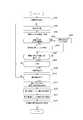
- FIG. 1It is a functional block diagram showing a schematic structure of a living body information measuring device with which vehicles equipment concerning one embodiment of this indication is provided. It is a figure which shows roughly the aorta in a human body. It is a figure which shows an example of the contact state of a to-be-tested part and a contact part. It is a figure which shows another example of the contact state of a to-be-tested part and a contact part. It is a schematic diagram for demonstrating the measurement process of the pulse wave by the biometric information measuring apparatus shown in FIG. It is a flowchart which shows the procedure of the measurement process of the pulse wave by the biometric information measuring apparatus shown in FIG. It is a figure which shows an example of the pulse wave acquired with the sensor.
- FIG. 13is a sectional view taken along line A-A ′ shown in FIG. 12. It is a figure showing an example of composition of equipment for vehicles concerning one embodiment of this indication.
- FIG. 15is a cross-sectional view along the line A-A ′ shown in FIG. 14. It is a figure which shows the other structural example of the equipment for vehicles which concerns on one Embodiment of this indication.
- FIG. 17is a cross-sectional view taken along line A-A ′ shown in FIG. 16. It is a figure showing another example of composition of equipment for vehicles concerning one embodiment of this indication. It is a figure which shows the structural example which acquires a motion factor by the sensor part shown in FIG. It is a flowchart which shows the procedure which performs control according to biometric information. It is a mimetic diagram showing a schematic structure of a living body information measurement system concerning one embodiment of this indication.
- the biological information of a vehicle occupantcan be easily measured.
- the vehicle equipment according to the present embodimentis mounted on vehicles such as automobiles, trains, and airplanes. And the equipment for vehicles concerning this embodiment is provided with the living body information measuring device which measures the living body information of the passenger of vehicles.
- FIG. 1is a functional block diagram showing a schematic configuration of a biological information measuring device provided in a vehicle equipment according to an embodiment.
- the biological information measuring apparatus 1includes a controller 10, a power supply unit 11, a gyro sensor 12, a display unit 14, an audio output unit 16, a communication unit 17, a vibrator 18, and a storage unit. 20.
- the controller 10includes a processor that controls and manages the entire biological information measuring apparatus 1 including each functional block of the biological information measuring apparatus 1.
- the controller 10includes a processor such as a CPU (Central Processing Unit) that executes a program defining a control procedure and a program for measuring biological information of a subject.
- a programis stored in a storage medium such as the storage unit 20, for example.
- the power supply unit 11includes a battery and supplies power to each unit of the biological information measuring apparatus 1.
- the biological information measuring device 1is supplied with electric power from the power supply unit 11 or an external power supply during operation. Further, the power supply unit 11 may receive power supply from the outside through the power supply line and supply the power supplied through the power supply line to each unit of the biological information measuring device 1.
- the gyro sensor 12detects the displacement of the biological information measuring device 1 as a motion factor by detecting the angular velocity of the biological information measuring device 1.
- the gyro sensor 12is, for example, a three-axis vibration gyro sensor that detects an angular velocity from deformation of a structure due to Coriolis force acting on a vibrating arm.
- this structuremay be made of a piezoelectric material such as quartz or piezoelectric ceramic.
- the gyro sensor 12may be formed by MEMS (Micro Electro Mechanical Systems) technology using the structure as a material such as silicon.
- the gyro sensor 12may be another type of gyro sensor such as an optical gyro sensor.
- the controller 10can measure the orientation of the biological information measuring device 1 by integrating the angular velocity acquired by the gyro sensor 12 with respect to time.
- the gyro sensor 12is an angular velocity sensor, for example. However, the gyro sensor 12 is not limited to the angular velocity sensor.
- the gyro sensor 12may detect an angular displacement of the biological information measuring device 1 that is a motion factor. The gyro sensor 12 transmits the detected motion factor to the controller 10.
- the controller 10acquires a motion factor from the gyro sensor 12.
- the motion factorincludes an index indicating the displacement of the biological information measuring device 1 based on the pulsation at the subject site of the subject.
- the controller 10generates a pulsation of the subject based on the motion factor.
- the controller 10measures biological information based on the subject's pulsation. Details of the measurement processing of biological information by the controller 10 will be described later.
- the display unit 14includes a display device such as a liquid crystal display, an organic EL panel (Organic Electro-Luminescence Panel), or an inorganic EL panel (Inorganic Electro-Luminescence panel).
- the display unit 14displays characters, images, symbols, graphics, and the like.
- the display unit 14may be configured with a touch screen display including not only a display function but also a touch screen function. In this case, the touch screen detects contact of the user's finger or stylus pen.
- the touch screencan detect a position where a plurality of fingers, a stylus pen, or the like touches the touch screen.
- the touch screen detection methodmay be any method such as a capacitance method, a resistive film method, a surface acoustic wave method (or an ultrasonic method), an infrared method, an electromagnetic induction method, and a load detection method.
- a capacitance methoda resistive film method
- a surface acoustic wave methodor an ultrasonic method
- an infrared methodan electromagnetic induction method
- a load detection methoda load detection method.
- the voice output unit 16notifies the user or the like by outputting sound.
- the audio output unit 16can be configured with an arbitrary speaker or the like.
- the sound output unit 16outputs the sound signal transmitted from the controller 10 as sound.
- the communication unit 17transmits and receives various data by performing wired communication or wireless communication with an external device.
- the communication unit 17can transmit, for example, a measurement result of biological information measured by the biological information measuring device 1 to an external device.
- the communication part 17can also communicate with the external apparatus which memorize
- the vibrator 18informs the user and the like by generating vibration and the like.
- the vibrator 18presents a tactile sensation to the user of the biological information measuring device 1 by generating vibration or the like at an arbitrary part of the biological information measuring device 1.
- an arbitrary membersuch as an eccentric motor, a piezoelectric element (piezo element), or a linear vibrator can be employed.
- the storage unit 20stores various programs and data including application programs.
- the storage unit 20may include any non-transitory storage medium such as a semiconductor storage medium and a magnetic storage medium.
- the storage unit 20may include a plurality of types of storage media.
- the storage unit 20may include a combination of a portable storage medium such as a memory card, an optical disk, or a magneto-optical disk and a storage medium reader.
- the storage unit 20may include a storage device used as a temporary storage area such as a RAM (Random Access Memory).
- the storage unit 20stores various information and programs for operating the biological information measuring apparatus 1 and also functions as a work memory.
- the storage unit 20may store, for example, data detected by the gyro sensor 12 and measurement results of biological information.
- the biological information measuring apparatus 1is not limited to the configuration illustrated in FIG.
- the biological information measuring apparatus 1 according to an embodimentincludes a controller 10 and a gyro sensor 12. Therefore, in the biological information measuring apparatus 1 according to the embodiment, other components other than the controller 10 and the gyro sensor 12 may be omitted as appropriate, or other components may be added as necessary.
- the display unit 14, the audio output unit 16, the vibrator 18, and the likemay be provided in a vehicle on which the vehicle equipment including the biological information measuring device 1 is mounted.
- the biological information measuring device 1is mounted on a vehicle equipment such as a seat belt that fixes a waist portion from a shoulder of a vehicle occupant, a seat on which the occupant sits, and an armrest that supports the arm of the occupant.
- the biological information measuring device 1measures biological information at a predetermined part (test part) of a passenger who is a subject.
- the test siteis a site that contacts the occupant when measuring the biological information of the occupant using the vehicle equipment.
- the biological information measured by the biological information measuring device 1includes, for example, at least one of a blood component, a pulse wave, a pulse, and a pulse wave propagation velocity.
- the blood componentincludes, for example, a state of sugar metabolism and a state of lipid metabolism.
- the state of glucose metabolismincludes, for example, blood glucose level.
- the state of lipid metabolismincludes, for example, a lipid value. Lipid levels include neutral fat, total cholesterol, HDL (High Density Lipoprotein) cholesterol, LDL (Low Density Lipoprotein) cholesterol, and the like.
- the biological information measuring apparatus 1acquires, for example, a subject's pulse wave as biological information, and measures biological information such as blood components based on the acquired pulse wave.
- the biological information measuring device 1acquires a motion factor in a state where the contact portion provided on the contact surface that contacts the subject is in contact with the test site, and based on the acquired motion factor, the biological information is obtained. taking measurement.
- the biological information measuring apparatus 1may acquire the motion factor in a state where the support portion provided on the contact surface is in contact with the subject at a position different from the test site.
- the biometric information measuring apparatus 1can perform biometric information measurement processing based on, for example, sitting on a passenger's seat, wearing a seat belt, and placing a rider's arm on an armrest. It becomes a state.
- the state in which measurement processing of biological information is possiblerefers to a state in which an application for measuring biological information is activated, for example.
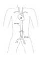
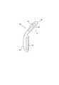
- FIG. 2is a diagram schematically showing the structure in the human body.
- FIG. 2schematically shows the internal structure of a part of the human body.
- FIG. 2also schematically shows in particular a part of the heart and aorta in the human body.
- the blood in the human bodyis delivered from the heart and then supplied to each part of the human body via blood vessels.
- a part of blood delivered from the heartpasses through the thoracic aorta and then passes through the abdominal aorta.
- these blood vesselsundergo fluctuations such as contraction.
- Such fluctuationsare transmitted through the body of the subject, and vary predetermined portions such as the chest, abdomen, thighs, and wrists of the subject. Therefore, the gyro sensor 12 can detect a change in the predetermined part of the subject while the biological information measuring device 1 is pressed against the predetermined part of the subject. In this way, the gyro sensor 12 detects a motion factor resulting from a change in a predetermined part of the subject.
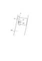
- FIG. 3A and 3Bare diagrams showing an example of a motion factor acquisition mode by the biological information measuring apparatus 1.
- FIG. 3A and 3Bare diagrams showing an example of a motion factor acquisition mode by the biological information measuring apparatus 1.
- 3A and 3Bshow a cross section of a part including an aorta in a living body such as a human body.
- 3A and 3Bshow a state in which the contact surface of the biological information measuring device 1 is in contact with the test site on the surface of the living body (skin). Therefore, as shown in FIGS. 3A and 3B, the contact portion 40 and the support portion 50 provided on the contact surface of the biological information measuring device 1 are in contact with a test site on the surface of the living body (skin). .
- the test site on the surface of the living bodyis the torso of the test subject.
- the aorta shown in FIGS. 3A and 3Bmay be the thoracic aorta shown in FIG. 2 or the abdominal aorta.
- the aorta shown in FIGS. 3A and 3Bmay be the femoral artery, the radial artery, or the ulnar artery.
- the contact portion 40 of the biological information measuring device 1is pressed against a predetermined part of the subject.
- a gyro sensor 12is provided on the back side of the contact portion 40.
- the biological information measuring apparatus 1acquires the displacement of the biological information measuring apparatus 1 as a motion factor using the gyro sensor 12.
- the contact portion 40contacts the test site in the contact state between the biological information measuring apparatus 1 and the predetermined site of the test subject.
- the support unit 50contacts the subject at a position different from the contact unit 40 in the motion factor acquisition state by the biological information measuring apparatus 1.
- the biological information measuring device 1when the biological information measuring device 1 is pressed in the direction of the arrow P at the position of the arrow P and brought into contact with the subject, the biological information measuring device 1 It displaces according to the movement of the expansion and contraction of the blood vessel based on the pulsation.
- the biological information measuring device 1is displaced so that the upper end side rotates as indicated by an arrow Q in FIGS. 3A and 3B with the support portion 50 as a fulcrum.
- the gyro sensor 12 included in the biological information measuring device 1acquires the pulse wave of the subject by detecting the displacement of the biological information measuring device 1.
- the pulse waveis obtained by capturing a change in the volume of the blood vessel caused by the inflow of blood as a waveform from the body surface.
- the gyro sensor 12detects a motion factor caused by a change in a predetermined part (test part) of the subject.
- the gyro sensor 12detects a motion factor resulting from a change in the predetermined part of the subject in a state where the biological information measuring device 1 is pressed against the predetermined part of the subject. Then, the controller 10 performs a measurement process of the biological information of the subject based on the motion factor detected by the gyro sensor 12.
- the test siteincludes the chest, abdomen, thighs, wrists, and the like.
- the variation of the subject site of the subjectincludes not only the variation caused by the movement of the blood vessel of the subject but also at least one of the variation caused by the breathing of the subject and the variation caused by the body movement of the subject. It's okay.
- the subject's blood vesselmay include the subject's aorta.
- the subject's aortamay include at least one of the subject's abdominal aorta, thoracic aorta, femoral artery, radial artery, and ulnar artery.
- the biological information measuring apparatus 1can measure biological information stably with high accuracy by using the subject's aorta as a measurement target.
- the gyro sensor 12is pressed against the subject's test site via the elastic member 19, thereby easily following the change in the subject's test site. Become. Therefore, the biological information measuring device 1 can measure biological information stably with high accuracy.
- the elastic member 19may be any member that generates an elastic force, such as a spring, rubber, flexible resin, one using hydraulic pressure, one using air pressure, one using water pressure, or the like. is there.
- 3Bconnects the housing on which the gyro sensor 12 is installed and the housing on which the gyro sensor 12 is not installed. As shown in FIG. 3B, the housing on which the gyro sensor 12 is installed has a mechanism that is movable around the support portion 50 with respect to the housing on which the gyro sensor 12 is not installed.
- the biological information measuring apparatus 1includes the gyro sensor 12, so that the subject can measure biological information from above the clothes while wearing clothes. That is, according to the biological information measuring apparatus 1, the subject does not need to be undressed when measuring biological information. Moreover, according to the biological information measuring device 1, the subject does not need to touch the measuring device directly to the skin. For this reason, by providing the biological information measuring device 1 in a vehicle equipment for fixing a vehicle occupant such as a seat belt, it is possible to easily measure biological information when the seat belt is worn. In addition, by providing the biological information measuring device 1 in a vehicle equipment that supports a vehicle occupant such as a seat, the biological information can be easily measured when the occupant is seated on the seat. . In addition, by providing the biological information measuring device 1 on a vehicle equipment that supports a part of a vehicle occupant such as an armrest, the biological information is measured when the arm of the occupant is placed on the armrest. It can be done easily.
- the conventional acceleration sensoris not suitable for use as a pulse wave sensor because of its large noise.
- a small acceleration sensor built into a devicesuch as a small terminal is not common when measuring low frequencies around 1 Hz, such as pulse waves and respiration.
- a relatively large acceleration sensoris required for such a purpose.
- the gyro sensor 12is used for measuring biological information.
- a gyro sensorgenerally has little noise during measurement. Since the gyro sensor constantly vibrates (in the case of the vibration type gyro sensor), noise can be reduced due to the structure.
- the gyro sensor 12that can be incorporated in a small housing can be employed.
- the biological information measuring apparatus 1performs a pulse wave measurement process in a state in which the contact portion 40 is in contact with the test site.
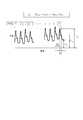
- FIG. 4is a schematic diagram for explaining a pulse wave measurement process performed by the biological information measuring apparatus 1.
- FIG. 5is a flowchart showing a procedure of pulse wave measurement processing by the biological information measuring apparatus 1.
- the horizontal axisrepresents time
- the vertical axisschematically represents the output (rad / second) based on the pulse wave of the angular velocity sensor that is the gyro sensor 12.
- the output of the angular velocity sensorshows only the peak of each pulse wave.
- a predetermined event for the biological information measuring apparatus 1 to start the pulse wave measurement processoccurs at time t 0 .
- Such eventsinclude sitting on the passenger's seat, wearing a seat bell, and placing the passenger's arm on the armrest. Due to the occurrence of such an event, the contact portion 40 of the biological information measuring apparatus 1 is brought into contact with the test site of the passenger who is the test subject. It is assumed that the biological information measuring apparatus 1 is ready to perform the biological information measurement process at time t 0 and starts the pulse wave measurement process.
- the controller 10when the controller 10 starts the pulse wave measurement process, the controller 10 detects the output of the gyro sensor 12 according to the blood vessel pulsation of the subject. During a predetermined period immediately after the start of measurement (from time t 0 to time t 1 in FIG. 4), the output of the gyro sensor 12 is not stabilized due to adjustment of the position where the contact portion 40 contacts the test site. During this period, the pulse wave cannot be acquired accurately. Therefore, the biological information measuring apparatus 1 does not have to use the pulse wave measured during this period, for example, for measuring blood components that are biological information. For example, the biological information measuring apparatus 1 may not store the pulse wave measured during this period in the storage unit 20.
- the controller 10determines whether or not a stable pulse wave has been detected for a predetermined number of times (step S101 in FIG. 5).
- the predetermined number of timesis four in the example shown in FIG. 4, but is not limited thereto.
- a stable pulse waveis a pulse wave in which, for example, variations in peak output of each pulse wave and / or variations in intervals between peaks of each pulse wave are within a predetermined error range.
- the predetermined error range in the interval between peaksis, for example, ⁇ 150 msec, but is not limited thereto.
- the controller 10detects a pulse wave in which the variation in the interval between the peaks of each pulse wave is within four consecutive times within ⁇ 150 msec from time t 1 to time t 2. ing.
- step S102the controller 10 acquires a pulse wave used for measuring a blood component.
- the pulse wave acquisition start timeis, for example, time t 3 in FIG.
- the controller 10may store the pulse wave acquired in this way in the storage unit 20. Since the biological information measuring apparatus 1 starts acquiring pulse waves when it is determined that a stable pulse wave has been detected continuously for a predetermined number of times as described above, it is easy to prevent erroneous detection.
- the controller 10After starting the acquisition of the pulse wave, the controller 10 ends the acquisition of the pulse wave when the pulse wave acquisition end condition is satisfied.
- the end conditionmay be, for example, a case where a predetermined time has elapsed after starting the acquisition of the pulse wave.
- the end conditionmay be, for example, a case where pulse waves for a predetermined pulse rate are acquired.
- the termination conditionis not limited to this, and other conditions may be set as appropriate.
- the controller 10from the time t 3 a predetermined time (e.g. 8 seconds or 15 seconds) to end the acquisition of the pulse wave at the time t 4 after the passage. Thereby, the flow shown in FIG. 5 ends.
- step S101 in FIG. 5the controller 10 starts the pulse wave measurement process. It is determined whether or not a predetermined time has elapsed since the occurrence of the event (step S103).
- step S103When the controller 10 determines that a predetermined time (for example, 30 seconds) has not elapsed since the occurrence of a predetermined event for starting the pulse wave measurement process (No in step S103), the flow shown in FIG. The process proceeds to S101.
- a predetermined timefor example, 30 seconds
- step S103if the controller 10 cannot detect a stable pulse wave even after a predetermined time has elapsed since the occurrence of a predetermined event for starting the pulse wave measurement process (Yes in step S103), the controller 10 automatically performs the measurement process. Is terminated (timed out), and the flow of FIG. 5 is terminated.
- FIG. 6is a diagram illustrating an example of a pulse wave acquired at a test site (body) using the biological information measuring apparatus 1.
- FIG. 6is a diagram illustrating an example of a pulse wave when the gyro sensor 12 is used as a pulsation detecting unit.
- FIG. 6is obtained by integrating the angular velocities acquired by the angular velocity sensor that is the gyro sensor 12.
- the horizontal axisrepresents time
- the vertical axisrepresents the angle. Since the acquired pulse wave may include noise caused by the body movement of the subject, for example, correction by a filter that removes a DC (Direct Current) component may be performed to extract only the pulsation component.
- DCDirect Current
- the biological information measuring apparatus 1calculates an index based on the pulse wave from the acquired pulse wave, and measures a blood component using the index based on the pulse wave.
- a method of calculating an index based on the pulse wave from the acquired pulse wavewill be described with reference to FIG.
- the propagation of the pulse waveis a phenomenon in which the pulsation caused by the blood pushed out of the heart is transmitted through the wall of the artery or blood.
- the pulsation caused by the blood pushed out of the heartreaches the periphery of the limb as a forward wave, and a part of the pulsation is reflected by the branching portion of the blood vessel, the blood vessel diameter changing portion, etc., and returns as a reflected wave.
- the index based on the pulse waveis, for example, the pulse wave velocity PWV (Pulse Wave Velocity) of the forward wave, the magnitude P R of the reflected wave of the pulse wave, the time difference ⁇ t between the forward wave and the reflected wave of the pulse wave, It is AI (Augmentation Index) represented by the ratio of the magnitude of the forward wave and the reflected wave.
- PWVPulse Wave Velocity
- AIAbsolute Wave Velocity
- the pulse wave shown in FIG. 6is a pulse for n times of the user, and n is an integer of 1 or more.
- the pulse waveis a composite wave in which a forward wave generated by ejection of blood from the heart and a reflected wave generated from a blood vessel branch or a blood vessel diameter changing portion overlap.
- P Fnis the magnitude of the peak of the pulse wave due to the forward wave of each pulse
- P Rnis the peak of the pulse wave due to the reflection wave of each pulse magnitude
- P Snis the minimum value of the pulse wave for each pulse is there.
- T PRis the pulse peak interval.
- the index based on the pulse waveincludes a quantified information obtained from the pulse wave.
- PWVwhich is one of indices based on pulse waves
- PWVis calculated based on the difference in propagation time of pulse waves measured at two test sites such as the upper arm and ankle and the distance between the two points.
- PWVis acquired by synchronizing pulse waves (for example, the upper arm and ankle) at two points in the artery, and the difference in distance (L) between the two points is divided by the time difference (PTT) between the two points. Is calculated.
- the reflected wave which is an index based on the pulse wave magnitude P Rmay calculate the magnitude of P Rn of the peak of the pulse wave due to the reflected wave, the P Rave averaged n times amount It may be calculated.
- the time difference ⁇ t between the forward wave and the reflected wave of the pulse wave, which is one of the indicators based on the pulse wavemay be calculated as a time difference ⁇ t n in a predetermined pulse, or ⁇ t obtained by averaging n time differences. ave may be calculated.
- AI nis the AI for each pulse.
- the pulse wave propagation velocity PWV, the magnitude of the reflected wave P R , the time difference ⁇ t between the forward wave and the reflected wave, and AIchange depending on the hardness of the blood vessel wall, and therefore are used to estimate the state of arteriosclerosis. Can do. For example, if the blood vessel wall is hard, the pulse wave propagation speed PWV increases. For example, if the blood vessel wall is hard, the magnitude P R of the reflected wave increases. For example, if the blood vessel wall is hard, the time difference ⁇ t between the forward wave and the reflected wave becomes small. For example, if the blood vessel wall is hard, AI increases.
- the biological information measuring apparatus 1can estimate the state of arteriosclerosis and the blood fluidity (viscosity) using an index based on these pulse waves.
- the biological information measuring apparatus 1uses the change of the index based on the pulse wave acquired in the same subject site of the same subject and the period when the arteriosclerosis state does not substantially change (for example, within several days). Changes in fluidity can be estimated.
- the blood fluidityindicates the ease of blood flow. For example, when the blood fluidity is low, the pulse wave propagation velocity PWV is small. For example, the low fluidity of the blood, the size P R of the reflected wave is reduced. For example, when the blood fluidity is low, the time difference ⁇ t between the forward wave and the reflected wave becomes large. For example, when blood fluidity is low, AI becomes small.
- the biological information measurement apparatus 1calculates a pulse wave propagation velocity PWV, a reflected wave magnitude P R , a time difference ⁇ t between a forward wave and a reflected wave, and AI.
- the index based on the pulse waveis not limited to this.
- the biological information measuring apparatus 1may use posterior systolic blood pressure as an index based on pulse waves.
- FIG. 7is a diagram illustrating the time variation of the calculated AI.
- the pulse wavewas acquired for about 5 seconds using the biological information measuring device 1 including an angular velocity sensor.
- the controller 10calculated AI for each pulse from the acquired pulse wave, and further calculated an average value AI ave thereof.
- the biological information measuring apparatus 1acquires a pulse wave at a plurality of timings before and after a meal, and uses an average value of AI (hereinafter referred to as AI) as an example of an index based on the acquired pulse wave. Calculated.
- the horizontal axis of FIG. 7shows the passage of time, with the first measurement time after meal being zero.
- the vertical axis in FIG. 7indicates the AI calculated from the pulse wave acquired at that time.
- the biological information measuring apparatus 1acquires a pulse wave before a meal, immediately after a meal, and every 30 minutes after a meal, and calculates a plurality of AIs based on each pulse wave.
- the AI calculated from the pulse wave acquired before the mealwas about 0.8. Compared to before the meal, the AI immediately after the meal was small, and the AI reached the minimum extreme value about 1 hour after the meal. The AI gradually increased until the measurement was completed 3 hours after the meal.
- the biological information measuring apparatus 1can estimate a change in blood fluidity from the calculated change in AI. For example, when the red blood cells, white blood cells, and platelets in the blood harden in a dumpling shape or the adhesive strength increases, the fluidity of blood decreases. For example, when the water content of plasma in blood decreases, blood fluidity decreases. These changes in blood fluidity change depending on the health condition of the subject such as the glycolipid state, heat stroke, dehydration, and hypothermia described below. Before the health condition of the subject becomes serious, the subject can know the change in fluidity of his / her blood using the biological information measuring apparatus 1 according to one embodiment. From the change in AI before and after the meal shown in FIG.
- the biological information measuring devicemay report a state where the blood fluidity is low and a state where the blood fluidity is high.
- the biological information measuring apparatus 1may determine whether the blood fluidity is low or the blood fluidity is high based on the average value of AI at the actual age of the subject.
- the biological information measuring apparatus 1may determine that the blood fluidity is high if the calculated AI is larger than the average value, and the blood fluidity is low if the calculated AI is smaller than the average value.
- the biological information measuring apparatus 1may determine, for example, the determination of a state where the blood fluidity is low and a state where the blood fluidity is high based on the AI before meal.
- the biological information measuring device 1may estimate the degree of low blood fluidity by comparing the AI after meal with the AI before meal.
- the biological information measuring apparatus 1can use, for example, AI before meal, that is, fasting AI, as an index of the blood vessel age (blood vessel hardness) of the subject.
- the biological information measuring apparatus 1calculates the change amount of the calculated AI based on the AI before the subject's meal, that is, the fasting AI, as a reference, and the blood vessel age (hardness of the blood vessel) of the subject.
- the estimation error due tocan be reduced.
- the biological information measuring apparatus 1can estimate a change in blood fluidity with higher accuracy.
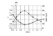
- FIG. 8is a diagram showing the calculated AI and blood glucose level measurement results.
- the pulse wave acquisition method and the AI calculation methodare the same as those in the embodiment shown in FIG.
- the vertical axis on the right side of FIG. 8indicates the blood glucose level in the blood, and the vertical axis on the left side indicates the calculated AI.
- the solid line in FIG. 8shows the AI calculated from the acquired pulse wave, and the dotted line shows the measured blood glucose level.
- the blood glucose levelwas measured immediately after acquiring the pulse wave.
- the blood glucose levelwas measured using a blood glucose meter “Medisafefit” (registered trademark) manufactured by Terumo. Compared with the blood glucose level before the meal, the blood glucose level immediately after the meal is increased by about 20 mg / dl. The blood glucose level reached its maximum extreme value about 1 hour after the meal. Thereafter, the blood glucose level gradually decreased until the measurement was completed, and became approximately the same as the blood glucose level before the meal about 3 hours after the meal.
- the blood glucose level after the pre-mealhas a negative correlation with the AI calculated from the pulse wave.
- the blood glucose levelincreases, red blood cells and platelets harden in the form of dumplings due to sugar in the blood, or the adhesive strength increases, and as a result, the blood fluidity may decrease.
- the pulse wave velocity PWVmay decrease.
- the pulse wave propagation velocity PWVdecreases, the time difference ⁇ t between the forward wave and the reflected wave may increase.
- the size P R of the reflected wave with respect to the size P F of the forward wavemay be less.
- AImay be smaller. Since AI within several hours after a meal (3 hours in one embodiment) has a correlation with blood glucose level, the fluctuation of blood glucose level of the subject can be estimated by the fluctuation of AI. Further, if the blood glucose level of the subject is measured in advance and the correlation with the AI is acquired, the biological information measuring apparatus 1 can estimate the blood glucose level of the subject from the calculated AI.
- the biological information measuring device 1can estimate the state of glucose metabolism of the subject.
- the biological information measuring apparatus 1estimates, for example, a blood glucose level as the state of sugar metabolism.
- a predetermined time or morefor example, about 1.5 hours or more after a meal
- the biological information measuring device 1can be estimated that the subject has an abnormal glucose metabolism (diabetic patient).
- the biological information measuring apparatus 1determines the subject's information.
- the state of glucose metabolismcan be estimated.
- a predetermined numbere.g., 0.5 or more
- it can be estimated that the subject is a glucose metabolism abnormalitypostprandial hyperglycemia patient.
- FIG. 9is a diagram showing the relationship between the calculated AI and blood glucose level.
- the calculated AI and blood glucose levelare acquired within 1 hour after a meal with a large fluctuation in blood glucose level.
- the data in FIG. 9includes data after a plurality of different meals in the same subject.
- the calculated AI and blood glucose levelshowed a negative correlation.
- the correlation coefficient between the calculated AI and blood glucose levelwas 0.9 or more. For example, if the correlation between the calculated AI and the blood glucose level as shown in FIG. 9 is obtained in advance for each subject, the biological information measuring apparatus 1 calculates the blood glucose level of the subject from the calculated AI. Can also be estimated.
- FIG. 10is a diagram showing measurement results of the calculated AI and triglyceride value.
- the pulse wave acquisition method and the AI calculation methodare the same as those in the embodiment shown in FIG.
- the vertical axis on the right side of FIG. 10indicates the neutral fat level in the blood, and the vertical axis on the left side indicates AI.
- the solid line in FIG. 10indicates the AI calculated from the acquired pulse wave, and the dotted line indicates the measured triglyceride value.
- the neutral fat valuewas measured immediately after acquiring the pulse wave.
- the neutral fat valuewas measured using a lipid measuring device “Pocket Lipid” manufactured by Techno Medica. Compared to the neutral fat value before meal, the maximum extreme value of the neutral fat value after meal is increased by about 30 mg / dl. About 2 hours after the meal, the neutral fat reached its maximum extreme value. Thereafter, the triglyceride value gradually decreased until the measurement was completed, and became approximately the same as the triglyceride value before the meal at about 3.5
- the first minimum extreme value AI P1was detected about 30 minutes after the meal, and the second minimum extreme value AI P2 was detected about 2 hours after the meal.
- First minimum extreme AI P1 of which has been detected in about 30 minutes after mealcan be estimated to be due to the influence of the blood glucose level after meal described above.
- the second minimum extreme value AI P2 detected about 2 hours after the mealalmost coincides with the maximum extreme value of neutral fat detected about 2 hours after the meal. From this, it can be estimated that the second minimum extreme value AI P2 detected after a predetermined time from the meal is due to the influence of neutral fat.
- the triglyceride level after the pre-mealhas a negative correlation with the AI calculated from the pulse wave, like the blood glucose level.
- the minimum extreme value AI P2 of AI detected after a predetermined time from a mealis correlated with the triglyceride value.
- the fluctuation of the triglyceride valuecan be estimated.
- the biological information measuring apparatus 1estimates the neutral fat value of the subject from the calculated AI. Can do.
- the biological information measuring apparatus 1can estimate the lipid metabolism state of the subject.
- the biological information measuring apparatus 1estimates a lipid value, for example, as the state of lipid metabolism.
- a lipid valuefor example, as the state of lipid metabolism.
- the biological information measuring apparatus 1determines that the subject is a lipid It can be estimated that this is a metabolic disorder (hyperlipidemic patient).
- AI B mealis before the AI, based on the difference between the second minimum extremes AI P2 which is detected after the predetermined post-mealtime (AI B -AI P2), the biological information measuring apparatus 1 is subject
- the state of lipid metabolismcan be estimated.
- lipid metabolism abnormalityfor example, when (AI B -AI P2 ) is 0.5 or more, the biological information measuring apparatus 1 estimates that the subject has lipid metabolism abnormality (postprandial hyperlipidemia patient). it can.
- the biological information measuring apparatus 1is based on the first minimum extreme value AI P1 detected earliest after a meal and the generation time thereof.
- the state of sugar metabolism of a personcan be estimated.
- the biological information measuring apparatus 1 according to the embodimentis configured so that the subject is based on the second minimum extreme value AI P2 detected after a predetermined time after the first minimum extreme value AI P1 and the generation time thereof.
- the state of lipid metabolismcan be estimated.
- the case of neutral fathas been described as an example of estimation of lipid metabolism, but the estimation of lipid metabolism is not limited to neutral fat.
- the lipid value estimated by the biological information measuring device 1includes, for example, total cholesterol, HDL cholesterol, LDL cholesterol, and the like. These lipid values show a tendency similar to that of the neutral fat described above.
- FIG. 11is a flowchart showing a procedure for estimating blood fluidity, sugar metabolism and lipid metabolism based on AI. With reference to FIG. 11, the flow of blood fluidity and the estimation of the state of sugar metabolism and lipid metabolism by the biological information measuring apparatus 1 according to an embodiment will be described.
- the biological information measuring apparatus 1acquires the AI reference value of the subject as an initial setting (step S201).
- the average AI estimated from the age of the subjectmay be used as the AI reference value, or the fasting AI of the subject acquired in advance may be used.
- the biological information measuring apparatus 1may use the AI determined to be before meals in steps S202 to S208 as the AI reference value, or may use the AI calculated immediately before the pulse wave measurement as the AI reference value. In this case, the biological information measuring apparatus 1 executes step S201 after steps S202 to S208.
- the biological information measuring device 1acquires a pulse wave (step S202). For example, the biological information measuring apparatus 1 determines whether or not a predetermined amplitude or more has been obtained for a pulse wave acquired during a predetermined measurement time (for example, 5 seconds). The biological information measuring device 1 proceeds to step S203 when a predetermined amplitude or more is obtained for the acquired pulse wave. The biological information measuring apparatus 1 repeats step S202 if these amplitudes are not greater than the predetermined amplitude (these steps are not shown). In step S202, for example, when the biological information measuring apparatus 1 detects a pulse wave having a predetermined amplitude or more, the biological information measuring apparatus 1 automatically acquires the pulse wave.
- a predetermined measurement timefor example, 5 seconds.
- the biological information measuring device 1proceeds to step S203 when a predetermined amplitude or more is obtained for the acquired pulse wave.
- the biological information measuring apparatus 1repeats step S202 if these amplitudes are not greater than the predetermined amplitude (these steps are not shown).
- the biological information measuring apparatus 1calculates AI as an index based on the pulse wave from the pulse wave acquired in step S202 and stores it in the storage unit 20 (step S203).
- the biological information measuring device 1may calculate the AI at a specific pulse.
- the AImay be corrected by, for example, the pulse rate P R , the pulse pressure (P F ⁇ P S ), the body temperature, the temperature of the test site, and the like. It is known that both pulse and AI and pulse pressure and AI have a negative correlation, and temperature and AI have a positive correlation.
- the biological information measuring apparatus 1calculates a pulse and a pulse pressure in addition to the AI.
- the biological information measuring apparatus 1may be equipped with a temperature sensor together with the gyro sensor 12, and may acquire the temperature of the test site when acquiring the pulse wave in step S202.
- the biological information measuring apparatus 1corrects AI by substituting the acquired pulse, pulse pressure, temperature, and the like into a correction formula created in advance.
- the biological information measuring device 1compares the AI reference value acquired in step S201 with the AI calculated in step S203, and estimates the blood fluidity of the subject (step S204).
- the calculated AIis larger than the AI reference value (in the case of YES)
- the biological information measuring apparatus 1notifies that the blood fluidity is high, for example (step S205).
- the calculated AIis not larger than the AI reference value (in the case of NO)
- the biological information measuring apparatus 1notifies that blood fluidity is low, for example (step S206).
- the biological information measuring apparatus 1confirms with the subject whether or not to estimate the state of sugar metabolism and lipid metabolism (step S207).
- the biological information measuring device 1ends the process.
- the biological information measuring apparatus 1checks whether the calculated AI is acquired before or after a meal (step S208). When it is not after meal (before meal) (in the case of NO), the process returns to step S202, and the biological information measuring apparatus 1 acquires the next pulse wave.
- the biological information measuring apparatus 1stores the pulse wave acquisition time corresponding to the calculated AI (step S209). Then, when acquiring a pulse wave (in the case of NO at step S210), the process returns to step S202, and the biological information measuring device 1 acquires the next pulse wave. When the pulse wave measurement is finished (in the case of YES at step S210), the process proceeds to step S211 and subsequent steps, and the biological information measuring apparatus 1 estimates the sugar metabolism and lipid metabolism of the subject.
- the biological information measuring apparatus 1extracts the minimum extreme value and its time from the plurality of AIs calculated in Step S204 (Step S211). For example, when the AI as shown by the solid line in FIG. 10 is calculated, the biological information measuring apparatus 1 determines the first minimum extreme value AI P1 about 30 minutes after the meal and the second minimum about 2 hours after the meal. The extreme value AI P2 is extracted.
- the biological information measuring apparatus 1estimates the sugar metabolism state of the subject from the first minimum extreme value AI P1 and the time (step S212). Furthermore, the biological information measuring apparatus 1 estimates the lipid metabolism state of the subject from the second minimum extreme value AI P2 and the time (step S213).
- An example of estimating the state of sugar metabolism and lipid metabolism of the subjectis the same as that in FIG.
- the biological information measuring apparatus 1notifies the estimation results of step S212 and step S213 (step S214), and ends the process shown in FIG.
- the notificationis performed by the audio output unit 16.
- the audio output unit 16reports, for example, “normal sugar metabolism”, “suspected abnormal sugar metabolism”, “normal lipid metabolism”, “suspected abnormal lipid metabolism”, and the like. Further, the voice output unit 16 may notify advice such as “Let's consult a hospital” and “Let's review the diet”. Then, the biological information measuring device 1 ends the process shown in FIG.
- an audio output unit that performs audio notificationan audio system that is provided in advance in a vehicle, such as car audio, may be used.
- the audio signal from the biological information measuring device 1may be input to the AUX terminal of the audio system via the AUX cable. Further, the audio signal from the biological information measuring device 1 may be transmitted to the audio system by an arbitrary wireless connection such as an FM transmitter or Bluetooth (registered trademark).
- a dedicated sound output unitthat outputs sound from the biological information measuring device 1 may be provided.
- the notificationmay be performed by displaying on the display unit 14 instead of the notification by the voice as described above or together with the notification by the voice.
- a display used as a vehicle-mounted television or a car navigation systemmay be used as a display unit that performs notification by display.
- a dedicated display unit that displays a notification from the biological information measuring device 1may be provided.
- the biological information measuring apparatus 1may cause the audio output unit 16 to output a sound indicating that the gyro sensor 12 detects a motion factor. Thereby, in the biological information measuring apparatus 1, the subject can easily and clearly know that the gyro sensor 12 is correctly detecting the motion factor.
- the biological information measured by the biological information measuring device 1may include information on at least one of the pulse wave, pulse, respiration, heartbeat, pulse wave propagation speed, and blood flow of the subject.
- the controller 10is based on the biological information measured by the biological information measuring device 1, the subject's physical condition, drowsiness, sleep, wakefulness, psychological state, physical state, emotion, mind-body state, mental state, autonomic nerve, Information regarding at least one of a stress state, a conscious state, a blood component, a sleep state, a respiratory state, and a blood pressure may be estimated.
- the “physical state” of the subjectmeans, for example, the presence or absence of symptoms such as heat stroke, fatigue, altitude sickness, diabetes, metabolic syndrome, the degree of these symptoms, and the presence or absence of signs of these symptoms And so on.
- the blood componentcan be neutral fat, blood sugar level, or the like.
- the arrangement of the gyro sensor 12is important when measuring biological information of a passenger who is a subject, and any other configuration of the biological information measuring apparatus 1 can be used as long as it can operate according to the control of the controller 10. It can be placed at a location. Therefore, below, arrangement
- FIG. 12is a diagram illustrating a configuration example of a vehicle equipment including the biological information measuring device 1.
- FIG. 12shows an example in which the vehicle equipment 100 is a three-point seat belt that fixes the waist portion from the shoulder of the passenger.
- the vehicle equipment 100 as a seat beltincludes a shoulder belt 101 extending from one shoulder of the occupant to the waist on the opposite side, and a waist belt 102 hung on the occupant's waist.
- the gyro sensor 12is provided on at least one of the shoulder belt 101 and the waist belt 102 so that the contact portion 40 contacts the passenger who is the subject.
- FIG. 12shows an example in which the gyro sensor 12 is provided on both the shoulder belt 101 and the waist belt 102.
- the gyro sensor 12When the gyro sensor 12 is provided on the shoulder belt 101, the gyro sensor 12 may be provided so as to be positioned near the chest of the passenger. Further, when the gyro sensor 12 is provided on the waist belt 102, the gyro sensor 12 may be provided so as to be positioned in the vicinity of the abdomen of the occupant (above the navel).
- the waist belt 102shows an example of a configuration in which a sensor fixing unit 103 for fixing the gyro sensor 12 is installed. In this case, the gyro sensor 12 is fixed by the sensor fixing unit 103.
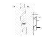
- FIG. 13is a cross-sectional view of the sensor fixing portion 103 along the line A-A ′ shown in FIG.
- the sensor fixing unit 103includes a holding unit 103 a that holds the waist belt 102, and a holding unit 103 b that is connected to the holding unit 103 a and holds the gyro sensor 12.
- the holding unit 103 aholds the waist belt 102 so that the holding position can be adjusted along the waist belt 102.
- the holding portion 103bis connected to the holding portion 103a via the holding portion 103a and the connecting portion so that the abutting portion 40 comes into contact with, for example, an abdomen (upwardly of the subject's navel) that is a test portion of the passenger.
- the gyro sensor 12is held.
- the holding portion 103bis urged by the connecting portion in a direction to close toward the holding portion 103a (the direction of the arrow shown in FIG. 13). That is, the holding portion 103b is provided by being urged in a direction in which the holding portion 103b is pressed against the passenger. Therefore, when the sensor fixing unit 103 is pressed against the passenger, the holding unit 103b is expanded in the direction opposite to the arrow shown in FIG. For this reason, the contact portion 40 comes into contact with the test site of the passenger with an appropriate pressure by the restoring force of the connecting portion that connects the holding portion 103a and the holding portion 103b.
- the sensor fixing unit 103is installed on the waist belt 102.
- the waist belt 102 and the sensor fixing unit 103may be integrally provided.
- the gyro sensor 12may be arrange
- FIG. 14is a diagram illustrating a configuration example when the gyro sensor 12 is detachably disposed on the seat belt 100 (the waist belt 102).
- FIG. 14shows an example in which the gyro sensor 12 is held by a clip-shaped sensor fixing portion 104 that holds (clamps) the waist belt 102.
- FIG. 15is a cross-sectional view of the sensor fixing portion 104 along the line A-A ′ shown in FIG.
- the sensor fixing portion 104includes a clip portion 104 a that holds the waist belt 102 and a holding portion 104 b that holds the gyro sensor 12.
- the clip portion 104ais urged by a torsion spring 105, and sandwiches the waist belt 102 by a pair of sandwiching pieces that can rotate around the rotation shaft 106.
- the holding portion 104bis configured so that the abutment portion 40 abuts, for example, the abdomen (upward of the subject's navel), which is a test portion of the occupant, with the clip portion 104a holding the waist belt. 12 is held.
- the holding portion 104bis urged by the connecting portion in a direction to close toward the clip portion 104a (the direction of the arrow shown in FIG. 15). That is, the holding portion 104b is provided by being biased in a direction in which the holding portion 104b is pressed against the passenger. Therefore, when the sensor fixing unit 104 is pressed against the passenger, the holding unit 104b is expanded in the direction opposite to the arrow shown in FIG. Therefore, the abutment portion 40 abuts the occupant's test site with an appropriate pressure by the restoring force of the connecting portion that couples the retention portion 104a and the retention portion 104b.
- FIGS. 13 and 15show an example in which the gyro sensor 12 is provided in the vehicle equipment 100 (sensor fixing portions 103 and 104) (therefore, the gyro sensor 12 is indicated by a broken line), but is limited to this. It is not a thing.
- the gyro sensor 12may be provided outside the vehicle equipment 100, that is, so as to be exposed from the surface of the vehicle equipment 100.
- a portion (contact portion, contact surface) where the gyro sensor 12 abuts on the subject site of the subjectmay be provided so as to be exposed from the surface of the vehicle equipment 100.
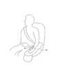
- FIG. 16is a diagram illustrating another configuration example of the vehicle equipment including the biological information measuring device 1.
- FIG. 16shows an example in which the vehicle equipment 200 is a seat that supports a seated passenger.
- the vehicle equipment 200 as a seat on which a passenger sitsincludes a seat cushion portion 201, a seat back portion 202, and a headrest portion 203.
- the seat cushion part 201is a seating part that supports the back side part of the thigh from the seated passenger's buttocks.
- the seat back part 202is a backrest part which supports the back part of the seated passenger.
- the headrest part 203supports the head of the seated passenger.
- the gyro sensor 12is provided in at least one of the seat cushion part 201, the seat back part 202, and the headrest part 203.
- FIG. 16shows an example in which the gyro sensor 12 is provided in the seat cushion portion 201 and the seat back portion 202. When the gyro sensor 12 is not provided in the headrest part 203, the headrest part 203 itself may not be provided.
- the gyro sensor 12When the gyro sensor 12 is provided in the seat cushion part 201, the gyro sensor 12 may be disposed so as to contact the back side of the thigh part of the seated passenger. The thigh artery passes through the thigh. For this reason, the gyro sensor 12 provided in the seat cushion part 201 can detect a motion factor from the fluctuation
- the gyro sensor 12When the gyro sensor 12 is provided in the seat back portion 202, the gyro sensor 12 may be disposed so as to contact the back portion corresponding to the thoracic aorta or the abdominal aorta of the seated passenger. In this case, the gyro sensor 12 provided in the seat back portion 202 can detect the motion factor from the fluctuation of the back portion accompanying the fluctuation of the thoracic aorta or the abdominal aorta.
- FIG. 17is a cross-sectional view of the seat back portion 202 along the line A-A ′ shown in FIG.
- the gyro sensor 12is provided so that the contact portion 40 contacts, for example, the back portion of the seated passenger.
- the gyro sensor 12is urged by a torsion spring 204 and is provided so as to be rotatable about a rotation shaft 205.
- FIG. 17shows an example in which the gyro sensor 12 is provided inside the vehicle equipment 200 (seat back portion 202), but is not limited thereto.
- the gyro sensor 12may be provided outside the vehicle equipment 200 (the seat cushion portion 201, the seat back portion 202, and the headrest portion 203), that is, so as to be exposed from the surface of the vehicle equipment 200.
- FIG. 18is a diagram illustrating another configuration example of the vehicle equipment including the biological information measuring device 1.
- FIG. 18shows an example in which the vehicle equipment 300 is an armrest that supports the arm of the passenger.
- the vehicle equipment 300 as an armrestsupports the arm of the seated passenger.
- the vehicle equipment 300is provided with a sensor unit 301 so as to come into contact with, for example, the wrist portion of the rider with the arm placed on the vehicle equipment 300 (armrest).
- the radial artery and the ulnar arterypass through the wrist.
- the sensor unit 301includes the gyro sensor 12 and detects a motion factor from a change in the wrist part due to a change in the radial artery and the ulnar artery. This motion factor is used, for example, for detecting the blood pressure of the passenger.
- FIG. 19is a diagram showing a configuration example for acquiring a motion factor by the sensor unit 301 provided in the armrest shown in FIG.
- a fixed portion 302 fixed to the vehicle equipment 300is provided so as to protrude from the vehicle equipment 300 which is an armrest.
- a support member 304is connected to the fixed portion 302 via a torsion coil spring 303.
- the support member 304is connected to the fixed portion 302 by a torsion coil spring 303 so as to be rotatable about the rotation shaft 305.
- a placement portion 306 for placing a passenger's wristis provided in contact with the vehicle equipment 300 and the fixed portion 302.
- the support member 304is provided so that one end portion protrudes from the placement portion 306.
- the contact portion 40is provided on one surface of one end of the support member 304 protruding from the placement portion 306, and the gyro sensor 12 is provided on the other surface.
- the mounting portion 306connects the vehicle equipment 300 that is an armrest and the fixing portion 302 so that they are fixed at an appropriate angle.
- the abutment portion 40 protruding from the placement portion 306contacts the occupant's wrist portion.
- the gyro sensor 12detects the motion factor from the fluctuation of the wrist portion of the passenger that contacts the contact portion 40.
- the controller 10measures a passenger
- the measurement of the biological information using the vehicle equipment 300 that is an armrestis performed, for example, in a situation where the driver who is a passenger is not driving the vehicle (before starting the driving of the vehicle or while the vehicle is stopped).
- the biological informationcan be measured without the vehicle occupant performing a special action for measuring the biological information.
- biometric informationis obtained by actions generally performed while riding a vehicle, such as seating on a seat, wearing a seat belt, and placing an arm on an armrest. Can be measured. Therefore, it is possible to easily measure biological information.
- the controller 10By measuring the biological information of a vehicle occupant, in particular, the driver, safety can be improved, such as prevention of snoozing driving and physical condition management of the driver. Based on the motion factor detected by the gyro sensor 12, the controller 10 detects at least one of the driver's sleep and drowsiness as biological information, and performs control according to the detected biological information.
- FIG. 20is a flowchart showing an operation example of control according to the biological information by the biological information measuring apparatus 1.
- the waist belt 102is provided with the gyro sensor 12.
- the controller 10confirms whether the seat belt is worn and the gyro sensor 12 provided on the waist belt 102 is normally worn on the abdomen of the passenger. For example, the controller 10 is normally attached to the gyro sensor 12 based on whether or not a stable pulse wave can be continuously measured a predetermined number of times based on the motion factor detected by the gyro sensor 12 provided on the waist belt 102. It is confirmed whether or not (step S301).
- the controller 10measures biological information such as body movement, pulse, and respiration based on the motion factor detected by the gyro sensor 12 (step S302).
- the controller 10determines whether or not a predetermined time has passed since the biological information was measured, or a predetermined number of pieces of biological information data have been acquired (step S303).
- the controller 10When the predetermined time has not elapsed since the biological information was measured, or the data of the predetermined number of biological information has not been acquired (No in step S303 in FIG. 20), the controller 10 performs the process in step S302. Transition.
- step S304When a predetermined amount of time has elapsed since the measurement of the biological information and data of a predetermined number of biological information has been acquired (Yes in step S303 in FIG. 20), the controller 10 is the subject based on the acquired biological information. The sleepiness, fatigue, physical condition, etc. of a certain passenger (driver) are estimated (step S304).
- the controller 10determines whether or not an abnormality has occurred in the driver from the estimation results of the driver's sleepiness, fatigue, physical condition, and the like (step S305). Since various methods are known as methods for detecting the occurrence of abnormalities (for example, falling asleep) from drowsiness, fatigue, physical condition, etc., description thereof is omitted here.
- step S305 in FIG. 20the controller 10 proceeds to the process in step S302.
- step S305 in FIG. 20If it is determined that an abnormality has occurred (Yes in step S305 in FIG. 20), the controller 10 notifies the passenger such as the driver of the occurrence of the abnormality (step S306).
- step S307the process is terminated.
- the controller 10confirms that the seat belt is released (step S307). For example, when the motion factor cannot be obtained from the gyro sensor 12 disposed on the waist belt 102, the controller 10 confirms the release of the seat belt.
- the controller 10when the air conditioner is mounted on the vehicle, the controller 10 performs control to lower the temperature in the vehicle. Moreover, the controller 10 outputs a warning sound etc. when the audio
- the controller 10causes the vibrator to vibrate when a vibrator capable of imparting vibration to the passenger is mounted on the vehicle.
- a vibratorany member such as an eccentric motor, a piezoelectric element (piezo element), or a linear vibrator can be adopted as long as it generates vibration.
- the controller 10may perform control such as stopping the vehicle on the road shoulder.
- FIG. 21is a schematic diagram illustrating a schematic configuration of a biological information measurement system according to an embodiment of the present disclosure.
- the biological information measurement system 400 of one embodiment shown in FIG. 21includes a vehicle equipment 410, an external device 420, and a communication network.
- the vehicle equipment 410is a device such as a seat belt, a seat, and an armrest that is mounted on a vehicle such as an automobile, a train, and an airplane and that fixes or supports the passenger.
- the vehicle equipment 410detects a motion factor resulting from a change in a predetermined part of the passenger. For this reason, the vehicle equipment 410 includes the gyro sensor 12.
- the vehicle equipment 410includes a communication unit (which can be wired or wirelessly connected), and transmits the detected motion factor to the external device 420.
- the external device 420performs various calculations related to the measurement of biological information based on the received motion factor.
- the external device 420includes various necessary functional units including a controller (for example, a processor such as a CPU).
- a controllerfor example, a processor such as a CPU
- FIG. 21it is assumed that the vehicle equipment 410 and the external device 420 are connected by wireless communication, but the biological information measurement system 400 is not limited to such a configuration.
- the vehicle equipment 410 and the external device 420may be connected by a wired connection such as a predetermined cable.
- the biological information measurement system 400includes the vehicle equipment 410 and the external device 420.
- the vehicle equipment 410includes the gyro sensor 12.
- the gyro sensor 12detects a motion factor resulting from a change in the predetermined part of the passenger while the vehicle equipment 410 is in contact with the predetermined part of the passenger.
- the external device 420includes the above-described controller.
- the external device 420has an artificial intelligence function, a machine learning function, a deep learning function, and the like, and performs various operations related to measurement of biological information by a statistically obtained algorithm based on the motion factor received from the vehicle equipment 410. You can go.
- the vehicle equipment 100 to 300 including the biological information measuring device 1 (the controller 10 and the gyro sensor 12) and the biological information measuring system 400have been described.
- the embodiment of the present disclosuremay be implemented as a biological information measuring method by the biological information measuring device 1 including the gyro sensor 12.
- the biological information measuring device 1 including the gyro sensor 12in the state where the biological information measuring device 1 is pressed against a predetermined part of the passenger who is the subject, the motion factor resulting from the fluctuation of the predetermined part of the subject is detected by the gyro sensor 12. Detect by.
- the measurement process of a subject's biometric informationis performed based on the motion factor detected in such a state.
- the embodiment of the present disclosuremay be implemented as a vehicle on which a vehicle equipment including the biological information measuring device 1 (the controller 10 and the gyro sensor 12) is mounted.
- the biological information measuring device 1has been described as including the contact portion 40 and the support portion 50, but the biological information measuring device 1 may not include the support portion 50.
- a part of the contact surface of the biological information measuring device 1contacts the subject at a position different from the test site, whereby the contact state of the contact part 40 with the test site is supported.
- the contact portion 40is fixed to the biological information measuring device 1
- the contact portion 40does not necessarily have to be directly fixed to the biological information measuring device 1.
- the abutting portion 40may be fixed to a holder used by being fixed to the biological information measuring device 1.
Landscapes
- Health & Medical Sciences (AREA)
- Life Sciences & Earth Sciences (AREA)
- Engineering & Computer Science (AREA)
- Animal Behavior & Ethology (AREA)
- Public Health (AREA)
- Veterinary Medicine (AREA)
- Biophysics (AREA)
- Pathology (AREA)
- Physics & Mathematics (AREA)
- Biomedical Technology (AREA)
- Heart & Thoracic Surgery (AREA)
- Medical Informatics (AREA)
- Molecular Biology (AREA)
- Surgery (AREA)
- General Health & Medical Sciences (AREA)
- Physiology (AREA)
- Hospice & Palliative Care (AREA)
- Psychology (AREA)
- Child & Adolescent Psychology (AREA)
- Developmental Disabilities (AREA)
- Educational Technology (AREA)
- Dentistry (AREA)
- Psychiatry (AREA)
- Oral & Maxillofacial Surgery (AREA)
- Social Psychology (AREA)
- Textile Engineering (AREA)
- Mechanical Engineering (AREA)
- Pulmonology (AREA)
- Measuring Pulse, Heart Rate, Blood Pressure Or Blood Flow (AREA)
- Measurement Of The Respiration, Hearing Ability, Form, And Blood Characteristics Of Living Organisms (AREA)
Abstract
Description
Translated fromJapanese本出願は、日本国特許出願2016-248380号(2016年12月21日出願)の優先権を主張するものであり、当該出願の開示全体を、ここに参照のために取り込む。This application claims the priority of Japanese Patent Application No. 2016-248380 (filed on Dec. 21, 2016), the entire disclosure of which is incorporated herein by reference.
本開示は、乗物用装備、乗物、生体情報測定方法、及び生体情報測定システムに関する。The present disclosure relates to a vehicle equipment, a vehicle, a biological information measurement method, and a biological information measurement system.
従来、被検者の手首等の被検部位から生体情報を測定する電子機器が知られている。例えば、特許文献1には、被検者が手首に装着することにより、被検者の脈拍を測定する電子機器が記載されている。Conventionally, electronic devices that measure biological information from a test site such as a wrist of a test subject are known. For example,
一態様の乗物用装備は、乗物の搭乗者の所定部位の変動を検知するジャイロセンサと、検知された前記変動に基づいて、前記搭乗者の生体情報の測定処理を行うコントローラと、を備える。One aspect of the vehicle equipment includes a gyro sensor that detects a change in a predetermined part of the vehicle occupant and a controller that performs a measurement process of the occupant's biological information based on the detected change.
一態様の乗物は、上記の乗物用装備を備える。一 One aspect of the vehicle is equipped with the vehicle equipment described above.
一態様の生体情報測定方法は、ジャイロセンサにより乗物の搭乗者の所定部位の変動を検知し、検知された前記変動に基づいて、前記搭乗者の生体情報の測定処理を行う。In one aspect of the biological information measuring method, a gyro sensor detects a change in a predetermined part of a vehicle occupant, and performs a measurement process of the occupant's biological information based on the detected change.
一態様の生体情報測定システムは、乗物の搭乗者の所定部位の変動を検知するジャイロセンサを備える乗物用装備と、検知された前記変動に基づいて、前記搭乗者の生体情報の測定処理を行うコントローラを備える外部装置と、を備える。A biological information measurement system according to one aspect performs a measurement process of the passenger's biological information based on the vehicle equipment including a gyro sensor that detects a change in a predetermined part of the vehicle occupant and the detected change. An external device including a controller.
車、電車、及び飛行機などの乗物の搭乗者、特に、運転者の生体情報を手軽に測定することは有益である。一実施形態によれば、乗物の搭乗者の生体情報を手軽に測定することができる。It is useful to easily measure the biological information of passengers of vehicles such as cars, trains, and airplanes, especially drivers. According to one embodiment, the biological information of a vehicle occupant can be easily measured.
以下、本開示の実施形態について、図面を参照して詳細に説明する。Hereinafter, embodiments of the present disclosure will be described in detail with reference to the drawings.
本実施形態に係る乗物用装備は、自動車、電車、飛行機等の乗物に搭載される。そして、本実施形態に係る乗物用装備は、乗物の搭乗者の生体情報を測定する生体情報測定装置を備える。The vehicle equipment according to the present embodiment is mounted on vehicles such as automobiles, trains, and airplanes. And the equipment for vehicles concerning this embodiment is provided with the living body information measuring device which measures the living body information of the passenger of vehicles.
図1は、一実施形態に係る乗物用装備が備える生体情報測定装置の概略構成を示す機能ブロック図である。図1に示すように、生体情報測定装置1は、コントローラ10と、電源部11と、ジャイロセンサ12と、表示部14と、音声出力部16と、通信部17と、バイブレータ18と、記憶部20とを備えている。FIG. 1 is a functional block diagram showing a schematic configuration of a biological information measuring device provided in a vehicle equipment according to an embodiment. As shown in FIG. 1, the biological
コントローラ10は、生体情報測定装置1の各機能ブロックをはじめとして、生体情報測定装置1の全体を制御及び管理するプロセッサを含む。コントローラ10は、制御手順を規定したプログラム及び被検者の生体情報を測定するプログラムを実行するCPU(Central Processing Unit)等のプロセッサを含む。このようなプログラムは、例えば記憶部20等の記憶媒体に格納される。The
電源部11は、バッテリーを含み、生体情報測定装置1の各部に電源を供給する。生体情報測定装置1は、動作時には、電源部11、又は外部の電源から、電力の供給を受ける。また、電源部11は、電源ラインを介して外部から電力供給を受け、電源ラインを介して供給された電力を、生体情報測定装置1の各部に供給してもよい。The power supply unit 11 includes a battery and supplies power to each unit of the biological
ジャイロセンサ12は、生体情報測定装置1の角速度を検出することにより、生体情報測定装置1の変位をモーションファクタとして検出する。ジャイロセンサ12は、例えば振動したアームに作用するコリオリ力による構造体の変形から角速度を検出する3軸タイプの振動ジャイロセンサである。ここで、この構造体は、例えば水晶、又は圧電セラミックス等の圧電材料を素材としてもよい。また、ジャイロセンサ12は、構造体をシリコン等の素材として、MEMS(Micro Electro Mechanical Systems)技術で形成されてもよい。また、ジャイロセンサ12は、光学式ジャイロセンサなどのような、他の方式のジャイロセンサであってもよい。コントローラ10は、ジャイロセンサ12により取得された角速度を1回時間積分することにより、生体情報測定装置1の向きを測定することができる。The
ジャイロセンサ12は、例えば角速度センサである。ただし、ジャイロセンサ12は、角速度センサに限られない。ジャイロセンサ12は、モーションファクタである生体情報測定装置1の角度変位を検出してもよい。ジャイロセンサ12は、検知したモーションファクタをコントローラ10に送信する。The
コントローラ10は、ジャイロセンサ12からモーションファクタを取得する。モーションファクタは、被検者の被検部位における脈動に基づく生体情報測定装置1の変位を示す指標を含む。コントローラ10は、モーションファクタに基づいて、被検者の脈動を生成する。コントローラ10は、被検者の脈動に基づいて、生体情報を測定する。コントローラ10による生体情報の測定処理の詳細については、後述する。The
表示部14は、液晶ディスプレイ(Liquid Crystal Display)、有機ELパネル(Organic Electro-Luminescence Panel)、又は無機ELパネル(Inorganic Electro-Luminescence panel)等の表示デバイスを備える。表示部14は、文字、画像、記号又は図形等を表示する。また、表示部14は、表示機能のみならず、タッチスクリーンの機能も含むタッチスクリーンディスプレイで構成してもよい。この場合、タッチスクリーンは、使用者の指又はスタイラスペン等の接触を検出する。タッチスクリーンは、複数の指、又はスタイラスペン等がタッチスクリーンに接触した位置を検出することができる。タッチスクリーンの検出方式は、静電容量方式、抵抗膜方式、表面弾性波方式(又は超音波方式)、赤外線方式、電磁誘導方式、及び荷重検出方式等の任意の方式でよい。静電容量方式では、指、又はスタイラスペン等の接触及び接近を検出することができる。The
音声出力部16は、音を出力することで、使用者等に情報を報知する。音声出力部16は、任意のスピーカ等で構成することができる。音声出力部16は、コントローラ10から送信される音信号を音として出力する。The
通信部17は、外部装置と有線通信又は無線通信を行うことにより、各種データの送受信を行う。通信部17は、例えば生体情報測定装置1が測定した生体情報の測定結果等を、外部装置に送信することができる。また、通信部17は、健康状態を管理するために被検者(搭乗者)の生体情報を記憶する外部装置と通信を行うこともできる。The communication unit 17 transmits and receives various data by performing wired communication or wireless communication with an external device. The communication unit 17 can transmit, for example, a measurement result of biological information measured by the biological
バイブレータ18は、振動などを発生することで、使用者等に情報を報知する。バイブレータ18は、生体情報測定装置1の任意の部位に振動などを発生することにより、生体情報測定装置1の使用者に対して触感を呈示する。バイブレータ18は、振動を発生するものであれば、例えば偏心モータ、圧電素子(ピエゾ素子)、又はリニアバイブレータのような任意の部材を採用することができる。The
記憶部20は、アプリケーションプログラムをはじめとする各種プログラム及びデータを記憶する。記憶部20は、半導体記憶媒体、及び磁気記憶媒体等の任意の非一過的(non-transitory)な記憶媒体を含んでよい。記憶部20は、複数の種類の記憶媒体を含んでよい。記憶部20は、メモリカード、光ディスク、又は光磁気ディスク等の可搬の記憶媒体と、記憶媒体の読み取り装置との組み合わせを含んでよい。記憶部20は、RAM(Random Access Memory)等の一時的な記憶領域として利用される記憶デバイスを含んでよい。記憶部20は、各種情報及び生体情報測定装置1を動作させるためのプログラム等を記憶するとともに、ワークメモリとしても機能する。記憶部20は、例えば、ジャイロセンサ12が検知したデータ、及び生体情報の測定結果などを記憶してもよい。The
本開示の一実施形態に係る生体情報測定装置1は、図1に示した構成に限定されない。一実施形態に係る生体情報測定装置1は、コントローラ10及びジャイロセンサ12を含む。したがって、一実施形態に係る生体情報測定装置1において、必要に応じて、適宜、コントローラ10及びジャイロセンサ12以外の他の構成要素を省略したり、その他の構成要素を追加してもよい。また、表示部14、音声出力部16及びバイブレータ18などは、生体情報測定装置1を備える乗物用装備が搭載される乗物に設けられていてもよい。The biological
生体情報測定装置1は、乗物の搭乗者の肩から腰部分を固定するシートベルト、搭乗者が着座するシート、搭乗者の腕を支持するアームレストなどの乗物用装備に搭載される。生体情報測定装置1は、被検者である搭乗者の所定部位(被検部位)において生体情報を測定する。被検部位は、乗物用装備により搭乗者の生体情報を測定する際に、搭乗者に当接する部位である。The biological
生体情報測定装置1が測定する生体情報は、例えば、血液成分、脈波、脈拍及び脈波伝搬速度の少なくともいずれかを含む。血液成分は、例えば糖代謝の状態及び脂質代謝の状態を含む。糖代謝の状態は、例えば血糖値を含む。脂質代謝の状態は、例えば脂質値を含む。脂質値は、中性脂肪、総コレステロール、HDL(High Density Lipoprotein)コレステロール及びLDL(Low Density Lipoprotein)コレステロール等を含む。生体情報測定装置1は、例えば、被検者の脈波を生体情報として取得し、取得した脈波に基づいて、血液成分等の生体情報を測定する。The biological information measured by the biological
次に、生体情報測定装置1による生体情報の測定処理について説明する。生体情報測定装置1は、被検者に当接する当接面に設けられた当接部が被検部位に当接した状態でモーションファクタを取得し、取得したモーションファクタに基づいて、生体情報を測定する。生体情報測定装置1は、当接面に設けられた支持部が被検部位とは異なる位置で被検者に当接した状態で、モーションファクタを取得してもよい。Next, a measurement process of biological information by the biological
生体情報の測定にあたり、生体情報測定装置1は、例えば、搭乗者のシートへの着座、シートベルトの装着、アームレストへの搭乗者の腕の載置などに基づき、生体情報の測定処理が可能な状態になる。生体情報の測定処理が可能な状態とは、例えば生体情報を測定するためのアプリケーションが起動された状態等をいう。In measuring biometric information, the biometric
次に、生体情報測定装置1が被検者の生体情報を測定する原理について、さらに説明する。生体情報測定装置1は、被検者の被検部位の変動に基づいて、生体情報を測定する。図2は、人体内の構造を概略的に示す図である。図2は、人体の一部の内部構造を、概略的に示している。また、図2は、特に、人体内の心臓及び大動脈の一部を概略的に示している。Next, the principle by which the biological
人体内の血液は、心臓から送出された後、血管を経て人体の各部に供給される。図2に示すように、人体内において、心臓から送出される血液の一部は、胸部大動脈を通過してから、腹部大動脈を通過する。心臓から胸部大動脈又は腹部大動脈に血液が送出されると、これらの血管が収縮などの変動をきたす。このような変動は、被検者の体内を伝わり、被検者の胸部、腹部、太腿部、手首などの所定部位を変動させる。したがって、生体情報測定装置1が被検者の所定部位に押し当てられた状態で、ジャイロセンサ12は、被検者の所定部位の変動を検出することができる。このようにして、ジャイロセンサ12は、被検者の所定部位の変動に起因するモーションファクタを検知する。The blood in the human body is delivered from the heart and then supplied to each part of the human body via blood vessels. As shown in FIG. 2, in the human body, a part of blood delivered from the heart passes through the thoracic aorta and then passes through the abdominal aorta. When blood is delivered from the heart to the thoracic or abdominal aorta, these blood vessels undergo fluctuations such as contraction. Such fluctuations are transmitted through the body of the subject, and vary predetermined portions such as the chest, abdomen, thighs, and wrists of the subject. Therefore, the
図3A及び図3Bは、生体情報測定装置1によるモーションファクタの取得態様の一例を示す図である。3A and 3B are diagrams showing an example of a motion factor acquisition mode by the biological
図3A及び図3Bは、例えば人体のような生体において、大動脈を含む部位の断面を示してある。また、図3A及び図3Bは、生体情報測定装置1の当接面を、生体表面(皮膚)の被検部位に当接させている状態を示している。したがって、図3A及び図3Bに示すように、生体情報測定装置1の当接面に設けられた当接部40及び支持部50は、それぞれ生体表面(皮膚)の被検部位に当接している。ここで、生体表面の被検部位は、一実施形態においては、被検者の胴体とする。また、図3A及び図3Bに示す大動脈とは、図2に示した胸部大動脈としてもよいし、腹部大動脈としてもよい。また、図3A及び図3Bに示す大動脈とは、太腿動脈としてもよいし、橈骨動脈としてもよいし、尺骨動脈としてもよい。3A and 3B show a cross section of a part including an aorta in a living body such as a human body. 3A and 3B show a state in which the contact surface of the biological
図3A及び図3Bに示すように、生体情報測定装置1の当接部40が、被検者の所定部位に押し当てられる。当接部40の裏側にはジャイロセンサ12が設けられている。生体情報測定装置1は、ジャイロセンサ12により生体情報測定装置1の変位をモーションファクタとして取得する。図3A及び図3Bに示すように、生体情報測定装置1と被検者の所定部位との接触状態において、当接部40が被検部位に当接する。また、図3A及び図3Bに示すように、生体情報測定装置1によるモーションファクタの取得状態において、支持部50は、当接部40とは異なる位置で被検者に当接する。3A and 3B, the
図3A及び図3Bに示すように、生体情報測定装置1を矢印Pの位置で矢印Pの方向に押し当てて被検者に当接させた場合、生体情報測定装置1は、被検者の脈動に基づく血管の拡張及び収縮の動きに応じて変位する。生体情報測定装置1は、支持部50を支点として、図3A及び図3Bにおいて矢印Qで示すように、上端側が回転するように変位する。生体情報測定装置1が備えるジャイロセンサ12は、生体情報測定装置1の変位を検出することにより、被検者の脈波を取得する。脈波とは、血液の流入によって生じる血管の容積時間変化を体表面から波形としてとらえたものである。As shown in FIGS. 3A and 3B, when the biological
このように、一実施形態に係る生体情報測定装置1において、ジャイロセンサ12は、被検者の所定部位(被検部位)の変動に起因するモーションファクタを検知する。ジャイロセンサ12は、生体情報測定装置1が被検者の所定部位に押し当てられている状態で、被検者の所定部位の変動に起因するモーションファクタを検知する。そして、コントローラ10は、ジャイロセンサ12によって検知されたモーションファクタに基づいて、被検者の生体情報の測定処理を行う。As described above, in the biological
ここで、被検部位としては、胸部、腹部、太腿部、手首などがある。また、被検部位の変動は、図3A及び図3Bにおいては、被検者の血管の動きにより生じる変動の例を示したが、これに限定されない。被検者の被検部位の変動は、被検者の血管の動きにより生じる変動のみならず、被検者の呼吸により生じる変動、及び被検者の体動により生じる変動の少なくともいずれかを含んでよい。また、被検者の血管は、被検者の大動脈を含んでよい。また、被検者の大動脈は、被検者の腹部大動脈、胸部大動脈、太腿動脈、橈骨動脈及び尺骨動脈の少なくともいずれかを含んでよい。大動脈のような大型の血管においては、絶えず多量の血液が流れている。このため、生体情報測定装置1は、被検者の大動脈を計測の対象とすることにより、高い精度で安定して、生体情報の測定を行うことができる。Here, the test site includes the chest, abdomen, thighs, wrists, and the like. Moreover, although the example of the fluctuation | variation which arises by the motion of the blood vessel of a subject was shown in FIG. 3A and FIG. 3B about the fluctuation | variation of a test site, it is not limited to this. The variation of the subject site of the subject includes not only the variation caused by the movement of the blood vessel of the subject but also at least one of the variation caused by the breathing of the subject and the variation caused by the body movement of the subject. It's okay. Further, the subject's blood vessel may include the subject's aorta. Further, the subject's aorta may include at least one of the subject's abdominal aorta, thoracic aorta, femoral artery, radial artery, and ulnar artery. In large blood vessels such as the aorta, a large amount of blood constantly flows. For this reason, the biological
また、図3Bに示すように、ジャイロセンサ12は、弾性部材19を介して被検者の被検部位に押し当てられることで、被検者の被検部位の変動に追従することが容易となる。そのため、生体情報測定装置1は、高い精度で安定して、生体情報の測定を行うことができる。ここで、弾性部材19は、弾性力を生じる任意のものであればよく、例えば、バネ、ゴム、可撓性樹脂、油圧を利用したもの、空気圧を利用したもの、水圧を利用したものなどである。図3Bに示す支持部50は、ジャイロセンサ12が設置された方のハウジングと、ジャイロセンサ12が設置されていない方のハウジングとを接続している。図3Bに示すように、ジャイロセンサ12が設置された方のハウジングは、ジャイロセンサ12が設置されていない方のハウジングに対して、支持部50を軸として可動な機構を有している。Further, as shown in FIG. 3B, the
生体情報測定装置1は、ジャイロセンサ12を備えることにより、被検者は着衣のまま、衣服の上から生体情報を測定することができる。すなわち、生体情報測定装置1によれば、被検者は、生体情報を測定する際に脱衣する必要はなくなる。また、生体情報測定装置1によれば、被検者は、測定装置を肌に直に触れさせる必要もない。このため、シートベルトなどの、乗物の搭乗者を固定する乗物用装備に生体情報測定装置1を設けることで、シートベルトの装着時に、生体情報の測定を手軽に行うことができる。また、シートなどの、乗物の搭乗者を支持等する乗物用装備に生体情報測定装置1を設けることで、搭乗者のシートへの着座時などに、生体情報の測定を手軽に行うことができる。また、アームレストなどの、乗物の搭乗者の一部を支持等する乗物用装備に生体情報測定装置1を設けることで、アームレストへの搭乗者の腕の載置時などに、生体情報の測定を手軽に行うことができる。The biological
従来の加速度センサは、ノイズが大きいため、脈波センサとしての利用に適しているとは言い難い。特に、脈波及び呼吸のような、1Hz前後の低周波数の測定を目的とする場合、小型の端末のような装置に内蔵するような小型の加速度センサは一般的ではない。通常、このような目的には、比較的大型の加速度センサが必要になる。The conventional acceleration sensor is not suitable for use as a pulse wave sensor because of its large noise. In particular, a small acceleration sensor built into a device such as a small terminal is not common when measuring low frequencies around 1 Hz, such as pulse waves and respiration. Usually, a relatively large acceleration sensor is required for such a purpose.
これに対し、生体情報測定装置1においては、生体情報の測定にジャイロセンサ12を用いる。ジャイロセンサは、一般的に測定の際のノイズが少ない。ジャイロセンサは、常時振動しているため(振動型ジャイロセンサの場合)、構造上、ノイズを低減させることができる。また、一実施形態に係る生体情報測定装置1においては、小型のハウジングに内蔵可能なジャイロセンサ12を採用することができる。On the other hand, in the biological
生体情報測定装置1は、当接部40が被検部位に当接された状態において、脈波の測定処理を行う。図4は、生体情報測定装置1による脈波の測定処理について説明するための模式図である。図5は、生体情報測定装置1による脈波の測定処理の手順を示すフロー図である。図4において、横軸は時間を示し、縦軸は、ジャイロセンサ12である角速度センサの脈波に基づく出力(rad/秒)を模式的に示す。図4では、角速度センサの出力は、各脈波のピークのみを示している。The biological
時刻t0において、生体情報測定装置1が脈波測定処理を開始するための所定のイベントが発生したとする。このようなイベントとしては、搭乗者のシートへの着座、シートベルの装着、アームレストへの搭乗者の腕の載置などがある。このようなイベントの発生により、生体情報測定装置1の当接部40が被検者である搭乗者の被検部位に当接される。生体情報測定装置1は、時刻t0において生体情報の測定処理が可能な状態となり、脈波の測定処理を開始したとする。Assume that a predetermined event for the biological
生体情報測定装置1では、コントローラ10が、脈波測定処理を開始すると、被検者の血管の脈動に応じたジャイロセンサ12の出力を検出する。測定開始直後の所定期間(図4における時刻t0から時刻t1まで)は、当接部40が被検部位に当接する位置の調整等により、ジャイロセンサ12の出力が安定しない。この期間は脈波を正確に取得できない。そのため、生体情報測定装置1は、この期間に測定された脈波を、例えば生体情報である血液成分の測定に使用しなくてもよい。生体情報測定装置1は、例えば、この期間に測定された脈波を記憶部20に記憶しなくてもよい。In the biological
コントローラ10は、脈波測定処理の開始後、所定回数連続して安定した脈波を検出したか否かを判定する(図5のステップS101)。所定回数は、図4に示す例では4回であるが、これに限られない。また、安定した脈波は、例えば、各脈波のピーク出力のばらつき及び/又は各脈波のピーク同士の間隔のばらつきが、所定の誤差範囲内となる脈波をいう。ピーク同士の間隔における所定の誤差範囲は、例えば±150msecであるが、これに限られない。図4に示す例では、コントローラ10が、時刻t1から時刻t2まで、各脈波のピーク同士の間隔のばらつきが4回連続で±150msec以内となる脈波を検出した場合の例を示している。After starting the pulse wave measurement process, the
コントローラ10は、脈波測定処理の開始後、所定回数連続して安定した脈波を検出したと判定した場合(図5のステップS101のYes)、脈波の取得を開始する(ステップS102)。すなわち、コントローラ10は、血液成分を測定するために使用する脈波を取得する。脈波取得開始時刻は、例えば図4では時刻t3である。コントローラ10は、このようにして取得した脈波を記憶部20に記憶してもよい。生体情報測定装置1は、このように所定回数連続して安定した脈波を検出したと判定した場合に脈波の取得を開始するため、誤検出を防止しやすくなる。If the
コントローラ10は、脈波の取得を開始した後、脈波取得の終了条件が満たされると、脈波の取得を終了する。終了条件は、脈波の取得を開始した後、例えば所定時間が経過した場合であってもよい。終了条件は、例えば、所定の脈拍数分の脈波を取得した場合であってもよい。終了条件は、これに限られず他の条件が適宜設定されてもよい。図4に示す例では、コントローラ10は、時刻t3から所定時間(例えば8秒又は15秒)経過後の時刻t4において脈波の取得を終了する。これにより、図5に示すフローは終了する。After starting the acquisition of the pulse wave, the
コントローラ10は、脈波測定処理の開始後、所定回数連続して安定した脈波を検出していないと判定した場合(図5のステップS101のNo)、脈波測定処理を開始するための所定のイベントが発生してから所定時間経過したか否かを判定する(ステップS103)。When it is determined that the
脈波測定処理を開始するための所定のイベントが発生してから所定時間(例えば30秒)経過していないとコントローラ10が判定した場合(ステップS103のNo)、図5に示すフローは、ステップS101に移行する。When the
一方、コントローラ10は、脈波測定処理を開始するための所定のイベントが発生してから所定時間経過しても、安定した脈波を検出できない場合(ステップS103のYes)、自動的に測定処理を終了(タイムアウト)して、図5のフローを終了する。On the other hand, if the
図6は、生体情報測定装置1を用いて被検部位(胴体)で取得された脈波の一例を示す図である。具体的には、図6は、ジャイロセンサ12を脈動の検知手段として用いた場合の、脈波の一例を示す図である。図6は、ジャイロセンサ12である角速度センサで取得された角速度を積分したものである。図6において、横軸は時間、縦軸は角度を表す。取得された脈波は、例えば被検者の体動が原因のノイズを含む場合があるので、DC(Direct Current)成分を除去するフィルタによる補正を行い、脈動成分のみを抽出してもよい。FIG. 6 is a diagram illustrating an example of a pulse wave acquired at a test site (body) using the biological
生体情報測定装置1は、取得された脈波から、脈波に基づく指標を算出し、脈波に基づく指標を用いて、血液成分を測定する。取得された脈波から、脈波に基づく指標を算出する方法を、図6を用いて説明する。脈波の伝播は、心臓から押し出された血液による拍動が、動脈の壁、又は血液を伝わる現象である。心臓から押し出された血液による拍動は、前進波として手足の末梢まで届き、その一部は血管の分岐部、血管径の変化部等で反射され反射波として戻ってくる。脈波に基づく指標は、例えば、前進波の脈波伝播速度PWV(Pulse Wave Velocity)、脈波の反射波の大きさPR、脈波の前進波と反射波との時間差Δt、脈波の前進波と反射波との大きさの比で表されるAI(Augmentation Index)等である。The biological
図6に示す脈波は、利用者のn回分の脈拍であり、nは1以上の整数である。脈波は、心臓からの血液の駆出により生じた前進波と、血管分岐、又は血管径の変化部から生じた反射波とが重なりあった合成波である。図6において、PFnは脈拍毎の前進波による脈波のピークの大きさ、PRnは脈拍毎の反射波による脈波のピークの大きさ、PSnは脈拍毎の脈波の最小値である。また、図6において、TPRは脈拍のピークの間隔である。The pulse wave shown in FIG. 6 is a pulse for n times of the user, and n is an integer of 1 or more. The pulse wave is a composite wave in which a forward wave generated by ejection of blood from the heart and a reflected wave generated from a blood vessel branch or a blood vessel diameter changing portion overlap. In FIG. 6, PFn is the magnitude of the peak of the pulse wave due to the forward wave of each pulse, PRn is the peak of the pulse wave due to the reflection wave of each pulse magnitude, PSn is the minimum value of the pulse wave for each pulse is there. In FIG. 6, TPR is the pulse peak interval.
脈波に基づく指標とは、脈波から得られる情報を定量化したものを含む。例えば、脈波に基づく指標の一つであるPWVは、上腕と足首等、2点の被検部位で測定された脈波の伝播時間差と2点間の距離とに基づいて算出される。具体的には、PWVは、動脈の2点における脈波(例えば上腕と足首)を同期させて取得し、2点の距離の差(L)を2点の脈波の時間差(PTT)で除して算出される。例えば、脈波に基づく指標の一つである反射波の大きさPRは、反射波による脈波のピークの大きさPRnを算出してもよいし、n回分を平均化したPRaveを算出してもよい。例えば、脈波に基づく指標の一つである脈波の前進波と反射波との時間差Δtは、所定の脈拍における時間差Δtnを算出してもよいし、n回分の時間差を平均化したΔtaveを算出してもよい。例えば、脈波に基づく指標の一つであるAIは、反射波の大きさを前進波の大きさで除したものであり、AIn=(PRn-PSn)/(PFn-PSn)で表わされる。AInは脈拍毎のAIである。AIは、例えば、脈波の測定を数秒間行い、脈拍毎のAIn(n=1~nの整数)の平均値AIaveを算出し、脈波に基づく指標としてもよい。The index based on the pulse wave includes a quantified information obtained from the pulse wave. For example, PWV, which is one of indices based on pulse waves, is calculated based on the difference in propagation time of pulse waves measured at two test sites such as the upper arm and ankle and the distance between the two points. Specifically, PWV is acquired by synchronizing pulse waves (for example, the upper arm and ankle) at two points in the artery, and the difference in distance (L) between the two points is divided by the time difference (PTT) between the two points. Is calculated. For example, the reflected wave which is an index based on the pulse wave magnitude PR may calculate the magnitude of PRn of the peak of the pulse wave due to the reflected wave, the PRave averaged n times amount It may be calculated. For example, the time difference Δt between the forward wave and the reflected wave of the pulse wave, which is one of the indicators based on the pulse wave, may be calculated as a time difference Δtn in a predetermined pulse, or Δt obtained by averaging n time differences.ave may be calculated. For example, AI, which is one of indices based on pulse waves, is obtained by dividing the magnitude of the reflected wave by the magnitude of the forward wave, and AIn = (PRn −PSn ) / (PFn −PSn ). AIn is the AI for each pulse. For example, AI may measure the pulse wave for several seconds, calculate an average value AIave of AIn (n = 1 to n) for each pulse, and use it as an index based on the pulse wave.
脈波伝播速度PWV、反射波の大きさPR、前進波と反射波との時間差Δt、及びAIは、血管壁の硬さに依存して変化するため、動脈硬化の状態の推定に用いることができる。例えば、血管壁が硬いと、脈波伝播速度PWVは大きくなる。例えば、血管壁が硬いと、反射波の大きさPRは大きくなる。例えば、血管壁が硬いと、前進波と反射波との時間差Δtは小さくなる。例えば、血管壁が硬いと、AIは大きくなる。さらに、生体情報測定装置1は、これらの脈波に基づく指標を用いて、動脈硬化の状態を推定できると共に、血液の流動性(粘性)を推定することができる。特に、生体情報測定装置1は、同一被検者の同一被検部位、及び動脈硬化の状態がほぼ変化しない期間(例えば数日間内)において取得された脈波に基づく指標の変化から、血液の流動性の変化を推定することができる。ここで血液の流動性とは、血液の流れやすさを示し、例えば、血液の流動性が低いと、脈波伝播速度PWVは小さくなる。例えば、血液の流動性が低いと、反射波の大きさPRは小さくなる。例えば、血液の流動性が低いと、前進波と反射波との時間差Δtは大きくなる。例えば、血液の流動性が低いと、AIは小さくなる。The pulse wave propagation velocity PWV, the magnitude of the reflected wave PR , the time difference Δt between the forward wave and the reflected wave, and AI change depending on the hardness of the blood vessel wall, and therefore are used to estimate the state of arteriosclerosis. Can do. For example, if the blood vessel wall is hard, the pulse wave propagation speed PWV increases. For example, if the blood vessel wall is hard, the magnitude PR of the reflected wave increases. For example, if the blood vessel wall is hard, the time difference Δt between the forward wave and the reflected wave becomes small. For example, if the blood vessel wall is hard, AI increases. Furthermore, the biological
一実施形態では、脈波に基づく指標の一例として、生体情報測定装置1が、脈波伝播速度PWV、反射波の大きさPR、前進波と反射波との時間差Δt、及びAIを算出する例を示したが、脈波に基づく指標はこれに限ることはない。例えば、生体情報測定装置1は、脈波に基づく指標として、後方収縮期血圧を用いてもよい。In one embodiment, as an example of an index based on a pulse wave, the biological
図7は、算出されたAIの時間変動を示す図である。一実施形態では、脈波は、角速度センサを備えた生体情報測定装置1を用いて約5秒間取得された。コントローラ10は、取得された脈波から脈拍毎のAIを算出し、さらにこれらの平均値AIaveを算出した。一実施形態では、生体情報測定装置1は、食事前及び食事後の複数のタイミングで脈波を取得し、取得された脈波に基づく指標の一例としてAIの平均値(以降AIとする)を算出した。図7の横軸は、食事後の最初の測定時間を0として、時間の経過を示す。図7の縦軸は、その時間に取得された脈波から算出されたAIを示す。FIG. 7 is a diagram illustrating the time variation of the calculated AI. In one embodiment, the pulse wave was acquired for about 5 seconds using the biological
生体情報測定装置1は、食事前、食事直後、及び食事後30分毎に脈波を取得し、それぞれの脈波に基づいて複数のAIを算出した。食事前に取得された脈波から算出されたAIは約0.8であった。食事前に比較して、食事直後のAIは小さくなり、食事後約1時間でAIは最小の極値となった。食事後3時間で測定を終了するまで、AIは徐々に大きくなった。The biological
生体情報測定装置1は、算出されたAIの変化から、血液の流動性の変化を推定することができる。例えば血液中の赤血球、白血球、血小板が団子状に固まる、又は粘着力が大きくなると、血液の流動性は低くなる。例えば、血液中の血漿の含水率が小さくなると、血液の流動性は低くなる。これらの血液の流動性の変化は、例えば、後述する糖脂質状態、熱中症、脱水症、及び低体温等の被検者の健康状態によって変化する。被検者の健康状態が重篤化する前に、被検者は、一実施形態の生体情報測定装置1を用いて、自らの血液の流動性の変化を知ることができる。図7に示す食事前後のAIの変化から、食事後に血液の流動性が低くなったこと、及び、食事後約1時間で最も血液の流動性は低くなったこと、及び、その後徐々に血液の流動性が高くなったことが推定できる。生体情報測定装置は、血液の流動性が低い状態と、血液の流動性が高い状態とを報知してもよい。例えば、生体情報測定装置1は、血液の流動性が低い状態と血液の流動性が高い状態との判定を、被検者の実年齢におけるAIの平均値を基準にして行ってもよい。生体情報測定装置1は、算出されたAIが平均値より大きければ血液の流動性が高い状態、算出されたAIが平均値より小さければ血液の流動性が低い状態と判定してもよい。生体情報測定装置1は、例えば、血液の流動性が低い状態と血液の流動性が高い状態との判定を、食事前のAIを基準にして判定してもよい。生体情報測定装置1は、食事後のAIを食事前のAIと比較して血液の流動性が低い状態の度合いを推定してもよい。生体情報測定装置1は、例えば、食事前のAIすなわち空腹時のAIを、被検者の血管年齢(血管の硬さ)の指標として用いることができる。生体情報測定装置1は、例えば、被検者の食事前のAIすなわち空腹時のAIを基準として、算出されたAIの変化量を算出すれば、被検者の血管年齢(血管の硬さ)による推定誤差を少なくすることができる。生体情報測定装置1は、血液の流動性の変化をより精度よく推定することができる。The biological
図8は、算出されたAIと血糖値の測定結果を示す図である。脈波の取得方法及びAIの算出方法は、図7に示した実施形態と同じである。図8の右側の縦軸は血中の血糖値を示し、左側の縦軸は算出されたAIを示す。図8の実線は、取得された脈波から算出されたAIを示し、点線は測定された血糖値を示す。血糖値は、脈波取得直後に測定された。血糖値は、テルモ社製の血糖測定器「メディセーフフィット」(登録商標)を用いて測定された。食事前の血糖値と比べて、食事直後の血糖値は約20mg/dl上昇している。食事後約1時間で血糖値は最大の極値となった。その後、測定を終了するまで、血糖値は徐々に小さくなり、食事後約3時間でほぼ食事前の血糖値と同じになった。FIG. 8 is a diagram showing the calculated AI and blood glucose level measurement results. The pulse wave acquisition method and the AI calculation method are the same as those in the embodiment shown in FIG. The vertical axis on the right side of FIG. 8 indicates the blood glucose level in the blood, and the vertical axis on the left side indicates the calculated AI. The solid line in FIG. 8 shows the AI calculated from the acquired pulse wave, and the dotted line shows the measured blood glucose level. The blood glucose level was measured immediately after acquiring the pulse wave. The blood glucose level was measured using a blood glucose meter “Medisafefit” (registered trademark) manufactured by Terumo. Compared with the blood glucose level before the meal, the blood glucose level immediately after the meal is increased by about 20 mg / dl. The blood glucose level reached its maximum extreme value about 1 hour after the meal. Thereafter, the blood glucose level gradually decreased until the measurement was completed, and became approximately the same as the blood glucose level before the meal about 3 hours after the meal.
図8に示す通り、食前食後の血糖値は、脈波から算出されたAIと負の相関がある。血糖値が高くなると、血液中の糖により赤血球及び血小板が団子状に固まり、又は粘着力が強くなり、その結果血液の流動性は低くなることがある。血液の流動性が低くなると、脈波伝播速度PWVは小さくなることがある。脈波伝播速度PWVが小さくなると、前進波と反射波との時間差Δtは大きくなることがある。前進波と反射波との時間差Δtが大きくなると、前進波の大きさPFに対して反射波の大きさPRは小さくなることがある。前進波の大きさPFに対して反射波の大きさPRが小さくなると、AIは小さくなることがある。食事後数時間内(一実施形態では3時間)のAIは、血糖値と相関があることから、AIの変動により、被検者の血糖値の変動を推定することができる。また、あらかじめ被検者の血糖値を測定し、AIとの相関を取得しておけば、生体情報測定装置1は、算出されたAIから被検者の血糖値を推定することができる。As shown in FIG. 8, the blood glucose level after the pre-meal has a negative correlation with the AI calculated from the pulse wave. As the blood glucose level increases, red blood cells and platelets harden in the form of dumplings due to sugar in the blood, or the adhesive strength increases, and as a result, the blood fluidity may decrease. When blood fluidity decreases, the pulse wave velocity PWV may decrease. When the pulse wave propagation velocity PWV decreases, the time difference Δt between the forward wave and the reflected wave may increase. When the time difference Δt between the forward wave and the reflected wave increases, the size PR of the reflected wave with respect to the size PF of the forward wave may be less. When the magnitude PR of the reflected wave is smaller than the magnitude PF of the forward wave, AI may be smaller. Since AI within several hours after a meal (3 hours in one embodiment) has a correlation with blood glucose level, the fluctuation of blood glucose level of the subject can be estimated by the fluctuation of AI. Further, if the blood glucose level of the subject is measured in advance and the correlation with the AI is acquired, the biological
食事後に最初に検出されるAIの最小極値であるAIPの発生時間に基づいて、生体情報測定装置1は被検者の糖代謝の状態を推定できる。生体情報測定装置1は、糖代謝の状態として、例えば血糖値を推定する。糖代謝の状態の推定例として、例えば食事後に最初に検出されるAIの最小極値AIPが所定時間以上(例えば食後約1.5時間以上)経ってから検出される場合、生体情報測定装置1は、被検者が糖代謝異常(糖尿病患者)であると推定できる。Based on the generation time of AIP that is the minimum extreme value of AI that is first detected after a meal, the biological
食事前のAIであるAIBと、食事後に最初に検出されるAIの最小極値であるAIPとの差(AIB-AIP)に基づいて、生体情報測定装置1は被検者の糖代謝の状態を推定できる。糖代謝の状態の推定例として、例えば(AIB-AIP)が所定数値以上(例えば0.5以上)の場合、被検者は糖代謝異常(食後高血糖患者)であると推定できる。Based on the difference (AIB −AIP ) between AIB , which is the AI before meal, and AIP , which is the minimum extreme value of AI first detected after the meal, the biological
図9は、算出されたAIと血糖値との関係を示す図である。算出されたAIと血糖値とは、血糖値の変動が大きい食事後1時間以内に取得されたものである。図9のデータは、同一被検者における異なる複数の食事後のデータを含む。図9に示す通り、算出されたAIと血糖値とは負の相関を示した。算出されたAIと血糖値との相関係数は0.9以上であった。例えば、図9に示すような算出されたAIと血糖値との相関を、あらかじめ被検者毎に取得しておけば、生体情報測定装置1は、算出されたAIから被検者の血糖値を推定することもできる。FIG. 9 is a diagram showing the relationship between the calculated AI and blood glucose level. The calculated AI and blood glucose level are acquired within 1 hour after a meal with a large fluctuation in blood glucose level. The data in FIG. 9 includes data after a plurality of different meals in the same subject. As shown in FIG. 9, the calculated AI and blood glucose level showed a negative correlation. The correlation coefficient between the calculated AI and blood glucose level was 0.9 or more. For example, if the correlation between the calculated AI and the blood glucose level as shown in FIG. 9 is obtained in advance for each subject, the biological
図10は、算出されたAIと中性脂肪値の測定結果を示す図である。脈波の取得方法及びAIの算出方法は、図7に示した実施形態と同じである。図10の右側の縦軸は血中の中性脂肪値を示し、左側の縦軸はAIを示す。図10の実線は、取得された脈波から算出されたAIを示し、点線は測定された中性脂肪値を示す。中性脂肪値は、脈波取得直後に測定した。中性脂肪値は、テクノメディカ社製の脂質測定装置「ポケットリピッド」を用いて測定された。食事前の中性脂肪値と比較して、食事後の中性脂肪値の最大極値は約30mg/dl上昇している。食事後約2時間後に中性脂肪は最大の極値となった。その後、測定を終了するまで、中性脂肪値は徐々に小さくなり、食事後約3.5時間でほぼ食事前の中性脂肪値と同じになった。FIG. 10 is a diagram showing measurement results of the calculated AI and triglyceride value. The pulse wave acquisition method and the AI calculation method are the same as those in the embodiment shown in FIG. The vertical axis on the right side of FIG. 10 indicates the neutral fat level in the blood, and the vertical axis on the left side indicates AI. The solid line in FIG. 10 indicates the AI calculated from the acquired pulse wave, and the dotted line indicates the measured triglyceride value. The neutral fat value was measured immediately after acquiring the pulse wave. The neutral fat value was measured using a lipid measuring device “Pocket Lipid” manufactured by Techno Medica. Compared to the neutral fat value before meal, the maximum extreme value of the neutral fat value after meal is increased by about 30 mg / dl. About 2 hours after the meal, the neutral fat reached its maximum extreme value. Thereafter, the triglyceride value gradually decreased until the measurement was completed, and became approximately the same as the triglyceride value before the meal at about 3.5 hours after the meal.
これに対し、算出されたAIの最小極値は、食事後約30分で第1の最小極値AIP1が検出され、食事後約2時間で第2の最小極値AIP2が検出された。食事後約30分で検出された第1の最小極値AIP1は、前述した食後の血糖値の影響によるものであると推定できる。食事後約2時間で検出された第2の最小極値AIP2は、食事後約2時間で検出された中性脂肪の最大極値とその発生時間がほぼ一致している。このことから、食事から所定時間以降に検出される第2の最小極値AIP2は中性脂肪の影響によるものであると推定できる。食前食後の中性脂肪値は、血糖値と同じように、脈波から算出されたAIと負の相関があることがわかった。特に食事から所定時間以降(一実施形態では約1.5時間以降)に検出されるAIの最小極値AIP2は、中性脂肪値と相関があることから、AIの変動により、被検者の中性脂肪値の変動を推定することができる。また、あらかじめ被検者の中性脂肪値を測定し、AIとの相関を取得しておけば、生体情報測定装置1は、算出されたAIから被検者の中性脂肪値を推定することができる。On the other hand, as for the calculated minimum extreme value of AI, the first minimum extreme value AIP1 was detected about 30 minutes after the meal, and the second minimum extreme value AIP2 was detected about 2 hours after the meal. . First minimum extreme AIP1 of which has been detected in about 30 minutes after meal can be estimated to be due to the influence of the blood glucose level after meal described above. The second minimum extreme value AIP2 detected about 2 hours after the meal almost coincides with the maximum extreme value of neutral fat detected about 2 hours after the meal. From this, it can be estimated that the second minimum extreme value AIP2 detected after a predetermined time from the meal is due to the influence of neutral fat. It was found that the triglyceride level after the pre-meal has a negative correlation with the AI calculated from the pulse wave, like the blood glucose level. In particular, the minimum extreme value AIP2 of AI detected after a predetermined time from a meal (about 1.5 hours or more in one embodiment) is correlated with the triglyceride value. The fluctuation of the triglyceride value can be estimated. Further, if the neutral fat value of the subject is measured in advance and the correlation with AI is acquired, the biological
食事後所定時間以降に検出される第2の最小極値AIP2の発生時間に基づいて、生体情報測定装置1は被検者の脂質代謝の状態を推定できる。生体情報測定装置1は、脂質代謝の状態として、例えば脂質値を推定する。脂質代謝の状態の推定例として、例えば第2の最小極値AIP2が食事後所定時間以上(例えば4時間以上)経ってから検出される場合、生体情報測定装置1は、被検者が脂質代謝異常(高脂血症患者)であると推定できる。Based on the occurrence time of the second minimum extreme value AIP2 detected after a predetermined time after the meal, the biological
食事前のAIであるAIBと、食事後所定時間以降に検出される第2の最小極値AIP2との差(AIB-AIP2)に基づいて、生体情報測定装置1は被検者の脂質代謝の状態を推定できる。脂質代謝異常の推定例として、例えば(AIB-AIP2)が0.5以上の場合、生体情報測定装置1は、被検者が脂質代謝異常(食後高脂血症患者)であると推定できる。And AIB meal is before the AI, based on the difference between the second minimum extremes AIP2 which is detected after the predetermined post-mealtime (AIB -AIP2), the biological
また、図8乃至図10で示した測定結果から、一実施形態の生体情報測定装置1は、食事後に最も早く検出される第1の最小極値AIP1及びその発生時間に基づいて、被検者の糖代謝の状態を推定することができる。さらに、一実施形態の生体情報測定装置1は、第1の最小極値AIP1の後で所定時間以降に検出される第2の最小極値AIP2及びその発生時間に基づいて、被検者の脂質代謝の状態を推定することができる。Further, based on the measurement results shown in FIGS. 8 to 10, the biological
一実施形態では脂質代謝の推定例として中性脂肪の場合を説明したが、脂質代謝の推定は中性脂肪に限られない。生体情報測定装置1が推定する脂質値は、例えば総コレステロール、HDLコレステロール及びLDLコレステロール等を含む。これらの脂質値は、上述の中性脂肪の場合と同じような傾向を示す。In one embodiment, the case of neutral fat has been described as an example of estimation of lipid metabolism, but the estimation of lipid metabolism is not limited to neutral fat. The lipid value estimated by the biological
図11は、AIに基づいて血液の流動性並びに糖代謝及び脂質代謝の状態を推定する手順を示すフロー図である。図11を用いて、一実施形態に係る生体情報測定装置1による血液の流動性、並びに糖代謝及び脂質代謝の状態の推定の流れを説明する。FIG. 11 is a flowchart showing a procedure for estimating blood fluidity, sugar metabolism and lipid metabolism based on AI. With reference to FIG. 11, the flow of blood fluidity and the estimation of the state of sugar metabolism and lipid metabolism by the biological
図11に示すように、生体情報測定装置1は、初期設定として、被検者のAI基準値を取得する(ステップS201)。AI基準値は、被検者の年齢から推定される平均的なAIを用いてもよいし、事前に取得された被検者の空腹時のAIを用いてもよい。また、生体情報測定装置1は、ステップS202~S208において食前と判断されたAIをAI基準値としてもよいし、脈波測定直前に算出されたAIをAI基準値としてもよい。この場合、生体情報測定装置1は、ステップS202~S208より後にステップS201を実行する。As shown in FIG. 11, the biological
続いて、生体情報測定装置1は、脈波を取得する(ステップS202)。例えば生体情報測定装置1は、所定の測定時間(例えば、5秒間)に取得された脈波について、所定の振幅以上が得られたか否かを判定する。生体情報測定装置1は、取得された脈波について、所定の振幅以上が得られたら、ステップS203に進む。生体情報測定装置1は、所定の振幅以上が得られなかったら、ステップS202を繰り返す(これらのステップは図示せず)。ステップS202において、例えば生体情報測定装置1は、所定の振幅以上の脈波を検出すると、自動で脈波を取得する。Subsequently, the biological
生体情報測定装置1は、ステップS202で取得された脈波から、脈波に基づく指標としてAIを算出し記憶部20に記憶する(ステップS203)。生体情報測定装置1は、所定の脈拍数(例えば、3拍分)毎のAIn(n=1~nの整数)から平均値AIaveを算出して、これをAIとしてもよい。あるいは、生体情報測定装置1は、特定の脈拍におけるAIを算出してもよい。The biological
AIは、例えば脈拍数PR、脈圧(PF-PS)、体温、被検部位の温度等によって補正されてもよい。脈拍とAI及び脈圧とAIは共に負の相関があり、温度とAIとは正の相関があることが知られている。補正を行う際には、例えばステップS203において、生体情報測定装置1はAIに加え脈拍、脈圧を算出する。例えば、生体情報測定装置1は、ジャイロセンサ12とともに温度センサを搭載し、ステップS202における脈波の取得の際に、被検部位の温度を取得してもよい。事前に作成された補正式に、取得された脈拍、脈圧、温度等を代入することにより、生体情報測定装置1はAIを補正する。The AI may be corrected by, for example, the pulse rate PR , the pulse pressure (PF −PS ), the body temperature, the temperature of the test site, and the like. It is known that both pulse and AI and pulse pressure and AI have a negative correlation, and temperature and AI have a positive correlation. When performing the correction, for example, in step S203, the biological
続いて、生体情報測定装置1は、ステップS201で取得されたAI基準値とステップS203で算出されたAIとを比較して、被検者の血液の流動性を推定する(ステップS204)。算出されたAIがAI基準値より大きい場合(YESの場合)、血液の流動性は高いと推定される。この場合、生体情報測定装置1は例えば血液の流動性が高いことを報知する(ステップS205)。算出されたAIがAI基準値より大きくない場合(NOの場合)、血液の流動性は低いと推定される。この場合、生体情報測定装置1は例えば血液の流動性が低いことを報知する(ステップS206)。Subsequently, the biological
続いて、生体情報測定装置1は、糖代謝及び脂質代謝の状態を推定するか否かを被検者に確認する(ステップS207)。ステップS207で糖代謝及び脂質代謝を推定しない場合(NOの場合)、生体情報測定装置1は処理を終了する。ステップS207で糖代謝及び脂質代謝を推定する場合(YESの場合)、生体情報測定装置1は、算出されたAIが食前、食後いずれかに取得されたものかを確認する(ステップS208)。食後ではない(食前)場合(NOの場合)、ステップS202に戻り、生体情報測定装置1は、次の脈波を取得する。食後の場合(YESの場合)、生体情報測定装置1は、算出されたAIに対応する脈波の取得時間を記憶する(ステップS209)。続いて脈波を取得する場合(ステップS210のNOの場合)、ステップS202に戻り、生体情報測定装置1は次の脈波を取得する。脈波測定を終了する場合(ステップS210のYESの場合)ステップS211以降に進み、生体情報測定装置1は被検者の糖代謝及び脂質代謝の状態の推定を行う。Subsequently, the biological
続いて、生体情報測定装置1は、ステップS204で算出された複数のAIから、最小極値とその時間を抽出する(ステップS211)。例えば、図10の実線で示すようなAIが算出された場合、生体情報測定装置1は、食事後約30分の第1の最小極値AIP1、及び食事後約2時間の第2の最小極値AIP2を抽出する。Subsequently, the biological
続いて、生体情報測定装置1は、第1の最小極値AIP1とその時間から、被検者の糖代謝の状態を推定する(ステップS212)。さらに、生体情報測定装置1は、第2の最小極値AIP2とその時間から、被検者の脂質代謝の状態を推定する(ステップS213)。被検者の糖代謝及び脂質代謝の状態の推定例は、前述の図10と同一であるので省略する。Subsequently, the biological
続いて、生体情報測定装置1は、ステップS212及びステップS213の推定結果を報知し(ステップS214)、図11に示す処理を終了する。Subsequently, the biological
報知は、音声出力部16により行われる。音声出力部16は、例えば「糖代謝は正常です」、「糖代謝異常が疑われます」、「脂質代謝は正常です」、「脂質代謝異常が疑われます」等の報知を行う。また、音声出力部16は「病院で受診しましょう」、「食生活を見直しましょう」等のアドバイスを報知してもよい。そして、生体情報測定装置1は、図11に示す処理を終了する。音声による報知を行う音声出力部として、カーオーディオのような、乗物に予め備えつけられているオーディオシステムが用いられてもよい。この場合、生体情報測定装置1からの音声信号は、AUXケーブルを介して、オーディオシステムのAUX端子に入力されてもよい。また、FMトランスミッタまたはBluetooth(登録商標)などの任意の無線接続により、生体情報測定装置1からの音声信号がオーディオシステムに送信されてもよい。また、生体情報測定装置1からの音声を出力する専用の音声出力部が設けられてもよい。The notification is performed by the
上述のような音声による報知に代えて、又は当該音声による報知とともに、表示部14への表示により報知が行われてもよい。表示による報知を行う表示部として、車載テレビまたはカーナビゲーションシステムとして用いられるディスプレイが用いられてもよい。また、生体情報測定装置1からの報知を表示する専用の表示部が設けられてもよい。The notification may be performed by displaying on the
また、生体情報測定装置1は、ジャイロセンサ12がモーションファクタを検知していることを示す音を音声出力部16に出力させてもよい。これにより、生体情報測定装置1において、ジャイロセンサ12が正しくモーションファクタを検知していることを、被検者が容易かつ明確に知ることができる。Moreover, the biological
以上のように、生体情報測定装置1が測定する生体情報は、被検者の脈波、脈拍、呼吸、鼓動、脈波伝搬速度、及び血流量の少なくともいずれかに関する情報を含んでよい。As described above, the biological information measured by the biological
また、コントローラ10は、生体情報測定装置1が測定する生体情報に基づいて、被検者の体調、眠気、眠り、覚醒状態、心理状態、身体状態、感情、心身状態、精神状態、自律神経、ストレス状態、意識状態、血液成分、睡眠状態、呼吸状態、及び血圧の少なくともいずれかに関する情報を推定してもよい。ここで、被検者の「身体状態」とは、例えば、熱中症、疲労度、高山病、糖尿病、メタボリックシンドロームなどの症状の有無、これらの症状の程度、及び、これらの症状の兆候の有無などとすることができる。また、血液成分とは、中性脂肪、血糖値などとすることができる。Moreover, the
次に、本実施形態に係る生体情報測定装置1を備える乗物用装備の構成例について説明する。被検者である搭乗者の生体情報を測定する場合、ジャイロセンサ12の配置が重要であり、生体情報測定装置1の他の構成については、コントローラ10の制御に従い動作可能であれば、任意の箇所に配置可能である。そのため、以下では、ジャイロセンサ12の配置について、詳細に説明し、生体情報測定装置1の他の構成については記載を省略する。Next, a configuration example of the vehicle equipment including the biological
図12は、生体情報測定装置1を備える乗物用装備の構成例を示す図である。図12においては、乗物用装備100が、搭乗者の肩から腰部分を固定する3点式のシートベルトである例を示している。FIG. 12 is a diagram illustrating a configuration example of a vehicle equipment including the biological
図12に示すように、シートベルトとしての乗物用装備100は、搭乗者の一方の肩から反対側の腰へと延びる肩ベルト101と、搭乗者の腰に掛けられる腰ベルト102とを備える。ジャイロセンサ12は、図3A,3Bに示すように、当接部40が被検者である搭乗者に当接するようにして、肩ベルト101及び腰ベルト102の少なくとも一方に設けられる。図12においては、肩ベルト101及び腰ベルト102の両方に、ジャイロセンサ12が設けられている例を示している。As shown in FIG. 12, the
肩ベルト101にジャイロセンサ12が設けられる場合、ジャイロセンサ12は、搭乗者の胸付近に位置するように設けてもよい。また、腰ベルト102にジャイロセンサ12が設けられる場合、ジャイロセンサ12は、搭乗者の腹部(へその上方)付近に位置するように設けてもよい。図12においては、腰ベルト102は、ジャイロセンサ12を固定するためのセンサ固定部103が設置される構成の一例を示す。この場合、センサ固定部103によりジャイロセンサ12が固定される。When the
図13は、図12に示すA-A’線に沿ったセンサ固定部103の断面図である。FIG. 13 is a cross-sectional view of the
図13に示すように、センサ固定部103は、腰ベルト102を保持する保持部103aと、保持部103aと連結され、ジャイロセンサ12を保持する保持部103bとを備える。As shown in FIG. 13, the
保持部103aは、腰ベルト102に沿って保持位置を調整可能に、腰ベルト102を保持する。保持部103bは、保持部103aと連結部を介して保持部103aと連結され、当接部40が例えば搭乗者の被検部位である腹部(被検者のへその上方)に当接するようにして、ジャイロセンサ12を保持する。The holding
保持部103bは、連結部により、保持部103aに向かって閉じる向き(図13に示す矢印の向き)に付勢される。すなわち、保持部103bは、搭乗者に押し付けられる方向に付勢して設けられている。そのため、センサ固定部103が搭乗者に押し付けられると、保持部103bは図13に示す矢印とは逆の方向に押し広げられる。そのため、保持部103aと保持部103bとを連結する連結部の復元力により、当接部40が適度な圧力で搭乗者の被検部位に当接する。The holding
図12においては、腰ベルト102にセンサ固定部103が設置される例を用いて説明したが、腰ベルト102とセンサ固定部103とが一体的に設けられていてもよい。また、ジャイロセンサ12がシートベルト100に脱着可能に配置されていてもよい。12, the
図14は、ジャイロセンサ12がシートベルト100(腰ベルト102)に脱着可能に配置される場合の構成例を示す図である。FIG. 14 is a diagram illustrating a configuration example when the
図14においては、腰ベルト102を保持(挟持)するクリップ状のセンサ固定部104によりジャイロセンサ12が保持される例を示している。FIG. 14 shows an example in which the
図15は、図14に示すA-A’線に沿ったセンサ固定部104の断面図である。センサ固定部104は、腰ベルト102を挟持するクリップ部104aと、ジャイロセンサ12を保持する保持部104bとを備える。FIG. 15 is a cross-sectional view of the
クリップ部104aは、ねじりバネ105により付勢され、回転軸106を中心に回動可能な一対の挟持片により腰ベルト102を挟持する。保持部104bは、クリップ部104aが腰ベルトを挟持した状態で、当接部40が例えば搭乗者の被検部位である腹部(被検者のへその上方)に当接するようにして、ジャイロセンサ12を保持する。The
保持部104bは、連結部により、クリップ部104aに向かって閉じる向き(図15に示す矢印の向き)に付勢される。すなわち、保持部104bは、搭乗者に押し付けられる方向に付勢して設けられている。そのため、センサ固定部104が搭乗者に押し付けられると、保持部104bは図15に示す矢印とは逆の方向に押し広げられる。そのため、保持部104aと保持部104bとを連結する連結部の復元力により、当接部40が適度な圧力で搭乗者の被検部位に当接する。The holding
図13及び図15においては、ジャイロセンサ12が乗物用装備100(センサ固定部103,104)の内部に設けられる例を示した(したがってジャイロセンサ12を破線で示した)が、これに限られるものではない。ジャイロセンサ12は、乗物用装備100の外部に、すなわち、乗物用装備100の表面から露出するように設けられていてもよい。特に、ジャイロセンサ12が被検者の被検部位に当接する部分(当接部、当接面)は、乗物用装備100の表面から露出するように設けてもよい。FIGS. 13 and 15 show an example in which the
図16は、生体情報測定装置1を備える乗物用装備の他の構成例を示す図である。図16においては、乗物用装備200が、着座した搭乗者を支持するシートである例を示している。FIG. 16 is a diagram illustrating another configuration example of the vehicle equipment including the biological
図16に示すように、搭乗者が着座するシートとしての乗物用装備200は、シートクッション部201と、シートバック部202と、ヘッドレスト部203とを備える。シートクッション部201は、着座した搭乗者の臀部から太腿部裏側部分を支持する着座部分である。シートバック部202は、着座した搭乗者の背中部分を支持する背もたれ部分である。ヘッドレスト部203は、着座した搭乗者の頭部を支持する。ジャイロセンサ12は、シートクッション部201、シートバック部202およびヘッドレスト部203の少なくともいずれかに設けられる。図16においては、シートクッション部201およびシートバック部202にジャイロセンサ12が設けられている例を示している。ヘッドレスト部203にジャイロセンサ12を設けない場合には、ヘッドレスト部203自体を設けない構成としてもよい。As shown in FIG. 16, the
ジャイロセンサ12がシートクッション部201に設けられる場合、ジャイロセンサ12は、着座した搭乗者の太腿部裏側部分に当接するように配置してもよい。太腿部には、太腿動脈が通っている。このため、シートクッション部201に設けられたジャイロセンサ12は、太腿動脈の変動に伴う太腿部裏側の変動からモーションファクタを検知することができる。When the
ジャイロセンサ12がシートバック部202に設けられる場合、ジャイロセンサ12は、着座した搭乗者の胸部大動脈、又は腹部大動脈に対応する背中部分に当接するように配置してもよい。この場合、シートバック部202に設けられたジャイロセンサ12は、胸部大動脈、又は腹部大動脈の変動に伴う背中部分の変動からモーションファクタを検知することができる。When the
図17は、図16に示すA-A’線に沿ったシートバック部202の断面図である。FIG. 17 is a cross-sectional view of the seat back
ジャイロセンサ12は、当接部40が例えば着座した搭乗者の背中部分に当接するように設けられる。ここで、ジャイロセンサ12は、トーションバネ204により付勢され、回転軸205を中心に回動可能に設けられている。The
図17においては、ジャイロセンサ12が乗物用装備200(シートバック部202)の内部に設けられる例を示したが、これに限られるものではない。ジャイロセンサ12は、乗物用装備200(シートクッション部201、シートバック部202及びヘッドレスト部203)の外部に、すなわち、乗物用装備200の表面から露出するように設けられていてもよい。FIG. 17 shows an example in which the
図18は、生体情報測定装置1を備える乗物用装備の別の構成例を示す図である。図18においては、乗物用装備300が、搭乗者の腕を支持するアームレストである例を示している。FIG. 18 is a diagram illustrating another configuration example of the vehicle equipment including the biological
図18に示すように、アームレストとしての乗物用装備300は、着座した搭乗者の腕を支持する。乗物用装備300には、搭乗者が乗物用装備300(アームレスト)に腕を載置した状態で、例えば搭乗者の手首部分に当接するようにセンサ部301が設けられる。手首部分には、橈骨動脈、及び尺骨動脈が通っている。センサ部301は、ジャイロセンサ12を備えており、橈骨動脈、及び尺骨動脈の変動に伴う手首部分の変動からモーションファクタを検知する。このモーションファクタは、例えば、搭乗者の血圧の検知に用いられる。As shown in FIG. 18, the
図19は、図18に示すアームレストに設けられたセンサ部301によりモーションファクタを取得するための構成例を示す図である。FIG. 19 is a diagram showing a configuration example for acquiring a motion factor by the
アームレストである乗物用装備300から突出するように、乗物用装備300に固定された固定部302が設けられている。固定部302には、ねじりコイルばね303を介して支持部材304が連結されている。支持部材304は、ねじりコイルばね303により、回転軸305を中心に回動可能に固定部302に連結されている。乗物用装備300および固定部302に接するように、例えば搭乗者の手首を載置するための載置部306が設けられている。支持部材304は、一端部が載置部306から突出するように設けられている。そして、載置部306から突出する支持部材304の一端部の一面には、当接部40が設けられ、他面にはジャイロセンサ12が設けられている。載置部306は、アームレストである乗物用装備300と固定部302とが適切な角度で固定されるように接続する。A fixed
このような構成によれば、搭乗者が載置部306に手首部分を載置すると、載置部306から突出した当接部40が搭乗者の手首部分と当接する。ジャイロセンサ12は、当接部40と当接する搭乗者の手首部分の変動からモーションファクタを検出する。そして、コントローラ10は、ジャイロセンサ12により検出されたモーションファクタから、生体情報として、例えば、搭乗者の血圧を測定する。アームレストである乗物用装備300を用いた生体情報の測定は、例えば、搭乗者である運転者が乗物を運転していない状況(乗物の運転の開始前、又は乗物の停止中)に行われる。According to such a configuration, when the occupant places the wrist portion on the
このように、本実施形態に係る乗物用装備100~300によれば、乗物の搭乗者が生体情報を測定するための特別な行為を行うことなく生体情報を測定することができる。本実施形態に係る乗物用装備100~300によれば、シートへの着座、シートベルトの装着、アームレストへの腕の載置といった、乗物に搭乗中に一般的に行われる行為により、生体情報を測定することができる。そのため、手軽に生体情報を測定することができる。Thus, according to the
乗物の搭乗者、特に、運転者の生体情報を測定することで、居眠り運転の防止及び運転者の体調管理など、安全性の向上を図ることができる。コントローラ10は、ジャイロセンサ12により検出されたモーションファクタに基づいて、生体情報として運転者の眠り及び眠気の少なくともいずれかを検知し、検知した生体情報に応じた制御を行う。By measuring the biological information of a vehicle occupant, in particular, the driver, safety can be improved, such as prevention of snoozing driving and physical condition management of the driver. Based on the motion factor detected by the
図20は、生体情報測定装置1による生体情報に応じた制御の動作例を示すフロー図である。図20においては、腰ベルト102にジャイロセンサ12が設けられているものとする。FIG. 20 is a flowchart showing an operation example of control according to the biological information by the biological
まず、コントローラ10は、シートベルトが装着され、腰ベルト102に設けられたジャイロセンサ12が正常に搭乗者の腹部に装着されたかを確認する。コントローラ10は、例えば、腰ベルト102に設けられたジャイロセンサ12により検出されたモーションファクタから所定回数連続して安定した脈波を測定できているか否かに基づき、ジャイロセンサ12が正常に装着されたか否かを確認する(ステップS301)。First, the
コントローラ10は、ジャイロセンサ12により検出されたモーションファクタに基づき、体動、脈拍、呼吸などの生体情報を測定する(ステップS302)。The
コントローラ10は、生体情報を測定して所定時間が経過したか、または、所定数の生体情報のデータを取得したか否かを判定する(ステップS303)。The
生体情報を測定して所定時間が経過していない、あるいは、所定数の生体情報のデータを取得していない場合には(図20のステップS303のNo)、コントローラ10は、ステップS302の処理に移行する。When the predetermined time has not elapsed since the biological information was measured, or the data of the predetermined number of biological information has not been acquired (No in step S303 in FIG. 20), the
生体情報を測定して所定時間が経過し、所定数の生体情報のデータを取得した場合には(図20のステップS303のYes)、コントローラ10は、取得した生体情報に基づき、被検者である搭乗者(運転者)の眠気、疲労、体調などを推定する(ステップS304)。When a predetermined amount of time has elapsed since the measurement of the biological information and data of a predetermined number of biological information has been acquired (Yes in step S303 in FIG. 20), the
コントローラ10は、運転手の眠気、疲労、体調などの推定結果から運転者に異常が発生しているか否かを判定する(ステップS305)。眠気、疲労、体調などから、異常の発生(例えば、居眠り)を検出する方法としては種々の方法が知られているため、ここでは説明を省略する。The
異常が発生していないと判定した場合には(図20のステップS305のNo)、コントローラ10は、ステップS302の処理に移行する。If it is determined that no abnormality has occurred (No in step S305 in FIG. 20), the
異常が発生していると判定した場合には(図20のステップS305のYes)、コントローラ10は、運転者など搭乗者に異常の発生を通知する(ステップS306)。If it is determined that an abnormality has occurred (Yes in step S305 in FIG. 20), the
その後、コントローラ10は、シートベルトの装着が解除されたことを確認すると(ステップS307)、処理を終了する。コントローラ10は、例えば、腰ベルト102に配置されたジャイロセンサ12からモーションファクタが得られなくなると、シートベルトの装着の解除を確認する。Thereafter, when the
異常が発生していると判定された場合の通知方法としては、種々の方法がある。There are various notification methods when it is determined that an abnormality has occurred.
例えば、コントローラ10は、乗物にエアコンが搭載されている場合には、乗物内の温度を下げるような制御を行う。また、コントローラ10は、乗物に音声出力部が搭載されている場合には、警告音などを出力させる。For example, when the air conditioner is mounted on the vehicle, the
また、コントローラ10は、搭乗者への振動の付与が可能なバイブレータが乗物に搭載されている場合には、バイブレータに振動を発生させる。このようなバイブレータとしては、振動を発生するものであれば、例えば偏心モータ、圧電素子(ピエゾ素子)、又はリニアバイブレータのような任意の部材を採用することができる。Further, the
また、乗物(自動車)に自動操縦機能が搭載されている場合には、コントローラ10は、乗物を路肩に停止させるなどの制御を行ってもよい。If the vehicle (automobile) is equipped with an autopilot function, the
図21は、本開示の一実施形態に係る生体情報測定システムの概略構成を示す模式図である。図21に示した一実施形態の生体情報測定システム400は、乗物用装備410と、外部装置420と、通信ネットワークを含む。FIG. 21 is a schematic diagram illustrating a schematic configuration of a biological information measurement system according to an embodiment of the present disclosure. The biological
生体情報測定システム400においては、乗物用装備410は、自動車、電車、飛行機などの乗物に搭載され、搭乗者を固定又は支持等するシートベルト、シート、アームレストなどの装備である。そして、乗物用装備410は、搭乗者の所定部位の変動に起因するモーションファクタを検知する。このため、乗物用装備410は、ジャイロセンサ12を備えている。そして、乗物用装備410は、(有線又は無線接続可能な)通信部を備え、検知したモーションファクタを、外部装置420に送信する。そして、生体情報測定システム400においては、外部装置420は、受信したモーションファクタに基づいて、生体情報の測定に係る各種の演算を行う。このため、外部装置420は、コントローラ(例えばCPUのようなプロセッサなど)をはじめとする、各種の必要な機能部を備えている。図21においては、乗物用装備410と外部装置420とは、無線通信により接続されることを想定しているが、生体情報測定システム400は、このような構成に限定されない。例えば、乗物用装備410と外部装置420との間は、所定のケーブルなどで、有線により接続してもよい。In the biological
このように、生体情報測定システム400は、乗物用装備410及び外部装置420を備えている。乗物用装備410は、ジャイロセンサ12を備えている。ここで、ジャイロセンサ12は、乗物用装備410が搭乗者の所定部位に当接している状態で、搭乗者の所定部位の変動に起因するモーションファクタを検知する。また、外部装置420は、上述のコントローラを備えている。外部装置420は、人工知能機能、機械学習機能、ディープラーニング機能などを備え、乗物用装備410から受信したモーションファクタに基づいて、統計的に得られるアルゴリズムにより生体情報の測定に係る各種の演算を行っても良い。As described above, the biological
本開示を完全かつ明瞭にするためにいくつかの実施例に関し記載してきた。しかし、添付の請求項は、上記実施形態に限定されるべきものでなく、本明細書に示した基礎的事項の範囲内で当該技術分野の当業者が創作しうるすべての変形例及び代替可能な構成を具現化するように構成されるべきである。また、いくつかの実施形態に示した各要件は、自由に組み合わせが可能である。In order to make the present disclosure complete and clear, several embodiments have been described. However, the appended claims should not be limited to the above-described embodiments, but all modifications and alternatives that can be created by those skilled in the art within the scope of the basic matters shown in this specification. Should be configured to embody such a configuration. Each requirement shown in some embodiments can be freely combined.
例えば、本開示においては、生体情報測定装置1(コントローラ10およびジャイロセンサ12)を備える乗物用装備100~300及び生体情報測定システム400について説明した。しかしながら、本開示の実施形態は、ジャイロセンサ12を備える生体情報測定装置1による生体情報測定方法として実施されてもよい。この場合、当該方法においては、生体情報測定装置1が被検者である搭乗者の所定部位に押し当てられている状態で、被検者の所定部位の変動に起因するモーションファクタをジャイロセンサ12により検知する。また、当該方法においては、このような状態で検知されたモーションファクタに基づいて、被検者の生体情報の測定処理を行う。また、本開示の実施形態は、生体情報測定装置1(コントローラ10およびジャイロセンサ12)を備える乗物用装備を搭載する乗物として実施されてもよい。For example, in the present disclosure, the
また、例えば、上記実施形態では、生体情報測定装置1が当接部40と支持部50とを備えるとして説明したが、生体情報測定装置1は、支持部50を備えなくてもよい。この場合、生体情報測定装置1の当接面の一部が被検部位とは異なる位置で被検者に当接することにより、当接部40の被検部位に対する当接状態が支持される。For example, in the above-described embodiment, the biological
上記実施形態では、当接部40が生体情報測定装置1に固定される場合について説明したが、当接部40は、必ずしも生体情報測定装置1に直接的に固定されていなくてもよい。当接部40は、生体情報測定装置1に固定して用いられる保持具に固定されてもよい。In the above embodiment, the case where the
1 生体情報測定装置
10 コントローラ
11 電源部
12 ジャイロセンサ
14 表示部
16 音声出力部
17 通信部
18 バイブレータ
19 弾性部材
20 記憶部
40 当接部
50 支持部
100 乗物用装備(シートベルト)
101 肩ベルト
102 腰ベルト
103 センサ固定部
103a,103b 保持部
104 センサ固定部
104a クリップ部
104b 保持部
105 ねじりバネ
106 回転軸
200 乗物用装備(シート)
201 シートクッション部(着座部分)
202 シートバック部(背もたれ部分)
203 ヘッドレスト部
204 トーションバネ
205 回転軸
300 乗物用装備(アームレスト)
301 センサ部
302 固定部
303 ねじりコイルばね
304 支持部材
305 回転軸
306 載置部
400 生体情報測定システム
410 乗物用装備
420 外部装置DESCRIPTION OF
DESCRIPTION OF
201 Seat cushion (sitting part)
202 Seat back part (backrest part)
DESCRIPTION OF
Claims (23)
Translated fromJapanese検知された前記変動に基づいて、前記搭乗者の生体情報の測定処理を行うコントローラと、
を備える乗物用装備。A gyro sensor for detecting a change in a predetermined part of a vehicle occupant;
Based on the detected variation, a controller that performs a measurement process of the occupant's biological information;
Vehicle equipment equipped with.
前記ジャイロセンサは、前記シートベルトに備えられている請求項1から8のいずれか一項に記載の乗物用装備。The vehicle equipment is a seat belt;
The vehicle equipment according to any one of claims 1 to 8, wherein the gyro sensor is provided on the seat belt.
前記ジャイロセンサは、前記シートに備えられている請求項1から8のいずれか一項に記載の乗物用装備。The vehicle equipment is a seat on which the passenger is seated,
The vehicle equipment according to any one of claims 1 to 8, wherein the gyro sensor is provided on the seat.
前記ジャイロセンサは、前記アームレストに備えられている請求項1から8のいずれか一項に記載の乗物用装備。The vehicle equipment is an armrest that supports an arm of the occupant,
The vehicle equipment according to any one of claims 1 to 8, wherein the gyro sensor is provided in the armrest.
検知された前記変動に基づいて、前記搭乗者の生体情報の測定処理を行う生体情報測定方法。The gyro sensor detects a change in a predetermined part of the vehicle occupant,
A biological information measuring method for performing a measurement process of the passenger's biological information based on the detected variation.
検知された前記変動に基づいて、前記搭乗者の生体情報の測定処理を行うコントローラを備える外部装置と、
を備える生体情報測定システム。Vehicle equipment including a gyro sensor for detecting a change in a predetermined part of a vehicle occupant;
An external device including a controller that performs measurement processing of the biological information of the passenger based on the detected variation;
A biological information measurement system comprising:
Priority Applications (1)
| Application Number | Priority Date | Filing Date | Title |
|---|---|---|---|
| JP2018557665AJP6762375B2 (en) | 2016-12-21 | 2017-12-07 | Vehicle equipment, biometric information measurement method, and biometric information measurement system |
Applications Claiming Priority (2)
| Application Number | Priority Date | Filing Date | Title |
|---|---|---|---|
| JP2016248380 | 2016-12-21 | ||
| JP2016-248380 | 2016-12-21 |
Publications (1)
| Publication Number | Publication Date |
|---|---|
| WO2018116847A1true WO2018116847A1 (en) | 2018-06-28 |
Family
ID=62627692
Family Applications (1)
| Application Number | Title | Priority Date | Filing Date |
|---|---|---|---|
| PCT/JP2017/043988CeasedWO2018116847A1 (en) | 2016-12-21 | 2017-12-07 | Equipment for vehicle, vehicle, biometric information measuring method, and biometric information measuring system |
Country Status (2)
| Country | Link |
|---|---|
| JP (1) | JP6762375B2 (en) |
| WO (1) | WO2018116847A1 (en) |
Cited By (4)
| Publication number | Priority date | Publication date | Assignee | Title |
|---|---|---|---|---|
| CN113038871A (en)* | 2018-11-19 | 2021-06-25 | 京瓷株式会社 | Electronic device |
| CN113226160A (en)* | 2018-12-25 | 2021-08-06 | 京瓷株式会社 | Electronic device |
| JP2022053413A (en)* | 2020-09-24 | 2022-04-05 | 株式会社Jvcケンウッド | Information processing device, information processing method, and program |
| KR20240137354A (en)* | 2023-03-08 | 2024-09-20 | 중부대학교 산학협력단 | Seat belt for vehicles with anti-drowsiness function |
Citations (5)
| Publication number | Priority date | Publication date | Assignee | Title |
|---|---|---|---|---|
| WO2005112764A1 (en)* | 2004-05-24 | 2005-12-01 | Pioneer Corporation | Bioinformation sensor |
| US20160001781A1 (en)* | 2013-03-15 | 2016-01-07 | Honda Motor Co., Ltd. | System and method for responding to driver state |
| JP2016530049A (en)* | 2013-09-13 | 2016-09-29 | 株式会社村田製作所 | Heart monitoring system |
| WO2016174839A1 (en)* | 2015-04-28 | 2016-11-03 | 京セラ株式会社 | Electronic device and system |
| WO2016194308A1 (en)* | 2015-05-29 | 2016-12-08 | 京セラ株式会社 | Electronic device |
Family Cites Families (5)
| Publication number | Priority date | Publication date | Assignee | Title |
|---|---|---|---|---|
| JPH045950A (en)* | 1990-04-24 | 1992-01-09 | Toyota Central Res & Dev Lab Inc | heart rate monitor |
| JP5083284B2 (en)* | 2009-08-11 | 2012-11-28 | 株式会社デンソー | State estimation device |
| US11037423B2 (en)* | 2015-09-23 | 2021-06-15 | Ali Kord | Posture monitor |
| JP6688175B2 (en)* | 2016-03-24 | 2020-04-28 | 京セラ株式会社 | Monitoring device and monitoring system |
| JP6228326B1 (en)* | 2017-01-25 | 2017-11-08 | 京セラ株式会社 | Portable terminal device, biological information measuring method, and biological information measuring system |
- 2017
- 2017-12-07WOPCT/JP2017/043988patent/WO2018116847A1/ennot_activeCeased
- 2017-12-07JPJP2018557665Apatent/JP6762375B2/enactiveActive
Patent Citations (5)
| Publication number | Priority date | Publication date | Assignee | Title |
|---|---|---|---|---|
| WO2005112764A1 (en)* | 2004-05-24 | 2005-12-01 | Pioneer Corporation | Bioinformation sensor |
| US20160001781A1 (en)* | 2013-03-15 | 2016-01-07 | Honda Motor Co., Ltd. | System and method for responding to driver state |
| JP2016530049A (en)* | 2013-09-13 | 2016-09-29 | 株式会社村田製作所 | Heart monitoring system |
| WO2016174839A1 (en)* | 2015-04-28 | 2016-11-03 | 京セラ株式会社 | Electronic device and system |
| WO2016194308A1 (en)* | 2015-05-29 | 2016-12-08 | 京セラ株式会社 | Electronic device |
Cited By (6)
| Publication number | Priority date | Publication date | Assignee | Title |
|---|---|---|---|---|
| CN113038871A (en)* | 2018-11-19 | 2021-06-25 | 京瓷株式会社 | Electronic device |
| CN113226160A (en)* | 2018-12-25 | 2021-08-06 | 京瓷株式会社 | Electronic device |
| JP2022053413A (en)* | 2020-09-24 | 2022-04-05 | 株式会社Jvcケンウッド | Information processing device, information processing method, and program |
| JP7537208B2 (en) | 2020-09-24 | 2024-08-21 | 株式会社Jvcケンウッド | Information processing device, information processing method, and program |
| KR20240137354A (en)* | 2023-03-08 | 2024-09-20 | 중부대학교 산학협력단 | Seat belt for vehicles with anti-drowsiness function |
| KR102815541B1 (en)* | 2023-03-08 | 2025-05-29 | 중부대학교 산학협력단 | Seat belt for vehicles with anti-drowsiness function |
Also Published As
| Publication number | Publication date |
|---|---|
| JP6762375B2 (en) | 2020-09-30 |
| JPWO2018116847A1 (en) | 2019-10-24 |
Similar Documents
| Publication | Publication Date | Title |
|---|---|---|
| JP6762375B2 (en) | Vehicle equipment, biometric information measurement method, and biometric information measurement system | |
| CN108937883B (en) | Vehicle seating system with seat occupant vital sign monitoring | |
| JP6901901B2 (en) | Holder, measuring device and measuring method | |
| JPWO2005112764A1 (en) | Biological information detection device | |
| US20090318776A1 (en) | Physical condition management system | |
| CN105658145B (en) | Sobriety device, seat and method for judging sobriety | |
| JPWO2005092193A1 (en) | Load body state determination device, vehicle seat, and computer program | |
| JP7354208B2 (en) | Electronics | |
| JP2018187365A (en) | Respiration monitoring system for vehicle, respiration monitoring method for vehicle, and respiration monitoring apparatus for vehicle, | |
| JP6789142B2 (en) | Clothing, biometric information measurement method, and biometric information measurement system | |
| WO2020122135A1 (en) | Biological sensor and vehicle seat | |
| JP6228326B1 (en) | Portable terminal device, biological information measuring method, and biological information measuring system | |
| JP6518056B2 (en) | Sleep state determination device, sleep state determination method and program | |
| KR101768142B1 (en) | Apparatus for measuring bio signal and method for controlling thereof | |
| JP2018114115A (en) | Equipment for amusement device, amusement device, biological information measurement method, and biological information measurement system | |
| US20120083682A1 (en) | Acoustic system for monitoring the performance of left ventricle assist devices and other mechanical devices implanted in a patient's body | |
| JP2005342188A (en) | System for deciding mental and physical condition | |
| Park et al. | Feasibility study for unconstrained respiration monitoring based on multi-way approach using an acceleration and force sensing module | |
| JP2013010501A (en) | Vehicle controller | |
| WO2018100755A1 (en) | Biological information measurement device, biological information measurement method, and biological information measurement system | |
| KR101531196B1 (en) | Device of assisting breathing of user, and method thereof using the device | |
| JP7038330B2 (en) | Vehicle seats, vehicle seat control devices, and vehicle seat control methods | |
| JP7381830B2 (en) | Driving support information storage system | |
| JP2019005518A (en) | Health measurement device of simple-style operational bioinstrumentation system in which carry bag attached with multi-cassette type drone to be able to float and move | |
| JP2018201888A (en) | Vibration measuring apparatus and vibration measuring program |
Legal Events
| Date | Code | Title | Description |
|---|---|---|---|
| 121 | Ep: the epo has been informed by wipo that ep was designated in this application | Ref document number:17883426 Country of ref document:EP Kind code of ref document:A1 | |
| ENP | Entry into the national phase | Ref document number:2018557665 Country of ref document:JP Kind code of ref document:A | |
| NENP | Non-entry into the national phase | Ref country code:DE | |
| 122 | Ep: pct application non-entry in european phase | Ref document number:17883426 Country of ref document:EP Kind code of ref document:A1 |