WO2018109877A1 - Surface fastener - Google Patents
Surface fastenerDownload PDFInfo
- Publication number
- WO2018109877A1 WO2018109877A1PCT/JP2016/087273JP2016087273WWO2018109877A1WO 2018109877 A1WO2018109877 A1WO 2018109877A1JP 2016087273 WJP2016087273 WJP 2016087273WWO 2018109877 A1WO2018109877 A1WO 2018109877A1
- Authority
- WO
- WIPO (PCT)
- Prior art keywords
- hook
- diameter
- loop fastener
- protrusion
- meshing
- Prior art date
- Legal status (The legal status is an assumption and is not a legal conclusion. Google has not performed a legal analysis and makes no representation as to the accuracy of the status listed.)
- Ceased
Links
Images

Classifications
- A—HUMAN NECESSITIES
- A44—HABERDASHERY; JEWELLERY
- A44B—BUTTONS, PINS, BUCKLES, SLIDE FASTENERS, OR THE LIKE
- A44B18/00—Fasteners of the touch-and-close type; Making such fasteners
Definitions
- the present inventionrelates to a hook-and-loop fastener.
- the hook-and-loop fastenerincludes a pair of hook-and-loop fastener members that can be connected and separated.
- a hook-and-loop fastener memberis normally provided with a board
- the connecting elementthere is a connecting element commonly called a mushroom type because it has a shape similar to a mushroom. Since the mushroom-type coupling elements are coupled so that the mushroom-shaped heads mesh with each other, the mushroom-type coupling elements are hereinafter referred to as “meshing elements”.
- one hook-and-loop fastener memberhas a columnar protrusion protruding from one surface in the thickness direction of the substrate at the center of the engagement element group
- the other hook-and-loop fastener memberhas It is a central portion of the meshing element group and has a hole through which a columnar protrusion can be inserted and removed on one surface in the thickness direction of the substrate. More specifically, the columnar protrusion is formed so as to protrude from the substrate more than the meshing element group at the center of the meshing element group.
- the positioning means disclosed in FIG. 3 of Patent Document 2is slightly different from the positioning means disclosed in FIG. 3 of Patent Document 1 and has the same components.
- the technical idea of the hook-and-loop fastener shown in FIG. 3 of Patent Document 1is that there is no idea of accommodating the engagement element on the hole side inside the plurality of engagement elements that surround the outer periphery of the columnar protrusion closest. It is.
- the meshing elementsWhen the meshing elements are connected to each other, the meshing element is momentarily tilted around the substrate side, and the meshing element meshes with the restoring element to return to its original state or keep the tilted state to return. Is. Therefore, a space where the meshing element falls is necessary.
- the positioning meanshas the hole diameter and the columnar protrusion diameter almost the same, the space between the plurality of meshing elements and the columnar protrusion that surround the outer periphery of the columnar protrusion closest is very narrow. Become. As a result, the plurality of meshing elements that surround the outer periphery of the columnar protrusion closest to each other have a narrow space for falling, and are difficult to connect to the meshing elements of the mating surface fastener member.
- the present inventionwas created in consideration of the above circumstances, and its purpose is to improve positioning accuracy and to easily connect a pair of hook-and-loop fastener members.
- the hook-and-loop fastener of the present inventionincludes first and second hook-and-loop fastener members that can be connected and separated.
- the first and second hook-and-loop fastener membersare arranged concentrically with columnar column portions, a direction intersecting with the extension direction of the column portion from the tip of the column portion, and a head protruding in the extension direction.
- the first hook-and-loop fastener memberis a radially inner side of the meshing element group, and a protrusion protruding from the meshing element group from the center part of the concentric circle where the meshing element group on the one surface of the substrate is arranged, and the meshing element group A housing recess formed between the plurality of meshing elements and the protrusions located on the innermost side in the radial direction is formed between the radial directions.
- the second hook-and-loop fastener memberincludes a hole portion that accommodates the tip portion of the protruding portion at the center portion of the concentric circle where the meshing element groups on the one surface of the substrate are arranged, and is located on the innermost side in the radial direction among the meshing element groups.
- the plurality of meshing elementsguide the protrusions so as to be movable toward the holes, and also serve as guides accommodated in the accommodating recesses.
- the diameter of the holeis the same as the diameter of the protrusion, or the diameter of the protrusion It may be slightly longer than.
- the diameter of the holeis longer than the diameter of the protrusion.
- the diameter of the virtual circle that passes through the center of the plurality of meshing elements located on the innermost side in the radial direction among the meshing element group of the first surface fastener memberis the diameter of the second surface fastener member.
- the diameteris larger than the diameter of the circumscribed circle in the guide portion.
- the difference between the diameter of the hole portion and the diameter of the projection portionis to be smaller than the difference between the radius of the virtual circle and the radius of the circumscribed circle of the guide portion.
- the diameter of the holeis longer than the diameter of the protrusion.
- the difference between the diameter of the hole and the diameter of the protrusionis to be smaller than the diameter of the column portion of the first or second hook-and-loop fastener member.
- the diameter of the hole partis the same as the diameter of the protrusion part or the diameter of the protrusion part. May be slightly longer.
- the diameter of the inscribed circle of the guide partis longer than the diameter of the protrusion part.
- the difference between the diameter of the inscribed circle of the guide portion and the diameter of the protrusionis to be smaller than the diameter of the column portion of the first and second hook-and-loop fastener members.
- the diameter of the front end surface of the protrusionis set to be longer than the shortest distance between adjacent meshing elements in the region radially outward from the center portion of the second hook-and-loop fastener member.
- a plurality of meshing elements located on the innermost side in the radial direction among the meshing element groups of the second surface fastener memberfunction as a guide portion, and the guide portion serves as a projection portion into the hole portion. Since it guides so that it can move toward, it becomes easy to insert a projection part in the hole of a 2nd surface fastener member.
- the plurality of innermost engaging elements in the radial direction among the engaging element groups of the first hook-and-loop fastener memberare provided with protrusions via the receiving recesses on the inner side in the radial direction, Compared with a thing, it also becomes possible to fall inward in the radial direction, and the meshing elements are easily connected. Furthermore, the positioning accuracy of the first and second hook-and-loop fastener members is improved by the guide portion being housed in the housing recess.
- the diameter of the holeis longer than the diameter of the protrusion, the diameter of the virtual circle is larger than the diameter of the circumscribed circle in the guide part of the second surface fastener member, and the diameter of the hole and the diameter of the protrusion If the surface fastener is smaller than the difference between the radius of the virtual circle and the radius of the circumscribed circle of the guide portion, the protrusion is slightly smaller than the hole, so that the protrusion can be easily inserted into the hole, Positioning accuracy between the first hook-and-loop fastener member and the second hook-and-loop fastener member is improved.
- the protruding portionis slightly smaller than the hole portion, the protruding portion can be easily inserted into the hole portion, and positioning accuracy between the first hook-and-loop fastener member and the second hook-and-loop fastener member is improved.
- the diameter of the inscribed circle of the guide portionis longer than the diameter of the projection portion, and the difference between the diameter of the inscribed circle of the guide portion and the diameter of the projection portion is larger than the diameter of the column portion of the first and second hook-and-loop fastener members. If the surface fastener is smaller, the protrusion is slightly smaller than the inscribed circle of the guide portion, so that the protrusion can be easily inserted into the guide portion, and the first surface fastener member and the second surface fastener member are positioned. Accuracy is improved.
- the tip end surface of the protrusionis the first surface of the protrusion.
- the first and second hook-and-loop fastener memberscan be easily connected because they do not enter the meshing element group of the two hook-and-loop fastener members.
- FIG. 4is a sectional view taken along line IV-IV in FIG. 3. It is a top view which shows a 2nd surface fastener member.
- FIG. 6is a sectional view taken along line VI-VI in FIG. 5. It is sectional drawing which shows the use condition of a hook_and_loop
- the hook and loop fastener 1includes first and second hook and loop fastener members 10 and 20 that can be connected and separated as shown in FIG.
- the first hook-and-loop fastener member 10is shown in a partial cross-sectional view so that the first and second hook-and-loop fastener members 10 and 20 can be easily distinguished visually.
- the positions of the meshing element groups 14 and 24 described laterare slightly inaccurate. .
- the exact positions of the meshing element groups 14, 24are shown in FIGS.
- the first hook-and-loop fastener member 10is made of resin, and includes a substrate 12 and a meshing element group 14 protruding from one surface in the thickness direction of the substrate 12 as shown in FIGS.
- the second hook-and-loop fastener member 20is also made of resin, and includes a substrate 22 and a meshing element group 24 protruding from one surface in the thickness direction of the substrate 22 as shown in FIGS.
- the surface from which the meshing element groups 14 and 24 protrude out of the two surfaces in the thickness direction of the substrates 12 and 22is the mating hook-and-loop fastener members 10 and 20.
- an opposite surfacesince the board
- the meshing element group 14will be mainly described.
- the same parts as those of the substrate 22 and the meshing element group 24 of the first hook-and-loop fastener member 10are omitted as much as possible, and different parts are described. Detailed explanation.
- the substrate 12 of the first hook-and-loop fastener member 10is flat and circular as shown in FIGS.
- the substrate 12is provided with a reference point 12c for arranging the meshing element group 14 for convenience of explanation, and the center of the circle is the reference point 12c.
- the substrate 22 of the second hook-and-loop fastener member 20has a flat plate shape and a circular outer shape like the substrate 12 of the first hook-and-loop fastener member 10.
- the substrate 22is provided with a reference point 22c for arranging the meshing element group 24 for convenience of explanation, and the center of the circle is the reference point 22c.
- the diameter of the substrate 22 of the second hook-and-loop fastener member 20is larger than the diameter of the substrate 12 of the first hook-and-loop fastener member 10, but conversely the second hook-and-loop fastener member 20.
- the diametermay be smaller than the diameter of the substrate 22, or may be the same as the diameter of the substrate 22 of the second hook-and-loop fastener member 20 as in the example of FIG. 2.
- the engagement element group 14 of the first hook-and-loop fastener member 10is a set of a large number of engagement elements 15, and the engagement elements 15 are concentrically arranged radially outward from the center portion of the substrate 12. Are arranged in a shape. In the illustrated example, all the meshing elements 15 share the center and are arranged on the circumference of four virtual circles having different radii.
- a group of the meshing elements 15 arranged on the circumference of the innermost circle in the radial directionis referred to as a first group, and a group of the meshing elements 15 arranged on the circumference of each remaining circle is The first group is referred to as a second group, a third group, and a fourth group in order from the radial direction.
- the engagement element 15has a columnar (more specifically, a columnar) columnar portion 15a protruding in the thickness direction from the opposing surface of the substrate 12, a direction intersecting the extending direction of the columnar portion 15a from the tip of the columnar portion 15a, and the aforementioned A head portion 15h protruding in the extending direction is provided.
- the direction intersecting with the extending direction of the column portion 15acan be said to be the radially outer side of the column portion 15a because the column portion 15a is cylindrical.
- the meshing element 15can be elastically deformed so as to fall around the substrate 12 side.
- the head 15his hemispherical in the illustrated example. Therefore, in the illustrated example, the diameter D15h of the head portion 15h is different between the hemispherical top side and the substrate 12 side, but the head diameter D15h here is the longest diameter, This is the diameter of the portion on the substrate 12 side (the outer peripheral portion of the bottom surface of the hemisphere).
- the head portion 15hhas a column portion 15a disposed at the center of the hemispherical bottom surface.
- the plurality of meshing elements 15 constituting each of the first to fourth groupsare arranged at equal intervals in the circumferential direction. The intervals between two adjacent groups in the radial direction are all equal.
- column part 15a, 15ais wider than head 15h, 15h.
- the interval between the column portions 15 a and 15 a among the intervals in the radial direction of two adjacent groupsis the circumscribed circle of the column portions 15 a of the plurality of meshing elements 15 constituting the group inside in the radial direction.
- the distance W1 between C1 and the inscribed circle C2 of the pillar portions 15a of the plurality of meshing elements 15 constituting the radially outer group, and this distance W1is the same length as the diameter D15a of the pillar portions 15a of the meshing elements 15 That's it.
- the meshing element group 24 of the second hook-and-loop fastener member 20is also a set of many meshing elements 25 as shown in FIGS. 5 and 6, and the meshing element group 14 of the first hook-and-loop fastener member 10 except for the arrangement of the meshing elements 25. Is the same.
- the meshing element group 24 of the second hook-and-loop fastener member 20is a meshing element group of the first hook-and-loop fastener member 10 in that a large number of meshing elements 25 are arranged concentrically outside the central portion of the substrate 22. 14 is the same. In the illustrated example, all the meshing elements 25 share the center and are arranged on the circumference of four virtual circles having different radii.
- the meshing element group 24 of the second hook-and-loop fastener member 20is also composed of four groups.
- a group of meshing elements 15 arranged on the circumference of the innermost circle in the radial directionis referred to as a first group
- a group of meshing elements 15 arranged on the circumference of each remaining circleis referred to as a first group.
- Theseare referred to as second, third, and fourth groups in order from the first group in the radial direction.
- the four groups constituting the meshing element group 24 of the second hook-and-loop fastener member 20are compared with the four groups constituting the meshing element group 14 of the first hook-and-loop fastener member 10, and the reference points 22 c and 12 c of each other. Is different in terms of the arrangement (distance) for.
- One group of the first hook-and-loop fastener members 10is disposed between the groups of the second hook-and-loop fastener members 20 adjacent to each other in the radial direction. More specifically, the fourth group of second hook-and-loop fastener members 10 is arranged between the fourth group and the third group of first hook-and-loop fastener members 10. The first group of second hook-and-loop fastener members 20 is arranged radially inward (between the first group and a protrusion 16 described later) with respect to the first group of first hook-and-loop fastener members 10.
- the meshing element 25includes a column part 25a and a head part 25h, and can be elastically deformed so as to fall around the substrate 12 side.
- the first and second hook-and-loop fastener members 10 and 20each have a dedicated component for connecting the reference points 12c and 22c so that the reference points 12c and 22c are almost coincident with each other.
- the first hook-and-loop fastener member 10in addition to the substrate 12 and the engagement element group 14, is located inside the engagement element group 14 and from the center of the opposing surface of the substrate 12.
- a housing recess 18to be formed.
- the protrusion 16is formed concentrically with respect to the reference point 12c at the center of the opposing surface of the substrate 12, and has a cylindrical shape.
- the protrusion 16has a chamfered corner portion 16c where the outer peripheral portion of the tip portion, that is, the tip surface 16a and the side surface 16b intersect. More specifically, the corner 16c has a diameter that gradually decreases from the substrate 12 side toward the tip.
- the outer surfaceis a curved surface that swells in an arc.
- the tip end surface 16 a of the protrusion 16is a plane parallel to the facing surface of the substrate 12 and has a circular shape.
- the second hook-and-loop fastener member 20has a circular shape that is longer than the shortest distance between adjacent meshing elements 25 in a region radially outward from the center of the second hook-and-loop fastener member 20. More specifically, in a region radially outer than the center portion of the second hook-and-loop fastener member 20, in a region surrounded by three or four meshing elements 25 adjacent in the circumferential direction and the radial direction, It has a large circular shape. This makes it easy to connect the first and second hook-and-loop fastener members.
- the side surface 16b of the protrusion 16is a cylindrical surface concentric with the reference point 12c.
- the protrusion 16, the meshing element 15, and the meshing element group 14have a protruding length from the substrate 12 (the length extending in the thickness direction of the substrate 12, hereinafter referred to as “projecting length”) as follows. It is.
- the protrusion length L15 of the meshing element 15is slightly longer than the thickness 12t of the substrate 12 in the examples of FIGS.
- the protruding length L15a of the column portion 15ais longer than the protruding length L15h of the head portion 15h.
- the protrusion length L15 of the engagement element 15is the length from the facing surface of the substrate 12 to the tip of the engagement element 15 in the protrusion direction, and the protrusion length L15a of the column portion 15a is the distance from the opposite surface of the substrate 12.
- the length to the boundary between the column portion 15a and the head portion 15h, and the protruding length L15h of the head portion 15his the length from the boundary between the column portion 15a and the head portion 15h to the tip of the engagement element 15 in the protruding direction.
- the protruding length of the meshing element group 14is the longest protruding length among all the meshing elements 15. In this embodiment, all the meshing elements 15 have the same protruding length. It is the same as the protruding length of the element 15.
- the protruding length L16 of the protrusion 16is longer than the protruding length of the meshing element group 14 from the substrate 12.
- the protrusion length L16 of the protrusion 16is equal to or less than the total value of the thickness 12t of the substrate 12 and the protrusion length L15 of the engagement element 15, and more than twice the protrusion length L15 of the engagement element 15. .
- the protrusion length L16 of the protrusion 16is the length from the facing surface of the substrate 12 to the tip of the protrusion 16 in the protrusion direction. In the illustrated example, the protruding length L16 of the protruding portion 16 is longer than twice the protruding length L15 of the meshing element 15. Further, as shown in FIG.
- the front end surface 16a of the protrusion 16is from the position of the upper surface of the substrate 22 from which the engagement element 25 of the second hook-and-loop member protrudes. Also protrudes downward and does not protrude from the position of the lower surface of the substrate 22 (surface opposite to the upper surface of the substrate 22) from which the engagement element 25 of the second surface fastener member protrudes.
- the housing recess 18is a cylindrical space that opens in the projecting direction of the protrusion 16, and the inner periphery thereof is partitioned by the outer periphery of the protrusion 16, and the outer periphery includes a plurality of members constituting the first group.
- the meshing element 15divides the circumferential direction at equal intervals, and opens between the meshing elements 15, 15 adjacent in the circumferential direction outward in the radial direction.
- the accommodating recess 18is as follows with respect to the radial interval, that is, the interval between the protrusion 16 and the first group of meshing elements 15.
- the space W18h between the protrusion 16 and the head portion 15h of the meshing element 15is wider than the diameter of the column portion 15a and narrower than the diameter of the head portion 15h in the narrowest portion.
- the interval W18a between the protrusion 16 and the column 15a of the meshing element 15is wider than the diameter D15a of the column 15a and smaller than the diameter D15h of the head 15h.
- the engagement element 25 of the second hook-and-loop fastener member 20is interposed between the protrusion 16 that forms the inner peripheral surface of the accommodation recess 18 and the column portion 15a of the engagement element 15 that forms the outer periphery of the accommodation recess 18.
- the head 25 hcannot be fitted in size, and is usually fitted between the two meshing elements 15, 15 adjacent to the circumferential direction and the protrusion 16.
- the second hook-and-loop fastener member 20includes a hole portion 28 that accommodates the tip portion of the protruding portion 16 in the substrate 22.
- the hole 28is a hole formed concentrically with respect to the reference point 22 c at the center of the opposing surface of the substrate 22, and penetrates in the thickness direction of the substrate 22 in the illustrated example.
- the inner surface of the hole 28is a cylindrical surface corresponding to the shape corresponding to the shape of the protrusion 16, more specifically, the shape of the portion of the protrusion 16 closer to the substrate 12 than the tip.
- the hole portion 28has a shape in which a corner portion 28 c where the end portion on the side of the meshing element group 24 in the depth direction, that is, the opposite surface of the substrate 22 intersects the cylindrical surface of the hole portion 28 is chamfered. More specifically, the corner portion 28c gradually increases in diameter toward the opposite surface side of the substrate 22, and in the illustrated example, the inner surface is a curved surface that swells in an arc shape. Further, as shown in FIG. 2, the diameter D28 of the hole portion 28 (the diameter of the portion other than the corner portion 28c) is slightly longer than the diameter D16 of the projection portion 16 (the diameter of the portion other than the corner portion 16c).
- the difference between the diameter D28 of the hole 28 and the diameter D16 of the protrusionis smaller than the diameters D15a and D25a of the pillars 15a and 25a of the first and second hook-and-loop fastener members 10 and 20.
- the meshing element group 24 of the second hook-and-loop fastener member 20includes the first group (a plurality of meshing elements 25 positioned on the innermost circumference in the radial direction) and the protrusion 16 toward the hole 28. It is also used as a guide portion 26 that guides it so as to be movable and is accommodated in the accommodating recess 18.
- the radius R26 of the inscribed circle 26a of the guide portion 26is slightly larger than the radius R16 of the protrusion 16 as shown in FIG.
- the difference ⁇ X between the radius R26 of the inscribed circle 26a of the guide portion 26 and the radius R16 of the projection portion 16is, for example, smaller than the diameters D15a and D25a of the column portions 15a and 25a, more preferably the radii of the column portions 15a and 25a. . Therefore, the diameter D26 of the inscribed circle 26a of the guide portion 26 is slightly longer than the diameter D16 of the projection portion 16, and the difference between the diameter D26 of the inscribed circle 26a of the guide portion 26 and the diameter D16 of the projection portion 16 is as follows. The diameters D15a and D25a of the column portions 15a and 25a of the first and second hook-and-loop fastener members 10 and 20 are smaller.
- the inscribed circle 26a of the guide portion 26is a circle in contact with the inner side in the radial direction of the heads 25h of all the meshing elements 25 constituting the first group, as shown in FIG.
- the circumscribed circle 26b of the guide portion 26is a circle that is in contact with the outer side in the radial direction of the heads 25h of all the meshing elements 25 constituting the first group. Further, as shown in FIG.
- the diameter of the circumscribed circle 26 b of the guide portion 26is the diameter of a virtual circle C ⁇ b> 3, and a plurality of meshing elements 15 that form the outer periphery of the housing recess 18 of the first hook-and-loop fastener member 10 That is, it is smaller than the diameter of the imaginary circle C3 passing through the center of all the meshing elements 15 forming the first group (the center in the radial direction of the column portion 15a).
- the difference ⁇ X between the radius R26 of the inscribed circle 26a of the guide portion 26 and the radius R16 of the projection portion 16is the difference between the radius of the virtual circle C3 and the radius of the circumscribed circle 26b of the guide portion 26, as shown in FIG. Same as ⁇ Y.
- the difference ⁇ Y between the radius of the virtual circle C3 and the radius of the circumscribed circle 26b of the guide portion 26is larger than the difference between the diameter D28 of the hole portion 28 and the diameter D16 of the projection portion 16.
- the difference between the diameter D26 of the inscribed circle 26a of the guide portion 26 and the diameter D16 of the projection portion 16is smaller than the shortest distance between the meshing elements 25, 25 adjacent to each other on the radially outer side of the hole portion 28.
- the shortest distance between the adjacent meshing elements 25 and 25is the distance between the heads 25h and 25h of the meshing elements 25 and 25 adjacent in the radial direction. In other words, it is the radial distance between the circumscribed circle in the inner group in the radial direction and the inscribed circle in the outer group in the radial direction.
- the hook-and-loop fastener 1 of the first embodiment described aboveis connected as follows 1) to 6). 1) The first and second hook-and-loop fastener members 10 and 20 are opposed to each other with a space in the thickness direction of the substrates 12 and 22. 2) The first and second hook-and-loop fastener members 10 and 20 are relatively brought closer to each other for the purpose of being inserted into the protrusion 16 of the first hook-and-loop fastener member 10 and the hole 28 of the second hook-and-loop fastener member 20. .
- the tip end surface 16a of the protrusion 16is Instability in which the front end surface 16a of the protrusion 16 is in contact with the surface of the head 25h of the meshing element group 24 of the second surface fastener member 20 without being fitted inside the guide portion 26 of the second surface fastener member 20 in the radial direction. It becomes a state. In order to eliminate this unstable state, the first and second surface fastener members 10 and 20 are moved relative to each other in a direction perpendicular to the protruding direction of the protruding portion 16, and the first and second surfaces are moved.
- the front end surface 16a of the protrusion 16is guided inward in the radial direction of the guide 26, and the tip of the protrusion 16 is in the radial direction of the guide 26. Go inside.
- the corner portion 16c of the protrusion portion 16is chamfered, the protrusion portion 16 can easily enter the inside of the guide portion 26 in the radial direction.
- the meshing element 25 that also serves as the guide portion 26has a hemispherical head portion 25 h, so that the protruding portion 16 can easily enter the inside of the guide portion 26 in the radial direction.
- first and second hook-and-loop fastener members 10 and 20are connected, and the hook-and-loop fastener 1 is connected. If the first and second hook-and-loop fastener members 10 and 20 are relatively separated from each other in the thickness direction of the substrates 12 and 22 with respect to the connected hook-and-loop fastener 1, the meshing element groups 14 and 24 are engaged with each other. Is released, and the first and second hook-and-loop fastener members 10 and 20 are separated. Moreover, since the substrates 12 and 22 are flat, they are easily bent.
- the hook-and-loop fastener 1 of the first embodiment described abovehas the following effects.
- the first group(all the meshing elements 25 positioned on the innermost side in the radial direction) functions as the guide part 26, and the guide part 26 defines the protrusion 16. Since it guides so that it can move toward the hole part 28, it becomes easy to insert a projection part into the hole part of a 2nd surface fastener member.
- the difference 2 ⁇ X between the diameter D26 of the inscribed circle 26a of the guide portion 26 and the diameter D16 of the protrusion 16is larger than the diameters D15a and D25a of the column portions 15a and 25a of the first and second hook-and-loop fastener members 10 and 20. small.
- the diameter D26 of the inscribed circle 26a of the guide portion 26is slightly longer than the diameter D16 of the projection portion 16, the centers that are the reference points 12c and 22c of the first and second hook-and-loop fastener members 10 and 20 are formed.
- the projections 16are guided inward in the radial direction of the hole 28 while substantially matching, so that the projection 16 can be easily inserted into the hole 28.
- the first group of the meshing element group 14 of the first hook-and-loop fastener member 10includes the protrusions 16 via the receiving recesses 18 on the radially inner side thereof, for example, as in the conventional case without the receiving recesses 18. Compared with a thing, it also becomes possible to fall inward in the radial direction, and the meshing elements 15 and 25 are easily connected. Further, when the guide portion 26 is accommodated in the accommodating recess 18, the first and second hook-and-loop fastener members 10 and 10 are positioned in the radial direction, and the mutual positioning accuracy is improved.
- the diameter of the virtual circle C3is larger than the diameter of the circumscribed circle 26b in the guide portion 26 of the second hook-and-loop fastener member 20, and the difference between the diameter D28 of the hole 28 and the diameter D16 of the protrusion 16 is the virtual circle C3. And the difference between the radius of the circumscribed circle 26b of the guide portion 26 and the radius of the guide portion 26 is smaller. Further, the difference between the diameter D28 of the hole 28 and the diameter D16 of the protrusion 16 is smaller than the diameters of the column portions 15a and 25a of the first and second hook-and-loop fastener members 10 and 20.
- the protrusion 16can be easily inserted into the hole 28, and the first hook-and-loop fastener member 10 and the second hook-and-loop fastener member.
- the positioning accuracy with respect to 20is improved.
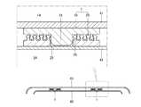
- the hook-and-loop fastener 1 of the first embodiment described aboveis used, for example, for joining two plates.
- these two platesare an outer plate 41 that forms the body side of the automobile, and an inner plate 42 that is fixed to the inner side of the outer plate 41.
- the outer plate 41 and the inner plate 42are fixed by a plurality of sets of hook-and-loop fasteners 1 of the first embodiment.
- one of the first and second hook-and-loop fastener members 10 and 20 (the first hook-and-loop fastener member 10 in the illustrated example) of each set of hook-and-loop fasteners 1is bonded or welded to the inner surface of the outer plate 41.
- the other one of the first and second hook-and-loop fastener members 10 and 20(second hook-and-loop fastener member 20 in the figure) is fixed to one surface of the inner plate 42 by bonding or welding.
- the fixing positions of the first and second hook-and-loop fastener members 10 and 20are set on the assumption that the inner plate 42 is fixed to the outer plate 41.
- each set of hook-and-loop fasteners 1cannot be seen from the inner surface side of the inner plate 42, but the protrusion 16 of the first hook-and-loop fastener member 10 is connected to the meshing element group 14. Therefore, the operator can fit the protrusion 16 to the guide 26 with a sense. Then, if the operator presses the inner plate 42 against the outer plate 41, the projection 16 is fitted in the hole 28 to accurately position the centers of the first and second hook-and-loop fastener members 10, 20, and the first The engaging element groups 14 and 24 of the second hook-and-loop fastener members 10 and 20 can be engaged with each other.
- the present inventionis not limited to the above-described embodiment, and can be changed as appropriate without departing from the spirit of the present invention.
- the hole portion 28is a through-hole in the above-described embodiment, but the present invention is not limited to this and may not penetrate.
- substrates 12 and 22was circular in the said embodiment, in this invention, not only this but shapes other than circular may be sufficient.
Landscapes
- Slide Fasteners, Snap Fasteners, And Hook Fasteners (AREA)
Abstract
Description
Translated fromJapanese本発明は面ファスナーに関する。The present invention relates to a hook-and-loop fastener.
面ファスナーは、連結および分離可能な一対の面ファスナー部材を備えるものである。面ファスナー部材は、通常、基板と、基板の厚み方向の一面から突出する多数の連結素子の集合である連結素子群とを備えるものである。また連結素子の一例として、キノコと類似する形状をしていることから、俗にキノコ型と称される連結素子が存在する。キノコ型の連結素子同士は、キノコ状の頭部が噛み合うようにして連結することから、以後、キノコ型の連結素子を「噛合素子」と称する。The hook-and-loop fastener includes a pair of hook-and-loop fastener members that can be connected and separated. A hook-and-loop fastener member is normally provided with a board | substrate and the connection element group which is a group of many connection elements which protrude from one surface of the thickness direction of a board | substrate. As an example of the connecting element, there is a connecting element commonly called a mushroom type because it has a shape similar to a mushroom. Since the mushroom-type coupling elements are coupled so that the mushroom-shaped heads mesh with each other, the mushroom-type coupling elements are hereinafter referred to as “meshing elements”.
そして噛合素子を備える面ファスナーの一例として、一対の面ファスナー部材同士を位置決めして連結できるように、基板と噛合素子群の他に、位置決め手段を備えるものが存在する(特許文献1,2)。And as an example of a hook_and_loop | surface fastener provided with a meshing element, what has a positioning means other than a board | substrate and a meshing element group exists so that a pair of surface fastener members can be positioned and connected (
特許文献1の図3に開示されている位置決め手段は、一方の面ファスナー部材には噛合素子群の中心部において基板の厚み方向の一面から突出する柱状突起を備え、他方の面ファスナー部材には噛合素子群の中心部であって基板の厚み方向の一面に柱状突起を抜き差し可能な孔を備えるものである。より詳しくは、柱状突起は、噛合素子群の中心部において噛合素子群よりも基板から突出するように形成されている。なお特許文献2の図3に開示されている位置決め手段は、特許文献1の図3に開示されている位置決め手段と比べて、少し形状が異なる程度であり、同じ構成要素を備えるものである。In the positioning means disclosed in FIG. 3 of
上記面ファスナー部材を用いて、一対の面ファスナー部材同士を連結するときには、1)まず孔の外周に配置された複数の噛合素子の内側に柱状突起を通過させ、2)次に柱状突起を孔に差し込むと共に、一対の面ファスナーの噛合素子同士を連結させる。When connecting a pair of hook-and-loop fastener members using the hook-and-loop fastener member, 1) first pass the columnar protrusions inside the plurality of meshing elements arranged on the outer periphery of the hole, and 2) then insert the columnar protrusions into the holes. And the meshing elements of the pair of hook-and-loop fasteners are connected to each other.
しかしながら特許文献1の図3に示された位置決め手段は、孔の直径に対して柱状突起の直径が非常に小さいので、孔の中心と柱状突起の中心とを一致させることは非常に困難であり、位置決め精度が悪い。However, since the positioning means shown in FIG. 3 of
また仮に位置決め手段が特許文献1の図3とは違って、孔の直径と柱状突起の直径を殆ど同じに設定すると、噛合素子同士が連結し難くなる。それは以下の理由による。
特許文献1の図3に示された面ファスナーでは、柱状突起の中心と孔の中心を一致させると、柱状突起の外周を最も近くで取り囲む複数の噛合素子(半径方向に関して最も内側に位置する複数の噛合素子)は、孔の外周を最も近くで取り囲む複数の噛合素子よりも半径方向内側に配置されている。つまり特許文献1の図3に示された面ファスナーの技術的思想は、柱状突起の外周を最も近くで取り囲む複数の噛合素子における半径方向内側に、孔側の噛合素子を収容する思想が無いものである。
噛合素子同士が連結するときは、噛合素子が基板側を中心にして瞬間的に倒れ、噛合素子が復元力によって元に戻ったり、戻ろうとして倒れた状態を保ったりして、噛合素子が噛み合うものである。したがって噛合素子が倒れる空間が必要となる。
それにも関わらず、位置決め手段が孔の直径と柱状突起の直径を殆ど同じに設定したものであると、柱状突起の外周を最も近くで取り囲む複数の噛合素子と柱状突起との間が非常に狭くなる。そうすると柱状突起の外周を最も近くで取り囲む複数の噛合素子は、倒れる空間が狭くなり、相手の面ファスナー部材の噛合素子に連結し難くなる。Also, if the positioning means is different from FIG. 3 of
In the hook-and-loop fastener shown in FIG. 3 of
When the meshing elements are connected to each other, the meshing element is momentarily tilted around the substrate side, and the meshing element meshes with the restoring element to return to its original state or keep the tilted state to return. Is. Therefore, a space where the meshing element falls is necessary.
Nevertheless, if the positioning means has the hole diameter and the columnar protrusion diameter almost the same, the space between the plurality of meshing elements and the columnar protrusion that surround the outer periphery of the columnar protrusion closest is very narrow. Become. As a result, the plurality of meshing elements that surround the outer periphery of the columnar protrusion closest to each other have a narrow space for falling, and are difficult to connect to the meshing elements of the mating surface fastener member.
本発明は上記実情を考慮して創作されたもので、その目的は、位置決め精度を向上させると共に、一対の面ファスナー部材を連結し易くすることである。The present invention was created in consideration of the above circumstances, and its purpose is to improve positioning accuracy and to easily connect a pair of hook-and-loop fastener members.
本発明の面ファスナーは、連結および分離可能な第1、第2の面ファスナー部材を備える。
第1、第2の面ファスナー部材は、柱状の柱部、柱部の先端から柱部の延長方向に対して交差する方向および前記延長方向に突出する頭部を備える噛合素子を同心円状に配列してある噛合素子群と、平板状をなすと共にその厚み方向の一面から噛合素子群の各柱部が突出する基板とをそれぞれ備える。
第1の面ファスナー部材は、噛合素子群の半径方向内側であって基板の前記一面の噛合素子群が配列する同心円の中心部から噛合素子群よりも突出する突起部と、噛合素子群のうち半径方向に関して最も内側に位置する複数の噛合素子と突起部とによって、それらの半径方向の間に形成される収容凹部とを備える。
第2の面ファスナー部材は、基板の前記一面の噛合素子群が配列する同心円の中心部において突起部の先部を収容する穴部を備え、噛合素子群のうち半径方向に関して最も内側に位置する複数の噛合素子を、突起部を穴部へ向かって移動可能に案内すると共に、収容凹部に収容される案内部として兼用する。The hook-and-loop fastener of the present invention includes first and second hook-and-loop fastener members that can be connected and separated.
The first and second hook-and-loop fastener members are arranged concentrically with columnar column portions, a direction intersecting with the extension direction of the column portion from the tip of the column portion, and a head protruding in the extension direction. Each engaging element group, and a substrate that has a flat plate shape and from which one column of the engaging element group protrudes from one surface in the thickness direction.
The first hook-and-loop fastener member is a radially inner side of the meshing element group, and a protrusion protruding from the meshing element group from the center part of the concentric circle where the meshing element group on the one surface of the substrate is arranged, and the meshing element group A housing recess formed between the plurality of meshing elements and the protrusions located on the innermost side in the radial direction is formed between the radial directions.
The second hook-and-loop fastener member includes a hole portion that accommodates the tip portion of the protruding portion at the center portion of the concentric circle where the meshing element groups on the one surface of the substrate are arranged, and is located on the innermost side in the radial direction among the meshing element groups. The plurality of meshing elements guide the protrusions so as to be movable toward the holes, and also serve as guides accommodated in the accommodating recesses.
突起部が穴部に収容されるものであれば、穴部の直径と突起部の直径との関係は問わず、たとえば穴部の直径は突起部の直径と同じであったり、突起部の直径よりも僅かに長かったりしても良い。しかし穴部に突起部を差し込みやすくし、しかも突起部の中心と穴部の中心をできるだけ一致させ、第1の面ファスナー部材と第2の面ファスナー部材との位置決め精度を向上させるには、それには次の1)、2)のようにすることが望ましい。As long as the protrusion is accommodated in the hole, the relationship between the diameter of the hole and the diameter of the protrusion does not matter. For example, the diameter of the hole is the same as the diameter of the protrusion, or the diameter of the protrusion It may be slightly longer than. However, in order to improve the positioning accuracy of the first surface fastener member and the second surface fastener member by making it easier to insert the protrusion into the hole and making the center of the protrusion and the center of the hole coincide as much as possible, It is desirable to perform the following 1) and 2).
1)穴部の直径は突起部の直径よりも長くすることである。また仮想の円であって第1の面ファスナー部材の噛合素子群のうち半径方向に関して最も内側に位置する複数の噛合素子における中心を通過する仮想の円の直径は、第2の面ファスナー部材の案内部における外接円の直径よりも大きいものとすることである。そのうえで穴部の直径と突起部の直径との差は、仮想の円の半径と案内部の外接円の半径との差よりも小さくすることである。1) The diameter of the hole is longer than the diameter of the protrusion. The diameter of the virtual circle that passes through the center of the plurality of meshing elements located on the innermost side in the radial direction among the meshing element group of the first surface fastener member is the diameter of the second surface fastener member. The diameter is larger than the diameter of the circumscribed circle in the guide portion. In addition, the difference between the diameter of the hole portion and the diameter of the projection portion is to be smaller than the difference between the radius of the virtual circle and the radius of the circumscribed circle of the guide portion.
2)穴部の直径は突起部の直径よりも長くすることである。そのうえで穴部の直径と突起部の直径との差は、第1又は第2の面ファスナー部材の柱部の直径よりも小さくすることである。2) The diameter of the hole is longer than the diameter of the protrusion. In addition, the difference between the diameter of the hole and the diameter of the protrusion is to be smaller than the diameter of the column portion of the first or second hook-and-loop fastener member.
案内部が突起部を案内するものであれば、案内部の直径と突起部の直径との関係は問わず、たとえば穴部の直径は突起部の直径と同じであったり、突起部の直径よりも僅かに長かったりしても良い。しかし案内部に突起部を差し込みやすくし、しかも突起部の中心と穴部の中心をできるだけ一致させ、第1の面ファスナー部材と第2の面ファスナー部材との位置決め精度を向上させるには、次のようにすることが望ましい。
案内部の内接円の直径は、突起部の直径よりも長くすることである。そのうえで案内部の内接円の直径と突起部の直径との差は、第1、第2の面ファスナー部材の柱部の直径よりも小さくすることである。If the guide part guides the protrusion part, the relationship between the diameter of the guide part and the diameter of the protrusion part does not matter. For example, the diameter of the hole part is the same as the diameter of the protrusion part or the diameter of the protrusion part. May be slightly longer. However, in order to improve the positioning accuracy of the first surface fastener member and the second surface fastener member by making it easy to insert the protrusion into the guide portion and making the center of the protrusion and the center of the hole coincide as much as possible, It is desirable to do as follows.
The diameter of the inscribed circle of the guide part is longer than the diameter of the protrusion part. In addition, the difference between the diameter of the inscribed circle of the guide portion and the diameter of the protrusion is to be smaller than the diameter of the column portion of the first and second hook-and-loop fastener members.
突起部の先端面が第2の面ファスナー部材における噛合素子群の中に入らないようにするためには次のようにすることが望ましい。
すなわち、突起部の先端面の直径は、第2の面ファスナー部材の中心部よりも半径方向外側の領域において隣り合う噛合素子同士の最短距離よりも長くすることである。In order to prevent the front end surface of the protrusion from entering the meshing element group in the second hook-and-loop fastener member, it is desirable to do the following.
That is, the diameter of the front end surface of the protrusion is set to be longer than the shortest distance between adjacent meshing elements in the region radially outward from the center portion of the second hook-and-loop fastener member.
本発明の面ファスナーによれば、第2の面ファスナー部材の噛合素子群のうち半径方向に関して最も内側に位置する複数の噛合素子が案内部として機能し、その案内部が突起部を穴部へ向かって移動可能に案内するので、突起部を第2の面ファスナー部材の穴部に挿入し易くなる。しかも第1の面ファスナー部材の噛合素子群のうち半径方向に関して最も内側の複数の噛合素子がその半径方向内側には収容凹部を介して突起部を備えるので、たとえば収容凹部のない従来のようなものに比べれば、半径方向内側に倒れることも可能となり、噛合素子同士が連結し易くなる。さらに案内部が収容凹部に収容されることによって、第1、第2の面ファスナー部材の位置決め精度が向上する。According to the surface fastener of the present invention, a plurality of meshing elements located on the innermost side in the radial direction among the meshing element groups of the second surface fastener member function as a guide portion, and the guide portion serves as a projection portion into the hole portion. Since it guides so that it can move toward, it becomes easy to insert a projection part in the hole of a 2nd surface fastener member. Moreover, since the plurality of innermost engaging elements in the radial direction among the engaging element groups of the first hook-and-loop fastener member are provided with protrusions via the receiving recesses on the inner side in the radial direction, Compared with a thing, it also becomes possible to fall inward in the radial direction, and the meshing elements are easily connected. Furthermore, the positioning accuracy of the first and second hook-and-loop fastener members is improved by the guide portion being housed in the housing recess.
また穴部の直径が突起部の直径よりも長く、仮想の円の直径が第2の面ファスナー部材の案内部における外接円の直径よりも大きく、且つ穴部の直径と突起部の直径との差が仮想の円の半径と案内部の外接円の半径との差よりも小さい面ファスナーであれば、穴部よりも突起部が僅かに小さいので、突起部が穴部に差し込みやすくなると共に、第1の面ファスナー部材と第2の面ファスナー部材との位置決め精度が向上する。The diameter of the hole is longer than the diameter of the protrusion, the diameter of the virtual circle is larger than the diameter of the circumscribed circle in the guide part of the second surface fastener member, and the diameter of the hole and the diameter of the protrusion If the surface fastener is smaller than the difference between the radius of the virtual circle and the radius of the circumscribed circle of the guide portion, the protrusion is slightly smaller than the hole, so that the protrusion can be easily inserted into the hole, Positioning accuracy between the first hook-and-loop fastener member and the second hook-and-loop fastener member is improved.
また穴部の直径が突起部の直径よりも長く、穴部の直径と突起部の直径との差が第1又は第2の面ファスナー部材の柱部の直径よりも小さい面ファスナーであれば、穴部よりも突起部が僅かに小さいので、突起部が穴部に差し込みやすくなると共に、第1の面ファスナー部材と第2の面ファスナー部材との位置決め精度が向上する。In addition, if the diameter of the hole is longer than the diameter of the protrusion, and the difference between the diameter of the hole and the diameter of the protrusion is smaller than the diameter of the column part of the first or second surface fastener member, Since the protruding portion is slightly smaller than the hole portion, the protruding portion can be easily inserted into the hole portion, and positioning accuracy between the first hook-and-loop fastener member and the second hook-and-loop fastener member is improved.
また案内部の内接円の直径が突起部の直径よりも長く、案内部の内接円の直径と突起部の直径との差が第1、第2の面ファスナー部材の柱部の直径よりも小さい面ファスナーであれば、案内部の内接円よりも突起部が僅かに小さいので、突起部が案内部に差し込みやすくなり、第1の面ファスナー部材と第2の面ファスナー部材との位置決め精度が向上する。Further, the diameter of the inscribed circle of the guide portion is longer than the diameter of the projection portion, and the difference between the diameter of the inscribed circle of the guide portion and the diameter of the projection portion is larger than the diameter of the column portion of the first and second hook-and-loop fastener members. If the surface fastener is smaller, the protrusion is slightly smaller than the inscribed circle of the guide portion, so that the protrusion can be easily inserted into the guide portion, and the first surface fastener member and the second surface fastener member are positioned. Accuracy is improved.
また突起部の先端面の直径が第2の面ファスナー部材の中心部よりも半径方向外側の領域において隣り合う噛合素子同士の最短距離よりも長い面ファスナーであれば、突起部の先端面が第2の面ファスナー部材における噛合素子群の中に入らなくなるので、第1、第2の面ファスナー部材を連結し易い。Further, if the surface fastener has a diameter that is longer than the shortest distance between adjacent meshing elements in a region radially outward from the center portion of the second surface fastener member, the tip end surface of the protrusion is the first surface of the protrusion. The first and second hook-and-loop fastener members can be easily connected because they do not enter the meshing element group of the two hook-and-loop fastener members.
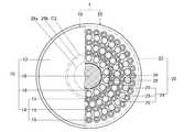
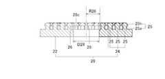
本発明の第一実施形態の面ファスナー1は図1に示すように、連結および分離可能な第1、第2の面ファスナー部材10,20を備えるものである。なお図1では、第1、第2の面ファスナー部材10,20を視覚的に区別し易くするために、第1の面ファスナー部材10を部分断面図で表している。また図1では、第1、第2の面ファスナー部材10,20の連結状態を視覚的に理解し易くするために、後述する噛合素子群14,24の位置を、少し不正確なものとしてある。噛合素子群14,24の正確な位置は、図2~6に示されている。The hook and
第1の面ファスナー部材10は樹脂製で、図3、4に示すように、基板12と、基板12の厚み方向の一面から突出する噛合素子群14とを備える。
第2の面ファスナー部材20も樹脂製で、図5、6に示すように、基板22と、基板22の厚み方向の一面から突出する噛合素子群24とを備える。The first hook-and-
The second hook-and-
第1、第2の面ファスナー部材10,20が連結する場合、各基板12,22の厚み方向の二面のうち噛合素子群14,24が突出する面は、相手方の面ファスナー部材10,20に対向する面なので、以後、「対向面」と称する。
このように基板12,22と噛合素子群14,24は、第1、第2の面ファスナー部材10,20において共通の構成部分であるので、以下では、第1の面ファスナー部材10の基板12と噛合素子群14を中心に説明する。第2の面ファスナー部材20の基板22と噛合素子群24は、第1の面ファスナー部材10の基板22と噛合素子群24と同じ部分については、説明をできる限り省略し、相違する部分については、説明を詳細にする。When the first and second hook-and-
Thus, since the board |
第1の面ファスナー部材10の基板12は図3、4に示すように、平板状をなすと共に円形である。また基板12は、噛合素子群14を配置するための基準点12cを説明の便宜上備えるもので、円形の中心が基準点12cである。The
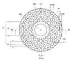
第2の面ファスナー部材20の基板22も図5、6に示すように、第1の面ファスナー部材10の基板12と同様に平板状をなすと共に外形が円形である。また基板22は、噛合素子群24を配置するための基準点22cを説明の便宜上備えるもので、円形の中心が基準点22cである。
なお図1の例では、第2の面ファスナー部材20の基板22の直径は、第1の面ファスナー部材10の基板12の直径よりも大きくしてあるが、逆に第2の面ファスナー部材20の基板22の直径よりも小さくても良いし、図2の例のように第2の面ファスナー部材20の基板22の直径と同じであっても良い。As shown in FIGS. 5 and 6, the
In the example of FIG. 1, the diameter of the
第1の面ファスナー部材10の噛合素子群14は図3、4に示すように、多数の噛合素子15の集合であり、基板12の中心部よりも半径方向外側に多数の噛合素子15を同心円状に配列したものである。図示の例では、全ての噛合素子15は、中心を共有し、半径の異なる4つの仮想の円の円周上に配列されている。説明の便宜上、半径方向に関して最も内側の円の円周上に配列された噛合素子15の集まりを第1集団と称し、残りの各円の円周上に配列された噛合素子15の集まりを、第1集団に対して半径方向に近い方から順に、第2、第3、第4集団と称する。As shown in FIGS. 3 and 4, the
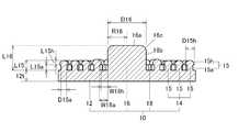
第1の面ファスナー部材10の全ての噛合素子15は同じ形態をしている。噛合素子15は、基板12の対向面からその厚み方向に突出する柱状(より詳しくは円柱状)の柱部15a、柱部15aの先端から柱部15aの延長方向に対して交差する方向および前記延長方向に突出する頭部15hを備えるものである。柱部15aの延長方向に対して交差する方向とは、本実施形態では、柱部15aが円柱状であるので、柱部15aの半径方向外側とも言える。噛合素子15は基板12側を中心にして倒れるように弾性変形可能なものである。また頭部15hは、図示の例では、半球状である。したがって図示の例では、頭部15hの直径D15hは、半球状の頂部側と基板12側とでは異なることになるが、ここでの頭部の直径D15hとは、最も長い直径のことであり、基板12側の部分(半球の底面の外周部分)の直径である。また頭部15hは、半球状の底面の中心部に柱部15aが配置されている。
また第1~第4の各集団を構成する複数の噛合素子15は、円周方向に等間隔あけて配列されている。また隣り合う2つの集団の半径方向の間隔は、いずれも均等にしてある。なお隣り合う2つの集団の半径方向の間隔は、頭部15h,15h同士よりも柱部15a,15a同士の方が広くなっている。ちなみに図3の例では、隣り合う2つの集団の半径方向の間隔のうち柱部15a,15a同士の間隔とは、半径方向内側の集団を構成する複数の噛合素子15の柱部15aの外接円C1と、半径方向外側の集団を構成する複数の噛合素子15の柱部15aの内接円C2との間隔W1であり、この間隔W1は、噛合素子15の柱部15aの直径D15aと同じ長さである。All the
The plurality of meshing
第2の面ファスナー部材20の噛合素子群24も図5、6に示すように多数の噛合素子25の集合であり、噛合素子25の配列以外、第1の面ファスナー部材10の噛合素子群14と同じである。
第2の面ファスナー部材20の噛合素子群24は、基板22の中心部よりも半径方向外側に多数の噛合素子25を同心円状に配列した点では、第1の面ファスナー部材10の噛合素子群14と同じである。また図示の例では、全ての噛合素子25は、中心を共有し、半径の異なる4つの仮想の円の円周上に配列されている。したがって第2の面ファスナー部材20の噛合素子群24も4つの集団より構成される。そして説明の便宜上、半径方向に関して最も内側の円の円周上に配列された噛合素子15の集まりを第1集団と称し、残りの各円の円周上に配列された噛合素子15の集まりを、第1集団から半径方向に近い方から順に、第2、第3、第4集団と称する。
また第2の面ファスナー部材20の噛合素子群24を構成する4つの集団は、第1の面ファスナー部材10の噛合素子群14を構成する4つの集団と比べて、たがいの基準点22c、12cに対する配列(距離)の点では、相違している。つまり第2の面ファスナー部材20の噛合素子群24と第1の面ファスナー部材10の噛合素子群14とが、互いの基準点12c、22cを一致させた状態で連結された状態を想定すると、第2の面ファスナー部材20の半径方向に隣り合う集団の間に、第1の面ファスナー部材10の一つの集団が配置される。より詳しく言えば第1の面ファスナー部材10の第4集団と第3集団の間に、第2の面ファスナー部材10の第4集団が配置される。また第2の面ファスナー部材20の第1集団は、第1の面ファスナー部材10の第1集団よりも半径方向内側(当該第1集団と後述の突起部16との間)に配列される。The meshing
The meshing
Further, the four groups constituting the meshing
第2の面ファスナー部材20の全ての噛合素子25は、第1の面ファスナー部材10の噛合素子15と同じ形態である。したがって噛合素子25は、柱部25a、頭部25hを備え、基板12側を中心にして倒れるように弾性変形可能なものである。All the
また第1、第2の面ファスナー部材10,20は、互いの基準点12c、22cを殆ど一致させた状態で連結するために、専用の構成部分をそれぞれ有する。The first and second hook-and-
第1の面ファスナー部材10は図3、4に示すように、基板12と噛合素子群14の他に、噛合素子群14の内側であって基板12の対向面の中心部から噛合素子群14よりも突出する突起部16と、噛合素子群14のうち第1集団(半径方向に関して最も内側の円周上に位置する複数の噛合素子15)と突起部16によって、それらの半径方向の間に形成される収容凹部18とを備える。As shown in FIGS. 3 and 4, the first hook-and-
突起部16は、基板12の対向面の中心部に基準点12cに対して同心状に形成されると共に、円柱状である。また突起部16は、先部の外周部、つまり先端面16aと側面16bとが交差する角部16cを面取りした形状である。より詳しくは角部16cは、基板12側から先端へ向かうにつれて徐々に直径を狭めるようにしてあるもので、図3の例では、その外面を円弧状に膨らむ曲面としてある。
突起部16の先端面16aは、基板12の対向面と平行な平面であって、円形状である。この突起部16の先端面16aは、第1、第2の面ファスナー部材10,20を連結するときに、第2の面ファスナー部材20の噛合素子群24の中に入らないようにするために、第2の面ファスナー部材20の中心部よりも半径方向外側の領域において隣り合う噛合素子25同士の最短距離よりも、長い円形状にしてある。より具体的には、第2の面ファスナー部材20の中心部よりも半径方向外側の領域において円周方向と半径方向に隣り合う3つまたは4つの噛合素子25で囲まれる間の領域よりも、大きな円形状にしてある。これにより第1、第2の面ファスナー部材を連結し易くなる。
なお突起部16の側面16bは、基準点12cに対して同心状の円筒面である。The
The
The
突起部16、噛合素子15、噛合素子群14は、基板12からの突出長さ(基板12の厚み方向に延長する長さであって、以下、「突出長さ」という。)を以下のようにしてある。
噛合素子15の突出長さL15は、図3,4の例では基板12の厚み12tよりも僅かに長くしてある。柱部15aの突出長さL15aは、頭部15hの突出長さL15hよりも長くしてある。なお、噛合素子15の突出長さL15とは、基板12の対向面から噛合素子15の突出方向先端までの長さであり、柱部15aの突出長さL15aとは、基板12の対向面から柱部15aと頭部15hの境界までの長さであり、頭部15hの突出長さL15hとは、柱部15aと頭部15hの境界から噛合素子15の突出方向先端までの長さである。また噛合素子群14の突出長さとは、全ての噛合素子15の中で、最も長い突出長さのことであり、本実施形態では、全ての噛合素子15が同じ突出長さであるので、噛合素子15の突出長さと同一である。
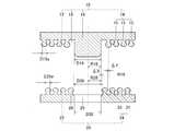
突起部16の突出長さL16は、噛合素子群14の基板12からの突出長さよりも長い。また突起部16の突出長さL16は、基板12の厚み12tと噛合素子15の突出長さL15を合わせた合計値以下であって、噛合素子15の突出長さL15の二倍以上にしてある。突起部16の突出長さL16とは、基板12の対向面から突起部16の突出方向の先端までの長さである。図示の例では、突起部16の突出長さL16は、噛合素子15の突出長さL15の二倍よりも長い。また、図7に示す通り、第1及び第2の面ファスナー部材の連結状態において、突起部16の先端面16aは、第2の面ファスナー部材の噛合素子25が突出する基板22の上面位置よりも下方に突出し、第2の面ファスナー部材の噛合素子25が突出する基板22の下面(基板22の上面とは反対側の面)の位置からは突出しない。The
The protrusion length L15 of the meshing
The protruding length L16 of the
収容凹部18は、突起部16の突出方向に開口する円筒状の空間部であり、その内周側は突起部16の外周面によって区画され、その外周側は、第1集団を構成する複数の噛合素子15によって、円周方向を等間隔おきに区画されると共に、円周方向に隣り合う噛合素子15,15の間を半径方向外側に開口している。The
収容凹部18は、半径方向の間隔、つまり突起部16と第1集団の噛合素子15の間隔に関して、以下のようになっている。突起部16と噛合素子15の頭部15hとの間隔W18hは、最も狭い部分では、柱部15aの直径よりも広く、頭部15hの直径よりも狭くなっている。また突起部16と噛合素子15の柱部15aとの間隔W18aは、柱部15aの直径D15aよりも広く、頭部15hの直径D15hよりも狭くしてある。したがって収容凹部18の内周面を形成する突起部16と、収容凹部18の外周面を形成する噛合素子15の柱部15aとの間には、第2の面ファスナー部材20の噛合素子25の頭部25hは寸法上では嵌ることができず、円周方向に隣り合う2つの噛合素子15,15と突起部16との間に、通常嵌る。The
第2の面ファスナー部材20は図5,6に示すように、基板22に突起部16の先部を収容する穴部28を備える。
穴部28は、基板22の対向面の中心部に基準点22cに対して同心状に形成されると共に、図示の例では基板22の厚み方向に貫通する穴である。穴部28の内面は、突起部16の形状に対応させた形状、より詳しくは突起部16のうち先部よりも基板12側の部分の形状に対応させた円筒面である。また穴部28は、その深さ方向のうち噛合素子群24側の端部、つまり基板22の対向面と穴部28の円筒面とが交差する角部28cを面取りした形状である。より詳しくは角部28cは、基板22の対向面側へ向かうにつれて徐々に直径を広げるようにしてあるもので、図示の例では、その内面を円弧状に膨らむ曲面としてある。
また穴部28の直径D28(角部28c以外の部分の直径)は図2に示すように、突起部16の直径D16(角部16c以外の部分の直径)よりも僅かに長い。より詳しくは、穴部28の直径D28と突起部の直径D16との差は、第1、第2の面ファスナー部材10,20の前記柱部15a、25aの直径D15a、D25aよりも小さい。As shown in FIGS. 5 and 6, the second hook-and-
The
Further, as shown in FIG. 2, the diameter D28 of the hole portion 28 (the diameter of the portion other than the
また第2の面ファスナー部材20の噛合素子群24は、第1の集団(半径方向に関して最も内側の円周上に位置する複数の噛合素子25)を、突起部16を穴部28へ向かって移動可能に案内すると共に収容凹部18に収容される案内部26として兼用する。
案内部26の内接円26aの半径R26は図2に示すように、突起部16の半径R16よりも僅かに大きい。そして案内部26の内接円26aの半径R26と突起部16の半径R16との差ΔXは、たとえば柱部15a,25aの直径D15a,D25a、より望ましくは柱部15a,25aの半径よりも小さい。したがって案内部26の内接円26aの直径D26は、突起部16の直径D16よりも僅かに長いものであり、案内部26の内接円26aの直径D26と突起部16の直径D16との差は、第1、第2の面ファスナー部材10,20の前記柱部15a、25aの直径D15a、D25aよりも小さい。
ちなみに案内部26の内接円26aとは図5に示すように、第1の集団を構成する全ての噛合素子25の頭部25hの半径方向内側に接する円である。いっぽう案内部26の外接円26bとは、第1の集団を構成する全ての噛合素子25の頭部25hの半径方向外側に接する円である。
また案内部26の外接円26bの直径は図3に示すように、仮想の円C3の直径であって、第1の面ファスナー部材10の収容凹部18の外周を形成する複数の噛合素子15、つまり第1集団を形成する全ての噛合素子15の中心(柱部15aの半径方向の中心)を通過する仮想の円C3の直径よりも、小さい。そして案内部26の内接円26aの半径R26と突起部16の半径R16との差ΔXは図2に示すように、仮想の円C3の半径と案内部26の外接円26bの半径との差ΔYと同じにしてある。また仮想の円C3の半径と案内部26の外接円26bの半径との差ΔYは、穴部28の直径D28と突起部16の直径D16との差よりも大きい。Further, the meshing
The radius R26 of the inscribed
Incidentally, the inscribed
Further, as shown in FIG. 3, the diameter of the circumscribed
案内部26の内接円26aの直径D26と突起部16の直径D16との差は、穴部28よりも半径方向外側において隣り合う噛合素子25,25の最短距離よりも小さい。図示の例では、隣り合う噛合素子25,25の最短距離とは、半径方向に隣り合う噛合素子25,25の頭部25h,25h同士の距離である。言い換えれば隣り合う集団のうち半径方向内側の集団における外接円と、半径方向外側の集団における内接円との半径方向の距離である。The difference between the diameter D26 of the inscribed
上記した第一実施形態の面ファスナー1は、以下の1)~6)のようにして連結する。
1)第1、第2の面ファスナー部材10,20を互いの基板12,22の厚み方向に間隔をあけて対向させる。
2)第1の面ファスナー部材10の突起部16と第2の面ファスナー部材20の穴部28に差し込むことを目的として、第1、第2の面ファスナー部材10,20を相対的に接近させる。
3)相対的に接近させたときに、第1、第2の面ファスナー部材10,20の互いの中心である基準点12c、22cが少しずれていると、突起部16の先端面16aが第2の面ファスナー部材20の案内部26の半径方向内側に嵌らず、突起部16の先端面16aが第2の面ファスナー部材20の噛合素子群24の頭部25hの表面に接触した不安定な状態となる。そしてこの不安定な状態を解消するために、第1、第2の面ファスナー部材10,20同士を相対的に突起部16の突出方向に直交する方向に動かして、第1、第2の面ファスナー部材10,20の互いの基準点12c、22cがほぼ一致すると、突起部16の先端面16aが案内部26の半径方向内側に案内され、突起部16の先部が案内部26の半径方向内側に入っていく。このとき、突起部16の角部16cを面取りした形状にしてあるので、突起部16が案内部26の半径方向内側に入り易くなる。また、案内部26を兼用する噛合素子25は、その頭部25hが半球状であるため、突起部16が案内部26の半径方向内側に入り易くなる。
4)さらに第1、第2の面ファスナー部材10,20を相対的に接近させると、突起部16の側面16bが案内部26の半径方向内側に案内され、突起部16の先端面16aが穴部28に接近する。
5)さらに第1、第2の面ファスナー部材10,20を相対的に接近させると、突起部16の角部16cと穴部28の角部28cとが互いに面取りした形状であることから、突起部16が穴部28の中に滑らかに案内され、突起部16が穴部28に少し入った後に、第1、第2の面ファスナー部材10,20の噛合素子15,25が頭部15h、25h同士で接触する。
6)さらに第1、第2の面ファスナー部材10,20を相対的に接近させると、噛合素子15,25が基板12,22側を中心にして瞬間的に倒れるように弾性変形し、第1の面ファスナー部材10の噛合素子15の頭部15hが、第2の面ファスナー部材20の噛合素子25の頭部25hを相対的に乗り越えて、復元力によって噛合素子15,25が元の形状に戻ろうとして、噛合素子群14,24同士が頭部15h,25hにおいて噛合する。またそれとほぼ同時に、穴部28に突起部16が深く嵌る。このようにして第1、第2の面ファスナー部材10,20が連結し、面ファスナー1が連結した状態となる。
なお連結した面ファスナー1に対して、第1、第2の面ファスナー部材10,20を互いの基板12,22の厚み方向に相対的に離隔させれば、噛合素子群14,24同士の噛合が解除され、第1、第2の面ファスナー部材10,20が分離する。しかもこれら基板12,22は平板状であるため、撓み易い。従って第1、第2の面ファスナー部材10,20を互いの基板12,22の厚み方向に相対的に離隔させた際には、基板12,22同士が撓むことによって噛合素子群14,24同士の噛合が解除され易くなり、第1、第2の面ファスナー部材10,20が分離し易い。The hook-and-
1) The first and second hook-and-
2) The first and second hook-and-
3) When the
4) When the first and second hook-and-
5) Further, when the first and second hook-and-
6) Further, when the first and second hook-and-
If the first and second hook-and-
上記した第一実施形態の面ファスナー1は上記した以外に、以下の効果を有する。
第2の面ファスナー部材20の噛合素子群24のうち第1の集団(半径方向に関して最も内側に位置する全ての噛合素子25)が案内部26として機能し、その案内部26が突起部16を穴部28へ向かって移動可能に案内するので、突起部を第2の面ファスナー部材の穴部に挿入し易くなる。In addition to the above, the hook-and-
Of the meshing
また案内部26の内接円26aの直径D26と突起部16の直径D16との差2ΔXは、第1、第2の面ファスナー部材10,20の柱部15a、25aの直径D15a、D25aよりも小さい。このように案内部26の内接円26aの直径D26が突起部16の直径D16よりも僅かに長いので、第1、第2の面ファスナー部材10,20の基準点12c、22cである中心同士が殆ど一致したまま、突起部16が穴部28の半径方向内側に案内され、突起部16を穴部28に差し込み易くなる。The difference 2ΔX between the diameter D26 of the inscribed
しかも第1の面ファスナー部材10の噛合素子群14のうち第1の集団は、その半径方向内側には収容凹部18を介して突起部16を備えるので、たとえば収容凹部18のない従来のようなものに比べれば、半径方向内側に倒れることも可能となり、噛合素子15,25同士が連結し易くなる。さらに案内部26が収容凹部18に収容されることによって、第1、第2の面ファスナー部材10,10は、半径方向の位置が定まることになり、互いの位置決め精度が向上する。Moreover, since the first group of the meshing
仮想の円C3の直径が第2の面ファスナー部材20の案内部26における外接円26bの直径よりも大きく、且つ穴部28の直径D28と突起部16の直径D16との差が仮想の円C3の半径と案内部26の外接円26bの半径との差よりも小さい。また穴部28の直径D28と突起部16の直径D16との差が第1、第2の面ファスナー部材10,20の柱部15a,25aの直径よりも小さい。このように穴部28の直径D28が突起部16の直径D16よりも僅かに大きいので、突起部16が穴部28に差し込みやすくなると共に、第1の面ファスナー部材10と第2の面ファスナー部材20との位置決め精度が向上する。The diameter of the virtual circle C3 is larger than the diameter of the circumscribed
上記した第一実施形態の面ファスナー1は、たとえば二枚の板を接合する用途に用いられる。これら二枚の板は、たとえば図7に示すように、自動車のボディ側を形成する外板41と、外板41の内側に固定される内板42である。この場合、外板41と内板42を複数組の第一実施形態の面ファスナー1で固定する。そして外板41の内面には各組の面ファスナー1における第1、第2の面ファスナー部材10,20のうち一方(図示の例では第1の面ファスナー部材10)を接着あるいは溶着等して固定し、内板42の一面には第1、第2の面ファスナー部材10,20のうち他方(図では第2の面ファスナー部材20)を接着あるいは溶着等して固定する。なお第1、第2の面ファスナー部材10,20の固定位置は、外板41に対して内板42を固定する位置を想定して、設定する。The hook-and-
外板41の内面側に内板42を配置すると、内板42の内面側からは各組の面ファスナー1が見えなくなるが、第1の面ファスナー部材10の突起部16が、噛合素子群14よりも突出しているので、作業者は感覚を頼りに、突起部16を案内部26に合わせることができる。そのうえで作業者は内板42を外板41に押し付けるようにすれば、突起部16を穴部28に嵌めて第1及び第2の面ファスナー部材10,20の中心を正確に位置決めし、第1、第2の面ファスナー部材10,20の噛合素子群14,24同士を噛合させることができる。When the
本発明は上記実施形態に限定されるものではなく、その趣旨を逸脱しない範囲において適宜変更可能である。例えば穴部28は上記実施形態では、貫通する穴であったが、本発明ではこれに限らず、貫通していなくても良い。また基板12,22の外形は、上記実施形態では、円形であったが、本発明ではこれに限らず、円形以外の形状であっても良い。The present invention is not limited to the above-described embodiment, and can be changed as appropriate without departing from the spirit of the present invention. For example, the
1 面ファスナー
10 第1の面ファスナー部材
12 基板
12c 基準点
12t 基板の厚み
14 噛合素子群
15 噛合素子
L15 噛合素子の突出長さ
L15a 柱部の突出長さ
L15h 頭部の突出長さ
C1 外接円
C2 内接円
W1 隣り合う外接円と内接円との間隔
15a 柱部
D15a 柱部の直径
15h 頭部
D15h 頭部の直径
16 突起部
L16 突起部の突出長さ
D16 突起部の直径
R16 突起部の半径
16a 先端面
16b 側面
16c 角部
18 収容凹部
W18a 収容凹部の間隔(突起部と噛合素子の頭部との間隔)
W18h 収容凹部の間隔(突起部と噛合素子の柱部との間隔)
C3 仮想の円
20 第2の面ファスナー部材
22 基板
22c 基準点
24 噛合素子群
25 噛合素子
25a 柱部
D25a 柱部の直径
25h 頭部
D25h 頭部の直径
26 案内部
D26 案内部の内接円の直径
R26 案内部の内接円の半径
26a 案内部の内接円
26b 案内部の外接円
ΔX 案内部の内接円の半径と突起部の半径との差
28 穴部
28c 角部
D28 穴部の直径
ΔY 仮想の円の半径と案内部の外接円の半径との差
41 外板
42 内板1 hook-and-
W18h Interval between receiving recesses (interval between projection and column of engaging element)
C3
Claims (5)
Translated fromJapanese前記第1、第2の面ファスナー部材(10,20)は、
柱状の柱部(15a,25a)、前記柱部(15a,25a)の先端から前記柱部(15a,25a)の延長方向に対して交差する方向および前記延長方向に突出する頭部(15h,25h)を備える噛合素子(15,25)を同心円状に配列してある噛合素子群(14,24)と、
平板状をなすと共にその厚み方向の一面から前記噛合素子群(14,24)の前記各柱部(15a,25a)が突出する基板(12,22)とをそれぞれ備え、
前記第1の面ファスナー部材(10)は、
前記噛合素子群(14)の半径方向内側であって前記基板(12)の前記一面の前記噛合素子群(14)が配列する同心円の中心部から前記噛合素子群(14)よりも突出する突起部(16)と、
前記噛合素子群(14)のうち半径方向に関して最も内側に位置する複数の前記噛合素子(15)と前記突起部(16)によって、それらの半径方向の間に形成される収容凹部(18)とを備え、
前記第2の面ファスナー部材(20)は、
前記基板(22)の前記一面の前記噛合素子群(24)が配列する同心円の中心部において前記突起部(16)の先部を収容する穴部(28)を備え、前記噛合素子群(24)のうち半径方向に関して最も内側に位置する複数の前記噛合素子(25)を、前記突起部(16)を前記穴部(28)へ向かって移動可能に案内すると共に、前記収容凹部(18)に収容される案内部(26)として兼用することを特徴とする面ファスナー。First and second hook-and-loop fastener members (10, 20) that can be connected and separated,
The first and second hook-and-loop fastener members (10, 20) are
Columnar column parts (15a, 25a), heads (15h, 25a) projecting in the direction intersecting with the extending direction of the column parts (15a, 25a) and the extending direction from the tips of the column parts (15a, 25a) A meshing element group (14, 24) in which meshing elements (15, 25) provided with 25h) are arranged concentrically;
Each having a flat plate shape and a substrate (12, 22) from which each column portion (15a, 25a) of the meshing element group (14, 24) protrudes from one surface in the thickness direction;
The first hook-and-loop fastener member (10)
A protrusion that protrudes more inward than the meshing element group (14) from a concentric center portion where the meshing element group (14) on the one surface of the substrate (12) is arranged on the radially inner side of the meshing element group (14). Part (16),
An accommodating recess (18) formed between the plurality of meshing elements (15) and the projections (16) located in the innermost side in the radial direction in the meshing element group (14) With
The second hook-and-loop fastener member (20)
A hole (28) for receiving the tip of the protrusion (16) at the center of a concentric circle in which the meshing element group (24) on the one surface of the substrate (22) is arranged; and the meshing element group (24 ) Of the plurality of meshing elements (25) located on the innermost side in the radial direction are guided so that the protrusion (16) can move toward the hole (28), and the receiving recess (18) A hook-and-loop fastener that is also used as a guide portion (26) to be accommodated in the bag.
仮想の円(C3)であって前記第1の面ファスナー部材(10)の前記噛合素子群(14)のうち半径方向に関して最も内側に位置する複数の前記噛合素子(15)における中心を通過する前記仮想の円(C3)の直径は、前記第2の面ファスナー部材(20)の前記案内部(26)における外接円(26b)の直径よりも大きいものであり、
前記穴部(28)の直径(D28)と前記突起部(16)の直径(D16)との差は、前記仮想の円(C3)の半径と前記案内部(26)の外接円(26b)の半径との差(ΔY)よりも小さいことを特徴とする請求項1に記載の面ファスナー。The diameter (D28) of the hole (28) is longer than the diameter (D16) of the protrusion (16),
An imaginary circle (C3) that passes through the center of the plurality of meshing elements (15) located on the innermost side in the radial direction in the meshing element group (14) of the first hook-and-loop fastener member (10). The diameter of the virtual circle (C3) is larger than the diameter of the circumscribed circle (26b) in the guide portion (26) of the second hook-and-loop fastener member (20),
The difference between the diameter (D28) of the hole (28) and the diameter (D16) of the protrusion (16) is the radius of the virtual circle (C3) and the circumscribed circle (26b) of the guide part (26). The hook-and-loop fastener according to claim 1, wherein the surface fastener is smaller than a difference (ΔY) from a radius of the hook.
前記穴部(28)の直径(D28)と前記突起部(16)の直径(D16)との差は、前記第1又は第2の面ファスナー部材(10,20)の前記柱部(15a、25a)の直径(D15a、D25a)よりも小さいことを特徴とする請求項1に記載の面ファスナー。The diameter (D28) of the hole (28) is longer than the diameter (D16) of the protrusion (16),
The difference between the diameter (D28) of the hole (28) and the diameter (D16) of the protrusion (16) is the difference between the pillar portion (15a, 2) of the first or second hook-and-loop fastener member (10, 20). The hook-and-loop fastener according to claim 1, wherein the hook-and-loop fastener is smaller than a diameter (D15a, D25a) of 25a).
前記案内部(26)の内接円(26a)の直径(D26)と前記突起部(16)の直径(D16)との差は、前記第1、第2の面ファスナー部材(10,20)の前記柱部(15a、25a)の直径(D15a、D25a)よりも小さいことを特徴とする請求項1に記載の面ファスナー。The diameter (D26) of the inscribed circle (26a) of the guide part (26) is longer than the diameter (D16) of the protrusion (16),
The difference between the diameter (D26) of the inscribed circle (26a) of the guide portion (26) and the diameter (D16) of the protrusion (16) is the first and second hook-and-loop fastener members (10, 20). The hook-and-loop fastener according to claim 1, wherein the surface fastener is smaller than the diameter (D15a, D25a) of the column part (15a, 25a).
Priority Applications (2)
| Application Number | Priority Date | Filing Date | Title |
|---|---|---|---|
| JP2018556099AJP6667009B2 (en) | 2016-12-14 | 2016-12-14 | Hook-and-loop fastener |
| PCT/JP2016/087273WO2018109877A1 (en) | 2016-12-14 | 2016-12-14 | Surface fastener |
Applications Claiming Priority (1)
| Application Number | Priority Date | Filing Date | Title |
|---|---|---|---|
| PCT/JP2016/087273WO2018109877A1 (en) | 2016-12-14 | 2016-12-14 | Surface fastener |
Publications (1)
| Publication Number | Publication Date |
|---|---|
| WO2018109877A1true WO2018109877A1 (en) | 2018-06-21 |
Family
ID=62558241
Family Applications (1)
| Application Number | Title | Priority Date | Filing Date |
|---|---|---|---|
| PCT/JP2016/087273CeasedWO2018109877A1 (en) | 2016-12-14 | 2016-12-14 | Surface fastener |
Country Status (2)
| Country | Link |
|---|---|
| JP (1) | JP6667009B2 (en) |
| WO (1) | WO2018109877A1 (en) |
Cited By (1)
| Publication number | Priority date | Publication date | Assignee | Title |
|---|---|---|---|---|
| CN113545102A (en)* | 2019-03-08 | 2021-10-22 | 大金工业株式会社 | Pore forming member, air permeable member, and air permeable cover |
Citations (5)
| Publication number | Priority date | Publication date | Assignee | Title |
|---|---|---|---|---|
| JPS62150907U (en)* | 1986-03-19 | 1987-09-24 | ||
| JPH08112113A (en)* | 1994-10-04 | 1996-05-07 | Minnesota Mining & Mfg Co <3M> | Opposite surface fastening zipping member and zipper with said zipping member |
| JP3636735B2 (en)* | 1993-08-03 | 2005-04-06 | ミネソタ マイニング アンド マニュファクチャリング カンパニー | Face-to-face engaging fastener member and fastener having the fastener member |
| WO2011086989A1 (en)* | 2010-01-14 | 2011-07-21 | 国立大学法人横浜国立大学 | Microfastener, microfastener production method, and microfastening element |
| US20140103567A1 (en)* | 2012-10-15 | 2014-04-17 | Velcro Industries B.V. | Touch fastening |
Family Cites Families (1)
| Publication number | Priority date | Publication date | Assignee | Title |
|---|---|---|---|---|
| US20130318752A1 (en)* | 2012-05-31 | 2013-12-05 | Velcro Industries B.V. | Releasable fastenings with barriers |
- 2016
- 2016-12-14WOPCT/JP2016/087273patent/WO2018109877A1/ennot_activeCeased
- 2016-12-14JPJP2018556099Apatent/JP6667009B2/enactiveActive
Patent Citations (5)
| Publication number | Priority date | Publication date | Assignee | Title |
|---|---|---|---|---|
| JPS62150907U (en)* | 1986-03-19 | 1987-09-24 | ||
| JP3636735B2 (en)* | 1993-08-03 | 2005-04-06 | ミネソタ マイニング アンド マニュファクチャリング カンパニー | Face-to-face engaging fastener member and fastener having the fastener member |
| JPH08112113A (en)* | 1994-10-04 | 1996-05-07 | Minnesota Mining & Mfg Co <3M> | Opposite surface fastening zipping member and zipper with said zipping member |
| WO2011086989A1 (en)* | 2010-01-14 | 2011-07-21 | 国立大学法人横浜国立大学 | Microfastener, microfastener production method, and microfastening element |
| US20140103567A1 (en)* | 2012-10-15 | 2014-04-17 | Velcro Industries B.V. | Touch fastening |
Cited By (1)
| Publication number | Priority date | Publication date | Assignee | Title |
|---|---|---|---|---|
| CN113545102A (en)* | 2019-03-08 | 2021-10-22 | 大金工业株式会社 | Pore forming member, air permeable member, and air permeable cover |
Also Published As
| Publication number | Publication date |
|---|---|
| JP6667009B2 (en) | 2020-03-18 |
| JPWO2018109877A1 (en) | 2019-06-24 |
Similar Documents
| Publication | Publication Date | Title |
|---|---|---|
| JP5506775B2 (en) | Snap button | |
| EP2600013B1 (en) | Grommet | |
| JP6446536B2 (en) | Check valve and disc | |
| JP5465218B2 (en) | fastener | |
| CN106567875A (en) | Multiple fixing element | |
| KR101599347B1 (en) | Assembly block | |
| CN112211885A (en) | positioning structure | |
| WO2018109877A1 (en) | Surface fastener | |
| US9917398B1 (en) | Mechanical snap connector assembly | |
| CN201739720U (en) | Supporting device and display with the supporting device | |
| US10569644B2 (en) | Mounting structure for integrated component of fuel tank | |
| CN109475880B (en) | Rotor installation structure and centrifugal separator | |
| JP6043197B2 (en) | Multi-point buckle | |
| JP2017096449A (en) | clip | |
| JP3215771U (en) | buckle | |
| JP4725999B2 (en) | Joint | |
| JP2013256251A (en) | Fastener | |
| JP6703028B2 (en) | Mounting structure and clip | |
| JP6115376B2 (en) | Panel fixing structure and automatic transaction device | |
| CN110023634A (en) | Closure member | |
| JP2012246942A (en) | Assembling device | |
| TWI755274B (en) | Tool holder | |
| JP2007120679A (en) | Plate material joint structure | |
| TWM562899U (en) | Rivet and riveting structure thereof | |
| JP5992017B2 (en) | Binding tool |
Legal Events
| Date | Code | Title | Description |
|---|---|---|---|
| 121 | Ep: the epo has been informed by wipo that ep was designated in this application | Ref document number:16923902 Country of ref document:EP Kind code of ref document:A1 | |
| ENP | Entry into the national phase | Ref document number:2018556099 Country of ref document:JP Kind code of ref document:A | |
| NENP | Non-entry into the national phase | Ref country code:DE | |
| 122 | Ep: pct application non-entry in european phase | Ref document number:16923902 Country of ref document:EP Kind code of ref document:A1 |