WO2018096864A1 - Portable measuring instrument - Google Patents
Portable measuring instrumentDownload PDFInfo
- Publication number
- WO2018096864A1 WO2018096864A1PCT/JP2017/038390JP2017038390WWO2018096864A1WO 2018096864 A1WO2018096864 A1WO 2018096864A1JP 2017038390 WJP2017038390 WJP 2017038390WWO 2018096864 A1WO2018096864 A1WO 2018096864A1
- Authority
- WO
- WIPO (PCT)
- Prior art keywords
- skin
- unit
- contact
- elastic
- contact member
- Prior art date
- Legal status (The legal status is an assumption and is not a legal conclusion. Google has not performed a legal analysis and makes no representation as to the accuracy of the status listed.)
- Ceased
Links
Images


Classifications
- A—HUMAN NECESSITIES
- A61—MEDICAL OR VETERINARY SCIENCE; HYGIENE
- A61B—DIAGNOSIS; SURGERY; IDENTIFICATION
- A61B5/00—Measuring for diagnostic purposes; Identification of persons
- A61B5/44—Detecting, measuring or recording for evaluating the integumentary system, e.g. skin, hair or nails
- A61B5/441—Skin evaluation, e.g. for skin disorder diagnosis
- A61B5/443—Evaluating skin constituents, e.g. elastin, melanin, water
- A—HUMAN NECESSITIES
- A61—MEDICAL OR VETERINARY SCIENCE; HYGIENE
- A61B—DIAGNOSIS; SURGERY; IDENTIFICATION
- A61B5/00—Measuring for diagnostic purposes; Identification of persons
- A—HUMAN NECESSITIES
- A61—MEDICAL OR VETERINARY SCIENCE; HYGIENE
- A61B—DIAGNOSIS; SURGERY; IDENTIFICATION
- A61B5/00—Measuring for diagnostic purposes; Identification of persons
- A61B5/0059—Measuring for diagnostic purposes; Identification of persons using light, e.g. diagnosis by transillumination, diascopy, fluorescence
- A61B5/0071—Measuring for diagnostic purposes; Identification of persons using light, e.g. diagnosis by transillumination, diascopy, fluorescence by measuring fluorescence emission
- A—HUMAN NECESSITIES
- A61—MEDICAL OR VETERINARY SCIENCE; HYGIENE
- A61B—DIAGNOSIS; SURGERY; IDENTIFICATION
- A61B5/00—Measuring for diagnostic purposes; Identification of persons
- A61B5/44—Detecting, measuring or recording for evaluating the integumentary system, e.g. skin, hair or nails
- A61B5/441—Skin evaluation, e.g. for skin disorder diagnosis
- A61B5/442—Evaluating skin mechanical properties, e.g. elasticity, hardness, texture, wrinkle assessment
- A—HUMAN NECESSITIES
- A61—MEDICAL OR VETERINARY SCIENCE; HYGIENE
- A61B—DIAGNOSIS; SURGERY; IDENTIFICATION
- A61B5/00—Measuring for diagnostic purposes; Identification of persons
- A61B5/74—Details of notification to user or communication with user or patient; User input means
- A61B5/742—Details of notification to user or communication with user or patient; User input means using visual displays
- G—PHYSICS
- G01—MEASURING; TESTING
- G01N—INVESTIGATING OR ANALYSING MATERIALS BY DETERMINING THEIR CHEMICAL OR PHYSICAL PROPERTIES
- G01N21/00—Investigating or analysing materials by the use of optical means, i.e. using sub-millimetre waves, infrared, visible or ultraviolet light
- G01N21/62—Systems in which the material investigated is excited whereby it emits light or causes a change in wavelength of the incident light
- G01N21/63—Systems in which the material investigated is excited whereby it emits light or causes a change in wavelength of the incident light optically excited
- G01N21/64—Fluorescence; Phosphorescence
- A—HUMAN NECESSITIES
- A61—MEDICAL OR VETERINARY SCIENCE; HYGIENE
- A61B—DIAGNOSIS; SURGERY; IDENTIFICATION
- A61B2562/00—Details of sensors; Constructional details of sensor housings or probes; Accessories for sensors
- A61B2562/02—Details of sensors specially adapted for in-vivo measurements
- A61B2562/0247—Pressure sensors
Definitions
- the present inventionrelates to a portable measuring instrument that measures the amount of accumulated fluorescent substance in the skin and the elastic modulus of the skin.
- AGEsare substances produced by glycation of proteins and are considered to be causative substances that promote aging. AGEs are fluorescent substances and emit fluorescence having a wavelength of 440 nm when irradiated with excitation light having a wavelength of 370 nm. A measuring instrument for measuring AGEs (terminal glycation products) using such properties of AGEs is conventionally known.
- This type of measuring deviceis based on an irradiation unit that irradiates excitation light, a light receiving unit that receives fluorescence generated from AGEs accumulated in the skin irradiated with excitation light, and the intensity of the received fluorescence. The accumulated amount of AGEs is measured.
- this type of measuring deviceis a relatively large device having a pedestal on which an arm or a hand is placed, and a measurement location is fixed to, for example, an arm or a finger. The measurement is performed by irradiating the arm or finger with excitation light while the arm or hand is placed on the pedestal.
- Patent Document 1discloses an apparatus having a measurement head having an irradiation unit and a light receiving unit and an operation box electrically connected to the measurement head as an example of such an AGEs measuring instrument.
- the measurement locationIn conventional AGEs measuring instruments, the measurement location is fixed to the arm or finger, and for example, it is difficult to measure the accumulated amount of AGEs in the skin of the face. On the other hand, in the measuring instrument described in Patent Document 1, since the measuring head is separated from the operation box, the measurement location is not fixed, but it is inconvenient to use while carrying the measuring instrument.
- the present inventionhas been made in view of the above-described circumstances, and an object thereof is to provide a portable measuring instrument while enabling measurement of the accumulated amount of fluorescent substances accumulated in the skin. It is in.
- the portable measuring instrumentincludes an accumulation amount measuring unit that measures the accumulation amount of the fluorescent substance accumulated in the skin per unit area, and a display unit that displays the measured accumulation amount. And a housing that accommodates or supports the accumulation amount measurement unit and the display unit and is gripped by a user, and the accumulation amount measurement unit irradiates excitation light toward the skin.
- a light receiving unitthat receives fluorescence generated from the fluorescent substance in the skin irradiated with the excitation light, detects the intensity of the received fluorescence, and based on the detected intensity, An accumulation amount calculation unit for calculating the accumulation amount of the fluorescent substance.
- the accumulation amount measuring unit for measuring the accumulation amount of the fluorescent substanceis housed or supported in the housing held by the user. Therefore, the portable measuring device having the above-described configuration is portable while enabling measurement of the accumulated amount of the fluorescent substance accumulated in the skin.
- the portable measuring devicefurther includes an elastic coefficient measuring unit that measures an elastic coefficient of the skin
- the display unitdisplays the measured elastic coefficient
- the housingincludes The elastic modulus measuring unit is housed or supported, and the housing includes a contact member that makes contact with the skin, and the elastic coefficient measuring unit is applied from the skin to the contact member.
- An elastic coefficient calculation unitfor calculating the elastic coefficient of the skin.
- the accumulated amount measuring unit that measures the accumulated amount of the fluorescent substance and the elastic coefficient measuring unit that measures the elastic coefficient of the skin corresponding to the elasticity of the skinare supported by the same casing. .
- the portable measuring instrument having the above-described configurationis portable while allowing both the measurement of the accumulated amount of the fluorescent substance accumulated in the skin and the measurement of the elasticity of the skin.
- the casingincludes a gripping member that movably supports the contact member and is gripped by a user, and an elastic member that connects the contact member and the grip member.
- the gripping memberincludes a contact surface that is brought into contact with the skin
- the deformation amount sensorincludes the elastic member when the contact member is in contact with the skin and the contact surface is in contact with the skin. The amount of deformation is calculated based on the contact pressure and the elastic constant of the elastic member, and the contact member protrudes from the contact surface when the contact member is not in contact with the skin.
- a deformation amount calculation unitthat calculates the deformation amount of the skin by subtracting the deformation amount of the elastic member from a distance.
- the deformation amount of the skinis such that the contact member and the contact surface come into contact with the skin from the protruding distance that the contact member protrudes from the contact surface when the contact member is not in contact with the skin. It is calculated by subtracting the amount of deformation of the elastic member when it is. Since the amount of skin deformation is detected without using a sensor that directly detects the amount of skin deformation, the cost required for the sensor is reduced.
- the contact memberhouses the irradiation part and the light receiving part, and the contact pressure sensor is fixed to the contact member.
- the irradiation unit and the light receiving unitare housed in the contact member, and the contact pressure sensor is fixed to the contact member. Therefore, when the contact member comes into contact with the skin, the irradiation unit can irradiate the skin with excitation light, the light receiving unit can receive fluorescence, and the contact pressure sensor can detect the contact pressure.
- the gripping memberincludes a probe portion that movably supports the contact member, and a main body portion to which the probe portion is detachable, and the probe portion includes the elastic member.
- the main body unithouses the accumulation amount calculation unit, the deformation amount calculation unit, and the elastic coefficient calculation unit.
- the display unit, the accumulation amount calculation unit, the deformation amount calculation unit, and the elastic coefficient calculation unitare stored in the main body unit, the elastic member is stored in the probe unit, and the contact member supported by the probe unit.
- the irradiation unit and the light receiving unitare housed in the contact pressure sensor. Since the probe unit is detachable from the main body unit, the irradiation unit, the light receiving unit, and the contact pressure sensor can be easily replaced.
- the irradiation unitis an ultraviolet LED that emits the excitation light having a peak wavelength of 370 nm.
- the excitation light having a peak wavelength of 370 nmis irradiated, the accumulated amount of AGEs that emit fluorescence of 440 nm with respect to the excitation light having a wavelength of 370 nm is efficiently measured.
- the portable measuring instrumentis portable while allowing both the measurement of the accumulated amount of the fluorescent substance accumulated in the skin and the measurement of the elasticity of the skin.
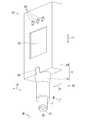
- FIG. 1is a perspective view showing the external appearance of the portable measuring instrument 10.
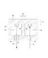
- FIG. 2is a perspective view showing the portable measuring instrument 10 in a state where the probe unit 13 is detached from the main body unit 14.
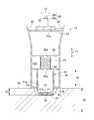
- FIG. 3is a cross-sectional view taken along the line III-III in FIG. 2 showing the contact member 11 and the probe portion 13 when not measured.
- FIG. 4is a cross-sectional view schematically showing the sensor chip 26.
- FIG. 5is a cross-sectional view showing the contact member 11 and the probe unit 13 at the time of measurement.
- FIG. 6is a block diagram showing an electrical configuration of the portable measuring instrument 10.
- the portable measuring instrument 10is a device that measures the accumulated amount of the fluorescent substance in the skin 30 per unit area and the elastic coefficient of the skin 30.
- the fluorescent substance to be measuredis AGEs (terminal glycation products).
- the accumulated amount of AGEsis measured by irradiating the AGEs in the skin 30 with the excitation light 15 to generate fluorescence 16 from the AGEs and detecting the intensity of the generated fluorescence 16.
- the elastic coefficient of the skin 30is measured by detecting the dent amount and the contact pressure of the skin 30 when a contact member 11 described later is brought into contact with the skin 30.
- the portable measuring instrument 10includes a housing 20.
- the housing 20includes a contact member 11 that makes contact with the skin 30 and a grip member 12 that is gripped by a user.
- the gripping member 12includes a probe portion 13 that supports the contact member 11 so as to be movable, and a main body portion 14 to which the probe portion 13 is detachable.
- the direction in which the contact member 11 and the gripping member 12 are arrangedis defined as the central axis direction 17 of the portable measuring instrument 10.
- the side where the contact member 11 is locatedis the front end side
- the side where the gripping member 12 is locatedis the rear end side.
- the first radial direction 18 and the second radial direction 19are orthogonal to each other and are orthogonal to the central axis direction 17.
- the first radial direction 18is a direction in which a display surface of a display unit 62 described later housed in the gripping member 12 faces.
- the contact member 11is a hollow container whose outer shape is a columnar shape.
- the contact member 11includes a disk-shaped front end wall 41, a disk-shaped rear end wall 42, and a cylindrical side wall 43.
- the front end wall 41 and the rear end wall 42are arranged along the central axis direction 17.
- the side wall 43connects the front end wall 41 and the rear end wall 42 along the central axis direction 17.
- An opening 41ais formed at the center of the tip wall 41, and the sensor chip 26 is disposed in the opening 41a.
- the sensor chip 26is fixed to the substrate 27, and the substrate 27 is fixed to the tip wall 41.
- a contact pressure sensor 24is fixed to the distal end surface of the distal end wall 41.
- an opening 42a through which a wiring such as a signal line passesis formed.
- the outer peripheral portion of the rear end wall 42is a flange portion 42 b that protrudes outward from the side wall 43 in the first radial direction 18 and the second radial direction 19.
- the sensor chip 26includes an ultraviolet LED (an example of an irradiation unit) 31, a photodiode (an example of a light receiving unit) 32, and a package 33 that houses the ultraviolet LED 31 and the photodiode 32. Yes.
- the package 33has a substantially rectangular parallelepiped shape with a hollow inside.
- the package 33includes a light emitting space 34 in which the ultraviolet LED 31 is disposed and a light receiving space 35 in which the photodiode 32 is disposed.
- the package 33includes a through hole 36 that allows the light emitting space 34 to communicate with the outside, a silicon microlens 37 that is disposed in the through hole 36, and a through hole 38 that allows the light receiving space 35 to communicate with the outside.
- the ultraviolet LED 31is a device that irradiates the excitation light 15 toward the skin 30.
- AGEsare fluorescent substances that generate fluorescence 440 nm when irradiated with excitation light 15 having a wavelength of 370 nm. Therefore, the ultraviolet LED 31 is configured to emit the excitation light 15 having a peak wavelength of 370 nm so that the fluorescence 16 corresponding to AGEs can be obtained.
- the ultraviolet LED 31only needs to be able to emit the excitation light 15 in a wavelength region including 370 nm, and is not limited to the case where the peak wavelength of the excitation light 15 is 370 nm.
- the excitation light 15 radiated from the ultraviolet LED 31is output to the outside of the package 33 through the silicon microlens 37 and is applied to the skin 30 at a position facing the contact member 11.
- fluorescence 16is generated from the AGEs.
- the photodiode 32is a device that receives the fluorescence 16 generated from the AGEs in the skin 30 irradiated with the excitation light 15 and detects the intensity of the received fluorescence 16. Based on the intensity of the detected fluorescence 16, the accumulated amount of AGEs in the skin 30 per unit area is measured.
- the sensor chip 26 or the substrate 27may include an amplifier circuit that amplifies the electrical signal output from the photodiode 32.
- the contact pressure sensor 24is a device that detects the contact pressure applied from the skin 30 to the contact member 11.
- the contact pressure sensor 24provided on the distal end surface of the contact member 11 contacts the skin 30.
- the contact pressure sensor 24is composed of, for example, a piezo element, and the pressure applied to the contact pressure sensor 24 is output as an electrical signal.
- the probe portion 13is a hollow container whose outer shape is generally cylindrical.
- the probe unit 13includes an annular tip wall 51, a disk-shaped intermediate wall 52, a disk-shaped rear wall 53, a cylindrical side wall 54, and an annular engagement convex portion 55.
- the tip wall 51, the intermediate wall 52, and the rear wall 53are arranged along the central axis direction 17.
- the side wall 54connects the front end wall 51, the intermediate wall 52, the rear wall 53, and the engagement convex portion 55 along the central axis direction 17.
- An opening 51 ais formed at the center of the tip wall 51.
- a side wall 43 of the contact member 11is disposed in the opening 51a.
- the inner diameter of the opening 51asubstantially matches the outer shape of the side wall 43, and is smaller than the outer diameter of the flange portion 42b. Therefore, the contact member 11 is supported without falling off the probe portion 13.
- the distal end surface of the distal end wall 51is a contact surface 51 b that is brought into contact with the skin 30.
- an opening 52a through which a wiring such as a signal line passesis formed in the center of the intermediate wall 52.
- an opening 53 a through which a wiring such as a signal line passesis formed at the center of the rear wall 53.
- the probe portion 13includes two engaging portions 58.
- the two engaging portions 58are arranged along the first radial direction 18 and are fixed to the side wall 54.
- the engaging portion 58has an extending portion 58a extending to the rear end side, and an engaging piece 58b extending radially inward from the rear end of the extending portion 58a.
- the engaging portion 58can be engaged with an engaged portion 46 described later provided in the main body portion 14.
- the engagement convex portion 55 of the probe portion 13can be engaged with an engagement concave portion 45 described later provided in the main body portion 14. In a state where the probe portion 13 is attached to the main body portion 14, the engaging portion 58 and the engaging convex portion 55 of the probe portion 13 engage with the engaged portion 46 and the engaging concave portion 45 of the main body portion 14.
- the portable measuring instrument 10includes a connector 56 in the probe unit 13.
- the connector 56is located on the rear end side of the rear wall 53 and is fixed to the rear wall 53.
- the connector 56can be electrically connected to a connector 64 described later provided on the main body 14. Signal lines from the ultraviolet LED 31, the photodiode 32, and the contact pressure sensor 24 are connected to the connector 56.
- the portable measuring instrument 10includes an elastic member 23 in the probe unit 13.
- the elastic member 23connects the contact member 11 and the probe portion 13 which is a part of the gripping member 12.
- the elastic member 23is a compression coil spring.
- the elastic member 23is in contact with the rear end wall 42 of the contact member 11 and the intermediate wall 52 of the probe portion 13.
- the contact member 11protrudes to the maximum from the probe portion 13, that is, the flange portion 42 b is in contact with the distal end wall 51 of the probe portion 13.
- the protruding distance 81is a distance from the contact surface 51 b to the distal end surface of the contact member 11 when the contact member 11 protrudes from the probe portion 13 to the maximum extent.
- the elastic member 23In the state where the contact member 11 protrudes from the probe portion 13 to the maximum extent, the elastic member 23 is in a compressed state. Therefore, the elastic member 23 always urges the contact member 11 toward the distal end side.
- the contact member 11is pressed against the skin 30 until the contact surface 51 b contacts the skin 30. At this time, the skin 30 is recessed by the contact member 11, and the contact member 11 is pushed toward the rear end side against the urging force of the elastic member 23.
- the elastic coefficient of the skin 30is an elastic coefficient when the skin 30 is considered to be an elastic body.
- the elastic coefficient of the skin 30is specified by the external force applied to the skin 30 when the skin 30 is depressed and the deformation amount (dent amount) 82 of the skin 30 at that time, using Hooke's law.
- the external force applied to the skin 30is equal to the force applied from the skin 30 to the contact member 11.
- This forceis specified based on the contact pressure applied from the skin 30 to the contact member 11.
- the deformation amount 82 of the skin 30is equal to the distance obtained by subtracting the deformation amount (shrinkage amount) 83 of the elastic member 23 from the protruding distance 81.
- the deformation amount 83 of the elastic member 23is specified based on the elastic coefficient of the elastic member 23 and the force applied to the abutting member 11 using the Hooke's law. Since the elastic coefficient of the elastic member 23 is specified in advance, the unknown is only the force applied to the contact member 11. Therefore, if the contact pressure applied to the contact member 11 from the skin 30 is detected, the deformation amount 82 of the skin 30 can be specified, and the elastic coefficient of the skin 30 can be specified.
- the main body 14is a hollow container whose outer shape is a rectangular parallelepiped shape in the present embodiment.
- the main body 14has an opening 14 a formed on the distal end side, an opening 14 b formed on one side in the first radial direction 18, and three openings 14 c.
- a display unit 62, three operation units 63, and a connector 64are fixed to the main body unit 14.
- the connector 64is disposed in the opening 14a on the distal end side.
- the display part 62is exposed from the opening part 14b.
- the three operation parts 63are exposed from the three openings 14c, respectively.
- the main body 14includes an engagement recess 45 and two engaged portions 46 around the opening 14 a formed on the distal end side.
- the engaging recess 45includes a cylindrical cylindrical portion 45a extending toward the distal end side, and a flange portion 45b extending radially outward from the distal end of the cylindrical portion 45a.
- the outer peripheral surface of the cylindrical part 45ais recessed with respect to the outer peripheral surface of the flange part 45b. Therefore, the engagement convex portion 55 of the probe portion 13 can be engaged with the engagement concave portion 45 of the main body portion 14.
- the two engaged portions 46correspond to the two engaging portions 58 of the probe portion 13 and are arranged side by side along the first radial direction 18.
- the engaged portion 46includes a first recess 46a, a second recess 46b, and an engagement piece 46c.
- the first recess 46 ais formed to be recessed from the front end surface of the main body 14 and the outer surface in the first radial direction 18.
- the second recess 46bis formed to be recessed from the outer surface in the first radial direction 18 on the rear end side of the first recess 46a.
- the engagement piece 46cis a portion extending outward in the first radial direction 18, and defines the first recess 46a and the second recess 46b.
- Each engagement piece 58b of the probe portion 13can be engaged with each second recess 46b of the main body portion 14.
- the probe part 13can be attached to the main body part 14 by moving the probe part 13 in the separated state to the rear end side with respect to the main body part 14.
- the engagement piece 58 b of the probe portion 13enters the first recess 46 a of the main body portion 14.
- the engagement piece 58b of the probe portion 13comes into contact with the engagement piece 46c of the main body portion 14. Since the engaging portion 58 (probe portion 13) is made of resin, the extension portion 58a of the probe portion 13 is elastically deformed with this movement, and the engaging piece 58b of the probe portion 13 is Get over the engagement piece 46c.
- the engagement piece 58 b of the probe portion 13enters the second recess 46 b of the main body portion 14, and the engagement portion 58 of the probe portion 13 engages with the engaged portion 46 of the main body portion 14.
- the engaging convex portion 55is formed of resin
- the engaging convex portion 55 of the probe portion 13is elastically deformed with this movement, and gets over the flange portion 45b of the main body portion 14. .
- the engaging convex portion 55 of the probe portion 13engages with the engaging concave portion 45 of the main body portion 14. In this way, the probe portion 13 is attached to the main body portion 14. Conversely, by moving the probe portion 13 from the main body portion 14 to the distal end side, the probe portion 13 is similarly detached from the main body portion 14 using the elastic deformation of the probe portion 13.
- the display unit 62is a device that displays the measured accumulation amount of AGEs and the elastic coefficient of the skin 30.
- the display unit 62is configured to display at least characters, and is, for example, a liquid crystal panel.
- the operation unit 63is a device for a user to input a command to the control unit 66 (FIG. 6).
- the operation unit 63is, for example, a push button.
- the connector 64is a connector that can be electrically connected to a connector 56 provided in the probe unit 13.
- the connector 64is electrically connected to a connector 56 provided on the probe unit 13 in a state where the probe unit 13 is mounted on the main body unit 14 (see FIG. 1).
- the portable measuring instrument 10includes a control unit 66, a power supply unit 67, and a signal processing unit 68 in the main body unit 14.
- the control unit 66includes a CPU (Central Processing Unit) and a memory, and various programs for controlling the operation of the portable measuring instrument 10 are stored in the memory.
- the control unit 66controls the lighting of the ultraviolet LED 31 and the display of the display unit 62 via the signal processing unit 68 and the connectors 56 and 64 based on the command input from the operation unit 63.
- detection signals from the photodiode 32 and the contact pressure sensor 24are input to the control unit 66 via the connectors 56 and 64 and the signal processing unit 68.
- the power supply unit 67is, for example, a lithium ion battery.
- the power supply unit 67supplies power to the ultraviolet LED 31, the display unit 62, and the signal processing unit 68 based on a command from the control unit 66.
- the signal processing unit 68is a circuit for signal processing, and includes, for example, an amplifier circuit, an A / D conversion circuit, and a drive circuit for the ultraviolet LED 31.
- the signal processing unit 68outputs a drive current.
- the drive currentis transmitted to the ultraviolet LED 31 of the sensor chip 26 via the connectors 56 and 64.
- the signal processing unit 68amplifies the electrical signal received from the photodiode 32 of the sensor chip 26 via the connectors 56 and 64 and converts it into a digital signal.
- the control unit 66includes an accumulation amount calculation unit 71, a deformation amount calculation unit 72, and an elastic coefficient calculation unit 73.
- the accumulation amount calculation unit 71calculates the accumulation amount of AGEs in the skin 30 per unit area irradiated with the excitation light 15 based on the intensity of the fluorescence 16 detected by the photodiode 32.
- a deformation amount calculation unit (an example of a deformation amount sensor) 72calculates a deformation amount (a dent amount) 82 of the skin 30 with which the contact member 11 is in contact.
- the deformation amount 82 of the skin 30is specified based on the contact pressure detected by the contact pressure sensor 24 and the elastic coefficient of the elastic member 23.
- the deformation amount calculation unit 72can calculate the deformation amount 82 of the skin 30. Therefore, the deformation amount calculation unit 72 functions as a sensor that detects the deformation amount (dent amount) 82 of the skin 30 with which the contact member 11 is in contact.
- the elastic coefficient calculator 73calculates the elastic coefficient of the skin 30 based on the contact pressure detected by the contact pressure sensor 24 and the deformation amount 82 of the skin 30.
- the portable measuring instrument 10includes an accumulation amount measurement unit that measures the accumulation amount of AGEs and an elastic coefficient measurement unit that measures the elastic coefficient of the skin 30 with the above-described configuration.
- the accumulation amount measurement unitincludes an ultraviolet LED 31, a photodiode 32, and an accumulation amount calculation unit 71.
- the elastic coefficient measurement unitincludes a contact pressure sensor 24, a deformation amount calculation unit 72 as a deformation amount sensor, and an elastic coefficient calculation unit 73.
- the portable measuring instrument 10is used as follows, for example.
- the usergrips the portable measuring instrument 10 by pinching the main body 14 that is a part of the gripping member 12 with a finger.
- the useractivates the portable measuring instrument 10 by performing an input operation on the operation unit 63.
- the usermoves the activated portable measuring instrument 10 so that the contact member 11 approaches the skin 30 of his / her face, for example.
- the userpresses the portable measuring instrument 10 toward the skin 30 until the contact surface 51 b of the probe unit 13 contacts the skin 30.
- the skin 30is recessed by the contact member 11, and the contact member 11 is pushed into the probe portion 13.
- the contact pressure applied to the contact member 11 from the skin 30is detected by the contact pressure sensor 24.
- An electrical signal corresponding to the contact pressureis output from the contact pressure sensor 24 toward the control unit 66.
- the control unit 66activates the ultraviolet LED 31 to irradiate the excitation light 15. Fluorescence 16 is generated from AGEs in the skin 30 by irradiation with the excitation light 15. The fluorescence 16 is detected by a photodiode 32. An electrical signal corresponding to the intensity of the fluorescence 16 is output from the photodiode 32. The electrical signal is input to the control unit 66 via the signal processing unit 68. The accumulation amount calculation unit 71 of the control unit 66 calculates the accumulation amount of AGEs in the skin 30 per unit area based on the electrical signal corresponding to the intensity of the fluorescence 16.
- the deformation amount calculation unit 72 of the control unit 66calculates the deformation amount 82 of the skin 30 based on the electric signal.
- the elastic coefficient calculation unit 73 of the control unit 66calculates the elastic coefficient of the skin 30 based on the detected contact pressure and the calculated deformation amount 82 of the skin 30.
- the control unit 66may calculate an evaluation result of AGEs according to the accumulated amount of AGEs according to the accumulated amount of AGEs.
- the evaluation result of AGEsis, for example, an estimated age corresponding to the accumulated amount of AGEs.
- the evaluation result of the elasticity of the skin 30may be calculated according to the elastic coefficient of the skin 30.
- the evaluation result of the elasticity of the skin 30is, for example, skin age.
- the control unit 66causes the display unit 62 to display the calculated accumulated amount of AGEs and the elastic coefficient of the skin 30.
- the control unit 66may cause the display unit 62 to display the evaluation result of the accumulation amount of AGEs and the evaluation result of the elasticity of the skin 30 instead of or in addition to the accumulation amount of AGEs and the elastic coefficient of the skin 30.
- the control unit 66stops driving the ultraviolet LED 31.
- the userstops the portable measuring instrument 10 by performing an input operation on the operation unit 63.
- the accumulation amount measuring unit (31, 32, 71) that measures the accumulation amount of the fluorescent substances (AGEs)is housed or supported in the housing 20. Therefore, the portable measuring instrument 10 having the above-described configuration is portable while enabling measurement of the accumulated amount of fluorescent substances (AGEs) accumulated in the skin 30.
- an accumulation amount measurement unit(31, 32, 71) that measures the accumulation amount of fluorescent substances (AGEs)
- an elastic coefficient measurement unit(24, 72) that measures the elastic coefficient of the skin 30 corresponding to the elasticity of the skin 30. 73) is supported by the same housing 20. Therefore, the portable measuring instrument 10 having the above-described configuration is portable while enabling measurement of the accumulated amount of fluorescent substances (AGEs) accumulated in the skin 30 and measurement of the elasticity of the skin 30 together. .
- the deformation amount 82 of the skin 30is determined from the protrusion distance 81 where the contact member 11 protrudes from the contact surface 51b when the contact member 11 is not in contact with the skin 30. Is calculated by subtracting the deformation amount 83 of the elastic member 23 when the contact member 11 and the contact surface 51b are in contact with each other. Since the deformation amount 82 of the skin 30 is detected without using a sensor that directly detects the deformation amount 82 of the skin 30, the cost required for the sensor is reduced.
- the ultraviolet LED 31 and the photodiode 32are accommodated in the contact member 11, and the contact pressure sensor 24 is fixed to the contact member 11. Therefore, when the contact member 11 contacts the skin 30, the ultraviolet LED 31 can irradiate the skin 30 with the excitation light 15, the photodiode 32 can receive the fluorescence 16, and the contact pressure sensor 24 can detect the contact pressure.
- the display unit 62, the accumulation amount calculation unit 71, the deformation amount calculation unit 72, and the elastic coefficient calculation unit 73are stored in the main body unit 14, and the elastic member 23 is stored in the probe unit 13.
- the UV LED 31 and the photodiode 32are housed in the contact member 11 supported by the probe unit 13 and the contact pressure sensor 24 is fixed. Since the probe unit 13 is detachable from the main body unit 14, the ultraviolet LED 31, the photodiode 32, and the contact pressure sensor 24 can be easily replaced.
- the excitation light 15 having a peak wavelength of 370 nmis irradiated, the accumulated amount of AGEs that emit fluorescence of 440 nm with respect to the excitation light 15 having a wavelength of 370 nm is efficiently measured.
- the portable measuring instrument 10includes the accumulation amount measurement unit (31, 32, 71) and the elastic coefficient measurement unit (24, 72, 73), and the accumulation amount measurement unit (31, 32, 71).
- the elastic modulus measuring units (24, 72, 73)are housed or supported in the same housing 20.
- the portable measuring instrument 10includes only an accumulation amount measurement unit (31, 32, 71), and the accumulation amount measurement unit (31, 32, 71) is housed or supported in the housing 20. May be.
- the deformation amount 82 of the skin 30is determined by the deformation of the elastic member 23 from the protruding distance 81 where the contact member 11 protrudes from the contact surface 51b when the contact member 11 is not in contact with the skin 30. It is calculated by subtracting the amount 83. This calculation is performed by the deformation amount calculation unit 72.
- the portable measuring instrument 10includes a sensor that detects a deformation amount 83 (amount of movement of the contact member 11) of the elastic member 23 that changes corresponding to the deformation amount 82 of the skin 30. Also good.
- the portable measuring instrument 10may include a sensor that directly detects the deformation amount 82 of the skin 30, for example, a laser distance sensor.
- a compression coil springis used as the elastic member 23, but an elastic body such as a sponge, a porous elastic body, or a gel elastic body may be used.
- the contact member 11houses the ultraviolet LED 31 and the photodiode 32, but the position where the ultraviolet LED 31 and the photodiode 32 are arranged is not limited.
- the ultraviolet LED 31 and the photodiode 32may be arranged in the probe unit 13 or the main body unit 14 instead of the contact member 11 as long as they are in the housing 20.
- the gripping member 12includes the probe unit 13 and the main body unit 14 to which the probe unit 13 is detachable.
- the gripping member 12may be configured as an integral container that is not separated. .
Landscapes
- Health & Medical Sciences (AREA)
- Life Sciences & Earth Sciences (AREA)
- General Health & Medical Sciences (AREA)
- Physics & Mathematics (AREA)
- Pathology (AREA)
- Surgery (AREA)
- Medical Informatics (AREA)
- Veterinary Medicine (AREA)
- Public Health (AREA)
- Animal Behavior & Ethology (AREA)
- Molecular Biology (AREA)
- Biophysics (AREA)
- Engineering & Computer Science (AREA)
- Biomedical Technology (AREA)
- Heart & Thoracic Surgery (AREA)
- Dermatology (AREA)
- Chemical & Material Sciences (AREA)
- Biochemistry (AREA)
- Nuclear Medicine, Radiotherapy & Molecular Imaging (AREA)
- Immunology (AREA)
- General Physics & Mathematics (AREA)
- Analytical Chemistry (AREA)
- Measuring And Recording Apparatus For Diagnosis (AREA)
- Investigating, Analyzing Materials By Fluorescence Or Luminescence (AREA)
Abstract
Description
Translated fromJapanese本発明は、皮膚内の蛍光性物質の蓄積量及び皮膚の弾性係数を測定する携帯型測定器に関する。The present invention relates to a portable measuring instrument that measures the amount of accumulated fluorescent substance in the skin and the elastic modulus of the skin.
AGEs(終末糖化産物)は、タンパク質が糖化されて生成される物質であり、老化を進める原因物質であるとされている。AGEsは、蛍光性物質であり、波長が370nmである励起光を照射されると、波長が440nmである蛍光を発する。このようなAGEsの性質を利用して、従来、AGEs(終末糖化産物)を測定する測定器が知られている。AGEs (terminal glycation products) are substances produced by glycation of proteins and are considered to be causative substances that promote aging. AGEs are fluorescent substances and emit fluorescence having a wavelength of 440 nm when irradiated with excitation light having a wavelength of 370 nm. A measuring instrument for measuring AGEs (terminal glycation products) using such properties of AGEs is conventionally known.
この種の測定器は、励起光を照射する照射部と、励起光が照射された皮膚内に蓄積されているAGEsから発生する蛍光を受光する受光部と、受光された蛍光の強度に基づいてAGEsの蓄積量が測定される。また、この種の測定器は、腕又は手を載せる台座を有する比較的大型の装置であり、測定箇所が例えば腕又は指に固定されている。測定は、当該台座に腕又は手が載せられた状態で、腕又は指に励起光が照射されることにより行われる。特許文献1には、このようなAGEsの測定器の一例として、照射部及び受光部を有する測定ヘッドと、測定ヘッドに電気的に接続された操作ボックスとを有する装置が開示されている。This type of measuring device is based on an irradiation unit that irradiates excitation light, a light receiving unit that receives fluorescence generated from AGEs accumulated in the skin irradiated with excitation light, and the intensity of the received fluorescence. The accumulated amount of AGEs is measured. Moreover, this type of measuring device is a relatively large device having a pedestal on which an arm or a hand is placed, and a measurement location is fixed to, for example, an arm or a finger. The measurement is performed by irradiating the arm or finger with excitation light while the arm or hand is placed on the pedestal. Patent Document 1 discloses an apparatus having a measurement head having an irradiation unit and a light receiving unit and an operation box electrically connected to the measurement head as an example of such an AGEs measuring instrument.
従来のAGEsの測定器は、測定箇所が腕又は指に固定されており、例えば顔の皮膚内のAGEsの蓄積量を測定することは困難である。一方、特許文献1に記載の測定器では、測定ヘッドが操作ボックスから分離されているため、測定箇所は固定されていないが、測定器を携帯しながら使用するには不便である。In conventional AGEs measuring instruments, the measurement location is fixed to the arm or finger, and for example, it is difficult to measure the accumulated amount of AGEs in the skin of the face. On the other hand, in the measuring instrument described in Patent Document 1, since the measuring head is separated from the operation box, the measurement location is not fixed, but it is inconvenient to use while carrying the measuring instrument.
本発明は、上述された事情に鑑みてなされたものであり、その目的は、皮膚内に蓄積されている蛍光性物質の蓄積量の測定を可能としながら、携帯可能な測定器を提供することにある。The present invention has been made in view of the above-described circumstances, and an object thereof is to provide a portable measuring instrument while enabling measurement of the accumulated amount of fluorescent substances accumulated in the skin. It is in.
(1) 本発明に係る携帯型測定器は、単位面積当たりの皮膚内に蓄積されている蛍光性物質の蓄積量を測定する蓄積量測定部と、測定された上記蓄積量を表示する表示部と、上記蓄積量測定部及び上記表示部を収納し又は支持し、ユーザによって把持される筐体と、を備えており、上記蓄積量測定部は、上記皮膚に向けて励起光を照射する照射部と、上記励起光が照射された上記皮膚内の蛍光性物質から発生する蛍光を受光して、受光された上記蛍光の強度を検出する受光部と、検出された上記強度に基づいて、上記蛍光性物質の上記蓄積量を演算する蓄積量演算部と、を備えている。(1) The portable measuring instrument according to the present invention includes an accumulation amount measuring unit that measures the accumulation amount of the fluorescent substance accumulated in the skin per unit area, and a display unit that displays the measured accumulation amount. And a housing that accommodates or supports the accumulation amount measurement unit and the display unit and is gripped by a user, and the accumulation amount measurement unit irradiates excitation light toward the skin. A light receiving unit that receives fluorescence generated from the fluorescent substance in the skin irradiated with the excitation light, detects the intensity of the received fluorescence, and based on the detected intensity, An accumulation amount calculation unit for calculating the accumulation amount of the fluorescent substance.
上記構成によれば、蛍光性物質の蓄積量を測定する蓄積量測定部が、ユーザによって把持される筐体に収納又は支持されている。そのため、上記構成の携帯型測定器は、皮膚内に蓄積されている蛍光性物質の蓄積量の測定を可能としながら、携帯可能である。According to the above configuration, the accumulation amount measuring unit for measuring the accumulation amount of the fluorescent substance is housed or supported in the housing held by the user. Therefore, the portable measuring device having the above-described configuration is portable while enabling measurement of the accumulated amount of the fluorescent substance accumulated in the skin.
(2) 好ましくは、上記携帯型測定器は、上記皮膚の弾性係数を測定する弾性係数測定部を更に備えており、上記表示部は、測定された上記弾性係数を表示し、上記筐体は、上記弾性係数測定部を収納し又は支持しており、上記筐体は、上記皮膚に当接させる当接部材を備えており、上記弾性係数測定部は、上記皮膚から上記当接部材にかかる接触圧を検出する接触圧センサと、上記当接部材が当接された上記皮膚の変形量を検出する変形量センサと、検出された上記接触圧及び上記皮膚の上記変形量に基づいて、上記皮膚の上記弾性係数を演算する弾性係数演算部と、を備えている。(2) Preferably, the portable measuring device further includes an elastic coefficient measuring unit that measures an elastic coefficient of the skin, the display unit displays the measured elastic coefficient, and the housing includes The elastic modulus measuring unit is housed or supported, and the housing includes a contact member that makes contact with the skin, and the elastic coefficient measuring unit is applied from the skin to the contact member. Based on the contact pressure sensor for detecting the contact pressure, the deformation amount sensor for detecting the deformation amount of the skin against which the contact member is in contact, the detected contact pressure and the deformation amount of the skin, An elastic coefficient calculation unit for calculating the elastic coefficient of the skin.
上記構成によれば、蛍光性物質の蓄積量を測定する蓄積量測定部と、皮膚の弾力に対応する皮膚の弾性係数を測定する弾性係数測定部とが、同一の筐体に支持されている。そのため、上記構成の携帯型測定器は、皮膚内に蓄積されている蛍光性物質の蓄積量の測定と、皮膚の弾力の測定とを共に可能としながら、携帯可能である。According to the above configuration, the accumulated amount measuring unit that measures the accumulated amount of the fluorescent substance and the elastic coefficient measuring unit that measures the elastic coefficient of the skin corresponding to the elasticity of the skin are supported by the same casing. . For this reason, the portable measuring instrument having the above-described configuration is portable while allowing both the measurement of the accumulated amount of the fluorescent substance accumulated in the skin and the measurement of the elasticity of the skin.
(3) 好ましくは、上記筐体は、上記当接部材を移動可能に支持し、ユーザによって把持される把持部材と、上記当接部材と上記把持部材とを連結する弾性部材と、を備えており、上記把持部材は、上記皮膚に接触させる接触面を備えており、上記変形量センサは、上記当接部材が上記皮膚に当接し且つ上記接触面が上記皮膚に接触したときの上記弾性部材の変形量を、上記接触圧及び上記弾性部材の弾性定数に基づいて演算し、且つ、上記当接部材が上記皮膚に当接していないときに上記当接部材が上記接触面から突出している突出距離から、上記弾性部材の上記変形量を減算して上記皮膚の上記変形量を演算する変形量演算部である。(3) Preferably, the casing includes a gripping member that movably supports the contact member and is gripped by a user, and an elastic member that connects the contact member and the grip member. The gripping member includes a contact surface that is brought into contact with the skin, and the deformation amount sensor includes the elastic member when the contact member is in contact with the skin and the contact surface is in contact with the skin. The amount of deformation is calculated based on the contact pressure and the elastic constant of the elastic member, and the contact member protrudes from the contact surface when the contact member is not in contact with the skin. A deformation amount calculation unit that calculates the deformation amount of the skin by subtracting the deformation amount of the elastic member from a distance.
上記構成によれば、皮膚の変形量が、当接部材が皮膚に当接していないときに当接部材が接触面から突出している突出距離から、皮膚に当接部材及び接触面が当接しているときの弾性部材の変形量を減算することによって、演算される。皮膚の変形量を直接的に検出するセンサを用いることなく、皮膚の変形量が検出されるので、センサに要するコストが軽減される。According to the above configuration, the deformation amount of the skin is such that the contact member and the contact surface come into contact with the skin from the protruding distance that the contact member protrudes from the contact surface when the contact member is not in contact with the skin. It is calculated by subtracting the amount of deformation of the elastic member when it is. Since the amount of skin deformation is detected without using a sensor that directly detects the amount of skin deformation, the cost required for the sensor is reduced.
(4) 好ましくは、上記当接部材は、上記照射部及び上記受光部を収納しており、上記当接部材に、上記接触圧センサが固定されている。(4) Preferably, the contact member houses the irradiation part and the light receiving part, and the contact pressure sensor is fixed to the contact member.
上記構成によれば、照射部及び受光部が当接部材に収納され、接触圧センサが当接部材に固定されている。そのため、当接部材が皮膚に当接したときに、照射部が皮膚に励起光を照射でき、受光部が蛍光を受光でき、接触圧センサが接触圧を検出できる。According to the above configuration, the irradiation unit and the light receiving unit are housed in the contact member, and the contact pressure sensor is fixed to the contact member. Therefore, when the contact member comes into contact with the skin, the irradiation unit can irradiate the skin with excitation light, the light receiving unit can receive fluorescence, and the contact pressure sensor can detect the contact pressure.
(5) 好ましくは、上記把持部材は、上記当接部材を移動可能に支持するプローブ部と、上記プローブ部が着脱可能な本体部と、を備えており、上記プローブ部は、上記弾性部材を収納しており、上記本体部は、上記蓄積量演算部、上記変形量演算部、及び上記弾性係数演算部を収納している。(5) Preferably, the gripping member includes a probe portion that movably supports the contact member, and a main body portion to which the probe portion is detachable, and the probe portion includes the elastic member. The main body unit houses the accumulation amount calculation unit, the deformation amount calculation unit, and the elastic coefficient calculation unit.
上記構成によれば、本体部に、表示部、蓄積量演算部、変形量演算部、及び弾性係数演算部が収納され、プローブ部に弾性部材が収納され、プローブ部に支持される当接部材に照射部及び受光部が収納され且つ接触圧センサが固定されている。プローブ部が、本体部に対して着脱可能なので、照射部、受光部、及び接触圧センサの交換が容易である。According to the above configuration, the display unit, the accumulation amount calculation unit, the deformation amount calculation unit, and the elastic coefficient calculation unit are stored in the main body unit, the elastic member is stored in the probe unit, and the contact member supported by the probe unit The irradiation unit and the light receiving unit are housed in the contact pressure sensor. Since the probe unit is detachable from the main body unit, the irradiation unit, the light receiving unit, and the contact pressure sensor can be easily replaced.
(6) 好ましくは、上記照射部は、ピーク波長が370nmである上記励起光を発光する紫外LEDである。(6) Preferably, the irradiation unit is an ultraviolet LED that emits the excitation light having a peak wavelength of 370 nm.
上記構成によれば、ピーク波長が370nmである励起光が照射されるので、波長が370nmである励起光に対して440nmの蛍光を発するAGEsの蓄積量が、効率よく測定される。According to the above configuration, since the excitation light having a peak wavelength of 370 nm is irradiated, the accumulated amount of AGEs that emit fluorescence of 440 nm with respect to the excitation light having a wavelength of 370 nm is efficiently measured.
本発明によれば、携帯型測定器は、皮膚内に蓄積されている蛍光性物質の蓄積量の測定と、皮膚の弾力の測定とを共に可能としながら、携帯可能である。According to the present invention, the portable measuring instrument is portable while allowing both the measurement of the accumulated amount of the fluorescent substance accumulated in the skin and the measurement of the elasticity of the skin.
以下に、適宜図面が参照されて、本発明の好ましい実施形態が説明される。なお、以下に説明される実施形態は、本発明の一例に過ぎず、本発明の要旨を変更しない範囲で、本発明の実施形態が適宜変更できることは言うまでもない。Hereinafter, preferred embodiments of the present invention will be described with reference to the drawings as appropriate. Note that the embodiment described below is merely an example of the present invention, and it is needless to say that the embodiment of the present invention can be changed as appropriate without departing from the gist of the present invention.
携帯型測定器10は、単位面積当たりの皮膚30内の蛍光性物質の蓄積量及び皮膚30の弾性係数を測定する装置である。本実施形態では、測定される蛍光性物質は、AGEs(終末糖化産物)である。AGEsの蓄積量の測定は、励起光15を皮膚30内のAGEsに照射して、AGEsから蛍光16を発生させ、発生した蛍光16の強度を検出することによって行われる。また、皮膚30の弾性係数の測定は、皮膚30に後述の当接部材11を当接させたときの皮膚30の凹み量及び接触圧を検出することによって、行われる。The
[筐体20及び把持部材12]
図1及び図2に示されるように、携帯型測定器10は、筐体20を備えている。筐体20は、皮膚30に当接させる当接部材11と、ユーザによって把持される把持部材12と、を備えている。把持部材12は、当接部材11を移動可能に支持するプローブ部13と、プローブ部13が着脱可能な本体部14と、を備えている。[
As shown in FIGS. 1 and 2, the portable
以下の説明では、当接部材11及び把持部材12が並んでいる方向が、携帯型測定器10の中心軸方向17として定義されている。中心軸方向17において、当接部材11のある側が先端側であり、把持部材12がある側が後端側である。第1径方向18及び第2径方向19は、互いに直交する方向であって、中心軸方向17に対して直交する方向である。特に、第1径方向18は、把持部材12に収納された後述の表示部62の表示面が面する方向である。In the following description, the direction in which the
[当接部材11]
図1、図3に示されるように、当接部材11は、外形が円柱形状である中空の容器である。当接部材11は、円板状の先端壁41と、円板状の後端壁42と、円筒状の側壁43と、を備える。先端壁41及び後端壁42は中心軸方向17に沿って並んでいる。側壁43は、先端壁41及び後端壁42を中心軸方向17に沿って連結している。先端壁41の中央には開口部41aが形成されており、開口部41a内にはセンサチップ26が配置されている。センサチップ26は基板27に固定されており、基板27は先端壁41に固定されている。先端壁41の先端面には、接触圧センサ24が固定されている。後端壁42の中央には、信号線等の配線を通過させる開口部42aが形成されている。後端壁42の外周部は、側壁43よりも第1径方向18及び第2径方向19の外側に突出するフランジ部42bとなっている。[Abutting member 11]
As shown in FIGS. 1 and 3, the
[センサチップ26]
図4に示されるように、センサチップ26は、紫外LED(照射部の一例)31、フォトダイオード(受光部の一例)32と、紫外LED31及びフォトダイオード32を収納するパッケージ33と、を備えている。[Sensor chip 26]
As shown in FIG. 4, the
パッケージ33は、内部が空洞な概ね直方体形状である。パッケージ33は、紫外LED31が配置された発光空間34と、フォトダイオード32が配置された受光空間35と、を備えている。パッケージ33は、発光空間34を外部に連通させる貫通孔36と、当該貫通孔36内に配置されたシリコンマイクロレンズ37と、受光空間35を外部に連通させる貫通孔38と、を備えている。The
紫外LED31は、皮膚30に向けて励起光15を照射するデバイスである。ここで、AGEsは、波長が370nmである励起光15が照射されたときに、440nmの蛍光16を発生する蛍光性物質である。そのため、紫外LED31は、AGEsに対応した蛍光16が得られるように、ピーク波長が370nmである励起光15を発光するように構成されている。なお、紫外LED31は、370nmを含む波長域の励起光15を放射できればよく、励起光15のピーク波長が370nmである場合に限定されない。The
紫外LED31から放射された励起光15は、シリコンマイクロレンズ37を通じて、パッケージ33の外部へ出力され、当接部材11に対向する位置にある皮膚30に照射される。皮膚30内のAGEsに励起光15が照射されると、当該AGEsから蛍光16が発生する。The
フォトダイオード32は、励起光15が照射された皮膚30内のAGEsから発生する蛍光16を受光し、受光された蛍光16の強度を検出するデバイスである。検出された蛍光16の強度に基づいて、単位面積当たりの皮膚30内のAGEsの蓄積量が測定される。The
なお、センサチップ26又は基板27は、フォトダイオード32が出力する電気信号を増幅する増幅回路を備えていてもよい。Note that the
[接触圧センサ24]
図3に示されるように、接触圧センサ24は、皮膚30から当接部材11にかかる接触圧を検出するデバイスである。当接部材11が皮膚30に押し付けられたときに、当接部材11の先端面に設けられた接触圧センサ24が皮膚30に当接する。接触圧センサ24は、例えばピエゾ素子で構成されており、接触圧センサ24に加えられた圧力が電気信号として出力される。[Contact pressure sensor 24]
As shown in FIG. 3, the
[プローブ部13]
図1から図3に示されるように、プローブ部13は、外形が概ね円柱状である中空の容器である。プローブ部13は、円環状の先端壁51、円板状の中間壁52、円板状の後部壁53、円筒状の側壁54、及び円環状の係合凸部55を備えている。先端壁51、中間壁52及び後部壁53は、中心軸方向17に沿って並んでいる。側壁54は、先端壁51、中間壁52、後部壁53、係合凸部55を中心軸方向17に沿って連結している。[Probe unit 13]
As shown in FIGS. 1 to 3, the
先端壁51の中央には、開口部51aが形成されている。開口部51a内には、当接部材11の側壁43が配置されている。開口部51aの内径は、側壁43の外形に略一致しており、フランジ部42bの外径よりも小さい。そのため、当接部材11は、プローブ部13から抜け落ちることなく支持されている。先端壁51の先端面は、皮膚30に接触させる接触面51bである。An
中間壁52の中央には、信号線等の配線を通過させる開口部52aが形成されている。また、後部壁53の中央にも、信号線等の配線を通過させる開口部53aが形成されている。In the center of the
図1及び図2に示されるように、プローブ部13は、2つの係合部58を備えている。2つの係合部58は、第1径方向18に沿って並んでおり、側壁54に固定されている。係合部58は、後端側へ延びる延出部58aと、延出部58aの後端から径方向内側に延びる係合片58bと、を有する。係合部58は、本体部14に設けられた後述の被係合部46に係合可能である。また、プローブ部13の係合凸部55は、本体部14に設けられた後述の係合凹部45に係合可能である。プローブ部13が本体部14に取り付けられた状態では、プローブ部13の係合部58及び係合凸部55が、本体部14の被係合部46及び係合凹部45に係合する。As shown in FIGS. 1 and 2, the
[コネクタ56]
図3に示されるように、携帯型測定器10は、プローブ部13内にコネクタ56を備えている。コネクタ56は、後部壁53よりも後端側に位置し、後部壁53に固定されている。コネクタ56は、本体部14に設けられた後述のコネクタ64と電気的に接続可能である。コネクタ56には、紫外LED31、フォトダイオード32、及び接触圧センサ24からの信号線が接続されている。[Connector 56]
As shown in FIG. 3, the portable measuring
[弾性部材23]
図3に示されるように、携帯型測定器10は、プローブ部13内に弾性部材23を備えている。弾性部材23は、当接部材11と、把持部材12の一部であるプローブ部13とを連結している。弾性部材23は、本実施形態では、圧縮コイルバネである。弾性部材23は、当接部材11の後端壁42とプローブ部13の中間壁52とに当接している。当接部材11が皮膚30に接触していない状態では、当接部材11がプローブ部13から最大限突出した状態、つまりフランジ部42bがプローブ部13の先端壁51に当接した状態にある。突出距離81は、当接部材11がプローブ部13から最大限突出したときの接触面51bから当接部材11の先端面までの距離である。当接部材11がプローブ部13から最大限突出した状態において、弾性部材23は、圧縮された状態にある。そのため、弾性部材23は、常に当接部材11を先端側に付勢している。[Elastic member 23]
As shown in FIG. 3, the portable measuring
図5に示されるように、皮膚30の弾性係数の計測が行われる際に、接触面51bが皮膚30に接触するまで、当接部材11が皮膚30に押し付けられる。このとき、皮膚30が当接部材11によって凹まされると共に、弾性部材23の付勢力に逆らって当接部材11が後端側へ押し込まれる。ここで、皮膚30の弾性係数は、皮膚30が弾性体であると考えた場合の弾性係数である。皮膚30の弾性係数は、フックの法則を利用して、皮膚30が凹まされたときに皮膚30にかかる外力と、そのときの皮膚30の変形量(凹み量)82とによって、特定される。皮膚30にかかる外力は、皮膚30から当接部材11にかかる力に等しい。この力は、皮膚30から当接部材11にかかる接触圧に基づいて特定される。また、皮膚30の変形量82は、突出距離81から弾性部材23の変形量(収縮量)83を減算した距離に等しい。弾性部材23の変形量83は、フックの法則を利用して、弾性部材23の弾性係数と、当接部材11にかかる力とに基づいて特定される。弾性部材23の弾性係数は予め特定されているので、未知数は、当接部材11にかかる力のみである。したがって、皮膚30から当接部材11にかかる接触圧が検出されれば、皮膚30の変形量82を特定することができ、さらに皮膚30の弾性係数を特定することができる。As shown in FIG. 5, when the elastic modulus of the
[本体部14]
図1、図2に示されるように、本体部14は、本実施形態では、外形が直方体形状である中空の容器である。本体部14は、先端側に形成された開口部14aと、第1径方向18の一方側に形成された開口部14b及び3つの開口部14cと、を有する。また、本体部14には、表示部62と、3つの操作部63と、コネクタ64とが固定されている。コネクタ64は、先端側の開口部14a内に配置されている。表示部62は、開口部14bから露出している。3つの操作部63は、それぞれ3つの開口部14cから露出している。[Main Body 14]
As shown in FIGS. 1 and 2, the
図2に示されるように、本体部14は、先端側に形成された開口部14aの周囲に、係合凹部45と、2つの被係合部46と、を備えている。As shown in FIG. 2, the
係合凹部45は、先端側に延びる円筒状の円筒部45aと、円筒部45aの先端から径方向外側に拡がるフランジ部45bと、を備えている。円筒部45aの外周面はフランジ部45bの外周面に対して凹んでいる。そのため、プローブ部13の係合凸部55が、本体部14の係合凹部45に係合可能である。The engaging
2つの被係合部46は、プローブ部13の2つの係合部58に対応しており、第1径方向18に沿って並んで配置されている。被係合部46は、第1凹部46aと、第2凹部46bと、係合片46cと、を有する。第1凹部46aは、本体部14の先端面及び第1径方向18における外面から凹んで形成されている。第2凹部46bは、第1凹部46aの後端側において、第1径方向18における外面から凹んで形成されている。係合片46cは、第1径方向18の外側に延びる部位であって、第1凹部46a及び第2凹部46bを区画している。プローブ部13の各係合片58bが、本体部14の各第2凹部46bに係合可能である。The two engaged portions 46 correspond to the two
分離された状態のプローブ部13を本体部14に対して後端側へ移動させることによって、プローブ部13を本体部14に取り付けることが可能である。プローブ部13が本体部14に接近するときに、まず、プローブ部13の係合片58bが本体部14の第1凹部46a内に進入する。プローブ部13がさらに後端側へ移動すると、プローブ部13の係合片58bが本体部14の係合片46cに当接する。係合部58(プローブ部13)は樹脂で形成されているので、この移動に伴ってプローブ部13の延出部58aが弾性変形して、プローブ部13の係合片58bが本体部14の係合片46cを乗り越える。その結果、プローブ部13の係合片58bが本体部14の第2凹部46b内に進入して、プローブ部13の係合部58が本体部14の被係合部46に係合する。また、係合凸部55(プローブ部13)は樹脂で形成されているので、この移動に伴ってプローブ部13の係合凸部55が弾性変形して、本体部14のフランジ部45bを乗り越える。その結果、プローブ部13の係合凸部55が本体部14の係合凹部45に係合する。このようにして、プローブ部13が本体部14に取り付けられる。逆に、プローブ部13を本体部14から先端側へ移動させることによって、同様にプローブ部13の弾性変形を利用して、プローブ部13が本体部14から取り外される。The
[表示部62]
表示部62は、測定されたAGEsの蓄積量及び皮膚30の弾性係数を表示するデバイスである。表示部62は、少なくとも文字表示が可能に構成されており、例えば、液晶パネルである。[Display unit 62]
The
[操作部63]
操作部63は、制御部66(図6)にユーザが指令を入力するためのデバイスである。操作部63は、例えば、押しボタンである。[Operation unit 63]
The
[コネクタ64]
コネクタ64は、プローブ部13に設けられたコネクタ56に電気的に接続可能なコネクタである。コネクタ64は、本体部14にプローブ部13が装着された状態(図1参照)において、プローブ部13に設けられたコネクタ56と電気的に接続される。[Connector 64]
The
[電気的構成]
図6を参照して、携帯型測定器10の電気的構成が説明される。携帯型測定器10は、本体部14内に、制御部66、電源部67、及び信号処理部68を備えている。[Electrical configuration]
With reference to FIG. 6, the electrical configuration of the portable measuring
制御部66は、CPU(中央演算処理装置)及びメモリを備えており、当該メモリ内には携帯型測定器10の作動を制御するための各種プログラムが記憶されている。制御部66は、操作部63から入力された指令に基づいて、信号処理部68、コネクタ56、64を介して、紫外LED31の点灯を制御し、且つ表示部62の表示を制御する。また、制御部66には、フォトダイオード32及び接触圧センサ24からの検出信号が、コネクタ56、64及び信号処理部68を介して、入力される。The
電源部67は、例えば、リチウムイオン電池である。電源部67は、制御部66からの指令に基づき、紫外LED31、表示部62、及び信号処理部68に電力を供給する。The
信号処理部68は、信号処理のための回路であり、例えば、増幅回路、A/D変換回路、及び紫外LED31の駆動回路を含む。信号処理部68は、駆動電流を出力する。駆動電流は、コネクタ56、64を介してセンサチップ26の紫外LED31に送信される。また、信号処理部68は、コネクタ56、64を介してセンサチップ26のフォトダイオード32から受信した電気信号を増幅し、デジタル信号に変換する。The
[蓄積量演算部71、変形量演算部72、及び弾性係数演算部73]
制御部66は、蓄積量演算部71、変形量演算部72、及び弾性係数演算部73を備えている。蓄積量演算部71は、フォトダイオード32によって検出された蛍光16の強度に基づいて、励起光15が照射された単位面積当たりの皮膚30内のAGEsの蓄積量を演算する。変形量演算部(変形量センサの一例)72は、当接部材11が当接された皮膚30の変形量(凹み量)82を演算する。上述したように、接触圧センサ24によって検出された接触圧と弾性部材23の弾性係数とに基づいて、皮膚30の変形量82が特定される。ことを利用して、変形量演算部72は、皮膚30の変形量82を演算できる。したがって、変形量演算部72は、当接部材11が当接された皮膚30の変形量(凹み量)82を検出するセンサとして機能する。弾性係数演算部73は、接触圧センサ24によって検出された接触圧及び皮膚30の変形量82に基づいて、皮膚30の弾性係数を演算する。[Accumulation
The
[蓄積量測定部及び弾性係数測定部]
携帯型測定器10は、上述の構成により、AGEsの蓄積量を測定する蓄積量測定部と、皮膚30の弾性係数を測定する弾性係数測定部とを備えている。蓄積量測定部は、紫外LED31と、フォトダイオード32と、蓄積量演算部71とを備えている。弾性係数測定部は、接触圧センサ24と、変形量センサとしての変形量演算部72と、弾性係数演算部73とを備えている。[Accumulation amount measurement unit and elastic modulus measurement unit]
The
[使用例]
携帯型測定器10は、例えば、以下のようにして使用される。ユーザは、把持部材12の一部である本体部14を指で挟むことによって、携帯型測定器10を把持する。ユーザは、操作部63を入力操作することによって、携帯型測定器10を起動させる。ユーザは、起動した携帯型測定器10を移動させて、当接部材11を例えば自らの顔の皮膚30に向けて接近させる。ユーザは、プローブ部13の接触面51bが皮膚30に接触するまで、携帯型測定器10を皮膚30に向けて押し付ける。その結果、皮膚30が当接部材11によって凹まされると共に、当接部材11がプローブ部13内へと押し込まれる。皮膚30に当接部材11が接触しさらには当接すると、皮膚30から当接部材11に加わる接触圧が接触圧センサ24によって検出される。接触圧センサ24から接触圧に対応する電気信号が制御部66に向けて出力される。[Example of use]
The
接触圧に対応する電気信号が入力されると、制御部66は、紫外LED31を起動させて励起光15を照射させる。励起光15の照射により皮膚30内のAGEsから蛍光16が発生する。当該蛍光16は、フォトダイオード32によって検出される。フォトダイオード32から、蛍光16の強度に対応する電気信号が出力される。当該電気信号は、信号処理部68を経由して制御部66に入力される。制御部66の蓄積量演算部71は、蛍光16の強度に対応する電気信号に基づいて、単位面積当たりの皮膚30内のAGEsの蓄積量を演算する。When an electrical signal corresponding to the contact pressure is input, the
接触圧に対応する電気信号が入力されると、制御部66の変形量演算部72は、当該電気信号に基づいて、皮膚30の変形量82を演算する。また、制御部66の弾性係数演算部73は、検出された接触圧及び演算された皮膚30の変形量82に基づいて、皮膚30の弾性係数を演算する。When an electric signal corresponding to the contact pressure is input, the deformation
制御部66は、AGEsの蓄積量に応じて、AGEsの蓄積量に応じたAGEsの評価結果を算出してもよい。AGEsの評価結果は、例えば、AGEsの蓄積量に対応する推定年齢である。同様に、皮膚30の弾性係数に応じて、皮膚30の弾性の評価結果を算出してもよい。皮膚30の弾性の評価結果は、例えば、肌年齢である。The
制御部66は、演算されたAGEsの蓄積量及び皮膚30の弾性係数を表示部62に表示させる。制御部66は、AGEsの蓄積量及び皮膚30の弾性係数に代えて又は加えて、AGEsの蓄積量の評価結果及び皮膚30の弾性の評価結果を、表示部62に表示させてもよい。The
接触圧に対応する電気信号が消失すると、制御部66は、紫外LED31の駆動を停止させる。AGEsの蓄積量及び皮膚30の弾性係数の計測が終了すると、ユーザは、操作部63を入力操作することによって、携帯型測定器10を停止させる。When the electrical signal corresponding to the contact pressure disappears, the
[本実施形態の作用効果]
本実施形態に係る携帯型測定器10によれば、蛍光性物質(AGEs)の蓄積量を測定する蓄積量測定部(31、32、71)が、筐体20に収納又は支持されている。そのため、上記構成の携帯型測定器10は、皮膚30内に蓄積されている蛍光性物質(AGEs)の蓄積量の測定を可能としながら、携帯可能である。[Operational effects of this embodiment]
According to the portable measuring
また、蛍光性物質(AGEs)の蓄積量を測定する蓄積量測定部(31、32、71)と、皮膚30の弾力に対応する皮膚30の弾性係数を測定する弾性係数測定部(24、72、73)とが、同一の筐体20に支持されている。そのため、上記構成の携帯型測定器10は、皮膚30内に蓄積されている蛍光性物質(AGEs)の蓄積量の測定と、皮膚30の弾力の測定とを共に可能としながら、携帯可能である。In addition, an accumulation amount measurement unit (31, 32, 71) that measures the accumulation amount of fluorescent substances (AGEs), and an elastic coefficient measurement unit (24, 72) that measures the elastic coefficient of the
また、上記実施形態によれば、皮膚30の変形量82が、当接部材11が皮膚30に当接していないときに当接部材11が接触面51bから突出している突出距離81から、皮膚30に当接部材11及び接触面51bが当接しているときの弾性部材23の変形量83を減算することによって、演算される。皮膚30の変形量82を直接的に検出するセンサを用いることなく、皮膚30の変形量82が検出されるので、センサに要するコストが軽減される。Further, according to the above embodiment, the
また、上記実施形態によれば、紫外LED31及びフォトダイオード32が当接部材11に収納され、接触圧センサ24が当接部材11に固定されている。そのため、当接部材11が皮膚30に当接したときに、紫外LED31が皮膚30に励起光15を照射でき、フォトダイオード32が蛍光16を受光でき、接触圧センサ24が接触圧を検出できる。Further, according to the embodiment, the
また、上記実施形態によれば、本体部14に、表示部62、蓄積量演算部71、変形量演算部72、及び弾性係数演算部73が収納され、プローブ部13に弾性部材23が収納され、プローブ部13に支持される当接部材11に紫外LED31及びフォトダイオード32が収納され且つ接触圧センサ24が固定されている。プローブ部13が、本体部14に対して着脱可能なので、紫外LED31、フォトダイオード32、及び接触圧センサ24の交換が容易である。Further, according to the above-described embodiment, the
また、上記実施形態によれば、ピーク波長が370nmである励起光15が照射されるので、波長が370nmである励起光15に対して440nmの蛍光を発するAGEsの蓄積量が、効率よく測定される。Further, according to the above embodiment, since the
[変形例]
上記実施形態においては、携帯型測定器10は、蓄積量測定部(31、32、71)及び弾性係数測定部(24、72、73)を備え、蓄積量測定部(31、32、71)及び弾性係数測定部(24、72、73)が同一の筐体20に収納又は支持されている。このような構成に代えて、携帯型測定器10は、蓄積量測定部(31、32、71)のみを備え、蓄積量測定部(31、32、71)が筐体20に収納又は支持されてもよい。[Modification]
In the above embodiment, the portable measuring
上記実施形態においては、皮膚30の変形量82は、当接部材11が皮膚30に当接していないときに当接部材11が接触面51bから突出している突出距離81から、弾性部材23の変形量83を減算して演算されている。この演算は、変形量演算部72によって行われている。このような構成に代えて、携帯型測定器10は、皮膚30の変形量82に対応して変化する弾性部材23の変形量83(当接部材11の移動量)を検出するセンサを備えてもよい。あるいは、携帯型測定器10は、皮膚30の変形量82を直接的に検出するセンサ、例えばレーザー距離センサを備えてもよい。In the above embodiment, the
上記実施形態においては、弾性部材23として圧縮コイルバネが用いられているが、スポンジ、ポーラス弾性体、ゲル弾性体などの弾性体が用いられてもよい。In the above embodiment, a compression coil spring is used as the
上記実施形態においては、当接部材11は、紫外LED31及びフォトダイオード32を収納しているが、紫外LED31及びフォトダイオード32が配置される位置は限定されない。紫外LED31及びフォトダイオード32は、筐体20内であれば、当接部材11の代わりに、プローブ部13又は本体部14内に配置されてもよい。In the above embodiment, the
上記実施形態においては、把持部材12は、プローブ部13と、プローブ部13が着脱可能な本体部14とを備えているが、把持部材12は、分離しない一体的な容器で構成されてもよい。In the above-described embodiment, the gripping
10・・・携帯型測定器
11・・・当接部材
12・・・把持部材
13・・・プローブ部
14・・・本体部
15・・・励起光
16・・・蛍光
20・・・筐体
23・・・弾性部材
24・・・接触圧センサ
30・・・皮膚
31・・・紫外LED(照射部の一例)
32・・・フォトダイオード(受光部の一例)
51b・・・接触面
62・・・表示部
71・・・蓄積量演算部
72・・・変形量演算部(変形量センサの一例)
73・・・弾性係数演算部
DESCRIPTION OF
32 ... Photodiode (an example of a light receiving unit)
51b ...
73 ... Elastic modulus calculation part
Claims (6)
Translated fromJapanese測定された上記蓄積量を表示する表示部と、
上記蓄積量測定部及び上記表示部を収納し又は支持し、ユーザによって把持される筐体と、を備えており、
上記蓄積量測定部は、
上記皮膚に向けて励起光を照射する照射部と、
上記励起光が照射された上記皮膚内の蛍光性物質から発生する蛍光を受光して、受光された上記蛍光の強度を検出する受光部と、
検出された上記強度に基づいて、上記蛍光性物質の上記蓄積量を演算する蓄積量演算部と、を備えている携帯型測定器。An accumulation amount measuring unit for measuring the accumulation amount of the fluorescent substance accumulated in the skin per unit area;
A display unit for displaying the measured accumulated amount;
A housing that accommodates or supports the accumulated amount measurement unit and the display unit and is gripped by a user;
The accumulated amount measuring unit
An irradiation unit that emits excitation light toward the skin;
A light receiving unit that receives fluorescence generated from the fluorescent substance in the skin irradiated with the excitation light, and detects the intensity of the received fluorescence;
A portable measuring instrument comprising: an accumulation amount calculation unit that calculates the accumulation amount of the fluorescent substance based on the detected intensity.
上記表示部は、測定された上記弾性係数を表示し、
上記筐体は、上記弾性係数測定部を収納し又は支持しており、
上記筐体は、上記皮膚に当接させる当接部材を備えており、
上記弾性係数測定部は、
上記皮膚から上記当接部材にかかる接触圧を検出する接触圧センサと、
上記当接部材が当接された上記皮膚の変形量を検出する変形量センサと、
検出された上記接触圧及び上記皮膚の上記変形量に基づいて、上記皮膚の上記弾性係数を演算する弾性係数演算部と、を備えている請求項1に記載の携帯型測定器。It further comprises an elastic coefficient measuring unit for measuring the elastic coefficient of the skin,
The display unit displays the measured elastic modulus,
The housing houses or supports the elastic modulus measurement unit,
The housing includes a contact member that contacts the skin,
The elastic modulus measuring unit is
A contact pressure sensor for detecting a contact pressure applied from the skin to the contact member;
A deformation amount sensor for detecting a deformation amount of the skin with which the contact member is contacted;
The portable measuring device according to claim 1, further comprising: an elastic coefficient calculation unit that calculates the elastic coefficient of the skin based on the detected contact pressure and the deformation amount of the skin.
上記当接部材を移動可能に支持し、ユーザによって把持される把持部材と、
上記当接部材と上記把持部材とを連結する弾性部材と、を備えており、
上記把持部材は、上記皮膚に接触させる接触面を備えており、
上記変形量センサは、上記当接部材が上記皮膚に当接し且つ上記接触面が上記皮膚に接触したときの上記弾性部材の変形量を、上記接触圧及び上記弾性部材の弾性定数に基づいて演算し、且つ、上記当接部材が上記皮膚に当接していないときに上記当接部材が上記接触面から突出している突出距離から、上記弾性部材の上記変形量を減算して上記皮膚の上記変形量を演算する変形量演算部である請求項2に記載の携帯型測定器。The housing is
A gripping member that movably supports the contact member and is gripped by a user;
An elastic member that connects the contact member and the gripping member;
The gripping member includes a contact surface that contacts the skin,
The deformation amount sensor calculates a deformation amount of the elastic member when the contact member is in contact with the skin and the contact surface is in contact with the skin based on the contact pressure and an elastic constant of the elastic member. And the deformation amount of the skin is subtracted from the protruding distance that the contact member protrudes from the contact surface when the contact member is not in contact with the skin. The portable measuring instrument according to claim 2, wherein the portable measuring instrument is a deformation amount calculation unit that calculates an amount.
上記当接部材に、上記接触圧センサが固定されている請求項3に記載の携帯型測定器。The contact member houses the irradiation unit and the light receiving unit,
The portable measuring instrument according to claim 3, wherein the contact pressure sensor is fixed to the contact member.
上記当接部材を移動可能に支持するプローブ部と、
上記プローブ部が着脱可能な本体部と、を備えており、
上記プローブ部は、上記弾性部材を収納しており、
上記本体部は、上記表示部、上記蓄積量演算部、上記変形量演算部、及び上記弾性係数演算部を収納している請求項4に記載の携帯型測定器。The gripping member is
A probe portion that movably supports the contact member;
A body part to which the probe part can be attached and detached,
The probe unit houses the elastic member,
The portable measuring instrument according to claim 4, wherein the main body unit houses the display unit, the accumulation amount calculation unit, the deformation amount calculation unit, and the elastic coefficient calculation unit.
The portable measuring instrument according to claim 1, wherein the irradiation unit is an ultraviolet LED that emits the excitation light having a peak wavelength of 370 nm.
Priority Applications (3)
| Application Number | Priority Date | Filing Date | Title |
|---|---|---|---|
| EP17873182.4AEP3545819A4 (en) | 2016-11-24 | 2017-10-24 | Portable measuring instrument |
| US16/349,686US20190298251A1 (en) | 2016-11-24 | 2017-10-24 | Portable Measuring Instrument |
| CN201780072036.2ACN109982632B (en) | 2016-11-24 | 2017-10-24 | Portable measuring instrument |
Applications Claiming Priority (2)
| Application Number | Priority Date | Filing Date | Title |
|---|---|---|---|
| JP2016227918AJP6793944B2 (en) | 2016-11-24 | 2016-11-24 | Portable measuring instrument |
| JP2016-227918 | 2016-11-24 |
Publications (1)
| Publication Number | Publication Date |
|---|---|
| WO2018096864A1true WO2018096864A1 (en) | 2018-05-31 |
Family
ID=62196059
Family Applications (1)
| Application Number | Title | Priority Date | Filing Date |
|---|---|---|---|
| PCT/JP2017/038390CeasedWO2018096864A1 (en) | 2016-11-24 | 2017-10-24 | Portable measuring instrument |
Country Status (5)
| Country | Link |
|---|---|
| US (1) | US20190298251A1 (en) |
| EP (1) | EP3545819A4 (en) |
| JP (1) | JP6793944B2 (en) |
| CN (1) | CN109982632B (en) |
| WO (1) | WO2018096864A1 (en) |
Cited By (1)
| Publication number | Priority date | Publication date | Assignee | Title |
|---|---|---|---|---|
| EP3622888A1 (en)* | 2018-09-11 | 2020-03-18 | Samsung Electronics Co., Ltd. | Bio-information estimating apparatus and bio-information estimating method |
Families Citing this family (3)
| Publication number | Priority date | Publication date | Assignee | Title |
|---|---|---|---|---|
| CN109199323B (en)* | 2017-06-29 | 2021-01-26 | 京东方科技集团股份有限公司 | Skin detection device, product information determination method, device and system |
| KR20230056821A (en)* | 2021-10-20 | 2023-04-28 | 삼성디스플레이 주식회사 | Electronic device |
| WO2024259582A1 (en)* | 2023-06-20 | 2024-12-26 | 上海钛酷科技有限公司 | System for skin testing |
Citations (4)
| Publication number | Priority date | Publication date | Assignee | Title |
|---|---|---|---|---|
| JP2009153728A (en)* | 2007-12-27 | 2009-07-16 | Kao Corp | Multifunctional probe for measuring skin properties |
| JP2014136119A (en)* | 2013-01-18 | 2014-07-28 | Sharp Corp | Optical semiconductor device |
| WO2015159732A1 (en)* | 2014-04-16 | 2015-10-22 | ソニー株式会社 | Information-processing device, information-processing system, and program |
| JP2016112375A (en) | 2014-12-16 | 2016-06-23 | イオム株式会社 | Dermofluorometer |
Family Cites Families (9)
| Publication number | Priority date | Publication date | Assignee | Title |
|---|---|---|---|---|
| US8620411B2 (en)* | 2003-12-12 | 2013-12-31 | Johnson & Johnson Consumer Companies, Inc. | Method of assessing skin and overall health of an individual |
| US20070004972A1 (en)* | 2005-06-29 | 2007-01-04 | Johnson & Johnson Consumer Companies, Inc. | Handheld device for determining skin age, proliferation status and photodamage level |
| CN102355884B (en)* | 2009-04-17 | 2015-01-14 | 日本乐敦制药株式会社 | Agent for preventing, suppressing or improving skin aging caused by accumulation of advanced glycation end products |
| US9955871B2 (en)* | 2012-03-21 | 2018-05-01 | Korea Electrotechnology Research Institute | Transmitted light detection type measurement apparatus for skin autofluorescence |
| CN103536275B (en)* | 2012-07-09 | 2016-08-10 | 韩国电气研究院 | Reflectance-detection measuring device for skin autofluorescence |
| JP6164641B2 (en)* | 2012-07-20 | 2017-07-19 | 株式会社タニタ | Viscoelasticity measuring device |
| KR20150094196A (en)* | 2014-02-11 | 2015-08-19 | 서울바이오시스 주식회사 | apparatus for evaluating skin condition and method of evaluating skin condition using the same |
| CN204520724U (en)* | 2014-06-12 | 2015-08-05 | 蒋杰睿 | Measure the device of skin tension |
| CN205683065U (en)* | 2016-03-11 | 2016-11-16 | 刘轶 | Elasticity measuring device, skin elasticity measurement apparatus and food elasticity measuring device |
- 2016
- 2016-11-24JPJP2016227918Apatent/JP6793944B2/enactiveActive
- 2017
- 2017-10-24WOPCT/JP2017/038390patent/WO2018096864A1/ennot_activeCeased
- 2017-10-24CNCN201780072036.2Apatent/CN109982632B/enactiveActive
- 2017-10-24USUS16/349,686patent/US20190298251A1/ennot_activeAbandoned
- 2017-10-24EPEP17873182.4Apatent/EP3545819A4/ennot_activeWithdrawn
Patent Citations (4)
| Publication number | Priority date | Publication date | Assignee | Title |
|---|---|---|---|---|
| JP2009153728A (en)* | 2007-12-27 | 2009-07-16 | Kao Corp | Multifunctional probe for measuring skin properties |
| JP2014136119A (en)* | 2013-01-18 | 2014-07-28 | Sharp Corp | Optical semiconductor device |
| WO2015159732A1 (en)* | 2014-04-16 | 2015-10-22 | ソニー株式会社 | Information-processing device, information-processing system, and program |
| JP2016112375A (en) | 2014-12-16 | 2016-06-23 | イオム株式会社 | Dermofluorometer |
Non-Patent Citations (1)
| Title |
|---|
| See also references ofEP3545819A4 |
Cited By (2)
| Publication number | Priority date | Publication date | Assignee | Title |
|---|---|---|---|---|
| EP3622888A1 (en)* | 2018-09-11 | 2020-03-18 | Samsung Electronics Co., Ltd. | Bio-information estimating apparatus and bio-information estimating method |
| US11419507B2 (en) | 2018-09-11 | 2022-08-23 | Samsung Electronics Co., Ltd. | Bio-information estimating apparatus and bio-information estimating method |
Also Published As
| Publication number | Publication date |
|---|---|
| JP6793944B2 (en) | 2020-12-02 |
| CN109982632B (en) | 2022-07-29 |
| EP3545819A4 (en) | 2020-08-05 |
| JP2018082903A (en) | 2018-05-31 |
| EP3545819A1 (en) | 2019-10-02 |
| CN109982632A (en) | 2019-07-05 |
| US20190298251A1 (en) | 2019-10-03 |
Similar Documents
| Publication | Publication Date | Title |
|---|---|---|
| WO2018096864A1 (en) | Portable measuring instrument | |
| JP6881774B2 (en) | Blood flow sensor and blood flow measuring device | |
| JP5964150B2 (en) | Optical pressure measurement | |
| JP2013007744A5 (en) | ||
| WO2014024653A1 (en) | Biological information measurement device and pulse oximeter | |
| US10641695B2 (en) | Method of determining operation conditions of a laser-based particle detector | |
| CN112492886A (en) | Gem detection device | |
| US10837915B2 (en) | Gemstone testing apparatus | |
| US20130018626A1 (en) | Non-contact type temperature sensing device with constant distance measurement and temperature measuring method thereof | |
| US20160151008A1 (en) | Biological information measuring device | |
| KR20170110926A (en) | Body temperature measuring device | |
| JP5049415B2 (en) | Optical measuring device, optical measuring system and calibration module | |
| JP2011200465A (en) | Skin moisture measuring device | |
| JP2017058186A (en) | Optical tactile sensor | |
| KR20110070321A (en) | Infrared forehead body temperature measuring device | |
| CN110475507B (en) | Biosensor and method for measuring the same | |
| JP2008154873A (en) | Optical measuring instrument | |
| JP3247857U (en) | thermometer | |
| KR20110085039A (en) | Apparatus and method for detecting surface temperature in infrared thermometer | |
| WO2020017083A1 (en) | Detection device, program, and detection system | |
| KR102481540B1 (en) | Body foreign substance removal device | |
| EP2549249A1 (en) | Non-contact type temperature sensing device with constant distance measurement and temperature measuring method thereof | |
| WO2018190359A1 (en) | Biological information measurement device | |
| KR20210146606A (en) | Contactless temperature measuring apparatus and method for using the same | |
| JP2008278983A (en) | The sensor head |
Legal Events
| Date | Code | Title | Description |
|---|---|---|---|
| 121 | Ep: the epo has been informed by wipo that ep was designated in this application | Ref document number:17873182 Country of ref document:EP Kind code of ref document:A1 | |
| NENP | Non-entry into the national phase | Ref country code:DE | |
| ENP | Entry into the national phase | Ref document number:2017873182 Country of ref document:EP Effective date:20190624 |