WO2018093181A1 - Electronic device and control method thereof - Google Patents
Electronic device and control method thereofDownload PDFInfo
- Publication number
- WO2018093181A1 WO2018093181A1PCT/KR2017/013046KR2017013046WWO2018093181A1WO 2018093181 A1WO2018093181 A1WO 2018093181A1KR 2017013046 WKR2017013046 WKR 2017013046WWO 2018093181 A1WO2018093181 A1WO 2018093181A1
- Authority
- WO
- WIPO (PCT)
- Prior art keywords
- biosignal
- electrode
- signal
- electronic device
- determined
- Prior art date
- Legal status (The legal status is an assumption and is not a legal conclusion. Google has not performed a legal analysis and makes no representation as to the accuracy of the status listed.)
- Ceased
Links
Images


Classifications
- A—HUMAN NECESSITIES
- A61—MEDICAL OR VETERINARY SCIENCE; HYGIENE
- A61B—DIAGNOSIS; SURGERY; IDENTIFICATION
- A61B5/00—Measuring for diagnostic purposes; Identification of persons
- A—HUMAN NECESSITIES
- A61—MEDICAL OR VETERINARY SCIENCE; HYGIENE
- A61B—DIAGNOSIS; SURGERY; IDENTIFICATION
- A61B5/00—Measuring for diagnostic purposes; Identification of persons
- A61B5/24—Detecting, measuring or recording bioelectric or biomagnetic signals of the body or parts thereof
- A—HUMAN NECESSITIES
- A61—MEDICAL OR VETERINARY SCIENCE; HYGIENE
- A61B—DIAGNOSIS; SURGERY; IDENTIFICATION
- A61B5/00—Measuring for diagnostic purposes; Identification of persons
- A61B5/24—Detecting, measuring or recording bioelectric or biomagnetic signals of the body or parts thereof
- A61B5/316—Modalities, i.e. specific diagnostic methods
- A61B5/318—Heart-related electrical modalities, e.g. electrocardiography [ECG]
- A—HUMAN NECESSITIES
- A61—MEDICAL OR VETERINARY SCIENCE; HYGIENE
- A61B—DIAGNOSIS; SURGERY; IDENTIFICATION
- A61B5/00—Measuring for diagnostic purposes; Identification of persons
- A61B5/24—Detecting, measuring or recording bioelectric or biomagnetic signals of the body or parts thereof
- A61B5/316—Modalities, i.e. specific diagnostic methods
- A61B5/389—Electromyography [EMG]
- A—HUMAN NECESSITIES
- A61—MEDICAL OR VETERINARY SCIENCE; HYGIENE
- A61B—DIAGNOSIS; SURGERY; IDENTIFICATION
- A61B5/00—Measuring for diagnostic purposes; Identification of persons
- A61B5/24—Detecting, measuring or recording bioelectric or biomagnetic signals of the body or parts thereof
- A61B5/316—Modalities, i.e. specific diagnostic methods
- A61B5/398—Electrooculography [EOG], e.g. detecting nystagmus; Electroretinography [ERG]
- A—HUMAN NECESSITIES
- A61—MEDICAL OR VETERINARY SCIENCE; HYGIENE
- A61B—DIAGNOSIS; SURGERY; IDENTIFICATION
- A61B5/00—Measuring for diagnostic purposes; Identification of persons
- A61B5/24—Detecting, measuring or recording bioelectric or biomagnetic signals of the body or parts thereof
- A61B5/316—Modalities, i.e. specific diagnostic methods
- A61B5/369—Electroencephalography [EEG]
Definitions
- the present inventionrelates to an electronic device and a control method thereof, and more particularly, to a wearable electronic device capable of sensing a biosignal of a user and a control method thereof.
- Wearable devicesthat are or will be released today include smart watches, head mounted display (HMD) devices, and smart belts.
- HMDhead mounted display
- the HMD deviceis a wearable display device that can be worn as if wearing glasses, and can display an image.
- the HMD deviceis also called a face mounted display (FMD) because the display is disposed near the wearer's eyes.
- the HMD devicecan be combined with augmented reality technology, N screen technology, and the like to provide various conveniences to the user beyond simple display functions.
- the HMD devicemay provide a surrounding image to provide a user with a more realistic and realistic virtual space.
- the surrounding imagemay represent visual information unfolded in all directions around the HMD device. Accordingly, the HMD device may direct a direction that the face of the user wearing the HMD device faces, and display an image corresponding to the corresponding direction among the surrounding images. In this way, the user can feel as if he is actually present in the virtual space.
- the HMD deviceis an environment in which a separate input device such as a keyboard or a mouse is difficult to use, a technology for detecting a user's biosignal and receiving the detected biosignal to control the HMD device has emerged.
- a plurality of dry electrodesmay be attached to the wearing surface of the HMD device, and conventionally, all of the biosignals of the user are inputted through the plurality of electrodes, and thus the amount of computation and power consumed to process the biosignals are processed. There was an inefficiency in.
- the present inventionis in accordance with the above-described necessity, and an object of the present invention is to provide an electronic device and a control method thereof capable of selectively receiving a bio signal of a desired user in consideration of a use environment.
- An electronic devicedetermines a biosignal to be input based on a biosignal input unit for receiving a biosignal detected through an electrode and a context of a use of the electronic device, and determines the biosignal to be input.
- a processorconfigured to set a state of a channel corresponding to the electrode according to the biosignal and to determine a biometric change using a biosignal input according to the set channel state.
- the processormay activate a channel corresponding to the electrode for sensing the determined biosignal and deactivate a channel other than the channel corresponding to the electrode for sensing the determined biosignal.
- the processormay determine the biometric change through a channel corresponding to at least one electrode corresponding to a specific body part according to a usage environment of the electronic device.
- the electrodemay include a first electrode used to sense a first biosignal and a second electrode used to sense a second biosignal, and the processor may further include determining that the determined biosignal is the first biosignal.
- the channel corresponding to the first electrodeis selected as a channel to receive the bio signal
- the state of the channel corresponding to the first electrodeis set based on the characteristics of the first bio signal
- the determined biois the second biosignal
- the channel corresponding to the second electrodeis selected as a channel to receive the biosignal
- the state of the channel corresponding to the second electrodeis based on the characteristics of the second biosignal. Can be set.
- the first electrodemay be used to detect a safety signal at the left, right and upper sides of the user's eye
- the second electrodemay be used to detect an EMG signal at the lower side of the user's eye.
- the electrodemay include a common electrode used to detect any one of a plurality of biosignals based on a usage environment of the electronic device, and the processor may detect a channel corresponding to the common electrode.
- the determined biosignalmay be selected as a channel to be input, and a state of a channel corresponding to the common electrode may be set based on the characteristics of the determined biosignal.
- the common electrodemay be used to detect any one of the safety signal and the EMG signal under the eye of the user.
- the biosignalmay include at least one of an electrocardiogram (EMG) signal, a safety degree (EOG) signal, an electroencephalogram (EEG) signal, an electrocardiogram (ECG) signal, a skin electroconductivity (GSR) signal, and a bioelectrical resistance analysis (BIA) signal. It may include.
- EMGelectrocardiogram
- EEGsafety degree
- EEGelectroencephalogram
- ECGelectrocardiogram
- GSRskin electroconductivity
- BIOAbioelectrical resistance analysis
- the processormay be configured to determine a sampling rate, an analog digital converter (ADC) resolution, and a cutoff frequency of a channel corresponding to an electrode for sensing the determined biosignal based on characteristics of the determined biosignal. At least one can be set.
- ADCanalog digital converter
- the processormay measure the quality of the input biosignal and determine a channel to which the determined biosignal is input based on the measured quality of the biosignal.
- the electronic devicemay further include an output unit, and the processor may control the output unit to output a result according to the determined biometric change.
- the output unitmay include a display, and the processor may control a screen of the display according to the determined biometric change.
- the use environment of the electronic devicemay include a screen state of the display, and the processor may be configured to provide an EMG signal around the mouth of the user when the screen of the display is a screen for requesting user authentication using a mouth shape at the time of speech.
- the biosignalmay be determined as the biosignal to be input, and the biometric change may be determined through a channel corresponding to an electrode for sensing the EMG signal.
- the processordetermines the safety signal as the biosignal to receive the input, and through the channel corresponding to the electrode for sensing the safety signal You can judge the change.
- the processordetermines an EMG signal and a safety signal as the bio signals to be received, and corresponds to an electrode for detecting the EMG signal and the safety signal.
- the biometric changemay be determined through a channel.
- the EMG signalmay be sensed using the potential difference between the electrode pairs adjacent to each other.
- the electronic devicemay further include a motion sensor, and the processor may use one of the safety signal corresponding to the left eye or the safety signal corresponding to the right eye according to the rotation direction of the user's head using the motion sensor. Can be input optionally.
- the processormay determine the wearing state of the electronic device based on a biosignal detected through an electrode for detecting a wearing state of the electronic device by a user, and output the result according to the determination. Can be controlled.
- the processordetermines that the electronic device is in a non-wearing state, and at least for detecting the wearing of the electronic device. It is possible to deactivate other electrodes than one electrode.
- the processormay further include an electroencephalogram signal representing a concentration occurring in the frontal lobe region, a skin electroconductive signal indicating a change in the hydration level of the skin, and the face of the face when the use environment of the electronic device requires recognition of a user's emotion.
- the biometric change of the usermay be determined through a channel corresponding to an electrode for detecting at least one of the bioelectrical resistance analysis signals, and the emotion of the user may be recognized using the determined biometric change.
- a method of controlling an electronic devicemay include determining a biosignal to be input based on a context of use of the electronic device, and determining the biosignal according to the determined biosignal. And setting a state of a channel corresponding to an electrode for sensing, and determining a change of a living body using an input biosignal according to the set channel state.
- the settingmay include activating a channel corresponding to the electrode for sensing the determined biosignal, and deactivating a channel other than a channel corresponding to the electrode for sensing the determined biosignal.
- the determiningmay include determining the change of the living body through a channel corresponding to at least one electrode corresponding to a specific body part according to a usage environment of the electronic device.
- the electrodemay include a first electrode used to detect a first biosignal and a second electrode used to sense a second biosignal, and the setting of the electrode may include determining the first biosignal to be the first biosignal.
- a channel corresponding to the first electrodeis selected as a channel to receive the bio signal, and a state of a channel corresponding to the first electrode is set based on the characteristics of the first bio signal.
- the channel corresponding to the second electrodeis selected as a channel to receive the biosignal, and the channel corresponding to the second electrode is based on the characteristics of the second biosignal. You can set the status.
- the first electrodemay be used to detect a safety signal at the left, right and upper sides of the user's eye
- the second electrodemay be used to detect the EMG signal at the lower side of the user's eye.
- the electrodemay include a common electrode used to detect any one of a plurality of biological signals based on a usage environment of the electronic device, and the setting may include selecting a channel corresponding to the common electrode.
- the determined biosignalmay be selected as a channel to receive an input, and the state of a channel corresponding to the common electrode may be set based on the characteristics of the determined biosignal.
- the common electrodemay be used to detect any one of the safety signal and the EMG signal under the eye of the user.
- the biosignalmay include at least one of an electrocardiogram (EMG) signal, a safety degree (EOG) signal, an electroencephalogram (EEG) signal, an electrocardiogram (ECG) signal, a skin electroconductivity (GSR) signal, and a bioelectrical resistance analysis (BIA) signal. It may include.
- EMGelectrocardiogram
- EEGsafety degree
- EEGelectroencephalogram
- ECGelectrocardiogram
- GSRskin electroconductivity
- BIOAbioelectrical resistance analysis
- the settingmay include a sampling rate, an analog digital converter (ADC) resolution, and a cutoff frequency of a channel corresponding to an electrode for sensing the determined biosignal based on a characteristic of the determined biosignal. frequency) may be set.
- ADCanalog digital converter
- the control methodmay further include measuring a quality of a biosignal detected through an electrode, and determining a channel to which the biosignal is input based on the measured quality of the biosignal.
- the control methodmay further include outputting a result according to the determined biometric change.
- the outputtingmay control a screen of a display included in the electronic device according to the determined biometric change.
- the usage environment of the electronic deviceincludes a screen state of the display, and the determining of the EMG of the user's mouth when the screen of the display is a screen for requesting user authentication using a mouth shape at the time of ignition.
- the signalmay be determined as the biosignal to receive the input.
- the determiningmay include determining a safety signal as the biosignal to receive the safety signal when the screen of the display is a screen operated by navigation.
- the use environment of the electronic devicemay include a screen state of the display, and the determining of the electronic device may include an EMG signal and a safety signal as the bio signal to be received when the screen of the display is a screen for performing facial expression recognition. You can decide.
- the EMG signalmay be sensed using the potential difference between the electrode pairs adjacent to each other.
- the determiningmay include selectively determining one of a safety signal corresponding to the left eye or a safety signal corresponding to the right eye according to the rotation direction of the head of the user sensed by the motion sensor.
- the control methodmay further include determining a wearing state of the electronic device based on a biosignal detected through an electrode for detecting a wearing state of the electronic device by a user, and outputting a result according to the determination. It may further comprise a step.
- the control methodmay be configured to deactivate an electrode other than at least one electrode for detecting wear of the electronic device when a signal below a threshold is detected from at least one electrode for detecting wear of the electronic device by a user. It may further comprise a step.
- the determiningmay include an electroencephalogram signal representing a concentration occurring in the frontal lobe region, a skin electroconductivity signal indicating a change in hydration of the skin when the use environment of the electronic device requires recognition of a user's emotion, and At least one of the face bioelectrical resistance analysis signals may be determined as a biosignal to be input.
- an HMD device controlled by using a biosignalsince only a biosignal necessary for the HMD device is used may be received and used, an amount of computation and power consumption required to control the HMD device may be reduced. Can increase the user's convenience.
- FIGS. 1A and 1Bare diagrams for describing an implementation example of an electronic device according to an embodiment of the present disclosure
- FIGS. 2A and 2Bare block diagrams schematically illustrating a configuration of an electronic device according to an embodiment of the present disclosure
- FIG. 3is a view for explaining each electrode for detecting a bio-signal according to an embodiment of the present invention.
- FIG. 4is a view for explaining a common electrode for sensing a bio-signal according to another embodiment of the present invention.
- FIG. 5is a diagram for describing each signal flow process in an electronic device according to an embodiment of the present disclosure.
- FIG. 6is a diagram illustrating an EOG signal and an EMG signal according to an embodiment of the present invention.
- FIG. 7is a flowchart for briefly describing an operation process of an electronic device according to an embodiment of the present disclosure
- FIG. 8is a flowchart illustrating an operation process of an electronic device in detail according to an embodiment of the present disclosure
- 9 to 12are diagrams for describing an operation of an electronic device according to various usage environments according to an embodiment of the present disclosure.
- FIG. 13is a block diagram illustrating in detail a configuration of an electronic device according to another embodiment of the present disclosure.
- FIG. 14is a flowchart illustrating a control method of an electronic device according to an embodiment of the present disclosure.
- ordinal numberssuch as 'first' and 'second' may be used to distinguish between components. These ordinal numbers are used to distinguish the same or similar components from each other, and the meaning of the terms should not be construed as limited by the use of these ordinal numbers. For example, the components combined with these ordinal numbers should not be construed as limiting the order of use or arrangement of the components. If necessary, the ordinal numbers may be used interchangeably.
- terms such as 'module', 'unit', and 'part'are used to refer to a component that performs at least one function or operation, and these components are referred to as hardware or software. It may be implemented or in a combination of hardware and software.
- a plurality of 'modules', 'units', 'parts', etc.may be integrated into at least one module or chip except that each of the plurality of 'modules', 'units', 'parts', etc. may be implemented in at least one processor. It may be implemented as (not shown).
- a partwhen a part is connected to another part, this includes not only a direct connection but also an indirect connection through another medium.
- the meaning that a part includes a certain componentmeans that it may further include other components, without excluding other components, unless specifically stated otherwise.
- FIGS. 1A and 1Bare diagrams for describing an implementation example of an electronic device according to an embodiment of the present disclosure.
- the electronic device 100 of the present inventionmay be implemented as a head mounted display (HMD) device that can be worn on a user's head or worn around the eyes like glasses to provide VR content.
- the electronic device 100may be implemented as an integrated HMD device in which a band for wearing on a user's head and various user interfaces and displays are integrated, or a portable terminal device including a display such as a smart phone. It can be used by being detached from a detachable HMD device (case) without a display.
- FIG. 1Aillustrates a user wearing an electronic device 100 implemented as an integrated HMD device 100A.
- the electronic device 100may be worn in the form of fixing the user's forehead and the back of the head by a Velcro band, and may block the view of the user's external environment in addition to the content provided by the electronic device 100.
- FIG. 1Billustrates an appearance in which the electronic device 100 implemented as the portable terminal device 100B is attached to the detachable HMD device 200.
- the electronic device 100may be implemented as a smart phone to provide a display to a user, and may be detachable from the main body of the detachable HMD device 200 fixed to the forehead and the back of the user.
- the detachable HMD device 200may include an electrode for detecting a user's biosignal, a button for receiving a user input, a communication module for communicating with the electronic device 100 via wired or wireless, and the like. The detailed configuration of the detachable HMD device 200 will be described later.
- the electronic device 100is not limited to a smartphone.
- the electronic device 100may be a tablet personal computer (PC), a mobile phone, a video phone, an e-book reader, a personal digital assistant (PDA), a portable multimedia player (PMP), or an MP3 player. It may be implemented in various devices including a display such as a navigation, a camera, and the like.
- FIGS. 2A and 2Bare block diagrams schematically illustrating a configuration of an electronic device according to an embodiment of the present disclosure.
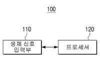
- an electronic device 100essentially includes a biosignal input unit 110 and a processor 120.
- the biosignal input unit 110is a component for receiving a biosignal of a user.
- the usermay mean a wearer who wears the electronic device 100, and the biosignal may be mainly obtained from the face of the user, which is a portion on which the electronic device 100 is worn.
- the biosignalmainly refers to a bioelectrical signal, and is generated by the electrochemical action of excitable cells which are components of nerve, muscle, and glandular tissue.
- the electronic device 100performs signal processing after measuring a desired biosignal using a sensor such as an electrode.
- the biosignalmay be obtained through various parts of the user's body other than the user's face, and in a broad sense, may include a signal detected by a user's physical motion (head rotation, nod, etc.) other than the bioelectrical signal. have.
- Bioelectric signals as bioelectric signalsinclude electromyogram (hereinafter referred to as EMG) signal, safety (Electrooculogram, EOG) signal, electroencephalogram (hereinafter referred to as EEG) signal, electrocardiogram (hereinafter referred to as ECG).
- EMGelectromyogram
- EOGsafety
- EEGelectroencephalogram
- ECGelectrocardiogram
- the signalmay include at least one of a signal, a galvanic skin response (GSR) signal, and a bioelectrical impedance analysis (BIA) signal.
- GSRgalvanic skin response
- BIOAbioelectrical impedance analysis
- the EMG signalis a signal showing muscle movement and is an electrical signal generated by muscle movement of a user's face.
- the EMG signalis basically an electrical signal generated by physiological changes occurring in the muscle fiber membrane.
- the EMG signalis mainly an electrical signal generated through muscle movement around the mouth such as a user talking or biting the molar.
- the biosignal input unit 110may receive an electrical signal detected from an electrode attached to the periphery of the eye (particularly, the bottom of the eye) as an EMG signal.
- the EOG signalis an electrical signal generated by eye movement due to the voltage difference between the corneas of the user.
- the biosignal input unit 110detects electrical signals detected from electrodes attached to the left and right sides of the eye. It can be received as an EOG signal.
- a constant dipoleis formed between the two electrodes, and the output at this time becomes zero (0).
- the + componentis output.
- the + and-componentschange according to the polarity and the direction of movement of the electrode.
- the blinking of the user's eyescan also be measured using the EOG signal, which is measured after attaching the electrodes to the top and bottom of one eye.
- the EEG signalis an electrical signal that is generated when a signal is transmitted from the nervous system to the cranial nerve. They appear differently depending on the state of mind and body and are the most important indicators for measuring brain activity.
- the EEG signalis generally detected through an electrode attached to the scalp, and the biosignal input unit 110 may receive an electric signal detected from an electrode attached to the forehead as an EEG signal.
- the ECG signalis an electrical signal generated during contraction and relaxation of the heart and is the most representative biosignal that can be easily and quickly measured on the body surface.
- the exercise of the heartis expressed in beats per minute (bpm), and changes in the autonomic nervous system can be seen through changes in heart rate.
- the ECG signalmay be measured on the face of the user, and the biosignal input unit 110 may receive an electrical signal detected from an electrode attached to various sites as an EOG signal.
- the GSR signalis generally used as an index of emotional state and is a biosignal for measuring the electrical resistance of the skin. For example, in a general arousal state, the electrical resistance of the skin is reduced, and the GSR signal may indicate the degree of change in electrical resistance of the skin according to such a characteristic. That is, the GSR signal is related to the activity of the sweat glands.
- the BIA signalis a signal that is measured by flowing an alternating current that does not harm the human body and is a biosignal that can measure the amount of moisture in the body.
- the basic principle of BIAis to estimate the body composition by measuring the electric resistance measured when a weak alternating current flows through the human body by using the characteristic that the electric current flows along the most conductive part. Body fat tissue that contains a lot of water has a low resistance even though it has excellent conductivity, and body fat tissue that contains little moisture has a low conductivity and a large resistance is measured, and this characteristic is reflected in the BIA signal.
- the biosignalmay include various types of biosignals in addition to the aforementioned signals.
- biosignal input unit 110may further include an electrostatic discharge (ESD) prevention circuit unit (not shown) for preventing an electrostatic discharge phenomenon.
- ESDelectrostatic discharge
- the biosignalmay be detected through an electrode.
- the biosignal input unit 110may receive a biosignal detected from at least one electrode in a wired or wireless manner.
- an electrode for sensing the biosignalmay be included in the electronic device 100 or may be included in the electronic device 100. It may be configured separately from.
- the electronic device 100 of the present inventionis implemented as an integrated HMD device 100A
- at least one electrodemay be included in the biosignal input unit 110.
- the electronic device 100 of the present inventionis implemented as the portable terminal device 100B detachably attached to the detachable HMD device 200
- at least one electrodeis included in the detachable HMD device 200
- the biosignal input unit ( 110may receive a bio signal detected from an electrode included in the separate HMD device 200 by wire or wireless.
- the Ag / AgCl electrode generally used when measuring a biosignalhas good signal transmission, but cannot be reused, and may have various side effects. Therefore, the electrode of the present invention does not use an electrolyte between the skin and the electrode and is made of stainless steel. It is preferable to use dry electrodes made of metal such as steel or copper. Dry electrodes convert the biopotential signals generated by ions in the body into electrical signals.
- the electrodeis an electrode for detecting a specific single type of biological signal, an electrode for detecting a plurality of types of biological signals (hereinafter referred to as a common electrode), a reference electrode, a ground electrode (ground electrode), etc. It may include.
- the reference electrodemay be configured to be in contact with the body separately from the ground electrode, and the reference electrode and the ground electrode may constitute a circuit using the same electrode. In the embodiment of the present invention, it is assumed that the reference electrode and the ground electrode are used as the same electrode for convenience.
- each electrodeSince each electrode must sense a bio-signal around the user's eye, which is a position where the electronic device 100 is fixed and mounted, in the electronic device 100 or the removable HMD device 200 implemented as the integrated HMD device 100A, It may be disposed in a position that is in contact with the eyes, and may be disposed in different positions for each type of biosignal for sensing. The attachment position and function of each electrode will be described later with reference to FIG. 3.
- the processor 120is a component that controls the overall operation of the electronic device 100.
- the processor 120may determine a biosignal to be input based on a use context of the electronic device 100.
- the context of the electronic device 100refers to current internal / external usage conditions of the electronic device 100.
- the context of the electronic device 100may include a current geographic location of the electronic device 100 or a relative location and current time with respect to a specific object. And a context such as relative time, weather, a user's current operating state, or biometric information of the user determined through a biosignal based on a specific time point.
- the screen state and usage history of the display 131 included in the electronic device 100may be included.
- the screen state of the display 131may include information about an application currently being executed or content being displayed and information about a change of a screen.
- the usage historymay include information about the applications or displayed content that has been executed from the past to the present.
- the electronic device 100may further include a communication module for receiving information from an external server through a network including various sensors (acceleration sensor, gyro sensor, geomagnetic sensor, temperature sensor, etc.) for determining the context, the Internet, and the like. Can be.
- various sensorsacceleration sensor, gyro sensor, geomagnetic sensor, temperature sensor, etc.
- the processor 120may determine the type of biosignal to be input based on the determined context. For example, when user authentication is required to use a specific application in the electronic device 100, a screen for requesting user authentication may be displayed on the display 131. The user authentication may be required when the electronic device 100 is unlocked, when logging in to a specific web site, when watching a specific content, or when using electronic payment.
- the user authenticationmay be performed through muscle movements of the face (particularly, muscle movements around the mouth) corresponding to the utterance of a specific word or sentence, in which case the detection of the EMG signal is required.
- the processor 120may determine the bio signal to receive the EMG signal around the mouth of the user.
- the processor 120may determine the biometric change through a channel corresponding to at least one electrode corresponding to a specific body part according to the use environment of the electronic device 100 among the electrodes for detecting the determined EMG signal. have. For example, in the case of a context for detecting a movement of a mouth shape according to a user's speech, the processor 120 may control to detect an EMG signal through an electrode that is placed around the user's mouth.
- a navigation screensuch as a home screen for selecting a specific application, a selection screen for selecting a specific content, and a screen for moving a cursor or a screen is displayed. Can be displayed.
- the navigationmay be performed through the movement of the pupil moving up, down, left, and right, and this requires the detection of the EOG signal.
- the processor 120may determine the biosignal to receive the EOG signal.
- a channel corresponding to an electrode(hereinafter referred to as a target electrode) for sensing the determined biosignal is selected, and a state of a channel corresponding to the selected electrode is determined.
- the biosignalmay be set according to the biosignal, and the biosignal may be determined using the biosignal input according to the set channel state.
- an embodiment in which an electrode includes a first electrode used to detect a first biosignal and a second electrode used to sense a second biosignalmay be assumed.
- the processor 120selects a channel corresponding to the first electrode as a channel to receive the biosignal and corresponds to the first electrode based on characteristics of the first biosignal. You can set the status of the channel.
- the processor 120selects a channel corresponding to the second electrode as a channel to receive the biosignal and corresponds to the second electrode based on characteristics of the second biosignal. You can set the status of the channel.
- the first electrodemay be an electrode used to detect the EOG signal on the left side, the right side, and the upper side of the user's eye.
- the second electrodemay be an electrode used to detect an EMG signal under the user's eye.
- the processor 120may include a sampling rate of a channel corresponding to a target electrode for detecting the EOG signal, an analog digital converter (ADC) resolution, and the like.
- a cutoff frequencymay be set according to the characteristics of the EOG signal. Accordingly, other bio signals (EMG signal, ECG signal, etc.) detected by the target electrode for detecting the EOG signal can be removed.
- the processor 120may determine biometric changes (movement of the pupil and movement of the facial muscle) by using the biosignal input from the target electrode according to the set channel state.
- the processor 120may control the screen of the display 131 according to the determined biometric change. For example, if the determined biometric change is eye movement or eye blink using the EOG signal, the processor 120 may select a menu or an icon or perform a navigation operation according to the eye movement or eye blink. have. In addition, when the determined biometric change is the movement of the muscle using the EMG signal, the processor 120 may determine the user's mouth shape to perform user authentication or determine a facial movement such as a wink according to the movement of the muscle. .
- the processor 120activates only a channel corresponding to the electrode for sensing the determined biosignal, and deactivates a channel other than the channel corresponding to the electrode for sensing the determined biosignal, The waste of power consumed by the electrode that is not used can be reduced.
- 2Bis a block diagram illustrating in detail a configuration of an electronic device according to another exemplary embodiment of the present disclosure.
- the electronic device 100assumes an example in which the electronic device 100 implemented as the portable terminal device 100B is attached to the detachable HMD device 200.
- the electronic device 100further includes an output unit 130, a memory 140, and a sensor unit 150 in addition to the biosignal input unit 110 and the processor 120. Descriptions already described in FIG. 2A will be omitted.
- the detachable HMD device 200may include a sensor unit 210 capable of sensing a biosignal of a user, an input unit 220 capable of receiving a user input, a communication unit 230 capable of communicating with the electronic device 100, and a memory. 240.
- the biosignal input unit 110 of the electronic device 100is a component for receiving a detected biosignal from the detachable HMD device 200.
- the biosignal input unit 110may be connected to the detachable HMD device 200 in a wired or wireless manner. It may include a communication module for performing communication. Communication with the separate HMD device 200 using the communication module may be made in various ways.
- the communication between the electronic device 100 and the detachable HMD device 200may be performed by at least one of NFC, Wi-Fi, Wi-Fi Direct, Zigbee, and Bluetooth. Can be.
- the output unit 130is a component for outputting at least one of an image signal and an audio signal.
- the output unit 130may include a display 131 for outputting an image signal, and may further include an audio output unit 132 for outputting an audio signal.
- the display 131is a component that provides a screen including various contents that can be reproduced by the electronic device 100.
- the contentmay include content in various formats, such as text, an image, a video, and a graphical user interface (GUI).
- GUIgraphical user interface
- the contentmay be implemented as VR (Visual Reality) content for providing a 3D image.
- the implementation manner of the display 131is not limited, and includes, for example, a liquid crystal display (LCD), an organic light emitting diodes (OLED) display, an active-matrix organic light-emitting diode (AM-OLED), and a plasma display panel (PDP). It can be implemented in various forms of display such as.
- the display 131may further include additional components according to the implementation manner.
- the display 131may be an LCD display panel (not shown), a backlight unit (not shown) for supplying light thereto, and a panel driving substrate for driving the panel (not shown). (Not shown).
- the audio output unit 132may be implemented as a speaker that outputs audio data (sound signal) processed by the electronic device 100.
- the processor 120may control the display 131 or the audio output unit 132 to output a result according to the determined biometric change. That is, the processor 120 may control a sound output through the screen of the display 131 or the audio output unit 132 according to the determined biometric change.
- the processor 120determines a wearing state of the detachable HMD device 200 based on a biosignal detected through an electrode for detecting a wear state of the detachable HMD device 200 by a user,
- the output unit 130may be controlled to output a result. For example, when the wearing state of the electronic device 100 is in a bad state, the processor 120 may output a warning message or a warning alarm to properly wear the detachable HMD device 200.
- the processor 120determines that the detachable HMD device 200 is not wearing, and is detachable.
- a channel corresponding to another electrode other than at least one electrode for detecting the wearing of the HMD device 200may be deactivated.
- the memory 140may store various data such as an operating system (O / S) software module for driving the electronic device 100 and various multimedia contents including VR contents.
- O / Soperating system
- the sensor unit 150controls the first to n sensors 151-1 to 151-n and the first to n sensors 151-1 to 151-n for detecting various operations performed in the electronic device 100. It includes a sensor control unit 152 for.
- the plurality of sensors 151-1 ⁇ 151-n included in the sensor unit 150are motion sensors (not shown) for detecting the movement of the electronic device 100 and sensors for user authentication.
- Iris recognition sensor(not shown) for recognizing a user's iris
- fingerprint recognition sensorfor recognizing a fingerprint
- ambient environmentair pressure, temperature, humidity, illuminance
- various sensorsfor detecting a user gesture, etc. It may include.
- the motion sensormay include at least one sensor of an acceleration sensor, a geomagnetic sensor, and a gyro sensor.
- Various sensors included in the motion sensormay detect 3D motion of the electronic device 100 through one or a combination of two or more of them.
- the acceleration sensoris a sensor that measures spatial motion of the electronic device 100. That is, the acceleration sensor refers to a sensor that detects a change in acceleration and / or a change in angular acceleration generated when the electronic device 100 moves. The acceleration sensor may detect acceleration in three axes. In addition, the acceleration sensor may detect the inclination of the electronic device 100.
- Geomagnetic sensorsare sensors that measure azimuth. That is, the geomagnetic sensor refers to a sensor for measuring azimuth by sensing a magnetic field formed in the north-south direction of the earth.
- the geomagnetic sensorcan detect geomagnetism in three axes.
- the north direction measured by the geomagnetic sensormay be magnetic north. However, even if the geomagnetic sensor measures the direction of magnetic north, it is of course possible to output the true north direction through internal calculation.
- the gyro sensoris an inertial sensor that measures the rotational angular velocity of the electronic device 100. That is, it means a sensor that can know the current direction by using the inertial force of the rotating object.
- the gyro sensorcan measure the rotational angular velocity in two axes.
- the motion sensormay sense a movement of the electronic device 100 to recognize a direction in which the electronic device 100 moves, a rotational angular velocity, and the like.
- the sensor controller 152is configured to collectively control the first to n sensors 151-1 to 151-n, and serves as a sensor hub. According to an embodiment of the present disclosure, when the electronic device 100 operates in a sleep mode, such as a standby mode or a power save mode, power supplied to the controller 120 is limited, but is detected by the sensor module even in the sleep mode. In order to continuously perform, the sensor unit 150 may be supplied with minimal power. That is, the sensor controller 152 may determine the context of the electronic device 100 based on the signals detected by the sensors 151-1 ⁇ 151-n, and wake up the controller 120. have. While the controller 120 wakes up, the sensor controller 152 may transmit a control signal to the detachable HMD device 200 to sense the biosignal determined based on the determined context.
- a sleep modesuch as a standby mode or a power save mode
- the sensor unit 150may be supplied with minimal power. That is, the sensor controller 152 may determine the context of the electronic device 100 based on the signals detected by the sensors
- the sensor unit 210 of the removable HMD device 200may include a plurality of electrodes for sensing the user's bio-signals.
- the plurality of electrodesmay include electrodes for sensing various biological signals such as an EMG signal, an EOG signal, an EEG signal, an ECG signal, a GSR signal, and a BIA signal.
- the plurality of electrodesmay be attached to a pad portion in contact with the skin of the user in the detachable HMD device 200, and each electrode may be attached at an appropriate position according to the type of biosignal to be detected on the pad.
- the input unit 220is a component for receiving various inputs of a user and may include a physically implemented button or a touch pad.
- the input unit 220may include a call button, a brightness control button, a volume control button, and the like, and is connected with content displayed on the electronic device 100 to play content or control a function of the content. It can receive an input such as.
- the communication unit 230is a configuration for performing wired / wireless communication with the electronic device 100, and a description of the communication module included in the biosignal input unit 110 of the electronic device 100, and its configuration and function will be duplicated. Is omitted.
- the memory 240stores a biosignal detected through the sensor unit 210.
- the processor 250may control the memory 240 to store the biosignals detected through the electrodes in order to receive a plurality of biosignals through the one electrode.
- the processor 250may pass the stored biosignals through different filters and receive the biosignals corresponding to the respective filters.
- the processor 250is a component for overall control of the detachable HMD device 200.
- the processor 250may remove noise by filtering the biosignal detected through the sensor unit 210, and the user wears or detaches the detachable HMD device 200 based on characteristics of the detected biosignal. It can be determined whether or not.
- whether the user wears the HMD device 200may be determined based on the various types of bio signals described above, but is not particularly limited, but is preferably determined using the EMG signal.
- the wakeup signalmay be transmitted to the electronic device 100 in the sleep mode.
- the useroutputs a signal indicating that wearing is not performed properly (in this case, the detachable HMD device 200 provides a predetermined notification to the user). It may include an LED or a speaker that can be provided), a signal for outputting a signal indicating that the wearing is not properly worn to the electronic device 100.
- the processor 250measures the signal quality of the biosignal detected through the sensor unit 210 and based on the measured signal quality, outputs a warning indicating that the signal quality detected by the specific electrode is poor. May be transmitted to the electronic device 100.
- the processor 250may output a warning that the signal quality detected by the specific electrode is poor through the LED or the speaker provided to the detachable HMD device 200.
- FIG. 2Bhas described the configuration and operation of the electronic device 100 and the detachable HMD device 200 when the electronic device 100 is implemented as the portable terminal device 100B. Even when the device 100 is implemented as an integrated HMD device 100A, a person having ordinary skill in the art may easily design changes and apply the same.
- the configuration and operation of the sensor unit 210 included in the detachable HMD device 200may be performed by the sensor unit 150 of the electronic device 100.
- the input / output module 220will be included in the electronic device 100.
- the memory 240may be integrated into the memory 140 of the electronic device 100, and the communication module included in the communication unit 230 and the biosignal input unit 110 may be omitted.
- the operation of the processor 250may be integrated into the operation of the processor 120 of the electronic device 100.
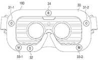
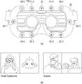
- FIG 3is a view for explaining each electrode for detecting a bio-signal according to an embodiment of the present invention.
- FIG. 3is a front view of the electronic device 100 implemented as the integrated HMD device 100A or the detachable HMD device 200 viewed from a wearing surface thereof.
- the pad 30 adhering to the wearer's face around the eyesis used to detect the EMG signal and the electrodes 31-1, 31-2, 32 used to detect the EOG signal.
- the electrodes 33-1 and 33-2 and the reference electrode 34may be provided.
- a pair of electrodes 31-1 and 31-2are attached to the left and right sides of the eye to detect an EOG signal. Since each electrode 31-1 and 31-2 calculates one electrode change, the pair of electrodes 31-1 and 31-2 can specify only the left and right directions. Therefore, in order to set the direction of the eyeball, it is necessary to set two directions of up, down, left and right, and at least one electrode 32 may be additionally provided at the pad 30 to be attached to the lower end of the eye.
- the processor 120specifies a pair of electrodes 31-1 and 31-2 attached to the left and right sides of the eye to specify the left and right directions of the eye, and the pair of electrodes attached to the right and the bottom of the eye ( 31-1, 32, or a pair of electrodes 31-2 and 32 attached to the left and the bottom of the eye can specify the vertical direction of the eye.
- at least one electrodemay be additionally provided on a pad that adheres to the upper end of the eye, and the processor 120 uses the additionally provided upper electrode and lower electrode 32 as a pair. It is also possible to specify the vertical direction of the eye.
- a pair of electrodes (33-1, 33-2) for detecting the EMG signalmay be attached to the lower end of both eyes.
- One electrodeis attached to one muscle, and one value is calculated.
- the processor 120may store the movement intensity of each muscle according to the electric strength for each muscle and convert the magnitude of the detected EMG signal.
- the electrodes 33-1 and 33-2 for sensing the EMG signalmay be provided in an annular shape around the pad 30, and the electrodes 33-1 and 33-2 are the movements of muscles throughout the face. Can be detected.
- the electrodes 33-1 and 33-2 for detecting the EMG signal on the pad 30adhered to the lower ends of both eyes to detect the movement of muscles around the eyes and cheekbones that mainly change the shape of the face. Each may be provided.
- a reference electrode (34)is additionally provided, and through the signal and the reference electrode 34 sensed through both electrodes (33-1, 33-2) The difference value of the detected signal can be used as an EMG signal.
- the reference electrode 34may be located on the pad 30 that adheres to the upper middle portion of both eyes.
- an additional pair of electrodes for detecting an EMG signalis provided, and when using a bi-polar method for detecting an EMG signal using a potential difference between adjacent electrode pairs, a reference electrode 34 is required. You can not.
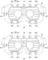
- FIG. 4is a diagram for describing a common electrode for sensing a biosignal according to another exemplary embodiment.
- the electrode according to an embodiment of the present disclosuremay be a common electrode 36-1 or 36-2 used to detect any one biosignal determined based on the context of the electronic device 100 among the EOG signal and the EMG signal. It may further include.
- the processor 120selects a channel corresponding to the common electrodes 36-1 and 36-2 as a channel to receive the determined biosignal and based on the determined characteristics of the biosignal.
- the state of the channels corresponding to the common electrodes 36-1 and 36-2can be set.
- the processor 120adjusts the sampling rate and ADC resolution for detecting the biosignal and filters the EOG signal according to the determined biosignal based on the signal detected from the common electrodes 36-1 and 36-2.
- the EOG signal and the EMG signalcan be separated by passing through either one of the filter for beating and the filter for filtering the EMG signal.
- the electronic device 100 or the separate HMD device 200 implemented as the integrated HMD device 100Amay include at least one common electrode, and FIG. 4 shows a pair of common electrodes 36-1 and 36-2. The example provided in the position which adhere
- the electrodes 31-1, 31-2, 35-1, and 35-2 for sensing the EOG signalmay be provided in pairs at the left and right sides of both eyes and at the upper ends of both eyes.
- the common electrodes 36-1 and 36-2 of FIG. 4may be used as electrodes for sensing the EMG signal or electrodes for sensing the EOG signal according to the context of the electronic device 100. For example, if it is determined that the context of the current electronic device 100 is 'navigating', the processor 120 may determine the type of biosignal to be input as the EOG signal. In this case, the processor 120 may determine the left and right directions of the eyes using the pair of common electrodes 36-1 and 36-2, and the pair of common electrodes 36-1 and 36-2. The eye of the eye may be determined by using any one of any one of the electrodes 35-1 and 35-2.
- the processor 120may determine the type of the biosignal to be input as the EMG signal. In this case, the processor 120 may determine the movement of the facial muscles using the pair of common electrodes 36-1 and 36-2 and the reference electrode 34.
- the common electrodes 36-1 and 36-2are electrodes commonly used to detect an EOG signal or an EMG signal according to the context of the electronic device 100.
- the common electrodes 36-1 and 36-2may be bio signals together with the other electrodes 31-1, 31-2, 33-1, 33-2, 34, 35-1, and 35-2. It can be used to detect.
- the processor 120may set a state of a channel corresponding to the common electrodes 36-1 and 36-2 according to the characteristics of the biosignal. In detail, as described above, the processor 120 sets the sampling rate, the cutoff frequency, the ADC resolution, and the like of the channel corresponding to the common electrodes 36-1 and 36-2 to match the characteristics of the determined biosignal. Only an electrical signal for the biosignal may be input.
- FIG. 5is a diagram for describing each signal flow process in an electronic device according to an embodiment of the present disclosure.
- FIG 5illustrates a process in which a biosignal detected from a plurality of electrodes 211 provided in the detachable HMD device 200 is input to and processed by the tank device 100 mounted in the detachable HMD device 200. It is shown.
- the bio signals detected by the plurality of electrodes 211are transmitted to the electronic device 100 through the channels 41-1 to 41-n corresponding to the electrodes 211.
- the EMG signalis converted into a digital signal via an analog-to-digital converter (ADC) 214. Therefore, the separate HMD device 200 is composed of 1 an analog front end for processing analog signals starting from the ADC 214 and 2 a digital circuit for processing digital signals converted from analog signals. do.
- ADCanalog-to-digital converter
- the analog front endincludes the operation of the sensor unit 210. Specifically, an electrode 211 for detecting a biosignal, an amplifier (AMP) 212 for amplifying the detected biosignal, and a high pass filter (HPF) / low pass filter (LPF) for removing noise of the amplified biosignal ) And the operation of the ADC 214 to convert the noise-free biosignal into a digital signal.
- the digital circuitis a component for processing a digital signal converted into a digital, the processor 250 and the electronic device 100 to perform filtering through HPF (High Pass Filter) / LPF (Low Pass Filter) And a communication unit 230 for transmitting the filtered digital biosignal.
- the processor 250is implemented as a micro controller unit (MCU).
- the biosignalis an EMG signal
- the potential difference between the reference voltages sensed through the reference electrode 34may be detected.
- the EMG signal including the detected potential differenceis amplified by the amplifier 212 provided in the isolated HMD device 200, and the amplified EMG signal is noised through the HPF / LPF 213 provided in the isolated HMD device 200. Can be removed.
- the HPFmay remove noise of the DC component from the amplified EMG signal
- the LPFmay remove noise other than the DC component from the amplified EMG signal.
- the noise-free EMG signalis converted into a digital signal through the ADC 214, and after the high pass and low pass filtering process in the MCU 250, is transmitted to the communication unit 230, the electronic communication is connected in real time Sent to device 100.
- the processor 120selects a channel corresponding to the target electrode or the common electrode from among the channels 41-1 to 41-n as a channel to receive the determined biosignal, and based on the characteristics of the determined biosignal. Alternatively, the state of the channel corresponding to the common electrode may be set.
- the processor 120may provide information about the determined biosignal through the communication module included in the biosignal input unit 110. And transmit to 200.
- the communication method of the biosignal input unit 110 of the electronic device 100 and the communication unit 230 of the detachable HMD device 200may be wired or wireless.
- communication between the biosignal input unit 110 of the electronic device 100 and the communication unit 230 of the detachable HMD device 200is wireless
- NFC, Wi-Fi, and Wi-Fi Directmay be implemented to perform communication in at least one of the manner, in addition, it may be implemented to perform communication using a variety of wireless communication schemes.
- the Universal Asynchronous Receiver / Transmitter(UART)
- the communicationmay be implemented in various ways, including in a manner.
- the MCU 250may determine what kind of biosignal is determined. In response to the determination, the channel corresponding to the target electrode for detecting the biosignal is selected according to the determined biosignal type. Thereafter, the MCU 250 may set at least one of the sampling rate, the ADC resolution, and the cutoff frequency of the biosignal received through the selected channel according to the characteristics of the determined biosignal, such as the HPF / LPF 213 and the ADC 214. Can be controlled. That is, the MCU 250 may control the sensor unit 210 to perform software filtering.
- the ADC 214may transmit the bioelectrical signal converted into a digital signal to the MCU 250 only through the selected channel according to the determined biosignal type. Accordingly, the MCU 250 may receive the detected biosignal only through a specific channel selectively according to the context, without receiving the detected biosignal through all channels. That is, the MCU 250 may control the ADC 214 to ignore, without processing, a signal received through a channel other than the channel selected according to the context.
- the processor 120may control the sentient signal input unit 110 to transmit information indicating that the determined biosignal is the EOG signal to the communication unit 230.
- the MCU 250selects a channel corresponding to the target electrode for detecting the EOG signal, and transmits only the EOG signal transmitted to the selected channel to the MCU 250. ) Can be controlled.
- the MCU 250may filter the remaining signals except for the EOG signal from the biosignal transmitted through the selected channel by setting the sampling rate and the cutoff frequency of the detected biosignal to correspond to the amplitude and the period of the EOG signal. .
- the MCU 250controls the power supplied to any one of the AMP 212, the HPF / LPF 213, and the ADC 214 so that the biosignal is not transmitted through a channel other than the selected channel. can do. That is, the AMP 212, the HPF / LPF 213, and the ADC 214 may be supplied with power for each channel.
- the MCU 250activates only a channel corresponding to the electrode for sensing the determined biosignal, and deactivates a channel other than the channel corresponding to the electrode for sensing the determined biosignal, The waste of power consumed by the electrode that is not used can be reduced.
- the MCU 250may measure an input state of the biosignal and change a channel to which the biosignal is input according to the measured input state of the biosignal. Specifically, the MCU 250 determines the contact state or impedance value of the target electrode with respect to the site where the bio signal is to be detected, and the contact state of the target electrode is poor (for example, the size of the detected bio signal is preset). If it is determined that the impedance value is higher than the preset value (for example, if the makeup is dark on the user's face), the target electrode may be replaced with another electrode measuring the same type of biosignal. You can change it. Even when there are a plurality of reference electrodes, the reference electrodes may be changed based on the contact state of the reference electrodes or the impedance value of the BIA signal.
- a pair of electrodes 33-1 and 33-2 for detecting an EMG signal under the eyemay be set as a target electrode for detecting an EMG signal, but a pair of electrodes may be used.
- the MCU 250may fail among the common electrodes 36-1 and 36-2 instead of the corresponding bad electrode.
- the target electrodemay be changed to receive an EMG signal from any one close to the electrode. For example, the bottom of the left eye of the pair of electrodes 33-1 and 33-2 and the right of the pair of common electrodes 36-1 and 36-2 according to the input state of the EMG signal.
- a pair of lower common electrodesmay be used to receive an EMG signal.
- the input state of the biosignalmay be measured using not only an impedance value of the biosignal, but also a signal-to-noise ratio (SNR), a common mode rejection ratio (CMRR), and the like. .
- SNRsignal-to-noise ratio
- CMRRcommon mode rejection ratio
- the embodiment illustrated in FIG. 5is an example in which the electronic device 100 implemented as the portable terminal device 100B is attached to and detached from the detachable HMD device 200.
- the detachable HMD device 200is illustrated, and the above-described disclosure describes the operations of the electronic device 100 and the detachable HMD device 200, respectively.
- the technical idea illustrated in FIG. 5may be applied in the same manner.
- the operation of the MCU 250 of the detachable HMD device 200 of FIG. 5may be performed by the processor 120 of the electronic device 100, and the detachable HMD device 200 for communicating with the electronic device 100 may be used.
- the communication unit 230may be omitted.
- the electronic device 100 of the present inventionis assumed to be an integrated HMD device.
- the technical idea of the present invention described belowmay be applied to the case where the electronic device 100 of the present invention is implemented as a portable terminal device detachable from a detachable HMD device equipped with a sensor.
- FIG. 6is a diagram illustrating an EOG signal and an EMG signal according to an embodiment of the present invention.
- FIG. 6Aillustrates a waveform of an EOG signal sensed by an electrode or a common electrode used to sense an EOG signal.
- FIG. 6Billustrates a waveform of the EMG signal sensed by the electrode or the common electrode used to sense the EMG signal.
- the EOG signal shown in FIG. 6Aincludes an EMG signal
- the EMG signal shown in FIG. 6Bincludes an EOG signal. May appear.
- the processor 120may derive the waveform 62 of the EMG signal as shown in (c) of FIG. 6 by dividing the signal of (b) from the signal of (a). Meanwhile, the processor 120 may derive the waveform 61 of the EOG signal by differentiating the waveform 62 of the EMG signal derived from the signal of (a).
- FIG. 7is a flowchart for briefly describing an operation process of an electronic device according to an embodiment of the present disclosure.
- Operation of the electronic device 100may be classified into three stages. Detecting a wearing state of the electronic device 100 (S710), determining a signal quality of the detected biosignal (S720), and processing the detected biosignal to perform an operation according to a user's biometric change. Step S730.
- the wearing state of the electronic device 100may be determined from a biosignal detected through an electrode of the electronic device 100 and input to the biosignal input unit 110.
- the electronic device 100may be determined using a BIA signal among the electrodes.
- the biosignal input unit 110may be supplied with a minimum power for detecting the biosignal. That is, while the electronic device 100 operates in the sleep mode, when the biosignal is detected, the electronic device 100 may switch to the normal mode (state in which power is normally supplied).
- the electronic device 100when the electronic device 100 is in the sleep mode, minimal power is supplied to the sensor unit 150, and the movement of the electronic device 100 is detected through the sensor unit 150. Power may be supplied to the 110 to receive a biosignal.
- the electronic device 100may determine whether the electronic device 100 is worn by a user by using characteristics of a biosignal detected from an electrode at a specific location.
- the characteristic of the specific biosignal detected from the electrode at the specific position when the user wears the electronic device 100 properlyis stored in the memory 140, and the characteristic of the specific biosignal stored in the memory 140 and the currently detected specific
- the electronic device 100may output a warning message or a warning alarm to properly wear the electronic device 100 through the output unit 130.
- step S720the quality of the biosignal input through the biosignal input unit 110 is determined.
- the state of the channel corresponding to the plurality of electrodesmay be activated to receive all the bio signals detected from the plurality of electrodes included in the electronic device 100. Accordingly, the electronic device 100 may determine all the quality of signals detected from the plurality of electrodes.
- the electronic device 100compares a signal detected from a plurality of electrodes with a normal signal that is normally detected, and if it is determined that the signal quality of a particular electrode is poor, outputs a warning to replace the corresponding electrode or determines that the signal quality is poor.
- the biosignalmay be detected through another electrode around the electrode.
- the signal qualityis the signal-to-noise ratio (SNR), the magnitude of the amplitude of the signal current in the time domain, and the range of the signal current in the frequency domain. It can be determined through analysis of at least one of the.
- SNRsignal-to-noise ratio
- the biosignal to be inputis determined based on the current context of the electronic device 100, and the biosignal is received and processed.
- the electronic device 100sets a state of a channel corresponding to an electrode for sensing the determined biosignal according to the determined biosignal, and determines a biometric change by using an input biosignal according to the set channel state.
- various operationsmay be performed. An operation performed according to the biometric change will be described in detail with reference to the embodiments shown in FIGS. 9 to 12.
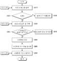
- FIG. 8is a flowchart illustrating an operation process of an electronic device in detail according to an embodiment of the present disclosure.
- the electronic device 100detects and receives a specific biosignal through an electrode for detecting a wearing state of the electronic device 100 (S810).
- the biological signal detected for wearingis an EMG signal, but is not necessarily limited thereto, and whether the biological signal is worn is determined by various biological signals.
- the electronic device 100is lifted by the user, the movement of the electronic device 100 is sensed by the motion sensor 160 included in the electronic device 100, and whether the electronic device 100 is worn is checked.
- a channel corresponding to an electrode capable of sensing the EMG signal for determiningmay be activated.
- the electronic device 100receives a biosignal detected from the electrode and records the input biosignal (S830). If it is determined that the electronic device 100 is not worn (S820: N), a channel corresponding to some electrodes or all electrodes may be deactivated to reduce power consumption due to activation of the electrodes.
- the electronic device 100may output a result according to the determination of the wearing state of the electronic device 100. If the wearing state is poor, a message or guide voice indicating that wearing is not properly performed may be output. If the wearing state is good, a message or guide voice indicating wearing is properly output.
- the quality of the input biosignalis measured and it is determined whether the quality of the measured biosignal is greater than or equal to an acceptable level (S850).
- the measured quality of the biosignalmay be measured using not only the impedance of the biosignal, but also SNR, CMRR, and the like, and if the measured value is greater than or equal to a preset threshold, it may be determined that the quality is poor. Similarly, if the measured value is less than the preset threshold, it can be determined that the quality is good.
- the output unit 130If it is determined that the quality of the measured biosignal is poor (S850: N), the output unit 130 outputs a warning message or a warning sound indicating that the electrode is defective, or surrounds the corresponding defective electrode having a poor quality of the measured biosignal. It is possible to detect a biosignal by replacing with another electrode.
- the context of the electronic device 100is determined (S860).
- the electronic device 100determines a biosignal to be input based on the determined context, and activates a channel corresponding to an electrode for sensing the determined biosignal (S880).
- the electronic device 100may process the biosignal by setting a state of a channel corresponding to an electrode for sensing the determined biosignal to a suitable state for receiving the determined biosignal based on the context (S890). In this case, the electronic device 100 may set a sampling rate, an ADC resolution, and a cutoff frequency of a channel corresponding to the electrode for detecting the determined biosignal.
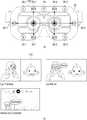
- 9 to 12are diagrams for describing an operation of an electronic device according to various usage environments according to an embodiment of the present disclosure.
- FIG 9illustrates a case where the context of the electronic device 100 is an environment in which a screen for user authentication is displayed.
- the pads 30 contacting the face of the electronic device 100may include electrodes 31-1, 31-2, and 35 for detecting an EOG signal and an EMG signal. Electrodes 33-1, 33-2, 37 for sensing the common electrode 36, reference electrode 34, and ground electrodes 38-1, 38-2 for detecting both the EOG signal and the EMG signal It may be provided.
- the common electrode 36 at the lower right eyemay detect both the EMG signal or the EOG signal, but the processor 120 performs filtering to filter the EMG signal or the EOG signal based on the context of the electronic device 100.
- the EMG signal or the EOG signalmay be selectively input.
- a message “Please unlock and dock after unlocking”is output when the user first wears the electronic device 100.
- the userneeds to release the lock of the electronic device 100 and wear it again.
- the userlocks using the biosignal of the user without removing the electronic device 100. You can turn it off.
- the lockmay be released using an EOG signal, an EMG signal, and a voice signal input through a microphone (not shown) included in the electronic device 100.
- the display 131may display a message “say unlock” on one side of the screen requesting unlocking.
- the processor 120may control the lock to be released when the user utters "unlock” while looking at the message "say unlock”.
- the processor 120may be based on this context (user authentication) of the electronic device 100.
- the EOG signal for detecting the gaze of the user and the EMG signal for detecting the user's mouthmay be determined as a biosignal to be input.
- the processor 120corresponds to a channel corresponding to the electrodes 31-1, 31-2, 35, and 36 for receiving an EOG signal and an electrode 33-1, 33-for receiving an EMG signal according to the determined biosignal. 2 and 37 may be activated, and the biosignal may be input through the activated channel.
- the common electrode 36may be further included. In this case, the two EOG signals and the EMG signals sensed through the common electrode 36 may be separated from each other through filtering.
- the processor 120uses the EOG signals detected from the electrodes 31-1, 31-2, 35, and 36 around the binocular to respond to the message "say unlock” displayed on one side of the screen.
- Condition 1the condition that the voice signal detected through the microphone is recognized as “unlock” (condition 2), and the EMG signal detected from the electrodes 33-1, 33-2, 36, 37 around the mouth.
- condition 3the condition that the voice signal detected through the microphone is recognized as “unlock”
- the screen lockmay be released only when an already authenticated user directly ignites "unlock” by wearing the electronic device 100. Therefore, when the user plays the recorded sound without direct utterance, the lock can be prevented from being released and the security can be enhanced.
- the userBy detecting the EMG signal in a noisy environment, the user can determine whether the user has uttered "unlock". It can be used as an auxiliary means of microphone to recognize the user.
- FIG. 10illustrates a case in which the context of the electronic device 100 is an environment in which a screen for recognizing facial expressions is displayed.
- the pads 30 contacting the face of the electronic device 100may include electrodes 33-1 and 33-2, EOG, and EMG signals for detecting an EMG signal.
- Common electrodes 36-1, 36-2, 39-1, 39-2, 40-1, and 40-2, a reference electrode 34, and a ground electrode 38may be provided to detect all of them.
- the common electrodes 36-1, 36-2, 39-1, 39-2, and 40may detect both EOG and EMG at the position attached to the eye on the pad 30. -1, 40-2) may be provided.
- FIG. 10Billustrates a screen on which an expression recognition application that recognizes a user's facial expression change (viewing direction and mouth movement) and displays a fish for tracking the facial expression of the user is executed.
- the expression of the fish including the position or mouth of the fish's eyesmay be changed.
- a change in gaze of a usermay be sensed based on the movement of the monocular or the movement of both eyes.
- the common electrodes 40-1 and 40-2near the temple of both eyes and the common electrodes 36-1 and 39- that are attached to the upper and lower sides of either eye. 1 or 36-2 or 39-2
- a change in the line of sight of the usermay be sensed.
- a shortcut command based on the shape of the user's mouthmay be pre-stored, and the user's mouth recognized through the electrodes 33-1, 33-2, 36-1, and 36-2 for detecting the EMG signal.
- the corresponding shortcut commandmay also be executed. That is, the user may use the electronic device 100 in a hands-free manner.
- the shortcut commandmay include “Home” for displaying a home screen (O / S of the electronic device 100 or a content selection screen displayed by default when a specific application is executed), “Back” for returning to a previous screen, “Select” for selecting a specific menu or content, "Volume” for adjusting the volume, and the like.
- the processormay recognize a mouth shape in which a user pronounces "Home,” and display a home screen.
- the processor 120When a screen for performing facial expression recognition is displayed on the display 131 (for example, when a facial expression recognition application is executed), the processor 120 is based on the context (expression recognition) of the electronic device 100.
- the EMG signal for recognizing the facial expression of the user and the EOG signal for detecting the gaze of the usermay be determined as the biosignal to receive the processor 120.
- the processor 120receives the EOG signal and the EMG signal according to the determined biosignal.
- a single type of biological signalmay be detected, such as electrodes 33-1 and 33-2 capable of detecting an EMG signal.
- the common electrodes 36-1, 36-2, 39-1, 39-2, 40-1, and 40-2can sense not only the electrodes but also the EOG signal and the EMG signal.
- the processor 120may track a user's head by using a motion sensor included in the electronic device 100.
- the EOG signal detected from the movement of the left eyeis greater than the EOG signal detected from the movement of the right eye, and when the user's head rotates to the right, the motion of the right eye is detected.
- the EOG signalis greater than the EOG signal detected from the movement of the left eye.
- the processor 120may selectively receive one of the safety signal corresponding to the left eye or the safety signal corresponding to the right eye according to the rotation direction of the user's head using the motion detection sensor. For example, when the user's head is rotated to the left or right, the processor 120 may detect an EOG signal in a channel or right eye corresponding to the electrodes 36-1, 39-1, and 40-1 for detecting an EOG signal in the left eye. By selectively activating channels corresponding to the electrodes 36-2, 39-2, and 40-2 for detecting the signals, the gaze movement of the user may be determined using only the monocular EOG signal.
- the pads 30 contacting the face of the electronic device 100may include electrodes 32-1, 32-2, and 33-1 for detecting an EMG signal. , 33-2, 41-1, 41-2, 42-1, and 42-2, the reference electrode 34 and the ground electrode 38 may be provided.
- the processor 120may recognize the facial expression of the user based on the context (expression recognition) of the electronic device 100.
- the EMG signalmay be determined as a biosignal to be input.
- the EOG signalmay be additionally input using some electrodes around the eyes among the electrodes for detecting the EMG signal.
- the processor 120receives a signal input from any one of the electrodes for detecting the EMG signal.
- the EOG signalcan be additionally input by passing the filter corresponding to the EOG signal (passing only the EOG signal, and filtering the remaining signal).
- the EMG signalmay not recognize the wink accurately. Therefore, in this case, by receiving an additional EOG signal, it is possible to further increase the accuracy of facial expression recognition.
- the user blinks both eyesit is possible to more accurately recognize whether the blink operation is an unconscious blink or a conscious blink using the additionally recognized EOG signal.
- the processor 120may separately store a signal (low data) detected through an electrode for detecting an EMG signal, and pass the low data through a filter corresponding to the EOG signal to receive an additional EOG signal. have.
- FIG. 11Aillustrates an embodiment of detecting an EMG signal by using the reference electrode 34 (an example of detecting a bio-signal by unipolar), an adjacent electrode pair without the reference electrode 34 is illustrated. It is also possible to detect the EMG signal by using the potential difference of (). In detail, in order to detect mouth movements (such as ' ⁇ ', ' ⁇ ', etc.) that require a specific muscle of the user, a bipolar biosignal detection method is used rather than a unipolar biosignal detection method. May be used.
- the pads 30 contacting the face of the electronic device 100may include electrodes 32-1, 32-2, and 33-1 for detecting an EMG signal. , 33-2, 42-1 and 42-2, electrodes 43-1 and 43-2 for detecting an EEG signal, reference electrode 34 and ground electrodes 38-1 and 38-2 Can be.
- the left electrode 43-1 for detecting the EEG signalis a first front point (hereinafter, fp1) of the frontal lobe region
- the right electrode 43-2 for detecting the EEG signalis a second front point (hereafter, for the EEG signal).
- fp2can detect the concentration / emotion signals generated respectively.
- the processor 120determines an EEG signal for recognizing a user's emotion. May be determined as a biosignal to be input.
- the processor 120may activate a channel corresponding to the electrodes 43-1 and 43-2 for detecting the EEG signal and set the state of the activated channel to an appropriate state for receiving the EEG signal.
- the pads 30 contacting the face of the electronic device 100may include electrodes 44-1 and 44-2 and a BIA signal for detecting a GSR signal.
- the electrodes 45-1, 45-2, 46-1, 46-2, the reference electrode 48, and the ground electrodes 38-1, 38-2may be provided to detect the PSA.
- the processor 120may determine a GSR signal and a BIA signal for recognizing a user's emotion as a biosignal to be input.
- the processor 120measures the change in the degree of hydration of the facial skin through the electrodes 44-1 and 44-2 for detecting the GSR signal, and the electrodes 45-1, 45-2 and 46 for detecting the BIA signal. -1, 46-2) can be used to measure the bioelectrical resistance of facial skin.
- the processor 120is connected to the electrodes 44-1, 44-2 for detecting the GSR signal and the electrodes 45-1, 45-2, 46-1, 46-2 for detecting the BIA signal.
- Each of the corresponding channelsmay be activated, and the state of each activated channel may be set to an appropriate state for receiving the GSR signal and the BIA signal.
- the electrodes 30-1 and 47-2which generate electrical muscle stimulation (EMS) signals to the pad 30 in contact with the face of the electronic device 100 to apply electrical stimulation to the facial muscles.
- EMSelectrical muscle stimulation
- the processor 120determines that the context needs to move specific muscles of the face, the processor 120 moves the specific muscles of the face through the electrodes 47-1 and 47-2 that generate EMS signals, thereby actively operating the electrodes. It may be.
- FIG. 13is a block diagram illustrating a configuration of an electronic device in detail according to another exemplary embodiment.
- the electronic device 100 ′may include a biosignal input unit 110, a processor 120, an output unit 130, a memory 140, and a sensor unit 150. ), A communication unit 160, an audio processor 170, a video processor 180, and a user interface 190.
- a description of a portion overlapping with the description in FIG. 2Awill be omitted.
- the processor 120includes a ROM 121, a RAM 122, a CPU 123, a graphics processor 124, and first to n interfaces 125-n to 125-n.
- the ROM 121, the RAM 122, the CPU 123, the graphics processor 124, and the first first interface 125-1 to the n interface 125-nmay be connected to each other through the bus 126. .
- the CPU 123accesses the storage 140 and performs booting using the O / S stored in the storage 140.
- the CPU 123stores various programs and contents stored in the storage 140. And various operations may be performed using data and the like.
- the ROM 121stores a command set for system booting.
- the CPU 123copies the O / S stored in the storage 140 to the RAM 122 according to the command stored in the ROM 121, and executes the O / S.
- Boot upWhen the booting is completed, the CPU 123 copies various application programs stored in the storage 140 to the RAM 122 and executes the application programs copied to the RAM 122 to perform various operations.
- the graphic processor 124generates a screen including various objects such as an icon, an image, and a text by using a calculator (not shown) and a renderer (not shown).
- the calculatorcalculates attribute values such as coordinates, shapes, sizes, and colors for displaying the objects according to the layout of the screen.
- the renderergenerates screens of various layouts including objects based on the attribute values calculated by the calculator.
- the first interface 125-1 to the n interface 125-nare connected to the aforementioned various components.
- One of the interfacesmay be a network interface connected to an external device through a network.
- the above-described operation of the processor 120may be performed by executing a program stored in the storage 140.
- the display 131is a component that provides a screen including various contents that can be played by the electronic device 100 ′.
- the contentmay include content in various formats, such as text, an image, a video, and a graphical user interface (GUI).
- GUIgraphical user interface
- the contentmay be implemented as VR content for providing a 3D image.
- the audio output unit 132is configured to output audio processed by the audio processor 170.
- the memory 140may store various data such as an operating system (O / S) software module for driving the electronic device 100 ′ and various multimedia contents.
- O / Soperating system
- the memory 140may include a base module for processing signals transmitted from hardware included in the electronic device 100 ′, a storage module for managing a database or registry, and graphic processing for generating a screen of a layout. Modules and security modules can be stored.
- the sensor unit 150is a component for detecting various operations performed in the electronic device 100. Since the detailed configuration of the sensor unit 150 has been described with reference to FIG. 2B, a description thereof will be omitted.
- the communication unit 160is configured to communicate with an external device according to various types of communication methods, and may be implemented separately from the biosignal input unit 110.
- the communication unit 160may include a Wi-Fi chip, a Bluetooth chip, a wireless communication chip, and the like, and may communicate with another electronic device including a server.
- the audio processor 170is a component that processes audio data, and the processed audio data is output through the audio output unit 132.
- the video processor 180is a component that performs various image processing such as decoding, scaling, noise filtering, frame rate conversion, resolution conversion, and the like for the content.
- the user interface 190is a component for detecting a user interaction for controlling the overall operation of the electronic device 100 ′.
- the user interface 190may include a microphone (not shown), a camera (not shown), or the like.
- the microphoneis configured to receive a voice spoken by a user of the electronic device 100 'or a sound around the electronic device 100'. Voice recognition, sound recognition or recording is performed through the microphone.
- FIG. 14is a flowchart illustrating a control method of an electronic device according to an embodiment of the present disclosure.
- a biosignal to be inputis determined based on a usage context of the electronic device (S1410).
- a state of a channel corresponding to the electrode for sensing the determined biosignalis set (S1420).
- the channel corresponding to the electrode for detecting the determined biosignalmay be activated, and a channel other than the channel corresponding to the electrode for detecting the determined biosignal may be deactivated.
- the electrodemay include a common electrode used to detect any one biosignal among the plurality of biosignals determined based on a usage environment of the electronic device.
- the common electrodemay be an electrode used for detecting a biosignal of any one of a safety signal and an EMG signal under the user's eye.
- the channel corresponding to the common electrodemay be selected as a channel to receive the determined biosignal, and the state of the channel corresponding to the common electrode may be set based on the characteristics of the determined biosignal.
- At least one of a sampling rate, an ADC resolution, and a cutoff frequency of a channel corresponding to an electrode for sensing the determined biosignalmay be set based on the characteristics of the determined biosignal.
- control method of the electronic devicemay first measure the quality of the biosignal detected through the electrode and determine a channel through which the biosignal is input based on the measured quality of the biosignal.
- the biometric changeis determined using the biosignal input according to the set channel state (S1430).
- the biometric changemay be determined through a channel corresponding to at least one electrode corresponding to a specific body part according to the use environment of the electronic device.
- control method of the electronic devicemay output a result according to the determined biometric change.
- the screen of the display included in the electronic devicemay be controlled according to the determined biometric change.
- the biosignal requiring sensing according to the use environment of the electronic devicemay be input using only the channel of the corresponding electrode, and the biosignal requiring sensing the state of the corresponding channel.
- the biosignal requiring sensingmay be input using only the channel of the corresponding electrode, and the biosignal requiring sensing the state of the corresponding channel.
- control methodmay be implemented as a program and stored in various recording media. That is, a computer program processed by various processors and capable of executing the various control methods described above may be used in a state stored in a recording medium.
- determining a biosignal to be input based on a use context of the electronic devicesetting a state of a channel corresponding to an electrode for sensing the determined biosignal according to the determined biosignal and setting A non-transitory computer readable medium may be provided in which a program for performing a step of determining a biometric change using a biosignal input according to a channel state is stored.
- the non-transitory readable mediumrefers to a medium that stores data semi-permanently and is readable by a device, not a medium storing data for a short time such as a register, a cache, a memory, and the like.
- a non-transitory readable mediumsuch as a CD, a DVD, a hard disk, a Blu-ray disk, a USB, a memory card, a ROM, or the like.
Landscapes
- Health & Medical Sciences (AREA)
- Life Sciences & Earth Sciences (AREA)
- Medical Informatics (AREA)
- Biophysics (AREA)
- Pathology (AREA)
- Engineering & Computer Science (AREA)
- Biomedical Technology (AREA)
- Heart & Thoracic Surgery (AREA)
- Physics & Mathematics (AREA)
- Molecular Biology (AREA)
- Surgery (AREA)
- Animal Behavior & Ethology (AREA)
- General Health & Medical Sciences (AREA)
- Public Health (AREA)
- Veterinary Medicine (AREA)
- Cardiology (AREA)
- Ophthalmology & Optometry (AREA)
- User Interface Of Digital Computer (AREA)
Abstract
Description
Translated fromKorean본 발명은 전자 장치 및 그 제어 방법에 관한 것으로, 보다 상세하게는 사용자의 생체 신호를 센싱할 수 있는 착용형 전자 장치 및 그 제어 방법에 관한 것이다.The present invention relates to an electronic device and a control method thereof, and more particularly, to a wearable electronic device capable of sensing a biosignal of a user and a control method thereof.
최근, 웨어러블 디바이스에 대한 연구가 활발히 진행됨에 따라 다양한 웨어러블 디바이스들이 출시되고 있다. 현재 출시되거나 출시가 예고되고 있는 웨어러블 디바이스들은 스마트 워치, HMD(Head Mounted Display) 장치 및 스마트 벨트 등이 있다.Recently, as research on wearable devices has been actively conducted, various wearable devices have been released. Wearable devices that are or will be released today include smart watches, head mounted display (HMD) devices, and smart belts.
HMD 장치는 안경을 착용하듯 착용하고, 이미지를 디스플레이할 수 있는 웨어러블 디스플레이 장치로서, 착용자의 눈에 가까운 곳에 디스플레이를 배치하고 있어, FMD(Face Mounted Display)라고도 불리어진다. HMD 장치는 단순한 디스플레이 기능을 넘어 증강 현실 기술, N 스크린 기술 등과 조합되어 사용자에게 다양한 편의를 제공할 수 있다.The HMD device is a wearable display device that can be worn as if wearing glasses, and can display an image. The HMD device is also called a face mounted display (FMD) because the display is disposed near the wearer's eyes. The HMD device can be combined with augmented reality technology, N screen technology, and the like to provide various conveniences to the user beyond simple display functions.
특히, HMD 장치는 보다 실감나고 현실적인 가상 공간을 사용자에게 제공하기 위해 서라운딩 이미지를 제공할 수 있다. 서라운딩 이미지란, HMD 장치를 중심으로 전방향으로 펼쳐진 시각적 정보를 나타낼 수 있다. 따라서, HMD 장치는 HMD 장치를 착용한 사용자의 얼굴이 향하는 방향을 디렉트하여, 서라운딩 이미지 중 해당 방향에 대응하는 이미지를 디스플레이할 수 있다. 이로써, 사용자는 자신이 가상 공간에 실제로 존재하는 듯한 느낌을 받을 수 있다.In particular, the HMD device may provide a surrounding image to provide a user with a more realistic and realistic virtual space. The surrounding image may represent visual information unfolded in all directions around the HMD device. Accordingly, the HMD device may direct a direction that the face of the user wearing the HMD device faces, and display an image corresponding to the corresponding direction among the surrounding images. In this way, the user can feel as if he is actually present in the virtual space.
한편, HMD 장치는 키보드 혹은 마우스 등 별도의 입력 장치가 사용되기 어려운 환경이므로, 사용자의 생체 신호를 감지하고 감지된 생체 신호를 입력받아 HMD 장치를 제어하는 기술이 등장하고 있다. 생체 신호를 감지하기 위하여, 복수의 건식 전극이 HMD 장치의 착용면에 부착되어 이용될 수 있는데, 기존에는 복수의 전극을 통해 사용자의 생체 신호가 모두 입력되어, 이를 처리하기 위한 연산량 및 소모되는 전력량에 있어서 비효율이 존재하였다.On the other hand, since the HMD device is an environment in which a separate input device such as a keyboard or a mouse is difficult to use, a technology for detecting a user's biosignal and receiving the detected biosignal to control the HMD device has emerged. In order to detect the biosignal, a plurality of dry electrodes may be attached to the wearing surface of the HMD device, and conventionally, all of the biosignals of the user are inputted through the plurality of electrodes, and thus the amount of computation and power consumed to process the biosignals are processed. There was an inefficiency in.
따라서, 이러한 비효율을 해결하기 위하여 HMD 장치의 사용 상황마다 필요한 생체 신호만을 입력받아 이용하도록 하기 위한 솔루션이 요구되고 있다.Accordingly, in order to solve such inefficiency, a solution for inputting and using only a biosignal necessary for each use situation of the HMD device is required.
본 발명은 상술한 필요성에 따른 것으로, 본 발명의 목적은 사용 환경을 고려하여, 원하는 사용자의 생체 신호를 선택적으로 입력받을 수 있는 전자 장치 및 그 제어 방법을 제공함에 있다.SUMMARY OF THE INVENTION The present invention is in accordance with the above-described necessity, and an object of the present invention is to provide an electronic device and a control method thereof capable of selectively receiving a bio signal of a desired user in consideration of a use environment.
본 발명의 일 실시 예에 따른 전자 장치는 전극을 통해 감지된 생체 신호를 입력받기 위한 생체 신호 입력부 및, 상기 전자 장치의 사용 환경(context)에 기초하여, 입력받을 생체 신호를 결정하고, 상기 결정된 생체 신호에 따라, 상기 전극에 대응되는 채널의 상태를 설정하며, 상기 설정된 채널의 상태에 따라 입력되는 생체 신호를 이용하여 생체 변화를 판단하는 프로세서를 포함한다.An electronic device according to an embodiment of the present disclosure determines a biosignal to be input based on a biosignal input unit for receiving a biosignal detected through an electrode and a context of a use of the electronic device, and determines the biosignal to be input. And a processor configured to set a state of a channel corresponding to the electrode according to the biosignal and to determine a biometric change using a biosignal input according to the set channel state.
이때, 상기 프로세서는 상기 결정된 생체 신호를 감지하기 위한 전극에 대응되는 채널을 활성화하고, 상기 결정된 생체 신호를 감지하기 위한 전극에 대응되는 채널 외의 다른 채널을 비활성화할 수 있다.In this case, the processor may activate a channel corresponding to the electrode for sensing the determined biosignal and deactivate a channel other than the channel corresponding to the electrode for sensing the determined biosignal.
또한, 상기 프로세서는 상기 전자 장치의 사용 환경에 따른 특정 신체 부위에 대응되는 적어도 하나의 전극에 대응되는 채널을 통해 상기 생체 변화를 판단할 수 있다.The processor may determine the biometric change through a channel corresponding to at least one electrode corresponding to a specific body part according to a usage environment of the electronic device.
또한, 상기 전극은 제1 생체 신호를 감지하기 위해 이용되는 제1 전극, 제2 생체 신호를 감지하기 위해 이용되는 제2 전극을 포함하고, 상기 프로세서는, 상기 결정된 생체 신호가 상기 제1 생체 신호인 경우, 상기 제1 전극에 대응되는 채널을 상기 생체 신호를 입력받을 채널로 선택하고, 상기 제1 생체 신호의 특성에 기초하여 상기 제1 전극에 대응되는 채널의 상태를 설정하며, 상기 결정된 생체 신호가 상기 제2 생체 신호인 경우, 상기 제2 전극에 대응되는 채널을 상기 생체 신호를 입력받을 채널로 선택하고, 상기 제2 생체 신호의 특성에 기초하여 상기 제2 전극에 대응되는 채널의 상태를 설정할 수 있다.The electrode may include a first electrode used to sense a first biosignal and a second electrode used to sense a second biosignal, and the processor may further include determining that the determined biosignal is the first biosignal. In this case, the channel corresponding to the first electrode is selected as a channel to receive the bio signal, the state of the channel corresponding to the first electrode is set based on the characteristics of the first bio signal, and the determined bio When the signal is the second biosignal, the channel corresponding to the second electrode is selected as a channel to receive the biosignal, and the state of the channel corresponding to the second electrode is based on the characteristics of the second biosignal. Can be set.
또한, 상기 제1 전극은 상기 사용자의 눈의 좌측, 우측 및 상측에서 안전도 신호를 감지하기 위해 이용되고, 상기 제2 전극은, 상기 사용자의 눈의 하측에서 근전도 신호를 감지하기 위해 이용될 수 있다.In addition, the first electrode may be used to detect a safety signal at the left, right and upper sides of the user's eye, and the second electrode may be used to detect an EMG signal at the lower side of the user's eye. have.
또한, 상기 전극은 복수의 생체 신호 중 상기 전자 장치의 사용 환경에 기초하여 결정된 어느 하나의 생체 신호를 감지하기 위해 이용되는 공통 전극을 포함하고, 상기 프로세서는, 상기 공통 전극에 대응되는 채널을 상기 결정된 생체 신호를 입력받을 채널로 선택하고, 상기 결정된 생체 신호의 특성에 기초하여 상기 공통 전극에 대응되는 채널의 상태를 설정할 수 있다.The electrode may include a common electrode used to detect any one of a plurality of biosignals based on a usage environment of the electronic device, and the processor may detect a channel corresponding to the common electrode. The determined biosignal may be selected as a channel to be input, and a state of a channel corresponding to the common electrode may be set based on the characteristics of the determined biosignal.
또한, 상기 공통 전극은 상기 사용자의 눈의 하측에서 상기 안전도 신호 및 상기 근전도 신호 중 어느 하나의 생체 신호를 감지하기 위해 이용될 수 있다.In addition, the common electrode may be used to detect any one of the safety signal and the EMG signal under the eye of the user.
또한, 상기 생체 신호는 근전도(EMG) 신호, 안전도(EOG) 신호, 뇌전도(EEG) 신호, 심전도(ECG) 신호, 피부전기전도도(GSR) 신호 및 생체전기저항분석(BIA) 신호 중 적어도 하나를 포함할 수 있다.The biosignal may include at least one of an electrocardiogram (EMG) signal, a safety degree (EOG) signal, an electroencephalogram (EEG) signal, an electrocardiogram (ECG) signal, a skin electroconductivity (GSR) signal, and a bioelectrical resistance analysis (BIA) signal. It may include.
상기 프로세서는, 상기 결정된 생체 신호의 특성에 기초하여, 상기 결정된 생체 신호를 감지하기 위한 전극에 대응되는 채널의 샘플링 레이트(sampling rate), ADC(Analog Digital Converter) 해상도 및 컷오프 주파수(cutoff frequency) 중 적어도 하나를 설정할 수 있다.The processor may be configured to determine a sampling rate, an analog digital converter (ADC) resolution, and a cutoff frequency of a channel corresponding to an electrode for sensing the determined biosignal based on characteristics of the determined biosignal. At least one can be set.
또한, 상기 프로세서는 상기 입력되는 생체 신호의 품질을 측정하고, 상기 측정된 생체 신호의 품질에 기초하여 상기 결정된 생체 신호가 입력되는 채널을 결정할 수 있다.The processor may measure the quality of the input biosignal and determine a channel to which the determined biosignal is input based on the measured quality of the biosignal.
또한, 상기 전자 장치는 출력부를 더 포함하고, 상기 프로세서는, 상기 판단된 생체 변화에 따른 결과를 출력하도록 상기 출력부를 제어할 수 있다.The electronic device may further include an output unit, and the processor may control the output unit to output a result according to the determined biometric change.
또한, 상기 출력부는 디스플레이를 포함하고, 상기 프로세서는 상기 판단된 생체 변화에 따라 상기 디스플레이의 화면을 제어할 수 있다.The output unit may include a display, and the processor may control a screen of the display according to the determined biometric change.
또한, 상기 전자 장치의 사용 환경은 상기 디스플레이의 화면 상태를 포함하고, 상기 프로세서는 상기 디스플레이의 화면이 발화시의 입모양을 이용한 사용자 인증을 요구하는 화면인 경우, 사용자의 입 주변의 근전도 신호를 상기 입력받을 생체 신호로 결정하고, 상기 근전도 신호를 감지하기 위한 전극에 대응되는 채널을 통해 상기 생체 변화를 판단할 수 있다.The use environment of the electronic device may include a screen state of the display, and the processor may be configured to provide an EMG signal around the mouth of the user when the screen of the display is a screen for requesting user authentication using a mouth shape at the time of speech. The biosignal may be determined as the biosignal to be input, and the biometric change may be determined through a channel corresponding to an electrode for sensing the EMG signal.
또한, 상기 프로세서는 상기 디스플레이의 화면이 네비게이팅에 의해 동작되는 화면인 경우, 안전도 신호를 상기 입력받을 생체 신호로 결정하고, 상기 안전도 신호를 감지하기 위한 전극에 대응되는 채널을 통해 상기 생체 변화를 판단할 수 있다.In addition, when the screen of the display is a screen operated by navigation, the processor determines the safety signal as the biosignal to receive the input, and through the channel corresponding to the electrode for sensing the safety signal You can judge the change.
또한, 상기 프로세서는 상기 디스플레이의 화면이 표정 인식을 수행하는 화면인 경우, 근전도 신호 및 안전도 신호를 상기 입력받을 생체 신호로 결정하고, 상기 근전도 신호 및 안전도 신호를 감지하기 위한 전극에 대응되는 채널을 통해 상기 생체 변화를 판단할 수 있다.In addition, when the screen of the display is a screen for performing facial expression recognition, the processor determines an EMG signal and a safety signal as the bio signals to be received, and corresponds to an electrode for detecting the EMG signal and the safety signal. The biometric change may be determined through a channel.
또한, 상기 근전도 신호는 서로 근접한 전극쌍의 전위차를 이용하여 감지될 수 있다.In addition, the EMG signal may be sensed using the potential difference between the electrode pairs adjacent to each other.
또한, 상기 전자 장치는 움직임 감지 센서를 더 포함하고, 상기 프로세서는 상기 움직임 감지 센서를 이용하여, 사용자의 머리 회전 방향에 따라 좌안에 대응되는 안전도 신호 또는 우안에 대응되는 안전도 신호 중 하나를 선택적으로 입력받을 수 있다.The electronic device may further include a motion sensor, and the processor may use one of the safety signal corresponding to the left eye or the safety signal corresponding to the right eye according to the rotation direction of the user's head using the motion sensor. Can be input optionally.
또한, 상기 프로세서는 사용자에 의한 상기 전자 장치의 착용 상태를 감지하기 위한 전극을 통해 감지되는 생체 신호에 기초하여, 상기 전자 장치의 착용 상태를 판단하고, 상기 판단에 따른 결과를 출력하도록 상기 출력부를 제어할 수 있다.The processor may determine the wearing state of the electronic device based on a biosignal detected through an electrode for detecting a wearing state of the electronic device by a user, and output the result according to the determination. Can be controlled.
또한, 상기 프로세서는 사용자에 의한 상기 전자 장치의 착용을 감지하기 위한 적어도 하나의 전극으로부터 임계치 이하의 신호가 검출되면, 상기 전자 장치가 미착용 상태라고 판단하고, 상기 전자 장치의 착용을 감지하기 위한 적어도 하나의 전극 외의 다른 전극을 비활성화할 수 있다.In addition, when a signal below a threshold is detected from at least one electrode for detecting the wearing of the electronic device by a user, the processor determines that the electronic device is in a non-wearing state, and at least for detecting the wearing of the electronic device. It is possible to deactivate other electrodes than one electrode.
또한, 상기 프로세서는 상기 전자 장치의 사용 환경이 사용자의 감정을 인식을 필요로 하는 경우, 전두엽 영역에서 발생하는 집중도를 나타내는 뇌전도 신호, 안면의 피부의 수화도 변화를 나타내는 피부전기전도도 신호 및 안면의 생체전기저항분석 신호 중 적어도 하나를 감지하기 위한 전극에 대응되는 채널을 통해 상기 사용자의 생체 변화를 판단하고, 상기 판단된 생체 변화를 이용하여 상기 사용자의 감정을 인식할 수 있다.The processor may further include an electroencephalogram signal representing a concentration occurring in the frontal lobe region, a skin electroconductive signal indicating a change in the hydration level of the skin, and the face of the face when the use environment of the electronic device requires recognition of a user's emotion. The biometric change of the user may be determined through a channel corresponding to an electrode for detecting at least one of the bioelectrical resistance analysis signals, and the emotion of the user may be recognized using the determined biometric change.
한편, 본 발명의 일 실시 예에 따른 전자 장치의 제어 방법은 상기 전자 장치의 사용 환경(context)에 기초하여, 입력받을 생체 신호를 결정하는 단계, 상기 결정된 생체 신호에 따라, 상기 결정된 생체 신호를 감지하기 위한 전극에 대응되는 채널의 상태를 설정하는 단계 및, 상기 설정된 채널의 상태에 따라 입력되는 생체 신호를 이용하여 생체 변화를 판단하는 단계를 포함한다.Meanwhile, according to an embodiment of the present disclosure, a method of controlling an electronic device may include determining a biosignal to be input based on a context of use of the electronic device, and determining the biosignal according to the determined biosignal. And setting a state of a channel corresponding to an electrode for sensing, and determining a change of a living body using an input biosignal according to the set channel state.
이때, 상기 설정하는 단계는 상기 결정된 생체 신호를 감지하기 위한 전극에 대응되는 채널을 활성화하고, 상기 결정된 생체 신호를 감지하기 위한 전극에 대응되는 채널 외의 다른 채널을 비활성화할 수 있다.In this case, the setting may include activating a channel corresponding to the electrode for sensing the determined biosignal, and deactivating a channel other than a channel corresponding to the electrode for sensing the determined biosignal.
또한, 상기 판단하는 단계는 상기 전자 장치의 사용 환경에 따른 특정 신체 부위에 대응되는 적어도 하나의 전극에 대응되는 채널을 통해 상기 생체 변화를 판단할 수 있다.The determining may include determining the change of the living body through a channel corresponding to at least one electrode corresponding to a specific body part according to a usage environment of the electronic device.
또한, 상기 전극은 제1 생체 신호를 감지하기 위해 이용되는 제1 전극, 제2 생체 신호를 감지하기 위해 이용되는 제2 전극을 포함하고, 상기 설정하는 단계는 상기 결정된 생체 신호가 상기 제1 생체 신호인 경우, 상기 제1 전극에 대응되는 채널을 상기 생체 신호를 입력받을 채널로 선택하고, 상기 제1 생체 신호의 특성에 기초하여 상기 제1 전극에 대응되는 채널의 상태를 설정하며, 상기 결정된 생체 신호가 상기 제2 생체 신호인 경우, 상기 제2 전극에 대응되는 채널을 상기 생체 신호를 입력받을 채널로 선택하고, 상기 제2 생체 신호의 특성에 기초하여 상기 제2 전극에 대응되는 채널의 상태를 설정할 수 있다.The electrode may include a first electrode used to detect a first biosignal and a second electrode used to sense a second biosignal, and the setting of the electrode may include determining the first biosignal to be the first biosignal. In the case of a signal, a channel corresponding to the first electrode is selected as a channel to receive the bio signal, and a state of a channel corresponding to the first electrode is set based on the characteristics of the first bio signal. When the biosignal is the second biosignal, the channel corresponding to the second electrode is selected as a channel to receive the biosignal, and the channel corresponding to the second electrode is based on the characteristics of the second biosignal. You can set the status.
또한, 상기 제1 전극은 상기 사용자의 눈의 좌측, 우측 및 상측에서 안전도 신호를 감지하기 위해 이용되고, 상기 제2 전극은 상기 사용자의 눈의 하측에서 상기 근전도 신호를 감지하기 위해 이용될 수 있다.In addition, the first electrode may be used to detect a safety signal at the left, right and upper sides of the user's eye, and the second electrode may be used to detect the EMG signal at the lower side of the user's eye. have.
또한, 상기 전극은 복수의 생체 신호 중 상기 전자 장치의 사용 환경에 기초하여 결정된 어느 하나의 생체 신호를 감지하기 위해 이용되는 공통 전극을 포함하고, 상기 설정하는 단계는 상기 공통 전극에 대응되는 채널을 상기 결정된 생체 신호를 입력받을 채널로 선택하고, 상기 결정된 생체 신호의 특성에 기초하여 상기 공통 전극에 대응되는 채널의 상태를 설정할 수 있다.The electrode may include a common electrode used to detect any one of a plurality of biological signals based on a usage environment of the electronic device, and the setting may include selecting a channel corresponding to the common electrode. The determined biosignal may be selected as a channel to receive an input, and the state of a channel corresponding to the common electrode may be set based on the characteristics of the determined biosignal.
또한, 상기 공통 전극은 상기 사용자의 눈의 하측에서 상기 안전도 신호 및 상기 근전도 신호 중 어느 하나의 생체 신호를 감지하기 위해 이용될 수 있다.In addition, the common electrode may be used to detect any one of the safety signal and the EMG signal under the eye of the user.
또한, 상기 생체 신호는 근전도(EMG) 신호, 안전도(EOG) 신호, 뇌전도(EEG) 신호, 심전도(ECG) 신호, 피부전기전도도(GSR) 신호 및 생체전기저항분석(BIA) 신호 중 적어도 하나를 포함할 수 있다.The biosignal may include at least one of an electrocardiogram (EMG) signal, a safety degree (EOG) signal, an electroencephalogram (EEG) signal, an electrocardiogram (ECG) signal, a skin electroconductivity (GSR) signal, and a bioelectrical resistance analysis (BIA) signal. It may include.
또한, 상기 설정하는 단계는 상기 결정된 생체 신호의 특성에 기초하여, 상기 결정된 생체 신호를 감지하기 위한 전극에 대응되는 채널의 샘플링 레이트(sampling rate), ADC(Analog Digital Converter) 해상도 및 컷오프 주파수(cutoff frequency) 중 적어도 하나를 설정할 수 있다.The setting may include a sampling rate, an analog digital converter (ADC) resolution, and a cutoff frequency of a channel corresponding to an electrode for sensing the determined biosignal based on a characteristic of the determined biosignal. frequency) may be set.
또한, 상기 제어 방법은 전극을 통해 감지되는 생체 신호의 품질을 측정하는 단계 및, 상기 측정된 생체 신호의 품질에 기초하여 상기 생체 신호가 입력되는 채널을 결정하는 단계를 더 포함할 수 있다.The control method may further include measuring a quality of a biosignal detected through an electrode, and determining a channel to which the biosignal is input based on the measured quality of the biosignal.
또한, 상기 제어 방법은 상기 판단된 생체 변화에 따른 결과를 출력하는 단계를 더 포함할 수 있다.The control method may further include outputting a result according to the determined biometric change.
또한, 상기 출력하는 단계는 상기 판단된 생체 변화에 따라 상기 전자 장치에 포함된 디스플레이의 화면을 제어할 수 있다.The outputting may control a screen of a display included in the electronic device according to the determined biometric change.
또한, 상기 전자 장치의 사용 환경은 상기 디스플레이의 화면 상태를 포함하고, 상기 결정하는 단계는 상기 디스플레이의 화면이 발화시의 입모양을 이용한 사용자 인증을 요구하는 화면인 경우, 사용자의 입 주변의 근전도 신호를 상기 입력받을 생체 신호로 결정할 수 있다.In addition, the usage environment of the electronic device includes a screen state of the display, and the determining of the EMG of the user's mouth when the screen of the display is a screen for requesting user authentication using a mouth shape at the time of ignition. The signal may be determined as the biosignal to receive the input.
또한, 상기 결정하는 단계는 상기 디스플레이의 화면이 네비게이팅에 의해 동작되는 화면인 경우, 안전도 신호를 상기 입력받을 생체 신호로 결정할 수 있다.The determining may include determining a safety signal as the biosignal to receive the safety signal when the screen of the display is a screen operated by navigation.
또한, 상기 전자 장치의 사용 환경은 상기 디스플레이의 화면 상태를 포함하고, 상기 결정하는 단계는 상기 디스플레이의 화면이 표정 인식을 수행하는 화면인 경우, 근전도 신호 및 안전도 신호를 상기 입력받을 생체 신호로 결정할 수 있다.The use environment of the electronic device may include a screen state of the display, and the determining of the electronic device may include an EMG signal and a safety signal as the bio signal to be received when the screen of the display is a screen for performing facial expression recognition. You can decide.
또한, 상기 근전도 신호는 서로 근접한 전극쌍의 전위차를 이용하여 감지될 수 있다.In addition, the EMG signal may be sensed using the potential difference between the electrode pairs adjacent to each other.
또한, 상기 결정하는 단계는 움직임 감지 센서를 통해 감지되는 사용자의 머리 회전 방향에 따라 좌안에 대응되는 안전도 신호 또는 우안에 대응되는 안전도 신호 중 하나의 입력을 선택적으로 결정할 수 있다.The determining may include selectively determining one of a safety signal corresponding to the left eye or a safety signal corresponding to the right eye according to the rotation direction of the head of the user sensed by the motion sensor.
또한, 상기 제어 방법은 사용자에 의한 상기 전자 장치의 착용 상태를 감지하기 위한 전극을 통해 감지되는 생체 신호에 기초하여, 상기 전자 장치의 착용 상태를 판단하는 단계 및, 상기 판단에 따른 결과를 출력하는 단계를 더 포함할 수 있다.The control method may further include determining a wearing state of the electronic device based on a biosignal detected through an electrode for detecting a wearing state of the electronic device by a user, and outputting a result according to the determination. It may further comprise a step.
또한, 상기 제어 방법은 사용자에 의한 상기 전자 장치의 착용을 감지하기 위한 적어도 하나의 전극으로부터 임계치 이하의 신호가 검출되면, 상기 전자 장치의 착용을 감지하기 위한 적어도 하나의 전극 외의 다른 전극을 비활성화하는 단계를 더 포함할 수 있다.The control method may be configured to deactivate an electrode other than at least one electrode for detecting wear of the electronic device when a signal below a threshold is detected from at least one electrode for detecting wear of the electronic device by a user. It may further comprise a step.
또한, 상기 결정하는 단계는 상기 전자 장치의 사용 환경이 사용자의 감정을 인식을 필요로 하는 경우, 전두엽 영역에서 발생하는 집중도를 나타내는 뇌전도 신호, 안면의 피부의 수화도 변화를 나타내는 피부전기전도도 신호 및 안면의 생체전기저항분석 신호 중 적어도 하나를 입력받을 생체 신호로 결정할 수 있다.In addition, the determining may include an electroencephalogram signal representing a concentration occurring in the frontal lobe region, a skin electroconductivity signal indicating a change in hydration of the skin when the use environment of the electronic device requires recognition of a user's emotion, and At least one of the face bioelectrical resistance analysis signals may be determined as a biosignal to be input.
본 발명의 다양한 실시 예에 따르면, 생체 신호를 이용하여 제어되는 HMD 장치에 있어서, HMD 장치의 사용 상황에 따라 필요한 생체 신호만을 입력받아 이용할 수 있으므로, HMD 장치를 제어하는데 필요한 연산량 및 전력소모량을 감소시킬 수 있으며 사용자의 편의성을 증대할 수 있다.According to various embodiments of the present disclosure, in an HMD device controlled by using a biosignal, since only a biosignal necessary for the HMD device is used may be received and used, an amount of computation and power consumption required to control the HMD device may be reduced. Can increase the user's convenience.
도 1a 및 1b는 본 발명의 일 실시 예에 따른, 전자 장치의 구현 예를 설명하기 위한 도면,1A and 1B are diagrams for describing an implementation example of an electronic device according to an embodiment of the present disclosure;
도 2a 및 2b는 본 발명의 구현 예에 따른 전자 장치의 구성을 간략히 도시한 블록도,2A and 2B are block diagrams schematically illustrating a configuration of an electronic device according to an embodiment of the present disclosure;
도 3은 본 발명의 일 실시 예에 따른, 생체 신호를 감지하기 위한 각 전극을 설명하기 위한 도면,3 is a view for explaining each electrode for detecting a bio-signal according to an embodiment of the present invention;
도 4는 본 발명의 다른 실시 예에 따른, 생체 신호를 감지하기 위한 공통 전극을 설명하기 위한 도면,4 is a view for explaining a common electrode for sensing a bio-signal according to another embodiment of the present invention;
도 5는 본 발명의 일 실시 예에 따른, 전자 장치에서의 각 신호 흐름 과정을 설명하기 위한 도면,5 is a diagram for describing each signal flow process in an electronic device according to an embodiment of the present disclosure;
도 6은 본 발명의 일 실시 예에 따른, EOG 신호 및 EMG 신호를 나타낸 도면,6 is a diagram illustrating an EOG signal and an EMG signal according to an embodiment of the present invention;
도 7은 본 발명의 일 실시 예에 따른, 전자 장치의 동작 과정을 간략히 설명하기 위한 흐름도,7 is a flowchart for briefly describing an operation process of an electronic device according to an embodiment of the present disclosure;
도 8은 본 발명의 일 실시 예에 따른, 전자 장치의 동작 과정을 상세히 설명하기 위한 흐름도,8 is a flowchart illustrating an operation process of an electronic device in detail according to an embodiment of the present disclosure;
도 9 내지 12는 본 발명의 일 실시 예에 따른, 다양한 사용 환경에 따른 전자 장치의 동작을 설명하기 위한 도면,9 to 12 are diagrams for describing an operation of an electronic device according to various usage environments according to an embodiment of the present disclosure;
도 13은 본 발명의 다른 실시 예에 따른, 전자 장치의 구성을 상세히 도시한 블록도,13 is a block diagram illustrating in detail a configuration of an electronic device according to another embodiment of the present disclosure;
도 14는 본 발명의 일 실시 예에 따른, 전자 장치의 제어 방법을 설명하기 위한 흐름도이다.14 is a flowchart illustrating a control method of an electronic device according to an embodiment of the present disclosure.
본 발명에 대하여 구체적으로 설명하기에 앞서, 본 명세서 및 도면의 기재 방법에 대하여 설명한다.Before describing this invention concretely, the description method of this specification and drawing is demonstrated.
먼저, 본 명세서 및 청구범위에서 사용되는 용어는 본 발명의 다양한 실시 예들에서의 기능을 고려하여 일반적인 용어들을 선택하였다. 하지만, 이러한 용어들은 당 분야에 종사하는 기술자의 의도나 법률적 또는 기술적 해석 및 새로운 기술의 출현 등에 따라 달라질 수 있다. 또한, 일부 용어는 출원인이 임의로 선정한 용어일 수 있다. 이러한 용어에 대해서는 본 명세서에서 정의된 의미로 해석될 수 있으며, 구체적인 용어 정의가 없으면 본 명세서의 전반적인 내용 및 당해 기술 분야의 통상적인 기술 상식을 토대로 해석될 수도 있다.First, terms used in the present specification and claims are selected from general terms in consideration of functions in various embodiments of the present invention. However, these terms may vary depending on the intention of a person skilled in the art, legal or technical interpretation, and the emergence of new technology. In addition, some terms may be arbitrarily selected by the applicant. Such terms may be interpreted in the meanings defined herein, and may be interpreted based on the general contents of the present specification and common technical knowledge in the art without specific term definitions.
또한, 본 명세서에 첨부된 각 도면에 기재된 동일한 참조 번호 또는 부호는 실질적으로 동일한 기능을 수행하는 부품 또는 구성요소를 나타낸다. 설명 및 이해의 편의를 위해서 서로 다른 실시 예들에서도 동일한 참조번호 또는 부호를 사용하여 설명하도록 한다. 즉, 복수의 도면에서 동일한 참조 번호를 가지는 구성 요소를 모두 도시하고 있다고 하더라도, 복수의 도면들이 하나의 실시 예를 의미하는 것은 아니다.In addition, the same reference numerals or symbols described in each drawing attached to the present specification represent parts or components that perform substantially the same function. For convenience of explanation and understanding, different embodiments will be described using the same reference numerals or symbols. That is, although all the components having the same reference numerals are shown in the plurality of drawings, the plurality of drawings does not mean an embodiment.
또한, 본 명세서 및 청구범위에서는 구성요소들 간의 구별을 위하여 ‘제1’, ‘제2’ 등과 같이 서수를 포함하는 용어가 사용될 수 있다. 이러한 서수는 동일 또는 유사한 구성 요소들을 서로 구별하기 위하여 사용하는 것이며, 이러한 서수 사용으로 인하여 용어의 의미가 한정 해석되어서는 안될 것이다. 일 예로, 이러한 서수와 결합된 구성 요소는 그 숫자에 의해 사용 순서나 배치 순서 등이 제한 해석되어서는 안된다. 필요에 따라서는, 각 서수들은 서로 교체되어 사용될 수도 있다.In addition, in the present specification and claims, terms including ordinal numbers such as 'first' and 'second' may be used to distinguish between components. These ordinal numbers are used to distinguish the same or similar components from each other, and the meaning of the terms should not be construed as limited by the use of these ordinal numbers. For example, the components combined with these ordinal numbers should not be construed as limiting the order of use or arrangement of the components. If necessary, the ordinal numbers may be used interchangeably.
본 명세서에서 단수의 표현은 문맥상 명백하게 다름을 뜻하지 않는 한, 복수의 표현을 포함한다. 본 출원에서, ‘포함하다’ 또는 ‘구성하다’ 등의 용어는 명세서 상에 기재된 특징, 숫자, 단계, 동작, 구성 요소, 부품 또는 이들을 조합한 것이 존재함을 지정하려는 것이지, 하나 또는 그 이상의 다른 특징들이나 숫자, 단계, 동작, 구성 요소, 부품 또는 이들을 조합한 것들의 존재 또는 부가 가능성을 미리 배제하지 않는 것으로 이해되어야 한다.As used herein, the singular forms "a", "an" and "the" include plural forms unless the context clearly indicates otherwise. In this application, the terms 'comprise' or 'comprise' are intended to indicate that there is a feature, number, step, action, component, part, or combination thereof described on the specification, and one or more other It is to be understood that the present invention does not exclude the possibility of the presence or the addition of features, numbers, steps, operations, components, components, or a combination thereof.
본 발명의 실시 예에서 ‘모듈’, ‘유닛’, ‘부(Part)’ 등과 같은 용어는 적어도 하나의 기능이나 동작을 수행하는 구성 요소를 지칭하기 위한 용어이며, 이러한 구성 요소는 하드웨어 또는 소프트웨어로 구현되거나 하드웨어 및 소프트웨어의 결합으로 구현될 수도 있다. 또한, 복수의 ‘모듈’, ‘유닛’, ‘부(part)’ 등은 각각이 개별적인 특정한 하드웨어로 구현될 필요가 있는 경우를 제외하고는, 적어도 하나의 모듈이나 칩으로 일체화되어 적어도 하나의 프로세서(미도시)로 구현될 수 있다.In an embodiment of the present invention, terms such as 'module', 'unit', and 'part' are used to refer to a component that performs at least one function or operation, and these components are referred to as hardware or software. It may be implemented or in a combination of hardware and software. In addition, a plurality of 'modules', 'units', 'parts', etc. may be integrated into at least one module or chip except that each of the plurality of 'modules', 'units', 'parts', etc. may be implemented in at least one processor. It may be implemented as (not shown).
또한, 본 발명의 실시 예에서, 어떤 부분이 다른 부분과 연결되어 있다고 할 때, 이는 직접적인 연결뿐 아니라, 다른 매체를 통한 간접적인 연결의 경우도 포함한다. 또한 어떤 부분이 어떤 구성 요소를 포함한다는 의미는, 특별히 반대되는 기재가 없는 한 다른 구성 요소를 제외하는 것이 아니라 다른 구성 요소를 더 포함할 수 있다는 것을 의미한다.In addition, in an embodiment of the present invention, when a part is connected to another part, this includes not only a direct connection but also an indirect connection through another medium. In addition, the meaning that a part includes a certain component means that it may further include other components, without excluding other components, unless specifically stated otherwise.
이하, 첨부된 도면을 이용하여 본 발명에 대하여 구체적으로 설명한다.Hereinafter, the present invention will be described in detail with reference to the accompanying drawings.
도 1a 및 1b는 본 발명의 일 실시 예에 따른, 전자 장치의 구현 예를 설명하기 위한 도면이다.1A and 1B are diagrams for describing an implementation example of an electronic device according to an embodiment of the present disclosure.
본 발명의 전자 장치(100)는 VR 컨텐츠를 제공하기 위하여 사용자의 머리에 쓰거나 안경처럼 눈 주위에 착용할 수 있는 HMD(Head Mounted Display) 장치로 구현될 수 있다. 이때, 전자 장치(100)는 사용자의 머리에 착용하기 위한 밴드 및 다양한 사용자 인터페이스 및 디스플레이가 일체형으로 구현된 일체형 HMD 장치로 구현되거나 스마트폰(smart phone) 등의 디스플레이를 포함하는 휴대용 단말 장치로 구현되어, 디스플레이가 없는 분리형 HMD 장치(케이스)에 탈착되어 사용될 수 있다.The
도 1a는 사용자가 일체형 HMD 장치(100A)로 구현된 전자 장치(100)를 착용한 모습을 도시한 것이다. 여기서, 전자 장치(100)는 벨크로 방식의 밴드로 사용자의 이마와 후두부를 고정시키는 형태로 착용되어, 전자 장치(100)에서 제공되는 콘텐츠 외에 사용자의 외부 환경에 대한 시야를 차단할 수 있다.FIG. 1A illustrates a user wearing an
도 1b는 휴대용 단말 장치(100B)로 구현된 전자 장치(100)가 분리형 HMD 장치(200)에 부착된 외관을 도시한 것이다. 도 1b에 도시된 바와 같이, 전자 장치(100)는 스마트 폰으로 구현되어 사용자에게 디스플레이를 제공하게 되며, 사용자의 이마와 후두부에 고정되는 분리형 HMD 장치(200)의 본체와 탈부착될 수 있다.FIG. 1B illustrates an appearance in which the
분리형 HMD 장치(200)는 사용자의 생체 신호를 감지할 수 있는 전극, 사용자 입력을 수신할 수 있는 버튼, 전자 장치(100)와 유무선으로 통신을 수행할 수 있는 통신 모듈 등을 포함할 수 있으며, 분리형 HMD 장치(200)의 구체적인 구성은 후술하도록 한다.The
도 1b에 나타난 실시 예에 있어서, 전자 장치(100)는 스마트폰에 한정되는 것은 아니다. 전자 장치(100)는 태블릿 PC(tablet Personal Computer), 이동전화기(mobile phone), 화상전화기, 전자북 리더기(e-book reader), PDA(Personal Digital Assistant), PMP(Portable Multimedia Player), MP3 플레이어, 네비게이션(navigation), 카메라(camera) 등 디스플레이를 포함하는 다양한 장치로 구현될 수 있다.In the embodiment shown in FIG. 1B, the
도 2a 및 2b는 본 발명의 구현 예에 따른 전자 장치의 구성을 간략히 도시한 블록도이다.2A and 2B are block diagrams schematically illustrating a configuration of an electronic device according to an embodiment of the present disclosure.
도 2a에 따르면, 본 발명의 일 실시 예에 따른 전자 장치(100)는 생체 신호 입력부(110) 및 프로세서(120)를 필수적으로 포함한다.According to FIG. 2A, an
생체 신호 입력부(110)는 사용자의 생체 신호를 입력받기 위한 구성이다. 여기서, 사용자는 전자 장치(100)를 착용하는 착용자를 의미할 수 있으며, 생체 신호는 주로 전자 장치(100)가 착용되는 부위인 사용자의 얼굴로부터 획득될 수 있다. 여기서, 생체 신호는 주로 생체 전기신호(Bioelectrical Signal)를 지칭하는 것으로서, 신경, 근육, 선(glandular) 조직의 구성성분인 흥분성 세포들의 전기화학적인 작용에 의해 발생된다. 전자 장치(100)는 전극 등의 센서를 이용해 원하는 생체 신호를 측정 후, 신호처리를 수행되게 된다.The
다만, 생체 신호는 사용자의 얼굴 외의 사용자의 신체의 다양한 부위를 통해 획득할 수도 있으며, 넓은 의미로는 생체 전기신호 외의 사용자의 물리적 모션(머리 회전, 끄덕임 등)에 의해 감지되는 신호를 포함할 수 있다.However, the biosignal may be obtained through various parts of the user's body other than the user's face, and in a broad sense, may include a signal detected by a user's physical motion (head rotation, nod, etc.) other than the bioelectrical signal. have.
생체 전기신호로서의 생체 신호는 근전도(Electromyogram, 이하 EMG라 한다) 신호, 안전도(Electrooculogram, 이하 EOG라 한다) 신호, 뇌전도(Electroencephalogram, 이하 EEG라 한다) 신호, 심전도(Electrocardiogram, 이하 ECG라 한다) 신호, 피부전기전도도(Galvanic Skin Response, 이하 GSR이라 한다) 신호 및 생체전기저항분석(Bioelectric Impedence Analysis, 이하 BIA라 한다) 신호 중 적어도 하나를 포함하는 신호일 수 있다.Biological signals as bioelectric signals include electromyogram (hereinafter referred to as EMG) signal, safety (Electrooculogram, EOG) signal, electroencephalogram (hereinafter referred to as EEG) signal, electrocardiogram (hereinafter referred to as ECG). The signal may include at least one of a signal, a galvanic skin response (GSR) signal, and a bioelectrical impedance analysis (BIA) signal.
EMG 신호는 근육의 움직임을 보여주는 신호로서, 사용자의 얼굴의 근육 움직임에 의해 발생하는 전기신호이다. EMG 신호는 기본적으로 근섬유막(Muscle fiber membrane)에서 발생하는 생리적 변화에 의해 발생되는 전기 신호가 측정된 것이다. 본 발명에서 EMG 신호는 주로 사용자가 말을 하거나 어금니를 깨무는 등의 입 주위의 근육 움직임을 통해 발생되는 전기신호이다. 생체 신호 입력부(110)는 눈의 주위에 부착된(특히, 눈의 아래) 전극으로부터 감지되는 전기 신호를 EMG 신호로 수신할 수 있다.The EMG signal is a signal showing muscle movement and is an electrical signal generated by muscle movement of a user's face. The EMG signal is basically an electrical signal generated by physiological changes occurring in the muscle fiber membrane. In the present invention, the EMG signal is mainly an electrical signal generated through muscle movement around the mouth such as a user talking or biting the molar. The
EOG 신호는 사용자의 각막 사이의 전압 차이로 인해 눈의 움직임에 따라 발생하는 전기 신호이다. 눈의 각막(+)과 망막(-) 간에는 일정한 전위가 존재하여 일정한 쌍극자의 역할을 하며, 이를 측정하기 위해 생체 신호 입력부(110)는 눈의 좌측과 우측에 부착된 전극으로부터 감지되는 전기 신호를 EOG 신호로서 수신할 수 있다. 구체적으로, 사용자가 정면을 응시할 때는 일정한 쌍극자가 두 전극 간에 형성되며 이때의 출력은 제로(0)가 된다. 사용자가 왼족을 응시하면 + 성분이, 우측을 응시하면 - 성분이 출력되며, 전극의 극성과 움직임의 방향에 따라 +, - 성분은 바뀌게 된다. EOG 신호를 이용하여 사용자의 눈의 깜박임 또한 측정이 가능하며, 전극을 한쪽 눈의 위아래에 부착후 측정하게 된다.The EOG signal is an electrical signal generated by eye movement due to the voltage difference between the corneas of the user. There is a constant potential between the cornea (+) and the retina (-) of the eye to act as a constant dipole, and to measure this, the
EEG 신호는 신경계에서 뇌신경 사이로 신호가 전달될 때 생기는 전기 신호이다. 심신의 상태에 따라 각각 다르게 나타나며 뇌의 활동 상황을 측정하는데에 있어 가장 중요한 지표가 된다. EEG 신호는 일반적으로 두피에 부착되는 전극을 통해 감지되며, 생체 신호 입력부(110)는 이마에 부착된 전극으로부터 감지되는 전기 신호를 EEG 신호로서 수신할 수 있다.The EEG signal is an electrical signal that is generated when a signal is transmitted from the nervous system to the cranial nerve. They appear differently depending on the state of mind and body and are the most important indicators for measuring brain activity. The EEG signal is generally detected through an electrode attached to the scalp, and the
ECG 신호는 심장의 수축과 이완시 발생되는 전기적인 신호이며 체표면에서 쉽고 빠르게 측정할 수 있는 가장 대표적인 생체신호이다. 심장의 운동은 분당 박동수(bpm)으로 표시되며, 심박수(heart rate)의 변화를 통하여 자율신경계의 변화도 알 수 있다. ECG 신호는 사용자의 얼굴에서도 측정 가능하며, 생체 신호 입력부(110)는 다양한 부위에 부착된 전극으로부터 감지되는 전기 신호를 EOG 신호로서 수신할 수 있다.The ECG signal is an electrical signal generated during contraction and relaxation of the heart and is the most representative biosignal that can be easily and quickly measured on the body surface. The exercise of the heart is expressed in beats per minute (bpm), and changes in the autonomic nervous system can be seen through changes in heart rate. The ECG signal may be measured on the face of the user, and the
GSR 신호는 일반적으로 정서상태의 지표로 활용되는 신호로서, 피부의 전기 저항을 측정하기 위한 생체신호이다. 예를 들어, 일반적 각성상태에서는 피부의 전기저항이 감소되는 특성이 있으며, GSR 신호는 이러한 특성에 따른 피부의 전기저항 변화 정도를 나타낼 수 있다. 즉, GSR 신호는 땀샘의 활동과 관련이 있다.The GSR signal is generally used as an index of emotional state and is a biosignal for measuring the electrical resistance of the skin. For example, in a general arousal state, the electrical resistance of the skin is reduced, and the GSR signal may indicate the degree of change in electrical resistance of the skin according to such a characteristic. That is, the GSR signal is related to the activity of the sweat glands.
BIA 신호는 인체에 해를 끼치지 않을 정도의 교류 전류를 흐르게 하는 방법으로 측정되는 신호로 신체 내 수분량을 측정할 수 있는 생체신호이다. 전류가 전도성이 가장 높은 부분을 따라 흐르는 특성을 이용하여, 인체에 미약한 교류 전류를 흘려주었을 때 계측한 전기저항으로 신체 구성을 추정하는 것이 BIA의 기본 원리이다. 수분을 많이 포함한 체지방 조직은 전도성이 뛰어나도 저항이 작으며, 수분을 거의 포함하지 않는 체지방 조직은 전도성이 떨어지고 저항이 크게 측정되며, 이러한 특성이 BIA 신호에 반영되게 된다.The BIA signal is a signal that is measured by flowing an alternating current that does not harm the human body and is a biosignal that can measure the amount of moisture in the body. The basic principle of BIA is to estimate the body composition by measuring the electric resistance measured when a weak alternating current flows through the human body by using the characteristic that the electric current flows along the most conductive part. Body fat tissue that contains a lot of water has a low resistance even though it has excellent conductivity, and body fat tissue that contains little moisture has a low conductivity and a large resistance is measured, and this characteristic is reflected in the BIA signal.
다만, 생체 신호는 앞서 언급한 신호들 외에도 다양한 종류의 생체 신호를 포함할 수 있다.However, the biosignal may include various types of biosignals in addition to the aforementioned signals.
또한, 생체 신호 입력부(110)는 정전기 방전 현상의 방지를 위한 ESD(Electrostatic Dischare) 방지 회로부(미도시)를 더 포함할 수 있다.In addition, the
한편, 생체 신호는 전극을 통해 감지될 수 있다. 생체 신호 입력부(110)는 적어도 하나의 전극으로부터 감지되는 생체 신호를 유무선으로 입력받을 수 있으며, 실시 예에 따라서, 생체 신호를 감지하기 위한 전극은 전자 장치(100) 내에 포함되거나 전자 장치(100)와 별개로 구성될 수도 있다.Meanwhile, the biosignal may be detected through an electrode. The
구체적으로, 본 발명의 전자 장치(100)가 일체형 HMD 장치(100A)로 구현되는 실시 예의 경우, 적어도 하나의 전극이 생체 신호 입력부(110)에 포함할 수 있다. 본 발명의 전자 장치(100)가 분리형 HMD 장치(200)와 탈부착되는 휴대용 단말 장치(100B)로 구현되는 실시 예의 경우, 적어도 하나의 전극은 분리형 HMD 장치(200)에 포함되고, 생체 신호 입력부(110)는 분리형 HMD 장치(200)에 포함된 전극으로부터 감지된 생체 신호를 유무선으로 입력받을 수 있다.Specifically, in an embodiment in which the
한편, 생체신호 측정시 일반적으로 사용되는 Ag/AgCl 전극은 신호의 전송도는 좋지만, 재사용이 불가능하며, 다양한 부작용이 있을 수 있으므로, 본 발명의 전극은 피부와 전극 사이에 전해질을 사용하지 않으며 스테인리스 스틸이나 구리같은 금속으로 이루어진 건식 전극을 이용하는 것이 바람직하다. 건식 전극은 체내 이온에 의하여 생성되는 생체 전위 신호를 전기 신호로 변환한다.Meanwhile, the Ag / AgCl electrode generally used when measuring a biosignal has good signal transmission, but cannot be reused, and may have various side effects. Therefore, the electrode of the present invention does not use an electrolyte between the skin and the electrode and is made of stainless steel. It is preferable to use dry electrodes made of metal such as steel or copper. Dry electrodes convert the biopotential signals generated by ions in the body into electrical signals.
한편, 전극은 특정한 단일 종류의 생체 신호를 감지하기 위한 전극, 복수의 종류의 생체 신호를 감지하기 위한 전극(이하, 공통 전극이라 한다), 기준 전극(reference electrode), 접지 전극(ground electrode) 등을 포함할 수 있다. 기준 전극은 접지 전극과 각각 분리되어 신체에 접촉되는 형태로 구성될 수 있으며 기준 전극과 접지 전극이 동일 전극으로 회로를 구성할 수도 있다. 본 발명의 실시 예에서는 편의상 기준 전극과 접지 전극이 동일 전극으로 사용되는 것으로 상정하여 설명하도록 한다. 각 전극은 전자 장치(100)가 고정되어 장착되는 위치인 사용자의 눈 주위의 생체 신호를 감지하여야 하므로, 일체형 HMD 장치(100A)로 구현되는 전자 장치(100) 또는 분리형 HMD 장치(200)에 있어서 눈 주위에 맞닿는 위치에 배치되며 감지하기 위한 생체 신호의 종류마다 서로 다른 위치에 배치될 수 있다. 각 전극의 부착 위치 및 기능에 대하여는 도 3을 참조하여 후술하도록 한다.On the other hand, the electrode is an electrode for detecting a specific single type of biological signal, an electrode for detecting a plurality of types of biological signals (hereinafter referred to as a common electrode), a reference electrode, a ground electrode (ground electrode), etc. It may include. The reference electrode may be configured to be in contact with the body separately from the ground electrode, and the reference electrode and the ground electrode may constitute a circuit using the same electrode. In the embodiment of the present invention, it is assumed that the reference electrode and the ground electrode are used as the same electrode for convenience. Since each electrode must sense a bio-signal around the user's eye, which is a position where the
한편, 프로세서(120)는 전자 장치(100)의 전반적인 동작을 제어하는 구성이다.The
특히, 프로세서(120)는 전자 장치(100)의 사용 환경(context, 이하 콘텍스트)에 기초하여 입력받을 생체 신호를 결정할 수 있다. 여기서, 전자 장치(100)의 콘텍스트란, 전자 장치(100)의 현재 내·외부 사용 조건을 의미하는 것으로 구체적으로는, 전자 장치(100)의 현재 지리적 위치 또는 특정 오브젝트에 대한 상대적 위치, 현재 시간 및 특정 시점을 기준으로 하는 상대적 시간, 날씨, 사용자의 현재 동작 상태 또는 생체 신호를 통해 판단되는 사용자의 생체 정보 등의 콘텍스트를 포함할 수 있다.In particular, the
또한, 전자 장치(100)에 포함된 디스플레이(131)의 화면 상태, 사용 히스토리를 포함할 수 있다. 디스플레이(131)의 화면 상태는, 현재 실행되고 있는 어플리케이션 또는 표시되고 있는 콘텐츠에 대한 정보, 화면의 변화에 대한 정보를 포함할 수 있다. 사용 히스토리는 과거부터 현재까지 실행된 어플리케이션 혹은 표시된 콘텐츠에 대한 정보를 포함할 수 있다.In addition, the screen state and usage history of the
전자 장치(100)는 콘텍스트를 판단하기 위한 각종 센서(가속도 센서, 자이로 센서, 지자기 센서, 온도 센서 등), 인터넷 등을 포함하는 네트워크를 통해 외부 서버로부터 정보를 수신하기 위한 통신 모듈을 더 포함할 수 있다.The
프로세서(120)는 판단된 콘텍스트에 기초하여, 입력받을 생체 신호의 종류를 결정할 수 있다. 예를 들어, 전자 장치(100)에서 특정 어플리케이션을 사용하기 위해서 사용자 인증이 필요한 경우, 디스플레이(131)에 사용자 인증을 요구하는 화면이 디스플레이될 수 있다. 사용자 인증은, 전자 장치(100)의 잠금을 해제하는 경우, 특정 웹 사이트에 로그인하기 위한 경우, 특정 콘텐츠를 시청하기 위한 경우, 전자 결제 등을 이용하는 경우에 요구될 수 있다.The
이때, 사용자 인증은 특정 단어 또는 문장의 발화에 대응되는 얼굴의 근육 움직임(특히, 입 주위의 근육 움직임)을 통해 수행될 수 있으며, 이때는 EMG 신호의 감지를 필요로 하게 된다. 프로세서(120)는 이와 같이 판단된 콘텍스트가 '사용자 인증'이라고 판단되는 경우, 사용자의 입 주변의 EMG 신호를 입력받을 생체 신호로 결정할 수 있다.In this case, the user authentication may be performed through muscle movements of the face (particularly, muscle movements around the mouth) corresponding to the utterance of a specific word or sentence, in which case the detection of the EMG signal is required. When it is determined that the context determined as described above is 'user authentication', the
특히, 이때 프로세서(120)는 결정된 EMG 신호를 감지하기 위한 전극들 중에서 전자 장치(100)의 사용 환경에 따른 특정 신체 부위에 대응되는 적어도 하나의 전극에 대응되는 채널을 통해 생체 변화를 판단할 수 있다. 예를 들어, 사용자 발화에 따른 입 모양의 움직임을 감지하기 위한 콘텍스트인 경우, 프로세서(120)는 사용자의 입 주위에 부탁된 전극을 통해 EMG 신호를 감지하도록 제어할 수 있다.In particular, at this time, the
또한, 전자 장치(100)에서 사용자 인증이 수행된 후, 특정 어플리케이션을 선택하기 위한 홈 화면, 특정 콘텐츠를 선택하기 위한 선택 화면, 커서나 화면을 움직이기 위한 화면 등의 네비게이팅(navigating) 화면이 디스플레이될 수 있다. 이때, 네비게이팅은 상하좌우로 움직이는 눈동자의 움직임을 통해 수행될 수 있으며, 이때는 EOG 신호의 감지를 필요로 하게 된다. 프로세서(120)는 이와 같이 판단된 콘텍스트가 '네비게이팅'이라고 판단되는 경우, EOG 신호를 입력받을 생체 신호로 결정할 수 있다.In addition, after user authentication is performed in the
한편, 입력받을 생체 신호의 종류가 결정되면, 결정된 종류의 생체 신호를 감지하기 위한 전극(이하, 타겟 전극이라 한다)에 대응되는 채널을 선택하고, 선택된 전극에 대응되는 채널의 상태를 결정된 종류의 생체 신호에 따라 설정하며, 설정된 채널의 상태에 따라 입력되는 생체 신호를 이용하여 생체 변화를 판단할 수 있다.Meanwhile, when the type of biosignal to be input is determined, a channel corresponding to an electrode (hereinafter referred to as a target electrode) for sensing the determined biosignal is selected, and a state of a channel corresponding to the selected electrode is determined. The biosignal may be set according to the biosignal, and the biosignal may be determined using the biosignal input according to the set channel state.
구체적으로, 전극이 제1 생체 신호를 감지하기 위해 이용되는 제1 전극, 제2 생체 신호를 감지하기 위해 이용되는 제2 전극을 포함하는 실시 예를 상정할 수 있다. 이때, 프로세서(120)는 결정된 생체 신호가 제1 생체 신호인 경우, 제1 전극에 대응되는 채널을 생체 신호를 입력받을 채널로 선택하고, 제1 생체 신호의 특성에 기초하여 제1 전극에 대응되는 채널의 상태를 설정할 수 있다. 또한, 프로세서(120)는 결정된 생체 신호가 제2 생체 신호인 경우, 제2 전극에 대응되는 채널을 생체 신호를 입력받을 채널로 선택하고, 제2 생체 신호의 특성에 기초하여 제2 전극에 대응되는 채널의 상태를 설정할 수 있다.Specifically, an embodiment in which an electrode includes a first electrode used to detect a first biosignal and a second electrode used to sense a second biosignal may be assumed. In this case, when the determined biosignal is the first biosignal, the
이때, 제1 전극은, 사용자의 눈의 좌측, 우측 및 상측에서 EOG 신호를 감지하기 위해 이용되는 전극일 수 있다. 또한, 제2 전극은 사용자의 눈의 하측에서 EMG 신호를 감지하기 위해 이용되는 전극일 수 있다.In this case, the first electrode may be an electrode used to detect the EOG signal on the left side, the right side, and the upper side of the user's eye. In addition, the second electrode may be an electrode used to detect an EMG signal under the user's eye.
예를 들어, 프로세서(120)는 입력받을 생체 신호의 종류가 EOG 신호로 결정되면, EOG 신호를 감지하기 위한 타겟 전극에 대응되는 채널의 샘플링 레이트(sampling rate), ADC(Analog Digital Converter) 해상도 및 컷오프 주파수(cutoff frequency) 등을 EOG 신호의 특성에 따라 설정할 수 있다. 이에 따라, EOG 신호를 감지하기 위한 타겟 전극에서 감지되는 다른 생체 신호(EMG 신호, ECG 신호 등)가 제거될 수 있다.For example, when the type of the biosignal to be input is determined as the EOG signal, the
프로세서(120)는 설정된 채널의 상태에 따라 타겟 전극으로부터 입력되는 생체 신호를 이용하여, 생체 변화(눈동자의 움직임, 얼굴 근육의 움직임)를 판단할 수 있다.The
또한, 프로세서(120)는 판단된 생체 변화에 따라 디스플레이(131)의 화면을 제어할 수 있다. 예를 들어, 프로세서(120)는 판단된 생체 변화가 EOG 신호를 이용한 눈동자의 움직임 또는 눈의 깜박임인 경우, 눈동자의 움직임 또는 눈의 깜박임에 따라서, 메뉴 또는 아이콘를 선택하거나 네비게이팅 동작을 수행할 수 있다. 또한, 프로세서(120)는 판단된 생체 변화가 EMG 신호를 이용한 근육의 움직임인 경우, 근육의 움직임에 따라서, 사용자의 입모양을 판단하여 사용자 인증을 수행하거나 윙크 등의 얼굴 움직임을 판단할 수 있다.In addition, the
또한, 프로세서(120)는 입력받을 생체 신호가 결정되면, 결정된 생체 신호를 감지하기 위한 전극에 대응되는 채널만을 활성화하고, 결정된 생체 신호를 감지하기 위한 전극에 대응되는 채널 외의 다른 채널은 비활성화함으로써, 사용하지 않는 전극에 의해 소모되는 전력 낭비를 줄일 수 있다.In addition, when the biosignal to be input is determined, the
도 2b는 본 발명의 다른 실시 예에 따른, 전자 장치의 구성을 상세히 도시한 블록도이다.2B is a block diagram illustrating in detail a configuration of an electronic device according to another exemplary embodiment of the present disclosure.
도 2b는 휴대용 단말 장치(100B)로 구현된 전자 장치(100)가 분리형 HMD 장치(200)에 부착되어 실시되는 예를 가정하였다. 전자 장치(100)는 생체 신호 입력부(110) 및 프로세서(120) 외에, 출력부(130), 메모리(140) 및 센서부(150)를 더 포함한다. 도 2a에서 이미 설명한 내용은 생략하도록 한다.2B assumes an example in which the
분리형 HMD 장치(200)는 사용자의 생체 신호를 감지할 수 있는 센서부(210), 사용자 입력을 수신할 수 있는 입력부(220), 전자 장치(100)와 통신할 수 있는 통신부(230) 및 메모리(240)를 포함한다.The
전자 장치(100)의 생체 신호 입력부(110)는 분리형 HMD 장치(200)로부터, 감지된 생체 신호를 입력받기 위한 구성이다. 도 2b에 도시된 바와 같이, 전자 장치(100)가 분리형 HMD 장치(200)에 부착되는 휴대용 단말 장치(100B)로 구현되는 경우, 생체 신호 입력부(110)는 분리형 HMD 장치(200)와 유무선으로 통신을 수행하기 위한 통신모듈을 포함할 수 있다. 통신모듈을 이용한 분리형 HMD 장치(200)와의 통신은 다양한 방식으로 이루어질 수 있다. 전자 장치(100)와 분리형 HMD 장치(200)와의 통신은 NFC, 와이파이(Wi-Fi), 와이파이 다이렉트(Wi-Fi Direct), 지그비(Zigbee) 및 블루투스(Bluetooth) 중 적어도 하나의 방식으로 실시될 수 있다.The
출력부(130)는 영상 신호 및 음향 신호 중 적어도 하나를 출력하기 위한 구성이다. 출력부(130)는 영상 신호를 출력하기 위한 디스플레이(131)를 포함할 수 있고, 음향 신호를 출력하기 위한 오디오 출력부(132)를 더 포함할 수 있다.The
디스플레이(131)는 전자 장치(100)에서 재생 가능한 다양한 콘텐츠를 포함하는 화면을 제공하는 구성이다. 여기서, 콘텐츠는 텍스트, 이미지, 동영상, GUI(Graphic User Interface) 등과 같은 다양한 포맷의 콘텐츠를 포함할 수 있다. 특히, 콘텐츠는 3D 이미지를 제공하기 위한 VR(Visual Reality) 콘텐츠로 구현될 수 있다.The
디스플레이(131)의 구현 방식은 한정되지 않으며, 예컨대, LCD(Liquid Crystal Display), OLED(Organic Light Emitting Diodes) 디스플레이, AM-OLED(Active-Matrix Organic Light-Emitting Diode), PDP(Plasma Display Panel) 등과 같은 다양한 형태의 디스플레이로 구현될 수 있다. 디스플레이(131)는 그 구현 방식에 따라서 부가적인 구성을 추가적으로 포함할 수 있다. 예를 들면, 디스플레이(131)가 액정 방식인 경우, 디스플레이(131)는 LCD 디스플레이 패널(미도시), 이에 광을 공급하는 백라이트 유닛(미도시), 패널(미도시)을 구동시키는 패널 구동기판(미도시)을 포함할 수 있다.The implementation manner of the
오디오 출력부(132)는 전자 장치(100)에서 처리된 오디오 데이터(음향 신호)를 출력하는 스피커로 구현될 수 있다.The
프로세서(120)는 판단된 생체 변화에 따른 결과를 출력하도록 디스플레이(131) 또는 오디오 출력부(132)를 제어할 수 있다. 즉, 프로세서(120)는 판단된 생체 변화에 따라 디스플레이(131)의 화면 또는 오디오 출력부(132)를 통해 출력되는 음향을 제어할 수 있다. The
또한, 프로세서(120)는 사용자에 의한 분리형 HMD 장치(200)의 착용 상태를 감지하기 위한 전극을 통해 감지되는 생체 신호에 기초하여, 분리형 HMD 장치(200)의 착용 상태를 판단하고, 판단에 따른 결과를 출력하도록 출력부(130)를 제어할 수 있다. 예를 들어, 전자 장치(100)의 착용 상태가 불량인 경우, 프로세서(120)는 분리형 HMD 장치(200)를 제대로 착용하라는 경고 메시지 또는 경고 알람을 출력할 수 있다.In addition, the
이때, 프로세서(120)는 사용자에 의한 분리형 HMD 장치(200)의 착용 상태를 감지하기 위한 적어도 하나의 전극으로부터 임계치 이하의 신호가 검출되면, 분리형 HMD 장치(200)가 미착용 상태라고 판단하고, 분리형 HMD 장치(200)의 착용을 감지하기 위한 적어도 하나의 전극 외의 다른 전극에 대응되는 채널을 비활성화할 수 있다.In this case, when a signal below a threshold is detected from at least one electrode for detecting a wearing state of the
메모리(140)는 전자 장치(100)를 구동시키기 위한 O/S(Operating System) 소프트웨어 모듈, VR 콘텐츠를 포함하는 각종 멀티미디어 콘텐츠와 같은 다양한 데이터를 저장할 수 있다.The
센서부(150)는 전자 장치(100)에서 이루어지는 다양한 동작을 감지하기 위한 제1 내지 n 센서(151-1 ~ 151-n) 및 제1 내지 n 센서(151-1 ~ 151-n)를 제어하기 위한 센서 제어부(152)를 포함한다. 예를 들어, 센서부(150)에 포함되는 복수의 센서(151-1 ~ 151-n)는 전자 장치(100)의 움직임을 감지하기 위한 움직임 센서(미도시), 사용자 인증을 위한 센서로서, 사용자의 홍채를 인식하기 위한 홍채 인식 센서(미도시), 지문을 인식하기 위한 지문 인식 센서(미도시), 주변 환경(기압, 온도, 습도, 조도), 사용자 제스처 등을 감지하기 위한 각종 센서 등을 포함할 수 있다.The
움직임 센서는 가속도 센서, 지자기 센서 및 자이로 센서 중 적어도 하나의 센서를 포함할 수 있다. 움직임 센서에 포함된 각종 센서는, 이들 중 하나 또는 둘 이상의 조합을 통하여 전자 장치(100)의 3차원 움직임을 감지할 수 있다.The motion sensor may include at least one sensor of an acceleration sensor, a geomagnetic sensor, and a gyro sensor. Various sensors included in the motion sensor may detect 3D motion of the
가속도 센서는 전자 장치(100)의 공간상 움직임을 측정하는 센서이다. 즉, 가속도 센서는 전자 장치(100)가 이동할 때 발생하는 가속도의 변화 및/또는 각가속도의 변화를 감지하는 센서를 의미한다. 가속도 센서는 3축 방향의 가속도를 감지할 수 있다. 또한, 가속도 센서는 전자 장치(100)의 기울어짐을 감지할 수 있다.The acceleration sensor is a sensor that measures spatial motion of the
지자기 센서는 방위각(azimuth)을 측정하는 센서이다. 즉, 지자기 센서는 지구의 남북 방향으로 형성되어 있는 자기장(magnetic field)을 감지하여 방위각을 측정하는 센서를 의미한다. 지자기 센서는 3축 방향의 지자기를 감지할 수 있다. 지자기 센서로 측정되는 북쪽 방향은 자북(magnetic north)일 수 있다. 다만, 지자기 센서가 자북의 방향을 측정한다고 하더라도, 내부적인 연산을 거쳐 진북(true north)의 방향을 출력할 수도 있음은 물론이다.Geomagnetic sensors are sensors that measure azimuth. That is, the geomagnetic sensor refers to a sensor for measuring azimuth by sensing a magnetic field formed in the north-south direction of the earth. The geomagnetic sensor can detect geomagnetism in three axes. The north direction measured by the geomagnetic sensor may be magnetic north. However, even if the geomagnetic sensor measures the direction of magnetic north, it is of course possible to output the true north direction through internal calculation.
자이로(gyro) 센서는 전자 장치(100)의 회전 각속도를 측정하는 관성 센서이다. 즉, 회전하는 물체가 가진 관성력을 이용하여 현재의 방향을 알 수 있는 센서를 의미한다. 자이로 센서는 2축 방향의 회전 각속도를 측정할 수 있다.The gyro sensor is an inertial sensor that measures the rotational angular velocity of the
움직임 센서는 전자 장치(100)의 움직임을 센싱하여 전자 장치(100)가 움직이는 방향, 회전 각속도 등을 인식할 수 있다.The motion sensor may sense a movement of the
센서 제어부(152)는 제1 내지 n 센서(151-1 ~ 151-n)를 일괄적으로 제어하기 위한 구성으로, 센서 허브(sensor hurb)의 역할을 한다. 일 실시 예에 따르면, 전자 장치(100)가 대기 모드, 절전 모드 등 슬립(sleep) 모드로 동작하는 경우, 제어부(120)에 공급되는 전력이 제한되는 반면, 슬립 모드 상태에서도 센서 모듈을 통한 감지가 계속적으로 이루어지도록, 센서부(150)에 최소한의 전력이 공급될 수 있다. 즉, 센서 제어부(152)가 센서(151-1 ~ 151-n)를 통해 감지되는 신호에 기초하여 전자 장치(100)의 콘텍스트를 판단하고, 제어부(120)를 웨이크 업(wake up)할 수 있다. 제어부(120)가 웨이크 업되는 동안, 센서 제어부(152)는 판단된 콘텍스트에 기초하여 결정된 생체 신호를 감지하도록 하는 제어 신호를 분리형 HMD 장치(200)로 전송할 수 있다.The sensor controller 152 is configured to collectively control the first to n sensors 151-1 to 151-n, and serves as a sensor hub. According to an embodiment of the present disclosure, when the
한편, 분리형 HMD 장치(200)의 센서부(210)는 사용자의 생체 신호를 감지하기 위한 복수 개의 전극을 포함할 수 있다. 복수 개의 전극은 도 2a와 관련하여 설명한 바와 같이, EMG 신호, EOG 신호, EEG 신호, ECG 신호, GSR 신호 및 BIA 신호 등 다양한 생체 신호를 감지하기 위한 전극을 포함할 수 있다. 복수의 전극은 분리형 HMD 장치(200)에서 사용자의 피부와 맞닿는 패드 부분에 부착될 수 있으며, 패드 상에서 각 전극이 감지하고자 하는 생체 신호의 종류에 따라 적절한 위치에 부착될 수 있다.On the other hand, the
입력부(220)는 사용자의 다양한 입력을 수신하기 위한 구성으로, 물리적으로 구현된 버튼 혹은 터치 패드 등을 포함할 수 있다. 예를 들어, 입력부(220)는 통화 버튼, 밝기 조절 버튼, 음량 조절 버튼 등을 포함할 수 있으며, 전자 장치(100)에서 디스플레이되는 콘텐츠와 연계되어, 콘텐츠를 재생시키거나, 콘텐츠의 기능을 제어하는 등의 입력을 수신할 수 있다.The
통신부(230)는 전자 장치(100)와 유무선 통신을 수행하기 위한 구성으로, 전자 장치(100)의 생체 신호 입력부(110)에 포함된 통신 모듈과 그 구성과 기능에 대한 설명이 중복되므로 구체적인 설명은 생략하도록 한다.The
메모리(240)는 센서부(210)를 통해 감지되는 생체 신호를 저장하는 구성이다. 프로세서(250)는 하나의 전극을 통해 복수의 생체 신호를 입력받기 위하여, 전극을 통해 감지된 생체 신호를 저장하도록 메모리(240)를 제어할 수 있다. 프로세서(250)는 저장된 생체 신호를 서로 다른 필터에 통과시켜, 각각의 필터에 대응되는 생체 신호를 입력받을 수 있다.The
프로세서(250)는 분리형 HMD 장치(200)를 전반적으로 제어하기 위한 구성이다. 프로세서(250)는 센서부(210)를 통해 감지되는 생체 신호를 필터링하여 노이즈를 제거할 수 있고, 감지되는 생체 신호의 특성에 기초하여 사용자가 분리형 HMD 장치(200)를 착용했는지, 혹은 제대로 착용했는지 여부를 판단할 수 있다. 여기서, 사용자의 HMD 장치(200)의 착용 여부는 상술한 여러 종류의 생체 신호에 기초하여 판단될 수 있고, 특별히 한정되지 않으나 EMG 신호를 이용하여 판단하는 것이 바람직하다.The
사용자가 분리형 HMD 장치(200)를 착용한 것으로 판단되는 경우에는, 슬립 모드 상태의 전자 장치(100)에 웨이크업 신호를 전송할 수 있다. 또는, 사용자의 분리형 HMD 장치(200)의 착용 상태가 불량하다고 판단되는 경우에는, 착용이 제대로 되지 않았음을 알리는 신호를 출력하거나(이 경우, 분리형 HMD 장치(200)는 사용자에게 소정의 알림을 제공할 수 있는 LED 또는 스피커를 포함할 수 있다), 전자 장치(100)에 착용이 제대로 되지 않았음을 알리는 신호를 출력하도록 하는 신호를 전송할 수 있다.If it is determined that the user wears the
또한, 프로세서(250)는 센서부(210)를 통해 감지되는 생체 신호의 신호 품질을 측정하고, 측정된 신호 품질에 기초하여, 특정 전극에서 감지되는 신호 품질이 불량하다는 경고를 출력하도록 하는 제어 신호를 전자 장치(100)에 전송할 수 있다. 또는, 프로세서(250)는 특정 전극에서 감지되는 신호 품질이 불량하다는 경고를 분리형 HMD 장치(200)에 제공되는 LED 또는 스피커를 통해 출력할 수도 있다.In addition, the
한편, 도 2b는 전자 장치(100)가 휴대용 단말 장치(100B)로 구현되는 경우에 있어서의 전자 장치(100) 및 분리형 HMD 장치(200)의 구성 및 동작에 대하여 설명하였으나, 상술한 동작은 전자 장치(100)가 일체형 HMD 장치(100A)로 구현되는 경우에도, 본 발명이 속하는 기술분야에서 통상의 지식을 가진 자가 용이하게 설계 변경하여 적용할 수 있을 것이다.Meanwhile, FIG. 2B has described the configuration and operation of the
예를 들어, 전자 장치(100)가 일체형 HMD 장치(100A)로 구현되는 경우, 분리형 HMD 장치(200)에 포함되는 센서부(210)의 구성 및 동작은 전자 장치(100)의 센서부(150)로 통합될 것이며, 입출력 모듈(220)은 전자 장치(100)에 포함될 것이다. 메모리(240)는 전자 장치(100)의 메모리(140)에 통합될 것이며, 통신부(230) 및 생체 신호 입력부(110)에 포함된 통신 모듈은 생략될 수 있을 것이다. 프로세서(250)의 동작은 전자 장치(100)의 프로세서(120)의 동작으로 통합될 수 있다.For example, when the
도 3은 본 발명의 일 실시 예에 따른, 생체 신호를 감지하기 위한 각 전극을 설명하기 위한 도면이다.3 is a view for explaining each electrode for detecting a bio-signal according to an embodiment of the present invention.
도 3은 일체형 HMD 장치(100A)로 구현된 전자 장치(100) 혹은 분리형 HMD 장치(200)를 착용면에서 바라본 정면도이다. 도 3에 도시된 바와 같이, 눈 주위에 착용자의 얼굴과 접착하는 패드(30)에는 EOG 신호를 감지하기 위해 이용되는 전극(31-1, 31-2, 32)과 EMG 신호를 감지하기 위해 이용되는 전극(33-1, 33-2), 기준 전극(34)이 구비될 수 있다.3 is a front view of the
기본적으로 눈의 좌측 및 우측에 한 쌍의 전극(31-1, 31-2)가 부착되어 EOG 신호를 감지할 수 있다. 각 전극(31-1, 31-2)은 하나의 전극 변화를 산출하므로 한 쌍의 전극(31-1, 31-2)은 좌우 방향만을 특정할 수 있다. 따라서, 안구의 방향을 설정하려면 상하, 좌우의 두 가지 방향을 설정하여야 하므로, 눈의 하단과 접착하는 패드(30)에 적어도 하나의 전극(32)이 추가적으로 구비될 수 있다. 따라서, 프로세서(120)는 눈의 좌측 및 우측에 부착되는 한 쌍의 전극(31-1, 31-2)이 눈의 좌우 방향을 특정하고, 눈의 우측 및 하단에 부착되는 한 쌍의 전극(31-1, 32), 또는 눈의 좌측 및 하단에 부착되는 한 쌍의 전극(31-2, 32)이 눈의 상하 방향을 특정할 수 있다. 다만, 눈의 상단과 접착하는 패드에 적어도 하나의 전극(미도시)이 추가적으로 구비될 수 있으며, 프로세서(120)는 추가적으로 구비된 눈 상단의 전극 및 눈 하단의 전극(32)을 한 쌍으로 이용하여 눈의 상하 방향을 특정할 수도 있다.Basically, a pair of electrodes 31-1 and 31-2 are attached to the left and right sides of the eye to detect an EOG signal. Since each electrode 31-1 and 31-2 calculates one electrode change, the pair of electrodes 31-1 and 31-2 can specify only the left and right directions. Therefore, in order to set the direction of the eyeball, it is necessary to set two directions of up, down, left and right, and at least one
한편, 양쪽 눈의 하단에는 EMG 신호를 감지하기 위한 한 쌍의 전극(33-1, 33-2)이 부착될 수 있다. 하나의 근육에 대하여 하나의 전극이 부착되며, 하나의 수치가 산출되게 된다. 프로세서(120)는 전기의 세기에 따라 각 근육의 움직임 세기를 근육별로 저장하여, 감지된 EMG 신호의 크기를 환산할 수 있다.On the other hand, a pair of electrodes (33-1, 33-2) for detecting the EMG signal may be attached to the lower end of both eyes. One electrode is attached to one muscle, and one value is calculated. The
EMG 신호를 감지하기 위한 전극(33-1, 33-2)은 패드(30)의 주변에 환형으로 구비될 수 있으며, 해당 전극(33-1, 33-2)은 안면 전반에 있는 근육의 움직임을 감지할 수 있다. 특히, 얼굴 형태를 주로 변화시키는 눈 주위와 광대뼈 주변의 근육의 움직임을 감지할 수 있도록 양쪽 눈의 하단에 접착하는 패드(30)에 EMG 신호를 감지하기 위한 전극(33-1, 33-2)이 각각 구비될 수 있다.The electrodes 33-1 and 33-2 for sensing the EMG signal may be provided in an annular shape around the
한편, EMG 신호를 감지하기 위하여, 기준 전극(reference electrode)(34)이 추가적으로 구비되는 것이 바람직하며, 양 전극(33-1, 33-2)을 통해 감지된 신호와 기준 전극(34)을 통해 감지된 신호의 차분값을 EMG 신호로 이용할 수 있다. 기준 전극(34)은 양쪽 눈의 상단 중앙 부위에 접착하는 패드(30)에 위치할 수 있다. 다만, EMG 신호를 감지하기 위한 전극이 한 쌍 추가적으로 구비되고, 근접한 전극 쌍(pair)의 전위차를 이용하여 EMG 신호를 감지하는 쌍극법(bi-polar)을 이용하는 경우에는 기준 전극(34)을 필요로 하지 아니할 수 있다.On the other hand, in order to detect the EMG signal, it is preferable that a reference electrode (34) is additionally provided, and through the signal and the
도 4는 본 발명의 다른 실시 예에 따른, 생체 신호를 감지하기 위한 공통 전극을 설명하기 위한 도면이다.4 is a diagram for describing a common electrode for sensing a biosignal according to another exemplary embodiment.
본 발명의 일 실시 예에 따른 전극은, EOG 신호 및 EMG 신호 중 전자 장치(100)의 콘텍스트에 기초하여 결정된 어느 하나의 생체 신호를 감지하기 위해 이용되는 공통 전극(36-1, 36-2)을 더 포함할 수 있다. 프로세서(120)는 감지할 생체 신호의 종류가 결정되면, 공통 전극(36-1, 36-2)에 대응되는 채널을, 결정된 생체 신호를 입력받을 채널로 선택하고, 결정된 생체 신호의 특성에 기초하여 공통 전극(36-1, 36-2)에 대응되는 채널의 상태를 설정할 수 있다. 구체적으로는, 프로세서(120)는 공통 전극(36-1, 36-2)으로부터 감지되는 신호를 결정된 생체 신호에 따라, 생체 신호를 감지하기 위한 샘플링 레이트 및 ADC 해상도를 조정하고, EOG 신호를 걸러내기 위한 필터 및 EMG 신호를 걸러내기 위한 필터 중 어느 하나에 통과시켜, EOG 신호 및 EMG 신호를 분리할 수 있다.The electrode according to an embodiment of the present disclosure may be a common electrode 36-1 or 36-2 used to detect any one biosignal determined based on the context of the
일체형 HMD 장치(100A)로 구현된 전자 장치(100) 혹은 분리형 HMD 장치(200)는 적어도 하나의 공통 전극을 포함할 수 있으며, 도 4는 한 쌍의 공통 전극(36-1, 36-2)이 패드(30)의 양쪽 눈의 하단에 접착하는 위치에 구비된 예를 도시한 것이다.The
EOG 신호를 감지하기 위한 전극(31-1, 31-2, 35-1, 35-2)은 양쪽 눈의 좌·우측, 양쪽 눈의 상단에 한 쌍씩 구비될 수 있다.The electrodes 31-1, 31-2, 35-1, and 35-2 for sensing the EOG signal may be provided in pairs at the left and right sides of both eyes and at the upper ends of both eyes.
도 4의 공통 전극(36-1, 36-2)은 전자 장치(100)의 콘텍스트에 따라 EMG 신호를 감지하기 위한 전극 혹은 EOG 신호를 감지하기 위한 전극으로 이용될 수 있다. 예를 들어, 프로세서(120)는 현재 전자 장치(100)의 콘텍스트가 '네비게이팅'이라고 판단되면 입력받을 생체 신호의 종류를 EOG 신호로 결정할 수 있다. 이때, 프로세서(120)는 한 쌍의 공통 전극(36-1, 36-2)을 이용하여 눈의 좌·우 방향을 판단할 수 있으며, 한 쌍의 공통 전극(36-1, 36-2) 중 어느 하나와 양쪽 눈 상단의 전극(35-1, 35-2) 중 어느 하나를 이용하여 눈의 상·하 방향을 판단할 수 있다.The common electrodes 36-1 and 36-2 of FIG. 4 may be used as electrodes for sensing the EMG signal or electrodes for sensing the EOG signal according to the context of the
또한, 프로세서(120)는 현재 전자 장치(100)의 콘텍스트가 '사용자 인증'이라고 판단되면 입력받을 생체 신호의 종류를 EMG 신호로 결정할 수 있다. 이때, 프로세서(120)는 한 쌍의 공통 전극(36-1, 36-2) 및 기준 전극(34)을 이용하여 얼굴 근육의 움직임을 판단할 수 있다.In addition, if it is determined that the context of the current
즉, 공통 전극(36-1, 36-2)은 전자 장치(100)의 콘텍스트에 따라서 EOG 신호를 감지하거나 혹은 EMG 신호를 감지하기 위해 공통적으로 이용되는 전극이다. 콘텍스트에 따라서, 공통 전극(36-1, 36-2)은 타 전극들(31-1, 31-2, 33-1, 33-2, 34, 35-1, 35-2)과 함께 생체 신호를 감지하도록 이용될 수 있다.That is, the common electrodes 36-1 and 36-2 are electrodes commonly used to detect an EOG signal or an EMG signal according to the context of the
한편, 프로세서(120)는 생체 신호의 특성에 따라, 공통 전극(36-1, 36-2)에 대응되는 채널의 상태를 설정할 수 있다. 구체적으로, 프로세서(120)는 상술한 바와 같이, 공통 전극(36-1, 36-2)에 대응되는 채널의 샘플링 레이트, 컷오프 주파수 및 ADC 해상도 등을 결정된 생체 신호의 특성에 맞게 설정하여, 결정된 생체 신호에 대한 전기 신호만을 입력받을 수 있다.The
구체적인 생체 신호의 입력 과정은 도 5를 참조하여 구체적으로 설명하도록 한다.A detailed biosignal input process will be described in detail with reference to FIG. 5.
도 5는 본 발명의 일 실시 예에 따른, 전자 장치에서의 각 신호 흐름 과정을 설명하기 위한 도면이다.5 is a diagram for describing each signal flow process in an electronic device according to an embodiment of the present disclosure.
도 5에 도시된 실시 예는 분리형 HMD 장치(200)에 구비된 복수의 전극(211)으로부터 감지된 생체 신호가 분리형 HMD 장치(200)에 장착된 전차 장치(100)에 입력되어 처리되는 과정을 도시한 것이다.5 illustrates a process in which a biosignal detected from a plurality of
복수의 전극(211)으로부터 감지되는 생체 신호는 각 전극(211)에 대응되는 채널(41-1 내지 41-n)을 통해 전자 장치(100)로 전송된다. EMG 신호는 아날로그-디지털 변환기(Analog-Digital Converter: ADC)(214)를 거쳐 디지털 신호로 변환된다. 따라서, 분리형 HMD 장치(200)는 ADC(214)를 기점으로 아날로그 신호를 처리하는 ①아날로그 프론트 엔드(analog front end) 및 아날로그 신호가 변환된 디지털 신호를 처리하는 ②디지털 회로(Digital Circuit)로 구성된다.The bio signals detected by the plurality of
① 아날로그 프론트 엔드(analog front end)는 센서부(210)의 동작을 포함한다. 구체적으로, 생체 신호를 감지하는 전극(211), 감지된 생체 신호를 증폭시키는 앰프(AMP)(212), 증폭된 생체 신호의 노이즈를 제거하기 위한 HPF(High Pass Filter)/LPF(Low Pass Filter)(213) 및 노이즈가 제거된 생체 신호를 디지털 신호로 변환하기 위한 ADC(214)의 동작이 포함한다. ② 디지털 회로(Digital Circuit)는 디지털로 변환된 생체 신호를 처리하기 위한 구성으로, HPF(High Pass Filter)/LPF(Low Pass Filter)를 통한 필터링을 수행하는 프로세서(250) 및 전자 장치(100)로 필터링된 디지털 생체 신호를 전송하기 위한 통신부(230)를 포함한다. 도 5에 도시된 실시 예에서, 프로세서(250)는 MCU(Micro Controller Unit)으로 구현되었다.① The analog front end includes the operation of the
생체 신호가 EMG 신호인 경우를 예로 들어 설명하면, 도 3에서 EMG 신호를 감지하기 위해 이용되는 전극(33-1, 33-2)을 통해, 사용자의 우측 얼굴 근육에서 감지되는 EMG 신호의 전압과 기준 전극(34)을 통해 감지된 기준 전압 간의 전위차가 검출될 수 있다. 검출된 전위차를 포함하는 EMG 신호는 분리형 HMD 장치(200)에 구비된 앰프(212)를 통해 증폭되고, 증폭된 EMG 신호는 분리형 HMD 장치(200)에 구비된 HPF/LPF(213)를 통해 노이즈가 제거될 수 있다. 여기서, HPF는 증폭된 EMG 신호에서 직류 성분의 노이즈를 제거하고, LPF는 증폭된 EMG 신호에서 직류 성분이 아닌 노이즈를 제거할 수 있다.For example, when the biosignal is an EMG signal, the voltage of the EMG signal detected by the right facial muscles of the user through the electrodes 33-1 and 33-2 used to sense the EMG signal in FIG. The potential difference between the reference voltages sensed through the
노이즈가 제거된 EMG 신호는 ADC(214)를 거쳐 디지털 신호로 변환되며, MCU(250) 내에서 고역 및 저역 통과 필터링 과정을 거친 후, 통신부(230)로 전송되고, 실시간으로 통신 연결되어 있는 전자 장치(100)로 전송된다.The noise-free EMG signal is converted into a digital signal through the
프로세서(120)는 복수의 채널(41-1 내지 41-n) 중에서 타겟 전극 또는 공통 전극에 대응되는 채널을, 결정된 생체 신호를 입력받을 채널로 선택하고, 결정된 생체 신호의 특성에 기초하여 타겟 전극 또는 공통 전극에 대응되는 채널의 상태를 설정할 수 있다.The
구체적으로, 전자 장치(100)의 콘텍스트에 기초하여, 입력받을 생체 신호가 결정되면, 프로세서(120)는 결정된 생체 신호에 대한 정보를 생체신호 입력부(110)에 포함된 통신모듈을 통해 분리형 HMD 장치(200)로 전송할 수 있다. 이때, 전자 장치(100)의 생체신호 입력부(110) 및 분리형 HMD 장치(200)의 통신부(230)의 통신 방식은 유선 또는 무선으로 이루어질 수 있다.In detail, when the biosignal to be input is determined based on the context of the
전자 장치(100)의 생체신호 입력부(110) 및 분리형 HMD 장치(200)의 통신부(230)의 통신이 무선으로 이루어지는 실시 예의 경우, NFC, 와이파이(Wi-Fi), 와이파이 다이렉트(Wi-Fi Direct), 지그비(Zigbee) 및 블루투스(Bluetooth) 중 적어도 하나의 방식으로 통신이 수행되도록 구현될 수 있으며, 이 외에도 다양한 무선 통신 방식을 이용하여 통신을 수행하도록 구현될 수 있다.In an embodiment in which communication between the
또한, 전자 장치(100)의 생체신호 입력부(110) 및 분리형 HMD 장치(200)의 통신부(230)의 통신이 유선으로 이루어지는 실시 예의 경우에는 범용 비동기화 송수신기(Universal Asynchronous Receiver/Transmitter: UART)의 방식을 포함하는 다양한 방식으로 통신이 수행되도록 구현될 수 있다.Also, in the embodiment in which the communication between the
분리형 HMD 장치(200)의 통신부(230)가 전자 장치(100)의 생체신호 입력부(110)로부터 콘텍스트에 따라 결정된 생체 신호에 대한 정보를 수신하면, MCU(250)는 결정된 생체 신호의 종류가 무엇인지 판단하고, 결정된 생체 신호의 종류에 따라 해당 생체 신호를 감지하기 위한 타겟 전극에 대응되는 채널을 선택한다. 이후, MCU(250)는 선택된 채널을 통해 수신된 생체 신호에 대한 샘플링 레이트, ADC 해상도 및 컷오프 주파수 중 적어도 하나를 결정된 생체 신호의 특성에 따라 설정하도록 HPF/LPF(213), ADC(214) 등을 제어할 수 있다. 즉, MCU(250)는 소프트웨어 필터링을 수행하도록 센서부(210)를 제어할 수 있다.When the
ADC(214)는 결정된 생체 신호의 종류에 따라 선택된 채널을 통해서만 MCU(250)에 디지털 신호로 변환된 생체 전기 신호를 전송할 수 있다. 이에 따라, MCU(250)는 모든 채널을 통해 감지된 생체 신호를 전송받지 않고, 콘텍스트에 따라 선택적으로 특정 채널을 통해서만, 감지된 생체 신호를 전송받을 수 있다. 즉, MCU(250)는 콘텍스트에 따라 선택된 채널 외에 다른 채널을 통해 수신되는 신호는 처리하지 않고 무시하도록 ADC(214)를 제어할 수 있다.The
예를 들어, 콘텍스트에 따라 결정된 생체 신호가 EOG 신호인 경우, 프로세서(120)는 결정된 생체 신호가 EOG 신호라는 정보를 통신부(230)로 전송하도록 센체신호 입력부(110)를 제어할 수 있다. 통신부(230)가 해당 정보를 수신하면, MCU(250)는 EOG 신호를 감지하기 위한 타겟 전극에 대응되는 채널을 선택하고, 선택된 채널로 전송되는 EOG 신호만을 MCU(250)에 전송하도록 ADC(214)를 제어할 수 있다. 또한, MCU(250)는 감지되는 생체 신호의 샘플링 레이트, 컷오프 주파수를 EOG 신호의 진폭 및 주기에 대응되도록 설정함으로써, 선택된 채널을 통해 전송되는 생체 신호에서 EOG 신호를 제외한 나머지 신호를 여과할 수 있다.For example, when the biosignal determined according to the context is an EOG signal, the
또한, 다른 실시 예로서, MCU(250)는 선택된 채널 외에 다른 채널을 통해 생체 신호가 전송되지 않도록 AMP(212), HPF/LPF(213) 및 ADC(214) 중 어느 하나에 공급되는 전원을 제어할 수 있다. 즉, AMP(212), HPF/LPF(213) 및 ADC(214)는 각 채널별로 전원이 공급될 수 있다.In another embodiment, the
즉, MCU(250)는 입력받을 생체 신호가 결정되면, 결정된 생체 신호를 감지하기 위한 전극에 대응되는 채널만을 활성화하고, 결정된 생체 신호를 감지하기 위한 전극에 대응되는 채널 외의 다른 채널은 비활성화함으로써, 사용하지 않는 전극에 의해 소모되는 전력 낭비를 줄일 수 있다.That is, when the biosignal to be input is determined, the
한편, 본 발명의 일 실시 예에 따르면, MCU(250)는 생체 신호의 입력 상태를 측정하고, 측정된 생체 신호의 입력 상태에 따라 생체 신호가 입력될 채널을 변경할 수 있다. 구체적으로, MCU(250)는 생체 신호가 감지될 부위에 대한 타겟 전극의 접촉 상태 혹은 임피던스 수치를 판단하고, 타겟 전극의 접촉 상태가 불량하거나(예를 들어, 감지되는 생체 신호의 크기가 기설정된 값보다 지나치게 큰 경우), 임피던스 수치가 기설정된 값보다 높게 측정되는 경우(예를 들어, 사용자의 얼굴에 화장이 진하게 된 경우)라고 판단되면 동일한 종류의 생체 신호를 측정하는 다른 전극으로 타겟 전극을 변경할 수 있다. 기준 전극이 복수 개 존재하는 경우에도, 기준 전극의 접촉 상태 혹은 BIA 신호에 의한 임피던스 수치에 기반하여 기준 전극을 변경할 수 있다.Meanwhile, according to an embodiment of the present disclosure, the
예를 들어, 도 4를 참조하면, 눈 하부의 EMG 신호를 감지하기 위한 한 쌍의 전극(33-1, 33-2)이 EMG 신호를 감지하기 위한 타겟 전극으로 설정될 수 있으나, 한 쌍의 전극(33-1, 33-2) 중 어느 하나의 전극을 통해 측정되는 EMG 신호의 입력 상태가 불량한 경우, MCU(250)는 해당 불량 전극 대신 공통 전극(36-1, 36-2) 중 불량 전극에 가까운 어느 하나로부터 EMG 신호를 입력받도록 타겟 전극을 변경할 수 있다. 예를 들어, EMG 신호의 입력 상태에 따라 한 쌍의 전극(33-1, 33-2) 중 좌측 눈의 하단의 전극 및 한 쌍의 공통 전극(36-1, 36-2) 중 우측 눈의 하단의 공통 전극을 한 쌍으로 하여 EMG 신호를 입력받을 수 있다.For example, referring to FIG. 4, a pair of electrodes 33-1 and 33-2 for detecting an EMG signal under the eye may be set as a target electrode for detecting an EMG signal, but a pair of electrodes may be used. When the input state of the EMG signal measured through any one of the electrodes 33-1 and 33-2 is poor, the
한편, 이러한 생체 신호의 입력 상태는, 생체 신호의 임피던스 수치 뿐만 아니라, 신호대잡음비(Signal-to-Noise Ratio: SNR), 공통모드제거비(Common Mode Rejection Ratio: CMRR) 등을 이용하여 측정될 수 있다.The input state of the biosignal may be measured using not only an impedance value of the biosignal, but also a signal-to-noise ratio (SNR), a common mode rejection ratio (CMRR), and the like. .
한편, 이상과 같이, 도 5에 도시된 실시 예는 휴대용 단말 장치(100B)로 구현된 전자 장치(100)가 분리형 HMD 장치(200)에 탈착되어 실시되는 예에 있어서, 전자 장치(100) 및 분리형 HMD 장치(200)를 도시한 것으로, 상술한 개시는 전자 장치(100) 및 분리형 HMD 장치(200)의 동작을 각각 설명한 것이다. 그러나, 전자 장치(100)가 일체형 HMD 장치(100A)로 구현되는 경우에도 도 5에 도시된 기술적 사상이 동일하게 적용될 수 있다. 이 경우, 도 5의 분리형 HMD 장치(200)의 MCU(250)의 동작은 전자 장치(100)의 프로세서(120)에서 수행될 수 있으며, 전자 장치(100)와 통신하기 위한 분리형 HMD 장치(200)의 통신부(230)는 생략될 수 있을 것이다.Meanwhile, as described above, the embodiment illustrated in FIG. 5 is an example in which the
이하에서는, 별도의 설명이 없는 한 본 발명의 전자 장치(100)를 일체형 HMD 장치로 상정한 실시 예에 대하여 설명하도록 한다. 그러나, 이하 설명되는 발명의 기술적 사상은 본 발명의 전자 장치(100)가 센서가 구비된 분리형 HMD 장치와 탈착되는 휴대용 단말 장치로 구현되어 실시되는 경우에도 적용될 수 있음은 물론이다.Hereinafter, unless otherwise described, an embodiment in which the
도 6은 본 발명의 일 실시 예에 따른, EOG 신호 및 EMG 신호를 나타낸 도면이다.6 is a diagram illustrating an EOG signal and an EMG signal according to an embodiment of the present invention.
도 6의 (a)는 EOG 신호를 감지하기 위해 이용되는 전극 또는 공통 전극에서 감지된 EOG 신호의 파형을 도시한 것이다. 도 6의 (b)는 EMG 신호를 감지하기 위해 이용되는 전극 또는 공통 전극에서 감지된 EMG 신호의 파형을 도시한 것이다.FIG. 6A illustrates a waveform of an EOG signal sensed by an electrode or a common electrode used to sense an EOG signal. FIG. 6B illustrates a waveform of the EMG signal sensed by the electrode or the common electrode used to sense the EMG signal.
전자 장치(100)에 부착되는 전극은 모두 눈 주위에 근접하게 위치하고 있으므로, 도 6의 (a)에 나타난 EOG 신호에는 EMG 신호가 포함되고, (b)에 나타난 EMG 신호에는 EOG 신호가 포함된 형태로 나타날 수 있다.Since the electrodes attached to the
이때, 프로세서(120)는 (a)의 신호에서 (b)의 신호를 차분하여 도 6의 (c)에 도시된 것과 같은 EMG 신호의 파형(62)을 도출할 수 있다. 한편, 프로세서(120)는 (a)의 신호에서 도출된 EMG 신호의 파형(62)을 차분하여, EOG 신호의 파형(61)을 도출할 수 있게 된다.In this case, the
도 7은 본 발명의 일 실시 예에 따른, 전자 장치의 동작 과정을 간략히 설명하기 위한 흐름도이다.7 is a flowchart for briefly describing an operation process of an electronic device according to an embodiment of the present disclosure.
전자 장치(100)의 동작은 크게 세 단계로 분류될 수 있다. 전자 장치(100)의 착용 상태를 감지하는 단계(S710), 감지된 생체 신호의 신호 품질을 판단하는 단계(S720) 및 감지된 생체 신호를 처리하여, 사용자의 생체 변화에 따른 동작을 ㅅ수행하는 단계(S730)이다.Operation of the
S710 단계에서는, 전자 장치(100)가 사용자에게 착용되었는지 및 착용 상태가 불량인지 여부를 판단한다. 전자 장치(100)의 착용 상태는 전자 장치(100)의 전극을 통해 감지되어 생체 신호 입력부(110)에 입력되는 생체 신호로부터 판단될 수 있는데, 특히, 전극 중 BIA 신호를 이용하여 판단될 수 있다. 전자 장치(100)의 착용 상태를 감지하기 위하여, 생체 신호 입력부(110)에는 생체 신호를 감지하기 위한 최소한의 전력이 공급될 수 있다. 즉, 전자 장치(100)는 슬립 모드로 동작하면서, 생체 신호가 감지되면 노말 모드(전력이 정상적으로 공급되는 상태)로 전환될 수 있다.In operation S710, it is determined whether the
다른 실시 예로는, 전자 장치(100)가 슬립 모드인 상태에서, 센서부(150)에 최소한의 전력이 공급되고, 센서부(150)를 통해 전자 장치(100)의 움직임이 감지되면 생체 신호 입력부(110)에 전력을 공급하여 생체 신호를 입력받을 수 있다.In another embodiment, when the
한편, 전자 장치(100)는 특정 위치의 전극으로부터 감지되는 생체 신호의 특성을 이용하여, 전자 장치(100)가 사용자에게 착용되었는지 여부를 판단할 수 있다. 사용자가 전자 장치(100)를 제대로 착용했을 때의 특정 위치의 전극으로부터 감지되는 특정 생체 신호의 특성은 메모리(140)에 저장되며, 메모리(140)에 저장된 특정 생체 신호의 특성과 현재 감지되는 특정 생체 신호의 특성을 비교하여, 전자 장치(100)가 착용되었는지 여부 및 전자 장치(100)의 착용 상태가 불량인지 여부가 판단될 수 있다.Meanwhile, the
전자 장치(100)의 착용 상태가 불량인 경우, 전자 장치(100)는 출력부(130)를 통해, 전자 장치(100)를 제대로 착용하라는 경고 메시지 또는 경고 알람을 출력할 수 있다.When the wearing state of the
전자 장치(100)가 제대로 착용된 경우, S720 단계에서는 생체 신호 입력부(110)를 통해 입력되는 생체 신호의 품질을 판단한다. 전자 장치(100)에 포함된 복수의 전극으로부터 감지되는 생체 신호를 모두 입력받을 수 있도록 복수의 전극에 대응되는 채널의 상태가 각각 활성화될 수 있다. 이에 따라, 전자 장치(100)는 복수의 전극으로부터 감지되는 신호의 품질을 모두 판단할 수 있다.When the
전자 장치(100)는 복수의 전극으로부터 감지되는 신호를 정상적으로 감지되는 정상 신호와 비교하여, 특정 전극의 신호 품질이 불량이라고 판단되면, 해당 전극을 교체하라는 경고를 출력하거나, 신호 품질이 불량이라고 판단된 전극 주위의 다른 전극을 통해 생체 신호를 감지할 수 있다. 이때, 신호 품질은 신호 대 잡음비(Signal-to-Noise Ratio, 이하 SNR), 시간 영역(time domain)에서의 신호 전류의 진폭의 크기 및 주파수 영역(frequency domain)에서의 신호 전류의 범위(range) 중 적어도 하나에 대한 분석을 통해 판단될 수 있다.The
한편, S730 단계에서는 전자 장치(100)의 현재 콘텍스트에 기초하여 입력받을 생체 신호를 결정하고, 결정된 생체 신호를 입력받아 처리한다. 구체적으로 전자 장치(100)는 결정된 생체 신호에 따라 결정된 생체 신호를 감지하기 위한 전극에 대응되는 채널의 상태를 설정하고, 설정된 채널의 상태에 따라 입력되는 생체 신호를 이용하여 생체 변화를 판단한다. 판단된 생체 변화에 따라, 다양한 동작이 수행될 수 있다. 생체 변화에 따라 수행되는 동작은 도 9 내지 12에 도시된 실시 예에서 구체적으로 설명하도록 한다.In operation S730, the biosignal to be input is determined based on the current context of the
도 8은 본 발명의 일 실시 예에 따른, 전자 장치의 동작 과정을 상세히 설명하기 위한 흐름도이다.8 is a flowchart illustrating an operation process of an electronic device in detail according to an embodiment of the present disclosure.
먼저, 전자 장치(100)의 착용 여부를 판단하기 위해, 전자 장치(100)는 전자 장치(100)의 착용 상태를 감지하기 위한 전극을 통해, 특정 생체 신호를 감지하여 입력받는다(S810). 여기서, 착용 여부 판단을 위해 감지되는 생체 신호는 EMG 신호임이 바람직하나, 반드시 이에 한정되는 것은 아니며, 다양한 생체 신호에 의해 착용 여부가 판단될 수 있다. 이때, 전자 장치(100)가 사용자에 의해 들어올려지면, 전자 장치(100)에 포함된 움직임 센서(160)에 의해 전자 장치(100)의 움직임이 감지되고, 전자 장치(100)의 착용 여부를 판단하기 위한 EMG 신호를 감지할 수 있는 전극에 대응되는 채널이 활성화될 수 있다.First, in order to determine whether the
전자 장치(100)가 착용되었다고 판단되면(S820:Y), 전자 장치(100)는 전극으로부터 감지되는 생체 신호를 입력받고, 입력된 생체 신호를 기록한다(S830). 전자 장치(100)가 착용되지 않은 것으로 판단되면(S820:N), 일부 전극 또는 모든 전극에 대응되는 채널을 비활성화하여, 전극의 활성화에 따른 전력 소모를 줄일 수 있다.If it is determined that the
또한, 전자 장치(100)는 전자 장치(100)의 착용 상태에 대한 판단에 따른 결과를 출력할 수 있다. 착용 상태가 불량하면, 착용이 제대로 되지 않았다는 메시지 또는 안내 음성을, 착용 상태가 양호하면, 착용이 제대로 되었다는 메시지 또는 안내 음성을 출력할 수 있다.In addition, the
이후, 입력된 생체 신호의 품질을 측정하고, 측정된 생체 신호의 품질이 허용 수준 이상인지 여부를 판단한다(S850). 이때, 측정된 생체 신호의 품질은 생체 신호의 임피던스 뿐만 아니라, SNR, CMRR 등을 이용하여 측정될 수 있으며, 측정된 수치가 기설정된 임계값 이상이면, 품질이 불량이라고 판단될 수 있다. 마찬가지로 측정된 수치가 기설정된 임계값 미만이면, 품질이 양호하다고 판단될 수 있다.Thereafter, the quality of the input biosignal is measured and it is determined whether the quality of the measured biosignal is greater than or equal to an acceptable level (S850). In this case, the measured quality of the biosignal may be measured using not only the impedance of the biosignal, but also SNR, CMRR, and the like, and if the measured value is greater than or equal to a preset threshold, it may be determined that the quality is poor. Similarly, if the measured value is less than the preset threshold, it can be determined that the quality is good.
측정된 생체 신호의 품질이 불량이라고 판단된 경우에는(S850:N) 출력부(130)를 통해 전극이 불량이라는 경고 메시지 또는 경고음을 출력하거나 측정된 생체 신호의 품질이 불량인 해당 불량 전극을 주위의 다른 전극으로 대체하여 생체 신호를 감지할 수 있다.If it is determined that the quality of the measured biosignal is poor (S850: N), the
측정된 생체 신호의 품질이 양호하다고 판단된 경우에는(S850:Y) 전자 장치(100)의 콘텍스트를 판단한다(S860). 전자 장치(100)는 판단된 콘텍스트에 기반하여, 입력받을 생체 신호를 결정하고, 결정된 생체 신호를 감지하기 위한 전극에 대응되는 채널을 활성화한다(S880). 전자 장치(100)는 콘텍스트에 기초하여, 결정된 생체 신호를 감지하기 위한 전극에 대응되는 채널의 상태를 결정된 생체 신호를 입력받기 적절한 상태로 설정함으로써, 생체 신호를 처리할 수 있다(S890). 이때, 전자 장치(100)는 결정된 생체 신호를 감지하기 위한 전극에 대응되는 채널의 샘플링 레이트, ADC 해상도 및 컷오프 주파수를 설정할 수 있다.If it is determined that the quality of the measured biosignal is good (S850: Y), the context of the
도 9 내지 12는 본 발명의 일 실시 예에 따른, 다양한 사용 환경에 따른 전자 장치의 동작을 설명하기 위한 도면이다.9 to 12 are diagrams for describing an operation of an electronic device according to various usage environments according to an embodiment of the present disclosure.
도 9는 전자 장치(100)의 콘텍스트가 사용자 인증을 위한 화면이 디스플레이되는 환경인 경우를 나타낸 것이다.9 illustrates a case where the context of the
도 9의 (a)에 도시된 실시 예에 따르면, 전자 장치(100)의 얼굴과 접촉되는 패드(30)에는 EOG 신호를 감지하기 위한 전극(31-1, 31-2, 35) 및 EMG 신호를 감지하기 위한 전극(33-1, 33-2, 37), EOG 신호 및 EMG 신호를 모두 감지하기 위한 공통 전극(36), 기준 전극(34) 및 접지 전극(38-1, 38-2)이 구비될 수 있다.According to the embodiment illustrated in FIG. 9A, the
양안의 좌측 관자놀이 및 우측 관자놀이 부근에 각각 부착될 수 있도록 마련된 한 쌍의 전극(31-1, 31-2)은 안구의 좌우 방향의 움직임을 감지하고, 우측 눈의 상단 및 하단에 각각 부착될 수 있도록 마련된 전극(35, 36)은 안구의 상하 방향의 움직임을 감지할 수 있다. 우측 눈 하단의 공통 전극(36)은 EMG 신호 또는 EOG 신호를 모두 감지할 수 있으나, 프로세서(120)는 전자 장치(100)의 콘텍스트에 기초하여 EMG 신호 혹은 EOG 신호를 걸러내기 위한 필터링을 수행하여 EMG 신호 또는 EOG 신호를 선택적으로 입력받을 수 있다.The pair of electrodes 31-1 and 31-2 provided to be attached to the left temple and the right temple of both eyes respectively detect the movement of the left and right directions of the eye, and can be attached to the top and bottom of the right eye, respectively. The
도 9의 (b)에 도시된 실시 예에 따르면, 전자 장치(100)가 잠금 상태인 경우, 사용자가 처음 전자 장치(100)를 착용하게 되면 "Lock 해제 후 도킹해주세요"라는 메시지가 출력되게 된다. 종래에는 이와 같은 메시지에 따라 사용자가 전자 장치(100)의 락을 해제하고 다시 착용을 하여야 하는 불편이 있었으나, 본 발명에서는 사용자가 전자 장치(100)를 벗지 않고도 사용자의 생체 신호를 이용하여 잠금을 해제할 수 있다.According to the embodiment shown in FIG. 9B, when the
구체적으로, 복수의 전극으로부터 감지되는 EOG 신호, EMG 신호 및 전자 장치(100)에 포함된 마이크(미도시)를 통해 입력되는 음성 신호 등을 이용하여 잠금을 해제할 수 있다. 예를 들어, 도 9의 (b)에 도시된 바와 같이, 디스플레이(131)는 잠금 해제를 요구하는 화면의 일 측에 "say unlock"이라는 메시지를 디스플레이할 수 있다. 이때, 프로세서(120)는 사용자가 "say unlock"이라는 메시지를 바라보면서, "unlock"을 발화하면 잠금이 해제되도록 제어할 수 있다.In detail, the lock may be released using an EOG signal, an EMG signal, and a voice signal input through a microphone (not shown) included in the
구체적으로, 디스플레이(131)에 사용자 인증을 요구하는 화면(예를 들어, 잠금 화면, 결제 화면 등)이 디스플레이되는 경우, 프로세서(120)는 전자 장치(100)의 이러한 콘텍스트(사용자 인증)에 기초하여, 사용자의 시선을 감지하기 위한 EOG 신호 및 사용자의 입모양을 감지하기 위한 EMG 신호를 입력받을 생체 신호로 결정할 수 있다. 프로세서(120)는 결정된 생체 신호에 따라, EOG 신호를 입력받기 위한 전극(31-1, 31-2, 35, 36)에 대응되는 채널 및 EMG 신호를 입력받기 위한 전극(33-1, 33-2, 37)에 대응되는 채널을 활성화하고, 활성화된 채널을 통해 생체 신호를 입력받을 수 있다. EMG 신호를 입력받기 위한 전극으로, 공통 전극(36)이 더 포함될 수 있으며, 이때 공통 전극(36)을 통해 감지된 두 EOG 신호 및 EMG 신호는 필터링을 거쳐 서로 분리할 수 있다.Specifically, when a screen (eg, a lock screen, a payment screen, etc.) requesting user authentication is displayed on the
이후, 프로세서(120)는 양안 주위의 전극(31-1, 31-2, 35, 36)으로부터 감지되는 EOG 신호를 통해, 사용자의 시선이 화면의 일 측에 디스플레이된 "say unlock"이라는 메시지에 향하는 조건(조건 1), 마이크를 통해 감지된 음성 신호가 "unlock"으로 인식되는 조건(조건 2) 및 입 주변의 전극(33-1, 33-2, 36, 37)으로부터 감지된 EMG 신호를 통해, 사용자의 입모양이 "unlock"을 발화하는 입모양과 매칭되는 조건(조건 3)을 모두 만족하면, 화면 잠금을 해제할 수 있다.Afterwards, the
이에 따라, 이미 인증된 사용자가 전자 장치(100)를 착용하여 "unlock"을 직접 발화한 경우에만 화면 잠금이 해제될 수 있다. 따라서, 사용자가 직접 발화를 하지 않고 녹음된 소리를 재생하는 경우에는 잠금이 해제되지 않도록 하여 보안성을 높일 수 있으며, 시끄러운 환경에서 EMG 신호를 감지하여 사용자가 "unlock"을 발화했는지 여부를 판단함으로써, 사용자를 인식하는 마이크의 보조 수단으로 활용할 수 있다.Accordingly, the screen lock may be released only when an already authenticated user directly ignites "unlock" by wearing the
도 10은 전자 장치(100)의 콘텍스트가 표정 인식을 위한 화면이 디스플레이되는 환경인 경우를 나타낸 것이다.10 illustrates a case in which the context of the
도 10의 (a)에 도시된 실시 예에 따르면, 전자 장치(100)의 얼굴과 접촉되는 패드(30)에는 EMG 신호를 감지하기 위한 전극(33-1, 33-2), EOG 및 EMG 신호를 모두 감지하기 위한 공통 전극(36-1, 36-2, 39-1, 39-2, 40-1, 40-2), 기준 전극(34) 및 접지 전극(38)이 구비될 수 있다.According to the embodiment illustrated in FIG. 10A, the
표정 인식을 위한 화면에서는 사용자의 표정을 정확하게 인식해야 할 필요도가 높아지므로, 얼굴의 각 부위에서 EMG 신호를 감지하기 위한 전극을 많이 필요로 하게 된다. 표정 인식은 사용자의 시선 인식도 포함하므로, 패드(30)에서 눈에 부착되는 위치에 EOG 및 EMG를 모두 감지할 수 있는 공통 전극(36-1, 36-2, 39-1, 39-2, 40-1, 40-2)이 구비될 수 있다.Since the need for accurate recognition of a user's expression is increased on the screen for facial expression recognition, many electrodes for detecting an EMG signal are required at each part of the face. Since facial expression recognition includes eye gaze recognition of the user, the common electrodes 36-1, 36-2, 39-1, 39-2, and 40 may detect both EOG and EMG at the position attached to the eye on the
도 10의 (b)는 사용자의 표정 변화(시선 방향, 입의 움직임)를 인식하여, 사용자의 표정을 트래킹하는 물고기를 디스플레이하는 표정 인식 어플리케이션이 실행된 화면을 도시한 것이다. 사용자의 표정 변화에 따라 물고기의 눈동자의 위치 또는 입모양을 포함한 물고기의 표정이 변경될 수 있다. 사용자의 시선 변화는 단안의 움직임 또는 양안의 움직임에 기초하여 감지될 수 있다. 단안의 움직임에 따라 사용자의 시선 변화가 감지되는 경우, 양안의 관자놀이 부근의 공통 전극(40-1, 40-2)과 양안 중 어느 한쪽 눈의 상하에 부착되는 공통 전극(36-1, 39-1 또는 36-2, 39-2)을 이용하여 사용자의 시선 변화가 감지될 수 있다.FIG. 10B illustrates a screen on which an expression recognition application that recognizes a user's facial expression change (viewing direction and mouth movement) and displays a fish for tracking the facial expression of the user is executed. According to the change of the facial expression of the user, the expression of the fish including the position or mouth of the fish's eyes may be changed. A change in gaze of a user may be sensed based on the movement of the monocular or the movement of both eyes. When the user's gaze change is detected by the movement of the monocular, the common electrodes 40-1 and 40-2 near the temple of both eyes and the common electrodes 36-1 and 39- that are attached to the upper and lower sides of either eye. 1 or 36-2 or 39-2), a change in the line of sight of the user may be sensed.
또한, 사용자의 입 모양에 기반한 단축 명령이 기저장될 수 있으며, EMG 신호를 감지하기 위한 전극(33-1, 33-2, 36-1, 36-2)을 통해 인식된 사용자의 입모양에 대응되는 단축 명령이 실행될 수도 있다. 즉, 사용자는 전자 장치(100)를 핸즈프리(hands-free) 방식으로 사용할 수 있다. 여기서, 단축 명령은, 홈 화면(전자 장치(100)의 O/S 또는 특정 어플리케이션이 실행되면 기본적으로 표시되는 콘텐츠 선택 화면)을 디스플레이하기 위한 "Home", 이전 화면으로 돌아가기 위한 "Back", 특정 메뉴 또는 콘텐츠를 선택하기 위한 "Select", 음량을 조절하기 위한 "Volume" 등을 포함할 수 있다. 예를 들어, 프로세서는 사용자가 "Home"을 발음하는 입모양을 인식하여, 홈 화면을 디스플레이할 수 있다.In addition, a shortcut command based on the shape of the user's mouth may be pre-stored, and the user's mouth recognized through the electrodes 33-1, 33-2, 36-1, and 36-2 for detecting the EMG signal. The corresponding shortcut command may also be executed. That is, the user may use the
디스플레이(131)에 표정 인식을 수행하는 화면이 디스플레이되는 경우((예를 들어, 표정 인식 어플리케이션이 실행된 경우 등), 프로세서(120)는 전자 장치(100)의 이러한 콘텍스트(표정 인식)에 기초하여, 사용자의 표정을 인식하기 위한 EMG 신호 및 사용자의 시선을 감지하기 위한 EOG 신호를 입력받을 생체 신호로 결정할 수 있다. 프로세서(120)는 결정된 생체 신호에 따라, EOG 신호 및 EMG 신호를 입력받기 위한 전극에 대응되는 채널을 활성화할 수 있는데, 도 10의 (a)에 도시된 실시 예에서는 EMG 신호를 감지할 수 있는 전극(33-1, 33-2)과 같이 단일 종류의 생체 신호를 감지하기 위한 전극뿐만 아니라 EOG 신호 및 EMG 신호를 모두 감지할 수 있는 공통 전극(36-1, 36-2, 39-1, 39-2, 40-1, 40-2)이 활용될 수 있다.When a screen for performing facial expression recognition is displayed on the display 131 (for example, when a facial expression recognition application is executed), the
한편, 프로세서(120)는 전자 장치(100)에 포함된 움직임 감지 센서를 이용하여, 사용자의 머리를 트래킹할 수 있다. 사용자의 머리가 좌 방향으로 회전할 경우, 왼쪽 안구의 움직임으로부터 감지되는 EOG 신호가 오른쪽 안구의 움직임으로부터 감지되는 EOG 신호보다 크고, 사용자의 머리가 우 바향으로 회전할 경우, 오른쪽 안구의 움직임으로부터 감지되는 EOG 신호가 왼쪽 안구의 움직임으로부터 감지되는 EOG 신호보다 크다.Meanwhile, the
따라서, 프로세서(120)는 움직임 감지 센서를 이용하여, 사용자의 머리 회전 방향에 따라 좌안에 대응되는 안전도 신호 또는 우안에 대응되는 안전도 신호 중 하나를 선택적으로 입력받을 수 있다. 예를 들어, 프로세서(120)는 사용자의 머리가 좌 또는 우로 회전할 때에는 좌안의 EOG 신호를 감지하기 위한 전극(36-1, 39-1, 40-1)에 대응되는 채널 또는 우안의 EOG 신호를 감지하기 위한 전극(36-2, 39-2, 40-2)에 대응되는 채널을 선택적으로 활성화하여, 단안의 EOG 신호만을 이용하여 사용자의 시선 움직임을 판단할 수 있다.Therefore, the
한편, 도 11의 (a)에 도시된 실시 예에 따르면, 전자 장치(100)의 얼굴과 접촉되는 패드(30)에는 EMG 신호를 감지하기 위한 전극(32-1, 32-2, 33-1, 33-2, 41-1, 41-2, 42-1, 42-2), 기준 전극(34) 및 접지 전극(38)이 구비될 수 있다.Meanwhile, according to the exemplary embodiment illustrated in FIG. 11A, the
도 11의 (b)와 같이, 디스플레이(131)에 표정 인식 어플리케이션이 실행된 경우, 프로세서(120)는 전자 장치(100)의 이러한 콘텍스트(표정 인식)에 기초하여, 사용자의 표정을 인식하기 위한 EMG 신호를 입력받을 생체 신호로 결정할 수 있다. 다만, 표정 인식 중 사용자의 눈의 움직임을 감지해야 할 필요가 있을 경우에는 EMG 신호를 감지하기 위한 전극 중 눈 주위의 일부 전극을 이용하여 EOG 신호를 추가적으로 입력받을 수도 있다.As shown in FIG. 11B, when the facial expression recognition application is executed on the
구체적으로, 전자 장치(100)가 공통 전극을 포함하지 않더라도, 프로세서(120)는 사용자의 눈의 움직임을 감지할 필요가 있을 때, EMG 신호를 감지하기 위한 전극 중 어느 하나로부터 입력되는 신호를, EOG 신호에 대응되는 필터(EOG 신호만을 통과시키고, 나머지 신호는 걸러내기 위한 필터)에 통과시킴으로써, EOG 신호를 추가적으로 입력받을 수 있다.Specifically, even when the
여기서, 사용자의 눈의 움직임을 감지할 필요가 있을 때란, 사용자의 눈 주위 근육 움직임을 정확하게 감지할 필요가 있을 때를 포함한다. 예를 들어, 사용자가 윙크(한쪽 눈을 감는 동작)를 하는 경우, EMG 신호만으로는 윙크 동작을 정확히 인식하지 못할 수 있다. 따라서, 이 경우 EOG 신호를 추가적으로 입력받음으로써, 표정 인식의 정확도를 더욱 높일 수 있다. 또한, 사용자가 두 눈을 깜박이는 경우, 해당 깜박임 동작이 무의식적인 깜박임인지 혹은 의식적 깜박임인지를 추가적으로 인식된 EOG 신호를 이용하여 더욱 정확히 인식할 수 있게 된다.Here, when it is necessary to detect the movement of the eyes of the user includes when it is necessary to accurately detect the movement of muscles around the eyes of the user. For example, when a user winks (one eye closed), the EMG signal may not recognize the wink accurately. Therefore, in this case, by receiving an additional EOG signal, it is possible to further increase the accuracy of facial expression recognition. In addition, when the user blinks both eyes, it is possible to more accurately recognize whether the blink operation is an unconscious blink or a conscious blink using the additionally recognized EOG signal.
이를 위해, 프로세서(120)는 EMG 신호를 감지하기 위한 전극을 통해 감지되는 신호(로우 데이터)를 따로 저장하고, 이 로우 데이터를 EOG 신호에 대응되는 필터에 통과시켜, EOG 신호를 추가적으로 입력받을 수 있다.To this end, the
한편, 도 11의 (a)에서는 기준 전극(34)을 이용하여, EMG 신호를 감지하는 실시 예(unipolar에 의한 생체 신호 감지 예)를 도시하였으나, 기준 전극(34) 없이, 근접한 전극 쌍(pair)의 전위차를 이용하여, EMG 신호를 감지하는 것도 가능하다(bipolar에 의한 생체 신호 감지 예). 구체적으로, 사용자의 특정 근육을 이요한 입 움직임('ㅗ', 'ㅏ' 등의 발음 시의 입 움직임)을 감지하기 위하여는 unipolar에 의한 생체 신호 감지 방법보다, bipolar에 의한 생체 신호 감지 방법이 사용될 수도 있다.Meanwhile, although FIG. 11A illustrates an embodiment of detecting an EMG signal by using the reference electrode 34 (an example of detecting a bio-signal by unipolar), an adjacent electrode pair without the
한편, 도 12의 (a)에 도시된 실시 예에 따르면, 전자 장치(100)의 얼굴과 접촉되는 패드(30)에는 EMG 신호를 감지하기 위한 전극(32-1, 32-2, 33-1, 33-2, 42-1, 42-2), EEG 신호를 감지하기 위한 전극(43-1, 43-2), 기준 전극(34) 및 접지 전극(38-1, 38-2)이 구비될 수 있다.Meanwhile, according to the exemplary embodiment illustrated in FIG. 12A, the
EEG 신호를 감지하기 위한 좌측 전극(43-1)은 전두엽 영역의 제1 front point(이하, fp1), EEG 신호를 감지하기 위한 우측 전극(43-2)은 전두엽 영역의 제2 front point(이하, fp2)에서 각각 발생되는 집중도/ 감정 신호를 감지할 수 있다.The left electrode 43-1 for detecting the EEG signal is a first front point (hereinafter, fp1) of the frontal lobe region, and the right electrode 43-2 for detecting the EEG signal is a second front point (hereafter, for the EEG signal). , fp2) can detect the concentration / emotion signals generated respectively.
프로세서(120)는 현재 전자 장치(100)의 콘텍스트가 감정 인식이 필요한 콘텍스트(예를 들어, 감정 인식을 수행할 수 있는 어플리케이션이 실행된 상태)라고 판단되면, 사용자의 감정을 인식하기 위한 EEG 신호를 입력받을 생체 신호로 결정할 수 있다. 프로세서(120)는 EEG 신호를 감지하기 위한 전극(43-1, 43-2)에 대응되는 채널을 활성화하고, 활성화된 채널의 상태를 EEG 신호를 입력받기 위한 적절한 상태로 설정할 수 있다.If it is determined that the context of the
또한, 도 12의 (b)에 도시된 실시 예에 따르면, 전자 장치(100)의 얼굴과 접촉되는 패드(30)에는 GSR 신호를 감지하기 위한 전극(44-1, 44-2), BIA 신호를 감지하기 위한 전극(45-1, 45-2, 46-1, 46-2), 기준 전극(48) 및 접지 전극(38-1, 38-2)이 구비될 수 있다.In addition, according to the embodiment illustrated in FIG. 12B, the
또한, 프로세서(120)는 현재 전자 장치(100)의 콘텍스트가 감정 인식이 필요한 콘텍스트라고 판단되면, 사용자의 감정을 인식하기 위한 GSR 신호 및 BIA 신호를 입력받을 생체 신호로 결정할 수도 있다. 프로세서(120)는 GSR 신호를 감지하기 위한 전극(44-1, 44-2)을 통해 안면 피부의 수화도 변화를 측정하고, BIA 신호를 감지하기 위한 전극(45-1, 45-2, 46-1, 46-2)을 통해 안면 피부의 생체전기저항을 측정할 수 있다. 이를 위해, 프로세서(120)는 GSR 신호를 감지하기 위한 전극(44-1, 44-2) 및 BIA 신호르 감지하기 위한 전극(45-1, 45-2, 46-1, 46-2)에 대응되는 채널을 각각 활성화하고, 활성화된 각각의 채널의 상태를 GSR 신호 및 BIA 신호를 입력받기 위한 적절한 상태로 설정할 수 있다.In addition, if it is determined that the current context of the
또한, 전자 장치(100)의 얼굴과 접촉되는 패드(30)에는 안면 근육에 전기 자극을 가하기 위하여 전기근육자극(Electrical Muscle Stimulation, 이하 EMS) 신호를 발생시키는 전극(47-1, 47-2)이 추가적으로 구비될 수 있다. 프로세서(120)는 안면의 특정 근육을 움직일 필요가 있는 콘텍스트라고 판단되면, EMS 신호를 발생시키는 전극(47-1, 47-2)을 통해 안면의 특정 근육을 움직이게 함으로써, 능동적으로 전극을 운용할 수도 있다.In addition, the electrodes 30-1 and 47-2 which generate electrical muscle stimulation (EMS) signals to the
도 13은 본 발명의 다른 실시 예에 따른, 전자 장치의 구성을 상세히 도시한 블록도이다.13 is a block diagram illustrating a configuration of an electronic device in detail according to another exemplary embodiment.
도 13에 도시된 바와 같이, 본 발명의 다른 실시 예에 따른 전자 장치(100')는 생체 신호 입력부(110), 프로세서(120), 출력부(130), 메모리(140), 센서부(150), 통신부(160), 오디오 처리부(170), 비디오 처리부(180) 및 사용자 인터페이스(190)를 포함한다. 이하에서는, 도 2a에서의 설명과 중복되는 부분에 대한 설명은 생략하기로 한다.As illustrated in FIG. 13, the
프로세서(120)는 ROM(121), RAM(122), CPU(123), 그래픽 처리부(124), 제1 제1 인터페이스(125-1) 내지 n 인터페이스(125-n)를 포함한다. ROM(121), RAM(122), CPU(123), 그래픽 처리부(124), 제1 제1 인터페이스(125-1) 내지 n 인터페이스(125-n)는 버스(126)를 통해 서로 연결될 수 있다.The
CPU((123)는 저장부(140)에 액세스하여, 저장부(140)에 저장된 O/S를 이용하여 부팅을 수행한다. 그리고 CPU(123)는 저장부(140)에 저장된 각종 프로그램, 콘텐츠 및 데이터 등을 이용하여 다양한 동작을 수행할 수 있다.The
ROM(121)에는 시스템 부팅을 위한 명령어 세트 등이 저장된다. 턴온 명령이 입력되어 전원이 공급되면, CPU(123)는 ROM(121)에 저장된 명령어에 따라 저장부(140)에 저장된 O/S를 RAM(122)에 복사하고, O/S를 실행시켜 시스템을 부팅시킨다. 부팅이 완료되면, CPU(123)는 저장부(140)에 저장된 각종 어플리케이션 프로그램을 RAM(122)에 복사하고, RAM(122)에 복사된 어플리케이션 프로그램을 실행시켜 각종 동작을 수행한다.The
그래픽 처리부(124)는 연산부(미도시) 및 렌더링부(미도시)를 이용하여 아이콘, 이미지, 텍스트 등과 같은 다양한 객체를 포함하는 화면을 생성한다. 연산부는 화면의 레이아웃에 따라 각 객체들이 표시될 좌표값, 형태, 크기, 컬러 등과 같은 속성값을 연산한다. 렌더링부는 연산부에서 연산한 속성값에 기초하여 객체를 포함하는 다양한 레이아웃의 화면을 생성한다.The
제1 인터페이스(125-1) 내지 n 인터페이스(125-n)는 상술한 각종 구성 요소들과 연결된다. 인터페이스들 중 하나는 네트워크를 통해 외부장치와 연결되는 네트워크 인터페이스가 될 수도 있다.The first interface 125-1 to the n interface 125-n are connected to the aforementioned various components. One of the interfaces may be a network interface connected to an external device through a network.
한편, 상술한 프로세서(120)의 동작은 저장부(140)에 저장된 프로그램이 실행되어 이루어질 수 있다.Meanwhile, the above-described operation of the
디스플레이(131)는 전자 장치(100')에서 재생 가능한 다양한 콘텐츠를 포함하는 화면을 제공하는 구성이다. 여기서, 콘텐츠는 텍스트, 이미지, 동영상, GUI(Graphic User Interface) 등과 같은 다양한 포맷의 콘텐츠를 포함할 수 있다. 특히, 콘텐츠는 3D 이미지를 제공하기 위한 VR 콘텐츠로 구현될 수 있다.The
오디오 출력부(132)는 오디오 처리부(170)를 통해 처리된 오디오를 출력하는 구성이다.The
메모리(140)는 전자 장치(100')를 구동시키기 위한 O/S(Operating System) 소프트웨어 모듈, 각종 멀티미디어 콘텐츠와 같은 다양한 데이터를 저장할 수 있다.The
구체적으로 메모리(140)는 전자 장치(100')에 포함된 각 하드웨어들로부터 전달되는 신호를 처리하는 베이스 모듈, 데이터베이스(DB)나 레지스트리를 관리하는 스토리지 모듈, 레이아웃의 화면을 생성하기 위한 그래픽 처리 모듈 및 보안 모듈 등을 저장할 수 있다.In more detail, the
센서부(150)는 전자 장치(100)에서 이루어지는 다양한 동작을 감지하기 위한 구성이다. 센서부(150)의 구체적인 구성에 대하여는 도 2b에서 설명한 바 있으므로, 이하 설명은 생략하도록 한다.The
통신부(160)는 다양한 유형의 통신방식에 따라 외부 장치와 통신을 수행하는 구성으로, 생체 신호 입력부(110)와 별개로 구현될 수 있다. 통신부(160)는 와이파이 칩, 블루투스 칩, 무선 통신 칩 등을 포함할 수 있으며, 서버를 포함하는 타 전자 장치와 통신을 수행할 수 있다.The communication unit 160 is configured to communicate with an external device according to various types of communication methods, and may be implemented separately from the
오디오 처리부(170)는 오디오 데이터에 대한 처리를 수행하는 구성요소이며, 여기서 처리된 오디오 데이터는 오디오 출력부(132)를 통해 출력된다.The
비디오 처리부(180)는 컨텐츠에 대한 디코딩, 스케일링, 노이즈 필터링, 프레임 레이트 변환, 해상도 변환 등과 같은 다양한 이미지 처리를 수행하는 구성요소이다.The
사용자 인터페이스(190)는 전자 장치(100')의 전반적인 동작을 제어하기 위한 사용자 인터렉션을 감지하기 위한 구성요소이다. 사용자 인터페이스(190)는 마이크(미도시), 카메라(미도시) 등을 포함할 수 있다. 마이크는 전자 장치(100')의 사용자로부터 발화되는 음성 또는 전자 장치(100') 주변의 소리를 수신하기 위한 구성이다. 마이크를 통해 음성 인식, 소리 인식 또는 녹음 등의 동작이 수행된다.The
도 14는 본 발명의 일 실시 예에 따른, 전자 장치의 제어 방법을 설명하기 위한 흐름도이다.14 is a flowchart illustrating a control method of an electronic device according to an embodiment of the present disclosure.
먼저, 전자 장치의 사용 환경(context)에 기초하여 입력받을 생체 신호를 결정한다(S1410).First, a biosignal to be input is determined based on a usage context of the electronic device (S1410).
이후, 결정된 생체 신호에 따라, 결정된 생체 신호를 감지하기 위한 전극에 대응되는 채널의 상태를 설정한다(S1420). 이때, 결정된 생체 신호를 감지하기 위한 전극에 대응되는 채널을 활성화하고, 결정된 생체 신호를 감지하기 위한 전극에 대응되는 채널 외의 다른 채널을 비활성화할 수 있다.Thereafter, according to the determined biosignal, a state of a channel corresponding to the electrode for sensing the determined biosignal is set (S1420). In this case, the channel corresponding to the electrode for detecting the determined biosignal may be activated, and a channel other than the channel corresponding to the electrode for detecting the determined biosignal may be deactivated.
한편, 전극은 복수의 생체 신호 중 전자 장치의 사용 환경에 기초하여 결정된 어느 하나의 생체 신호를 감지하기 위해 이용되는 공통 전극을 포함할 수 있다. 예를 들어, 공통 전극은 사용자의 눈의 하측에서 안전도 신호 및 근전도 신호 중 어느 하나의 생체 신호를 감지하기 위해 이용되는 전극일 수 있다. 이때, S1420 단계는, 공통 전극에 대응되는 채널을 결정된 생체 신호를 입력받을 채널로 선택하고, 결정된 생체 신호의 특성에 기초하여 공통 전극에 대응되는 채널의 상태를 설정할 수 있다.Meanwhile, the electrode may include a common electrode used to detect any one biosignal among the plurality of biosignals determined based on a usage environment of the electronic device. For example, the common electrode may be an electrode used for detecting a biosignal of any one of a safety signal and an EMG signal under the user's eye. In this case, in operation S1420, the channel corresponding to the common electrode may be selected as a channel to receive the determined biosignal, and the state of the channel corresponding to the common electrode may be set based on the characteristics of the determined biosignal.
또한, S1420 단계는 결정된 생체 신호의 특성에 기초하여, 결정된 생체 신호를 감지하기 위한 전극에 대응되는 채널의 샘플링 레이트, ADC 해상도 및 컷오프 주파수 중 적어도 하나를 설정할 수 있다.In operation S1420, at least one of a sampling rate, an ADC resolution, and a cutoff frequency of a channel corresponding to an electrode for sensing the determined biosignal may be set based on the characteristics of the determined biosignal.
또한, 전자 장치의 제어 방법은 우선적으로 전극을 통해 감지되는 생체 신호의 품질을 측정하고, 측정된 생체 신호의 품질에 기초하여 생체 신호가 입력되는 채널을 결정할 수 있다.In addition, the control method of the electronic device may first measure the quality of the biosignal detected through the electrode and determine a channel through which the biosignal is input based on the measured quality of the biosignal.
이후, 설정된 채널의 상태에 따라 입력되는 생체 신호를 이용하여 생체 변화를 판단한다(S1430). 이때, 전자 장치의 사용 환경에 따른 특정 신체 부위에 대응되는 적어도 하나의 전극에 대응되는 채널을 통해 생체 변화를 판단할 수 있다.Thereafter, the biometric change is determined using the biosignal input according to the set channel state (S1430). In this case, the biometric change may be determined through a channel corresponding to at least one electrode corresponding to a specific body part according to the use environment of the electronic device.
또한, 전자 장치의 제어 방법은 판단된 생체 변화에 따른 결과를 출력할 수 있다. 이때, 판단된 생체 변화에 따라 전자 장치에 포함된 디스플레이의 화면을 제어할 수 있다.In addition, the control method of the electronic device may output a result according to the determined biometric change. In this case, the screen of the display included in the electronic device may be controlled according to the determined biometric change.
이상과 같은 본 발명의 다양한 실시 예에 따르면, 전자 장치의 사용 환경에 따라서 감지가 요구되는 생체 신호를 대응되는 전극의 채널만을 이용하여 입력받을 수 있으며, 해당 채널의 상태를 감지가 요구되는 생체 신호의 특성에 맞게 설정함으로써, 원하는 생체 신호만을 걸러낼 수 있으므로, 원하는 생체 신호를 감지하기 위한 연산량 및 전력의 소모를 줄일 수 있다.According to various embodiments of the present disclosure as described above, the biosignal requiring sensing according to the use environment of the electronic device may be input using only the channel of the corresponding electrode, and the biosignal requiring sensing the state of the corresponding channel. By setting according to the characteristics of, it is possible to filter out only the desired bio-signals, it is possible to reduce the amount of computation and power for detecting the desired bio-signals.
또한, 공통 전극을 이용하여 전자 장치의 사용 환경에 따라 다양한 생체 신호를 감지할 수 있으므로, 필요한 전극의 갯수를 줄여 제조 비용을 절감할 수 있다.In addition, since various biological signals may be detected according to the use environment of the electronic device using the common electrode, manufacturing cost may be reduced by reducing the number of required electrodes.
상술한 다양한 실시 예에 따른 제어 방법은 프로그램으로 구현되어 다양한 기록 매체에 저장될 수 있다. 즉, 각종 프로세서에 의해 처리되어 상술한 다양한 제어 방법을 실행할 수 있는 컴퓨터 프로그램이 기록 매체에 저장된 상태로 사용될 수도 있다.The control method according to the above various embodiments of the present disclosure may be implemented as a program and stored in various recording media. That is, a computer program processed by various processors and capable of executing the various control methods described above may be used in a state stored in a recording medium.
일 예로, 전자 장치의 사용 환경(context)에 기초하여, 입력받을 생체 신호를 결정하는 단계, 결정된 생체 신호에 따라, 결정된 생체 신호를 감지하기 위한 전극에 대응되는 채널의 상태를 설정하는 단계 및 설정된 채널의 상태에 따라 입력되는 생체 신호를 이용하여 생체 변화를 판단하는 단계를 수행하는 프로그램이 저장된 비일시적 판독 가능 매체(non-transitory computer readable medium)가 제공될 수 있다.For example, determining a biosignal to be input based on a use context of the electronic device, setting a state of a channel corresponding to an electrode for sensing the determined biosignal according to the determined biosignal and setting A non-transitory computer readable medium may be provided in which a program for performing a step of determining a biometric change using a biosignal input according to a channel state is stored.
비일시적 판독 가능 매체란 레지스터, 캐쉬, 메모리 등과 같이 짧은 순간 동안 데이터를 저장하는 매체가 아니라 반영구적으로 데이터를 저장하며, 기기에 의해 판독(reading)이 가능한 매체를 의미한다. 구체적으로는, 상술한 다양한 어플리케이션 또는 프로그램들은 CD, DVD, 하드 디스크, 블루레이 디스크, USB, 메모리카드, ROM 등과 같은 비일시적 판독 가능 매체에 저장되어 제공될 수 있다.The non-transitory readable medium refers to a medium that stores data semi-permanently and is readable by a device, not a medium storing data for a short time such as a register, a cache, a memory, and the like. Specifically, the various applications or programs described above may be stored and provided in a non-transitory readable medium such as a CD, a DVD, a hard disk, a Blu-ray disk, a USB, a memory card, a ROM, or the like.
또한, 이상에서는 본 발명의 바람직한 실시 예에 대하여 도시하고 설명하였지만, 본 발명은 상술한 특정의 실시 예에 한정되지 아니하며, 청구범위에서 청구하는 본 발명의 요지를 벗어남이 없이 당해 발명이 속하는 기술분야에서 통상의 지식을 가진 자에 의해 다양한 변형실시가 가능한 것은 물론이고, 이러한 변형실시들은 본 발명의 기술적 사상이나 전망으로부터 개별적으로 이해되어져서는 안될 것이다.In addition, although the preferred embodiment of the present invention has been shown and described above, the present invention is not limited to the above-described specific embodiment, the technical field to which the invention belongs without departing from the spirit of the invention claimed in the claims. Of course, various modifications can be made by those skilled in the art, and these modifications should not be individually understood from the technical spirit or the prospect of the present invention.
--
--
--
Claims (15)
Translated fromKoreanPriority Applications (3)
| Application Number | Priority Date | Filing Date | Title |
|---|---|---|---|
| US16/461,178US11144124B2 (en) | 2016-11-16 | 2017-11-16 | Electronic device and control method thereof |
| EP17871993.6AEP3527127B1 (en) | 2016-11-16 | 2017-11-16 | Electronic device and control method thereof |
| CN201780082139.7ACN110198665B (en) | 2016-11-16 | 2017-11-16 | Electronic device and control method thereof |
Applications Claiming Priority (6)
| Application Number | Priority Date | Filing Date | Title |
|---|---|---|---|
| US201662422680P | 2016-11-16 | 2016-11-16 | |
| US62/422,680 | 2016-11-16 | ||
| KR1020170046886AKR20180055660A (en) | 2016-11-16 | 2017-04-11 | Electronic apparatus and control method thereof |
| KR10-2017-0046886 | 2017-04-11 | ||
| KR10-2017-0153101 | 2017-11-16 | ||
| KR1020170153101AKR102472492B1 (en) | 2016-11-16 | 2017-11-16 | Electronic apparatus and control method thereof |
Publications (1)
| Publication Number | Publication Date |
|---|---|
| WO2018093181A1true WO2018093181A1 (en) | 2018-05-24 |
Family
ID=62145647
Family Applications (1)
| Application Number | Title | Priority Date | Filing Date |
|---|---|---|---|
| PCT/KR2017/013046CeasedWO2018093181A1 (en) | 2016-11-16 | 2017-11-16 | Electronic device and control method thereof |
Country Status (1)
| Country | Link |
|---|---|
| WO (1) | WO2018093181A1 (en) |
Cited By (4)
| Publication number | Priority date | Publication date | Assignee | Title |
|---|---|---|---|---|
| EP3620108A1 (en)* | 2018-09-04 | 2020-03-11 | Stichting IMEC Nederland | A system and a method for acquiring an electrical signal and a wearable device |
| CN113498503A (en)* | 2019-01-17 | 2021-10-12 | 苹果公司 | Head mounted display with facial interface for sensing physiological conditions |
| CN114442811A (en)* | 2022-01-29 | 2022-05-06 | 联想(北京)有限公司 | Control method and device |
| US11550392B2 (en) | 2019-05-20 | 2023-01-10 | Hewlett-Packard Development Company, L.P. | Signal combination of physiological sensor signals |
Citations (5)
| Publication number | Priority date | Publication date | Assignee | Title |
|---|---|---|---|---|
| JPH09271466A (en)* | 1996-04-05 | 1997-10-21 | Nippon Syst House Kk | Physical information gathering device and physical information processing system |
| KR20050031538A (en)* | 2003-09-30 | 2005-04-06 | 메디게이트(주) | Holter |
| JP2008517636A (en)* | 2004-08-30 | 2008-05-29 | サザン イリノイ ユニバーシティ カーボンデイル | Biopotential waveform data combination analysis and classification device |
| JP2011125692A (en)* | 2009-11-18 | 2011-06-30 | Panasonic Corp | Visual axis detector, visual axis detecting method, instrument for measuring eye potential, wearable camera, head mounted display, electronic glasses, and ophthalmologic diagnostic apparatus |
| KR20110111064A (en)* | 2010-04-02 | 2011-10-10 | 한국과학기술원 | Wearable monitoring device |
- 2017
- 2017-11-16WOPCT/KR2017/013046patent/WO2018093181A1/ennot_activeCeased
Patent Citations (5)
| Publication number | Priority date | Publication date | Assignee | Title |
|---|---|---|---|---|
| JPH09271466A (en)* | 1996-04-05 | 1997-10-21 | Nippon Syst House Kk | Physical information gathering device and physical information processing system |
| KR20050031538A (en)* | 2003-09-30 | 2005-04-06 | 메디게이트(주) | Holter |
| JP2008517636A (en)* | 2004-08-30 | 2008-05-29 | サザン イリノイ ユニバーシティ カーボンデイル | Biopotential waveform data combination analysis and classification device |
| JP2011125692A (en)* | 2009-11-18 | 2011-06-30 | Panasonic Corp | Visual axis detector, visual axis detecting method, instrument for measuring eye potential, wearable camera, head mounted display, electronic glasses, and ophthalmologic diagnostic apparatus |
| KR20110111064A (en)* | 2010-04-02 | 2011-10-10 | 한국과학기술원 | Wearable monitoring device |
Cited By (5)
| Publication number | Priority date | Publication date | Assignee | Title |
|---|---|---|---|---|
| EP3620108A1 (en)* | 2018-09-04 | 2020-03-11 | Stichting IMEC Nederland | A system and a method for acquiring an electrical signal and a wearable device |
| CN113498503A (en)* | 2019-01-17 | 2021-10-12 | 苹果公司 | Head mounted display with facial interface for sensing physiological conditions |
| US11740475B2 (en) | 2019-01-17 | 2023-08-29 | Apple Inc. | Head-mounted display with facial interface for sensing physiological conditions |
| US11550392B2 (en) | 2019-05-20 | 2023-01-10 | Hewlett-Packard Development Company, L.P. | Signal combination of physiological sensor signals |
| CN114442811A (en)* | 2022-01-29 | 2022-05-06 | 联想(北京)有限公司 | Control method and device |
Similar Documents
| Publication | Publication Date | Title |
|---|---|---|
| KR102472492B1 (en) | Electronic apparatus and control method thereof | |
| WO2018093181A1 (en) | Electronic device and control method thereof | |
| KR20180055661A (en) | Electronic apparatus and control method thereof | |
| JP6407824B2 (en) | Glasses-type wearable terminal and method using the terminal | |
| US10398373B2 (en) | Biofeedback system | |
| Yamagishi et al. | Development of EOG-based communication system controlled by eight-directional eye movements | |
| CN110198665B (en) | Electronic device and control method thereof | |
| WO2022131657A1 (en) | Electronic device for providing exercise guide and operating method thereof | |
| Huang et al. | Application of facial electromyography in computer mouse access for people with disabilities | |
| WO2020190060A1 (en) | Electronic device for measuring blood pressure and method for measuring blood pressure | |
| WO2022085983A1 (en) | Wearable device and method for measuring biometric information | |
| KR20160089193A (en) | Wearable devcie for adaptive control based on bio information, system including the same, and method thereof | |
| WO2021118087A1 (en) | Method for processing biometric signal and electronic device and storage medium for the same | |
| US12282596B2 (en) | Eye detection methods and devices | |
| WO2019164126A1 (en) | Electronic device and method for providing information on cardiovascular state of user | |
| WO2022124647A1 (en) | Method for detecting sleep apnea and electronic device supporting same | |
| WO2023287042A1 (en) | Electronic device providing user interface in accordance with sleeping state, and operation method thereof | |
| WO2023033286A1 (en) | Electronic apparatus for mental healthcare and control method therefor | |
| WO2019240564A1 (en) | Detachable function module for acquiring biometric data and head-mounted display including same | |
| López et al. | Low-cost system based on electro-oculography for communication of disabled people | |
| JP2019016378A (en) | Glasses-type wearable terminal and method using the terminal | |
| WO2022191413A1 (en) | Electronic device for providing heart rate prediction model and operation method thereof | |
| WO2018093183A1 (en) | Electronic device and control method thereof | |
| WO2021260830A1 (en) | Information input device | |
| WO2022177255A2 (en) | Method and system for providing remote counseling service |
Legal Events
| Date | Code | Title | Description |
|---|---|---|---|
| 121 | Ep: the epo has been informed by wipo that ep was designated in this application | Ref document number:17871993 Country of ref document:EP Kind code of ref document:A1 | |
| NENP | Non-entry into the national phase | Ref country code:DE | |
| ENP | Entry into the national phase | Ref document number:2017871993 Country of ref document:EP Effective date:20190515 |