WO2018092919A1 - Image processing device, imaging device, and display system - Google Patents
Image processing device, imaging device, and display systemDownload PDFInfo
- Publication number
- WO2018092919A1 WO2018092919A1PCT/JP2017/041900JP2017041900WWO2018092919A1WO 2018092919 A1WO2018092919 A1WO 2018092919A1JP 2017041900 WJP2017041900 WJP 2017041900WWO 2018092919 A1WO2018092919 A1WO 2018092919A1
- Authority
- WO
- WIPO (PCT)
- Prior art keywords
- video
- image processing
- detection target
- image
- display
- Prior art date
- Legal status (The legal status is an assumption and is not a legal conclusion. Google has not performed a legal analysis and makes no representation as to the accuracy of the status listed.)
- Ceased
Links
Images


Classifications
- G—PHYSICS
- G06—COMPUTING OR CALCULATING; COUNTING
- G06V—IMAGE OR VIDEO RECOGNITION OR UNDERSTANDING
- G06V20/00—Scenes; Scene-specific elements
- G06V20/50—Context or environment of the image
- G06V20/56—Context or environment of the image exterior to a vehicle by using sensors mounted on the vehicle
- G06V20/58—Recognition of moving objects or obstacles, e.g. vehicles or pedestrians; Recognition of traffic objects, e.g. traffic signs, traffic lights or roads
- G—PHYSICS
- G06—COMPUTING OR CALCULATING; COUNTING
- G06T—IMAGE DATA PROCESSING OR GENERATION, IN GENERAL
- G06T7/00—Image analysis
- G06T7/10—Segmentation; Edge detection
- G06T7/187—Segmentation; Edge detection involving region growing; involving region merging; involving connected component labelling
- G—PHYSICS
- G06—COMPUTING OR CALCULATING; COUNTING
- G06T—IMAGE DATA PROCESSING OR GENERATION, IN GENERAL
- G06T7/00—Image analysis
- G06T7/20—Analysis of motion
- G06T7/246—Analysis of motion using feature-based methods, e.g. the tracking of corners or segments
- G—PHYSICS
- G06—COMPUTING OR CALCULATING; COUNTING
- G06T—IMAGE DATA PROCESSING OR GENERATION, IN GENERAL
- G06T7/00—Image analysis
- G06T7/70—Determining position or orientation of objects or cameras
- G06T7/73—Determining position or orientation of objects or cameras using feature-based methods
- G—PHYSICS
- G06—COMPUTING OR CALCULATING; COUNTING
- G06V—IMAGE OR VIDEO RECOGNITION OR UNDERSTANDING
- G06V20/00—Scenes; Scene-specific elements
- G06V20/20—Scenes; Scene-specific elements in augmented reality scenes
- H—ELECTRICITY
- H04—ELECTRIC COMMUNICATION TECHNIQUE
- H04N—PICTORIAL COMMUNICATION, e.g. TELEVISION
- H04N7/00—Television systems
- H04N7/18—Closed-circuit television [CCTV] systems, i.e. systems in which the video signal is not broadcast
- H04N7/183—Closed-circuit television [CCTV] systems, i.e. systems in which the video signal is not broadcast for receiving images from a single remote source
- B—PERFORMING OPERATIONS; TRANSPORTING
- B60—VEHICLES IN GENERAL
- B60K—ARRANGEMENT OR MOUNTING OF PROPULSION UNITS OR OF TRANSMISSIONS IN VEHICLES; ARRANGEMENT OR MOUNTING OF PLURAL DIVERSE PRIME-MOVERS IN VEHICLES; AUXILIARY DRIVES FOR VEHICLES; INSTRUMENTATION OR DASHBOARDS FOR VEHICLES; ARRANGEMENTS IN CONNECTION WITH COOLING, AIR INTAKE, GAS EXHAUST OR FUEL SUPPLY OF PROPULSION UNITS IN VEHICLES
- B60K35/00—Instruments specially adapted for vehicles; Arrangement of instruments in or on vehicles
- B60K35/20—Output arrangements, i.e. from vehicle to user, associated with vehicle functions or specially adapted therefor
- B60K35/21—Output arrangements, i.e. from vehicle to user, associated with vehicle functions or specially adapted therefor using visual output, e.g. blinking lights or matrix displays
- B60K35/22—Display screens
- B—PERFORMING OPERATIONS; TRANSPORTING
- B60—VEHICLES IN GENERAL
- B60R—VEHICLES, VEHICLE FITTINGS, OR VEHICLE PARTS, NOT OTHERWISE PROVIDED FOR
- B60R2300/00—Details of viewing arrangements using cameras and displays, specially adapted for use in a vehicle
- B60R2300/30—Details of viewing arrangements using cameras and displays, specially adapted for use in a vehicle characterised by the type of image processing
- B60R2300/304—Details of viewing arrangements using cameras and displays, specially adapted for use in a vehicle characterised by the type of image processing using merged images, e.g. merging camera image with stored images
- B60R2300/305—Details of viewing arrangements using cameras and displays, specially adapted for use in a vehicle characterised by the type of image processing using merged images, e.g. merging camera image with stored images merging camera image with lines or icons
- B—PERFORMING OPERATIONS; TRANSPORTING
- B60—VEHICLES IN GENERAL
- B60R—VEHICLES, VEHICLE FITTINGS, OR VEHICLE PARTS, NOT OTHERWISE PROVIDED FOR
- B60R2300/00—Details of viewing arrangements using cameras and displays, specially adapted for use in a vehicle
- B60R2300/80—Details of viewing arrangements using cameras and displays, specially adapted for use in a vehicle characterised by the intended use of the viewing arrangement
- B60R2300/8093—Details of viewing arrangements using cameras and displays, specially adapted for use in a vehicle characterised by the intended use of the viewing arrangement for obstacle warning
- G—PHYSICS
- G06—COMPUTING OR CALCULATING; COUNTING
- G06T—IMAGE DATA PROCESSING OR GENERATION, IN GENERAL
- G06T2207/00—Indexing scheme for image analysis or image enhancement
- G06T2207/10—Image acquisition modality
- G06T2207/10016—Video; Image sequence
- G—PHYSICS
- G06—COMPUTING OR CALCULATING; COUNTING
- G06T—IMAGE DATA PROCESSING OR GENERATION, IN GENERAL
- G06T2207/00—Indexing scheme for image analysis or image enhancement
- G06T2207/30—Subject of image; Context of image processing
- G06T2207/30204—Marker
- G—PHYSICS
- G06—COMPUTING OR CALCULATING; COUNTING
- G06T—IMAGE DATA PROCESSING OR GENERATION, IN GENERAL
- G06T2207/00—Indexing scheme for image analysis or image enhancement
- G06T2207/30—Subject of image; Context of image processing
- G06T2207/30248—Vehicle exterior or interior
- G06T2207/30252—Vehicle exterior; Vicinity of vehicle
- G06T2207/30261—Obstacle
Definitions
- the present disclosurerelates to an image processing device, an imaging device, and a display system.
- Patent Literature 1discloses a technique for controlling power supply to a monitor that displays an image of a camera provided in a vehicle.
- An image processing apparatusincludes a communication unit and a control unit.
- a communication partacquires the 1st image
- the control unitcauses the display device to display the second video corresponding to the display area on the first video.
- the control unitdetects at least a part of the detection target in the display area on the first video, and determines whether one or more conditions are satisfied based on a relative positional relationship between the moving object and the detection target. When it is determined that one or more conditions are satisfied, the first marker 71 corresponding to the detection target is superimposed on the second video and displayed on the display device.
- An imaging apparatusincludes an imaging element and a control unit.
- the imaging devicegenerates a first video that images an external region of the moving body.
- the control unitcauses the display device to display the second video corresponding to the display area on the first video.
- the control unitdetects at least a part of the detection target in the display area on the first video, and determines whether one or more conditions are satisfied based on a relative positional relationship between the moving object and the detection target. When it is determined that one or more conditions are satisfied, the first marker corresponding to the detection target is superimposed on the second video and displayed on the display device.
- a display systemincludes a display device, an imaging device, and an image processing device.
- An imaging deviceproduces
- the image processing devicecauses the display device to display the second video corresponding to the display area on the first video.
- the image processing apparatusdetects at least a part of the detection target in the display area on the first video, and determines whether one or more conditions are satisfied based on a relative positional relationship between the moving object and the detection target. And when it determines with one or more conditions being satisfy
- An image processing apparatusincludes a communication unit and a control unit.
- a communication partacquires the 1st image
- the control unitcauses the display device to display the second video corresponding to the display area on the first video.
- the control unitdetects at least a part of the detection target in the display area on the first video, and executes specific image processing on an area corresponding to at least a part of the detection target on the second video.
- An imaging apparatusincludes an imaging element and a control unit.
- the imaging devicegenerates a first video that images an external region of the moving body.
- the control unitcauses the display device to display the second video corresponding to the display area on the first video.
- the control unitdetects at least a part of the detection target in the display area on the first video, and executes specific image processing on an area corresponding to at least a part of the detection target on the second video.
- a display systemincludes a display device, an imaging device, and an image processing device.
- An imaging deviceproduces
- the image processing devicecauses the display device to display the second video corresponding to the display area on the first video.
- the image processing devicedetects at least a part of the detection target in the display area on the first video, and executes specific image processing on an area corresponding to at least a part of the detection target on the second video.
- An image processing apparatusincludes a communication unit and a control unit.
- a communication partacquires the 1st image
- the control unitcauses the display device to display the second video corresponding to the display area on the first video.
- the control unitdetects at least a part of the detection target in the detection region on the first video, and the detection position on the first video where the at least part of the detection target is detected is outside the display region and the detection region. If it is inside, the marker corresponding to the detection target is displayed on the display device so as to be superimposed on the second video.
- An imaging apparatusincludes an imaging element and a control unit.
- the imaging devicegenerates a first video that images an external region of the moving body.
- the control unitcauses the display device to display the second video corresponding to the display area on the first video.
- the control unitdetects at least a part of the detection target in the detection region on the first video, and the detection position on the first video where at least a part of the detection target is detected is outside the display region and inside the detection region If so, the marker corresponding to the detection target is superimposed on the second video and displayed on the display device.
- a display systemincludes a display device, an imaging device, and an image processing device.
- An imaging deviceproduces
- the image processing devicecauses the display device to display the second video corresponding to the display area on the first video.
- the image processing apparatusdetects at least a part of the detection target in the detection region on the first video, and the detection position on the first video from which at least a part of the detection target is detected is outside the display region and the detection region. If it is inside, the marker corresponding to the detection target is displayed on the display device so as to be superimposed on the second video.
- An image processing apparatusincludes a communication unit and a control unit.
- a communication partacquires the 1st image
- the control unitcauses the display device to display the second video corresponding to the display area on the first video.
- the control unitdetects at least a part of the detection target in the detection region on the first video, and the detection position on the first video where at least a part of the detection target is detected is outside the display region and inside the detection region The display area is changed so that the detection position is included inside the display area.
- An imaging apparatusincludes an imaging element and a control unit.
- the imaging devicegenerates a first video that images an external region of the moving body.
- the control unitcauses the display device to display the second video corresponding to the display area on the first video.
- the control unitdetects at least a part of the detection target in the detection region on the first video, and the detection position on the first video where at least a part of the detection target is detected is outside the display region and inside the detection region
- the display areais changed so that the detection position is included inside the display area.
- a display systemincludes a display device, an imaging device, and an image processing device.
- An imaging deviceproduces
- the image processing devicecauses the display device to display the second video corresponding to the display area on the first video.
- the image processing apparatusdetects at least a part of the detection target in the detection region on the first video, and the detection position on the first video from which at least a part of the detection target is detected is outside the display region and the detection region. If it is inside, the display area is changed so that the detection position is included inside the display area.
- FIG. 1is a block diagram illustrating a schematic configuration of a display system according to an embodiment of the present disclosure. It is the figure which looked at the vehicle provided with a display system from the left side. It is a figure which shows the 1st example of a 1st image
- FIG. 4is a diagram illustrating a first example of a second video corresponding to the display area of the first video in FIG. 3. It is a figure which shows the example of the 3rd marker superimposed on a detection target. It is a figure which shows the 1st example of the 1st marker displayed on the circumference
- FIG. 16is a diagram illustrating another example of the second video corresponding to the display area of the first video in FIG. 15.
- the present disclosurerelates to an image processing device, an imaging device, and a display system that improve the convenience of a technique for displaying an image of an external area of a moving object.
- the image processing device, the imaging device, and the display system according to an embodiment of the present disclosurethe convenience of a technique for displaying an image of an external area of a moving body is improved.
- Display systemA display system 10 according to an embodiment of the present disclosure will be described with reference to FIG.
- the display system 10includes an imaging device 20, an image processing device 30, and a display device 40. Each component of the display system 10 can transmit and receive information via the network 51, for example.
- the network 51may include, for example, wireless, wired, or CAN (Controller Area Network).
- some or all of the components of the display system 10may be integrally configured as one device.
- a configuration in which the image processing device 30 is built in the imaging device 20 or the display device 40is conceivable.
- the imaging device 20, the image processing device 30, and the display device 40may be provided in the moving body 50.
- the “mobile body” in the present disclosuremay include, for example, a vehicle, a ship, an aircraft, and the like.
- the vehiclemay include, for example, an automobile, an industrial vehicle, a railway vehicle, a living vehicle, and a fixed wing aircraft that runs on a runway.
- Automobilesmay include, for example, passenger cars, trucks, buses, motorcycles, trolley buses, and the like.
- Industrial vehiclesmay include, for example, industrial vehicles for agriculture and construction.
- Industrial vehiclesmay include, for example, forklifts and golf carts.
- Industrial vehicles for agriculturemay include, for example, tractors, cultivators, transplanters, binders, combiners, lawn mowers, and the like.
- Industrial vehicles for constructionmay include, for example, bulldozers, scrapers, excavators, crane trucks, dump trucks, road rollers, and the like.
- the vehiclemay include a vehicle that travels manually.
- the classification of the vehicleis not limited to the example described above.
- an automobilemay include an industrial vehicle capable of traveling on a road.
- the same vehiclemay be included in multiple classifications.
- Shipsmay include, for example, marine jets, boats, tankers, and the like.
- Aircraftmay include, for example, fixed wing aircraft and rotary wing aircraft.
- the imaging device 20can image an external area of the moving body 50.
- the position of the imaging device 20is arbitrary inside and outside the moving body 50.
- the imaging device 20is located behind the movable body 50 that can capture an external region behind the movable body 50.
- the position of the image processing apparatus 30is arbitrary in the moving body 50.
- the display device 40can be visually recognized by the subject 60.
- the position of the display device 40is arbitrary in the moving body 50.
- the display device 40is located in the dashboard of the moving body 50.
- the imaging device 20includes an imaging optical system 21, an imaging element 22, a communication unit 23, and a control unit 24.
- the imaging optical system 21forms a subject image.
- the imaging optical system 21may include a diaphragm and one or more lenses.
- the image sensor 22has a plurality of pixels arranged two-dimensionally.
- the image sensor 22may include, for example, a CCD (Charge-Coupled Device) image sensor or a CMOS (Complementary Metal-Oxide Semiconductor) image sensor.
- the image sensor 22can capture a subject image formed by the imaging optical system 21 and generate a captured image.
- the communication unit 23may include a communication interface capable of communicating with an external device.
- the communication unit 23may be capable of transmitting / receiving information via the network 51.
- the external devicemay include an image processing device 30, for example.
- the “communication interface” in the present disclosuremay include, for example, a physical connector and a wireless communication device.
- the physical connectormay include an electrical connector that supports transmission using an electrical signal, an optical connector that supports transmission using an optical signal, and an electromagnetic connector that supports transmission using electromagnetic waves.
- the electrical connectoris a connector conforming to IEC 60603, a connector conforming to the USB standard, a connector corresponding to the RCA terminal, a connector corresponding to the S terminal defined in EIAJ CP-1211A, and a D terminal defined in EIAJ RC-5237.
- a connector corresponding to a coaxial cable including a corresponding connector, a connector conforming to the HDMI (registered trademark) standard, and a BNC (British NavalorConnector or Baby-series N Connector)may be included.
- the optical connectormay include various connectors conforming to IEC 61754.
- the wireless communication devicemay include a wireless communication device that conforms to standards including Bluetooth (registered trademark) and IEEE802.11.
- the wireless communication deviceincludes at least one antenna.
- the control unit 24includes one or more processors.
- the “processor” in the present disclosuremay include a dedicated processor specialized for a specific process and a general-purpose processor that executes a specific function by reading a specific program.
- the dedicated processormay include a DSP (Digital Signal Processor) and an application specific IC (ASIC; Application Specific Integrated Circuit).
- the processormay include a programmable logic device (PLD).
- the PLDmay include an FPGA (Field-Programmable Gate Array).
- the control unit 24may be one of SoC (System-on-a-Chip) and SiP (System-In-a-Package) in which one or more processors cooperate.
- the control unit 24controls the entire operation of the imaging device 20.
- the control unit 24may cause the image sensor 22 to generate a captured image at an arbitrary frame rate.
- the frame ratemay substantially match the frame rate that the display device 40 can display.
- the control unit 24may perform predetermined image processing on the generated captured image.
- the image processingmay include, for example, exposure adjustment processing, white balance processing, distortion correction processing, and the like.
- the control unit 24outputs the captured image to the image processing device 30 via the communication unit 23.
- the control unit 24may sequentially output captured images at the above frame rate.
- each captured image output at the above-described frame rateis also simply referred to as a frame.
- the plurality of captured images output from the imaging device 20are also referred to as first images. For example, when the frame rate is 60 fps (Flame per Seconds), 60 captured images per second are output as the first video.
- the image processing apparatus 30includes a communication unit 31, a storage unit 32, and a control unit 33.
- the communication unit 31may include a communication interface capable of communicating with various external devices.
- the external deviceincludes, for example, an imaging device 20, a display device 40, an ECU (Electronic Control Unit or Engine Control Unit) provided in the moving body 50, a speed sensor, an acceleration sensor, a rotation angle sensor, a steering rudder angle sensor, and an engine speed sensor. , Accelerator sensor, brake sensor, illuminance sensor, raindrop sensor, mileage sensor, millimeter wave radar, obstacle detection device using ultrasonic sonar, ETC (Electronic Toll Collection System) receiver, GPS (Global Positioning System) device , Navigation devices, servers on the Internet, mobile phones and the like.
- ETCElectronic Toll Collection System
- GPSGlobal Positioning System
- the communication unit 31may include communication interfaces for inter-vehicle communication, road-to-vehicle communication, and vehicle-to-vehicle communication.
- the communication unit 31may include a receiver that supports optical beacons of DSRC (Dedicated Short-Range Communication) and VICS (registered trademark) (Vehicle Information Communication and Communication System) provided in Japan.
- the communication unit 31may include a receiver corresponding to a road traffic information providing system in another country.
- the communication unit 31may be able to acquire various information from an external device.
- the communication unit 31may be able to acquire mobile body information and environment information.
- the moving body informationmay include arbitrary information regarding the moving body 50.
- the moving body informationincludes, for example, the speed, acceleration, turning gravity, inclination, direction, and turning state of the moving body 50, the steering wheel steering angle, the cooling water temperature, the remaining amount of fuel, the remaining amount of the battery, the voltage of the battery, Engine speed, gear position, presence / absence of reverse signal, presence / absence of accelerator operation, accelerator opening, presence / absence of brake operation, brake depression, presence / absence of parking brake, front / rear or four-wheel speed difference, tire pressure, damper Expansion / contraction amount, driver's eye space position, number of passengers and seat position, seat belt wearing information, door opening / closing, window opening / closing, interior temperature, air conditioning operation status, air conditioning set temperature, air conditioning airflow , Setting of outside air circulation, operating condition of wiper, driving mode, connection information with external device, current time, average fuel consumption, instantaneous fuel consumption, lighting status of various lamps, position of moving body 50 Distribution, and it may include routing information, etc.
- the environment informationmay include arbitrary information related to the external environment of the mobile object 50.
- the environmental informationincludes, for example, brightness around the moving object 50, weather, atmospheric pressure, outside air temperature, map information, traffic information, road construction information, temporary change in speed limit of the traveling path, and objects detected by other vehicles. And the lighting state of the traffic light.
- the storage unit 32may include a temporary storage device and a secondary storage device.
- the storage unit 32may be configured using, for example, a semiconductor memory, a magnetic memory, an optical memory, or the like.
- the semiconductor memorymay include volatile memory and non-volatile memory.
- the magnetic memorymay include, for example, a hard disk and a magnetic tape.
- the optical memorymay include, for example, a CD (Compact Disc), a DVD (Digital Versatile Disc), a BD (registered trademark) (Blu-ray (registered trademark) Disc), and the like.
- the storage unit 32stores various information and programs necessary for the operation of the image processing apparatus 30.
- the control unit 33includes one or more processors.
- the control unit 33controls the overall operation of the image processing apparatus 30.
- the control unit 33may acquire mobile body information and environment information from an external device via the communication unit 31.
- the control unit 33may determine the predicted course of the moving body 50 based on the moving body information, for example.
- the predicted course of the moving body 50is also referred to as a first predicted course.
- the control unit 33may acquire the first video from the imaging device 20 via the communication unit 31.
- the first videoincludes a detection area and a display area.
- the control unit 33may detect at least a part of the detection target in the detection area on the acquired first video.
- the detection area on the first videomay be at least a partial area on the captured image that is each frame of the first video. Each frame of the first video can be called a captured image.
- the detection area on the first videomay be larger than the display area.
- the detection area on the first videomay include a display area.
- the control unit 33can detect the detection target inside the display area.
- the control unit 33can detect the detection target outside the display area and inside the detection area.
- the area inside the detection area and the display areacan be referred to as a first area.
- the area inside the detection area and outside the display areacan be called a second area.
- the detection targetmay include a plurality of types of objects.
- the types of objectsmay include, for example, people, other moving objects, lanes, lanes, white lines, gutters, sidewalks, crosswalks, road signs, traffic signs, guardrails, walls, traffic lights, and the like.
- the types of detection targets that can be detected by the control unit 33are not limited to these.
- At least a part of the detection targetincludes, for example, a part of the detection target that is not hidden behind the other object when the part of the detection target on the first video is hidden behind the other object. It's okay.
- the control unit 33may be able to detect the upper body of the pedestrian.
- An arbitrary object detection algorithmmay be employed for detecting at least a part of the detection target.
- the control unit 33may detect at least a part of the detection target by an algorithm such as pattern matching or feature point extraction using a captured image that is each frame of the first video.
- the control unit 33may determine a predicted course of the detection target based on the first video.
- the predicted course to be detectedis also referred to as a second predicted course. Any algorithm may be employed for determining the second predicted course.
- the control unit 33may determine the second predicted course based on changes in the direction and position of the detection target on the captured image that is each frame of the first video.
- the control unit 33may estimate the relative positional relationship between the moving body 50 and the detection target based on the first video when at least a part of the detection target is detected on the first video.
- the relative positional relationshipmay include, for example, the distance between the moving body 50 and the detection target, the presence / absence of an overlap between the first predicted course of the moving body 50 and the second predicted course of the detection target, and the like.
- An arbitrary algorithmmay be employed for estimating the distance between the moving object 50 and the detection target.
- the control unit 33may estimate the distance between the moving object 50 and the detection target by the motion stereo method using the captured image that is each frame of the first video signal.
- the control unit 33may acquire information indicating the relative positional relationship between the moving body 50 and the detection target from an external device via the communication unit 31.
- the control unit 33may determine which contribution of the moving body 50 and the detection target is greater with respect to the decrease in the distance. Arbitrary algorithms may be employed for determining the contribution of the moving object 50 and the detection target to the distance reduction.
- the control unit 33may detect the moving speed of the moving body 50 based on the moving body information. For example, the control unit 33 may detect the moving speed of the detection target based on a change in the position of the detection target on the captured image that is each frame of the first video. The control unit 33 may determine that one of the moving body 50 and the detection target, which has a higher moving speed, contributes to the decrease in the distance.
- the control unit 33may determine that the detection target contributes greatly to the decrease in the distance.
- the control unit 33may determine that the contribution of the moving body 50 is large with respect to the decrease in the distance.
- the reference valuemay be set arbitrarily, but may be set to substantially zero, for example. Details of the operation of the image processing apparatus 30 according to the contribution of the moving body 50 and the detection target to the decrease in the distance will be described later.
- the control unit 33determines, based on the first video, whether there is a possibility that the moving body 50 and the detection target are in contact with each other. It's okay. Arbitrary algorithms may be employed for determining the possibility of contact between the moving body 50 and the detection target. For example, the control unit 33 has at least one of a condition that the distance between the moving body 50 and the detection target is less than a predetermined threshold and a condition that the decreasing speed of the distance is equal to or greater than a predetermined threshold. When it is satisfied, it may be determined that there is a possibility that the moving body 50 and the detection target are in contact with each other. Details of the operation of the image processing apparatus 30 according to the presence or absence of the possibility will be described later.
- the control unit 33may cause the display device 40 to display the second video corresponding to the display area on the first video acquired from the imaging device 20. Specifically, the control unit 33 may output the second video to the display device 40 via the communication unit 31. For example, the control unit 33 may display the second video on the display device 40 when the backward movement of the moving body 50 is detected based on the moving body information. For example, the control unit 33 can detect the reverse based on the shift position of the transmission gear. For example, the control unit 33 can detect reverse travel based on a reverse signal output from the moving body during reverse travel.
- the second videomay be a video obtained by cutting out a display area on a captured image that is each frame of the first video, for example.
- the display area on the first videomay be at least a part of the area on the captured image that is each frame of the first video.
- the display areamay be smaller than the detection area.
- the display areamay be included in the detection area.
- the position, shape, and size of the display areacan be arbitrarily determined.
- the control unit 33can change the position, shape, and size of the display area. By changing the position, shape, and size of the display area, for example, the display area and the detection area may substantially match.
- the control unit 33may combine various markers with the second video and display them on the display device 40. Compositing includes overwriting and mixing.
- the markermay include one or more images, for example.
- the control unit 33may dynamically change the display mode of at least a part of the marker superimposed on the second video.
- the display modemay include, for example, the position, size, shape, color, shading, and the like of at least a part of the marker on the second video.
- the control unit 33may determine the display mode of the marker according to the type of the detection target. Details of the operation of the image processing apparatus 30 for displaying various markers on the display device 40 will be described later.
- the display device 40may include, for example, a liquid crystal display and an organic EL (Electroluminescence) display.
- the display device 40may display the second video input from the image processing device 30 via the network 51, for example.
- the display device 40may function as a touch screen that can accept user operations.
- the display device 40may include a switch and a key that can accept an operation by the user.
- the switchmay include a physical switch and an electronic switch.
- the keysmay include physical keys and electronic keys.
- the terms “vertical direction” and “horizontal direction” for a video or an imagecorrespond to a two-dimensional direction in the video or the image.
- the terms “height direction”, “horizontal direction”, and “depth direction” for a video or an imagecorrespond to the three-dimensional direction of the space in which the video or the image is projected.
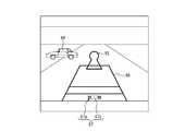
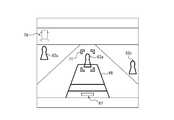
- FIG. 3shows a first example of the detection region 61 in the first video acquired by the image processing device 30 from the imaging device 20.
- the detection area 61is longer in the left-right direction than in the up-down direction.
- the display area 62is located at the center of the detection area 61 in the left-right direction.
- the control unit 33may detect each of the pedestrian 63 and the vehicle 64 reflected inside the display area 62 on the first video as detection targets.
- the control unit 33determines whether one or more conditions are satisfied based on the relative positional relationship between the detection target detected inside the display area 62 on the first video and the moving body 50. judge.
- the one or more conditionsmay include, for example, a first condition that the detection target is located in the first predicted course 65 of the moving body 50.
- the one or more conditionsmay include, for example, a second condition that at least a part of the first predicted course 65 of the moving body 50 overlaps at least a part of the second predicted course to be detected.
- the control unit 33may cause the display device 40 to display a predetermined marker corresponding to the detection target superimposed on the second video.
- the predetermined markermay include a first marker, a second marker, and a third marker.
- control unit 33may determine that the one or more conditions for the pedestrian 63 are satisfied. In such a case, the control unit 33 may display a marker corresponding to the pedestrian 63. The control unit 33 may determine that the one or more conditions for the vehicle 64 are not satisfied. In such a case, the control unit 33 does not display a marker corresponding to the vehicle 64.
- FIG. 4shows an example of the second video corresponding to the display area 62 of the first video shown in FIG.
- the control unit 33cuts out the display area 62 of the first video and then the aspect ratio of the screen of the display device 40.
- the second video that has been deformed according to the abovemay be output to the display device 40.
- a pedestrian 63 and a vehicle 64are shown on the second video.
- the control unit 33may cause the display device 40 to display a guide line 66 indicating at least a part of the first predicted course 65 of the moving body 50 shown in FIG.
- the control unit 33may dynamically change the guide line 66 in accordance with a change in the steering angle of the steering wheel.
- the first videohas a wider range than the display area 62.
- the control unit 33can change the range of the display area 62.
- the control unit 33may superimpose the icon image 67 on the second video and display it on the display device 40.
- the outline 67a of the icon image 67 shown in FIG. 4indicates the maximum range when the range of the display area 62 is changed.
- a white rectangle 67 b of the icon image 67indicates the display area 62.
- An icon image 67 shown in FIG. 4shows the relative position and size of the display area 62 with respect to the maximum range of the display area 62.
- FIG. 5shows an example of a marker superimposed on the pedestrian 63 on the second video, for example.
- the markeris also referred to as a third marker 68.
- the outline 69 of the third marker 68may substantially coincide with the outline of the pedestrian 63 detected on the second video.
- the region 70 inside the contour line 69 of the third marker 68may be filled with a color or pattern corresponding to “person” as the type of detection target, for example.
- the control unit 33may superimpose the third marker 68 on the pedestrian 63 on the second video and display it on the display device 40. According to such a configuration, the target person 60 can easily visually recognize the pedestrian 63 on the second video.
- the control unit 33may hide the third marker 68 when a predetermined time has elapsed since the third marker 68 was displayed.
- FIG. 6shows an example of two types of markers superimposed on the periphery of the pedestrian 63 on the second video, for example.
- each of the two types of markersis also referred to as a first marker 71 and a second marker 72.
- the control unit 33may cause the display device 40 to display the first marker 71 and the second marker 72 superimposed on the second video.
- the control unit 33may move the position of the first marker 71 following the pedestrian 63 on the second video. Since the first marker 71 follows the pedestrian 63, the subject 60 can easily catch the pedestrian 63. The first marker 71 is displayed around the pedestrian 63 away from the pedestrian 63. The subject 60 can easily understand the behavior of the pedestrian 63 when the first marker 71 is displayed on the display device 40.
- the control unit 33may change the overlapping position of the second marker 72 relative to the overlapping position of the first marker 71 on the second video. The control unit 33 may relatively move the second marker with reference to the position of the first marker 71.
- the control unit 33can determine that the contribution of the moving body 50 is large with respect to the decrease in the distance. In such a case, the control unit 33 may move the second marker 72 toward the first marker 71. First, the control unit 33 displays the second marker 72 at a position away from the first marker 71. Next, the control unit 33 moves the second marker 72 toward the first marker 71 until the distance from the first marker 71 becomes a predetermined distance. Next, the control unit 33 erases the second marker 72. Next, the control part 33 displays the 2nd marker 72 in the position away from the 1st marker 71 again, and repeats the above-mentioned process. In this example, the second marker 72 is moving toward an object called the first marker 71. Therefore, the subject 60 can understand that the second marker 72 is approaching the first marker 71.
- the control unit 33can determine that the contribution of the pedestrian 63 to the decrease in the distance is large. In such a case, the control unit 33 may move the second marker 72 away from the first marker 71. First, the control unit 33 displays the second marker 72 at a position close to the first marker 71. Next, the control unit 33 moves the second marker 72 away from the first marker 71 until the distance from the first marker 71 reaches a predetermined distance. Next, the control unit 33 erases the second marker 72. Next, the control unit 33 displays the second marker 72 again at a position close to the first marker 71 and repeats the above-described processing. In this example, the second marker 72 has moved from an object called the first marker 71. For this reason, the subject 60 can understand that the second marker 72 is away from the first marker 71.
- the control unit 33changes the moving direction of the second marker 72 relative to the first marker 71 according to the contribution of the moving body 50 and the pedestrian 63 to the decrease in the distance between the moving body 50 and the pedestrian 63. .
- the subject 60can identify whether the moving body 50 is approaching the pedestrian 63 or whether the pedestrian 63 is approaching the moving body 50 according to the moving direction of the second marker 72, for example.
- the control unit 33may repeatedly enlarge or reduce the second marker 72 around the first marker 71 on the second video.
- the control unit 33may superimpose a first marker 71 and a second marker 72 having the same shape as the outline 69 of the pedestrian 63 on the second video.
- the controller 33may repeat the enlargement or reduction of the second marker 72 around the first marker 71.
- the control unit 33switches the enlargement or reduction of the second marker 72 according to the contribution of the moving body 50 and the pedestrian 63 to the decrease in the distance between the moving body 50 and the pedestrian 63.
- the control unit 33When the distance between the detection target displaying the first marker 71 and the second marker 72 and the moving body 50 is less than a predetermined threshold, the control unit 33 superimposes a new marker on the second video. It's okay.
- the new markeris also referred to as a fourth marker.
- the fourth markermay include an arbitrary image.
- the fourth markermay include an image indicating an exclamation mark “!”. According to such a configuration, for example, when the pedestrian 63 displaying the first marker 71 and the second marker 72 and the moving body 50 approach a certain level or more, the fourth marker is displayed superimposed on the second video. .
- the target person 60can identify that the pedestrian 63 is located in the vicinity of the moving body 50 by the fourth marker, for example.
- the control unit 33when the distance between the detection target displaying the first marker 71 and the second marker 72 and the moving body 50 is less than a predetermined threshold, the control unit 33 performs the first marker
- the display mode of 71 and the second marker 72may be changed.
- the control unit 33may change the colors of the first marker 71 and the second marker 72.
- the control unit 33can detect two detection objects arranged in the depth direction.
- the control unit 33may display the first marker 71 and the second marker 72 on each of the two detection targets located in the front and rear.
- the control unit 33can attach different first markers 71 and second markers 72 to the two detection targets.
- the control unit 33has a first marker 71 that is less conspicuous than the first marker 71 and the second marker 72 that are attached to the second detection target that is positioned on the near side with respect to the first detection target that is positioned on the back side.
- a second marker 72may be attached.
- the control unit 33includes the first marker 71 and the second marker attached to the first detection object located on the back side from the first marker 71 and the second marker 72 attached to the second detection object located on the near side. 72, such as making the color darker, increasing the transmittance, and making the line thinner.
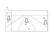
- FIG. 9shows a second example of the detection region 61 in the first video acquired by the image processing device 30 from the imaging device 20.
- the detection area 61is longer in the left-right direction than in the up-down direction.
- the display area 62is located at the center of the detection area 61 in the left-right direction.
- the control unit 33includes a pedestrian 63a reflected inside the display area 62 on the first video, and pedestrians 63b and 63c reflected outside the display area 62 and inside the detection area 61, respectively. You may detect as a detection target.
- the process of the control part 33 regarding the pedestrian 63ais the same as the process regarding the pedestrian 63 shown, for example in FIG.
- the control unit 33displays a marker corresponding to the detection target superimposed on the second video. It may be displayed on the device 40.
- the markeris also referred to as a fifth marker.
- the control unit 33may display the fifth marker when it is determined that there is a possibility that the moving body 50 and the detection target are in contact with each other.
- the control unit 33superimposes the fifth marker on the right end of the second video on the display device 40. You may display.
- the control unit 33superimposes the fifth marker on the left end of the second video on the display device 40. You may display.
- the detection position where the pedestrian 63b is detectedis on the right side of the display area 62.
- the control unit 33may determine the possibility that the moving body 50 and the pedestrian 63b come into contact based on the distance between the moving body 50 and the pedestrian 63b and the decreasing speed of the distance.
- the control unit 33may determine that there is a possibility that the moving body 50 and the pedestrian 63b are in contact with each other. In such a case, the control unit 33 may cause the display device 40 to display the fifth marker corresponding to the pedestrian 63b superimposed on the right end of the second video. Details of the fifth marker corresponding to the pedestrian 63b will be described later.
- the detection position where the pedestrian 63 c is detectedis on the left side of the display area 62.
- control unit 33may determine the possibility that the moving body 50 and the pedestrian 63c come into contact based on the distance between the moving body 50 and the pedestrian 63c and the decreasing speed of the distance. For example, the control unit 33 may determine that there is no possibility that the moving body 50 and the pedestrian 63c come into contact. In such a case, the control unit 33 may not display the fifth marker corresponding to the pedestrian 63b.
- FIG. 10shows an example of the second video corresponding to the display area 62 of the first video shown in FIG. As shown in FIG. 10, a pedestrian 63a is shown on the second video. Pedestrians 63b and 63c are not shown on the second video.
- the control unit 33may display an obstacle image 74 on the display device 40 by superimposing the obstacle image 74 on the second video, for example.
- the obstacle image 74shows the detection result of the obstacle detection apparatus using the ultrasonic sonar provided in the moving body 50.
- the obstacle image 74may include an image 74a, an image 74b, and an image 74c.
- the image 74ais an image in which the moving body 50 is viewed from above.
- the image 74 bis an image indicating that an obstacle is detected on the left rear side of the moving body 50.
- the image 74 cis an image indicating that an obstacle has been detected on the right rear side of the moving body 50.
- the detection result of the obstacle by the obstacle detection device and the detection result of the detection target by the control unit 33do not necessarily match.
- the obstacle image 74indicates that obstacles are detected at the right rear and the left rear of the moving body 50.
- the control unit 33can determine that there is no possibility that the pedestrian 63 c existing on the left rear side of the moving body 50 is in contact with the moving body 50. In such a case, the control unit 33 may not display the fifth marker corresponding to the pedestrian 63c.
- the fifth marker 73may include an icon image 73a and a band image 73b.
- the icon image 73amay be an image corresponding to “person” which is the type of detection target.
- the subject 60 who has visually recognized the icon image 73acan recognize that a person is present on the right side of the second video.
- the band image 73bis, for example, a band-shaped image extending in the vertical direction on the second video.
- the band image 73bmay be filled with a color or pattern corresponding to, for example, “person” as the type of detection target.
- the control unit 33may move the band image 73b in the right end region 73c on the second video.
- the control unit 33may change the moving speed and width of the band image 73b.
- the control unit 33may determine the width of the band image 73b according to the distance between the moving body 50 and the pedestrian 63b. For example, the control unit 33 may increase the width of the band image 73b as the distance approaches. The subject 60 who has visually recognized the band image 73b can recognize the distance between the moving body 50 and the pedestrian 63b based on the width of the band image 73b.
- the control unit 33can determine that the contribution of the moving body 50 is large, for example, with respect to the decrease in the distance between the moving body 50 and the pedestrian 63b. In such a case, the control unit 33 repeatedly moves the band image 73b in the first direction within the right end region 73c on the second video.
- the first directionmay be a direction from the outside toward the inside in the left-right direction on the second video.
- the control unit 33can determine that, for example, the contribution of the pedestrian 63b is large with respect to the decrease in the distance between the moving body 50 and the pedestrian 63b. In such a case, the control unit 33 repeatedly moves the band image 73b in the second direction within the right end region 73c on the second video.
- the second directionmay be, for example, a direction from the inside toward the outside in the left-right direction on the second video.
- the subject 60 who visually recognizes the band image 73bcan recognize whether the moving body 50 is approaching the pedestrian 63b or whether the pedestrian 63b is approaching the moving body 50 based on the moving direction of the band image 73b. It is.
- the control unit 33may determine the moving speed of the band image 73b according to the decreasing speed of the distance between the moving body 50 and the pedestrian 63b. For example, the moving speed of the band image 73b may be increased as the decreasing speed of the distance is faster. The subject 60 who has visually recognized the band image 73b can recognize the decreasing speed of the distance between the moving body 50 and the pedestrian 63b based on the moving speed of the band image 73b.
- the control unit 33detects a user input corresponding to a predetermined user operation in a state where the fifth marker 73 is displayed, the detection position of the pedestrian 63b on the first video is included inside the display region 62.
- the display area 62may be changed as described above. For example, as shown in FIG. 11, the control unit 33 may lengthen the display area 62 on the first video image in the left-right direction and move the display area 62 to the right side in the detection area 61. With such a configuration, for example, as shown in FIG. 12, a pedestrian 63b appears on the second video.
- the predetermined user operation described abovemay include an arbitrary user operation.
- the predetermined user operation described abovemay include a first user operation that changes the steering angle of the moving body 50.
- the fifth marker 73may function as a GUI (Graphic User Interface) that receives the second user operation.
- GUIGraphic User Interface
- the GUIis also referred to as an interface image.
- the predetermined user operation described abovemay include a second user operation.
- the control unit 33may automatically change the display area 62 such that the detection position of the pedestrian 63b on the first video is included inside the display area 62. In this case, the control unit 33 can maintain the automatic change of the display area 62 until the pedestrian 63b is not detected in the detection area 61 of the first video.
- the control unit 33may change the icon image 67 in accordance with the change in the display area 62, for example, as shown in FIG.
- the control unit 33may change the display area 62 on the first video according to, for example, a pinch-in operation and a pinch-out operation on the display device 40. For example, as shown in FIG. 13, the control unit 33 may make the display area 62 substantially coincide with the detection area 61. In such a case, for example, as shown in FIG. 14, all detection targets in the detection area 61 are displayed on the display device 40.
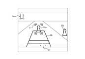
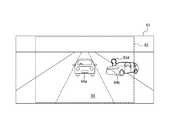
- FIG. 15shows a third example of the detection region 61 in the first video acquired by the image processing device 30 from the imaging device 20.
- the detection area 61is longer in the left-right direction than in the up-down direction.
- the display area 62is located at the center of the detection area 61 in the left-right direction.
- the control unit 33may detect the vehicle 64a shown in the first predicted course 65 of the moving body 50, the vehicle 64b shown outside the first predicted course 65, and the pedestrian 63d as detection targets. .
- the characteristic values of the first video and the second videomay be reduced.
- the characteristic valuemay include an arbitrary parameter related to video visibility.
- the characteristic valuemay include at least one of, for example, a luminance value of a video and a contrast ratio.
- the characteristic value of the second videois lowered, the visibility of the second video can be lowered.
- the control unit 33may execute specific image processing on the area corresponding to the detection target on the second video.
- the specific image processingmay include first processing for superimposing a marker corresponding to the detection target on the region.
- the markeris also referred to as a sixth marker.
- the sixth markermay include an image that substantially matches the contour shape of the detection target on the second video. According to this configuration, the sixth marker is superimposed and displayed on the detection target on the second video. Therefore, the target person 60 can easily recognize the detection target on the second video even when the characteristic value of the second video is low.
- the specific image processingmay include second processing for changing the characteristic value of the region corresponding to the detection target on the second video.
- control unit 33may change the characteristic value of the region so as to improve the visibility of the region on the second video. According to such a configuration, the visibility of the detection target on the second video is improved. Therefore, the target person 60 can easily recognize the detection target on the second video even when the characteristic value of the second video is low.
- the control unit 33may execute the above-described specific image processing when one or more conditions are satisfied.
- the one or more conditionsmay include a condition that the detection target is located in the first predicted course 65 of the moving body 50.
- the one or more conditionsmay include a condition that the first predicted course 65 of the moving body 50 and the second predicted course to be detected overlap.
- the one or more conditionsmay include a condition that the distance between the moving body 50 and the detection target is less than a predetermined threshold.
- the one or more conditionsmay include a condition that a characteristic value of at least a part of the second video is less than a predetermined threshold.
- the control unit 33may determine that one or more conditions described above are satisfied for each of the vehicles 64a and 64b and the pedestrian 63d. In such a case, for example, as shown in FIG. 16, the control unit 33 displays three sixth markers 75a, 75b, and 75c corresponding to the vehicles 64a and 64b and the pedestrian 63d, respectively, superimposed on the second video. It may be displayed on the device 40. The control unit 33 may display the sixth marker superimposed on the detection target in a bright place.
- the control unit 33may change the shape of the guide line 66.
- the control unit 33may change the shape of the guide line 66 in a region where the guide line 66 and the detection target overlap.
- FIG. 17shows one example of the shape of the guide line 66.
- the guide lineis not displayed in the area
- An example of the shape of the guide line 66is not limited to erasing, but allows other design changes.
- the design changeincludes a color change, a transmittance change, a type change to a broken line, a line thickness change, a blinking, and the like.
- the control unit 33may change the shape of the guide line 66 when the sixth marker is not displayed.
- the control unit 33may change the shape of the guide line 66 when the first marker 71 and the second marker 72 are displayed on the detection target.
- various markers corresponding to the detection target detected on the first videoare displayed on the display device 40 while being superimposed on the second video.
- the target person 60 who visually recognizes the markercan recognize the relative positional relationship between the moving body 50 and the detection target at a glance. For this reason, the convenience of the technique which displays the image
- each component and function of the display system 10may be rearranged.
- part or all of the configuration and functions of the image processing device 30may be included in at least one of the imaging device 20 and the display device 40.
- the image processing device 30 or the likemay be realized as a communication device such as a mobile phone or an external server, and may be connected to other components of the display system 10 by wire or wireless.
Landscapes
- Engineering & Computer Science (AREA)
- Physics & Mathematics (AREA)
- General Physics & Mathematics (AREA)
- Theoretical Computer Science (AREA)
- Multimedia (AREA)
- Computer Vision & Pattern Recognition (AREA)
- Signal Processing (AREA)
- Closed-Circuit Television Systems (AREA)
- Studio Devices (AREA)
Abstract
Description
Translated fromJapanese本出願は、2016年11月21日に日本国に特許出願された特願2016-226332、特願2016-226333、特願2016-226334、および特願2016-226336の優先権を主張するものであり、これらの先の出願の開示全体をここに参照のために取り込む。This application claims the priority of Japanese Patent Application Nos. 2016-226332, 2016-226333, 2016-226334, and 2016-226336 filed on November 21, 2016 in Japan. And the entire disclosures of these earlier applications are incorporated herein by reference.
本開示は、画像処理装置、撮像装置、および表示システムに関する。The present disclosure relates to an image processing device, an imaging device, and a display system.
従来、例えば車両等の移動体の外部領域の映像を表示する技術が知られている。例えば、特許文献1には、車両に備えられたカメラの映像を表示するモニタへの電源供給を制御する技術が開示されている。Conventionally, a technique for displaying an image of an external area of a moving body such as a vehicle is known. For example, Patent Literature 1 discloses a technique for controlling power supply to a monitor that displays an image of a camera provided in a vehicle.
本開示の一実施形態に係る画像処理装置は、通信部と、制御部と、を備える。通信部は、移動体の外部領域を撮像した第1映像を取得する。制御部は、第1映像上の表示領域に対応する第2映像を表示装置に表示させる。制御部は、第1映像上の表示領域において検出対象の少なくとも一部を検出し、移動体および検出対象の相対的位置関係に基づいて、1つ以上の条件が満たされるか否かを判定し、1つ以上の条件が満たされると判定された場合、検出対象に対応する第1マーカ71を、第2映像に重畳して表示装置に表示させる。An image processing apparatus according to an embodiment of the present disclosure includes a communication unit and a control unit. A communication part acquires the 1st image | video which imaged the external area | region of the moving body. The control unit causes the display device to display the second video corresponding to the display area on the first video. The control unit detects at least a part of the detection target in the display area on the first video, and determines whether one or more conditions are satisfied based on a relative positional relationship between the moving object and the detection target. When it is determined that one or more conditions are satisfied, the
本開示の一実施形態に係る撮像装置は、撮像素子と、制御部と、を備える。撮像素子は、移動体の外部領域を撮像した第1映像を生成する。制御部は、第1映像上の表示領域に対応する第2映像を表示装置に表示させる。制御部は、第1映像上の表示領域において検出対象の少なくとも一部を検出し、移動体および検出対象の相対的位置関係に基づいて、1つ以上の条件が満たされるか否かを判定し、1つ以上の条件が満たされると判定された場合、検出対象に対応する第1マーカを、第2映像に重畳して表示装置に表示させる。An imaging apparatus according to an embodiment of the present disclosure includes an imaging element and a control unit. The imaging device generates a first video that images an external region of the moving body. The control unit causes the display device to display the second video corresponding to the display area on the first video. The control unit detects at least a part of the detection target in the display area on the first video, and determines whether one or more conditions are satisfied based on a relative positional relationship between the moving object and the detection target. When it is determined that one or more conditions are satisfied, the first marker corresponding to the detection target is superimposed on the second video and displayed on the display device.
本開示の一実施形態に係る表示システムは、表示装置と、撮像装置と、画像処理装置と、を備える。撮像装置は、移動体の外部領域を撮像した第1映像を生成する。画像処理装置は、第1映像上の表示領域に対応する第2映像を表示装置に表示させる。画像処理装置は、第1映像上の表示領域において検出対象の少なくとも一部を検出し、移動体および検出対象の相対的位置関係に基づいて、1つ以上の条件が満たされるか否かを判定し、1つ以上の条件が満たされると判定された場合、検出対象に対応する第1マーカを、第2映像に重畳して前記表示装置に表示させる。A display system according to an embodiment of the present disclosure includes a display device, an imaging device, and an image processing device. An imaging device produces | generates the 1st image | video which imaged the external area | region of the moving body. The image processing device causes the display device to display the second video corresponding to the display area on the first video. The image processing apparatus detects at least a part of the detection target in the display area on the first video, and determines whether one or more conditions are satisfied based on a relative positional relationship between the moving object and the detection target. And when it determines with one or more conditions being satisfy | filled, the 1st marker corresponding to a detection target is superimposed on a 2nd image | video, and is displayed on the said display apparatus.
本開示の一実施形態に係る画像処理装置は、通信部と、制御部と、を備える。通信部は、移動体の外部領域を撮像した第1映像を取得する。制御部は、第1映像上の表示領域に対応する第2映像を表示装置に表示させる。制御部は、第1映像上の表示領域において検出対象の少なくとも一部を検出し、第2映像上の検出対象の少なくとも一部に対応する領域に対して特定画像処理を実行する。An image processing apparatus according to an embodiment of the present disclosure includes a communication unit and a control unit. A communication part acquires the 1st image | video which imaged the external area | region of the moving body. The control unit causes the display device to display the second video corresponding to the display area on the first video. The control unit detects at least a part of the detection target in the display area on the first video, and executes specific image processing on an area corresponding to at least a part of the detection target on the second video.
本開示の一実施形態に係る撮像装置は、撮像素子と、制御部と、を備える。撮像素子は、移動体の外部領域を撮像した第1映像を生成する。制御部は、第1映像上の表示領域に対応する第2映像を表示装置に表示させる。制御部は、第1映像上の表示領域において検出対象の少なくとも一部を検出し、第2映像上の検出対象の少なくとも一部に対応する領域に対して特定画像処理を実行する。An imaging apparatus according to an embodiment of the present disclosure includes an imaging element and a control unit. The imaging device generates a first video that images an external region of the moving body. The control unit causes the display device to display the second video corresponding to the display area on the first video. The control unit detects at least a part of the detection target in the display area on the first video, and executes specific image processing on an area corresponding to at least a part of the detection target on the second video.
本開示の一実施形態に係る表示システムは、表示装置と、撮像装置と、画像処理装置と、を備える。撮像装置は、移動体の外部領域を撮像した第1映像を生成する。画像処理装置は、第1映像上の表示領域に対応する第2映像を表示装置に表示させる。画像処理装置は、第1映像上の表示領域において検出対象の少なくとも一部を検出し、第2映像上の検出対象の少なくとも一部に対応する領域に対して特定画像処理を実行する。A display system according to an embodiment of the present disclosure includes a display device, an imaging device, and an image processing device. An imaging device produces | generates the 1st image | video which imaged the external area | region of the moving body. The image processing device causes the display device to display the second video corresponding to the display area on the first video. The image processing device detects at least a part of the detection target in the display area on the first video, and executes specific image processing on an area corresponding to at least a part of the detection target on the second video.
本開示の一実施形態に係る画像処理装置は、通信部と、制御部と、を備える。通信部は、移動体の外部領域を撮像した第1映像を取得する。制御部は、第1映像上の表示領域に対応する第2映像を表示装置に表示させる。制御部は、第1映像上の検出領域において検出対象の少なくとも一部を検出し、検出対象の前記少なくとも一部が検出された第1映像上の検出位置が、表示領域の外側且つ検出領域の内側にある場合、検出対象に対応するマーカを、第2映像に重畳して表示装置に表示させる。An image processing apparatus according to an embodiment of the present disclosure includes a communication unit and a control unit. A communication part acquires the 1st image | video which imaged the external area | region of the moving body. The control unit causes the display device to display the second video corresponding to the display area on the first video. The control unit detects at least a part of the detection target in the detection region on the first video, and the detection position on the first video where the at least part of the detection target is detected is outside the display region and the detection region. If it is inside, the marker corresponding to the detection target is displayed on the display device so as to be superimposed on the second video.
本開示の一実施形態に係る撮像装置は、撮像素子と、制御部と、を備える。撮像素子は、移動体の外部領域を撮像した第1映像を生成する。制御部は、第1映像上の表示領域に対応する第2映像を表示装置に表示させる。制御部は、第1映像上の検出領域において検出対象の少なくとも一部を検出し、検出対象の少なくとも一部が検出された第1映像上の検出位置が、表示領域の外側且つ検出領域の内側にある場合、検出対象に対応するマーカを、第2映像に重畳して表示装置に表示させる。An imaging apparatus according to an embodiment of the present disclosure includes an imaging element and a control unit. The imaging device generates a first video that images an external region of the moving body. The control unit causes the display device to display the second video corresponding to the display area on the first video. The control unit detects at least a part of the detection target in the detection region on the first video, and the detection position on the first video where at least a part of the detection target is detected is outside the display region and inside the detection region If so, the marker corresponding to the detection target is superimposed on the second video and displayed on the display device.
本開示の一実施形態に係る表示システムは、表示装置と、撮像装置と、画像処理装置と、を備える。撮像装置は、移動体の外部領域を撮像した第1映像を生成する。画像処理装置は、第1映像上の表示領域に対応する第2映像を表示装置に表示させる。画像処理装置は、第1映像上の検出領域において検出対象の少なくとも一部を検出し、検出対象の少なくとも一部が検出された第1映像上の検出位置が、表示領域の外側且つ検出領域の内側にある場合、検出対象に対応するマーカを、第2映像に重畳して表示装置に表示させる。A display system according to an embodiment of the present disclosure includes a display device, an imaging device, and an image processing device. An imaging device produces | generates the 1st image | video which imaged the external area | region of the moving body. The image processing device causes the display device to display the second video corresponding to the display area on the first video. The image processing apparatus detects at least a part of the detection target in the detection region on the first video, and the detection position on the first video from which at least a part of the detection target is detected is outside the display region and the detection region. If it is inside, the marker corresponding to the detection target is displayed on the display device so as to be superimposed on the second video.
本開示の一実施形態に係る画像処理装置は、通信部と、制御部と、を備える。通信部は、移動体の外部領域を撮像した第1映像を取得する。制御部は、第1映像上の表示領域に対応する第2映像を表示装置に表示させる。制御部は、第1映像上の検出領域において検出対象の少なくとも一部を検出し、検出対象の少なくとも一部が検出された第1映像上の検出位置が、表示領域の外側且つ検出領域の内側にある場合、検出位置が表示領域の内側に含まれるように表示領域を変化させる。An image processing apparatus according to an embodiment of the present disclosure includes a communication unit and a control unit. A communication part acquires the 1st image | video which imaged the external area | region of the moving body. The control unit causes the display device to display the second video corresponding to the display area on the first video. The control unit detects at least a part of the detection target in the detection region on the first video, and the detection position on the first video where at least a part of the detection target is detected is outside the display region and inside the detection region The display area is changed so that the detection position is included inside the display area.
本開示の一実施形態に係る撮像装置は、撮像素子と、制御部と、を備える。撮像素子は、移動体の外部領域を撮像した第1映像を生成する。制御部は、第1映像上の表示領域に対応する第2映像を表示装置に表示させる。制御部は、第1映像上の検出領域において検出対象の少なくとも一部を検出し、検出対象の少なくとも一部が検出された第1映像上の検出位置が、表示領域の外側且つ検出領域の内側にある場合、検出位置が表示領域の内側に含まれるように表示領域を変化させる。An imaging apparatus according to an embodiment of the present disclosure includes an imaging element and a control unit. The imaging device generates a first video that images an external region of the moving body. The control unit causes the display device to display the second video corresponding to the display area on the first video. The control unit detects at least a part of the detection target in the detection region on the first video, and the detection position on the first video where at least a part of the detection target is detected is outside the display region and inside the detection region The display area is changed so that the detection position is included inside the display area.
本開示の一実施形態に係る表示システムは、表示装置と、撮像装置と、画像処理装置と、を備える。撮像装置は、移動体の外部領域を撮像した第1映像を生成する。画像処理装置は、第1映像上の表示領域に対応する第2映像を表示装置に表示させる。画像処理装置は、第1映像上の検出領域において検出対象の少なくとも一部を検出し、検出対象の少なくとも一部が検出された第1映像上の検出位置が、表示領域の外側且つ検出領域の内側にある場合、検出位置が表示領域の内側に含まれるように表示領域を変化させる。A display system according to an embodiment of the present disclosure includes a display device, an imaging device, and an image processing device. An imaging device produces | generates the 1st image | video which imaged the external area | region of the moving body. The image processing device causes the display device to display the second video corresponding to the display area on the first video. The image processing apparatus detects at least a part of the detection target in the detection region on the first video, and the detection position on the first video from which at least a part of the detection target is detected is outside the display region and the detection region. If it is inside, the display area is changed so that the detection position is included inside the display area.
従来、移動体の外部領域の映像を表示する技術について改善の余地があった。本開示は、移動体の外部領域の映像を表示する技術の利便性を向上させる画像処理装置、撮像装置、および表示システムに関する。本開示の一実施形態に係る画像処理装置、撮像装置、および表示システムよれば、移動体の外部領域の映像を表示する技術の利便性が向上する。以下、本開示の実施形態について、図面を参照して説明する。Previously, there was room for improvement in the technology for displaying images of the external area of the moving body. The present disclosure relates to an image processing device, an imaging device, and a display system that improve the convenience of a technique for displaying an image of an external area of a moving object. According to the image processing device, the imaging device, and the display system according to an embodiment of the present disclosure, the convenience of a technique for displaying an image of an external area of a moving body is improved. Hereinafter, embodiments of the present disclosure will be described with reference to the drawings.
(表示システム)
図1を参照して、本開示の一実施形態に係る表示システム10について説明する。(Display system)
A
図1に示すように、表示システム10は、撮像装置20と、画像処理装置30と、表示装置40と、を備える。表示システム10の各構成要素は、例えばネットワーク51を介して情報を送受信可能である。ネットワーク51は、例えば無線、有線、またはCAN(Controller Area Network)等を含んでよい。As shown in FIG. 1, the
他の実施形態において、表示システム10の一部または全部の構成要素が、1つの装置として一体的に構成されてよい。例えば、撮像装置20または表示装置40に、画像処理装置30を内蔵させる構成等が考えられる。In other embodiments, some or all of the components of the
図2に示すように、撮像装置20、画像処理装置30、および表示装置40は、移動体50に備えられてよい。本開示における「移動体」は、例えば車両、船舶、および航空機等を含んでよい。車両は、例えば自動車、産業車両、鉄道車両、生活車両、および滑走路を走行する固定翼機等を含んでよい。自動車は、例えば乗用車、トラック、バス、二輪車、およびトロリーバス等を含んでよい。産業車両は、例えば農業および建設向けの産業車両等を含んでよい。産業車両は、例えばフォークリフトおよびゴルフカート等を含んでよい。農業向けの産業車両は、例えばトラクター、耕耘機、移植機、バインダー、コンバイン、および芝刈り機等を含んでよい。建設向けの産業車両は、例えばブルドーザー、スクレーバー、ショベルカー、クレーン車、ダンプカー、およびロードローラ等を含んでよい。車両は、人力で走行するものを含んでよい。車両の分類は、上述した例に限られない。例えば、自動車は、道路を走行可能な産業車両を含んでよい。複数の分類に同じ車両が含まれてよい。船舶は、例えばマリンジェット、ボート、およびタンカー等を含んでよい。航空機は、例えば固定翼機および回転翼機等を含んでよい。As shown in FIG. 2, the
撮像装置20は、移動体50の外部領域を撮像可能である。撮像装置20の位置は、移動体50の内部および外部において任意である。例えば図2に示すように、撮像装置20は、移動体50の後方の外部領域を撮像可能な移動体50の後方に位置する。画像処理装置30の位置は、移動体50内において任意である。表示装置40は、対象者60によって視認可能である。表示装置40の位置は、移動体50において任意である。例えば図2に示すように、表示装置40は、移動体50のダッシュボードの中に位置する。The
(撮像装置)
撮像装置20について詳細に説明する。例えば図1に示すように、撮像装置20は、撮像光学系21と、撮像素子22と、通信部23と、制御部24とを備える。(Imaging device)
The
撮像光学系21は、被写体像を結像させる。例えば、撮像光学系21は、絞りおよび1つ以上のレンズを含んでよい。The imaging
撮像素子22は、2次元配列された複数の画素を有する。撮像素子22は、例えばCCD(Charge Coupled Device)撮像素子またはCMOS(Complementary Metal Oxide Semiconductor)撮像素子を含んでよい。撮像素子22は、撮像光学系21によって結像される被写体像を撮像して、撮像画像を生成可能である。The
通信部23は、外部装置と通信可能な通信インタフェースを含んでよい。通信部23は、ネットワーク51を介して情報の送受信が可能であってよい。外部装置は、例えば画像処理装置30を含んでよい。本開示における「通信インタフェース」は、例えば物理コネクタ、および無線通信機を含んでよい。物理コネクタは、電気信号による伝送に対応した電気コネクタ、光信号による伝送に対応した光コネクタ、および電磁波による伝送に対応した電磁コネクタを含んでよい。電気コネクタは、IEC60603に準拠するコネクタ、USB規格に準拠するコネクタ、RCA端子に対応するコネクタ、EIAJ CP-1211Aに規定されるS端子に対応するコネクタ、EIAJ RC-5237に規定されるD端子に対応するコネクタ、HDMI(登録商標)規格に準拠するコネクタ、およびBNC(British Naval ConnectorまたはBaby-series N Connector等)を含む同軸ケーブルに対応するコネクタを含んでよい。光コネクタは、IEC 61754に準拠する種々のコネクタを含んでよい。無線通信機は、Bluetooth(登録商標)、およびIEEE802.11を含む各規格に準拠する無線通信機を含んでよい。無線通信機は、少なくとも1つのアンテナを含む。The
制御部24は、1つ以上のプロセッサを含む。本開示における「プロセッサ」は、特定の処理に特化した専用のプロセッサ、および特定のプログラムを読み込むことによって特定の機能を実行する汎用のプロセッサを含んでよい。専用のプロセッサには、DSP(Digital Signal Processor)および特定用途向けIC(ASIC;Application Specific Integrated Circuit)が含まれてよい。プロセッサには、プログラマブルロジックデバイス(PLD;Programmable Logic Device)が含まれてよい。PLDには、FPGA(Field-Programmable Gate Array)が含まれてよい。制御部24は、1つまたは複数のプロセッサが協働するSoC(System-on-a-Chip)、およびSiP(System In a Package)のいずれかであってよい。The
制御部24は、撮像装置20全体の動作を制御する。制御部24は、任意のフレームレートで、撮像素子22に撮像画像を生成させてよい。当該フレームレートは、例えば、表示装置40が表示可能なフレームレートに略一致してよい。制御部24は、生成された撮像画像に対して、所定の画像処理を実行してよい。当該画像処理は、例えば露出調整処理、ホワイトバランス処理、および歪み補正処理等を含んでよい。制御部24は、通信部23を介して画像処理装置30へ、撮像画像を出力する。例えば、制御部24は、上述のフレームレートで撮像画像を順次に出力してよい。以下、上述のフレームレートで出力される各撮像画像を、単にフレームともいう。撮像装置20から出力される当該複数の撮像画像を、第1映像ともいう。例えばフレームレートが60fps(Flame per Seconds)である場合、1秒あたり60枚の撮像画像が第1映像として出力される。The
(画像処理装置)
画像処理装置30について詳細に説明する。画像処理装置30は、通信部31と、記憶部32と、制御部33とを備える。(Image processing device)
The
通信部31は、多様な外部装置と通信可能な通信インタフェースを含んでよい。外部装置は、例えば撮像装置20、表示装置40、移動体50に備えられたECU(Electronic Control UnitまたはEngine Control unit)、速度センサ、加速度センサ、回転角センサ、ステアリング舵角センサ、エンジン回転数センサ、アクセルセンサ、ブレーキセンサ、照度センサ、雨滴センサ、走行距離センサ、ミリ波レーダ、超音波ソナー等を用いた障害物検出装置、ETC(Electronic Toll Collection System)受信装置、GPS(Global Positioning System)装置、ナビゲーション装置、インターネット上のサーバ、携帯電話等を含んでよい。The
通信部31は、歩車間通信、路車間通信および車車間通信のための通信インタフェースを含んでよい。通信部31は、日本において提供されるDSRC(Dedicated Short-Range Communication:狭帯域通信システム)およびVICS(登録商標)(Vehicle Information and Communication System)の光ビーコンに対応した受信機を含んでよい。通信部31は、他の国の道路交通情報提供システムに対応した受信機を含んでよい。The
通信部31は、外部装置から多様な情報を取得可能であってよい。例えば、通信部31は、移動体情報および環境情報を取得可能であってよい。The
移動体情報は、移動体50に関する任意の情報を含んでよい。移動体情報は、例えば移動体50の速度、加速度、旋回重力、傾き、方角、および旋回状況、ステアリングホイールの舵角、冷却水の温度、燃料の残量、バッテリの残量、バッテリの電圧、エンジン回転数、ギアポジション、リバース信号の有無、アクセル操作の有無、アクセル開度、ブレーキ操作の有無、ブレーキ踏度、パーキングブレーキの作動有無、前後輪もしくは4輪の回転数差、タイヤ空気圧、ダンパの伸縮量、運転手の目の空間位置、乗員の数および座席位置、シートベルトの装着情報、ドアの開閉、窓の開閉、車内温度、空調の動作有無、空調の設定温度、空調の送風量、外気循環の設定、ワイパーの作動状況、走行モード、外部機器との接続情報、現在時刻、平均燃費、瞬間燃費、各種ランプの点灯状態、移動体50の位置情報、ならびに移動体50の目的地までの経路情報等を含んでよい。各種ランプは、例えばヘッドランプ、フォグランプ、バックランプ、ポジションランプ、およびターンシグナルを含んでよい。The moving body information may include arbitrary information regarding the moving
環境情報は、移動体50の外部環境に関する任意の情報を含んでよい。環境情報は、例えば移動体50の周囲の明るさ、天気、気圧、外気温度、地図情報、交通情報、道路工事情報、走行路の制限速度の一時的な変更、他の車両が検出した対象物、および信号機の点灯状態等を含んでよい。The environment information may include arbitrary information related to the external environment of the
記憶部32は、一時記憶装置および二次記憶装置を含んでよい。記憶部32は、例えば半導体メモリ、磁気メモリ、および光メモリ等を用いて構成されてよい。半導体メモリは、揮発性メモリおよび不揮発性メモリを含んでよい。磁気メモリは、例えばハードディスクおよび磁気テープ等を含んでよい。光メモリは、例えばCD(Compact Disc)、DVD(Digital Versatile Disc)、およびBD(登録商標)(Blu-ray(登録商標) Disc)等を含んでよい。記憶部32は、画像処理装置30の動作に必要な種々の情報およびプログラムを記憶する。The
制御部33は、1つ以上のプロセッサを含む。制御部33は、画像処理装置30全体の動作を制御する。The
制御部33は、通信部31を介して外部装置から、移動体情報および環境情報を取得してよい。制御部33は、例えば移動体情報に基づいて、移動体50の予測進路を決定してよい。以下、移動体50の予測進路を、第1予測進路ともいう。The
制御部33は、通信部31を介して撮像装置20から、第1映像を取得してよい。第1映像は、検出領域と表示領域とを含む。The
制御部33は、取得された第1映像上の検出領域内において、検出対象の少なくとも一部を検出してよい。第1映像上の検出領域は、第1映像の各フレームである撮像画像上の少なくとも一部の領域であってよい。第1映像の各フレームは、撮像画像と呼び得る。第1映像上の検出領域は、表示領域より大きくてよい。第1映像上の検出領域は、表示領域を包含してよい。制御部33は、表示領域の内側において検出対象を検出し得る。制御部33は、表示領域の外側であって検出領域の内側において、検出対象を検出し得る。検出領域および表示領域の内側の領域は、第1領域と呼び得る。検出領域の内側であって表示領域の外側の領域は、第2領域と呼び得る。The
検出対象は、複数の種類の物体を含んでよい。物体の種類は、例えば人、他の移動体、走行路、車線、白線、側溝、歩道、横断歩道、道路標識、交通標識、ガードレール、壁、および信号機等を含んでよい。制御部33が検出可能な検出対象の種類は、これらに限られない。検出対象の少なくとも一部は、例えば第1映像上の検出対象の一部が他の物体の陰に隠れている場合において、当該検出対象の、当該他の物体の陰に隠れていない部分を含んでよい。例えば、制御部33は、第1映像上で歩行者の下半身が障害物の陰に隠れている場合に、当該歩行者の上半身を検出可能であってよい。検出対象の少なくとも一部の検出には、任意の物体検出アルゴリズムが採用可能であってよい。例えば、制御部33は、第1映像の各フレームである撮像画像を用いたパターンマッチングまたは特徴点抽出等のアルゴリズムによって、検出対象の少なくとも一部を検出してよい。The detection target may include a plurality of types of objects. The types of objects may include, for example, people, other moving objects, lanes, lanes, white lines, gutters, sidewalks, crosswalks, road signs, traffic signs, guardrails, walls, traffic lights, and the like. The types of detection targets that can be detected by the
制御部33は、第1映像上で検出対象の少なくとも一部が検出されると、第1映像に基づいて、当該検出対象の予測進路を決定してよい。以下、検出対象の予測進路を、第2予測進路ともいう。第2予測進路の決定には、任意のアルゴリズムが採用可能であってよい。例えば、制御部33は、第1映像の各フレームである撮像画像上の、検出対象の向きおよび位置の変化に基づいて、第2予測進路を決定してよい。When at least a part of the detection target is detected on the first video, the
制御部33は、第1映像上で検出対象の少なくとも一部が検出されると、第1映像に基づいて、移動体50および当該検出対象の相対的位置関係を推定してよい。相対的位置関係は、例えば移動体50と検出対象との間の距離、および、移動体50の第1予測進路と検出対象の第2予測進路との重なりの有無等を含んでよい。移動体50と検出対象との間の距離の推定には、任意のアルゴリズムが採用可能であってよい。例えば、制御部33は、第1映像信号の各フレームである撮像画像を用いて、モーションステレオ法によって、移動体50と検出対象との間の距離を推定してよい。他の実施形態において、制御部33は、通信部31を介して外部装置から、移動体50および当該検出対象の相対的位置関係を示す情報を取得してよい。The
制御部33は、移動体50と検出対象との間の距離が減少する場合、当該距離の減少に対して移動体50と検出対象との何れの寄与が大きいかを判定してよい。当該距離の減少に対する移動体50および検出対象の寄与の決定には、任意のアルゴリズムが採用可能であってよい。一例において、制御部33は、移動体情報に基づいて、移動体50の移動速度を検出してよい。制御部33は、例えば第1映像の各フレームである撮像画像上の検出対象の位置の変化に基づいて、当該検出対象の移動速度を検出してよい。制御部33は、当該距離の減少に対して、移動体50および検出対象のうち何れか移動速度が大きい一方の寄与が大きいと判定してよい。他の例において、制御部33は、移動体50の移動速度が基準値未満である場合、当該距離の減少に対して検出対象の寄与が大きいと判定してよい。制御部33は、移動体50の移動速度が基準値以上である場合、当該距離の減少に対して移動体50の寄与が大きいと判定してよい。当該基準値は、任意に定められてよいが、例えば略ゼロに定められてよい。当該距離の減少に対する移動体50および検出対象の寄与に応じた画像処理装置30の動作の詳細については後述する。When the distance between the moving
制御部33は、第1映像上で検出対象の少なくとも一部が検出されると、第1映像に基づいて、移動体50と当該検出対象とが接触する可能性があるか否かを判定してよい。移動体50と検出対象とが接触する可能性の決定には、任意のアルゴリズムが採用可能であってよい。例えば、制御部33は、移動体50と検出対象との間の距離が所定の閾値未満であるとの条件、および、当該距離の減少速度が所定の閾値以上であるとの条件の少なくとも一方が満たされる場合、移動体50と検出対象とが接触する可能性があると判定してよい。当該可能性の有無に応じた画像処理装置30の動作の詳細については後述する。When at least a part of the detection target is detected on the first video, the
制御部33は、撮像装置20から取得された第1映像上の表示領域に対応する第2映像を、表示装置40に表示させてよい。具体的には、制御部33は、通信部31を介して、第2映像を表示装置40へ出力してよい。例えば、制御部33は、移動体情報に基づいて移動体50の後進を検出すると、第2映像を表示装置40に表示させてよい。例えば、制御部33は、変速ギアのシフトポジションに基づいて後進を検出し得る。例えば、制御部33は、後進の際に移動体から出力されるリバース信号に基づいて後進を検出し得る。第2映像は、例えば第1映像の各フレームである撮像画像上の表示領域を切り出した映像であってよい。第1映像上の表示領域は、第1映像の各フレームである撮像画像上の少なくとも一部の領域であってよい。表示領域は、検出領域よりも小さくてよい。表示領域は、検出領域に包含されてよい。表示領域の位置、形状、および大きさは、任意に定め得る。制御部33は、表示領域の位置、形状、および大きさを変化させ得る。表示領域の位置、形状、および大きさが変化することによって、例えば表示領域と検出領域とが略一致してもよい。The
制御部33は、種々のマーカを、第2映像に合成して表示装置40に表示させてよい。合成には、上書きおよび混合が含まれる。マーカは、例えば1つ以上の画像を含んでよい。制御部33は、第2映像に重畳するマーカの少なくとも一部の表示態様を、動的に変化させてよい。表示態様は、例えば第2映像上のマーカの少なくとも一部の位置、大きさ、形状、色、および濃淡等を含んでよい。制御部33は、第1映像上で検出された検出対象に対応するマーカを表示する場合、当該検出対象の種類に応じて、当該マーカの表示態様を決定してよい。種々のマーカを表示装置40に表示させる画像処理装置30の動作の詳細については後述する。The
(表示装置)
表示装置40について詳細に説明する。表示装置40は、例えば液晶ディスプレイおよび有機EL(Electroluminescence)ディスプレイ等を含んでよい。表示装置40は、例えばネットワーク51を介して画像処理装置30から入力される第2映像を表示してよい。表示装置40は、ユーザによる操作を受付可能なタッチスクリーンとして機能してよい。表示装置40は、ユーザによる操作を受付可能なスイッチおよびキーを含んでよい。スイッチは、物理スイッチおよび電子スイッチを含んでよい。キーは、物理キーおよび電子キーを含んでよい。表示装置40は、自装置に対するユーザの操作を受け付けると、当該操作に基づくユーザ入力を画像処理装置30へ送信してよい。(Display device)
The
図3乃至図16を参照して、画像処理装置30が表示装置40に表示させる第2映像および種々のマーカについて、具体的に説明する。本開示において、映像または画像について「上下方向」および「左右方向」との文言は、当該映像または当該画像における2次元方向に対応する。本開示において、映像または画像について「高さ方向」、「水平方向」、および「奥行き方向」との文言は、当該映像または当該画像が映す空間の3次元方向に対応する。With reference to FIG. 3 thru | or FIG. 16, the 2nd image | video and various markers which the
(第1例)
図3は、画像処理装置30が撮像装置20から取得した第1映像における検出領域61の第1例を示す。図3に示す例では、検出領域61は、上下方向に比べて左右方向に長い。表示領域62は、検出領域61の左右方向における中央に位置する。制御部33は、第1映像上の表示領域62の内側に映っている歩行者63および車両64それぞれを、検出対象として検出してよい。(First example)
FIG. 3 shows a first example of the
制御部33は、第1映像上の表示領域62の内側で検出された検出対象と、移動体50と、の相対的位置関係に基づいて、1つ以上の条件が満たされているか否かを判定する。1つ以上の条件は、例えば検出対象が移動体50の第1予測進路65内に位置するとの第1条件を含んでよい。1つ以上の条件は、例えば移動体50の第1予測進路65の少なくとも一部と、検出対象の第2予測進路の少なくとも一部と、が重なるとの第2条件を含んでよい。当該1つ以上の条件が満たされると判定された場合、制御部33は、検出対象に対応する所定のマーカを、第2映像に重畳して表示装置40に表示させてよい。所定のマーカは、第1マーカ、第2マーカ、および第3マーカを含んでよい。The
第1例において、制御部33は、歩行者63について当該1つ以上の条件が満たされていると判定し得る。かかる場合、制御部33は、歩行者63に対応するマーカを表示させてよい。制御部33は、車両64について当該1つ以上の条件が満たされていないと判定し得る。かかる場合、制御部33は、車両64に対応するマーカを表示しない。In the first example, the
図4は、図3に示す第1映像の表示領域62に対応する第2映像の例を示す。制御部33は、第1映像の表示領域62のアスペクト比と、表示装置40の画面のアスペクト比とが異なる場合、第1映像の表示領域62を切り出した後、表示装置40の画面のアスペクト比に合わせて変形した第2映像を、表示装置40へ出力してよい。図4に示すように、第2映像上に、歩行者63および車両64が映っている。FIG. 4 shows an example of the second video corresponding to the
制御部33は、例えば図3に示す移動体50の第1予測進路65の少なくとも一部を示すガイド線66を、第2映像に重畳させて表示装置40に表示させてよい。制御部33は、例えばステアリングホイールの舵角の変化に応じて、ガイド線66を動的に変化させてよい。The
第1映像は、表示領域62に比べて範囲が広い。制御部33は、表示領域62の範囲を変更し得る。制御部33は、第2映像にアイコン画像67を重畳させて表示装置40に表示させてよい。例えば図4に示すアイコン画像67の輪郭67aは、表示領域62の範囲を変更した際の最大範囲を示す。アイコン画像67の白い長方形67bは、表示領域62を示す。図4に示すアイコン画像67は、表示領域62の最大範囲に対する表示領域62の相対的な位置および大きさを示す。The first video has a wider range than the
図5は、例えば第2映像上の歩行者63に重畳されるマーカの例を示す。以下、当該マーカを、第3マーカ68ともいう。第3マーカ68の輪郭線69は、第2映像上で検出された歩行者63の輪郭線に略一致してよい。第3マーカ68の輪郭線69の内側の領域70は、例えば検出対象の種類である「人」に対応する色またはパターンで塗り潰されてよい。制御部33は、第1映像上で歩行者63が検出されると、第2映像上の歩行者63に第3マーカ68を重畳して表示装置40に表示させてよい。かかる構成によれば、対象者60は、第2映像上の歩行者63を容易に視認可能となる。制御部33は、第3マーカ68を表示させてから所定時間が経過すると、当該第3マーカ68を非表示にしてよい。FIG. 5 shows an example of a marker superimposed on the
図6は、例えば第2映像上の歩行者63の周辺に重畳される2種類のマーカの例を示す。以下、当該2種類のマーカそれぞれを、第1マーカ71および第2マーカ72ともいう。制御部33は、例えば第3マーカ68を非表示にした後に、第1マーカ71および第2マーカ72を、第2映像に重畳して表示装置40に表示させてよい。FIG. 6 shows an example of two types of markers superimposed on the periphery of the
制御部33は、第2映像上の歩行者63に追従して、第1マーカ71の位置を移動させてよい。対象者60は、第1マーカ71が歩行者63に追従するので、歩行者63を捕らえやすい。第1マーカ71は、歩行者63の周囲に歩行者63から離れて表示される。対象者60は、第1マーカ71が表示装置40に表示されているときに、歩行者63の振る舞いを把握しやすい。制御部33は、第2映像上の第1マーカ71の重畳位置に対して、第2マーカ72の重畳位置を相対的に変化させてよい。制御部33は、第1マーカ71の位置を基準にして、第2マーカを相対的に移動させてよい。The
例えば、制御部33は、移動体50と歩行者63との間の距離が減少しているときに、当該距離の減少に対して移動体50の寄与が大きいと判定し得る。かかる場合、制御部33は、第2マーカ72を第1マーカ71に向かって移動させてよい。まず、制御部33は、第1マーカ71から離れた位置に第2マーカ72を表示させる。次に、制御部33は、第1マーカ71との距離が所定距離になるまで、第2マーカ72を第1マーカ71に向かって移動させる。次に、制御部33は、第2マーカ72を消す。次に、制御部33は、再び第1マーカ71から離れた位置に第2マーカ72を表示させ、上述の処理を繰り返す。この例において、第2マーカ72は、第1マーカ71という対象物に向かって移動している。このため、対象者60は、第2マーカ72が第1マーカ71に向かって近づいていると理解し得る。For example, when the distance between the moving
例えば、制御部33は、移動体50と歩行者63との間の距離が減少しているときに、当該距離の減少に対して歩行者63の寄与が大きいと判定し得る。かかる場合、制御部33は、第2マーカ72を第1マーカ71から離れるように移動させてよい。まず、制御部33は、第1マーカ71に近い位置に第2マーカ72を表示させる。次に、制御部33は、第1マーカ71との距離が所定距離になるまで、第2マーカ72を第1マーカ71から離れるように移動させる。次に、制御部33は、第2マーカ72を消す。次に、制御部33は、再び第1マーカ71に近い位置に第2マーカ72を表示させ、上述の処理を繰り返す。この例において、第2マーカ72は、第1マーカ71という対象物から移動している。このため、対象者60は、第2マーカ72が第1マーカ71に向かって離れていると理解し得る。For example, when the distance between the moving
制御部33は、移動体50と歩行者63との間の距離の減少に対する移動体50および歩行者63の寄与の多寡に応じて、第1マーカ71に対する第2マーカ72の移動方向を変更する。対象者60は、第2マーカ72の移動方向に応じて、例えば移動体50が歩行者63に近付いているのか、または歩行者63が移動体50に近付いているのかを識別可能となる。The
制御部33は、例えば図7に示すように、第2映像上の第1マーカ71を中心として第2マーカ72の拡大または縮小を繰り返してよい。制御部33は、例えば図8に示すように、歩行者63の輪郭線69と同様の形状を有する第1マーカ71および第2マーカ72を第2映像に重畳してよい。制御部33は、当該第1マーカ71を中心として第2マーカ72の拡大または縮小を繰り返してよい。制御部33は、移動体50と歩行者63との間の距離の減少に対する移動体50および歩行者63の寄与の多寡に応じて、第2マーカ72の拡大または縮小を切り替える。For example, as illustrated in FIG. 7, the
制御部33は、第1マーカ71および第2マーカ72を表示している検出対象と移動体50との間の距離が所定の閾値未満となった場合、新たなマーカを第2映像に重畳してよい。以下、当該新たなマーカを第4マーカともいう。第4マーカは、任意の画像を含んでよい。例えば、第4マーカは、感嘆符「!」を示す画像を含んでよい。かかる構成によれば、例えば第1マーカ71および第2マーカ72を表示している歩行者63と移動体50とが一定程度以上近付くと、第4マーカが第2映像に重畳して表示される。対象者60は、第4マーカによって、例えば歩行者63が移動体50の近傍に位置することを識別可能となる。他の実施形態において、制御部33は、第1マーカ71および第2マーカ72を表示している検出対象と移動体50との間の距離が所定の閾値未満となった場合、当該第1マーカ71および第2マーカ72の表示態様を変化させてよい。制御部33は、例えば、第1マーカ71および第2マーカ72の色を変化させてよい。かかる構成によっても、対象者60は、マーカの色の変化によって、例えば歩行者63が移動体50の近傍に位置することを識別可能となる。When the distance between the detection target displaying the
制御部33は、奥行き方向の前後に並んだ2つの検出対象を検知し得る。制御部33は、前後に位置する2つの検出対象のそれぞれに、第1マーカ71および第2マーカ72を表示させてよい。制御部33は、2つの検出対象に対して、異なる第1マーカ71および第2マーカ72を付し得る。例えば、制御部33は、奥側に位置する第1の検出対象に対して、手前側に位置する第2の検出対象に付す第1マーカ71および第2マーカ72より目立たない第1マーカ71および第2マーカ72を付し得る。例えば、制御部33は、手前側に位置する第2の検出対象に付す第1マーカ71および第2マーカ72より、奥側に位置する第1の検出対象に付す第1マーカ71および第2マーカ72の、色を暗く、透過率を高く、線を細くする等の変更をし得る。The
(第2例)
図9は、画像処理装置30が撮像装置20から取得した第1映像における検出領域61の第2例を示す。図9に示す例では、検出領域61は、上下方向に比べて左右方向に長い。表示領域62は、検出領域61の左右方向における中央に位置する。制御部33は、第1映像上の表示領域62の内側に映っている歩行者63aと、表示領域62の外側であって検出領域61の内側に映っている歩行者63bおよび63cとを、それぞれ検出対象として検出してよい。歩行者63aに関する制御部33の処理は、例えば図3に示す歩行者63に関する処理と同様である。(Second example)
FIG. 9 shows a second example of the
制御部33は、検出対象が検出された第1映像上の検出位置が、表示領域62の外側且つ検出領域61の内側である場合、検出対象に対応するマーカを第2映像に重畳して表示装置40に表示させてよい。以下、当該マーカを第5マーカともいう。制御部33は、移動体50と当該検出対象とが接触する可能性があると判定された場合に、第5マーカを表示させてよい。制御部33は、当該検出対象が検出された第1映像上の検出位置が、表示領域62よりも右側にある場合、第5マーカを、第2映像上の右端に重畳して表示装置40に表示させてよい。制御部33は、当該検出対象が検出された第1映像上の検出位置が、表示領域62よりも左側にある場合、第5マーカを、第2映像上の左端に重畳して表示装置40に表示させてよい。When the detection position on the first video where the detection target is detected is outside the
第2例において、歩行者63bが検出された検出位置は、表示領域62よりも右側にある。制御部33は、例えば移動体50と歩行者63bとの間の距離および当該距離の減少速度に基づいて、移動体50と歩行者63bとが接触する可能性を判定してよい。例えば、制御部33は、移動体50と歩行者63bとが接触する可能性があると判定し得る。かかる場合、制御部33は、歩行者63bに対応する第5マーカを、第2映像上の右端に重畳して表示装置40に表示させてよい。歩行者63bに対応する第5マーカの詳細については後述する。歩行者63cが検出された検出位置は、表示領域62よりも左側にある。制御部33は、例えば移動体50と歩行者63cとの間の距離および当該距離の減少速度に基づいて、移動体50と歩行者63cとが接触する可能性を判定してよい。例えば、制御部33は、移動体50と歩行者63cとが接触する可能性がないと判定し得る。かかる場合、制御部33は、歩行者63bに対応する第5マーカを表示させなくてよい。In the second example, the detection position where the
図10は、図9に示す第1映像の表示領域62に対応する第2映像の例を示す。図10に示すように、第2映像上に歩行者63aが映っている。第2映像上に歩行者63bおよび63cは映っていない。FIG. 10 shows an example of the second video corresponding to the
図10に示すように、制御部33は、例えば障害物画像74を第2映像に重畳して表示装置40に表示させてよい。障害物画像74は、移動体50に備えられた超音波ソナー等を用いた障害物検出装置の検出結果を示す。障害物画像74は、画像74aと、画像74bと、画像74cとを含み得る。画像74aは、移動体50を上方から俯瞰した画像である。画像74bは、移動体50の左後方に障害物が検出されたことを示す画像である。画像74cは、移動体50の右後方に障害物が検出されたことを示す画像である。障害物検出装置による障害物の検出結果と、制御部33による検出対象の検出結果とは、必ずしも一致しなくてよい。例えば図10に示す例では、障害物画像74は、移動体50の右後方および左後方に、それぞれ障害物が検出されたことを示す。一方、制御部33は、移動体50の左後方に存在する歩行者63cについては、移動体50と接触する可能性がないと判定し得る。かかる場合、制御部33は、歩行者63cに対応する第5マーカを表示させなくてよい。As shown in FIG. 10, the
歩行者63bに対応する第5マーカ73の例を図10に示す。第5マーカ73は、アイコン画像73aと、帯画像73bと、を含んでよい。アイコン画像73aは、検出対象の種類である「人」に対応する画像であってよい。アイコン画像73aを視認した対象者60は、第2映像よりも右方に人が存在することを認識可能である。帯画像73bは、例えば第2映像上の上下方向に延びる帯状の画像である。帯画像73bは、例えば検出対象の種類である「人」に対応する色またはパターンで塗り潰されてよい。制御部33は、第2映像上の右端領域73c内において、帯画像73bを移動させてよい。制御部33は、帯画像73bの移動速度および幅を変化させてよい。An example of the fifth marker 73 corresponding to the
第5マーカ73について詳細に説明する。制御部33は、移動体50と歩行者63bとの間の距離に応じて、帯画像73bの幅を決定してよい。例えば、制御部33は、当該距離が近付くほど、帯画像73bの幅を太くしてよい。帯画像73bを視認した対象者60は、帯画像73bの幅に基づいて、移動体50と歩行者63bとの間の距離を認識可能である。The fifth marker 73 will be described in detail. The
制御部33は、移動体50と歩行者63bとの間の距離の減少に対して、例えば移動体50の寄与が大きいと判定し得る。かかる場合、制御部33は、第2映像上の右端領域73c内において、帯画像73bを第1方向に繰り返し移動させる。第1方向は、例えば第2映像上の左右方向において外側から内側に向かう方向であってよい。制御部33は、移動体50と歩行者63bとの間の距離の減少に対して、例えば歩行者63bの寄与が大きいと判定し得る。かかる場合、制御部33は、第2映像上の右端領域73c内において、帯画像73bを第2方向に繰り返し移動させる。第2方向は、例えば第2映像上の左右方向において内側から外側に向かう方向であってよい。帯画像73bを視認した対象者60は、帯画像73bの移動方向に基づいて、移動体50が歩行者63bに近付いているのか、または歩行者63bが移動体50に近付いているのかを認識可能である。The
制御部33は、移動体50と歩行者63bとの間の距離の減少速度に応じて、帯画像73bの移動速度を決定してよい。例えば、当該距離の減少速度が速いほど、帯画像73bの移動速度を速くしてよい。帯画像73bを視認した対象者60は、帯画像73bの移動速度に基づいて、移動体50と歩行者63bとの間の距離の減少速度を認識可能である。The
制御部33は、第5マーカ73を表示させた状態において、例えば所定のユーザ操作に応じたユーザ入力を検出すると、第1映像上の歩行者63bの検出位置が表示領域62の内側に含まれるように表示領域62を変化させてよい。例えば図11に示すように、制御部33は、第1映像上の表示領域62を左右方向に長くし、表示領域62を検出領域61内の右側に寄せてよい。かかる構成によって、例えば図12に示すように、第2映像上に歩行者63bが映る。For example, when the
上述した所定のユーザ操作は、任意のユーザ操作を含んでよい。例えば、上述した所定のユーザ操作は、移動体50のステアリングの舵角を変化させる第1ユーザ操作を含んでよい。第5マーカ73は、第2ユーザ操作を受け付けるGUI(Graphic User Interface)として機能してよい。以下、GUIをインタフェース画像ともいう。かかる場合、上述した所定のユーザ操作は、第2ユーザ操作を含んでよい。The predetermined user operation described above may include an arbitrary user operation. For example, the predetermined user operation described above may include a first user operation that changes the steering angle of the moving
制御部33は、第1映像上の歩行者63bの検出位置が表示領域62の内側に含まれるように、表示領域62を自動的に変化させてよい。この場合、制御部33は、第1映像の検出領域61において歩行者63bが検出されなくなるまで、表示領域62の自動変更を維持し得る。The
制御部33は、例えば図12に示すように、表示領域62の変化に応じてアイコン画像67を変化させてよい。The
制御部33は、例えば表示装置40に対するピンチイン操作およびピンチアウト操作等に応じて、第1映像上の表示領域62を変化させてよい。例えば図13に示すように、制御部33は、表示領域62を検出領域61に略一致させてよい。かかる場合、例えば図14に示すように、検出領域61内の全ての検出対象が表示装置40に表示される。The
(第3例)
図15は、画像処理装置30が撮像装置20から取得した第1映像における検出領域61の第3例を示す。図15に示す例では、検出領域61は、上下方向に比べて左右方向に長い。表示領域62は、検出領域61の左右方向における中央に位置する。制御部33は、移動体50の第1予測進路65内に映っている車両64aと、第1予測進路65外に映っている車両64bおよび歩行者63dとを、それぞれ検出対象として検出してよい。(Third example)
FIG. 15 shows a third example of the
第3例では、例えば夜間またはトンネル内等、移動体50の外部領域が暗い場合について説明する。移動体50の外部領域が暗い場合、第1映像および第2映像の特性値が低下する場合がある。特性値は、映像の視認性に関する任意のパラメータを含んでよい。例えば、特性値は、例えば映像の輝度値およびコントラスト比のうち少なくとも一方を含んでよい。第2映像の特性値が低下すると、第2映像の視認性が低下し得る。In the third example, a case where the external area of the moving
制御部33は、第2映像上の検出対象に対応する領域に対して、特定画像処理を実行してよい。特定画像処理は、検出対象に対応するマーカを当該領域に重畳する第1処理を含んでよい。以下、当該マーカを第6マーカともいう。第6マーカは、例えば第2映像上の検出対象の輪郭形状に略一致する画像を含んでよい。かかる構成によれば、第2映像上の検出対象に第6マーカが重畳して表示される。このため、対象者60は、第2映像の特性値が低い場合であっても、第2映像上の検出対象を容易に認識可能である。特定画像処理は、第2映像上の検出対象に対応する当該領域の特性値を変化させる第2処理を含んでよい。例えば、制御部33は、第2映像上の当該領域の視認性を向上させるように、当該領域の特性値を変化させてよい。かかる構成によれば、第2映像上の検出対象の視認性が向上する。このため、対象者60は、第2映像の特性値が低い場合であっても、第2映像上の検出対象を容易に認識可能である。The
制御部33は、1つ以上の条件が満たされる場合に、上述の特定画像処理を実行してよい。1つ以上の条件は、検出対象が移動体50の第1予測進路65内に位置するとの条件を含んでよい。1つ以上の条件は、移動体50の第1予測進路65と、検出対象の第2予測進路とが重なるとの条件を含んでよい。1つ以上の条件は、移動体50と検出対象との間の距離が所定の閾値未満であるとの条件を含んでよい。1つ以上の条件は、第2映像の少なくとも一部の領域の特性値が、所定の閾値未満であるとの条件を含んでよい。The
第3例において、制御部33は、車両64a、64b、および歩行者63dそれぞれについて、上述した1つ以上の条件が満たされると判定し得る。かかる場合、制御部33は、例えば図16に示すように、車両64a、64b、および歩行者63dにそれぞれ対応する3つの第6マーカ75a、75b、および75cを、第2映像に重畳して表示装置40に表示させてよい。制御部33は、明るい場所において、検出対象に第6マーカを重ねて表示させてよい。In the third example, the
制御部33は、ガイド線66の形状を変更してよい。制御部33は、ガイド線66と検出対象とが重なる領域におけるガイド線66の形状を変更してよい。図17は、ガイド線66の形状例の1つである。図17のガイド線66は、ガイド線66と第6マーカ75aが重なっている領域に、ガイド線が表示されていない。ガイド線66の形状例は、消去に限られず、他のデザイン変更を許容する。デザイン変更には、色の変更、透過率の変更、破線等への種別の変更、線の太さの変更、および点滅等が含まれる。制御部33は、第6マーカが表示されていないときに、ガイド線66の形状を変更してよい。制御部33は、検出対象に第1マーカ71および第2マーカ72を表示しているときに、ガイド線66の形状を変更してよい。The
以上述べたように、一実施形態に係る表示システム10によれば、第1映像上で検出された検出対象に応じた多様なマーカが、第2映像に重畳して表示装置40に表示される。マーカを視認する対象者60は、移動体50と検出対象との相対的位置関係を一見して認識可能である。このため、移動体50の外部領域の映像を表示する技術の利便性が向上する。As described above, according to the
本開示を諸図面や実施形態に基づき説明してきたが、当業者であれば本開示に基づき種々の変形や修正を行うことが容易であることに注意されたい。したがって、これらの変形や修正は本開示の範囲に含まれることに留意されたい。例えば、各手段、各ステップ等に含まれる機能等は論理的に矛盾しないように再配置可能であり、複数の手段やステップ等を1つに組み合わせたり、あるいは分割したりすることが可能である。Although the present disclosure has been described based on the drawings and embodiments, it should be noted that those skilled in the art can easily make various modifications and corrections based on the present disclosure. Therefore, it should be noted that these variations and modifications are included in the scope of the present disclosure. For example, functions and the like included in each means and each step can be rearranged so as not to be logically contradictory, and a plurality of means and steps can be combined into one or divided. .
例えば、上述した実施形態に係る表示システム10の各構成要素および機能は再配置可能であってよい。例えば、画像処理装置30の構成および機能の一部または全部を、撮像装置20および表示装置40の少なくとも一方に包含させてもよい。For example, each component and function of the
上述の実施形態に係る表示システム10の構成要素の一部は、移動体50の外部に位置してよい。例えば、画像処理装置30等は、携帯電話または外部サーバ等の通信機器として実現され、表示システム10の他の構成要素と有線または無線によって接続されてもよい。Some of the components of the
10 表示システム
20 撮像装置
21 撮像光学系
22 撮像素子
23 通信部
24 制御部
30 画像処理装置
31 通信部
32 記憶部
33 制御部
40 表示装置
50 移動体
51 ネットワーク
60 対象者
61 検出領域
62 表示領域
63、63a、63b、63c、63d 歩行者
64、64a、64b 車両
65 第1予測進路
66 ガイド線
67 アイコン画像
68 第3マーカ
69 輪郭線
70 領域
71 第1マーカ
72 第2マーカ
73 第5マーカ
73a アイコン画像
73b 帯画像
73c 右端領域
74 障害物画像
75a、75b、75c 第6マーカDESCRIPTION OF
Claims (36)
Translated fromJapanese前記第1映像上の表示領域に対応する第2映像を表示装置に表示させる制御部と、
を備え、
前記制御部は、
前記第1映像上の前記表示領域において検出対象の少なくとも一部を検出し、
前記移動体および前記検出対象の相対的位置関係に基づいて、1つ以上の条件が満たされるか否かを判定し、
前記1つ以上の条件が満たされると判定された場合、前記検出対象に対応する第1マーカを、前記第2映像に重畳して前記表示装置に表示させる、画像処理装置。A communication unit that acquires a first video obtained by imaging an external area of the moving body;
A control unit that causes a display device to display a second image corresponding to a display area on the first image;
With
The controller is
Detecting at least a part of a detection target in the display area on the first video;
Determining whether one or more conditions are satisfied based on a relative positional relationship between the moving object and the detection target;
An image processing device that, when it is determined that the one or more conditions are satisfied, causes a first marker corresponding to the detection target to be displayed on the display device so as to be superimposed on the second video.
前記制御部は、
前記通信部を介して前記移動体から移動体情報を取得し、
前記移動体情報に基づいて、前記移動体の第1予測進路を決定し、
前記検出対象の少なくとも一部が検出されると、前記第1映像上の前記検出対象に基づいて、前記検出対象の第2予測進路を決定し、
前記1つ以上の条件は、前記検出対象が前記移動体の第1予測進路内に位置するとの第1条件、または、前記移動体の前記第1予測進路の少なくとも一部と前記検出対象の第2予測進路の少なくとも一部とが重なるとの第2条件を含む、画像処理装置。The image processing apparatus according to claim 1,
The controller is
Obtaining mobile object information from the mobile object via the communication unit,
Determining a first predicted course of the mobile body based on the mobile body information;
When at least a part of the detection target is detected, a second predicted course of the detection target is determined based on the detection target on the first video,
The one or more conditions include a first condition that the detection target is located in a first predicted course of the mobile body, or at least a part of the first predicted course of the mobile body and a first of the detection target. 2. An image processing apparatus including a second condition that at least a part of a predicted course overlaps.
前記1つ以上の条件は、前記移動体と前記検出対象との間の距離が閾値未満であるとの第3条件を含む、画像処理装置。The image processing apparatus according to claim 1, wherein:
The one or more conditions include an image processing apparatus including a third condition that a distance between the moving body and the detection target is less than a threshold value.
前記制御部は、
複数種類の物体を前記検出対象として検出可能であり、
前記第1映像上で検出された物体の種類に応じて、前記第1マーカの表示態様を決定する、画像処理装置。An image processing apparatus according to any one of claims 1 to 3,
The controller is
A plurality of types of objects can be detected as the detection target,
An image processing apparatus that determines a display mode of the first marker according to a type of an object detected on the first video.
前記制御部は、
前記移動体と前記検出対象との間の距離が減少する場合、前記距離の減少に対して前記移動体と前記検出対象との何れの寄与が大きいか判定し、
前記移動体の寄与が大きいと判定した場合、前記第1マーカの前記第2映像上の重畳位置とは異なる位置から前記重畳位置に向かって第2マーカが移動するように、前記第2マーカを前記第2映像に重畳して前記表示装置に表示させ、
前記検出対象の寄与が大きいと判定した場合、前記第1マーカの前記第2映像上の前記重畳位置から前記重畳位置とは異なる位置に向かって前記第2マーカが移動するように、前記第2マーカを前記第2映像に重畳して前記表示装置に表示させる、画像処理装置。The image processing apparatus according to any one of claims 1 to 4,
The controller is
When the distance between the mobile object and the detection target decreases, it is determined which contribution of the mobile object and the detection target is large with respect to the decrease in the distance;
When it is determined that the contribution of the moving body is large, the second marker is moved so that the second marker moves from the position different from the superimposed position of the first marker on the second video toward the superimposed position. Superimposed on the second video and displayed on the display device;
When it is determined that the contribution of the detection target is large, the second marker moves from the superimposed position of the first marker on the second video toward a position different from the superimposed position. An image processing device that causes a marker to be superimposed on the second video and displayed on the display device.
前記制御部は、前記移動体と前記検出対象との間の距離の減少速度に応じて、前記第2マーカの移動速度を決定する、画像処理装置。The image processing apparatus according to claim 5,
The said control part is an image processing apparatus which determines the moving speed of a said 2nd marker according to the decreasing speed of the distance between the said mobile body and the said detection target.
前記制御部は、前記1つ以上の条件が満たされると判定された場合、前記検出対象に対応する第3マーカを、前記第2映像上の前記検出対象に重畳して前記表示装置に表示させた後に、前記第1マーカを前記第2映像に重畳して前記表示装置に表示させる、画像処理装置。An image processing apparatus according to any one of claims 1 to 6,
When it is determined that the one or more conditions are satisfied, the control unit causes the display device to display a third marker corresponding to the detection target so as to be superimposed on the detection target on the second video. And then displaying the first marker superimposed on the second video on the display device.
前記制御部は、前記移動体と前記検出対象との間の距離が所定の閾値未満となった場合、前記検出対象に対応する第4マーカを、前記第2映像に重畳して前記表示装置に表示させる、画像処理装置。An image processing apparatus according to any one of claims 1 to 7,
When the distance between the moving body and the detection target is less than a predetermined threshold, the control unit superimposes a fourth marker corresponding to the detection target on the second image on the display device. An image processing apparatus to be displayed.
前記制御部は、前記移動体と前記検出対象との間の距離が所定の閾値未満となった場合、前記第1マーカの表示態様を変化させる、画像処理装置。An image processing apparatus according to any one of claims 1 to 8,
The said control part is an image processing apparatus which changes the display mode of a said 1st marker, when the distance between the said mobile body and the said detection target becomes less than a predetermined threshold value.
前記第1映像上の表示領域に対応する第2映像を表示装置に表示させる制御部と、
を備え、
前記制御部は、
前記第1映像上の前記表示領域において検出対象の少なくとも一部を検出し、
前記移動体および前記検出対象の相対的位置関係に基づいて、1つ以上の条件が満たされるか否かを判定し、
前記1つ以上の条件が満たされると判定された場合、前記検出対象に対応する第1マーカを、前記第2映像に重畳して前記表示装置に表示させる、撮像装置。An image sensor for generating a first image obtained by imaging an external area of the moving body;
A control unit that causes a display device to display a second image corresponding to a display area on the first image;
With
The controller is
Detecting at least a part of a detection target in the display area on the first video;
Determining whether one or more conditions are satisfied based on a relative positional relationship between the moving object and the detection target;
When it is determined that the one or more conditions are satisfied, the imaging device causes the first marker corresponding to the detection target to be superimposed on the second video and displayed on the display device.
移動体の外部領域を撮像した第1映像を生成する撮像装置と、
前記第1映像上の表示領域に対応する第2映像を前記表示装置に表示させる画像処理装置と、
を備え、
前記画像処理装置は、
前記第1映像上の前記表示領域において検出対象の少なくとも一部を検出し、
前記移動体および前記検出対象の相対的位置関係に基づいて、1つ以上の条件が満たされるか否かを判定し、
前記1つ以上の条件が満たされると判定された場合、前記検出対象に対応する第1マーカを、前記第2映像に重畳して前記表示装置に表示させる、表示システム。A display device;
An imaging device for generating a first image obtained by imaging an external region of the moving body;
An image processing device for causing the display device to display a second video image corresponding to a display area on the first video image;
With
The image processing apparatus includes:
Detecting at least a part of a detection target in the display area on the first video;
Determining whether one or more conditions are satisfied based on a relative positional relationship between the moving object and the detection target;
When it is determined that the one or more conditions are satisfied, the display system causes the first marker corresponding to the detection target to be displayed on the display device so as to be superimposed on the second video.
前記第1映像上の表示領域に対応する第2映像を表示装置に表示させる制御部と、
を備え、
前記制御部は、
前記第1映像上の前記表示領域において検出対象の少なくとも一部を検出し、
前記第2映像上の前記検出対象の前記少なくとも一部に対応する領域に対して特定画像処理を実行する、画像処理装置。A communication unit that acquires a first video obtained by imaging an external area of the moving body;
A control unit that causes a display device to display a second image corresponding to a display area on the first image;
With
The controller is
Detecting at least a part of a detection target in the display area on the first video;
An image processing apparatus that executes specific image processing on an area corresponding to the at least part of the detection target on the second video.
前記特定画像処理は、前記第2映像上の前記領域に、前記検出対象に対応するマーカを重畳する第1処理、および、前記第2映像上の前記領域の特性値を変化させる第2処理のうち、少なくとも一方を含む、画像処理装置。The image processing apparatus according to claim 1,
The specific image processing includes a first process for superimposing a marker corresponding to the detection target on the area on the second video, and a second process for changing a characteristic value of the area on the second video. An image processing apparatus including at least one of them.
前記特定画像処理は、前記第1処理を含み、
前記制御部は、
複数種類の物体を前記検出対象として検出可能であり、
前記第1映像上で検出された物体の種類に応じて、前記マーカの表示態様を決定する、画像処理装置。The image processing apparatus according to claim 2,
The specific image processing includes the first processing,
The controller is
A plurality of types of objects can be detected as the detection target,
An image processing apparatus that determines a display mode of the marker according to a type of an object detected on the first video.
前記特定画像処理は、前記第1処理を含み、
前記マーカは、前記検出対象の前記少なくとも一部の、前記第2映像上における輪郭形状に略一致する画像を含む、画像処理装置。The image processing apparatus according to claim 2 or 3,
The specific image processing includes the first processing,
The marker includes an image substantially matching an outline shape on the second video of the at least part of the detection target.
前記特定画像処理は、前記第2処理を含み、
前記特性値は、映像の輝度値およびコントラスト比のうち少なくとも一方を含む、画像処理装置。An image processing apparatus according to any one of claims 2 to 4,
The specific image processing includes the second processing,
The image processing apparatus, wherein the characteristic value includes at least one of a luminance value of a video and a contrast ratio.
前記制御部は、前記検出対象が前記移動体の第1予測進路内に位置するとの第1条件、または、前記移動体の前記第1予測進路と前記検出対象の第2予測進路とが重なるとの第2条件が満たされる場合に、前記特定画像処理を実行する、画像処理装置。An image processing apparatus according to any one of claims 1 to 5,
The control unit is configured such that the first condition that the detection target is located within the first predicted course of the moving body, or the first predicted course of the moving body and the second predicted course of the detection target overlap. An image processing apparatus that executes the specific image processing when the second condition is satisfied.
前記制御部は、前記移動体と前記検出対象との間の距離が閾値未満であるとの第3条件が満たされる場合に、前記特定画像処理を実行する、画像処理装置。An image processing apparatus according to any one of claims 1 to 6,
The said control part is an image processing apparatus which performs the said specific image process, when the 3rd conditions that the distance between the said mobile body and the said detection target is less than a threshold value are satisfy | filled.
前記制御部は、前記第2映像の特性値が閾値未満であるとの第4条件が満たされる場合に、前記特定画像処理を実行する、画像処理装置。An image processing apparatus according to any one of claims 1 to 7,
The said control part is an image processing apparatus which performs the said specific image process, when the 4th condition that the characteristic value of a said 2nd image | video is less than a threshold value is satisfy | filled.
前記第1映像上の表示領域に対応する第2映像を表示装置に表示させる制御部と、
を備え、
前記制御部は、
前記第1映像上の前記表示領域において検出対象の少なくとも一部を検出し、
前記第2映像上の前記検出対象の前記少なくとも一部に対応する領域に対して特定画像処理を実行する、撮像装置。An image sensor for generating a first image obtained by imaging an external area of the moving body;
A control unit that causes a display device to display a second image corresponding to a display area on the first image;
With
The controller is
Detecting at least a part of a detection target in the display area on the first video;
An imaging apparatus that executes specific image processing on an area corresponding to the at least part of the detection target on the second video.
移動体の外部領域を撮像した第1映像を生成する撮像装置と、
前記第1映像上の表示領域に対応する第2映像を前記表示装置に表示させる制御部と、
を備え、
前記画像処理装置は、
前記第1映像上の前記表示領域において検出対象の少なくとも一部を検出し、
前記第2映像上の前記検出対象の前記少なくとも一部に対応する領域に対して特定画像処理を実行する、表示システム。A display device;
An imaging device for generating a first image obtained by imaging an external region of the moving body;
A control unit that causes the display device to display a second video corresponding to a display area on the first video;
With
The image processing apparatus includes:
Detecting at least a part of a detection target in the display area on the first video;
A display system that executes specific image processing on an area corresponding to the at least part of the detection target on the second video.
前記第1映像上の表示領域に対応する第2映像を表示装置に表示させる制御部と、
を備え、
前記制御部は、
前記第1映像上の検出領域において検出対象の少なくとも一部を検出し、
前記検出対象の前記少なくとも一部が検出された前記第1映像上の検出位置が、前記表示領域の外側且つ前記検出領域の内側にある場合、前記検出対象に対応するマーカを、前記第2映像に重畳して前記表示装置に表示させる、画像処理装置。A communication unit that acquires a first video obtained by imaging an external area of the moving body;
A control unit that causes a display device to display a second image corresponding to a display area on the first image;
With
The controller is
Detecting at least a part of a detection target in a detection region on the first video;
When the detection position on the first video where the at least part of the detection target is detected is outside the display area and inside the detection area, a marker corresponding to the detection target is set as the second video. An image processing device that is displayed on the display device in a superimposed manner.
前記検出対象は、複数種類の物体を含み、
前記制御部は、前記第1映像上で検出された物体の種類に応じて、前記マーカの色および形状の少なくとも一方を決定する、画像処理装置。The image processing apparatus according to claim 1,
The detection target includes a plurality of types of objects,
The control unit is an image processing device that determines at least one of a color and a shape of the marker according to a type of an object detected on the first video.
前記制御部は、
前記移動体と前記検出対象との間の距離が減少する場合、前記距離の減少に対して前記移動体と前記検出対象との何れの寄与が大きいか判定し、
前記移動体の寄与が大きいと判定した場合、前記マーカの少なくとも一部が前記第2映像上で第1方向に移動するように、前記マーカを前記第2映像に重畳して前記表示装置に表示させ、
前記検出対象の寄与が大きいと判定した場合、前記マーカの前記少なくとも一部が前記第2映像上で第2方向に移動するように、前記マーカを前記第2映像に重畳して前記表示させる、画像処理装置。The image processing apparatus according to claim 1, wherein:
The controller is
When the distance between the mobile object and the detection target decreases, it is determined which contribution of the mobile object and the detection target is large with respect to the decrease in the distance;
When it is determined that the contribution of the moving body is large, the marker is superimposed on the second video and displayed on the display device so that at least a part of the marker moves in the first direction on the second video. Let
If it is determined that the contribution of the detection target is large, the marker is superimposed on the second video and displayed so that the at least part of the marker moves in the second direction on the second video; Image processing device.
前記制御部は、前記移動体と前記検出対象との間の距離の減少速度に応じて、前記マーカの前記少なくとも一部の移動速度を決定する、画像処理装置。The image processing apparatus according to claim 3,
The said control part is an image processing apparatus which determines the moving speed of the said at least one part of the said marker according to the decreasing speed of the distance between the said mobile body and the said detection target.
前記制御部は、前記移動体と前記検出対象との間の距離に応じて、前記マーカの少なくとも一部の幅を変化させる、画像処理装置。The image processing apparatus according to any one of claims 1 to 4,
The said control part is an image processing apparatus which changes the width | variety of the at least one part of the said marker according to the distance between the said mobile body and the said detection target.
前記制御部は、
前記検出対象が検出された前記第1映像上の検出位置が前記表示領域よりも右側にある場合、前記マーカを、前記第2映像の右端に重畳して前記表示装置に表示させ、
前記検出位置が前記表示領域よりも左側にある場合、前記マーカを、前記第2映像の左端に重畳して前記表示装置に表示させる、画像処理装置。An image processing apparatus according to any one of claims 1 to 5,
The controller is
When the detection position on the first video where the detection target is detected is on the right side of the display area, the marker is displayed on the display device so as to be superimposed on the right end of the second video,
An image processing apparatus, wherein when the detection position is on the left side of the display area, the marker is displayed on the display device so as to overlap the left end of the second video.
前記第1映像上の表示領域に対応する第2映像を表示装置に表示させる制御部と、
を備え、
前記制御部は、
前記第1映像上の検出領域において検出対象の少なくとも一部を検出し、
前記検出対象の前記少なくとも一部が検出された前記第1映像上の検出位置が、前記表示領域の外側且つ前記検出領域の内側にある場合、前記検出対象に対応するマーカを、前記第2映像に重畳して前記表示装置に表示させる、撮像装置。An image sensor for generating a first image obtained by imaging an external area of the moving body;
A control unit that causes a display device to display a second image corresponding to a display area on the first image;
With
The controller is
Detecting at least a part of a detection target in a detection region on the first video;
When the detection position on the first video where the at least part of the detection target is detected is outside the display area and inside the detection area, a marker corresponding to the detection target is set as the second video. An imaging device that is displayed on the display device in a superimposed manner.
移動体の外部領域を撮像した第1映像を生成する撮像装置と、
前記第1映像上の表示領域に対応する第2映像を前記表示装置に表示させる画像処理装置と、を備え、
前記画像処理装置は、
前記第1映像上の検出領域において検出対象の少なくとも一部を検出し、
前記検出対象の前記少なくとも一部が検出された前記第1映像上の検出位置が、前記表示領域の外側且つ前記検出領域の内側にある場合、前記検出対象に対応するマーカを、前記第2映像に重畳して前記表示装置に表示させる、表示システム。A display device;
An imaging device for generating a first image obtained by imaging an external region of the moving body;
An image processing device that causes the display device to display a second video image corresponding to a display area on the first video image,
The image processing apparatus includes:
Detecting at least a part of a detection target in a detection region on the first video;
When the detection position on the first video where the at least part of the detection target is detected is outside the display area and inside the detection area, a marker corresponding to the detection target is set as the second video. A display system that is displayed on the display device in a superimposed manner.
前記第1映像上の表示領域に対応する第2映像を表示装置に表示させる制御部と、
を備え、
前記制御部は、
前記第1映像上の検出領域において検出対象の少なくとも一部を検出し、
前記検出対象の前記少なくとも一部が検出された前記第1映像上の検出位置が、前記表示領域の外側且つ前記検出領域の内側にある場合、前記検出位置が前記表示領域の内側に含まれるように前記表示領域を変化させる、画像処理装置。A communication unit that acquires a first video obtained by imaging an external area of the moving body;
A control unit that causes a display device to display a second image corresponding to a display area on the first image;
With
The controller is
Detecting at least a part of a detection target in a detection region on the first video;
When the detection position on the first video where the at least part of the detection target is detected is outside the display area and inside the detection area, the detection position is included inside the display area. An image processing apparatus that changes the display area.
前記制御部は、前記移動体のステアリング舵角を変化させる第1ユーザ操作に応じて、前記表示領域を変化させる、画像処理装置。The image processing apparatus according to claim 1,
The said control part is an image processing apparatus which changes the said display area according to 1st user operation which changes the steering angle of the said mobile body.
前記制御部は、前記表示装置に対する第2ユーザ操作に応じて、前記表示領域を変化させる、画像処理装置。The image processing apparatus according to claim 1, wherein:
The said control part is an image processing apparatus which changes the said display area according to 2nd user operation with respect to the said display apparatus.
前記制御部は、前記検出位置が、前記表示領域の外側且つ前記検出領域の内側にある場合、前記第2ユーザ操作を受け付けるインタフェース画像を、前記第2映像に重畳して前記表示装置に表示させる、画像処理装置。The image processing apparatus according to claim 3,
When the detection position is outside the display area and inside the detection area, the control unit causes the display device to display an interface image for accepting the second user operation on the second video. , Image processing device.
前記制御部は、
前記検出位置が前記表示領域よりも右側にある場合、前記インタフェース画像を、前記第2映像の右端に重畳して前記表示装置に表示させ、
前記検出位置が前記表示領域よりも左側にある場合、前記インタフェース画像を、前記第2映像の左端に重畳して前記表示装置に表示させる、画像処理装置。The image processing apparatus according to any one of claims 1 to 4,
The controller is
When the detection position is on the right side of the display area, the interface image is superimposed on the right end of the second video and displayed on the display device,
When the detection position is on the left side of the display area, the interface image is displayed on the display device so as to be superimposed on the left end of the second video.
前記第1映像上の表示領域に対応する第2映像を表示装置に表示させる制御部と、
を備え、
前記制御部は、
前記第1映像上の検出領域において検出対象の少なくとも一部を検出し、
前記検出対象の前記少なくとも一部が検出された前記第1映像上の検出位置が、前記表示領域の外側且つ前記検出領域の内側にある場合、前記検出位置が前記表示領域の内側に含まれるように前記表示領域を変化させる、撮像装置。An image sensor for generating a first image obtained by imaging an external area of the moving body;
A control unit that causes a display device to display a second image corresponding to a display area on the first image;
With
The controller is
Detecting at least a part of a detection target in a detection region on the first video;
When the detection position on the first video where the at least part of the detection target is detected is outside the display area and inside the detection area, the detection position is included inside the display area. An imaging device that changes the display area.
移動体の外部領域を撮像した第1映像を生成する撮像装置と、
前記第1映像上の表示領域に対応する第2映像を前記表示装置に表示させる画像処理装置と、を備え、
前記画像処理装置は、
前記第1映像上の検出領域において検出対象の少なくとも一部を検出し、
前記検出対象の前記少なくとも一部が検出された前記第1映像上の検出位置が、前記表示領域の外側且つ前記検出領域の内側にある場合、前記検出位置が前記表示領域の内側に含まれるように前記表示領域を変化させる、表示システム。A display device;
An imaging device for generating a first image obtained by imaging an external region of the moving body;
An image processing device that causes the display device to display a second video image corresponding to a display area on the first video image,
The image processing apparatus includes:
Detecting at least a part of a detection target in a detection region on the first video;
When the detection position on the first video where the at least part of the detection target is detected is outside the display area and inside the detection area, the detection position is included inside the display area. A display system for changing the display area.
Priority Applications (3)
| Application Number | Priority Date | Filing Date | Title |
|---|---|---|---|
| US16/462,488US11030468B2 (en) | 2016-11-21 | 2017-11-21 | Image processing apparatus |
| PCT/JP2017/041900WO2018092919A1 (en) | 2016-11-21 | 2017-11-21 | Image processing device, imaging device, and display system |
| EP17871828.4AEP3544293B1 (en) | 2016-11-21 | 2017-11-21 | Image processing device, imaging device, and display system |
Applications Claiming Priority (9)
| Application Number | Priority Date | Filing Date | Title |
|---|---|---|---|
| JP2016-226332 | 2016-11-21 | ||
| JP2016-226333 | 2016-11-21 | ||
| JP2016226332AJP6712942B2 (en) | 2016-11-21 | 2016-11-21 | Image processing device, imaging device, and display system |
| JP2016226336AJP2018085584A (en) | 2016-11-21 | 2016-11-21 | Image processing apparatus, imaging apparatus, and display system |
| JP2016-226336 | 2016-11-21 | ||
| JP2016226334AJP6720063B2 (en) | 2016-11-21 | 2016-11-21 | Image processing device, imaging device, and display system |
| JP2016226333AJP6759072B2 (en) | 2016-11-21 | 2016-11-21 | Image processing equipment, imaging equipment, and display system |
| JP2016-226334 | 2016-11-21 | ||
| PCT/JP2017/041900WO2018092919A1 (en) | 2016-11-21 | 2017-11-21 | Image processing device, imaging device, and display system |
Publications (1)
| Publication Number | Publication Date |
|---|---|
| WO2018092919A1true WO2018092919A1 (en) | 2018-05-24 |
Family
ID=62146502
Family Applications (1)
| Application Number | Title | Priority Date | Filing Date |
|---|---|---|---|
| PCT/JP2017/041900CeasedWO2018092919A1 (en) | 2016-11-21 | 2017-11-21 | Image processing device, imaging device, and display system |
Country Status (3)
| Country | Link |
|---|---|
| US (1) | US11030468B2 (en) |
| EP (1) | EP3544293B1 (en) |
| WO (1) | WO2018092919A1 (en) |
Families Citing this family (3)
| Publication number | Priority date | Publication date | Assignee | Title |
|---|---|---|---|---|
| EP4137926A4 (en)* | 2020-09-14 | 2024-01-10 | LG Electronics, Inc. | IMAGE PROCESSING DEVICE FOR A VEHICLE AND METHOD FOR DISPLAYING VISUAL INFORMATION ON A DISPLAY CONTAINED IN A VEHICLE |
| JP7228614B2 (en)* | 2021-03-24 | 2023-02-24 | 本田技研工業株式会社 | image display system |
| KR102736944B1 (en)* | 2021-09-07 | 2024-12-03 | 주식회사 에이치엘클레무브 | Steering control apparatus and method |
Citations (13)
| Publication number | Priority date | Publication date | Assignee | Title |
|---|---|---|---|---|
| JP2006074105A (en)* | 2004-08-31 | 2006-03-16 | Equos Research Co Ltd | Vehicle peripheral image display device |
| JP2009040113A (en) | 2007-08-06 | 2009-02-26 | Panasonic Corp | Electronic mirror power control system |
| JP2009040107A (en)* | 2007-08-06 | 2009-02-26 | Denso Corp | Image display control device and image display control system |
| JP2009265802A (en)* | 2008-04-23 | 2009-11-12 | Panasonic Corp | Vehicle visual field support device |
| JP2010234851A (en)* | 2009-03-30 | 2010-10-21 | Mazda Motor Corp | Display device for vehicle |
| JP2010254115A (en)* | 2009-04-24 | 2010-11-11 | Alpine Electronics Inc | Vehicle driving assistance system |
| WO2011108218A1 (en)* | 2010-03-01 | 2011-09-09 | 本田技研工業株式会社 | Surrounding area monitoring device for vehicle |
| JP2013132976A (en)* | 2011-12-26 | 2013-07-08 | Aisin Seiki Co Ltd | Obstacle alarm device |
| WO2013175753A1 (en)* | 2012-05-22 | 2013-11-28 | 三菱電機株式会社 | Image processing device |
| JP2014006776A (en)* | 2012-06-26 | 2014-01-16 | Honda Motor Co Ltd | Vehicle surroundings monitor device |
| JP2014229997A (en)* | 2013-05-20 | 2014-12-08 | 日本精機株式会社 | Display device for vehicle |
| JP2015008453A (en)* | 2013-05-29 | 2015-01-15 | 京セラ株式会社 | Camera device and warning method |
| JP2015136056A (en)* | 2014-01-17 | 2015-07-27 | 株式会社デンソー | Operation support device |
Family Cites Families (15)
| Publication number | Priority date | Publication date | Assignee | Title |
|---|---|---|---|---|
| US6891563B2 (en)* | 1996-05-22 | 2005-05-10 | Donnelly Corporation | Vehicular vision system |
| JP3515926B2 (en)* | 1999-06-23 | 2004-04-05 | 本田技研工業株式会社 | Vehicle periphery monitoring device |
| JP3972661B2 (en) | 2002-01-21 | 2007-09-05 | 日産自動車株式会社 | Driving assistance device |
| JP2005236540A (en) | 2004-02-18 | 2005-09-02 | Matsushita Electric Ind Co Ltd | In-vehicle camera device |
| JP4707109B2 (en)* | 2006-03-02 | 2011-06-22 | アルパイン株式会社 | Multi-camera image processing method and apparatus |
| US20110181728A1 (en)* | 2008-12-19 | 2011-07-28 | Delphi Technologies, Inc. | Electronic side view display system |
| JP5741173B2 (en) | 2011-04-19 | 2015-07-01 | トヨタ自動車株式会社 | Image display device and image display method |
| JP5763757B2 (en)* | 2011-05-20 | 2015-08-12 | 本田技研工業株式会社 | Lane change support system |
| US9513702B2 (en)* | 2013-07-15 | 2016-12-06 | Lg Electronics Inc. | Mobile terminal for vehicular display system with gaze detection |
| JP6282193B2 (en) | 2014-07-28 | 2018-02-21 | クラリオン株式会社 | Object detection device |
| JP6413477B2 (en) | 2014-08-21 | 2018-10-31 | アイシン精機株式会社 | Image display control device and image display system |
| US9563953B2 (en)* | 2014-08-28 | 2017-02-07 | Qualcomm Incorporated | Systems and methods for determining a seam |
| US20160159281A1 (en)* | 2014-12-04 | 2016-06-09 | Hyundai Mobis Co., Ltd. | Vehicle and control method thereof |
| JP6520668B2 (en)* | 2015-02-09 | 2019-05-29 | 株式会社デンソー | Display control device for vehicle and display unit for vehicle |
| KR101844885B1 (en)* | 2016-07-11 | 2018-05-18 | 엘지전자 주식회사 | Driver Assistance Apparatus and Vehicle Having The Same |
- 2017
- 2017-11-21WOPCT/JP2017/041900patent/WO2018092919A1/ennot_activeCeased
- 2017-11-21USUS16/462,488patent/US11030468B2/enactiveActive
- 2017-11-21EPEP17871828.4Apatent/EP3544293B1/enactiveActive
Patent Citations (13)
| Publication number | Priority date | Publication date | Assignee | Title |
|---|---|---|---|---|
| JP2006074105A (en)* | 2004-08-31 | 2006-03-16 | Equos Research Co Ltd | Vehicle peripheral image display device |
| JP2009040113A (en) | 2007-08-06 | 2009-02-26 | Panasonic Corp | Electronic mirror power control system |
| JP2009040107A (en)* | 2007-08-06 | 2009-02-26 | Denso Corp | Image display control device and image display control system |
| JP2009265802A (en)* | 2008-04-23 | 2009-11-12 | Panasonic Corp | Vehicle visual field support device |
| JP2010234851A (en)* | 2009-03-30 | 2010-10-21 | Mazda Motor Corp | Display device for vehicle |
| JP2010254115A (en)* | 2009-04-24 | 2010-11-11 | Alpine Electronics Inc | Vehicle driving assistance system |
| WO2011108218A1 (en)* | 2010-03-01 | 2011-09-09 | 本田技研工業株式会社 | Surrounding area monitoring device for vehicle |
| JP2013132976A (en)* | 2011-12-26 | 2013-07-08 | Aisin Seiki Co Ltd | Obstacle alarm device |
| WO2013175753A1 (en)* | 2012-05-22 | 2013-11-28 | 三菱電機株式会社 | Image processing device |
| JP2014006776A (en)* | 2012-06-26 | 2014-01-16 | Honda Motor Co Ltd | Vehicle surroundings monitor device |
| JP2014229997A (en)* | 2013-05-20 | 2014-12-08 | 日本精機株式会社 | Display device for vehicle |
| JP2015008453A (en)* | 2013-05-29 | 2015-01-15 | 京セラ株式会社 | Camera device and warning method |
| JP2015136056A (en)* | 2014-01-17 | 2015-07-27 | 株式会社デンソー | Operation support device |
Non-Patent Citations (1)
| Title |
|---|
| See also references ofEP3544293A4 |
Also Published As
| Publication number | Publication date |
|---|---|
| EP3544293B1 (en) | 2024-02-28 |
| EP3544293A4 (en) | 2020-12-16 |
| US11030468B2 (en) | 2021-06-08 |
| EP3544293A1 (en) | 2019-09-25 |
| US20190370570A1 (en) | 2019-12-05 |
Similar Documents
| Publication | Publication Date | Title |
|---|---|---|
| US11961162B2 (en) | Imaging apparatus, image processing apparatus, display system, and vehicle | |
| US10377309B2 (en) | Driver assistance apparatus and control method for the same | |
| JP6781035B2 (en) | Imaging equipment, image processing equipment, display systems, and vehicles | |
| CN108140318A (en) | Display control method and display control unit | |
| WO2019008764A1 (en) | Parking assistance method and parking assistance device | |
| JP6626817B2 (en) | Camera monitor system, image processing device, vehicle, and image processing method | |
| JP6762863B2 (en) | Imaging equipment, image processing equipment, display systems, and vehicles | |
| JP6712942B2 (en) | Image processing device, imaging device, and display system | |
| WO2018092919A1 (en) | Image processing device, imaging device, and display system | |
| KR102023863B1 (en) | Display method around moving object and display device around moving object | |
| JP2018085584A (en) | Image processing apparatus, imaging apparatus, and display system | |
| JP6720063B2 (en) | Image processing device, imaging device, and display system | |
| JP2021007255A (en) | Imaging equipment, image processing equipment, display systems, and vehicles | |
| JP6759072B2 (en) | Image processing equipment, imaging equipment, and display system | |
| JP6974564B2 (en) | Display control device | |
| JP7007438B2 (en) | Imaging equipment, image processing equipment, display equipment, display systems, and vehicles | |
| JP7296490B2 (en) | Display control device and vehicle |
Legal Events
| Date | Code | Title | Description |
|---|---|---|---|
| 121 | Ep: the epo has been informed by wipo that ep was designated in this application | Ref document number:17871828 Country of ref document:EP Kind code of ref document:A1 | |
| NENP | Non-entry into the national phase | Ref country code:DE | |
| WWE | Wipo information: entry into national phase | Ref document number:2017871828 Country of ref document:EP |