WO2018090684A1 - Battery device - Google Patents
Battery deviceDownload PDFInfo
- Publication number
- WO2018090684A1 WO2018090684A1PCT/CN2017/097087CN2017097087WWO2018090684A1WO 2018090684 A1WO2018090684 A1WO 2018090684A1CN 2017097087 WCN2017097087 WCN 2017097087WWO 2018090684 A1WO2018090684 A1WO 2018090684A1
- Authority
- WO
- WIPO (PCT)
- Prior art keywords
- battery
- abutting member
- elastic abutting
- hole
- positioning
- Prior art date
- Legal status (The legal status is an assumption and is not a legal conclusion. Google has not performed a legal analysis and makes no representation as to the accuracy of the status listed.)
- Ceased
Links
Images


Classifications
- A—HUMAN NECESSITIES
- A24—TOBACCO; CIGARS; CIGARETTES; SIMULATED SMOKING DEVICES; SMOKERS' REQUISITES
- A24F—SMOKERS' REQUISITES; MATCH BOXES; SIMULATED SMOKING DEVICES
- A24F40/00—Electrically operated smoking devices; Component parts thereof; Manufacture thereof; Maintenance or testing thereof; Charging means specially adapted therefor
- A24F40/40—Constructional details, e.g. connection of cartridges and battery parts
- Y—GENERAL TAGGING OF NEW TECHNOLOGICAL DEVELOPMENTS; GENERAL TAGGING OF CROSS-SECTIONAL TECHNOLOGIES SPANNING OVER SEVERAL SECTIONS OF THE IPC; TECHNICAL SUBJECTS COVERED BY FORMER USPC CROSS-REFERENCE ART COLLECTIONS [XRACs] AND DIGESTS
- Y02—TECHNOLOGIES OR APPLICATIONS FOR MITIGATION OR ADAPTATION AGAINST CLIMATE CHANGE
- Y02E—REDUCTION OF GREENHOUSE GAS [GHG] EMISSIONS, RELATED TO ENERGY GENERATION, TRANSMISSION OR DISTRIBUTION
- Y02E60/00—Enabling technologies; Technologies with a potential or indirect contribution to GHG emissions mitigation
- Y02E60/10—Energy storage using batteries
Definitions
- the present inventionrelates to the field of battery technologies, and in particular, to a battery device.
- the electronic cigarette on the marketif the battery used is a soft pack battery, the battery rod and the battery tail cover of the soft pack battery are usually tightly connected; if the battery used is a rechargeable steel shell battery, the battery rod and the tail of the steel shell battery Most of the connections of the cover are threaded. However, because the threaded connection is easy to be misaligned, especially for small smoke users, because the battery capacity is small, the battery power consumption will be faster, and the battery needs to be taken out frequently for charging. It is not convenient for the user to disassemble, which leads to a worse user experience.
- embodiments of the present inventionprovide a battery device that is conveniently and quickly mounted on a battery pole.
- Embodiments of the present inventionprovide a battery device including a battery rod and a battery tail cover mounted to the battery rod, the battery tail cover including a base, the base including a cover plate and a top periphery of the cover plate Extending upwardly to form a plug sleeve, the plug sleeve has a receiving cavity, the battery rod is provided with a positioning hole on a circumferential surface of the bottom thereof, and the battery tail cover further comprises an elastic abutting member and a positioning ball, the plug The through sleeve is provided with a through hole, the elastic abutting member is located in the receiving cavity and is fixed to the cover plate, and the positioning ball is sandwiched between the elastic abutting member and the plug sleeve. And the positioning ball is caught in the through hole by the elastic restoring force of the elastic abutting member and partially protrudes from the through hole, and the positioning is performed when the battery tail cover is assembled with the battery rod The ball is stuck in the positioning hole.
- the elastic abutting memberis a cylinder made of soft silicone.
- a positioning groove for positioning the positioning ballis disposed on a circumferential surface of the elastic abutting member.
- the positioning grooveextends from the bottom of the elastic abutting member to the top of the elastic abutting member.
- the battery tail coverfurther includes a pressing block and a fixing screw, the fixing screw is locked into the cover plate through the pressing block and the elastic abutting member, and the end of the fixing screw is pushed against the The pressing block presses the elastic abutting member to fix the elastic abutting member to the cover plate.
- the pressure blockis provided with a through hole through which the fixing screw passes, and a top surface of the cover plate further extends a fixing post located in the receiving cavity, and the fixing column is provided with The fixing screw is locked into the fixing hole, and the elastic abutting member is provided with a through hole for the fixing column to penetrate.
- the pressing blockincludes a pressing plate and an annular wall extending downward from a bottom surface of the pressing plate, the through hole is disposed on the pressing plate, and the elastic abutting member is located at the annular wall and the base Within the enclosed space.
- the bottom end of the annular wallis provided with a avoidance slit that cooperates with the positioning ball.
- the battery tail coverfurther includes a positive electrode spring, and the positive electrode spring is fixed on a top surface of the pressure block by a fixing screw
- the elastic abutting memberincludes a connecting post and a urging spring, and a receiving groove is disposed on a circumferential surface of the connecting post, and one end of the urging spring is received in the accommodating groove, The other end of the urging spring abuts against the positioning ball.
- the inventionalso provides a battery device comprising a battery rod and a battery tail cover mounted on the battery rod, the battery tail cover comprising a base having a through hole, the battery rod being positioned on a circumferential surface of the bottom portion thereof a hole, the battery tail cover further includes an elastic abutting member and a positioning ball, and the positioning ball is caught in the through hole by the elastic restoring force of the elastic abutting member and partially protrudes from the through hole, when When the battery tail cover is assembled with the battery rod, the positioning ball is fixed in the positioning hole.
- the basecomprises a cover plate and extends upward from a peripheral edge of the top surface of the cover plate to form a plug sleeve, and a through hole is disposed on the plug sleeve.
- the insertion sleevehas a receiving cavity, and the elastic abutting member is located in the receiving cavity and The cover ball is fixed to the cover plate, and the positioning ball is sandwiched between the elastic abutting member and the insertion sleeve.
- the elastic abutting memberis a cylinder made of soft silicone.
- a positioning groove for positioning the positioning ballis disposed on a circumferential surface of the elastic abutting member.
- the positioning grooveextends from the bottom of the elastic abutting member to the top of the elastic abutting member.
- the battery tail coverfurther includes a pressing block and a fixing screw, the fixing screw is locked into the cover plate through the pressing block and the elastic abutting member, and the end of the fixing screw is pushed against the The pressing block presses the elastic abutting member to fix the elastic abutting member to the cover plate.
- the pressure blockis provided with a through hole through which the fixing screw passes, and a top surface of the cover plate further extends a fixing post located in the receiving cavity, and the fixing column is provided with The fixing screw is locked into the fixing hole, and the elastic abutting member is provided with a through hole for the fixing column to penetrate.
- the pressing blockincludes a pressing plate and an annular wall extending downward from a bottom surface of the pressing plate, the through hole is disposed on the pressing plate, and the elastic abutting member is located at the annular wall and the base Within the enclosed space.
- the elastic abutting memberincludes a connecting post and a urging spring, and a receiving groove is disposed on a circumferential surface of the connecting post, and one end of the urging spring is received in the accommodating groove, The other end of the urging spring abuts against the positioning ball.
- the battery tail coverfurther includes a positive electrode spring, and the positive electrode spring is fixed on a top surface of the pressure block by a fixing screw.
- the battery tail coverclamps the positioning ball into the through hole of the base by the elastic restoring force of the elastic abutting member, and when the battery tail cover is inserted into the battery rod, the positioning ball of the battery tail cover is received by the inner wall of the battery rod Squeeze, move in the direction of the elastic abutting member, so that the battery tail cover enters the battery rod.
- the elastic restoring force of the elastic abutting memberpushes the positioning ball to make the positioning The ball is snapped into the positioning hole.
- the battery tail coverneeds to be removed, the positioning ball is only pressed outside to make the positioning ball out of the positioning hole, and then the battery tail cover is rotated to facilitate disassembly and assembly.
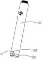
- FIG. 1is a perspective view showing the structure of a battery according to an embodiment of the present invention.
- FIG. 2is a perspective view showing the assembled structure of the battery tail cover of FIG. 1.
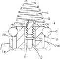
- Figure 3is an exploded view of the first embodiment of the battery tail cap of Figure 2;
- Figure 4is a cross-sectional view of the first embodiment of the battery tail cap of Figure 2;
- Figure 5is an exploded view of the second embodiment of the battery tail cap of Figure 2;
- Figure 6is a cross-sectional view of the second embodiment of the battery tail cap of Figure 2;
- a battery deviceincludes a battery rod 101 and a battery tail cover 100 mounted on the battery rod 101 .
- the battery rod 101is provided with a positioning hole 102 on the circumferential surface of the bottom portion thereof.
- the battery tail cover 100includes a base 1, an elastic abutting member 2, and a positioning ball 3.
- the base 1includes a cover plate 11 and an upper end of the top surface of the cover plate 11 extending upwardly to form a socket sleeve 12 for inserting into the battery rod 101.
- the socket sleeve 12has a receiving cavity 13 , and the socket sleeve 12 is provided with a through hole 120 . .
- the elastic abutting member 2is located in the receiving cavity 13 and fixed to the cover plate 11.
- the positioning ball 3is interposed between the elastic abutting member 2 and the plug sleeve 12, and the elastic restoring force of the positioning ball 3 through the elastic abutting member 2 is obtained.
- the cardis caught in the through hole 120 and protrudes into the positioning hole 102. It can be understood that the positioning ball 3 partially protrudes into the through hole 120 under the elastic restoring force of the elastic abutting member 2 and is caught in the positioning hole 102.
- the positioning ball 3is pressed by the inner wall of the battery rod 101 to move toward the elastic abutting member 2, so that the battery tail cover 100 enters the battery rod 101.
- the elastic restoring force of the elastic abutting member 2pushes the positioning ball 3 to cause the positioning ball to be caught in the positioning hole 102.
- it is only necessary to externally press the positioning ball 3so that the positioning ball 3 is disengaged from the positioning hole 102, and then the battery tail cover 100 is rotated to facilitate disassembly and assembly.
- the cross section of the plug sleeve 12 in the vertical directionhas a convex shape, in other words, the plug sleeve 12 is composed of two parts, and includes a first sleeve body formed extending from the periphery of the cover 11 . And a second sleeve body connected to the first body portion, the diameter of the first sleeve portion is larger than the diameter of the second sleeve portion, and the second sleeve portion is inserted into the battery rod 101 such that the top portion of the second sleeve portion The end face can be attached to the bottom end surface of the battery rod 101 to seal the battery rod 101.
- the elastic abutting member 2is a cylinder made of soft silicone rubber. Further, the circumferential surface of the elastic abutting member 2 is provided with a positioning groove 20 for positioning the positioning ball 3. It can be understood that the positioning ball 3 is disposed in the positioning groove 20 to facilitate the installation of the positioning ball 3.
- the elastic restoring force of the elastic abutting member 2is provided by the elastic ability of the soft silicone member itself.
- the positioning groove 20extends from the bottom of the elastic abutting member 2 to the top of the elastic abutting member 2, and has a C-shaped cross section in the lateral direction, in other words, the positioning groove 20 is semi-cylindrical, so that the installation is convenient. Position the ball 3.
- the battery tail cover 100further includes a pressing block 4 and a fixing screw 5, and the pressing block 4 presses the elastic abutting member 2, and the fixing screw 5 is inserted into the cover plate 11 through the pressing block 4 and the elastic abutting member 2. Inside, the end of the fixing screw 5 abuts against the pressing block 4 to press the elastic abutting member 2 to fix the elastic abutting member 2 to the cover plate 11.
- the pressure block 4is provided with a through hole 401 through which the fixing screw 5 passes.
- the top surface of the cover plate 11further extends a fixing post 110 located in the receiving cavity 13, and the fixing column 110 is provided with The fixing hole 111 of the fixing screw 5 is locked, and the elastic abutting member 2 is provided with a through hole 201 through which the fixing post 110 is inserted.
- the fixing screw 5is locked into the fixing hole 111 through the through hole 401, and the end of the fixing screw 5 is pressed.
- the block 4presses the pressing block 4 against the elastic abutting member 2 to fix the elastic abutting member 2 to the base 1.
- the fixing post 110penetrates the through hole 201 of the elastic abutting member 2, and the pressing block 4 is placed on the top surface of the elastic abutting member 2 and the through hole 401 on the pressing block 4
- the fixing screw 5is locked into the fixing hole 111 through the through hole 401 to fix the elastic abutting member 2 and the cover plate 11 together.
- the pressing block 4in order to prevent the pressing block 4 from being displaced at the top of the elastic abutting member 2 when the pressing block 4 is mounted, the pressing block 4 includes a pressing plate 40 and a ring extending downward from the bottom surface of the pressing plate 40.
- the wall 42has a through hole 401 disposed on the pressing plate 40.
- the elastic abutting member 2is located in a space surrounded by the annular wall 42 such that when the pressing block 4 is displaced, the elastic abutting member 2 will abut against the annular wall 42 to avoid The compact 4 is detached.
- the bottom end of the annular wall 42is provided with a avoidance slit 420 that cooperates with the positioning ball 3.
- the battery tail cover 100further includes a positive electrode spring 6 which is fixed to the top surface of the compact 4 by a fixing screw 5. Specifically, the end of the fixing screw 5 presses the bottom end of the positive electrode spring 6 against the top surface of the compact 4, thereby fixing the positive electrode spring 6 to the top surface of the compact 4.
- the number of the positioning balls 3is two, and correspondingly, the number of the through holes 120 is also two and preferably symmetrically disposed on the second sleeve portion of the plug sleeve 12.
- the number of the positioning grooves 20is two and preferably symmetrically disposed on the circumferential surface of the elastic abutting member 2, and the number of the avoidance slits 420 is two, which are preferably symmetrically disposed at the bottom end of the annular wall 42, positioning The number of holes 102 is also two.
- the second embodiment of the battery device of the present inventionis substantially identical in construction to the first embodiment of the battery device of the present invention, except that the resilient abutment member 2 is different.
- the elastic urging member 2includes a connecting post 22 and a urging spring 24.
- the connecting post 22is provided with a through hole 201.
- the circumferential surface of the connecting post 22is provided with a receiving groove 220 for urging the spring 24.
- One endis received in the accommodating groove 220, and the other end of the urging spring 24 abuts against the positioning ball 3.
- the elastic restoring force of the elastic abutting member 2is generated by the abutting spring 24.
- the number of the positioning balls 3is also two. Accordingly, the number of the urging springs 24 is two, and the number of the accommodating grooves 220 is two and preferably symmetrically disposed on the connecting post 22.
- the battery tail cover 100is inserted into the through hole 120 of the base 1 by the elastic restoring force of the elastic abutting member 2, and when the battery tail cover 100 is mounted on the battery rod 101, the battery tail cover 100
- the positioning ball 3is pressed by the inner wall of the battery rod 101, and is moved toward the direction of the elastic abutting member 2.
- the elastic restoring force of the elastic abutting member 2pushes the positioning ball 3 to position the positioning ball.
- the positioning ball 3is only required to be externally pressed to disengage the positioning ball 3 from the positioning hole 102, and then the battery tail cover 100 is rotated to facilitate disassembly and assembly.
Landscapes
- Connection Of Batteries Or Terminals (AREA)
- Toys (AREA)
Abstract
Description
Translated fromChinese本发明涉及电池技术领域,尤其涉及一种电池装置。The present invention relates to the field of battery technologies, and in particular, to a battery device.
目前市场上的电子烟,如果所用电池为软包电池,软包电池的电池杆与电池尾盖通常采用紧配连接;如果所用电池为可充电的钢壳电池,钢壳电池的电池杆与尾盖的连接大多采用螺纹连接,然而由于螺纹连接方式容易错位,尤其对小烟用户来说,因电池容量较小,电池电量消耗会较快,需经常性取出电池进行充电,此种螺纹连接方式不便于用户拆装,从而导致用户的体验感变差。At present, the electronic cigarette on the market, if the battery used is a soft pack battery, the battery rod and the battery tail cover of the soft pack battery are usually tightly connected; if the battery used is a rechargeable steel shell battery, the battery rod and the tail of the steel shell battery Most of the connections of the cover are threaded. However, because the threaded connection is easy to be misaligned, especially for small smoke users, because the battery capacity is small, the battery power consumption will be faster, and the battery needs to be taken out frequently for charging. It is not convenient for the user to disassemble, which leads to a worse user experience.
发明内容Summary of the invention
有鉴于此,本发明的实施例提供了一种电池装置,以便于方便快捷的安装在电池杆上。In view of this, embodiments of the present invention provide a battery device that is conveniently and quickly mounted on a battery pole.
本发明的实施例提供一种电池装置,包括电池杆及安装于所述电池杆的电池尾盖,所述电池尾盖包括底座,所述底座包括盖板及自所述盖板的顶面周缘向上延伸形成插接套,所述插接套具有收容腔,所述电池杆于其底部的圆周面上设有定位孔,所述电池尾盖还包括弹性抵推件及定位球,所述插接套上设置有通孔,所述弹性抵推件位于所述收容腔内并与所述盖板固定,所述定位球夹设在所述弹性抵推件与所述插接套之间,且所述定位球通过所述弹性抵推件的弹性回复力卡在所述通孔内并部分凸伸出所述通孔,当所述电池尾盖与所述电池杆装配时,所述定位球卡固在所述定位孔内。Embodiments of the present invention provide a battery device including a battery rod and a battery tail cover mounted to the battery rod, the battery tail cover including a base, the base including a cover plate and a top periphery of the cover plate Extending upwardly to form a plug sleeve, the plug sleeve has a receiving cavity, the battery rod is provided with a positioning hole on a circumferential surface of the bottom thereof, and the battery tail cover further comprises an elastic abutting member and a positioning ball, the plug The through sleeve is provided with a through hole, the elastic abutting member is located in the receiving cavity and is fixed to the cover plate, and the positioning ball is sandwiched between the elastic abutting member and the plug sleeve. And the positioning ball is caught in the through hole by the elastic restoring force of the elastic abutting member and partially protrudes from the through hole, and the positioning is performed when the battery tail cover is assembled with the battery rod The ball is stuck in the positioning hole.
进一步地,所述弹性抵推件为软性硅胶制成的柱体。Further, the elastic abutting member is a cylinder made of soft silicone.
进一步地,所述弹性抵推件的圆周面上设有用于定位所述定位球的定位槽。Further, a positioning groove for positioning the positioning ball is disposed on a circumferential surface of the elastic abutting member.
进一步地,所述定位槽自所述弹性抵推件底部延伸至所述弹性抵推件的顶部。Further, the positioning groove extends from the bottom of the elastic abutting member to the top of the elastic abutting member.
进一步地,所述电池尾盖还包括压块及固定螺丝,所述固定螺丝穿过所述压块及所述弹性抵推件锁入盖板内,所述固定螺丝的端头抵推所述压块压紧所述弹性抵推件将所述弹性抵推件固定在所述盖板上。Further, the battery tail cover further includes a pressing block and a fixing screw, the fixing screw is locked into the cover plate through the pressing block and the elastic abutting member, and the end of the fixing screw is pushed against the The pressing block presses the elastic abutting member to fix the elastic abutting member to the cover plate.
进一步地,所述压块上设有供所述固定螺丝穿过的过孔,所述盖板的顶面上还延伸出位于所述收容腔内的固定柱,所述固定柱上设有供所述固定螺丝锁入的固定孔,所述弹性抵推件上设置有供所述固定柱穿入的穿孔。Further, the pressure block is provided with a through hole through which the fixing screw passes, and a top surface of the cover plate further extends a fixing post located in the receiving cavity, and the fixing column is provided with The fixing screw is locked into the fixing hole, and the elastic abutting member is provided with a through hole for the fixing column to penetrate.
进一步地,所述压块包括压板及自所述压板的底面向下延伸形成的环形壁,所述过孔设置在所述压板上,所述弹性抵推件位于所述环形壁与所述底座所围成的空间内。Further, the pressing block includes a pressing plate and an annular wall extending downward from a bottom surface of the pressing plate, the through hole is disposed on the pressing plate, and the elastic abutting member is located at the annular wall and the base Within the enclosed space.
进一步地,所述环形壁的底端设有与所述定位球配合的避位切口。Further, the bottom end of the annular wall is provided with a avoidance slit that cooperates with the positioning ball.
进一步地,所述电池尾盖还包括正极弹簧,所述正极弹簧通过固定螺丝固定在所述压块的顶面上Further, the battery tail cover further includes a positive electrode spring, and the positive electrode spring is fixed on a top surface of the pressure block by a fixing screw
进一步地,所述弹性抵推件包括连接柱及抵推弹簧,所述连接柱的圆周面上设有容置槽,所述抵推弹簧的一端容置于所述容置槽内,所述抵推弹簧的另一端抵靠所述定位球。Further, the elastic abutting member includes a connecting post and a urging spring, and a receiving groove is disposed on a circumferential surface of the connecting post, and one end of the urging spring is received in the accommodating groove, The other end of the urging spring abuts against the positioning ball.
本发明还提供一种电池装置,包括电池杆及安装于所述电池杆的电池尾盖,所述电池尾盖包括具有通孔的底座,所述电池杆于其底部的圆周面上设有定位孔,所述电池尾盖还包括弹性抵推件及定位球,所述定位球通过所述弹性抵推件的弹性回复力卡在所述通孔内并部分凸伸出所述通孔,当所述电池尾盖与所述电池杆装配时,所述定位球卡固在所述定位孔内。The invention also provides a battery device comprising a battery rod and a battery tail cover mounted on the battery rod, the battery tail cover comprising a base having a through hole, the battery rod being positioned on a circumferential surface of the bottom portion thereof a hole, the battery tail cover further includes an elastic abutting member and a positioning ball, and the positioning ball is caught in the through hole by the elastic restoring force of the elastic abutting member and partially protrudes from the through hole, when When the battery tail cover is assembled with the battery rod, the positioning ball is fixed in the positioning hole.
进一步地,所述底座包括盖板及自所述盖板的顶面周缘向上延伸形成插接套,通孔设置在所述插接套上。Further, the base comprises a cover plate and extends upward from a peripheral edge of the top surface of the cover plate to form a plug sleeve, and a through hole is disposed on the plug sleeve.
进一步地,所述插接套具有收容腔,所述弹性抵推件位于所述收容腔内并与所述盖板固定,所述定位球夹设在所述弹性抵推件与所述插接套之间。Further, the insertion sleeve has a receiving cavity, and the elastic abutting member is located in the receiving cavity andThe cover ball is fixed to the cover plate, and the positioning ball is sandwiched between the elastic abutting member and the insertion sleeve.
进一步地,所述弹性抵推件为软性硅胶制成的柱体。Further, the elastic abutting member is a cylinder made of soft silicone.
进一步地,所述弹性抵推件的圆周面上设有用于定位所述定位球的定位槽。Further, a positioning groove for positioning the positioning ball is disposed on a circumferential surface of the elastic abutting member.
进一步地,所述定位槽自所述弹性抵推件底部延伸至所述弹性抵推件的顶部。Further, the positioning groove extends from the bottom of the elastic abutting member to the top of the elastic abutting member.
进一步地,所述电池尾盖还包括压块及固定螺丝,所述固定螺丝穿过所述压块及所述弹性抵推件锁入盖板内,所述固定螺丝的端头抵推所述压块压紧所述弹性抵推件将所述弹性抵推件固定在所述盖板上。Further, the battery tail cover further includes a pressing block and a fixing screw, the fixing screw is locked into the cover plate through the pressing block and the elastic abutting member, and the end of the fixing screw is pushed against the The pressing block presses the elastic abutting member to fix the elastic abutting member to the cover plate.
进一步地,所述压块上设有供所述固定螺丝穿过的过孔,所述盖板的顶面上还延伸出位于所述收容腔内的固定柱,所述固定柱上设有供所述固定螺丝锁入的固定孔,所述弹性抵推件上设置有供所述固定柱穿入的穿孔。Further, the pressure block is provided with a through hole through which the fixing screw passes, and a top surface of the cover plate further extends a fixing post located in the receiving cavity, and the fixing column is provided with The fixing screw is locked into the fixing hole, and the elastic abutting member is provided with a through hole for the fixing column to penetrate.
进一步地,所述压块包括压板及自所述压板的底面向下延伸形成的环形壁,所述过孔设置在所述压板上,所述弹性抵推件位于所述环形壁与所述底座所围成的空间内。Further, the pressing block includes a pressing plate and an annular wall extending downward from a bottom surface of the pressing plate, the through hole is disposed on the pressing plate, and the elastic abutting member is located at the annular wall and the base Within the enclosed space.
进一步地,所述弹性抵推件包括连接柱及抵推弹簧,所述连接柱的圆周面上设有容置槽,所述抵推弹簧的一端容置于所述容置槽内,所述抵推弹簧的另一端抵靠所述定位球。Further, the elastic abutting member includes a connecting post and a urging spring, and a receiving groove is disposed on a circumferential surface of the connecting post, and one end of the urging spring is received in the accommodating groove, The other end of the urging spring abuts against the positioning ball.
进一步地,所述电池尾盖还包括正极弹簧,所述正极弹簧通过固定螺丝固定在所述压块的顶面上。Further, the battery tail cover further includes a positive electrode spring, and the positive electrode spring is fixed on a top surface of the pressure block by a fixing screw.
本发明的实施例提供的技术方案带来的有益效果是:The technical solutions provided by the embodiments of the present invention have the following beneficial effects:
本发明电池装置,其电池尾盖通过弹性抵推件的弹性回复力将定位球卡入底座的通孔,在将电池尾盖装入电池杆时,电池尾盖的定位球受到电池杆的内壁挤压,向靠近弹性抵推件的方向移动,以便于电池尾盖进入电池杆内,当定位球与电池杆上的定位孔对齐时,弹性抵推件的弹性回复力抵推定位球使定位球卡入定位孔内,当需要将电池尾盖拆卸下来时,只需在外部按压定位球使得定位球脱离定位孔,然后旋转电池尾盖方便拆装。In the battery device of the present invention, the battery tail cover clamps the positioning ball into the through hole of the base by the elastic restoring force of the elastic abutting member, and when the battery tail cover is inserted into the battery rod, the positioning ball of the battery tail cover is received by the inner wall of the battery rod Squeeze, move in the direction of the elastic abutting member, so that the battery tail cover enters the battery rod. When the positioning ball is aligned with the positioning hole on the battery rod, the elastic restoring force of the elastic abutting member pushes the positioning ball to make the positioningThe ball is snapped into the positioning hole. When the battery tail cover needs to be removed, the positioning ball is only pressed outside to make the positioning ball out of the positioning hole, and then the battery tail cover is rotated to facilitate disassembly and assembly.
图1是本发明实施例的电池的立体结构示意图。1 is a perspective view showing the structure of a battery according to an embodiment of the present invention.
图2是图1中的电池尾盖的立体结构组装图。2 is a perspective view showing the assembled structure of the battery tail cover of FIG. 1.
图3是图2中的电池尾盖第一实施例的分解图。Figure 3 is an exploded view of the first embodiment of the battery tail cap of Figure 2;
图4是图2中的电池尾盖第一实施例的剖视图。Figure 4 is a cross-sectional view of the first embodiment of the battery tail cap of Figure 2;
图5是图2中的电池尾盖第二实施例的分解图。Figure 5 is an exploded view of the second embodiment of the battery tail cap of Figure 2;
图6是图2中的电池尾盖第二实施例的剖视图。Figure 6 is a cross-sectional view of the second embodiment of the battery tail cap of Figure 2;
主要元件符号说明Main component symbol description
电池尾盖 100
电池杆 101
定位孔 102
底座 1
弹性抵推件 2
定位球 3
盖板 11
插接套 12
通孔 120Through
收容腔 13
压块 4
固定螺丝 5Fixing
过孔 401Via 401
固定柱 110Fixed
固定孔 111Fixing
穿孔 201
压板 40
环形壁 42
避位切口 420Avoidance cut 420
正极弹簧 6
连接柱 22Connecting
抵推弹簧 24
容置槽 220Locating
为使本发明的目的、技术方案和优点更加清楚,下面将结合附图对本发明实施方式作进一步地描述。In order to make the objects, technical solutions and advantages of the present invention more apparent, the embodiments of the present invention will be further described with reference to the accompanying drawings.
实施例1Example 1
请参考图1至图4,本发明第一实施例提供的电池装置,包括电池杆101及安装于电池杆101的电池尾盖100。其中,电池杆101于其底部的圆周面上设有定位孔102。电池尾盖100包括底座1、弹性抵推件2及定位球3。底座1包括盖板11及自盖板11的顶面周缘向上延伸形成用于插入电池杆101内的插接套12,插接套12具有收容腔13,插接套12上设置有通孔120。弹性抵推件2位于收容腔13内并与盖板11固定,定位球3夹设在弹性抵推件2与插接套12之间,且定位球3通过弹性抵推件2的弹性回复力卡在通孔120内并凸伸至卡在定位孔102内。可以理解的是,定位球3在弹性抵推件2的弹性回复力的作用下部分凸伸出通孔120后卡在定位孔102内。Referring to FIG. 1 to FIG. 4 , a battery device according to a first embodiment of the present invention includes a
具体地,在将电池尾盖100安装于电池杆101时,定位球3受到电池杆101的内壁挤压,向靠近弹性抵推件2的方向移动,以便于电池尾盖100进入电池杆101内,当定位球3与电池杆101上的定位孔102对齐时,弹性抵推件2的弹性回复力抵推定位球3使定位球卡入定位孔102内。当需要将电池尾盖100拆卸下来时,只需在外部按压定位球3使得定位球3脱离定位孔102,然后旋转电池尾盖100方便拆装。Specifically, when the
需要说明的是,插接套12的沿着竖直方向上的截面呈凸字形,换句话说就是插接套12由两部分构成,包括与自盖11的周缘延伸形成的第一套体部及于第一套体部连接的第二套体部,第一套体部的直径大于第二套体部的直径,第二套体部插入电池杆101内,这样第二套体部的顶部端面即可与电池杆101的底部端面贴合在一起,以将电池杆101密封。It should be noted that the cross section of the
在本实施例中,弹性抵推件2为软性硅胶制成的柱体,进一步地,弹性抵推件2的圆周面上设有用于定位定位球3的定位槽20。可以理解的是,定位球3设置在定位槽20内便于安装定位球3,弹性抵推件2的弹性回复力由软性硅胶件自身具备的弹性能力提供。优选地,定位槽20自弹性抵推件2的底部延伸至弹性抵推件2的顶部,且其横向上的截面呈C形,换句话说,也就是定位槽20呈半圆柱状,如此方便安装定位球3。In the present embodiment, the elastic abutting
在本实施例中,电池尾盖100还包括压块4及固定螺丝5,压块4压紧弹性抵推件2,固定螺丝5穿过压块4及弹性抵推件2锁入盖板11内,固定螺丝5的端头抵推压块4压紧弹性抵推件2将弹性抵推件2固定在盖板11上。In this embodiment, the
在本实施例中,压块4上设有供固定螺丝5穿过的过孔401,盖板11的顶面上还延伸出位于收容腔13内的固定柱110,固定柱110上设有供固定螺丝5锁入的固定孔111,弹性抵推件2上设置有供固定柱110穿入的穿孔201,固定螺丝5穿过过孔401锁入固定孔111,固定螺丝5的端头压迫压块4,使压块4压紧弹性抵推件2从而将弹性抵推件2与底座1固定连接在一起。具体地,在将电池尾盖100组装在一起时,固定柱110穿入弹性抵推件2的穿孔201,压块4置于弹性抵推件2的顶面且压块4上的过孔401与固定孔111对齐,固定螺丝5穿过过孔401锁入固定孔111内将弹性抵推件2与盖板11固定在一起。In the embodiment, the
在本实施例中,为了避免在安装压块4时,压块4在弹性抵推件2的顶部发生偏移而脱落,压块4包括压板40及自压板40的底面向下延伸形成的环形壁42,过孔401设置在压板40上,弹性抵推件2位于环形壁42所围成的空间内,这样压块4在偏移时,弹性抵推件2将抵靠环形壁42,避免压块4脱落。进一步地,为了避免环形壁42与定位球3发生干涉,环形壁42的底端设有与定位球3配合的避位切口420。In this embodiment, in order to prevent the
在本实施例中,电池尾盖100还包括正极弹簧6,正极弹簧6通过固定螺丝5固定在压块4的顶面上。具体地,固定螺丝5的端头将正极弹簧6的底端压在压块4的顶面,从而将正极弹簧6固定在压块4的顶面上。In the present embodiment, the
需要说明的是,在本实施例中,定位球3的数量为两个,相应地,通孔120的数量也为两个且优选地对称地设置在插接套12的第二套体部上,定位槽20的数量为两个且优选地对称地设置在弹性抵推件2的圆周面上,避位切口420的数量为两个其优选地对称地设置在环形壁42的底端,定位孔102的数量同样为两个。It should be noted that, in this embodiment, the number of the
实施例2Example 2
请参阅图1-2及图5和6,本发明电池装置的第二实施与本发明电池装置的第一实施的结构基本相同,其不同之处仅在于弹性抵推件2不同。在第二实施例中,弹性抵推件2包括连接柱22及抵推弹簧24,连接柱22上设有穿孔201,连接柱22的圆周面上设有容置槽220,抵推弹簧24的一端容置于容置槽220内,抵推弹簧24的另一端抵靠定位球3。可以理解的是,在该实施例中,弹性抵推件2的弹性回复力由抵推弹簧24产生。在本实施例中,定位球3的数量同样为两个,相应地,抵推弹簧24的数量为两个,容置槽220的数量为两个且优选地对称地设置在连接柱22上。Referring to Figures 1-2 and Figures 5 and 6, the second embodiment of the battery device of the present invention is substantially identical in construction to the first embodiment of the battery device of the present invention, except that the
本发明的有益效果是:The beneficial effects of the invention are:
本发明电池装置,其电池尾盖100通过弹性抵推件2的弹性回复力将定位球3卡入底座1的通孔120,在将电池尾盖100安装于电池杆101时,电池尾盖100的定位球3受到电池杆101的内壁挤压,向靠近弹性抵推件2的方向移动,以便于电池尾盖100进入电池杆101内,当定位球3与电池杆101上的定位孔102对齐时,弹性抵推件2的弹性回复力抵推定位球3使定位球卡入定位孔102内,当需要将电池尾盖100拆卸下来时,只需在外部按压定位球3使得定位球3脱离定位孔102,然后旋转电池尾盖100方便拆装。In the battery device of the present invention, the
在本文中,所涉及的前、后、上、下等方位词是以附图中零部件位于图中以及零部件相互之间的位置来定义的,只是为了表达技术方案的清楚及方便。应当理解,所述方位词的使用不应限制本申请请求保护的范围。In this document, the preceding, following, upper and lower orientations are defined by the position of the components in the drawings and the positions of the components, just to express the clarity and convenience of the technical solution. It should be understood that the use of the orientation words should not limit the scope of the claimed invention.
在不冲突的情况下,本文中上述实施例及实施例中的特征可以相互结合。以上所述仅为本发明的较佳实施例,并不用以限制本发明,凡在本发明的精神和原则之内,所作的任何修改、等同替换、改进等,均应包含在本发明的保护范围之内。The features of the above-described embodiments and embodiments herein may be combined with each other without conflict. The above are only the preferred embodiments of the present invention, and are not intended to limit the present invention. Any modifications, equivalents, improvements, etc., which are within the spirit and scope of the present invention, should be included in the protection of the present invention. Within the scope.
Claims (21)
Translated fromChineseApplications Claiming Priority (2)
| Application Number | Priority Date | Filing Date | Title |
|---|---|---|---|
| CN201621237420.2UCN206271784U (en) | 2016-11-18 | 2016-11-18 | Cell apparatus |
| CN201621237420.2 | 2016-11-18 |
Publications (1)
| Publication Number | Publication Date |
|---|---|
| WO2018090684A1true WO2018090684A1 (en) | 2018-05-24 |
Family
ID=59040257
Family Applications (1)
| Application Number | Title | Priority Date | Filing Date |
|---|---|---|---|
| PCT/CN2017/097087CeasedWO2018090684A1 (en) | 2016-11-18 | 2017-08-11 | Battery device |
Country Status (2)
| Country | Link |
|---|---|
| CN (1) | CN206271784U (en) |
| WO (1) | WO2018090684A1 (en) |
Cited By (2)
| Publication number | Priority date | Publication date | Assignee | Title |
|---|---|---|---|---|
| CN109774883A (en)* | 2019-03-06 | 2019-05-21 | 浙江同博科技发展有限公司 | The tamper of boat-carrying communication terminal pedestal, anti-loose structure |
| EP3964091A4 (en)* | 2019-04-30 | 2023-03-29 | Changzhou Patent Electronic Technology Co., Ltd | ATOMIZERS AND ELECTRONIC CIGARETTE WITH IT |
Families Citing this family (5)
| Publication number | Priority date | Publication date | Assignee | Title |
|---|---|---|---|---|
| CN206271784U (en)* | 2016-11-18 | 2017-06-20 | 卓尔悦欧洲控股有限公司 | Cell apparatus |
| CN108007628A (en)* | 2017-12-27 | 2018-05-08 | 杭州集普科技有限公司 | A kind of belt force sensor |
| CN108493367B (en)* | 2018-03-21 | 2020-11-10 | 厦门光远照明有限公司 | Quick-release structure for quickly replacing lamp battery |
| CN111406993A (en)* | 2019-09-30 | 2020-07-14 | 深圳市艾维普思科技有限公司 | e-cigarette |
| CN111224023B (en)* | 2020-01-18 | 2023-02-10 | 深圳市吉迩科技有限公司 | Battery assembly, aerosol generating device and battery replacing method |
Citations (5)
| Publication number | Priority date | Publication date | Assignee | Title |
|---|---|---|---|---|
| CN202566290U (en)* | 2012-05-10 | 2012-12-05 | 卓尔悦(常州)电子科技有限公司 | Power supply device and electronic cigarette |
| US20130152954A1 (en)* | 2011-12-16 | 2013-06-20 | Janty Asia Co. Ltd | Battery replacement type e-cigarette |
| CN203446531U (en)* | 2013-07-24 | 2014-02-26 | 刘秋明 | Electronic cigarette |
| CN204540830U (en)* | 2015-03-31 | 2015-08-12 | 深圳市联君烟博士电子技术有限责任公司 | A kind of electronic cigarette |
| CN206271784U (en)* | 2016-11-18 | 2017-06-20 | 卓尔悦欧洲控股有限公司 | Cell apparatus |
- 2016
- 2016-11-18CNCN201621237420.2Upatent/CN206271784U/enactiveActive
- 2017
- 2017-08-11WOPCT/CN2017/097087patent/WO2018090684A1/ennot_activeCeased
Patent Citations (5)
| Publication number | Priority date | Publication date | Assignee | Title |
|---|---|---|---|---|
| US20130152954A1 (en)* | 2011-12-16 | 2013-06-20 | Janty Asia Co. Ltd | Battery replacement type e-cigarette |
| CN202566290U (en)* | 2012-05-10 | 2012-12-05 | 卓尔悦(常州)电子科技有限公司 | Power supply device and electronic cigarette |
| CN203446531U (en)* | 2013-07-24 | 2014-02-26 | 刘秋明 | Electronic cigarette |
| CN204540830U (en)* | 2015-03-31 | 2015-08-12 | 深圳市联君烟博士电子技术有限责任公司 | A kind of electronic cigarette |
| CN206271784U (en)* | 2016-11-18 | 2017-06-20 | 卓尔悦欧洲控股有限公司 | Cell apparatus |
Cited By (3)
| Publication number | Priority date | Publication date | Assignee | Title |
|---|---|---|---|---|
| CN109774883A (en)* | 2019-03-06 | 2019-05-21 | 浙江同博科技发展有限公司 | The tamper of boat-carrying communication terminal pedestal, anti-loose structure |
| CN109774883B (en)* | 2019-03-06 | 2023-09-08 | 浙江同博科技发展有限公司 | Anti-disassembly and anti-loosening structure for ship-borne communication terminal base |
| EP3964091A4 (en)* | 2019-04-30 | 2023-03-29 | Changzhou Patent Electronic Technology Co., Ltd | ATOMIZERS AND ELECTRONIC CIGARETTE WITH IT |
Also Published As
| Publication number | Publication date |
|---|---|
| CN206271784U (en) | 2017-06-20 |
Similar Documents
| Publication | Publication Date | Title |
|---|---|---|
| WO2018090684A1 (en) | Battery device | |
| US20140085781A1 (en) | Button assembly and electronic device using the same | |
| US6637082B1 (en) | Quick holder | |
| US8471133B1 (en) | Quick-release cymbal felt locating device | |
| US8844122B2 (en) | Assembly fixture | |
| US8760876B2 (en) | USB memory stick | |
| JP3127080U (en) | Tool chuck device | |
| TW201531199A (en) | Mobile terminal housing | |
| US8573990B2 (en) | Cover structure | |
| TW201304326A (en) | Power supply structure | |
| US8434206B2 (en) | Clutching jig | |
| US8286317B2 (en) | Clutching jig | |
| US20050238422A1 (en) | Snap connecting device | |
| CN215488657U (en) | Clamping assembly and clamping device for clamping mobile equipment | |
| US8202133B1 (en) | Probe connector | |
| CN214254911U (en) | electrical connector device | |
| US8464412B2 (en) | Clutching jig | |
| US20110051263A1 (en) | Clutching jig | |
| KR200413192Y1 (en) | Tent Pole End Connection | |
| US9465410B2 (en) | Electronic device housing and method for manufacturing the same | |
| US20050245139A1 (en) | Bulb assembly | |
| US7335051B2 (en) | Battery holder | |
| CN220093798U (en) | Spacing subassembly and clamping device | |
| CN107591633A (en) | Electric connector | |
| CN216202073U (en) | Quick-release connecting piece |
Legal Events
| Date | Code | Title | Description |
|---|---|---|---|
| 121 | Ep: the epo has been informed by wipo that ep was designated in this application | Ref document number:17871782 Country of ref document:EP Kind code of ref document:A1 | |
| NENP | Non-entry into the national phase | Ref country code:DE | |
| 122 | Ep: pct application non-entry in european phase | Ref document number:17871782 Country of ref document:EP Kind code of ref document:A1 |