WO2018090675A2 - Plug connector and socket connector - Google Patents
Plug connector and socket connectorDownload PDFInfo
- Publication number
- WO2018090675A2 WO2018090675A2PCT/CN2017/096234CN2017096234WWO2018090675A2WO 2018090675 A2WO2018090675 A2WO 2018090675A2CN 2017096234 WCN2017096234 WCN 2017096234WWO 2018090675 A2WO2018090675 A2WO 2018090675A2
- Authority
- WO
- WIPO (PCT)
- Prior art keywords
- plug
- socket
- bosses
- tongue
- boss
- Prior art date
- Legal status (The legal status is an assumption and is not a legal conclusion. Google has not performed a legal analysis and makes no representation as to the accuracy of the status listed.)
- Ceased
Links
Images


Classifications
- H—ELECTRICITY
- H01—ELECTRIC ELEMENTS
- H01R—ELECTRICALLY-CONDUCTIVE CONNECTIONS; STRUCTURAL ASSOCIATIONS OF A PLURALITY OF MUTUALLY-INSULATED ELECTRICAL CONNECTING ELEMENTS; COUPLING DEVICES; CURRENT COLLECTORS
- H01R13/00—Details of coupling devices of the kinds covered by groups H01R12/70 or H01R24/00 - H01R33/00
- H01R13/40—Securing contact members in or to a base or case; Insulating of contact members
- H01R13/42—Securing in a demountable manner
- H01R13/436—Securing a plurality of contact members by one locking piece or operation
- H—ELECTRICITY
- H01—ELECTRIC ELEMENTS
- H01R—ELECTRICALLY-CONDUCTIVE CONNECTIONS; STRUCTURAL ASSOCIATIONS OF A PLURALITY OF MUTUALLY-INSULATED ELECTRICAL CONNECTING ELEMENTS; COUPLING DEVICES; CURRENT COLLECTORS
- H01R13/00—Details of coupling devices of the kinds covered by groups H01R12/70 or H01R24/00 - H01R33/00
- H01R13/40—Securing contact members in or to a base or case; Insulating of contact members
- H01R13/42—Securing in a demountable manner
- H—ELECTRICITY
- H01—ELECTRIC ELEMENTS
- H01R—ELECTRICALLY-CONDUCTIVE CONNECTIONS; STRUCTURAL ASSOCIATIONS OF A PLURALITY OF MUTUALLY-INSULATED ELECTRICAL CONNECTING ELEMENTS; COUPLING DEVICES; CURRENT COLLECTORS
- H01R13/00—Details of coupling devices of the kinds covered by groups H01R12/70 or H01R24/00 - H01R33/00
- H01R13/44—Means for preventing access to live contacts
- H01R13/447—Shutter or cover plate
- H—ELECTRICITY
- H01—ELECTRIC ELEMENTS
- H01R—ELECTRICALLY-CONDUCTIVE CONNECTIONS; STRUCTURAL ASSOCIATIONS OF A PLURALITY OF MUTUALLY-INSULATED ELECTRICAL CONNECTING ELEMENTS; COUPLING DEVICES; CURRENT COLLECTORS
- H01R13/00—Details of coupling devices of the kinds covered by groups H01R12/70 or H01R24/00 - H01R33/00
- H01R13/46—Bases; Cases
- H01R13/502—Bases; Cases composed of different pieces
- H01R13/506—Bases; Cases composed of different pieces assembled by snap action of the parts
- H—ELECTRICITY
- H01—ELECTRIC ELEMENTS
- H01R—ELECTRICALLY-CONDUCTIVE CONNECTIONS; STRUCTURAL ASSOCIATIONS OF A PLURALITY OF MUTUALLY-INSULATED ELECTRICAL CONNECTING ELEMENTS; COUPLING DEVICES; CURRENT COLLECTORS
- H01R13/00—Details of coupling devices of the kinds covered by groups H01R12/70 or H01R24/00 - H01R33/00
- H01R13/648—Protective earth or shield arrangements on coupling devices, e.g. anti-static shielding
- H01R13/658—High frequency shielding arrangements, e.g. against EMI [Electro-Magnetic Interference] or EMP [Electro-Magnetic Pulse]
- H01R13/6581—Shield structure
- H01R13/6582—Shield structure with resilient means for engaging mating connector
- H—ELECTRICITY
- H01—ELECTRIC ELEMENTS
- H01R—ELECTRICALLY-CONDUCTIVE CONNECTIONS; STRUCTURAL ASSOCIATIONS OF A PLURALITY OF MUTUALLY-INSULATED ELECTRICAL CONNECTING ELEMENTS; COUPLING DEVICES; CURRENT COLLECTORS
- H01R12/00—Structural associations of a plurality of mutually-insulated electrical connecting elements, specially adapted for printed circuits, e.g. printed circuit boards [PCB], flat or ribbon cables, or like generally planar structures, e.g. terminal strips, terminal blocks; Coupling devices specially adapted for printed circuits, flat or ribbon cables, or like generally planar structures; Terminals specially adapted for contact with, or insertion into, printed circuits, flat or ribbon cables, or like generally planar structures
- H01R12/70—Coupling devices
- H01R12/71—Coupling devices for rigid printing circuits or like structures
- H01R12/712—Coupling devices for rigid printing circuits or like structures co-operating with the surface of the printed circuit or with a coupling device exclusively provided on the surface of the printed circuit
- H01R12/716—Coupling device provided on the PCB
- H—ELECTRICITY
- H01—ELECTRIC ELEMENTS
- H01R—ELECTRICALLY-CONDUCTIVE CONNECTIONS; STRUCTURAL ASSOCIATIONS OF A PLURALITY OF MUTUALLY-INSULATED ELECTRICAL CONNECTING ELEMENTS; COUPLING DEVICES; CURRENT COLLECTORS
- H01R24/00—Two-part coupling devices, or either of their cooperating parts, characterised by their overall structure
- H01R24/60—Contacts spaced along planar side wall transverse to longitudinal axis of engagement
Definitions
- the present applicationrelates to the field of connector technologies, and in particular, to a plug connector and a socket connector.
- An electrical connector assemblyalso referred to as a circuit connector, is a conductor device for bridging two conductors on one circuit such that current or signals can flow from one conductor to another. It is widely used in various electrical circuits to function as a connection or disconnection of current or signal.
- the prior art electrical connector assemblyis divided into a plug connector and a socket connector, the socket connector is generally mounted on a printed circuit board, the plug connector is assembled at the wire end, and the plug connector and the plug connector are engaged when the printed circuit board is The line ends.
- the socket connector and the plug connectorare prone to mis-insertion such as oblique insertion or reverse insertion, and the socket connector and the plug connector are obliquely inserted to cause the socket connector or the connector of the plug connector and the other party.
- the metal casingis turned on, a short circuit occurs, which affects the transmission of the electrical connector assembly. If the socket connector and the plug connector are reversely inserted, the signal may be blocked. When the plug is inserted, the connector may be damaged due to excessive force.
- the technical problem to be solved by the embodiments of the present applicationis to provide a plug connector and a socket connector, which can effectively prevent mis-insertion and reduce damage to the connector.
- a technical solution adopted by the present applicationis to provide a plug connector, including:
- the insulating bodycomprises a base and a tongue extending from the base, the two side walls of the tongue respectively extending at least four bosses up and down respectively;
- the plug metal casingfixes the insulating body, and the plug metal casing comprises a plug reinforcement fixed to at least one boss, and the plug reinforcement extends to the inner side of the boss.
- the plug metal casingcomprises an upper wall, a lower wall and two side walls, and at least one side wall of the two side walls is provided with an extension fixed to an outer side surface of the boss, and the plug reinforcement portion is bent from the extension portion toward the inner side surface of the boss The fold is extended and attached to the inner side of the boss.
- the plug metal housingcomprises two plug reinforcements, the same side wall of the tongue plate extending in opposite directions with two bosses, the two plug reinforcements being opposite from the extension of the same side wall of the plug metal housing The direction is bent and extended and attached to the inner side of the two bosses.
- the insulative housingincludes a first insulative housing and a second insulative housing, the first insulative housing includes a first base and a first tongue extending from the first base, the second insulative housing includes a second base and extending from the second base a second tongue plate, the first plug conductive terminal group is disposed on the first tongue plate, and the second plug conductive terminal group is disposed on the second tongue plate;
- the two side walls of the second tongue platerespectively extend up and down with four bosses, and the plug reinforcing portion is fixed to one of the four bosses or two bosses on the same side wall.
- the plug reinforcing portionextends from one side of the extending portion to the boss and then extends toward the inner side surface of the boss.
- the front end of the extending portiondoes not exceed the front end of the boss, and the other side and the side wall of the extending portion are formed with
- the fixing hole, the side wall of the second tongueis provided with a fixing portion that cooperates with the fixing hole.
- the two plug reinforcing portionsextend from both sides of the extending portion to the two bosses and then extend toward the inner side surfaces of the two bosses, and the front end of the extending portion does not exceed the front ends of the two bosses, the extension A fixing hole having a front end opening is disposed on the portion, and a front end of the side wall of the second tongue plate is provided with a fixing portion that cooperates with the fixing hole.
- the first tongueis received between the two protrusions extending in the same direction of the second tongue, and the front end of the first base abuts against the two bosses.
- the first tongueis provided with a stopper, the stopper abuts against the two bosses abutting the front end of one of the first bases, and the plug reinforcement is fixed to the boss disposed opposite to the stopper.
- the embodiment of the present applicationfurther provides a socket connector, including:
- the socket insulative housinghas a receiving space, including an upper wall of the socket, a lower wall of the socket, and two side walls of the socket.
- the inner surface of the upper wall of the socketextends to form a first holding portion, and the inner surface of the lower wall of the socket extends toward the receiving space.
- a second holding portion, the insulating bodyis also provided with a socket proofing unit;
- the first socket conductive terminal groupis disposed on the first holding portion
- the second socket conductive terminal groupis disposed on the second holding portion, and the first holding portion and the second holding portion form at least four boss receiving grooves between the two socket side walls;
- the socket metal casingfixes the insulative body, and the socket metal casing includes a socket reinforcement fixed to the outer side of the foolproof portion.
- the socket metal casingcomprises a metal upper wall, a metal lower wall and two metal side walls, and the two metal sidewalls are bent and extended to the receiving space to have a bent portion, and the two socket side walls of the socket insulating body are provided with a receiving bending portion. a notch portion, the end of the bent portion abuts against the side wall of the socket;
- the socket foolproof portionextends from the lower wall of the socket in a ramp shape to the side wall of the socket, and the notch portion is located above the socket foolproof portion.
- the utility modelhas the beneficial effects that the plug connector of the embodiment of the present application is provided with at least four bosses and a plug reinforcing portion including at least one boss, and the socket connector is provided with a socket.
- the foolproof portionincludes at least four boss receiving grooves and a socket reinforcing portion fixed to the outer side of the foolproof portion, which can effectively prevent mis-insertion and reduce the connection during the process of plugging the plug connector and the socket connector Damage to the device.
- FIG. 1is a perspective structural view of a plug connector of a first embodiment of the present application
- Figure 2is an exploded perspective view of the plug connector of the first embodiment of the present application
- FIG. 3is a structural view of a plug metal casing of a plug connector of a first embodiment of the present application
- FIG. 4is a structural view of a first insulative housing of the plug connector of the first embodiment of the present application.
- FIG. 5is a structural view of a second insulating body of the plug connector of the first embodiment of the present application.
- Figure 6is a perspective structural view of a plug connector of a second embodiment of the present application.
- Figure 7is a structural view showing a plug metal casing of a plug connector of a second embodiment of the present application.
- Figure 8is a structural view of an insulative housing of a plug connector of a second embodiment of the present application.
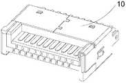
- FIG. 9is a perspective structural view of a socket connector of an embodiment of the present application.
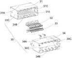
- FIG. 10is an exploded perspective view of the socket connector of the embodiment of the present application.
- FIG. 11is a structural view of a socket insulating body of a socket connector according to an embodiment of the present application.
- Fig. 12is a structural view showing a socket metal casing of the socket connector of the embodiment of the present application.
- FIG. 1is a perspective structural view of a plug connector according to a first embodiment of the present application
- FIG. 2is an exploded perspective view of the plug connector
- FIG. 3is a plug of the plug connector.
- the plug connector 10 of the embodiment of the present inventionincludes an insulative housing 11 including a base portion 11A and a tongue plate 11B extending from the base portion. The two side walls of the tongue plate respectively extend at least four bosses up and down, as shown in FIG.
- the bosses 111B, 112B, 113B, 114B and 115Bare shown; the first plug conductive terminal group 12 is disposed on the side of the tongue 11B; the second plug conductive terminal group 13 is disposed on the opposite side of the tongue 11B;
- the outer casing 14is fixed to the insulative housing 11, and the plug metal outer casing 14 includes a plug reinforcement portion 1432 to which at least one boss is fixed, and the plug reinforcement portion 1432 extends to the inner side surface of the boss.
- the plug metal casing 14includes an upper wall 141, a lower wall 142, and two side walls 143 and 144. At least one side wall of the two side walls is provided with an extension fixed to the outer side surface of the boss, and the plug reinforcement portion The 1432 is bent from the extension portion toward the inner side surface of the boss and is attached to the inner side surface of the boss. As shown in FIG. 3, the side wall 143 is provided with an extending portion 1431 fixed to the outer side surface of the boss 111B. The plug reinforcing portion 1432 is bent and extended from the extending portion 1431 toward the inner side surface of the boss 111B, and is attached to the inner side of the boss 111B. .
- the plug reinforcing portion 1432extends to the inner surface of the boss 111B to the surface of the tongue plate 11B.
- the plug reinforcing portion and the convex portionmay also be used.
- Common fixing structuressuch as card holes and card parts are provided between the inner sides of the table.
- the insulative housingis typically plastic. To reduce damage to the plastic during reverse insertion or insertion, the extension 1431 extends to the end of the boss 111B.
- the insulative housing 11may be an integrally formed structure.
- the insulative housingmay also include a first insulative housing and a second insulative housing.
- the first insulative housing 111includes a first base portion 1111 and a first tongue plate 1112 extending from the first base portion.
- the second insulative housing 112includes a second base portion 1121 and a second base portion.
- the extended second tongue plate 1122has a first plug conductive terminal set 12 disposed on the first tongue plate 1112, a second plug conductive terminal set 13 disposed on the second tongue plate 1122, and two sidewalls of the second tongue plate 1122 respectively Four bosses 1122A, 1122B, 1122C, and 1122D extend upward and downward, and the plug reinforcing portion 1432 is fixed to one of the four bosses.
- the plug reinforcement portion 1432is fixed to the 1122A of the four bosses.
- the plug reinforcement portion 1432extends from one side of the extension portion 1431 to the boss 1122A and then extends toward the inner side surface of the boss 1122A.
- the extension portion 1431The front end of the extending portion 141 is not formed beyond the front end of the boss 1122A, and the other side of the extending portion 1431 is formed with a fixing hole 1430.
- the side wall of the second tongue 1122is provided with a fixing portion 1122E that cooperates with the fixing hole 1430, so that the plug metal shell 14 and the insulation body is better fixed.
- the first tongue 1112is received between the two protrusions extending in the same direction of the second tongue 1122, as shown in FIG. 1122A and 1122C, the front end of the first base portion 1111 abuts against the two bosses.
- the first tongue plate 1112is provided with a stopper block 1112A.
- the stopper block 1112Ais a boss extending from the side wall of the first tongue plate 1112, and the stopper block 1112A is in close contact with the front end of one of the first base portions 1111. After the two bosses are connected, the adjacent bosses further form a stop space. Wherein the height of the stop block 1112A is lower than the height of the boss adjacent thereto, or Its adjacent bosses are flush.
- the plug reinforcement portion 1432is fixed to a boss disposed opposite to the stopper block 1112A, that is, the plug reinforcement portion 1432 is fixed to a boss that is disposed laterally opposite to the stopper block 1112A or disposed vertically opposite to each other.
- the first insulative housing 111is provided with at least one locking hole 1111A
- the second insulative housing 112is provided with a locking post 1121A that cooperates with the locking hole 1111A, and the locking post 1121A is buckled into the locking hole 1111A.
- the first insulative housing 111 and the second insulative housing 112are integrally fixed to facilitate assembly.
- the first insulative housing 111 and the second insulative housing 112may also be thermally bonded or otherwise fixed.
- the central positions of the first base portion 1111 and the second base portion 1112are respectively provided with three first avoiding holes and a second avoiding hole, which are vertically penetrated through the first base portion 1111 and the second base portion 1112, and the first avoiding holes and The position of the second avoidance hole corresponds.
- the first plug conductive terminal group 13 and the second plug conductive terminal group 14each include a plurality of high speed signal terminals, and the high speed signal terminals are exposed in the first avoidance holes and the second avoidance holes, thereby improving the transmission speed of the high speed signal terminals. .
- FIG. 6is a perspective structural view of a plug connector according to a second embodiment of the present application.
- the plug connector 20is different from the foregoing first embodiment in that the plug metal housing 24 includes two plug reinforcement portions 2432A. And 2432B, as shown in Fig. 7, the plug reinforcing portions 2432A and 2432B are fixed to two of the four bosses.
- the same side wall of the tongue plateextends in opposite directions with two bosses, and the two plug reinforcing portions 2432A and 2432B are bent and extended in opposite directions from the extending portion 2431 of the same side wall of the plug metal casing 24.
- the two plug reinforcing portionsmay not be bent and extended from the extending portions of the same side wall, for example, the inner side surfaces of the two bosses disposed obliquely opposite to the different side walls of the tongue plate, the present embodiment This example does not limit this.
- the two plug reinforcing portions 2432A and 2432Bextend from both sides of the extending portion 2431 to cover the two bosses and then extend toward the inner side surfaces of the two bosses.
- the front end of the extending portion 2431does not exceed the front ends of the two bosses, and the extending portion
- the fixing hole 2430 of the front end openingis provided on the 2431.
- the front end of the side wall of the second tongueis provided with a fixing portion 2122E that cooperates with the fixing hole 2430, as shown in FIG.
- the plug reinforcement portionis fixed to the two bosses of the four bosses which are disposed diagonally opposite to the different side walls of the tongue plate, the arrangement of the fixing hole and the fixing portion can be referred to The setting of an embodiment.
- FIG. 9is a perspective structural view of the socket connector of the embodiment of the present application
- FIG. 10is an exploded perspective view of the socket connector
- FIG. 11is a perspective view of the socket connector
- FIG. 12is a structural view of the socket metal housing of the receptacle connector.
- the socket connector 30includes a socket insulation body 31 and a receiving space 310, including a socket upper wall 31A, a socket lower wall 31B, and two socket side walls 31C.
- the inner surface of the socket upper wall 31Aextends toward the receiving space to form a first holding portion.
- the socket insulating body 31is further provided with a socket foolproof portion 313;
- the first socket conductive terminal group 32is disposed on the first holding portion 311;
- the socket conductive terminal group 33is disposed on the second holding portion 312, and the first holding portion 311 and the second holding portion 312 and the two socket side walls 31C form at least four boss receiving grooves 31D;
- the socket metal housing 34includes a socket reinforcement portion 341 that is fixed to the outer side surface of the foolproof portion 313.
- the socket metal casing 34includes a metal upper wall 34A, a metal lower wall 34B, and two metal side walls 34C.
- the two metal side walls 34Care bent and extended toward the receiving space 310, and the bent portions 342 and 343 are extended, and the socket sides of the socket insulating body 31 are provided.
- the wall 31Cis provided with two notches 314 (the other not shown) for accommodating the bent portions, and the ends of the bent portions 342 and 343 abut against the socket side wall 31C.
- the socket metal casing 34 and the socket insulation body 31are prevented from loosening after multiple insertions and removals.
- the bent portions 342 and 343are disposed parallel to the metal sidewall 34C to facilitate fixing the socket insulating body 31 in the socket metal casing 34.
- the bent portionmay not be parallel to the metal.
- the side wall arrangement, or the bent portion and the notched portion,may be provided only in one place.
- the socket foolproof portion 313extends from the socket lower wall 31B in a ramp shape to the socket side wall 31C, and the notch portion 314 is located above the socket foolproof portion 313, because the socket foolproof portion 313 and the stopper block 1112A of the plug connector 10 correspond to each other.
- the settingcan effectively prevent the reverse insertion.
- the front end of the socket metal casing 34extends to the receiving space 310 with a grounding elastic piece 344. among them, The grounding elastic piece 344 is bent and fitted to the socket lower wall 31B of the socket insulating body 31.
- the socket insulating body 31is provided with a spring receiving groove 315 for receiving the grounding elastic piece 344.
- the grounding elastic piece 344 and the receiving groove 315are both plural, and one elastic piece receiving groove 344 corresponds to a grounding elastic piece 315.
- the embodiment of the present applicationfurther provides an electrical connector assembly, comprising the plug connector according to any one of the above, and the socket connector according to any one of the preceding claims; the plug connector when the plug connector is mated with the socket connector
- the bossesare received in the boss slots of the socket connector, wherein the stoppers and their adjacent bosses share a boss receiving groove.
- the plug connectorincludes a plug reinforcement portion that fixes at least one boss
- the socket connectoris provided with a socket anti-adhesion portion and a socket reinforcement portion fixed to the outer side of the foolproof portion, which can effectively prevent mistakes. Plug in to reduce damage to the connector.
- the plug connector of the embodiment of the present applicationis provided with at least two bosses and a plug reinforcing portion including at least one boss.
- the socket connectoris provided with a socket foolproof portion, including at least two boss receiving slots and The socket reinforcing portion fixed to the outer side of the foolproof portion can effectively prevent mis-insertion and reduce damage to the connector during the process of plugging the plug connector and the socket connector.
Landscapes
- Details Of Connecting Devices For Male And Female Coupling (AREA)
Abstract
Description
Translated fromChinese本申请涉及连接器技术领域,特别是涉及一种插头连接器和插座连接器。The present application relates to the field of connector technologies, and in particular, to a plug connector and a socket connector.
电连接器组件,又被称为电路连接器,是用于将一个回路上的两个导体桥接起来,使得电流或者讯号可以从一个导体流向另一个导体的导体设备。其广泛地应用于各种电气线路中,起着连接或断开电流或者信号的作用。An electrical connector assembly, also referred to as a circuit connector, is a conductor device for bridging two conductors on one circuit such that current or signals can flow from one conductor to another. It is widely used in various electrical circuits to function as a connection or disconnection of current or signal.
现有技术中电连接器组件分为插头连接器和插座连接器,插座连接器一般装配在印刷电路板上,插头连接器装配在线端,插头连接器和插头连接器接合时,印刷电路板与线端接通。但是实际使用的过情况中,插座连接器和插头连接器容易出现斜插或反插等误插的情形,插座连接器和插头连接器斜插会造成插座连接器或插头连接器的端子与对方的金属外壳接通的情况,出现短接,影响电连接器组件的传输。插座连接器和插头连接器反插的话会导致信号不通,在插接的时候还可能会因用力过大而导致连接器损坏。The prior art electrical connector assembly is divided into a plug connector and a socket connector, the socket connector is generally mounted on a printed circuit board, the plug connector is assembled at the wire end, and the plug connector and the plug connector are engaged when the printed circuit board is The line ends. However, in the case of actual use, the socket connector and the plug connector are prone to mis-insertion such as oblique insertion or reverse insertion, and the socket connector and the plug connector are obliquely inserted to cause the socket connector or the connector of the plug connector and the other party. In the case where the metal casing is turned on, a short circuit occurs, which affects the transmission of the electrical connector assembly. If the socket connector and the plug connector are reversely inserted, the signal may be blocked. When the plug is inserted, the connector may be damaged due to excessive force.
发明内容Summary of the invention
本申请实施例主要解决的技术问题是提供一种插头连接器和插座连接器,能够有效防止误插,减少对连接器的损伤。The technical problem to be solved by the embodiments of the present application is to provide a plug connector and a socket connector, which can effectively prevent mis-insertion and reduce damage to the connector.
为解决上述技术问题,本申请采用的一个技术方案是:提供一种插头连接器,包括:In order to solve the above technical problem, a technical solution adopted by the present application is to provide a plug connector, including:
绝缘本体,绝缘本体包括基部和自基部延伸的舌板,舌板的两侧壁分别上下延伸有至少四个凸台;Insulating body, the insulating body comprises a base and a tongue extending from the base, the two side walls of the tongue respectively extending at least four bosses up and down respectively;
第一插头导电端子组,设置于舌板一侧;a first plug conductive terminal group disposed on one side of the tongue plate;
第二插头导电端子组,设置于舌板相对另一侧;a second plug conductive terminal set disposed on the opposite side of the tongue plate;
插头金属外壳,固定绝缘本体,插头金属外壳包括至少固定于一个凸台的插头加强部,插头加强部延伸至凸台的内侧面。The plug metal casing fixes the insulating body, and the plug metal casing comprises a plug reinforcement fixed to at least one boss, and the plug reinforcement extends to the inner side of the boss.
其中,插头金属外壳包括上壁、下壁和两侧壁,两侧壁的至少一个侧壁设置有固定于凸台外侧面的延伸部,插头加强部自延伸部朝向所述凸台内侧面弯折延伸,并贴于凸台的内侧面。The plug metal casing comprises an upper wall, a lower wall and two side walls, and at least one side wall of the two side walls is provided with an extension fixed to an outer side surface of the boss, and the plug reinforcement portion is bent from the extension portion toward the inner side surface of the boss The fold is extended and attached to the inner side of the boss.
可选地,插头金属外壳包括两个插头加强部,舌板的同一侧壁朝向相反的方向延伸有两个凸台,两个插头加强部自插头金属外壳的同一侧壁的延伸部向相反的方向弯折延伸,并贴于两个凸台的内侧面。Optionally, the plug metal housing comprises two plug reinforcements, the same side wall of the tongue plate extending in opposite directions with two bosses, the two plug reinforcements being opposite from the extension of the same side wall of the plug metal housing The direction is bent and extended and attached to the inner side of the two bosses.
其中,绝缘本体包括第一绝缘本体与第二绝缘本体,第一绝缘本体包括第一基部及自第一基部延伸的第一舌板,第二绝缘本体包括第二基部及自第二基部延伸的第二舌板,第一插头导电端子组设于第一舌板上,第二插头导电端子组设于第二舌板上;The insulative housing includes a first insulative housing and a second insulative housing, the first insulative housing includes a first base and a first tongue extending from the first base, the second insulative housing includes a second base and extending from the second base a second tongue plate, the first plug conductive terminal group is disposed on the first tongue plate, and the second plug conductive terminal group is disposed on the second tongue plate;
第二舌板的两侧壁分别上下延伸有四个凸台,插头加强部固定于四个凸台中的一个或位于同一侧壁的两个凸台。The two side walls of the second tongue plate respectively extend up and down with four bosses, and the plug reinforcing portion is fixed to one of the four bosses or two bosses on the same side wall.
可选地,插头加强部自延伸部的一侧延伸覆盖至凸台后再朝向凸台的内侧面延伸,延伸部的前端未超过凸台的前端,延伸部的另外一侧与侧壁形成有固定孔,第二舌板的侧壁设置有与固定孔配合的固定部。Optionally, the plug reinforcing portion extends from one side of the extending portion to the boss and then extends toward the inner side surface of the boss. The front end of the extending portion does not exceed the front end of the boss, and the other side and the side wall of the extending portion are formed with The fixing hole, the side wall of the second tongue is provided with a fixing portion that cooperates with the fixing hole.
可选地,两个插头加强部自延伸部的两侧延伸覆盖至两个凸台后再朝向两个凸台的内侧面延伸,延伸部的前端未超过两个凸台的前端,所述延伸部上设置有前端开口的固定孔,第二舌板的侧壁的前端设置有与固定孔配合的固定部。Optionally, the two plug reinforcing portions extend from both sides of the extending portion to the two bosses and then extend toward the inner side surfaces of the two bosses, and the front end of the extending portion does not exceed the front ends of the two bosses, the extension A fixing hole having a front end opening is disposed on the portion, and a front end of the side wall of the second tongue plate is provided with a fixing portion that cooperates with the fixing hole.
其中,第一舌板收容于第二舌板的朝同一方向延伸的两个凸台之间,第一基部的前端抵接于两个凸台。The first tongue is received between the two protrusions extending in the same direction of the second tongue, and the front end of the first base abuts against the two bosses.
其中,第一舌板设置有止挡块,止挡块紧贴于其中一个第一基部的前端抵接的两个凸台,插头加强部固定于与止挡块相对设置的凸台。Wherein, the first tongue is provided with a stopper, the stopper abuts against the two bosses abutting the front end of one of the first bases, and the plug reinforcement is fixed to the boss disposed opposite to the stopper.
本申请实施例还提供一种插座连接器,包括:The embodiment of the present application further provides a socket connector, including:
插座绝缘本体,具有一收容空间,包括插座上壁、插座下壁、两插座侧壁,所述插座上壁内表面向收容空间延伸形成第一固持部,插座下壁内表面向收容空间延伸形成第二固持部,绝缘本体还设置有插座防呆部;The socket insulative housing has a receiving space, including an upper wall of the socket, a lower wall of the socket, and two side walls of the socket. The inner surface of the upper wall of the socket extends to form a first holding portion, and the inner surface of the lower wall of the socket extends toward the receiving space. a second holding portion, the insulating body is also provided with a socket proofingunit;
第一插座导电端子组,设置于第一固持部;The first socket conductive terminal group is disposed on the first holding portion;
第二插座导电端子组,设置于第二固持部,第一固持部和第二固持部与两插座侧壁之间形成至少四个凸台收容槽;The second socket conductive terminal group is disposed on the second holding portion, and the first holding portion and the second holding portion form at least four boss receiving grooves between the two socket side walls;
插座金属外壳,固定绝缘本体,插座金属外壳包括固定于防呆部外侧面的插座加强部。The socket metal casing fixes the insulative body, and the socket metal casing includes a socket reinforcement fixed to the outer side of the foolproof portion.
其中,插座金属外壳包括金属上壁、金属下壁、两金属侧壁,两金属侧壁向收容空间弯折延伸设置有弯折部,插座绝缘本体的两插座侧壁设置有收容弯折部的凹口部,弯折部末端抵接于插座侧壁;The socket metal casing comprises a metal upper wall, a metal lower wall and two metal side walls, and the two metal sidewalls are bent and extended to the receiving space to have a bent portion, and the two socket side walls of the socket insulating body are provided with a receiving bending portion. a notch portion, the end of the bent portion abuts against the side wall of the socket;
其中,插座防呆部自插座下壁呈斜坡状延伸至插座侧壁,所述凹口部位于插座防呆部的上方。Wherein, the socket foolproof portion extends from the lower wall of the socket in a ramp shape to the side wall of the socket, and the notch portion is located above the socket foolproof portion.
本申请实施例的有益效果是:区别于现有技术的情况,本申请实施例的插头连接器设置有至少四个凸台和包括至少固定一个凸台的插头加强部,插座连接器设置有插座防呆部,包括至少四个凸台收容槽和固定于防呆部外侧面的插座加强部,在插接插头连接器和插座连接器的过程中,能够有效地防止误插,和减少对连接器的损伤。The utility model has the beneficial effects that the plug connector of the embodiment of the present application is provided with at least four bosses and a plug reinforcing portion including at least one boss, and the socket connector is provided with a socket. The foolproof portion includes at least four boss receiving grooves and a socket reinforcing portion fixed to the outer side of the foolproof portion, which can effectively prevent mis-insertion and reduce the connection during the process of plugging the plug connector and the socket connector Damage to the device.
一个或多个实施方式通过与之对应的附图中的图片进行示例性说明,这些示例性说明并不构成对实施方式的限定,附图中具有相同参考数字标号的元件表示为类似的元件,除非有特别申明,附图中的图不构成比例限制。The one or more embodiments are exemplified by the accompanying drawings in the accompanying drawings. The figures in the drawings do not constitute a scale limitation unless otherwise stated.
图1是本申请第一实施例的插头连接器的立体结构图;1 is a perspective structural view of a plug connector of a first embodiment of the present application;
图2是本申请第一实施例的插头连接器的立体分解图;Figure 2 is an exploded perspective view of the plug connector of the first embodiment of the present application;
图3是本申请第一实施例的插头连接器的插头金属外壳的结构图;3 is a structural view of a plug metal casing of a plug connector of a first embodiment of the present application;
图4是本申请第一实施例的插头连接器的第一绝缘本体的结构图;4 is a structural view of a first insulative housing of the plug connector of the first embodiment of the present application;
图5是本申请第一实施例的插头连接器的第二绝缘本体的结构图;5 is a structural view of a second insulating body of the plug connector of the first embodiment of the present application;
图6是本申请第二实施例的插头连接器的立体结构图;Figure 6 is a perspective structural view of a plug connector of a second embodiment of the present application;
图7是本申请第二实施例的插头连接器的插头金属外壳的结构图;Figure 7 is a structural view showing a plug metal casing of a plug connector of a second embodiment of the present application;
图8是本申请第二实施例的插头连接器的绝缘本体的结构图;Figure 8 is a structural view of an insulative housing of a plug connector of a second embodiment of the present application;
图9是本申请实施例的插座连接器的立体结构图;9 is a perspective structural view of a socket connector of an embodiment of the present application;
图10是本申请实施例的插座连接器的立体分解图;Figure 10 is an exploded perspective view of the socket connector of the embodiment of the present application;
图11是本申请实施例的插座连接器的插座绝缘本体的结构图;11 is a structural view of a socket insulating body of a socket connector according to an embodiment of the present application;
图12是本申请实施例的插座连接器的插座金属外壳的结构图。Fig. 12 is a structural view showing a socket metal casing of the socket connector of the embodiment of the present application.
为了便于理解本申请,下面结合附图和具体实施例,对本申请进行更详细的说明。需要说明的是,当元件被表述“固定于”另一个元件,它可以直接在另一个元件上、或者其间可以存在一个或多个居中的元件。当一个元件被表述“连接”另一个元件,它可以是直接连接到另一个元件、或者其间可以存在一个或多个居中的元件。本说明书所使用的术语“垂直的”、“水平的”、“左”、“右”以及类似的表述只是为了说明的目的。In order to facilitate the understanding of the present application, the present application will be described in more detail below with reference to the accompanying drawings and specific embodiments. It is to be noted that when an element is described as being "fixed" to another element, it can be directly on the other element, or one or more central elements can be present. When an element is referred to as "connected" to another element, it can be a <RTI ID=0.0> </ RTI> </ RTI> <RTIgt; The terms "vertical," "horizontal," "left," "right," and the like, as used in this specification, are for the purpose of illustration.
除非另有定义,本说明书所使用的所有的技术和科学术语与属于本申请的技术领域的技术人员通常理解的含义相同。本说明书中在本申请的说明书中所使用的术语只是为了描述具体的实施例的目的,不是用于限制本申请。Unless otherwise defined, all technical and scientific terms used in the specification are the same meaning The terms used in the specification of the present application are for the purpose of describing the specific embodiments and are not intended to limit the application.
请参阅图1至图3,图1示出本申请第一实施例的插头连接器的立体结构图,图2示出该插头连接器的立体分解图,图3示出该插头连接器的插头金属外壳的结构图。本申请实施例的插头连接器10包括:绝缘本体11,绝缘本体11包括基部11A和自基部延伸的舌板11B,舌板的两侧壁分别上下延伸有至少四个凸台,如图2所示的凸台111B、112B、113B、114B和115B;第一插头导电端子组12,设置于舌板11B一侧;第二插头导电端子组13,设置于舌板11B相对另一侧;插头金属外壳14,固定绝缘本体11,插头金属外壳14包括至少固定一个凸台的插头加强部1432,插头加强部1432延伸至凸台的内侧面。1 to FIG. 3, FIG. 1 is a perspective structural view of a plug connector according to a first embodiment of the present application, FIG. 2 is an exploded perspective view of the plug connector, and FIG. 3 is a plug of the plug connector. A structural drawing of a metal casing. The
插头金属外壳14包括上壁141、下壁142、两侧壁143和144,两侧壁的至少一个侧壁设置有固定于凸台外侧面的延伸部,插头加强部1432自延伸部朝向凸台内侧面弯折延伸,并贴于凸台的内侧面。如图3所示,侧壁143设置有固定于凸台111B外侧面的延伸部1431,插头加强部1432自延伸部1431朝向凸台111B内侧面弯折延伸,并贴于凸台111B的内侧面。本实施例中,插头加强部1432向凸台111B内侧面延伸至舌板11B表面,在其他的实施例中,为了进一步加强插头加强部对凸台的固定作用,也可以在插头加强部和凸台的内侧面之间设置常见的固定结构,如卡孔和卡部等。在实施应用中,绝缘本体通常为塑胶,为了减少反插或对插时对塑胶的损害,延伸部1431延伸至凸台111B的末端。The
本实施例的插头连接器,其绝缘本体11可以是一体成型结构,为了便于通过注塑成型的方式制备,该绝缘本体也可以包括第一绝缘本体与第二绝缘本体。如图4所示,第一绝缘本体111包括第一基部1111及自第一基部延伸的第一舌板1112;如图5所示,第二绝缘本体112包括第二基部1121及自第二基部延伸的第二舌板1122,第一插头导电端子组12设于第一舌板1112上,第二插头导电端子组13设于第二舌板1122上,第二舌板1122的两侧壁分别上下延伸有四个凸台1122A、1122B、1122C、1122D,插头加强部1432固定于四个凸台中的一个。In the plug connector of the embodiment, the
在一实施例中,插头加强部1432固定于四个凸台中的1122A,插头加强部1432自延伸部1431的一侧延伸覆盖至凸台1122A后再朝向凸台1122A的内侧面延伸,延伸部1431的前端未超过凸台1122A的前端,延伸部1431的另外一侧与侧壁形成有固定孔1430,第二舌板1122的侧壁设置有与固定孔1430配合的固定部1122E,使得插头金属外壳14和绝缘本体更好的固定。In one embodiment, the
第一绝缘本体111与第二绝缘本体112扣合连接在一起后,第一舌板1112收容于第二舌板1122的朝同一方向延伸的两个凸台之间,如图所示的1122A和1122C,第一基部1111的前端抵接于该两个凸台。After the first
第一舌板1112设置有止挡块1112A,实际上,止挡块1112A为第一舌板1112的侧壁延伸的一个凸台,止挡块1112A紧贴于其中一个第一基部1111的前端抵接的两个凸台后,和其相邻的凸台进一步形成止挡空间。其中,止挡块1112A的高度低于与其相邻的凸台的高度,或者与其相邻的凸台平齐。插头加强部1432固定于与该止挡块1112A相对设置的凸台,即插头加强部1432固定于与该止挡块1112A横向相对设置或竖向相对设置的凸台。The
可选地,第一绝缘本体111上设有至少一卡扣孔1111A,第二绝缘本体上112设有与卡扣孔1111A配合的卡扣柱1121A,卡扣柱1121A扣入卡扣孔1111A中,将第一绝缘本体111与第二绝缘本体112固定一体,方便组装。第一绝缘本体111与第二绝缘本体112也可以采用热性粘贴或者其他方式固定一体。Optionally, the first
可选地,第一基部1111和第二基部1112的中央位置分别设有三个上下贯通第一基部1111和第二基部1112的第一避位孔和第二避位孔,第一避位孔和第二避位孔的位置对应。第一插头导电端子组13与第二插头导电端子组14中均包括多个高速信号端子,高速信号端子裸露于第一避位孔和第二避位孔中,可以改善高速信号端子的传输速度。Optionally, the central positions of the
请参阅图6,图6为本申请第二实施例的插头连接器的立体结构图,该插头连接器20与前述第一实施例不同之处在于,插头金属外壳24包括两个插头加强部2432A和2432B,如图7所示,插头加强部2432A和2432B固定于四个凸台中的两个凸台。本实施例中,舌板的同一侧壁朝向相反的方向延伸有两个凸台,两个插头加强部2432A和2432B自插头金属外壳24的同一侧壁的延伸部2431向相反的方向弯折延伸,并贴于两个凸台的内侧面,使得插头金属外壳和绝缘本体的结合更加紧密。在另一实施例中,两个插头加强部也可以不自同一侧壁的延伸部弯折延伸,如,可贴于舌板不同侧壁斜对设置的两个凸台的内侧面,本实施例对此不作限定。Please refer to FIG. 6. FIG. 6 is a perspective structural view of a plug connector according to a second embodiment of the present application. The
两个插头加强部2432A和2432B自延伸部2431的两侧延伸覆盖至两个凸台后再朝向两个凸台的内侧面延伸,延伸部2431的前端未超过两个凸台的前端,延伸部2431上设置有前端开口的固定孔2430,同样地,第二舌板的侧壁的前端设置有与固定孔2430配合的固定部2122E,如图8所示。在另一实施例中,如果插头加强部固定于四个凸台中的位于舌板不同侧壁斜对设置的两个凸台,固定孔和固定部的设置可参照第一实施例的设置。The two
本申请实施例还提供一种插座连接器,该插座连接器与上述的插头连接器对接。请参阅图9至图12,图9示出了本申请实施例的插座连接器的立体结构图,图10示出了该插座连接器的立体分解图,图11示出了该插座连接器的插座绝缘本体的结构图,图12示出了该插座连接器的插座金属外壳的结构图。该插座连接器30包括:插座绝缘本体31,具有一收容空间310,包括插座上壁31A、插座下壁31B、两插座侧壁31C,插座上壁31A内表面向收容空间延伸形成第一固持部311,插座下壁31B内表面向收容空间延伸形成第二固持部312,插座绝缘本体31还设置有插座防呆部313;第一插座导电端子组32,设置于第一固持部311;第二插座导电端子组33,设置于第二固持部312,第一固持部311和第二固持部312与两插座侧壁31C之间形成至少有四个凸台收容槽31D;插座金属外壳34,用于固定插座绝缘本体31,插座金属外壳34包括固定于防呆部313外侧面的插座加强部341。The embodiment of the present application further provides a socket connector that interfaces with the plug connector described above. Please refer to FIG. 9 to FIG. 12 . FIG. 9 is a perspective structural view of the socket connector of the embodiment of the present application, FIG. 10 is an exploded perspective view of the socket connector, and FIG. 11 is a perspective view of the socket connector. A structural view of the socket insulative housing, and FIG. 12 is a structural view of the socket metal housing of the receptacle connector. The
插座金属外壳34包括金属上壁34A、金属下壁34B、两金属侧壁34C,两金属侧壁34C向收容空间310弯折延伸设置有弯折部342和343,插座绝缘本体31的两插座侧壁31C设置有收容弯折部的两个凹口部314(另一个未示出),弯折部342和343末端抵接于插座侧壁31C。通过在插座金属外壳34设置弯折部342和343,及在插座绝缘本体31的侧壁31C设置凹口部314,将弯折部和凹口部卡合固定,使得插座连接器30的结构稳固,防止出现多次插拔后插座金属外壳34和插座绝缘本体31出现松动。在本实施例中,弯折部342和343平行于金属侧壁34C设置,方便将插座绝缘本体31固定于插座金属外壳34中,在另一实施例中,弯折部也可以不平行于金属侧壁设置,或者弯折部和凹口部也可以只设置一处。The
插座防呆部313自插座下壁31B呈斜坡状延伸至插座侧壁31C,凹口部314位于插座防呆部313的上方,因插座防呆部313和插头连接器10的止挡块1112A对应设置,能有效地防止出现反插的情况。The socket
插座金属壳体34的前端朝收容空间310延伸有接地弹片344。其中,接地弹片344弯折扣合在插座绝缘本体31的插座下壁31B。插座绝缘本体31设置有收容接地弹片344的弹片收容槽315,其中,接地弹片344和收容槽315均为多个,并且一弹片收容槽344与一接地弹片315相对应。The front end of the
本申请实施例还提供一种电连接器组件,包括如上任意一项所述的插头连接器和如上任意一项所述的插座连接器;插头连接器与插座连接器插合时,插头连接器的凸台收容于插座连接器的凸台槽内,其中,止挡块和其相邻的凸台共用一个凸台收容槽。当插入的方式有误时,由于插头连接器包括至少固定一个凸台的插头加强部,插座连接器设置有插座防呆部和固定于防呆部外侧面的插座加强部,能够有效地防止误插,减少对连接器的损伤。The embodiment of the present application further provides an electrical connector assembly, comprising the plug connector according to any one of the above, and the socket connector according to any one of the preceding claims; the plug connector when the plug connector is mated with the socket connector The bosses are received in the boss slots of the socket connector, wherein the stoppers and their adjacent bosses share a boss receiving groove. When the insertion method is incorrect, since the plug connector includes a plug reinforcement portion that fixes at least one boss, the socket connector is provided with a socket anti-adhesion portion and a socket reinforcement portion fixed to the outer side of the foolproof portion, which can effectively prevent mistakes. Plug in to reduce damage to the connector.
区别于现有技术,本申请实施例的插头连接器设置有至少二凸台和包括至少固定一个凸台的插头加强部,插座连接器设置有插座防呆部,包括至少二凸台收容槽和固定于防呆部外侧面的插座加强部,在插接插头连接器和插座连接器的过程中,能够有效地防止误插,和减少对连接器的损伤。Different from the prior art, the plug connector of the embodiment of the present application is provided with at least two bosses and a plug reinforcing portion including at least one boss. The socket connector is provided with a socket foolproof portion, including at least two boss receiving slots and The socket reinforcing portion fixed to the outer side of the foolproof portion can effectively prevent mis-insertion and reduce damage to the connector during the process of plugging the plug connector and the socket connector.
需要说明的是,本申请的说明书及其附图中给出了本申请的较佳的实施例,但是,本申请可以通过许多不同的形式来实现,并不限于本说明书所描述的实施例,这些实施例不作为对本申请内容的额外限制,提供这些实施例的目的是使对本申请的公开内容的理解更加透彻全面。并且,上述各技术特征继续相互组合,形成未在上面列举的各种实施例,均视为本申请说明书记载的范围;进一步地,对本领域普通技术人员来说,可以根据上述说明加以改进或变换,而所有这些改进和变换都应属于本申请所附权利要求的保护范围。It should be noted that the preferred embodiments of the present application are given in the specification of the present application and the accompanying drawings. However, the present application can be implemented in many different forms, and is not limited to the embodiments described in the specification. The examples are not intended to be limiting as to the scope of the present application, and the embodiments are provided to make the understanding of the disclosure of the present application more comprehensive. Further, each of the above technical features is further combined with each other to form various embodiments that are not enumerated above, and are considered to be within the scope of the specification of the present application; further, those skilled in the art can improve or change according to the above description. All such improvements and modifications are intended to fall within the scope of the appended claims.
Claims (10)
Translated fromChinesePriority Applications (1)
| Application Number | Priority Date | Filing Date | Title |
|---|---|---|---|
| US16/241,365US10630015B2 (en) | 2016-11-18 | 2019-01-07 | Plug connector and socket connector |
Applications Claiming Priority (2)
| Application Number | Priority Date | Filing Date | Title |
|---|---|---|---|
| CN201621242204.7 | 2016-11-18 | ||
| CN201621242204.7UCN206163779U (en) | 2016-11-18 | 2016-11-18 | Plug connector and socket connector |
Related Child Applications (1)
| Application Number | Title | Priority Date | Filing Date |
|---|---|---|---|
| US16/241,365ContinuationUS10630015B2 (en) | 2016-11-18 | 2019-01-07 | Plug connector and socket connector |
Publications (2)
| Publication Number | Publication Date |
|---|---|
| WO2018090675A2true WO2018090675A2 (en) | 2018-05-24 |
| WO2018090675A3 WO2018090675A3 (en) | 2018-07-05 |
Family
ID=58660650
Family Applications (1)
| Application Number | Title | Priority Date | Filing Date |
|---|---|---|---|
| PCT/CN2017/096234CeasedWO2018090675A2 (en) | 2016-11-18 | 2017-08-07 | Plug connector and socket connector |
Country Status (3)
| Country | Link |
|---|---|
| US (1) | US10630015B2 (en) |
| CN (1) | CN206163779U (en) |
| WO (1) | WO2018090675A2 (en) |
Cited By (2)
| Publication number | Priority date | Publication date | Assignee | Title |
|---|---|---|---|---|
| CN114079190A (en)* | 2020-08-21 | 2022-02-22 | 富士康(昆山)电脑接插件有限公司 | Electric connector and butting connector thereof |
| TWI898166B (en) | 2022-11-25 | 2025-09-21 | 唐虞企業股份有限公司 | Combined electrical connector |
Families Citing this family (6)
| Publication number | Priority date | Publication date | Assignee | Title |
|---|---|---|---|---|
| CN206163779U (en)* | 2016-11-18 | 2017-05-10 | 深圳市得润电子股份有限公司 | Plug connector and socket connector |
| US11303065B2 (en)* | 2019-09-07 | 2022-04-12 | Dongguan Luxshare Technologies Co., Ltd | Low profile first connector, second connector and connector assembly |
| US11728585B2 (en) | 2020-06-17 | 2023-08-15 | Amphenol East Asia Ltd. | Compact electrical connector with shell bounding spaces for receiving mating protrusions |
| US11831092B2 (en)* | 2020-07-28 | 2023-11-28 | Amphenol East Asia Ltd. | Compact electrical connector |
| US11569613B2 (en) | 2021-04-19 | 2023-01-31 | Amphenol East Asia Ltd. | Electrical connector having symmetrical docking holes |
| CN216213672U (en)* | 2021-10-15 | 2022-04-05 | 宁德时代新能源科技股份有限公司 | Test fixture with conformal connector |
Family Cites Families (12)
| Publication number | Priority date | Publication date | Assignee | Title |
|---|---|---|---|---|
| TW422435U (en)* | 1999-05-24 | 2001-02-11 | Hon Hai Prec Ind Co Ltd | Shielded SMT type plug connector |
| US6402554B1 (en)* | 2001-02-16 | 2002-06-11 | Hon Hai Precision Ind. Co., Ltd. | Vertical SMT-type electrical connector |
| CN201207516Y (en)* | 2008-05-06 | 2009-03-11 | 富士康(昆山)电脑接插件有限公司 | Electric connector |
| CN201656090U (en)* | 2010-03-29 | 2010-11-24 | 美国莫列斯股份有限公司 | Electrical connector |
| CN103036106A (en)* | 2011-09-30 | 2013-04-10 | 鸿富锦精密工业(武汉)有限公司 | Connector plug and connector socket |
| CN202906113U (en)* | 2012-09-24 | 2013-04-24 | 东莞市康祥电子有限公司 | Fool-proof socket connector |
| CN103972700B (en)* | 2013-01-31 | 2016-08-03 | 富士康(昆山)电脑接插件有限公司 | Electric connector |
| CN204538364U (en)* | 2014-06-13 | 2015-08-05 | 番禺得意精密电子工业有限公司 | Electric connector |
| CN104733903B (en)* | 2015-02-12 | 2017-11-24 | 深圳市得润电子股份有限公司 | A kind of plug connector, socket connector and electric coupler component |
| CN104852199B (en)* | 2015-04-24 | 2024-05-03 | 连展科技(深圳)有限公司 | Raised socket electric connector |
| US9379494B1 (en)* | 2015-05-26 | 2016-06-28 | Lotes Co., Ltd | Electrical connector |
| CN206163779U (en)* | 2016-11-18 | 2017-05-10 | 深圳市得润电子股份有限公司 | Plug connector and socket connector |
- 2016
- 2016-11-18CNCN201621242204.7Upatent/CN206163779U/enactiveActive
- 2017
- 2017-08-07WOPCT/CN2017/096234patent/WO2018090675A2/ennot_activeCeased
- 2019
- 2019-01-07USUS16/241,365patent/US10630015B2/enactiveActive
Cited By (3)
| Publication number | Priority date | Publication date | Assignee | Title |
|---|---|---|---|---|
| CN114079190A (en)* | 2020-08-21 | 2022-02-22 | 富士康(昆山)电脑接插件有限公司 | Electric connector and butting connector thereof |
| CN114079190B (en)* | 2020-08-21 | 2023-06-16 | 富士康(昆山)电脑接插件有限公司 | Electric connector and butt connector thereof |
| TWI898166B (en) | 2022-11-25 | 2025-09-21 | 唐虞企業股份有限公司 | Combined electrical connector |
Also Published As
| Publication number | Publication date |
|---|---|
| US10630015B2 (en) | 2020-04-21 |
| CN206163779U (en) | 2017-05-10 |
| US20190140385A1 (en) | 2019-05-09 |
| WO2018090675A3 (en) | 2018-07-05 |
Similar Documents
| Publication | Publication Date | Title |
|---|---|---|
| WO2018090675A2 (en) | Plug connector and socket connector | |
| CN114552261B (en) | Electrical connector | |
| CN103384036B (en) | Electrical connector assembly, plug connector and socket connector | |
| US9853403B1 (en) | Board to board connector assembly, female connector and male connector | |
| US8979551B2 (en) | Low-profile mezzanine connector | |
| TWI668923B (en) | Electrical plug connector | |
| JP2009218221A (en) | Board-to-board electrical connector assembly | |
| CN113078510A (en) | Connector assembly | |
| JP2013058357A (en) | Shield connector | |
| TW201703374A (en) | Electrical connector and assembly thereof | |
| US6244887B1 (en) | Electrical connector assembly | |
| TWM641654U (en) | Compact electrical connector | |
| WO2011047539A1 (en) | Electrical connector | |
| JP2009164105A (en) | First connector, second connector, and electric connection device | |
| CN105870675B (en) | Construction for substrate connector device | |
| US6168473B1 (en) | Clamping structure for communication connector | |
| CN206401598U (en) | Connector housing, electrical connector, mating connector and connector assembly | |
| US8342874B2 (en) | Electrical connector with improved locking member having latch structure thereof | |
| CN111180926B (en) | Electric connector, electric connector assembly and electric assembly | |
| JP2019029107A (en) | Electric connector | |
| CN205882239U (en) | Plug connector, socket connector and connector assembly | |
| JP2000277199A (en) | Terminal structure of electric connector | |
| CN201374444Y (en) | electrical connector | |
| CN209329230U (en) | Electrical connector, electrical connector assembly and electrical assembly | |
| TWI685158B (en) | Electrical connector |
Legal Events
| Date | Code | Title | Description |
|---|---|---|---|
| 121 | Ep: the epo has been informed by wipo that ep was designated in this application | Ref document number:17872211 Country of ref document:EP Kind code of ref document:A2 | |
| NENP | Non-entry into the national phase | Ref country code:DE | |
| 122 | Ep: pct application non-entry in european phase | Ref document number:17872211 Country of ref document:EP Kind code of ref document:A2 |