WO2018088873A1 - Positioning control device and method therefor - Google Patents
Positioning control device and method thereforDownload PDFInfo
- Publication number
- WO2018088873A1 WO2018088873A1PCT/KR2017/012879KR2017012879WWO2018088873A1WO 2018088873 A1WO2018088873 A1WO 2018088873A1KR 2017012879 WKR2017012879 WKR 2017012879WWO 2018088873 A1WO2018088873 A1WO 2018088873A1
- Authority
- WO
- WIPO (PCT)
- Prior art keywords
- inertial body
- control device
- posture
- physical information
- present
- Prior art date
- Legal status (The legal status is an assumption and is not a legal conclusion. Google has not performed a legal analysis and makes no representation as to the accuracy of the status listed.)
- Ceased
Links
Images


Classifications
- G—PHYSICS
- G05—CONTROLLING; REGULATING
- G05D—SYSTEMS FOR CONTROLLING OR REGULATING NON-ELECTRIC VARIABLES
- G05D1/00—Control of position, course, altitude or attitude of land, water, air or space vehicles, e.g. using automatic pilots
- G05D1/08—Control of attitude, i.e. control of roll, pitch, or yaw
- B—PERFORMING OPERATIONS; TRANSPORTING
- B64—AIRCRAFT; AVIATION; COSMONAUTICS
- B64C—AEROPLANES; HELICOPTERS
- B64C17/00—Aircraft stabilisation not otherwise provided for
- B64C17/02—Aircraft stabilisation not otherwise provided for by gravity or inertia-actuated apparatus
- G—PHYSICS
- G01—MEASURING; TESTING
- G01P—MEASURING LINEAR OR ANGULAR SPEED, ACCELERATION, DECELERATION, OR SHOCK; INDICATING PRESENCE, ABSENCE, OR DIRECTION, OF MOVEMENT
- G01P15/00—Measuring acceleration; Measuring deceleration; Measuring shock, i.e. sudden change of acceleration
- G01P15/14—Measuring acceleration; Measuring deceleration; Measuring shock, i.e. sudden change of acceleration by making use of gyroscopes
- B—PERFORMING OPERATIONS; TRANSPORTING
- B64—AIRCRAFT; AVIATION; COSMONAUTICS
- B64U—UNMANNED AERIAL VEHICLES [UAV]; EQUIPMENT THEREFOR
- B64U10/00—Type of UAV
Definitions
- the present inventionrelates to a posture control device, and more specifically, the weight of an object from external influences such as wind, shock and vibration using a drive unit for transmitting rotational force and at least one inertial body having a specific weight according to the purpose of use.
- a posture control device and method for adjusting the posture to balance the centerare described in detail below.
- posture control technologyis applied to various kinds of objects, such as satellites and buildings which are affected by postures moving by external influences, to control the postures of objects from external influences generated by external influences, wind, earthquakes, vibrations, and the like.
- the technology for thisis gradually being developed.
- a method for improving thismay be to increase the rigidity of the building to design the building itself strongly, or to install an additional device to increase the damping force of the building.
- a representative vibration suppression device for controlling vibration of a buildingincludes a tuned mass damper (TMD) method in which a vibrating body composed of a mass body, a spring, and a damper is installed on a structure, and is already widely used in the United States and Japan. .
- TMDtuned mass damper
- the attitude of the satellitein order to efficiently perform the mission of the satellite orbiting the earth in space, the attitude of the satellite must be controlled stably. In particular, maintaining attitude accuracy after orbit or attitude maneuvering and changing its attitude in a different direction is a preliminary part of the mission of the satellite.
- attitude control of satellites having flexible structuresIn recent years, as the mission purpose and scale of the satellite in space increases and grows, the importance of attitude control of satellites having flexible structures is increasing.
- the attitude of the satellitemust be controlled when the satellite has external disturbances, because the design of the rigid body assumes that the performance of the attitude control system cannot be accurately predicted.
- a posture controlis required to more accurately adjust the movement of an object due to external influences generated on various objects that can be moved to hold the center of gravity.
- Another object of the present inventionis to provide a posture control device and a method which can be applied to various objects by various driving methods and control the posture of the target object.
- the posture control device of the present inventionis characterized by processing the posture control of an object using a reaction wheel, a control moment gyro and a movable inertia. Such a posture control device of the present invention enables accurate posture control of an object according to various external influences.
- the posture control device of the present inventionaccording to this aspect; A main body installed on the object; A driving unit installed at the main body to generate a rotational force; A physical information sensor for sensing physical information generated from the object itself or from the outside; At least one inertial body installed on the main body and rotated by receiving a rotational force from the driving unit to adjust the center of gravity of the object and to transmit it to the object; A controller configured to determine a current posture of the object and control the driving unit to drive the inertial body in response to the physical information detected by the physical information sensing unit; The posture of the object is adjusted by the movement of the inertial body.
- the main bodyis formed corresponding to the shape of the object, and provided with any one of a rail and a pipe on which the inertial body is movable.
- the driving unitIt is provided with any one of a motor for rotating the inertial body, a step motor and a motor having a stop function.
- the physical information sensoris provided as a sensor for detecting at least one of the wind speed and vibration corresponding to the object.
- the inertial bodyAt least one reaction wheel, at least one moment wheel, and a control moment gyro.
- the drive unit and the inertial bodyis provided with a reaction spherical actuator integrally provided.
- a control method of the posture control deviceis provided.
- the control method of the posture control device of the present inventionDetermining, by the posture control device, a current posture of an object; Controlling, by the controller of the posture control device, to maintain the posture of the object by driving an inertial body according to a current posture; And adjusting the posture of the object by driving the inertial body in response to the sensed physical information when physical information is detected from the physical information sensor of the posture control device.
- the adjusting stepcomprises;
- the objectis an unmanned aerial vehicle
- the inertial body having a disk shape rotated about at least two axesis rotated by using a step motor, and the attitude of the object is controlled by using a torque generated by the rotation of the inertial body. Do it.
- the adjusting stepWhen the object is a building, the inertia in the form of a disk rotated about at least two axes is rotated using a step motor, and the attitude of the object is controlled by using the torque generated by the rotation of the inertia. Or the spherical inertial body is rotated using a step motor, and the attitude of the object is controlled using the torque generated by the rotation of the inertial body.
- the adjusting stepWhen the object is a virtual reality wearable device, a torque generated according to acceleration and deceleration and stoppage of the inertia body is transferred to the head by using a guide member to which the inertia is movably coupled, thereby simulating or inertia in virtual reality. Handle to achieve gravity and impact simulation in the direction of travel.
- the adjusting stepWhen the object is a virtual reality wearable device, applying a magnetic field generated through a coil in which electricity flows to a nerve part may simulate virtual gravity by using a thing capable of stimulating or suppressing a nerve according to a frequency used.
- the posture control device of the present inventionprocesses the posture control of the object using a reaction wheel, a control moment gyro, a movable inertia, and the like, thereby enabling accurate posture control of the object according to various external influences.
- the posture control device of the present inventioncan be applied to various objects using a reaction wheel, a control moment gyro, and a movable inertial body.
- the posture control device of the present inventioncan be applied to the building active posture control and seismic design can minimize the structural damage.
- the posture control device of the present inventioncan be applied to the virtual reality wearable device to calculate the movement of the head in the three-dimensional direction to implement the optimized gravity and shock simulation to maximize the realism.
- FIG. 1is a block diagram showing the configuration of a posture control device according to the present invention.
- FIG. 2is a flowchart showing a control procedure of the posture control device according to the present invention.
- 3A and 3Bare views showing a configuration showing a first driving principle of the posture control device according to the present invention.
- FIG. 4is a view showing a configuration showing a second driving principle of the posture control device according to the present invention.
- 5A and 5Bshow a configuration showing a third driving principle of the attitude control apparatus according to the present invention.
- 6A and 6Bare diagrams showing a configuration showing a fourth driving principle of the posture control device according to the present invention.
- FIG. 7is a view showing a schematic configuration of an unmanned aerial vehicle to which the attitude control apparatus according to the first embodiment of the present invention is applied;
- FIG. 8is a block diagram showing the configuration of the unmanned aerial vehicle shown in FIG. 7;
- FIG. 9is a view showing a configuration according to an embodiment of the inertial body shown in FIG. 7;
- FIG. 10is a view showing a configuration according to another embodiment of the inertial body shown in FIG. 7;
- FIG. 11A to 11Care views for explaining an operation according to the attitude control of the unmanned aerial vehicle shown in FIG. 7;
- FIG. 12is a diagram showing a schematic configuration of a building to which a posture control device according to a second embodiment of the present invention is applied;
- FIG. 13A and 13Bare views showing a configuration according to an embodiment of the attitude control device shown in FIG. 12;
- FIG. 14is a diagram illustrating a configuration of a virtual reality wearable device to which a posture control device according to a third embodiment of the present invention is applied;
- FIG. 15is a view showing a configuration according to an embodiment of the inertial body shown in FIG. 14;
- 16is a diagram illustrating a configuration of a virtual reality wearable device to which the posture control device according to the fourth embodiment of the present invention is applied;
- FIG. 17is a view showing a configuration according to an embodiment of the inertial body shown in FIG. 16;
- FIG. 18is a diagram illustrating a configuration of a virtual reality wearable device to which a posture control device according to a fifth embodiment of the present invention is applied;
- 19A and 19Bare views showing a configuration according to an embodiment of the inertial body shown in FIG. 18;
- FIG. 20is a diagram illustrating a configuration according to an embodiment of the inertial body illustrated in FIG. 19.
- FIG. 1is a block diagram showing the configuration of the posture control device according to the present invention.
- the posture control device 100 of the present inventionsenses physical information from an external influence by using various kinds of inertial bodies, and compensates the movement of the object in response to the detected physical information.
- the postureis controlled, or the moment corresponding to the external influence applied to the object is accurately transmitted to the user.
- the posture control device 100 of the present inventionis a physical information detection unit 110 for detecting physical information generated according to various external influences reflected on the object, and the physical information detected from the physical information detection unit 110
- the drive unit 130 for driving the inertial body 140, and the inertial body corresponding to the physical information detected from the physical information sensor 110 140includes a controller 120 for controlling the driver 130 to adjust the posture of the object or to transmit a moment delivered to the object by physical information to the user.
- the inertial body 140 and the driving unit 130may be provided as an integrated body 150.
- the physical information detection unit 110is provided with at least one sensor for detecting a movement generated from the object itself or an external influence applied to the object, for example, wind or vibration caused by an earthquake.
- the physical information detection unit 110may be provided as a sensor for detecting the gravity to deliver an electrical stimulation to the user.
- the inertial body 140is provided with, for example, a reaction wheel, a momentum wheel, a control moment gyro, or the like, and is installed in a body forming the posture control device 100.
- the bodyis provided with a rail, a pipe, etc., for example, and is installed on the object in a structure corresponding to the shape of the object, and the inertial body 140 is mounted or accommodated to be movable therein.
- the driving unit 130is provided with, for example, a motor, a stepper motor, a motor having a stop function, and the like to rotationally drive or stop the inertial body 140.
- the controller 120includes, for example, a controller, a processor, a programmable logic controller (PLC), a control unit, and the like, and controls the driver 130 in response to the physical information detected by the physical information sensor 110. do.
- PLCprogrammable logic controller
- FIG. 2is a flowchart showing the control procedure of the posture control device according to the present invention.
- the posture control device 100determines a current posture of an object in step S160, and drives an inertial body 140 according to the current posture in step S170.
- the inertial body 140is driven in response to the physical information detected in step S190 to adjust the posture of the object.
- 3A and 3Bare diagrams showing the configuration showing the first driving principle of the posture control device according to the present invention.
- the first driving principle of this embodimentis to rotate a disk-shaped inertial body 140 that is rotated about an axis, that is, a rotating body by using a stepper motor 130, which is generated through
- the torqueis used to control the posture of the object.
- the torqueis generated by the angular momentum by the mass of the inertial body 140 and the rotational speed.
- Configurations for the first drive principleinclude a body 102, at least two inertial bodies 140 corresponding to each axis, and at least two step motors 130 for rotating one inertial body 140. And a brake 132 provided in each inertial body 140 to stop rotation.
- This first driving principleenables three-dimensional attitude control because two or more axes of rotational composition are generated.
- the torque generated by the stopis transmitted to the mounted object can transmit the instantaneous movement.
- FIG. 4is a view showing a configuration showing a second driving principle of the posture control device according to the present invention.
- the second driving principle of this embodimentis to rotate a spherical inertial body, that is, a reaction sphere actuator, by using a step motor, and by using the torque generated therefrom. Process to control posture.
- the second driving principleis provided in one piece in which a spherical inertial body and a motor are combined. Therefore, a spherical inertial body can be used to unify the rotating body passing through the axis.
- the rotor and the motorare separated from each other and provided with a motor, thereby rotating the rotor may be provided in the form.
- the reaction sphere actuator(reaction sphere actuator) is provided with a plurality of permanent magnets (PM) rotor to generate a torque around any axis (Rotor) and a plurality of electromagnets (ElectroMagnet: EM) It consists of a stator that interacts with the magnets PM to form a magnetic field.
- the rotor and the statorare rotatably supported by ball joint bearings.
- the torque of the reaction spherical actuatoris based on the rotation of the rotor and the stator, that is, a plurality of permanent magnets and electromagnets are installed in the case surrounding the sphere surface and the sphere as necessary, and the sphere is moved in a desired direction according to the operation of the electromagnet. It is obtained by rotating.
- This second driving principlemay generate torque by driving an inertial body in the same or substantially similar manner as the first driving principle, and transmit a moment corresponding thereto to a momentary motion.
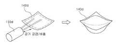
- 5A and 5Bare diagrams showing a configuration showing a third driving principle of the posture control device according to the present invention.
- the third driving principle of this embodimentuses the guide member 102a to process the linear posture control so that the inertial body 140a can move accordingly.
- the guide member 102amay be provided, for example, in a rail shape in which the inertial body 140a is movably coupled or in a cylindrical shape provided in the form of a pipe in which the inertial body 140a is movably inserted therein.
- the cylindrical guide member 102ais provided to allow the inertial body 140a to linearly move therein. On both sides of the cylindrical guide member 102a, the inertial body 140a can be moved in the other direction using compressed gas, and the inertial body 140a can also be moved by electronic control directly with a linear motor or the like.
- the inertial body 140amay move freely in the guide member 102a, and the inertial body 140a moves inside the guide member 102a using a fluid such as a spring, a motor, or a compressed gas. To control.
- the posture of the objectis controlled by using the impact generated by impacting the inertia body 140a by the acceleration to one end of the guide member 102a and the inertia thereof.
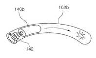
- the plurality of cylindrical guide members 102amay be disposed in the front and rear, left and right directions of the virtual reality wearable device 30 that has a shape suitable for the shape of the user's head and is worn on the user's head. ) Can be applied to simulate the impact and inertia by moving the inertia 140a in each of the directions in which the cylindrical guide member 102a is installed.
- FIGS. 6A and 6Bare views showing a configuration showing a fourth driving principle of the attitude control device according to the present invention.
- the fourth driving principle of this embodimentis a posture control method using magnetic field nerves, and a frequency (Hz) used when a magnetic field generated through a coil 140b through which electricity flows is applied to a nerve part.
- a frequency (Hz)used when a magnetic field generated through a coil 140b through which electricity flows is applied to a nerve part.
- virtual gravityis simulated by locally stimulating or suppressing nerve bundles using magnetic fields or stimulating or suppressing nerves of vestibular organs to stimulate brain nerves by using magnetic fields.
- our sense of gravitymeans that substances located inside the vestibular organs, located inside the ear, are physically moved by gravity, and these physical movements are converted into nerve signals that are transmitted to the brain.
- the virtual reality wearable device 30is experienced by stimulating or suppressing a neural part that transmits gravity, the virtual gravity produced to be suitable for the corresponding content may be delivered to the brain to maximize the experience effect.
- the magnetic field resolution and aiming positionare important for stimulating or suppressing the neural part that transmits gravity, so the following two methods are used. That is, since the shape of the magnetic field generated according to the shape and number of coils 140b generating the magnetic field and the arrangement of the coils 140b is different, an effective and local method of aiming using the coil 140b and the coil 140b may be used. Applied in several directions, each coil 140b generates a weaker stimulus than the threshold at which the nerve is stimulated. At this time, the overlapping part of the magnetic field generated by the plurality of coils 140b becomes a target nerve, that is, a target point, and each stimulus creates an additive effect to give a stimulus above a threshold.
- the resolution and the aiming point of the magnetic fieldare determined in such a manner as to overlap a part in the shape of the magnetic field generated by the plurality of coils 140b.
- Each magnetic field by the plurality of coils 140bhas an output that is less than the threshold for stimulating the nerve, and when superimposed, the magnetic field is stimulated beyond the threshold, and the non-overlapping nerves or cells are not affected. .
- the virtual reality wearable device 30 including the coil 140bis equipped with ultrasonic equipment (not shown) to find the position of the vestibular organ and the position of the nerve cell, and the angle of the coil 140b according to the position of the aiming point and It is applicable to adjust the direction. Therefore, the nerves and other cells in the parts where the magnetic fields do not overlap each other are not affected.
- attitude control device 100 of the present inventioncan be applied to various objects using the above-described driving principles.
- objectsinclude unmanned aerial vehicles, buildings, and virtual reality wearable devices.
- FIG. 7is a view showing a schematic configuration of an unmanned aerial vehicle to which the attitude control apparatus according to the first embodiment of the present invention is applied
- FIG. 8is a block diagram showing the configuration of the unmanned aerial vehicle shown in FIG. 7 is a view showing a configuration according to an embodiment of the inertial body shown in FIG. 7
- FIG. 10is a view showing a configuration according to another embodiment of the inertial body shown in FIG. 7,
- FIGS. 11A to 11Care FIG. 7. Figures for explaining the operation according to the attitude control of the unmanned aerial vehicle shown in.
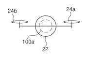
- the attitude control apparatus 100a of this embodimentis applied to the object of the unmanned aerial vehicle 20. That is, the unmanned aerial vehicle 20 of this embodiment is provided with, for example, a drone, and the attitude control device 100a is mounted at the center of gravity of the body portion 22.
- the unmanned aerial vehicle 20includes a plurality of propellers 24, a propeller driver 26 driving the propellers 24, and an attitude control device 100a.
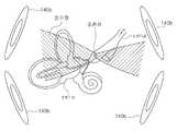
- the posture control device 100aincludes a physical information detector 110a, a controller 120a, an inertial driver 130a, and a control moment gyro 140a.
- the physical information detecting unit 110ais provided as a sensor for detecting physical information, for example, wind speed and air volume, of an external influence applied to the unmanned aerial vehicle 20.
- the controller 120acontrols the inertial body driver 130a in response to the physical information detected by the physical information sensor 110a.
- the inertial body driver 130adrives the control moment gyro 140a to adjust the attitude of the unmanned aerial vehicle 20 under the control of the controller 120a.
- the control moment gyro 140ais an inertial body and is rotated in at least two axes by the inertial driver 130a to adjust the attitude of the unmanned aerial vehicle 20.
- the control moment gyro 140amay be provided with at least two reaction wheels 142a to 142d.
- the reaction wheels 142a to 142dare provided on the top, bottom, left, and right sides corresponding to the plurality of axial directions.
- the reaction wheels 142c and 142d at the lower side and the right sidemay be provided as an option.
- Each of the reaction wheels 142a to 142dis provided with step motors 132a to 132d, and are rotated in the respective axial directions.
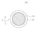
- control moment gyro 140ais provided with a reaction sphere actuator 150 in which a spherical inertia body and a motor are integrally formed.
- Reaction spherical actuatoris mounted on the surface of the sphere 152 and the case 154 surrounding the sphere 152, each with a plurality of permanent magnets and electromagnets as necessary, and by rotating the sphere in the desired direction in accordance with the operation of the electromagnet to torque Occurs.
- the unmanned aerial vehicle 20 of this embodimentis a control moment gyro 140a is mounted on the center of gravity of the unmanned aerial vehicle 20 in the form of a multi-axis wheel or sphere, and the drive mechanism of the propeller 24 of the unmanned aerial vehicle 20
- the direction and posturecan be adjusted independently.
- the drive mechanism of the propeller 24it is possible to change direction more quickly and attitude.
- itsince it is possible to maintain a fine posture in response to external factors, in particular, the wind, it can be applied to various uses, for example, an unmanned aerial vehicle for delivery.
- the propellers 24a and 24b of the unmanned aerial vehicle 20are all driven identically, and the attitude control device 100a rotates the attitude control device 100a in one direction to proceed in the other direction.
- the propeller 24a of the unmanned aerial vehicle 20is turned off, the other propeller 24b is turned on, and the attitude control device 100a is turned off.
- the attitude of the unmanned aerial vehicle 20can be adjusted to descend at a high speed in one downward direction.
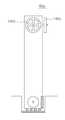
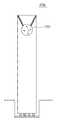
- FIG. 12is a diagram illustrating a schematic configuration of a building to which a posture control device according to a second embodiment of the present invention is applied, and FIGS. 13A and 13B illustrate a structure according to an embodiment of the posture control device shown in FIG. 12. Drawings.
- the attitude control device 100b of this embodimentis installed in the building 40. That is, in the building 40 of this embodiment, the attitude control apparatus 100b is installed in at least one of an upper part, an intermediate part, and a lower part.
- the posture control device 100bincludes a physical information detecting unit 110c such as an earthquake detecting sensor, a wind volume sensor, a reaction wheel or sphere inertial body 140c or 150, and a tuning mass damper 144.
- the attitude control device 100binstalls an inertial body 140c or 150 using the first or second driving principle in the building 40.
- a huge control moment gyro(140c or 150) is installed on the upper portion of the building (40a or 40b), large and small buildings due to external influences such as wind, earthquake ( By correcting the movement of 40a or 40b, fatigue failure of the building 40a or 40b can be reduced.
- the building 40a or 40bincreases, it is not only installed at the upper portion, but is also installed at the middle portion or the lower portion, and the building attitude control is optimized by interworking with the existing seismic design.
- control moment gyro 140c or 150may be installed at an upper portion thereof, and a tuned mass damper 144 may be provided at one side of the building 40.
- each of the various locations of the building 40is provided with a sensor for detecting the movement of the building 40 or a wind volume sensor for detecting the strength of the wind, through which the movement and the air volume of the building 40 is detected, and detected Corresponding mass and damper 144 to reduce the vibration and movement by installing a weight having a large weight, that is, an inertial body 150 in the upper portion corresponding to the movement and the amount of wind.
- Tuned Mass Damper 144is a type of reducer, for example, by using a natural mass of the building to be added to the building to suppress the vibration of the building or a spring mass meter having the same frequency as the natural frequency of the external force. It is mainly used for vibration control of buildings by wind or vibration. Therefore, in the present invention, the tuned mass damper (TMD) technology is mainly provided with a large-weight sphere shape, and by installing a control moment gyro of this sphere shape, additional and direct attitude control is possible.
- TMDtuned mass damper
- the building 40amay include a control moment gyro 140c in the form of a reaction wheel having a plurality of axes.
- the reaction wheelis rotated about at least two axes to control the attitude of the building 40a.
- the postures of the buildings 40: 40a and 40bare given by giving a movement to actively reverse the minute or large movements of the building by external elements such as wind. Control and minimize structural damage.
- the sensordetects the surplus movement buffered by the existing seismic design, and the reaction wheel or the control moment gyro 140c or 150 is located at the top or the bottom or various positions of the building 40 to actively construct the building 40.
- the external earthquake signal location, direction, and distanceare measured to predict the arrival time, waveform, and direction to the building 40, and control the posture to proactively respond to the earthquake. Can be.
- FIG. 14is a diagram illustrating a configuration of a virtual reality wearable device to which a posture control device according to a third embodiment of the present invention is applied
- FIG. 15is a diagram illustrating a configuration of an inertial body illustrated in FIG. 14.
- the virtual reality wearable device 30a of this embodimentincludes a posture control device using the above-described first to third driving principles and a magnetic field nerve control method for simulating gravity and external shock. .
- the virtual reality wearable device 30configures the main body 102 in the form of a user's head.
- a plurality of inertial bodies 140are provided on the side and driven by a shaft and a motor 130.
- the inertial body 140includes a plurality of coils, an electromagnetic drive, and a brake pad for electromagnetic driving.
- the inertial body 140may be provided as an air pressure pad 140d for haptic input, as shown in FIG. 15.
- the air pressure pad 140dis provided to expand and blow air by supplying air using an air pressure device 130d for supplying or discharging air to pressurize a site to which a stimulus or an impact is applied.
- the inertial body 140may be provided as a vibration pad (not shown) that transmits vibration using a vibration generation motor.
- FIG. 16is a diagram illustrating a configuration of a virtual reality wearable device to which a posture control device according to a fourth embodiment of the present invention is applied
- FIG. 17is a diagram illustrating a configuration of an inertial body illustrated in FIG. 16.
- the virtual reality wearable device 30b of this embodimentalso includes a posture control device that applies the above-described driving principles and the magnetic field nerve control method for gravity and shock simulation.
- the virtual reality wearable device 30bconfigures a main body in the form of a user's head.
- the inertial body 140is provided as a reaction wheel, and the reaction wheel 140 is rotated or stopped by the step motor 130 and the brake 132.
- the virtual reality wearable device 30bincludes, for example, a plurality of rotating inertia 140 positioned at both sides of the user's ear, front and rear of the head, and on the head of the user to generate torque through proper rotation and brake.
- a plurality of rotating inertia 140positioned at both sides of the user's ear, front and rear of the head, and on the head of the user to generate torque through proper rotation and brake.
- the virtual reality wearable devices 30a and 30bhave control moment gyros designed to fit the head shape and optimize the shape on both sides, front and back, and the top, and have reaction wheels or air pressure pads attached thereto. And by transmitting the torque generated according to the head to the head, the simulation of gravity and impact in the direction that matches the signal of the simulation or game in virtual reality can be achieved.
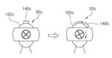
- FIG. 18is a diagram illustrating a configuration of a virtual reality wearable device to which a posture control device according to a fifth embodiment of the present invention is applied, and FIGS. 19A and 19B illustrate a configuration according to an embodiment of the inertial body illustrated in FIG. 18.
- 20is a diagram illustrating a configuration according to an embodiment of the inertial body illustrated in FIG. 19.
- the virtual reality wearable device 30c of this embodimentincludes a plurality of rails or pipes 102 provided with the inertial body 140 to move left and right, and is generated by the reaction wheel. According to the torque, the inertial body 140 is exaggeratedly moved in the desired direction so that the simulation of the virtual reality wearable device 30c can be realistically felt.
- the virtual reality wearable device 30c of this embodimentconfigures a main body in the form of a user's head.
- the bodyconsists of a plurality of rails or pipes 102.
- Each rail or pipe 102is installed on one side or inside so that the inertial body 140 is movable left and right.
- the rails or pipes 102: 102b, 102care provided in a straight or arc form 102b or 102c, as shown in FIGS. 18a and 18b, and are inertial bodies that can move along the rails or pipes 102. (140: 140b, 140c) by using the spring 142, linear motor or compressed air, respectively or mixed slowly or instantaneously in one direction to produce an effect similar to the reaction wheel or control moment gyro described above, The impact that 140 hits the end of the rail or pipe 102 may add an external impact effect.
- the above-described virtual reality wearable devices 30, 30a to 30chave, for example, a straight or streamlined pipe and are provided with a spherical or cylindrical inertial body having a certain weight inside the pipe, the inertial body moves quickly or rapidly.
- the impactis accelerated to one end of the pipe, the impact generated by the inertia and the impact is transmitted to the head, thereby enabling realistic simulation of gravity and external impact that is adapted to the virtual reality content.
- the virtual reality wearable device to which the posture control device of the present invention is appliedsubstantially rotates the head in an appropriate direction to maximize reality and immersion. Can be.
Landscapes
- Engineering & Computer Science (AREA)
- Aviation & Aerospace Engineering (AREA)
- Physics & Mathematics (AREA)
- General Physics & Mathematics (AREA)
- Radar, Positioning & Navigation (AREA)
- Remote Sensing (AREA)
- Automation & Control Theory (AREA)
- Toys (AREA)
Abstract
Description
Translated fromKorean본 발명은 자세 제어 장치에 관한 것으로, 좀 더 구체적으로 회전력을 전달하는 구동부와, 사용 목적에 따른 특정 무게를 가지는 적어도 하나의 관성체를 이용하여 바람, 충격 및 진동 등의 외부 영향으로부터 대상물의 무게 중심의 균형을 잡도록 자세를 조절하는 자세 제어 장치 및 그 방법에 관한 것이다.The present invention relates to a posture control device, and more specifically, the weight of an object from external influences such as wind, shock and vibration using a drive unit for transmitting rotational force and at least one inertial body having a specific weight according to the purpose of use. A posture control device and method for adjusting the posture to balance the center.
현재 자세 제어 기술은 다양한 종류의 대상물 예를 들어, 외부 영향으로 움직이는 자세에 영향을 받는 인공 위성, 건축물 등에 적용되어 외부 영향, 바람, 지진, 진동 등에 의해 발생되는 외부 영향으로부터 대상물의 자세를 제어하기 위한 기술이 점차 개발되고 있는 실정이다.Currently, posture control technology is applied to various kinds of objects, such as satellites and buildings which are affected by postures moving by external influences, to control the postures of objects from external influences generated by external influences, wind, earthquakes, vibrations, and the like. The technology for this is gradually being developed.
예를 들어, 건축물의 고층화에 따라, 바람이나 지진과 같은 횡하중에 의해 발생하는 진동의 제어는 고층 건축물 설계에 있어서 중요한 검토 사항이 되고 있다. 국내에서도 30층에서 60층 규모의 고층 건축물들이 다수 건설되고 있으며, 설계 단계에서 수평 방향의 사용성 검토가 의무화되어 있다. 사용성 조건을 만족시키지 못할 경우 이를 개선하기 위한 방법으로는 건축물의 강성을 증대시켜 건축물 자체를 강하게 설계하거나, 부가 장치를 설치하여 건축물의 감쇠력을 증대시키는 방법 등이 있다.For example, the control of vibration generated by lateral loads such as wind and earthquakes has become an important consideration in the design of high-rise buildings with the rise of buildings. In Korea, many high-rise buildings with 30 to 60 floors are being constructed, and horizontal usability review is mandatory at the design stage. If the usability condition is not satisfied, a method for improving this may be to increase the rigidity of the building to design the building itself strongly, or to install an additional device to increase the damping force of the building.
그러나 현재에는 건축물 자체의 강성 증대보다는 부가 장치에 의한 방법이 국외에서는 다수 채택되고 있으며, 국내에서는 이러한 방향으로 설계가 진행되지 않고 있는 실정이다.However, at present, a number of methods using additional equipment are adopted outside the building rather than increasing the rigidity of the building itself, and the design has not been progressed in this direction in Korea.
예컨대, 건축물의 진동을 제어하기 위한 대표적인 제진 장치로는 구조물에 질량체, 스프링 및 댐퍼로 구성된 진동체를 설치하는 동조 질량 댐퍼(Tuned Mass Damper : TMD) 방식이 있으며, 이미 미국, 일본 등에서 많이 사용되고 있다.For example, a representative vibration suppression device for controlling vibration of a building includes a tuned mass damper (TMD) method in which a vibrating body composed of a mass body, a spring, and a damper is installed on a structure, and is already widely used in the United States and Japan. .
또 우주 공간에서 지구 위를 선회하고 있는 인공 위성의 임무를 효율적으로 수행하기 위해서는 반드시 위성체의 자세를 안정하게 제어해야 한다. 특히, 궤도나 자세 기동 후의 자세 정확도의 유지와 다른 방향으로 그 자세를 바꾸는 것은 위성의 임무를 수행하는 데 있어서 선행적으로 수행되어야 할 부분이다.In addition, in order to efficiently perform the mission of the satellite orbiting the earth in space, the attitude of the satellite must be controlled stably. In particular, maintaining attitude accuracy after orbit or attitude maneuvering and changing its attitude in a different direction is a preliminary part of the mission of the satellite.
근래에 우주 공간에서의 위성의 임무 목적과 규모가 다양하고 커짐에 따라 유연한 구조물(flexible structures)을 갖는 인공 위성의 자세 제어의 중요성은 더욱 증가하고 있다. 인공 위성에 외부 교란이 있을 때 인공 위성의 자세를 제어해야 하는데, 강체로 가정하여 설계할 경우 자세 제어 시스템의 성능을 정확히 예측할 수 없게 되기 때문이다.In recent years, as the mission purpose and scale of the satellite in space increases and grows, the importance of attitude control of satellites having flexible structures is increasing. The attitude of the satellite must be controlled when the satellite has external disturbances, because the design of the rigid body assumes that the performance of the attitude control system cannot be accurately predicted.
상술한 바와 같이, 움직임이 가능한 다양한 대상물에 대해 발생되는 외부 영향으로 인한 대상물의 움직임을 보다 정확하게 조절하여 무게 중심을 잡도록 하는 자세 제어가 필요하다.As described above, a posture control is required to more accurately adjust the movement of an object due to external influences generated on various objects that can be moved to hold the center of gravity.
본 발명의 목적은 관성체를 이용하여 외부 영향에 따른 물리 정보에 대응하여 대상물의 자세를 제어하기 위한 자세 제어 장치 및 그 방법을 제공하는 것이다.It is an object of the present invention to provide a posture control device and a method for controlling a posture of an object in response to physical information according to external influences using an inertial body.
본 발명의 다른 목적은 다양한 구동 방식으로 다양한 대상물에 적용 가능하고, 해당 대상물의 자세를 제어하는 자세 제어 장치 및 그 방법을 제공하는 것이다.Another object of the present invention is to provide a posture control device and a method which can be applied to various objects by various driving methods and control the posture of the target object.
본 발명의 또 다른 목적은 가상 현실 웨어러블 기기의 효과적인 가상 현실감을 제공하기 위한 자세 제어 장치 및 그 방법을 제공하는 것이다.It is still another object of the present invention to provide a posture control device and method for providing an effective virtual reality of the virtual reality wearable device.
상기 목적들을 달성하기 위한, 본 발명의 자세 제어 장치는 반작용 휠, 제어 모멘트 자이로 및 이동 가능한 관성체 등을 이용하여 대상물의 자세 제어를 처리하는데 그 한 특징이 있다. 이와 같은 본 발명의 자세 제어 장치는 다양한 외부 영향에 따라 대상물의 정확한 자세 제어가 가능하다.In order to achieve the above objects, the posture control device of the present invention is characterized by processing the posture control of an object using a reaction wheel, a control moment gyro and a movable inertia. Such a posture control device of the present invention enables accurate posture control of an object according to various external influences.
이 특징에 따른 본 발명의 자세 제어 장치는; 대상물에 설치되는 본체와; 상기 본체에 설치되어 회전력을 발생하는 구동부와; 상기 대상물 자체 또는 외부로부터 발생되는 물리 정보를 감지하는 물리 정보 감지부와; 상기 본체에 설치되어 상기 구동부로부터 회전력을 전달받아서 회전되어 상기 대상물의 무게 중심을 조절하여 상기 대상물로 전달하는 적어도 하나의 관성체와; 상기 대상물의 현재 자세를 결정하고, 상기 물리 정보 감지부로부터 감지된 물리 정보에 대응하여 상기 관성체를 구동하도록 상기 구동부를 제어하는 제어부를 포함하여; 상기 관성체의 움직임에 의해 상기 대상물의 자세를 조절한다.The posture control device of the present invention according to this aspect; A main body installed on the object; A driving unit installed at the main body to generate a rotational force; A physical information sensor for sensing physical information generated from the object itself or from the outside; At least one inertial body installed on the main body and rotated by receiving a rotational force from the driving unit to adjust the center of gravity of the object and to transmit it to the object; A controller configured to determine a current posture of the object and control the driving unit to drive the inertial body in response to the physical information detected by the physical information sensing unit; The posture of the object is adjusted by the movement of the inertial body.
이 특징의 한 실시예에 있어서, 상기 본체는 상기 대상물의 형상에 대응하여 형성되고, 상기 관성체가 이동 가능하게 설치되는 레일, 파이프 중 어느 하나로 구비된다.In one embodiment of this aspect, the main body is formed corresponding to the shape of the object, and provided with any one of a rail and a pipe on which the inertial body is movable.
다른 실시예에 있어서, 상기 구동부는; 상기 관성체를 회전시키는 모터, 스텝 모터 및 정지기능을 갖는 모터 중 어느 하나로 구비된다.In another embodiment, the driving unit; It is provided with any one of a motor for rotating the inertial body, a step motor and a motor having a stop function.
또 다른 실시예에 있어서, 상기 물리 정보 감지부는 상기 대상물에 대응하여 풍속 및 진동 중 적어도 하나를 감지하는 센서로 구비된다.In another embodiment, the physical information sensor is provided as a sensor for detecting at least one of the wind speed and vibration corresponding to the object.
또 다른 실시예에 있어서, 상기 관성체는; 적어도 하나의 반작용 휠, 적어도 하나의 모멘트 휠 및 제어 모멘트 자이로 중 어느 하나로 구비된다.In another embodiment, the inertial body; At least one reaction wheel, at least one moment wheel, and a control moment gyro.
또 다른 실시예에 있어서, 상기 구동부와 상기 관성체가 일체로 구비되는 반응 구형 액추에이터로 구비된다.In another embodiment, the drive unit and the inertial body is provided with a reaction spherical actuator integrally provided.
본 발명의 다른 특징에 따르면, 자세 제어 장치의 제어 방법이 제공된다.According to another feature of the invention, a control method of the posture control device is provided.
이 특징에 따른 본 발명의 자세 제어 장치의 제어 방법은; 상기 자세 제어 장치가 대상물의 현재 자세를 결정하는 단계와; 상기 자세 제어 장치의 제어부가 현재 자세에 따른 관성체를 구동시켜서 상기 대상물의 자세를 유지하도록 하는 단계 및; 상기 자세 제어 장치의 물리 정보 감지부로부터 물리 정보가 감지되면, 감지된 물리 정보에 대응하여 상기 관성체를 구동하여 상기 대상물의 자세를 조절하는 단계;를 포함한다.The control method of the posture control device of the present invention according to this aspect; Determining, by the posture control device, a current posture of an object; Controlling, by the controller of the posture control device, to maintain the posture of the object by driving an inertial body according to a current posture; And adjusting the posture of the object by driving the inertial body in response to the sensed physical information when physical information is detected from the physical information sensor of the posture control device.
이 특징의 한 실시예에 있어서, 상기 조절하는 단계는; 상기 대상물이 무인 비행체인 경우, 적어도 2 개의 축을 중심으로 회전되는 원반 형태의 상기 관성체를 스텝 모터를 이용하여 회전시키고, 상기 관성체의 회전에 의해 생성되는 토크를 이용하여 상기 대상물의 자세를 제어하도록 처리한다.In one embodiment of this aspect, the adjusting step comprises; When the object is an unmanned aerial vehicle, the inertial body having a disk shape rotated about at least two axes is rotated by using a step motor, and the attitude of the object is controlled by using a torque generated by the rotation of the inertial body. Do it.
다른 실시예에 있어서, 상기 조절하는 단계는; 상기 대상물이 건축물인 경우, 적어도 2 개의 축을 중심으로 회전되는 원반 형태의 상기 관성체를 스텝 모터를 이용하여 회전시키고, 상기 관성체의 회전에 의해 생성되는 토크를 이용하여 상기 대상물의 자세를 제어하도록 처리하거나, 구 형태의 상기 관성체를 스텝 모터를 이용하여 회전시키고, 상기 관성체의 회전에 의해 생성되는 토크를 이용하여 상기 대상물의 자세를 제어하도록 처리한다.In another embodiment, the adjusting step; When the object is a building, the inertia in the form of a disk rotated about at least two axes is rotated using a step motor, and the attitude of the object is controlled by using the torque generated by the rotation of the inertia. Or the spherical inertial body is rotated using a step motor, and the attitude of the object is controlled using the torque generated by the rotation of the inertial body.
또 다른 실시예에 있어서, 상기 조절하는 단계는; 상기 대상물이 가상 현실 웨어러블 기기인 경우, 상기 관성체가 이동 가능하게 결합되는 가이드 부재를 이용하여 상기 관성체의 가감속 및 정지에 따라 발생된 토크를 머리로 전달하여, 가상 현실 상의 시뮬레이션 또는 상기 관성체의 이동 방향으로 중력 및 충격 시뮬레이션을 이룰 수 있도록 처리한다.In another embodiment, the adjusting step; When the object is a virtual reality wearable device, a torque generated according to acceleration and deceleration and stoppage of the inertia body is transferred to the head by using a guide member to which the inertia is movably coupled, thereby simulating or inertia in virtual reality. Handle to achieve gravity and impact simulation in the direction of travel.
또 다른 실시예에 있어서, 상기 조절하는 단계는; 상기 대상물이 가상 현실 웨어러블 기기인 경우, 전기가 흐르는 코일을 통해 발생되는 자기장을 신경 부위에 적용시키면 사용되는 주파수에 따라 신경을 자극하거나 억제시킬 수 있는 것을 이용하여 가상 중력을 시뮬레이션하도록 한다.In another embodiment, the adjusting step; When the object is a virtual reality wearable device, applying a magnetic field generated through a coil in which electricity flows to a nerve part may simulate virtual gravity by using a thing capable of stimulating or suppressing a nerve according to a frequency used.
상술한 바와 같이, 본 발명의 자세 제어 장치는 반작용 휠, 제어 모멘트 자이로 및 이동 가능한 관성체 등을 이용하여 대상물의 자세 제어를 처리함으로써, 다양한 외부 영향에 따라 대상물의 정확한 자세 제어가 가능하다.As described above, the posture control device of the present invention processes the posture control of the object using a reaction wheel, a control moment gyro, a movable inertia, and the like, thereby enabling accurate posture control of the object according to various external influences.
또 본 발명의 자세 제어 장치는 반작용 휠, 제어 모멘트 자이로 및 이동 가능한 관성체 등을 이용하여 다양한 대상물에 적용 가능하다.In addition, the posture control device of the present invention can be applied to various objects using a reaction wheel, a control moment gyro, and a movable inertial body.
또한 본 발명의 자세 제어 장치는 건축물에 적용하여 능동적인 자세 제어와 내진 설계가 가능하여 구조적인 피해를 최소화할 수 있다.In addition, the posture control device of the present invention can be applied to the building active posture control and seismic design can minimize the structural damage.
뿐만 아니라, 본 발명의 자세 제어 장치는 가상 현실 웨어러블 기기에 적용하여 3 차원적 방향으로 머리의 움직임을 계산하여 최적화된 중력 및 충격 시뮬레이션을 구현하여 현실감을 극대화할 수 있다.In addition, the posture control device of the present invention can be applied to the virtual reality wearable device to calculate the movement of the head in the three-dimensional direction to implement the optimized gravity and shock simulation to maximize the realism.
도 1은 본 발명에 따른 자세 제어 장치의 구성을 도시한 블럭도;1 is a block diagram showing the configuration of a posture control device according to the present invention;
도 2는 본 발명에 따른 자세 제어 장치의 제어 수순을 도시한 흐름도;2 is a flowchart showing a control procedure of the posture control device according to the present invention;
도 3a 및 도 3b는 본 발명에 따른 자세 제어 장치의 제 1 구동 원리를 나타내는 구성을 도시한 도면들;3A and 3B are views showing a configuration showing a first driving principle of the posture control device according to the present invention;
도 4는 본 발명에 따른 자세 제어 장치의 제 2 구동 원리를 나타내는 구성을 도시한 도면;4 is a view showing a configuration showing a second driving principle of the posture control device according to the present invention;
도 5a 및 도 5b는 본 발명에 따른 자세 제어 장치의 제 3 구동 원리를 나타내는 구성을 도시한 도면들;5A and 5B show a configuration showing a third driving principle of the attitude control apparatus according to the present invention;
도 6a 및 도 6b는 본 발명에 따른 자세 제어 장치의 제 4 구동 원리를 나타내는 구성을 도시한 도면들이다.6A and 6B are diagrams showing a configuration showing a fourth driving principle of the posture control device according to the present invention.
도 7은 본 발명의 제 1 실시예에 따른 자세 제어 장치가 적용된 무인 비행체의 개략적인 구성을 도시한 도면;7 is a view showing a schematic configuration of an unmanned aerial vehicle to which the attitude control apparatus according to the first embodiment of the present invention is applied;
도 8은 도 7에 도시된 무인 비행체의 구성을 나타내는 블럭도;8 is a block diagram showing the configuration of the unmanned aerial vehicle shown in FIG. 7;
도 9는 도 7에 도시된 관성체의 일 실시예에 따른 구성을 나타내는 도면;9 is a view showing a configuration according to an embodiment of the inertial body shown in FIG. 7;
도 10은 도 7에 도시된 관성체의 다른 실시예에 따른 구성을 나타내는 도면;10 is a view showing a configuration according to another embodiment of the inertial body shown in FIG. 7;
도 11a 내지 도 11c는 도 7에 도시된 무인 비행체의 자세 제어에 따른 동작을 설명하기 위한 도면들;11A to 11C are views for explaining an operation according to the attitude control of the unmanned aerial vehicle shown in FIG. 7;
도 12는 본 발명의 제 2 실시예에 따른 자세 제어 장치가 적용된 건축물의 개략적인 구성을 도시한 도면;12 is a diagram showing a schematic configuration of a building to which a posture control device according to a second embodiment of the present invention is applied;
도 13a 및 도 13b는 도 12에 도시된 자세 제어 장치의 실시예에 따른 구성을 나타내는 도면들;13A and 13B are views showing a configuration according to an embodiment of the attitude control device shown in FIG. 12;
도 14는 본 발명의 제 3 실시예에 따른 자세 제어 장치가 적용된 가상 현실 웨어러블 기기의 구성을 도시한 도면;14 is a diagram illustrating a configuration of a virtual reality wearable device to which a posture control device according to a third embodiment of the present invention is applied;
도 15는 도 14에 도시된 관성체의 실시예에 따른 구성을 나타내는 도면들;15 is a view showing a configuration according to an embodiment of the inertial body shown in FIG. 14;
도 16은 본 발명의 제 4 실시예에 따른 자세 제어 장치가 적용된 가상 현실 웨어러블 기기의 구성을 도시한 도면;16 is a diagram illustrating a configuration of a virtual reality wearable device to which the posture control device according to the fourth embodiment of the present invention is applied;
도 17은 도 16에 도시된 관성체의 실시예에 따른 구성을 나타내는 도면;17 is a view showing a configuration according to an embodiment of the inertial body shown in FIG. 16;
도 18은 본 발명의 제 5 실시예에 따른 자세 제어 장치가 적용된 가상 현실 웨어러블 기기의 구성을 도시한 도면;18 is a diagram illustrating a configuration of a virtual reality wearable device to which a posture control device according to a fifth embodiment of the present invention is applied;
도 19a 및 도 19b는 도 18에 도시된 관성체의 실시예에 따른 구성을 나타내는 도면들; 그리고19A and 19B are views showing a configuration according to an embodiment of the inertial body shown in FIG. 18; And
도 20은 도 19에 도시된 관성체의 실시예에 따른 구성을 나타내는 도면이다.20 is a diagram illustrating a configuration according to an embodiment of the inertial body illustrated in FIG. 19.
본 발명의 실시예는 여러 가지 형태로 변형될 수 있으며, 본 발명의 범위가 아래에서 서술하는 실시예로 인해 한정되어지는 것으로 해석되어서는 안된다. 본 실시예는 당업계에서 평균적인 지식을 가진 자에게 본 발명을 보다 완전하게 설명하기 위해서 제공되는 것이다. 따라서 도면에서의 구성 요소의 형상 등은 보다 명확한 설명을 강조하기 위해서 과장되어진 것이다.The embodiments of the present invention may be modified in various forms, and the scope of the present invention should not be interpreted as being limited by the embodiments described below. This embodiment is provided to more completely explain the present invention to those skilled in the art. Therefore, the shape of the components in the drawings, etc. have been exaggerated to emphasize a more clear description.
이하 첨부된 도 1 내지 도 20을 참조하여 본 발명의 실시예를 상세히 설명한다.Hereinafter, exemplary embodiments of the present invention will be described in detail with reference to FIGS. 1 to 20.
도 1은 본 발명에 따른 자세 제어 장치의 구성을 도시한 블럭도이다.1 is a block diagram showing the configuration of the posture control device according to the present invention.
도 1을 참조하면, 본 발명의 자세 제어 장치(100)는 다양한 종류의 관성체를 이용하여 외부 영향으로부터 물리 정보를 감지하고, 감지된 물리 정보에 대응하여 대상물의 움직임을 보상하도록 함으로써, 대상물의 자세를 제어하거나, 대상물로 가해지는 외부 영향에 대응되는 모멘트(moment)를 정확하게 사용자에게 전달하도록 처리한다.Referring to FIG. 1, the
이를 위해, 본 발명의 자세 제어 장치(100)는 대상물에 반영되는 다양한 외부 영향에 따라 발생되는 물리 정보를 감지하는 물리 정보 감지부(110)와, 물리 정보 감지부(110)로부터 감지된 물리 정보에 대응하여 대상물의 자세를 조절하도록 구동되는 관성체(140)와, 관성체(140)를 구동하는 구동부(130) 및, 물리 정보 감지부(110)로부터 감지된 물리 정보에 대응하여 관성체(140)가 대상물의 자세를 조절하거나, 물리 정보에 의해 대상물로 전달되는 모멘트를 사용자에게 전달하도록 구동부(130)를 제어하는 제어부(120)를 포함한다. 관성체(140)와 구동부(130)는 일체형(150)으로 구비될 수 있다.To this end, the
물리 정보 감지부(110)는 대상물 자체에서 발생되는 움직임이나 대상물로 가해지는 외부 영향 예를 들어, 바람, 지진에 의한 진동 등을 감지하는 적어도 하나의 센서로 구비된다. 또 물리 정보 감지부(110)는 사용자에게 전기적인 자극을 전달하도록 중력을 감지하는 센서로 구비될 수 있다.The physical
관성체(140)는 예를 들어, 반작용 휠, 모멘텀 휠, 제어 모멘트 자이로 등으로 구비되고, 자세 제어 장치(100)를 형성하는 몸체에 설치된다. 몸체는 예를 들어, 레일, 파이프 등으로 구비되어 대상물의 형상에 대응하는 구조로 대상물에 설치되고, 관성체(140)가 탑재되거나, 내부에 이동 가능하도록 수용 설치된다.The
구동부(130)는 예를 들어, 모터, 스텝 모터 및 정지기능을 갖는 모터 등으로 구비되어 관성체(140)를 회전 구동시키거나 정지시킨다.The driving
그리고 제어부(120)는 예를 들어, 컨트롤러, 프로세서, 프로그램어블 로직 컨트롤러(PLC), 컨트롤 유닛 등으로 구비되어, 물리 정보 감지부(110)로부터 감지된 물리 정보에 대응하여 구동부(130)를 제어한다.The
도 2는 본 발명에 따른 자세 제어 장치의 제어 수순을 도시한 흐름도이다.2 is a flowchart showing the control procedure of the posture control device according to the present invention.
도 2를 참조하면, 본 발명의 자세 제어 장치(100)는 단계 S160에서 대상물의 현재 자세를 결정하고, 단계 S170에서 현재 자세에 따른 관성체(140)를 구동시킨다. 단계 S180에서 물리 정보 감지부(110)로부터 물리 정보가 감지되면, 단계 S190에서 감지된 물리 정보에 대응하여 관성체(140)를 구동하여 대상물의 자세를 조절한다.Referring to FIG. 2, the
구체적으로 본 발명에서의 관성체를 구동하기 위한 구성 및 작용을 설명한다. 도 3a 및 도 3b는 본 발명에 따른 자세 제어 장치의 제 1 구동 원리를 나타내는 구성을 도시한 도면들이다.Specifically, the configuration and operation for driving the inertial body in the present invention will be described. 3A and 3B are diagrams showing the configuration showing the first driving principle of the posture control device according to the present invention.
도 3a 및 도 3b를 참조하면, 이 실시예의 제 1 구동 원리는 축을 중심으로 회전되는 원반 형태의 관성체(140) 즉, 회전체를 스텝 모터(130)를 이용하여 회전시키고, 이를 통해 생성되는 토크를 이용하여 대상물의 자세를 제어하도록 처리한다. 여기서 토크는 관성체(140)의 질량과 회전 속도에 의한 각 운동량에 의해 생성된다. 제 1 구동 원리를 위한 구성은 몸체(102)와, 각각의 축에 대응하여 구비되는 적어도 2 개의 관성체(140)와, 하나의 관성체(140)를 회전시키는 적어도 2 개의 스텝 모터(130) 및, 각 관성체(140)에 구비되어 회전을 정지시키는 브레이크(132)로 구성된다.3A and 3B, the first driving principle of this embodiment is to rotate a disk-shaped
이러한 제 1 구동 원리는 2 축 이상의 회전 구도가 발생되기 때문에 3 차원적인 자세 제어가 가능하다. 또 단순 회전에 의해 발생되는 토크 뿐만 아니라, 회전체(140)를 순간적으로 정지(브레이크)시키면, 정지에 의해 발생된 토크가 장착된 대상물로 전달되어 순간적인 움직임을 전달할 수 있다.This first driving principle enables three-dimensional attitude control because two or more axes of rotational composition are generated. In addition to the torque generated by the simple rotation, the momentary stop (break) of the
도 4는 본 발명에 따른 자세 제어 장치의 제 2 구동 원리를 나타내는 구성을 도시한 도면이다.4 is a view showing a configuration showing a second driving principle of the posture control device according to the present invention.
도 4를 참조하면, 이 실시예의 제 2 구동 원리는 회전 가능한 구 형태의 관성체 즉, 반응 구형 액추에이터(reaction sphere actuator)를 스텝 모터를 이용하여 회전시키고, 이를 통해 생성되는 토크를 이용하여 대상물의 자세를 제어하도록 처리한다. 제 2 구동 원리는 구 형태의 관성체와 모터가 결합된 일체형으로 제공된다. 따라서 구 형태의 관성체를 이용하여 축을 지나는 회전체를 단일화시킬 수 있다. 물론 회전체와 모터가 분리하여 외부에 모터를 구비하고, 이를 통해 회전체를 회전시키는 형태로 구비될 수도 있다.Referring to FIG. 4, the second driving principle of this embodiment is to rotate a spherical inertial body, that is, a reaction sphere actuator, by using a step motor, and by using the torque generated therefrom. Process to control posture. The second driving principle is provided in one piece in which a spherical inertial body and a motor are combined. Therefore, a spherical inertial body can be used to unify the rotating body passing through the axis. Of course, the rotor and the motor are separated from each other and provided with a motor, thereby rotating the rotor may be provided in the form.
여기서 반응 구형 액추에이터(reaction sphere actuator)는 복수 개의 영구 자석(Permanent Magnet : PM)을 구비하여 임의의 축을 중심으로 토크를 발생하는 로터(Rotor)와, 복수 개의 전자석(ElectroMagnet : EM)을 구비하여 영구 자석(PM)들과 상호 작용하여 자장을 형성하는 스테이터(Stator)로 구성된다. 로터와 스테이터는 볼 조인트 베이링(Ball Joint Bearing)에 의해 상호 회전 가능하게 지지된다. 이러한 반응 구형 액추에이터의 토크는 로터와 스테이터의 회전에 의해 즉, 구 표면과 구를 둘러싸고 있는 케이스에 각각의 영구 자석과 전자석을 필요에 따라 복수 개로 장착하고, 전자기석의 작동에 따라 원하는 방향으로 구를 회전시켜서 얻어진다.The reaction sphere actuator (reaction sphere actuator) is provided with a plurality of permanent magnets (PM) rotor to generate a torque around any axis (Rotor) and a plurality of electromagnets (ElectroMagnet: EM) It consists of a stator that interacts with the magnets PM to form a magnetic field. The rotor and the stator are rotatably supported by ball joint bearings. The torque of the reaction spherical actuator is based on the rotation of the rotor and the stator, that is, a plurality of permanent magnets and electromagnets are installed in the case surrounding the sphere surface and the sphere as necessary, and the sphere is moved in a desired direction according to the operation of the electromagnet. It is obtained by rotating.
이러한 제 2 구동 원리는 제 1 구동 원리와 동일하거나 대체로 유사한 방식으로 관성체를 구동시켜서 토크를 발생하고, 이에 대응하는 모멘트를 대상물로 전달되어 순간적인 움직임을 전달할 수 있다.This second driving principle may generate torque by driving an inertial body in the same or substantially similar manner as the first driving principle, and transmit a moment corresponding thereto to a momentary motion.
도 5a 및 도 5b는 본 발명에 따른 자세 제어 장치의 제 3 구동 원리를 나타내는 구성을 도시한 도면들이다.5A and 5B are diagrams showing a configuration showing a third driving principle of the posture control device according to the present invention.
도 5a 및 도 5b를 참조하면, 이 실시예의 제 3 구동 원리는 관성체(140a)가 따라서 움직일 수 있도록 가이드 부재(102a)를 이용하여 직선형의 자세 제어를 처리한다. 가이드 부재(102a)는 예를 들어, 관성체(140a)가 이동 가능하게 결합되는 레일이나, 관성체(140a)가 내부에 이동 가능하게 삽입되는 파이프 형태로 제공되는 실린더형 등으로 구비된다.5A and 5B, the third driving principle of this embodiment uses the
실린더형 가이드 부재(102a)는 내부에 관성체(140a)가 직선 이동할 수 있도록 제공된다. 실린더형 가이드 부재(102a)의 양측면에서 압축 가스를 사용하여 관성체(140a)를 타측 방향으로 이동시킬 수 있고, 관성체(140a)를 직선형 모터 등으로 직접 전자 제어하여 이동시킬 수도 있다.The
따라서 가이드 부재(102a)의 내부에 관성체(140a)가 자유롭게 이동할 수 있는 구조를 가지고, 스프링, 모터 또는 압축 가스 등의 유체를 이용하여 가이드 부재(102a)의 내부에서 관성체(140a)의 움직임을 제어한다. 관성체(140a)의 움직임에 의해 가이드 부재(102a)의 일측 끝단까지의 가속으로 부딪혀서 발생되는 충격 및 그 관성을 이용하여 대상물의 자세를 제어한다.Therefore, the
예를 들어, 대상물이 가상 현실 웨어러블 기기인 경우, 사용자의 머리 모양에 적합한 형상을 갖고 사용자의 머리에 착용되는 가상 현실 웨어러블 기기(30)에 전후, 좌우 방향 등으로 복수 개의 실린더형 가이드 부재(102a)를 적용하여, 실린더형 가이드 부재(102a)가 설치된 방향들 각각에 대해 관성체(140a)를 이동시켜서 충격 및 관성 시뮬레이션이 가능하다.For example, when the object is a virtual reality wearable device, the plurality of
도 6a 및 도 6b는 본 발명에 따른 자세 제어 장치의 제 4 구동 원리를 나타내는 구성을 도시한 도면이다.6A and 6B are views showing a configuration showing a fourth driving principle of the attitude control device according to the present invention.
도 6a 및 도 6b를 참조하면, 이 실시예의 제 4 구동 원리는 자기장 신경을 이용한 자세 제어 방식으로, 전기가 흐르는 코일(140b)을 통해 발생되는 자기장을 신경 부위에 적용시키면 사용되는 주파수(Hz)에 따라 신경을 자극하거나 억제시킬 수 있는 원리를 이용한다. 즉, 자기장을 이용하여 신경 다발을 국소적으로 자극하거나 억제시키거나, 자기장을 이용하여 뇌 신경을 자극하도록 전정 기관의 신경을 자극하거나 억제시켜서 가상 중력을 시뮬레이션한다.6A and 6B, the fourth driving principle of this embodiment is a posture control method using magnetic field nerves, and a frequency (Hz) used when a magnetic field generated through a
예를 들어, 우리가 중력을 느끼는 것은 귀의 안쪽에 위치한 전정 기관 내부에 위치하는 물질들이 중력에 의해 물리적으로 움직이고, 이 물리적 움직임이 신경 신호로 바뀌어 뇌로 전달된다. 중력을 전달하는 신경부를 자극 또는 억제시켜서 가상 현실 웨어러블 기기(30)의 체험 시, 해당 컨텐츠에 적합하게 제작된 가상 중력을 뇌로 전달하여 체험 효과의 극대화를 얻을 수 있다.For example, our sense of gravity means that substances located inside the vestibular organs, located inside the ear, are physically moved by gravity, and these physical movements are converted into nerve signals that are transmitted to the brain. When the virtual reality
이 때, 중력을 전달하는 신경부를 자극 또는 억제시키기 위해서는 자기장의 해상도와 조준 위치가 중요하므로, 다음 2 가지 방법을 혼용한다. 즉, 자기장을 발생시키는 코일(140b)의 모양과 갯수, 코일(140b)의 배치 구조에 따라 발생되는 자기장의 모양이 다르므로, 이를 이용하여 효과적이고 국소적인 조준하는 방법과, 코일(140b)을 여러 방향에서 적용하되, 각각의 코일(140b)은 신경이 자극되는 역치보다 약한 자극을 발생시킨다. 이 때, 다수의 코일(140b)이 발생시키는 자기장이 중첩되는 부분이 목표 신경 즉, 조준점(Target)이 되게 하고, 각각의 자극이 상가 효과(additive effect)를 만들어 역치 이상의 자극을 주게하는 방법을 혼용한다.At this time, the magnetic field resolution and aiming position are important for stimulating or suppressing the neural part that transmits gravity, so the following two methods are used. That is, since the shape of the magnetic field generated according to the shape and number of
이 경우, 복수 개의 코일(140b)들이 만들어내는 자기장의 모양에서 일부분을 겹치게 하는 방식으로 자기장의 해상도와 조준점(Target)을 결정한다. 복수 개의 코일(140b)들에 의한 각각의 자기장은 신경을 자극하는 역치에 못미치는 출력을 갖고 중첩되었을 때, 비로소 역치를 넘어 신경을 자극하게 되며, 겹치지 않는 부분의 신경이나 세포들은 영향을 받지 않는다.In this case, the resolution and the aiming point of the magnetic field are determined in such a manner as to overlap a part in the shape of the magnetic field generated by the plurality of
또 코일(140b)이 포함된 가상 현실 웨어러블 기기(30)에는 초음파 장비(미도시됨)가 탑재되어 전정 기관의 위치 및 신경 세포의 위치를 찾고, 조준점의 위치에 따라 코일(140b)의 각도 및 방향을 조절하도록 적용 가능하다. 그러므로 자기장이 서로 겹치지 않는 부분의 신경이나 다른 세포들에는 아무런 영향을 받지 않게 된다.In addition, the virtual reality
따라서 본 발명의 자세 제어 장치(100)는 상술한 구동 원리들을 이용하여 다양한 대상물에 적용 가능하다. 예를 들어, 대상물에는 무인 비행체, 건축물 및 가상 현실 웨어러블 기기 등이 포함된다.Therefore, the
즉, 도 7 내지 도 20을 이용하여 본 발명에 따른 자세 제어 장치가 적용된 대상물의 구성 및 작용에 대해 설명한다.That is, the configuration and operation of the object to which the posture control device according to the present invention is applied will be described with reference to FIGS. 7 to 20.
도 7은 본 발명의 제 1 실시예에 따른 자세 제어 장치가 적용된 무인 비행체의 개략적인 구성을 도시한 도면이고, 도 8은 도 7에 도시된 무인 비행체의 구성을 나타내는 블럭도이고, 도 9는 도 7에 도시된 관성체의 일 실시예에 따른 구성을 나타내는 도면이고, 도 10은 도 7에 도시된 관성체의 다른 실시예에 따른 구성을 나타내는 도면이며, 그리고 도 11a 내지 도 11c는 도 7에 도시된 무인 비행체의 자세 제어에 따른 동작을 설명하기 위한 도면들이다.7 is a view showing a schematic configuration of an unmanned aerial vehicle to which the attitude control apparatus according to the first embodiment of the present invention is applied, FIG. 8 is a block diagram showing the configuration of the unmanned aerial vehicle shown in FIG. 7 is a view showing a configuration according to an embodiment of the inertial body shown in FIG. 7, FIG. 10 is a view showing a configuration according to another embodiment of the inertial body shown in FIG. 7, and FIGS. 11A to 11C are FIG. 7. Figures for explaining the operation according to the attitude control of the unmanned aerial vehicle shown in.
도 7 내지 도 11c를 참조하면, 이 실시예의 자세 제어 장치(100a)는 무인 비행체(20)의 대상물에 적용된다. 즉, 이 실시예의 무인 비행체(20)는 예를 들어, 드론(drone)으로 구비되고, 몸체부(22)의 무게 중심부에 자세 제어 장치(100a)가 장착된다.7 to 11C, the
무인 비행체(20)는 복수 개의 프로펠러(24)와, 프로펠러(24)들을 구동하는 프로펠러 구동부(26) 및 자세 제어 장치(100a)를 포함한다. 자세 제어 장치(100a)는 물리 정보 감지부(110a)와, 제어부(120a)와, 관성체 구동부(130a) 및 제어 모멘트 자이로(140a)를 포함한다.The unmanned
이 실시예에서 물리 정보 감지부(110a)는 무인 비행체(20)에 가해지는 외부 영향에 대한 물리 정보 예를 들어, 풍속, 풍량 등을 감지하는 센서로 구비된다. 제어부(120a)는 물리 정보 감지부(110a)로부터 감지된 물리 정보에 대응하여 관성체 구동부(130a)를 제어한다. 관성체 구동부(130a)는 제어부(120a)의 제어를 받아서 무인 비행체(20)의 자세를 조절하도록 제어 모멘트 자이로(140a)를 구동한다. 그리고 제어 모멘트 자이로(140a)는 관성체로서, 관성체 구동부(130a)에 의해 적어도 2 축 방향으로 회전되어 무인 비행체(20)의 자세를 조절한다.In this embodiment, the physical
제어 모멘트 자이로(140a)는 도 9에 도시된 바와 같이, 적어도 2 개의 반작용 휠(142a ~ 142d)로 구비될 수도 있다. 이 실시예에서 반작용 휠(142a ~ 142d)은 복수 개의 축 방향에 대응하여 상하 좌우 각각에 구비된다. 이 때, 하부와 우측의 반작용 휠(142c, 142d)은 옵션으로 구비될 수 있다. 반작용 휠(142a ~ 142d)들 각각은 스텝 모터(132a ~ 132d)가 구비되고, 이를 통해 각 축 방향으로 회전된다.As shown in FIG. 9, the
또 제어 모멘트 자이로(140a)는 도 10에 도시된 바와 같이, 구 형태의 관성체와 모터가 일체형으로 형성된 반응 구형 액추에이터(150)로 구비된다. 반응 구형 액추에이터는 구(152) 표면과 구(152)를 둘러싸고 있는 케이스(154)에 각각의 영구 자석과 전자석을 필요에 따라 복수 개로 장착하고, 전자기석의 작동에 따라 원하는 방향으로 구를 회전시켜서 토크를 발생한다.In addition, as shown in FIG. 10, the
따라서 이 실시예의 무인 비행체(20)는 제어 모멘트 자이로(140a)가 다축 휠 형태 또는 구 형태로 무인 비행체(20)의 무게 중심부에 장착되고, 무인 비행체(20)의 프로펠러(24)의 구동 메커니즘과 독립적으로 방향 및 자세를 조절할 수 있다. 물론 프로펠러(24)의 구동 메커니즘과 연동하면, 더욱 신속한 방향 전환과 자세 조절이 가능하다. 또 외부 요소 특히, 바람의 영향에 대응하여 미세한 자세 유지가 가능하므로, 다양한 용도 예를 들어, 배달용 무인 비행체 등에 적용할 수 있다.Therefore, the unmanned
예를 들어, 도 11a에 도시된 바와 같이, 무인 비행체(20)의 프로펠러(24a, 24b)들은 모두 동일하게 구동시키고, 자세 제어 장치(100a)를 일측 방향으로 회전시켜서 타측 방향으로 진행하도록 자세 제어하거나, 도 11b 및 도 11c에 도시된 바와 같이, 무인 비행체(20)의 일측 프로펠러(24a)는 오프(OFF)시키고, 타측 프로펠러(24b)는 온(ON)시키고, 자세 제어 장치(100a)를 일측 방향으로 회전시켜서 일측 하향 방향으로 무인 비행체(20)를 빠른 속도로 하강하도록 자세 조절할 수 있다.For example, as shown in FIG. 11A, the
도 12는 본 발명의 제 2 실시예에 따른 자세 제어 장치가 적용된 건축물의 개략적인 구성을 도시한 도면이고, 도 13a 및 도 13b는 도 12에 도시된 자세 제어 장치의 실시예에 따른 구성을 나타내는 도면들이다.12 is a diagram illustrating a schematic configuration of a building to which a posture control device according to a second embodiment of the present invention is applied, and FIGS. 13A and 13B illustrate a structure according to an embodiment of the posture control device shown in FIG. 12. Drawings.
도 12 내지 도 13b를 참조하면, 이 실시예의 자세 제어 장치(100b)는 건축물(40)에 설치된다. 즉, 이 실시예의 건축물(40)은 상부, 중간부 및 하부 중 적어도 어느 한 곳에 자세 제어 장치(100b)가 설치된다. 자세 제어 장치(100b)는 지진 감지 센서, 풍량 센서 등과 같은 물리 정보 감지부(110c)와, 반작용 휠 또는 구 형태의 관성체(140c 또는 150)와, 동조 질량 댐퍼(144)를 포함한다. 이러한 자세 제어 장치(100b)는 제 1 또는 제 2 구동 원리를 이용하는 관성체(140c 또는 150)를 건축물(40)에 설치한다.12 to 13B, the attitude control device 100b of this embodiment is installed in the
이 실시예의 경우, 기존에는 건축물의 자세 제어 및 내진 설계를 위해 기존의 내진 설계에 의해 지진 시, 건축물의 움직임이 감소되었지만, 잉여 움직임이 존재하고, 또한 건축물들이 초고층화되면서 지진 이외에도 바람의 영향을 크게 받는다.In this embodiment, although the movement of the building is reduced during the earthquake by the existing earthquake design for the posture control and the seismic design of the building, there is a surplus movement and also the effect of the wind in addition to the earthquake as the buildings become high-rise. Receive loudly.
따라서 본 발명에서는 도 13a 또는 도 13b에 도시된 바와 같이, 건축물(40a 또는 40b)의 상부에 거대한 제어 모멘트 자이로(140c 또는 150)가 설치되고, 바람, 지진 등의 외부 영향에 의한 크고 작은 건축물(40a 또는 40b)의 움직임을 보정하여 건축물(40a 또는 40b)의 피로 파괴를 줄일 수 있다. 또한 건축물(40a 또는 40b)이 높아질수록 상부에만 설치되는 것이 아니라, 중간부나 하부에도 설치되어 기존의 내진 설계와 연동되어 최적화된 건축물 자세 제어가 가능하다.Therefore, in the present invention, as shown in Figure 13a or 13b, a huge control moment gyro (140c or 150) is installed on the upper portion of the building (40a or 40b), large and small buildings due to external influences such as wind, earthquake ( By correcting the movement of 40a or 40b, fatigue failure of the
또 상부에 제어 모멘트 자이로(140c 또는 150)를 설치하고, 건축물(40) 일측에 동조 질량 댐퍼(144)를 구비할 수 있다. 이 경우, 건축물(40)의 여러 위치 각각에 건축물(40)의 움직임을 감지하는 센서나 바람의 세기를 감지하는 풍량 센서를 구비하고, 이를 통해 건축물(40)의 움직임 및 풍량을 감지하고, 감지된 움직임 및 풍량에 대응하여 상부에 큰 무게를 갖는 추 즉, 관성체(150)를 설치하여 진동과 움직임을 줄이는 동조 질량 댐퍼(144)를 구비한다.In addition, the
동조 질량 댐퍼(Tuned Mass Damper)(144)는 예컨대, 흡진기의 일종으로, 건축물의 진동을 억제하기 위해서 건축물에 부가하는 건축물의 고유 진동수 또는 외력의 진동수와 고유 진동수가 같은 스프링 질량계 등을 이용하여 주로 바람이나 진동 등에 의한 건축물의 진동 제어에 사용된다. 따라서 본 발명에서 동조 질량 댐퍼(Tuned Mass Damper : TMD) 기술은 큰 무게의 구 형태가 주로 설치되는데, 이 구 형태의 제어 모멘트 자이로를 설치하여 추가적이고 직접적인 자세 제어가 가능하다.
또 건축물(40a)에 복수 개의 축을 가진 반작용 휠 형태의 제어 모멘트 자이로(140c)를 구비할 수 있다. 이 경우, 적어도 2 개의 축을 중심으로 반작용 휠이 회전되어 건축물(40a)의 자세를 제어한다.In addition, the
따라서 이 실시예는 건축물(40 : 40a, 40b)의 설계에 있어 바람 등의 외부 요소에 의한 건물의 미세한 혹은 큰 움직임을 능동적으로 역행하는 움직임을 부여하여 건축물(40 : 40a, 40b)의 자세를 제어하고 구조적 피해를 최소화할 수 있다.Therefore, in this embodiment, in the design of the buildings 40: 40a and 40b, the postures of the buildings 40: 40a and 40b are given by giving a movement to actively reverse the minute or large movements of the building by external elements such as wind. Control and minimize structural damage.
또 건축물(40 : 40a, 40b)의 높이별 가속도, 움직임의 거리, 실측 바람 속도, 온도, 습도, 지진파 도달량 및 파형 등을 분석하고 높이별로 다수 설치된 제어 모멘트 자이로(140c, 150)를 통해 자세를 제어한다.In addition, it analyzes the acceleration, the distance of movement, the measured wind speed, temperature, humidity, the amount of seismic waves and the waveform of the buildings (40: 40a, 40b) and postures through the control moment gyros (140c, 150) installed in multiple heights. To control.
특히, 지진 발생시 기존의 내진 설계에 의해 완충된 잉여 움직임을 센서가 감지하고 반작용 휠 또는 제어 모멘트 자이로(140c 또는 150)이 건축물(40)의 상단 혹은 하단 혹은 여러 위치에 위치하여 능동적으로 건축물(40)의 자세를 제어하여 피해를 최소화하여, 외부의 지진 신호 위치, 방향, 및 거리를 측정하여 건축물(40)까지의 도달 시간 및 파형 및 방향을 예측하고 자세를 제어하여 지진이 도달시 능동적으로 대처할 수 있다.In particular, when the earthquake occurs, the sensor detects the surplus movement buffered by the existing seismic design, and the reaction wheel or the
도 14는 본 발명의 제 3 실시예에 따른 자세 제어 장치가 적용된 가상 현실 웨어러블 기기의 구성을 도시한 도면이고, 도 15는 도 14에 도시된 관성체의 실시예에 따른 구성을 나타내는 도면들이다.FIG. 14 is a diagram illustrating a configuration of a virtual reality wearable device to which a posture control device according to a third embodiment of the present invention is applied, and FIG. 15 is a diagram illustrating a configuration of an inertial body illustrated in FIG. 14.
도 14 및 도 15를 참조하면, 이 실시예의 가상 현실 웨어러블 기기(30a)는 중력 및 외부 충격 시뮬레이션을 위해 상술한 제 1 내지 제 3 구동 원리들과 자기장 신경 제어 방법을 적용한 자세 제어 장치를 구비한다. 가상 현실 웨어러블 기기(30)는 사용자의 머리 형태로 본체(102)를 구성한다. 이 실시예의 자세 제어 장치는 복수 개의 관성체(140)가 측면에 구비되고, 샤프트와 모터(130)에 의해 구동된다. 관성체(140)는 도면에 도시되지 않았으나, 전자기 구동을 위한 복수 개의 코일들과 자석 및 브레이크 패드를 구비한다.14 and 15, the virtual reality
또 다른 예로서, 관성체(140)는 도 15에 도시된 바와 같이, 햅틱 입력을 위한 공기 압력 패드(140d)로 구비될 수 있다. 공기 압력 패드(140d)는 공기를 공급하거나 배출하는 공기 압력 장치(130d)를 이용하여 공기를 공급하여 팽창(blown up)시켜서 자극이나 충격을 가하는 부위를 가압할 수 있도록 제공된다. 또 다른 예로 관성체(140)는 진동 발생 모터(vibration moter)를 이용하여 진동을 전달하는 진동 패드(미도시됨)로 구비될 수도 있다.As another example, the
도 16은 본 발명의 제 4 실시예에 따른 자세 제어 장치가 적용된 가상 현실 웨어러블 기기의 구성을 도시한 도면이고, 도 17은 도 16에 도시된 관성체의 실시예에 따른 구성을 나타내는 도면이다.FIG. 16 is a diagram illustrating a configuration of a virtual reality wearable device to which a posture control device according to a fourth embodiment of the present invention is applied, and FIG. 17 is a diagram illustrating a configuration of an inertial body illustrated in FIG. 16.
도 16 내지 도 17을 참조하면, 이 실시예의 가상 현실 웨어러블 기기(30b) 또한 중력 및 충격 시뮬레이션을 위해 상술한 구동 원리들과 자기장 신경 제어 방법을 적용하는 자세 제어 장치를 구비한다. 가상 현실 웨어러블 기기(30b)는 사용자의 머리 형태로 본체를 구성한다. 관성체(140)는 반작용 휠로 구비되고, 반작용 휠(140)은 스텝 모터(130) 및 브레이크(132)에 의해 회전되거나 정지된다.16 to 17, the virtual reality
이러한 가상 현실 웨어러블 기기(30b)는 예컨대, 회전하는 복수 개의 관성체(140)가 사용자의 귀의 양옆, 머리의 앞뒤, 정수리 등에 위치하여, 적절한 회전과 브레이크를 통한 토크를 발생시키면, 그 더해진 토크의 방향과 크기값의 벡터값을 산출하여 모두 합하면, 원하는 3 차원적 방향이 만들어진다. 머리는 목을 기준으로 하여 움직이기 때문에 제어 모멘트 자이로를 통해 발생되는 토크의 방향을 조합하여 3 차원적 방향 즉, 벡터값과 머리의 움직임을 산출하고, 이를 통해 최적화된 중력 및 충격 시뮬레이션을 구현하여 현실감을 극대화할 수 있다.The virtual reality
따라서 가상 현실 웨어러블 기기(30a, 30b)는 양측면, 앞뒤, 그리고 상단에 머리 형태에 어울리고 형태가 최적화되어 맞게 디자인된 제어 모멘트 자이로, 반작용 휠 또는 공기 압력 패드 등이 부착되고, 이 관성체의 가감속 및 정지에 따라 발생된 토크를 머리로 전달하여, 가상 현실 상의 시뮬레이션 혹은 게임의 신호에 맞는 방향으로 중력 및 충격 시뮬레이션을 이룰 수 있다.Therefore, the virtual reality
그리고 도 18은 본 발명의 제 5 실시예에 따른 자세 제어 장치가 적용된 가상 현실 웨어러블 기기의 구성을 도시한 도면이고, 도 19a 및 도 19b는 도 18에 도시된 관성체의 실시예에 따른 구성을 나타내는 도면들이며, 도 20은 도 19에 도시된 관성체의 실시예에 따른 구성을 나타내는 도면이다.18 is a diagram illustrating a configuration of a virtual reality wearable device to which a posture control device according to a fifth embodiment of the present invention is applied, and FIGS. 19A and 19B illustrate a configuration according to an embodiment of the inertial body illustrated in FIG. 18. 20 is a diagram illustrating a configuration according to an embodiment of the inertial body illustrated in FIG. 19.
도 18 내지 도 20을 참조하면, 이 실시예의 가상 현실 웨어러블 기기(30c)는 관성체(140)가 좌우 이동 가능하도록 구비되는 복수 개의 레일 또는 파이프(102)가 구비되고, 반작용 휠에 의해 발생되는 토크에 따라 가상 현실 웨어러블 기기(30c)의 시뮬레이션을 현실감이 있게 느낄 수 있도록 관성체(140)가 과장되게 원하는 방향으로 이동된다.18 to 20, the virtual reality
이 실시예의 가상 현실 웨어러블 기기(30c)는 사용자의 머리 형태로 본체를 구성한다. 본체는 복수 개의 레일 또는 파이프(102)들로 이루어진다. 각각의 레일 또는 파이프(102)는 일측 또는 내부에 관성체(140)가 좌우 이동 가능하도록 설치된다.The virtual reality
또한, 레일 또는 파이프(102 : 102b, 102c)는 도 18a 및 도 18b에 도시된 바와 같이, 직선 또는 아크 형태(102b 또는 102c)로 구비되고, 레일 또는 파이프(102)를 따라 이동할 수 있는 관성체(140 : 140b, 140c)를 스프링(142), 직선형 모터 또는 압축 공기를 각각 혹은 혼용하여 한쪽 방향으로 서서히 또는 순간적으로 발사하여 상술한 반작용 휠 또는 제어 모멘트 자이로와 유사한 효과를 내고, 또한 관성체(140)가 레일 또는 파이프(102)의 끝에 부딪히는 충격을 통해 외부 충격 효과를 더할 수 있다.In addition, the rails or pipes 102: 102b, 102c are provided in a straight or
또한, 다수의 제어 모멘트 자이로 또는 반작용 휠과, 직선 또는 아크 형태의 관성체를 지닌 레일 또는 파이프의 역할을 혼용하여 효과를 극대화 할 수 있다. 예를 들면, 반작용 휠을 통하여 특정 방향으로의 토크를 출력시킴과 동시에 동일 방향으로 파이프 내의 관성체를 움직이고 또 충격시키면 더욱 극적인 효과를 전달할 수 있다.In addition, it is possible to maximize the effect by mixing the role of a plurality of control moment gyro or reaction wheel and a rail or pipe having a straight or arc inertial body. For example, if the inertia body in the pipe is moved and impacted in the same direction while outputting torque in a specific direction through the reaction wheel, a more dramatic effect can be transmitted.
상술한 가상 현실 웨어러블 기기(30, 30a ~ 30c)에는 예를 들어, 직선형 및 유선형 파이프가 장착되고 파이프 내부에 일정 무게를 갖는 구 또는 원기둥 형태의 관성체를 구비하면, 이 관성체가 빠르게 움직이거나 빠른 속도로 파이프의 일측끝까지 가속하여 부딪히면, 관성에 의한 움직임과 부딪혀서 발생되는 충격이 머리로 전달되기 때문에 가상 현실 컨텐츠에 맞춘 중력 및 외부 충격의 현실감있는 시뮬레이션이 가능하게 된다.If the above-described virtual reality
또한 제 1의 구동 원리의 제어 모멘트 자이로를 이용하여 발생되는 움직임과 제 2의 구동 원리를 통해 발생되는 움직임 및 충격을 복합적으로 사용하여 가상 현실의 현실적인 체험 효과를 극대화할 수 있다. 뿐만 아니라, 제 1 및 제 2의 구동 원리에 자기장 신경 제어를 동시에 사용하여 각 구동 원리의 효과를 극대화할 수도 있다. 예를 들어, 가상 현실 내의 게임에서, 우측에서 충격을 받는 컨텐츠를 제작할 때, 본 발명의 자세 제어 장치가 적용된 가상 현실 웨어러블 기기를 이용하여 실질적으로 머리를 적절한 방향으로 회전시켜 현실감과 몰입감을 극대화할 수 있다.In addition, it is possible to maximize the realistic experience effect of the virtual reality by using a combination of the motion generated by the control moment gyro of the first driving principle and the motion and shock generated by the second driving principle. In addition, magnetic field neural control may be simultaneously used for the first and second driving principles to maximize the effect of each driving principle. For example, in a game in virtual reality, when creating a shocked content on the right side, the virtual reality wearable device to which the posture control device of the present invention is applied substantially rotates the head in an appropriate direction to maximize reality and immersion. Can be.
이상에서, 본 발명에 따른 자세 제어 장치의 구성 및 작용을 상세한 설명과 도면에 따라 도시하였지만, 이는 실시예를 들어 설명한 것에 불과하며, 본 발명의 기술적 사상을 벗어나지 않는 범위 내에서 다양한 변화 및 변경이 가능하다.In the above, the configuration and operation of the posture control device according to the present invention have been shown according to the detailed description and drawings, but this is merely described by way of example, and various changes and modifications may be made without departing from the spirit of the present invention. It is possible.
Claims (2)
Translated fromKoreanApplications Claiming Priority (2)
| Application Number | Priority Date | Filing Date | Title |
|---|---|---|---|
| KR10-2016-0150925 | 2016-11-14 | ||
| KR1020160150925AKR101817878B1 (en) | 2016-11-14 | 2016-11-14 | Reaction control apparatus and method for controlling stability theerof |
Publications (1)
| Publication Number | Publication Date |
|---|---|
| WO2018088873A1true WO2018088873A1 (en) | 2018-05-17 |
Family
ID=61004211
Family Applications (1)
| Application Number | Title | Priority Date | Filing Date |
|---|---|---|---|
| PCT/KR2017/012879CeasedWO2018088873A1 (en) | 2016-11-14 | 2017-11-14 | Positioning control device and method therefor |
Country Status (2)
| Country | Link |
|---|---|
| KR (1) | KR101817878B1 (en) |
| WO (1) | WO2018088873A1 (en) |
Cited By (3)
| Publication number | Priority date | Publication date | Assignee | Title |
|---|---|---|---|---|
| TWI687650B (en)* | 2018-11-14 | 2020-03-11 | 財團法人工業技術研究院 | Localization and attitude estimation method using magnetic field and system thereof |
| CN111309038A (en)* | 2020-02-21 | 2020-06-19 | 南京航空航天大学 | Hybrid execution mechanism configuration optimization method based on TU cooperative game manipulation law |
| US20220049957A1 (en)* | 2019-04-02 | 2022-02-17 | Hewlett-Packard Development Company, L.P. | Gyroscope devices with control rotors and reaction wheels |
Citations (5)
| Publication number | Priority date | Publication date | Assignee | Title |
|---|---|---|---|---|
| US5754023A (en)* | 1995-10-26 | 1998-05-19 | Cybernet Systems Corporation | Gyro-stabilized platforms for force-feedback applications |
| JP2007261414A (en)* | 2006-03-28 | 2007-10-11 | Nec Corp | Automatic attitude control device, automatic attitude control method, and automatic attitude control program |
| JP2014178960A (en)* | 2013-03-15 | 2014-09-25 | Sony Corp | Acceleration sensation presentation device, acceleration sensation presentation method, and acceleration sensation presentation system |
| KR101579409B1 (en)* | 2014-12-26 | 2015-12-23 | 남승호 | Talk of vertical takeoff and landing aircraft-type propeller removal and balancing device Combination |
| KR101670736B1 (en)* | 2015-05-20 | 2016-11-03 | 한국과학기술연구원 | Apparatus and method for multimedia-interlocked brain stimulation for enhancing reality |
- 2016
- 2016-11-14KRKR1020160150925Apatent/KR101817878B1/enactiveActive
- 2017
- 2017-11-14WOPCT/KR2017/012879patent/WO2018088873A1/ennot_activeCeased
Patent Citations (5)
| Publication number | Priority date | Publication date | Assignee | Title |
|---|---|---|---|---|
| US5754023A (en)* | 1995-10-26 | 1998-05-19 | Cybernet Systems Corporation | Gyro-stabilized platforms for force-feedback applications |
| JP2007261414A (en)* | 2006-03-28 | 2007-10-11 | Nec Corp | Automatic attitude control device, automatic attitude control method, and automatic attitude control program |
| JP2014178960A (en)* | 2013-03-15 | 2014-09-25 | Sony Corp | Acceleration sensation presentation device, acceleration sensation presentation method, and acceleration sensation presentation system |
| KR101579409B1 (en)* | 2014-12-26 | 2015-12-23 | 남승호 | Talk of vertical takeoff and landing aircraft-type propeller removal and balancing device Combination |
| KR101670736B1 (en)* | 2015-05-20 | 2016-11-03 | 한국과학기술연구원 | Apparatus and method for multimedia-interlocked brain stimulation for enhancing reality |
Cited By (4)
| Publication number | Priority date | Publication date | Assignee | Title |
|---|---|---|---|---|
| TWI687650B (en)* | 2018-11-14 | 2020-03-11 | 財團法人工業技術研究院 | Localization and attitude estimation method using magnetic field and system thereof |
| US11536554B2 (en) | 2018-11-14 | 2022-12-27 | Industrial Technology Research Institute | Localization and attitude estimation method using magnetic field and system thereof |
| US20220049957A1 (en)* | 2019-04-02 | 2022-02-17 | Hewlett-Packard Development Company, L.P. | Gyroscope devices with control rotors and reaction wheels |
| CN111309038A (en)* | 2020-02-21 | 2020-06-19 | 南京航空航天大学 | Hybrid execution mechanism configuration optimization method based on TU cooperative game manipulation law |
Also Published As
| Publication number | Publication date |
|---|---|
| KR101817878B1 (en) | 2018-01-11 |
Similar Documents
| Publication | Publication Date | Title |
|---|---|---|
| CN106516182B (en) | Double five-degree-of-freedom air floatation master-slave non-contact double-super satellite ground principle verification system | |
| JP2500366B2 (en) | Three-dimensional free movement device | |
| US4908558A (en) | Spherical motion simulator | |
| JP6023326B2 (en) | 3D sphere drive system | |
| WO2018088873A1 (en) | Positioning control device and method therefor | |
| CN114625027B (en) | A ground-based full-physics simulation system for multi-spacecraft attitude and orbit control based on a multi-degree-of-freedom motion simulator | |
| US20160215765A1 (en) | Apparatus and Method for Gyroscopic Propulsion | |
| Kim et al. | Designing a low-cost spacecraft simulator | |
| CN113848751A (en) | Ground simulation system of drag-free spacecraft | |
| RU2412873C1 (en) | Method of orienting spacecraft purpose-designed hardware and device to this end | |
| CN106354030B (en) | Mars gravitation ground simulator and its analogy method | |
| Stingu et al. | Design and implementation of a structured flight controller for a 6DoF quadrotor using quaternions | |
| JP4942173B2 (en) | Non-contact type rigid body rotation control device | |
| da Silva et al. | A test-bed for attitude and determination control of spacecrafts | |
| CN102056797A (en) | Helicopter vibration control system and circular force generation system for canceling vibrations | |
| US20150122057A1 (en) | Apparatus and Method for Gyroscopic Propulsion | |
| Xiang et al. | A novel active suspension gravity compensation system for physically simulating human walking in microgravity | |
| CN106663386B (en) | Device for causing at least one person to move in space | |
| WO2017164677A1 (en) | Haptic actuator with linear and rotational movement | |
| CN110327632A (en) | A kind of virtual reality motion platform based on AGV kinematic system | |
| US10101157B2 (en) | Free-space force feedback system | |
| KR20220161864A (en) | control memet gyro base Drone | |
| CN114162355A (en) | Active compensation component of somatosensory micro-low gravity simulation device and simulation device | |
| KR20200040392A (en) | Drone | |
| RU2081458C1 (en) | Method for generation of varied acceleration for simulation of movement of vehicle and device which implements said method |
Legal Events
| Date | Code | Title | Description |
|---|---|---|---|
| 121 | Ep: the epo has been informed by wipo that ep was designated in this application | Ref document number:17870531 Country of ref document:EP Kind code of ref document:A1 | |
| NENP | Non-entry into the national phase | Ref country code:DE | |
| 122 | Ep: pct application non-entry in european phase | Ref document number:17870531 Country of ref document:EP Kind code of ref document:A1 |