WO2018087997A1 - Knee joint - Google Patents
Knee jointDownload PDFInfo
- Publication number
- WO2018087997A1 WO2018087997A1PCT/JP2017/031190JP2017031190WWO2018087997A1WO 2018087997 A1WO2018087997 A1WO 2018087997A1JP 2017031190 WJP2017031190 WJP 2017031190WWO 2018087997 A1WO2018087997 A1WO 2018087997A1
- Authority
- WO
- WIPO (PCT)
- Prior art keywords
- knee joint
- driven member
- linear motion
- crank mechanism
- knee
- Prior art date
- Legal status (The legal status is an assumption and is not a legal conclusion. Google has not performed a legal analysis and makes no representation as to the accuracy of the status listed.)
- Ceased
Links
Images


Classifications
- A—HUMAN NECESSITIES
- A61—MEDICAL OR VETERINARY SCIENCE; HYGIENE
- A61F—FILTERS IMPLANTABLE INTO BLOOD VESSELS; PROSTHESES; DEVICES PROVIDING PATENCY TO, OR PREVENTING COLLAPSING OF, TUBULAR STRUCTURES OF THE BODY, e.g. STENTS; ORTHOPAEDIC, NURSING OR CONTRACEPTIVE DEVICES; FOMENTATION; TREATMENT OR PROTECTION OF EYES OR EARS; BANDAGES, DRESSINGS OR ABSORBENT PADS; FIRST-AID KITS
- A61F2/00—Filters implantable into blood vessels; Prostheses, i.e. artificial substitutes or replacements for parts of the body; Appliances for connecting them with the body; Devices providing patency to, or preventing collapsing of, tubular structures of the body, e.g. stents
- A61F2/50—Prostheses not implantable in the body
- A61F2/60—Artificial legs or feet or parts thereof
- A61F2/64—Knee joints
- A—HUMAN NECESSITIES
- A61—MEDICAL OR VETERINARY SCIENCE; HYGIENE
- A61F—FILTERS IMPLANTABLE INTO BLOOD VESSELS; PROSTHESES; DEVICES PROVIDING PATENCY TO, OR PREVENTING COLLAPSING OF, TUBULAR STRUCTURES OF THE BODY, e.g. STENTS; ORTHOPAEDIC, NURSING OR CONTRACEPTIVE DEVICES; FOMENTATION; TREATMENT OR PROTECTION OF EYES OR EARS; BANDAGES, DRESSINGS OR ABSORBENT PADS; FIRST-AID KITS
- A61F2/00—Filters implantable into blood vessels; Prostheses, i.e. artificial substitutes or replacements for parts of the body; Appliances for connecting them with the body; Devices providing patency to, or preventing collapsing of, tubular structures of the body, e.g. stents
- A61F2/50—Prostheses not implantable in the body
- A61F2/68—Operating or control means
- A61F2/70—Operating or control means electrical
- A—HUMAN NECESSITIES
- A61—MEDICAL OR VETERINARY SCIENCE; HYGIENE
- A61F—FILTERS IMPLANTABLE INTO BLOOD VESSELS; PROSTHESES; DEVICES PROVIDING PATENCY TO, OR PREVENTING COLLAPSING OF, TUBULAR STRUCTURES OF THE BODY, e.g. STENTS; ORTHOPAEDIC, NURSING OR CONTRACEPTIVE DEVICES; FOMENTATION; TREATMENT OR PROTECTION OF EYES OR EARS; BANDAGES, DRESSINGS OR ABSORBENT PADS; FIRST-AID KITS
- A61F2/00—Filters implantable into blood vessels; Prostheses, i.e. artificial substitutes or replacements for parts of the body; Appliances for connecting them with the body; Devices providing patency to, or preventing collapsing of, tubular structures of the body, e.g. stents
- A61F2/50—Prostheses not implantable in the body
- A61F2/76—Means for assembling, fitting or testing prostheses, e.g. for measuring or balancing, e.g. alignment means
- A—HUMAN NECESSITIES
- A61—MEDICAL OR VETERINARY SCIENCE; HYGIENE
- A61F—FILTERS IMPLANTABLE INTO BLOOD VESSELS; PROSTHESES; DEVICES PROVIDING PATENCY TO, OR PREVENTING COLLAPSING OF, TUBULAR STRUCTURES OF THE BODY, e.g. STENTS; ORTHOPAEDIC, NURSING OR CONTRACEPTIVE DEVICES; FOMENTATION; TREATMENT OR PROTECTION OF EYES OR EARS; BANDAGES, DRESSINGS OR ABSORBENT PADS; FIRST-AID KITS
- A61F2/00—Filters implantable into blood vessels; Prostheses, i.e. artificial substitutes or replacements for parts of the body; Appliances for connecting them with the body; Devices providing patency to, or preventing collapsing of, tubular structures of the body, e.g. stents
- A61F2/50—Prostheses not implantable in the body
- A61F2002/5016—Prostheses not implantable in the body adjustable
- A—HUMAN NECESSITIES
- A61—MEDICAL OR VETERINARY SCIENCE; HYGIENE
- A61F—FILTERS IMPLANTABLE INTO BLOOD VESSELS; PROSTHESES; DEVICES PROVIDING PATENCY TO, OR PREVENTING COLLAPSING OF, TUBULAR STRUCTURES OF THE BODY, e.g. STENTS; ORTHOPAEDIC, NURSING OR CONTRACEPTIVE DEVICES; FOMENTATION; TREATMENT OR PROTECTION OF EYES OR EARS; BANDAGES, DRESSINGS OR ABSORBENT PADS; FIRST-AID KITS
- A61F2/00—Filters implantable into blood vessels; Prostheses, i.e. artificial substitutes or replacements for parts of the body; Appliances for connecting them with the body; Devices providing patency to, or preventing collapsing of, tubular structures of the body, e.g. stents
- A61F2/50—Prostheses not implantable in the body
- A61F2002/5072—Prostheses not implantable in the body having spring elements
- A61F2002/5073—Helical springs, e.g. having at least one helical spring
- A61F2002/5075—Multiple spring systems including two or more helical springs
- A—HUMAN NECESSITIES
- A61—MEDICAL OR VETERINARY SCIENCE; HYGIENE
- A61F—FILTERS IMPLANTABLE INTO BLOOD VESSELS; PROSTHESES; DEVICES PROVIDING PATENCY TO, OR PREVENTING COLLAPSING OF, TUBULAR STRUCTURES OF THE BODY, e.g. STENTS; ORTHOPAEDIC, NURSING OR CONTRACEPTIVE DEVICES; FOMENTATION; TREATMENT OR PROTECTION OF EYES OR EARS; BANDAGES, DRESSINGS OR ABSORBENT PADS; FIRST-AID KITS
- A61F2/00—Filters implantable into blood vessels; Prostheses, i.e. artificial substitutes or replacements for parts of the body; Appliances for connecting them with the body; Devices providing patency to, or preventing collapsing of, tubular structures of the body, e.g. stents
- A61F2/50—Prostheses not implantable in the body
- A61F2/68—Operating or control means
- A61F2002/6836—Gears specially adapted therefor, e.g. reduction gears
- A—HUMAN NECESSITIES
- A61—MEDICAL OR VETERINARY SCIENCE; HYGIENE
- A61F—FILTERS IMPLANTABLE INTO BLOOD VESSELS; PROSTHESES; DEVICES PROVIDING PATENCY TO, OR PREVENTING COLLAPSING OF, TUBULAR STRUCTURES OF THE BODY, e.g. STENTS; ORTHOPAEDIC, NURSING OR CONTRACEPTIVE DEVICES; FOMENTATION; TREATMENT OR PROTECTION OF EYES OR EARS; BANDAGES, DRESSINGS OR ABSORBENT PADS; FIRST-AID KITS
- A61F2/00—Filters implantable into blood vessels; Prostheses, i.e. artificial substitutes or replacements for parts of the body; Appliances for connecting them with the body; Devices providing patency to, or preventing collapsing of, tubular structures of the body, e.g. stents
- A61F2/50—Prostheses not implantable in the body
- A61F2/68—Operating or control means
- A61F2/70—Operating or control means electrical
- A61F2002/701—Operating or control means electrical operated by electrically controlled means, e.g. solenoids or torque motors
- A—HUMAN NECESSITIES
- A61—MEDICAL OR VETERINARY SCIENCE; HYGIENE
- A61F—FILTERS IMPLANTABLE INTO BLOOD VESSELS; PROSTHESES; DEVICES PROVIDING PATENCY TO, OR PREVENTING COLLAPSING OF, TUBULAR STRUCTURES OF THE BODY, e.g. STENTS; ORTHOPAEDIC, NURSING OR CONTRACEPTIVE DEVICES; FOMENTATION; TREATMENT OR PROTECTION OF EYES OR EARS; BANDAGES, DRESSINGS OR ABSORBENT PADS; FIRST-AID KITS
- A61F2/00—Filters implantable into blood vessels; Prostheses, i.e. artificial substitutes or replacements for parts of the body; Appliances for connecting them with the body; Devices providing patency to, or preventing collapsing of, tubular structures of the body, e.g. stents
- A61F2/50—Prostheses not implantable in the body
- A61F2/76—Means for assembling, fitting or testing prostheses, e.g. for measuring or balancing, e.g. alignment means
- A61F2002/7615—Measuring means
- A61F2002/7625—Measuring means for measuring angular position
- A—HUMAN NECESSITIES
- A61—MEDICAL OR VETERINARY SCIENCE; HYGIENE
- A61F—FILTERS IMPLANTABLE INTO BLOOD VESSELS; PROSTHESES; DEVICES PROVIDING PATENCY TO, OR PREVENTING COLLAPSING OF, TUBULAR STRUCTURES OF THE BODY, e.g. STENTS; ORTHOPAEDIC, NURSING OR CONTRACEPTIVE DEVICES; FOMENTATION; TREATMENT OR PROTECTION OF EYES OR EARS; BANDAGES, DRESSINGS OR ABSORBENT PADS; FIRST-AID KITS
- A61F2/00—Filters implantable into blood vessels; Prostheses, i.e. artificial substitutes or replacements for parts of the body; Appliances for connecting them with the body; Devices providing patency to, or preventing collapsing of, tubular structures of the body, e.g. stents
- A61F2/50—Prostheses not implantable in the body
- A61F2/76—Means for assembling, fitting or testing prostheses, e.g. for measuring or balancing, e.g. alignment means
- A61F2002/7615—Measuring means
- A61F2002/7645—Measuring means for measuring torque, e.g. hinge or turning moment, moment of force
- A—HUMAN NECESSITIES
- A61—MEDICAL OR VETERINARY SCIENCE; HYGIENE
- A61H—PHYSICAL THERAPY APPARATUS, e.g. DEVICES FOR LOCATING OR STIMULATING REFLEX POINTS IN THE BODY; ARTIFICIAL RESPIRATION; MASSAGE; BATHING DEVICES FOR SPECIAL THERAPEUTIC OR HYGIENIC PURPOSES OR SPECIFIC PARTS OF THE BODY
- A61H3/00—Appliances for aiding patients or disabled persons to walk about
- A61H2003/005—Appliances for aiding patients or disabled persons to walk about with knee, leg or stump rests
- A—HUMAN NECESSITIES
- A61—MEDICAL OR VETERINARY SCIENCE; HYGIENE
- A61H—PHYSICAL THERAPY APPARATUS, e.g. DEVICES FOR LOCATING OR STIMULATING REFLEX POINTS IN THE BODY; ARTIFICIAL RESPIRATION; MASSAGE; BATHING DEVICES FOR SPECIAL THERAPEUTIC OR HYGIENIC PURPOSES OR SPECIFIC PARTS OF THE BODY
- A61H3/00—Appliances for aiding patients or disabled persons to walk about
Definitions
- the present inventionrelates to a knee joint used for a prosthetic leg.
- a prosthetic legis composed of a socket that is fixed to the cut surface of the foot, a knee joint that is connected to the lower end of the socket, and a foot that is connected to the lower end of the knee joint and serves as a grounding portion.
- the knee jointcan be extended and bent within a predetermined angle range.
- knee joint drive systemsThere are three types of knee joint drive systems: passive, electronically controlled, and active.
- passive typethe wearer moves the prosthetic leg, and the knee joint passively bends / extends using a damper and a spring force of a hydraulic or pneumatic cylinder corresponding to the movement of the prosthetic leg.
- electronic control typemovement resistance in bending and extension of the knee joint is adjusted by electronic control so that the operation of the knee joint can be improved.
- An example of an electronically controlled knee jointis shown in Patent Document 1 below.
- the active typethe knee joint movement is actively controlled by using a motor to assist the knee joint movement during operations such as climbing stairs and standing up.
- the conventional active knee jointis not only expensive because of its complicated structure, but also has a problem that the wearer tends to get tired because of its heavy weight.
- the conventional active knee jointneeds to always operate a motor mounted on the knee joint, and is not energy efficient. Therefore, a battery having a large capacity is required and tends to be large and heavy.
- Non-Patent Document 1discloses an active knee joint that rotates a knee joint by converting a linear motion by a series elastic actuator (so-called “Series Elastic Actuator”) into a rotational motion by a pulley. .
- a series elastic actuatorso-called “Series Elastic Actuator”
- the walking energyis utilized to obtain a high energy efficiency as compared with the energy efficiency of a conventional active knee joint.
- a belt fixed to the linear motion elastic elementbecomes a mechanism for rotating the knee via two pulleys. Yes.
- Patent Document 2describes a configuration in which a knee member is rotatably attached to the upper end of the lower limb member and a foot member is attached to the lower end of the lower limb member.
- a protrusionis integrally formed on the side of the knee member, and a linear actuator is attached between the protrusion and the lower part of the lower limb member.
- the rotation of the knee membercan be assisted by the driving force of the linear actuator.
- the linear actuatoris directly connected to the knee member without a speed reducer, there is a problem that a high load is applied to the linear actuator when a high driving torque is to be obtained.
- the present inventionhas been made based on the above situation.
- the main object of the present inventionis to provide a knee joint that is energy efficient, is small and lightweight, and can take a wide range of motion.
- the series elastic mechanismincludes a driven member, an elastic member, and a linear member.
- the drive unitis configured to move the driven member,
- the elastic memberis disposed between the driven member and the linear member;
- the linear motion memberis configured to elastically move in at least one direction according to the movement of the driven member via the elastic member,
- the crank mechanismis configured to convert linear motion of the linear motion member into rotational motion.
- (Item 2)In addition, it has an upper connection for connecting the socket and knee joint, The knee joint according to item 1, wherein the crank mechanism is configured to rotationally move the upper connecting portion in a forward and reverse direction.
- the drive unitincludes a motor, a speed change mechanism, and a ball screw.
- the motoris configured to rotate the ball screw in forward and reverse directions via the speed change mechanism,
- the knee jointaccording to any one of items 1 to 4, wherein the driven member is configured to move linearly in response to rotation of the ball screw.
- the linear motion memberincludes a first contact portion and a second contact portion that are arranged to face each other with the driven member interposed therebetween,
- the elastic memberincludes a first spring and a second spring, The first spring is disposed between the first contact portion and the driven member;
- the knee jointaccording to any one of items 1 to 5, wherein the second spring is disposed between the second contact portion and the driven member.
- a knee jointthat is energy efficient, is small and lightweight, and can have a wide range of movement. Further, according to the present invention, it is possible to provide a knee joint that is active and relatively inexpensive.
- FIG. 3is a left side view of FIG. 2.
- FIG. 3is a plan view of FIG. 2.
- FIG. 4is a cross-sectional view taken along line AA in FIG. 3.
- FIG. 2is a perspective view of the knee joint of FIG. 1 with a cover attached.
- FIG. 7is a front view of FIG. 6.
- FIG. 8is a left side view of FIG. 7.
- FIG. 8is a plan view of FIG. 7. It is sectional drawing which follows the AA line of FIG.
- FIG. 2is a perspective view of the knee joint of FIG.
- FIG. 13is a left side view of FIG. 12.
- FIG. 13is a plan view of FIG. 12.
- FIG. 17is a front view of FIG. 16.
- It is a left view of FIG.It is a top view of FIG.
- It is sectional drawing which follows the AA line of FIG.It is a schematic explanatory drawing which shows the example which comprised the artificial leg using the knee joint of FIG. It is explanatory drawing for demonstrating operation
- FIG. 25is a graph showing an example of the characteristics of the crank mechanism of FIG. 24, in which the horizontal axis is the knee angle (degrees) and the vertical axis is the reduction ratio. It is a graph which shows the change of the knee angle at the time of walking, Comprising: A horizontal axis is time (arbitrary unit) and a vertical axis
- 27is a graph showing an example of the characteristic of the crank mechanism of FIG. 27 superimposed on the characteristic example of FIG. 25, in which the horizontal axis represents the knee angle (degrees) and the vertical axis represents the reduction ratio.
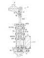
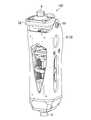
- FIGS. 1 to 10show a state in which a cover 51 (described later) of the frame 5 is excluded, and FIGS. 6 to 10 show a state in which the cover 51 is attached.
- the knee joint 100 according to the present embodimentcan be combined with a socket 200 and a foot portion 300 to constitute a prosthetic leg as shown in FIG. 21 (described later).
- a socket 200 and a foot portion 300to constitute a prosthetic leg as shown in FIG. 21 (described later).
- FIG. 21the structure of the knee joint 100 of this embodiment is demonstrated.
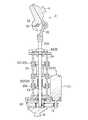
- the knee joint 100 of this embodimentincludes a drive unit 1, a series elastic mechanism 2, and a crank mechanism 3. Further, the knee joint 100 includes an upper connection portion 4, a frame 5, and a lower connection portion 6.
- the drive unit 1includes a motor 11, a speed change mechanism 12, and a ball screw 13 (see FIG. 5).
- the motor 11is configured to rotate the ball screw 13 in the forward and reverse directions via the speed change mechanism 12.
- the drive unit 1according to the present embodiment includes a battery (not shown), and can drive the motor 11 by power supply from the battery. However, the motor 11 may be driven by external power supply (for example, commercial power supply).
- the drive unit 1also includes a sensor (not shown) that detects the rotation angle of the crank mechanism 3 and a load on the motor 11, and can control the torque and rotation speed of the motor 11 according to the output of the sensor. It is like that.
- the motor 11, the speed change mechanism 12, and the ball screw 13 according to the present embodimentare supported by the frame 5 via appropriate attachment members or bearings.
- the series elastic mechanism 2includes a driven member 21, an elastic member 22, and a linear motion member 23. Further, the series elastic mechanism 2 of the present embodiment includes a guide shaft 24 for guiding the driven member 21 and the first and second abutting portions 231 and 232 of the linear motion member 23.
- the driven member 21is configured to be moved along the guide shaft 24 (in the vertical direction in FIG. 1) by the driving force of the driving unit 1. More specifically, the driven member 21 of the series elastic mechanism 2 in the present embodiment is configured to reciprocate in the linear direction according to the rotation of the ball screw 13 of the drive unit 1.
- the elastic member 22is disposed between the driven member 21 and the linear member 23. More specifically, the elastic member 22 of the present embodiment includes two first springs 221 and two second springs 222 (see FIGS. 1 and 3).
- the first spring 221is disposed between the first contact portion 231 (described later) of the linear motion member 23 and the driven member 21, but is not fixed to these members.
- the second spring 222is disposed between a second contact portion 232 (described later) of the linear motion member 23 and the driven member 21, but is not fixed to these members.
- the linear motion member 23is configured to move elastically in at least one direction through the elastic member 22 as the driven member 21 moves. More specifically, as described above, the linear motion member 23 of the present embodiment includes the first contact portion 231, the second contact portion 232, and the linear motion rod that are disposed to face each other with the driven member 21 interposed therebetween. 233. Moreover, the 1st contact part 231 and the 2nd contact part 232 are connected by the support
- the guide shaft 24is two in this embodiment, and is arranged to connect an upper base 52 and a lower base 53 (described later) of the frame 5 respectively. (See FIG. 2).
- the two guide shafts 24are not fixed to the driven member 21, the first contact portion 231, and the second contact portion 233, so that the driven member 21, the first contact portion 231, and the second contact shaft 23 are not fixed.
- the contact portion 233can move along the extending direction of the guide shaft 24 (that is, in the vertical direction in FIG. 2).
- the linear rod 233 of the linear member 23passes through the upper base 52 of the frame 5 and is fixed to the upper surface of the first contact portion 231 (see FIGS. 2 and 3). As the first contact portion 231 and the second contact portion 232 move, the guide shaft 24 reciprocates along the extending direction of the guide shaft 24 (that is, in the vertical direction in FIG. 1).
- crank mechanism 3is configured to convert linear motion of the linear motion member 23 into rotational motion.
- the crank mechanism 3according to the present embodiment includes a connecting rod 31, an arm member 32, and a rotating shaft 33.
- One end of the connecting rod 31is pin-coupled to the upper end of the linear motion rod 233 of the linear motion member 23 so as to be mutually rotatable.
- the arm member 32is pin-coupled to the other end of the connecting rod 31 so as to be mutually rotatable. Further, the arm member 32 can swing around the rotation shaft 33.
- the upper connection portion 4is attached to the upper portion of the arm member 32.
- the rotation shaft 33is attached to a cover 51 (described later) of the frame 5, and the relative position between the rotation shaft 33 and the frame 5 is fixed.
- the upper connecting portion 4is for connecting the socket 200 (see FIG. 21 described later) and the knee joint 100.
- the upper connecting portion 4is rotated in the forward and reverse directions by the crank mechanism 3 to realize the extension and bending operations of the artificial leg.
- the upper connection portion 4is also called a pyramid connector, and can be connected to the socket 200 using an existing method.
- the frame 5 of this embodimentincludes a cover 51 (see FIGS. 6 to 10), an upper base 52, and a lower base 53.
- the linear motion member 23is movable in at least one direction (specifically, in the vertical direction in FIG. 1) with respect to the upper and lower bases 52 and 53 of the frame 5.
- the rotating shaft 33 of the crank mechanism 3is supported by the cover 51 of the frame 5 in a rotatable state.
- the upper base 52 and the lower base 53are respectively fixed to the cover 51 so that they do not move relative to each other.
- the lower connection part 6is for connecting the knee joint 100 and the foot part 300 (see FIG. 21 described later).
- the lower connection portion 6is fixed to the lower base 53 of the frame 5.
- the lower connection portion 6is also called a pyramid connector, and can be connected to the foot portion 300 using an existing method.
- the extended state shown in FIG. 1is defined as the knee joint angle being 0 °.
- the operation of bending the knee joint angle to 60 ° from this statewill be described below.
- the motor 11 of the drive unit 1is rotated.
- the ball screw 13rotates through the speed change mechanism 12, and the driven member 21 of the series elastic mechanism 2 moves in one direction (downward in FIG. 1 in this example).
- the driven member 21applies a compressive force to the second spring 222 of the elastic member 22 and moves the linearly moving member 23 in one direction (downward in FIG. 1 in this example) via the spring.
- the connecting rod 31 of the crank mechanism 3is lowered, and as a result, the arm member 32 rotates about the rotation shaft 33 (see FIGS. 11 to 15).
- the upper connection part 4can be rotated by a desired angle.
- the knee angle in human walkingrepeats from 0 ° (extended state) to about 60 ° (bent state). Therefore, after the knee flexion of 60 °, the motor 11 is rotated in the reverse direction to apply a compressive force to the first spring 221 to return to the 0 ° extended state.
- the movement between the knee angle of 60 ° and 120 °is the movement when the user sits down, sits down, or the knee sits on the floor.
- the motordoes not operate in particular, but when standing up from the sitting state, assistance by the operation of the motor can be performed.
- FIGS. Examples of bending the knee joint at 60 ° or moreare shown in FIGS. As the arm member 32 of the crank mechanism 3 is further rotated in the same manner as described above, the knee joint can be bent to about 120 ° (ideally to about 140 °).
- the bending angle of the knee joint 100can be dynamically changed by appropriately controlling the torque, rotation speed, or rotation angle of the motor 11.
- the knee joint jointis actively controlled by the driving force of the driving unit 1 so that the behavior of the prosthetic leg user (walking or alternating stair climbing) Or standing-up motion).
- Non-Patent Document 1has the following problems. -The mechanism for converting the linear motion of the elastic mechanism into the rotational motion of the knee is very complex and has a large number of parts. So it gets heavier; ⁇ When the angle of movement of the knee joint is increased, the pulley becomes larger; ⁇ To prevent interference between the components (elastic elements) and the knee, it is necessary to place a pulley on the side of the prosthesis. Then, in order to maintain balance, it becomes necessary to use two pulley mechanisms (one pulley mechanism is composed of two pulleys, one connecting cable and related parts) in one artificial leg; ⁇ Pulley cables have problems in terms of durability, and maintenance costs tend to be high.
- crank mechanismSince the crank mechanism is used, even when the movable angle of the knee joint is widened, the increase in the size of the entire knee joint can be suppressed; -A small and lightweight crank mechanism can be used instead of the pulley mechanism, so that a small and lightweight artificial leg can be provided; -Since the crank mechanism is generally more durable than the pulley, it can exhibit the advantage that the maintenance cost can be kept low.
- the knee joint of the present embodimentis mounted on the user
- the lower end of the socket 200is connected to the upper connection part 4 of the knee joint 100
- the foot part 300is connected to the lower connection part 6 of the knee joint 100.
- the knee joint 100, the socket 200, and the foot portion 300constitute a prosthetic leg.
- an attachment(not shown) similar to the conventional one can be used.
- Fig. 22 (a)-(b)When the foot portion of the prosthetic leg lands on the floor surface, in the knee joint of the present embodiment, a downward pressing force is applied from the socket 200 to the linear motion member 23 via the crank mechanism 3.
- the first spring 221is elastically deformed and the energy is accumulated.
- the linear motion member 23is attached to the ball screw 13 via the driven member 21, the resistance to the movement of the driven member 21 is achieved by operating the motor in the direction opposite to the direction in which the ball screw is to rotate. A force can be generated, and energy in the elastic member 22 can be retained.
- the knee joint bend angle (passive) at the time of contact of the foot(FIGS. 22 (a) to (b)).
- the bending angle due to deformationcan be set to about 20 °. In this way, there is an advantage that it is possible to realize a knee flexion angle of about 20 ° for absorbing shock at the time of heel contact, and to improve the user's sense of use.
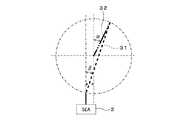
- crank mechanism 3 of the present embodimentwill be described in detail with further reference to FIGS.
- FIG. 23the structure of the above-described knee joint is schematically shown in FIG.
- the motor 11, the speed change mechanism 12, and the elastic member 22are shown as one actuator.
- the mechanism shown in FIG. 23is further schematically shown in FIG.
- each variable other than Kcan be regarded as a constant in the description here, so a detailed description is omitted.
- the deceleration variable K of the crank mechanismcan be expressed as follows.
- ⁇angle of the arm member 32 with respect to the vertical direction (vertical direction in FIG. 24); ⁇ : An angle of the connecting rod 31 with respect to the vertical direction (vertical direction in FIG. 24).
- the reduction ratio in the crank mechanismis as shown in FIG. 25 due to the influence of the deceleration variable K.
- FIG. 26shows an example of a change in knee angle over time associated with human walking.
- the knee anglechanges between about 0 ° and 80 ° during walking.
- the knee anglemay change greatly from a knee angle of approximately 80 ° to nearly 0 °.
- a large torqueis required to rotate the knee joint.
- a high reduction ratiocan be obtained at a deep knee angle of about 80 °. Then, there is an advantage that a large torque can be applied to the knee joint without imposing a large burden on the motor 11.
- the knee jointIn the case of a rush foot, the knee joint is required to have a high rotational speed at a shallow knee angle, but no high torque is required.
- the crank mechanism of the present embodimenthas an advantage that it is easy to increase the rotation speed of the knee joint because the reduction ratio is low when the knee angle is shallow (for example, 0 ° to 20 °).
- Non-Patent Document 1If a pulley mechanism (see Non-Patent Document 1 described above) is used instead of the crank mechanism, there is no reduction coefficient K in the pulley mechanism, so the reduction ratio in the pulley mechanism is constant regardless of the knee angle. Become. Therefore, when a large torque is required, there is a possibility that a large burden is generated on the motor. The same problem occurs even when the speed change mechanism is not used (see Patent Document 2 described above).
- the knee joint of the present embodimenthas an advantage that both high torque and high speed rotation can be achieved by using the crank mechanism.
- FIG. 27shows an example in which the offset amount between the rotation center of the crank mechanism 3 and the series elastic mechanism 2 is changed.
- the characteristics of the reduction ratio after changing the offset amountare shown by the solid line in FIG.
- a one-dot chain line in FIG. 28is a characteristic in the example of FIG.
- the relationship between the knee angle ⁇ and the reduction ratiocan be adjusted by changing the offset amount. Therefore, according to the present embodiment, there is an advantage that the maximum torque can be obtained at a necessary knee angle by adjusting the offset amount.
Landscapes
- Health & Medical Sciences (AREA)
- Transplantation (AREA)
- Vascular Medicine (AREA)
- Life Sciences & Earth Sciences (AREA)
- Oral & Maxillofacial Surgery (AREA)
- Engineering & Computer Science (AREA)
- Biomedical Technology (AREA)
- Heart & Thoracic Surgery (AREA)
- Veterinary Medicine (AREA)
- Cardiology (AREA)
- Animal Behavior & Ethology (AREA)
- General Health & Medical Sciences (AREA)
- Public Health (AREA)
- Orthopedic Medicine & Surgery (AREA)
- Prostheses (AREA)
- Rehabilitation Tools (AREA)
- Manipulator (AREA)
Abstract
Description
Translated fromJapanese本発明は、義足に用いられる膝継手に関するものである。The present invention relates to a knee joint used for a prosthetic leg.
一般に、義足は、足の切断面に固定されるソケットと、ソケットの下端に接続される膝継手と、膝継手の下端に接続されて接地部分となる足部とから構成される。膝継手は、膝関節と同様に、所定の角度範囲内で伸展及び屈曲ができるようになっている。Generally, a prosthetic leg is composed of a socket that is fixed to the cut surface of the foot, a knee joint that is connected to the lower end of the socket, and a foot that is connected to the lower end of the knee joint and serves as a grounding portion. Like the knee joint, the knee joint can be extended and bent within a predetermined angle range.
膝継手の駆動方式としては、受動式と、電子制御式と、能動式の3タイプが存在する。受動式では、装着者が義足を動かし、義足の移動に対応して、油圧や空圧シリンダーのダンパーとばね力などを用いて、受動的に膝継手が屈曲/伸展するようになっている。電子制御式では、膝継手の屈曲や伸展における移動抵抗を、電子制御により調整し、膝継手の動作を改善できるようになっている。電子制御式の膝継手の一例を下記特許文献1に示す。また、能動式では、モータを用いて能動的に膝継手の折れ曲がり角度を制御することにより、階段上りや立ち上がりなどの動作におけるひざ関節の動きを支援するようになっている。There are three types of knee joint drive systems: passive, electronically controlled, and active. In the passive type, the wearer moves the prosthetic leg, and the knee joint passively bends / extends using a damper and a spring force of a hydraulic or pneumatic cylinder corresponding to the movement of the prosthetic leg. In the electronic control type, movement resistance in bending and extension of the knee joint is adjusted by electronic control so that the operation of the knee joint can be improved. An example of an electronically controlled knee joint is shown in
ところで、従来の能動式の膝継手は、構造が複雑であるために高価であるばかりでなく、重いために装着者が疲労しやすいという問題があった。特に、従来の能動式の膝継手は、膝関節に搭載したモータを常に動作させる必要があり、エネルギー効率が良くないため、容量の大きいバッテリを必要とし、大きくかつ重くなる傾向があった。By the way, the conventional active knee joint is not only expensive because of its complicated structure, but also has a problem that the wearer tends to get tired because of its heavy weight. In particular, the conventional active knee joint needs to always operate a motor mounted on the knee joint, and is not energy efficient. Therefore, a battery having a large capacity is required and tends to be large and heavy.
一方、下記非特許文献1には、直列弾性アクチュエータ(いわゆる「Series Elastic Actuator」)による直動をプーリにより回転運動に変換して、膝継手を回動させる能動式の膝継手が示されている。この技術においては、直列弾性アクチュエータのバネを用いることにより、歩行エネルギーを活用して、従来の能動式の膝継手のエネルギー効率に比較して、高いエネルギー効率を得ている。しかしながら、この技術では、直列弾性アクチュエータの直動運動を膝の回転運動に変換するために、直動する弾性要素に固定されるベルトが二つのプーリを介して、膝を回転させる機構になっている。直動する弾性要素と膝との干渉を防ぐために、ベルトとプーリを膝継手の側面に配置する必要がある。すると、バランスを保つために、一本の膝継手において二つのベルトを用いる必要が生じてしまう。したがって、この技術では、機構が非常に複雑となり、部品数が多いという問題がある。膝継手の可動角度(可動範囲)を広げようとすると、ベルトとプーリが大型化してしまい、大きさや重さの点で使用しにくいものになってしまう。また、プーリを回転させるためのベルトは、耐久性の面で問題があるため、その維持や交換のためのコストが高くなりやすいという傾向がある。On the other hand, Non-Patent
また、下記特許文献2には、下肢部材の上端に膝部材を回転自在に取り付け、下肢部材の下端に足部材を取り付ける構成が記載されている。膝部材の側部には突出部が一体に形成されており、この突出部と下肢部材の下部との間にリニアアクチュエータが取り付けられている。この技術では、このリニアアクチュエータの駆動力により、膝部材の回転動作を補助できるようになっている。しかしながら、この技術では、リニアアクチュエータが膝部材に減速機なしで直結された構造のため、高い駆動トルクを得ようとしたときには、リニアアクチュエータに高い負荷がかかってしまうという問題がある。Also,
本発明は、前記した状況に基づいてなされたものである。本発明の主な目的は、エネルギー効率が良く、小型かつ軽量であり、しかも、可動範囲を広くとることが可能な膝継手を提供することである。The present invention has been made based on the above situation. The main object of the present invention is to provide a knee joint that is energy efficient, is small and lightweight, and can take a wide range of motion.
前記した課題を解決する手段は、以下の項目のように記載できる。The means for solving the above-described problems can be described as the following items.
(項目1)
駆動部と、直列弾性機構と、クランク機構とを備えており、
前記直列弾性機構は、従動部材と、弾性部材と、直動部材とを備えており、
前記駆動部は、前記従動部材を移動させる構成となっており、
前記弾性部材は、前記従動部材と前記直動部材との間に配置されており、
前記直動部材は、前記弾性部材を介して、前記従動部材の移動に従って、少なくとも一方向に弾性的に移動する構成となっており、
前記クランク機構は、前記直動部材の直線運動を回転運動に変換する構成となっている 膝継手。(Item 1)
A drive unit, a series elastic mechanism, and a crank mechanism;
The series elastic mechanism includes a driven member, an elastic member, and a linear member.
The drive unit is configured to move the driven member,
The elastic member is disposed between the driven member and the linear member;
The linear motion member is configured to elastically move in at least one direction according to the movement of the driven member via the elastic member,
The crank mechanism is configured to convert linear motion of the linear motion member into rotational motion.
(項目2)
さらに、ソケットと膝継手とを接続するための上部接続部を備えており、
前記クランク機構は、前記上部接続部を正逆方向に回転運動させる構成となっている
項目1に記載の膝継手。(Item 2)
In addition, it has an upper connection for connecting the socket and knee joint,
The knee joint according to
(項目3)
さらにフレームを備えており、
前記直動部材は、前記フレームに対して少なくとも一方向に沿って移動可能とされている
項目1又は2に記載の膝継手。(Item 3)
It also has a frame,
The knee joint according to
(項目4)
さらにフレームを備えており、
前記クランク機構の回転軸は、前記フレームにより支持されている
項目1又は2に記載の膝継手。(Item 4)
It also has a frame,
(項目5)
前記駆動部は、モータと、変速機構と、ボールねじとを備えており、
前記モータは、前記変速機構を介して、前記ボールねじを正逆方向に回転させる構成となっており、
前記従動部材は、前記ボールねじの回転に応じて直動する構成となっている
項目1~4のいずれか1項に記載の膝継手。(Item 5)
The drive unit includes a motor, a speed change mechanism, and a ball screw.
The motor is configured to rotate the ball screw in forward and reverse directions via the speed change mechanism,
The knee joint according to any one of
(項目6)
前記直動部材は、前記従動部材を挟んで対向して配置された第1当接部と第2当接部とを備えており、
前記弾性部材は、第1ばねと第2ばねとを備えており、
前記第1ばねは、前記第1当接部と前記従動部材との間に配置されており、
前記第2ばねは、前記第2当接部と前記従動部材との間に配置されている
項目1~5のいずれか1項に記載の膝継手。(Item 6)
The linear motion member includes a first contact portion and a second contact portion that are arranged to face each other with the driven member interposed therebetween,
The elastic member includes a first spring and a second spring,
The first spring is disposed between the first contact portion and the driven member;
The knee joint according to any one of
(項目7)
項目1~6のいずれか1項に記載の膝継手を備える義足。(Item 7)
An artificial leg comprising the knee joint according to any one of
本発明によれば、エネルギー効率がよく、小型かつ軽量でかつ可動範囲を広くとることが可能な膝継手を提供することが可能となる。また、本発明によれば、能動型でありながら比較的に安価な膝継手を提供することが可能になる。According to the present invention, it is possible to provide a knee joint that is energy efficient, is small and lightweight, and can have a wide range of movement. Further, according to the present invention, it is possible to provide a knee joint that is active and relatively inexpensive.
以下、本発明の一実施形態に係る膝継手を、添付の図面(図1~図10)を参照しながら説明する。なお、これらの図のうち、図1~5は、フレーム5のカバー51(後述)を除外した状態を示し、図6~10は、カバー51を取り付けた状態を示している。Hereinafter, a knee joint according to an embodiment of the present invention will be described with reference to the accompanying drawings (FIGS. 1 to 10). Of these drawings, FIGS. 1 to 5 show a state in which a cover 51 (described later) of the
本実施形態の膝継手100は、図21(後述)に示すように、ソケット200及び足部300と組み合わされて、義足を構成できるようになっている。以下、本実施形態の膝継手100の構成について説明する。The knee joint 100 according to the present embodiment can be combined with a
(本実施形態の構成)
本実施形態の膝継手100は、駆動部1と、直列弾性機構2と、クランク機構3とを備えている。さらに、この膝継手100は、上部接続部4と、フレーム5と、下部接続部6とを備えている。(Configuration of this embodiment)
The
(駆動部)
駆動部1は、モータ11と、変速機構12と、ボールねじ13とを備えている(図5参照)。モータ11は、変速機構12を介して、ボールねじ13を正逆方向に回転させる構成となっている。本実施形態の駆動部1は、バッテリ(図示せず)を備えており、バッテリからの給電によってモータ11を駆動できるようになっている。ただし、外部給電(例えば商用電源)によりモータ11を駆動する構成とすることも可能である。また、駆動部1は、クランク機構3の回転角度やモータ11への負荷を検出するセンサ(図示せず)を備えており、そのセンサの出力に応じてモータ11のトルクや回転速度を制御できるようになっている。本実施形態のモータ11、変速機構12、及びボールねじ13は、フレーム5により、適宜の取付部材あるいは軸受けを介して支持されている。(Drive part)
The
(直列弾性機構)
直列弾性機構2は、従動部材21と、弾性部材22と、直動部材23とを備えている。また、本実施形態の直列弾性機構2は、従動部材21と、直動部材23の第1・第2当接部231・232とを案内するためのガイドシャフト24を備えている。(Series elastic mechanism)
The series
従動部材21は、駆動部1の駆動力によって、ガイドシャフト24に沿って(図1において上下方向に)移動させられる構成となっている。より具体的には、本実施形態における直列弾性機構2の従動部材21は、駆動部1のボールねじ13の回転に応じて、直線方向に往復動する構成となっている。The driven
弾性部材22は、従動部材21と直動部材23との間に配置されている。より具体的には、本実施形態の弾性部材22は、2本の第1ばね221と2本の第2ばね222とを備えている(図1及び図3参照)。第1ばね221は、直動部材23の第1当接部231(後述)と従動部材21との間に配置されているが、これらの部材には固定されていない状態となっている。第2ばね222は、直動部材23の第2当接部232(後述)と従動部材21との間に配置されているが、これらの部材には固定されていない状態となっている。The
直動部材23は、弾性部材22を介して、従動部材21の移動に従って、少なくとも一方向に弾性的に移動する構成となっている。より具体的には、前記したように、本実施形態の直動部材23は、従動部材21を挟んで対向して配置された第1当接部231と第2当接部232と直動ロッド233とを備えている。また、第1当接部231と第2当接部232とは、支柱234により連結されている(図3参照)。支柱234は、従動部材21を貫通しており、両者間での相対移動は可能となっている。さらに、支柱234は、弾性部材22の第1ばね221及び第2ばね222の内側をそれぞれ通過する状態で配置されている。本例では、直動ロッド233の下端と、支柱234の上端とは、連結されており、これらは一体の部品となっている。The
ガイドシャフト24は、本実施形態では2本とされており、それぞれ、フレーム5の上部基台52と下部基台53(後述)とを連結するように配置されている。(図2参照)。2本のガイドシャフト24は、従動部材21と第1当接部231と第2当接部233とには固定されておらず、これにより、従動部材21と第1当接部231と第2当接部233とは、ガイドシャフト24の延長方向に沿って(すなわち図2において上下方向に)移動できるようになっている。The
直動部材23の直動ロッド233は、本実施形態では、フレーム5の上部基台52を貫通して、第1当接部231の上面に固定されており(図2及び図3参照)、第1当接部231及び第2当接部232の移動に従って、ガイドシャフト24の延長方向に沿って(つまり図1において上下方向に)往復動するようになっている。In this embodiment, the
(クランク機構)
クランク機構3は、直動部材23の直線運動を回転運動に変換する構成となっている。本実施形態のクランク機構3は、連結ロッド31とアーム部材32と回転軸33とを備えている。(Crank mechanism)
The
連結ロッド31の一端は、直動部材23の直動ロッド233の上端に、相互に回転可能となるようにピン結合されている。One end of the connecting
アーム部材32は、連結ロッド31の他端に、相互に回転可能となるようにピン結合されている。また、アーム部材32は、回転軸33を中心として揺動可能とされている。アーム部材32の上部には、上部接続部4が取り付けられている。The
回転軸33は、本実施形態では、フレーム5のカバー51(後述)に取り付けられており、回転軸33とフレーム5との間の相対位置が固定されている。In this embodiment, the
(上部接続部)
上部接続部4は、ソケット200(後述の図21参照)と膝継手100とを接続するためのものである。上部接続部4は、クランク機構3により、正逆方向に回転運動することによって、義足の伸展・屈曲の動作を実現する。上部接続部4は、ピラミッドコネクタとも呼ばれており、既存の手法を用いてソケット200に接続できるようになっている。(Upper connection part)
The upper connecting
(フレーム)
本実施形態のフレーム5は、カバー51(図6~図10参照)と、上部基台52と、下部基台53とを備えている。本実施形態においては、直動部材23は、前記フレーム5の上下の基台52・53に対して少なくとも一方向に(具体的には図1において上下方向に)移動可能とされている。また、本実施形態においては、前記したように、クランク機構3の回転軸33が、フレーム5のカバー51により、回転可能な状態で支持されている。さらに上部基台52と下部基台53は、それぞれ、カバー51に対して固定されており、相対移動しないようになっている。(flame)
The
(下部接続部)
下部接続部6は、膝継手100と足部300(後述の図21参照)とを接続するためのものである。下部接続部6は、フレーム5の下部基台53に固定されている。下部接続部6も、ピラミッドコネクタとも呼ばれており、既存の手法を用いて足部300と接続できるようになっている。(Lower connection part)
The
(本実施形態の動作)
次に、図11~図22をさらに参照して、本実施形態の膝継手100の動作を説明する。(Operation of this embodiment)
Next, the operation of the
(膝継手の角度調整動作…0°から60°)
本実施形態の説明においては、図1に示す伸展状態を、膝継手の角度が0°であると定義する。この状態から膝継手の角度を60°に屈曲する動作を以下に説明する。(Knee joint angle adjustment operation: 0 ° to 60 °)
In the description of the present embodiment, the extended state shown in FIG. 1 is defined as the knee joint angle being 0 °. The operation of bending the knee joint angle to 60 ° from this state will be described below.
まず、駆動部1のモータ11を回転させる。すると、変速機構12を介してボールねじ13が回転し、直列弾性機構2の従動部材21が一方向(本例では図1において下方向)に移動する。First, the
すると、従動部材21は、弾性部材22の第2ばね222に圧縮力を加えて、これのばねを介して、直動部材23を一方向(本例では図1において下方向)に移動させる。直動部材23がばね力により下降すると、クランク機構3の連結ロッド31が下降し、その結果、アーム部材32が回転軸33を中心として回転する(図11~図15参照)。これにより、上部接続部4を所望の角度だけ回転させることができる。人間の歩行におけるひざの角度は、0°(伸長状態)から約60°(屈曲状態)までを繰り返す。したがって、60°の膝屈曲の後は、モータ11を逆回転させて、第1ばね221に圧縮力を加えることにより、0°の伸展状態に戻す。Then, the driven
(膝継手の角度調整動作…60°~120°)
膝の角度が60°から120°までの間の動作は、使用者が座ったり、正座したり、膝が床に着いたりするときの動作である。座る際は、特にモータは動作しないが、座る状態から立ち上がる場合には、モータの動作によるアシストができる。(Knee joint angle adjustment operation: 60 ° to 120 °)
The movement between the knee angle of 60 ° and 120 ° is the movement when the user sits down, sits down, or the knee sits on the floor. When sitting, the motor does not operate in particular, but when standing up from the sitting state, assistance by the operation of the motor can be performed.
60°以上に膝継手を屈曲させた例を図16~図20に示す。前記と同様にしてクランク機構3のアーム部材32がさらに回転することにより、膝継手を約120°まで(理想的には約140°まで)屈曲させることができる。Examples of bending the knee joint at 60 ° or more are shown in FIGS. As the
駆動部1のモータ11を逆回転させることにより、膝継手の屈曲角度を初期状態(角度=0°)に戻すことができる。By rotating the
本実施形態では、モータ11のトルク、回転速度、あるいは回転角度を適宜に制御することにより、膝継手100の屈曲角度を動的に変更することができる。義足の使用状況、例えば、階段を上るときやいすから立ち上がるときに、駆動部1の駆動力によって膝継手の回転角度を能動的に制御することにより、義足使用者の行動(歩行や交互階段上りや立ち上がり動作)を支援することができる。In the present embodiment, the bending angle of the knee joint 100 can be dynamically changed by appropriately controlling the torque, rotation speed, or rotation angle of the
また、前記した非特許文献1に記載の技術では、次のような問題があった。
・弾性機構の直動運動を膝の回転運動に変換する機構が非常に複雑となり、部品数が多い。よって、重くなる;
・膝継手の可動角度を広げようとすると、プーリが大型化する;
・構成部品(弾性要素)と膝との干渉を防ぐため、プーリを義足の側面に配置する必要がある。すると、バランスを保つため、一本の義足において二つのプーリ機構(一つのプーリ機構は二つのプーリと一本の連結ケーブルと関連部品から構成される)を用いる必要が生じる;
・プーリ用のケーブルは、耐久性の面で問題があり、維持コストが高くなりやすい。Further, the technique described in
-The mechanism for converting the linear motion of the elastic mechanism into the rotational motion of the knee is very complex and has a large number of parts. So it gets heavier;
・ When the angle of movement of the knee joint is increased, the pulley becomes larger;
・ To prevent interference between the components (elastic elements) and the knee, it is necessary to place a pulley on the side of the prosthesis. Then, in order to maintain balance, it becomes necessary to use two pulley mechanisms (one pulley mechanism is composed of two pulleys, one connecting cable and related parts) in one artificial leg;
・ Pulley cables have problems in terms of durability, and maintenance costs tend to be high.
これに対して、前記した本実施形態の膝継手によれば、
・クランク機構を用いているので、膝継手の可動角度を広げたときでも、膝継手全体の大型化を抑制できる;
・プーリ機構の代わりに、小型軽量な一つのクランク機構を用いることができるので、小型かつ軽量な義足を提供できる;
・クランク機構は、プーリに比べて一般的に耐久性が高いので、維持コストを低く抑えることができる
という利点を発揮することができる。On the other hand, according to the above-described knee joint of the present embodiment,
・ Since the crank mechanism is used, even when the movable angle of the knee joint is widened, the increase in the size of the entire knee joint can be suppressed;
-A small and lightweight crank mechanism can be used instead of the pulley mechanism, so that a small and lightweight artificial leg can be provided;
-Since the crank mechanism is generally more durable than the pulley, it can exhibit the advantage that the maintenance cost can be kept low.
(膝継手の装着状態)
次に、図21を参照して、本実施形態の膝継手を使用者に装着した例を説明する。この例では、膝継手100の上部接続部4にソケット200の下端が接続され、膝継手100の下部接続部6に足部300が接続されている。図示の例では、膝継手100とソケット200と足部300とにより、義足が構成されている。なお、上部接続部4とソケット200との接続、及び、下部接続部6と足部300との接続のためには、従来と同様のアタッチメント(図示せず)を用いることができる。(Knee joint wearing state)
Next, with reference to FIG. 21, an example in which the knee joint of the present embodiment is mounted on the user will be described. In this example, the lower end of the
(義足を用いた歩行動作)
つぎに、図22をさらに参照して、本実施形態の義足を用いた歩行動作を説明する。なお、この図においては、義足に符号Lを付している。(Walking motion using a prosthetic leg)
Next, with reference to FIG. 22 further, the walking motion using the artificial leg of this embodiment will be described. In this figure, the prosthetic leg is denoted by the symbol L.
(図22(a)~(b))
義足の足部が床面に着地すると、本実施形態の膝継手では、ソケット200から、クランク機構3を介して、直動部材23に下方への押圧力が加わり、それにより、弾性部材22の第1ばね221が弾性変形し、そのエネルギーが蓄積される。しかしながら、直動部材23は、従動部材21を介してボールねじ13に取り付けられているので、ボールねじが回転しようとする方向とは逆にモータを動作させることによって、従動部材21の移動に対する抵抗力を作ることができ、弾性部材22におけるエネルギーを保持できる。(Fig. 22 (a)-(b))
When the foot portion of the prosthetic leg lands on the floor surface, in the knee joint of the present embodiment, a downward pressing force is applied from the
ここで、本実施形態では、弾性部材22のばね力や初期位置を適宜に設定することにより、足部の接地時点(図22(a)~(b))における膝継手の屈曲角度(受動的変形による屈曲角度)を、約20°に設定することができる。このようにすると、人間本来の、踵接地の際に衝撃吸収するための約20°の膝屈曲角度を実現でき、使用者の使用感覚を向上させることができるという利点がある。Here, in the present embodiment, by appropriately setting the spring force and the initial position of the
また、本実施形態では、足部に加わった床面からの反発力は、弾性部材22を介して使用者に伝達されることになるので、設置時の衝撃を緩和することができ、使用者の疲労進行を低減させることができる。Moreover, in this embodiment, since the repulsive force from the floor surface added to the foot part is transmitted to the user via the
(図22(b)~(d))
続く歩行動作中には、弾性部材22に蓄積されたエネルギーが解放される。これにより、直動部材23を移動させて、膝継手を伸展させることができる。(Fig. 22 (b) to (d))
During the subsequent walking motion, the energy accumulated in the
(図22(d)~(e))
その後、本実施形態では、モータ11を動作させて、膝継手を屈曲させる(例えば図12参照)。これにより、弾性部材22にエネルギーを蓄積することができる。(Fig. 22 (d) to (e))
Thereafter, in the present embodiment, the
(図22(e)~(f))
さらに歩行が進行したとき、本実施形態では、モータ11を逆方向に駆動して、膝継手を伸展させる。ここで、本実施形態では、弾性部材22に蓄積されたエネルギーが、膝継手の伸展動作を補助するので、モータ11に必要な動力を低減させることができる。したがって、本実施形態では、バッテリの小型化やバッテリの長持ちを期待することができる。(FIGS. 22 (e) to (f))
When walking further proceeds, in this embodiment, the
また、ボールねじ13と直動部材23との摩擦抵抗を低く設定した場合には、前記した弾性部材22の弾性力を用いて、モータ11による電力回生を行うことができるという利点もある。Further, when the frictional resistance between the
次に、本実施形態のクランク機構3の動作を、図23~図28をさらに参照しながら詳しく説明する。Next, the operation of the
まず、動作説明のため、前記した実施形態の膝継手の構造を、模式的に図23に示す。この図では、モータ11と変速機構12と弾性部材22を一つのアクチュエータとして示している。図23の機構をさらに模式的に図24に示す。First, for explanation of the operation, the structure of the above-described knee joint is schematically shown in FIG. In this figure, the
このクランク機構3を用いた膝継手における減速比は下記式で表される。The reduction ratio in the knee joint using this crank

ここで
Nm:変速機構12におけるモータ11側のプーリの歯数;
Nb:変速機構12におけるボールねじ13側のプーリの歯数;
Lb:ボールねじ13のリード;
R:アーム部材32の回転半径;
K:クランク機構による減速係数
である。Where Nm is the number of teeth of the pulley on the
Nb : Number of pulley teeth on the
Lb : the lead of the
R: radius of rotation of
K: Deceleration coefficient by the crank mechanism.
ここで、K以外の各変数は、ここでの説明においては定数とみなせるので、詳しい説明は省略する。クランク機構の減速変数Kは、下記のように表せる。Here, each variable other than K can be regarded as a constant in the description here, so a detailed description is omitted. The deceleration variable K of the crank mechanism can be expressed as follows.

ここで、
α:アーム部材32の、縦方向(図24において上下方向)に対する角度;
β:連結ロッド31の、縦方向(図24において上下方向)に対する角度
である。here,
α: angle of the
β: An angle of the connecting
減速変数Kの影響により、クランク機構における減速比は、図25のようになる。この特性では、膝角度の変化に伴って減速比が変化しており、膝角度α=80°の近辺で減速比最大となっている。つまり、本実施形態のクランク機構では、膝角度の変化に伴って、異なる減速比で膝継手を駆動することができる。The reduction ratio in the crank mechanism is as shown in FIG. 25 due to the influence of the deceleration variable K. In this characteristic, the reduction ratio changes with the change of the knee angle, and the reduction ratio becomes maximum in the vicinity of the knee angle α = 80 °. That is, in the crank mechanism of the present embodiment, the knee joint can be driven with different reduction ratios as the knee angle changes.
人間の歩行に伴う膝角度の経時的変化の一例を図26に示す。この図に示されるように、歩行中は、約0°~80°の間で膝角度が変化する。また例えば、階段の上り下りや椅子からの立ち上がりにおいては、約80°近くの膝角度から0°近くまで膝角度が一気に大きく変化することがある。このように深い膝角度からの大きな角度変化が必要な場合、膝継手を回転させるためには、大きなトルクが必要となる。本実施形態では、約80°前後という深い膝角度において、高い減速比を得ることができる。すると、モータ11に大きな負担をかけることなく、膝継手に大きなトルクを与えることができるという利点がある。FIG. 26 shows an example of a change in knee angle over time associated with human walking. As shown in this figure, the knee angle changes between about 0 ° and 80 ° during walking. Further, for example, when going up and down stairs or standing up from a chair, the knee angle may change greatly from a knee angle of approximately 80 ° to nearly 0 °. When a large angle change from a deep knee angle is necessary, a large torque is required to rotate the knee joint. In the present embodiment, a high reduction ratio can be obtained at a deep knee angle of about 80 °. Then, there is an advantage that a large torque can be applied to the knee joint without imposing a large burden on the
また、急ぎ足の場合、膝継手には、浅い膝角度での早い回転速度が求められる一方、高トルクは不要となる。本実施形態のクランク機構では、浅い膝角度の場合(例えば0°~20°)では、低い減速比となるので、膝継手の回転速度を高めることが容易になるという利点がある。In the case of a rush foot, the knee joint is required to have a high rotational speed at a shallow knee angle, but no high torque is required. The crank mechanism of the present embodiment has an advantage that it is easy to increase the rotation speed of the knee joint because the reduction ratio is low when the knee angle is shallow (for example, 0 ° to 20 °).
仮に、クランク機構の代わりにプーリ機構(前記した非特許文献1参照)を用いた場合、プーリ機構においては減速係数Kが存在しないので、プーリ機構での減速比は、膝角度によらず一定となる。したがって、大きなトルクが必要な場合、モータに大きな負担を生じるおそれがある。また、変速機構を用いない場合(前記した特許文献2参照)においても、同様の問題を生じる。これに対して、本実施形態の膝継手では、クランク機構を用いることにより、高トルクと高速回転とを両立させることができるという利点がある。If a pulley mechanism (see
クランク機構3の回転中心と直列弾性機構2とのオフセット量を変更した例を図27に示す。オフセット量変更後の減速比の特性を図28中の実線で示す。図28中の一点鎖線は、図25の例における特性である。この図から分かるように、オフセット量を変更することにより、膝角度αと減速比との関係を調整することができる。したがって、本実施形態によれば、オフセット量の調整により、必要な膝角度で最大トルクを得ることが可能になるという利点もある。27 shows an example in which the offset amount between the rotation center of the
なお、本発明の内容は、前記実施形態に限定されるものではない。本発明は、特許請求の範囲に記載された範囲内において、具体的な構成に対して種々の変更を加えうるものである。Note that the content of the present invention is not limited to the above embodiment. In the present invention, various modifications can be made to the specific configuration within the scope of the claims.
1 駆動部
11 モータ
12 変速機構
13 ボールねじ
2 直列弾性機構
21 従動部材
22 弾性部材
221 第1ばね
222 第2ばね
23 直動部材
231 第1当接部
232 第2当接部
233 直動ロッド
24 ガイドシャフト
3 クランク機構
31 連結ロッド
32 アーム部材
33 回転軸
4 上部接続部
5 フレーム
51 カバー
52 上部基台
53 下部基台
6 下部接続部
100 膝継手
200 ソケット
300 足部
L 義足DESCRIPTION OF
Claims (8)
Translated fromJapanese前記直列弾性機構は、従動部材と、弾性部材と、直動部材とを備えており、
前記駆動部は、前記従動部材を移動させる構成となっており、
前記弾性部材は、前記従動部材と前記直動部材との間に配置されており、
前記直動部材は、前記弾性部材を介して、前記従動部材の移動に従って、少なくとも一方向に弾性的に移動する構成となっており、
前記クランク機構は、前記直動部材の直線運動を回転運動に変換する構成となっている
膝継手。A drive unit, a series elastic mechanism, and a crank mechanism;
The series elastic mechanism includes a driven member, an elastic member, and a linear member.
The drive unit is configured to move the driven member,
The elastic member is disposed between the driven member and the linear member;
The linear motion member is configured to elastically move in at least one direction according to the movement of the driven member via the elastic member,
The crank mechanism is configured to convert linear motion of the linear motion member into rotational motion.
前記クランク機構は、前記上部接続部を正逆方向に回転運動させる構成となっている
請求項1に記載の膝継手。In addition, it has an upper connection for connecting the socket and knee joint,
The knee joint according to claim 1, wherein the crank mechanism is configured to rotationally move the upper connecting portion in a forward and reverse direction.
前記直動部材は、前記フレームに対して少なくとも一方向に沿って移動可能とされている
請求項1又は2に記載の膝継手。It also has a frame,
The knee joint according to claim 1 or 2, wherein the linear motion member is movable along at least one direction with respect to the frame.
前記クランク機構の回転軸は、前記フレームにより支持されている
請求項1又は2に記載の膝継手。It also has a frame,
The knee joint according to claim 1 or 2, wherein a rotation shaft of the crank mechanism is supported by the frame.
前記モータは、前記変速機構を介して、前記ボールねじを正逆方向に回転させる構成となっており、
前記従動部材は、前記ボールねじの回転に応じて直動する構成となっている
請求項1~4のいずれか1項に記載の膝継手。The drive unit includes a motor, a speed change mechanism, and a ball screw.
The motor is configured to rotate the ball screw in forward and reverse directions via the speed change mechanism,
The knee joint according to any one of claims 1 to 4, wherein the driven member is configured to move linearly in response to rotation of the ball screw.
前記弾性部材は、第1ばねと第2ばねとを備えており、
前記第1ばねは、前記第1当接部と前記従動部材との間に配置されており、
前記第2ばねは、前記第2当接部と前記従動部材との間に配置されている
請求項1~5のいずれか1項に記載の膝継手。The linear motion member includes a first contact portion and a second contact portion that are arranged to face each other with the driven member interposed therebetween,
The elastic member includes a first spring and a second spring,
The first spring is disposed between the first contact portion and the driven member;
The knee joint according to any one of claims 1 to 5, wherein the second spring is disposed between the second contact portion and the driven member.
請求項1~6のいずれか1項に記載の膝継手。The knee joint according to any one of claims 1 to 6, wherein a reduction ratio in the crank mechanism is configured to change according to a rotation angle in the rotational motion.
Priority Applications (6)
| Application Number | Priority Date | Filing Date | Title |
|---|---|---|---|
| US16/348,435US11696840B2 (en) | 2016-11-10 | 2017-08-30 | Knee joint |
| CN201780068657.3ACN109982665B (en) | 2016-11-10 | 2017-08-30 | Knee joint |
| JP2018550042AJP6762576B2 (en) | 2016-11-10 | 2017-08-30 | Knee joint |
| EP17869954.2AEP3539514B1 (en) | 2016-11-10 | 2017-08-30 | Knee joint |
| CN202111598448.4ACN114209479A (en) | 2016-11-10 | 2017-08-30 | Knee joint |
| US18/323,132US20230310181A1 (en) | 2016-11-10 | 2023-05-24 | Knee joint |
Applications Claiming Priority (2)
| Application Number | Priority Date | Filing Date | Title |
|---|---|---|---|
| JP2016-219496 | 2016-11-10 | ||
| JP2016219496 | 2016-11-10 |
Related Child Applications (2)
| Application Number | Title | Priority Date | Filing Date |
|---|---|---|---|
| US16/348,435A-371-Of-InternationalUS11696840B2 (en) | 2016-11-10 | 2017-08-30 | Knee joint |
| US18/323,132ContinuationUS20230310181A1 (en) | 2016-11-10 | 2023-05-24 | Knee joint |
Publications (1)
| Publication Number | Publication Date |
|---|---|
| WO2018087997A1true WO2018087997A1 (en) | 2018-05-17 |
Family
ID=62110261
Family Applications (1)
| Application Number | Title | Priority Date | Filing Date |
|---|---|---|---|
| PCT/JP2017/031190CeasedWO2018087997A1 (en) | 2016-11-10 | 2017-08-30 | Knee joint |
Country Status (5)
| Country | Link |
|---|---|
| US (2) | US11696840B2 (en) |
| EP (1) | EP3539514B1 (en) |
| JP (2) | JP6762576B2 (en) |
| CN (2) | CN109982665B (en) |
| WO (1) | WO2018087997A1 (en) |
Cited By (9)
| Publication number | Priority date | Publication date | Assignee | Title |
|---|---|---|---|---|
| JPWO2020203762A1 (en)* | 2019-03-29 | 2020-10-08 | ||
| WO2021040039A1 (en)* | 2019-08-29 | 2021-03-04 | 本田技研工業株式会社 | Joint device |
| WO2021054210A1 (en) | 2019-09-17 | 2021-03-25 | BionicM株式会社 | Assist device and artificial limb |
| JPWO2021251500A1 (en)* | 2020-06-12 | 2021-12-16 | ||
| JP2022133998A (en)* | 2021-03-02 | 2022-09-14 | 本田技研工業株式会社 | Joint device |
| JP2022133997A (en)* | 2021-03-02 | 2022-09-14 | 本田技研工業株式会社 | Joint device |
| US12048668B2 (en) | 2020-03-20 | 2024-07-30 | The University Of Utah Research Foundation | Self-aligning mechanisms in passive and powered exoskeletons |
| US12070398B2 (en) | 2018-08-28 | 2024-08-27 | University Of Utah Research Foundation | Variable transmission for assistive prosthesis device |
| US12379266B2 (en) | 2018-08-22 | 2025-08-05 | University Of Utah Research Foundation | Force and torque sensor for prosthetic and orthopedic devices |
Families Citing this family (7)
| Publication number | Priority date | Publication date | Assignee | Title |
|---|---|---|---|---|
| US11696840B2 (en)* | 2016-11-10 | 2023-07-11 | The University Of Tokyo | Knee joint |
| WO2019173751A1 (en)* | 2018-03-08 | 2019-09-12 | Apptronik, Inc. | Exoskeleton device with improved actuation system |
| WO2021130651A1 (en)* | 2019-12-22 | 2021-07-01 | Zeynolabedin Soleymani | A passive prosthetic knee |
| KR102265666B1 (en)* | 2020-10-27 | 2021-06-16 | 금오공과대학교 산학협력단 | Muscle force assisting device of the exoskeleton robot |
| WO2022145545A1 (en)* | 2020-12-30 | 2022-07-07 | 근로복지공단 | Hybrid knee prosthesis having multi-functional rotary hydraulic cylinder |
| CN116211555B (en)* | 2023-05-06 | 2023-08-29 | 浙江强脑科技有限公司 | Artificial limb |
| US12433771B1 (en)* | 2025-03-17 | 2025-10-07 | University Of Utah Research Foundation | Powered prosthesis with torque-sensitive actuation |
Citations (5)
| Publication number | Priority date | Publication date | Assignee | Title |
|---|---|---|---|---|
| WO2004017872A1 (en) | 2002-08-22 | 2004-03-04 | Victhom Human Bionics Inc. | Actuated leg prosthesis for above-knee amputees |
| JP2004167106A (en) | 2002-11-21 | 2004-06-17 | Nabco Ltd | Artificial leg with flexible knee braking function |
| KR20080075465A (en)* | 2008-07-04 | 2008-08-18 | 연세대학교 산학협력단 | Control Method of Active Lower Limb Orthosis for Preventing Foot and Foot Disturbance in Paralyzed Patients |
| CN101496751A (en)* | 2009-03-11 | 2009-08-05 | 河北工业大学 | Active mode human leg prosthetic limb |
| US20160158029A1 (en)* | 2014-12-08 | 2016-06-09 | Rehabilitation Institute Of Chicago | Powered and passive assistive device and related methods |
Family Cites Families (29)
| Publication number | Priority date | Publication date | Assignee | Title |
|---|---|---|---|---|
| US4206519A (en)* | 1978-08-08 | 1980-06-10 | Chas. A. Blatchford & Sons Limited | Stabilized artificial knee mechanism |
| DE4232602C2 (en)* | 1992-09-29 | 1995-01-12 | Bock Orthopaed Ind | Joint in orthopedic prostheses and orthoses |
| FR2735018B1 (en)* | 1995-06-09 | 1997-07-11 | Proteval | PNEUMATIC PROSTHETIC PART FOR THE KNEE JOINT |
| US5650704A (en)* | 1995-06-29 | 1997-07-22 | Massachusetts Institute Of Technology | Elastic actuator for precise force control |
| JP3245828B2 (en)* | 1998-04-03 | 2002-01-15 | 株式会社ナブコ | Prosthesis with extension assist mechanism |
| US6673117B1 (en)* | 2000-11-30 | 2004-01-06 | Adam Soss | Single axis knee joint assembly |
| US7736394B2 (en)* | 2002-08-22 | 2010-06-15 | Victhom Human Bionics Inc. | Actuated prosthesis for amputees |
| JP4129862B2 (en)* | 2002-08-30 | 2008-08-06 | 本田技研工業株式会社 | Prosthetic joint device |
| TWI276430B (en)* | 2002-11-21 | 2007-03-21 | Nabtesco Corp | Prosthetic limb having knee braking function |
| DE202004008014U1 (en)* | 2004-05-18 | 2004-09-09 | Teko Automation, Mensch Und Technik Gmbh | Swing phase control device |
| US20070162152A1 (en)* | 2005-03-31 | 2007-07-12 | Massachusetts Institute Of Technology | Artificial joints using agonist-antagonist actuators |
| US20070123997A1 (en)* | 2005-03-31 | 2007-05-31 | Massachusetts Institute Of Technology | Exoskeletons for running and walking |
| US20060249315A1 (en)* | 2005-03-31 | 2006-11-09 | Massachusetts Institute Of Technology | Artificial human limbs and joints employing actuators, springs, and variable-damper elements |
| US20070043449A1 (en)* | 2005-03-31 | 2007-02-22 | Massachusetts Institute Of Technology | Artificial ankle-foot system with spring, variable-damping, and series-elastic actuator components |
| US8500823B2 (en)* | 2005-03-31 | 2013-08-06 | Massachusetts Institute Of Technology | Powered artificial knee with agonist-antagonist actuation |
| US7485152B2 (en)* | 2005-08-26 | 2009-02-03 | The Ohio Willow Wood Company | Prosthetic leg having electronically controlled prosthetic knee with regenerative braking feature |
| JP2008023234A (en)* | 2006-07-25 | 2008-02-07 | Tokyo Institute Of Technology | Powered walking support device |
| CA2673399C (en)* | 2007-01-05 | 2017-08-29 | Victhom Human Bionics, Inc. | Joint actuation mechanism for a prosthetic and/or orthotic device having a compliant transmission |
| EP2285315B1 (en)* | 2008-04-30 | 2017-11-15 | Officine Ortopediche Rizzoli S.r.l. | Automatic prosthesis for above-knee amputees |
| DE102008029494A1 (en)* | 2008-06-20 | 2009-12-24 | Bernd Krieg | Uniaxial brake knee joint for above-knee prosthesis for above-knee amputee, has joint middle part for receiving vertically slidable guide rod with lower end, and joint lower part including through hole for releasing swing phase control |
| JP4744589B2 (en)* | 2008-12-17 | 2011-08-10 | 本田技研工業株式会社 | Walking assist device and its control device |
| FR2968538B1 (en)* | 2010-12-09 | 2013-01-04 | Pierre Chabloz | PROSTHETIC FOR LOWER MEMBER |
| US10441439B2 (en)* | 2012-05-15 | 2019-10-15 | Vanderbilt University | Stair ascent and descent control for powered lower limb devices |
| WO2014151584A1 (en)* | 2013-03-15 | 2014-09-25 | Alterg, Inc. | Orthotic device drive system and method |
| CN103271783B (en)* | 2013-05-16 | 2015-04-15 | 清华大学 | Artificial limb knee joint with assistance function |
| DE102014000020B4 (en)* | 2014-01-03 | 2021-03-11 | Ottobock Se & Co. Kgaa | Prosthetic knee joint |
| US11696840B2 (en)* | 2016-11-10 | 2023-07-11 | The University Of Tokyo | Knee joint |
| EP3823565A4 (en)* | 2018-08-28 | 2022-04-27 | University of Utah Research Foundation | VARIABLE GEAR FOR ASSISTIVE PROSTHESES |
| JP7497360B2 (en)* | 2019-08-29 | 2024-06-10 | 本田技研工業株式会社 | Coupling Device |
- 2017
- 2017-08-30USUS16/348,435patent/US11696840B2/enactiveActive
- 2017-08-30EPEP17869954.2Apatent/EP3539514B1/enactiveActive
- 2017-08-30CNCN201780068657.3Apatent/CN109982665B/enactiveActive
- 2017-08-30JPJP2018550042Apatent/JP6762576B2/enactiveActive
- 2017-08-30WOPCT/JP2017/031190patent/WO2018087997A1/ennot_activeCeased
- 2017-08-30CNCN202111598448.4Apatent/CN114209479A/enactivePending
- 2020
- 2020-09-02JPJP2020147229Apatent/JP6927616B2/enactiveActive
- 2023
- 2023-05-24USUS18/323,132patent/US20230310181A1/enactivePending
Patent Citations (5)
| Publication number | Priority date | Publication date | Assignee | Title |
|---|---|---|---|---|
| WO2004017872A1 (en) | 2002-08-22 | 2004-03-04 | Victhom Human Bionics Inc. | Actuated leg prosthesis for above-knee amputees |
| JP2004167106A (en) | 2002-11-21 | 2004-06-17 | Nabco Ltd | Artificial leg with flexible knee braking function |
| KR20080075465A (en)* | 2008-07-04 | 2008-08-18 | 연세대학교 산학협력단 | Control Method of Active Lower Limb Orthosis for Preventing Foot and Foot Disturbance in Paralyzed Patients |
| CN101496751A (en)* | 2009-03-11 | 2009-08-05 | 河北工业大学 | Active mode human leg prosthetic limb |
| US20160158029A1 (en)* | 2014-12-08 | 2016-06-09 | Rehabilitation Institute Of Chicago | Powered and passive assistive device and related methods |
Non-Patent Citations (2)
| Title |
|---|
| ELLIOTT J. ROUSELUKE M. MOONEYHUGH M. HERR: "Clutchable series-elastic actuator: Implications for prosthetic knee design", THE INTERNATIONAL JOURNAL OF ROBOTICS RESEARCH NOVEMBER, vol. 33, no. 13, 9 October 2014 (2014-10-09), pages 1611 - 1625 |
| FLYNN, LOUIS ET AL.: "CYBERLEGS Beta-Prosthesis Active Knee System", 2015 IEEE INTERNATIONAL CONFERENCE ON REHABILITATION ROBOTICS (ICORR, 2015, pages 410 - 415, XP033221672* |
Cited By (26)
| Publication number | Priority date | Publication date | Assignee | Title |
|---|---|---|---|---|
| US12379266B2 (en) | 2018-08-22 | 2025-08-05 | University Of Utah Research Foundation | Force and torque sensor for prosthetic and orthopedic devices |
| US12070398B2 (en) | 2018-08-28 | 2024-08-27 | University Of Utah Research Foundation | Variable transmission for assistive prosthesis device |
| JPWO2020203762A1 (en)* | 2019-03-29 | 2020-10-08 | ||
| WO2020203762A1 (en)* | 2019-03-29 | 2020-10-08 | 本田技研工業株式会社 | Joint device |
| JP7368458B2 (en) | 2019-03-29 | 2023-10-24 | 本田技研工業株式会社 | fitting device |
| US12263101B2 (en) | 2019-03-29 | 2025-04-01 | Honda Motor Co., Ltd. | Joint device |
| JP7497360B2 (en) | 2019-08-29 | 2024-06-10 | 本田技研工業株式会社 | Coupling Device |
| JPWO2021040039A1 (en)* | 2019-08-29 | 2021-03-04 | ||
| WO2021040039A1 (en)* | 2019-08-29 | 2021-03-04 | 本田技研工業株式会社 | Joint device |
| JP2021058769A (en)* | 2019-09-17 | 2021-04-15 | BionicM株式会社 | Aiding device and artificial leg |
| GB2599579A (en)* | 2019-09-17 | 2022-04-06 | Bionicm Inc | Assist device and artificial limb |
| CN114126547A (en)* | 2019-09-17 | 2022-03-01 | 健行仿生技术株式会社 | Auxiliary device and artificial limb |
| JP6850054B1 (en)* | 2019-09-17 | 2021-03-31 | BionicM株式会社 | Auxiliary device and artificial limbs |
| CN114126547B (en)* | 2019-09-17 | 2022-10-28 | 健行仿生株式会社 | Auxiliary device and artificial limb |
| EP4032508A4 (en)* | 2019-09-17 | 2023-09-27 | Bionicm Inc. | ASSIST DEVICE AND ARTIFICIAL LIMB |
| WO2021054210A1 (en) | 2019-09-17 | 2021-03-25 | BionicM株式会社 | Assist device and artificial limb |
| GB2599579B (en)* | 2019-09-17 | 2023-12-06 | Bionicm Inc | Assist device and artificial limb |
| US12048668B2 (en) | 2020-03-20 | 2024-07-30 | The University Of Utah Research Foundation | Self-aligning mechanisms in passive and powered exoskeletons |
| US12419801B2 (en) | 2020-03-20 | 2025-09-23 | University Of Utah Research Foundation | Self-aligning mechanisms in passive and powered exoskeletons |
| WO2021251500A1 (en)* | 2020-06-12 | 2021-12-16 | 本田技研工業株式会社 | Joint device |
| JP7705855B2 (en) | 2020-06-12 | 2025-07-10 | 本田技研工業株式会社 | Coupling Device |
| JPWO2021251500A1 (en)* | 2020-06-12 | 2021-12-16 | ||
| JP2022133997A (en)* | 2021-03-02 | 2022-09-14 | 本田技研工業株式会社 | Joint device |
| JP2022133998A (en)* | 2021-03-02 | 2022-09-14 | 本田技研工業株式会社 | Joint device |
| JP7674857B2 (en) | 2021-03-02 | 2025-05-12 | 本田技研工業株式会社 | Coupling Device |
| JP7733982B2 (en) | 2021-03-02 | 2025-09-04 | 本田技研工業株式会社 | Coupling Device |
Also Published As
| Publication number | Publication date |
|---|---|
| EP3539514C0 (en) | 2023-07-12 |
| EP3539514A1 (en) | 2019-09-18 |
| US20230310181A1 (en) | 2023-10-05 |
| JP6762576B2 (en) | 2020-09-30 |
| CN109982665B (en) | 2022-01-04 |
| US11696840B2 (en) | 2023-07-11 |
| CN109982665A (en) | 2019-07-05 |
| JPWO2018087997A1 (en) | 2019-09-26 |
| JP2020199292A (en) | 2020-12-17 |
| EP3539514A4 (en) | 2020-05-06 |
| CN114209479A (en) | 2022-03-22 |
| JP6927616B2 (en) | 2021-09-01 |
| EP3539514B1 (en) | 2023-07-12 |
| US20210298922A1 (en) | 2021-09-30 |
Similar Documents
| Publication | Publication Date | Title |
|---|---|---|
| JP6927616B2 (en) | Knee joint | |
| US12251827B2 (en) | Exoskeleton and master | |
| CN107343843B (en) | Exoskeleton, exoskeleton joint actuator and method for causing movement of exoskeleton | |
| US9161880B2 (en) | Walking assist device | |
| US9289316B2 (en) | Quasi-active prosthetic joint system | |
| US9662262B2 (en) | Joint torque augmentation system and method for gait assistance | |
| US10188577B2 (en) | Elastic force generating device | |
| US20160023350A1 (en) | Gravitational Load Support System | |
| EP3978200A1 (en) | Energy recovering legged robotic device | |
| JP7525519B2 (en) | Load compensation device applicable to exoskeletons, particularly for gravitational loads | |
| US11173092B2 (en) | Joint exoskeleton auxiliary driving mechanism | |
| WO2017068037A1 (en) | Humanoid robot foot comprising an active variable stiffness mechanism | |
| US11612536B2 (en) | Wearable apparatus for assisting muscular strength and a method for controlling the same | |
| JP2005153038A (en) | Leg type mobile robot and foot part structure for leg type mobile robot | |
| CN115741643B (en) | Active and passive combined knee exoskeleton robot | |
| JP4372816B2 (en) | Leg joint drive device for legged robot and control method thereof | |
| CN113352294A (en) | Gravity compensator applied to wearable muscle strength auxiliary device | |
| JP2012066314A (en) | Actuator device and robot device using the same | |
| KR101653100B1 (en) | A leg action assist apparatus with Reverse drive is easy | |
| KR102095052B1 (en) | Robot-joint | |
| KR20200070696A (en) | Damping actuating apparatus and rehabitlitation training apparatus using same it |
Legal Events
| Date | Code | Title | Description |
|---|---|---|---|
| 121 | Ep: the epo has been informed by wipo that ep was designated in this application | Ref document number:17869954 Country of ref document:EP Kind code of ref document:A1 | |
| ENP | Entry into the national phase | Ref document number:2018550042 Country of ref document:JP Kind code of ref document:A | |
| NENP | Non-entry into the national phase | Ref country code:DE | |
| ENP | Entry into the national phase | Ref document number:2017869954 Country of ref document:EP Effective date:20190611 |