WO2018086135A1 - Medical tool bit structure, medical water jet instrument and molding method therefor - Google Patents
Medical tool bit structure, medical water jet instrument and molding method thereforDownload PDFInfo
- Publication number
- WO2018086135A1 WO2018086135A1PCT/CN2016/105795CN2016105795WWO2018086135A1WO 2018086135 A1WO2018086135 A1WO 2018086135A1CN 2016105795 WCN2016105795 WCN 2016105795WWO 2018086135 A1WO2018086135 A1WO 2018086135A1
- Authority
- WO
- WIPO (PCT)
- Prior art keywords
- medical
- pipe
- liquid
- positioning groove
- cutter head
- Prior art date
- Legal status (The legal status is an assumption and is not a legal conclusion. Google has not performed a legal analysis and makes no representation as to the accuracy of the status listed.)
- Ceased
Links
Images


Classifications
- A—HUMAN NECESSITIES
- A61—MEDICAL OR VETERINARY SCIENCE; HYGIENE
- A61B—DIAGNOSIS; SURGERY; IDENTIFICATION
- A61B17/00—Surgical instruments, devices or methods
- A61B17/32—Surgical cutting instruments
- A61B17/3203—Fluid jet cutting instruments
- F—MECHANICAL ENGINEERING; LIGHTING; HEATING; WEAPONS; BLASTING
- F04—POSITIVE - DISPLACEMENT MACHINES FOR LIQUIDS; PUMPS FOR LIQUIDS OR ELASTIC FLUIDS
- F04F—PUMPING OF FLUID BY DIRECT CONTACT OF ANOTHER FLUID OR BY USING INERTIA OF FLUID TO BE PUMPED; SIPHONS
- F04F5/00—Jet pumps, i.e. devices in which flow is induced by pressure drop caused by velocity of another fluid flow
- F04F5/02—Jet pumps, i.e. devices in which flow is induced by pressure drop caused by velocity of another fluid flow the inducing fluid being liquid
- F04F5/10—Jet pumps, i.e. devices in which flow is induced by pressure drop caused by velocity of another fluid flow the inducing fluid being liquid displacing liquids, e.g. containing solids, or liquids and elastic fluids
Definitions
- the present inventionrelates to an apparatus for producing a liquid jet and a method of forming the same, and more particularly to a medical cutter head structure, a medical water jet apparatus, and a molding method thereof.
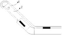
- FIG. 1which is a positional relationship diagram of the inlet pipe 1 and the cutter head fixing portion 2 in the conventional structure
- the inlet pipe 1is fixed to the outside of the cutter head fixing portion 2, and the inlet pipe 1 is assembled and fixed.
- the tip of the medical waterjet instrumenthas a large size, which increases the incision of the surgical site during the operation, increases the wound surface, and is not conducive to the rehabilitation of the surgical site;
- the tube 1is located outside the cutter head fixing portion 2, which is disadvantageous for the recovery of the waste liquid jet during the operation.
- the present inventionprovides a medical cutter head structure, a medical waterjet instrument and a molding method thereof.
- a medical cutter head structure disclosed in the first aspect of the inventioncomprising:
- a curved headprovided at the end of the body portion
- the end of the first positioning grooveextends in the bending direction of the curved head, and the second positioning groove is formed in the curved head.
- the width of the body portionis defined as a width D1 along the width direction of the first positioning groove; and the longitudinal section of the bending head defines a width along the width direction of the second positioning groove. Is D2; D1 is not less than D2.
- the outer side surfaces of the two groove walls of the first positioning groove and the outer side surfaces of the second positioning groove wallare curved surfaces.
- the outer sides of the two groove walls of the first positioning grooveare both inclined faces;
- the outer sides of the two groove walls whose position grooves are parallel to the groove lengthare inclined surfaces.
- the first positioning grooveis equally spaced from the outer side surface of the two groove walls.
- the distance between the first positioning groove and the outer side surface of the two groove wallsis gradually reduced along the top end of the body portion to the end direction.
- the distance between the first positioning groove and the outer side surface of the two groove wallsis gradually reduced along the top end of the body portion to the end direction.
- the methodfurther includes:
- first positioning rib and a second positioning ribdisposed opposite to each other in a direction of a length of the first positioning groove
- the first positioning rib and the second positioning ribare respectively connected to the two side walls of the first positioning groove;
- the wall thicknesses of the first positioning rib and the second positioning ribare smaller than the thickness of the first positioning groove wall, and the outer sides of the two are respectively spaced apart from the outer mask of the groove wall connected thereto.
- the body portion, the curved head portion, the first positioning rib and the second positioning ribare integrally formed.
- a method for forming a medical cutter head structure disclosed in the second aspect of the inventionwhich adopts a machining forming process to mold the medical cutter head structure according to the first aspect of the invention.
- a method for forming a medical cutter head structure disclosed in the third aspect of the inventionwhich uses the powder metallurgy molding process to form the medical cutter head structure according to the first aspect of the invention.
- a method for forming a medical cutter head structure disclosed in the fourth aspect of the inventionwhich uses the metal injection molding process to mold the medical cutter head structure according to the first aspect of the invention.
- a medical waterjet device disclosed in the fifth aspect of the inventioncomprising:
- the medical cutter head structurethe connecting pipe, the filter, and the first aspect of the present invention
- the inlet pipeincludes: a connected elbow portion and a straight pipe portion, the elbow portion has a head, and the head is provided with a spray hole;
- the top end of the body portionis connected to the jet recovery port
- a part of the pipe body near the curved pipe portion of the straight pipe portionis positioned in the first positioning groove, and the pipe portion of the middle portion is nested back In the liquid pipe, the tail end is connected to the filter through the connecting pipe;
- the curved pipe portionis positioned in the second positioning groove, and the injection hole is opposite to the jet recovery port;
- the inlet pipeprovides a passage for the liquid to flow to the orifice; the orifice causes the liquid flowing therethrough to form a liquid jet, and the jet recovery port receives the jet of liquid ejected by the orifice.
- the filtercomprises:
- Liquid inlet portion, filter screen plate and liquid discharge portionLiquid inlet portion, filter screen plate and liquid discharge portion
- the liquid inlet portion and the liquid outlet portionare each provided with a through hole in the axial direction, and the straight tube portion communicates with the through hole in the liquid outlet portion;
- the filter screenis disposed between the liquid inlet portion and the liquid outlet portion.
- a method for forming a medical waterjet instrument disclosed in the sixth aspect of the inventioncomprising:
- the liquid inlet pipeis bent, and the liquid inlet pipe comprises: a connecting elbow portion and a straight pipe portion, the elbow portion has a head, and the head is provided with a spray hole;
- the liquid return pipehas a jet recovery port
- the connecting pipeis connected to the end of the liquid return pipe, and the tail end of the straight pipe portion passes through the connecting pipe;
- the medical cutter head structureis assembled, the top end of the body portion is connected to the jet recovery port, and a part of the pipe body near the curved pipe portion of the straight pipe portion is positioned in the first positioning groove, the curved pipe portion is positioned in the second positioning groove, and the jet opposite flow is recovered. mouth;
- the medical tip structure of the first aspect of the inventionis formed by a machining forming process.
- the medical tip structure of the first aspect of the inventionis formed by a powder metallurgy molding process.
- the medical tip structure of the first aspect of the inventionis formed using a metal injection molding process.
- the methodfurther includes: forming a filter, forming a through hole in an axial direction of the liquid inlet portion and the liquid outlet portion, and providing a filter mesh plate between the liquid inlet portion and the liquid outlet portion, and fixedly connecting the liquid inlet Department and fluid
- the tail end of the straight pipe portionpasses through the connecting pipe to connect the liquid discharging portion and communicates with the through hole of the liquid discharging portion.
- the two end faces of the liquid inlet portion and the liquid discharge portionare fixedly connected by welding.
- the tail end of the straight pipe portionis connected to the liquid discharge portion by laser spot welding.
- laser spot weldingis performed between the curved pipe portion and the second positioning groove, and the curved pipe portion is positioned in the second positioning groove.
- laser spot weldingis performed between a portion of the straight tube portion adjacent to the curved portion and the first positioning groove, and a portion of the straight tube portion adjacent to the curved portion is positioned at the first positioning. In the slot.
- laser weldingis performed on at least one outer side of the body portion and the inner wall of the liquid return pipe, and the tip end of the body portion is connected to the jet recovery port.
- the liquid inlet tubeis disposed inside the medical cutter head structure.
- the size of the medical cutter headis required to be constant, the top end of the medical waterjet instrument is significantly smaller than the medical water in the existing structure.
- the size of the tip of the knife device, the medical waterjet deviceis miniaturized, thereby reducing the surgical incision of the patient during the operation and reducing the wound area; and further, since the width of the first positioning groove width is not less than the second positioning groove.
- the width of the width directionwhen the top end of the medical waterjet instrument extends into the patient's surgical site during the operation, the incision of the surgical site does not change or gradually increases with the depth of the waterjet instrument, which is more conducive to the postoperative wound surface of the patient. Rehabilitation.
- FIG. 1is a view showing a positional relationship between a liquid inlet tube and a medical cutter head structure in the prior art
- FIG. 2is a schematic structural view of a medical cutter head structure in the first embodiment
- FIG. 3is a schematic view showing another structure of the medical cutter head structure in the first embodiment
- Figure 4is a plan view showing the structure of the medical cutter head in the first embodiment
- Figure 5is a schematic structural view of a medical cutter head structure in the second embodiment
- FIG. 6is another schematic structural view of a medical cutter head structure in the second embodiment
- Figure 7is a plan view showing the structure of the medical cutter head in the second embodiment
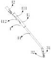
- FIG. 8is a schematic structural view of a medical waterjet instrument in the third embodiment
- Figure 9is a schematic view showing another structure of the medical waterjet instrument of the third embodiment.
- Figure 10is a schematic view showing still another structure of the medical waterjet instrument in the third embodiment.
- Figure 11is a schematic exploded view of the medical waterjet device of the third embodiment.
- FIG. 12is a schematic structural view of a medical waterjet instrument in the third embodiment
- Figure 13is a schematic view showing another structure of the medical waterjet instrument of the third embodiment.
- Figure 14is a schematic view showing still another structure of the medical waterjet instrument in the third embodiment.
- Figure 15is a schematic exploded view of the medical waterjet instrument of the third embodiment.
- first”, “second” and the like in the present inventionare used for the purpose of description only, and are not intended to specifically refer to the order or the order, and are not intended to limit the present invention.
- the same technical termsare used to describe the components or operations, and are not to be construed as indicating or implying their relative importance or implicitly indicating the number of technical features indicated.
- features defining “first” or “second”may include at least one of the features, either explicitly or implicitly.
- the technical solutions between the various embodimentsmay be combined with each other, but must be based on the realization of those skilled in the art, and when the combination of the technical solutions is contradictory or impossible to implement, it should be considered that the combination of the technical solutions does not exist. It is also within the scope of protection required by the present invention.
- the inventionrelates to a related design of a medical cutter head structure, a medical waterjet instrument and a molding method thereof.
- the medical cutter head structure of the present inventionis very suitable for use in various surgical minimally invasive surgerys for positioning a liquid inlet tube, facilitating the introduction of a high-pressure liquid into the liquid inlet tube, and cutting and ablating various tissues or organs of the patient's body.
- the medical tip structure of the present inventionis also applicable to other instruments to be cut or perforated for positioning other liquid inlet members similar to the inlet tube; of course, the present invention
- the medical cutter head structurecan also be applied to other liquid ejection devices having various structures and various purposes to position other liquid inlet members.
- the medical waterjet instrumentis used in various surgical minimally invasive surgery, and can also be used for other objects to be cut or perforated.
- the medical cutter head structure of the present inventionis positioned for other liquid inlet members for use in other liquid ejecting devices having various structures and various purposes, the liquid introduced into the liquid inlet member can be appropriately selected according to the purpose of use thereof. Whether it is a high pressure liquid or a normal liquid.
- the embodiment of the medical waterjet instrument provided by the present inventioncan be combined with externally held grips of various configurations, so that the operator can comfortably hold the hand by hand, so that the medical waterjet instrument can be more conveniently used for various purposes.
- the medical cutter head structure, the medical waterjet instrument and the molding method thereof of the present inventionare further described in detail, and the benefits thereof are provided.
- the medical waterjet deviceis mainly used for positioning the medical tube in the medical blade structure, and the medical waterjet device is used in various surgical minimally invasive surgery as an example.
- a high-pressure liquidis introduced into the inlet pipe, but this does not constitute a limitation of the present invention.
- the manner in which the medical cutter head is positioned to the liquid inlet tube and the position of the medical cutter head to position the other liquid inlet member to form the water jet tool and the benefitsare basically the same as when the high pressure liquid is introduced, but the purpose of use is different.
- the high-pressure liquidincludes a high-pressure water flow or a high-pressure physiological saline flow or other high-pressure liquid flow
- the type of the high-pressure liquid in the inlet pipedepends on the type or physical and chemical properties of the object to be cut when the medical waterjet device operates. Flexible selection.
- Embodiment 1is a diagrammatic representation of Embodiment 1:
- the medical cutter head structure 3includes a body portion 31 and a curved head portion 32.
- the end of the body portion 31extends toward a direction opposite to itself to form a curved head portion 32, where the angle is greater than zero degrees and less than one hundred and eighty. Any angle between degrees, preferably ninety degrees, has a curved curvature.
- One of the surfaces of the main body portion 31is recessed inwardly to form a first positioning groove 33.
- the first positioning groove 33extends longitudinally, and the longitudinal direction refers to a direction parallel to the direction in which the groove length of the first positioning groove 33 is long.
- the first positioning groove 33has opposite two groove walls and a bottom wall.
- the end of the first positioning groove 33extends along the bending direction of the bending head 32, and the second positioning groove 34 is formed in the bending head 32.
- the second positioning groove 34has two opposite groove walls, a bottom wall and two ends and two Another groove wall to which the groove walls are respectively connected. Further, in the cross section of the body portion 31, the width in the groove width direction of the first positioning groove 33 is defined as D1; in the longitudinal section of the curved head portion 32, it is defined along the groove width direction of the second positioning groove 34.
- the widthis D2; D1 is not less than D2, and the transverse cross section of the main body portion 31 refers to a cross-sectional shape obtained by cutting the main body portion 31 perpendicularly to the extending direction of the groove length of the first positioning groove 33; the longitudinal section of the curved head portion 32, It refers to a cross-sectional shape obtained by cutting the curved head portion 32 along a direction parallel to the groove length of the first positioning groove 33.
- the outer side surfaces of the wall and the groove wall of the second positioning groove 34are all curved surfaces, and the curved outer side surfaces of the two groove walls of the first positioning groove 33 are outwardly protruded away from the inner side surface of the groove wall of the first positioning groove 33, The curved outer side surface of the slot wall of the two positioning slots 34 protrudes away from the inner side surface of the slot wall of the second positioning slot 34.
- the distance between the first positioning groove 33 and the outer side surface of the two groove wallsis gradually decreased along the top end of the main body portion 31, and the two groove walls of the first positioning groove 33 and the groove wall of the second positioning groove 34 are gradually decreased.
- the outer side surfacesare all curved surfaces, the longitudinal section of the body portion 31 is trapezoidal, and D1 is larger than D2.
- the medical cutter head structure 3further includes: a first positioning rib 35 and a second positioning rib 36 disposed opposite to each other in the direction of the slot length of the first positioning slot 33; the first positioning rib 35 and the second positioning rib 36 is respectively connected to the two side walls of the first positioning groove 33; wherein the wall thickness of the first positioning rib 35 and the second positioning rib 36 are smaller than the thickness of the groove wall of the first positioning groove 33, and the outer sides of the two are respectively
- the outer mask of the connected groove wallhas a spacing, preferably greater than or equal to the thickness of the wall of the liquid return tube in the medical waterjet instrument, more preferably equal to the thickness of the wall of the liquid return tube in the medical waterjet instrument.
- the first positioning rib 35 and the second positioning rib 36are used to position the body portion 31 in a liquid return pipe to be described later.
- the main body portion 31, the curved head portion 32, the first positioning rib 35, and the second positioning rib 36are integrally formed.
- the medical cutter head structure 3can be formed by a machining molding process, a powder metallurgy molding process, or a metal injection molding process.
- the liquid inlet tube 1is disposed inside the medical cutter head structure 3.
- the tip size of the medical waterjet knife device 4is significantly smaller than that of the existing structure.
- the size of the top end of the water knife device 4, the medical water jet deviceis miniaturized, thereby reducing the wound area of the patient during the operation; and, because the width of the first positioning groove 33 in the groove width direction is not less than the groove width direction of the second positioning groove 34 Width, when the top end of the medical waterjet instrument 4 continuously extends into the inside of the patient's surgical site during the operation, the lateral trauma area of the surgical site will not change or gradually increase with the increase of the depth of penetration, which is more conducive to the rehabilitation of the wound surface after operation.
- the groove wall of the first positioning groove and the groove wall of the second positioning grooveare formed into a curved surface or a sloped surface to facilitate cutting of the surgical blade.
- Embodiment 2is a diagrammatic representation of Embodiment 1:
- this exampleprovides a medical tip structure 3 of another configuration.
- the outer side surfaces of the two groove walls of the first positioning groove 33are all inclined surfaces; the outer side surfaces of the two groove walls parallel to the direction of the groove length of the second positioning groove 34 are all inclined surfaces.
- One of the groove walls of the first positioning groove 33 and one of the groove walls of the second positioning groove 34are located on the same side of the longitudinal section of the medical cutter head structure 3, and the outer sides of the second positioning groove 34 are inclined.
- FIG. 5-7please refer to FIG. 5-7.
- the body portion 31has a trapezoidal longitudinal section and D1 is larger than D2.
- Embodiment 3is a diagrammatic representation of Embodiment 3
- This exampleprovides a medical waterjet instrument 4, with reference to Figures 8-15, wherein the medical blade structure 3 shown in Figures 8-11 is the same as the first embodiment; Figure 12-15 In the medical waterjet instrument 4 shown, the medical cutter head structure 3 is the same as that of the second embodiment.
- the medical waterjet instrument 4includes a medical cutter head structure 3, a connecting tube 41, a filter 42, a liquid inlet tube 1, and a liquid return tube 44.
- the inlet pipe 1includes a communicating elbow portion 432 and a straight tube portion 431.
- the elbow portion 432has a head 4321, and the head 4321 is provided with an injection hole 4322. See the enlarged view of the elbow portion A in FIG.
- the straight pipe portion 431has an integrally formed four-segment straight pipe, or a tubular body is bent to form a straight pipe portion 431 having a four-segment straight pipe. As shown in FIG.
- one end of the first sub-straight pipe 431ais connected to the curved pipe portion 432, and the other One end is connected to the second sub-straight tube 431b, the other end of the second sub-straight tube 431b is connected to the third sub-straight tube 431c, and the other end of the third sub-straight tube 431c is connected to the fourth sub-straight tube 431d, and the first sub-straight tube 431a is
- the second sub-straight tube 431bhas an included angle
- the second sub-straight tube 431bhas an angle with the third sub-straight tube 431c
- the third sub-straight tube 431chas an angle with the fourth sub-straight tube 431d
- the four sub-segmentsare straight.
- the tubeseach have a tube wall and a tube lumen.
- the head 4321is a convex head such as a circular arc face seal or a conical head, which can smooth the high pressure liquid flowing into the bend portion 432. Transition to the orifice 4322.
- the inlet pipe 1is for providing a flow path of the high-pressure liquid to the injection hole 4322, and the inlet pipe 1 can be made of various materials, no matter what material is selected to be the inlet pipe 1, and the method is formed in any of the above manners.
- the pressure of the high pressure liquid used to form the liquid jet during operation of the medical waterjet instrument 4depends on the design of the orifice 4322 and the hardness or strength of the tissue or object to be cut, ablated or eliminated.
- the inlet tube 1can be a circular tube, an elliptical tube, a square tube or other shaped tube.
- the liquid return tube 44has a jet recovery port 441 for recovering a liquid jet ejected from the orifice 4322 in a minimally invasive procedure.
- the shape of the liquid return pipe 44matches the shape of the first sub-straight tube 431a and the second sub-straight tube 431b.
- the connecting pipe 41has a main pipe 411, and a branch body 412 communicating with the main pipe 411 is provided on the side wall of the main pipe 411.
- the filter 42can be designed in the prior art, or the filter 42 includes a liquid inlet portion 421, a filter mesh plate 422, and a liquid outlet portion 423.
- the liquid inlet portion 421 and the liquid outlet portion 423are each provided with a through hole in the axial direction.
- the straight pipe portion 431communicates with the through hole in the liquid discharge portion 423; the filter mesh plate 422 is provided between the liquid inlet portion 421 and the liquid discharge portion 423.
- the top end of the main body portion 31 of the medical cutter head structure 3is connected to the jet flow recovery port 441; the curved pipe portion 432 of the liquid inlet pipe 1 is positioned in the second positioning groove 34, the injection hole 4322 is opposed to the jet flow recovery port 441, and the straight pipe portion 431 is close to
- the portion of the tube portion 432, that is, the first sub-straight tube 431ais positioned in the first positioning groove 33, the intermediate portion of the tube, that is, the second sub-tube 431b, is inserted into the liquid return tube 44, and the tail end is passed through the connecting tube 41.
- the third sub-straight tube 431cis partially disposed in the branch body 412, and the fourth sub-straight tube 431d is connected to the filter 42; the end of the liquid return tube 44 is sleeved in the connecting tube 41.
- the liquid inlet portion 421 of the filter 42communicates with an external high-pressure liquid supply source such as a high-pressure pump, and the through-hole on the liquid inlet portion 421 passes through a high-pressure liquid delivery passage such as a pressure tube and a high-pressure pump fluid.
- a high-pressure liquid delivery passagesuch as a pressure tube and a high-pressure pump fluid.
- the inner tube of the third sub-straight tube 431c, the second sub-straight tube 431b, the first sub-straight tube 431a, and the elbow portion 432continuously flows toward the injection hole 4322, and various liquid jets of different shapes are formed through the injection hole 4322.
- the high pressure generated by the jet of liquid sprayed by the spray hole 4322can cause the medical water jet instrument 4 to perform various surgical minimally invasive surgery or cutting and punching of various other objects, etc., and those skilled in the art can understand that when When the medical waterjet instrument 4 is used in various surgical minimally invasive surgery, many types of high pressure pumps can be applied to this embodiment, including but not limited to a piston pump and a diaphragm pump; the orifice 4322 has a suitable shape, such as a circle.
- a cross-section, an elliptical cross-section or a rectangular cross-section or other cross-sectional shapeenables a high-pressure liquid to flow through the orifice 4322 to form a liquid jet of a different shape suitable for a particular need, and the liquid jet can be used in surgical minimally invasive surgery. Cut, ablate, or remove peel each patient's body tissues or organs, or to perform other cutting objects to be cutting or drilling action.
- the size of the orifice 4322is designed according to the amount of liquid jet required for the operation.
- the liquid jet ejected from the injection hole 4322flows into the liquid return pipe 44 from the jet recovery port 441, flows through the liquid return pipe 44 to the main pipe 411 of the connection pipe 41, and the main pipe 411 can be connected to the external liquid recovery device to spray the injection hole 4322.
- the liquid jetis recovered.
- Embodiment 4is a diagrammatic representation of Embodiment 4:
- This embodimentprovides a molding process of the medical waterjet instrument 4 according to the third embodiment.
- the liquid inlet pipe 1includes a communicating elbow portion 432 and a straight pipe portion 431.
- the elbow portion 432has a sealing head 4321, and the sealing head 4321 is provided with an injection hole 4322. Specifically, a suitable one is selected. a standard pipe body, the pipe body is bent to form a straight pipe portion 431 having a four-segment straight pipe and a curved pipe portion 432;
- the liquid return pipe 44is bent, and the liquid return pipe 44 has a jet recovery port 441; the shape of the liquid return pipe 44 matches the shape of the first sub straight pipe 431a and the second sub straight pipe 431b.
- the connecting pipe 41is at the end of the liquid return pipe 44, and the tail end of the straight pipe portion 431 passes through the connecting pipe 41;
- the medical head structure 3is assembled, the top end of the main body portion 31 is connected to the jet recovery port 441, and a portion of the straight tube portion 431 adjacent to the curved tube portion 432 is positioned in the first positioning groove 33, and the curved portion 432 is positioned in the second positioning groove. 34, the injection hole 4322 opposite the jet recovery port 441;
- the filter 42is connected to the end of the straight tube portion 431.
- the molded medical cutter head structure 3the molded connecting pipe 41, the bent liquid inlet pipe 1, and the bent liquid return pipe 44 are in no particular order.
- the medical cutter head structure 3is formed by any one of a machining molding, a powder metallurgy molding process, and a metal injection molding process.
- the filter 42may have a conventional design, and may also adopt a molding process in which a through hole is formed in the axial direction of the liquid inlet portion 421 and the liquid outlet portion 423, and a filter mesh plate 422 is disposed between the liquid inlet portion 421 and the liquid outlet portion 423.
- the liquid inlet portion 421 and the liquid discharge portion 423are fixedly connected, and the tail end of the straight tube portion 431 passes through the connection pipe 41 to connect the liquid discharge portion 423 and communicates with the through hole 424 of the liquid inlet portion.
- the two end faces of the liquid inlet portion 421 and the liquid discharge portion 423are fixedly connected by welding.
- the tail end of the straight pipe portion 431is connected to the liquid discharge portion 423, and the liquid discharge portion 423 is preferably connected by laser spot welding.
- the fourth straight pipe 431dcan be first inserted into the end of the liquid return pipe 44.
- the bent pipe portion 432is positioned in the second positioning groove. 34.
- a portion of the tubular portion of the straight tube portion 431 that is adjacent to the curved portion 432is positioned in the first positioning groove 33.
- the elbow portion 432is positioned in the second positioning groove 34 by laser spot welding between the curved portion 432 and the second positioning groove 34.
- a portion of the tube of the straight tube portion 431 adjacent to the curved portion 432is positioned in the first positioning groove 33 by laser spot welding between a portion of the tube portion 431 of the straight tube portion 431 adjacent to the curved portion 432 and the first positioning groove 33.
- Laserly spot weldingat least one outer side of the main body portion 31 and the inner wall of the liquid return pipe 44, and connecting the top end of the main body portion 31 to the jet recovery port 441; preferably, the first positioning rib 35 disposed on the two groove walls of the first positioning groove 33 or
- the second positioning rib 36 and the liquid return pipe 44are laser-welded, and the top end of the main body portion 31 is connected to the jet recovery port 441.
- the thickness of the pipe wall of the liquid return pipe 44is equal to the outer side surface of the first positioning rib 35 and the groove connected thereto. The spacing between the outer sides of the walls.
Landscapes
- Health & Medical Sciences (AREA)
- Engineering & Computer Science (AREA)
- Life Sciences & Earth Sciences (AREA)
- Surgery (AREA)
- General Engineering & Computer Science (AREA)
- Medical Informatics (AREA)
- Nuclear Medicine, Radiotherapy & Molecular Imaging (AREA)
- Mechanical Engineering (AREA)
- Fluid Mechanics (AREA)
- Biomedical Technology (AREA)
- Heart & Thoracic Surgery (AREA)
- Physics & Mathematics (AREA)
- Molecular Biology (AREA)
- Animal Behavior & Ethology (AREA)
- General Health & Medical Sciences (AREA)
- Public Health (AREA)
- Veterinary Medicine (AREA)
- Surgical Instruments (AREA)
Abstract
Description
Translated fromChinese本发明涉及用于产生液体射流的器械以及所述器械的成型方法,具体的,涉及一种医用刀头结构、医用水刀器械及其成型方法。The present invention relates to an apparatus for producing a liquid jet and a method of forming the same, and more particularly to a medical cutter head structure, a medical water jet apparatus, and a molding method thereof.
如图1所示,为现有结构中进液管1与刀头固定部2的定位位置关系图,进液管1固定于刀头固定部2的外侧,当装配固定有进液管1的刀头固定部2,形成医用水刀器械时,医用水刀器械顶端尺寸偏大,增大手术过程中手术部位的切口,增大创伤面,不利于手术部位的康复;另一方面,进液管1位于刀头固定部2的外侧,不利于手术过程中废弃液体射流的回收。As shown in FIG. 1 , which is a positional relationship diagram of the inlet pipe 1 and the cutter head fixing portion 2 in the conventional structure, the inlet pipe 1 is fixed to the outside of the cutter head fixing portion 2, and the inlet pipe 1 is assembled and fixed. When the blade head fixing portion 2 forms a medical waterjet instrument, the tip of the medical waterjet instrument has a large size, which increases the incision of the surgical site during the operation, increases the wound surface, and is not conducive to the rehabilitation of the surgical site; The tube 1 is located outside the cutter head fixing portion 2, which is disadvantageous for the recovery of the waste liquid jet during the operation.
发明内容Summary of the invention
针对现有技术的不足,本发明提供一种医用刀头结构、医用水刀器械及其成型方法。In view of the deficiencies of the prior art, the present invention provides a medical cutter head structure, a medical waterjet instrument and a molding method thereof.
本文第一方面公开的一种医用刀头结构,其包括:A medical cutter head structure disclosed in the first aspect of the invention, comprising:
本体部,其表面内凹形成纵向延伸的第一定位槽,以及a body portion whose surface is concavely formed to form a longitudinally extending first positioning groove, and
设于本体部末端的弯头部;a curved head provided at the end of the body portion;
第一定位槽的末端沿弯头部的弯曲方向延伸,于弯头部形成第二定位槽。The end of the first positioning groove extends in the bending direction of the curved head, and the second positioning groove is formed in the curved head.
根据本发明的一实施方式,本体部的横剖面中,定义其沿第一定位槽槽宽方向的宽度为D1;弯头部的纵剖面中,定义其沿第二定位槽槽宽方向的宽度为D2;D1不小于D2。According to an embodiment of the present invention, the width of the body portion is defined as a width D1 along the width direction of the first positioning groove; and the longitudinal section of the bending head defines a width along the width direction of the second positioning groove. Is D2; D1 is not less than D2.
根据本发明的一实施方式,第一定位槽两槽壁的外侧面及第二定位槽槽壁的外侧面均为弧形面。According to an embodiment of the invention, the outer side surfaces of the two groove walls of the first positioning groove and the outer side surfaces of the second positioning groove wall are curved surfaces.
根据本发明的一实施方式,第一定位槽两槽壁的外侧面均为斜面;第二定位槽平行其槽长所在方向的两槽壁的外侧面均为斜面。According to an embodiment of the present invention, the outer sides of the two groove walls of the first positioning groove are both inclined faces;The outer sides of the two groove walls whose position grooves are parallel to the groove length are inclined surfaces.
根据本发明的一实施方式,第一定位槽相对两槽壁的外侧面之间间距相等。According to an embodiment of the invention, the first positioning groove is equally spaced from the outer side surface of the two groove walls.
根据本发明的一实施方式,沿本体部的顶端延伸至末端方向,第一定位槽相对两槽壁的外侧面之间间距逐渐减小。According to an embodiment of the invention, the distance between the first positioning groove and the outer side surface of the two groove walls is gradually reduced along the top end of the body portion to the end direction.
根据本发明的一实施方式,沿本体部的顶端延伸至末端方向,第一定位槽相对两槽壁的外侧面之间间距逐渐减小。According to an embodiment of the invention, the distance between the first positioning groove and the outer side surface of the two groove walls is gradually reduced along the top end of the body portion to the end direction.
根据本发明的一实施方式,其还包括:According to an embodiment of the present invention, the method further includes:
沿第一定位槽槽长所在方向相对设置的第一定位筋及第二定位筋;a first positioning rib and a second positioning rib disposed opposite to each other in a direction of a length of the first positioning groove;
第一定位筋及第二定位筋分别连接于第一定位槽的两侧壁;The first positioning rib and the second positioning rib are respectively connected to the two side walls of the first positioning groove;
其中,第一定位筋及第二定位筋的壁厚均小于第一定位槽槽壁的厚度,二者的外侧面分别与与之连接的槽壁的外侧面具有一间距。Wherein, the wall thicknesses of the first positioning rib and the second positioning rib are smaller than the thickness of the first positioning groove wall, and the outer sides of the two are respectively spaced apart from the outer mask of the groove wall connected thereto.
根据本发明的一实施方式,本体部、弯头部及第一定位筋、第二定位筋一体成型。According to an embodiment of the invention, the body portion, the curved head portion, the first positioning rib and the second positioning rib are integrally formed.
本文第二方面公开的一种医用刀头结构的成型方法,采用机加工成型工艺,成型本发明第一方面所述的医用刀头结构。A method for forming a medical cutter head structure disclosed in the second aspect of the invention, which adopts a machining forming process to mold the medical cutter head structure according to the first aspect of the invention.
本文第三方面公开的一种医用刀头结构的成型方法,采用粉末冶金成型工艺,成型本发明第一方面所述的医用刀头结构。A method for forming a medical cutter head structure disclosed in the third aspect of the invention, which uses the powder metallurgy molding process to form the medical cutter head structure according to the first aspect of the invention.
本文第四方面公开的一种医用刀头结构的成型方法,采用金属注射成型工艺,成型本发明第一方面所述的医用刀头结构。A method for forming a medical cutter head structure disclosed in the fourth aspect of the invention, which uses the metal injection molding process to mold the medical cutter head structure according to the first aspect of the invention.
本文第五方面公开的一种医用水刀器械,其包括:A medical waterjet device disclosed in the fifth aspect of the invention, comprising:
本发明第一方面所述的医用刀头结构、连接管、过滤器,以及The medical cutter head structure, the connecting pipe, the filter, and the first aspect of the present invention
进液管,其包括:连通的弯管部及直管部,弯管部具有封头,封头上设有喷孔;以及The inlet pipe includes: a connected elbow portion and a straight pipe portion, the elbow portion has a head, and the head is provided with a spray hole;
回液管,其具有射流回收口,末端套接于连接管内;a liquid return pipe having a jet recovery port, the end being sleeved in the connecting pipe;
本体部顶端接于射流回收口;The top end of the body portion is connected to the jet recovery port;
直管部中靠近弯管部的部分管体定位于第一定位槽,中间部分管体套入回液管内,尾端穿出连接管与过滤器相连;A part of the pipe body near the curved pipe portion of the straight pipe portion is positioned in the first positioning groove, and the pipe portion of the middle portion is nested backIn the liquid pipe, the tail end is connected to the filter through the connecting pipe;
弯管部定位于第二定位槽,喷孔对置射流回收口;The curved pipe portion is positioned in the second positioning groove, and the injection hole is opposite to the jet recovery port;
其中,进液管提供液体流向喷孔的通路;喷孔使流过其的液体形成液体射流喷出,射流回收口接收喷孔喷出的液体射流。Wherein, the inlet pipe provides a passage for the liquid to flow to the orifice; the orifice causes the liquid flowing therethrough to form a liquid jet, and the jet recovery port receives the jet of liquid ejected by the orifice.
根据本发明的一实施方式,过滤器包括:According to an embodiment of the invention, the filter comprises:
进液部、过滤网板及出液部;Liquid inlet portion, filter screen plate and liquid discharge portion;
进液部及出液部沿轴向均设有一通孔,直管部与出液部中的通孔连通;The liquid inlet portion and the liquid outlet portion are each provided with a through hole in the axial direction, and the straight tube portion communicates with the through hole in the liquid outlet portion;
过滤网板设于进液部及出液部之间。The filter screen is disposed between the liquid inlet portion and the liquid outlet portion.
本文第六方面公开的一种医用水刀器械成型方法,其包括:A method for forming a medical waterjet instrument disclosed in the sixth aspect of the invention, comprising:
分别成型本发明第一方面所述的医用刀头结构及连接管;Forming the medical cutter head structure and the connecting pipe according to the first aspect of the invention;
弯折进液管,进液管包括:连通的弯管部及直管部,弯管部具有封头,封头上设有喷孔;The liquid inlet pipe is bent, and the liquid inlet pipe comprises: a connecting elbow portion and a straight pipe portion, the elbow portion has a head, and the head is provided with a spray hole;
弯折回液管,回液管具有射流回收口;Bending the liquid return pipe, the liquid return pipe has a jet recovery port;
插入进液管于回液管,直管部的中间部分管体套入回液管内;Inserting the liquid inlet pipe into the liquid return pipe, and inserting the pipe body in the middle portion of the straight pipe portion into the liquid return pipe;
接入连接管于回液管末端,直管部尾端穿出连接管;The connecting pipe is connected to the end of the liquid return pipe, and the tail end of the straight pipe portion passes through the connecting pipe;
装配医用刀头结构,本体部顶端接于射流回收口,直管部中靠近弯管部的部分管体定位于第一定位槽,弯管部定位于第二定位槽,喷孔对置射流回收口;The medical cutter head structure is assembled, the top end of the body portion is connected to the jet recovery port, and a part of the pipe body near the curved pipe portion of the straight pipe portion is positioned in the first positioning groove, the curved pipe portion is positioned in the second positioning groove, and the jet opposite flow is recovered. mouth;
连接过滤器于直管部尾端。Connect the filter to the end of the straight tube.
根据本发明的一实施方式,采用机加工成型工艺,成型本发明第一方面所述的医用刀头结构。According to an embodiment of the present invention, the medical tip structure of the first aspect of the invention is formed by a machining forming process.
根据本发明的一实施方式,采用粉末冶金成型工艺,成型本发明第一方面所述的医用刀头结构。According to an embodiment of the present invention, the medical tip structure of the first aspect of the invention is formed by a powder metallurgy molding process.
根据本发明的一实施方式,采用金属注射成型工艺,成型本发明第一方面所述的医用刀头结构。According to an embodiment of the invention, the medical tip structure of the first aspect of the invention is formed using a metal injection molding process.
根据本发明的一实施方式,其还包括:成型过滤器,于进液部及出液部的轴向形成通孔,设置过滤网板于进液部及出液部之间,固定连接进液部及出液部,直管部的尾端穿出连接管连接出液部,并连通出液部的通孔。According to an embodiment of the present invention, the method further includes: forming a filter, forming a through hole in an axial direction of the liquid inlet portion and the liquid outlet portion, and providing a filter mesh plate between the liquid inlet portion and the liquid outlet portion, and fixedly connecting the liquid inlet Department and fluidThe tail end of the straight pipe portion passes through the connecting pipe to connect the liquid discharging portion and communicates with the through hole of the liquid discharging portion.
根据本发明的一实施方式,进液部及出液部正对的两个端面通过焊接固定连接。According to an embodiment of the present invention, the two end faces of the liquid inlet portion and the liquid discharge portion are fixedly connected by welding.
根据本发明的一实施方式,直管部的尾端通过激光点焊连接出液部。According to an embodiment of the invention, the tail end of the straight pipe portion is connected to the liquid discharge portion by laser spot welding.
根据本发明的一实施方式,于弯管部与第二定位槽之间激光点焊,将弯管部定位于第二定位槽中。According to an embodiment of the invention, laser spot welding is performed between the curved pipe portion and the second positioning groove, and the curved pipe portion is positioned in the second positioning groove.
根据本发明的一实施方式,于直管部中靠近弯管部的部分管体与第一定位槽之间激光点焊,将直管部中靠近弯管部的部分管体定位于第一定位槽中。According to an embodiment of the present invention, laser spot welding is performed between a portion of the straight tube portion adjacent to the curved portion and the first positioning groove, and a portion of the straight tube portion adjacent to the curved portion is positioned at the first positioning. In the slot.
根据本发明的一实施方式,于本体部至少一外侧与回液管内壁激光点焊,将本体部顶端接于射流回收口。According to an embodiment of the present invention, laser welding is performed on at least one outer side of the body portion and the inner wall of the liquid return pipe, and the tip end of the body portion is connected to the jet recovery port.
本发明的医用刀头结构用于定位进液管时,进液管设于医用刀头结构的内部,当要求医用刀头结构尺寸一定时,医用水刀器械顶端尺寸明显小于现有结构中医用水刀器械顶端的尺寸,医用水刀器械微型化,从而减小手术过程中患者手术切口,减小创伤面积;并且,进一步地,由于第一定位槽槽宽方向的宽度不小于第二定位槽槽宽方向的宽度,当手术过程中医用水刀器械顶端伸入患者手术部位内部时,手术部位切口随着水刀器械伸入深度的增大不变或逐渐增大,更有利于患者术后创伤面的康复。When the medical cutter head structure of the present invention is used for positioning the liquid inlet tube, the liquid inlet tube is disposed inside the medical cutter head structure. When the size of the medical cutter head is required to be constant, the top end of the medical waterjet instrument is significantly smaller than the medical water in the existing structure. The size of the tip of the knife device, the medical waterjet device is miniaturized, thereby reducing the surgical incision of the patient during the operation and reducing the wound area; and further, since the width of the first positioning groove width is not less than the second positioning groove The width of the width direction, when the top end of the medical waterjet instrument extends into the patient's surgical site during the operation, the incision of the surgical site does not change or gradually increases with the depth of the waterjet instrument, which is more conducive to the postoperative wound surface of the patient. Rehabilitation.
此处所说明的附图用来提供对本申请的进一步理解,构成本申请的一部分,本申请的示意性实施例及其说明用于解释本申请,并不构成对本申请的不当限定。在附图中:The drawings described herein are intended to provide a further understanding of the present application, and are intended to be a part of this application. In the drawing:
图1为现有技术中进液管与医用刀头结构的定位位置关系图;1 is a view showing a positional relationship between a liquid inlet tube and a medical cutter head structure in the prior art;
图2为实施例一中医用刀头结构的一结构示意图;2 is a schematic structural view of a medical cutter head structure in the first embodiment;
图3为实施例一中医用刀头结构的另一结构示意图;3 is a schematic view showing another structure of the medical cutter head structure in the first embodiment;
图4为实施例一中医用刀头结构的俯视图;Figure 4 is a plan view showing the structure of the medical cutter head in the first embodiment;
图5为实施例二中医用刀头结构的一结构示意图;Figure 5 is a schematic structural view of a medical cutter head structure in the second embodiment;
图6为实施例二中医用刀头结构的另一结构示意图;6 is another schematic structural view of a medical cutter head structure in the second embodiment;
图7为实施例二中医用刀头结构的俯视图;Figure 7 is a plan view showing the structure of the medical cutter head in the second embodiment;
图8为实施例三中医用水刀器械的一结构示意图;8 is a schematic structural view of a medical waterjet instrument in the third embodiment;
图9为实施例三中医用水刀器械的另一结构示意图;Figure 9 is a schematic view showing another structure of the medical waterjet instrument of the third embodiment;
图10为实施例三中医用水刀器械的再一结构示意图;Figure 10 is a schematic view showing still another structure of the medical waterjet instrument in the third embodiment;
图11为实施例三中医用水刀器械的爆炸示意图;Figure 11 is a schematic exploded view of the medical waterjet device of the third embodiment;
图12为实施例三中医用水刀器械的一结构示意图;12 is a schematic structural view of a medical waterjet instrument in the third embodiment;
图13为实施例三中医用水刀器械的另一结构示意图;Figure 13 is a schematic view showing another structure of the medical waterjet instrument of the third embodiment;
图14为实施例三中医用水刀器械的再一结构示意图;Figure 14 is a schematic view showing still another structure of the medical waterjet instrument in the third embodiment;
图15为实施例三中医用水刀器械的爆炸示意图。Figure 15 is a schematic exploded view of the medical waterjet instrument of the third embodiment.
附图标记说明:Description of the reference signs:
1、进液管;2、刀头固定部;3、医用刀头结构;31、本体部;32、弯头部;33、第一定位槽;34、第二定位槽;35、第一定位筋;36、第二定位筋;4、医用水刀器械;41、连接管;411、主管体;412、分管体;42、过滤器;421、进液部;422、过滤网板;423、出液部;424、进液部的通孔;431、直管部;431a、第一子直管;431b、第二子直管;431c、第三子直管;431d、第四子直管;432、弯管部;4321、封头;4322、喷孔;44、回液管;441、射流回收口;A、放大后的弯管部。1, the liquid inlet tube; 2, the cutter head fixing portion; 3, the medical cutter head structure; 31, the body portion; 32, the curved head; 33, the first positioning groove; 34, the second positioning groove; 35, the first positioning Ribs; 36, second positioning ribs; 4, medical waterjet equipment; 41, connecting pipe; 411, main body; 412, branch body; 42, filter; 421, liquid inlet; 422, filter slab; Liquid outlet portion; 424, through hole of liquid inlet portion; 431, straight pipe portion; 431a, first straight pipe; 431b, second straight pipe; 431c, third straight pipe; 431d, fourth
以下将以图式揭露本发明的多个实施方式,为明确说明起见,许多实务上的细节将在以下叙述中一并说明。然而,应了解到,这些实务上的细节不应用以限制本发明。也就是说,在本发明的部分实施方式中,这些实务上的细节是非必要的。此外,为简化图式起见,一些习知惯用的结构与组件在图式中将以简单的示意的方式绘示之。In the following, various embodiments of the invention are disclosed in the drawings. However, it should be understood that these practical details are not intended to limit the invention. That is, in some embodiments of the invention, these practical details are not necessary. In addition, some of the conventional structures and components are shown in the drawings in a simplified schematic manner in order to simplify the drawings.
需要说明,本发明实施例中所有方向性指示(诸如上、下、左、右、前、后……)仅用于解释在某一特定姿态(如附图所示)下各部件之间的相对位置关系、运动情况等,如果该特定姿态发生改变时,则该方向性指示也相应地随之改变。It should be noted that all directional indications (such as up, down, left, right, front, back, ...) in the embodiments of the present invention are only used to explain between components in a certain posture (as shown in the drawing). Relative positional relationship, motion situation, etc., if the specific posture changes, the directional indication also changes accordingly.
另外,在本发明中如涉及“第一”、“第二”等的描述仅用于描述目的,并非特别指称次序或顺位的意思,亦非用以限定本发明,其仅仅是为了区别以相同技术用语描述的组件或操作而已,而不能理解为指示或暗示其相对重要性或者隐含指明所指示的技术特征的数量。由此,限定有“第一”、“第二”的特征可以明示或者隐含地包括至少一个该特征。另外,各个实施例之间的技术方案可以相互结合,但是必须是以本领域普通技术人员能够实现为基础,当技术方案的结合出现相互矛盾或无法实现时应当认为这种技术方案的结合不存在,也不在本发明要求的保护范围之内。In addition, the descriptions of the "first", "second" and the like in the present invention are used for the purpose of description only, and are not intended to specifically refer to the order or the order, and are not intended to limit the present invention. The same technical terms are used to describe the components or operations, and are not to be construed as indicating or implying their relative importance or implicitly indicating the number of technical features indicated. Thus, features defining "first" or "second" may include at least one of the features, either explicitly or implicitly. In addition, the technical solutions between the various embodiments may be combined with each other, but must be based on the realization of those skilled in the art, and when the combination of the technical solutions is contradictory or impossible to implement, it should be considered that the combination of the technical solutions does not exist. It is also within the scope of protection required by the present invention.
本发明为有关于一种医用刀头结构、医用水刀器械及其成型方法的相关设计。第一方面,本发明的医用刀头结构非常适用于各种外科微创手术中,用以定位进液管,方便进液管中通入高压液体,对患者身体各组织或器官进行切割、消融、剥离或清除等等;第二方面,本发明的医用刀头结构也适用于其他有待切割或打孔的器械中,用以定位类似于进液管的其他进液部件;当然,本发明的医用刀头结构还可以适用于其他具有各种结构和各种目的的液体喷射器件,以定位其他进液部件。当本发明的医用刀头结构定位进液管,形成本发明的医用水刀器械后,医用水刀器械既用于各种外科微创手术中,还可以用于其它有待切割或打孔的对象上;当本发明的医用刀头结构定位其他进液部件,用于其他具有各种结构和各种目的的液体喷射器件中时,根据其使用目的,可以合适选择进液部件中通入的液体为高压液体还是普通液体。另外,本发明提供的医用水刀器械的实施方式可以与外部各种构造的握持件相结合,使得操作者用手能舒适地握持,以便更加方便的将医用水刀器械用于各种外科微创手术或其他有待切割打孔的对象。为使本发明更易于理解,以下将分四个具体的实施方式进一步详细说明本发明医用刀头结构、医用水刀器械及其成型方法,及其所带来的好处。需要说明的是,以下的四个具体的实施方式中,主要以医用刀头结构定位进液管形成医用水刀器械后,医用水刀器械用于各种外科微创手术中为例进行说明,此时,进液管内通入高压液体,但这并不构成对本发明的限定。当通入普通液体时,医用刀头结构定位进液管的方式及医用刀头结构定位其他进液部件形成水刀器械及产生的好处与通入高压液体时基本相同,只是使用目的不同。本文中,当液体为高压液体时,高压液体包括高压水流或高压生理盐水流或其他高压液体流,进液管内高压液体的种类根据医用水刀器械工作时有待切割的对象的种类或物理化学性质灵活选取。The invention relates to a related design of a medical cutter head structure, a medical waterjet instrument and a molding method thereof. In a first aspect, the medical cutter head structure of the present invention is very suitable for use in various surgical minimally invasive surgerys for positioning a liquid inlet tube, facilitating the introduction of a high-pressure liquid into the liquid inlet tube, and cutting and ablating various tissues or organs of the patient's body. Second, the medical tip structure of the present invention is also applicable to other instruments to be cut or perforated for positioning other liquid inlet members similar to the inlet tube; of course, the present invention The medical cutter head structure can also be applied to other liquid ejection devices having various structures and various purposes to position other liquid inlet members. When the medical cutter head structure of the present invention is positioned in the liquid inlet tube to form the medical waterjet instrument of the present invention, the medical waterjet instrument is used in various surgical minimally invasive surgery, and can also be used for other objects to be cut or perforated. When the medical cutter head structure of the present invention is positioned for other liquid inlet members for use in other liquid ejecting devices having various structures and various purposes, the liquid introduced into the liquid inlet member can be appropriately selected according to the purpose of use thereof. Whether it is a high pressure liquid or a normal liquid. In addition, the embodiment of the medical waterjet instrument provided by the present invention can be combined with externally held grips of various configurations, so that the operator can comfortably hold the hand by hand, so that the medical waterjet instrument can be more conveniently used for various purposes. Surgical minimally invasive surgery or other subject to be cut and punched. In order to make the present invention easier to understand, the following will be divided into four specific embodiments.The medical cutter head structure, the medical waterjet instrument and the molding method thereof of the present invention are further described in detail, and the benefits thereof are provided. It should be noted that, in the following four specific embodiments, the medical waterjet device is mainly used for positioning the medical tube in the medical blade structure, and the medical waterjet device is used in various surgical minimally invasive surgery as an example. At this time, a high-pressure liquid is introduced into the inlet pipe, but this does not constitute a limitation of the present invention. When the ordinary liquid is introduced, the manner in which the medical cutter head is positioned to the liquid inlet tube and the position of the medical cutter head to position the other liquid inlet member to form the water jet tool and the benefits are basically the same as when the high pressure liquid is introduced, but the purpose of use is different. Herein, when the liquid is a high-pressure liquid, the high-pressure liquid includes a high-pressure water flow or a high-pressure physiological saline flow or other high-pressure liquid flow, and the type of the high-pressure liquid in the inlet pipe depends on the type or physical and chemical properties of the object to be cut when the medical waterjet device operates. Flexible selection.
实施例一:Embodiment 1:
请一并参考图2-4,本实施例提供一种医用刀头结构3。医用刀头结构3包括:本体部31及弯头部32,本体部31末端向着与其自身具有某一夹角的方向延伸,形成弯头部32,此处夹角为大于零度小于一百八十度之间的任意角度,优选为九十度,弯头部32具有一弯曲曲率。本体部31其中一表面向内凹陷,形成第一定位槽33,第一定位槽33纵向延伸,所谓纵向,是指与第一定位槽33槽长所在方向平行的方向。第一定位槽33具有相对的两槽壁以及一底壁。第一定位槽33的末端沿着弯头部32的弯曲方向延伸,于弯头部32形成第二定位槽34,第二定位槽34具有相对的两槽壁、一底壁及两端与两槽壁分别相连的另一槽壁。其中,进一步地,本体部31的横剖面中,定义其沿第一定位槽33槽宽方向的宽度为D1;弯头部32的纵剖面中,定义其沿第二定位槽34槽宽方向的宽度为D2;D1不小于D2,所谓本体部31的横向剖面,是指垂直于第一定位槽33槽长延伸方向,切割本体部31所得到的剖面形态;所谓弯头部32的纵剖面,是指沿着平行于第一定位槽33槽长延伸方向,切割弯头部32所得到的剖面形态。Referring to FIG. 2-4 together, the embodiment provides a medical
请参考图2及3,本实施例提供的医用刀头结构3,第一定位槽33的两槽壁以及第二定位槽34的槽壁的外侧面均为弧形面,第一定位槽33两槽壁的弧形外侧面的弯曲方向远离第一定位槽33槽壁内侧面向外凸出,第二定位槽34槽壁的弧形外侧面的弯曲方向远离第二定位槽34槽壁的内侧面向外凸出,具体请参考图2-3。第一定位槽33相对两槽壁的外侧面之间间距相等,且两槽壁外侧面均为弧形面,本体部31纵向剖面为长方形,D1=D2。沿本体部31的顶端延伸至末端方向,第一定位槽33相对两槽壁的外侧面之间间距逐渐减小,且第一定位槽33的两槽壁以及第二定位槽34的槽壁的外侧面均为弧形面时,本体部31纵向剖面为梯形,D1大于D2。Referring to FIGS. 2 and 3, the medical
复参考图2-4,医用刀头结构3还包括:沿第一定位槽33槽长所在方向相对设置的第一定位筋35及第二定位筋36;第一定位筋35及第二定位筋36分别连接于第一定位槽33的两侧壁;其中,第一定位筋35及第二定位筋36的壁厚均小于第一定位槽33槽壁的厚度,二者的外侧面分别与与之连接的槽壁的外侧面具有一间距,优选地,该间距大于或等于医用水刀器械中回液管管壁的厚度,更优选为等于医用水刀器械中回液管管壁的厚度。第一定位筋35及第二定位筋36用于将本体部31定位于后述的回液管中。其中,本体部31、弯头部32及第一定位筋35、第二定位筋36一体成型。Referring to FIG. 2-4, the medical
另外,本例中,医用刀头结构3可以采用机加工成型工艺、粉末冶金成型工艺或金属注射成型工艺成型。In addition, in this example, the medical
医用刀头结构3用于定位进液管1时,进液管1设于医用刀头结构3的内部,当医用刀头结构3尺寸一定,医用水刀器械4顶端尺寸明显小于现有结构中医用水刀器械4顶端的尺寸,医用水刀器械微型化,从而减小手术过程中患者的创伤面积;并且,由于第一定位槽33槽宽方向的宽度不小于第二定位槽34槽宽方向的宽度,当手术过程中医用水刀器械4顶端不断伸入患者手术部位内部时,手术部位横向创伤面积随着伸入深度的增大不变或逐渐增大,更有利于患者术后创伤面的康复。第一定位槽的槽壁以及第二定位槽的槽壁成型为弧形面或斜面,有利于手术刀口的切割。When the medical
实施例二:Embodiment 2:
请参考图5-7,本例提供另一种结构的医用刀头结构3。与实施例一不同的时,本例中,第一定位槽33两槽壁的外侧面均为斜面;第二定位槽34平行其槽长所在方向的两槽壁的外侧面均为斜面。位于医用刀头结构3纵向剖面同侧的第一定位槽33的其中一槽壁及第二定位槽34的其中一槽壁,二者的外侧面共斜面,具体请参考图5-7。其中,更进一步地,沿本体部31的顶端延伸至末端方向,第一定位槽33相对两槽壁的外侧面之间间距逐渐减小,第一定位槽33两槽壁的外侧面均为斜面,本体部31纵向剖面为梯形,D1大于D2。Referring to Figures 5-7, this example provides a
实施例三:Embodiment 3:
本例提供一种医用水刀器械4,参考图8-15,其中,图8-11中所示的医用水刀器械4中,医用刀头结构3与实施例一相同;图12-15中所示的医用水刀器械4中,医用刀头结构3与实施例二相同。This example provides a
本例中,医用水刀器械4包括:医用刀头结构3、连接管41、过滤器42、进液管1以及回液管44。In this example, the
医用刀头结构3参见实施例一或二,这里不再赘述。For the medical
进液管1,其包括:连通的弯管部432及直管部431。弯管部432具有封头4321,封头4321上设有喷孔4322,参见图11中放大后的弯管部示意图A。直管部431具有一体成型的四段子直管,或采用一管体弯折形成具有四段子直管的直管部431,如图11,第一子直管431a一端连通弯管部432,另一端连通第二子直管431b,第二子直管431b的另一端连通第三子直管431c,第三子直管431c的另一端连通第四子直管431d,第一子直管431a与第二子直管431b具有一夹角,第二子直管431b与第三子直管431c具有一夹角,第三子直管431c与第四子直管431d具有一夹角,四段子直管均具有管壁及管内腔。封头4321为凸面封头如圆弧形面封头或锥形封头,能够使通入弯管部432的高压液体平滑过渡到喷孔4322。进液管1用以提供高压液体流向喷孔4322的流动通路,进液管1可以由各种材料制成,无论选用何种材料制成进液管1,也无论采用上述何种方式形成进液管1,当通入高压液体时,进液管1必须具备足够的耐压强度,以使医用水刀器械4工作时,能够将具有工作所需压力的高压液体输送到喷孔4322,以便喷孔4322形成液体射流,进液管1的耐压强度可以等于或大于医用水刀器械4工作时使用的高压液体的压力,优选为大于医用水刀器械4工作时使用的高压液体的压力,而医用水刀器械4工作时用于形成液体射流的高压液体的压力取决于喷孔4322的设计以及有待切割、消融或消除的组织或对象的硬度或强度等。进液管1可以是圆管、椭圆管、方管或其他形状的管。The inlet pipe 1 includes a communicating
回液管44其具有射流回收口441,用于回收微创手术中喷孔4322喷出的液体射流。回液管44的形状与第一子直管431a及第二子直管431b连通时的形状相匹配。The
连接管41具有主管体411,于主管体411的侧壁设有一与主管体411连通的分管体412。The connecting
过滤器42可以采用现有技术中设计,或者,过滤器42包括:进液部421、过滤网板422及出液部423;进液部421及出液部423沿轴向均设有一通孔,直管部431与出液部423中的通孔连通;过滤网板422设于进液部421及出液部423之间。The
医用刀头结构3的本体部31顶端接于射流回收口441;进液管1的弯管部432定位于第二定位槽34,喷孔4322对置射流回收口441,直管部431中靠近弯管部432的部分管体即第一子直管431a定位于第一定位槽33,中间部分管体即第二子直管431b套入回液管44内,尾端穿出连接管41,使第三子直管431c部分位于分管体412内,第四子直管431d则与过滤器42相连;回液管44末端套接于连接管41内。The top end of the
医用水刀器械4工作时,过滤器42的进液部421连通外部高压液体供给源如高压泵,进液部421上的通孔通过高压液体输送通道如压力管与高压泵流体连通,高压液体经由高压泵后,从进液部421的通孔流入过滤网板422,经过过滤,由进液部的通孔424流入进液管1,高压液体依次从第四子直管431d、第三子直管431c、第二子直管431b、第一子直管431a以及弯管部432的管内腔持续流向喷孔4322,经过喷孔4322时形成各种需要的不同形状的液体射流喷,喷孔4322喷出的液体射流所产生的高压能够使医用水刀器械4执行各种外科微创手术或各种其他对象的切割打孔等动作,本领域技术人员可以理解的是,当医用水刀器械4用于各种外科微创手术时,很多种类的高压泵都可以应用于该实施例中,包括但不限于活塞泵和隔膜泵;喷孔4322则具有合适的形状,比如圆形横截面、椭圆形截面或矩形截面或其他截面形状,使得高压液体流过喷孔4322时能够形成适合具体需要的不同形状的液体射流,液体射流可以用于外科微创手术中的切割、消融、剥离或清除患者身体各组织或器官,或用于执行其他有待切割对象的切割或打孔动作。喷孔4322的大小,根据工作所需要的液体射流的量进行设计。从喷孔4322喷出的液体射流,由射流回收口441流入回液管44,经回液管44流向连接管41的主管体411,主管体411可以连接外部液体回收装置,将喷孔4322喷出的液体射流回收。When the
实施例四:Embodiment 4:
本实施例提供实施例三所述的医用水刀器械4的成型工艺。包括:This embodiment provides a molding process of the
分别成型医用刀头结构3及连接管41;Forming the medical
弯折进液管1,进液管1包括:连通的弯管部432及直管部431,弯管部432具有封头4321,封头4321上设有喷孔4322;具体地,选用一合适规格的管体,弯折所述管体,使其形成具有四段子直管的直管部431以及弯管部432;The liquid inlet pipe 1 includes a communicating
弯折回液管44,回液管44具有射流回收口441;回液管44的形状与第一子直管431a及第二子直管431b连通时的形状相匹配。The
插入进液管1于回液管44,使直管部431的中间部分管体套入回液管44内;Inserting the inlet pipe 1 into the
接入连接管41于回液管44末端,直管部431尾端穿出连接管41;The connecting
装配医用刀头结构3,本体部31顶端接于射流回收口441,直管部431中靠近弯管部432的部分管体定位于第一定位槽33,弯管部432定位于第二定位槽34,喷孔4322对置射流回收口441;The
连接过滤器42于直管部431尾端。The
以上工艺中,成型医用刀头结构3、成型连接管41、弯折进液管1及弯折回液管44不分先后。In the above process, the molded medical
其中,医用刀头结构3的成型采用机加工成型、粉末冶金成型工艺及金属注射成型工艺中的任意一种。Among them, the medical
过滤器42可以采用现有设计,还可以采用如下成型工艺:于进液部421及出液部423的轴向形成通孔,设置过滤网板422于进液部421及出液部423之间,固定连接进液部421及出液部423,直管部431的尾端穿出连接管41连接出液部423,并连通进液部的通孔424。进液部421及出液部423正对的两个端面通过焊接固定连接。直管部431的尾端连接出液部423,优选通过激光点焊连接出液部423。The
将进液管1插入回液管44时,可先将第四子直管431d先穿入回液管44末端,完成进液管1的插入后,将弯管部432定位于第二定位槽34,直管部431中靠近弯管部432的部分管体定位于第一定位槽33。弯管部432与第二定位槽34之间通过激光点焊,将弯管部432定位于第二定位槽34中。直管部431中靠近弯管部432的部分管体与第一定位槽33之间通过激光点焊,将直管部431中靠近弯管部432的部分管体定位于第一定位槽33中。将本体部31至少一外侧与回液管44内壁激光点焊,将本体部31顶端接于射流回收口441;优选地,在设置于第一定位槽33两槽壁的第一定位筋35或第二定位筋36与回液管44之间通过激光点焊,将本体部31顶端接于射流回收口441,回液管44管壁厚度等于第一定位筋35外侧面与与之连接的槽壁的外侧面之间的间距。When the liquid inlet pipe 1 is inserted into the
上所述仅为本发明的实施方式而已,并不用于限制本发明。对于本领域技术人员来说,本发明可以有各种更改和变化。凡在本发明的精神和原理的内所作的任何修改、等同替换、改进等,均应包括在本发明的权利要求范围之内。The above description is only an embodiment of the present invention and is not intended to limit the present invention. For the technology in the fieldThe present invention is susceptible to various modifications and changes. Any modifications, equivalents, improvements, etc. made within the spirit and scope of the invention are intended to be included within the scope of the appended claims.
Claims (24)
Translated fromChinesePriority Applications (1)
| Application Number | Priority Date | Filing Date | Title |
|---|---|---|---|
| PCT/CN2016/105795WO2018086135A1 (en) | 2016-11-14 | 2016-11-14 | Medical tool bit structure, medical water jet instrument and molding method therefor |
Applications Claiming Priority (1)
| Application Number | Priority Date | Filing Date | Title |
|---|---|---|---|
| PCT/CN2016/105795WO2018086135A1 (en) | 2016-11-14 | 2016-11-14 | Medical tool bit structure, medical water jet instrument and molding method therefor |
Publications (1)
| Publication Number | Publication Date |
|---|---|
| WO2018086135A1true WO2018086135A1 (en) | 2018-05-17 |
Family
ID=62110199
Family Applications (1)
| Application Number | Title | Priority Date | Filing Date |
|---|---|---|---|
| PCT/CN2016/105795CeasedWO2018086135A1 (en) | 2016-11-14 | 2016-11-14 | Medical tool bit structure, medical water jet instrument and molding method therefor |
Country Status (1)
| Country | Link |
|---|---|
| WO (1) | WO2018086135A1 (en) |
Cited By (2)
| Publication number | Priority date | Publication date | Assignee | Title |
|---|---|---|---|---|
| CN115607282A (en)* | 2022-12-02 | 2023-01-17 | 北京智愈医疗科技有限公司 | A water jet track preset method and device |
| WO2025061192A1 (en)* | 2023-09-22 | 2025-03-27 | 北京智愈医疗科技有限公司 | Ultrasonic image-based apparatus for monitoring positional deviation of surgical instrument |
Citations (5)
| Publication number | Priority date | Publication date | Assignee | Title |
|---|---|---|---|---|
| WO2003045259A1 (en)* | 2001-11-21 | 2003-06-05 | Hydrocision Inc. | Liquid jet surgical instruments incorporating channel openings aligned along the jet beam |
| CN102100941A (en)* | 2009-12-16 | 2011-06-22 | 梅德拉股份有限公司 | Catheter including composite guide and methods of use and manufacture thereof |
| CN102667289A (en)* | 2009-11-17 | 2012-09-12 | 杜尔系统有限责任公司 | Supply tube for a painting system |
| CN102781355A (en)* | 2010-03-11 | 2012-11-14 | 凯希特许有限公司 | Tissue debridement systems and methods |
| CN103200885A (en)* | 2010-11-03 | 2013-07-10 | 吉鲁斯恩特公司 | Surgical tool with sheath |
- 2016
- 2016-11-14WOPCT/CN2016/105795patent/WO2018086135A1/ennot_activeCeased
Patent Citations (5)
| Publication number | Priority date | Publication date | Assignee | Title |
|---|---|---|---|---|
| WO2003045259A1 (en)* | 2001-11-21 | 2003-06-05 | Hydrocision Inc. | Liquid jet surgical instruments incorporating channel openings aligned along the jet beam |
| CN102667289A (en)* | 2009-11-17 | 2012-09-12 | 杜尔系统有限责任公司 | Supply tube for a painting system |
| CN102100941A (en)* | 2009-12-16 | 2011-06-22 | 梅德拉股份有限公司 | Catheter including composite guide and methods of use and manufacture thereof |
| CN102781355A (en)* | 2010-03-11 | 2012-11-14 | 凯希特许有限公司 | Tissue debridement systems and methods |
| CN103200885A (en)* | 2010-11-03 | 2013-07-10 | 吉鲁斯恩特公司 | Surgical tool with sheath |
Cited By (2)
| Publication number | Priority date | Publication date | Assignee | Title |
|---|---|---|---|---|
| CN115607282A (en)* | 2022-12-02 | 2023-01-17 | 北京智愈医疗科技有限公司 | A water jet track preset method and device |
| WO2025061192A1 (en)* | 2023-09-22 | 2025-03-27 | 北京智愈医疗科技有限公司 | Ultrasonic image-based apparatus for monitoring positional deviation of surgical instrument |
Similar Documents
| Publication | Publication Date | Title |
|---|---|---|
| JP4346443B2 (en) | Liquid jet surgical instrument, method of making the same, and method of reducing liquid jet dispersion | |
| US5944686A (en) | Instrument for creating a fluid jet | |
| CN101983038B (en) | Water jet surgical instrument | |
| JP4907717B2 (en) | Orbital lumbar puncture needle | |
| JP5279852B2 (en) | Nozzle assembly for liquid jet surgical instrument and surgical instrument using the nozzle assembly | |
| JP5866421B2 (en) | Surgical cutting instrument with distal suction function | |
| JP6456401B2 (en) | Medical device for fluid communication | |
| US6375635B1 (en) | Fluid jet surgical instruments | |
| CN109303591B (en) | Aqueous prostatectomy | |
| CN101460101A (en) | Electroformed liquid jet surgical instrument | |
| JP6077646B2 (en) | Medical long body | |
| US8518014B2 (en) | Surgical suction instrument | |
| KR20080098503A (en) | Liquid injection surgical instrument with distal end having an selectively controllable shape | |
| JP2007501687A5 (en) | ||
| WO2013067965A1 (en) | Balloon dilation catheter | |
| CN107865683A (en) | Nozzle, water knife apparatus, nozzle forming method and water knife apparatus forming method | |
| WO2018086135A1 (en) | Medical tool bit structure, medical water jet instrument and molding method therefor | |
| CN108065986B (en) | Medical tool bit structure, medical water jet instrument and forming method thereof | |
| CN206434388U (en) | Medical cutter head structure and medical water jet apparatus | |
| CN113543746A (en) | Dual spray nozzle tip assembly | |
| TW201532636A (en) | Overtube and irrigation kit | |
| CN219126571U (en) | Surgical instrument with shower type medical water knife | |
| WO1996039954A1 (en) | Instrument having a selectively shapeable tip for creating a fluid jet | |
| CN107847258B (en) | Argon beam coagulation flexible probe for laparoscopic surgery | |
| CN222383307U (en) | Water sword subassembly and medical water sword |
Legal Events
| Date | Code | Title | Description |
|---|---|---|---|
| 121 | Ep: the epo has been informed by wipo that ep was designated in this application | Ref document number:16921339 Country of ref document:EP Kind code of ref document:A1 | |
| NENP | Non-entry into the national phase | Ref country code:DE | |
| 32PN | Ep: public notification in the ep bulletin as address of the adressee cannot be established | Free format text:NOTING OF LOSS OF RIGHTS PURSUANT TO RULE 112(1) EPC (EPO FORM 1205 DATED 10.10.2019) | |
| 122 | Ep: pct application non-entry in european phase | Ref document number:16921339 Country of ref document:EP Kind code of ref document:A1 |