WO2018083828A1 - Information processing device - Google Patents
Information processing deviceDownload PDFInfo
- Publication number
- WO2018083828A1 WO2018083828A1PCT/JP2017/019605JP2017019605WWO2018083828A1WO 2018083828 A1WO2018083828 A1WO 2018083828A1JP 2017019605 WJP2017019605 WJP 2017019605WWO 2018083828 A1WO2018083828 A1WO 2018083828A1
- Authority
- WO
- WIPO (PCT)
- Prior art keywords
- battery
- information
- energy supply
- control unit
- vehicle
- Prior art date
- Legal status (The legal status is an assumption and is not a legal conclusion. Google has not performed a legal analysis and makes no representation as to the accuracy of the status listed.)
- Ceased
Links
Images


Classifications
- B—PERFORMING OPERATIONS; TRANSPORTING
- B60—VEHICLES IN GENERAL
- B60L—PROPULSION OF ELECTRICALLY-PROPELLED VEHICLES; SUPPLYING ELECTRIC POWER FOR AUXILIARY EQUIPMENT OF ELECTRICALLY-PROPELLED VEHICLES; ELECTRODYNAMIC BRAKE SYSTEMS FOR VEHICLES IN GENERAL; MAGNETIC SUSPENSION OR LEVITATION FOR VEHICLES; MONITORING OPERATING VARIABLES OF ELECTRICALLY-PROPELLED VEHICLES; ELECTRIC SAFETY DEVICES FOR ELECTRICALLY-PROPELLED VEHICLES
- B60L1/00—Supplying electric power to auxiliary equipment of vehicles
- B60L1/003—Supplying electric power to auxiliary equipment of vehicles to auxiliary motors, e.g. for pumps, compressors
- B—PERFORMING OPERATIONS; TRANSPORTING
- B60—VEHICLES IN GENERAL
- B60L—PROPULSION OF ELECTRICALLY-PROPELLED VEHICLES; SUPPLYING ELECTRIC POWER FOR AUXILIARY EQUIPMENT OF ELECTRICALLY-PROPELLED VEHICLES; ELECTRODYNAMIC BRAKE SYSTEMS FOR VEHICLES IN GENERAL; MAGNETIC SUSPENSION OR LEVITATION FOR VEHICLES; MONITORING OPERATING VARIABLES OF ELECTRICALLY-PROPELLED VEHICLES; ELECTRIC SAFETY DEVICES FOR ELECTRICALLY-PROPELLED VEHICLES
- B60L1/00—Supplying electric power to auxiliary equipment of vehicles
- B60L1/02—Supplying electric power to auxiliary equipment of vehicles to electric heating circuits
- B—PERFORMING OPERATIONS; TRANSPORTING
- B60—VEHICLES IN GENERAL
- B60L—PROPULSION OF ELECTRICALLY-PROPELLED VEHICLES; SUPPLYING ELECTRIC POWER FOR AUXILIARY EQUIPMENT OF ELECTRICALLY-PROPELLED VEHICLES; ELECTRODYNAMIC BRAKE SYSTEMS FOR VEHICLES IN GENERAL; MAGNETIC SUSPENSION OR LEVITATION FOR VEHICLES; MONITORING OPERATING VARIABLES OF ELECTRICALLY-PROPELLED VEHICLES; ELECTRIC SAFETY DEVICES FOR ELECTRICALLY-PROPELLED VEHICLES
- B60L50/00—Electric propulsion with power supplied within the vehicle
- B60L50/50—Electric propulsion with power supplied within the vehicle using propulsion power supplied by batteries or fuel cells
- B60L50/60—Electric propulsion with power supplied within the vehicle using propulsion power supplied by batteries or fuel cells using power supplied by batteries
- B—PERFORMING OPERATIONS; TRANSPORTING
- B60—VEHICLES IN GENERAL
- B60L—PROPULSION OF ELECTRICALLY-PROPELLED VEHICLES; SUPPLYING ELECTRIC POWER FOR AUXILIARY EQUIPMENT OF ELECTRICALLY-PROPELLED VEHICLES; ELECTRODYNAMIC BRAKE SYSTEMS FOR VEHICLES IN GENERAL; MAGNETIC SUSPENSION OR LEVITATION FOR VEHICLES; MONITORING OPERATING VARIABLES OF ELECTRICALLY-PROPELLED VEHICLES; ELECTRIC SAFETY DEVICES FOR ELECTRICALLY-PROPELLED VEHICLES
- B60L53/00—Methods of charging batteries, specially adapted for electric vehicles; Charging stations or on-board charging equipment therefor; Exchange of energy storage elements in electric vehicles
- B60L53/60—Monitoring or controlling charging stations
- B60L53/66—Data transfer between charging stations and vehicles
- B—PERFORMING OPERATIONS; TRANSPORTING
- B60—VEHICLES IN GENERAL
- B60L—PROPULSION OF ELECTRICALLY-PROPELLED VEHICLES; SUPPLYING ELECTRIC POWER FOR AUXILIARY EQUIPMENT OF ELECTRICALLY-PROPELLED VEHICLES; ELECTRODYNAMIC BRAKE SYSTEMS FOR VEHICLES IN GENERAL; MAGNETIC SUSPENSION OR LEVITATION FOR VEHICLES; MONITORING OPERATING VARIABLES OF ELECTRICALLY-PROPELLED VEHICLES; ELECTRIC SAFETY DEVICES FOR ELECTRICALLY-PROPELLED VEHICLES
- B60L53/00—Methods of charging batteries, specially adapted for electric vehicles; Charging stations or on-board charging equipment therefor; Exchange of energy storage elements in electric vehicles
- B60L53/60—Monitoring or controlling charging stations
- B60L53/68—Off-site monitoring or control, e.g. remote control
- B—PERFORMING OPERATIONS; TRANSPORTING
- B60—VEHICLES IN GENERAL
- B60L—PROPULSION OF ELECTRICALLY-PROPELLED VEHICLES; SUPPLYING ELECTRIC POWER FOR AUXILIARY EQUIPMENT OF ELECTRICALLY-PROPELLED VEHICLES; ELECTRODYNAMIC BRAKE SYSTEMS FOR VEHICLES IN GENERAL; MAGNETIC SUSPENSION OR LEVITATION FOR VEHICLES; MONITORING OPERATING VARIABLES OF ELECTRICALLY-PROPELLED VEHICLES; ELECTRIC SAFETY DEVICES FOR ELECTRICALLY-PROPELLED VEHICLES
- B60L53/00—Methods of charging batteries, specially adapted for electric vehicles; Charging stations or on-board charging equipment therefor; Exchange of energy storage elements in electric vehicles
- B60L53/80—Exchanging energy storage elements, e.g. removable batteries
- B—PERFORMING OPERATIONS; TRANSPORTING
- B60—VEHICLES IN GENERAL
- B60L—PROPULSION OF ELECTRICALLY-PROPELLED VEHICLES; SUPPLYING ELECTRIC POWER FOR AUXILIARY EQUIPMENT OF ELECTRICALLY-PROPELLED VEHICLES; ELECTRODYNAMIC BRAKE SYSTEMS FOR VEHICLES IN GENERAL; MAGNETIC SUSPENSION OR LEVITATION FOR VEHICLES; MONITORING OPERATING VARIABLES OF ELECTRICALLY-PROPELLED VEHICLES; ELECTRIC SAFETY DEVICES FOR ELECTRICALLY-PROPELLED VEHICLES
- B60L58/00—Methods or circuit arrangements for monitoring or controlling batteries or fuel cells, specially adapted for electric vehicles
- B60L58/10—Methods or circuit arrangements for monitoring or controlling batteries or fuel cells, specially adapted for electric vehicles for monitoring or controlling batteries
- B60L58/12—Methods or circuit arrangements for monitoring or controlling batteries or fuel cells, specially adapted for electric vehicles for monitoring or controlling batteries responding to state of charge [SoC]
- B60L58/13—Maintaining the SoC within a determined range
- G—PHYSICS
- G01—MEASURING; TESTING
- G01C—MEASURING DISTANCES, LEVELS OR BEARINGS; SURVEYING; NAVIGATION; GYROSCOPIC INSTRUMENTS; PHOTOGRAMMETRY OR VIDEOGRAMMETRY
- G01C21/00—Navigation; Navigational instruments not provided for in groups G01C1/00 - G01C19/00
- G01C21/26—Navigation; Navigational instruments not provided for in groups G01C1/00 - G01C19/00 specially adapted for navigation in a road network
- G01C21/34—Route searching; Route guidance
- G01C21/3453—Special cost functions, i.e. other than distance or default speed limit of road segments
- G01C21/3469—Fuel consumption; Energy use; Emission aspects
- G—PHYSICS
- G01—MEASURING; TESTING
- G01C—MEASURING DISTANCES, LEVELS OR BEARINGS; SURVEYING; NAVIGATION; GYROSCOPIC INSTRUMENTS; PHOTOGRAMMETRY OR VIDEOGRAMMETRY
- G01C21/00—Navigation; Navigational instruments not provided for in groups G01C1/00 - G01C19/00
- G01C21/26—Navigation; Navigational instruments not provided for in groups G01C1/00 - G01C19/00 specially adapted for navigation in a road network
- G01C21/34—Route searching; Route guidance
- G01C21/36—Input/output arrangements for on-board computers
- G—PHYSICS
- G08—SIGNALLING
- G08G—TRAFFIC CONTROL SYSTEMS
- G08G1/00—Traffic control systems for road vehicles
- G08G1/09—Arrangements for giving variable traffic instructions
- G08G1/0962—Arrangements for giving variable traffic instructions having an indicator mounted inside the vehicle, e.g. giving voice messages
- G08G1/0968—Systems involving transmission of navigation instructions to the vehicle
- H—ELECTRICITY
- H02—GENERATION; CONVERSION OR DISTRIBUTION OF ELECTRIC POWER
- H02J—CIRCUIT ARRANGEMENTS OR SYSTEMS FOR SUPPLYING OR DISTRIBUTING ELECTRIC POWER; SYSTEMS FOR STORING ELECTRIC ENERGY
- H02J7/00—Circuit arrangements for charging or depolarising batteries or for supplying loads from batteries
- H02J7/0013—Circuit arrangements for charging or depolarising batteries or for supplying loads from batteries acting upon several batteries simultaneously or sequentially
- B—PERFORMING OPERATIONS; TRANSPORTING
- B60—VEHICLES IN GENERAL
- B60L—PROPULSION OF ELECTRICALLY-PROPELLED VEHICLES; SUPPLYING ELECTRIC POWER FOR AUXILIARY EQUIPMENT OF ELECTRICALLY-PROPELLED VEHICLES; ELECTRODYNAMIC BRAKE SYSTEMS FOR VEHICLES IN GENERAL; MAGNETIC SUSPENSION OR LEVITATION FOR VEHICLES; MONITORING OPERATING VARIABLES OF ELECTRICALLY-PROPELLED VEHICLES; ELECTRIC SAFETY DEVICES FOR ELECTRICALLY-PROPELLED VEHICLES
- B60L2240/00—Control parameters of input or output; Target parameters
- B60L2240/10—Vehicle control parameters
- B60L2240/34—Cabin temperature
- B—PERFORMING OPERATIONS; TRANSPORTING
- B60—VEHICLES IN GENERAL
- B60L—PROPULSION OF ELECTRICALLY-PROPELLED VEHICLES; SUPPLYING ELECTRIC POWER FOR AUXILIARY EQUIPMENT OF ELECTRICALLY-PROPELLED VEHICLES; ELECTRODYNAMIC BRAKE SYSTEMS FOR VEHICLES IN GENERAL; MAGNETIC SUSPENSION OR LEVITATION FOR VEHICLES; MONITORING OPERATING VARIABLES OF ELECTRICALLY-PROPELLED VEHICLES; ELECTRIC SAFETY DEVICES FOR ELECTRICALLY-PROPELLED VEHICLES
- B60L2240/00—Control parameters of input or output; Target parameters
- B60L2240/60—Navigation input
- B60L2240/62—Vehicle position
- B60L2240/622—Vehicle position by satellite navigation
- B—PERFORMING OPERATIONS; TRANSPORTING
- B60—VEHICLES IN GENERAL
- B60L—PROPULSION OF ELECTRICALLY-PROPELLED VEHICLES; SUPPLYING ELECTRIC POWER FOR AUXILIARY EQUIPMENT OF ELECTRICALLY-PROPELLED VEHICLES; ELECTRODYNAMIC BRAKE SYSTEMS FOR VEHICLES IN GENERAL; MAGNETIC SUSPENSION OR LEVITATION FOR VEHICLES; MONITORING OPERATING VARIABLES OF ELECTRICALLY-PROPELLED VEHICLES; ELECTRIC SAFETY DEVICES FOR ELECTRICALLY-PROPELLED VEHICLES
- B60L2240/00—Control parameters of input or output; Target parameters
- B60L2240/70—Interactions with external data bases, e.g. traffic centres
- B60L2240/72—Charging station selection relying on external data
- B—PERFORMING OPERATIONS; TRANSPORTING
- B60—VEHICLES IN GENERAL
- B60L—PROPULSION OF ELECTRICALLY-PROPELLED VEHICLES; SUPPLYING ELECTRIC POWER FOR AUXILIARY EQUIPMENT OF ELECTRICALLY-PROPELLED VEHICLES; ELECTRODYNAMIC BRAKE SYSTEMS FOR VEHICLES IN GENERAL; MAGNETIC SUSPENSION OR LEVITATION FOR VEHICLES; MONITORING OPERATING VARIABLES OF ELECTRICALLY-PROPELLED VEHICLES; ELECTRIC SAFETY DEVICES FOR ELECTRICALLY-PROPELLED VEHICLES
- B60L2250/00—Driver interactions
- B60L2250/16—Driver interactions by display
- B—PERFORMING OPERATIONS; TRANSPORTING
- B60—VEHICLES IN GENERAL
- B60L—PROPULSION OF ELECTRICALLY-PROPELLED VEHICLES; SUPPLYING ELECTRIC POWER FOR AUXILIARY EQUIPMENT OF ELECTRICALLY-PROPELLED VEHICLES; ELECTRODYNAMIC BRAKE SYSTEMS FOR VEHICLES IN GENERAL; MAGNETIC SUSPENSION OR LEVITATION FOR VEHICLES; MONITORING OPERATING VARIABLES OF ELECTRICALLY-PROPELLED VEHICLES; ELECTRIC SAFETY DEVICES FOR ELECTRICALLY-PROPELLED VEHICLES
- B60L2260/00—Operating Modes
- B60L2260/40—Control modes
- B60L2260/50—Control modes by future state prediction
- B60L2260/52—Control modes by future state prediction drive range estimation, e.g. of estimation of available travel distance
- H—ELECTRICITY
- H02—GENERATION; CONVERSION OR DISTRIBUTION OF ELECTRIC POWER
- H02J—CIRCUIT ARRANGEMENTS OR SYSTEMS FOR SUPPLYING OR DISTRIBUTING ELECTRIC POWER; SYSTEMS FOR STORING ELECTRIC ENERGY
- H02J2310/00—The network for supplying or distributing electric power characterised by its spatial reach or by the load
- H02J2310/40—The network being an on-board power network, i.e. within a vehicle
- H02J2310/48—The network being an on-board power network, i.e. within a vehicle for electric vehicles [EV] or hybrid vehicles [HEV]
- Y—GENERAL TAGGING OF NEW TECHNOLOGICAL DEVELOPMENTS; GENERAL TAGGING OF CROSS-SECTIONAL TECHNOLOGIES SPANNING OVER SEVERAL SECTIONS OF THE IPC; TECHNICAL SUBJECTS COVERED BY FORMER USPC CROSS-REFERENCE ART COLLECTIONS [XRACs] AND DIGESTS
- Y02—TECHNOLOGIES OR APPLICATIONS FOR MITIGATION OR ADAPTATION AGAINST CLIMATE CHANGE
- Y02T—CLIMATE CHANGE MITIGATION TECHNOLOGIES RELATED TO TRANSPORTATION
- Y02T10/00—Road transport of goods or passengers
- Y02T10/60—Other road transportation technologies with climate change mitigation effect
- Y02T10/70—Energy storage systems for electromobility, e.g. batteries
- Y—GENERAL TAGGING OF NEW TECHNOLOGICAL DEVELOPMENTS; GENERAL TAGGING OF CROSS-SECTIONAL TECHNOLOGIES SPANNING OVER SEVERAL SECTIONS OF THE IPC; TECHNICAL SUBJECTS COVERED BY FORMER USPC CROSS-REFERENCE ART COLLECTIONS [XRACs] AND DIGESTS
- Y02—TECHNOLOGIES OR APPLICATIONS FOR MITIGATION OR ADAPTATION AGAINST CLIMATE CHANGE
- Y02T—CLIMATE CHANGE MITIGATION TECHNOLOGIES RELATED TO TRANSPORTATION
- Y02T10/00—Road transport of goods or passengers
- Y02T10/60—Other road transportation technologies with climate change mitigation effect
- Y02T10/7072—Electromobility specific charging systems or methods for batteries, ultracapacitors, supercapacitors or double-layer capacitors
- Y—GENERAL TAGGING OF NEW TECHNOLOGICAL DEVELOPMENTS; GENERAL TAGGING OF CROSS-SECTIONAL TECHNOLOGIES SPANNING OVER SEVERAL SECTIONS OF THE IPC; TECHNICAL SUBJECTS COVERED BY FORMER USPC CROSS-REFERENCE ART COLLECTIONS [XRACs] AND DIGESTS
- Y02—TECHNOLOGIES OR APPLICATIONS FOR MITIGATION OR ADAPTATION AGAINST CLIMATE CHANGE
- Y02T—CLIMATE CHANGE MITIGATION TECHNOLOGIES RELATED TO TRANSPORTATION
- Y02T10/00—Road transport of goods or passengers
- Y02T10/60—Other road transportation technologies with climate change mitigation effect
- Y02T10/72—Electric energy management in electromobility
- Y—GENERAL TAGGING OF NEW TECHNOLOGICAL DEVELOPMENTS; GENERAL TAGGING OF CROSS-SECTIONAL TECHNOLOGIES SPANNING OVER SEVERAL SECTIONS OF THE IPC; TECHNICAL SUBJECTS COVERED BY FORMER USPC CROSS-REFERENCE ART COLLECTIONS [XRACs] AND DIGESTS
- Y02—TECHNOLOGIES OR APPLICATIONS FOR MITIGATION OR ADAPTATION AGAINST CLIMATE CHANGE
- Y02T—CLIMATE CHANGE MITIGATION TECHNOLOGIES RELATED TO TRANSPORTATION
- Y02T90/00—Enabling technologies or technologies with a potential or indirect contribution to GHG emissions mitigation
- Y02T90/10—Technologies relating to charging of electric vehicles
- Y02T90/12—Electric charging stations
- Y—GENERAL TAGGING OF NEW TECHNOLOGICAL DEVELOPMENTS; GENERAL TAGGING OF CROSS-SECTIONAL TECHNOLOGIES SPANNING OVER SEVERAL SECTIONS OF THE IPC; TECHNICAL SUBJECTS COVERED BY FORMER USPC CROSS-REFERENCE ART COLLECTIONS [XRACs] AND DIGESTS
- Y02—TECHNOLOGIES OR APPLICATIONS FOR MITIGATION OR ADAPTATION AGAINST CLIMATE CHANGE
- Y02T—CLIMATE CHANGE MITIGATION TECHNOLOGIES RELATED TO TRANSPORTATION
- Y02T90/00—Enabling technologies or technologies with a potential or indirect contribution to GHG emissions mitigation
- Y02T90/10—Technologies relating to charging of electric vehicles
- Y02T90/16—Information or communication technologies improving the operation of electric vehicles
Definitions
- the present inventionrelates to an information processing apparatus.
- Patent Document 1describes a drive (vehicle 10) on which the energy supply unit (battery 20) is replaceably mounted, and an apparatus for attaching and detaching the energy supply unit to the drive.
- the present inventionhas been made in view of the above-described circumstances, and an object of the present invention is to provide an information processing apparatus capable of executing processing corresponding to replacement of an energy supply unit in a facility.
- the information processing apparatusacquires and acquires apparatus related information related to a drive device on which a mounted energy supply unit which is an energy supply unit for supplying energy to a power source is replaceably mounted. Based on the device related information, it is possible to store a storage energy supply unit which is an energy supply unit replaceable with the on-board energy supply unit, and exchange the storage energy supply unit and the on-board energy supply unit It is characterized by including a control part which chooses the above-mentioned institution which recommends exchanging energy supply units among institutions.
- the information processing apparatusis an appropriate facility for replacing the energy supply unit for the drive device, reflecting the specific circumstances of the drive device based on the device related information on the drive device. Can be selected. That is, according to the above configuration, the information processing apparatus can execute the processing corresponding to the replacement of the energy supply unit in the facility.
- the control unitselects the facility, Transmitting, to the management apparatus, control data instructing that the remaining amount of a predetermined stored energy supply unit among the stored energy supply units stored by the selected facility be a target value exceeding the predetermined range; It is characterized by According to the configuration of the present invention, the deterioration of the storage energy supply unit stored in the facility can be suppressed.
- the control unitestimates the timing at which the energy supply unit is replaced in the selected facility based on the device related information, and the predetermined stored energy supply is performed before the estimated timing Control data for instructing the remaining amount of the unit to be the target value may be transmitted to the management apparatus. According to the configuration of the present invention, it is possible to set the remaining amount of the storage energy supply unit to be replaced with the on-site energy supply unit before the energy supply unit is replaced in the facility.
- the present inventionis characterized in that the drive device is a mobile unit propelled by energy supplied by the on-board energy supply unit.
- the information processing apparatusis promoted by the energy supplied by the on-board energy supply unit, based on the device related information of the mobile body, for the moving body promoted by the energy supplied by the on-board energy supply unit. It is possible to select an appropriate facility to replace the energy supply unit, reflecting
- the device related informationincludes information on the position of the movable body
- the control unitdetermines the relationship between the position of the movable body and the position of the facility based on the device related information. It reflects, and it is characterized by selecting the said institution.
- the information processing apparatuscan select an appropriate facility reflecting the relationship between the position of the mobile unit and the position of the facility.
- control unitpreferentially selects the facilities located closer to the position of the mobile body.
- facilities closer to the current position of the mobilecan be reached more easily. Based on this, according to the configuration of the present invention, the convenience of the user can be improved.
- the device related informationincludes information on the remaining amount of the on-board energy supply unit, and the control unit causes the mobile unit to run out of the remaining on-board energy supply unit in the facility.
- the present inventionis characterized in that the facilities which can be reached without being selected as candidates for the facilities to be selected. According to the configuration of the present invention, it is possible to suppress the shortage of the remaining amount before the mobile body reaches the facility.
- the device related informationincludes information on a route along which the mobile unit travels to the destination, and the control unit reflects the route to the destination based on the device related information. And selecting the facility.
- the information processing apparatuscan select an appropriate facility reflecting the route to the destination.
- the present inventionis characterized in that the control unit preferentially selects the facility having a smaller delay of the timing at which the mobile body reaches the destination. According to the configuration of the present invention, it is possible to suppress the delay in the timing of reaching the destination due to the replacement of the energy supply unit via the facility, and to improve the convenience of the user.
- the device related informationincludes information on the remaining amount of the on-board energy supply unit
- the control unitis configured to set the mobile unit to a destination without causing shortage of the on-board energy supply unit.
- To reach the destinationselect one or more of the facilities for which the energy supply unit is to be replaced up to the destination, and schedule a route to the destination via the selected one or more of the facilities, It is characterized in that information indicating a scheduled route is transmitted to an external device.
- the information processing apparatuscan suppress the occurrence of shortage of the remaining amount until the moving object reaches the destination.
- the device related informationincludes information on a load provided to the moving body and driven by receiving the supply of energy from the on-board energy supply unit, and information on the remaining amount of the on-board energy supply unit.
- the control unitmay, in a predetermined case, transmit control data for controlling the load so as to reduce energy consumed by the load, to a device mounted on the mobile unit.
- the information processing apparatuscan more reliably prevent the shortage of the remaining amount from occurring until the mobile body reaches the facility.
- the present inventionis characterized in that the control unit manages the use status of the facility, and reflects the use status of the facility to select the facility. According to the configuration of the present invention, the information processing apparatus can suppress the occurrence of the waiting time in the facility, and can improve the convenience of the user.
- the present inventionis characterized in that the drive device is a vehicle traveling by energy supplied by the on-board energy supply unit.
- the information processing apparatustravels by the energy supplied by the on-board energy supply unit, based on the apparatus related information of the vehicle, for the vehicle traveling by the energy supplied by the on-board energy supply unit It is possible to select an appropriate facility to replace the battery BT, reflecting the characteristics.
- an information processing apparatuscapable of executing a process corresponding to the replacement of the energy supply unit in a facility.
- FIG. 1is a diagram showing the configuration of an information processing system according to the first embodiment.
- FIG. 2is a block diagram showing a functional configuration of the control server.
- FIG. 3is a block diagram showing a functional configuration of the in-vehicle apparatus.
- FIG. 4is a block diagram showing a functional configuration of the management device.
- FIG. 5is a flowchart showing the operation of the in-vehicle device, the control server, and the management device.
- FIG. 6is a flowchart showing details of the recommended station selection process.
- FIG. 7is a diagram showing information included in the record of the station management database.
- FIG. 8is a diagram showing information included in the record of the reservation management database 42a.
- FIG. 9is a flowchart showing the details of the guidance process.
- FIG. 9is a flowchart showing the details of the guidance process.
- FIG. 10is a diagram showing a station guidance screen.
- FIG. 11is a diagram showing the configuration of the information processing system according to the second embodiment.
- FIG. 12is a block diagram showing a functional configuration of the portable terminal.
- FIG. 13is a flowchart showing operations of the portable terminal, the control server, and the management device.
- FIG. 14is a diagram showing a first user interface.
- FIG. 15is a diagram showing a second user interface.
- FIG. 1is a diagram showing the configuration of an information processing system 1 according to the present embodiment.
- the information processing system 1includes a control server 2 (an information processing apparatus) connectable to a network N configured to include the Internet and a telephone network.
- the control server 2is a server device that can communicate with the in-vehicle device 3 and the management device 4.
- FIG. 1shows the control server 2 in one block, this does not mean that the control server 2 is configured by a single server device.
- the control server 2may be configured to include a plurality of server devices, and may be part of a predetermined system.
- control server 2may have any form, as long as it has the functions described below. Although details are omitted, secure communication is performed between the control server 2 and the in-vehicle device 3 and the management device 4 by a predetermined encryption technique and other security-related techniques.
- a person who uses the function of the control server 2is generically referred to as a "user".
- the userincludes a person (not limited to a driver) who rides the in-vehicle apparatus 3.
- the information processing system 1includes an on-vehicle device 3 mounted on a vehicle S (drive device) (mobile body).
- vehicle Sis an electric vehicle that has the battery BT mounted thereon in a replaceable manner and travels (promotes) based on energy supplied from the battery BT.
- the vehicle Sincludes a traveling mechanism 10, a load 11, and an energy supply unit 12.
- the traveling mechanism 10is a mechanism for causing the vehicle S to travel, or a mechanism (for example, a wiper, a winker, or the like) mounted on the vehicle S, and is driven by a motive power source 10a configured including an electric motor.
- the load 11is an air conditioner for adjusting the air in the vehicle S, and a mechanism mounted on the other vehicle S, and is driven by a power source 11 a including an electric motor.
- the battery BTis a storage battery that supplies energy.
- the energy supply unit 12supplies energy to at least the power source 10 a and the power source 11 a from the battery BT mounted on the vehicle S.
- the battery remaining amount (remaining amount) of the battery BTdecreases with the consumption of energy, the battery remaining amount is insufficient, by replacing with the battery BT having a sufficient remaining amount. (Insufficient supply of energy) is prevented.
- the battery BT mounted on the vehicle Sis referred to as “mounted battery BTa” (mounted energy supply unit), and is distinguished from “stored battery BTb” (stored energy supply unit) described later for convenience. Do.
- the vehicle Sincludes a vehicle control device 13.
- the vehicle control device 13includes an ECU (engine control unit), and outputs control signals to at least the traveling mechanism 10 and the load 11 to control these mechanisms.
- an on-vehicle apparatus 3is mounted on the vehicle S.
- the in-vehicle device 3is a car navigation provided on a dashboard or the like of the vehicle S.
- the in-vehicle device 3has, for example, a function of performing self-vehicle position detection for detecting the current position of the vehicle S.
- the in-vehicle device 3may have a function of displaying a current position of the vehicle S on a map.
- the in-vehicle device 3may have a function of performing a route search for searching for a route to a destination.
- the on-vehicle device 3may have a function of displaying a map, displaying a route to a destination on the map, and performing route guidance for guiding a route to the destination, and has other functions. May be
- the in-vehicle device 3is not limited to car navigation, and any device having a function to be described later may be used.
- the in-vehicle device 3has a function of accessing the network N and can communicate with the control server 2. Further, the in-vehicle device 3 and the vehicle control device 13 are communicably connected.
- the information processing system 1includes a management device 4 provided in the battery station BS.
- Battery station BSis a facility capable of replacing battery BT of vehicle S.
- a battery BT mounted on the vehicle S and a battery BT replaceableare stored.
- the battery BT stored in the battery station BSis referred to as “storage battery BTb” (storage energy supply unit).
- the driver (user) of the vehicle Scan exchange the on-board battery BTa and the storage battery BTb at the battery station BS.
- the usercan smoothly carry out the battery BT at the battery station BS at an appropriate timing by the function of the control server 2.
- the battery station BSis provided with one or more lanes L. The replacement of the battery BT is performed in the lane L.
- the management device 4has a function of accessing the network N, and can communicate with devices (including the control server 2) connected to the network N. Further, the management device 4 is communicably connected to the charger 7, the battery exchange device 8 and the gate device 9 provided for each lane L, and controls these devices.
- the charger 7includes a battery storage (not shown) for storing the battery BT, and charges the battery BT stored in the battery storage under the control of the management device 4. The charging of the battery BT by the charger 7 will be described later.
- the battery exchange device 8automatically exchanges the mounted battery BTa mounted on the vehicle S with the storage battery BTb accommodated in the charger 7 under the control of the management device 4 in the lane L.
- the gate device 9will be described later.
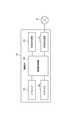
- FIG. 2is a block diagram showing a functional configuration of the control server 2.
- the control server 2includes a control server control unit 20 (control unit), a control server communication unit 21, and a control server storage unit 22.
- the control server control unit 20includes a CPU, a ROM, a RAM, and other peripheral circuits, and controls each unit of the control server 2.
- the control server control unit 20controls each unit of the control server 2 by cooperation of hardware and software, such as the CPU reading out and executing a control program stored in the ROM, for example.
- the control server communication unit 21accesses the network N and communicates with devices connected to the network N according to a predetermined communication standard under the control of the control server control unit 20.
- the control server storage unit 22includes non-volatile memory, and rewritably stores various data.
- the control server storage unit 22stores a station management database 22a, a map database 22b, and a user management database 22c.
- the station management database 22a and the user management database 22cwill be described later.
- the map database 22 bincludes at least information concerning search of a route in the map and guidance of the route.
- the map database 22bincludes node information having information on nodes corresponding to connection points in a road network such as an intersection, and link information having information on links corresponding to roads formed between the nodes and the nodes. Etc.
- FIG. 3is a block diagram showing a functional configuration of the in-vehicle apparatus 3.
- the on-vehicle apparatus 3includes an on-vehicle apparatus control unit 30, an on-vehicle apparatus storage unit 31, an on-vehicle apparatus communication unit 32, a GPS unit 33, a relative direction detection unit 34, a touch panel 35, and an on-vehicle apparatus 3. And a device communication interface 36.
- the in-vehicle device control unit 30includes a CPU, a ROM, a RAM, and other peripheral circuits, and controls each unit of the in-vehicle device 3.
- the on-vehicle device control unit 30controls the respective units of the on-vehicle device 3 by cooperation of hardware and software, such as the CPU reading and executing a control program stored in the ROM, for example.
- the in-vehicle device storage unit 31includes a non-volatile memory and stores various data.
- the in-vehicle device storage unit 31stores map data 31 a.
- the map data 31arelates to display of a map such as road drawing data relating to drawing of a road shape, background drawing data relating to drawing of a background such as terrain, and character string drawing data relating to drawing of a character string such as an administrative section Includes drawing data. Further, the map data 31a includes at least a part of the information included in the map database 22b described above.
- the map data 31acan be configured to include a search for a route in the map and information related to the route guidance. More specifically, the map data 31a can be configured to include node information, search for a route such as link information, and information related to route guidance.
- the map data 31amay also include information on facilities on the map.
- the in-vehicle device communication unit 32accesses the network N and communicates with devices (including the control server 2) connected to the network N according to a predetermined communication standard according to the control of the in-vehicle device control unit 30.
- Any communication standardmay be used for communication between the in-vehicle device 3 and the control server 2.
- the communication standardis, for example, HTTP or WebSocket.
- the in-vehicle device 3has a function of accessing the network N, and can communicate with devices connected to the network N.
- the in-vehicle apparatus 3may have a configuration in which the in-vehicle apparatus 3 does not have the function but communicates with an external apparatus having a function of accessing the network N and accesses the network N via the external apparatus.
- the in-vehicle device 3performs near field communication with an apparatus (for example, a so-called smartphone or a tablet computer) owned by a user who board the vehicle S, and accesses the network N via the apparatus. Good.
- the GPS unit 33receives GPS radio waves from GPS satellites via a GPS antenna (not shown), and detects the current position and the traveling direction of the vehicle S by calculation from the GPS signals superimposed on the GPS radio waves.
- the GPS unit 33outputs the detection result to the in-vehicle device control unit 30.
- the relative orientation detection unit 34includes a gyro sensor and an acceleration sensor.
- the gyro sensoris constituted by, for example, a vibration gyro, and detects a relative orientation (for example, a turning amount in the yaw axis direction) of the vehicle S.
- the acceleration sensordetects an acceleration acting on the vehicle S (for example, the inclination of the vehicle S with respect to the traveling direction).
- the relative orientation detection unit 34outputs the detection result to the in-vehicle device control unit 30.
- the in-vehicle device control unit 30detects the current position of the vehicle S based on the input from the GPS unit 33 and the relative direction detection unit 34 and the map data 31 a according to the user's instruction or the like. Note that any method may be used to detect the current position of the vehicle S, and information other than the information exemplified above such as information indicating the vehicle speed may be used in the detection. Further, the in-vehicle device control unit 30 searches for a route from the current position of the detected vehicle S to a destination set by the user based on the map data 31a in accordance with the user's instruction or the like. In addition, the in-vehicle device control unit 30 displays the route to the destination on the map and displays the detected current position of the vehicle S on the map according to the user's instruction or the like, and reaches the destination Guide the route of
- the touch panel 35includes a display device such as a liquid crystal display panel or an organic EL display panel, and displays information on the display device under the control of the in-vehicle device control unit 30.
- the touch panel 35includes a touch sensor, and outputs a signal indicating the position of the touch operation to the in-vehicle device control unit 30 when the touch operation is performed.
- the in-vehicle device control unit 30executes corresponding processing based on the signal indicating the contact position input from the touch sensor.
- the on-vehicle apparatus communication interface 36communicates with the vehicle control apparatus 13 according to a predetermined communication standard under the control of the on-vehicle apparatus control unit 30.
- FIG. 4is a block diagram showing a functional configuration of the management device 4.
- the management device 4includes a management device control unit 40, a management device communication unit 41, a management device storage unit 42, and a management device communication interface 43.
- the management device control unit 40includes a CPU, a ROM, a RAM, and other peripheral circuits, and controls each unit of the control server 2.
- the management device control unit 40controls the respective units of the management device 4 by cooperation of hardware and software, such as the CPU reading and executing the control program stored in the ROM, for example.
- the management device communication unit 41accesses the network N and communicates with devices connected to the network N in accordance with a predetermined communication standard.
- the management device storage unit 42includes a non-volatile memory, and rewritably stores various data.
- the management device storage unit 42stores a reservation management database 42a. The details of the reservation management database 42a will be described later.
- the management device communication interface 43communicates with devices connected to the management device 4 according to a predetermined communication standard under the control of the management device control unit 40. In the present embodiment, at least the charger 7, the battery exchange device 8, and the gate device 9 are connected to the management device 4.
- the vehicle Scarries the battery BT replaceably, and travels with the energy supplied by the battery BT. Then, the user needs to replace the battery BT at the battery station BS when the battery BT is low. Based on this, in the present embodiment, each device of the information processing system 1 executes the following processing for the replacement of the battery BT, and the replacement of the battery BT is performed at the appropriate battery station BS at an appropriate timing. Make it
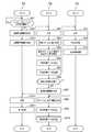
- FIG. 5is a flowchart showing the operation of each device of the information processing system 1.
- the flowchart FA of FIG. 5shows the operation of the on-vehicle apparatus 3, the flowchart FB shows the operation of the control server 2, and the flowchart FC shows the operation of the management apparatus 4.
- the in-vehicle device control unit 30 of the in-vehicle device 3periodically determines whether or not to start reservation of the battery station BS with an interval (step SA1). For example, the in-vehicle device control unit 30 performs the determination of step SA1 at one second intervals.
- step SA1the in-vehicle apparatus control unit 30 determines to start reservation of the battery station BS in the following case. That is, in step SA1, the in-vehicle device control unit 30 monitors whether or not the battery remaining amount of the mounted battery BTa falls below a predetermined threshold, and when the battery remaining amount falls below the predetermined threshold, the battery station It is determined that the reservation of the BS is started.
- the predetermined thresholdis a value such that replacement of the on-board battery BTa is recommended in order to reliably prevent an insufficient supply of energy when the battery remaining amount of the on-board battery BTa falls below the predetermined threshold.
- the in-vehicle device control unit 30periodically inquires of the vehicle control device 13 which manages the battery remaining amount of the mounted battery BTa, and recognizes the battery remaining amount based on the response to the inquiry.
- the configurationmay be such that the user is inquired as to whether or not the battery BT in the battery station BS is to be replaced when the battery remaining amount of the mounted battery BTa falls below a predetermined threshold.
- step SA1the in-vehicle apparatus control unit 30 determines that the reservation of the battery station BS is started when the user instructs to start the reservation of the battery station BS.
- the vehicle Sis provided with a meter for displaying the remaining amount of the battery BT. The user confirms the battery remaining amount displayed on the meter, and instructs start of the reservation of the battery station BS by a predetermined means as needed.
- step SA2When it is determined in step SA1 that reservation of the battery station BS is started (step SA1: YES), the in-vehicle device control unit 30 generates device related information J1 (step SA2).
- Device related information J1includes battery remaining amount information J2, vehicle position information J3, destination route information J4, vehicle type information J5, battery standard information J6, load state information J7, user identification information J8, and number information.
- the battery remaining amount information J2is information indicating the battery remaining amount.
- the in-vehicle device control unit 30communicates with the vehicle control device 13 to acquire the battery remaining amount information J2.
- the vehicle position information J3is information indicating the current position of the vehicle S.
- the in-vehicle device control unit 30acquires the vehicle position information J3 based on the input from the GPS unit 33, the input from the relative heading detection unit 34, and the map data 31a.
- the destination route information J4is information indicating a route to the destination when the destination is set. Specifically, the destination route information J4 corresponds to the road from the current position of the vehicle S to the destination. Is information indicating a combination of links.
- the destination route information J4is a null value when the destination is not set.
- the vehicle type information J5is information indicating the vehicle type of the vehicle S.
- the battery standard information J6is information indicating the standard of the battery BT that can be mounted on the vehicle S.
- the vehicle type information J5 and the battery standard information J6are registered in the in-vehicle device 3 in advance.
- the load state information J7is information indicating the state of the load. In the present embodiment, the load state information J7 is specifically information relating to the setting of the air conditioning apparatus provided in the vehicle S.
- the load state information J7includes at least information indicating a set temperature, information indicating an operation mode (heating, cooling, air blowing, etc.), and information indicating an air volume.
- the user identification information J8is information for uniquely identifying a user.
- the userin order to use the function of the control server 2 when reserving the battery station BS, the user needs to register as a member in advance for the service provided by a predetermined subject.
- the user identification information J8is allocated to the user and registered in the on-vehicle apparatus 3 by a predetermined means.
- the license plate information J9is information (information indicating a place name, classification information, hiragana information, and a series designation number) recorded on the license plate of the vehicle S.
- the license plate information J9is registered in the on-vehicle apparatus 3 in advance.
- the onboard device control unit 30controls the onboard device communication unit 32 to transmit the generated device related information J1 to the control server 2 (step SA3).
- the information regarding the communication required in order to transmit the apparatus relevant information J1 to the control server 2is registered in advance. This information may include, for example, an address of the control server 2, a communication standard used for communication, a format of data when transmitting the device related information J1, and the like.
- the control server control unit 20 of the control server 2controls the control server communication unit 21 to receive the device related information J1 (step SB1).
- the control server control unit 20performs user authentication and other necessary processes using the user identification information J8 included in the information.
- the user management database 22cstores information used for user authentication in association with the user identification information J8.
- the control server control unit 20appropriately communicates with the in-vehicle apparatus 3 using the information to authenticate the user.
- the recommendation station selection processis a process of selecting a battery station BS recommended to be used and generating information indicating a route to the battery station BS recommended to be used.
- the flowchart FD of FIG. 6is a flowchart showing details of the recommendation station selection process.
- the control server control unit 20determines whether or not the destination is set based on the destination route information J4 included in the received device related information J1 (step SD1). When the destination is not set (step SD1: NO), the control server control unit 20 refers to the station management database DB1 (step SD2).
- FIG. 7is a diagram showing information included in the record of the station management database DB1.
- the station management database DB1has a record for each battery station BS. Each record has station identification information J10, station position information J11, station structure information J12, and lane information J13.
- Station identification information J10is identification information that uniquely identifies battery station BS.
- the station position information J11is information indicating the position of the battery station BS.
- the station structure information J12is information on the structure of the battery station BS (a map of the battery station BS, information on lanes, etc.).
- Station structure information J12includes information necessary for generating station guidance information J27 described later.
- the lane information J13has lane related information J14 for each of the lanes L provided in the battery station BS.
- the lane related information J14has lane identification information J15, corresponding vehicle type information J16, corresponding standard information J17, and use time zone information J18.
- the lane identification information J15is identification information for uniquely identifying the lane L.
- the corresponding vehicle type information J16is information indicating a vehicle type capable of replacing the battery BT in the lane L. Vehicle types that can exchange the battery BT in the lane L are determined in advance so as to correspond to the size of the lane L, the standard of the battery exchange device 8, and the like.
- the corresponding standard information J17is information indicating the standard of the replaceable battery BT in the lane L.
- the use time zone information J18is information indicating a time zone in which the lane L is used.
- the time from the current date and time until the use of the lane L is predicted to completecorresponds to at least the time zone in which the lane L is used.
- the time zone in which the lane L is predicted to be used in the reservationcorresponds to the time zone in which the lane L is used.
- the management device control unit 40 of the management device 4manages the time zone in which the lane L is used for each of the lanes L provided in the battery station BS based on the reservation management database 42a. Do.
- the control server control unit 20periodically inquires of the management apparatus 4 about the time zone in which the lane L is used, and updates the value of the usage time zone information J18 based on the response to the inquiry.
- the control server control unit 20After referring to the station management database DB1 in step SD2, the control server control unit 20 specifies a candidate of the recommended battery station BS based on the referred station management database DB1 (step SD3).
- a candidate of the recommended battery station BSmay be simply referred to as a "candidate" as appropriate. More specifically, the control server control unit 20 controls the battery remaining amount information J2 and vehicle position information J3 included in the received device related information J1, station position information J11 included in each record of the station management database DB1, and map database 22b, the vehicle S identifies a reachable battery station BS without causing a shortage of the battery.
- control server control unit 20performs predetermined arithmetic processing based on the battery remaining amount information J2 and the vehicle position information J3 to allow the vehicle S to travel from the current position without causing shortage of the battery remaining amount.
- the control server control unit 20specifies the battery station BS belonging to the calculated travelable area based on the station position information J11 included in each record of the station management database DB1 and the map database 22b.
- the control server control unit 20executes the following processing for each of the identified battery stations BS, and determines whether or not to be a candidate.
- candidates to be subjected to the following processingare referred to as “target stations”.
- the control server control unit 20calculates the date and time when the vehicle S reaches the target station. Next, the control server control unit 20 can use the lane L available on the date and time when the vehicle S reaches the target station based on the use time zone information J18 that the record corresponding to the target station in the station management database DB1 has for each lane L. It is determined whether there is a. When there is no usable lane L, the control server control unit 20 does not set the target station as a candidate.
- the control server control unit 20controls the vehicle type information J5 included in the received device related information J1, the battery standard information J6, and the corresponding vehicle type information J16 that the record corresponding to the target station of the station management database DB1 has for each lane L. And, based on the corresponding standard information J17, it is determined whether or not there is a lane L in which the on-board battery BTa of the vehicle S can be replaced among the lanes L that can be used on the date and time when the vehicle S reaches the target station. . In the determination, if the lane L corresponds to the vehicle type of the vehicle S and the standard of the battery BT of the vehicle S, the control server control unit 20 changes the lane on which the mounted battery BTa of the vehicle S is replaced.
- the control server control unit 20determines that it is possible. If there is no lane L for which the battery BT can be replaced for the vehicle S, the control server control unit 20 does not set the target station as a candidate. On the other hand, when there is even one lane L in which the battery BT can be replaced for the vehicle S, the control server control unit 20 sets the target station as a candidate.
- control server control unit 20sets battery station BS as a candidate of battery station BS to select that can be reached without any shortage of remaining battery capacity of mounted battery BTa among battery stations BS. . According to this configuration, it is possible to effectively suppress the occurrence of the battery remaining capacity shortage before the vehicle S reaches the battery station BS. In addition, when selecting the recommended battery station BS, the control server control unit 20 manages the usage status of the battery station BS and reflects the usage status of the battery station BS. According to this configuration, occurrence of waiting time can be suppressed in the battery station BS, and the convenience of the user can be improved.
- the control server control unit 20selects a recommended battery station BS from the candidates (step SD4). More specifically, the control server control unit 20 preferentially selects the battery station BS closer to the current position of the vehicle S among the candidates. For example, the control server control unit 20 determines that the battery station BS is closer to the current position of the vehicle S as the linear distance connecting the current position of the vehicle S and the position of the battery station BS is shorter. Also, for example, the control server control unit 20 determines that the battery station BS is closer to the current position of the vehicle S as the travel distance of the vehicle S is shorter when the vehicle S travels to the battery station BS.
- the control server control unit 20recommends not only the relationship between the current position of the vehicle S and the position of the battery station BS, but also reflecting other factors that affect traveling until the battery station BS is reached.
- the battery station BSmay be selected. Other factors include, for example, the time required for the vehicle S to reach the battery station BS, the congestion of the road traveling to reach the battery station BS, and the size of the road facing the battery station BS. May be selected, and one or more of these elements may be selected.
- control server control unit 20selects the recommended battery station BS, reflecting the relationship between the position of the vehicle S and the position of the battery station BS, based on the received device related information J1. More specifically, control server control unit 20 preferentially selects a battery station BS located closer to the position of vehicle S. According to this configuration, user convenience can be improved.
- the battery station BS selected by the control server control unit 20 as a recommended battery station BSis referred to as a "recommended station”.
- control server control unit 20generates recommended station route information J20 indicating a route to the recommended station from the current position of the vehicle S based on the station management database 22a and the map database 22b (step SD5). . After the process of step SD5, the control server control unit 20 ends the recommendation station selection process.
- step SD1when it is determined in step SD1 that the destination is set (step SD1: YES), the control server control unit 20 refers to the station management database DB1 (step SD6).
- step SD6the control server control unit 20 specifies a candidate of a recommended station according to the following method based on the destination route information J4 included in the received device related information J1 and the station management database DB1 referenced in step SD6 ( Step SD7). That is, control server control unit 20 specifies battery stations BS within a predetermined range from the route to the destination as candidates for the recommendation station.
- control server control unit 20is a battery station when the separation distance between the route to the destination and the battery station BS is drawn, for example, from the battery station BS to a link corresponding to the route. Calculated by the distance between the BS and the intersection of the perpendicular and the link.
- control server control unit 20preferentially selects a battery station BS with a small delay in the timing of arrival of vehicle S at the destination as a recommended station.
- the control server control unit 20selects one or more battery stations BS passed through to reach the destination as a recommendation station from the candidates according to the following first to fourth rules (step SD8) .
- the first ruleis that by traveling to a destination via one or more battery stations BS selected as a recommendation station, it is possible to reach the destination without causing a shortage of battery charge. .
- the second ruleis to minimize the number of battery stations passing through to reach the destination. By selecting the recommendation station according to the second rule, it is possible to suppress the delay in the timing of reaching the destination due to the replacement of the battery BT via the battery station BS, and to improve the convenience for the user.
- the third ruleis that when the vehicle S reaches the battery station BS, it is recommended that the battery station BS have a vehicle type of the vehicle S and a lane L corresponding to the standard of the battery BT mountable on the vehicle S. It is a rule that it chooses as.
- the control server control unit 20when determining the conformity of the third rule, regarding the date and time when the vehicle S is predicted to reach the battery station BS of 1, another battery passed before passing through the battery station BS of 1 It also reflects the time required to replace the battery BT at the station BS.
- the fourth rulewhen the destination is reached, the battery remaining amount remains enough to reach any of the battery stations BS from the destination without causing a shortage of the battery remaining amount.
- the ruleis to By selecting the recommended station according to the fourth rule, it is possible to prevent the occurrence of battery shortage after reaching the destination.
- the control server control unit 20After selecting one or more recommendation stations, the control server control unit 20 aims from the current position of the vehicle S via one or more recommendation stations based on the station management database 22a and the map database 22b. Scheduling route information J21 indicating a route to the ground is generated (step SD9). After the process of step SD9, the control server control unit 20 ends the recommendation station selection process.
- the control server control unit 20executes the recommended station selection process and then carries out the vehicle S in the recommended stations (each of the plurality of recommended stations when a plurality of recommended stations are selected).
- the date and time (timing) of the arrival atis calculated (step SB3).
- the control server control unit 20selects one recommended station in the recommended station selection process. Although details are omitted, when a plurality of recommended stations are selected, the control server control unit 20 executes generation and transmission of reservation control data described below for each of the plurality of recommended stations.
- control server control unit 20generates reservation control data (control data) (step SB4). More specifically, in step SB4, the control server control unit 20 does not use the recommended station when the vehicle S reaches the recommended station, and the vehicle type of the vehicle S and the battery BT mountable on the vehicle S.
- the lane identification information J15 of any one lane L among the lanes L corresponding to the standardis acquired.
- the lane L corresponding to the acquired lane identification information J15is the lane L used by the vehicle S to replace the battery BT at the recommendation station.
- the lane L that the vehicle S uses to replace the battery BTis referred to as a “use lane”.
- the control server control unit 20includes the acquired lane identification information J15, arrival date and time information J22 indicating the date and time calculated in step SB3, and license plate information J9 included in the received device related information J1.
- the reservation control datainstructs the vehicle S corresponding to the license plate information J9 to use the lane L corresponding to the lane identification information J15 on the date and time indicated by the arrival date and time information J22.
- the reservation control datais such that the battery remaining amount of the storage battery BTb exchanged with the mounted battery BTa in the lane L corresponding to the lane identification information J15 becomes the target value (described later) by the date and time indicated by the arrival date and time information J22.
- control server control unit 20controls the control server communication unit 21 to transmit the reservation control data generated in step SB4 to the management device 4 provided in the recommendation station (step SB5).
- Information on communication necessary to transmit reservation control data to the management device 4is registered in advance. This information may include, for example, information on the address of the management apparatus 4 and the communication standard used for communication.
- the management device control unit 40 of the management device 4controls the management device communication unit 41 to receive reservation control data (step SC1).
- the management apparatus control unit 40registers one record corresponding to the reservation in the reservation management database 42a based on the received reservation control data (step SC2).
- FIG. 8is a diagram showing information included in the record of the reservation management database 42a.
- the records of the reservation management database 42ainclude lane identification information J15, reservation time zone information J24 (described later), and license plate information J9.
- the record of the reservation management database 42ahas user identification information J8 instead of the license plate information J9.
- step SC2based on the arrival date and time information J22 included in the reservation control data, the management device control unit 40 calculates a time zone in which the lane L corresponding to the lane identification information J15 included in the data is used. Information indicating the calculated time zone is reservation time zone information J24.
- the management device control unit 40manages the time required to replace the battery BT in each lane L.
- the time zone corresponding to the time starting from the arrival date and time information J22corresponds to the time zone in which the lane L is used. Do.
- the management apparatus control unit 40reserves a record having lane identification information J15 included in the reservation control data, reservation time zone information J24 indicating the calculated time zone, and license plate information J9 included in the reservation control data. Register in the management database 42a.
- the management device control unit 40executes the charge control process based on the received reservation control data (step SC3).
- step SC3the process of step SC3 will be described in detail.
- the storage battery BTb stored in the battery storage portion of the charger 7is controlled by the management device 4 so that while the battery storage portion is stored in the battery storage portion (while stored in the battery station BS), the remaining battery capacity is It is managed to be within a predetermined range (hereinafter referred to as "storage range").
- the storage rangecan suppress deterioration of the battery BT, and is a range in which the target value can be reached in a short time when charging of the battery BT is started.
- the target valueis a value exceeding the storage range, and is a sufficient value as the remaining amount of the battery BT newly mounted on the vehicle S. While the storage battery BTb is stored in the battery storage portion of the charger 7, by controlling the remaining amount of the storage battery BTb to be within the storage range, it is possible to appropriately suppress the deterioration of the battery BT, and When the battery is replaced with the on-board battery BTa, the battery remaining amount can be quickly set to the target value.
- the storage rangeis, for example, 40% to 60%, and the target value is, for example, 95%.
- the management device control unit 40controls the charger 7 provided in the lane L (use lane) corresponding to the lane identification information J15 included in the reservation control data, and is included in the data.
- the storage battery BTbis charged so that the battery remaining amount reaches the target value by the arrival date and time information J22. More specifically, the management apparatus control unit 40 sets the remaining battery amount to a target value so that the remaining battery amount of the storage battery BTb becomes a target value at a timing before a predetermined period from the date and time indicated by the arrival date and time information J22. Start charging for that purpose. Charging for the purpose of setting the remaining battery level to a target value may be performed by rapid charging.
- the timing before the predetermined period from the date and time indicated by the arrival date and time information J22is, for example, 10 minutes before the date and time, and, for example, one hour before the date and time.
- the management device control unit 40can calculate the time required for charging the storage battery BTb as the target value, calculates the time required for the charging, and calculates the timing for starting the charging based on the calculation result. . Then, the management device control unit 40 monitors whether or not the timing for monitoring the charging has arrived, and starts the charging when the timing has come. By performing such a process in the charge control process, it is possible to shorten the period in which charging for setting the storage battery BTb to the target value can be performed, and the battery remaining amount of the storage battery BTb is stored in the battery station BS. The period of time in which the condition is exceeded can be shortened, and the deterioration of the battery BT can be suppressed more effectively.
- the control server control unit 20after transmitting the reservation control data, the control server control unit 20 reliably transmits the vehicle S to the recommendation station based on the load state information J7 included in the received device related information J1. It is determined whether or not control of the load 11 (in the present embodiment, the air conditioner provided in the vehicle S) is necessary in order to make it reachable (step SB6). More specifically, the control server control unit 20 predicts the remaining battery charge of the onboard battery BTa when the vehicle S reaches the recommendation station. Next, the control server control unit 20 controls the load 11 when the predicted remaining amount of battery falls below a predetermined threshold value, and the energy consumed by the load 11 while the vehicle S is traveling toward the recommendation station.
- the load state information J7included in the received device related information J1. It is determined whether or not control of the load 11 (in the present embodiment, the air conditioner provided in the vehicle S) is necessary in order to make it reachable (step SB6). More specifically, the control server control unit 20 predicts the remaining battery charge of the onboard battery BTa when the vehicle S
- the vehicle Scan reliably reach the recommendation station.
- step SB6When it is determined in step SB6 that control of the load 11 is necessary (step SB6: YES), the control server control unit 20 consumes the load 11 based on the load state information J7 included in the received device related information J1.
- the load control information J26 for controlling the load 11 so as to reduce the energy consumptionis generated (step SB7).
- step SB7for example, the control server control unit 20 changes the set temperature to a predetermined temperature according to the operation mode of the air conditioner so that the energy consumed by the load 11 per unit time is reduced, and The load control information J26 for changing the air volume to a predetermined level is generated.
- step SB8the control server control unit 20 shifts the processing procedure to step SB8.
- step SB6determines the control of the load 11 is not necessary
- step SB8the control server control unit 20 generates station guidance information J27 based on the station structure information J12.
- Station guidance information J27is information used when guiding the user of the procedure for replacing the battery BT at the recommendation station.
- the station guidance information J27may include information indicating the address of the recommendation station, information indicating the telephone number of the recommendation station, and information indicating the name of the recommendation station.
- the on-vehicle apparatus 3displays information for guiding the user of the procedure for replacing the battery BT at the recommendation station, based on the station guidance information J27.
- the contents of the station guidance information J27will be described later through the description of the process executed by the in-vehicle device 3 based on the information.
- control server control unit 20generates guidance control data (step SB9).
- the guidance control dataincludes the recommended station route information J20 generated in step SD5 or the scheduling route information J21 generated in step SD9. Further, when the load control information J26 is generated in step SB7, the guidance control data includes the load control information J26.
- the guidance control dataalso includes the station guidance information J27 generated in step SB8.
- the guidance control data including the load control information J26corresponds to "control data for controlling the load 11 so that the energy consumed by the load 11 is reduced".
- control server control unit 20controls the control server communication unit 21 to transmit guidance control data to the on-vehicle apparatus 3 (step SB10).
- the in-vehicle apparatus control unit 30 of the in-vehicle apparatus 3controls the in-vehicle apparatus communication unit 32 to receive guidance control data (step SA4).
- the in-vehicle device control unit 30executes a guidance process based on the received guidance control data (step SA5).
- the flowchart FE of FIG. 9is a flowchart showing the details of the guidance process.
- the in-vehicle device control unit 30 of the in-vehicle device 3determines whether or not the received guidance control data includes the load control information J26 (step SE1).
- the load control information J26is not included (step SE1: NO)
- the in-vehicle device control unit 30shifts the processing procedure to step SE5.
- the on-vehicle apparatus control unit 30causes the touch panel 35 to set the temperature and the air volume to reduce the energy consumed for the air conditioner (load 11).
- the user interfaceis displayed to inquire whether or not to permit adjustment (step SE2). The user can make an input indicating that the adjustment is permitted or an input indicating that the adjustment is not permitted.
- step SE3determines whether there is an input indicating that the adjustment is permitted or an input indicating that the adjustment is not permitted.
- step SE3: “permit”the in-vehicle device control unit 30 outputs a control signal to the vehicle control device 13 based on the load control information J26. Are controlled (step SE4). As a result, the energy consumed by the load 11 (air conditioner) is reduced.
- step SE4the in-vehicle device control unit 30 shifts the processing procedure to step SE5.
- step SE3when there is an input indicating that the adjustment is not permitted (step SE3: “not permitted”), the in-vehicle device control unit 30 performs the processing procedure without executing the control of the load 11 based on the load control information J26. The process proceeds to step SE5.
- step SE5the in-vehicle device control unit 30 starts guidance of the route to the recommendation station based on the recommendation station route information J20 or the scheduling route information J21 included in the received guidance control data.
- the guidance control dataincludes the scheduling route information J21
- the in-vehicle device control unit 30starts the guidance of the route to the recommended station to pass next.
- step SE5the in-vehicle device control unit 30 displays a map of a predetermined scale on the touch panel 35 based on the map data 31a, and a mark indicating the current position of the vehicle S and the current position of the vehicle S on the map.
- the route to the recommendation stationis guided by displaying the route from the position to the recommendation station.
- a program having a function of guiding a route to the recommended stationis installed in the in-vehicle device 3 based on the recommended station route information J20 or the scheduling route information J21.
- the in-vehicle device control unit 30guides the route to the recommendation station by the function of the program.
- the in-vehicle device control unit 30monitors whether the vehicle S has reached the recommendation station (step SE6). If it is detected that the vehicle S has reached the recommendation station (step SE6: YES), the in-vehicle device control unit 30 stops the guidance of the route to the recommendation station and executes the following processing (step SE7). That is, based on the station guidance information J27 included in the received guidance control data, the in-vehicle device control unit 30 has a touch panel on the station guidance screen G1 on which information for guiding the vehicle S that has reached the recommendation station to the use lane Display on 35
- FIG. 10is a diagram showing an example of the station guidance screen G1. As shown in FIG. 10, a map of the recommendation station is displayed on the station guidance screen G1, and a route on which the vehicle S should travel to reach the use lane is displayed on the map at the recommendation station. By referring to the station guidance screen G1 displayed on the touch panel 35, the user can accurately recognize the route to the use lane.
- the gate device 9is provided at the entrance of each lane L of the battery station BS.
- the gate device 9has a circuit breaker that transitions between a state in which the entrance of the vehicle S into the lane L is blocked and a state in which the entry of the vehicle S into the lane L is permitted.
- the gate apparatus 9has a camera which can image
- the gate device 9has a display panel that allows a driver who enters the lane L to view.
- the management device control unit 40 of the management device 4periodically (eg, every one second) acquires captured image data based on the imaging result of the camera, and performs the following processing. That is, the management device control unit 40 analyzes the photographed image data, and determines whether the vehicle S has reached the entrance of the lane L or not. The determination is performed using an existing image recognition technology such as pattern matching. When it is detected that the vehicle S has reached the entrance of the lane L, the management device control unit 40 specifies the area of the license plate of the vehicle S in the photographed image data, performs character recognition on the area, and performs photographing. The license plate information J9 recorded on the registered license plate is acquired. Next, the management apparatus control unit 40 determines whether a reservation is registered for the vehicle S corresponding to the acquired license plate information J9 based on the reservation management database 42a.
- the management device control unit 40sets the circuit breaker to a state in which the entry of the vehicle S into the lane L is permitted, and permits the entry of the vehicle S into the lane L.
- the management device control unit 40displays, on the display panel, necessary matters such as notes on the replacement of the battery BT and a method of charging.
- the management device control unit 40sets the circuit breaker to the state of blocking the entry of the vehicle S into the lane L, and executes the corresponding processing. For example, the management device control unit 40 displays on the display panel a procedure necessary to replace the battery BT at the battery station BS, and causes the user to recognize the procedure.
- the control server 2includes the control server control unit 20 (control unit).
- the control server control unit 20is device related information J1 related to a vehicle S (drive device) on which a mounted battery BTa (mounted energy supply unit), which is a battery BT (energy supply unit) for supplying energy to the power source 10a, is replaceably mounted.
- the storage battery BTbstorage energy supply unit
- the storage battery BTbstorage energy supply unit
- the battery station BSis recommended to replace the battery BT.
- the control server 2reflects the inherent circumstances of the vehicle S based on the device related information J1 related to the vehicle S, and the battery station BS appropriate for the vehicle S to replace the battery BT is reflected. It can be selected. That is, according to the above configuration, the control server 2 can execute the processing corresponding to the replacement of the battery BT at the battery station BS.
- the remaining amount (remaining amount) of the storage battery BTbis managed by the management device 4 so as to be within the storage range (predetermined range) while being stored in the battery station BS. Then, when the control server control unit 20 selects the battery station BS, among the storage batteries BTb stored by the selected battery station BS, the remaining amount of the predetermined storage battery BTb becomes a target value exceeding the storage range. It sends reservation control data (control data) to the management device 4 to instruct. According to this configuration, it is possible to suppress the deterioration of storage battery BTb stored in battery station BS.
- control server control unit 20estimates the timing at which the battery BT is replaced in the selected battery station BS based on the device related information J1, and stores the predetermined storage before the estimated timing. Reservation control data for instructing the remaining amount of the battery BTb to be the target value is transmitted to the management device 4. According to this configuration, it is possible to make the remaining battery amount of the storage battery BTb to be replaced with the mounted battery BTa before the replacement of the battery BT is performed in the battery station BS.
- the vehicle Sis a mobile unit propelled by the energy supplied by the on-board battery BTa.
- the control server 2is characterized in that the mobile unit propelled by the energy supplied by the on-board battery BTa is propelled by the energy supplied by the on-board battery BTa based on the device related information J1 of the mobile body. Therefore, it is possible to select an appropriate battery station BS to replace the battery BT.
- the device related information J1includes information on the position of the vehicle S.
- the control server control unit 20selects the battery station BS, reflecting the relationship between the position of the vehicle S and the position of the battery station BS, based on the device related information J1.
- the control server 2can select an appropriate battery station BS reflecting the relationship between the position of the vehicle S and the position of the battery station BS.
- control server control unit 20preferentially selects the battery station BS located closer to the position of the vehicle S.
- the battery station BScan be more easily reached as the battery station BS is closer to the current position of the vehicle S. Based on this, according to the above configuration, the convenience of the user can be improved.
- the device related information J1includes information on the remaining battery capacity of the mounted battery BTa.
- the control server control unit 20sets, as the battery station BS, a battery station BS that can be reached by the vehicle S without reaching the battery remaining amount of the mounted battery BTa among the battery stations BS. According to this configuration, it is possible to suppress the shortage of the remaining battery charge before the vehicle S reaches the battery station BS.
- the device related information J1includes information on the route on which the vehicle S travels to the destination.
- the control server control unit 20selects the battery station BS, reflecting the route to the destination, based on the device related information J1. According to this configuration, the control server 2 can select an appropriate battery station BS reflecting the route to the destination.
- control server control unit 20preferentially selects the battery station BS with a small delay of the timing when the vehicle S reaches the destination. According to this configuration, it is possible to suppress the delay in the timing of reaching the destination due to the replacement of the battery BT via the battery station BS, and to improve the convenience for the user.
- the device related information J1includes information on the remaining battery capacity of the mounted battery BTa.
- the control server control unit 20performs one or more battery stations BS that replace the battery BT before reaching the destination so that the vehicle S reaches the destination without a shortage of the remaining battery capacity of the mounted battery BTa.
- the selected routeis scheduled via the selected one or more battery stations BS to the destination, and information indicating the scheduled route is transmitted to the on-vehicle device 3 (external device).
- the control server 2can suppress the occurrence of the battery remaining capacity shortage until the vehicle S reaches the destination.
- the device related information J1is provided in the vehicle S, and includes information on the load 11 driven by receiving the supply of energy from the onboard battery BTa, and information on the remaining amount of the onboard battery BTa.
- the control server control unit 20transmits guidance control data (control data) for controlling the load 11 to reduce the energy consumed by the load 11 to the in-vehicle device 3 (device mounted on the vehicle S) in a predetermined case. Do. According to this configuration, the control server 2 can more reliably prevent the shortage of the remaining battery amount from occurring until the vehicle S reaches the battery station BS.
- control server control unit 20manages the usage status of the battery station BS, and reflects the usage status of the battery station BS to select the battery station BS. According to this configuration, the control server 2 can suppress the occurrence of waiting time in the battery station BS, and can improve the convenience of the user.
- the vehicle Stravels with the energy supplied by the onboard battery BTa.
- the control server 2travels by the energy supplied by the onboard battery BTa based on the device related information J1 of the vehicle S for the vehicle S traveling by the energy supplied by the onboard battery BTa. Therefore, it is possible to select an appropriate battery station BS to replace the battery BT.
- the drive device for which the battery BT is to be replaced in the battery station BSis the vehicle S capable of traveling to the battery station BS by the energy supplied from the mounted battery BT.
- the replacement of the battery BT in the battery station BSis not performed by the drive device equipped with the battery BT traveling to the battery station BS by the energy supplied from the battery BT, It is done in the following way. That is, first, the mounting battery BTa is removed from the drive device at a position away from the battery station BS by the user.
- the userbrings the mounted battery BTa removed from the drive device to the battery station BS by a predetermined means, and exchanges the mounted battery BTa and the storage battery BTb at the battery station BS.
- the userbrings back the battery BT and attaches it to the drive device.
- the battery BTis replaced in the above-described manner. is assumed.
- the timing at which the battery BT is replaced in the battery station BSis determined because the user does not know by what means when and when the battery station BS arrives. I can not predict.
- the second embodimentwill be described by taking the case where the drive device is the cultivator K as an example.
- FIG. 11is a diagram showing the configuration of an information processing system 1b according to the second embodiment.
- the information processing system 1 bincludes a control server 2 connected to the network N, a management device 4, and a portable terminal 15.
- the portable terminal 15is a portable terminal that can be carried by the user, and is, for example, a smartphone, a tablet computer, or the like. However, the device corresponding to the portable terminal 15 does not have to be portable, and may be stationary.
- the portable terminal 15has a function of accessing the network N, and can communicate with devices (including the control server 2) connected to the network N.
- the cultivator Kmounts the battery BT replaceably, and the drive mechanism 50 is driven by the energy supplied from the battery BT to the power source 50a.
- the cultivator Kdoes not have a device having a function of accessing the network N (a device corresponding to the in-vehicle device 3 according to the first embodiment).
- FIG. 12is a block diagram showing a functional configuration of the portable terminal 15.
- the mobile terminal 15includes a mobile terminal control unit 60, a mobile terminal communication unit 61, a mobile terminal storage unit 62, a GPS unit 63, and a touch panel 64.
- the mobile terminal control unit 60includes a CPU, a ROM, a RAM, other peripheral circuits, and the like, and controls each unit of the mobile terminal 15.
- the portable terminal control unit 60controls each unit of the control server 2 by cooperation of hardware and software, such as the CPU reading and executing a control program stored in the ROM, for example.
- the mobile terminal communication unit 61accesses the network N and communicates with devices connected to the network N according to a predetermined communication standard.
- the portable terminal storage unit 62includes a non-volatile memory and stores various data in a rewritable manner.
- the touch panel 64has the same function as the touch panel 35 of the in-vehicle apparatus 3 according to the first embodiment.
- the GPS unit 63has the same function as the GPS unit 33 of the in-vehicle apparatus 3 according to the first embodiment.
- FIG. 13shows the portable terminal 15, the control server 2, and the management device 4 when a user who wishes to replace the onboard battery BTa mounted on the cultivator K reserves the battery station BS using the function of the control server 2. It is a flowchart which shows operation
- the flowchart FF of FIG. 13shows the operation of the portable terminal 15, the flowchart FG shows the operation of the control server 2, and the flowchart FH shows the operation of the management device 4.
- the battery station BSin the battery station BS, replacement of the battery BT is manually performed in the lane L.
- attachment or detachment of the battery BT with respect to the battery accommodating part of the charger 7 provided in each lane Lcan also be performed automatically by the battery exchange apparatus 8, and a person can also do it manually.
- the userreserves the battery station BS according to the method described later, goes to the reserved lane L, and manually removes the battery BT (storage battery BTb) mounted on the charger 7 in the lane L and brings the battery carried
- the BT(mounting battery BTa) is accommodated in the battery accommodating portion of the charger 7.
- the useractivates a predetermined application installed on the portable terminal 15 owned by the user (step S1).
- the predetermined applicationhas a function of providing a user interface for inputting information necessary for reservation of the battery station BS, a function of communicating with the control server 2 and transmitting information necessary for reservation of the battery station BS, etc. Have.
- the predetermined applicationis provided by, for example, a predetermined entity that provides a service regarding reservation of the battery station BS.
- the userinstalls the predetermined application on the portable terminal 15 owned by the user in advance by a predetermined means.
- the portable terminal control unit 60 of the portable terminal 15displays the first user interface UI1 on the touch panel 64 by the function of the predetermined application. (Step SF1).
- FIG. 14is a diagram showing an example of the first user interface UI1.
- the first user interface UI1is referred to as an input field NR1 for inputting the user identification information J8 and information indicating the date and time of arrival at the battery station BS (hereinafter referred to as "scheduled arrival date and time information J30").
- the first user interface UI1includes a confirmation button BK1 for confirming the input to the input field NR1 to the input field NR3.
- the userinputs the user identification information J8 in the input field NR1, inputs the estimated arrival date and time information J30 in the input field NR2, inputs the battery standard information J6 in the input field NR3, and operates the confirm button BK1 (step S2) .
- the portable terminal control unit 60When detecting that the enter button BK1 has been operated, the portable terminal control unit 60 generates device related information J1 based on the information input to the first user interface UI1 (step SF2).
- the device related information J1includes user identification information J8, estimated arrival date and time information J30, battery standard information J6, and portable terminal position information J31.
- the portable terminal position information J31is information indicating the position of the portable terminal 15.
- the battery standard information J6is information indicating the battery BT that can be mounted on the cultivator K, and corresponds to "information on drive device".
- the portable terminal control unit 60acquires the user identification information J8, the estimated arrival date and time information J30, and the battery standard information J6 based on the input to the first user interface UI1.
- the portable terminal control unit 60acquires portable terminal position information J31 based on the input from the GPS unit 63.
- the portable terminal control unit 60controls the portable terminal communication unit 61 to transmit the generated device related information J1 to the control server 2 (step SF3).
- control server control unit 20 of the control server 2controls the control server communication unit 21 to receive the device related information J1 (step SG1).
- the control server control unit 20executes a recommended station selection process based on the received device related information J1 (step SG2).
- the control server control unit 20executes the following process to select a recommended station. That is, the control server control unit 20 controls the arrival scheduled date and time information J30 and the battery standard information J6 included in the received device related information J1, corresponding standard information J17 included in each record of the station management database 22a, and use time zone information Based on J18, the following lanes are considered as candidate stations for recommendation. That is, the control server control unit 20 is a battery having a lane L in which a battery BT which can be used on the date when the user arrives at the battery station BS and which can be mounted on the cultivator K is stored. The station BS is a candidate of a recommended station.
- the control server control unit 20preferentially selects the battery station BS at a position closer to the position indicated by the mobile terminal position information J31 as a recommendation station. .
- the position indicated by the portable terminal position information J31is the position of the user at the current time, and the battery can be easily searched by the user by selecting the battery station BS at a position near the current position of the user as the recommendation station. This is because the station BS can be more likely to be selected as a recommendation station.
- the control server control unit 20generates reservation control data (control data) (step SG3).
- the reservation control dataincludes user identification information J8, lane identification information J15 of used lanes, and estimated arrival date and time information J30, and indicates the following items. That is, the reservation control data instructs the user corresponding to the user identification information J8 to use the lane L corresponding to the lane identification information J15 on the date and time indicated by the estimated arrival date and time information J30. Further, the reservation control data instructs the remaining amount of the storage battery BTb to be replaced with the mounted battery BTa to be the target value in the lane L corresponding to the lane identification information J15 by the date and time indicated by the arrival scheduled date and time information J30. Do.
- the control server control unit 20acquires the lane identification information J15 of the used lane by the same method as the method described in the first embodiment. Next, the control server control unit 20 controls the control server communication unit 21 to transmit the reservation control data generated in step SG3 to the management device 4 provided in the recommendation station (step SG4).
- the management device control unit 40 of the management device 4controls the management device communication unit 41 to receive reservation control data (step SH1).
- the management apparatus control unit 40registers one record corresponding to the reservation in the reservation management database 42a based on the received reservation control data (step SH2). Specifically, based on the estimated arrival date and time information J30 included in the reservation control data, the management device control unit 40 calculates a time zone in which the lane L corresponding to the lane identification information J15 included in the data is used. .
- the management apparatus control unit 40reserves a record having lane identification information J15 included in reservation control data, reservation time zone information J24 indicating a calculated time zone, and user identification information J8 included in reservation control data. Register in the management database 42a.
- One record of the reservation management database 42ahas the license plate information J9 in the first embodiment, but has the user identification information J8 instead of the license plate information J9 in the second embodiment.
- the management device control unit 40executes charge control processing based on the received reservation control data (step SH3).
- the charge control process according to the second embodimentis the same process as the charge control process described in step SC3 of the first embodiment.
- the control server control unit 20After transmitting the reservation control data, the control server control unit 20 generates guidance control data (step SG5).
- the guidance control dataincludes station position information J11 and station guidance information J27.
- the station guidance information J27includes information indicating the address of the recommendation station, information indicating the telephone number of the recommendation station, and information indicating the name of the recommendation station.
- the control server control unit 20acquires station position information J11 based on the station management database 22a, and generates station guidance information J27.
- the control server control unit 20controls the control server communication unit 21 to transmit the guidance control data generated in step SG5 to the portable terminal 15 (step SG6).
- the portable terminal control unit 60 of the portable terminal 15controls the portable terminal communication unit 61 to receive guidance control data (step SF4).
- the portable terminal control unit 60displays the second user interface UI2 on the touch panel 64 by the function of the application based on the received guidance control data (step SF5).
- the usercan display the second user interface UI2 on the touch panel 64 at an arbitrary timing by performing a predetermined operation even after the second user interface UI2 is temporarily removed from display.
- FIG. 15is a diagram showing an example of the second user interface UI2.
- the information that the reservation of the battery station BS is completedis displayed on the second user interface UI2.
- information indicating the name of the reserved battery station BS (recommended station), information indicating an address, and information indicating a telephone numberare displayed on the second user interface UI2.
- a two-dimensional code CDis displayed on the second user interface UI2.
- the two-dimensional code CDis a code in which the user identification information J8 is recorded.
- the portable terminal control unit 60generates a two-dimensional code in which the user identification information J8 is recorded by the function of the application.
- a guidance start button BK2is displayed on the second user interface UI2.
- the guidance start button BK2is a button for instructing the start of guidance until the replacement of the battery BT.
- the portable terminal control unit 60switches the second user interface UI2 to start guidance until the battery BT is replaced.
- an external server devicewhich may be the control server 2
- information necessary for calculating the routefor example, station position information J11). Etc.
- the portable terminal control unit 60detects that the position of the portable terminal 15 has reached the position of the recommendation station, it stops the guidance of the route to the recommendation station, based on the station guidance information J27. Guide the user who arrived at the recommendation station to the use lane.
- the control server control unit 20displays the same screen as the station guidance screen G1 according to the first embodiment on the touch panel 64 to provide guidance to the used lane.
- the management device control unit 40 of the management device 4periodically (for example, every one second) acquires captured image data based on the imaging result of the camera that the gate device 9 has, and performs the following processing. That is, the management device control unit 40 analyzes the photographed image data, and determines whether or not a human who is not in the vehicle S has arrived at the entrance of the lane L. The determination is performed, for example, using an existing face recognition technology. When it is detected that a human who is not in the vehicle S has arrived at the entrance of the lane L, the management device control unit 40 displays the following information on the display panel of the gate device 9.
- the management device control unit 40displays information for instructing holding of the two-dimensional code CD toward the camera on the display panel.
- the userperforms a predetermined operation on the portable terminal 15 based on the information displayed on the display panel to display the second user interface UI2, and the portable terminal 15 in a state in which the second user interface UI2 is displayed. Hold the display surface of the towards the camera.
- the gate device 9may be configured to have a camera for a two-dimensional code CD in addition to the camera that captures the entrance of the lane L.
- the management device control unit 40acquires photographed image data based on photographing of the two-dimensional code CD, specifies an area of the two-dimensional code CD in the photographed image data, analyzes the area, and records the area in the two-dimensional code CD.
- the user identification information J8is acquired.
- the management apparatus control unit 40determines whether a reservation is registered for the user corresponding to the acquired user identification information J8 based on the reservation management database 42a. When the reservation is registered, the management apparatus control unit 40 sets the circuit breaker to a state in which entry of the vehicle S into the lane L is permitted (a state in which a person not in the vehicle S can enter the lane L), Allow the user to enter lane L.
- the management device control unit 40displays, on the display panel, necessary matters such as notes on the replacement of the battery BT and a method of charging.
- the management apparatus control unit 40sets the circuit breaker to a state in which the entry of the vehicle S into the lane L is blocked (a state in which a person who does not board the vehicle S can not enter).
- RunFor example, the management device control unit 40 displays on the display panel a procedure necessary to replace the battery BT at the battery station BS, and causes the user to recognize the procedure.
- replacement of the battery BT in the lane Lis appropriately performed by the user.
- a mediumsuch as a procedure for manually replacing the battery BT may be installed in the lane L.
- the usercan smoothly replace the battery BT at the appropriate battery station BS, and can suppress the deterioration of the battery BT stored in the battery station BS.
- the energy supply unitwas a storage battery.
- the energy supply unitdoes not have to be a storage battery, and may be a fuel cell or a biological cell. That is, the energy supply unit may be anything as long as it supplies energy to the power source and is replaceably mounted on the drive device.
- the control server 2functions as an information processing apparatus.
- the device functioning as the information processing deviceis not limited to the control server 2.
- the in-vehicle device 3 or the vehicle control device 13may function as an information processing device, and devices other than the control server 2 connectable to the in-vehicle device 3 function as an information processing device It is also good.
- devices other than the control server 2 connectable to the portable terminal 15may function as the information processing apparatus.
- the battery BTmay have an arithmetic processing function and a communication function, and the battery BT may function as an information processing apparatus.
- a plurality of devicesmay communicate with each other and cooperate with each other to function as an information processing device. In this case, a combination of a plurality of devices corresponds to an information processing device.
- the information processing apparatusmay be any apparatus as long as it can execute the same process as the process of the control server 2 described in each embodiment.
- a drive deviceis not restricted to the device illustrated by each embodiment.
- the replacement of the battery BT performed in the battery station BSis automatically performed by the battery replacing device 8 in the first embodiment as an example, and the user manually in the second embodiment.
- the method of replacing the battery BTis not limited to the illustrated method.
- the functional blocks of each device of the information processing system 1can be arbitrarily realized by hardware and software, and do not indicate a specific hardware configuration.
- the processing units of the flowchart shown in the figureare divided according to the main processing contents in order to make the processing of each device easy to understand.
- the present inventionis not limited by the method and name of division of the processing unit.
- the processing of each devicecan also be divided into more processing units according to the processing content.
- one processing unitcan be divided to include more processes. Further, the processing order of the above-described flowchart is not limited to the illustrated example as long as the same processing can be performed.
- control serverinformation processing apparatus
- management device7 charger 10 traveling mechanism (drive mechanism) 10a power source 11 load 11a power source 20 control server control unit (control unit) 50 Drive mechanism 50a Power source BS Battery station (facility) BT battery (energy supply unit) BTa mounted battery (mounted energy supply unit) BTb storage battery (storage energy supply unit) S Vehicle (Drive, Mobile) K cultivator (drive unit)
Landscapes
- Engineering & Computer Science (AREA)
- Power Engineering (AREA)
- Transportation (AREA)
- Mechanical Engineering (AREA)
- Remote Sensing (AREA)
- Radar, Positioning & Navigation (AREA)
- General Physics & Mathematics (AREA)
- Physics & Mathematics (AREA)
- Sustainable Energy (AREA)
- Automation & Control Theory (AREA)
- Life Sciences & Earth Sciences (AREA)
- Sustainable Development (AREA)
- Navigation (AREA)
- Traffic Control Systems (AREA)
- Electric Propulsion And Braking For Vehicles (AREA)
Abstract
Description
Translated fromJapanese本発明は、情報処理装置に関する。The present invention relates to an information processing apparatus.
従来、エネルギー供給ユニットを交換可能に搭載し、エネルギー供給ユニットの残量が少なくなった場合、残量が十分な別のエネルギー供給ユニットと交換することによって、エネルギーの供給不足を防止する駆動装置が知られている。例えば、特許文献1には、エネルギー供給ユニット(バッテリー20)を交換可能に搭載する駆動装置(車両10)、及び、駆動装置にエネルギー供給ユニットを着脱する装置についての記載がある。Heretofore, there has been provided a driving device which mounts an energy supply unit in a replaceable manner, and when the remaining amount of the energy supply unit decreases, by replacing it with another energy supply unit having a sufficient remaining amount, energy shortage is prevented. Are known. For example,
エネルギー供給ユニットの交換という手段でエネルギーの供給不足を防止する駆動装置について、エネルギー供給ユニットの交換は、残量が十分なエネルギー供給ユニットが保管された施設において行われることが想定される。しかしながら、エネルギー供給ユニットの交換が施設で行われることに対応した適切な処理を実行する技術については、従来、十分な開示はない。
本発明は、上述した事情に鑑みてなされたものであり、エネルギー供給ユニットの交換が施設で行われることに対応した処理を実行可能な情報処理装置を提供することを目的とする。With respect to a drive device that prevents an insufficient supply of energy by means of replacing the energy supply unit, it is assumed that the exchange of the energy supply unit is performed at a facility where the energy supply unit with a sufficient remaining amount is stored. However, there has been no prior disclosure of technology for performing appropriate processing in response to the replacement of energy supply units at a facility.
The present invention has been made in view of the above-described circumstances, and an object of the present invention is to provide an information processing apparatus capable of executing processing corresponding to replacement of an energy supply unit in a facility.
この明細書には、2016年11月1日に出願された日本国特許出願・特願2016-214385号の全ての内容が含まれる。
上記目的を達成するために、本発明の情報処理装置は、動力源にエネルギーを供給するエネルギー供給ユニットである搭載エネルギー供給ユニットを交換可能に搭載する駆動装置に関する装置関連情報を取得し、取得した前記装置関連情報に基づいて、前記搭載エネルギー供給ユニットと交換可能なエネルギー供給ユニットである保管エネルギー供給ユニットを保管し、前記保管エネルギー供給ユニットと前記搭載エネルギー供給ユニットとの交換を行うことが可能な施設のうち、エネルギー供給ユニットの交換を行うことを推奨する前記施設を選択する制御部を備えることを特徴とする。
本発明の構成によれば、情報処理装置は、駆動装置に関する装置関連情報に基づいて、駆動装置の固有の事情を反映して、駆動装置にとってエネルギーを供給ユニットの交換を行うことが適切な施設を選択することができる。すなわち、上記構成によれば、情報処理装置は、エネルギー供給ユニットの交換が施設で行われることに対応した処理を実行できる。This specification includes the entire contents of Japanese Patent Application No. 2016-214385 filed on November 1, 2016.
In order to achieve the above object, the information processing apparatus according to the present invention acquires and acquires apparatus related information related to a drive device on which a mounted energy supply unit which is an energy supply unit for supplying energy to a power source is replaceably mounted. Based on the device related information, it is possible to store a storage energy supply unit which is an energy supply unit replaceable with the on-board energy supply unit, and exchange the storage energy supply unit and the on-board energy supply unit It is characterized by including a control part which chooses the above-mentioned institution which recommends exchanging energy supply units among institutions.
According to the configuration of the present invention, the information processing apparatus is an appropriate facility for replacing the energy supply unit for the drive device, reflecting the specific circumstances of the drive device based on the device related information on the drive device. Can be selected. That is, according to the above configuration, the information processing apparatus can execute the processing corresponding to the replacement of the energy supply unit in the facility.
また、本発明は、前記保管エネルギー供給ユニットの残量は、前記施設に保管される間、所定の範囲内となるように管理装置により管理され、前記制御部は、前記施設を選択した場合、選択した前記施設が保管する前記保管エネルギー供給ユニットのうち、所定の前記保管エネルギー供給ユニットの残量が前記所定の範囲を上回る目標値となるように指示する制御データを前記管理装置に送信することを特徴とする。
本発明の構成によれば、施設において保管される保管エネルギー供給ユニットの劣化を抑制できる。Further, in the present invention, when the remaining amount of the storage energy supply unit is managed by the management device so as to be within a predetermined range while being stored in the facility, and the control unit selects the facility, Transmitting, to the management apparatus, control data instructing that the remaining amount of a predetermined stored energy supply unit among the stored energy supply units stored by the selected facility be a target value exceeding the predetermined range; It is characterized by
According to the configuration of the present invention, the deterioration of the storage energy supply unit stored in the facility can be suppressed.
また、本発明は、前記制御部は、前記装置関連情報に基づいて、選択した前記施設でエネルギー供給ユニットの交換が行われるタイミングを推測し、推測したタイミングの前に、所定の前記保管エネルギー供給ユニットの残量が前記目標値となるように指示する制御データを前記管理装置に送信することを特徴とする。
本発明の構成によれば、施設においてエネルギー供給ユニットの交換が行われる前に、搭載エネルギー供給ユニットと交換される保管エネルギー供給ユニットについて、残量を十分な状態とすることができる。Further, according to the present invention, the control unit estimates the timing at which the energy supply unit is replaced in the selected facility based on the device related information, and the predetermined stored energy supply is performed before the estimated timing Control data for instructing the remaining amount of the unit to be the target value may be transmitted to the management apparatus.
According to the configuration of the present invention, it is possible to set the remaining amount of the storage energy supply unit to be replaced with the on-site energy supply unit before the energy supply unit is replaced in the facility.
また、本発明は、前記駆動装置は、前記搭載エネルギー供給ユニットにより供給されるエネルギーによって推進する移動体であることを特徴とする。
本発明の構成によれば、情報処理装置は、搭載エネルギー供給ユニットにより供給されるエネルギーによって推進する移動体について、移動体の装置関連情報に基づいて、搭載エネルギー供給ユニットにより供給されるエネルギーによって推進するという特性を反映して、エネルギー供給ユニットの交換を行うことが適切な施設を選択することができる。Further, the present invention is characterized in that the drive device is a mobile unit propelled by energy supplied by the on-board energy supply unit.
According to the configuration of the present invention, the information processing apparatus is promoted by the energy supplied by the on-board energy supply unit, based on the device related information of the mobile body, for the moving body promoted by the energy supplied by the on-board energy supply unit. It is possible to select an appropriate facility to replace the energy supply unit, reflecting
また、本発明は、前記装置関連情報は、前記移動体の位置に関する情報を含み、前記制御部は、前記装置関連情報に基づいて、前記移動体の位置と、前記施設の位置との関係を反映して、前記施設を選択することを特徴とする。
本発明の構成によれば、情報処理装置は、移動体の位置と、施設の位置との関係を反映した適切な施設を選択できる。Further, according to the present invention, the device related information includes information on the position of the movable body, and the control unit determines the relationship between the position of the movable body and the position of the facility based on the device related information. It reflects, and it is characterized by selecting the said institution.
According to the configuration of the present invention, the information processing apparatus can select an appropriate facility reflecting the relationship between the position of the mobile unit and the position of the facility.
また、本発明は、前記制御部は、前記移動体の位置から近い位置の前記施設ほど、優先して選択する。
ここで、移動体の現在の位置から近い施設ほど、簡易に施設に到達できるものと想定される。このことを踏まえ、本発明の構成によれば、ユーザーの利便性を向上できる。Further, in the present invention, the control unit preferentially selects the facilities located closer to the position of the mobile body.
Here, it is assumed that facilities closer to the current position of the mobile can be reached more easily. Based on this, according to the configuration of the present invention, the convenience of the user can be improved.
また、本発明は、前記装置関連情報は、前記搭載エネルギー供給ユニットの残量に関する情報を含み、前記制御部は、前記施設のうち、前記移動体が前記搭載エネルギー供給ユニットの残量不足が生じることなく到達可能な前記施設を、選択する前記施設の候補とすることを特徴とする。
本発明の構成によれば、移動体が施設に到達する前に、残量不足が生じることを抑制できる。Further, in the present invention, the device related information includes information on the remaining amount of the on-board energy supply unit, and the control unit causes the mobile unit to run out of the remaining on-board energy supply unit in the facility. The present invention is characterized in that the facilities which can be reached without being selected as candidates for the facilities to be selected.
According to the configuration of the present invention, it is possible to suppress the shortage of the remaining amount before the mobile body reaches the facility.
また、本発明は、前記装置関連情報は、目的地に至るまでに前記移動体が走行する経路に関する情報を含み、前記制御部は、前記装置関連情報に基づいて、目的地までの経路を反映して、前記施設を選択することを特徴とする。
本発明の構成によれば、情報処理装置は、目的地までの経路を反映した適切な施設を選択できる。Further, according to the present invention, the device related information includes information on a route along which the mobile unit travels to the destination, and the control unit reflects the route to the destination based on the device related information. And selecting the facility.
According to the configuration of the present invention, the information processing apparatus can select an appropriate facility reflecting the route to the destination.
また、本発明は、前記制御部は、目的地に前記移動体が到達するタイミングの遅延が小さい前記施設ほど、優先して選択することを特徴とする。
本発明の構成によれば、施設を経由してエネルギー供給ユニットの交換を行なうことに起因した目的地に到達するタイミングの遅延を抑制でき、ユーザーの利便性を向上できる。Further, the present invention is characterized in that the control unit preferentially selects the facility having a smaller delay of the timing at which the mobile body reaches the destination.
According to the configuration of the present invention, it is possible to suppress the delay in the timing of reaching the destination due to the replacement of the energy supply unit via the facility, and to improve the convenience of the user.
また、本発明は、前記装置関連情報は、前記搭載エネルギー供給ユニットの残量に関する情報を含み、前記制御部は、前記搭載エネルギー供給ユニットの残量不足が生じることなく前記移動体が目的地に到達するように、目的地に至るまでにエネルギー供給ユニットの交換を行う1又は複数の前記施設を選択し、選択した1又は複数の前記施設を経由して前記目的地に至る経路をスケジュールし、スケジュールした経路を示す情報を外部の装置に送信することを特徴とする。
本発明の構成によれば、情報処理装置は、移動体が目的地に至るまでに残量不足が発生することを抑制できる。Further, according to the present invention, the device related information includes information on the remaining amount of the on-board energy supply unit, and the control unit is configured to set the mobile unit to a destination without causing shortage of the on-board energy supply unit. To reach the destination, select one or more of the facilities for which the energy supply unit is to be replaced up to the destination, and schedule a route to the destination via the selected one or more of the facilities, It is characterized in that information indicating a scheduled route is transmitted to an external device.
According to the configuration of the present invention, the information processing apparatus can suppress the occurrence of shortage of the remaining amount until the moving object reaches the destination.
また、本発明は、前記装置関連情報は、前記移動体に設けられ、前記搭載エネルギー供給ユニットからエネルギーの供給を受けて駆動する負荷に関する情報と、前記搭載エネルギー供給ユニットの残量に関する情報とを含み、前記制御部は、所定の場合、前記負荷が消費するエネルギーが低減するように前記負荷を制御する制御データを、前記移動体に搭載された装置に送信することを特徴とする。
本発明の構成によれば、情報処理装置は、移動体が施設に到達するまでに残量不足が生じることを、より確実に防止できる。Further, according to the present invention, the device related information includes information on a load provided to the moving body and driven by receiving the supply of energy from the on-board energy supply unit, and information on the remaining amount of the on-board energy supply unit. The control unit may, in a predetermined case, transmit control data for controlling the load so as to reduce energy consumed by the load, to a device mounted on the mobile unit.
According to the configuration of the present invention, the information processing apparatus can more reliably prevent the shortage of the remaining amount from occurring until the mobile body reaches the facility.
また、本発明は、前記制御部は、前記施設の利用状況を管理し、前記施設の利用状況を反映して前記施設を選択することを特徴とする。
本発明の構成によれば、情報処理装置は、施設において、待ち時間が発生することを抑制でき、ユーザーの利便性を向上できる。Further, the present invention is characterized in that the control unit manages the use status of the facility, and reflects the use status of the facility to select the facility.
According to the configuration of the present invention, the information processing apparatus can suppress the occurrence of the waiting time in the facility, and can improve the convenience of the user.
また、本発明は、前記駆動装置は、前記搭載エネルギー供給ユニットにより供給されるエネルギーによって走行する車両であることを特徴とする。
本発明の構成によれば、情報処理装置は、搭載エネルギー供給ユニットにより供給されるエネルギーによって走行する車両について、車両の装置関連情報に基づいて、搭載エネルギー供給ユニットにより供給されるエネルギーによって走行するという特性を反映して、バッテリーBTの交換を行うことが適切な施設を選択することができる。Further, the present invention is characterized in that the drive device is a vehicle traveling by energy supplied by the on-board energy supply unit.
According to the configuration of the present invention, the information processing apparatus travels by the energy supplied by the on-board energy supply unit, based on the apparatus related information of the vehicle, for the vehicle traveling by the energy supplied by the on-board energy supply unit It is possible to select an appropriate facility to replace the battery BT, reflecting the characteristics.
本発明によれば、エネルギー供給ユニットの交換が施設で行われることに対応した処理を実行可能な情報処理装置を提供できる。According to the present invention, it is possible to provide an information processing apparatus capable of executing a process corresponding to the replacement of the energy supply unit in a facility.
以下、図面を参照して本発明の実施形態について説明する。
<第1実施形態>
図1は、本実施形態に係る情報処理システム1の構成を示す図である。
図1に示すように、情報処理システム1は、インターネットや電話網を含んで構成されるネットワークNと接続可能な制御サーバー2(情報処理装置)を備える。制御サーバー2は、車載装置3、及び管理装置4と通信可能なサーバー装置である。図1では、制御サーバー2を1つのブロックで表すが、これは、制御サーバー2が、単一のサーバー装置により構成されることを意味するものではない。制御サーバー2は、複数のサーバー装置を含んで構成されたものでもよく、所定のシステムの一部であってもよい。すなわち、制御サーバー2は、以下で説明する機能を有していれば、その形態はどのようなものであってもよい。また、詳細は省略するが、制御サーバー2と、車載装置3、及び管理装置4との間では、所定の暗号化技術、その他のセキュリティーに関する技術により、セキュアな通信が行われる。
以下、制御サーバー2の機能を利用する者を総称して、「ユーザー」と表現する。ユーザーには、車載装置3に搭乗する者(運転手に限らない。)が含まれる。Hereinafter, embodiments of the present invention will be described with reference to the drawings.
First Embodiment
FIG. 1 is a diagram showing the configuration of an
As shown in FIG. 1, the
Hereinafter, a person who uses the function of the
図1に示すように、情報処理システム1は、車両S(駆動装置)(移動体)に搭載された車載装置3を備える。
本実施形態に係る車両Sは、バッテリーBTを交換可能に搭載し、バッテリーBTから供給されるエネルギーに基づいて走行(推進)する電気自動車である。
図1に示すように、車両Sは、走行機構10と、負荷11と、エネルギー供給部12とを備える。
走行機構10は、車両Sを走行させる機構や、車両Sに実装された機構(例えば、ワイパーや、ウインカー等。)であり、電動機を含んで構成された動力源10aによって駆動する。
負荷11は、車両Sの車内の空気を調和する空気調和機、その他の車両Sに搭載された機構であり、電動機を含んで構成された動力源11aによって駆動する。As shown in FIG. 1, the
The vehicle S according to the present embodiment is an electric vehicle that has the battery BT mounted thereon in a replaceable manner and travels (promotes) based on energy supplied from the battery BT.
As shown in FIG. 1, the vehicle S includes a traveling
The traveling
The
バッテリーBTは、エネルギーを供給する蓄電池である。エネルギー供給部12は、車両Sに搭載されたバッテリーBTから、少なくとも、動力源10a、及び動力源11aにエネルギーを供給する。
本実施形態に係る車両Sでは、エネルギーの消費に伴ってバッテリーBTのバッテリー残量(残量)が少なくなった場合、バッテリー残量が十分なバッテリーBTと交換されることによって、バッテリー残量不足(エネルギーの供給不足)が防止される。これにより、バッテリーBTのバッテリー残量が少なくなった場合にバッテリーBTを充電するタイプの電気自動車と比較して、車両Sに搭載されたバッテリーBTのバッテリー残量を十分な状態とするまでに要する時間が短くて済み、この点で、ユーザーの利便性が高い。
以下、適宜、車両Sに搭載された状態のバッテリーBTを、「搭載バッテリーBTa」(搭載エネルギー供給ユニット)と表現し、便宜的に、後述する「保管バッテリーBTb」(保管エネルギー供給ユニット)と区別する。The battery BT is a storage battery that supplies energy. The
In the vehicle S according to the present embodiment, when the battery remaining amount (remaining amount) of the battery BT decreases with the consumption of energy, the battery remaining amount is insufficient, by replacing with the battery BT having a sufficient remaining amount. (Insufficient supply of energy) is prevented. As a result, compared to an electric car of a type that charges the battery BT when the battery remaining amount of the battery BT decreases, it takes until the battery remaining amount of the battery BT mounted on the vehicle S is brought into a sufficient state. The time is short, and in this respect, the user's convenience is high.
Hereinafter, the battery BT mounted on the vehicle S is referred to as “mounted battery BTa” (mounted energy supply unit), and is distinguished from “stored battery BTb” (stored energy supply unit) described later for convenience. Do.
図1に示すように、車両Sは、車両制御装置13を備える。車両制御装置13は、ECU(engine control unit)を含んで構成され、少なくとも走行機構10、及び負荷11に制御信号を出力して、これら機構を制御する。
図1に示すように、車両Sには、車載装置3が搭載される。車載装置3は、車両Sのダッシュボード等に設けられたカーナビゲーションである。
車載装置3は、例えば、車両Sの現在の位置を検出する自車位置検出を行う機能を有する。また、車載装置3は、地図上に車両Sの現在の位置を表示する車両位置表示を行う機能を有してもよい。また、車載装置3は、目的地までの経路を探索する経路探索を行う機能を有してもよい。また、車載装置3は、地図を表示して、地図上に目的地までの経路を表示し目的地までの経路を案内する経路案内を行う機能を有してもよく、その他の機能を有してもよい。なお、車載装置3は、カーナビゲーションに限らず、後述する機能を有する装置であれば何でもよい。
車載装置3は、ネットワークNにアクセスする機能を有し、制御サーバー2と通信可能である。また、車載装置3と、車両制御装置13とは通信可能に接続される。As shown in FIG. 1, the vehicle S includes a
As shown in FIG. 1, an on-
The in-
The in-
図1に示すように、情報処理システム1は、バッテリーステーションBSに設けられた管理装置4を備える。
バッテリーステーションBSは、車両SのバッテリーBTの交換を行なうことが可能な施設である。バッテリーステーションBSには、車両Sに搭載された搭載バッテリーBTaと交換可能なバッテリーBTが保管される。以下、バッテリーステーションBSに保管された状態のバッテリーBTを、「保管バッテリーBTb」(保管エネルギー供給ユニット)という。車両Sの運転手(ユーザー)は、バッテリーステーションBSで、搭載バッテリーBTaと、保管バッテリーBTbとを交換することができる。本実施形態では、後述するように、制御サーバー2の機能より、ユーザーは、バッテリーステーションBSでのバッテリーBTを適切なタイミングで円滑に行なうことができる。
バッテリーステーションBSには、1又は複数のレーンLが設けられる。バッテリーBTの交換は、レーンLにおいて行なわれる。As shown in FIG. 1, the
Battery station BS is a facility capable of replacing battery BT of vehicle S. In the battery station BS, a battery BT mounted on the vehicle S and a battery BT replaceable are stored. Hereinafter, the battery BT stored in the battery station BS is referred to as “storage battery BTb” (storage energy supply unit). The driver (user) of the vehicle S can exchange the on-board battery BTa and the storage battery BTb at the battery station BS. In the present embodiment, as will be described later, the user can smoothly carry out the battery BT at the battery station BS at an appropriate timing by the function of the
The battery station BS is provided with one or more lanes L. The replacement of the battery BT is performed in the lane L.
管理装置4は、ネットワークNにアクセスする機能を有しており、ネットワークNに接続された機器(制御サーバー2を含む。)と通信することができる。
また、管理装置4は、レーンLごとに設けられた充電器7、バッテリー交換装置8、及びゲート装置9と通信可能に接続され、これら装置を制御する。
充電器7は、バッテリーBTを収容するバッテリー収容部(不図示)を備え、管理装置4の制御で、バッテリー収容部に収容されたバッテリーBTを充電する。充電器7によるバッテリーBTの充電については後述する。
バッテリー交換装置8は、レーンLにおいて、管理装置4の制御で、車両Sに搭載された搭載バッテリーBTaと、充電器7に収容された保管バッテリーBTbとの交換を自動で行なう。
ゲート装置9については、後述する。The
Further, the
The
The
The
図2は、制御サーバー2の機能的構成を示すブロック図である。
図2に示すように、制御サーバー2は、制御サーバー制御部20(制御部)と、制御サーバー通信部21と、制御サーバー記憶部22とを備える。
制御サーバー制御部20は、CPUや、ROM、RAM、その他周辺回路等を備え、制御サーバー2の各部を制御する。制御サーバー制御部20は、例えば、CPUが、ROMが記憶する制御プログラムを読み出して実行する等、ハードウェアとソフトウェアとの協働により、制御サーバー2の各部を制御する。
制御サーバー通信部21は、制御サーバー制御部20の制御で、所定の通信規格に従って、ネットワークNにアクセスし、ネットワークNに接続された機器と通信する。
制御サーバー記憶部22は、不揮発性メモリーを備え、各種データを書き換え可能に記憶する。制御サーバー記憶部22は、ステーション管理データベース22aと、地図データベース22bと、ユーザー管理データベース22cとを記憶する。ステーション管理データベース22a、及び、ユーザー管理データベース22cについては、後述する。地図データベース22bは、少なくとも、地図における経路の探索、及び、経路の案内に係る情報を含む。具体的には、地図データベース22bは、交差点等の道路網における結線点に対応するノードに関する情報を有するノード情報、ノードとノードとの間に形成される道路に対応するリンクに関する情報を有するリンク情報等を含む。FIG. 2 is a block diagram showing a functional configuration of the
As shown in FIG. 2, the
The control
The control
The control
図3は、車載装置3の機能的構成を示すブロック図である。
図3に示すように、車載装置3は、車載装置制御部30と、車載装置記憶部31と、車載装置通信部32と、GPSユニット33と、相対方位検出ユニット34と、タッチパネル35と、車載装置通信インターフェース36とを備える。FIG. 3 is a block diagram showing a functional configuration of the in-
As shown in FIG. 3, the on-
車載装置制御部30は、CPUや、ROM、RAM、その他周辺回路等を備え、車載装置3の各部を制御する。車載装置制御部30は、例えば、CPUが、ROMが記憶する制御プログラムを読み出して実行する等、ハードウェアとソフトウェアとの協働により、車載装置3の各部を制御する。
車載装置記憶部31は、不揮発性メモリーを備え、各種データを記憶する。車載装置記憶部31は、地図データ31aを記憶する。地図データ31aは、道路の形状の描画に係る道路描画データや、地形等の背景の描画に係る背景描画データ、行政区画等の文字列の描画に係る文字列描画データ等の地図の表示に係る描画データを含む。また、地図データ31aは、上述した地図データベース22bが有する情報の少なくとも一部を含む。地図データ31aは、地図における経路の探索、及び、経路の案内に係る情報を含む構成とすることができる。より具体的には、地図データ31aは、ノード情報や、リンク情報等の経路の探索、及び、経路の案内に係る情報を含む構成とすることができる。また、地図データ31aは、地図上の施設に関する情報を含んでもよい。The in-vehicle
The in-vehicle
車載装置通信部32は、車載装置制御部30の制御に従って、所定の通信規格に従って、ネットワークNにアクセスし、ネットワークNと接続する機器(制御サーバー2を含む。)と通信する。車載装置3と制御サーバー2との間での通信に用いられる通信規格は、何でもよい。通信規格は、例えば、HTTPや、WebSocketである。
本実施形態では、車載装置3は、ネットワークNにアクセスする機能を有しており、ネットワークNに接続された機器と通信することができる。ただし、車載装置3が当該機能を有さず、ネットワークNにアクセスする機能を有する外部の装置と通信し、当該外部の装置を介してネットワークNにアクセスする構成でもよい。例えば、車載装置3は、車両Sに搭乗するユーザーが所有する機器(例えば、いわゆるスマートフォンや、タブレット型のコンピューター。)と、近距離無線通信し、当該機器を介してネットワークNにアクセスしてもよい。The in-vehicle
In the present embodiment, the in-
GPSユニット33は、図示しないGPSアンテナを介してGPS衛星からのGPS電波を受信し、GPS電波に重畳されたGPS信号から、車両Sの現在位置と進行方向とを演算により検出する。GPSユニット33は、検出結果を車載装置制御部30に出力する。
相対方位検出ユニット34は、ジャイロセンサと、加速度センサとを備える。ジャイロセンサは、例えば振動ジャイロにより構成され、車両Sの相対的な方位(例えば、ヨー軸方向の旋回量)を検出する。加速度センサは、車両Sに作用する加速度(例えば、進行方向に対する車両Sの傾き)を検出する。相対方位検出ユニット34は、検出結果を車載装置制御部30に出力する。
車載装置制御部30は、ユーザーの指示等に応じて、GPSユニット33及び相対方位検出ユニット34からの入力、及び、地図データ31aに基づいて、車両Sの現在の位置を検出する。なお、車両Sの現在の位置を検出する方法はどのような方法であってもよく、また、検出に際し、車速を示す情報等の上記で例示した情報以外の情報を用いてもよい。また、車載装置制御部30は、ユーザーの指示等に応じて、地図データ31aに基づいて、検出した車両Sの現在の位置から、ユーザーに設定された目的地に至る経路を探索する。また、車載装置制御部30は、ユーザーの指示等に応じて、目的地までの経路を地図上に表示すると共に、検出した車両Sの現在の位置を地図上に表示し、目的地に至るまでの経路を案内する。The
The relative
The in-vehicle
タッチパネル35は、液晶表示パネルや有機EL表示パネル等の表示装置を備え、車載装置制御部30の制御で、表示装置に情報を表示する。
タッチパネル35は、タッチセンサーを備え、タッチパネル35が接触操作された場合、接触操作された位置を示す信号を車載装置制御部30に出力する。車載装置制御部30は、タッチセンサーから入力された接触位置を示す信号に基づいて、対応する処理を実行する。
車載装置通信インターフェース36は、車載装置制御部30の制御で、所定の通信規格に従って、車両制御装置13と通信する。The
The
The on-vehicle
図4は、管理装置4の機能的構成を示すブロック図である。
図4に示すように、管理装置4は、管理装置制御部40と、管理装置通信部41と、管理装置記憶部42と、管理装置通信インターフェース43とを備える。
管理装置制御部40は、CPUや、ROM、RAM、その他周辺回路等を備え、制御サーバー2の各部を制御する。管理装置制御部40は、例えば、CPUが、ROMが記憶する制御プログラムを読み出して実行する等、ハードウェアとソフトウェアとの協働により、管理装置4の各部を制御する。
管理装置通信部41は、管理装置制御部40の制御で、所定の通信規格に従って、ネットワークNにアクセスし、ネットワークNに接続された機器と通信する。
管理装置記憶部42は、不揮発性メモリーを備え、各種データを書き換え可能に記憶する。管理装置記憶部42は、予約管理データベース42aを記憶する。予約管理データベース42aについえは後述する。
管理装置通信インターフェース43は、管理装置制御部40の制御で、管理装置4に接続された機器と所定の通信規格に従って通信する。本実施形態では、管理装置4に、少なくとも、充電器7、バッテリー交換装置8、及び、ゲート装置9が接続される。FIG. 4 is a block diagram showing a functional configuration of the
As shown in FIG. 4, the
The management device control unit 40 includes a CPU, a ROM, a RAM, and other peripheral circuits, and controls each unit of the
Under the control of the management device control unit 40, the management
The management
The management
ところで、上述したように、車両Sは、バッテリーBTを交換可能に搭載し、バッテリーBTが供給するエネルギーによって走行する。そして、ユーザーは、バッテリーBTのバッテリー残量が少なくなった場合は、バッテリーステーションBSにおいて、バッテリーBTを交換する必要がある。これを踏まえ、本実施形態では、情報処理システム1の各装置が、バッテリーBTの交換に関して以下の処理を実行し、バッテリーBTの交換が、適切なタイミングで、適切なバッテリーステーションBSにおいて行なわれるようにする。By the way, as described above, the vehicle S carries the battery BT replaceably, and travels with the energy supplied by the battery BT. Then, the user needs to replace the battery BT at the battery station BS when the battery BT is low. Based on this, in the present embodiment, each device of the
図5は、情報処理システム1の各装置の動作を示すフローチャートである。
図5のフローチャートFAは車載装置3の動作を示し、フローチャートFBは制御サーバー2の動作を示し、フローチャートFCは管理装置4の動作を示す。FIG. 5 is a flowchart showing the operation of each device of the
The flowchart FA of FIG. 5 shows the operation of the on-
図5のフローチャートFAに示すように、車載装置3の車載装置制御部30は、バッテリーステーションBSの予約を開始するか否かを、間隔をあけて定期的に判別する(ステップSA1)。例えば、車載装置制御部30は、1秒間隔で、ステップSA1の判別を行なう。
ステップSA1において、車載装置制御部30は、以下の場合に、バッテリーステーションBSの予約を開始すると判別する。
すなわち、ステップSA1において、車載装置制御部30は、搭載バッテリーBTaのバッテリー残量が、所定の閾値を下回ったか否かを監視し、バッテリー残量が当該所定の閾値を下回った場合に、バッテリーステーションBSの予約を開始すると判別する。当該所定の閾値は、当該所定の閾値を搭載バッテリーBTaのバッテリー残量が下回った場合、エネルギーの供給不足を確実に防止するために、搭載バッテリーBTaの交換が推奨されるような値とされる。車載装置制御部30は、搭載バッテリーBTaのバッテリー残量を管理する車両制御装置13に対して定期的にバッテリー残量を問い合わせ、問い合わせに対する応答に基づいて、バッテリー残量を認識する。なお、搭載バッテリーBTaのバッテリー残量が所定の閾値を下回った場合に、バッテリーステーションBSにおけるバッテリーBTの交換を行なうか否かをユーザーに問い合わせる構成でもよい。
また、ステップSA1において、車載装置制御部30は、バッテリーステーションBSの予約を開始することについてユーザーから指示があった場合に、バッテリーステーションBSの予約を開始すると判別する。ここで、車両Sには、バッテリーBTのバッテリー残量を表示するメーターが設けられる。ユーザーは、メーターに表示されたバッテリー残量を確認し、必要に応じて、所定の手段で、バッテリーステーションBSの予約の開始を指示する。As shown in the flowchart FA of FIG. 5, the in-vehicle
In step SA1, the in-vehicle
That is, in step SA1, the in-vehicle
Further, in step SA1, the in-vehicle
ステップSA1で、バッテリーステーションBSの予約を開始すると判別した場合(ステップSA1:YES)、車載装置制御部30は、装置関連情報J1を生成する(ステップSA2)。
装置関連情報J1は、バッテリー残量情報J2と、車両位置情報J3と、目的地経路情報J4と、車種情報J5と、バッテリー規格情報J6と、負荷状態情報J7と、ユーザー識別情報J8と、ナンバープレート情報J9とを含む。
バッテリー残量情報J2は、バッテリー残量を示す情報である。車載装置制御部30は、車両制御装置13と通信し、バッテリー残量情報J2を取得する。
車両位置情報J3は、車両Sの現在の位置を示す情報である。車載装置制御部30は、GPSユニット33からの入力、相対方位検出ユニット34からの入力、及び地図データ31aに基づいて、車両位置情報J3を取得する。
目的地経路情報J4は、目的地が設定されている場合に、目的地までの経路を示す情報であり、具体的には、車両Sの現在の位置から、目的地に至るまでの道路に対応するリンクの組み合わせを示す情報である。目的地経路情報J4は、目的地が設定されていない場合は、ヌル値である。When it is determined in step SA1 that reservation of the battery station BS is started (step SA1: YES), the in-vehicle
Device related information J1 includes battery remaining amount information J2, vehicle position information J3, destination route information J4, vehicle type information J5, battery standard information J6, load state information J7, user identification information J8, and number information. And plate information J9.
The battery remaining amount information J2 is information indicating the battery remaining amount. The in-vehicle
The vehicle position information J3 is information indicating the current position of the vehicle S. The in-vehicle
The destination route information J4 is information indicating a route to the destination when the destination is set. Specifically, the destination route information J4 corresponds to the road from the current position of the vehicle S to the destination. Is information indicating a combination of links. The destination route information J4 is a null value when the destination is not set.
車種情報J5は、車両Sの車種を示す情報である。
バッテリー規格情報J6は、車両Sに搭載可能なバッテリーBTの規格を示す情報である。
車種情報J5、及び、バッテリー規格情報J6は、車載装置3に事前に登録される。
負荷状態情報J7は、負荷の状態を示す情報である。本実施形態では、負荷状態情報J7は、具体的には、車両Sに設けられた空気調和装置の設定に関する情報である。負荷状態情報J7は、設定温度を示す情報、運転モード(暖房や、冷房、送風等。)を示す情報、及び風量を示す情報を少なくとも含む。
ユーザー識別情報J8は、ユーザーを一意に識別する情報である。ここで、バッテリーステーションBSの予約に際し、制御サーバー2の機能を利用するためには、ユーザーは、所定の主体が提供するサービスに事前に会員登録する必要がある。当該サービスへの会員登録が完了すると、ユーザーにユーザー識別情報J8が割り振られ、所定の手段で車載装置3に登録される。
ナンバープレート情報J9は、車両Sのナンバープレートに記録された情報(地名を示す情報、分類情報、ひらがな情報、及び一連指定番号。)である。ナンバープレート情報J9は、車載装置3に事前に登録される。The vehicle type information J5 is information indicating the vehicle type of the vehicle S.
The battery standard information J6 is information indicating the standard of the battery BT that can be mounted on the vehicle S.
The vehicle type information J5 and the battery standard information J6 are registered in the in-
The load state information J7 is information indicating the state of the load. In the present embodiment, the load state information J7 is specifically information relating to the setting of the air conditioning apparatus provided in the vehicle S. The load state information J7 includes at least information indicating a set temperature, information indicating an operation mode (heating, cooling, air blowing, etc.), and information indicating an air volume.
The user identification information J8 is information for uniquely identifying a user. Here, in order to use the function of the
The license plate information J9 is information (information indicating a place name, classification information, hiragana information, and a series designation number) recorded on the license plate of the vehicle S. The license plate information J9 is registered in the on-
装置関連情報J1を生成した後、車載装置制御部30は、車載装置通信部32を制御して、生成した装置関連情報J1を、制御サーバー2に送信する(ステップSA3)。なお、制御サーバー2に装置関連情報J1を送信するために必要な通信に関する情報は、事前に登録される。この情報は、例えば、制御サーバー2のアドレスや、通信に使用する通信規格、装置関連情報J1を送信するときのデータのフォーマット等に関する情報を含んでもよい。After generating the device related information J1, the onboard
図5のフローチャートFBに示すように、制御サーバー2の制御サーバー制御部20は、制御サーバー通信部21を制御して、装置関連情報J1を受信する(ステップSB1)。
なお、制御サーバー制御部20は、装置関連情報J1の受信に応じて、当該情報に含まれるユーザー識別情報J8を用いて、ユーザーの認証、その他の必要な処理を行う。詳細には、ユーザー管理データベース22cには、ユーザー識別情報J8と対応付けて、ユーザーの認証に用いる情報が記憶される。制御サーバー制御部20は、当該情報を用いて、適宜、車載装置3と通信を行って、ユーザーを認証する。As shown in the flowchart FB of FIG. 5, the control
In addition, in response to the reception of the device related information J1, the control
次いで、制御サーバー制御部20は、推奨ステーション選択処理を実行する(ステップSB2)。推奨ステーション選択処理は、利用することを推奨するバッテリーステーションBSを選択し、利用することを推奨するバッテリーステーションBSまでの経路を示す情報を生成する処理である。Next, the control
図6のフローチャートFDは、推奨ステーション選択処理の詳細を示すフローチャートである。
図6のフローチャートFDに示すように、制御サーバー制御部20は、受信した装置関連情報J1に含まれる目的地経路情報J4に基づいて、目的地が設定された状態か否かを判別する(ステップSD1)。
目的地が設定されていない場合(ステップSD1:NO)、制御サーバー制御部20は、ステーション管理データベースDB1を参照する(ステップSD2)。The flowchart FD of FIG. 6 is a flowchart showing details of the recommendation station selection process.
As shown in the flowchart FD of FIG. 6, the control
When the destination is not set (step SD1: NO), the control
図7は、ステーション管理データベースDB1のレコードが有する情報を示す図である。
ステーション管理データベースDB1は、バッテリーステーションBSごとにレコードを有する。各レコードは、ステーション識別情報J10と、ステーション位置情報J11と、ステーション構造情報J12と、レーン情報J13とを有する。
ステーション識別情報J10は、バッテリーステーションBSを一意に識別する識別情報である。
ステーション位置情報J11は、バッテリーステーションBSの位置を示す情報である。
ステーション構造情報J12は、バッテリーステーションBSの構造に関する情報(バッテリーステーションBSの地図や、レーンに関する情報等。)である。ステーション構造情報J12は、後述するステーション案内情報J27を生成する際に必要な情報を含む。FIG. 7 is a diagram showing information included in the record of the station management database DB1.
The station management database DB1 has a record for each battery station BS. Each record has station identification information J10, station position information J11, station structure information J12, and lane information J13.
Station identification information J10 is identification information that uniquely identifies battery station BS.
The station position information J11 is information indicating the position of the battery station BS.
The station structure information J12 is information on the structure of the battery station BS (a map of the battery station BS, information on lanes, etc.). Station structure information J12 includes information necessary for generating station guidance information J27 described later.
レーン情報J13は、バッテリーステーションBSに設けられたレーンLのそれぞれについて、レーン関連情報J14を有する。
レーン関連情報J14は、レーン識別情報J15と、対応車種情報J16と、対応規格情報J17と、使用時間帯情報J18と、を有する。
レーン識別情報J15は、レーンLを一意に識別する識別情報である。
対応車種情報J16は、レーンLにおいてバッテリーBTの交換を行なうことが可能な車種を示す情報である。レーンLにおいてバッテリーBTの交換を行なうことが可能な車種は、レーンLの大きさや、バッテリー交換装置8の規格等に対応するように、予め定められる。
対応規格情報J17は、レーンLにおいて交換可能なバッテリーBTの規格を示す情報である。
使用時間帯情報J18は、レーンLが使用される時間帯を示す情報である。レーンLが使用中の場合は、現在の日時から、レーンLの使用が完了すると予測されるまでの時間帯は、少なくとも、レーンLが使用される時間帯に相当する。また、レーンLの使用が予約されている場合は、当該予約においてレーンLが使用されると予測される時間帯は、レーンLが使用される時間帯に相当する。
ここで、後述するように、管理装置4の管理装置制御部40は、予約管理データベース42aに基づいて、バッテリーステーションBSに設けられたレーンLのそれぞれについて、レーンLが使用される時間帯を管理する。制御サーバー制御部20は、定期的に、管理装置4に、レーンLが使用される時間帯を問い合わせ、問い合わせに対する応答に基づいて、使用時間帯情報J18の値を更新する。The lane information J13 has lane related information J14 for each of the lanes L provided in the battery station BS.
The lane related information J14 has lane identification information J15, corresponding vehicle type information J16, corresponding standard information J17, and use time zone information J18.
The lane identification information J15 is identification information for uniquely identifying the lane L.
The corresponding vehicle type information J16 is information indicating a vehicle type capable of replacing the battery BT in the lane L. Vehicle types that can exchange the battery BT in the lane L are determined in advance so as to correspond to the size of the lane L, the standard of the
The corresponding standard information J17 is information indicating the standard of the replaceable battery BT in the lane L.
The use time zone information J18 is information indicating a time zone in which the lane L is used. When the lane L is in use, the time from the current date and time until the use of the lane L is predicted to complete corresponds to at least the time zone in which the lane L is used. When the use of the lane L is reserved, the time zone in which the lane L is predicted to be used in the reservation corresponds to the time zone in which the lane L is used.
Here, as described later, the management device control unit 40 of the
ステップSD2で、ステーション管理データベースDB1を参照した後、制御サーバー制御部20は、参照したステーション管理データベースDB1に基づいて、推奨するバッテリーステーションBSの候補を特定する(ステップSD3)。以下、適宜、推奨するバッテリーステーションBSの候補を、単に、「候補」という場合がある。
詳述すると、制御サーバー制御部20は、受信した装置関連情報J1に含まれるバッテリー残量情報J2、及び車両位置情報J3と、ステーション管理データベースDB1の各レコードが有するステーション位置情報J11と、地図データベース22bとに基づいて、車両Sがバッテリー残量不足を生じることなく到達可能なバッテリーステーションBSを特定する。例えば、制御サーバー制御部20は、バッテリー残量情報J2、及び車両位置情報J3に基づいて、所定の演算処理を行って、車両Sが現在位置からバッテリー残量不足を生じることなく走行可能な領域を算出する。次いで、制御サーバー制御部20は、ステーション管理データベースDB1の各レコードが有するステーション位置情報J11と、地図データベース22bとに基づいて、算出した走行可能な領域に属するバッテリーステーションBSを特定する。
次いで、制御サーバー制御部20は、特定したバッテリーステーションBSのそれぞれについて、以下の処理を実行し、候補とするか否かを決定する。以下、以下の処理の対象とする候補を、「対象ステーション」という。After referring to the station management database DB1 in step SD2, the control
More specifically, the control
Next, the control
すなわち、制御サーバー制御部20は、車両Sが対象ステーションまで走行した場合に、車両Sが対象ステーションに到達する日時を算出する。次いで、制御サーバー制御部20は、ステーション管理データベースDB1の対象ステーションに対応するレコードがレーンLごとに有する使用時間帯情報J18に基づいて、車両Sが対象ステーションに到達する日時に使用可能なレーンLが有るか否かを判別する。使用可能なレーンLが無い場合、制御サーバー制御部20は、対象ステーションを候補としない。次いで、制御サーバー制御部20は、受信した装置関連情報J1に含まれる車種情報J5、及びバッテリー規格情報J6と、ステーション管理データベースDB1の対象ステーションに対応するレコードがレーンLごとに有する対応車種情報J16、及び対応規格情報J17とに基づいて、車両Sが対象ステーションに到達する日時に使用可能なレーンLのうち、車両Sの搭載バッテリーBTaの交換が可能なレーンLが有るか否かを判別する。当該判別において、制御サーバー制御部20は、レーンLが、車両Sの車種、及び車両SのバッテリーBTの規格に対応するレーンLであれば、そのレーンを、車両Sの搭載バッテリーBTaの交換が可能であると判別する。
車両SについてバッテリーBTの交換が可能なレーンLが1つも無い場合、制御サーバー制御部20は、対象ステーションを候補としない。一方、車両SについてバッテリーBTの交換が可能なレーンLが1つでも有る場合、制御サーバー制御部20は、対象ステーションを候補とする。That is, when the vehicle S travels to the target station, the control
If there is no lane L for which the battery BT can be replaced for the vehicle S, the control
以上のように、制御サーバー制御部20は、バッテリーステーションBSのうち、車両Sが搭載バッテリーBTaのバッテリー残量不足が生じることなく到達可能なバッテリーステーションBSを、選択するバッテリーステーションBSの候補とする。この構成によれば、車両SがバッテリーステーションBSに到達する前に、バッテリー残量不足が生じることを効果的に抑制できる。
また、推奨するバッテリーステーションBSの選択に際し、制御サーバー制御部20は、バッテリーステーションBSの利用状況を管理し、バッテリーステーションBSの利用状況を反映する。この構成によれば、バッテリーステーションBSにおいて、待ち時間が発生することを抑制でき、ユーザーの利便性を向上できる。As described above, control
In addition, when selecting the recommended battery station BS, the control
以上のようにして、候補を特定した後、制御サーバー制御部20は、候補から、推奨するバッテリーステーションBSを選択する(ステップSD4)。
詳述すると、制御サーバー制御部20は、候補のうち、車両Sの現在の位置から近いバッテリーステーションBSほど優先して選択する。例えば、制御サーバー制御部20は、車両Sの現在の位置と、バッテリーステーションBSの位置とを結ぶ直線の距離が短いほど、バッテリーステーションBSが車両Sの現在の位置から近いと判別する。また例えば、制御サーバー制御部20は、車両SがバッテリーステーションBSまで走行した場合における車両Sの走行距離が短いほど、バッテリーステーションBSが車両Sの現在の位置から近いと判別する。車両Sの現在の位置から近いバッテリーステーションBSほど、簡易にバッテリーステーションBSに到達できるものと想定でき、上述した方法で推奨するバッテリーステーションBSを選択することにより、ユーザーの利便性を向上できる。
なお、制御サーバー制御部20は、車両Sの現在の位置とバッテリーステーションBSの位置との関係だけでなく、バッテリーステーションBSに到達するまでの走行に影響を与える他の要素を反映して、推奨するバッテリーステーションBSを選択してもよい。他の要素としては、例えば、車両SがバッテリーステーションBSに到達するまでに要すると予測される時間、バッテリーステーションBSに到達するまでに走行する道路の込み具合、バッテリーステーションBSが面する道路の大きさ等が挙げられ、これらの1または複数の要素を選択してもよい。As described above, after identifying the candidate, the control
More specifically, the control
The control
以上のように、制御サーバー制御部20は、受信した装置関連情報J1に基づいて、車両Sの位置と、バッテリーステーションBSの位置との関係を反映して、推奨するバッテリーステーションBSを選択する。より具体的には、制御サーバー制御部20は、車両Sの位置から近い位置のバッテリーステーションBSほど、優先して選択する。
この構成によれば、ユーザーの利便性を向上できる。As described above, the control
According to this configuration, user convenience can be improved.
以下の説明では、推奨するバッテリーステーションBSとして制御サーバー制御部20により選択されたバッテリーステーションBSを、「推奨ステーション」という。In the following description, the battery station BS selected by the control
次いで、制御サーバー制御部20は、ステーション管理データベース22a、及び、地図データベース22bに基づいて、車両Sの現在の位置から、推奨ステーションに至る経路を示す推奨ステーション経路情報J20を生成する(ステップSD5)。ステップSD5の処理後、制御サーバー制御部20は、推奨ステーション選択処理を終了する。Next, the control
一方、ステップSD1において、目的地が設定されていると判別した場合(ステップSD1:YES)、制御サーバー制御部20は、ステーション管理データベースDB1を参照する(ステップSD6)。
次いで、制御サーバー制御部20は、受信した装置関連情報J1に含まれる目的地経路情報J4、及びステップSD6で参照したステーション管理データベースDB1に基づいて、以下の方法で推奨ステーションの候補を特定する(ステップSD7)。
すなわち、制御サーバー制御部20は、目的地に至るまでの経路から、所定の範囲内に有るバッテリーステーションBSを、推奨ステーションの候補として特定する。なお、制御サーバー制御部20は、目的地に至るまでの経路と、バッテリーステーションBSとの離間距離を、例えば、バッテリーステーションBSから経路に対応するリンクに対して垂線を引いた場合の、バッテリーステーションBSと、垂線及びリンクの交点との距離によって算出する。このような方法で、候補を特定することにより、バッテリーステーションBSを経由してバッテリーBTの交換を行なうことに起因した目的地に到達するタイミングの遅延を抑制でき、ユーザーの利便性を向上できる。すなわち、制御サーバー制御部20は、目的地に車両Sが到達するタイミングの遅延が小さいバッテリーステーションBSほど、優先して推奨ステーションとして選択する。On the other hand, when it is determined in step SD1 that the destination is set (step SD1: YES), the control
Next, the control
That is, control
次いで、制御サーバー制御部20は、以下の第1ルール~第4ルールに従って、候補から、目的地に到達するまでに経由する1又は複数のバッテリーステーションBSを、推奨ステーションとして選択する(ステップSD8)。
第1ルールは、推奨ステーションとして選択した1又は複数のバッテリーステーションBSを経由して目的地まで走行することによって、バッテリー残量不足を生じることなく目的地まで到達できるようにする、というルールである。第1ルールに従って推奨ステーションを選択することにより、バッテリー残量不足を生じさせること無く、車両Sを目的地に到達することができる。
第2ルールは、目的地に到達するまでに経由するバッテリーステーションの数をできるだけ少なくする、というルールである。第2ルールに従って推奨ステーションを選択することにより、バッテリーステーションBSを経由してバッテリーBTの交換を行なうことに起因した目的地に到達するタイミングの遅延を抑制でき、ユーザーの利便性を向上できる。
第3ルールは、車両SがバッテリーステーションBSに到達したときに、バッテリーステーションBSに、車両Sの車種、及び、車両Sに搭載可能なバッテリーBTの規格に対応するレーンLが有るものを推奨ステーションとして選択する、というルールである。制御サーバー制御部20は、第3ルールの適合性の判別に際し、車両Sが1のバッテリーステーションBSに到達すると予測される日時について、当該1のバッテリーステーションBSを経由する前に経由する他のバッテリーステーションBSにおいてバッテリーBTの交換に要する時間も反映する。
第4ルールは、目的地に到達したときに、バッテリー残量不足を生じることなく、目的地から、いずれかのバッテリーステーションBSに到達可能な程度に十分に、バッテリー残量が残存した状態となるようにする、というルールである。第4ルールに従って推奨ステーションを選択することにより、目的地に到達した後に、バッテリー残量不足が発生することを防止できる。Next, the control
The first rule is that by traveling to a destination via one or more battery stations BS selected as a recommendation station, it is possible to reach the destination without causing a shortage of battery charge. . By selecting the recommendation station according to the first rule, the vehicle S can be reached at the destination without causing a shortage of the battery remaining amount.
The second rule is to minimize the number of battery stations passing through to reach the destination. By selecting the recommendation station according to the second rule, it is possible to suppress the delay in the timing of reaching the destination due to the replacement of the battery BT via the battery station BS, and to improve the convenience for the user.
The third rule is that when the vehicle S reaches the battery station BS, it is recommended that the battery station BS have a vehicle type of the vehicle S and a lane L corresponding to the standard of the battery BT mountable on the vehicle S. It is a rule that it chooses as. The control
According to the fourth rule, when the destination is reached, the battery remaining amount remains enough to reach any of the battery stations BS from the destination without causing a shortage of the battery remaining amount. The rule is to By selecting the recommended station according to the fourth rule, it is possible to prevent the occurrence of battery shortage after reaching the destination.
1又は複数の推奨ステーションを選択した後、制御サーバー制御部20は、ステーション管理データベース22a、及び、地図データベース22bに基づいて、車両Sの現在の位置から1又は複数の推奨ステーションを経由して目的地に至る経路を示すスケジューリング経路情報J21を生成する(ステップSD9)。ステップSD9の処理後、制御サーバー制御部20は、推奨ステーション選択処理を終了する。After selecting one or more recommendation stations, the control
図5のフローチャートFBに示すように、制御サーバー制御部20は、推奨ステーション選択処理を実行した後、推奨ステーション(複数の推奨ステーションを選択した場合は、複数の推奨ステーションのそれぞれ。)に車両Sが到達する日時(タイミング)を算出する(ステップSB3)。
以下の説明では、説明の便宜のため、制御サーバー制御部20が、推奨ステーション選択処理において、1つの推奨ステーションを選択したものとする。詳細は省略するが、複数の推奨ステーションを選択した場合、制御サーバー制御部20は、複数の推奨ステーションのそれぞれについて、以下で説明する予約制御データの生成、送信を実行する。As shown in the flow chart FB of FIG. 5, the control
In the following description, for convenience of description, it is assumed that the control
次いで、制御サーバー制御部20は、予約制御データ(制御データ)を生成する(ステップSB4)。
詳述すると、ステップSB4において、制御サーバー制御部20は、推奨ステーションにおいて、車両Sが推奨ステーションに到達したときに使用されておらず、車両Sの車種、及び、車両Sに搭載可能なバッテリーBTの規格に対応するレーンLのうち、いずれか1つのレーンLのレーン識別情報J15を取得する。取得したレーン識別情報J15に対応するレーンLは、推奨ステーションにおいて、車両SがバッテリーBTの交換に使用するレーンLである。以下、車両SがバッテリーBTの交換に使用するレーンLを、「使用レーン」という。
次いで、制御サーバー制御部20は、取得したレーン識別情報J15、ステップSB3で算出した日時を示す到達日時情報J22、及び、受信した装置関連情報J1に含まれるナンバープレート情報J9を含み、以下の事項を指示する予約制御データを生成する。すなわち、予約制御データは、到達日時情報J22が示す日時に、レーン識別情報J15に対応するレーンLを、ナンバープレート情報J9に対応する車両Sが使用することを予約することを指示する。さらに、予約制御データは、到達日時情報J22が示す日時までに、レーン識別情報J15に対応するレーンLにおいて搭載バッテリーBTaと交換される保管バッテリーBTbのバッテリー残量が目標値(後述)となるように指示する。Next, the control
More specifically, in step SB4, the control
Next, the control
次いで、制御サーバー制御部20は、制御サーバー通信部21を制御して、ステップSB4で生成した予約制御データを、推奨ステーションに設けられた管理装置4に送信する(ステップSB5)。なお、管理装置4に予約制御データを送信するために必要な通信に関する情報は、事前に登録される。この情報は、例えば、管理装置4のアドレスや、通信に使用する通信規格等に関する情報を含んでもよい。Next, the control
図5のフローチャートFCに示すように、管理装置4の管理装置制御部40は、管理装置通信部41を制御して、予約制御データを受信する(ステップSC1)。
次いで、管理装置制御部40は、受信した予約制御データに基づいて、予約管理データベース42aに予約に対応する1件のレコードを登録する(ステップSC2)。As shown in the flowchart FC of FIG. 5, the management device control unit 40 of the
Next, the management apparatus control unit 40 registers one record corresponding to the reservation in the
図8は、予約管理データベース42aのレコードに含まれる情報を示す図である。
図8に示すように、予約管理データベース42aのレコードは、レーン識別情報J15と、予約時間帯情報J24(後述)と、ナンバープレート情報J9とを有する。なお、後述する第2実施形態では、予約管理データベース42aのレコードは、ナンバープレート情報J9に代えて、ユーザー識別情報J8を有する。
ステップSC2において、管理装置制御部40は、予約制御データに含まれる到達日時情報J22に基づいて、当該データに含まれるレーン識別情報J15に対応するレーンLが使用される時間帯を算出する。算出した時間帯を示す情報が、予約時間帯情報J24である。管理装置制御部40は、各レーンLにおいてバッテリーBTの交換に要する時間を管理しており、到達日時情報J22を起点とする当該時間に対応する時間帯を、レーンLが使用される時間帯とする。次いで、管理装置制御部40は、予約制御データに含まれるレーン識別情報J15と、算出した時間帯を示す予約時間帯情報J24と、予約制御データに含まれるナンバープレート情報J9とを有するレコードを予約管理データベース42aに登録する。FIG. 8 is a diagram showing information included in the record of the
As shown in FIG. 8, the records of the
In step SC2, based on the arrival date and time information J22 included in the reservation control data, the management device control unit 40 calculates a time zone in which the lane L corresponding to the lane identification information J15 included in the data is used. Information indicating the calculated time zone is reservation time zone information J24. The management device control unit 40 manages the time required to replace the battery BT in each lane L. The time zone corresponding to the time starting from the arrival date and time information J22 corresponds to the time zone in which the lane L is used. Do. Next, the management apparatus control unit 40 reserves a record having lane identification information J15 included in the reservation control data, reservation time zone information J24 indicating the calculated time zone, and license plate information J9 included in the reservation control data. Register in the
次いで、管理装置制御部40は、受信した予約制御データに基づいて、充電制御処理を実行する(ステップSC3)。以下、ステップSC3の処理について詳述する。
ここで、充電器7のバッテリー収容部に収容された保管バッテリーBTbは、管理装置4の制御で、バッテリー収容部に収容される間(バッテリーステーションBSに保管される間)、バッテリー残量が、所定の範囲(以下、「保管範囲」という。)内となるように管理される。保管範囲は、バッテリーBTの劣化を抑制でき、かつ、バッテリーBTの充電を開始した場合に短時間で目標値に到達可能な範囲とされる。目標値は、当保管範囲を上回る値であり、車両Sに新たに搭載されるバッテリーBTのバッテリー残量として十分な値とされる。保管バッテリーBTbが充電器7のバッテリー収容部に収容される間、保管バッテリーBTbのバッテリー残量が保管範囲内となるように管理されることにより、バッテリーBTの劣化を適切に抑制でき、かつ、搭載バッテリーBTaと交換されることになった場合に、迅速にバッテリー残量を目標値とすることができる。保管範囲は、一例として、40%~60%であり、目標値は、一例として、95%である。Next, the management device control unit 40 executes the charge control process based on the received reservation control data (step SC3). Hereinafter, the process of step SC3 will be described in detail.
Here, the storage battery BTb stored in the battery storage portion of the
ステップSC3の充電制御処理において、管理装置制御部40は、予約制御データに含まれるレーン識別情報J15に対応するレーンL(使用レーン)に設けられた充電器7を制御し、当該データに含まれる到達日時情報J22までにバッテリー残量が目標値となるように、保管バッテリーBTbを充電する。
より詳細には、管理装置制御部40は、到達日時情報J22が示す日時から所定期間前のタイミングに、保管バッテリーBTbのバッテリー残量が目標値となるように、バッテリー残量を目標値とすることを目的とした充電を開始する。バッテリー残量を目標値とすることを目的とした充電は、急速充電により行われてもよい。到達日時情報J22が示す日時から所定期間前のタイミングは、例えば、当該日時の10分前であり、また例えば、当該日時の1時間前である。管理装置制御部40は、保管バッテリーBTbを目標値とするための充電に要する時間を算出可能であり、当該充電に要する時間を算出し、算出結果に基づいて当該充電を開始するタイミングを算出する。そして、管理装置制御部40は、当該充電を監視するタイミングが到来したか否かを監視し、タイミングが到来した場合、充電を開始する。
充電制御処理において、このような処理が行われることにより、保管バッテリーBTbを目標値とするための充電が行われる期間を短くでき、また、バッテリーステーションBSにおいて保管バッテリーBTbのバッテリー残量が保管範囲を超えた状態の期間を短くでき、より効果的にバッテリーBTの劣化を抑制できる。In the charge control process of step SC3, the management device control unit 40 controls the
More specifically, the management apparatus control unit 40 sets the remaining battery amount to a target value so that the remaining battery amount of the storage battery BTb becomes a target value at a timing before a predetermined period from the date and time indicated by the arrival date and time information J22. Start charging for that purpose. Charging for the purpose of setting the remaining battery level to a target value may be performed by rapid charging. The timing before the predetermined period from the date and time indicated by the arrival date and time information J22 is, for example, 10 minutes before the date and time, and, for example, one hour before the date and time. The management device control unit 40 can calculate the time required for charging the storage battery BTb as the target value, calculates the time required for the charging, and calculates the timing for starting the charging based on the calculation result. . Then, the management device control unit 40 monitors whether or not the timing for monitoring the charging has arrived, and starts the charging when the timing has come.
By performing such a process in the charge control process, it is possible to shorten the period in which charging for setting the storage battery BTb to the target value can be performed, and the battery remaining amount of the storage battery BTb is stored in the battery station BS. The period of time in which the condition is exceeded can be shortened, and the deterioration of the battery BT can be suppressed more effectively.
図5のフローチャートFBに示すように、予約制御データを送信した後、制御サーバー制御部20は、受信した装置関連情報J1に含まれる負荷状態情報J7に基づいて、車両Sが推奨ステーションに確実に到達できるようにするために、負荷11(本実施形態では、車両Sに設けられた空気調和装置。)の制御が必要か否かを判別する(ステップSB6)。
詳述すると、制御サーバー制御部20は、車両Sが推奨ステーションに到達したときの搭載バッテリーBTaのバッテリー残量を予測する。次いで、制御サーバー制御部20は、予測したバッテリー残量が、所定の閾値を下回る場合、負荷11を制御して、車両Sが推奨ステーションに向かって走行している間、負荷11が消費するエネルギーを抑制する必要があると判別する。負荷11が消費するエネルギーを抑制することにより、車両Sの走行中に、例えば、重度の渋滞に巻き込まれた場合、或いは、突発的な事故や道路規制により迂回を行う必要が生じた場合であっても、車両Sが推奨ステーションに確実に到達できるようにすることができる。As shown in the flow chart FB of FIG. 5, after transmitting the reservation control data, the control
More specifically, the control
ステップSB6で負荷11の制御が必要で有ると判別した場合(ステップSB6:YES)、制御サーバー制御部20は、受信した装置関連情報J1に含まれる負荷状態情報J7に基づいて、負荷11が消費するエネルギーが低減するように負荷11を制御する負荷制御情報J26を生成する(ステップSB7)。ステップSB7において、例えば、制御サーバー制御部20は、単位時間あたりに負荷11が消費するエネルギーが低減するように、空気調和装置の運転モードに応じて設定温度を所定の温度に変更させ、また、風量を所定のレベルに変更させる負荷制御情報J26を生成する。ステップSB7の処理後、制御サーバー制御部20は、処理手順をステップSB8へ移行する。
一方、ステップSB6で負荷11の制御が必要で無いと判別した場合(ステップSB6:NO)、制御サーバー制御部20は、処理手順をステップSB8へ移行する。When it is determined in step SB6 that control of the
On the other hand, when it is determined in step SB6 that the control of the
ステップSB8において、制御サーバー制御部20は、ステーション構造情報J12に基づいて、ステーション案内情報J27を生成する。
ステーション案内情報J27は、推奨ステーションにおいてバッテリーBTを交換する手順をユーザーに案内する際に用いられる情報である。ステーション案内情報J27に、推奨ステーションの住所を示す情報や、推奨ステーションの電話番号を示す情報、推奨ステーションの名称を示す情報が含まれてもよい。後述するように、車載装置3は、ステーション案内情報J27に基づいて、ユーザーに、推奨ステーションにおいてバッテリーBTを交換する手順を案内する情報を表示する。ステーション案内情報J27の内容については、当該情報に基づいて車載装置3が実行する処理の説明をとおして、後に説明する。In step SB8, the control
Station guidance information J27 is information used when guiding the user of the procedure for replacing the battery BT at the recommendation station. The station guidance information J27 may include information indicating the address of the recommendation station, information indicating the telephone number of the recommendation station, and information indicating the name of the recommendation station. As described later, the on-
次いで、制御サーバー制御部20は、案内制御データを生成する(ステップSB9)。
案内制御データは、ステップSD5で生成した推奨ステーション経路情報J20、又は、ステップSD9で生成したスケジューリング経路情報J21を含む。また、案内制御データは、ステップSB7で負荷制御情報J26を生成した場合は、負荷制御情報J26を含む。また、案内制御データは、ステップSB8で生成したステーション案内情報J27を含む。
負荷制御情報J26が含まれる案内制御データは、「負荷11が消費するエネルギーが低減するように負荷11を制御する制御データ」に相当する。Next, control
The guidance control data includes the recommended station route information J20 generated in step SD5 or the scheduling route information J21 generated in step SD9. Further, when the load control information J26 is generated in step SB7, the guidance control data includes the load control information J26. The guidance control data also includes the station guidance information J27 generated in step SB8.
The guidance control data including the load control information J26 corresponds to "control data for controlling the
次いで、制御サーバー制御部20は、制御サーバー通信部21を制御して、案内制御データを車載装置3に送信する(ステップSB10)。Next, the control
図5のフローチャートFAに示すように、車載装置3の車載装置制御部30は、車載装置通信部32を制御して、案内制御データを受信する(ステップSA4)。
次いで、車載装置制御部30は、受信した案内制御データに基づいて案内処理を実行する(ステップSA5)。As shown in the flowchart FA of FIG. 5, the in-vehicle
Next, the in-vehicle
図9のフローチャートFEは、案内処理の詳細を示すフローチャートである。
図9のフローチャートFEに示すように、車載装置3の車載装置制御部30は、受信した案内制御データに、負荷制御情報J26が含まれるか否かを判別する(ステップSE1)。
負荷制御情報J26が含まれない場合(ステップSE1:NO)、車載装置制御部30は、処理手順をステップSE5へ移行する。
負荷制御情報J26が含まれる場合(ステップSE1:YES)、車載装置制御部30は、タッチパネル35に、空気調和装置(負荷11)について、消費するエネルギーを低減するために、設定温度、及び、風量を調整することを許可するか否かを問い合わせるユーザーインターフェースを表示する(ステップSE2)。ユーザーは、当該ユーザーインターフェースに、調整を許可することを示す入力、又は、調整を許可しないことを示す入力を行うことができる。The flowchart FE of FIG. 9 is a flowchart showing the details of the guidance process.
As shown in the flowchart FE of FIG. 9, the in-vehicle
When the load control information J26 is not included (step SE1: NO), the in-vehicle
When the load control information J26 is included (step SE1: YES), the on-vehicle
次いで、車載装置制御部30は、ユーザーインターフェースに対して、調整を許可することを示す入力があったか、又は、調整を許可しないことを示す入力があったかを判別する(ステップSE3)。
調整を許可することを示す入力があった場合(ステップSE3:「許可する」)、車載装置制御部30は、負荷制御情報J26に基づいて車両制御装置13に制御信号を出力して、負荷11を制御させる(ステップSE4)。この結果、負荷11(空気調和装置)が消費するエネルギーが低減する。ステップSE4の処理後、車載装置制御部30は、処理手順をステップSE5へ移行する。
一方、調整を許可しないことを示す入力があった場合(ステップSE3:「許可しない」)、車載装置制御部30は、負荷制御情報J26に基づく負荷11の制御を実行することなく、処理手順をステップSE5へ移行する。Next, the in-vehicle
When there is an input indicating that the adjustment is permitted (step SE3: “permit”), the in-vehicle
On the other hand, when there is an input indicating that the adjustment is not permitted (step SE3: “not permitted”), the in-vehicle
ステップSE5において、車載装置制御部30は、受信した案内制御データに含まれる推奨ステーション経路情報J20、又は、スケジューリング経路情報J21に基づいて、推奨ステーションまでの経路の案内を開始する。案内制御データにスケジューリング経路情報J21が含まれる場合、車載装置制御部30は、次に経由する推奨ステーションまでの経路の案内を開始する。
ステップSE5において、車載装置制御部30は、地図データ31aに基づいて、所定スケールの地図をタッチパネル35に表示すると共に、地図上に、車両Sの現在の位置を示すマークと、車両Sの現在の位置から推奨ステーションに至る経路とを表示することによって、推奨ステーションまでの経路を案内する。
車載装置3には、推奨ステーション経路情報J20、又は、スケジューリング経路情報J21に基づいて、推奨ステーションまでの経路を案内する機能を有するプログラムがインストールされている。車載装置制御部30は、当該プログラムの機能により、推奨ステーションまでの経路を案内する。In step SE5, the in-vehicle
In step SE5, the in-vehicle
A program having a function of guiding a route to the recommended station is installed in the in-
推奨ステーションまでの経路の案内を開始した後、車載装置制御部30は、車両Sが推奨ステーションに到達したか否かを監視する(ステップSE6)。
車両Sが推奨ステーションに到達したことを検出した場合(ステップSE6:YES)、車載装置制御部30は、推奨ステーションまでの経路の案内を停止し、以下の処理を実行する(ステップSE7)。すなわち、車載装置制御部30は、受信した案内制御データに含まれるステーション案内情報J27に基づいて、推奨ステーションに到達した車両Sを、使用レーンに案内する情報が表示されたステーション案内画面G1をタッチパネル35に表示する。After the guidance of the route to the recommendation station is started, the in-vehicle
If it is detected that the vehicle S has reached the recommendation station (step SE6: YES), the in-vehicle
図10は、ステーション案内画面G1の一例を示す図である。
図10に示すように、ステーション案内画面G1には、推奨ステーションの地図が表示されると共に、地図上に、推奨ステーションにおいて、使用レーンに至るために車両Sが走行すべき経路が表示される。
ユーザーは、タッチパネル35に表示されたステーション案内画面G1を参照することにより、使用レーンに至るまでの経路を的確に認識できる。FIG. 10 is a diagram showing an example of the station guidance screen G1.
As shown in FIG. 10, a map of the recommendation station is displayed on the station guidance screen G1, and a route on which the vehicle S should travel to reach the use lane is displayed on the map at the recommendation station.
By referring to the station guidance screen G1 displayed on the
次に、車両SがレーンLに到達した場合の管理装置4の動作について説明する。
ここで、上述したように、バッテリーステーションBSの各レーンLの入口にはゲート装置9が設けられる。ゲート装置9は、レーンLへの車両Sの進入を遮断する状態と、レーンLへの車両Sの進入を許可する状態との間で遷移する遮断機を有する。また、ゲート装置9は、レーンLに進入しようとする車両Sの前方に設けられたナンバープレートを撮影可能なカメラを有する。また、ゲート装置9は、レーンLに進入しようとする運転手が視認可能な表示パネルを有する。Next, the operation of the
Here, as described above, the
管理装置4の管理装置制御部40は、定期的に(例えば、1秒ごと。)、カメラの撮影結果に基づく撮影画像データを取得し、以下の処理を行う。すなわち、管理装置制御部40は、撮影画像データを分析し、レーンLの入口に車両Sが到達した状態か否かを判別する。当該判別は、パターンマッチング等の既存の画像認識技術を用いて行われる。レーンLの入口に車両Sが到達したことを検出した場合、管理装置制御部40は、撮影画像データにおいて、車両Sのナンバープレートの領域を特定し、当該領域について、文字認識を行って、撮影されたナンバープレートに記録されたナンバープレート情報J9を取得する。次いで、管理装置制御部40は、予約管理データベース42aに基づいて、取得したナンバープレート情報J9に対応する車両Sについて、予約が登録されているか否かを判別する。The management device control unit 40 of the
予約が登録されている場合、管理装置制御部40は、遮断機を、レーンLへの車両Sの進入を許可する状態とし、車両SのレーンLへの進入を許可する。また、管理装置制御部40は、表示パネルに、バッテリーBTの交換に関する注意事項や、課金の方法等の必要な事項を表示する。
予約が登録されていない場合、管理装置制御部40は、遮断機を、レーンLへの車両Sの進入を遮断する状態とし、対応する処理を実行する。例えば、管理装置制御部40は、表示パネルに、バッテリーステーションBSでバッテリーBTを交換するために必要な手続きを表示し、ユーザーに、当該手続きを認識させる。When the reservation is registered, the management device control unit 40 sets the circuit breaker to a state in which the entry of the vehicle S into the lane L is permitted, and permits the entry of the vehicle S into the lane L. In addition, the management device control unit 40 displays, on the display panel, necessary matters such as notes on the replacement of the battery BT and a method of charging.
When the reservation is not registered, the management device control unit 40 sets the circuit breaker to the state of blocking the entry of the vehicle S into the lane L, and executes the corresponding processing. For example, the management device control unit 40 displays on the display panel a procedure necessary to replace the battery BT at the battery station BS, and causes the user to recognize the procedure.
なお、詳細は省略するが、レーンLにおけるバッテリーBTの交換は、バッテリー交換装置8により、既存の技術に基づいて適切に行われる。Although details are omitted, replacement of the battery BT in the lane L is appropriately performed by the
以上説明したように、本実施形態に係る制御サーバー2(情報処理装置)は、制御サーバー制御部20(制御部)を備える。制御サーバー制御部20は、動力源10aにエネルギーを供給するバッテリーBT(エネルギー供給ユニット)である搭載バッテリーBTa(搭載エネルギー供給ユニット)を交換可能に搭載する車両S(駆動装置)に関する装置関連情報J1を取得し、取得した装置関連情報J1に基づいて、搭載バッテリーBTaと交換可能なバッテリーBTである保管バッテリーBTb(保管エネルギー供給ユニット)を保管し、保管バッテリーBTbと搭載バッテリーBTaとの交換を行うことが可能なバッテリーステーションBSのうち、バッテリーBTの交換を行うことを推奨するバッテリーステーションBSを選択する。
この構成によれば、制御サーバー2は、車両Sに関する装置関連情報J1に基づいて、車両Sの固有の事情を反映して、車両SにとってバッテリーBTの交換を行うことが適切なバッテリーステーションBSを選択することができる。すなわち、上記構成によれば、制御サーバー2は、バッテリーBTの交換がバッテリーステーションBSで行われることに対応した処理を実行できる。As described above, the control server 2 (information processing apparatus) according to the present embodiment includes the control server control unit 20 (control unit). The control
According to this configuration, the
また、本実施形態では、保管バッテリーBTbのバッテリー残量(残量)は、バッテリーステーションBSに保管される間、保管範囲(所定の範囲)内となるように管理装置4により管理される。そして、制御サーバー制御部20は、バッテリーステーションBSを選択した場合、選択したバッテリーステーションBSが保管する保管バッテリーBTbのうち、所定の保管バッテリーBTbのバッテリー残量が当該保管範囲を上回る目標値となるように指示する予約制御データ(制御データ)を管理装置4に送信する。
この構成によれば、バッテリーステーションBSにおいて保管される保管バッテリーBTbの劣化を抑制できる。Further, in the present embodiment, the remaining amount (remaining amount) of the storage battery BTb is managed by the
According to this configuration, it is possible to suppress the deterioration of storage battery BTb stored in battery station BS.
また、本実施形態では、制御サーバー制御部20は、装置関連情報J1に基づいて、選択したバッテリーステーションBSでバッテリーBTの交換が行われるタイミングを推測し、推測したタイミングの前に、所定の保管バッテリーBTbのバッテリー残量が目標値となるように指示する予約制御データを管理装置4に送信する。
この構成によれば、バッテリーステーションBSにおいてバッテリーBTの交換が行われる前に、搭載バッテリーBTaと交換される保管バッテリーBTbについて、バッテリー残量を十分な状態とすることができる。Further, in the present embodiment, the control
According to this configuration, it is possible to make the remaining battery amount of the storage battery BTb to be replaced with the mounted battery BTa before the replacement of the battery BT is performed in the battery station BS.
また、本実施形態では、車両Sは、搭載バッテリーBTaにより供給されるエネルギーによって推進する移動体である。
この構成によれば、制御サーバー2は、搭載バッテリーBTaにより供給されるエネルギーによって推進する移動体について、移動体の装置関連情報J1に基づいて、搭載バッテリーBTaにより供給されるエネルギーによって推進するという特性を反映して、バッテリーBTの交換を行うことが適切なバッテリーステーションBSを選択することができる。Further, in the present embodiment, the vehicle S is a mobile unit propelled by the energy supplied by the on-board battery BTa.
According to this configuration, the
また、本実施形態では、装置関連情報J1は、車両Sの位置に関する情報を含む。制御サーバー制御部20は、装置関連情報J1に基づいて、車両Sの位置と、バッテリーステーションBSの位置との関係を反映して、バッテリーステーションBSを選択する。
この構成によれば、制御サーバー2は、車両Sの位置と、バッテリーステーションBSの位置との関係を反映した適切なバッテリーステーションBSを選択できる。Further, in the present embodiment, the device related information J1 includes information on the position of the vehicle S. The control
According to this configuration, the
また、本実施形態では、制御サーバー制御部20は、車両Sの位置から近い位置のバッテリーステーションBSほど、優先して選択する。
ここで、車両Sの現在の位置から近いバッテリーステーションBSほど、簡易にバッテリーステーションBSに到達できるものと想定される。このことを踏まえ、上記構成によれば、ユーザーの利便性を向上できる。Further, in the present embodiment, the control
Here, it is assumed that the battery station BS can be more easily reached as the battery station BS is closer to the current position of the vehicle S. Based on this, according to the above configuration, the convenience of the user can be improved.
また、本実施形態では、装置関連情報J1は、搭載バッテリーBTaのバッテリー残量に関する情報を含む。制御サーバー制御部20は、バッテリーステーションBSのうち、車両Sが搭載バッテリーBTaのバッテリー残量不足が生じることなく到達可能なバッテリーステーションBSを、選択するバッテリーステーションBSの候補とする。
この構成によれば、車両SがバッテリーステーションBSに到達する前に、バッテリー残量不足が生じることを抑制できる。Further, in the present embodiment, the device related information J1 includes information on the remaining battery capacity of the mounted battery BTa. The control
According to this configuration, it is possible to suppress the shortage of the remaining battery charge before the vehicle S reaches the battery station BS.
また、本実施形態では、装置関連情報J1は、目的地に至るまでに車両Sが走行する経路に関する情報を含む。制御サーバー制御部20は、装置関連情報J1に基づいて、目的地までの経路を反映して、バッテリーステーションBSを選択する。
この構成によれば、制御サーバー2は、目的地までの経路を反映した適切なバッテリーステーションBSを選択できる。Further, in the present embodiment, the device related information J1 includes information on the route on which the vehicle S travels to the destination. The control
According to this configuration, the
また、本実施形態では、制御サーバー制御部20は、目的地に車両Sが到達するタイミングの遅延が小さいバッテリーステーションBSほど、優先して選択する。
この構成によれば、バッテリーステーションBSを経由してバッテリーBTの交換を行なうことに起因した目的地に到達するタイミングの遅延を抑制でき、ユーザーの利便性を向上できる。Further, in the present embodiment, the control
According to this configuration, it is possible to suppress the delay in the timing of reaching the destination due to the replacement of the battery BT via the battery station BS, and to improve the convenience for the user.
また、本実施形態では、装置関連情報J1は、搭載バッテリーBTaのバッテリー残量に関する情報を含む。制御サーバー制御部20は、搭載バッテリーBTaのバッテリー残量不足が生じることなく車両Sが目的地に到達するように、目的地に至るまでにバッテリーBTの交換を行う1又は複数のバッテリーステーションBSを選択し、選択した1又は複数のバッテリーステーションBSを経由して目的地に至る経路をスケジュールし、スケジュールした経路を示す情報を車載装置3(外部の装置)に送信する。
この構成によれば、制御サーバー2は、車両Sが目的地に至るまでにバッテリー残量不足が発生することを抑制できる。Further, in the present embodiment, the device related information J1 includes information on the remaining battery capacity of the mounted battery BTa. The control
According to this configuration, the
また、本実施形態では、装置関連情報J1は、車両Sに設けられ、搭載バッテリーBTaからエネルギーの供給を受けて駆動する負荷11に関する情報と、搭載バッテリーBTaのバッテリー残量に関する情報とを含む。制御サーバー制御部20は、所定の場合、負荷11が消費するエネルギーが低減するように負荷11を制御する案内制御データ(制御データ)を、車載装置3(車両Sに搭載された装置)に送信する。
この構成によれば、制御サーバー2は、車両SがバッテリーステーションBSに到達するまでにバッテリー残量不足が生じることを、より確実に防止できる。Further, in the present embodiment, the device related information J1 is provided in the vehicle S, and includes information on the
According to this configuration, the
また、制御サーバー制御部20は、バッテリーステーションBSの利用状況を管理し、バッテリーステーションBSの利用状況を反映してバッテリーステーションBSを選択する。
この構成によれば、制御サーバー2は、バッテリーステーションBSにおいて、待ち時間が発生することを抑制でき、ユーザーの利便性を向上できる。Also, the control
According to this configuration, the
また、車両Sは、搭載バッテリーBTaにより供給されるエネルギーによって走行する。
この構成によれば、制御サーバー2は、搭載バッテリーBTaにより供給されるエネルギーによって走行する車両Sについて、車両Sの装置関連情報J1に基づいて、搭載バッテリーBTaにより供給されるエネルギーによって走行するという特性を反映して、バッテリーBTの交換を行うことが適切なバッテリーステーションBSを選択することができる。In addition, the vehicle S travels with the energy supplied by the onboard battery BTa.
According to this configuration, the
<第2実施形態>
次に、第2実施形態について説明する。
上述した第1実施形態は、バッテリーステーションBSにおいてバッテリーBTを交換する対象の駆動装置は、搭載されたバッテリーBTから供給されるエネルギーにより、バッテリーステーションBSまで走行可能な車両Sであった。
一方で、第2実施形態では、バッテリーステーションBSでのバッテリーBTの交換は、バッテリーBTを搭載した駆動装置が、バッテリーBTから供給されるエネルギーによってバッテリーステーションBSまで走行して行われるのではなく、以下の方法で行われる。すなわち、まず、ユーザーにより、バッテリーステーションBSから離れた位置において、駆動装置から搭載バッテリーBTaが取り外される。そして、ユーザーは、駆動装置から取り外した搭載バッテリーBTaを所定の手段でバッテリーステーションBSまで持って行き、バッテリーステーションBSにおいて、搭載バッテリーBTaと保管バッテリーBTbとを交換する。ユーザーは、バッテリーBTを持ち帰り、駆動装置に装着する。例えば、農業機械や、据え置き型の機械等の、道路を走行することがでない、または、道路を走行することが適切でない駆動装置については、上述した方法で、バッテリーBTの交換が行われるものと想定される。この場合、上述した第1実施形態に係る車両Sと異なり、ユーザーがどのような手段で、いつバッテリーステーションBSに到着するのかが分からないため、バッテリーステーションBSにおいてバッテリーBTの交換が行われるタイミングを予想することができない。
以下、駆動装置が、耕運機Kである場合を例にして、第2実施形態について説明する。Second Embodiment
Next, a second embodiment will be described.
In the first embodiment described above, the drive device for which the battery BT is to be replaced in the battery station BS is the vehicle S capable of traveling to the battery station BS by the energy supplied from the mounted battery BT.
On the other hand, in the second embodiment, the replacement of the battery BT in the battery station BS is not performed by the drive device equipped with the battery BT traveling to the battery station BS by the energy supplied from the battery BT, It is done in the following way. That is, first, the mounting battery BTa is removed from the drive device at a position away from the battery station BS by the user. Then, the user brings the mounted battery BTa removed from the drive device to the battery station BS by a predetermined means, and exchanges the mounted battery BTa and the storage battery BTb at the battery station BS. The user brings back the battery BT and attaches it to the drive device. For example, for a drive such as an agricultural machine or stationary machine that does not travel on the road or is not appropriate to travel on the road, the battery BT is replaced in the above-described manner. is assumed. In this case, unlike the vehicle S according to the first embodiment described above, the timing at which the battery BT is replaced in the battery station BS is determined because the user does not know by what means when and when the battery station BS arrives. I can not predict.
Hereinafter, the second embodiment will be described by taking the case where the drive device is the cultivator K as an example.
図11は、第2実施形態に係る情報処理システム1bの構成を示す図である。
第2実施形態の説明において、第1実施形態と同一の構成要素については、第1実施形態の構成要素に付した符号と同一の符号を付し、その説明を省略する。
図11に示すように、情報処理システム1bは、ネットワークNに接続された制御サーバー2と、管理装置4と、携帯端末15とを備える。携帯端末15は、ユーザーが持ち運び可能な携帯型の端末であり、例えばスマートフォンやタブレット型のコンピューター等である。ただし、携帯端末15に相当する装置は、携帯型である必要は無く、据え置き型でもよい。携帯端末15は、ネットワークNにアクセスする機能を有しており、ネットワークNに接続された機器(制御サーバー2を含む。)と通信することができる。FIG. 11 is a diagram showing the configuration of an
In the description of the second embodiment, the same components as those of the first embodiment are denoted by the same reference numerals as those of the components of the first embodiment, and the description thereof will be omitted.
As shown in FIG. 11, the
また、耕運機Kは、バッテリーBTを交換可能に搭載し、バッテリーBTが動力源50aに供給するエネルギーによって駆動機構50が駆動する。
耕運機Kは、ネットワークNにアクセスする機能を有する装置(第1実施形態に係る車載装置3に相当する装置。)を備えていない。In addition, the cultivator K mounts the battery BT replaceably, and the
The cultivator K does not have a device having a function of accessing the network N (a device corresponding to the in-
図12は、携帯端末15の機能的構成を示すブロック図である。
図12に示すように、携帯端末15は、携帯端末制御部60と、携帯端末通信部61と、携帯端末記憶部62と、GPSユニット63と、タッチパネル64とを備える。
携帯端末制御部60は、CPUや、ROM、RAM、その他周辺回路等を備え、携帯端末15の各部を制御する。携帯端末制御部60は、例えば、CPUが、ROMが記憶する制御プログラムを読み出して実行する等、ハードウェアとソフトウェアとの協働により、制御サーバー2の各部を制御する。
携帯端末通信部61は、携帯端末制御部60の制御で、所定の通信規格に従って、ネットワークNにアクセスし、ネットワークNに接続された機器と通信する。
携帯端末記憶部62は、不揮発性メモリーを備え、各種データを書き換え可能に記憶する。
タッチパネル64は、第1実施形態に係る車載装置3のタッチパネル35と同様の機能を有する。
GPSユニット63は、第1実施形態に係る車載装置3のGPSユニット33と同様の機能を有する。FIG. 12 is a block diagram showing a functional configuration of the
As shown in FIG. 12, the
The mobile
Under the control of the mobile
The portable
The
The
図13は、耕運機Kに搭載された搭載バッテリーBTaの交換を望むユーザーが、制御サーバー2の機能を使って、バッテリーステーションBSを予約するときの携帯端末15、制御サーバー2、及び、管理装置4の動作を示すフローチャートである。図13のフローチャートFFは、携帯端末15の動作を示し、フローチャートFGは制御サーバー2の動作を示し、フローチャートFHは管理装置4の動作を示す。FIG. 13 shows the
なお、本実施形態では、バッテリーステーションBSにおいて、バッテリーBTの交換は、レーンLにおいて手動で行われる。なお、各レーンLに設けられた充電器7のバッテリー収容部に対するバッテリーBTの着脱は、バッテリー交換装置8により自動で行うこともでき、人間が手動で行うこともできる。ユーザーは、後述する方法でバッテリーステーションBSを予約した後、予約したレーンLに赴き、レーンLにおいて、手動で、充電器7に搭載されたバッテリーBT(保管バッテリーBTb)を取り外すと共に、持参したバッテリーBT(搭載バッテリーBTa)を充電器7のバッテリー収容部に収容する。In the present embodiment, in the battery station BS, replacement of the battery BT is manually performed in the lane L. In addition, attachment or detachment of the battery BT with respect to the battery accommodating part of the
バッテリーステーションBSの予約にあたり、ユーザーは、自身が所有する携帯端末15にインストールされた所定のアプリケーションを起動する(ステップS1)。当該所定のアプリケーションは、バッテリーステーションBSの予約のために必要な情報を入力するユーザーインターフェースを提供する機能や、制御サーバー2と通信してバッテリーステーションBSの予約に必要な情報を送信する機能等を有する。当該所定のアプリケーションは、例えば、バッテリーステーションBSの予約に関するサービスを提供する所定の主体が提供する。ユーザーは、事前に、所定の手段で、自身が所有する携帯端末15に、当該所定のアプリケーションをインストールする。In order to reserve the battery station BS, the user activates a predetermined application installed on the
図13のフローチャートFFに示すように、所定のアプリケーションの起動に応じて、携帯端末15の携帯端末制御部60は、当該所定のアプリケーションの機能により、第1ユーザーインターフェースUI1を、タッチパネル64に表示する(ステップSF1)。As illustrated in the flowchart FF of FIG. 13, in response to the activation of a predetermined application, the portable
図14は、第1ユーザーインターフェースUI1の一例を示す図である。
図14に示すように、第1ユーザーインターフェースUI1は、ユーザー識別情報J8を入力する入力欄NR1と、バッテリーステーションBSに到着する予定の日時を示す情報(以下、「到着予定日時情報J30」という。)入力する入力欄NR2と、耕運機Kに搭載可能なバッテリーBTの規格を示すバッテリー規格情報J6を入力する入力欄NR3とを備える。
また、第1ユーザーインターフェースUI1は、入力欄NR1~入力欄NR3への入力を確定する確定ボタンBK1を備える。
ユーザーは、入力欄NR1にユーザー識別情報J8を入力し、入力欄NR2に到着予定日時情報J30を入力し、入力欄NR3にバッテリー規格情報J6を入力し、確定ボタンBK1を操作する(ステップS2)。FIG. 14 is a diagram showing an example of the first user interface UI1.
As shown in FIG. 14, the first user interface UI1 is referred to as an input field NR1 for inputting the user identification information J8 and information indicating the date and time of arrival at the battery station BS (hereinafter referred to as "scheduled arrival date and time information J30"). ) An input box NR2 for inputting, and an input box NR3 for inputting battery standard information J6 indicating the standard of the battery BT which can be mounted on the cultivator K.
In addition, the first user interface UI1 includes a confirmation button BK1 for confirming the input to the input field NR1 to the input field NR3.
The user inputs the user identification information J8 in the input field NR1, inputs the estimated arrival date and time information J30 in the input field NR2, inputs the battery standard information J6 in the input field NR3, and operates the confirm button BK1 (step S2) .
確定ボタンBK1が操作されたことを検出すると、携帯端末制御部60は、第1ユーザーインターフェースUI1に入力された情報に基づいて、装置関連情報J1を生成する(ステップSF2)。
本実施形態において、装置関連情報J1は、ユーザー識別情報J8と、到着予定日時情報J30と、バッテリー規格情報J6と、携帯端末位置情報J31とを含む。携帯端末位置情報J31は、携帯端末15の位置を示す情報である。
なお、バッテリー規格情報J6は、耕運機Kに搭載可能なバッテリーBTを示す情報であり、「駆動装置に関する情報」に相当する。
ステップSF2において、携帯端末制御部60は、第1ユーザーインターフェースUI1への入力に基づいて、ユーザー識別情報J8と、到着予定日時情報J30と、バッテリー規格情報J6とを取得する。また、ステップSF2において、携帯端末制御部60は、GPSユニット63からの入力に基づいて、携帯端末位置情報J31を取得する。When detecting that the enter button BK1 has been operated, the portable
In the present embodiment, the device related information J1 includes user identification information J8, estimated arrival date and time information J30, battery standard information J6, and portable terminal position information J31. The portable terminal position information J31 is information indicating the position of the
The battery standard information J6 is information indicating the battery BT that can be mounted on the cultivator K, and corresponds to "information on drive device".
In step SF2, the portable
次いで、携帯端末制御部60は、携帯端末通信部61を制御して、生成した装置関連情報J1を制御サーバー2に送信する(ステップSF3)。Next, the portable
図13のフローチャートFGに示すように、制御サーバー2の制御サーバー制御部20は、制御サーバー通信部21を制御して、装置関連情報J1を受信する(ステップSG1)。
次いで、制御サーバー制御部20は、受信した装置関連情報J1に基づいて、推奨ステーション選択処理を実行する(ステップSG2)。As illustrated in the flowchart FG of FIG. 13, the control
Next, the control
本実施形態に係る推奨ステーション選択処理において、制御サーバー制御部20は、以下の処理を実行して、推奨ステーションを選択する。
すなわち、制御サーバー制御部20は、受信した装置関連情報J1に含まれる到着予定日時情報J30、及びバッテリー規格情報J6と、ステーション管理データベース22aの各レコードが有する対応規格情報J17、及び使用時間帯情報J18とに基づいて、以下のレーンを、推奨ステーションの候補とする。すなわち、制御サーバー制御部20は、ユーザーがバッテリーステーションBSに到着する日時に使用可能であり、耕運機Kに搭載可能なバッテリーBTの規格に対応する規格のバッテリーBTが保管されたレーンLを有するバッテリーステーションBSを、推奨ステーションの候補とする。
さらに、制御サーバー制御部20は、ステーション管理データベース22aの各レコードが有するステーション位置情報J11に基づいて、携帯端末位置情報J31が示す位置から近い位置のバッテリーステーションBSほど優先して推奨ステーションとして選択する。これは、以下の理由による。すなわち、携帯端末位置情報J31が示す位置は、現時点におけるユーザーの位置であり、現時点におけるユーザーの位置に近い位置のバッテリーステーションBSを推奨ステーションとして選択することにより、ユーザーが簡易に赴くことができるバッテリーステーションBSが推奨ステーションとして選択される可能性を高めることができるからである。In the recommended station selection process according to the present embodiment, the control
That is, the control
Furthermore, based on the station position information J11 included in each record of the station management database 22a, the control
次いで、制御サーバー制御部20は、予約制御データ(制御データ)を生成する(ステップSG3)。
本実施形態に係る予約制御データは、ユーザー識別情報J8、使用レーンのレーン識別情報J15、及び、到着予定日時情報J30を含み、以下の事項を指示する。すなわち、予約制御データは、到着予定日時情報J30が示す日時に、レーン識別情報J15に対応するレーンLを、ユーザー識別情報J8に対応するユーザーが使用することを予約することを指示する。さらに、予約制御データは、到着予定日時情報J30が示す日時までに、レーン識別情報J15に対応するレーンLにおいて搭載バッテリーBTaと交換される保管バッテリーBTbのバッテリー残量が目標値となるように指示する。
なお、制御サーバー制御部20は、使用レーンのレーン識別情報J15について、第1実施形態で説明した方法と同様の方法で取得する。
次いで、制御サーバー制御部20は、制御サーバー通信部21を制御して、ステップSG3で生成した予約制御データを、推奨ステーションに設けられた管理装置4に送信する(ステップSG4)。Next, the control
The reservation control data according to the present embodiment includes user identification information J8, lane identification information J15 of used lanes, and estimated arrival date and time information J30, and indicates the following items. That is, the reservation control data instructs the user corresponding to the user identification information J8 to use the lane L corresponding to the lane identification information J15 on the date and time indicated by the estimated arrival date and time information J30. Further, the reservation control data instructs the remaining amount of the storage battery BTb to be replaced with the mounted battery BTa to be the target value in the lane L corresponding to the lane identification information J15 by the date and time indicated by the arrival scheduled date and time information J30. Do.
The control
Next, the control
図13のフローチャートFHに示すように、管理装置4の管理装置制御部40は、管理装置通信部41を制御して、予約制御データを受信する(ステップSH1)。
次いで、管理装置制御部40は、受信した予約制御データに基づいて、予約管理データベース42aに予約に対応する1件のレコードを登録する(ステップSH2)。具体的には、管理装置制御部40は、予約制御データに含まれる到着予定日時情報J30に基づいて、当該データに含まれるレーン識別情報J15に対応するレーンLが使用される時間帯を算出する。次いで、管理装置制御部40は、予約制御データに含まれるレーン識別情報J15と、算出した時間帯を示す予約時間帯情報J24と、予約制御データに含まれるユーザー識別情報J8とを有するレコードを予約管理データベース42aに登録する。
予約管理データベース42aの1件のレコードは、第1実施形態ではナンバープレート情報J9を有するが、第2実施形態ではナンバープレート情報J9に代えてユーザー識別情報J8を有する。As shown in the flowchart FH of FIG. 13, the management device control unit 40 of the
Next, the management apparatus control unit 40 registers one record corresponding to the reservation in the
One record of the
次いで、管理装置制御部40は、受信した予約制御データに基づいて、充電制御処理を実行する(ステップSH3)。
第2実施形態に係る充電制御処理は、第1実施形態のステップSC3で説明した充電制御処理と同様の処理である。Next, the management device control unit 40 executes charge control processing based on the received reservation control data (step SH3).
The charge control process according to the second embodiment is the same process as the charge control process described in step SC3 of the first embodiment.
予約制御データを送信した後、制御サーバー制御部20は、案内制御データを生成する(ステップSG5)。
本実施形態に係る案内制御データは、ステーション位置情報J11、及びステーション案内情報J27を含む。本実施形態では、ステーション案内情報J27は、推奨ステーションの住所を示す情報、推奨ステーションの電話番号を示す情報、及び推奨ステーションの名称を示す情報を含む。制御サーバー制御部20は、ステーション管理データベース22aに基づいて、ステーション位置情報J11を取得し、また、ステーション案内情報J27を生成する。
次いで、制御サーバー制御部20は、制御サーバー通信部21を制御して、ステップSG5で生成した案内制御データを、携帯端末15に送信する(ステップSG6)。After transmitting the reservation control data, the control
The guidance control data according to the present embodiment includes station position information J11 and station guidance information J27. In the present embodiment, the station guidance information J27 includes information indicating the address of the recommendation station, information indicating the telephone number of the recommendation station, and information indicating the name of the recommendation station. The control
Next, the control
図13のフローチャートFFに示すように、携帯端末15の携帯端末制御部60は、携帯端末通信部61を制御して、案内制御データを受信する(ステップSF4)。
次いで、携帯端末制御部60は、受信した案内制御データに基づいて、アプリケーションの機能により、第2ユーザーインターフェースUI2をタッチパネル64に表示する(ステップSF5)。
なお、ユーザーは、第2ユーザーインターフェースUI2を、一旦、表示から消した後も、所定の操作を行うことにより、任意のタイミングで第2ユーザーインターフェースUI2をタッチパネル64に表示させることができる。As shown in the flowchart FF of FIG. 13, the portable
Next, the portable
The user can display the second user interface UI2 on the
図15は、第2ユーザーインターフェースUI2の一例を示す図である。
図15に示すように、第2ユーザーインターフェースUI2には、バッテリーステーションBSの予約が完了した旨の情報が表示される。
また、第2ユーザーインターフェースUI2には、予約したバッテリーステーションBS(推奨ステーション)の名称を示す情報、住所を示す情報、電話番号を示す情報が表示される。
また、第2ユーザーインターフェースUI2には、2次元コードCDが表示される。2次元コードCDは、ユーザー識別情報J8が記録されたコードである。携帯端末制御部60は、アプリケーションの機能により、ユーザー識別情報J8が記録された2次元コードを生成する。FIG. 15 is a diagram showing an example of the second user interface UI2.
As shown in FIG. 15, the information that the reservation of the battery station BS is completed is displayed on the second user interface UI2.
Further, information indicating the name of the reserved battery station BS (recommended station), information indicating an address, and information indicating a telephone number are displayed on the second user interface UI2.
In addition, a two-dimensional code CD is displayed on the second user interface UI2. The two-dimensional code CD is a code in which the user identification information J8 is recorded. The portable
また、第2ユーザーインターフェースUI2には、案内開始ボタンBK2が表示される。案内開始ボタンBK2は、バッテリーBTの交換に至るまでの案内の開始を指示するボタンである。
携帯端末制御部60は、案内開始ボタンBK2が操作されたことを検出すると、第2ユーザーインターフェースUI2を切り替えて、バッテリーBTの交換に至るまでの案内を開始する。Further, a guidance start button BK2 is displayed on the second user interface UI2. The guidance start button BK2 is a button for instructing the start of guidance until the replacement of the battery BT.
When detecting that the guidance start button BK2 has been operated, the portable
詳述すると、携帯端末制御部60は、タッチパネル64に地図を表示し、地図上に、携帯端末15の位置(=ユーザーの位置)と、推奨ステーションまでの経路とを表示することによって、推奨ステーションに到達するまでの経路を案内する。携帯端末制御部60は、推奨ステーションに到達するまでの経路の案内に係る処理を、例えば以下の方法で実行する。すなわち、携帯端末制御部60は、経路の案内に関するサービスを提供する外部のサーバー装置(制御サーバー2であってもよい。)と通信し、経路の算出に必要な情報(例えば、ステーション位置情報J11等)を当該外部のサーバー装置に送信すると共に、経路の案内に必要な情報(例えば、地図に関する情報や、経路に関する情報等)を受信し、受信した情報に基づいて経路の案内に係る処理を実行する。
さらに、携帯端末制御部60は、携帯端末15の位置が、推奨ステーションの位置に到達したことを検出した場合、推奨ステーションに到達するまでの経路の案内を停止し、ステーション案内情報J27に基づいて、推奨ステーションに到達したユーザーを、使用レーンに案内する。制御サーバー制御部20は、第1実施形態に係るステーション案内画面G1と同様の画面をタッチパネル64に表示することにより、使用レーンへの案内を行う。More specifically, the portable
Furthermore, when the portable
次に、搭載バッテリーBTaを持参したユーザーがレーンLに到達した場合の管理装置4の動作について説明する。
管理装置4の管理装置制御部40は、定期的に(例えば、1秒ごと。)、ゲート装置9が有するカメラの撮影結果に基づく撮影画像データを取得し、以下の処理を行う。すなわち、管理装置制御部40は、撮影画像データを分析し、車両Sに搭乗してない状態の人間がレーンLの入口に到達したか否かを判別する。当該判別は、例えば、既存の顔認識技術を用いて行われる。レーンLの入口に、車両Sに搭乗していない状態の人間が到達したことを検出した場合、管理装置制御部40は、ゲート装置9が有する表示パネルに、以下の情報を表示する。すなわち、管理装置制御部40は、カメラに向けて、2次元コードCDをかざすことを指示する情報を、表示パネルに表示する。ユーザーは、表示パネルに表示された情報に基づいて、携帯端末15に対して所定の操作を行って、第2ユーザーインターフェースUI2を表示させ、第2ユーザーインターフェースUI2が表示された状態の携帯端末15の表示面を、カメラに向かってかざす。なお、ゲート装置9が、レーンLの入口を撮影するカメラとは別に、2次元コードCD用のカメラを有する構成でもよい。Next, an operation of the
The management device control unit 40 of the
管理装置制御部40は、2次元コードCDの撮影に基づく撮影画像データを取得し、撮影画像データにおける2次元コードCDの領域を特定し、当該領域を分析し、2次元コードCDに記録されたユーザー識別情報J8を取得する。次いで、管理装置制御部40は、予約管理データベース42aに基づいて、取得したユーザー識別情報J8に対応するユーザーについて、予約が登録されているか否かを判別する。
予約が登録されている場合、管理装置制御部40は、遮断機を、レーンLへの車両Sの進入を許可する状態(車両Sに搭乗しない状態の人間もレーンLに進入できる状態)とし、ユーザーのレーンLへの進入を許可する。また、管理装置制御部40は、表示パネルに、バッテリーBTの交換に関する注意事項や、課金の方法等の必要な事項を表示する。
予約が登録されていない場合、管理装置制御部40は、遮断機を、レーンLへの車両Sの進入を遮断する状態(車両Sに搭乗しない人間も進入できない状態。)とし、対応する処理を実行する。例えば、管理装置制御部40は、表示パネルに、バッテリーステーションBSでバッテリーBTを交換するために必要な手続きを表示し、ユーザーに、当該手続きを認識させる。The management device control unit 40 acquires photographed image data based on photographing of the two-dimensional code CD, specifies an area of the two-dimensional code CD in the photographed image data, analyzes the area, and records the area in the two-dimensional code CD. The user identification information J8 is acquired. Next, the management apparatus control unit 40 determines whether a reservation is registered for the user corresponding to the acquired user identification information J8 based on the
When the reservation is registered, the management apparatus control unit 40 sets the circuit breaker to a state in which entry of the vehicle S into the lane L is permitted (a state in which a person not in the vehicle S can enter the lane L), Allow the user to enter lane L. In addition, the management device control unit 40 displays, on the display panel, necessary matters such as notes on the replacement of the battery BT and a method of charging.
When the reservation is not registered, the management apparatus control unit 40 sets the circuit breaker to a state in which the entry of the vehicle S into the lane L is blocked (a state in which a person who does not board the vehicle S can not enter). Run. For example, the management device control unit 40 displays on the display panel a procedure necessary to replace the battery BT at the battery station BS, and causes the user to recognize the procedure.
なお、詳細は省略するが、レーンL内でのバッテリーBTの交換は、ユーザーにより適切に行われる。このユーザーを支援するため、例えば、レーンL内に、バッテリーBTを手動で交換する手順が記された媒体が設置される等の措置が施されていてもよい。Although details are omitted, replacement of the battery BT in the lane L is appropriately performed by the user. In order to assist the user, for example, a medium such as a procedure for manually replacing the battery BT may be installed in the lane L.
以上説明した第2実施形態によれば、ユーザーは適切なバッテリーステーションBSでスムーズにバッテリーBTを交換することができ、また、バッテリーステーションBSに保管されたバッテリーBTの劣化を抑制できる。According to the second embodiment described above, the user can smoothly replace the battery BT at the appropriate battery station BS, and can suppress the deterioration of the battery BT stored in the battery station BS.
なお、上述した各実施形態は、あくまでも本発明の一態様を示すものであり、本発明の範囲内で任意に変形および応用が可能である。
例えば、上述した各実施形態では、エネルギー供給ユニットは、蓄電池であった。しかしながら、エネルギー供給ユニットは、蓄電池である必要は無く、燃料電池や、生物電池でもよい。すなわち、エネルギー供給ユニットは、動力源にエネルギーを供給し、駆動装置に交換可能に搭載されるものであれば、何でもよい。
また、各実施形態では、制御サーバー2が情報処理装置として機能した。しかしながら、情報処理装置として機能する装置は、制御サーバー2に限らない。第1実施形態においては、車載装置3や、車両制御装置13が情報処理装置として機能してもよく、また、車載装置3に接続可能な制御サーバー2以外の機器が情報処理装置として機能してもよい。また、第2実施形態においては、携帯端末15に接続可能な制御サーバー2以外の機器が情報処理装置として機能してもよい。また、各実施形態において、バッテリーBTに演算処理機能、及び、通信機能を実装し、バッテリーBTが情報処理装置として機能してもよい。また、複数の装置が互いに通信し、連携して情報処理装置として機能してもよい。この場合、複数の装置の組み合わせが、情報処理装置に相当する。すなわち、情報処理装置は、各実施形態で説明した制御サーバー2の処理と同様の処理を実行可能な装置であれば、何でもよい。
また、各実施形態では、駆動装置について例を挙げて説明したが、駆動装置は、各実施形態で例示した装置に限らない。
また、各実施形態では、バッテリーステーションBSにおいて行われるバッテリーBTの交換について、第1実施形態ではバッテリー交換装置8により自動で行われる場合を例にして、また、第2実施形態ではユーザーが手動で行う場合を例にしてそれぞれ説明した。しかしながら、バッテリーBTの交換の方法は、例示した方法に限らない。
また、情報処理システム1の各装置の機能ブロックは、ハードウェアとソフトウェアにより任意に実現可能であり、特定のハードウェア構成を示唆するものではない。
また、図で示したフローチャートの処理単位は、各装置の処理を理解容易にするために、主な処理内容に応じて分割したものである。処理単位の分割の仕方や名称によって、本願発明が制限されることはない。各装置の処理は、処理内容に応じて、さらに多くの処理単位に分割することもできる。また、1つの処理単位がさらに多くの処理を含むように分割することもできる。また、同様の処理が行えれば、上記のフローチャートの処理順序も、図示した例に限られるものではない。The embodiments described above merely show one aspect of the present invention, and arbitrary modifications and applications are possible within the scope of the present invention.
For example, in each embodiment mentioned above, the energy supply unit was a storage battery. However, the energy supply unit does not have to be a storage battery, and may be a fuel cell or a biological cell. That is, the energy supply unit may be anything as long as it supplies energy to the power source and is replaceably mounted on the drive device.
In each embodiment, the
Moreover, in each embodiment, although an example was given and demonstrated about the drive device, a drive device is not restricted to the device illustrated by each embodiment.
Further, in each embodiment, the replacement of the battery BT performed in the battery station BS is automatically performed by the
In addition, the functional blocks of each device of the
The processing units of the flowchart shown in the figure are divided according to the main processing contents in order to make the processing of each device easy to understand. The present invention is not limited by the method and name of division of the processing unit. The processing of each device can also be divided into more processing units according to the processing content. Also, one processing unit can be divided to include more processes. Further, the processing order of the above-described flowchart is not limited to the illustrated example as long as the same processing can be performed.
1、1b 情報処理システム
2 制御サーバー(情報処理装置)
4 管理装置
7 充電器
10 走行機構(駆動機構)
10a 動力源
11 負荷
11a 動力源
20 制御サーバー制御部(制御部)
50 駆動機構
50a 動力源
BS バッテリーステーション(施設)
BT バッテリー(エネルギー供給ユニット)
BTa 搭載バッテリー(搭載エネルギー供給ユニット)
BTb 保管バッテリー(保管エネルギー供給ユニット)
S 車両(駆動装置、移動体)
K 耕運機(駆動装置)1, 1b
4
50
BT battery (energy supply unit)
BTa mounted battery (mounted energy supply unit)
BTb storage battery (storage energy supply unit)
S Vehicle (Drive, Mobile)
K cultivator (drive unit)
Claims (13)
Translated fromJapanese取得した前記装置関連情報に基づいて、前記搭載エネルギー供給ユニットと交換可能なエネルギー供給ユニットである保管エネルギー供給ユニットを保管し、前記保管エネルギー供給ユニットと前記搭載エネルギー供給ユニットとの交換を行うことが可能な施設のうち、エネルギー供給ユニットの交換を行うことを推奨する前記施設を選択する制御部を備えることを特徴とする情報処理装置。Obtain device-related information on a drive device that is exchangeably mounted with the on-board energy supply unit, which is an energy supply unit that supplies energy to the power source,
A storage energy supply unit, which is an energy supply unit replaceable with the on-board energy supply unit, is stored based on the acquired device related information, and the storage energy supply unit and the on-board energy supply unit are exchanged. An information processing apparatus comprising: a control unit for selecting the facility recommended to replace an energy supply unit among possible facilities.
前記制御部は、
前記施設を選択した場合、選択した前記施設が保管する前記保管エネルギー供給ユニットのうち、所定の前記保管エネルギー供給ユニットの残量が前記所定の範囲を上回る目標値となるように指示する制御データを前記管理装置に送信することを特徴とする請求項1に記載の情報処理装置。The remaining amount of the storage energy supply unit is managed by the management device to be within a predetermined range while being stored in the facility,
The control unit
Among the storage energy supply units stored by the selected facility, when the facility is selected, control data that instructs the remaining amount of the predetermined storage energy supply unit to become a target value exceeding the predetermined range is selected. The information processing apparatus according to claim 1, wherein the information processing apparatus transmits the information to the management apparatus.
前記装置関連情報に基づいて、選択した前記施設でエネルギー供給ユニットの交換が行われるタイミングを推測し、推測したタイミングの前に、所定の前記保管エネルギー供給ユニットの残量が前記目標値となるように指示する制御データを前記管理装置に送信することを特徴とする請求項2に記載の情報処理装置。The control unit
Based on the device related information, it is estimated that the energy supply unit is to be replaced in the selected facility, and the remaining amount of the predetermined stored energy supply unit becomes the target value before the estimated timing. 3. The information processing apparatus according to claim 2, further comprising transmitting control data instructing to the control apparatus to the management apparatus.
前記制御部は、前記装置関連情報に基づいて、前記移動体の位置と、前記施設の位置との関係を反映して、前記施設を選択することを特徴とする請求項4に記載の情報処理装置。The device related information includes information on the position of the mobile body,
5. The information processing according to claim 4, wherein the control unit selects the facility by reflecting the relationship between the position of the movable body and the position of the facility based on the device related information. apparatus.
前記移動体の位置から近い位置の前記施設ほど、優先して選択することを特徴とする請求項5に記載の情報処理装置。The control unit
The information processing apparatus according to claim 5, wherein the facility located closer to the position of the mobile object is preferentially selected.
前記制御部は、
前記施設のうち、前記移動体が前記搭載エネルギー供給ユニットの残量不足が生じることなく到達可能な前記施設を、選択する前記施設の候補とすることを特徴とする請求項4から6のいずれか1項に記載の情報処理装置。The device related information includes information on the remaining amount of the on-board energy supply unit,
The control unit
The facility according to any one of claims 4 to 6, wherein among the facilities, the facility which the mobile body can reach without causing a shortage of the onboard energy supply unit is selected as a candidate of the facilities to be selected. An information processing apparatus according to item 1.
前記制御部は、
前記装置関連情報に基づいて、目的地までの経路を反映して、前記施設を選択することを特徴とする請求項4から7のいずれか1項に記載の情報処理装置。The device related information includes information on a route traveled by the mobile before reaching a destination,
The control unit
The information processing apparatus according to any one of claims 4 to 7, wherein the facility is selected by reflecting a route to a destination based on the apparatus related information.
目的地に前記移動体が到達するタイミングの遅延が小さい前記施設ほど、優先して選択することを特徴とする請求項8に記載の情報処理装置。The control unit
9. The information processing apparatus according to claim 8, wherein the facility having a smaller delay in the timing at which the mobile body reaches the destination is selected with priority.
前記制御部は、
前記搭載エネルギー供給ユニットの残量不足が生じることなく前記移動体が目的地に到達するように、目的地に至るまでにエネルギー供給ユニットの交換を行う1又は複数の前記施設を選択し、選択した1又は複数の前記施設を経由して前記目的地に至る経路をスケジュールし、スケジュールした経路を示す情報を外部の装置に送信することを特徴とする請求項8又は9に記載の情報処理装置。The device related information includes information on the remaining amount of the on-board energy supply unit,
The control unit
One or more of the facilities for which the energy supply unit is to be replaced before reaching the destination are selected and selected so that the mobile body reaches the destination without the shortage of the remaining amount of the on-board energy supply unit. 10. The information processing apparatus according to claim 8, wherein a route to the destination via one or more of the facilities is scheduled, and information indicating the scheduled route is transmitted to an external device.
前記制御部は、
所定の場合、前記負荷が消費するエネルギーが低減するように前記負荷を制御する制御データを、前記移動体に搭載された装置に送信することを特徴とする請求項4から10のいずれか1項に記載の情報処理装置。The device related information includes information on a load provided to the mobile body and driven by receiving the supply of energy from the on-board energy supply unit, and information on the remaining amount of the on-board energy supply unit,
The control unit
11. In a predetermined case, control data for controlling the load so as to reduce energy consumed by the load is transmitted to a device mounted on the mobile unit. The information processing apparatus according to claim 1.
前記施設の利用状況を管理し、前記施設の利用状況を反映して前記施設を選択することを特徴とする請求項1から11のいずれか1項に記載の情報処理装置。The control unit
The information processing apparatus according to any one of claims 1 to 11, wherein a use status of the facility is managed, and the use status of the facility is reflected to select the facility.
Priority Applications (3)
| Application Number | Priority Date | Filing Date | Title |
|---|---|---|---|
| US16/342,643US11505069B2 (en) | 2016-11-01 | 2017-05-25 | Information processing device |
| CN201780064167.6ACN109843639A (en) | 2016-11-01 | 2017-05-25 | Information processing unit |
| EP17867413.1AEP3536540A4 (en) | 2016-11-01 | 2017-05-25 | Information processing device |
Applications Claiming Priority (2)
| Application Number | Priority Date | Filing Date | Title |
|---|---|---|---|
| JP2016214385AJP6687499B2 (en) | 2016-11-01 | 2016-11-01 | Information processing equipment |
| JP2016-214385 | 2016-11-01 |
Publications (1)
| Publication Number | Publication Date |
|---|---|
| WO2018083828A1true WO2018083828A1 (en) | 2018-05-11 |
Family
ID=62075997
Family Applications (1)
| Application Number | Title | Priority Date | Filing Date |
|---|---|---|---|
| PCT/JP2017/019605CeasedWO2018083828A1 (en) | 2016-11-01 | 2017-05-25 | Information processing device |
Country Status (5)
| Country | Link |
|---|---|
| US (1) | US11505069B2 (en) |
| EP (1) | EP3536540A4 (en) |
| JP (1) | JP6687499B2 (en) |
| CN (1) | CN109843639A (en) |
| WO (1) | WO2018083828A1 (en) |
Cited By (1)
| Publication number | Priority date | Publication date | Assignee | Title |
|---|---|---|---|---|
| WO2020027087A1 (en)* | 2018-07-31 | 2020-02-06 | 本田技研工業株式会社 | Guidance system, server device, guidance method, computer program, and storage medium |
Families Citing this family (14)
| Publication number | Priority date | Publication date | Assignee | Title |
|---|---|---|---|---|
| US11966907B2 (en)* | 2014-10-25 | 2024-04-23 | Yoongnet Inc. | System and method for mobile cross-authentication |
| TWI705013B (en)* | 2017-12-29 | 2020-09-21 | 英屬開曼群島商睿能創意公司 | Exchangeable energy storage device station and method for managing exchangeable energy storage device station |
| KR20210034645A (en)* | 2018-07-23 | 2021-03-30 | 올턴 뉴 에너지 오토모티브 테크놀러지 그룹 | Battery replacement device and control method thereof |
| PH12021552466A1 (en)* | 2019-04-01 | 2022-06-13 | Panasonic Ip Man Co Ltd | Battery management system and battery management method |
| AU2020363007A1 (en)* | 2019-10-11 | 2022-05-26 | Amplify Cleantech Solutions Private Limited | Smart electric vehicle charging system and method for situational monitoring and alerting |
| WO2021100748A1 (en) | 2019-11-19 | 2021-05-27 | 本田技研工業株式会社 | Information processing device, program, and information processing method |
| US11571987B2 (en)* | 2020-01-02 | 2023-02-07 | Nio Technology (Anhui) Co., Ltd. | Optimization of battery pack size using swapping |
| KR102462823B1 (en)* | 2020-05-12 | 2022-11-04 | 주식회사 실리콘브릿지 | Charging system for electric vehicles |
| DE102020113342A1 (en)* | 2020-05-18 | 2021-11-18 | Audi Aktiengesellschaft | Method and system for verifying the amount of energy in an electrical charging process and server device for the system |
| US11701982B2 (en)* | 2020-06-07 | 2023-07-18 | Blitz Electric Motors Ltd. | Optimization of multiple battery management for electric vehicle fleets |
| JP2024502428A (en)* | 2020-12-31 | 2024-01-19 | 奥動新能源汽車科技有限公司 | Recommended methods, systems, electronic devices and storage media for battery exchange stations |
| JP7745518B2 (en)* | 2022-06-30 | 2025-09-29 | 株式会社クボタ | Energy support systems for agricultural machinery |
| JP2024064654A (en)* | 2022-10-28 | 2024-05-14 | トヨタ自動車株式会社 | Battery exchange facility guide method and server |
| TWI838061B (en)* | 2023-01-03 | 2024-04-01 | 光陽工業股份有限公司 | Battery data management methods for battery swap and battery energy stations thereof, and computer program products |
Citations (10)
| Publication number | Priority date | Publication date | Assignee | Title |
|---|---|---|---|---|
| JP2006331405A (en)* | 2005-04-21 | 2006-12-07 | Ntt Facilities Inc | Secondary battery supply system and secondary battery supply method |
| JP2011096233A (en)* | 2009-10-01 | 2011-05-12 | Shigeru Suganuma | Common battery management system for driving vehicle |
| JP2011185785A (en)* | 2010-03-09 | 2011-09-22 | Hitachi Automotive Systems Ltd | Device and system for route planning |
| JP2013011458A (en)* | 2011-06-28 | 2013-01-17 | Panasonic Corp | Navigation device and navigation method |
| JP2014147197A (en)* | 2013-01-29 | 2014-08-14 | Hitachi Automotive Systems Ltd | Battery control device |
| JP2014524618A (en)* | 2011-08-16 | 2014-09-22 | ベター プレイス ,ゲーエムベーハー | Load estimation and management in electric vehicle networks |
| JP2016090227A (en)* | 2014-10-29 | 2016-05-23 | トヨタ自動車株式会社 | Secondary battery diagnostic device |
| JP2016137755A (en) | 2015-01-26 | 2016-08-04 | 株式会社豊田自動織機 | Battery attaching/detaching device |
| WO2016143374A1 (en)* | 2015-03-12 | 2016-09-15 | オムロン株式会社 | Battery selection device, battery selection method, program, and recording medium |
| JP2016214385A (en) | 2015-05-15 | 2016-12-22 | ホシザキ株式会社 | washing machine |
Family Cites Families (16)
| Publication number | Priority date | Publication date | Assignee | Title |
|---|---|---|---|---|
| US20100094496A1 (en) | 2008-09-19 | 2010-04-15 | Barak Hershkovitz | System and Method for Operating an Electric Vehicle |
| EP2323866A2 (en)* | 2008-09-19 | 2011-05-25 | Better Place GmbH | System and method for operating an electric vehicle |
| JP5771902B2 (en)* | 2010-04-14 | 2015-09-02 | ソニー株式会社 | Route guidance device, route guidance method and computer program |
| JP5327142B2 (en)* | 2010-06-04 | 2013-10-30 | 株式会社デンソー | Air conditioner for vehicles |
| WO2012092518A1 (en)* | 2010-12-30 | 2012-07-05 | Telenav, Inc. | Navigation system with constrained resource route planning mechanism and method of operation thereof |
| US9285944B1 (en)* | 2011-04-22 | 2016-03-15 | Angel A. Penilla | Methods and systems for defining custom vehicle user interface configurations and cloud services for managing applications for the user interface and learned setting functions |
| EP2578997B1 (en)* | 2011-10-07 | 2020-01-08 | Hitachi, Ltd. | System for supporting a user of an electrically driven vehicle |
| CN102436607B (en)* | 2011-11-10 | 2014-08-27 | 山东大学 | Multi-time-scale decision method for charging power of electric automobile charging station |
| WO2013080211A1 (en)* | 2011-12-02 | 2013-06-06 | Better Place GmbH | Battery selection system and method |
| US8970341B2 (en)* | 2012-06-25 | 2015-03-03 | Kookmin University Industry Academy Cooperation Foundation | Electric vehicle, battery charging station, battery exchanging reservation system comprising the same and method thereof |
| US8983669B2 (en)* | 2012-07-31 | 2015-03-17 | Causam Energy, Inc. | System, method, and data packets for messaging for electric power grid elements over a secure internet protocol network |
| JP5970070B2 (en)* | 2012-09-03 | 2016-08-17 | 株式会社日立製作所 | Electric vehicle charging support system and charging support method |
| US20140114514A1 (en)* | 2012-10-19 | 2014-04-24 | Ford Global Technologies, Llc | Delayed electric-only operation of a hybrid vehicle |
| JP5362930B1 (en)* | 2013-07-04 | 2013-12-11 | レスク株式会社 | Battery replacement system and program for electric vehicle |
| CN104670036B (en)* | 2013-11-28 | 2021-08-06 | 松下电器(美国)知识产权公司 | Information output method and information output system |
| US20170043671A1 (en)* | 2014-02-13 | 2017-02-16 | Charge Peak Ltd. | Control system for electric vehicle service network |
- 2016
- 2016-11-01JPJP2016214385Apatent/JP6687499B2/enactiveActive
- 2017
- 2017-05-25CNCN201780064167.6Apatent/CN109843639A/enactivePending
- 2017-05-25EPEP17867413.1Apatent/EP3536540A4/ennot_activeWithdrawn
- 2017-05-25WOPCT/JP2017/019605patent/WO2018083828A1/ennot_activeCeased
- 2017-05-25USUS16/342,643patent/US11505069B2/enactiveActive
Patent Citations (10)
| Publication number | Priority date | Publication date | Assignee | Title |
|---|---|---|---|---|
| JP2006331405A (en)* | 2005-04-21 | 2006-12-07 | Ntt Facilities Inc | Secondary battery supply system and secondary battery supply method |
| JP2011096233A (en)* | 2009-10-01 | 2011-05-12 | Shigeru Suganuma | Common battery management system for driving vehicle |
| JP2011185785A (en)* | 2010-03-09 | 2011-09-22 | Hitachi Automotive Systems Ltd | Device and system for route planning |
| JP2013011458A (en)* | 2011-06-28 | 2013-01-17 | Panasonic Corp | Navigation device and navigation method |
| JP2014524618A (en)* | 2011-08-16 | 2014-09-22 | ベター プレイス ,ゲーエムベーハー | Load estimation and management in electric vehicle networks |
| JP2014147197A (en)* | 2013-01-29 | 2014-08-14 | Hitachi Automotive Systems Ltd | Battery control device |
| JP2016090227A (en)* | 2014-10-29 | 2016-05-23 | トヨタ自動車株式会社 | Secondary battery diagnostic device |
| JP2016137755A (en) | 2015-01-26 | 2016-08-04 | 株式会社豊田自動織機 | Battery attaching/detaching device |
| WO2016143374A1 (en)* | 2015-03-12 | 2016-09-15 | オムロン株式会社 | Battery selection device, battery selection method, program, and recording medium |
| JP2016214385A (en) | 2015-05-15 | 2016-12-22 | ホシザキ株式会社 | washing machine |
Non-Patent Citations (1)
| Title |
|---|
| See also references ofEP3536540A4 |
Cited By (2)
| Publication number | Priority date | Publication date | Assignee | Title |
|---|---|---|---|---|
| WO2020027087A1 (en)* | 2018-07-31 | 2020-02-06 | 本田技研工業株式会社 | Guidance system, server device, guidance method, computer program, and storage medium |
| JPWO2020027087A1 (en)* | 2018-07-31 | 2021-08-02 | 本田技研工業株式会社 | Guidance system, server device, guidance method, computer program and storage medium |
Also Published As
| Publication number | Publication date |
|---|---|
| JP2018072241A (en) | 2018-05-10 |
| US20190241090A1 (en) | 2019-08-08 |
| EP3536540A1 (en) | 2019-09-11 |
| EP3536540A4 (en) | 2019-11-20 |
| JP6687499B2 (en) | 2020-04-22 |
| US11505069B2 (en) | 2022-11-22 |
| CN109843639A (en) | 2019-06-04 |
Similar Documents
| Publication | Publication Date | Title |
|---|---|---|
| JP6687499B2 (en) | Information processing equipment | |
| CN112060965A (en) | Information processing device, information processing method, and storage medium | |
| US11052775B2 (en) | Power management system and power management method | |
| JP5621898B2 (en) | Information provision device | |
| KR20200111978A (en) | Navigation system and route search method thereof | |
| US20220363157A1 (en) | V2v charge mapping | |
| JP4886099B1 (en) | Display control device, terminal, display control system, and display control method | |
| US20150088352A1 (en) | Method for performing at least one computation process in a motor vehicle, and motor vehicle | |
| JP2011013893A (en) | Information providing system, information center, in-vehicle device, and information providing method | |
| JP2010210271A (en) | Navigation device and destination arrival possibility determination method | |
| JP2015001466A (en) | Route search apparatus, terminal device, and route search method | |
| CN116343518A (en) | Guidance systems for electric motor vehicles | |
| WO2020027087A1 (en) | Guidance system, server device, guidance method, computer program, and storage medium | |
| JP5433670B2 (en) | Display control apparatus, display control method, and server | |
| JP2019191200A (en) | Route retrieval device, terminal device and route retrieval method | |
| CN106561034A (en) | Apparatus For Constructing Utilization Information Of Sensor And Method Thereof | |
| JP2020134448A (en) | Charging facility guide system and charging facility guide program | |
| JP2021185346A (en) | Automobile | |
| JP7254927B2 (en) | INFORMATION PROVIDING DEVICE, INFORMATION PROVIDING METHOD AND PROGRAM | |
| JP7567708B2 (en) | server | |
| CN114077238B (en) | Energy supply system, information processing device and method | |
| JP7753830B2 (en) | Information processing device and information processing method | |
| JP2006133141A (en) | Navigation system | |
| KR102751286B1 (en) | Navigation system and service center guidance method thereof | |
| JP2024104662A (en) | Server device |
Legal Events
| Date | Code | Title | Description |
|---|---|---|---|
| DPE1 | Request for preliminary examination filed after expiration of 19th month from priority date (pct application filed from 20040101) | ||
| 121 | Ep: the epo has been informed by wipo that ep was designated in this application | Ref document number:17867413 Country of ref document:EP Kind code of ref document:A1 | |
| NENP | Non-entry into the national phase | Ref country code:DE | |
| ENP | Entry into the national phase | Ref document number:2017867413 Country of ref document:EP Effective date:20190603 |