WO2018079358A1 - Electrolytic capacitor - Google Patents
Electrolytic capacitorDownload PDFInfo
- Publication number
- WO2018079358A1 WO2018079358A1PCT/JP2017/037621JP2017037621WWO2018079358A1WO 2018079358 A1WO2018079358 A1WO 2018079358A1JP 2017037621 WJP2017037621 WJP 2017037621WWO 2018079358 A1WO2018079358 A1WO 2018079358A1
- Authority
- WO
- WIPO (PCT)
- Prior art keywords
- sealing member
- resin layer
- mold resin
- portions
- pair
- Prior art date
- Legal status (The legal status is an assumption and is not a legal conclusion. Google has not performed a legal analysis and makes no representation as to the accuracy of the status listed.)
- Ceased
Links
Images


Classifications
- H—ELECTRICITY
- H01—ELECTRIC ELEMENTS
- H01G—CAPACITORS; CAPACITORS, RECTIFIERS, DETECTORS, SWITCHING DEVICES, LIGHT-SENSITIVE OR TEMPERATURE-SENSITIVE DEVICES OF THE ELECTROLYTIC TYPE
- H01G2/00—Details of capacitors not covered by a single one of groups H01G4/00-H01G11/00
- H01G2/02—Mountings
- H—ELECTRICITY
- H01—ELECTRIC ELEMENTS
- H01G—CAPACITORS; CAPACITORS, RECTIFIERS, DETECTORS, SWITCHING DEVICES, LIGHT-SENSITIVE OR TEMPERATURE-SENSITIVE DEVICES OF THE ELECTROLYTIC TYPE
- H01G9/00—Electrolytic capacitors, rectifiers, detectors, switching devices, light-sensitive or temperature-sensitive devices; Processes of their manufacture
- H01G9/004—Details
- H01G9/008—Terminals
- H—ELECTRICITY
- H01—ELECTRIC ELEMENTS
- H01G—CAPACITORS; CAPACITORS, RECTIFIERS, DETECTORS, SWITCHING DEVICES, LIGHT-SENSITIVE OR TEMPERATURE-SENSITIVE DEVICES OF THE ELECTROLYTIC TYPE
- H01G9/00—Electrolytic capacitors, rectifiers, detectors, switching devices, light-sensitive or temperature-sensitive devices; Processes of their manufacture
- H01G9/004—Details
- H01G9/04—Electrodes or formation of dielectric layers thereon
- H—ELECTRICITY
- H01—ELECTRIC ELEMENTS
- H01G—CAPACITORS; CAPACITORS, RECTIFIERS, DETECTORS, SWITCHING DEVICES, LIGHT-SENSITIVE OR TEMPERATURE-SENSITIVE DEVICES OF THE ELECTROLYTIC TYPE
- H01G9/00—Electrolytic capacitors, rectifiers, detectors, switching devices, light-sensitive or temperature-sensitive devices; Processes of their manufacture
- H01G9/004—Details
- H01G9/08—Housing; Encapsulation
- H01G9/10—Sealing, e.g. of lead-in wires
Definitions
- the present disclosurerelates to an electrolytic capacitor including a mold resin layer that covers a sealing member.
- the electrolytic capacitorincludes a capacitor element including a pair of electrodes, an electrolytic solution interposed between the pair of electrodes, a case containing the capacitor element and the electrolytic solution and having an opening, and a sealing member for sealing the opening of the case And a pair of leads electrically connected to the pair of electrodes and penetrating the sealing member.
- Each leadincludes, for example, a tab portion mainly composed of aluminum, and a lead portion connected to one end portion of the tab portion. The tab portion is connected to the electrode within the case, and the lead portion is pulled out of the case.
- the sealing membermay be deteriorated by oxidation in a high temperature environment.
- the sealing performance of the electrolytic capacitoris lowered.
- the electrolyte componentpermeates through the sealing member, evaporates, and a tendency to gradually decrease is seen.
- covering the outer surface of the sealing member which faces the opening side of a case with a mold resin layeris proposed (patent document 1). By providing the mold resin layer, evaporation of the electrolyte component to the outside of the case is suppressed.
- An electrolytic capacitorincludes a capacitor element including a pair of electrodes, an electrolytic solution interposed between the pair of electrodes, a case containing the capacitor element and the electrolytic solution, a sealing member, and a sealing member
- a pair of leads penetrating the member and a mold resin layerare provided.
- the casehas an opening.
- the sealing memberseals the opening of the case.
- the pair of leadsare electrically connected to the pair of electrodes, respectively.
- the mold resin layercovers at least a part of the outer surface of the sealing member facing the opening side.
- At least one of the pair of leadshas a tab portion and a lead portion.
- the tab portionis connected to the electrode.
- the drawer portionis connected to one end portion of the tab portion. One end of the tab portion protrudes from the outer surface of the sealing member.
- an electrolytic capacitorincluding a molded resin layer that covers at least a part of the outer surface of the sealing member facing the opening side of the case.
- an electrolytic capacitorincludes a capacitor element including a pair of electrodes, an electrolytic solution interposed between the pair of electrodes, a case containing the capacitor element and the electrolytic solution, a sealing member, A mold resin layer covering the sealing member, and a pair of leads penetrating the sealing member and the mold resin layer.
- the casehas an opening.
- the sealing memberseals the opening of the case.
- the pair of leadsare electrically connected to the pair of electrodes, respectively.
- At least one of the pair of leadshas an insulating region covered with an electrically insulating layer.
- the electrical insulating layeris provided between at least one of the pair of leads and at least one of the sealing member and the mold resin layer.
- corrosion of the lead of the electrolytic capacitor having the mold resin layer covering the sealing membercan be suppressed.
- An electrolytic capacitorincludes a capacitor element including a pair of electrodes, a case that houses the capacitor element, a sealing member, a mold resin layer that covers the sealing member, a sealing member, and a mold resin.
- a pair of leadspenetrating the layer.
- the casehas an opening.
- the sealing memberseals the opening of the case.
- the pair of leadsare electrically connected to the pair of electrodes, respectively.
- a gapis provided between the sealing member and the mold resin layer.
- 1is a schematic cross-sectional view of an electrolytic capacitor according to a first embodiment of the present disclosure. It is the schematic for demonstrating the structure of an example of a capacitor
- FIG. 3is a cross-sectional view of the main part of the electrolytic capacitor when a gap is formed in a state where the rod-shaped portion is inserted into the hole of the sealing member so that the joint portion of the drawer portion and the rod-shaped portion is positioned in the hole of the sealing member. is there.
- FIG. 4is a cross-sectional view of the main part of the electrolytic capacitor when a gap is formed in a state where the rod-shaped portion is inserted into the hole of the sealing member so that the joint portion of the drawer portion and the rod-shaped portion is located outside the hole of the sealing member. is there. It is a schematic sectional drawing of the electrolytic capacitor which concerns on the modification of 3rd Embodiment of this indication.
- the pair of leadspenetrates the sealing member and the mold resin layer, and is drawn from the mounting surface side of the mold resin layer.
- the electrolytic solutionfor example, solvent
- the electrolytic solutionis relatively easy to permeate the sealing member containing the rubber component, but hardly permeates the mold resin layer. Therefore, when the outer surface of the sealing member is covered with the mold resin layer, the electrolytic solution may stay inside the sealing member or at the boundary between the sealing member and the mold resin layer. In such a case, the chlorine component (component containing chlorine) contained in the sealing member is easily dissolved in the electrolytic solution.
- the leadcomes into contact with the electrolytic solution containing a chlorine component, the lead may be corroded.
- the electrolytic capacitor 1Dincludes a capacitor element 10, an electrolytic solution (not shown), and a case 11 that houses the capacitor element 10 and the electrolytic solution.
- the opening of the case 11is sealed with a sealing member 12.
- the outer surface of the sealing member 12 facing the opening of the case 11(hereinafter, also simply referred to as the outer surface of the sealing member 12) is covered with a mold resin layer 13.
- Leads 14A and 14Bare connected to a pair of electrodes provided in the capacitor element 10, respectively.
- the leads 14A and 14Bhave tab portions 16A and 16B connected to one and the other electrodes, respectively, and lead portions 15A and 15B connected to the tab portions 16A and 16B, respectively.
- the connecting portions between the tab portions 16A and 16B and the lead portions 15A and 15Bare also referred to as in-lead connecting portions 175A and 175B.
- One electrodeis an anode and the other electrode is a cathode.
- the anodehas a dielectric layer on the surface.
- the electrolytic capacitormay include a solid electrolyte layer that covers at least part of the surface of the dielectric layer.
- One leadis an anode lead connected to the anode, and the other lead is a cathode lead connected to the cathode.
- the tab portions 16A and 16Bhave rod-like portions 17A and 17B and flat portions 18A and 18B, respectively.
- the flat portions 18A and 18Bare connected to an anode and a cathode, respectively.
- the rod-like portions 17A and 17Bare connected to the lead portions 15A and 15B, respectively.
- At least a part of the lead portions 15A and 15Bis pulled out from the mounting surface 13S of the mold resin layer 13 and accommodated in the groove portions 13A and 13B provided on the mounting surface 13S.
- the bottom surfaces 13a and 13b of the groove portions 13A and 13Bpreferably have a predetermined inclination.
- One end portions (hereinafter, also referred to as tip portions) of the rod-like portions 17A and 17Bare located in the through holes provided in the sealing member 12.
- the electrolyte componenttends to stay near the boundary between the sealing member 12 and the mold resin layer 13.
- the tip portions of the rod-like portions 17A and 17Bare located in the through holes of the sealing member 12, the electrolyte components staying near the boundary between the sealing member 12 and the mold resin layer 13 are connected to the in-lead connecting portions 175A and 175B and the lead-out portions. It becomes easy to contact part 15A, 15B. At this time, the in-lead connecting portions 175A and 175B and the lead portions 15A and 15B are corroded by the staying electrolyte component.
- the electrolytic solutionenters a wide range of the boundary between the sealing member 12 and the mold resin layer 13, and the electrolytic solution is connected between the in-lead connecting portions 175A and 175B and / or between the lead portions 15A and 15B of the pair of leads 14A and 14B. If the component stays, corrosion of the lead connecting portions 175A and 175B and / or the lead portions 15A and 15B (particularly the anode lead side) is promoted when a voltage is applied between the leads. Furthermore, as shown in FIG.
- An electrolytic capacitorincludes a capacitor element including a pair of electrodes, an electrolytic solution interposed between the pair of electrodes, a case containing the capacitor element and the electrolytic solution, a sealing member, and a sealing member
- a pair of leads penetrating the member and a mold resin layerare provided.
- the sealing memberseals the opening of the case.
- the pair of leadsare electrically connected to the pair of electrodes, respectively.
- the mold resin layercovers at least a part of the outer surface of the sealing member.
- At least one of the pair of leadshas a tab portion and a lead portion. The tab portion is connected to the electrode.
- the drawer portionis connected to the tip portion of the tab portion.
- the tip part of the tab partprotrudes from the outer surface of the sealing member. Therefore, it is suppressed that the electrolyte solution component which stays contacts the connection part of the front-end
- the tab portion(or the rod-like portion and the flat portion) is originally a part accommodated in the case, and is therefore formed of a material (valve action metal or the like) that is unlikely to cause corrosion due to contact with the electrolyte. .
- the connection partin-lead connection part between the tab part and the lead part and the lead part subsequent thereto include, for example, a corrosive material (transition metal such as Fe or Cu) such as CP wire or Cu wire.
- the in-lead connection portion and the subsequent lead portionare separated from the boundary between the mold resin layer and the sealing member. be able to. As a result, contact between the electrolytic solution component and the in-lead connecting portion and the lead portion is suppressed.
- the lead componentWhen a voltage is applied while both the pair of leads are in contact with the staying electrolyte component, the lead component is electrolyzed and lead corrosion is accelerated. Therefore, if the contact between at least one of the pair of leads and the electrolytic solution component is suppressed, corrosion of the lead is suppressed. In the anode lead and the cathode lead, the corrosion of the anode lead is likely to proceed. Therefore, it is preferable that at least the end portion (or the tip end portion of the rod-like portion) of the anode lead protrudes from the outer surface of the sealing member. However, in order to increase the effect of suppressing lead corrosion, it is desirable to suppress contact between both the pair of leads and the electrolyte component.
- the in-lead connection portionmay be embedded in the mold resin layer.
- an adhesive interface between the mold resin layer and the in-lead connecting portionis formed. Since the staying electrolyte component hardly enters the adhesion interface, the effect of suppressing lead corrosion is enhanced.
- the connection part in a leadhas a welding trace of a tab part and a drawer
- the end of the tab portion on the drawer portion sidemay have an exposed portion that is not covered with the mold resin layer. Since the exposed portion does not form an adhesive interface between the mold resin layer and the lead, the electrolyte component does not creep up to the exposed portion due to capillary action. Since the exposed portion is always exposed to the outside air, the exposed portion is not easily wetted with the electrolyte component and is easily dried. Therefore, it is suppressed that a lead contacts an electrolyte solution component.
- the entire tab portion protruding from the outer surface of the sealing membermay be exposed without being covered with the mold resin layer.
- a region having no mold resin layeris formed around the through hole through which the lead passes so as to surround the through hole.
- the boundary between the mold resin layer and the sealing memberis not formed around the tab portion protruding from the sealing member, and the portion is exposed to the outside. Therefore, the retention of the electrolyte component around the tab portion protruding from the sealing member is further suppressed.
- the end of the tab portion on the drawer portion sidemay be embedded in the mold resin layer so that the entire welding trace is covered with the mold resin layer.
- a part of the drawer part that follows the end part of the tab part on the drawer part sidemay be embedded together in the mold resin layer.
- the tab portionis preferably covered with a metal oxide film constituting the tab portion.
- a metal oxide filmconstituting the tab portion.
- the corrosion by contact with a tab part and electrolyte solution componentbecomes difficult to occur.
- the tab portionincludes a valve action metal such as aluminum
- the tab portioncan be anodized to form an oxide film on the tab portion. It is sufficient to form the oxide film only on the anode lead, but an oxide film may be formed on the cathode lead.
- the drawer partis preferably a flexible linear member.
- the linear memberpreferably includes a core material and a plating layer covering the surface of the core material.
- the core materialpreferably contains, for example, Cu having excellent conductivity, steel, Fe, or the like as a main component.
- the plating layeris preferably formed of a low melting point metal. Since the lead portion includes the low melting point metal plating layer, it becomes easy to connect the lead portion to a predetermined connected electrode. Specifically, a CP line, a Cu line, or the like can be used for the lead portion.
- the CP wireis a linear member in which a core material is formed of steel or Fe and a plating layer is formed of Sn, Cu, or the like.
- the Cu wireis a linear member in which a core material is formed of Cu and a plating layer is formed of Sn or the like.
- the transition metalWhen a transition metal is contained in the lead portion, the transition metal is likely to elute into the electrolyte component from the lead portion. In contrast, by causing the end of the tab portion on the drawer portion side to protrude from the outer surface of the sealing member, corrosion of the drawer portion is significantly suppressed.
- the mold resin layeronly needs to cover at least a part of the outer surface of the sealing member.
- an area having no mold resin layermay be provided around the through hole for allowing the lead to pass through on the outer surface of the sealing member.
- a region other than the periphery of the through hole in the outer surface of the sealing memberis covered with the mold resin layer.
- an area of 50% or more of the outer surface of the sealing memberis covered with the mold resin layer.
- the entire area (100%) of the outer surface of the sealing membermay be covered with the mold resin layer.
- the mold resin layercovers at least a part of the side surface following the opening of the case in addition to the outer surface of the sealing member. Thereby, the airtightness in a case can further be improved.
- the mold resin layeris preferably in close contact with the case in a region facing the case. Thereby, a mold resin layer can be fixed to a sealing member more firmly.
- An electrolytic capacitor 1A shown in FIG. 1includes a capacitor element 10, an electrolytic solution (not shown), and a case 11 that accommodates these and has an opening.
- the case 11is, for example, a bottomed cylindrical shape.
- the opening of the case 11is sealed with a sealing member 12.
- the entire outer surface of the sealing member 12 facing the opening side of the case 11is covered with the mold resin layer 13.
- the mold resin layer 13is provided so as to cover the opening of the case 11 together with the outer surface of the sealing member 12, and further covers at least a part of the side surface following the opening of the case 11.
- the opening of the case 11is sealed with the sealing member 12 and the mold resin layer 13 after accommodating the capacitor element 10.
- the opening end of the case 11is drawn to the sealing member 12 side and caulked to the inside.
- the sealing member 12is fixed to the opening of the case 11, and the case 11 is sealed by the sealing member 12.
- the mold resin layer 13may be partially bonded to the case 11 in a region facing the case 11, and there may be an unbonded portion.
- the mold resin layer 13preferably contains a cured product of the curable resin composition.
- the curable resin compositionmay contain a filler, a curing agent, a polymerization initiator, and / or a catalyst in addition to the curable resin.
- examples of the curable resininclude a photocurable resin and a thermosetting resin.
- a curing agent, a polymerization initiator, a catalyst, etc.are suitably selected according to the kind of curable resin.
- the curable resinfor example, a compound that is cured or polymerized by the action of heat (for example, a monomer, an oligomer, a prepolymer, or the like) is used.
- a compound (or curable resin)include epoxy resin, phenol resin, urea resin, polyimide, polyamideimide, polyurethane, diallyl phthalate, and unsaturated polyester.
- the curable resin compositionmay include a plurality of curable resins.
- insulating particlesinorganic or organic
- insulating material constituting the fillerinclude insulating compounds (such as oxide) such as silica and alumina, glass, mineral materials (such as talc, mica, and clay).
- the mold resin layermay contain one kind of these fillers, or may contain two or more kinds in combination.
- the content rate of the filler in a mold resin layeris 10 mass% or more and 90 mass% or less, for example.
- the mold resin layer 13may contain a thermoplastic resin or a composition containing the same.
- a thermoplastic resinfor example, polyphenylene sulfide (PPS), polybutylene terephthalate (PBT), or the like can be used.
- the mold resin layer 13can be formed using a molding technique such as injection molding, insert molding, or compression molding.
- the mold resin layer 13is formed in a predetermined mold in the mold so as to cover the opening of the case 11 together with the outer surface of the sealing member 12 with a curable resin composition or a thermoplastic resin (composition) using a predetermined mold, for example. It can be formed by filling a portion.
- the capacitor element 10 shown in FIG. 2is formed by winding an anode 21 and a cathode 22 with a separator 23 interposed therebetween.
- An anode lead 14A and a cathode lead 14Bare electrically connected to the anode 21 and the cathode 22, respectively. Each lead passes through the sealing member 12 and is drawn to the outside.
- the anode lead 14A and the cathode lead 14Bhave tab portions 16A and 16B connected to the anode 21 and the cathode 22, respectively, and lead portions 15A and 15B connected to the tab portions 16A and 16B, respectively.
- the tab portions 16A and 16Binclude, for example, aluminum.
- the lead portions 15A and 15Bare, for example, CP wires and Cu wires containing metals such as iron, copper, nickel, and tin.
- the tab portions 16A and 16Bhave rod-shaped portions 17A and 17B and flat portions 18A and 18B, respectively.
- the rod-like portions 17A and 17B and the flat portions 18A and 18Bmay be electrically connected to each other, or may be integrated.
- a flat partis formed by rolling a part of rod-shaped body. The non-rolled region remains as a rod-shaped part. Thereby, tab part 16A, 16B with which the flat part and the rod-shaped part were integrated can be formed.
- the rod-shaped portions 17A and 17Bpenetrate the sealing member 12, respectively.
- the shape of the rod-like portions 17A and 17Bis not particularly limited, and may be a round rod shape (for example, a rod shape having a circular or elliptical cross section) or a square bar shape (for example, a rod shape having a polygonal cross section).
- the rod-like portions 17A and 17Bare connected to the capacitor element 10 via flat portions 18A and 18B, respectively. By having the flat portions 18A and 18B, it is easy to connect the leads 14A and 14B to the anode and the cathode.
- the lead portions 15A and 15Bare connected to the tip portions of the rod-like portions 17A and 17B by welding or the like, and in-lead connection portions 175A and 175B are formed at the boundaries between the lead portions 15A and 15B and the rod-like portion. At least a part of each of the lead portions 15A and 15B passes through the mold resin layer 13 and is drawn to the outside.
- the shape of the lead portions 15A and 15Bis not particularly limited, and may be, for example, a wire shape or a ribbon shape.
- the tip portions of the rod-like portions 17A and 17Bprotrude from the outer surface of the sealing member 12.
- the distance D between the in-lead connection portions 175A, 175B or the portion of the welding trace closest to the leading portion of the rod-like portions 17A, 17B and the outer surface of the sealing member 12is the inside of the leading portions 15A, 15B or the leads. From the viewpoint of suppressing contact between the connecting portions 175A and 175B and the electrolytic solution component, it is preferably as large as possible.
- the distance Dis preferably 5% or more of the maximum thickness T of the mold resin layer 13. At this time, it is desirable that the tip portions of the rod-like portions 17A and 17B do not protrude from the mounting surface 13S of the mold resin layer 13.
- the maximum thickness T of the mold resin layer 13is the maximum value of the vertical distance between the mounting surface 13S of the mold resin layer 13 and the outer surface of the sealing member 12.
- the vertical distancerefers to the distance in the normal direction of the outer surface of the sealing member
- the in-lead connecting portions 175A and 175Bare embedded in the mold resin layer 13.
- the tip portions of the rod-like portions 17A and 17Bare entirely covered with the mold resin layer 13, and the bonding interface between the mold resin layer 13 and the tip portions of the rod-like portions 17A and 17B is formed with a sufficiently large area. Due to such an adhesive interface, contact between the in-lead connection portions 175A and 175B or the lead portions 15A and 15B and the electrolyte component is remarkably suppressed.
- the mounting surface 13S of the mold resin layer 13is provided with elongated grooves 13A and 13B.
- the lead portions 15A and 15Bhave portions drawn from the mounting surface 13S to the outside.
- the said partis arrange
- the bottom surfaces 13a and 13bare inclined so that the depth of the groove portions 13A and 13B gradually increases from the position where the lead portions 15A and 15B start to be pulled out from the mold resin layer 13 toward the outer periphery of the mounting surface 13S. Yes.
- a restoring force for returning to the original shapeacts on the lead portions 15A and 15B.
- the slopesare provided on the bottom surfaces of the grooves 13A and 13B.
- the inclination angle of the bottom surfaces 13a and 13b with respect to the mounting surface 13Sis, for example, 3 ° or more and 30 ° or less. Note that the depths of the grooves 13A and 13B may be constant without inclining the bottom surfaces 13a and 13b.
- the sealing member 12may be an insulating material.
- an elastic bodyis preferable.
- the sealing member 12 including an elastic body such as rubberhigh sealing performance can be ensured. From the viewpoint of easily obtaining high heat resistance, silicone rubber, fluorine rubber, ethylene propylene rubber, chlorosulfonated polyethylene rubber (Hypalon (trademark) rubber, etc.), butyl rubber, isoprene rubber and the like are preferable.
- the sealing member 12has a shape corresponding to the shape of the opening of the case 11 (for example, a disk shape such as a disk shape).
- the sealing member 12has a through hole for passing the rod-like portions 17A and 17B.
- the shape and size of the through holemay be appropriately determined according to the shape and size of the rod-like portions 17A and 17B.
- the capacitor element 10includes, for example, a wound body as shown in FIG.
- the wound bodyincludes an anode 21 having a dielectric layer, a cathode 22, and a separator 23 interposed therebetween.
- a lead 14 ⁇ / b> Ais connected to the anode 21, and a lead 14 ⁇ / b> B is connected to the cathode 22.
- FIG. 2has shown the state by which one part was expand
- a metal foil whose surface is roughenedis used.
- the kind of metal which comprises metal foilis not specifically limited, From the point that formation of a dielectric material layer is easy, it is preferable to use the alloy which contains valve action metals, such as aluminum, a tantalum, niobium, or a valve action metal.
- the roughening of the metal foil surfacecan be performed by a known method. By roughening, a plurality of irregularities are formed on the surface of the metal foil.
- the rougheningis preferably performed, for example, by etching a metal foil.
- the etching treatmentmay be performed by, for example, a direct current electrolytic method or an alternating current electrolytic method.
- the dielectric layeris formed on the surface of the anode 21. Specifically, since the dielectric layer is formed on the surface of the roughened metal foil, the dielectric layer is formed along the inner wall surface of the hole or recess (pit) on the surface of the anode 21.
- the formation method of the dielectric layeris not particularly limited, but can be formed by chemical conversion treatment of the metal foil.
- the chemical conversion treatmentmay be performed, for example, by immersing the metal foil in a chemical conversion solution such as an ammonium adipate solution.
- a voltagemay be applied in a state where the metal foil is immersed in the chemical conversion liquid as necessary.
- a metal foilis used for the cathode 22.
- the type of metalis not particularly limited, but it is preferable to use a valve action metal such as aluminum, tantalum, or niobium or an alloy containing the valve action metal.
- the cathode 22may be subjected to surface roughening and / or chemical conversion treatment as necessary. The roughening and chemical conversion treatment can be performed by, for example, the method described for the anode 21.
- the separator 23is not particularly limited, and for example, a nonwoven fabric containing fibers of cellulose, polyethylene terephthalate, vinylon, polyamide (for example, aromatic polyamide, aromatic polyamide such as aramid) may be used.
- the wound bodycan be produced by a known method.
- the leads 14A and 14Bmay be planted from the wound body by winding while winding the lead as shown in FIG.
- the capacitor element 10includes an electrolytic solution.
- the electrolytic solutionmay be a nonaqueous solvent or a mixture of a nonaqueous solvent and an ionic substance (solute, for example, an organic salt) dissolved in the nonaqueous solvent.
- the non-aqueous solventmay be an organic solvent or an ionic liquid.
- the non-aqueous solventfor example, ethylene glycol, propylene glycol, sulfolane, ⁇ -butyrolactone, N-methylacetamide and the like can be used.
- organic saltexamples include trimethylamine maleate, triethylamine borodisalicylate, triethylamine phthalate, ethyldimethylamine phthalate, mono 1,2,3,4-tetramethylimidazolinium phthalate, mono 1,3-phthalate And dimethyl-2-ethylimidazolinium.
- the capacitor element 10may include a solid electrolyte layer that covers at least a part of the surface of the dielectric layer.
- the solid electrolyte layerincludes, for example, a manganese compound and a conductive polymer.
- a conductive polymerfor example, polypyrrole, polythiophene, polyaniline, and derivatives thereof can be used.
- the solid electrolyte layercan be formed, for example, by subjecting a raw material monomer to chemical polymerization and / or electrolytic polymerization on the dielectric layer.
- the dielectric layercan be formed by applying a solution in which the conductive polymer is dissolved or a dispersion liquid in which the conductive polymer is dispersed to the dielectric layer.
- a metalsuch as aluminum, stainless steel, copper, iron, brass, or an alloy thereof is used.
- the electrolytic capacitor 1B shown in FIG. 3has the same structure as that of the first embodiment except that the tip portions of the rod-like portions 17A and 17B of the tab portions 16A and 16B are not embedded in the mold resin layer 13. Also in this modification, the in-lead connecting portions 175A and 175B and the subsequent lead portions 15A and 15B can be sufficiently separated from the boundary between the sealing member 12 and the mold resin layer 13.
- the mold resin layer 13covers the entire outer surface of the sealing member 12.
- the end portions of the rod-like portions 17A and 17B and the in-lead connecting portions 175A and 175Bare not embedded in the mold resin layer 13 and are exposed to the outside. Capillary phenomenon that promotes scooping up of the electrolyte component does not occur in such an exposed portion.
- the exposed portionis always exposed to the outside air and easily dried. As described above, the electrolytic solution component is further suppressed from staying between the leads.
- the distance Dis preferably 5% or more of the maximum thickness T of the mold resin layer 13. At this time, it is desirable to set the distance D so that the tip portions of the rod-like portions 17A and 17B do not protrude from the mounting surface 13S of the mold resin layer 13.
- the depths of the grooves 13A and 13Bare increased at the positions where the tips of the rod-shaped portions 17A and 17B protrude from the mold resin layer 13. Is preferred.
- the in-lead connection portions 175A and 175B and the subsequent lead portions 15A and 15Bcan be accommodated in the groove portions 13A and 13B. Therefore, it can suppress that drawer
- the electrolytic capacitor 1 ⁇ / b> C shown in FIG. 4the entire portion of the rod-like portions 17 ⁇ / b> A and 17 ⁇ / b> B protruding from the outer surface of the sealing member 12 is exposed without being covered with the mold resin layer 13. Except this point, it has the same structure as the first embodiment.
- the distance Dis preferably 5% or more of the maximum thickness T of the mold resin layer 13.
- a region that is not covered with the mold resin layer 13is formed around the through hole of the sealing member 12 from which the rod-like portions 17A and 17B protrude, so as to surround the through hole.
- the mold resin layer 13is formed with a cylindrical through hole into which a part of the rod-like portions 17A and 17B is inserted.
- the boundary between the mold resin layer 13 and the sealing member 12is not formed on at least a part of the periphery of the rod-like portions 17A and 17B protruding from the sealing member 12, and the outer surface of the sealing member 12 is slightly exposed. Therefore, the boundary between the sealing member 12 and the mold resin layer 13 is discontinuous around the rod-like portions 17A and 17B protruding from the sealing member 12.
- the rod-like portions 17A and 17B protruding from the sealing member 12do not have a capillary phenomenon that promotes the rise of the electrolyte component, and the tip portions of the rod-like portions 17A and 17B are always exposed to the outside air and dried. It becomes easy. As a result, corrosion of the lead due to the electrolyte component is further suppressed to a high degree.
- one of the anode lead and the cathode leadprotrudes from the outer surface of the sealing member as shown in FIG. 1, FIG. 3, or FIG. 4, the lead is suppressed from coming into contact with the electrolyte component.
- one of the anode lead and the cathode leadhas one of the configurations shown in FIG. 1, FIG. 3, or FIG. 4, and the other has any one of the other configurations shown in FIG. 1, FIG. 3, or FIG. You may have.
- An electrolytic capacitorincludes a capacitor element including a pair of electrodes, an electrolytic solution interposed between the pair of electrodes, a storage case for the capacitor element and the electrolytic solution, a sealing member, and a sealing member And a pair of leads penetrating the sealing member and the mold resin layer.
- the casehas an opening.
- the sealing memberseals the opening of the case.
- the pair of leadsare electrically connected to the pair of electrodes, respectively.
- At least one of the pair of leadshas an insulating region covered with an electrically insulating layer.
- the electrical insulating layeris provided between at least one of the pair of leads and at least one of the sealing member and the mold resin layer. The electrical insulating layer only needs to be formed in at least a part of a region where the lead penetrates the sealing member and the mold resin layer.
- One of the pair of electrodesis an anode, and the other is a cathode.
- the anodehas a dielectric layer on the surface.
- One of the pair of leadsis an anode lead that is electrically connected to the anode, and the other is a cathode lead that is electrically connected to the cathode.
- the insulating regionelectrical insulating layer
- the electrolytic solutionmeans that components (for example, a solvent or a solution in which an electrolyte salt is dissolved) contained in the electrolytic solution are retained.
- the leadmay be in contact with the staying electrolytic solution not only in the region penetrating the sealing member but also in the region penetrating the mold resin layer. Therefore, if an electrical insulating layer is formed between the lead and the sealing member and / or the mold resin layer (at least in a region where the lead penetrates the sealing member and the mold resin layer), The effect of suppressing corrosion is obtained.
- the electrolytic solutiontends to stay at the boundary between the sealing member and the mold resin layer
- at least one of the pair of leadsshould not be in contact with the boundary between the sealing member and the mold resin layer. It is preferably provided (that is, the lead does not face the boundary). In this case, the effect of providing the insulating region can be further enhanced. Furthermore, it is more preferable that the electrical insulating layer is provided across the boundary between the sealing member and the mold resin layer.
- the corrosion of the leadsproceeds. To do.
- an electrically insulating layerso that at least one of the pair of leads does not contact the boundary between the sealing member and the mold resin layer, the progress of corrosion of the leads is suppressed.
- an insulating regionis provided on both of the pair of leads. Further, in such a state, the anode lead easily dissolves the metal (for example, aluminum or tin) constituting the anode lead. Therefore, an insulating region may be provided only on the anode lead.
- the electrical insulating layeris preferably excellent in corrosion resistance against a solvent containing an electrolytic solution or a chlorine component. In this case, the effect of providing the insulating region can be maintained over a long period of time.
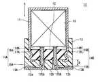
- An electrolytic capacitor 2A shown in FIG. 7includes a capacitor element 10 including an anode foil 21 (see FIG. 2) and a cathode foil 22 (see FIG. 2), and an electrolyte solution (shown) interposed between the anode foil 21 and the cathode foil 22. And a bottomed cylindrical case 11 that accommodates the capacitor element 10 and the electrolytic solution and has an opening. Examples of the material of the case 11 include metals such as aluminum, stainless steel, copper, iron, brass, and alloys thereof.
- the electrolytic capacitor 2 ⁇ / b> Aincludes a sealing member 12 that seals the opening of the case 11 and a mold resin layer 13 that covers the sealing member 12.
- the mold resin layer 13is provided so as to cover the opening of the case 11 together with the main surface disposed on the outside of the case 11 of the sealing member 12.
- the opening of case 11is sealed with sealing member 12 and mold resin layer 13 after accommodating capacitor element 10.
- the vicinity of the opening end of the case 11is drawn to the sealing member 12 side, and the opening end of the case 11 is crimped inward.
- the sealing member 12is fixed to the opening of the case 11, and the case 11 is sealed by the sealing member 12.
- the mold resin layer 13further covers at least a part of the side surface following the opening of the case 11. Thereby, the sealing performance of the electrolytic capacitor can be further enhanced.
- the mold resin layer 13, the case 11, and the sealing member 12may have portions that are not partially bonded.
- the same configuration and materials as those of the first embodimentcan be used.
- the electrolytic capacitor 2Aincludes a pair of leads 14A and 14B that are electrically connected to the anode foil 21 and the cathode foil 22 included in the capacitor element 10 and penetrate the sealing member 12 and the mold resin layer 13, respectively.
- leads 14A and 14BWhen the electrolytic capacitor is mounted on the substrate, the capacitor element 10 and the terminal on the substrate are electrically connected via the leads 14A and 14B.
- the leads 14A and 14Bhave tab portions 16A and 16B connected to the anode foil 21 and the cathode foil 22, respectively, and lead portions 15A and 15B connected to the tab portions 16A and 16B, respectively.
- the lead portions 15A and 15B and the tab portions 16A and 16Bare connected by welding or the like.
- the lead portions 15A and 15Binclude a metal such as iron, copper, nickel, and tin, for example.
- the tab portions 16A and 16Binclude, for example, aluminum.
- the tab portions 16A and 16Bhave rod-like portions 17A and 17B and flat portions 18A and 18B, respectively.
- the rod-like portions 17A and 17B and the flat portions 18A and 18Bmay be electrically connected, or may be integrated.
- a flat partis formed by rolling one end part of a rod-like body, and a tab part in which the flat part and the rod-like part are integrated can be formed by leaving an unrolled region as a rod-like part.
- the rod-like portions 17A and 17Beach include a portion disposed in the sealing member 12.
- the lead portions 15A and 15Bextend from the tip portions of the rod-like portions 17A and 17B, respectively.
- the rod-like portions 17A and 17Bare connected to the capacitor element 10 via flat portions 18A and 18B, respectively. By having the flat portions 18A and 18B, the connection between the leads 14A and 14B and the capacitor element is facilitated.
- the shape of the drawer portions 15A and 15Bis not particularly limited, and may be, for example, a wire shape or a ribbon shape.
- the shape of the rod-shaped portions 17A and 17Bis not particularly limited, and may be a round rod shape (for example, a rod shape having a circular or elliptical cross section) or a square bar shape (for example, a rod shape having a polygonal cross section). Also good.
- the leads 14A and 14Bhave insulating regions covered with the electrical insulating layers 19A and 19B.
- the electrically insulating layers 19A and 19Bare provided between the leads 14A and 14B and the sealing member 12 and the mold resin layer 13.
- the electrical insulating layers 19A and 19Bare provided, the chlorine component contained in the sealing member 12 is dissolved in the electrolytic solution staying in the sealing member 12 or at the boundary between the sealing member 12 and the mold resin layer 13. However, lead corrosion can be suppressed.
- the electrical insulating layers 19 ⁇ / b> A and 19 ⁇ / b> Bare preferably provided so that the leads 14 ⁇ / b> A and 14 ⁇ / b> B do not contact the boundary between the sealing member 12 and the mold resin layer 13.
- the electrical insulating layers 19A and 19Bit is possible to prevent the leads 14A and 14B from coming into contact with the electrolytic solution staying at the boundary between the sealing member 12 and the mold resin layer 13.
- the progress of corrosion of the leads 14A and 14B (particularly, the anode-side lead 14A) when a voltage is applied to the electrolytic capacitor in a state where the leads 14A and 14B are in contact with the electrolytic solutioncan be suppressed.
- the electrical insulating layers 19 ⁇ / b> A and 19 ⁇ / b> Bare provided across the boundary between the sealing member 12 and the mold resin layer 13. In this case, it is possible to further enhance the effect of suppressing the leads 14A and 14B from coming into contact with the electrolytic solution staying at the boundary between the sealing member 12 and the mold resin layer 13.
- the electrical insulating layers 19A and 19Bhave excellent corrosion resistance against an electrolyte or a solvent containing a chlorine component. In this case, the effect of providing the insulating region can be maintained over a long period of time.
- the thickness of the electrical insulating layers 19A and 19Bis, for example, not less than 0.01 mm and not more than 1.00 mm.
- the lead portions 15A and 15Binclude a transition metal
- the end portions of the lead portions 15A and 15B and the rod-like portions 17A and 17Bare melted when the lead portions 15A and 15B are welded to the rod-like portions 17A and 17B.
- the transition metalis exposed on the surface of the joint. Therefore, when the joining portion comes into contact with the electrolytic solution staying at the boundary between the sealing member 12 and the mold resin layer 13, corrosion easily proceeds at the joining portion (particularly, the joining portion on the anode side), and the lead is easily disconnected at the joining portion. . Therefore, as shown in FIG.
- the joint portions between the tab portions 16A and 16B (rod-like portions 17A and 17B) and the lead portions 15A and 15Bare covered with the electrical insulating layers 19A and 19B.
- the insulating regionis preferably provided in a region extending from the rod-like portions 17A and 17B of the leads 14A and 14B to the lead portions 15A and 15B.
- At least a part of the joint portion between the tab portions 16 ⁇ / b> A and 16 ⁇ / b> B (rod-like portions 17 ⁇ / b> A and 17 ⁇ / b> B) and the lead portions 15 ⁇ / b> A and 15 ⁇ / b> Bis formed between the sealing member 12 and the mold resin layer 13.
- the distances t 1a and t 1b in which the insulating regions extend from the boundary between the sealing member 12 and the mold resin layer 13 toward the mold resin layer 13are preferably 10% or more of the thickness T 1 of the mold resin layer 13. . In this case, the sealing performance of the electrolytic capacitor can be further improved.
- the distances t 1a and t 1b between the insulating regionsare such that the electrically insulating layers 19A and 19B are molded resin from the boundary surface between the sealing member 12 and the mold resin layer 13 along the direction perpendicular to the boundary surface. This is the distance extending to the layer 13 side.
- the thickness T 1 of the mold resin layer 13is the thickness in the axial direction of the case 11 (X direction in FIG. 1), and the thickness of the region where the groove portions 13A and 13B of the mold resin layer 13 described later are not provided. It is.
- the distances t 2a and t 2b in which the insulating regions extend from the boundary between the sealing member 12 and the mold resin layer 13 toward the sealing member 12are 10% or more of the thickness T 2 of the sealing member 12. In this case, the sealing performance of the electrolytic capacitor can be further improved.
- the distances t 2a and t 2b between the insulating regionsare such that the electrically insulating layers 19A and 19B are sealed along the direction perpendicular to the boundary surface from the boundary surface between the sealing member 12 and the mold resin layer 13. This is the distance extending to the 12 side.
- the thickness T 2 of the sealing member 12is the thickness in the axial direction of the case 11 (X direction in FIG. 1).
- the insulating regionis provided in both the lead 14A and the lead 14B, but an insulating region may be provided in one of the lead 14A and the lead 14B.
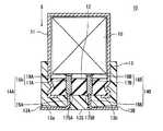
- the electrical insulation layers 19A and 19B shown in FIG. 7are provided, but the electrical insulation layers 29A and 29B shown in FIG. 8 may be provided.
- the electrical insulating layers 29A and 29BBy providing the electrical insulating layers 29A and 29B, the contact with the electrolytic solution can be suppressed over the entire region where the leads 14A and 14B penetrate the sealing member 12 and the mold resin layer 13.
- One end of the electrical insulating layers 29A and 29Bis exposed from the main surface of the sealing member 12 opposite to the mold resin layer 13 side. In this case, the effect of providing the insulating region can be further enhanced.
- the other end portions of the electrical insulating layers 29A and 29Bare exposed from the mounting surface 13S side of the mold resin layer 13. In this case, the effect of providing the insulating region can be further enhanced. However, it is preferable not to provide the electrical insulating layers 29A and 29B in the portion where the leads 14A and 14B are mounted in order to improve mountability.
- the electrical insulating layers 19A, 19B, 29A, and 29Binclude at least one of an insulating resin layer and an insulating ceramic layer.
- an electrical insulation layer having excellent electrical insulation and corrosion resistance against an electrolytic solutiona solvent containing a chlorine component
- the insulating resin layerpreferably includes a cured product of a curable resin composition, a thermoplastic resin, or a composition containing the same.
- curable resinwhat was illustrated as a material which can be used for mold resin layers, such as thermosetting resin, for example can be used.
- the curable resin compositionmay contain a filler, a curing agent and the like in addition to the curable resin.
- thermosetting resinfor example, phenol resin, epoxy resin, melamine resin, urea resin, unsaturated polyester, alkyd resin, polyurethane, thermosetting polyimide and the like can be used.
- the thermosetting resinis preferably a phenol resin, an epoxy resin, or a thermosetting polyimide.
- thermoplastic resinexamples include fluorine resin (for example, polytetrafluoroethylene), polyamideimide, polyimide, polyethylene, polypropylene, polyvinyl chloride, polyvinylidene chloride, polystyrene, polyvinyl acetate, ABS resin, AS resin, acrylic resin, and the like. Can be used. Among them, the thermoplastic resin is preferably a fluororesin, polyamideimide, or polyimide.
- the insulating resin layermay be formed by applying a thermosetting resin composition to a predetermined portion of the lead and then curing it, or by applying a thermoplastic resin (composition) to a predetermined portion of the lead. May be.
- the insulating resin layermay be formed by sticking an insulating resin tape to a predetermined portion of the lead.
- the insulating ceramic layerpreferably contains silica, metal oxide, carbide, boride, and coupling agent.
- the silicainclude natural crystalline silica, natural amorphous silica, synthetic crystalline silica, and synthetic amorphous silica.
- a silicacontains a synthetic amorphous silica.
- the metal oxideinclude an oxide containing aluminum, an oxide containing titanium, and an oxide containing tantalum.
- the carbideincludes, for example, silicon carbide, titanium carbide, boron carbide and the like.
- boridesinclude aluminum diboride and titanium diboride.
- the coupling agentincludes, for example, a silane coupling agent and a titanate coupling agent.
- the insulating ceramic layeris formed, for example, by attaching ceramics to a predetermined portion of the lead by an aerosol deposition method, applying a tape containing ceramics, or applying a paint containing ceramics.
- the electrical insulating layermay be formed before the lead is inserted into the sealing member, or after the lead is inserted into the sealing member.
- FIG. 9 and FIG. 10show examples of the electrolytic capacitor when the electrical insulating layer is formed before the lead is inserted into the sealing member.
- 9 and 10are cross-sectional views of the main part showing the vicinity of the boundary between the sealing member and the mold resin layer in the electrolytic capacitor.
- electrically insulating layers 39A and 39B shown in FIG. 9are provided. Thereafter, the rod-like portions 17A and 17B are inserted into the sealing member 12 so that the joint portions of the lead portions 15A and 15B and the rod-like portions 17A and 17B are located in the holes of the sealing member 12, and then the mold resin layer 13 is formed. To do.
- electrically insulating layers 49A and 49B shown in FIG. 10are provided. Thereafter, the rod-like portions 17A and 17B are inserted into the sealing member 12 so that the joint portions of the lead portions 15A and 15B and the rod-like portions 17A and 17B are located outside the hole of the sealing member 12, and then the mold resin layer 13 is formed. To do.
- 11 and 12show examples of electrolytic capacitors when the electrical insulating layer is formed after the lead is inserted into the sealing member.
- 11 and 12are cross-sectional views of the main part showing the vicinity of the boundary between the sealing member and the mold resin layer in the electrolytic capacitor.
- the rod-like portions 17A and 17Bare inserted into the sealing member 12 so that the joint portions of the lead portions 15A and 15B and the rod-like portions 17A and 17B are positioned in the hole of the sealing member 12. . Thereafter, electrical insulating layers 59A and 59B shown in FIG. 11 are provided, and then a mold resin layer 13 is formed.
- the rod-shaped portions 17A and 17Bare inserted into the sealing member 12 so that the joint portions of the lead portions 15A and 15B and the rod-shaped portions 17A and 17B are located outside the hole of the sealing member 12. . Thereafter, electrical insulating layers 69A and 69B shown in FIG. 12 are provided, and then a mold resin layer 13 is formed.
- the electrical insulating layeris not limited to the electrical insulating layer shown in FIGS.
- the electrical insulating layermay be provided between the lead and the sealing member and the mold resin layer (for example, straddling the boundary between the sealing member and the mold resin layer).
- the electrical insulating layermay be provided only between the lead and the sealing member (region where the lead penetrates the sealing member), or between the lead and the mold resin layer (region where the lead penetrates the mold resin). You may provide only.
- the lead portions 15 ⁇ / b> A and 15 ⁇ / b> Bhave a portion that is drawn out from the mounting surface 13 ⁇ / b> S side of the mold resin layer 13, and the portion is arranged along the mounting surface 13 ⁇ / b> S of the mold resin layer 13.
- elongated grooves 13A and 13B for accommodating portions (leading portions 15A and 15B) drawn out from the molding resin layer 13 of the leads 14A and 14Bare formed on the mounting surface 13S of the molding resin layer 13. It may be provided.
- the lead portions 15A and 15Bcan be stably fixed and arranged near the mounting surface 13S.
- the bottom surfaces 13a and 13b of the groove portions 13A and 13Bare formed so that the lead portions 14A and 14B of the groove portions 13A and 13B are gradually extended from one end portion of the groove portions 13A and 13B to the other end portion. Inclined to increase depth.
- the drawer portions 15A and 15Bare bent so as to be substantially parallel to the mounting surface 13S, a force is applied to the drawer portions 15A and 15B to return to the original shape.
- the bottom surfaces of the groove portions 13A and 13Bare inclined as described above, so that the lead portions 15A and 15B do not excessively jump out of the mounting surface 13S, and the lead portions 15A and 15B are placed in the groove portions 13A and 13B. Can be accommodated.
- the inclination angle of the bottom surfaces of the groove portions 13A and 13B with respect to the mounting surface 13Sis, for example, 3 ° or more and 30 ° or less.
- the bottom surfaces of the groove portions 13A and 13Bare inclined, but the depths of the groove portions 13A and 13B may be constant without inclining the bottom surfaces of the groove portions 13A and 13B.
- sealing member 12As the sealing member 12, the same configuration and materials as those of the first embodiment can be used.
- the capacitor element 10is the same as that of the first embodiment, the description thereof is omitted.
- the conductivity of the electrolytic solutionmay be low.
- the electrolyte contained in the casemay contain a solvent that can dissolve the chlorine component contained in the sealing member. Therefore, even when the amount of the electrolytic solution (solvent) in the case is small, the lead may be corroded. By providing the electrically insulating layer, the effect of suppressing such corrosion of the lead can be obtained.
- the mold resin layeris usually formed in close contact with the sealing member.
- the degree of expansion (linear expansion coefficient) when the temperature risesgreatly differs between the mold resin layer and the sealing member. Therefore, stress concentrates in the vicinity of the boundary between the mold resin layer and the sealing member, thereby causing cracks in the mold resin layer and reducing the sealing performance of the electrolytic capacitor.
- An electrolytic capacitor according to a third embodiment of the present disclosureincludes a capacitor element that includes a pair of electrodes, a case that houses the capacitor element, a sealing member, a mold resin layer that covers the sealing member, a sealing member, and a mold resin layer.
- the casehas an opening.
- the sealing memberseals the opening of the case.
- the pair of leadsare electrically connected to the pair of electrodes, respectively.
- a gapis provided between the sealing member and the mold resin layer.
- the gapis preferably a minute gap formed when the mold resin layer is not in close contact (adhesion) with the sealing member.
- the small gapis advantageous for miniaturization of the electrolytic capacitor.
- the minute gapcan be formed by a method described later.
- the mold resin layerfurther covers at least a part of the side surface following the opening of the case.
- the sealing performance of the electrolytic capacitorcan be further improved.
- the mold resin layeris preferably in close contact with the case in a region facing the case. In this case, the mold resin layer covering the sealing member can be more firmly fixed and provided.
- the electrolytic capacitorhas an electrolytic solution
- a film of a component contained in the electrolytic solutionis formed on the surface (exposed surface) of the sealing member exposed in the gap. That is, it is preferable that at least a part of the exposed surface is covered with a film of a component contained in the electrolytic solution.
- the film of the component contained in the electrolytic solutionis the electrolytic solution accommodated in the case.
- These componentsmay permeate through the sealing member and stay in the gap between the sealing member and the mold resin layer.
- a componentfor example, a solvent contained in the electrolytic solution is relatively easily transmitted through the sealing member. However, it is difficult to penetrate the mold resin layer.
- the component of the electrolyte that has permeated through the sealing membereasily stays in the gap between the sealing member and the mold resin layer. Therefore, a film of the component of the electrolytic solution can be efficiently formed on the exposed surface of the sealing member.
- One of the pair of electrodesis an anode, and the other is a cathode.
- the anodehas a dielectric layer on the surface.
- One of the pair of leadsis an anode lead that is electrically connected to the anode, and the other is a cathode lead that is electrically connected to the cathode.
- a pair of leads penetrating the sealing member and the mold resin layeris exposed in a gap provided between the sealing member and the mold resin layer. Therefore, it is preferable that at least one of the pair of leads has an insulating region covered with an electrical insulating layer. More preferably, the insulating region is provided across at least the gap. That is, it is more preferable that the insulating region is provided so that the lead passes through the gap from the portion that penetrates the sealing member to the portion that penetrates the mold resin layer.
- the insulating regionBy providing the insulating region, even when a film of the component contained in the electrolytic solution is formed in the gap between the sealing member and the mold resin layer (the component contained in the electrolytic solution stays), a pair of leads, Contact with the components of the electrolytic solution is suppressed. If a voltage is applied to the electrolytic capacitor in a state where the pair of leads and the components of the electrolytic solution are in contact with each other, corrosion of the leads (particularly, the anode lead) proceeds. Providing the insulating region suppresses the progress of such corrosion.
- both the pair of leadsare provided with insulating regions.
- the electrical insulating layeris preferably excellent in resistance to electrolyte. In this case, the effect of providing the insulating region can be maintained over a long period of time.
- the electrical insulating layerpreferably includes, for example, at least one of an insulating resin layer and an insulating ceramic layer.
- the electrolytic capacitormay include an electrolytic solution interposed between the pair of electrodes, and the electrolytic solution may be accommodated in the case.
- the electrolytic capacitormay include a solid electrolyte layer that covers at least a part of the surface of the dielectric layer.
- the electrolytic capacitormay include both the electrolytic solution and the solid electrolyte layer.
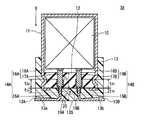
- An electrolytic capacitor 3A shown in FIG. 13includes a capacitor element 10 including an anode foil 21 (see FIG. 2) and a cathode foil 22 (see FIG. 2), and an electrolyte solution (shown) interposed between the anode foil 21 and the cathode foil 22. And a bottomed cylindrical case 11 that accommodates the capacitor element 10 and the electrolytic solution and has an opening. Examples of the material of the case 11 include metals such as aluminum, stainless steel, copper, iron, brass, and alloys thereof.
- the electrolytic capacitor 3 ⁇ / b> Aincludes a sealing member 12 that seals the opening of the case 11 and a mold resin layer 13 that covers the sealing member 12.
- the mold resin layer 13is provided so as to cover the opening of the case 11 together with the main surface disposed on the outside of the case 11 of the sealing member 12.
- the opening of case 11is sealed with sealing member 12 and mold resin layer 13 after accommodating capacitor element 10.
- the vicinity of the opening end of the case 11is drawn to the sealing member 12 side, and the opening end of the case 11 is crimped inward. Thereby, the sealing member 12 is fixed to the opening of the case 11, and the case 11 is sealed by the sealing member 12.
- the sealing performance of the electrolytic capacitor 3Ais further enhanced.
- the mold resin layer 13is not bonded to the sealing member 12 in a region facing the sealing member 12, and a minute gap 20 is formed between the mold resin layer 13 and the sealing member 12.
- a minute gap 20is formed between the mold resin layer 13 and the sealing member 12.
- the mold resin layer 13further covers at least a part of the side surface following the opening of the case 11. Thereby, the sealing performance of the electrolytic capacitor 3A can be further improved.
- the mold resin layer 13is bonded to the case 11 in a region facing the case 11. Thereby, the mold resin layer 13 covering the sealing member 12 can be firmly fixed and provided.
- the mold resin layer 13only needs to be partially bonded to the case 11 in a region facing the case 11, and there may be a portion that is not bonded.
- the same configuration and materials as those of the first embodimentcan be used.
- a predetermined region of the sealing member 12region covered with the mold resin layer 13.
- a release agentmay be applied.
- the release agentfor example, a silicone-based or fluorine-based release agent is used.
- a film (not shown) of a component contained in the electrolytic solutionis formed on the surface (exposed surface) of the sealing member 12 exposed in the gap 20.
- the component of the electrolyte contained in the electrolytic solutionmay be formed so as to cover at least a part of the exposed surface of the sealing member 12 by retaining the component of the electrolytic solution that has passed through the sealing member 12 in the gap 20. it can.
- the electrolytic capacitorincludes a pair of leads 14A and 14B that are electrically connected to the anode foil 21 and the cathode foil 22 included in the capacitor element 10 and penetrate the sealing member 12 and the mold resin layer 13, respectively.
- leads 14A and 14BWhen the electrolytic capacitor is mounted on the substrate, the capacitor element 10 and the terminal on the substrate are electrically connected via the leads 14A and 14B.
- the leads 14A and 14Bhave tab portions 16A and 16B connected to the anode foil 21 and the cathode foil 22, respectively, and lead portions 15A and 15B connected to the tab portions 16A and 16B, respectively.
- the lead portions 15A and 15B and the tab portions 16A and 16Bare connected by welding or the like.
- the lead portions 15A and 15Binclude a metal such as iron, copper, nickel, and tin, for example.
- the tab portions 16A and 16Binclude, for example, aluminum.
- the tab portions 16A and 16Bhave rod-like portions 17A and 17B and flat portions 18A and 18B, respectively.
- the rod-like portions 17A and 17B and the flat portions 18A and 18Bmay be electrically connected, or may be integrated.
- a flat partis formed by rolling one end part of a rod-like body, and a tab part in which the flat part and the rod-like part are integrated can be formed by leaving an unrolled region as a rod-like part.
- the rod-shaped portions 17A and 17Beach include a portion that penetrates the sealing member 12.
- the shape of the rod-shaped portions 17A and 17Bis not particularly limited, and may be a round rod shape (for example, a rod shape having a circular or elliptical cross section) or a square bar shape (for example, a rod shape having a polygonal cross section). Also good.
- the rod-like portions 17A and 17Bare connected to the capacitor element 10 via flat portions 18A and 18B, respectively. By having the flat portions 18A and 18B, the connection between the leads 14A and 14B and the capacitor element is facilitated.
- the lead portions 15A and 15Beach include a portion penetrating the mold resin layer 13.
- the shape of the lead portions 15A and 15Bis not particularly limited, and may be, for example, a wire shape or a ribbon shape.
- the lead portions 15A and 15Bextend from the tip portions of the rod-like portions 17A and 17B, respectively.
- FIG. 14is a cross-sectional view of the main part showing the vicinity of the boundary between the sealing member and the mold resin layer in the electrolytic capacitor.
- the rod-like portions 17A and 17Bare inserted into the holes of the sealing member 12 so that the joint portions of the lead portions 15A and 15B and the rod-like portions 17A and 17B are positioned in the holes of the sealing member 12. .
- the tip portions of the rod-like portions 17A and 17Bare exposed from the sealing member 12 on the mold resin layer 13 side.
- a gap 30is provided between the end portions of the rod-like portions 17 ⁇ / b> A and 17 ⁇ / b> B and the sealing member 12 and the mold resin layer 13.
- the gap 30is formed by the following method, for example.
- the rod-like portions 17A and 17Bare inserted into the holes of the sealing member 12 so that the joint portions of the lead portions 15A and 15B and the rod-like portions 17A and 17B are located in the holes of the sealing member 12. Thereafter, when the mold resin layer 13 is formed, a release agent is applied to the tip portions of the rod-like portions 17A and 17B and a predetermined region of the sealing member 12 (region covered with the mold resin layer 13).
- FIG. 15shows an example of an electrolytic capacitor in the case where a gap is formed in a state where the rod-like portion is inserted into the hole of the sealing member so that the joint portion between the drawer portion and the rod-like portion is located outside the hole of the sealing member. Shown in FIG. 15 is a cross-sectional view of the main part showing the vicinity of the boundary between the sealing member and the mold resin layer in the electrolytic capacitor.
- the rod-like portions 17 ⁇ / b> A and 17 ⁇ / b> Bare inserted into the holes of the sealing member 12 so that the joint portions of the drawer portions 15 ⁇ / b> A and 15 ⁇ / b> B and the rod-like portions 17 ⁇ / b> A and 17 ⁇ / b> B are located outside the hole of the sealing member 12. .
- the tip portions of the rod-like portions 17A and 17Bare exposed from the sealing member 12 on the mold resin layer 13 side.
- a gap 40is provided between the end portions of the rod-like portions 17 ⁇ / b> A and 17 ⁇ / b> B and the sealing member 12 and the mold resin layer 13.
- the gap 40is formed by the following method, for example.
- the rod-like portions 17A and 17Bare inserted into the holes of the sealing member 12 so that the joint portions of the lead portions 15A and 15B and the rod-like portions 17A and 17B are located in the holes of the sealing member 12. Thereafter, when the mold resin layer 13 is formed, a release agent is applied to the tip portions of the rod-like portions 17A and 17B and a predetermined region of the sealing member 12 (region covered with the mold resin layer 13).
- the rod-like portions 17A and 17Bare disposed between the tip portions of the rod-like portions 17A and 17B and the mold resin layer 13.
- a gap that is continuous with the gap formed between the sealing member 12 and the mold resin layer 13may be further formed.
- the leads 14A and 14Bhave insulating regions covered with the electrical insulating layers 19A and 19B.
- the insulating regionis preferably provided across at least the gap 20. That is, it is preferable that the insulating region is provided so that the leads 14A and 14B pass through the gap 20 from the portion that penetrates the sealing member 12 to the portion that penetrates the mold resin layer 13.
- an insulating regionis provided in both the lead 14A and the lead 14B, but an insulating region may be provided in one of the lead 14A and the lead 14B.
- the lead portions 15A and 15Binclude a transition metal
- the end portions of the lead portions 15A and 15B and the rod-like portions 17A and 17Bare melted when the lead portions 15A and 15B are welded to the rod-like portions 17A and 17B.
- the transition metalis exposed on the surface of the joint. Therefore, when the joint portion comes into contact with the component of the electrolytic solution staying in the gap 20, corrosion tends to proceed at the joint portion (particularly, the joint portion on the anode side), and the lead is easily broken at the joint portion. Therefore, as shown in FIG.
- the joint portions between the tab portions 16A and 16B (rod-like portions 17A and 17B) and the lead portions 15A and 15Bare covered with the electrical insulating layers 19A and 19B.
- the insulating regionis preferably provided in a region extending from the rod-like portions 17A and 17B of the leads 14A and 14B to the lead portions 15A and 15B.
- the distances t 1a and t 1b in which the insulating regions extend from the boundary between the mold resin layer 13 and the gap 20 to the mold resin layer 13 sideare preferably 10% or more of the thickness T 1 of the mold resin layer 13. In this case, the effect of providing the insulating region can be further enhanced.
- the distances t 1a and t 1b between the insulating regionsare such that the electrically insulating layers 19A and 19B are molded resin layers along the direction perpendicular to the boundary surface from the boundary surface between the mold resin layer 13 and the gap 20. This is the distance extending to the 13th side.
- the thickness T 1 of the mold resin layer 13is the thickness of the case 11 in the axial direction (X direction in FIG. 16), and the thickness of the region where the groove portions 13A and 13B of the mold resin layer 13 to be described later are not provided. It is.
- the distances t 2a and t 2b in which the insulating region extends from the boundary between the sealing member 12 and the gap 20 to the sealing member 12 sideis preferably 10% or more of the thickness T 2 of the sealing member 12. In this case, the effect of providing the insulating region can be further enhanced.
- the distances t 2a and t 2b between the insulating regionsare such that the electrically insulating layers 19A and 19B are on the sealing member 12 side along the direction perpendicular to the boundary surface from the boundary surface between the sealing member 12 and the gap 20. It is the distance extended to.
- the thickness T 2 of the sealing member 12is the thickness in the axial direction of the case 11 (X direction in FIG. 16).
- the electrical insulating layers 19A and 19Binclude an insulating resin layer and / or an insulating ceramic layer excellent in electrolytic solution resistance.
- the thickness of the electrical insulating layers 19A and 19Bmay be, for example, 0.01 mm or more and 1.00 mm or less.
- the insulating resin layer and the insulating ceramic layerAs the insulating resin layer and the insulating ceramic layer, the same configuration and materials as those of the second embodiment can be used.
- the insulating ceramic layeris formed, for example, by attaching ceramics to a predetermined portion of the lead by an aerosol deposition method, applying a tape containing ceramics, or applying a paint containing ceramics. .
- the lead portions 15 ⁇ / b> A and 15 ⁇ / b> Bhave portions drawn out from the mounting surface 13 ⁇ / b> S side of the mold resin layer 13.
- the portionis arranged along the mounting surface 13 ⁇ / b> S of the mold resin layer 13.
- elongated grooves 13A and 13B for accommodating the portions of the leads 14A and 14B drawn from the mold resin layer 13 to the outsideare provided on the mounting surface 13S of the mold resin layer 13, as shown in FIG. 13, elongated grooves 13A and 13B for accommodating the portions of the leads 14A and 14B drawn from the mold resin layer 13 to the outside are provided. It may be provided.
- the lead portions 15A and 15Bcan be stably fixed and arranged near the mounting surface 13S.
- the bottom surfaces 13a and 13b of the groove portions 13A and 13Bare formed so that the lead portions 14A and 14B of the groove portions 13A and 13B are gradually extended from one end portion of the groove portions 13A and 13B to the other end portion. Inclined to increase depth.
- a forceis applied to the drawer portions 15A and 15B to return to the original shape.
- the lead portions 15A and 15Bdo not excessively jump out of the mounting surface 13S, and the lead portions 15A and 15B are moved to the groove portions 13A and 13B.
- the inclination angles of the bottom surfaces 13a and 13b of the groove portions 13A and 13B with respect to the mounting surface 13Sare, for example, 3 ° or more and 30 ° or less.
- the bottom surfaces of the groove portions 13A and 13Bare inclined, but the depths of the groove portions 13A and 13B may be constant without inclining the bottom surfaces of the groove portions 13A and 13B.
- sealing member 12As the sealing member 12, the same configuration and materials as those of the first embodiment can be used.
- Capacitor element 10may include an electrolytic solution and a solid electrolyte layer.
- the present disclosureis useful in an electrolytic capacitor including an electrolytic solution in a case and including a sealing member and a mold resin layer.
- Electrolytic capacitor 10Capacitor element 11: Case 12: Sealing member 13: Mold resin layer 13S: Mounting surface 13A, 13B: Groove 13a, 13b: Bottom surface 14A, 14B: Lead 15A, 15B: Drawer portion 16A, 16B: Tab portion 17A, 17B: Rod-like portion 18A, 18B: Flat portion 19A, 19B, 29A, 29B, 39A, 39B, 49A, 49B, 59A, 59B, 69A, 69B : Electrical insulating layers 20, 30, 40: Crevice 21: Anode, anode foil 22: Cathode, cathode foil 23: Separator 24: Winding tape 175A, 175B: In-lead connection portion
Landscapes
- Engineering & Computer Science (AREA)
- Power Engineering (AREA)
- Microelectronics & Electronic Packaging (AREA)
- Electric Double-Layer Capacitors Or The Like (AREA)
- Fixed Capacitors And Capacitor Manufacturing Machines (AREA)
Abstract
Description
Translated fromJapanese本開示は、封口部材を覆うモールド樹脂層を備える電解コンデンサに関する。The present disclosure relates to an electrolytic capacitor including a mold resin layer that covers a sealing member.
電解コンデンサは、一対の電極を含むコンデンサ素子と、一対の電極の間に介在する電解液と、コンデンサ素子および電解液を収容し、開口を有するケースと、ケースの開口を封止する封口部材と、一対の電極にそれぞれ電気的に接続され、かつ、封口部材を貫通する一対のリードとを備える。各リードは、例えばアルミニウムを主成分とするタブ部と、タブ部の一端部に接続された引き出し部とを具備する。タブ部は、ケース内で電極に接続され、引き出し部は、ケース外に引き出される。The electrolytic capacitor includes a capacitor element including a pair of electrodes, an electrolytic solution interposed between the pair of electrodes, a case containing the capacitor element and the electrolytic solution and having an opening, and a sealing member for sealing the opening of the case And a pair of leads electrically connected to the pair of electrodes and penetrating the sealing member. Each lead includes, for example, a tab portion mainly composed of aluminum, and a lead portion connected to one end portion of the tab portion. The tab portion is connected to the electrode within the case, and the lead portion is pulled out of the case.
封口部材は、高温環境下で酸化により劣化することがあり、封口部材が劣化すると、電解コンデンサの封止性が低下する。また、電解液成分が封口部材を透過し、蒸散して、徐々に減少する傾向が見られる。そこで、ケース内の密閉性を高めるために、ケースの開口側を臨む封口部材の外面をモールド樹脂層で覆うことが提案されている(特許文献1)。モールド樹脂層を設けることで、電解液成分のケース外への蒸散が抑制される。The sealing member may be deteriorated by oxidation in a high temperature environment. When the sealing member is deteriorated, the sealing performance of the electrolytic capacitor is lowered. Moreover, the electrolyte component permeates through the sealing member, evaporates, and a tendency to gradually decrease is seen. Then, in order to improve the airtightness in a case, covering the outer surface of the sealing member which faces the opening side of a case with a mold resin layer is proposed (patent document 1). By providing the mold resin layer, evaporation of the electrolyte component to the outside of the case is suppressed.
本開示の第1の局面に係る電解コンデンサは、一対の電極を含むコンデンサ素子と、一対の電極の間に介在する電解液と、コンデンサ素子および電解液を収容するケースと、封口部材と、封口部材を貫通する一対のリードと、モールド樹脂層と、を備える。ケースは、開口を有する。封口部材は、ケースの開口を封止する。一対のリードは、一対の電極にそれぞれ電気的に接続される。モールド樹脂層は、開口側を臨む封口部材の外面の少なくとも一部を覆う。一対のリードの少なくとも一方が、タブ部と、引き出し部と、を有する。タブ部は、電極に接続されている。引き出し部は、タブ部の一端部に接続されている。タブ部の一端部が、封口部材の外面から突出している。An electrolytic capacitor according to a first aspect of the present disclosure includes a capacitor element including a pair of electrodes, an electrolytic solution interposed between the pair of electrodes, a case containing the capacitor element and the electrolytic solution, a sealing member, and a sealing member A pair of leads penetrating the member and a mold resin layer are provided. The case has an opening. The sealing member seals the opening of the case. The pair of leads are electrically connected to the pair of electrodes, respectively. The mold resin layer covers at least a part of the outer surface of the sealing member facing the opening side. At least one of the pair of leads has a tab portion and a lead portion. The tab portion is connected to the electrode. The drawer portion is connected to one end portion of the tab portion. One end of the tab portion protrudes from the outer surface of the sealing member.
本開示によれば、ケースの開口側を臨む封口部材の外面の少なくとも一部を覆うモールド樹脂層を備える電解コンデンサにおいて、リードの腐食を抑制することができる。According to the present disclosure, it is possible to suppress lead corrosion in an electrolytic capacitor including a molded resin layer that covers at least a part of the outer surface of the sealing member facing the opening side of the case.
また、本開示の第2の局面に係る電解コンデンサは、一対の電極を含むコンデンサ素子と、一対の電極の間に介在する電解液と、コンデンサ素子および電解液を収容するケースと、封口部材と、封口部材を覆うモールド樹脂層と、封口部材およびモールド樹脂層を貫通する一対のリードと、を備える。ケースは、開口を有する。封口部材は、ケースの開口を封止する。一対のリードは、一対の電極にそれぞれ電気的に接続する。一対のリードの少なくとも一方が、電気的絶縁層で覆われた絶縁領域を有する。電気的絶縁層は、一対のリードの少なくとも一方と、封口部材およびモールド樹脂層の少なくとも一方との間に設けられている。In addition, an electrolytic capacitor according to a second aspect of the present disclosure includes a capacitor element including a pair of electrodes, an electrolytic solution interposed between the pair of electrodes, a case containing the capacitor element and the electrolytic solution, a sealing member, A mold resin layer covering the sealing member, and a pair of leads penetrating the sealing member and the mold resin layer. The case has an opening. The sealing member seals the opening of the case. The pair of leads are electrically connected to the pair of electrodes, respectively. At least one of the pair of leads has an insulating region covered with an electrically insulating layer. The electrical insulating layer is provided between at least one of the pair of leads and at least one of the sealing member and the mold resin layer.
本開示によれば、封口部材を覆うモールド樹脂層を有する電解コンデンサのリードの腐食を抑制することができる。According to the present disclosure, corrosion of the lead of the electrolytic capacitor having the mold resin layer covering the sealing member can be suppressed.
また、本開示の第3の局面に係る電解コンデンサは、一対の電極を含むコンデンサ素子と、コンデンサ素子を収容するケースと、封口部材と、封口部材を覆うモールド樹脂層と、封口部材およびモールド樹脂層を貫通する一対のリードと、を備える。ケースは、開口を有する。封口部材は、ケースの開口を封止する。一対のリードは、一対の電極にそれぞれ電気的に接続する。封口部材とモールド樹脂層との間に、隙間が設けられている。An electrolytic capacitor according to a third aspect of the present disclosure includes a capacitor element including a pair of electrodes, a case that houses the capacitor element, a sealing member, a mold resin layer that covers the sealing member, a sealing member, and a mold resin. A pair of leads penetrating the layer. The case has an opening. The sealing member seals the opening of the case. The pair of leads are electrically connected to the pair of electrodes, respectively. A gap is provided between the sealing member and the mold resin layer.
本開示によれば、モールド樹脂層にクラックが発生することによる電解コンデンサの封止性の低下を抑制することができる。According to the present disclosure, it is possible to suppress a decrease in the sealing performance of the electrolytic capacitor due to the occurrence of cracks in the mold resin layer.
本開示の実施の形態の説明に先立ち、従来技術における問題点を簡単に説明する。一対のリードは、封口部材およびモールド樹脂層を貫通し、モールド樹脂層の実装面の側から引き出されている。電解液(例えば溶媒)は、ゴム成分を含む封口部材を比較的透過し易いが、モールド樹脂層を透過しにくい。そのため、封口部材の外面をモールド樹脂層で覆うと、封口部材の内部や、封口部材とモールド樹脂層との境界に、電解液が滞留することがある。このような場合、封口部材に含まれる塩素成分(塩素を含む成分)が電解液に溶け出し易くなる。リードが塩素成分を含む電解液に接触すると、リードの腐食が進行するおそれがある。Prior to the description of the embodiment of the present disclosure, the problems in the prior art will be briefly described. The pair of leads penetrates the sealing member and the mold resin layer, and is drawn from the mounting surface side of the mold resin layer. The electrolytic solution (for example, solvent) is relatively easy to permeate the sealing member containing the rubber component, but hardly permeates the mold resin layer. Therefore, when the outer surface of the sealing member is covered with the mold resin layer, the electrolytic solution may stay inside the sealing member or at the boundary between the sealing member and the mold resin layer. In such a case, the chlorine component (component containing chlorine) contained in the sealing member is easily dissolved in the electrolytic solution. When the lead comes into contact with the electrolytic solution containing a chlorine component, the lead may be corroded.
より具体的に、図5、6を参照しながら、本開示の参考形態に係る電解コンデンサの一例の構造について説明する。More specifically, an exemplary structure of an electrolytic capacitor according to a reference embodiment of the present disclosure will be described with reference to FIGS.
電解コンデンサ1Dは、コンデンサ素子10と、電解液(図示しない)と、コンデンサ素子10および電解液を収容するケース11とを備える。ケース11の開口は、封口部材12により封止されている。ケース11の開口を臨む封口部材12の外面(以下、単に、封口部材12の外面とも称する。)は、モールド樹脂層13で覆われている。コンデンサ素子10が具備する一対の電極には、それぞれリード14A,14Bが接続されている。The
リード14A,14Bは、それぞれ一方および他方の電極に接続されたタブ部16A,16Bと、タブ部16A,16Bにそれぞれ接続された引き出し部15A,15Bを有する。タブ部16A,16Bと引き出し部15A,15Bとの接続部を、以下、リード内接続部175A,175Bとも称する。The
一方の電極は陽極であり、他方の電極は陰極である。陽極は、表面に誘電体層を有する。電解コンデンサは、誘電体層の表面の少なくとも一部を被覆する固体電解質層を具備してもよい。一方のリードは、陽極に接続された陽極リードであり、他方のリードは、陰極に接続された陰極リードである。One electrode is an anode and the other electrode is a cathode. The anode has a dielectric layer on the surface. The electrolytic capacitor may include a solid electrolyte layer that covers at least part of the surface of the dielectric layer. One lead is an anode lead connected to the anode, and the other lead is a cathode lead connected to the cathode.
図示例では、タブ部16A,16Bは、それぞれ棒状部17A,17Bと、扁平部18A,18Bを有する。扁平部18Aおよび18Bは、それぞれ陽極および陰極に接続されている。棒状部17A,17Bは、それぞれ引き出し部15A,15Bに接続されている。引き出し部15A,15Bの少なくとも一部は、モールド樹脂層13の実装面13Sから外部に引き出され、実装面13Sに設けられた溝部13A,13Bに収容されている。溝部13A,13Bの底面13a,13bは、所定の傾斜を有することが好ましい。In the illustrated example, the
棒状部17A,17Bの一端部(以下、先端部とも称する。)は、封口部材12に設けられた貫通孔内に位置している。封口部材12とモールド樹脂層13との境界付近には、電解液成分が滞留しやすい。棒状部17A,17Bの先端部が封口部材12の貫通孔内に位置する場合、封口部材12とモールド樹脂層13との境界付近に滞留する電解液成分は、リード内接続部175A,175Bおよび引き出し部15A,15Bに接触し易くなる。このとき、滞留する電解液成分により、リード内接続部175A,175Bおよび引き出し部15A,15Bが腐食する。また、封口部材12とモールド樹脂層13との境界の広い範囲に電解液が進入し、一対のリード14A,14Bのリード内接続部175A,175B間および/または引き出し部15A,15B間に電解液成分が滞留すると、当該リード間に電圧が印加されたときに、リード内接続部175A,175Bおよび/または引き出し部15A,15B(特に陽極リード側)の腐食が促進される。さらに、図6に示すように、棒状部17A,17Bの先端部が、封口部材の貫通孔内に位置する場合、リード14A,14Bとモールド樹脂層13との間に隙間が生じやすい。このような隙間には電解液成分が滞留しやすく、リード内接続部175A,175Bおよび/または引き出し部15A,15Bの腐食が促進される。One end portions (hereinafter, also referred to as tip portions) of the rod-
(第1実施形態)
本開示の第1実施形態に係る電解コンデンサは、一対の電極を含むコンデンサ素子と、一対の電極の間に介在する電解液と、コンデンサ素子および電解液を収容するケースと、封口部材と、封口部材を貫通する一対のリードと、モールド樹脂層を備える。封口部材は、ケースの開口を封止する。一対のリードは、一対の電極にそれぞれ電気的に接続される。モールド樹脂層は、封口部材の外面の少なくとも一部を覆う。一対のリードの少なくとも一方が、タブ部と、引き出し部とを有する。タブ部は、電極に接続されている。引き出し部は、タブ部の先端部に接続されている。タブ部の先端部が、封口部材の外面から突出している。これにより、滞留する電解液成分が、棒状部の先端部と引き出し部との接続部に接触することが抑制される。よって、リードの断線のような不具合が生じにくくなる。(First embodiment)
An electrolytic capacitor according to a first embodiment of the present disclosure includes a capacitor element including a pair of electrodes, an electrolytic solution interposed between the pair of electrodes, a case containing the capacitor element and the electrolytic solution, a sealing member, and a sealing member A pair of leads penetrating the member and a mold resin layer are provided. The sealing member seals the opening of the case. The pair of leads are electrically connected to the pair of electrodes, respectively. The mold resin layer covers at least a part of the outer surface of the sealing member. At least one of the pair of leads has a tab portion and a lead portion. The tab portion is connected to the electrode. The drawer portion is connected to the tip portion of the tab portion. The tip part of the tab part protrudes from the outer surface of the sealing member. Thereby, it is suppressed that the electrolyte solution component which stays contacts the connection part of the front-end | tip part of a rod-shaped part, and a drawer | drawing-out part. Therefore, problems such as lead disconnection are less likely to occur.
リードの中でも、タブ部(もしくは棒状部と扁平部)は、元々ケース内に収容される部位であるため、電解液との接触による腐食を生じにくい材質(弁作用金属など)で形成されている。例えば、タブ部は、酸化被膜で覆われているため、腐食を生じにくい。一方、タブ部と引き出し部との接続部(リード内接続部)およびこれに続く引き出し部は、例えば、CP線、Cu線などの腐食しやすい材質(Fe、Cuなどの遷移金属)を含む。タブ部の引き出し部側の端部(もしくは棒状部の先端部)を封口部材から突出させることで、リード内接続部およびこれに続く引き出し部を、モールド樹脂層と封口部材との境界から離間させることができる。これにより、電解液成分とリード内接続部および引き出し部との接触が抑制される。Among the leads, the tab portion (or the rod-like portion and the flat portion) is originally a part accommodated in the case, and is therefore formed of a material (valve action metal or the like) that is unlikely to cause corrosion due to contact with the electrolyte. . For example, since the tab portion is covered with an oxide film, corrosion hardly occurs. On the other hand, the connection part (in-lead connection part) between the tab part and the lead part and the lead part subsequent thereto include, for example, a corrosive material (transition metal such as Fe or Cu) such as CP wire or Cu wire. By projecting the end of the tab portion on the lead portion side (or the tip of the rod-like portion) from the sealing member, the in-lead connection portion and the subsequent lead portion are separated from the boundary between the mold resin layer and the sealing member. be able to. As a result, contact between the electrolytic solution component and the in-lead connecting portion and the lead portion is suppressed.
一対のリードの双方が、滞留する電解液成分と接触した状態で、電圧が印加されると、リード成分が電気分解され、リードの腐食が加速する。よって、一対のリードの少なくとも一方と電解液成分との接触を抑制すれば、リードの腐食は抑制される。陽極リードと陰極リードの中では、陽極リードの腐食が進行しやすいため、少なくとも陽極リードの引き出し側の端部(もしくは棒状部の先端部)を、封口部材の外面から突出させることが好ましい。ただし、リードの腐食を抑制する効果を高めるためには、一対のリードの双方と電解液成分との接触を抑制することが望ましい。When a voltage is applied while both the pair of leads are in contact with the staying electrolyte component, the lead component is electrolyzed and lead corrosion is accelerated. Therefore, if the contact between at least one of the pair of leads and the electrolytic solution component is suppressed, corrosion of the lead is suppressed. In the anode lead and the cathode lead, the corrosion of the anode lead is likely to proceed. Therefore, it is preferable that at least the end portion (or the tip end portion of the rod-like portion) of the anode lead protrudes from the outer surface of the sealing member. However, in order to increase the effect of suppressing lead corrosion, it is desirable to suppress contact between both the pair of leads and the electrolyte component.
リード内接続部は、モールド樹脂層に埋設されていてもよい。これにより、モールド樹脂層とリード内接続部との接着界面が形成される。接着界面には、滞留する電解液成分が侵入しにくいため、リードの腐食を抑制する効果が高められる。なお、リード内接続部は、通常、タブ部と引き出し部との溶接痕を有する。溶接痕の少なくとも一部がモールド樹脂層で覆われていれば、それに応じた腐食の抑制効果を得ることができる。The in-lead connection portion may be embedded in the mold resin layer. As a result, an adhesive interface between the mold resin layer and the in-lead connecting portion is formed. Since the staying electrolyte component hardly enters the adhesion interface, the effect of suppressing lead corrosion is enhanced. In addition, the connection part in a lead has a welding trace of a tab part and a drawer | drawing-out part normally. If at least a part of the welding mark is covered with the mold resin layer, the corrosion inhibiting effect corresponding to that can be obtained.
タブ部の引き出し部側の端部は、モールド樹脂層で覆われていない露出部を有してもよい。露出部は、モールド樹脂層とリードとの接着界面を形成しないため、毛細管現象による露出部への電解液成分の這い上がりは生じない。露出部は、常時、外気に晒されるため、電解液成分で濡れた状態になりにくく、乾燥しやすくなる。よって、リードが電解液成分に接触することが抑制される。The end of the tab portion on the drawer portion side may have an exposed portion that is not covered with the mold resin layer. Since the exposed portion does not form an adhesive interface between the mold resin layer and the lead, the electrolyte component does not creep up to the exposed portion due to capillary action. Since the exposed portion is always exposed to the outside air, the exposed portion is not easily wetted with the electrolyte component and is easily dried. Therefore, it is suppressed that a lead contacts an electrolyte solution component.
封口部材の外面から突出するタブ部の全体を、モールド樹脂層で覆わずに、露出させてもよい。この場合、リードが通過する貫通孔の周囲には、貫通孔を囲むように、モールド樹脂層を有さない領域が形成される。このとき、封口部材から突出するタブ部の周囲には、モールド樹脂層と封口部材との境界が形成されず、その部分が外部に露出している。よって、封口部材から突出するタブ部の周囲における電解液成分の滞留がさらに抑制される。The entire tab portion protruding from the outer surface of the sealing member may be exposed without being covered with the mold resin layer. In this case, a region having no mold resin layer is formed around the through hole through which the lead passes so as to surround the through hole. At this time, the boundary between the mold resin layer and the sealing member is not formed around the tab portion protruding from the sealing member, and the portion is exposed to the outside. Therefore, the retention of the electrolyte component around the tab portion protruding from the sealing member is further suppressed.
一方、タブ部の引き出し部側の端部は、溶接痕の全体がモールド樹脂層で覆われるように、モールド樹脂層に埋設してもよい。このとき、タブ部の引き出し部側の端部に続く引き出し部の一部も一緒にモールド樹脂層に埋設してもよい。On the other hand, the end of the tab portion on the drawer portion side may be embedded in the mold resin layer so that the entire welding trace is covered with the mold resin layer. At this time, a part of the drawer part that follows the end part of the tab part on the drawer part side may be embedded together in the mold resin layer.
タブ部は、タブ部を構成する金属の酸化被膜で覆われていることが好ましい。これにより、タブ部と電解液成分との接触による腐食が生じにくくなる。例えば、タブ部がアルミニウムのような弁作用金属を含む場合、タブ部を陽極酸化して、タブ部に酸化被膜を形成することができる。酸化被膜は、陽極リードだけに形成すれば十分であるが、陰極リードに酸化被膜を形成してもよい。The tab portion is preferably covered with a metal oxide film constituting the tab portion. Thereby, the corrosion by contact with a tab part and electrolyte solution component becomes difficult to occur. For example, when the tab portion includes a valve action metal such as aluminum, the tab portion can be anodized to form an oxide film on the tab portion. It is sufficient to form the oxide film only on the anode lead, but an oxide film may be formed on the cathode lead.
引き出し部は、柔軟な線状部材であることが好ましい。線状部材は、芯材と、芯材の表面を被覆するメッキ層とを具備することが好ましい。芯材は、例えば、導電性に優れるCuや、鋼もしくはFeなどを主成分とすることが好ましい。メッキ層は、低融点金属で形成されていることが好ましい。引き出し部が、低融点金属のメッキ層を具備することで、引き出し部を所定の被接続電極に接続することが容易になる。具体的には、CP線、Cu線などを引き出し部に用いることができる。CP線とは、芯材が鋼もしくはFeなどで形成され、メッキ層がSn、Cuなどで形成される線状部材である。Cu線とは、芯材がCuで形成され、メッキ層がSnなどで形成される線状部材である。The drawer part is preferably a flexible linear member. The linear member preferably includes a core material and a plating layer covering the surface of the core material. The core material preferably contains, for example, Cu having excellent conductivity, steel, Fe, or the like as a main component. The plating layer is preferably formed of a low melting point metal. Since the lead portion includes the low melting point metal plating layer, it becomes easy to connect the lead portion to a predetermined connected electrode. Specifically, a CP line, a Cu line, or the like can be used for the lead portion. The CP wire is a linear member in which a core material is formed of steel or Fe and a plating layer is formed of Sn, Cu, or the like. The Cu wire is a linear member in which a core material is formed of Cu and a plating layer is formed of Sn or the like.
引き出し部に遷移金属が含まれる場合、引き出し部からは、遷移金属が電解液成分に溶出しやすい。これに対し、タブ部の引き出し部側の端部を、封口部材の外面から突出させることで、引き出し部の腐食が顕著に抑制される。When a transition metal is contained in the lead portion, the transition metal is likely to elute into the electrolyte component from the lead portion. In contrast, by causing the end of the tab portion on the drawer portion side to protrude from the outer surface of the sealing member, corrosion of the drawer portion is significantly suppressed.
モールド樹脂層で覆われている封口部材の外面からは、電解液成分の蒸散が抑制される。よって、モールド樹脂層は、封口部材の外面の少なくとも一部を覆っていればよい。既に述べたように、封口部材の外面のうち、リードを通過させるための貫通孔の周囲には、貫通孔を囲むように、モールド樹脂層を有さない領域を設けてもよい。ただし、封口部材の外面のうち、貫通孔の周囲以外の領域は、モールド樹脂層で覆われていることが好ましい。このとき、封口部材の外面の50%以上の面積がモールド樹脂層で覆われていることが好ましい。封口部材の外面の全領域(100%)がモールド樹脂層で覆われていてもよい。From the outer surface of the sealing member covered with the mold resin layer, evaporation of the electrolyte component is suppressed. Therefore, the mold resin layer only needs to cover at least a part of the outer surface of the sealing member. As already described, an area having no mold resin layer may be provided around the through hole for allowing the lead to pass through on the outer surface of the sealing member. However, it is preferable that a region other than the periphery of the through hole in the outer surface of the sealing member is covered with the mold resin layer. At this time, it is preferable that an area of 50% or more of the outer surface of the sealing member is covered with the mold resin layer. The entire area (100%) of the outer surface of the sealing member may be covered with the mold resin layer.
モールド樹脂層は、封口部材の外面に加え、ケースの開口に続く側面の少なくとも一部を覆っていることが好ましい。これにより、ケース内の密閉性を更に高めることができる。モールド樹脂層は、ケースと対向する領域において、ケースに密着していることが好ましい。これにより、モールド樹脂層をより強固に封口部材に固定することができる。It is preferable that the mold resin layer covers at least a part of the side surface following the opening of the case in addition to the outer surface of the sealing member. Thereby, the airtightness in a case can further be improved. The mold resin layer is preferably in close contact with the case in a region facing the case. Thereby, a mold resin layer can be fixed to a sealing member more firmly.
以下、本開示の第1実施形態に係る電解コンデンサについて、図面を参照しながら具体的に説明するが、本開示は、これに限定されるものではない。Hereinafter, the electrolytic capacitor according to the first embodiment of the present disclosure will be specifically described with reference to the drawings, but the present disclosure is not limited thereto.
図1に示す電解コンデンサ1Aは、コンデンサ素子10、電解液(図示しない)およびこれら収容するとともに開口を有するケース11を備える。ケース11は、例えば有底円筒形である。ケース11の開口は、封口部材12で封止されている。ケース11の開口側を臨む封口部材12の外面は、その全体がモールド樹脂層13で覆われている。モールド樹脂層13は、封口部材12の外面とともにケース11の開口を覆うように設けられ、更に、ケース11の開口に続く側面の少なくとも一部を覆っている。An
ケース11の開口は、コンデンサ素子10を収容した後、封口部材12およびモールド樹脂層13で封止される。ケース11の開口端部は、封口部材12側に絞り加工され、内側にかしめ加工されている。これにより、封口部材12がケース11の開口部に固定され、ケース11は封口部材12により密閉される。モールド樹脂層13は、ケース11と対向する領域において、ケース11に部分的に接着していればよく、接着していない箇所があってもよい。The opening of the
モールド樹脂層13は、硬化性樹脂組成物の硬化物を含むことが好ましい。硬化性樹脂組成物は、硬化性樹脂に加え、フィラー、硬化剤、重合開始剤、および/または触媒などを含んでいてもよい。硬化性樹脂としては、光硬化性樹脂や熱硬化性樹脂が例示される。硬化剤、重合開始剤、触媒などは、硬化性樹脂の種類に応じて適宜選択される。The
硬化性樹脂としては、例えば、熱の作用により硬化または重合する化合物(例えば、モノマー、オリゴマー、プレポリマーなど)が使用される。このような化合物(または硬化性樹脂)としては、例えば、エポキシ樹脂、フェノール樹脂、ユリア樹脂、ポリイミド、ポリアミドイミド、ポリウレタン、ジアリルフタレート、不飽和ポリエステルなどが挙げられる。硬化性樹脂組成物は、複数の硬化性樹脂を含んでもよい。As the curable resin, for example, a compound that is cured or polymerized by the action of heat (for example, a monomer, an oligomer, a prepolymer, or the like) is used. Examples of such a compound (or curable resin) include epoxy resin, phenol resin, urea resin, polyimide, polyamideimide, polyurethane, diallyl phthalate, and unsaturated polyester. The curable resin composition may include a plurality of curable resins.
フィラーとしては、例えば、絶縁性の粒子(無機系、有機系)および/または繊維などが好ましい。フィラーを構成する絶縁性材料としては、例えば、シリカ、アルミナなどの絶縁性の化合物(酸化物など)、ガラス、鉱物材料(タルク、マイカ、クレーなど)などが挙げられる。モールド樹脂層は、これらのフィラーを一種含んでもよく、二種以上組み合わせて含んでもよい。モールド樹脂層中のフィラーの含有割合は、例えば、10質量%以上、90質量%以下である。As the filler, for example, insulating particles (inorganic or organic) and / or fibers are preferable. Examples of the insulating material constituting the filler include insulating compounds (such as oxide) such as silica and alumina, glass, mineral materials (such as talc, mica, and clay). The mold resin layer may contain one kind of these fillers, or may contain two or more kinds in combination. The content rate of the filler in a mold resin layer is 10 mass% or more and 90 mass% or less, for example.
モールド樹脂層13は、熱可塑性樹脂もしくはこれを含む組成物を含んでいてもよい。熱可塑性樹脂としては、例えば、ポリフェニレンサルファイド(PPS)、ポリブチレンテレフタレート(PBT)などを用いることができる。The
モールド樹脂層13は、射出成形、インサート成形、圧縮成形などの成形技術を用いて形成することができる。モールド樹脂層13は、例えば、所定の金型を用いて、硬化性樹脂組成物または熱可塑性樹脂(組成物)を封口部材12の外面とともにケース11の開口を覆うように、金型内の所定箇所に充填して形成することができる。The
図2に示すコンデンサ素子10は、陽極21と陰極22とを、これらの間にセパレータ23を介在させて捲回することにより形成されている。陽極21および陰極22には、それぞれ陽極リード14Aおよび陰極リード14Bが電気的に接続されている。各リードは、封口部材12を貫通して外部に引き出されている。The
陽極リード14Aおよび陰極リード14Bは、陽極21および陰極22にそれぞれ接続されたタブ部16A,16Bと、タブ部16A,16Bにそれぞれ接続された引き出し部15A,15Bとを有する。タブ部16A,16Bは、例えば、アルミニウムを含む。引き出し部15A,15Bは、例えば、鉄、銅、ニッケル、錫などの金属を含むCP線、Cu線などである。電解コンデンサ1Aが、基板に実装される際には、引き出し部15A,15Bを介して、基板上の被接続電極とコンデンサ素子10のリード14A,14Bとが電気的に接続される。The anode lead 14A and the
タブ部16A,16Bは、それぞれ棒状部17A,17Bと扁平部18A,18Bとを有する。棒状部17A,17Bと扁平部18A,18Bは、それぞれ互いに電気的に接続されていればよく、一体でもよい。例えば、棒状体の一部を圧延することで、扁平部が形成される。圧延されない領域は、棒状部として残る。これにより、扁平部と棒状部とが一体化されたタブ部16A,16Bを形成することができる。The
棒状部17A,17Bは、それぞれ封口部材12を貫通している。棒状部17A,17Bの形状は、特に制限されず、丸棒状(例えば、断面が円形や楕円形である棒状)でもよく、角棒状(例えば、断面が多角形である棒状)でもよい。棒状部17A,17Bは、それぞれ扁平部18A,18Bを介して、コンデンサ素子10に接続されている。扁平部18A,18Bを有することで、リード14A,14Bと陽極、陰極との接続が容易になる。The rod-shaped
引き出し部15A,15Bは、棒状部17A,17Bの先端部に溶接などにより接続され、引き出し部15A,15Bと棒状部との境界にリード内接続部175A,175Bを形成している。引き出し部15A,15Bの少なくとも一部は、それぞれモールド樹脂層13を通過して外部に引き出されている。引き出し部15A,15Bの形状は、特に制限されず、例えば、ワイヤ状でもよく、リボン状でもよい。The
棒状部17A,17Bの先端部は、封口部材12の外面から突出している。棒状部17A,17Bの最先端部に対応するリード内接続部175A,175Bもしくは溶接痕の最も引き出し部側の部位と、封口部材12の外面との距離Dは、引き出し部15A,15Bもしくはリード内接続部175A,175Bと電解液成分との接触を抑制する観点から大きいほど好ましい。距離Dは、モールド樹脂層13の最大厚さTの5%以上が好ましい。このとき、モールド樹脂層13の実装面13Sから、棒状部17A,17Bの先端部が突出しないことが望ましい。ここで、モールド樹脂層13の最大厚さTとは、モールド樹脂層13の実装面13Sと封口部材12の外面との間の鉛直距離の最大値である。鉛直距離とは、封口部材12の外面の法線方向における距離をいう。The tip portions of the rod-
上記構成においては、リード内接続部175A,175Bがモールド樹脂層13に埋設されている。棒状部17A,17Bの先端部は全体的にモールド樹脂層13で覆われ、モールド樹脂層13と棒状部17A,17Bの先端部との接着界面が十分に大きな面積を持って形成される。このような接着界面により、リード内接続部175A,175Bもしくは引き出し部15A,15Bと、電解液成分との接触が顕著に抑制される。In the above configuration, the in-
図1に示すように、モールド樹脂層13の実装面13Sには、細長形状の溝部13A,13Bが設けられている。引き出し部15A,15Bは、実装面13Sから外部へ引き出された部分を有する。当該部分は、溝部13A,13Bに収容されることで、実装面13S付近に配置される。As shown in FIG. 1, the mounting
底面13a,13bは、引き出し部15A,15Bがモールド樹脂層13から外部へ引き出され始める箇所から実装面13Sの外周に向かって、徐々に溝部13A,13Bの深さが増大するように傾斜している。引き出し部15A,15Bを実装面13Sに対して略平行に折り曲げると、引き出し部15A,15Bには、元の形状に戻ろうとする復元力が働く。この復元力を考慮して、溝部13A,13Bの底面には上記傾斜が設けられている。実装面13Sに対する底面13a,13bの傾斜角度は、例えば3°以上、30°以下である。なお、底面13a,13bを傾斜させずに、溝部13A,13Bの深さを一定にしてもよい。The bottom surfaces 13a and 13b are inclined so that the depth of the
封口部材12は、絶縁性物質であればよい。絶縁性物質としては弾性体が好ましい。ゴムなどの弾性体を含む封口部材12を用いることで、高い封止性を確保することができる。高い耐熱性が得られ易い観点からは、シリコーンゴム、フッ素ゴム、エチレンプロピレンゴム、クロロスルホン化ポリエチレンゴム(ハイパロン(商標)ゴムなど)、ブチルゴム、イソプレンゴムなどが好ましい。The sealing
封口部材12は、ケース11の開口の形状に対応する形状(例えば、円盤状などのディスク状など)を有する。封口部材12は、棒状部17A,17Bを通すための貫通孔を有する。貫通孔の形状やサイズは、棒状部17A,17Bの形状やサイズに応じて適宜決定すればよい。The sealing
以下、コンデンサ素子10について説明する。Hereinafter, the
コンデンサ素子10は、例えば、図2に示すような巻回体を備えている。巻回体は、誘電体層を有する陽極21と、陰極22と、これらの間に介在するセパレータ23と、を備えている。コンデンサ素子10において、陽極21にはリード14Aが接続され、陰極22にはリード14Bが接続されている。The
陽極21および陰極22は、セパレータ23を介して巻回されている。巻回体の最外周は、巻止めテープ24により固定される。なお、図2は、巻回体の最外周を止めずに、一部が展開された状態を示している。The
陽極21としては、例えば、表面が粗面化された金属箔が用いられる。金属箔を構成する金属の種類は特に限定されないが、誘電体層の形成が容易である点から、アルミニウム、タンタル、ニオブなどの弁作用金属、または弁作用金属を含む合金を用いることが好ましい。As the
金属箔表面の粗面化は、公知の方法により行うことができる。粗面化により、金属箔の表面に、複数の凹凸が形成される。粗面化は、例えば、金属箔をエッチング処理することにより行うことが好ましい。エッチング処理は、例えば、直流電解法または交流電解法などにより行ってもよい。The roughening of the metal foil surface can be performed by a known method. By roughening, a plurality of irregularities are formed on the surface of the metal foil. The roughening is preferably performed, for example, by etching a metal foil. The etching treatment may be performed by, for example, a direct current electrolytic method or an alternating current electrolytic method.
誘電体層は、陽極21の表面に形成される。具体的には、誘電体層は、粗面化された金属箔の表面に形成されるため、陽極21の表面の孔や窪み(ピット)の内壁面に沿って形成される。The dielectric layer is formed on the surface of the
誘電体層の形成方法は特に限定されないが、金属箔を化成処理することにより形成することができる。化成処理は、例えば、金属箔をアジピン酸アンモニウム溶液などの化成液に浸漬することにより行ってもよい。化成処理では、必要に応じて、金属箔を化成液に浸漬した状態で、電圧を印加してもよい。The formation method of the dielectric layer is not particularly limited, but can be formed by chemical conversion treatment of the metal foil. The chemical conversion treatment may be performed, for example, by immersing the metal foil in a chemical conversion solution such as an ammonium adipate solution. In the chemical conversion treatment, a voltage may be applied in a state where the metal foil is immersed in the chemical conversion liquid as necessary.
陰極22には、例えば、金属箔が使用される。金属の種類は特に限定されないが、アルミニウム、タンタル、ニオブなどの弁作用金属または弁作用金属を含む合金を用いることが好ましい。陰極22には、必要に応じて、粗面化および/または化成処理を行ってもよい。粗面化および化成処理は、例えば、陽極21について記載した方法などにより行なうことができる。For example, a metal foil is used for the
セパレータ23としては、特に制限されず、例えば、セルロース、ポリエチレンテレフタレート、ビニロン、ポリアミド(例えば、脂肪族ポリアミド、アラミドなどの芳香族ポリアミド)の繊維を含む不織布などを用いてもよい。The
巻回体は、公知の方法により作製することができる。巻回体を形成する際、リードを巻き込みながら巻回することにより、図2に示すように、リード14A,14Bを巻回体から植立させてもよい。The wound body can be produced by a known method. When forming the wound body, the
コンデンサ素子10は、電解液を備える。電解液としては、非水溶媒であってもよく、非水溶媒とこれに溶解させたイオン性物質(溶質、例えば、有機塩)との混合物でもよい。非水溶媒は、有機溶媒でもよく、イオン性液体でもよい。非水溶媒としては、例えば、エチレングリコール、プロピレングリコール、スルホラン、γ-ブチロラクトン、N-メチルアセトアミドなどを用いることができる。有機塩としては、例えば、マレイン酸トリメチルアミン、ボロジサリチル酸トリエチルアミン、フタル酸トリエチルアミン、フタル酸エチルジメチルアミン、フタル酸モノ1,2,3,4-テトラメチルイミダゾリニウム、フタル酸モノ1,3-ジメチル-2-エチルイミダゾリニウムなどが挙げられる。The
コンデンサ素子10は、誘電体層の表面の少なくとも一部を被覆する固体電解質層を備えてもよい。The
固体電解質層は、例えば、マンガン化合物や導電性高分子を含む。導電性高分子としては、例えば、ポリピロール、ポリチオフェン、ポリアニリンおよびこれらの誘導体などを用いることができる。固体電解質層は、例えば、原料モノマーを誘電体層上で化学重合および/または電解重合することにより、形成することができる。あるいは、導電性高分子が溶解した溶液、または、導電性高分子が分散した分散液を、誘電体層に塗布することにより、形成することができる。The solid electrolyte layer includes, for example, a manganese compound and a conductive polymer. As the conductive polymer, for example, polypyrrole, polythiophene, polyaniline, and derivatives thereof can be used. The solid electrolyte layer can be formed, for example, by subjecting a raw material monomer to chemical polymerization and / or electrolytic polymerization on the dielectric layer. Alternatively, the dielectric layer can be formed by applying a solution in which the conductive polymer is dissolved or a dispersion liquid in which the conductive polymer is dispersed to the dielectric layer.
ケース11の材料には、例えば、アルミニウム、ステンレス鋼、銅、鉄、真鍮などの金属あるいはこれらの合金が用いられる。As the material of the
(第1実施形態の第1変形例)
図3に示す電解コンデンサ1Bは、タブ部16A,16Bの棒状部17A,17Bの先端部が、モールド樹脂層13に埋設されていない点以外、第1実施形態と同様の構造を有する。本変形例においても、リード内接続部175A,175Bおよびこれに続く引き出し部15A,15Bを、封口部材12とモールド樹脂層13との境界から十分に離間させることができる。なお、図3では、図1に示した第1実施形態における構成要素と同じ構成要素に同じ符号を付している。(First modification of the first embodiment)
The
モールド樹脂層13は、封口部材12の外面を全面的に覆っている。一方、棒状部17A,17Bの先端部およびリード内接続部175A,175Bは、モールド樹脂層13に埋設されておらず、外部に露出している。このような露出部には、電解液成分の這い上がりを促進する毛細管現象は生じない。また、露出部は、常時、外気に晒され、乾燥しやすくなる。以上により、電解液成分がリード間に滞留することがさらに抑制される。The
ここでも、距離Dは、モールド樹脂層13の最大厚さTの5%以上が好ましい。このとき、モールド樹脂層13の実装面13Sから棒状部17A,17Bの先端部が突出しないように距離Dを設定することが望ましい。Here, the distance D is preferably 5% or more of the maximum thickness T of the
モールド樹脂層13の実装面13Sに細長形状の溝部13A,13Bを設ける場合、棒状部17A,17Bの先端部がモールド樹脂層13から突出する箇所で、溝部13A,13Bの深さを大きくすることが好ましい。これにより、リード内接続部175A,175Bおよびこれに続く引き出し部15A,15Bを溝部13A,13Bに収容することができる。よって、実装面13Sから引き出し部15A,15Bが突出するのを抑制することができる。When the
(第1実施形態の第2変形例)
図4に示す電解コンデンサ1Cは、棒状部17A,17Bのうち、封口部材12の外面から突出する部位の全体が、モールド樹脂層13で覆われずに露出している。この点以外、第1実施形態と同様の構造を有する。ここでも、距離Dは、モールド樹脂層13の最大厚さTの5%以上が好ましい。なお、図4では、図1に示した第1実施形態における構成要素と同じ構成要素に同じ符号を付している。(Second modification of the first embodiment)
In the electrolytic capacitor 1 </ b> C shown in FIG. 4, the entire portion of the rod-like portions 17 </ b> A and 17 </ b> B protruding from the outer surface of the sealing
棒状部17A,17Bが突出する封口部材12の貫通孔の周囲には、その貫通孔を囲むように、モールド樹脂層13で覆われない領域が形成されている。例えば、モールド樹脂層13には、棒状部17A,17Bの一部が貫挿される筒状の貫通孔が形成される。この場合、封口部材12から突出する棒状部17A,17Bの周囲の少なくとも一部に、モールド樹脂層13と封口部材12との境界が形成されず、封口部材12の外面が僅かに露出する。そのため、封口部材12から突出する棒状部17A,17Bの周囲では、封口部材12とモールド樹脂層13との境界が不連続になる。また、封口部材12から突出する棒状部17A,17Bには、電解液成分の這い上がりを促進する毛細管現象が生じず、棒状部17A,17Bの先端部は、常時、外気に晒され、乾燥しやすくなる。以上により、電解液成分によるリードの腐食が更に高度に抑制される。A region that is not covered with the
なお、陽極リードおよび陰極リードの少なくとも一方が、図1、図3または図4に示すように、封口部材の外面から突出していれば、リードが電解液成分に接触することが抑制される。また、陽極リードおよび陰極リードの一方が、図1、図3または図4に示される何れかの構成を有し、他方が、図1、図3または図4に示される他の何れかの構成を有してもよい。If at least one of the anode lead and the cathode lead protrudes from the outer surface of the sealing member as shown in FIG. 1, FIG. 3, or FIG. 4, the lead is suppressed from coming into contact with the electrolyte component. Also, one of the anode lead and the cathode lead has one of the configurations shown in FIG. 1, FIG. 3, or FIG. 4, and the other has any one of the other configurations shown in FIG. 1, FIG. 3, or FIG. You may have.
(第2実施形態)
本開示の第2実施形態に係る電解コンデンサは、一対の電極を含むコンデンサ素子と、一対の電極の間に介在する電解液と、コンデンサ素子および電解液を収容ケースと、封口部材と、封口部材を覆うモールド樹脂層と、封口部材およびモールド樹脂層を貫通する一対のリードと、を備える。ケースは、開口を有する。封口部材は、ケースの開口を封止する。一対のリードは、一対の電極にそれぞれ電気的に接続する。一対のリードの少なくとも一方が、電気的絶縁層で覆われた絶縁領域を有する。電気的絶縁層は、一対のリードの少なくとも一方と、封口部材およびモールド樹脂層の少なくとも一方との間に設けられている。電気的絶縁層は、リードが封口部材およびモールド樹脂層を貫通する領域の少なくとも一部において、形成されていればよい。(Second Embodiment)
An electrolytic capacitor according to a second embodiment of the present disclosure includes a capacitor element including a pair of electrodes, an electrolytic solution interposed between the pair of electrodes, a storage case for the capacitor element and the electrolytic solution, a sealing member, and a sealing member And a pair of leads penetrating the sealing member and the mold resin layer. The case has an opening. The sealing member seals the opening of the case. The pair of leads are electrically connected to the pair of electrodes, respectively. At least one of the pair of leads has an insulating region covered with an electrically insulating layer. The electrical insulating layer is provided between at least one of the pair of leads and at least one of the sealing member and the mold resin layer. The electrical insulating layer only needs to be formed in at least a part of a region where the lead penetrates the sealing member and the mold resin layer.
一対の電極のうちの一方は、陽極であり、他方は、陰極である。陽極は、表面に誘電体層を有する。一対のリードのうちの一方は、陽極に電気的に接続する陽極リードであり、他方は、陰極に電気的に接続する陰極リードである。One of the pair of electrodes is an anode, and the other is a cathode. The anode has a dielectric layer on the surface. One of the pair of leads is an anode lead that is electrically connected to the anode, and the other is a cathode lead that is electrically connected to the cathode.
上記絶縁領域(電気的絶縁層)を設けることにより、封口部材の内部や、封口部材とモールド樹脂層との境界に、電解液が滞留する場合でも、リードと、滞留する電解液との接触が抑制される。よって、封口部材に含まれる塩素成分が、滞留する電解液中に溶け出した場合でも、リードの腐食を抑制できる。なお、電解液が滞留するとは、電解液に含まれる成分(例えば、溶媒や、電解質塩が溶解した溶液)が滞留することを意味する。By providing the insulating region (electrical insulating layer), even when the electrolyte stays inside the sealing member or at the boundary between the sealing member and the mold resin layer, the contact between the lead and the staying electrolyte is prevented. It is suppressed. Therefore, even when the chlorine component contained in the sealing member is dissolved in the staying electrolyte, corrosion of the lead can be suppressed. Note that the retention of the electrolytic solution means that components (for example, a solvent or a solution in which an electrolyte salt is dissolved) contained in the electrolytic solution are retained.
リードは、封口部材を貫通する領域だけでなく、モールド樹脂層を貫通する領域でも、上記の滞留する電解液に接触するおそれがある。よって、リードと、封口部材および/またはモールド樹脂層との間に(リードが封口部材およびモールド樹脂層を貫通する領域の少なくとも一部において)、電気的絶縁層が形成されていれば、リードの腐食を抑制する効果が得られる。The lead may be in contact with the staying electrolytic solution not only in the region penetrating the sealing member but also in the region penetrating the mold resin layer. Therefore, if an electrical insulating layer is formed between the lead and the sealing member and / or the mold resin layer (at least in a region where the lead penetrates the sealing member and the mold resin layer), The effect of suppressing corrosion is obtained.
特に封口部材とモールド樹脂層との境界に電解液が滞留し易いことから、電気的絶縁層は、少なくとも、一対のリードの少なくとも一方が、封口部材とモールド樹脂層との境界に接しないように(すなわちリードが境界と対面しないように)設けられていることが好ましい。この場合、絶縁領域を設けることによる効果を更に高めることができる。更に、電気的絶縁層は、封口部材とモールド樹脂層との境界に跨って設けられていることがより好ましい。In particular, since the electrolytic solution tends to stay at the boundary between the sealing member and the mold resin layer, at least one of the pair of leads should not be in contact with the boundary between the sealing member and the mold resin layer. It is preferably provided (that is, the lead does not face the boundary). In this case, the effect of providing the insulating region can be further enhanced. Furthermore, it is more preferable that the electrical insulating layer is provided across the boundary between the sealing member and the mold resin layer.
また、仮に、一対のリードと、封口部材とモールド樹脂層との境界に滞留した電解液とが接触した状態で電解コンデンサに電圧が印加された場合、リード(特に、陽極リード)の腐食が進行する。一対のリードの少なくとも一方が、封口部材とモールド樹脂層との境界に接しないように、電気的絶縁層を設けることで、このようなリードの腐食の進行が抑制される。このようなリードの腐食の進行を抑制する効果を更に高めるためには、一対のリードの両方に絶縁領域が設けられていることが好ましい。また、このような状態において、陽極リードは陽極リードを構成する金属(例えばアルミニウムや錫)が溶け出し易くなる。よって、陽極リードのみに絶縁領域を設けてもよい。In addition, if a voltage is applied to the electrolytic capacitor in a state where the pair of leads and the electrolyte staying at the boundary between the sealing member and the mold resin layer are in contact with each other, the corrosion of the leads (particularly, the anode lead) proceeds. To do. By providing an electrically insulating layer so that at least one of the pair of leads does not contact the boundary between the sealing member and the mold resin layer, the progress of corrosion of the leads is suppressed. In order to further enhance the effect of suppressing the progress of such lead corrosion, it is preferable that an insulating region is provided on both of the pair of leads. Further, in such a state, the anode lead easily dissolves the metal (for example, aluminum or tin) constituting the anode lead. Therefore, an insulating region may be provided only on the anode lead.
電気的絶縁層は、電解液もしくは塩素成分を含む溶媒に対する耐食性に優れていることが好ましい。この場合、長期にわたり、絶縁領域を設けることによる効果を維持することができる。The electrical insulating layer is preferably excellent in corrosion resistance against a solvent containing an electrolytic solution or a chlorine component. In this case, the effect of providing the insulating region can be maintained over a long period of time.
以下、本開示の第2実施形態に係る電解コンデンサを、図面を参照しながら詳細に説明するが、本開示は、これに限定されるものではない。Hereinafter, although the electrolytic capacitor according to the second embodiment of the present disclosure will be described in detail with reference to the drawings, the present disclosure is not limited thereto.
図7に示す電解コンデンサ2Aは、陽極箔21(図2参照)および陰極箔22(図2参照)を含むコンデンサ素子10と、陽極箔21と陰極箔22との間に介在する電解液(図示しない)と、コンデンサ素子10および電解液を収容し、開口を有する有底円筒形のケース11と、を備える。ケース11の材料としては、例えば、アルミニウム、ステンレス鋼、銅、鉄、真鍮などの金属あるいはこれらの合金が挙げられる。An
電解コンデンサ2Aは、ケース11の開口を封止する封口部材12と、封口部材12を覆うモールド樹脂層13とを備える。モールド樹脂層13は、封口部材12のケース11の外側に配される主面とともにケース11の開口を覆うように設けられている。ケース11の開口は、コンデンサ素子10を収容した後、封口部材12およびモールド樹脂層13で封止される。ケース11の開口端部の近傍は、封口部材12側に絞り加工されているとともに、ケース11の開口端部は、内側にかしめ加工されている。これにより、封口部材12がケース11の開口部に固定され、ケース11は封口部材12により封止されている。モールド樹脂層13を設けることで、封口部材12の酸化などによる劣化を抑制するとともに、電解コンデンサ2Aの封止性をさらに高めている。The electrolytic capacitor 2 </ b> A includes a sealing
図7に示すように、モールド樹脂層13が、さらに、ケース11の開口に続く側面の少なくとも一部を覆っていることが好ましい。これにより、電解コンデンサの封止性をさらに高めることができる。なお、本実施形態において、モールド樹脂層13と、ケース11および封口部材12とは、部分的に接着していない箇所があってもよい。As shown in FIG. 7, it is preferable that the
モールド樹脂層13としては、第1実施形態と同様の構成、材料を使用することができる。As the
電解コンデンサ2Aは、コンデンサ素子10に含まれる陽極箔21および陰極箔22にそれぞれ電気的に接続し、かつ、封口部材12およびモールド樹脂層13を貫通する一対のリード14A,14Bを備える。電解コンデンサが基板に実装された際には、リード14A,14Bを介して、コンデンサ素子10と、基板上の端子とが電気的に接続される。The
リード14A,14Bは、陽極箔21および陰極箔22にそれぞれ接続したタブ部16A,16Bと、タブ部16A,16Bにそれぞれ接続した引き出し部15A,15Bとを有する。引き出し部15A,15Bとタブ部16A,16Bとは、溶接などにより接続されている。引き出し部15A,15Bは、例えば、鉄、銅、ニッケル、錫などの金属を含む。タブ部16A,16Bは、例えば、アルミニウムを含む。The leads 14A and 14B have
タブ部16A,16Bは、それぞれ、棒状部17A,17Bと、扁平部18A,18Bとを有する。棒状部17A,17Bと扁平部18A,18Bとは、それぞれ、電気的に接続していればよく、一体化していてもよい。例えば、棒状体の一端部を圧延することで扁平部が形成され、圧延されない領域が棒状部として残ることで、扁平部と棒状部とが一体化したタブ部を形成することができる。The
本実施形態において、棒状部17A,17Bは、それぞれ封口部材12内に配置された部分を含む。引き出し部15A,15Bは、棒状部17A,17Bの先端部からそれぞれ延びている。棒状部17A,17Bは、それぞれ、扁平部18A,18Bを介して、コンデンサ素子10に接続されている。扁平部18A,18Bを有することで、リード14A,14Bとコンデンサ素子との接続が容易になる。In the present embodiment, the rod-
引き出し部15A,15Bの形状は特に制限されず、例えば、ワイヤ状であってもよく、リボン状であってもよい。棒状部17A,17Bの形状は特に制限されず、丸棒状(例えば、断面が円形や楕円形である棒状)であってもよく、角棒状(例えば、断面が多角形である棒状)であってもよい。The shape of the
リード14A,14Bは、電気的絶縁層19A,19Bで覆われた絶縁領域を有する。電気的絶縁層19A,19Bは、リード14A,14Bと、封口部材12およびモールド樹脂層13との間に設けられている。電気的絶縁層19A,19Bを設けることにより、封口部材12に含まれる塩素成分が、封口部材12の内部や封口部材12とモールド樹脂層13との境界に滞留する電解液中に溶け出した場合でも、リードの腐食を抑制できる。The leads 14A and 14B have insulating regions covered with the electrical insulating
図7に示すように、電気的絶縁層19A,19Bは、リード14A,14Bが、封口部材12とモールド樹脂層13との境界に接しないように設けられていることが好ましい。このような電気的絶縁層19A,19Bを設けることにより、リード14A,14Bが、封口部材12とモールド樹脂層13との境界に滞留した電解液に接触することを抑制することができる。リード14A,14Bが電解液に接触した状態で電解コンデンサに電圧が印加された際のリード14A,14B(特に、陽極側のリード14A)の腐食の進行を抑制することができる。As shown in FIG. 7, the electrical insulating layers 19 </ b> A and 19 </ b> B are preferably provided so that the leads 14 </ b> A and 14 </ b> B do not contact the boundary between the sealing
図7に示すように、電気的絶縁層19A,19Bは、封口部材12とモールド樹脂層13との境界に跨って設けられていることがより好ましい。この場合、リード14A,14Bが、封口部材12とモールド樹脂層13との境界に滞留した電解液に接触することを抑制する効果を更に高めることができる。As shown in FIG. 7, it is more preferable that the electrical insulating layers 19 </ b> A and 19 </ b> B are provided across the boundary between the sealing
電気的絶縁層19A,19Bは、電解液もしくは塩素成分を含む溶媒に対する耐食性に優れていることが好ましい。この場合、長期にわたり、絶縁領域を設けることによる効果を維持することができる。It is preferable that the electrical insulating
電気的絶縁層19A,19Bの厚さは、例えば、0.01mm以上、1.00mm以下である。The thickness of the electrical insulating
引き出し部15A,15Bが遷移金属を含む場合、引き出し部15A,15Bと棒状部17A,17Bとの溶接の際に、引き出し部15A,15Bおよび棒状部17A,17Bの端部同士が溶け合うことで、接合部の表面に遷移金属が露出する。よって、接合部が封口部材12とモールド樹脂層13との境界に滞留する電解液に接触すると、接合部(特に陽極側の接合部)で腐食が進行し易く、接合部でリードが断線し易い。よって、図7に示すように、少なくともタブ部16A,16B(棒状部17A,17B)と引き出し部15A,15Bとの接合部が、電気的絶縁層19A,19Bで覆われていることが好ましい。換言すれば、絶縁領域は、リード14A,14Bの棒状部17A,17Bから引き出し部15A,15Bに亘る領域に設けることが好ましい。接合部が電気的絶縁層で覆われることで、接合部の腐食の進行、およびそれに伴う接合部での断線を抑制することができる。図1に示すように、接合部が、上記の境界近傍に位置する場合、上記の境界に滞留する電解液に接触し易くなることから、接合部を図7に示す電気的絶縁層19A,19Bで覆うことによる効果が顕著に得られる。When the
本実施形態では、図7に示すように、タブ部16A,16B(棒状部17A,17B)と引き出し部15A,15Bとの接合部の少なくとも一部が、封口部材12とモールド樹脂層13との境界よりも封口部材12側に位置しているが、上記接合部の少なくとも一部は、上記境界よりもモールド樹脂層13側に位置してもよい。In the present embodiment, as shown in FIG. 7, at least a part of the joint portion between the tab portions 16 </ b> A and 16 </ b> B (rod-like portions 17 </ b> A and 17 </ b> B) and the lead portions 15 </ b> A and 15 </ b> B is formed between the sealing
絶縁領域が封口部材12とモールド樹脂層13との境界からモールド樹脂層13側に延在する距離t1a,t1bが、モールド樹脂層13の厚さT1の10%以上であることが好ましい。この場合、電解コンデンサの封止性を更に高めることができる。The distances t1a and t1b in which the insulating regions extend from the boundary between the sealing
本実施形態において、絶縁領域の距離t1a,t1bは、電気的絶縁層19A,19Bが、封口部材12とモールド樹脂層13との境界面から当該境界面と垂直な方向に沿ってモールド樹脂層13側に延びる距離である。モールド樹脂層13の厚さT1は、ケース11の軸方向(図1中のX方向)における厚さであり、後述するモールド樹脂層13の溝部13A,13Bが設けられていない領域の厚さである。In the present embodiment, the distances t1a and t1b between the insulating regions are such that the electrically insulating
絶縁領域が封口部材12とモールド樹脂層13との境界から封口部材12側に延在する距離t2a,t2bが、封口部材12の厚さT2の10%以上であることが好ましい。この場合、電解コンデンサの封止性を更に高めることができる。It is preferable that the distances t2a and t2b in which the insulating regions extend from the boundary between the sealing
本実施形態において、絶縁領域の距離t2a,t2bは、電気的絶縁層19A,19Bが、封口部材12とモールド樹脂層13との境界面から当該境界面と垂直な方向に沿って封口部材12側に延びる距離である。封口部材12の厚さT2は、ケース11の軸方向(図1中のX方向)における厚さである。In the present embodiment, the distances t2a and t2b between the insulating regions are such that the electrically insulating
本実施形態では、リード14Aおよびリード14Bの両方に絶縁領域を設けたが、リード14Aおよびリード14Bのうちの一方に絶縁領域を設けてもよい。In this embodiment, the insulating region is provided in both the
(第2実施形態の変形例)
第2実施形態では、図7に示す電気的絶縁層19A,19Bを設けたが、図8に示す電気的絶縁層29A,29Bを設けてもよい。電気的絶縁層29A,29Bを設けることで、リード14A,14Bが封口部材12およびモールド樹脂層13を貫通する領域の全体にわたって、電解液との接触を抑制できる。(Modification of the second embodiment)
In the second embodiment, the
電気的絶縁層29A,29Bの一方の端部は、封口部材12の、モールド樹脂層13側と反対側の主面から露出している。この場合、絶縁領域を設けることによる効果を更に高めることができる。One end of the electrical insulating
また、電気的絶縁層29A,29Bの他方の端部は、モールド樹脂層13の実装面13S側から露出している。この場合、絶縁領域を設けることによる効果を更に高めることができる。ただし、実装性を高めるために、電気的絶縁層29A,29Bは、リード14A,14Bが実装される部分に設けないことが好ましい。Further, the other end portions of the electrical insulating
電気的絶縁層19A,19B,29A,29Bは、絶縁性樹脂層および絶縁性セラミックス層の少なくとも一方を含むことが好ましい。この場合、電気的絶縁性および電解液(塩素成分を含む溶媒)に対する耐食性に優れた電気的絶縁層が得られる。It is preferable that the electrical insulating
絶縁性樹脂層は、硬化性樹脂組成物の硬化物、熱可塑性樹脂もしくはこれを含む組成物含むことが好ましい。硬化性樹脂としては、例えば、熱硬化性樹脂などモールド樹脂層に用い得る材料として例示したものを用いることができる。硬化性樹脂組成物は、硬化性樹脂に加え、フィラー、硬化剤などを含んでもよい。The insulating resin layer preferably includes a cured product of a curable resin composition, a thermoplastic resin, or a composition containing the same. As curable resin, what was illustrated as a material which can be used for mold resin layers, such as thermosetting resin, for example can be used. The curable resin composition may contain a filler, a curing agent and the like in addition to the curable resin.
熱硬化性樹脂としては、例えば、フェノール樹脂、エポキシ樹脂、メラミン樹脂、尿素樹脂、不飽和ポリエステル、アルキド樹脂、ポリウレタン、熱硬化性ポリイミドなどを用いることができる。中でも、熱硬化性樹脂は、フェノール樹脂、エポキシ樹脂、熱硬化性ポリイミドが好ましい。As the thermosetting resin, for example, phenol resin, epoxy resin, melamine resin, urea resin, unsaturated polyester, alkyd resin, polyurethane, thermosetting polyimide and the like can be used. Among these, the thermosetting resin is preferably a phenol resin, an epoxy resin, or a thermosetting polyimide.
熱可塑性樹脂としては、例えば、フッ素樹脂(例えばポリテトラフルオロエチレン)、ポリアミドイミド、ポリイミド、ポリエチレン、ポリプロピレン、ポリ塩化ビニル、ポリ塩化ビニリデン、ポリスチレン、ポリ酢酸ビニル、ABS樹脂、AS樹脂、アクリル樹脂などを用いることができる。中でも、熱可塑性樹脂は、フッ素樹脂、ポリアミドイミド、ポリイミドが好ましい。Examples of the thermoplastic resin include fluorine resin (for example, polytetrafluoroethylene), polyamideimide, polyimide, polyethylene, polypropylene, polyvinyl chloride, polyvinylidene chloride, polystyrene, polyvinyl acetate, ABS resin, AS resin, acrylic resin, and the like. Can be used. Among them, the thermoplastic resin is preferably a fluororesin, polyamideimide, or polyimide.
絶縁性樹脂層は、リードの所定箇所に熱硬化性樹脂組成物を塗布した後、硬化させることにより形成してもよく、リードの所定箇所に熱可塑性樹脂(組成物)を塗布することにより形成してもよい。また、絶縁性樹脂層は、リードの所定箇所に絶縁性樹脂テープを貼付することにより形成してもよい。The insulating resin layer may be formed by applying a thermosetting resin composition to a predetermined portion of the lead and then curing it, or by applying a thermoplastic resin (composition) to a predetermined portion of the lead. May be. The insulating resin layer may be formed by sticking an insulating resin tape to a predetermined portion of the lead.
絶縁性セラミックス層は、シリカ、金属酸化物、炭化物、硼化物、カップリング剤を含むことが好ましい。シリカは、例えば、天然結晶質シリカ、天然非晶質シリカ、合成結晶質シリカ、合成非晶質シリカなどを含む。中でも、シリカは、合成非晶質シリカを含むことが好ましい。金属酸化物は、例えば、アルミニウムを含む酸化物、チタンを含む酸化物、タンタルを含む酸化物などを含む。炭化物は、例えば、炭化珪素、炭化チタン、炭化ホウ素などを含む。硼化物は、例えば、二硼化アルミニウム、二硼化チタンなどを含む。カップリング剤は、例えば、シランカップリング剤、チタネートカップリング剤などを含む。The insulating ceramic layer preferably contains silica, metal oxide, carbide, boride, and coupling agent. Examples of the silica include natural crystalline silica, natural amorphous silica, synthetic crystalline silica, and synthetic amorphous silica. Especially, it is preferable that a silica contains a synthetic amorphous silica. Examples of the metal oxide include an oxide containing aluminum, an oxide containing titanium, and an oxide containing tantalum. The carbide includes, for example, silicon carbide, titanium carbide, boron carbide and the like. Examples of borides include aluminum diboride and titanium diboride. The coupling agent includes, for example, a silane coupling agent and a titanate coupling agent.
絶縁性セラミックス層は、例えば、リードの所定箇所に、セラミックスをエアロゾルデポジション法により付着させたり、セラミックスを含むテープを貼付したり、セラミックスを含む塗料を塗布したりすることにより形成される。The insulating ceramic layer is formed, for example, by attaching ceramics to a predetermined portion of the lead by an aerosol deposition method, applying a tape containing ceramics, or applying a paint containing ceramics.
電気的絶縁層の形成は、リードを封口部材に挿入する前に行ってもよく、リードを封口部材に挿入した後に行ってもよい。The electrical insulating layer may be formed before the lead is inserted into the sealing member, or after the lead is inserted into the sealing member.
ここで、電気的絶縁層の形成を、リードを封口部材に挿入する前に行った場合の電解コンデンサの例を、図9および図10に示す。図9および図10は、電解コンデンサにおける封口部材とモールド樹脂層との境界付近を示す要部断面図である。Here, FIG. 9 and FIG. 10 show examples of the electrolytic capacitor when the electrical insulating layer is formed before the lead is inserted into the sealing member. 9 and 10 are cross-sectional views of the main part showing the vicinity of the boundary between the sealing member and the mold resin layer in the electrolytic capacitor.
図9に示す電解コンデンサの場合、例えば、図9に示す電気的絶縁層39A,39Bを設ける。その後、引き出し部15A,15Bと棒状部17A,17Bの接合部が封口部材12の孔内に位置するように、棒状部17A,17Bを封口部材12に挿入し、次いで、モールド樹脂層13を形成する。In the case of the electrolytic capacitor shown in FIG. 9, for example, electrically insulating
図10に示す電解コンデンサの場合、例えば、図10に示す電気的絶縁層49A,49Bを設ける。その後、引き出し部15A,15Bと棒状部17A,17Bの接合部が封口部材12の孔外に位置するように、棒状部17A,17Bを封口部材12に挿入し、次いで、モールド樹脂層13を形成する。In the case of the electrolytic capacitor shown in FIG. 10, for example, electrically insulating
また、電気的絶縁層の形成を、リードを封口部材に挿入した後に行った場合の電解コンデンサの例を、図11および図12に示す。図11および図12は、電解コンデンサにおける封口部材とモールド樹脂層との境界付近を示す要部断面図である。11 and 12 show examples of electrolytic capacitors when the electrical insulating layer is formed after the lead is inserted into the sealing member. 11 and 12 are cross-sectional views of the main part showing the vicinity of the boundary between the sealing member and the mold resin layer in the electrolytic capacitor.
図11に示す電解コンデンサの場合、例えば、引き出し部15A,15Bと棒状部17A,17Bの接合部が封口部材12の孔内に位置するように、棒状部17A,17Bを封口部材12に挿入する。その後、図11に示す電気的絶縁層59A,59Bを設け、次いで、モールド樹脂層13を形成する。In the case of the electrolytic capacitor shown in FIG. 11, for example, the rod-
図12に示す電解コンデンサの場合、例えば、引き出し部15A,15Bと棒状部17A,17Bの接合部が封口部材12の孔外に位置するように、棒状部17A,17Bを封口部材12に挿入する。その後、図12に示す電気的絶縁層69A,69Bを設け、次いで、モールド樹脂層13を形成する。In the case of the electrolytic capacitor shown in FIG. 12, for example, the rod-shaped
なお、本実施形態において、電気的絶縁層は、図9~図12に示す電気的絶縁層に限定されない。本実施形態において、電気的絶縁層が、リードと、封口部材および/またはモールド樹脂層との間に設けられていれば、リードの腐食を抑制する効果が得られる。電気的絶縁層は、リードと、封口部材およびモールド樹脂層との間に(例えば封口部材とモールド樹脂層との境界に跨って)設けてもよい。また、電気的絶縁層は、リードと封口部材との間(リードが封口部材を貫通する領域)のみに設けてもよく、リードとモールド樹脂層との間(リードがモールド樹脂を貫通する領域)のみに設けてもよい。In the present embodiment, the electrical insulating layer is not limited to the electrical insulating layer shown in FIGS. In the present embodiment, if the electrical insulating layer is provided between the lead and the sealing member and / or the mold resin layer, an effect of suppressing lead corrosion can be obtained. The electrical insulating layer may be provided between the lead and the sealing member and the mold resin layer (for example, straddling the boundary between the sealing member and the mold resin layer). In addition, the electrical insulating layer may be provided only between the lead and the sealing member (region where the lead penetrates the sealing member), or between the lead and the mold resin layer (region where the lead penetrates the mold resin). You may provide only.
引き出し部15A,15Bは、モールド樹脂層13の実装面13Sの側から外部へ引き出されている部分を有し、当該部分は、モールド樹脂層13の実装面13Sに沿って配されている。The lead portions 15 </ b> A and 15 </ b> B have a portion that is drawn out from the mounting
図7のように、モールド樹脂層13の実装面13Sに、リード14A,14Bのモールド樹脂層13から外部へ引き出された部分(引き出し部15A,15B)を収容する細長形状の溝部13A,13Bを設けてもよい。溝部13A,13Bに引き出し部15A,15Bを収容することで、実装面13S付近に引き出し部15A,15Bを安定して固定し配置することができる。As shown in FIG. 7,
溝部13A,13Bの底面13a,13bは、溝部13A,13Bのリード14A,14Bがモールド樹脂層13から外部へ引き出される側の一端部から、他端部に向かって、徐々に溝部13A,13Bの深さが増大するように傾斜している。引き出し部15A,15Bを実装面13Sに対して略平行となるよう折り曲げる際に、引き出し部15A,15Bは元の形状に戻ろうとする力が働く。この点を考慮して上記のように溝部13A,13Bの底面を傾斜させることで、引き出し部15A,15Bが実装面13Sから過度に飛び出すことがなく、引き出し部15A,15Bを溝部13A,13B内に収容させることができる。実装面13Sに対する溝部13A,13Bの底面の傾斜角度は、例えば、3°以上、30°以下である。The bottom surfaces 13a and 13b of the
本実施形態では、溝部13A,13Bの底面を傾斜させているが、溝部13A,13Bの底面を傾斜させずに、溝部13A,13Bの深さは一定としてもよい。In this embodiment, the bottom surfaces of the
封口部材12としては、第1実施形態と同様の構成、材料を使用することができる。As the sealing
コンデンサ素子10については、第1実施形態と同様であるため、説明を省略する。なお、本実施形態において、電解液の電導度は低くてもよい。Since the
ケース内に収容されている電解液は、封口部材に含まれる塩素成分を溶解可能な溶媒を含み得る。よって、ケース内の電解液(溶媒)量が少ない場合でも、リードが腐食するおそれがある。電気的絶縁層を設けることにより、このようなリードの腐食を抑制する効果が得られる。The electrolyte contained in the case may contain a solvent that can dissolve the chlorine component contained in the sealing member. Therefore, even when the amount of the electrolytic solution (solvent) in the case is small, the lead may be corroded. By providing the electrically insulating layer, the effect of suppressing such corrosion of the lead can be obtained.
(第3実施形態)
モールド樹脂層は、通常、封口部材に密着して形成されている。しかし、モールド樹脂層と封口部材とでは、温度上昇時の膨張度合い(線膨張係数)が大きく異なる。そのため、モールド樹脂層の封口部材との境界付近にストレスが集中することにより、モールド樹脂層にクラックが生じ、電解コンデンサの封止性が低下することがある。(Third embodiment)
The mold resin layer is usually formed in close contact with the sealing member. However, the degree of expansion (linear expansion coefficient) when the temperature rises greatly differs between the mold resin layer and the sealing member. Therefore, stress concentrates in the vicinity of the boundary between the mold resin layer and the sealing member, thereby causing cracks in the mold resin layer and reducing the sealing performance of the electrolytic capacitor.
本開示の第3実施形態に係る電解コンデンサは、一対の電極を含むコンデンサ素子と、コンデンサ素子を収容するケースと、封口部材と、封口部材を覆うモールド樹脂層と、封口部材およびモールド樹脂層を貫通する一対のリードと、を備える。ケースは、開口を有する。封口部材は、ケースの開口を封止する。一対のリードは、一対の電極にそれぞれ電気的に接続する。封口部材とモールド樹脂層との間には、隙間が設けられている。An electrolytic capacitor according to a third embodiment of the present disclosure includes a capacitor element that includes a pair of electrodes, a case that houses the capacitor element, a sealing member, a mold resin layer that covers the sealing member, a sealing member, and a mold resin layer. A pair of leads penetrating therethrough. The case has an opening. The sealing member seals the opening of the case. The pair of leads are electrically connected to the pair of electrodes, respectively. A gap is provided between the sealing member and the mold resin layer.
上記の隙間を設けることにより、モールド樹脂層と封口部材との間で温度上昇時の膨張度合い(線膨張係数)が大きく異なる場合でも、モールド樹脂層の封口部材との境界付近にストレスが集中しにくくなる。ストレスの集中が緩和されることで、モールド樹脂層にクラックが生じることを抑制することができる。よって、モールド樹脂層にクラックが生じることによる電解コンデンサの封止性の低下を抑制することができる。By providing the gap, stress is concentrated near the boundary between the mold resin layer and the sealing member even when the degree of expansion (linear expansion coefficient) at the time of temperature rise differs greatly between the mold resin layer and the sealing member. It becomes difficult. By reducing the concentration of stress, it is possible to suppress the occurrence of cracks in the mold resin layer. Therefore, it is possible to suppress a decrease in the sealing performance of the electrolytic capacitor due to the occurrence of cracks in the mold resin layer.
上記隙間は、モールド樹脂層が封口部材に密着(接着)していないことで形成される微小な隙間であることが好ましい。隙間が微小であることで、電解コンデンサの小型化に有利となる。また、微小な隙間は、後述の方法で、形成することが可能である。The gap is preferably a minute gap formed when the mold resin layer is not in close contact (adhesion) with the sealing member. The small gap is advantageous for miniaturization of the electrolytic capacitor. In addition, the minute gap can be formed by a method described later.
モールド樹脂層は、さらに、ケースの開口に続く側面の少なくとも一部を覆っていることが好ましい。この場合、電解コンデンサの封止性をさらに高めることができる。モールド樹脂層は、ケースと対向する領域においてケースに密着していることが好ましい。この場合、封口部材を覆うモールド樹脂層をより強固に固定して設けることができる。It is preferable that the mold resin layer further covers at least a part of the side surface following the opening of the case. In this case, the sealing performance of the electrolytic capacitor can be further improved. The mold resin layer is preferably in close contact with the case in a region facing the case. In this case, the mold resin layer covering the sealing member can be more firmly fixed and provided.
電解コンデンサが電解液を有する場合、上記隙間に露出する封口部材の表面(露出表面)に、電解液に含まれる成分の膜が形成されていることが好ましい。すなわち、露出表面の少なくとも一部が、電解液に含まれる成分の膜で覆われていることが好ましい。封口部材の露出表面が、電解液に含まれる成分の膜で覆われることにより、モールド樹脂層が酸素を比較的透過し易い樹脂成分を含む場合でも、封口部材と酸素との接触が抑制される。よって、高温環境下でも、モールド樹脂層を透過した酸素と封口部材との接触による、封口部材の劣化が抑制される。When the electrolytic capacitor has an electrolytic solution, it is preferable that a film of a component contained in the electrolytic solution is formed on the surface (exposed surface) of the sealing member exposed in the gap. That is, it is preferable that at least a part of the exposed surface is covered with a film of a component contained in the electrolytic solution. By covering the exposed surface of the sealing member with a film of a component contained in the electrolytic solution, contact between the sealing member and oxygen is suppressed even when the mold resin layer contains a resin component that is relatively permeable to oxygen. . Therefore, even under a high temperature environment, deterioration of the sealing member due to contact between oxygen that has passed through the mold resin layer and the sealing member is suppressed.
電解コンデンサが、一対の電極の間に介在する電解液を備え、電解液が、ケース内に収容されている場合、上記電解液に含まれる成分の膜は、ケース内に収容されている電解液の成分が、封口部材を透過し、封口部材とモールド樹脂層との隙間に滞留することで形成してもよい。電解コンデンサが、一対の電極の間に介在する電解液を備え、電解液が、ケース内に収容されている場合、電解液に含まれる成分(例えば溶媒)は、封口部材を比較的透過し易いが、モールド樹脂層を透過しにくい。そのため、封口部材とモールド樹脂層との間に隙間を設けることで、封口部材を透過した電解液の成分は、封口部材とモールド樹脂層との隙間に滞留し易くなる。よって、封口部材の露出表面に、電解液の成分の膜を効率的に形成することができる。When the electrolytic capacitor includes an electrolytic solution interposed between the pair of electrodes, and the electrolytic solution is accommodated in the case, the film of the component contained in the electrolytic solution is the electrolytic solution accommodated in the case. These components may permeate through the sealing member and stay in the gap between the sealing member and the mold resin layer. When the electrolytic capacitor includes an electrolytic solution interposed between the pair of electrodes, and the electrolytic solution is accommodated in the case, a component (for example, a solvent) contained in the electrolytic solution is relatively easily transmitted through the sealing member. However, it is difficult to penetrate the mold resin layer. Therefore, by providing a gap between the sealing member and the mold resin layer, the component of the electrolyte that has permeated through the sealing member easily stays in the gap between the sealing member and the mold resin layer. Therefore, a film of the component of the electrolytic solution can be efficiently formed on the exposed surface of the sealing member.
一対の電極のうちの一方は、陽極であり、他方は、陰極である。陽極は、表面に誘電体層を有する。一対のリードのうちの一方は、陽極に電気的に接続する陽極リードであり、他方は、陰極に電気的に接続する陰極リードである。封口部材およびモールド樹脂層を貫通する一対のリードは、封口部材とモールド樹脂層との間に設けられた隙間に露出する。よって、一対のリードの少なくとも一方が、電気的絶縁層で覆われた絶縁領域を有することが好ましい。絶縁領域は、少なくとも上記隙間に跨って設けられていることがより好ましい。すなわち、絶縁領域は、リードが封口部材を貫通する部分からモールド樹脂層を貫通する部分において隙間を通過するように(跨ぐように)設けられていることがより好ましい。One of the pair of electrodes is an anode, and the other is a cathode. The anode has a dielectric layer on the surface. One of the pair of leads is an anode lead that is electrically connected to the anode, and the other is a cathode lead that is electrically connected to the cathode. A pair of leads penetrating the sealing member and the mold resin layer is exposed in a gap provided between the sealing member and the mold resin layer. Therefore, it is preferable that at least one of the pair of leads has an insulating region covered with an electrical insulating layer. More preferably, the insulating region is provided across at least the gap. That is, it is more preferable that the insulating region is provided so that the lead passes through the gap from the portion that penetrates the sealing member to the portion that penetrates the mold resin layer.
上記絶縁領域を設けることにより、封口部材とモールド樹脂層との隙間に、電解液に含まれる成分の膜が形成された(電解液に含まれる成分が滞留した)場合でも、一対のリードと、当該電解液の成分との接触が抑制される。仮に、一対のリードと、当該電解液の成分とが接触した状態で電解コンデンサに電圧が印加された場合、リード(特に、陽極リード)の腐食が進行する。絶縁領域を設けることで、このような腐食の進行が抑制される。By providing the insulating region, even when a film of the component contained in the electrolytic solution is formed in the gap between the sealing member and the mold resin layer (the component contained in the electrolytic solution stays), a pair of leads, Contact with the components of the electrolytic solution is suppressed. If a voltage is applied to the electrolytic capacitor in a state where the pair of leads and the components of the electrolytic solution are in contact with each other, corrosion of the leads (particularly, the anode lead) proceeds. Providing the insulating region suppresses the progress of such corrosion.
絶縁領域を一対のリードの一方だけに設ける場合でも、上記のような腐食の進行を抑制することが可能である。ただし、リードの腐食の進行を抑制する効果を更に高めるためには、一対のリードの両方に絶縁領域が設けられていることが好ましい。Even when the insulating region is provided only on one of the pair of leads, it is possible to suppress the progress of corrosion as described above. However, in order to further enhance the effect of suppressing the progress of corrosion of the leads, it is preferable that both the pair of leads are provided with insulating regions.
電気的絶縁層は、耐電解液性に優れていることが好ましい。この場合、長期にわたり、絶縁領域を設けることによる効果を維持することができる。電気的絶縁層は、例えば、絶縁性樹脂層および絶縁性セラミックス層の少なくとも一方を含むことが好ましい。The electrical insulating layer is preferably excellent in resistance to electrolyte. In this case, the effect of providing the insulating region can be maintained over a long period of time. The electrical insulating layer preferably includes, for example, at least one of an insulating resin layer and an insulating ceramic layer.
電解コンデンサは、一対の電極の間に介在する電解液を備え、電解液が、ケース内に収容されてもよい。電解コンデンサは、誘電体層の表面の少なくとも一部を被覆する固体電解質層を備えてもよい。電解コンデンサは、上記の電解液および固体電解質層の両方を備えてもよい。The electrolytic capacitor may include an electrolytic solution interposed between the pair of electrodes, and the electrolytic solution may be accommodated in the case. The electrolytic capacitor may include a solid electrolyte layer that covers at least a part of the surface of the dielectric layer. The electrolytic capacitor may include both the electrolytic solution and the solid electrolyte layer.
以下、本開示の第3実施形態に係る電解コンデンサを、図面を参照しながら詳細に説明するが、本開示は、これに限定されるものではない。Hereinafter, although the electrolytic capacitor according to the third embodiment of the present disclosure will be described in detail with reference to the drawings, the present disclosure is not limited thereto.
図13に示す電解コンデンサ3Aは、陽極箔21(図2参照)および陰極箔22(図2参照)を含むコンデンサ素子10と、陽極箔21と陰極箔22との間に介在する電解液(図示しない)と、コンデンサ素子10および電解液を収容し、開口を有する有底円筒形のケース11と、を備える。ケース11の材料としては、例えば、アルミニウム、ステンレス鋼、銅、鉄、真鍮などの金属あるいはこれらの合金が挙げられる。An
電解コンデンサ3Aは、ケース11の開口を封止する封口部材12と、封口部材12を覆うモールド樹脂層13とを備える。モールド樹脂層13は、封口部材12のケース11の外側に配される主面とともにケース11の開口を覆うように設けられている。ケース11の開口は、コンデンサ素子10を収容した後、封口部材12およびモールド樹脂層13で封止される。ケース11の開口端部の近傍は、封口部材12側に絞り加工されているとともに、ケース11の開口端部は、内側にかしめ加工されている。これにより、封口部材12がケース11の開口部に固定され、ケース11は封口部材12により封止されている。モールド樹脂層13を設けることで、電解コンデンサ3Aの封止性がさらに高められる。The electrolytic capacitor 3 </ b> A includes a sealing
モールド樹脂層13は、封口部材12と対向する領域において封口部材12と接着しておらず、モールド樹脂層13と封口部材12との間に微小な隙間20が形成されている。隙間20を設けることにより、モールド樹脂層13と封口部材12との間で温度上昇時の膨張度合い(線膨張係数)が大きく異なる場合でも、モールド樹脂層13の封口部材12との境界付近にストレスが集中しにくくなる。ストレスの集中が緩和されることで、モールド樹脂層13にクラックが生じることを抑制することができる。The
図13に示すように、モールド樹脂層13は、さらに、ケース11の開口に続く側面の少なくとも一部を覆っていることが好ましい。これにより、電解コンデンサ3Aの封止性をさらに高めることができる。As shown in FIG. 13, it is preferable that the
モールド樹脂層13は、ケース11と対向する領域においてケース11に接着している。これにより、封口部材12を覆うモールド樹脂層13を強固に固定して設けることができる。なお、本実施形態において、モールド樹脂層13は、ケース11と対向する領域においてケース11に部分的に接着していればよく、接着していない箇所があってもよい。The
モールド樹脂層13としては、第1実施形態と同様の構成、材料を使用することができる。As the
封口部材12とモールド樹脂層13との間に隙間20を設ける方法としては、例えば、モールド樹脂層13を成形する際に、封口部材12の所定の領域(モールド樹脂層13で覆われる領域)に離型剤を塗布することが挙げられる。これにより、モールド樹脂層13が封口部材12に接着しないことで微小な隙間を容易に形成することができる。離型剤には、例えば、シリコーン系やフッ素系の離型剤が用いられる。As a method of providing the
隙間20に露出する封口部材12の表面(露出表面)には、電解液に含まれる成分の膜(図示しない)が形成されていることが好ましい。例えば、封口部材12を透過させた電解液の成分を隙間20に滞留させることで、封口部材12の露出表面の少なくとも一部を覆うように、電解液に含まれる成分の膜を形成することができる。It is preferable that a film (not shown) of a component contained in the electrolytic solution is formed on the surface (exposed surface) of the sealing
封口部材12の露出表面が、電解液に含まれる成分の膜で覆われることにより、外部の酸素がモールド樹脂層13を透過して隙間20に到達した場合でも、封口部材12と酸素との接触が抑制される。よって、高温環境下でも、酸素と封口部材12との接触による封口部材12の劣化が抑制される。Even when external oxygen permeates the
電解コンデンサは、コンデンサ素子10に含まれる陽極箔21および陰極箔22にそれぞれ電気的に接続し、かつ、封口部材12およびモールド樹脂層13を貫通する一対のリード14A,14Bを備える。電解コンデンサが基板に実装された際には、リード14A,14Bを介して、コンデンサ素子10と、基板上の端子とが電気的に接続される。The electrolytic capacitor includes a pair of
リード14A,14Bは、陽極箔21および陰極箔22にそれぞれ接続したタブ部16A,16Bと、タブ部16A,16Bにそれぞれ接続した引き出し部15A,15Bとを有する。引き出し部15A,15Bとタブ部16A,16Bとは、溶接などにより接続されている。引き出し部15A,15Bは、例えば、鉄、銅、ニッケル、錫などの金属を含む。タブ部16A,16Bは、例えば、アルミニウムを含む。The leads 14A and 14B have
タブ部16A,16Bは、それぞれ、棒状部17A,17Bと、扁平部18A,18Bとを有する。棒状部17A,17Bと扁平部18A,18Bとは、それぞれ、電気的に接続していればよく、一体化していてもよい。例えば、棒状体の一端部を圧延することで扁平部が形成され、圧延されない領域が棒状部として残ることで、扁平部と棒状部とが一体化したタブ部を形成することができる。The
棒状部17A,17Bは、それぞれ封口部材12を貫通する部分を含む。棒状部17A,17Bの形状は特に制限されず、丸棒状(例えば、断面が円形や楕円形である棒状)であってもよく、角棒状(例えば、断面が多角形である棒状)であってもよい。棒状部17A,17Bは、それぞれ、扁平部18A,18Bを介して、コンデンサ素子10に接続されている。扁平部18A,18Bを有することで、リード14A,14Bとコンデンサ素子との接続が容易になる。The rod-shaped
引き出し部15A,15Bは、それぞれモールド樹脂層13を貫通する部分を含む。引き出し部15A,15Bの形状は特に制限されず、例えば、ワイヤ状であってもよく、リボン状であってもよい。引き出し部15A,15Bは、棒状部17A,17Bの先端部からそれぞれ延びている。The
ここで、引き出し部と棒状部の接合部が封口部材の孔内に位置するように、棒状部が封口部材の孔に挿入された状態で隙間が形成された場合の電解コンデンサの一例を、図14に示す。図14は、電解コンデンサにおける封口部材とモールド樹脂層との境界付近を示す要部断面図である。Here, an example of an electrolytic capacitor when a gap is formed in a state where the rod-like portion is inserted into the hole of the sealing member so that the joint portion of the drawer portion and the rod-like portion is located in the hole of the sealing member, 14 shows. FIG. 14 is a cross-sectional view of the main part showing the vicinity of the boundary between the sealing member and the mold resin layer in the electrolytic capacitor.
図14に示すように、引き出し部15A,15Bと棒状部17A,17Bの接合部が封口部材12の孔内に位置するように、棒状部17A,17Bが封口部材12の孔に挿入されている。棒状部17A,17Bの先端部は、モールド樹脂層13側で封口部材12から露出している。棒状部17A,17Bの先端部および封口部材12と、モールド樹脂層13との間に、隙間30が設けられている。As shown in FIG. 14, the rod-
隙間30は、例えば、以下の方法で形成される。引き出し部15A,15Bと棒状部17A,17Bの接合部が封口部材12の孔内に位置するように、棒状部17A,17Bを封口部材12の孔に挿入する。その後、モールド樹脂層13を成形する際に、棒状部17A,17Bの先端部および封口部材12の所定の領域(モールド樹脂層13で覆われる領域)に離型剤を塗布する。The
また、引き出し部と棒状部の接合部が封口部材の孔外に位置するように、棒状部が封口部材の孔に挿入された状態で隙間が形成された場合の電解コンデンサの一例を、図15に示す。図15は、電解コンデンサにおける封口部材とモールド樹脂層との境界付近を示す要部断面図である。FIG. 15 shows an example of an electrolytic capacitor in the case where a gap is formed in a state where the rod-like portion is inserted into the hole of the sealing member so that the joint portion between the drawer portion and the rod-like portion is located outside the hole of the sealing member. Shown in FIG. 15 is a cross-sectional view of the main part showing the vicinity of the boundary between the sealing member and the mold resin layer in the electrolytic capacitor.
図15に示すように、引き出し部15A,15Bと棒状部17A,17Bの接合部が封口部材12の孔外に位置するように、棒状部17A,17Bが封口部材12の孔に挿入されている。棒状部17A,17Bの先端部は、モールド樹脂層13側で封口部材12から露出している。棒状部17A,17Bの先端部および封口部材12と、モールド樹脂層13との間に、隙間40が設けられている。As shown in FIG. 15, the rod-like portions 17 </ b> A and 17 </ b> B are inserted into the holes of the sealing
隙間40は、例えば、以下の方法で形成される。引き出し部15A,15Bと棒状部17A,17Bの接合部が封口部材12の孔内に位置するように、棒状部17A,17Bを封口部材12の孔に挿入する。その後、モールド樹脂層13を成形する際に、棒状部17A,17Bの先端部および封口部材12の所定の領域(モールド樹脂層13で覆われる領域)に離型剤を塗布する。The
図14および図15に示すように、棒状部17A,17Bの先端部がモールド樹脂層13側で封口部材12から露出する場合、棒状部17A,17Bの先端部とモールド樹脂層13との間に、封口部材12とモールド樹脂層13との間に形成された隙間に連なる隙間を更に形成してもよい。As shown in FIGS. 14 and 15, when the tip portions of the rod-
(第3実施形態の変形例)
リード14A,14Bの一部は、封口部材12とモールド樹脂層13との間に設けられた隙間20に露出する。よって、図16に示すように、リード14A,14Bには、電気的絶縁層19A,19Bで覆われた絶縁領域を有することが好ましい。絶縁領域は、少なくとも隙間20に跨って設けられていることが好ましい。すなわち、絶縁領域は、リード14A,14Bが封口部材12を貫通する部分からモールド樹脂層13を貫通する部分までにおいて隙間20を通過するように(跨ぐように)設けられていることが好ましい。(Modification of the third embodiment)
Part of the leads 14 </ b> A and 14 </ b> B is exposed in a
絶縁領域を設けることにより、隙間20に露出する封口部材12の表面に電解液に含まれる成分の膜が形成された場合(隙間20に電解液に含まれる成分が滞留した場合)でも、リード14A,14Bと、当該電解液の成分との接触が抑制される。よって、リード14A,14B(特に、陽極側のリード14A)の腐食の進行が抑制される。Even when a film of a component contained in the electrolytic solution is formed on the surface of the sealing
なお、図16では、リード14Aおよびリード14Bの両方に絶縁領域を設けたが、リード14Aおよびリード14Bのうちの一方に絶縁領域を設けてもよい。In FIG. 16, an insulating region is provided in both the
引き出し部15A,15Bが遷移金属を含む場合、引き出し部15A,15Bと棒状部17A,17Bとの溶接の際に、引き出し部15A,15Bおよび棒状部17A,17Bの端部同士が溶け合うことで、接合部の表面に遷移金属が露出する。よって、接合部が隙間20に滞留する電解液の成分に接触すると、接合部(特に陽極側の接合部)で腐食が進行し易く、接合部でリードが断線し易い。よって、図16に示すように、少なくともタブ部16A,16B(棒状部17A,17B)と引き出し部15A,15Bとの接合部が、電気的絶縁層19A,19Bで覆われていることが好ましい。換言すれば、絶縁領域は、リード14A,14Bの棒状部17A,17Bから引き出し部15A,15Bに亘る領域に設けることが好ましい。接合部が電気的絶縁層で覆われることで、接合部の腐食の進行、およびそれに伴う接合部での断線を抑制することができる。図16に示すように、接合部が、隙間20の近傍に位置する場合、隙間20に滞留する電解液の成分に接触し易くなることから、接合部を電気的絶縁層19A,19Bで覆うことによる効果が顕著に得られる。When the
絶縁領域がモールド樹脂層13と隙間20との境界からモールド樹脂層13側に延在する距離t1a,t1bは、モールド樹脂層13の厚さT1の10%以上であることが好ましい。この場合、絶縁領域を設けることによる効果を更に高めることができる。The distances t1a and t1b in which the insulating regions extend from the boundary between the
本実施形態において、絶縁領域の距離t1a,t1bは、電気的絶縁層19A,19Bが、モールド樹脂層13と隙間20との境界面から当該境界面と垂直な方向に沿ってモールド樹脂層13側に延びる距離である。モールド樹脂層13の厚さT1は、ケース11の軸方向(図16中のX方向)における厚さであり、後述するモールド樹脂層13の溝部13A,13Bが設けられていない領域の厚さである。In the present embodiment, the distances t1a and t1b between the insulating regions are such that the electrically insulating
絶縁領域が封口部材12と隙間20との境界から封口部材12側に延在する距離t2a,t2bは、封口部材12の厚さT2の10%以上であることが好ましい。この場合、絶縁領域を設けることによる効果を更に高めることができる。The distances t2a and t2b in which the insulating region extends from the boundary between the sealing
本実施形態において、絶縁領域の距離t2a,t2bは、電気的絶縁層19A,19Bが、封口部材12と隙間20との境界面から当該境界面と垂直な方向に沿って封口部材12側に延びる距離である。封口部材12の厚さT2は、ケース11の軸方向(図16中のX方向)における厚さである。In the present embodiment, the distances t2a and t2b between the insulating regions are such that the electrically insulating
長期にわたり、絶縁領域を設けることによる効果を維持する観点から、電気的絶縁層19A,19Bは、耐電解液性に優れる絶縁性樹脂層および/または絶縁性セラミックス層を含むことが好ましい。なお、電気的絶縁層19A,19Bの厚さは、例えば、0.01mm以上、1.00mm以下であればよい。From the viewpoint of maintaining the effect of providing the insulating region over a long period of time, it is preferable that the electrical insulating
絶縁性樹脂層および絶縁性セラミックス層としては、それぞれ第2実施形態と同様の構成、材料を使用することができる。なお、絶縁性セラミックス層は、例えば、リードの所定箇所に、セラミックスをエアロゾルデポジション法により付着させたり、セラミックスを含むテープを貼付したり、セラミックスを含む塗料を塗布したりすることにより形成される。As the insulating resin layer and the insulating ceramic layer, the same configuration and materials as those of the second embodiment can be used. The insulating ceramic layer is formed, for example, by attaching ceramics to a predetermined portion of the lead by an aerosol deposition method, applying a tape containing ceramics, or applying a paint containing ceramics. .
図13では、引き出し部15A,15Bは、モールド樹脂層13の実装面13Sの側から外部へ引き出されている部分を有する。当該部分は、モールド樹脂層13の実装面13Sに沿って配されている。ここで、モールド樹脂層13の実装面13Sには、図13に示すように、リード14A,14Bのモールド樹脂層13から外部へ引き出された部分を収容するための細長形状の溝部13A,13Bを設けてもよい。溝部13A,13Bに引き出し部15A,15Bを収容することで、実装面13S付近に引き出し部15A,15Bを安定して固定し配置することができる。In FIG. 13, the lead portions 15 </ b> A and 15 </ b> B have portions drawn out from the mounting
溝部13A,13Bの底面13a,13bは、溝部13A,13Bのリード14A,14Bがモールド樹脂層13から外部へ引き出される側の一端部から、他端部に向かって、徐々に溝部13A,13Bの深さが増大するように傾斜している。引き出し部15A,15Bを実装面13Sに対して略平行となるよう折り曲げる際、引き出し部15A,15Bは元の形状に戻ろうとする力が働く。この点を考慮して、上記のように溝部13A,13Bの底面を傾斜させることで、引き出し部15A,15Bが実装面13Sから過度に飛び出すことがなく、引き出し部15A,15Bを溝部13A,13B内に収容させることができる。実装面13Sに対する溝部13A,13Bの底面13a,13bの傾斜角度は、例えば、3°以上、30°以下である。The bottom surfaces 13a and 13b of the
本実施形態では、溝部13A,13Bの底面を傾斜させているが、溝部13A,13Bの底面を傾斜させずに、溝部13A,13Bの深さは一定としてもよい。In this embodiment, the bottom surfaces of the
封口部材12としては、第1実施形態と同様の構成、材料を使用することができる。As the sealing
コンデンサ素子10については、第1実施形態と同様であるため、説明を省略する。なお、コンデンサ素子10は、電解液および固体電解質層を備えてもよい。Since the
本開示は、ケース内に電解液を含み、封口部材およびモールド樹脂層を備える電解コンデンサにおいて有用である。The present disclosure is useful in an electrolytic capacitor including an electrolytic solution in a case and including a sealing member and a mold resin layer.
1A,1B,1C,1D,2A,2B,3A,3B:電解コンデンサ
10:コンデンサ素子
11:ケース
12:封口部材
13:モールド樹脂層
13S:実装面
13A,13B:溝部
13a,13b:底面
14A,14B:リード
15A,15B:引き出し部
16A,16B:タブ部
17A,17B:棒状部
18A,18B:扁平部
19A,19B,29A,29B,39A,39B,49A,49B,59A,59B,69A,69B:電気的絶縁層
20,30,40:隙間
21:陽極、陽極箔
22:陰極、陰極箔
23:セパレータ
24:巻止めテープ
175A,175B:リード内接続部1A, 1B, 1C, 1D, 2A, 2B, 3A, 3B: Electrolytic capacitor 10: Capacitor element 11: Case 12: Sealing member 13:
Claims (16)
Translated fromJapanese前記一対の電極の間に介在する電解液と、
前記コンデンサ素子および前記電解液を収容し、開口を有するケースと、
前記開口を封止する封口部材と、
前記一対の電極にそれぞれ電気的に接続され、かつ、前記封口部材を貫通する一対のリードと、
前記開口側を臨む前記封口部材の外面の少なくとも一部を覆うモールド樹脂層と、を備え、
前記一対のリードの少なくとも一方が、前記一対の電極の一方に接続されているタブ部と、前記タブ部の一端部に接続されている引き出し部と、を有し、
前記タブ部の前記一端部が、前記封口部材の前記外面から突出している、電解コンデンサ。A capacitor element including a pair of electrodes;
An electrolyte solution interposed between the pair of electrodes;
A case containing the capacitor element and the electrolytic solution and having an opening;
A sealing member for sealing the opening;
A pair of leads electrically connected to the pair of electrodes and penetrating the sealing member;
A mold resin layer covering at least a part of the outer surface of the sealing member facing the opening side,
At least one of the pair of leads has a tab portion connected to one of the pair of electrodes, and a lead portion connected to one end portion of the tab portion,
The electrolytic capacitor, wherein the one end portion of the tab portion protrudes from the outer surface of the sealing member.
前記一対の電極の間に介在する電解液と、
前記コンデンサ素子および前記電解液を収容し、開口を有するケースと、
前記開口を封止する封口部材と、
前記封口部材を覆うモールド樹脂層と、
前記一対の電極にそれぞれ電気的に接続し、かつ、前記封口部材および前記モールド樹脂層を貫通する一対のリードと、を備え、
前記一対のリードの少なくとも一方が、電気的絶縁層で覆われた絶縁領域を有し、
前記電気的絶縁層は、前記一対のリードの少なくとも一方と、前記封口部材および前記モールド樹脂層の少なくとも一方との間に設けられている、電解コンデンサ。A capacitor element including a pair of electrodes;
An electrolyte solution interposed between the pair of electrodes;
A case containing the capacitor element and the electrolytic solution and having an opening;
A sealing member for sealing the opening;
A mold resin layer covering the sealing member;
A pair of leads electrically connected to the pair of electrodes and penetrating the sealing member and the mold resin layer,
At least one of the pair of leads has an insulating region covered with an electrically insulating layer;
The electric insulating layer is an electrolytic capacitor provided between at least one of the pair of leads and at least one of the sealing member and the mold resin layer.
少なくとも前記タブ部と前記引き出し部との接合部は、前記電気的絶縁層で覆われている、請求項6~10のいずれか1項に記載の電解コンデンサ。At least one of the pair of leads has a tab portion connected to one of the pair of electrodes, and a lead portion connected to the tab portion,
The electrolytic capacitor according to any one of claims 6 to 10, wherein at least a joint portion between the tab portion and the lead portion is covered with the electrically insulating layer.
前記コンデンサ素子を収容し、開口を有するケースと、
前記開口を封止する封口部材と、
前記封口部材を覆うモールド樹脂層と、
前記一対の電極にそれぞれ電気的に接続し、かつ、前記封口部材および前記モールド樹脂層を貫通する一対のリードと、を備え、
前記封口部材と前記モールド樹脂層との間に、隙間が設けられている、電解コンデンサ。A capacitor element including a pair of electrodes;
A case containing the capacitor element and having an opening;
A sealing member for sealing the opening;
A mold resin layer covering the sealing member;
A pair of leads electrically connected to the pair of electrodes and penetrating the sealing member and the mold resin layer,
An electrolytic capacitor in which a gap is provided between the sealing member and the mold resin layer.
前記隙間に露出する前記封口部材の表面に、前記電解液に含まれる成分の膜が形成されている、請求項14に記載の電解コンデンサ。Furthermore, it has an electrolyte solution,
The electrolytic capacitor according to claim 14, wherein a film of a component contained in the electrolytic solution is formed on a surface of the sealing member exposed in the gap.
前記絶縁領域は、少なくとも前記隙間に跨って設けられている、請求項14または15に記載の電解コンデンサ。At least one of the pair of leads has an insulating region covered with an electrically insulating layer;
The electrolytic capacitor according to claim 14, wherein the insulating region is provided across at least the gap.
Priority Applications (3)
| Application Number | Priority Date | Filing Date | Title |
|---|---|---|---|
| JP2018547591AJP7122514B2 (en) | 2016-10-31 | 2017-10-18 | Electrolytic capacitor |
| JP2022112831AJP7340803B2 (en) | 2016-10-31 | 2022-07-14 | Electrolytic capacitor |
| JP2023133060AJP7611537B2 (en) | 2016-10-31 | 2023-08-17 | Electrolytic capacitors |
Applications Claiming Priority (6)
| Application Number | Priority Date | Filing Date | Title |
|---|---|---|---|
| JP2016-213724 | 2016-10-31 | ||
| JP2016213725 | 2016-10-31 | ||
| JP2016213724 | 2016-10-31 | ||
| JP2016-213725 | 2016-10-31 | ||
| JP2016-233480 | 2016-11-30 | ||
| JP2016233480 | 2016-11-30 |
Publications (1)
| Publication Number | Publication Date |
|---|---|
| WO2018079358A1true WO2018079358A1 (en) | 2018-05-03 |
Family
ID=62023496
Family Applications (1)
| Application Number | Title | Priority Date | Filing Date |
|---|---|---|---|
| PCT/JP2017/037621CeasedWO2018079358A1 (en) | 2016-10-31 | 2017-10-18 | Electrolytic capacitor |
Country Status (2)
| Country | Link |
|---|---|
| JP (3) | JP7122514B2 (en) |
| WO (1) | WO2018079358A1 (en) |
Cited By (3)
| Publication number | Priority date | Publication date | Assignee | Title |
|---|---|---|---|---|
| WO2021193794A1 (en)* | 2020-03-26 | 2021-09-30 | 日本ケミコン株式会社 | Capacitor and method for manufacturing same |
| JP2022106262A (en)* | 2021-01-06 | 2022-07-19 | 豊賓電子(深▲せん▼)有限公司 | Integrated capacitor |
| TWI895389B (en) | 2020-03-26 | 2025-09-01 | 日商日本貴彌功股份有限公司 | Capacitor and manufacturing method thereof |
Citations (10)
| Publication number | Priority date | Publication date | Assignee | Title |
|---|---|---|---|---|
| JPS542344Y1 (en)* | 1969-09-30 | 1979-01-31 | ||
| JPS61156226U (en)* | 1985-03-18 | 1986-09-27 | ||
| JPH03261125A (en)* | 1990-03-09 | 1991-11-21 | Marcon Electron Co Ltd | Aluminum electrolytic capacitor |
| JPH0727143U (en)* | 1993-10-07 | 1995-05-19 | マルコン電子株式会社 | Aluminum electrolytic capacitor |
| JPH09115785A (en)* | 1995-10-18 | 1997-05-02 | Nippon Chemicon Corp | Electrolytic capacitor |
| JP2001284175A (en)* | 2000-03-31 | 2001-10-12 | Nippon Chemicon Corp | Solid electrolytic capacitor and manufacturing method thereof |
| JP2005183575A (en)* | 2003-12-18 | 2005-07-07 | Matsushita Electric Ind Co Ltd | Surface mount type aluminum electrolytic capacitor and manufacturing method thereof |
| JP2007258422A (en)* | 2006-03-23 | 2007-10-04 | Sanyo Electric Co Ltd | Solid electrolytic capacitor and its manufacturing method |
| JP2011077368A (en)* | 2009-09-30 | 2011-04-14 | Nippon Chemicon Corp | Surface mounting type solid electrolytic capacitor and method of manufacturing the same |
| JP2016096364A (en)* | 2016-02-22 | 2016-05-26 | エルナー株式会社 | Aluminum electrolytic capacitor |
Family Cites Families (19)
| Publication number | Priority date | Publication date | Assignee | Title |
|---|---|---|---|---|
| JPS55132032A (en)* | 1979-03-31 | 1980-10-14 | Nichicon Capacitor Ltd | Electrolytic condenser |
| JPS6032346B2 (en)* | 1980-01-21 | 1985-07-27 | 三洋電機株式会社 | Manufacturing method of electrolytic capacitor |
| JPS60245106A (en)* | 1984-05-18 | 1985-12-04 | 松下電器産業株式会社 | Chip type aluminum electrolytic capacitor |
| JPS60245113A (en)* | 1984-05-18 | 1985-12-04 | 松下電器産業株式会社 | Electronic part |
| JPS6158227A (en)* | 1984-08-29 | 1986-03-25 | ニチコン株式会社 | Chip type electrolytic condenser |
| JPS6146723U (en)* | 1984-08-31 | 1986-03-28 | 日本ケミコン株式会社 | electronic components |
| JPS6159816A (en)* | 1984-08-31 | 1986-03-27 | 日本ケミコン株式会社 | Leadless electrolytic condenser |
| JPS62196327U (en)* | 1986-06-04 | 1987-12-14 | ||
| JP2673991B2 (en)* | 1989-01-24 | 1997-11-05 | 日本ケミコン株式会社 | Chip type capacitor and manufacturing method thereof |
| JPH02129723U (en)* | 1989-03-31 | 1990-10-25 | ||
| JPH03183112A (en)* | 1990-11-29 | 1991-08-09 | Nippon Chemicon Corp | Manufacture of leadless electrolytic capacitor |
| JPH07201679A (en)* | 1993-12-28 | 1995-08-04 | Matsushita Electric Ind Co Ltd | Aluminum electrolytic capacitor |
| JP3550232B2 (en)* | 1995-11-06 | 2004-08-04 | ニチコン株式会社 | Method of manufacturing tab terminal for electrolytic capacitor |
| JP2001232722A (en) | 2000-02-23 | 2001-08-28 | Kohoku Kogyo Kk | Composite material based on rubber and method for producing the same |
| JP2002299190A (en)* | 2001-03-29 | 2002-10-11 | Nippon Chemicon Corp | Electrolytic capacitor |
| JP2003264124A (en) | 2002-03-08 | 2003-09-19 | Nippon Chemicon Corp | Chip type capacitor |
| JP4962676B2 (en) | 2010-09-10 | 2012-06-27 | パナソニック株式会社 | Electronic components and lead wires for electronic components |
| JP2016063186A (en) | 2014-09-22 | 2016-04-25 | 日本ケミコン株式会社 | Electronic component and manufacturing method of the same |
| JP6972854B2 (en) | 2016-09-28 | 2021-11-24 | 日本ケミコン株式会社 | Capacitors and their manufacturing methods |
- 2017
- 2017-10-18WOPCT/JP2017/037621patent/WO2018079358A1/ennot_activeCeased
- 2017-10-18JPJP2018547591Apatent/JP7122514B2/enactiveActive
- 2022
- 2022-07-14JPJP2022112831Apatent/JP7340803B2/enactiveActive
- 2023
- 2023-08-17JPJP2023133060Apatent/JP7611537B2/enactiveActive
Patent Citations (10)
| Publication number | Priority date | Publication date | Assignee | Title |
|---|---|---|---|---|
| JPS542344Y1 (en)* | 1969-09-30 | 1979-01-31 | ||
| JPS61156226U (en)* | 1985-03-18 | 1986-09-27 | ||
| JPH03261125A (en)* | 1990-03-09 | 1991-11-21 | Marcon Electron Co Ltd | Aluminum electrolytic capacitor |
| JPH0727143U (en)* | 1993-10-07 | 1995-05-19 | マルコン電子株式会社 | Aluminum electrolytic capacitor |
| JPH09115785A (en)* | 1995-10-18 | 1997-05-02 | Nippon Chemicon Corp | Electrolytic capacitor |
| JP2001284175A (en)* | 2000-03-31 | 2001-10-12 | Nippon Chemicon Corp | Solid electrolytic capacitor and manufacturing method thereof |
| JP2005183575A (en)* | 2003-12-18 | 2005-07-07 | Matsushita Electric Ind Co Ltd | Surface mount type aluminum electrolytic capacitor and manufacturing method thereof |
| JP2007258422A (en)* | 2006-03-23 | 2007-10-04 | Sanyo Electric Co Ltd | Solid electrolytic capacitor and its manufacturing method |
| JP2011077368A (en)* | 2009-09-30 | 2011-04-14 | Nippon Chemicon Corp | Surface mounting type solid electrolytic capacitor and method of manufacturing the same |
| JP2016096364A (en)* | 2016-02-22 | 2016-05-26 | エルナー株式会社 | Aluminum electrolytic capacitor |
Cited By (8)
| Publication number | Priority date | Publication date | Assignee | Title |
|---|---|---|---|---|
| WO2021193794A1 (en)* | 2020-03-26 | 2021-09-30 | 日本ケミコン株式会社 | Capacitor and method for manufacturing same |
| CN115298781A (en)* | 2020-03-26 | 2022-11-04 | 日本贵弥功株式会社 | Capacitor and method of making the same |
| JP7494516B2 (en) | 2020-03-26 | 2024-06-04 | 日本ケミコン株式会社 | Capacitor and manufacturing method thereof |
| US12237116B2 (en) | 2020-03-26 | 2025-02-25 | Nippon Chemi-Con Corporation | Capacitor and method for manufacturing same |
| CN115298781B (en)* | 2020-03-26 | 2025-02-25 | 日本贵弥功株式会社 | Capacitor and method for manufacturing the same |
| TWI895389B (en) | 2020-03-26 | 2025-09-01 | 日商日本貴彌功股份有限公司 | Capacitor and manufacturing method thereof |
| JP2022106262A (en)* | 2021-01-06 | 2022-07-19 | 豊賓電子(深▲せん▼)有限公司 | Integrated capacitor |
| JP7175451B2 (en) | 2021-01-06 | 2022-11-21 | 豊賓電子科技股▲フン▼有限公司 | integrated capacitor |
Also Published As
| Publication number | Publication date |
|---|---|
| JP7611537B2 (en) | 2025-01-10 |
| JP7122514B2 (en) | 2022-08-22 |
| JP2022141786A (en) | 2022-09-29 |
| JPWO2018079358A1 (en) | 2019-09-12 |
| JP7340803B2 (en) | 2023-09-08 |
| JP2023156462A (en) | 2023-10-24 |
Similar Documents
| Publication | Publication Date | Title |
|---|---|---|
| US12062502B2 (en) | Electrolytic capacitor and manufacturing method thereof | |
| JP7706069B2 (en) | Electrolytic capacitor and its manufacturing method | |
| JP7611537B2 (en) | Electrolytic capacitors | |
| JPWO2018020993A1 (en) | Electrolytic capacitor | |
| US8169774B2 (en) | Solid electrolytic capacitor and a method for manufacturing same | |
| CN108701547A (en) | Solid electrolytic capacitor and manufacturing method thereof | |
| JP7426591B2 (en) | electrolytic capacitor module | |
| CN114334464A (en) | Electrolytic capacitor | |
| JPWO2018123525A1 (en) | Electrolytic capacitor | |
| JP4946493B2 (en) | Film capacitor | |
| JP7382591B2 (en) | Electrolytic capacitor and its manufacturing method | |
| US8882857B2 (en) | Solid electrolytic capacitor and method for manufacturing the same | |
| CN111048316A (en) | Solid electrolytic capacitor and method for manufacturing the same | |
| JP2010087241A (en) | Solid electrolytic capacitor | |
| JP2019145696A (en) | Electrolytic capacitor | |
| WO2025206055A1 (en) | Electrolytic capacitor | |
| JP2004247418A (en) | Electrolytic capacitor | |
| CN101385103A (en) | Electric Double Layer Capacitor | |
| JP2010153690A (en) | Solid-state electrolytic capacitor and method of manufacturing the same |
Legal Events
| Date | Code | Title | Description |
|---|---|---|---|
| 121 | Ep: the epo has been informed by wipo that ep was designated in this application | Ref document number:17864690 Country of ref document:EP Kind code of ref document:A1 | |
| ENP | Entry into the national phase | Ref document number:2018547591 Country of ref document:JP Kind code of ref document:A | |
| NENP | Non-entry into the national phase | Ref country code:DE | |
| 122 | Ep: pct application non-entry in european phase | Ref document number:17864690 Country of ref document:EP Kind code of ref document:A1 |