WO2018079041A1 - Air-permeable sheet and seat air-conditioning device - Google Patents
Air-permeable sheet and seat air-conditioning deviceDownload PDFInfo
- Publication number
- WO2018079041A1 WO2018079041A1PCT/JP2017/030419JP2017030419WWO2018079041A1WO 2018079041 A1WO2018079041 A1WO 2018079041A1JP 2017030419 WJP2017030419 WJP 2017030419WWO 2018079041 A1WO2018079041 A1WO 2018079041A1
- Authority
- WO
- WIPO (PCT)
- Prior art keywords
- ventilation
- ventilation sheet
- seat
- seat pad
- main body
- Prior art date
- Legal status (The legal status is an assumption and is not a legal conclusion. Google has not performed a legal analysis and makes no representation as to the accuracy of the status listed.)
- Ceased
Links
Images


Classifications
- A—HUMAN NECESSITIES
- A47—FURNITURE; DOMESTIC ARTICLES OR APPLIANCES; COFFEE MILLS; SPICE MILLS; SUCTION CLEANERS IN GENERAL
- A47C—CHAIRS; SOFAS; BEDS
- A47C7/00—Parts, details, or accessories of chairs or stools
- A47C7/62—Accessories for chairs
- A47C7/72—Adaptations for incorporating lamps, radio sets, bars, telephones, ventilation, heating or cooling arrangements or the like
- A47C7/74—Adaptations for incorporating lamps, radio sets, bars, telephones, ventilation, heating or cooling arrangements or the like for ventilation, heating or cooling
- B—PERFORMING OPERATIONS; TRANSPORTING
- B60—VEHICLES IN GENERAL
- B60H—ARRANGEMENTS OF HEATING, COOLING, VENTILATING OR OTHER AIR-TREATING DEVICES SPECIALLY ADAPTED FOR PASSENGER OR GOODS SPACES OF VEHICLES
- B60H1/00—Heating, cooling or ventilating [HVAC] devices
- B60H1/00271—HVAC devices specially adapted for particular vehicle parts or components and being connected to the vehicle HVAC unit
- B60H1/00285—HVAC devices specially adapted for particular vehicle parts or components and being connected to the vehicle HVAC unit for vehicle seats
- B—PERFORMING OPERATIONS; TRANSPORTING
- B60—VEHICLES IN GENERAL
- B60N—SEATS SPECIALLY ADAPTED FOR VEHICLES; VEHICLE PASSENGER ACCOMMODATION NOT OTHERWISE PROVIDED FOR
- B60N2/00—Seats specially adapted for vehicles; Arrangement or mounting of seats in vehicles
- B60N2/56—Heating or ventilating devices
- B60N2/5607—Heating or ventilating devices characterised by convection
- B60N2/5621—Heating or ventilating devices characterised by convection by air
- B60N2/5628—Heating or ventilating devices characterised by convection by air coming from the vehicle ventilation system, e.g. air-conditioning system
- B—PERFORMING OPERATIONS; TRANSPORTING
- B60—VEHICLES IN GENERAL
- B60N—SEATS SPECIALLY ADAPTED FOR VEHICLES; VEHICLE PASSENGER ACCOMMODATION NOT OTHERWISE PROVIDED FOR
- B60N2/00—Seats specially adapted for vehicles; Arrangement or mounting of seats in vehicles
- B60N2/56—Heating or ventilating devices
- B60N2/5607—Heating or ventilating devices characterised by convection
- B60N2/5621—Heating or ventilating devices characterised by convection by air
- B60N2/5642—Heating or ventilating devices characterised by convection by air with circulation of air through a layer inside the seat
- B—PERFORMING OPERATIONS; TRANSPORTING
- B60—VEHICLES IN GENERAL
- B60N—SEATS SPECIALLY ADAPTED FOR VEHICLES; VEHICLE PASSENGER ACCOMMODATION NOT OTHERWISE PROVIDED FOR
- B60N2/00—Seats specially adapted for vehicles; Arrangement or mounting of seats in vehicles
- B60N2/56—Heating or ventilating devices
- B60N2/5607—Heating or ventilating devices characterised by convection
- B60N2/5621—Heating or ventilating devices characterised by convection by air
- B60N2/565—Heating or ventilating devices characterised by convection by air sucked from the seat surface
- B—PERFORMING OPERATIONS; TRANSPORTING
- B60—VEHICLES IN GENERAL
- B60N—SEATS SPECIALLY ADAPTED FOR VEHICLES; VEHICLE PASSENGER ACCOMMODATION NOT OTHERWISE PROVIDED FOR
- B60N2/00—Seats specially adapted for vehicles; Arrangement or mounting of seats in vehicles
- B60N2/56—Heating or ventilating devices
- B60N2/5607—Heating or ventilating devices characterised by convection
- B60N2/5621—Heating or ventilating devices characterised by convection by air
- B60N2/5657—Heating or ventilating devices characterised by convection by air blown towards the seat surface
- B—PERFORMING OPERATIONS; TRANSPORTING
- B60—VEHICLES IN GENERAL
- B60N—SEATS SPECIALLY ADAPTED FOR VEHICLES; VEHICLE PASSENGER ACCOMMODATION NOT OTHERWISE PROVIDED FOR
- B60N2/00—Seats specially adapted for vehicles; Arrangement or mounting of seats in vehicles
- B60N2/58—Seat coverings
- B—PERFORMING OPERATIONS; TRANSPORTING
- B60—VEHICLES IN GENERAL
- B60N—SEATS SPECIALLY ADAPTED FOR VEHICLES; VEHICLE PASSENGER ACCOMMODATION NOT OTHERWISE PROVIDED FOR
- B60N2/00—Seats specially adapted for vehicles; Arrangement or mounting of seats in vehicles
- B60N2/58—Seat coverings
- B60N2/5816—Seat coverings attachments thereof
- B60N2/5825—Seat coverings attachments thereof by hooks, staples, clips, snap fasteners or the like
Definitions
- the present disclosurerelates to a ventilation seat and a seat air conditioner including the ventilation seat.
- Patent Document 1describes a technique in which a ventilation sheet is disposed between a seat pad and an outer skin instead of forming a plurality of vent holes in the seat pad.
- a ventilation sheetIn this ventilation sheet, a plurality of tubes are arranged in parallel and integrated. Each of the plurality of tubes is provided with a plurality of openings that communicate with a ventilation path formed inside the ventilation sheet.
- the ventilation seatis disposed on the seat surface side of the seat pad, and from the portion disposed on the seat surface side, the seat pad passes through the front end surface or the rear end surface of the seat pad in the vehicle traveling direction. It is connected to the blower provided below.
- the ventilation path formed inside the ventilation sheetis curved along the shape of the front end face or the rear end face of the vehicle traveling direction in the seat pad.
- the ventilation resistance of the ventilation pathis large. Therefore, the ventilation sheet has a problem that the amount of air blown out from the plurality of openings into the vehicle interior or the amount of air sucked into the plurality of openings from the vehicle interior is reduced.
- the ventilation sheet described in Patent Document 1is provided so as to cover a hanging groove for connecting the seat pad and the skin. Therefore, when this ventilation sheet is used, it becomes difficult to fix the seat pad and the skin.
- the first ventilation sheetis provided on the front side in the vehicle traveling direction with respect to the suspension groove, and the second on the rear side in the vehicle traveling direction with respect to the suspension groove. It is described that a ventilation sheet is provided.
- one bloweris connected to the first ventilation sheet, and one blower is also connected to the second ventilation sheet.
- the present disclosureis intended to provide a ventilation seat and a seat air conditioner that can increase the amount of ventilation and can easily fix the seat pad and the skin.
- a ventilation seatinstalled between a seat pad and a skin constituting a seat of a vehicle, A ventilation sheet main body formed in a thin plate shape and having a ventilation path through which airflow flows, While communicating with the ventilation path of the ventilation sheet main body, a plurality of openings that open to the skin side surface of the ventilation sheet main body, A communication passage that communicates with the ventilation path of the ventilation seat body and communicates with a pad hole provided in the seat pad.
- the airflowflows through the ventilation sheet from the pad hole in the order of the connection passage ⁇ the ventilation path ⁇ the plurality of openings or vice versa. Therefore, the ventilation seat can be installed in a substantially flat state on the seat surface side of the seat pad without being curved along the front end surface or the rear end surface of the seat pad in the vehicle traveling direction. Therefore, the ventilation resistance of the ventilation path is small. Therefore, this ventilation sheet can increase the amount of air blown out from the plurality of openings into the vehicle interior or the amount of air sucked into the plurality of openings from the air in the vehicle interior.
- this ventilation sheetcan be provided between the suspending groove and the suspending groove without covering the suspending groove provided on the seat pad. Therefore, by using this ventilation sheet, the seat pad and the skin can be easily fixed by the hanging groove.
- this ventilation sheetcan be provided between the suspension groove and the suspension groove without increasing the number of ventilation sheets in order to avoid the position of the suspension groove provided on the seat pad. Therefore, by using this ventilation sheet, it is possible to reduce the number of parts, simplify the configuration, and reduce manufacturing costs.
- a seat air conditionerinstalled in a passenger compartment of a vehicle, A blower that generates an airflow; A seat pad having pad holes through which airflow generated by the blower flows; An epidermis covering the surface of the seat pad, The ventilation sheet described in the said one viewpoint installed between a seat pad and an outer skin is provided.
- FIG. 5is a sectional view taken along line VV in FIG. 4.
- FIG. 6is a cross-sectional view taken along line VI-VI in FIG. 4. It is an enlarged view of the VII part of FIG. It is the elements on larger scale of the ventilation sheet concerning 2nd Embodiment.
- FIG. 4shows the cross-sectional structure of the seat air conditioner concerning 3rd Embodiment. It is a top view of the seat air conditioner concerning a 4th embodiment.
- FIG. 17is a partial cross-sectional view taken along line XVIII-XVIII in FIG. 16. It is a figure which shows the cross-sectional structure of the seat air conditioner of a 1st comparative example. It is a figure which shows the cross-sectional structure of the seat air conditioner of a 2nd comparative example.
- the seat air conditioner according to the present embodimentis installed in a vehicle interior of a vehicle, and blows air from the seat surface into the vehicle interior or sucks air from the vehicle interior into the seat surface, thereby suffocating between the seat air conditioner and the occupant. Prevent passengers and improve passenger comfort.
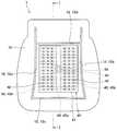
- the seat air conditioner 1includes a seat pad 10, a blower 20, a skin 30, a ventilation sheet 40, and the like.
- the skin 30is indicated by a dashed line in order to clearly distinguish the skin 30 from other configurations.
- the seat pad 10constitutes a seat on which an occupant sits.
- the seat pad 10is formed of foamed urethane or the like and is provided on a frame material (not shown). Thereby, the seat pad 10 can elastically support the load when the occupant is seated.
- the seat pad 10has a pad hole 11 through which an air flow generated by the blower 20 flows. The pad hole 11 penetrates in the thickness direction of the seat pad 10.
- the blower 20is installed under a seat, for example, and generates an air current by rotating an impeller (not shown) by driving a motor (not shown).
- a centrifugal fan, an axial fan, a diagonal fan, or the likecan be employed as the blower 20.
- a duct 21is connected to the blower 20.
- a sealing material 22is provided between the duct 21 and the seat pad 10. The sealing material 22 prevents the airflow from leaking from the connection portion between the duct 21 and the seat pad 10.
- the airflow generated by driving the blower 20passes through the duct 21 and is supplied to the pad hole 11 of the seat pad 10.
- the airflow generated by the blower 20flows in the pad hole 11 of the seat pad 10.
- the seat pad 10has a plurality of suspension grooves 12 for fixing the skin 30.
- the hanging grooves 12are provided on the left and right sides and the front and rear sides of the seat-side surface of the seat pad 10.
- the suspension groove 12includes two left and right suspension grooves 12a and 12b extending in the front-rear direction and two front and rear suspension grooves 12c and 12d extending in the left-right direction so as to connect the left and right suspension grooves 12a and 12b. It is comprised by.
- a pad-side wire 13is provided in the deep portion of the hanging groove 12. The pad side wire 13 is embedded in the seat pad 10 by insert molding, and a part of the pad side wire 13 is exposed in the hanging groove 12.
- the epidermis 30covers the surface of the seat pad 10.
- the skin 30covers the seat-side surface of the seat pad 10 and the front-rear and left-right surfaces.
- the skin 30is formed of a material having air permeability. Examples of the material of the skin 30 include leather, woven fabric, non-woven fabric, resin sheet or mesh sheet having a large number of pores.
- the skin 30has a hanging portion 31 at a position corresponding to the hanging groove 12 provided in the seat pad 10.
- the suspending portion 31is a portion where a portion where the ends of the plurality of divided members constituting the skin 30 are stitched together extends to the deep portion side of the suspending groove 12.
- the hanging part 31is provided with a skin-side wire 32.
- the portion where the pad side wire 13 is exposed to the hanging groove 12 and the skin side wire 32are caulked and fixed by a C-shaped fixing bracket 33. Thereby, the suspension part 31 provided in the skin 30 is fixed in the suspension groove 12 of the seat pad 10, and the skin 30 is attached in a state of being in close contact with the surface of the seat pad 10.
- the ventilation sheet 40is installed between the seat pad 10 and the skin 30.
- the ventilation sheet 40is provided in a recess provided on the surface of the seat pad 10. Thereby, compared with the case where a dent is not provided in the surface of the seat pad 10, the ventilation sheet 40 does not protrude and the sitting comfort is good.
- the ventilation sheet 40is disposed between the plurality of hanging grooves 12 and the hanging grooves 12. Therefore, since the suspension groove 12 is not covered with the ventilation sheet 40, the seat pad 10 and the skin 30 can be easily fixed.
- the ventilation sheet 40includes a ventilation sheet body 41, a plurality of openings 42, a cylindrical portion 43, a connection passage 44, and the like, and these configurations are integrally formed. is there.
- a material for forming the ventilation sheet 40it is preferable to employ rubber or elastomer. Thereby, it is possible to improve the comfort of the passenger.
- the ventilation sheet main body 41is formed in a thin plate shape and has a plurality of ventilation paths 45 through which airflow flows.
- the surface of the ventilation sheet 40is planar.
- the surface of the ventilation sheet 40may have an uneven shape. In that case, for example, as shown in FIGS. 16 and 17, the ventilation sheet 40 may have a shape in which a plurality of tubes having ventilation paths 45 are integrally formed.
- the plurality of ventilation paths 45 included in the ventilation sheet main body 41are connected to the trunk ventilation path 45 a extending to the center and the trunk ventilation path 45 a and to each other. It is comprised by the branch ventilation path 45b extended in parallel.
- the arrangement and shape of the main ventilation path 45a and the branch ventilation path 45b of the plurality of ventilation paths 45can be arbitrarily set.
- the cross-sectional shape of the inner wall of the branch ventilation path 45bis a round shape. Thereby, the rigidity of the ventilation sheet main body 41 is increased, and when the occupant is seated in the seat, the ventilation sheet main body 41 is prevented from being crushed and the cross-sectional area of the ventilation path 45 is reduced.
- the cross-sectional shape of the branch ventilation path 45bcan be set arbitrarily.
- the plurality of openings 42communicate with the ventilation path 45 and open on the surface of the ventilation sheet body 41 on the skin 30 side.
- the position and number of the plurality of openings 42can be arbitrarily set.
- the opening 42is also provided at the tip 451 of the branch ventilation path 45 b located on the outer periphery of the ventilation sheet main body 41.
- the cylindrical portion 43is provided in the central region of the ventilation sheet main body 41 and extends in a cylindrical shape from the ventilation sheet main body 41 to the seat pad 10 side.
- the central area of the ventilation sheet main body 41refers to an area inside the outer edge of the ventilation sheet main body 41.
- a connection passage 44is formed inside the cylindrical portion 43. Therefore, the connection passage 44 is provided in the central region of the ventilation sheet main body 41.
- the connection passage 44 inside the tubular portion 43is open to the ventilation path 45 of the ventilation seat body 41 at a position corresponding to between the thighs of the seated occupant. By opening the cylindrical portion 43 at that position, the cylindrical portion 43 is less susceptible to seating pressure than when opening to the occupant's buttocks and thighs, thereby reducing ventilation resistance and generating wind. Easy configuration.
- the connection passage 44opens to the ventilation path 45 of the ventilation sheet main body 41 and opens to the end of the tubular portion 43 opposite to the ventilation sheet main body 41.
- the cylindrical portion 43is press-fitted and fixed in a pad hole 11 provided in the seat pad 10.
- the connection passage 44communicates with the pad hole 11 in a state where the cylindrical portion 43 is press-fitted into the pad hole 11.
- the seat air conditioner 100 of the first comparative examplewill be described.
- the seat pad 10 provided in the seat air conditioner 100 of the first comparative exampledoes not have a pad hole through which airflow flows.
- the ventilation sheet 400does not include a connection passage in the central region, and air is introduced into the ventilation path 45 from one end 47 of the ventilation sheet 400. Therefore, the ventilation seat 400 curves from the seat surface side of the seat pad 10 along the shape of the end surface of the seat pad 10 on the rear side in the vehicle traveling direction, and is connected to the blower 20 provided under the seat pad 10. ing.
- the ventilation path 45 formed inside the ventilation sheet 400is also curved, so that the ventilation resistance of the ventilation path 45 is increased. Therefore, in the first comparative example, there is a problem that the amount of air blown into the vehicle interior from the plurality of openings 42 or the amount of air sucked into the plurality of openings 42 of the air in the vehicle interior is reduced.
- the ventilation sheet 400 of the first comparative examplecovers a part of the hanging groove 12d provided on the seat surface rear side of the seat pad 10. Therefore, in the first comparative example, it is difficult to fix the seat pad 10 and the skin 30.
- the seat air conditioner 101 of the second comparative exampleincludes two ventilation sheets 401 and 402, and two blowers 201 provided corresponding to the two ventilation sheets 401 and 402, 202.
- One of the two ventilation sheets 401 and 402is provided on the front side of the suspension groove 12 c provided on the seat surface front side of the seat pad 10.
- the ventilation seat 401is curved along the shape of the end face on the front side in the vehicle traveling direction of the seat pad 10 and is connected to the blower 201 provided under the seat pad 10.
- the other ventilation sheet 402 of the two ventilation sheets 401, 402is between the suspension groove 12c provided on the seat surface front side of the seat pad 10 and the suspension groove 12d provided on the seat surface rear side. Is provided.
- the ventilation sheet 402passes through the through hole 14 provided in the seat pad 10 and is connected to the blower 202 provided under the seat pad 10.
- the ventilation seat 40 and the seat air conditioner 1 of the first embodiment described abovehave the following operational effects.
- connection passage 44communicates with the ventilation path 45 of the ventilation sheet body 41 and also communicates with the pad hole 11 provided in the seat pad 10.
- the ventilation seat 40is not curved along the front end surface or the rear end surface of the vehicle traveling direction in the seat pad 10 as in the first and second comparative examples, but on the seat surface side of the seat pad 10. It is provided in a substantially flat state. Therefore, the ventilation resistance of the ventilation path 45 which the ventilation sheet 40 has becomes small. Therefore, this ventilation sheet 40 can increase the amount of air blown out from the plurality of openings 42 into the vehicle interior, and can enhance the comfort of the passenger.
- the ventilation sheet 40can be provided between the seat pad 10 and the skin 30 without covering the hanging groove 12 provided in the seat pad 10. Therefore, by using this ventilation sheet 40, the seat pad 10 and the skin 30 can be easily fixed by the suspension groove 12.
- the ventilation sheet 40is provided with the suspension groove 12 and the suspension groove 12 without increasing the number of ventilation sheets 40 in order to avoid the position of the suspension groove 12 provided in the seat pad 10 as in the second comparative example. It is possible to provide between. Therefore, by using this ventilation sheet 40, it is possible to reduce the number of parts, simplify the configuration, and reduce the manufacturing cost.
- the ventilation sheet 40 of the first embodimentincludes a plurality of branch ventilation paths 45b in which the ventilation sheet body 41 is arranged in parallel.
- the rigidity of the ventilation sheet main body 41is increased by the wall that partitions the plurality of branch ventilation paths 45b and the branch ventilation paths 45b. Therefore, when the occupant sits on the seat, the ventilation seat body 41 is prevented from being crushed and the cross-sectional area of the branch ventilation path 45b is reduced. Therefore, the ventilation sheet 40 can increase the amount of air blown into the vehicle interior from the plurality of openings 42 or the amount of air sucked into the plurality of openings 42 from the air in the vehicle interior.
- the ventilation sheet 40 of the first embodimentis disposed between the plurality of suspension grooves 12 and the suspension grooves 12.
- connection passage 44is provided in the central region of the ventilation sheet main body 41.
- the outer periphery of the ventilation sheet main body 41 and the connection passageare compared with the configuration in which air is introduced into the ventilation path 45 from one end 47 of the ventilation sheets 400, 401, 402 as in the first and second comparative examples. It is possible to make the distance to 44 substantially uniform. Therefore, when air is supplied from the pad hole 11 to the connection passage 44, the air can be blown out from the plurality of openings 42 almost uniformly.
- the ventilation sheet 40 of the first embodimenthas a cylindrical portion 43 that extends in a cylindrical shape from the ventilation sheet main body 41 and in which a connection passage 44 is formed.
- the ventilation sheet 40can be easily assembled to the seat pad 10 by press-fitting the tubular portion 43 into the pad hole 11 of the seat pad 10.
- the ventilation sheet main body 41 and the cylindrical portion 43 constituting the ventilation sheet 40 of the first embodimentare formed to include rubber or elastomer.
- the ventilation seat 40can improve the sitting comfort of the occupant.
- the cross section of the inner wall of the ventilation path 45is round.
- the rigidity of the ventilation sheet body 41is increased. Therefore, when the occupant sits on the seat, the ventilation seat body 41 can be prevented from being crushed and the cross-sectional area of the ventilation path 45 can be reduced.
- the seat air conditioner 1 of the first embodimentincludes the blower 20, the seat pad 10, the skin 30, and the ventilation seat 40.
- the connection passage 44 included in the ventilation sheet 40communicates with the ventilation path 45 and communicates with the pad hole 11 provided in the seat pad 10.
- the ventilation sheet 40is installed in the seat air conditioning apparatus 1 on the seat surface side of the seat pad 10 in a substantially flat state, the plurality of openings of the ventilation sheet 40 are provided as compared with the first and second comparative examples.
- the amount of air blown from the portion 42 into the vehicle interiorcan be increased, and passenger comfort can be enhanced.
- the seat air conditioner 1can install the ventilation seat 40 without covering the suspension groove 12 provided in the seat pad 10, the seat pad 10 and the skin 30 are easily fixed by the suspension groove 12. can do.
- the seat air conditioner 1can reduce the number of parts of the ventilation sheet 40 and the blower 20, simplify the configuration, and reduce the manufacturing cost as compared with the second comparative example.
- FIG. 8shows the cross-sectional shape of the branch ventilation path 45b among the trunk ventilation paths 45a and the branch ventilation paths 45b constituting the plurality of ventilation paths 45 of the ventilation sheet main body 41.
- the cross section of the inner wall of the branch ventilation path 45bis polygonal shape.
- the ventilation sheet 40suppresses the fall of the ventilation resistance of the ventilation path 45 when a passenger
- This 2nd Embodimentcan also have the same operation effect as a 1st embodiment.
- 3rd Embodimentchanges the flow direction of the airflow formed with the air blower 20 with respect to 1st Embodiment, Since it is the same as that of 1st Embodiment about others, it is a different part from 1st Embodiment. Only will be described.
- the third embodimentwhen the blower 20 is driven, the air in the duct 21 and the pad hole 11 is sucked into the blower 20, and the connection passage 44 and the ventilation passage of the ventilation sheet 40. The pressure of 45 drops. Therefore, as shown by the arrow F, the air in the passenger compartment passes through the skin 30 and is sucked into the ventilation path 45 of the ventilation sheet 40 from the plurality of openings 42. Thereby, this seat air conditioner 1 prevents the stuffiness between the seat air conditioner 1 and the occupant by sucking in hot air between the occupant seated there and the skin 30, and improves the comfort of the occupant. Is possible. Therefore, the third embodiment can also achieve the same operational effects as the first and second embodiments.
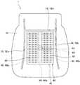
- 4th Embodimentchanges the position of the suspension groove 12 provided in the seat pad 10 with respect to 1st Embodiment, and since it is the same as that of 1st Embodiment about others, 1st Embodiment and Only the different parts will be described.
- the suspension grooves 12 provided in the seat pad 10are provided on the left and right sides and the rear side of the seating surface side surface of the seat pad 10.
- the suspending groove 12includes two left and right suspending grooves 12a and 12b extending in the front-rear direction, and one rear suspending groove 12d extending in the left and right direction so as to connect the left and right suspending grooves 12a and 12b. It is configured.
- no hanging grooveis provided on the front side of the seat pad 10 surface.
- the ventilation sheet 40is disposed between the plurality of suspension grooves 12a, the suspension grooves 12b, and the suspension grooves 12d.
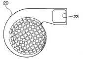
- the blower 20has an air outlet or a suction port 23 connected to the pad hole 11 provided in the seat pad 10.
- the number of parts constituting the seat air conditioner 1can be reduced, the configuration can be simplified, and the manufacturing cost can be reduced.
- the fifth embodimentcan also achieve the same operational effects as the first to fourth embodiments.
- a ventilation seat 40is installed on the back seat pad 15 constituting the backrest that supports the back of the occupant.
- the ventilation sheet 40is provided between the back sheet pad 15 and the skin 35 covering the back sheet pad 15.
- the ventilation sheet 40is disposed between the plurality of suspension grooves 12 provided on the back seat pad 15 and the suspension grooves 12. Therefore, since the suspension groove 12 is not covered with the ventilation sheet 40, the back sheet pad 15 and the skin 35 can be easily fixed.
- the cylindrical portion 43 provided in the ventilation sheet 40is press-fitted and fixed in the pad hole 16 provided in the back seat pad 15.
- the airflow generated by driving the blower 20 provided on the back seat pad 15flows into the connection passage 44 via the duct 21 and the pad hole 16 of the back seat pad 15.
- the airflowis blown out from the plurality of openings 42 through the skin 35 into the vehicle interior as indicated by an arrow I.
- the sixth embodimentcan also achieve the same operational effects as the first to fifth embodiments.
- 7th Embodimentinstalls the ventilation sheet
- the suspension groove 12 of the seat pad 10has a lateral direction so as to connect the left and right suspension grooves 12 a and 12 b extending in the front-rear direction and the left and right suspension grooves 12 a and 12 b.
- Three suspension grooves 12c, 12d, and 12e extending in the left-right directionare provided at the front, rear, and intermediate portions of the seat pad 10.
- the ventilation sheet 50is provided between the left and right suspension grooves 12a and 12b, and is disposed between the front suspension groove 12c and the rear suspension groove 12d of the seat pad 10. Therefore, the ventilation sheet 50 is provided so as to straddle the suspension groove 12e in the middle part of the seat pad 10.
- the ventilation sheet 50includes a connecting member 53 at a position corresponding to the suspension groove 12e in the middle part of the seat pad 10.
- the connecting member 53has a groove shape that can be inserted at least in part into the suspension groove 12e of the seat pad 10, and enters the suspension groove 12e.
- the connecting member 53has a plurality of through holes 54 penetrating in the thickness direction.
- the groove shape of the connecting member 53is not limited to a substantially U-shaped cross section as shown in the figure, and can be arbitrarily set such as a V-shaped or U-shaped cross section.
- the pad-side wire 13is exposed in the suspension groove 12e in the middle portion of the seat pad 10.
- the through hole 54 of the connecting member 53is provided at a position corresponding to the position where the pad side wire 13 is exposed in the hanging groove 12e.
- the skin 30has a hanging portion 31 and a skin-side wire 32 at locations corresponding to the hanging grooves 12e.
- the hanging portion 31 and the skin-side wire 32can be inserted through the through hole 54 of the connecting member 53. Therefore, the skin-side wire 32 inserted through the through hole 54 of the connecting member 53 and the pad-side wire 13 exposed in the suspension groove 12e in the intermediate portion of the seat pad 10 are fixed by caulking with a C-shaped fixing bracket 33. Is done.
- the suspension part 31 provided in the skin 30is fixed in the suspension groove 12e of the seat pad 10, and the skin 30 is attached in a state of being in close contact with the surface of the seat pad 10.
- the ventilation sheet 50includes a first ventilation sheet main body 51 provided on one side with a coupling member 53 interposed therebetween, and a second ventilation sheet main body 52 provided on the other side. ing.
- the first ventilation sheet main body 51has a plurality of first ventilation paths 511 and a plurality of first openings 512.
- the second ventilation sheet main body 52also has a plurality of second ventilation paths 521 and a plurality of second openings 522.
- the ventilation sheet 50includes a cylindrical portion 43 on the first ventilation sheet main body 51 side.
- a connection passage 44 that communicates with the first ventilation passage 511is formed in the tubular portion 43.
- the 1st ventilation sheet main body 51 and the cylindrical part 43are integrally formed by rubber
- the second ventilation sheet main body 52is also formed of rubber or elastomer.
- the first ventilation sheet main body 51 of the seventh embodimenthas a shape in which a plurality of tubes having the first ventilation path 511 are integrally formed. Therefore, the 1st ventilation sheet main body 51 has the some 1st ventilation path 511 arrange
- the second ventilation sheet main body 52has a shape in which a plurality of tubes having the second ventilation path 521 are integrally formed. Therefore, the 2nd ventilation sheet main body 52 also has the some 2nd ventilation path 521 arrange
- the surface of the 2nd ventilation sheet main body 52is also a shape which has an unevenness
- the connecting member 53 described aboveis formed of a resin such as polyethylene or polypropylene.
- a third ventilation path 531is formed inside the connecting member 53.
- both the end portion of the first ventilation sheet main body 51 and the end portion of the second ventilation sheet main body 52are inserted into the third ventilation path 531 included in the connecting member 53. Accordingly, the first ventilation sheet main body 51, the second ventilation sheet main body 52, and the connecting member 53 are connected, and the first ventilation sheet 511 included in the first ventilation sheet main body 51 and the second ventilation sheet main body 52 are included.
- the airflow generated in the blower 20flows into the connection passage 44 via the duct 21 and the pad hole 11.
- a part of the airflowflows from the connection passage 44 through the first ventilation path 511 of the first ventilation sheet main body 51 and, as indicated by the arrow L, from the plurality of first openings 512 of the first ventilation sheet main body 51, the skin. Pass through 30 and blow out into the passenger compartment.
- a part of the airflow flowing through the first ventilation path 511 of the first ventilation sheet main body 51passes through the third ventilation path 531 of the connecting member 53 and flows through the second ventilation path 521 of the second ventilation sheet main body 52.
- the airis blown out from the plurality of second openings 522 of the second ventilation sheet main body 52 through the skin 30 into the vehicle interior.
- crew who seated on the seat air conditioner 1 and the skin 30is discharged
- connection member 53in the ventilation sheet 50, even when the suspension grooves 12c, 12d, and 12e are provided in the front part, the rear part, and the intermediate part of the seat pad 10, respectively,
- the ventilation sheet 50can be provided so as to straddle the suspension groove 12e.
- the ventilation seat 50is substantially flat on the seat surface side of the seat pad 10 without being curved along the front end surface or the rear end surface of the seat pad 10 in the vehicle traveling direction as in the first comparative example. Provided in a state. Therefore, the ventilation resistance of the 1st, 2nd, 3rd ventilation path 511, 521, 531 which the ventilation sheet 50 has becomes small. Therefore, this ventilation sheet 50 can increase the amount of air blown out from the plurality of openings 512 and 522 into the vehicle interior, and can enhance the comfort of the passenger.
- the ventilation sheet 50 of 7th Embodimenteven when the suspension grooves 12c, 12d, and 12e are provided in the front part, the intermediate part, and the rear part of the seat pad 10, respectively, the seat pad 10 and the skin 30 and Can be easily fixed by the suspension groove 12.
- the ventilation sheet 50straddles the suspension groove 12e in the intermediate portion without increasing the number of ventilation sheets 50 in order to avoid the position of the suspension groove 12 provided in the seat pad 10 as in the second comparative example.
- the ventilation sheet 50can be provided. Therefore, by using this ventilation sheet 50, it is possible to reduce the number of parts, simplify the configuration, and reduce the manufacturing cost.
- the first and second ventilation sheet bodies 51 and 52are formed by integrally forming a plurality of tubes having the first and second ventilation paths 511 and 521.
- the seventh embodimentcan achieve the same effects as the first to sixth embodiments.
- the air blower 20was installed in the lower part or back surface of the seat pad 10.
- the blower 20may be installed so as to be embedded in the seat pad 10.
- the air blower 20may utilize the air blower of an air conditioner.
- the airflowis configured to flow from the air conditioning case to the seat hole via a duct or the like.
- the seat air conditioner 1has the ventilation seats 40 installed on each of the seat pad 10 constituting the seat on which the occupant sits and the back seat pad 15 constituting the backrest.
- the seat air conditioner 1is configured to install the ventilation seat 40 only on the back seat pad 15 without installing the ventilation seat 40 on the seat pad 10 that constitutes the seat on which the occupant is seated. It is good.
- the ventilation seat installed between the seat pad constituting the vehicle seat and the skinincludes the ventilation seat body and the plurality of openings. And a connecting passage.
- the ventilation sheet main bodyis formed in a thin plate shape and has a ventilation path through which an airflow flows.
- the plurality of openingscommunicate with the ventilation path of the ventilation sheet main body and open on the surface of the ventilation sheet main body on the skin side.
- the connection passagecommunicates with the ventilation path of the ventilation sheet main body and also communicates with a pad hole provided in the seat pad.
- the ventilation sheet bodyhas a plurality of ventilation paths arranged in parallel.
- the rigidity of the ventilation sheet main bodyis increased by the wall that partitions the plurality of ventilation paths. Therefore, when the occupant sits on the seat, the ventilation seat body is prevented from being crushed and the cross-sectional area of the ventilation path is reduced. Therefore, this ventilation sheet can increase the amount of air blown out from the plurality of openings into the vehicle interior or the amount of air sucked into the plurality of openings from the air in the vehicle interior.
- the ventilation sheet bodyis formed by integrally forming a plurality of tubes having ventilation paths.
- the ventilation sheet bodyhas a plurality of ventilation paths arranged in parallel.
- the seat padhas a plurality of suspension grooves for fixing the skin.
- the ventilation sheetis disposed between the plurality of suspension grooves and the suspension grooves.
- the ventilation sheetis provided without covering the hanging groove, the seat pad and the skin can be easily fixed by the hanging groove.
- connection passageis provided in the central region of the ventilation sheet body.
- the ventilation sheethas a cylindrical portion that extends in a cylindrical shape from the ventilation sheet main body and in which a connection passage is formed.
- the ventilation sheet main body and the cylindrical portionare formed including rubber or elastomer.
- the cross section of the inner wall of the ventilation path which a ventilation sheet main body hasis round shape or polygonal shape.
- the ventilation sheet main bodyincludes a first ventilation sheet main body and a second ventilation sheet main body.
- the ventilation sheetconnects the first ventilation sheet main body and the second ventilation sheet main body, and communicates the first ventilation path of the first ventilation sheet main body with the second ventilation path of the second ventilation sheet main body.
- a connecting member having a ventilation pathis further provided.
- the connecting memberhas a groove shape in which at least a part of the connecting member can be inserted into the suspension groove of the seat pad, and has a through hole that communicates in the thickness direction.
- a seat air conditioner installed in a passenger compartment of a vehicleincludes a blower that generates an air flow, a seat pad that has a pad hole through which the air flow generated by the blower flows, and a skin that covers a surface of the seat pad. And a ventilation sheet installed between the seat pad and the skin. This ventilation sheet has been described in the first aspect.
- this seat air conditionercan exhibit the same effects as the ventilation seat of the first aspect described above.
- the seat padhas a plurality of suspension grooves for fixing the epidermis.
- the epidermishas a suspension part fixed in the suspension groove at a position corresponding to the suspension groove provided in the seat pad.
- a ventilation sheetis arrange
- the ventilation sheetis provided without covering the hanging groove, the seat pad and the skin can be easily fixed by the hanging groove.
Landscapes
- Engineering & Computer Science (AREA)
- Mechanical Engineering (AREA)
- Aviation & Aerospace Engineering (AREA)
- Transportation (AREA)
- Power Engineering (AREA)
- Physics & Mathematics (AREA)
- Thermal Sciences (AREA)
- Chair Legs, Seat Parts, And Backrests (AREA)
- Air-Conditioning For Vehicles (AREA)
- Seats For Vehicles (AREA)
Abstract
Description
Translated fromJapanese本出願は、2016年10月24日に出願された日本特許出願番号2016-207963号に基づくもので、ここにその記載内容が参照により組み入れられる。This application is based on Japanese Patent Application No. 2016-207963 filed on Oct. 24, 2016, the description of which is incorporated herein by reference.
本開示は、通風シート、および、それを備えた座席空調装置に関するものである。The present disclosure relates to a ventilation seat and a seat air conditioner including the ventilation seat.
従来、車両の座席を構成するシートパッドに形成した複数の通気口からシートパッドを覆う表皮を経由して車室内に空気を吹き出し、または、車室内の空気をその複数の通気口に吸い込むことの可能な座席空調装置が知られている。Conventionally, air has been blown out from a plurality of vents formed in a seat pad constituting a seat of a vehicle through a skin covering the seat pad into the vehicle interior, or air in the vehicle interior is sucked into the plurality of vents. Possible seat air conditioners are known.
特許文献1には、シートパッドに複数の通気口を形成することに代えて、シートパッドと表皮との間に通風シートを配置する技術が記載されている。この通風シートは、複数のチューブを並列に配置し、一体化したものである。複数のチューブにはそれぞれ、通風シートの内側に形成された通風路に連通する複数の開口部が設けられている。通風シートは、シートパッドの座面側に配置されると共に、その座面側に配置された部位から、シートパッドのうち車両進行方向前側の端面または後側の端面を経由して、シートパッドの下に設けられた送風機に接続されている。送風機の駆動により通風シートの内側に形成された通風路に気流が生じると、通風路に連通する複数の開口部から車室内に空気が吹き出し、または、車室内の空気がその複数の開口部から通風路に吸い込まれる。
しかしながら、特許文献1に記載の通風シートは、通風シートの内側に形成された通風路が、シートパッドのうち車両進行方向前側の端面または後側の端面の形状に沿って湾曲しているので、通風路の通気抵抗が大きいものとなる。したがって、この通風シートは、複数の開口部から車室内へ吹き出す風量、または、車室内の空気を複数の開口部に吸い込む風量が低減するといった問題がある。However, in the ventilation sheet described in
また、特許文献1に記載の通風シートは、シートパッドと表皮とを接続するための吊り溝を覆うように設けられている。そのため、この通風シートを使用した場合、シートパッドと表皮とを固定することが困難になる。Moreover, the ventilation sheet described in
さらに、特許文献1では、通風シートによって吊り溝を覆うことのない実施例として、吊り溝に対し車両進行方向前側に第1の通風シートを設け、吊り溝に対し車両進行方向後側に第2の通風シートを設けることが記載されている。この実施例では、第1の通風シートに対して1個の送風機が接続され、第2の通風シートに対しても1個の送風機が接続されている。このように、1個のシートパッドに対し、2枚の通風シートおよび2個の送風機を設けると、部品点数が増加し、構成が複雑になると共に、製造上のコストが増加することが懸念される。Further, in
本開示は、通風量を増加すると共に、シートパッドと表皮との固定を容易に行うことの可能な通風シートおよび座席空調装置を提供することを目的とする。The present disclosure is intended to provide a ventilation seat and a seat air conditioner that can increase the amount of ventilation and can easily fix the seat pad and the skin.
本開示の1つの観点によれば、車両の座席を構成するシートパッドと表皮との間に設置される通風シートであって、
薄板状に形成され、気流が流れる通風路を有する通風シート本体と、
通風シート本体の通風路に連通すると共に、通風シート本体のうち表皮側の面に開口する複数の開口部と、
通風シート本体の通風路に連通すると共に、シートパッドに設けられたパッド孔に連通する接続通路と、を備える。According to one aspect of the present disclosure, a ventilation seat installed between a seat pad and a skin constituting a seat of a vehicle,
A ventilation sheet main body formed in a thin plate shape and having a ventilation path through which airflow flows,
While communicating with the ventilation path of the ventilation sheet main body, a plurality of openings that open to the skin side surface of the ventilation sheet main body,
A communication passage that communicates with the ventilation path of the ventilation seat body and communicates with a pad hole provided in the seat pad.
これにより、通風シートには、パッド孔から、接続通路→通風路→複数の開口部の順に、またはその逆順に気流が流れる。そのため、通風シートは、シートパッドのうち車両進行方向前側の端面または後側の端面に沿って湾曲することなく、シートパッドの座面側にほぼ平坦な状態で設置することが可能である。そのため、通風路の通気抵抗が小さいものとなる。したがって、この通風シートは、複数の開口部から車室内に吹き出す風量、または、車室内の空気を複数の開口部に吸い込む風量を増加することができる。Thus, the airflow flows through the ventilation sheet from the pad hole in the order of the connection passage → the ventilation path → the plurality of openings or vice versa. Therefore, the ventilation seat can be installed in a substantially flat state on the seat surface side of the seat pad without being curved along the front end surface or the rear end surface of the seat pad in the vehicle traveling direction. Therefore, the ventilation resistance of the ventilation path is small. Therefore, this ventilation sheet can increase the amount of air blown out from the plurality of openings into the vehicle interior or the amount of air sucked into the plurality of openings from the air in the vehicle interior.
また、この通風シートは、シートパッドに設けられる吊り溝を覆うことなく、吊り溝と吊り溝との間に設けることが可能である。そのため、この通風シートを用いることで、シートパッドと表皮とを吊り溝により容易に固定することができる。Moreover, this ventilation sheet can be provided between the suspending groove and the suspending groove without covering the suspending groove provided on the seat pad. Therefore, by using this ventilation sheet, the seat pad and the skin can be easily fixed by the hanging groove.
さらに、この通風シートは、シートパッドに設けられた吊り溝の位置を避けるために通風シートの数を増加することなく、吊り溝と吊り溝との間に設けることが可能である。したがって、この通風シートを用いることで、部品点数を低減し、構成を簡素化すると共に、製造上のコストを低減することが可能である。Furthermore, this ventilation sheet can be provided between the suspension groove and the suspension groove without increasing the number of ventilation sheets in order to avoid the position of the suspension groove provided on the seat pad. Therefore, by using this ventilation sheet, it is possible to reduce the number of parts, simplify the configuration, and reduce manufacturing costs.
また、別の観点によれば、車両の車室内に設置される座席空調装置であって、
気流を発生させる送風機と、
送風機により発生した気流が流れるパッド孔を有するシートパッドと、
シートパッドの表面を覆う表皮と、
シートパッドと表皮との間に設置される上記1つの観点で述べた通風シートと、を備える。According to another aspect, a seat air conditioner installed in a passenger compartment of a vehicle,
A blower that generates an airflow;
A seat pad having pad holes through which airflow generated by the blower flows;
An epidermis covering the surface of the seat pad,
The ventilation sheet described in the said one viewpoint installed between a seat pad and an outer skin is provided.
これにより、別の観点による開示は、上述した1つの観点で述べた開示と同様の作用効果を奏することが可能である。Thereby, the disclosure from another viewpoint can achieve the same effects as the disclosure described in the above-mentioned one viewpoint.
以下、本開示の実施形態について図に基づいて説明する。なお、以下の各実施形態相互において、互いに同一もしくは均等である部分には、同一符号を付して説明を行う。Hereinafter, embodiments of the present disclosure will be described with reference to the drawings. In the following embodiments, parts that are the same or equivalent to each other will be described with the same reference numerals.
(第1実施形態)
第1実施形態について図面を参照しつつ説明する。本実施形態の座席空調装置は、車両の車室内に設置され、座面から車室内に空気を吹き出し、または車室内の空気を座面に吸い込むことにより、座席空調装置と乗員との間の蒸れを防ぎ、乗員の快適性を向上するものである。(First embodiment)
A first embodiment will be described with reference to the drawings. The seat air conditioner according to the present embodiment is installed in a vehicle interior of a vehicle, and blows air from the seat surface into the vehicle interior or sucks air from the vehicle interior into the seat surface, thereby suffocating between the seat air conditioner and the occupant. Prevent passengers and improve passenger comfort.
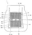
図1に示すように、座席空調装置1は、シートパッド10、送風機20、表皮30および通風シート40などを備えている。なお、図1などでは、表皮30とその他の構成とを明確に区別するために、表皮30を一点鎖線で示している。As shown in FIG. 1, the
シートパッド10は、乗員が着座する座席を構成するものである。シートパッド10は、発泡ウレタンなどにより形成され、図示していないフレーム材の上に設けられている。これにより、シートパッド10は、乗員が着座したときの荷重を弾性的に支持することが可能である。シートパッド10は、送風機20により発生した気流が流れるパッド孔11を有している。パッド孔11は、シートパッド10の厚み方向に貫通している。The
送風機20は、例えば座席の下に設置され、図示していないモータの駆動により図示していない羽根車を回転させることにより気流を発生させるものである。送風機20として、例えば遠心ファン、軸流ファンまたは斜流ファンなどを採用することが可能である。送風機20には、ダクト21が接続されている。ダクト21とシートパッド10との間には、シール材22が設けられている。シール材22は、ダクト21とシートパッド10との接続箇所から気流が漏れることを防いでいる。矢印Aに示すように、送風機20の駆動により発生した気流は、ダクト21を通り、シートパッド10のパッド孔11に供給される。これにより、矢印Bに示すように、シートパッド10のパッド孔11には、送風機20により発生する気流が流れる。The
また、シートパッド10は、表皮30を固定するための複数の吊り溝12を有している。図2に示すように、吊り溝12は、シートパッド10の座面側の面のうち左右および前後に設けられている。詳細には、吊り溝12は、前後方向に延びる左右2本の吊り溝12a、12bと、その左右の吊り溝12a、12bを接続するように左右方向に延びる前後2本の吊り溝12c、12dにより構成されている。図3に示すように、吊り溝12の深部には、パッド側ワイヤー13が設けられている。パッド側ワイヤー13は、インサート成形によりシートパッド10に埋設され、その一部が吊り溝12の中に露出している。Further, the
図1に示すように、表皮30は、シートパッド10の表面を覆っている。詳細には、表皮30は、シートパッド10の座面側の面と前後左右の面を覆っている。表皮30は、通気性を有する材料により形成されている。表皮30の材料として、例えば多数の細孔を有する皮革、織布、不織布、樹脂シートまたはメッシュシートなどが挙げられる。表皮30は、シートパッド10に設けられた吊り溝12に対応する位置に、吊り部31を有している。図3に示すように、吊り部31は、表皮30を構成する複数の分割部材の端部同士が縫い合わされた箇所が、吊り溝12の深部側に延びている部位である。吊り部31には、表皮側ワイヤー32が設けられている。上述したパッド側ワイヤー13が吊り溝12に露出している箇所と、表皮側ワイヤー32とが、C字状の固定金具33によってかしめ固定される。これにより、表皮30に設けられた吊り部31がシートパッド10の吊り溝12内で固定され、表皮30は、シートパッド10の表面に密着した状態で取り付けられる。As shown in FIG. 1, the
図1に示すように、通風シート40は、シートパッド10と表皮30との間に設置されている。通風シート40は、シートパッド10の表面に設けられた凹みに設けられている。これにより、シートパッド10の表面に凹みを設けない場合に比べて、通風シート40が出っ張らず、座り心地が良いものとなる。また、図2に示すように、通風シート40は、複数の吊り溝12と吊り溝12との間に配置されている。そのため、吊り溝12が通風シート40によって覆われることがないので、シートパッド10と表皮30とを容易に固定することが可能である。As shown in FIG. 1, the
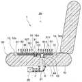
図4から図7に示すように、通風シート40は、通風シート本体41、複数の開口部42、筒状部43および接続通路44などを備えおり、それらの構成が一体に形成されたものである。通風シート40を形成する材料として、ゴムまたはエラストマーを採用することが好ましい。これにより、乗員の座り心地を良くすることが可能である。As shown in FIGS. 4 to 7, the
通風シート本体41は、薄板状に形成されており、気流が流れる複数の通風路45を有している。第1実施形態では、通風シート40の表面は、平面状である。なお、後述する第7実施形態で説明するように、通風シート40の表面は、凹凸を有する形状としてもよい。その場合、例えば、図16および図17に示すように、通風シート40は、通風路45を有する複数のチューブが一体に形成された形状とすることも可能である。The ventilation sheet
図4から図6に示すように、第1実施形態では、通風シート本体41が有する複数の通風路45は、中央部に延びる幹通風路45a、および、その幹通風路45aに連通すると共に互いに並列に延びる枝通風路45bによって構成されている。なお、複数の通風路45が有する幹通風路45aおよび枝通風路45bの配置および形状は、任意に設定することが可能である。As shown in FIGS. 4 to 6, in the first embodiment, the plurality of
図7に示すように、枝通風路45bの内壁の断面形状は、丸形状である。これにより、通風シート本体41の剛性が高くなり、座席に乗員が着座した際に、通風シート本体41が潰れて通風路45の断面積が小さくなることが抑制される。なお、枝通風路45bの断面形状は、任意に設定することが可能である。As shown in FIG. 7, the cross-sectional shape of the inner wall of the branch ventilation path 45b is a round shape. Thereby, the rigidity of the ventilation sheet
複数の開口部42は、通風路45に連通すると共に、通風シート本体41のうち表皮30側の面に開口している。複数の開口部42の位置および数は、任意に設定することが可能である。図6に示したように、開口部42は、通風シート本体41の外周に位置する枝通風路45bの先端部451にも設けられている。なお、開口部42は、枝通風路45bだけでなく、幹通風路45aの表皮30側の面に設けてもよい。The plurality of
筒状部43は、通風シート本体41の中央領域に設けられ、通風シート本体41からシートパッド10側に筒状に延びている。なお、通風シート本体41の中央領域とは、通風シート本体41の外縁より内側の領域をいうものである。筒状部43の内側に接続通路44が形成されている。したがって、接続通路44は、通風シート本体41の中央領域に設けられている。この筒状部43の内側の接続通路44は、着座した乗員の両太ももの間に対応した位置で、通風シート本体41の通風路45に開口している。その位置に筒状部43が開口することで、乗員の尻部や太ももの真下に開口する場合に比べて、筒状部43が着座圧を受け難いため、通風抵抗が少なくなり、風が出易い構成となる。接続通路44は、通風シート本体41の通風路45に開口すると共に、筒状部43のうち通風シート本体41とは反対側の端部に開口している。The
図1に示すように、筒状部43は、シートパッド10に設けられたパッド孔11に圧入固定される。筒状部43がパッド孔11に圧入された状態で、接続通路44はパッド孔11に連通する。As shown in FIG. 1, the
図1の矢印AおよびBに示したように、送風機20が駆動すると、送風機20で発生した気流は、ダクト21およびパッド孔11を経由し、通風シート40の接続通路44に流入する。この気流は、通風シート本体41の幹通風路45aおよび枝通風路45bを流れた後、矢印Cに示したように、複数の開口部42から表皮30を通り車室内に吹き出される。これにより、座席空調装置1に着座した乗員と表皮30との間の熱気が排出され、乗員の快適性が向上する。1, when the
ここで、上述した第1実施形態の座席空調装置1と比較するため、第1比較例の座席空調装置100について説明する。Here, in order to compare with the
図19に示すように、第1比較例の座席空調装置100が備えるシートパッド10は、気流が流れるパッド孔を有していない。また、通風シート400は、その中央領域に接続通路を備えておらず、通風シート400の一方の端部47から通風路45に空気が導入される構成である。そのため、通風シート400は、シートパッド10の座面側から、シートパッド10のうち車両進行方向後側の端面の形状に沿って湾曲し、シートパッド10の下に設けられた送風機20に接続されている。As shown in FIG. 19, the
この第1比較例のように、通風シート400を湾曲させると、通風シート400の内側に形成された通風路45も湾曲するので、通風路45の通気抵抗が大きくなる。したがって、第1比較例では、複数の開口部42から車室内へ吹き出す風量、または、車室内の空気を複数の開口部42に吸い込む風量が低減するといった問題がある。When the
また、第1比較例の通風シート400は、シートパッド10のうち座面後方側に設けられた吊り溝12dの一部を覆っている。そのため、第1比較例では、シートパッド10と表皮30とを固定することが困難なものとなっている。Moreover, the
次に、第2比較例の座席空調装置101について説明する。Next, the
図20に示すように、第2比較例の座席空調装置101は、2枚の通風シート401、402と、その2枚の通風シート401、402に対応して設けられた2個の送風機201、202を備えている。2枚の通風シート401、402のうち一方の通風シート401は、シートパッド10のうち座面前方側に設けられた吊り溝12cよりも前側に設けられている。この通風シート401は、シートパッド10のうち車両進行方向前側の端面の形状に沿って湾曲し、シートパッド10の下に設けられた送風機201に接続されている。As shown in FIG. 20, the
2枚の通風シート401、402のうち他方の通風シート402は、シートパッド10のうち座面前方側に設けられた吊り溝12cと、座面後方側に設けられた吊り溝12dとの間に設けられている。この通風シート402は、シートパッド10に設けられた貫通穴14を通り、シートパッド10の下に設けられた送風機202に接続されている。The
第2比較例のように、1個のシートパッド10に対し、2枚の通風シート401、402および2個の送風機201、202を設けると、部品点数が増加し、構成が複雑になると共に、製造上のコストが増加することが懸念される。As in the second comparative example, when two
第1および第2比較例に対し、上述した第1実施形態の通風シート40および座席空調装置1は、次の作用効果を奏する。In contrast to the first and second comparative examples, the
(1)第1実施形態の通風シート40は、接続通路44が、通風シート本体41の通風路45に連通すると共に、シートパッド10に設けられたパッド孔11に連通する。(1) In the
これにより、通風シート40は、第1および第2比較例のようにシートパッド10のうち車両進行方向前側の端面または後側の端面に沿って湾曲することなく、シートパッド10の座面側にほぼ平坦な状態で設けられる。そのため、通風シート40が有する通風路45の通気抵抗が小さいものとなる。したがって、この通風シート40は、複数の開口部42から車室内に吹き出す風量を増加し、乗員の快適性を高めることができる。Thereby, the
また、この通風シート40は、シートパッド10に設けられる吊り溝12を覆うことなく、シートパッド10と表皮30との間に設けることが可能である。そのため、この通風シート40を用いることで、シートパッド10と表皮30とを吊り溝12により容易に固定することができる。Further, the
さらに、この通風シート40は、第2比較例のようにシートパッド10に設けられた吊り溝12の位置を避けるために通風シート40の数を増加することなく、吊り溝12と吊り溝12との間に設けることが可能である。したがって、この通風シート40を用いることで、部品点数を低減し、構成を簡素化すると共に、製造上のコストを低減することが可能である。Further, the
(2)第1実施形態の通風シート40は、通風シート本体41が、並列に配置された複数の枝通風路45bを有している。(2) The
これにより、複数の枝通風路45bと枝通風路45bとを仕切る壁により、通風シート本体41の剛性が高くなる。そのため、座席に乗員が着座した際に、通風シート本体41が潰れて枝通風路45bの断面積が小さくなることが抑制される。したがって、この通風シート40は、複数の開口部42から車室内に吹き出す風量、または、車室内の空気を複数の開口部42に吸い込む風量を増加することができる。Thereby, the rigidity of the ventilation sheet
(3)第1実施形態の通風シート40は、複数の吊り溝12と吊り溝12との間に配置されるものである。(3) The
これにより、シートパッド10と表皮30とを吊り溝12により容易に固定することができる。Thereby, the
(4)第1実施形態の通風シート40は、通風シート本体41の中央領域に接続通路44が設けられる。(4) In the
これにより、第1および第2比較例のように通風シート400、401、402の一方の端部47から通風路45に空気が導入される構成に比べて、通風シート本体41の外周と接続通路44との距離を略均一に近づけることが可能である。そのため、パッド孔11から接続通路44に空気が供給されるとき、複数の開口部42からほぼ均一に空気を吹き出すことが可能である。Thereby, the outer periphery of the ventilation sheet
(5)第1実施形態の通風シート40は、通風シート本体41から筒状に延び、接続通路44が形成される筒状部43を有する。(5) The
これにより、筒状部43をシートパッド10のパッド孔11に圧入することで、通風シート40をシートパッド10に容易に組み付けることが可能である。Thereby, the
(6)第1実施形態の通風シート40を構成する通風シート本体41および筒状部43は、ゴムまたはエラストマーを含んで形成されている。(6) The ventilation sheet
これにより、通風シート40は、乗員の座り心地を良くすることが可能である。Thereby, the
(7)第1実施形態の通風シート40は、通風路45の内壁の断面が、丸形状である。(7) In the
これにより、通風シート本体41の剛性が高くなる。そのため、座席に乗員が着座した際に、通風シート本体41が潰れて通風路45の断面積が小さくなることを抑制することができる。Thereby, the rigidity of the
(8)第1実施形態の座席空調装置1は、送風機20、シートパッド10、表皮30および通風シート40を備える。この通風シート40が有する接続通路44は、通風路45に連通すると共に、シートパッド10に設けられたパッド孔11に連通する構成である。(8) The
これにより、座席空調装置1は、シートパッド10の座面側にほぼ平坦な状態で通風シート40が設置されるので、第1および第2比較例に比べて、通風シート40が有する複数の開口部42から車室内に吹き出す風量を増加し、乗員の快適性を高めることができる。Thereby, since the
また、座席空調装置1は、シートパッド10に設けられる吊り溝12を覆うことなく、通風シート40を設置することが可能であるので、シートパッド10と表皮30とを吊り溝12により容易に固定することができる。Further, since the
さらに、座席空調装置1は、第2比較例に比べて、通風シート40と送風機20の部品点数を低減し、構成を簡素化すると共に、製造上のコストを低減することが可能である。Furthermore, the
(第2実施形態)
第2実施形態について説明する。第2実施形態は、第1実施形態に対して通風路45の断面形状を変更したものであり、その他については第1実施形態と同様であるため、第1実施形態と異なる部分についてのみ説明する。(Second Embodiment)
A second embodiment will be described. In the second embodiment, the cross-sectional shape of the
図8は、通風シート本体41が有する複数の通風路45を構成する幹通風路45aおよび枝通風路45bのうち、枝通風路45bの断面形状を示したものである。第2実施形態では、枝通風路45bの内壁の断面は、多角形状である。これにより、第2実施形態においても、第1実施形態と同様に、通風シート本体41の剛性が高くなり、座席に乗員が着座した際に、通風シート本体41が潰れて通風路45の断面積が小さくなることが抑制される。そのため、第2実施形態においても、通風シート40は、座席に乗員が着座したときの通風路45の通気抵抗の低下が抑制される。したがって、複数の開口部42から車室内に吹き出す風量を維持することで、乗員の快適性を高めることができる。この第2実施形態も、第1実施形態と同様の作用効果を奏することが可能である。FIG. 8 shows the cross-sectional shape of the branch ventilation path 45b among the trunk ventilation paths 45a and the branch ventilation paths 45b constituting the plurality of
(第3実施形態)
第3実施形態について説明する。第3実施形態は、第1実施形態に対し、送風機20により形成される気流の流れ方向を変更したものであり、その他については第1実施形態と同様であるため、第1実施形態と異なる部分についてのみ説明する。(Third embodiment)
A third embodiment will be described. 3rd Embodiment changes the flow direction of the airflow formed with the
図9の矢印DおよびEに示したように、第3実施形態では、送風機20が駆動すると、ダクト21およびパッド孔11の空気が送風機20に吸引され、通風シート40の接続通路44および通風路45の気圧が低下する。そのため、矢印Fに示したように、車室内の空気は表皮30を通り複数の開口部42から通風シート40の通風路45に吸い込まれる。これにより、この座席空調装置1は、そこに着座した乗員と表皮30との間の熱気を吸い込むことで、座席空調装置1と乗員との間の蒸れを防ぎ、乗員の快適性を向上することが可能である。したがって、第3実施形態も、第1および第2実施形態と同様の作用効果を奏することが可能である。As shown by arrows D and E in FIG. 9, in the third embodiment, when the
(第4実施形態)
第4実施形態について説明する。第4実施形態は、第1実施形態に対してシートパッド10に設けられた吊り溝12の位置を変更したものであり、その他については第1実施形態と同様であるため、第1実施形態と異なる部分についてのみ説明する。(Fourth embodiment)
A fourth embodiment will be described. 4th Embodiment changes the position of the
図10に示すように、第4実施形態では、シートパッド10に設けられた吊り溝12は、シートパッド10の座面側の面のうち左右および後方に設けられている。詳細には、吊り溝12は、前後方向に延びる左右2本の吊り溝12a、12bと、その左右の吊り溝12a、12bを接続するように左右方向に延びる後方の1本の吊り溝12dにより構成されている。なお、第4実施形態では、シートパッド10の座面側の面のうち前方に吊り溝が設けられていない。この構成においても、通風シート40は、複数の吊り溝12aと吊り溝12bと吊り溝12dとの間に配置されている。これにより、吊り溝12が通風シート40によって覆われることがないので、シートパッド10と表皮30とを容易に固定することが可能である。したがって、第4実施形態も、第1から第3実施形態と同様の作用効果を奏することが可能である。As shown in FIG. 10, in the fourth embodiment, the
(第5実施形態)
第5実施形態について説明する。第5実施形態は、第1実施形態に対し、送風機20とパッド孔11とを接続するダクト21を廃止したものであり、その他については第1実施形態と同様であるため、第1実施形態と異なる部分についてのみ説明する。(Fifth embodiment)
A fifth embodiment will be described. In the fifth embodiment, the
図11および図12に示すように、第5実施形態では、送風機20は、空気の吹出口または吸込口23が、シートパッド10に設けられたパッド孔11に接続されている。なお、送風機20とシートパッド10との間には、接続箇所からの気流の漏れを防ぐためにシール材22を設けてもよい。As shown in FIGS. 11 and 12, in the fifth embodiment, the
第5実施形態では、座席空調装置1を構成する部品点数を少なくし、構成を簡素化すると共に、製造上のコストを低減することが可能である。第5実施形態も、第1から第4実施形態と同様の作用効果を奏することが可能である。In the fifth embodiment, the number of parts constituting the
(第6実施形態)
第6実施形態について説明する。第6実施形態は、第1実施形態の構成に加えて、背凭れにも通風シート40を設置したものであり、その他については第1実施形態と同様であるため、第1実施形態と異なる部分についてのみ説明する。(Sixth embodiment)
A sixth embodiment will be described. In the sixth embodiment, in addition to the configuration of the first embodiment, the
図13に示すように、第6実施形態では、乗員の背面を支持する背凭れを構成するバックシートパッド15に対して通風シート40が設置されている。通風シート40は、バックシートパッド15と、そのバックシートパッド15を覆う表皮35との間に設けられている。また、通風シート40は、バックシートパッド15に設けられた複数の吊り溝12と吊り溝12との間に配置されている。そのため、吊り溝12が通風シート40によって覆われることがないので、バックシートパッド15と表皮35とを容易に固定することが可能である。As shown in FIG. 13, in the sixth embodiment, a
通風シート40が備える筒状部43は、バックシートパッド15に設けられたパッド孔16に圧入固定されている。矢印GおよびHに示したように、バックシートパッド15に設けられた送風機20に駆動により発生した気流は、ダクト21およびバックシートパッド15のパッド孔16を経由し、接続通路44に流入する。この気流は、通風シート本体41の通風路45を流れた後、矢印Iに示したように、複数の開口部42から表皮35を通り車室内に吹き出される。これにより、座席空調装置1に着座した乗員の背中と表皮35との間の熱気が排出され、乗員の快適性が向上する。なお、送風機20に駆動により、通風シート本体41の複数の開口部42から車室内の空気を吸い込む構成としてもよい。この場合にも、座席空調装置1に着座した乗員の背中と表皮35との間の熱気が吸い込まれ、乗員の快適性が向上する。第6実施形態も、第1から第5実施形態と同様の作用効果を奏することが可能である。The
(第7実施形態)
第7実施形態について説明する。第7実施形態は、第1実施形態に対し、シートパッド10に設けられた吊り溝12を跨いで通風シート50を設置したものであり、その他については第1実施形態と同様であるため、第1実施形態と異なる部分についてのみ説明する。(Seventh embodiment)
A seventh embodiment will be described. 7th Embodiment installs the ventilation sheet |
図14および図15に示すように、シートパッド10が有する吊り溝12は、前後方向に延びる左右2本の吊り溝12a、12bと、その左右の吊り溝12a、12bを接続するように左右方向に延びる3本の吊り溝12c、12d、12eを有している。左右方向に延びる3本の吊り溝12c、12d、12eは、シートパッド10の前部、後部、中間部に設けられている。As shown in FIG. 14 and FIG. 15, the
通風シート50は、左右2本の吊り溝12a、12bの間に設けられ、且つ、シートパッド10の前部の吊り溝12cと後部の吊り溝12dとの間に設けられている。そのため、通風シート50は、シートパッド10の中間部の吊り溝12eを跨ぐように設けられている。The
通風シート50は、シートパッド10の中間部の吊り溝12eに対応する位置に、連結部材53を備えている。連結部材53は、シートパッド10の吊り溝12eに少なくとも一部が挿入可能な溝形状になっており、その吊り溝12eに入り込んでいる。連結部材53は、厚み方向に貫通する複数の貫通孔54を有している。連結部材53の溝形状は、図に示したような断面がほぼU字状であるものに限らず、例えば、断面がV字状またはコ字状など、任意に設定することが可能である。The
第1実施形態の説明で図3に示したように、シートパッド10の中間部の吊り溝12e内には、パッド側ワイヤー13が露出している。連結部材53の貫通孔54は、そのパッド側ワイヤー13が吊り溝12e内に露出した位置に対応した位置に設けられている。一方、表皮30は、吊り溝12eに対応した箇所に、吊り部31および表皮側ワイヤー32を有している。吊り部31および表皮側ワイヤー32は、連結部材53の貫通孔54を挿通可能である。そのため、連結部材53の貫通孔54を挿通した表皮側ワイヤー32と、シートパッド10の中間部の吊り溝12eに露出しているパッド側ワイヤー13とは、C字状の固定金具33によってかしめ固定される。これにより、表皮30に設けられた吊り部31がシートパッド10の吊り溝12e内で固定され、表皮30は、シートパッド10の表面に密着した状態で取り付けられる。As shown in FIG. 3 in the description of the first embodiment, the pad-
図16から図18に示すように、通風シート50は、連結部材53を挟んで一方の側に設けられる第1通風シート本体51と、他方の側に設けられる第2通風シート本体52とを備えている。第1通風シート本体51は、複数の第1通風路511および複数の第1開口部512を有している。第2通風シート本体52も、複数の第2通風路521および複数の第2開口部522を有している。As shown in FIGS. 16 to 18, the
通風シート50は、第1通風シート本体51側に筒状部43を備えている。筒状部43には、第1通風路511に連通する接続通路44が形成されている。第1通風シート本体51および筒状部43は、ゴムまたはエラストマーにより一体に形成されている。第2通風シート本体52も、ゴムまたはエラストマーにより形成されている。The
また、第7実施形態の第1通風シート本体51は、第1通風路511を有する複数のチューブが一体に形成された形状である。そのため、第1通風シート本体51は、並列に配置された複数の第1通風路511を有している。第1通風シート本体51の表面は、複数のチューブの外壁により、凹凸を有する形状となっている。Further, the first ventilation sheet
第1通風シート本体51と同様に、第2通風シート本体52も、第2通風路521を有する複数のチューブが一体に形成された形状である。そのため、第2通風シート本体52も、並列に配置された複数の第2通風路521を有している。第2通風シート本体52の表面も、複数のチューブの外壁により、凹凸を有する形状となっている。Similarly to the first ventilation sheet
一方、上述した連結部材53は、例えばポリエチレンまたはポリプロピレンなどの樹脂により形成されている。この連結部材53の内側には、第3通風路531が形成されている。図18に示すように、第1通風シート本体51の端部と第2通風シート本体52の端部はいずれも、連結部材53が有する第3通風路531に差し込まれている。これにより、第1通風シート本体51と第2通風シート本体52と連結部材53とが接続されると共に、第1通風シート本体51が有する第1通風路511と、第2通風シート本体52が有する第2通風路521と、連結部材53が有する第3通風路531とが連通する。On the other hand, the connecting
図14の矢印JおよびKに示したように、送風機20が駆動すると、送風機20で発生した気流は、ダクト21およびパッド孔11を経由し、接続通路44に流入する。この気流の一部は、接続通路44から第1通風シート本体51の第1通風路511を流れ、矢印Lに示したように、第1通風シート本体51の複数の第1開口部512から表皮30を通り車室内に吹き出される。また、第1通風シート本体51の第1通風路511を流れる気流の一部は、連結部材53の第3通風路531を通り、第2通風シート本体52の第2通風路521を流れる。そして、矢印Mに示したように、第2通風シート本体52の複数の第2開口部522から表皮30を通り車室内に吹き出される。これにより、座席空調装置1に着座した乗員と表皮30との間の熱気が排出され、乗員の快適性が向上する。14, when the
第7実施形態では、通風シート50に連結部材53を設けることで、シートパッド10の前部、後部および中間部にそれぞれ吊り溝12c、12d、12eが設けられている場合でも、その中間部の吊り溝12eを跨ぐように通風シート50を設けることができる。In the seventh embodiment, by providing the
これにより、通風シート50は、第1比較例のようにシートパッド10のうち車両進行方向前側の端面または後側の端面に沿って湾曲することなく、シートパッド10の座面側にほぼ平坦な状態で設けられる。そのため、通風シート50が有する第1、第2、第3通風路511、521、531の通気抵抗が小さいものとなる。したがって、この通風シート50は、複数の開口部512、522から車室内に吹き出す風量を増加し、乗員の快適性を高めることができる。Accordingly, the
また、第7実施形態の通風シート50を用いることで、シートパッド10の前部、中間部、後部にそれぞれ吊り溝12c、12d、12eが設けられている場合でも、シートパッド10と表皮30とを吊り溝12により容易に固定することができる。Moreover, by using the
さらに、この通風シート50は、第2比較例のようにシートパッド10に設けられた吊り溝12の位置を避けるために通風シート50の数を増加することなく、中間部の吊り溝12eを跨いで通風シート50を設けることが可能である。したがって、この通風シート50を用いることで、部品点数を低減し、構成を簡素化すると共に、製造上のコストを低減することが可能である。Furthermore, the
また、第7実施形態では、第1および第2通風シート本体51、52は、第1および第2通風路511、521を有する複数のチューブが一体に形成されたものである。In the seventh embodiment, the first and second
これにより、第1および第2通風シート本体51、52は、並列に配置された複数の第1および第2通風路511、521を有するものとなる。第7実施形態も、第1から第6実施形態と同様の作用効果を奏することが可能である。Thereby, the 1st and 2nd ventilation sheet
(他の実施形態)
本開示は上記した実施形態に限定されるものではなく、適宜変更が可能である。また、上記各実施形態は、互いに無関係なものではなく、組み合わせが明らかに不可な場合を除き、適宜組み合わせが可能である。また、上記各実施形態において、実施形態を構成する要素は、特に必須であると明示した場合および原理的に明らかに必須であると考えられる場合等を除き、必ずしも必須のものではないことは言うまでもない。また、上記各実施形態において、実施形態の構成要素の個数、数値、量、範囲等の数値が言及されている場合、特に必須であると明示した場合および原理的に明らかに特定の数に限定される場合等を除き、その特定の数に限定されるものではない。また、上記各実施形態において、構成要素等の形状、位置関係等に言及するときは、特に明示した場合および原理的に特定の形状、位置関係等に限定される場合等を除き、その形状、位置関係等に限定されるものではない。(Other embodiments)
The present disclosure is not limited to the above-described embodiment, and can be modified as appropriate. Further, the above embodiments are not irrelevant to each other, and can be combined as appropriate unless the combination is clearly impossible. In each of the above-described embodiments, it is needless to say that elements constituting the embodiment are not necessarily essential unless explicitly stated as essential and clearly considered essential in principle. Yes. Further, in each of the above embodiments, when numerical values such as the number, numerical value, quantity, range, etc. of the constituent elements of the embodiment are mentioned, it is clearly limited to a specific number when clearly indicated as essential and in principle. The number is not limited to the specific number except for the case. Further, in each of the above embodiments, when referring to the shape, positional relationship, etc. of the component, etc., the shape, unless otherwise specified and in principle limited to a specific shape, positional relationship, etc. It is not limited to the positional relationship or the like.
(1)上述した各実施形態では、シートパッド10の下部または背面に送風機20を設置した。これに対し、他の実施形態では、送風機20はシートパッド10に埋め込むように設置してもよい。或いは、他の実施形態では、送風機20は、空調装置の送風機を利用してもよい。この場合、空調ケースからダクトなどを経由してシート孔に気流が流れるように構成される。(1) In each embodiment mentioned above, the
(2)上述した第6実施形態では、座席空調装置1は、乗員が着座する座席を構成するシートパッド10と、背凭れを構成するバックシートパッド15のそれぞれに通風シート40を設置した。これに対し、他の実施形態では、座席空調装置1は、乗員が着座する座席を構成するシートパッド10に通風シート40を設置することなく、バックシートパッド15のみに通風シート40を設置する構成としてもよい。(2) In the above-described sixth embodiment, the
(まとめ)
上述の実施形態の一部または全部で示された第1の観点によれば、車両の座席を構成するシートパッドと表皮との間に設置される通風シートは、通風シート本体、複数の開口部および接続通路を備える。通風シート本体は、薄板状に形成され、気流が流れる通風路を有する。複数の開口部は、通風シート本体の通風路に連通すると共に、通風シート本体のうち表皮側の面に開口する。接続通路は、通風シート本体の通風路に連通すると共に、シートパッドに設けられたパッド孔に連通する。(Summary)
According to the first aspect shown in part or all of the above-described embodiments, the ventilation seat installed between the seat pad constituting the vehicle seat and the skin includes the ventilation seat body and the plurality of openings. And a connecting passage. The ventilation sheet main body is formed in a thin plate shape and has a ventilation path through which an airflow flows. The plurality of openings communicate with the ventilation path of the ventilation sheet main body and open on the surface of the ventilation sheet main body on the skin side. The connection passage communicates with the ventilation path of the ventilation sheet main body and also communicates with a pad hole provided in the seat pad.
第2の観点によれば、通風シート本体は、並列に配置された複数の通風路を有するものである。According to the second aspect, the ventilation sheet body has a plurality of ventilation paths arranged in parallel.
これにより、複数の通風路と通風路とを仕切る壁により、通風シート本体の剛性が高くなる。そのため、座席に乗員が着座した際に、通風シート本体が潰れて通風路の断面積が小さくなることが抑制される。したがって、この通風シートは、複数の開口部から車室内に吹き出す風量、または、車室内の空気を複数の開口部に吸い込む風量を増加することができる。Thus, the rigidity of the ventilation sheet main body is increased by the wall that partitions the plurality of ventilation paths. Therefore, when the occupant sits on the seat, the ventilation seat body is prevented from being crushed and the cross-sectional area of the ventilation path is reduced. Therefore, this ventilation sheet can increase the amount of air blown out from the plurality of openings into the vehicle interior or the amount of air sucked into the plurality of openings from the air in the vehicle interior.
第3の観点によれば、通風シート本体は、通風路を有する複数のチューブが一体に形成されたものである。According to the third aspect, the ventilation sheet body is formed by integrally forming a plurality of tubes having ventilation paths.
これにより、通風シート本体は、並列に配置された複数の通風路を有するものとなる。Thus, the ventilation sheet body has a plurality of ventilation paths arranged in parallel.
第4の観点によれば、シートパッドは、表皮を固定するための複数の吊り溝を有している。通風シートは、複数の吊り溝と吊り溝との間に配置されるものである。According to the fourth aspect, the seat pad has a plurality of suspension grooves for fixing the skin. The ventilation sheet is disposed between the plurality of suspension grooves and the suspension grooves.
これにより、通風シートが吊り溝を覆うことなく設けられるので、シートパッドと表皮とを吊り溝により容易に固定することができる。Thereby, since the ventilation sheet is provided without covering the hanging groove, the seat pad and the skin can be easily fixed by the hanging groove.
第5の観点によれば、接続通路は、通風シート本体の中央領域に設けられる。According to the fifth aspect, the connection passage is provided in the central region of the ventilation sheet body.
これにより、通風シート本体の外縁に接続通路を設けることに比べて、通風シート本体の外周と接続通路との距離を略均一に近づけることが可能である。そのため、パッド孔から空気が供給される場合、複数の開口部からほぼ均一に空気を吹き出すことが可能である。また、パッド孔に空気が吸い込まれる場合、複数の開口部からほぼ均一車室内の空気を吸い込むことが可能である。This makes it possible to make the distance between the outer periphery of the ventilation sheet body and the connection passage substantially uniform compared to the case where the connection passage is provided at the outer edge of the ventilation sheet body. Therefore, when air is supplied from the pad hole, it is possible to blow out air almost uniformly from the plurality of openings. In addition, when air is sucked into the pad hole, it is possible to suck air in the substantially uniform cabin from the plurality of openings.
第6の観点によれば、通風シートは、通風シート本体から筒状に延び、接続通路が形成される筒状部を有する。According to the sixth aspect, the ventilation sheet has a cylindrical portion that extends in a cylindrical shape from the ventilation sheet main body and in which a connection passage is formed.
これにより、筒状部をシートパッドのパッド孔に嵌め入れることで、通風シートをシートパッドに容易に組み付けることが可能である。This allows the ventilation sheet to be easily assembled to the seat pad by fitting the tubular portion into the pad hole of the seat pad.
第7の観点によれば、通風シート本体および筒状部は、ゴムまたはエラストマーを含んで形成されている。According to the seventh aspect, the ventilation sheet main body and the cylindrical portion are formed including rubber or elastomer.
これにより、通風シートは、乗員の座り心地を良くすることが可能である。This makes it possible for the ventilation seat to improve the comfort of the passenger.
第8の観点によれば、通風シート本体が有する通風路の内壁の断面は、丸形状または多角形状である。According to the 8th viewpoint, the cross section of the inner wall of the ventilation path which a ventilation sheet main body has is round shape or polygonal shape.
これにより、通風シート本体の剛性が高くなる。そのため、座席に乗員が着座した際に、通風シート本体が潰れて通風路の断面積が小さくなることが抑制される。This increases the rigidity of the ventilation sheet body. Therefore, when the occupant sits on the seat, the ventilation seat body is prevented from being crushed and the cross-sectional area of the ventilation path is reduced.
第9の観点によれば、通風シート本体は、第1通風シート本体と第2通風シート本体とを含んで構成されるものである。通風シートは、第1通風シート本体と第2通風シート本体とを連結するとともに、第1通風シート本体が有する第1通風路と第2通風シート本体が有する第2通風路とを連通する第3通風路を有する連結部材をさらに備える。According to the ninth aspect, the ventilation sheet main body includes a first ventilation sheet main body and a second ventilation sheet main body. The ventilation sheet connects the first ventilation sheet main body and the second ventilation sheet main body, and communicates the first ventilation path of the first ventilation sheet main body with the second ventilation path of the second ventilation sheet main body. A connecting member having a ventilation path is further provided.
これによれば、シートパッドの中間部に吊り溝がある場合でも、その吊り溝に連結部材を挿入することで、シートパッドの座面側にほぼ平坦な状態で通風シートを設置することが可能である。According to this, even if there is a suspension groove in the middle part of the seat pad, it is possible to install the ventilation seat in a substantially flat state on the seat surface side of the seat pad by inserting the connecting member into the suspension groove It is.
第10の観点によれば、連結部材は、シートパッドの吊り溝に少なくとも一部が挿入可能な溝形状になっており、厚み方向に通じる貫通孔を有している。According to the tenth aspect, the connecting member has a groove shape in which at least a part of the connecting member can be inserted into the suspension groove of the seat pad, and has a through hole that communicates in the thickness direction.
これによれば、表皮に設けた吊り部と、シートパッドの吊り溝とを貫通孔を通じて固定することが可能である。According to this, it is possible to fix the suspension part provided on the skin and the suspension groove of the seat pad through the through hole.
第11の観点によれば、車両の車室内に設置される座席空調装置は、気流を発生させる送風機と、送風機により発生した気流が流れるパッド孔を有するシートパッドと、シートパッドの表面を覆う表皮と、シートパッドと表皮の間に設置される通風シートを備える。この通風シートは、第1の観点で説明したものである。According to an eleventh aspect, a seat air conditioner installed in a passenger compartment of a vehicle includes a blower that generates an air flow, a seat pad that has a pad hole through which the air flow generated by the blower flows, and a skin that covers a surface of the seat pad. And a ventilation sheet installed between the seat pad and the skin. This ventilation sheet has been described in the first aspect.
これにより、この座席空調装置は、上述した第1の観点の通風シートと同様の作用効果を奏することが可能である。Thereby, this seat air conditioner can exhibit the same effects as the ventilation seat of the first aspect described above.
第12の観点によれば、シートパッドは、表皮を固定するための複数の吊り溝を有している。表皮は、シートパッドに設けられた吊り溝に対応する位置に、吊り溝内で固定される吊り部を有している。そして、通風シートは、複数の吊り溝と吊り溝との間に配置されるものである。According to the twelfth aspect, the seat pad has a plurality of suspension grooves for fixing the epidermis. The epidermis has a suspension part fixed in the suspension groove at a position corresponding to the suspension groove provided in the seat pad. And a ventilation sheet is arrange | positioned between several suspension grooves and suspension grooves.
これにより、通風シートが吊り溝を覆うことなく設けられるので、シートパッドと表皮とを吊り溝により容易に固定することができる。Thereby, since the ventilation sheet is provided without covering the hanging groove, the seat pad and the skin can be easily fixed by the hanging groove.
Claims (12)
Translated fromJapanese薄板状に形成され、気流が流れる通風路(45、45a、45b、511、521)を有する通風シート本体(41、51、52)と、
前記通風シート本体の前記通風路に連通すると共に、前記通風シート本体のうち前記表皮側の面に開口する複数の開口部(42、512、522)と、
前記通風シート本体の前記通風路に連通すると共に、前記シートパッドに設けられたパッド孔(11、16)に連通する接続通路(44)と、を備える通風シート。A ventilation seat installed between a seat pad (10, 15) and an outer skin (30, 35) constituting a seat of a vehicle,
Ventilation sheet body (41, 51, 52) having a ventilation path (45, 45a, 45b, 511, 521) that is formed into a thin plate and through which airflow flows,
A plurality of openings (42, 512, 522) that communicate with the ventilation path of the ventilation sheet main body and open to the surface on the skin side of the ventilation sheet main body;
A ventilation sheet comprising a connection passage (44) communicating with the ventilation path of the ventilation sheet body and communicating with the pad holes (11, 16) provided in the seat pad.
前記通風シート本体は、複数の前記吊り溝と前記吊り溝との間に配置されるものである請求項1ないし3のいずれか1つに記載の通風シート。The seat pad has a plurality of hanging grooves (12) for fixing the epidermis,
The ventilation sheet according to any one of claims 1 to 3, wherein the ventilation sheet body is disposed between the plurality of suspension grooves and the suspension grooves.
前記第1通風シート本体と前記第2通風シート本体とを連結すると共に、前記第1通風シート本体が有する第1通風路(511)と前記第2通風シート本体が有する第2通風路(521)とを連通する第3通風路(531)を有する連結部材(53)をさらに備える請求項1ないし8のいずれか1つに記載の通風シート。The ventilation sheet (50) includes a first ventilation sheet body (51) and a second ventilation sheet body (52),
The first ventilation sheet main body and the second ventilation sheet main body are connected to each other, and the first ventilation path (511) included in the first ventilation sheet main body and the second ventilation path (521) included in the second ventilation sheet main body. The ventilation sheet according to any one of claims 1 to 8, further comprising a connecting member (53) having a third ventilation path (531) communicating with each other.
前記連結部材は、前記シートパッドの前記吊り溝に少なくとも一部が挿入可能な溝形状になっており、厚み方向に通じる貫通孔(54)を有している請求項9に記載の通風シート。The seat pad has a plurality of hanging grooves for fixing the epidermis,
The ventilation sheet according to claim 9, wherein the connecting member has a groove shape into which at least a part can be inserted into the suspension groove of the seat pad, and has a through hole (54) communicating in the thickness direction.
気流を発生させる送風機(20)と、
前記送風機により発生した気流が流れるパッド孔(11、16)を有するシートパッド(10、15)と、
前記シートパッドの表面を覆う表皮(30、35)と、
前記シートパッドと前記表皮との間に設置される請求項1に記載の通風シート(40、50)と、を備える座席空調装置。A seat air conditioner installed in a passenger compartment of a vehicle,
A blower (20) for generating an air flow;
A seat pad (10, 15) having pad holes (11, 16) through which airflow generated by the blower flows;
Epidermis (30, 35) covering the surface of the seat pad;
A ventilated seat (40, 50) according to claim 1 installed between said seat pad and said epidermis.
前記表皮は、前記シートパッドに設けられた吊り溝に対応する位置に、吊り溝内で固定される吊り部(31)を有しており、
前記通風シートは、複数の前記吊り溝と前記吊り溝との間に配置されるものである請求項11に記載の座席空調装置。The seat pad has a plurality of hanging grooves (12) for fixing the epidermis,
The skin has a hanging part (31) fixed in the hanging groove at a position corresponding to the hanging groove provided in the seat pad,
The seat air conditioner according to claim 11, wherein the ventilation sheet is disposed between the plurality of suspension grooves and the suspension grooves.
Priority Applications (2)
| Application Number | Priority Date | Filing Date | Title |
|---|---|---|---|
| JP2018547157AJP6652199B2 (en) | 2016-10-24 | 2017-08-24 | Ventilation seat and seat air conditioner |
| US16/381,403US11040642B2 (en) | 2016-10-24 | 2019-04-11 | Ventilation sheet and seat air conditioner |
Applications Claiming Priority (2)
| Application Number | Priority Date | Filing Date | Title |
|---|---|---|---|
| JP2016-207963 | 2016-10-24 | ||
| JP2016207963 | 2016-10-24 |
Related Child Applications (1)
| Application Number | Title | Priority Date | Filing Date |
|---|---|---|---|
| US16/381,403ContinuationUS11040642B2 (en) | 2016-10-24 | 2019-04-11 | Ventilation sheet and seat air conditioner |
Publications (1)
| Publication Number | Publication Date |
|---|---|
| WO2018079041A1true WO2018079041A1 (en) | 2018-05-03 |
Family
ID=62024641
Family Applications (1)
| Application Number | Title | Priority Date | Filing Date |
|---|---|---|---|
| PCT/JP2017/030419CeasedWO2018079041A1 (en) | 2016-10-24 | 2017-08-24 | Air-permeable sheet and seat air-conditioning device |
Country Status (3)
| Country | Link |
|---|---|
| US (1) | US11040642B2 (en) |
| JP (1) | JP6652199B2 (en) |
| WO (1) | WO2018079041A1 (en) |
Cited By (4)
| Publication number | Priority date | Publication date | Assignee | Title |
|---|---|---|---|---|
| CN109866663A (en)* | 2019-03-27 | 2019-06-11 | 乐清市拓展机械科技有限公司 | A kind of ventilating system of automotive seat |
| JP2020032925A (en)* | 2018-08-31 | 2020-03-05 | 株式会社クラベ | Ventilation mat and seat |
| JP2020032924A (en)* | 2018-08-31 | 2020-03-05 | 株式会社クラベ | Ventilation mat and seat |
| WO2020095588A1 (en)* | 2018-11-08 | 2020-05-14 | 株式会社デンソー | Seat air conditioner |
Families Citing this family (17)
| Publication number | Priority date | Publication date | Assignee | Title |
|---|---|---|---|---|
| JP6634306B2 (en)* | 2016-02-09 | 2020-01-22 | 株式会社タチエス | Seat covers and vehicle seats |
| US11396249B2 (en)* | 2017-05-31 | 2022-07-26 | Kurabe Industrial Co., Ltd. | Ventilation mat |
| WO2019080957A1 (en)* | 2017-10-27 | 2019-05-02 | Gentherm Gmbh | SURFACE tempering |
| US10709252B2 (en)* | 2018-01-16 | 2020-07-14 | Air Throne, LLC | Air throne |
| CN108189722A (en)* | 2018-02-12 | 2018-06-22 | 上海盟栎汽配有限公司 | A kind of ventilated seating device and aeration seat |
| CN111134977A (en)* | 2020-02-27 | 2020-05-12 | 广东铱鸣智能医疗科技有限公司 | Leather cushion for meritorious wheelchair |
| WO2021177342A1 (en)* | 2020-03-06 | 2021-09-10 | テイ・エス テック株式会社 | Vehicle seat |
| US12269384B2 (en) | 2021-03-31 | 2025-04-08 | Lear Corporation | Seat support |
| US12319183B2 (en) | 2021-03-31 | 2025-06-03 | Lear Corporation | Seat support |
| US11807143B2 (en) | 2021-12-02 | 2023-11-07 | Lear Corporation | Vehicle seating system and method for producing same |
| US12325168B2 (en) | 2021-12-20 | 2025-06-10 | Lear Corporation | System and method of making a mesh cushion |
| US12384094B2 (en) | 2022-03-08 | 2025-08-12 | Lear Corporation | Method for producing a vehicle interior component |
| USD1029621S1 (en) | 2022-06-28 | 2024-06-04 | Lear Corporation | Clip for cushion |
| DK181796B1 (en)* | 2022-06-28 | 2025-01-09 | Lear Corp | Clip for cushion |
| JP2024075925A (en)* | 2022-11-24 | 2024-06-05 | トヨタ紡織株式会社 | Cushion body |
| US12325624B2 (en) | 2023-03-06 | 2025-06-10 | Lear Corporation | Seat assembly, cushion, and tool and method of forming |
| US12286044B2 (en) | 2023-05-12 | 2025-04-29 | Lear Corporation | Method and apparatus for producing a vehicle interior component |
Citations (7)
| Publication number | Priority date | Publication date | Assignee | Title |
|---|---|---|---|---|
| JPH0711962U (en)* | 1993-08-04 | 1995-02-28 | 磯之助 宮田 | Car seat intake / exhaust device |
| WO2005084493A1 (en)* | 2004-03-05 | 2005-09-15 | Kurabe Industrial Co., Ltd. | Ventilator |
| JP2009090016A (en)* | 2007-10-11 | 2009-04-30 | T S Tec Kk | Seat, seat cushion and backrest thereof |
| JP2010000253A (en)* | 2008-06-20 | 2010-01-07 | Kurabe Ind Co Ltd | Air blower and seat incorporated with air blower |
| US20130300159A1 (en)* | 2011-03-30 | 2013-11-14 | Ebm-Papst St. Georgen Gmbh & Co. Kg | Ventilating device |
| US20150274049A1 (en)* | 2012-10-11 | 2015-10-01 | Kongsberg Automotive, Inc. | Ventilated and heated vehicle seat assembly |
| JP2016132448A (en)* | 2015-01-22 | 2016-07-25 | トヨタ紡織株式会社 | Air-conditioning sheet for vehicle |
Family Cites Families (38)
| Publication number | Priority date | Publication date | Assignee | Title |
|---|---|---|---|---|
| US3030145A (en)* | 1953-08-26 | 1962-04-17 | Kushion Kooler Corp | Ventilating seat pad |
| WO1986006709A1 (en)* | 1985-05-09 | 1986-11-20 | Tachi-S Co., Ltd. | Seat body |
| US5626387A (en)* | 1995-02-27 | 1997-05-06 | Yeh; Ching-Hsiu | Cushion with cooling stubs |
| DE19634430A1 (en)* | 1996-06-07 | 1997-12-11 | Wurz Dieter | Seat, back or couch upholstery |
| AU702395B2 (en)* | 1996-10-07 | 1999-02-18 | Jc Associates Co., Ltd. | Ventilator for use with vehicle seat |
| US6786541B2 (en)* | 2001-01-05 | 2004-09-07 | Johnson Controls Technology Company | Air distribution system for ventilated seat |
| JP3835329B2 (en)* | 2002-03-28 | 2006-10-18 | 株式会社デンソー | Vehicle seat air conditioner |
| JP4013765B2 (en)* | 2003-01-14 | 2007-11-28 | 株式会社デンソー | Vehicle seat air conditioner |
| DE10316275B4 (en)* | 2003-04-08 | 2009-06-18 | Johnson Controls Gmbh | vehicle seat |
| US7114771B2 (en)* | 2004-05-25 | 2006-10-03 | Amerigon, Inc. | Climate controlled seat |
| US7828050B2 (en)* | 2004-09-02 | 2010-11-09 | Honda Motor Co., Ltd. | Vehicle seat air-conditioner and vehicle temperature controller |
| US7478869B2 (en)* | 2005-08-19 | 2009-01-20 | W.E.T. Automotive Systems, Ag | Automotive vehicle seat insert |
| US8539624B2 (en)* | 2006-05-31 | 2013-09-24 | Gentherm Incorporated | Structure based fluid distribution system |
| US20090000031A1 (en)* | 2007-06-29 | 2009-01-01 | Steve Feher | Multiple convective cushion seating and sleeping systems and methods |
| US20090033130A1 (en)* | 2007-07-02 | 2009-02-05 | David Marquette | Fluid delivery systems for climate controlled seats |
| WO2009036077A1 (en)* | 2007-09-10 | 2009-03-19 | Amerigon, Inc. | Operational control schemes for ventilated seat or bed assemblies |
| JP5103114B2 (en)* | 2007-09-25 | 2012-12-19 | トヨタ紡織株式会社 | Air conditioning sheet |
| US20100295339A1 (en)* | 2009-05-22 | 2010-11-25 | David S.K. Siu | Air-conditioned seat cushion |
| US9055820B2 (en)* | 2009-11-12 | 2015-06-16 | Igb Automotive Ltd. | Air manifold for ventilated seat or bed |
| GB201005491D0 (en)* | 2010-03-31 | 2010-05-19 | Corcost Ltd | Corcost-SC010 |
| US20120080911A1 (en)* | 2010-08-27 | 2012-04-05 | Amerigon Incorporated | Fluid distribution features for climate controlled seating assemblies |
| JP2012218655A (en)* | 2011-04-13 | 2012-11-12 | Nissan Motor Co Ltd | Vehicle seat |
| DE102013209465B4 (en)* | 2013-01-04 | 2017-01-12 | Johnson Controls Gmbh | Foam part, in particular for a vehicle seat, and tool and method for producing a foam part |
| CN110435509A (en)* | 2013-08-30 | 2019-11-12 | 提爱思科技股份有限公司 | Seat |
| JP6311377B2 (en)* | 2014-03-17 | 2018-04-18 | 株式会社デンソー | Seat air conditioning system |
| US20150329027A1 (en)* | 2014-05-15 | 2015-11-19 | Igb Automotive Ltd. | Seat conditioning assembly including a noise suppressor |
| DE112015003312B4 (en)* | 2014-07-17 | 2023-11-23 | Gentherm Gmbh | Fluid distribution insert with integrated fan |
| DE202014009326U1 (en)* | 2014-11-25 | 2016-02-26 | I.G. Bauerhin Gmbh | Vehicle seat with an air conditioning device |
| US20180201089A1 (en)* | 2015-10-01 | 2018-07-19 | Denso Corporation | Seat air conditioning device for vehicle |
| US9789796B1 (en)* | 2016-04-13 | 2017-10-17 | GM Global Technology Operations LLC | Seat with a cylindrical ventilation fan |
| DE202016005441U1 (en)* | 2016-09-07 | 2017-12-08 | l. G. Bauerhin GmbH | vehicle seat |
| EP3520653B1 (en)* | 2016-09-30 | 2022-04-13 | TS Tech Co., Ltd. | Seat |
| JP6766884B2 (en) | 2016-12-08 | 2020-10-14 | 株式会社デンソー | Seat air conditioner |
| US10029591B1 (en)* | 2017-02-07 | 2018-07-24 | Sergio Paez | Ventilated seat pad for a vehicle seat |
| US10821803B2 (en)* | 2017-08-29 | 2020-11-03 | Ford Global Technologies, Llc | Vehicle seat with cooling fluidflow |
| JP7267674B2 (en)* | 2017-11-21 | 2023-05-02 | トヨタ自動車株式会社 | vehicle seat |
| US20200207243A1 (en)* | 2018-12-27 | 2020-07-02 | Lear Corporation | Ventilated seat with integral air passages |
| US10709251B1 (en)* | 2019-03-13 | 2020-07-14 | Janet Lynn Rothman | Portable seat cushion with self-contained heat source |
- 2017
- 2017-08-24JPJP2018547157Apatent/JP6652199B2/ennot_activeExpired - Fee Related
- 2017-08-24WOPCT/JP2017/030419patent/WO2018079041A1/ennot_activeCeased
- 2019
- 2019-04-11USUS16/381,403patent/US11040642B2/ennot_activeExpired - Fee Related
Patent Citations (7)
| Publication number | Priority date | Publication date | Assignee | Title |
|---|---|---|---|---|
| JPH0711962U (en)* | 1993-08-04 | 1995-02-28 | 磯之助 宮田 | Car seat intake / exhaust device |
| WO2005084493A1 (en)* | 2004-03-05 | 2005-09-15 | Kurabe Industrial Co., Ltd. | Ventilator |
| JP2009090016A (en)* | 2007-10-11 | 2009-04-30 | T S Tec Kk | Seat, seat cushion and backrest thereof |
| JP2010000253A (en)* | 2008-06-20 | 2010-01-07 | Kurabe Ind Co Ltd | Air blower and seat incorporated with air blower |
| US20130300159A1 (en)* | 2011-03-30 | 2013-11-14 | Ebm-Papst St. Georgen Gmbh & Co. Kg | Ventilating device |
| US20150274049A1 (en)* | 2012-10-11 | 2015-10-01 | Kongsberg Automotive, Inc. | Ventilated and heated vehicle seat assembly |
| JP2016132448A (en)* | 2015-01-22 | 2016-07-25 | トヨタ紡織株式会社 | Air-conditioning sheet for vehicle |
Cited By (8)
| Publication number | Priority date | Publication date | Assignee | Title |
|---|---|---|---|---|
| JP2020032925A (en)* | 2018-08-31 | 2020-03-05 | 株式会社クラベ | Ventilation mat and seat |
| JP2020032924A (en)* | 2018-08-31 | 2020-03-05 | 株式会社クラベ | Ventilation mat and seat |
| JP7117196B2 (en) | 2018-08-31 | 2022-08-12 | 株式会社クラベ | ventilation mat and seat |
| JP7117195B2 (en) | 2018-08-31 | 2022-08-12 | 株式会社クラベ | ventilation mat and seat |
| WO2020095588A1 (en)* | 2018-11-08 | 2020-05-14 | 株式会社デンソー | Seat air conditioner |
| JP2020075650A (en)* | 2018-11-08 | 2020-05-21 | 株式会社デンソー | Seat air-conditioner |
| JP7074026B2 (en) | 2018-11-08 | 2022-05-24 | 株式会社デンソー | Seat air conditioner |
| CN109866663A (en)* | 2019-03-27 | 2019-06-11 | 乐清市拓展机械科技有限公司 | A kind of ventilating system of automotive seat |
Also Published As
| Publication number | Publication date |
|---|---|
| US11040642B2 (en) | 2021-06-22 |
| US20190232835A1 (en) | 2019-08-01 |
| JPWO2018079041A1 (en) | 2019-03-14 |
| JP6652199B2 (en) | 2020-02-19 |
Similar Documents
| Publication | Publication Date | Title |
|---|---|---|
| JP6652199B2 (en) | Ventilation seat and seat air conditioner | |
| US9533609B2 (en) | Vehicle seat with a ventilating device | |
| JP3786701B2 (en) | Device for ventilating vehicle chairs | |
| US7213876B2 (en) | Vehicle seat and associated air conditioning apparatus | |
| JP2004215810A (en) | Vehicle seat air-conditioner | |
| KR20030076996A (en) | Ventilated seat | |
| JP2005538813A (en) | Automotive seat cushion | |
| US11110773B2 (en) | Seat air-conditioning device | |
| JP2019093843A (en) | Vehicle seat | |
| JP2018020733A (en) | Air conditioner for vehicles | |
| JP2005034345A (en) | Air-conditioner for vehicle seat | |
| JP5493630B2 (en) | Vehicle seat air conditioner | |
| WO2019193914A1 (en) | Seat air conditioner and airflow distribution seat | |
| JP4580672B2 (en) | Vehicle seat and connection structure | |
| KR101501077B1 (en) | Device for seat lower ventilation of vehicle | |
| JP6641552B2 (en) | Vehicle seat | |
| JP2018118719A (en) | Seat air conditioner | |
| CN104943583B (en) | Seat climate control assembly and seat thereof | |
| JP2016124414A (en) | Vehicle air-conditioning seat | |
| WO2020012933A1 (en) | Seat air conditioning device | |
| JP7074026B2 (en) | Seat air conditioner | |
| CN220884135U (en) | Seat ventilation system, seat and vehicle | |
| JP7495630B2 (en) | Sheet | |
| WO2019193915A1 (en) | Seat air-conditioning device and air-distributing seat | |
| JP2022178194A (en) | vehicle seat |
Legal Events
| Date | Code | Title | Description |
|---|---|---|---|
| ENP | Entry into the national phase | Ref document number:2018547157 Country of ref document:JP Kind code of ref document:A | |
| 121 | Ep: the epo has been informed by wipo that ep was designated in this application | Ref document number:17864489 Country of ref document:EP Kind code of ref document:A1 | |
| NENP | Non-entry into the national phase | Ref country code:DE | |
| 122 | Ep: pct application non-entry in european phase | Ref document number:17864489 Country of ref document:EP Kind code of ref document:A1 |