WO2018070778A1 - Hinge structure of foldable display device - Google Patents
Hinge structure of foldable display deviceDownload PDFInfo
- Publication number
- WO2018070778A1 WO2018070778A1PCT/KR2017/011195KR2017011195WWO2018070778A1WO 2018070778 A1WO2018070778 A1WO 2018070778A1KR 2017011195 WKR2017011195 WKR 2017011195WWO 2018070778 A1WO2018070778 A1WO 2018070778A1
- Authority
- WO
- WIPO (PCT)
- Prior art keywords
- joint
- display device
- hinge structure
- foldable display
- present
- Prior art date
- Legal status (The legal status is an assumption and is not a legal conclusion. Google has not performed a legal analysis and makes no representation as to the accuracy of the status listed.)
- Ceased
Links
Images


Classifications
- G—PHYSICS
- G06—COMPUTING OR CALCULATING; COUNTING
- G06F—ELECTRIC DIGITAL DATA PROCESSING
- G06F1/00—Details not covered by groups G06F3/00 - G06F13/00 and G06F21/00
- G06F1/16—Constructional details or arrangements
- G—PHYSICS
- G09—EDUCATION; CRYPTOGRAPHY; DISPLAY; ADVERTISING; SEALS
- G09F—DISPLAYING; ADVERTISING; SIGNS; LABELS OR NAME-PLATES; SEALS
- G09F9/00—Indicating arrangements for variable information in which the information is built-up on a support by selection or combination of individual elements
- G09F9/30—Indicating arrangements for variable information in which the information is built-up on a support by selection or combination of individual elements in which the desired character or characters are formed by combining individual elements
Definitions
- the present inventionrelates to a hinge structure of a foldable display device. More specifically, the present invention relates to a hinge structure of a foldable display device.
- the present inventionrelates to a hinge structure of a foldable display device.
- the displayis configured so that the left and right body parts can be folded or unfolded around the center joint, and the flexible display panel can be installed on the outer surface (may be installed only on a part of the inner and outer surfaces of the body part) while the left and right body parts are folded. It relates to a hinge structure of a foldable display device that can implement a display device.
- a display module in a mobile terminaldisplays information processed in a mobile terminal. For example, when the mobile terminal is in a call mode, a user interface (UI) or a graphic user interface (GUI) related to a call is displayed.
- UIuser interface
- GUIgraphic user interface
- the display modulemay be composed of a liquid crystal display, an organic light-emitting diode, a flexible display, and the like.
- Patent documents similar to the hinge structure for a mobile communication device in which the flexible display panel according to the present invention are providedare Publication No. 10-2015-0096827, (Name hinge device of the invention and a foldable display device having the same).
- the present inventionis an improvement of the conventional smartphone, and has a display screen area more than twice as large as the display screen of the conventional smartphone, the user to carry the center portion of the smartphone (or other folded portion)
- the hinge of the foldable display devicein which the articulated hinge portion of a plurality of connected joints is installed in the center portion of the smart phone so as to be folded, and the articulated hinge portion can be stably supported when the screen of the smart phone is folded or unfolded.
- the purposeis to provide a structure.
- the center joint 30is located in the center portion, the arm joint 60 connected to each other left and right starting from the center joint 30 And a joint portion composed of a male joint 50, and the left and right sides of the central joint 30 are connected to each other in such a manner that the same number of joints 40 and 50 are pinned into the holes,
- the joint 30has a center connecting portion 32 and a supporting connecting portion 34 connected to the joint support link 44 and the center connecting link 42 so as to rotate, and the center connecting link 42 has one end.
- the joint support link 44is one end of the projecting connecting portion Rotatably connected to (34) , Is fitted along the sliding groove (52, 62) of the bottom of each male joint 50 and the articulated arm (60) and characterized in that the sliding on the support portion 18 of the sliding plate 12,
- the joint support link 44is characterized by moving along the sliding grooves (52, 62) of the respective joints (50) and arm joints (60) when the hinge structure is folded or unfolded And, the joint 50 and the arm joint 60 is connected to each other is characterized in that the projection 53 and the projection guide groove 63 which can be moved by the projection is configured, characterized in that the joint is a joint on the left and right sides Consists of a connection part 70, the center portion is composed of a joint body portion 72, the joint connection portion 70 is made of a metal material and the joint body portion 72 is the middle portion by the insert injection method Characterized in that the plastic material.
- the hinge structure of the foldable display device according to the present inventionis arranged between the pair of body parts 10 and 12 such that a plurality of joint units 210 are bonded to the pair of body parts 10 and 12.
- the side connecting means 228 formed by injecting an insert material such as rubber, silicon, or plastic through the insert material inlet 227 formed on the back of the body parthas a pair of body parts 10 and 12 and a plurality of joint units. It is configured so that the 210 is connected to each other, and the joint unit attaching part 200 is connected to each of the joint units 210 and the body parts 10 and 12 after the side connecting means 228 is installed. It is characterized by being manufactured by the insert method.
- the hinge structure of the foldable display deviceincludes a central joint at the center of the joint as a reference point at which the left and right body parts are folded, and is configured to fold the left and right body parts around the center joint, and the center joint and the body part.
- the center joint partWhen the left and right body parts are folded or unfolded by connecting with the center connection link and the joint support link, the center joint part has an effect of being folded while maintaining a precisely circular shape.
- each of the male and female joints connected to each otheris formed with a projection guide groove which can be fitted with projections and projections.
- the protrusion guide groove of the present inventionserves as a stopper and is configured to adjust the angle of the joint.
- each projection of the male joint according to the present inventionis configured to be inserted into the projection guide groove of each arm joint, when the pair of body parts are unfolded, the body part and the joint part can be completely leveled, the body part and Damage to the flexible display panel provided over the joint portion can be prevented.
- the center partin manufacturing the joint part in the hinge structure of the foldable display device, may be manufactured by an insert injection method except for a part in which pins and the like are connected to each other at the left and right sides of the joint part.
- Thiscan reduce the overall weight of the hinged structure of the foldable display device and allow water to penetrate between the joints and joints that make up the joints. There is an effect that can be prevented.
- the overall weight of the hinge structure of the foldable display device according to the present inventionis reduced to reduce the possibility of failure even if the user accidentally drops the foldable display device.
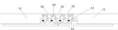
- FIG. 1is an exploded perspective view of a hinge structure of a foldable display device according to the present invention.
- FIG. 2Ais an enlarged perspective view of portion A of FIG. 1.
- Figure 2bis a perspective view of the assembled state in which the male and female joints are excluded in Figure 2a.
- FIG. 3is a plan view from above of a hinge structure of a foldable display device according to the present invention.
- FIG. 4is a bottom view of the hinge structure of the foldable display device according to the present invention.
- FIG. 5is a side view of the hinge structure in a side view when the foldable display device according to the present invention is deployed;
- FIG. 6is a side view as viewed from the side folded in the hinge structure of the foldable display device according to the present invention.
- FIG. 7is a side view of the joint support link portion inside the hinge structure in a side view when the foldable display device according to the present invention is deployed;
- FIG 8is a side view showing a folded state of a joint support link portion inside a hinge structure of the foldable display device according to the present invention.
- FIG. 9is a side view of the central link portion in the hinge structure in a foldable state according to the present invention.
- FIG. 10is a side view of a folded state of a central link portion in a hinge structure of the foldable display device according to the present invention.
- FIG. 11is a side cross-sectional view of a joint link portion connecting each joint in a hinge structure in a state where the foldable display device according to the present invention is deployed;
- FIG. 12is a side cross-sectional view of the joint link portion connecting each joint in a folded state of the hinge structure of the foldable display device according to the present invention and a perspective view of the joint link of each joint.
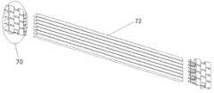
- FIG. 13is a perspective view of a state in which each joint is manufactured by insert injection in the hinge structure of the foldable display device according to the present invention.
- each jointis manufactured by insert injection in the hinge structure of the foldable display device according to the present invention.
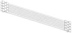
- FIG. 15is a cutaway side cross-sectional view of a portion produced by insert injection in the joint portion of the hinge structure of the foldable display device according to the present invention.
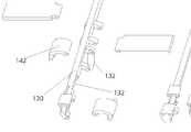
- FIG. 16is a perspective view of an embodiment in which the center connection link is modified in the foldable display device according to the present invention.
- FIG. 17is an enlarged perspective view of a portion B of FIG. 16.
- FIG. 18is a perspective view of the assembled state in which the male and female joints are removed from FIG. 16.
- FIG. 19is a bottom view of a hinge structure of a foldable display device according to a modified embodiment of the present invention, viewed from below.
- FIG. 20is a diagram illustrating a center connection link inside a hinge structure of a foldable display device according to a modified embodiment of the present invention.
- FIG. 21is a perspective view of another method of manufacturing each of the joint bodies coupled to the joints in the hinge structure of the foldable display device shown in FIGS. 13 to 13.
- FIG. 22is a perspective view of a joint body installed on each shaft in FIG. 21.
- Figure 23is a perspective view of a state in which the joint body portion is installed by insert injection into the shaft according to the present invention.
- FIG. 24is an exploded perspective view illustrating a structure in which the joint units and the body part are connected to each other by an insert method in the hinge structure of the foldable display device according to the present invention.
- FIG. 25is a perspective view illustrating a joint unit attaching part for connecting joint units to each other in a hinge structure of a foldable display device according to an embodiment of the present invention in a state in which joint units are disposed at a central portion connecting a pair of body parts to each other.
- Figure 26is a perspective view of a state in which the joint unit attachment portion and the side support means are all installed according to the present invention.
- FIG. 27is a perspective view of the joint unit attaching part and the side support means in a state in which the folding structure of the foldable display device according to the present invention is folded in an outfolding manner.
- FIG. 28is a perspective view of all the separated components illustrated in FIG. 27 installed.
- 29is an exploded perspective view of another embodiment in which the joint units and the body part are connected to each other by an insert method in the hinge structure of the foldable display device according to the present invention.
- FIG. 30is a perspective view of a hinge structure of a foldable display device according to another exemplary embodiment shown in FIG. 29, viewed from below.
- FIG. 31is a perspective view of a side support means installed in the state in which the joint units are arranged in the hinge structure shown in FIG. 29.
- FIG. 32is a perspective view of the state of FIG. 31 as viewed from below.
- FIG 33is a perspective view of a joint unit attachment portion is installed with respect to the joint unit with the side support means in the hinge structure of another embodiment according to the present invention.
- FIG. 34is a perspective view of the state of FIG. 33 viewed from below.
- FIG. 34is a perspective view of the state of FIG. 33 viewed from below.
- FIG. 35is an explanatory diagram for explaining the structure of cut portions of sections A and B in the hinge structure of still another embodiment shown in FIG. 29;
- joint unit attachment portion 210joint units
- FIG. 1is an exploded perspective view of a hinge structure of a foldable display device according to the present invention.
- FIG. 2Ais an enlarged perspective view of portion A of FIG. 1.
- Figure 2bis a perspective view of the assembled state in which the male and female joints are excluded in Figure 2a.
- the center joint 30is positioned at the center, and the arm joints connected to each other left and right starting from the center joint 30 ( 60) and the joint consisting of the joint 50 is composed.
- the left and right sides of the center joint 30 of the present inventionare configured to be connected to each other in such a manner that the same number of joints 40 and 50 are pinned into the holes.
- the left and right arm joints 60are connected to the body parts 10 and 12 on the left and right sides in such a manner that pins and the like are inserted into the holes.
- the joint support link 44 and the center connection link 42are configured to be connected to the center connection part 32 and the support connection part 34.
- One end of the center link link 42 of the present inventionis rotatably connected to the center connecting portion 32 of the center joint 30, the other end is rotatably connected to the connecting portion 22 of the sliding plate 20.
- joint support link 44 of the present inventionis rotatably connected to the protruding connecting portion 34, and is fitted along the sliding grooves 52 and 62 below the respective joint 50 and the arm joint 60, respectively. It slides on the support part 18 of the sliding plate 12.
- 3is a plan view from above of a hinge structure of a foldable display device according to the present invention.
- 4is a bottom view of the hinge structure of the foldable display device according to the present invention.
- a plurality of joints 30, 50, and 60are connected to each other at a portion where a pair of opposing body parts 10 and 12 contact each other.
- An articulated portionis installed.
- the flexible display panel displaying a video, an image, and the likeis closely attached to the joint part configured to connect the body parts 10 and 12 and the plurality of joints 30, 50 and 60 of FIG. 3 to each other.
- 5is a side view of the hinge structure in a side view when the foldable display device according to the present invention is deployed; 6 is a side view as viewed from the side folded in the hinge structure of the foldable display device according to the present invention.
- the joint support link 44installed in the hinge structure of the foldable display device according to the present invention when the hinge structure of the foldable display device according to the present invention is folded or unfolded.
- the sliding grooves 52 and 62 of the male joint 50 and the female joint 60are moved.
- the joint support 44when the body parts 10 and 12 are folded or unfolded, the respective joint 50 and the arm joint 60 are supported by the joint support 44. That is, when the body parts 10 and 12 are folded, the joint part is easy to maintain a circular shape, and when it is unfolded, the upper part of the joint part is unfolded while maintaining a flat shape as a whole.
- FIG. 9is a side view of the central link portion in the hinge structure in a foldable state according to the present invention.
- FIG. 10is a side view of a folded state of a central link portion in a hinge structure of the foldable display device according to the present invention.
- the center connection link 42 installed in the hinge structure of the foldable display device according to the present inventionis connected to the center joint 30 so as to rotate, and each center joint 30 is connected to the center joint 30. It is connected so that it may rotate with the connection part 22 of the left body part 10 or the right body part 12.
- the joint 50 and the arm joint 60which are connected to each other, the projection 53 and the projection guide groove 63 which can be moved by the projection is configured.
- the protrusions 53 of each of the male joints 50 according to the present inventionare configured to be fitted into the protrusion guide grooves 53 of the respective arm joints 60, the pair of body portions 10 and 12, as shown in FIG.
- the body parts 10 and 12 and the joint partWhen is unfolded, the body parts 10 and 12 and the joint part can be completely leveled, thereby preventing damage to the flexible display panel provided on the body parts 10 and 12 and the joint part. That is, the body portions 10 and 12 of the present invention can be prevented from being bent out of the horizontal state.
- FIG. 13is a perspective view of a state in which each joint is manufactured by an insert method in the hinge structure of the foldable display device according to the present invention.
- FIG. 14is a perspective view of each joint of the joint part manufactured by the insert method in the hinge structure of the foldable display device according to the present invention.
- the middle partis manufactured by an insert method except for the parts connected to each other by pins inserted at the left and right sides of the joint part. can do.
- Joint connection portion 70 of the present inventionis made of a metal material and the joint body portion 72 of the center portion can be made of a plastic material by the insert injection method. This can reduce the overall weight of the hinge structure of the foldable display device, it is possible to prevent the water penetrates between the joint and the joint constituting the joint portion. In addition, it can also be manufactured by inserting with different materials such as metal and plastic rubber.
- the overall weight of the hinge structure of the foldable display device according to the present inventionis reduced to reduce the possibility of failure even if the user accidentally drops the foldable display device.
- FIG. 15is a cutaway side cross-sectional view of a portion manufactured by an insert method in the joint portion of the hinge structure of the foldable display device according to the present invention.
- the joint body portion 72 of the joint portion of the present inventioncan be made of a material such as plastic, rubber, or silicone by an insert method, and in the case of using a cloth, the joint body portion 72 is manufactured by ultrasonic welding. Between the joints of the body portion 72 is a structure that is connected to each other by a connecting film 75 of a material such as plastic, rubber, silicone, rubber, cloth.
- 16is a perspective view of an embodiment in which the center connection link is modified in the foldable display device according to the present invention.
- 17is an enlarged perspective view of a portion B of FIG. 16.
- 18is a perspective view of the assembled state in which the male and female joints are removed from FIG. 16.
- the center connection part 132 of the center joint 130may be modified to protrude.
- the deformed center connection link 142is rotatably connected in such a way that a pin or the like is fitted to the protruding center connection part 132.
- FIG. 19is a bottom view of a hinge structure of a foldable display device according to a modified embodiment of the present invention, viewed from below.
- the center connecting link 142is almost invisible when the hinge structure of the foldable display device according to the modified embodiment of the present invention is viewed from below.
- FIG. 20is a diagram illustrating a center connection link inside a hinge structure of a foldable display device according to a modified embodiment of the present invention.
- the central link link 142 of the present inventionwhen the central link link 142 of the present invention is connected to the central joint 130, the central link link 142 is rotatably connected to the central connection portion 132 protruding from the modified central joint 130. have.
- the figureshows a shape in which the center connection link 142 is disposed inside the hinge structure in a state where the pair of body portions 10 and 12 are unfolded, and (b) the pair of body portions 10 and 12 are shown in the figure.
- the center connecting link 142 inside the hinge structureis arranged in a state in which) are folded to each other.
- (C)is a side cross-sectional view of the central joint link 142 is installed in the modified central joint 132.
- FIG. 21is a perspective view of another method of manufacturing each of the joint bodies coupled to the joints in the hinge structure of the foldable display device shown in FIGS. 13 to 13.
- FIG. 22is a perspective view of a joint body installed on each shaft in FIG. 21.
- each joint unit of the pair of joint portions 70is formed in each joint unit of the pair of joint portions 70 according to the present invention.
- each of the joint body portions 72is formed such that a hole passes therethrough so that each shaft 73 can pass therethrough.
- Each shaft 73is fitted so as to penetrate each joint body 72 according to the present invention, and both ends of the shaft 73 are fitted and fixed in the holes of the respective joints 70.
- Figure 23is a perspective view of a state in which the joint body portion is installed by insert injection into the shaft according to the present invention.
- the joint body portion 72may be installed in an insert manner after the joint portions 70 are fitted to both ends of each shaft 73 according to the present invention.
- Joint body portion 72 in accordance with the present inventioncan be manufactured using a material such as plastic, rubber, silicone, PP in the insert method or insert injection method.
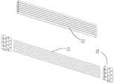
- FIG. 24is an exploded perspective view illustrating a structure in which the joint units and the body part are connected to each other by an insert method in the hinge structure of the foldable display device according to the present invention.
- the joint units 210 and the body partsare connected to each other by an insert method, and face the body parts 10 and 12 facing each other.
- Grooves 212are formed in the center, and a plurality of joint units 210 are disposed in the center portion, and the plurality of joint units 210 of the present invention have side portions at both ends of the side support means 218. Is connected to be fixed to each other by, the inner side portion has a configuration that is fixed to each other by the joint unit attachment portion (200).
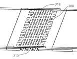
- FIG. 25is a perspective view illustrating a joint unit attaching part for connecting joint units to each other in a hinge structure of a foldable display device according to an embodiment of the present invention in a state in which joint units are disposed at a central portion connecting a pair of body parts to each other.
- the joint unit attachment part 200includes the plurality of joint units 210 in a state where a plurality of joint units 210 are disposed at a portion connecting the pair of body parts 10 and 12 to each other.
- the joint unit attachment part 200is installed to be connected to each other.
- Joint unit attachment portion 200 according to the present inventioncan be installed by the insert method or the insert injection method.
- Figure 26is a perspective view of a state in which the joint unit attachment portion and the side support means are all installed according to the present invention.
- the joint unit attachment part 200is installed such that a plurality of joint units 210 are connected to each other by an insert method or an insert injection method without being separated from each other, and the side support means of the present invention. 218 is provided to connect and fix both side upper ends of the plurality of joint units 210 to each other.
- the side support means 218 according to the present inventioncan be installed by the insert method or the insert injection method.
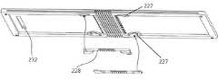
- FIG. 27is a perspective view of the joint unit attaching part and the side support means in a state in which the folding structure of the foldable display device according to the present invention is folded in an outfolding manner.
- FIG. 28is a perspective view of all the separated components illustrated in FIG. 27 installed.
- the pair of body parts 10 and 12are folded together in an outfolding manner in which a flexible display panel is installed on an outer surface thereof.
- Joint units 210which are connected to each other so as to be bent are configured to be connected to each other by the joint unit attachment portion 200 and the side connection means 218.
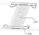
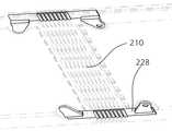
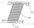
- FIG. 29is an exploded perspective view of another embodiment in which the joint units and the body part are connected to each other by an insert method in the hinge structure of the foldable display device according to the present invention.
- FIG. 30is a perspective view of a hinge structure of a foldable display device according to another exemplary embodiment shown in FIG. 29, viewed from below.
- a plurality of joint units 210are disposed between the pair of body portions 10 and 12 so that the pair of body portions 10 and 12 are bonded to each other, and formed on the rear surface of the body portion.
- the side connecting means 228is configured such that the pair of body parts 10 and 12 and the plurality of joint units 210 are connected to each other by injecting an insert material such as rubber, silicone, or plastic through the insert material inlet 227. do.
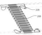
- FIG. 31is a perspective view of a side support means installed in the state in which the joint units are arranged in the hinge structure shown in FIG. 29.
- 32is a perspective view of the state of FIG. 31 as viewed from below.
- side connection means 228formed by injecting an insert material such as rubber, silicon, plastic, etc. through an insert material injection hole 227 formed on the rear surface of the body parts 10 and 12 according to the present invention.
- the pair of body parts 10 and 12 and the plurality of joint units 210are connected to each other.
- FIG. 33is a perspective view of a joint unit attachment portion is installed with respect to the joint unit with the side support means in the hinge structure of another embodiment according to the present invention.
- FIG. 34is a perspective view of the state of FIG. 33 viewed from below.
- Joint unit attachment portion 200is also made of a material such as rubber serves to support the lower end of the flexible display panel.
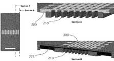
- FIG. 35is an explanatory view for explaining the structure of the cut portions of sections A and B in the hinge structure having the double injection structure of still another embodiment shown in FIG. 29;
- the joint unit attaching part 200 manufactured by the insert method with a material such as rubber or siliconeis fixed to the plurality of joint units 210, and in the section B, the joint unit is fixed.
- the body parts 10 and 12 adjacent to both sides of the 210are injected with insert materials such as rubber, silicone, and plastic to connect the body parts 10 and 12 and the side parts of the plurality of joint units 210 to each other.
- the side connecting means 228is provided.
- the side connection means 228 of the present inventionmay be composed of thermoplastic polyurethane (TPU).
- Joint units 210 of the present inventionmay be composed of duralumin.
Landscapes
- Engineering & Computer Science (AREA)
- Theoretical Computer Science (AREA)
- Physics & Mathematics (AREA)
- General Physics & Mathematics (AREA)
- Human Computer Interaction (AREA)
- General Engineering & Computer Science (AREA)
- Devices For Indicating Variable Information By Combining Individual Elements (AREA)
Abstract
Description
Translated fromKorean본 발명은 폴더블 디스플레이 장치의 힌지구조에 관한 것으로, 더욱 자세히 설명하면, 2개 바디부로 구성되고, 가운데 부분에는 다수개의 관절로 구성된 관절부로 연결된 구조를 가지는 디스플레이 표시장치를 제작하는데 있어서, 관절부의 중심관절을 중심으로 좌우의 바디부가 접히거나 펼쳐질 수 있도록 구성되고, 플렉서블한 디스플레이 패널이 좌우의 바디부가 접혀진 상태에서 외측표면 (바디부의 내 외측면의 일부분에만 설치도 가능함) 에 설치될 수 있는 디스플레이 표시장치를 구현할 수 있는 폴더블 디스플레이 장치의 힌지구조에 관한 것이다.The present invention relates to a hinge structure of a foldable display device. More specifically, the present invention relates to a hinge structure of a foldable display device. The present invention relates to a hinge structure of a foldable display device. The display is configured so that the left and right body parts can be folded or unfolded around the center joint, and the flexible display panel can be installed on the outer surface (may be installed only on a part of the inner and outer surfaces of the body part) while the left and right body parts are folded. It relates to a hinge structure of a foldable display device that can implement a display device.
일반적으로 이동 단말기에서 디스플레이 모듈은 이동 단말기에서 처리되는 정보를 표시한다. 예를 들어 이동 단말기가 통화 모드인 경우 통화와 관련된 UI(User Interface) 또는 GUI(Graphic User Interface)를 표시한다.In general, a display module in a mobile terminal displays information processed in a mobile terminal. For example, when the mobile terminal is in a call mode, a user interface (UI) or a graphic user interface (GUI) related to a call is displayed.
디스플레이 모듈은 액정 디스플레이(liquid crystal display), 유기 발광 다이오드(organic light-emitting diode), 플렉시블 디스플레이(flexible display), 등으로 구성될 수 있다.The display module may be composed of a liquid crystal display, an organic light-emitting diode, a flexible display, and the like.
그 중에서 플렉시블 디스플레이(flexible display) 는 모양을 마음대로 변형할 수 있다는 장점 때문에 현재 그 연구가 본격화되고 있다. 따라서, 플렉시블 디스플레이가 이동 단말기에 사용될 때 그 사용 형태 및 그 보호 방법에 대하여 기술할 필요성이 대두되고 있는 실정이다.Among them, the research of the flexible display has been in full swing because of the advantage that the shape can be freely modified. Therefore, when a flexible display is used in a mobile terminal, there is a need to describe its usage form and its protection method.
본 발명에 따른 연성디스플레이 패널이 설치되는 모바일 통신장치용 힌지구조와 유사한 특허문헌으로는 공개번호 10-2015-0096827, (발명의 명칭 힌지장치 및 이를 구비하는 폴더블 디스플레이 장치) 가 있다.Patent documents similar to the hinge structure for a mobile communication device in which the flexible display panel according to the present invention are provided are Publication No. 10-2015-0096827, (Name hinge device of the invention and a foldable display device having the same).
본 발명은 본 발명은 종래의 스마트폰을 개량한 것으로, 종래의 스마트폰의 디스플레이 화면보다 2배 이상의 넓은 디스플레이 화면면적을 가지고, 사용자가 휴대를 위해서는 스마트폰의 가운데 부분 (또는 다른 접혀지는 부분) 이 접혀지는 구성을 하도록 스마트폰의 가운데 부분에 다수개의 연결된 관절의 다관절 힌지부를 설치하고, 스마트폰의 화면을 접거나 펼치는 경우에 다관절 힌지부가 안정적으로 지지될 수 있는 폴더블 디스플레이 장치의 힌지구조를 제공하는 것을 목적으로 한다.The present invention is an improvement of the conventional smartphone, and has a display screen area more than twice as large as the display screen of the conventional smartphone, the user to carry the center portion of the smartphone (or other folded portion) The hinge of the foldable display device in which the articulated hinge portion of a plurality of connected joints is installed in the center portion of the smart phone so as to be folded, and the articulated hinge portion can be stably supported when the screen of the smart phone is folded or unfolded. The purpose is to provide a structure.
상기의 목적을 달성하기 위하여, 본 발명에 따른 폴더블 디스플레이 장치의 힌지구조는, 가운데 부분에 중심관절 (30) 이 위치하고, 상기 중심관절 (30) 을 시작으로 좌우로 서로 연결된 암관절 (60) 과 숫관절 (50) 로 구성되는 관절부를 구성하고, 상기 중심관절 (30) 의 좌우측에는 서로 동일한 개수의 관절들 (40, 50) 이 핀 등이 구멍에 끼워지는 방식으로 서로 연결되고, 상기 중심관절 (30) 에는 관절지지링크 (44) 와 중심연결링크 (42) 가 회전할 수 있도록 연결되는 중심연결부 (32) 와 지지연결부 (34) 가 구성되고, 상기 중심연결링크 (42) 는 일단이 중심관절 (30) 의 상기 중심연결부 (32) 와 회전가능하도록 연결되고, 타단은 슬라이딩판 (20) 의 연결부 (22) 에 회전가능하도록 연결되고, 상기 관절지지링크 (44) 는 일단은 돌출연결부 (34) 에 회전가능하도록 연결되고, 상기 각각의 숫관절 (50) 과 암관절 (60) 아래의 슬라이딩홈 (52, 62) 을 따라 끼워지고 슬라이딩 판 (12) 의 지지부 (18) 위에서 슬라이딩 하는 것을 특징으로 하고,In order to achieve the above object, the hinge structure of the foldable display device according to the present invention, the
상기 관절지지링크 (44) 는 상기 힌지구조가 접혀지거나 펼쳐지는 동작을 할 때, 상기 각각의 숫관절 (50) 과 암관절 (60) 의 슬라이딩홈 (52, 62) 을 따라 움직이는 것을 특징으로 하고, 상기 서로 연결된 숫관절 (50) 과 암관절 (60) 에는 각각 돌기 (53) 와 돌기가 끼워져 움질일 수 있는 돌기가이드홈 (63) 이 구성되는 것을 특징으로 하고, 상기 관절부는 좌우 측면에는 관절연결부 (70) 로 구성되고, 가운데 부분은 관절바디부 (72) 로 구성되고, 상기 관절연결부 (70) 는 금속재질로 제작을 하고 가운데 부분인 상기 관절바디부 (72) 는 인서트사출방식에 의해 플라스틱 재질로 제작하는 것을 특징으로 한다.The
또한, 본 발명에 따른 폴더블 디스플레이 장치의 힌지구조는, 다수개의 관절유닛들 (210) 이 한쌍의 바디부 (10, 12) 가 접합하도록 한쌍의 바디부 (10, 12) 의 사이에 배치되고, 상기 바디부의 배면에 형성된 인서트물질 주입구 (227) 를 통하여 고무, 실리콘, 플라스틱 등의 인서트물질을 주입하여 형성된 측부연결수단 (228) 이 한쌍의 바디부 (10, 12) 와 다수개의 관절유닛들 (210) 이 서로 연결되도록 구성하고, 상기 측부연결수단 (228) 이 설치된 후에 상기 관절유닛부착부 (200) 가 각각의 관절유닛들 (210) 및 상기 바디부 (10, 12) 가 서로 연결되도록 인서트방식에 의해 제작이 되는 것을 특징으로 한다.In addition, the hinge structure of the foldable display device according to the present invention is arranged between the pair of
본 발명에 따른 폴더블 디스플레이 장치의 힌지구조는, 좌우의 바디부가 접히는 기준점으로 관절부의 중심에 중심관절을 두고, 상기 중심관절을 중심으로 바디부가 좌우로 접히도록 구성하고, 상기 중심관절과 바디부를 중심연결링크와 관절지지링크로 연결하여 좌우의 바디부가 접히거나 펼치질때 가운데 관절부가 정확하게 원형을 유지하면서 접혀지게 구성되는 효과가 있다.The hinge structure of the foldable display device according to the present invention includes a central joint at the center of the joint as a reference point at which the left and right body parts are folded, and is configured to fold the left and right body parts around the center joint, and the center joint and the body part. When the left and right body parts are folded or unfolded by connecting with the center connection link and the joint support link, the center joint part has an effect of being folded while maintaining a precisely circular shape.
또한, 본 발명에서 서로 연결된 숫관절과 암관절에는 각각 돌기와 돌기가 끼워져 움질일 수 있는 돌기가이드홈이 구성되어 있다. 본 발명의 돌기가이드홈은 스토퍼역할을 수행하며 관절의 각도를 조절하도록 구성되어 있다.In addition, in the present invention, each of the male and female joints connected to each other is formed with a projection guide groove which can be fitted with projections and projections. The protrusion guide groove of the present invention serves as a stopper and is configured to adjust the angle of the joint.
본 발명에 따른 각각의 숫관절의 돌기가 각각의 암관절의 돌기가이드홈에 끼워져 움직이는 구성이기 때문에 한쌍의 바디부가 펼쳐졌을때, 바디부 및 관절부가 완전하게 수평을 유지할 수 있게 되어, 바디부 및 관절부 위에 설치된 플렉서블한 디스플레이 패널이 손상이 되는 것이 방지될 수 있다.Since each projection of the male joint according to the present invention is configured to be inserted into the projection guide groove of each arm joint, when the pair of body parts are unfolded, the body part and the joint part can be completely leveled, the body part and Damage to the flexible display panel provided over the joint portion can be prevented.
또한, 폴더블 디스플레이 장치의 힌지구조에서 관절부를 제작하는데 있어서, 관절부의 좌측과 우측의 서로 핀 등이 끼워져서 서로 연결되는 부분을 제외하고 가운데 부분은 인서트 사출방식으로 제작을 할 수 있다. (실리콘, 고무 등의 다른 재질의 인서트구조로 제작을 할 수도 있다. 직물도 가능함) 이렇게 되면 폴더블 디스플레이 장치의 힌지구조의 전체적인 무게를 줄일 수 있고, 관절부를 구성하는 관절과 관절 사이로 물이 스며드는 것을 방지할 수 있는 효과가 있다. 또한, 본 발명에 따른 폴더블 디스플레이 장치의 힌지구조의 전체적인 무게가 줄어즐게 되어 사용자가 폴더블 디스플레이 장치를 실수로 떨어트리게 되더라도 고장의 가능성이 줄어들게 된다.In addition, in manufacturing the joint part in the hinge structure of the foldable display device, the center part may be manufactured by an insert injection method except for a part in which pins and the like are connected to each other at the left and right sides of the joint part. This can reduce the overall weight of the hinged structure of the foldable display device and allow water to penetrate between the joints and joints that make up the joints. There is an effect that can be prevented. In addition, the overall weight of the hinge structure of the foldable display device according to the present invention is reduced to reduce the possibility of failure even if the user accidentally drops the foldable display device.
도 1 은 본 발명에 따른 폴더블 디스플레이 장치의 힌지구조의 분해 사시도이다.1 is an exploded perspective view of a hinge structure of a foldable display device according to the present invention.
도 2a 는 도 1 의 A 부분에 대한 확대된 사시도이다. 도 2b 는 도 2a 에서 숫관절과 암관절이 제외된 상태에서 조립된 상태의 사시도이다.FIG. 2A is an enlarged perspective view of portion A of FIG. 1. Figure 2b is a perspective view of the assembled state in which the male and female joints are excluded in Figure 2a.
도 3 은 본 발명에 따른 폴더블 디스플레이 장치의 힌지구조를 위에서 바라본 평면도이다.3 is a plan view from above of a hinge structure of a foldable display device according to the present invention;
도 4 는 본 발명에 따른 폴더블 디스플레이 장치의 힌지구조를 아래에서 바라본 저면도이다.4 is a bottom view of the hinge structure of the foldable display device according to the present invention.
도 5 는 본 발명에 따른 폴더블 디스플레이 장치가 펼쳐진 상태에서 힌지구조를 측면에서 바라본 측면도이다.5 is a side view of the hinge structure in a side view when the foldable display device according to the present invention is deployed;
도 6 은 본 발명에 따른 폴더블 디스플레이 장치의 힌지구조에 접혀진 모습을 측면에서 바라본 측면도이다.6 is a side view as viewed from the side folded in the hinge structure of the foldable display device according to the present invention.
도 7 는 본 발명에 따른 폴더블 디스플레이 장치가 펼쳐진 상태에서 힌지구조 내부의 관절지지링크 부분을 측면에서 바라본 측면도이다.7 is a side view of the joint support link portion inside the hinge structure in a side view when the foldable display device according to the present invention is deployed;
도 8 은 본 발명에 따른 폴더블 디스플레이 장치의 힌지구조 내부의 관절지지링크 부분의 접혀진 모습을 측면에서 바라본 측면도이다.8 is a side view showing a folded state of a joint support link portion inside a hinge structure of the foldable display device according to the present invention.
도 9 는 본 발명에 따른 폴더블 디스플레이 장치가 펼쳐진 상태에서 힌지구조 내부의 중심연결링크 부분을 측면에서 바라본 측면도이다.FIG. 9 is a side view of the central link portion in the hinge structure in a foldable state according to the present invention.
도 10 은 본 발명에 따른 폴더블 디스플레이 장치의 힌지구조 내부의 중심연결링크 부분의 접혀진 모습을 측면에서 바라본 측면도이다.FIG. 10 is a side view of a folded state of a central link portion in a hinge structure of the foldable display device according to the present invention.
도 11 는 본 발명에 따른 폴더블 디스플레이 장치가 펼쳐진 상태에서 힌지구조에서 각각의 관절을 연결하는 관절연결링크 부분을 측면에서 바라본 측단면도이다.FIG. 11 is a side cross-sectional view of a joint link portion connecting each joint in a hinge structure in a state where the foldable display device according to the present invention is deployed;
도 12 은 본 발명에 따른 폴더블 디스플레이 장치의 힌지구조가 접혀진 상태에서 각각의 관절을 연결하는 관절연결링크 부분을 측면에서 바라본 측단면도와 각각의 관절의 연결링크의 사시도이다.12 is a side cross-sectional view of the joint link portion connecting each joint in a folded state of the hinge structure of the foldable display device according to the present invention and a perspective view of the joint link of each joint.
도 13 은 본 발명에 따른 폴더블 디스플레이 장치의 힌지구조에서 관절부의 각각의 관절을 인서트사출에 의해 제작하는 모습의 사시도이다.FIG. 13 is a perspective view of a state in which each joint is manufactured by insert injection in the hinge structure of the foldable display device according to the present invention. FIG.
도 14 는 본 발명에 따른 폴더블 디스플레이 장치의 힌지구조에서 관절부의 각각의 관절이 인서트사출에 의해 제작된 모습의 사시도이다.14 is a perspective view of a state in which each joint is manufactured by insert injection in the hinge structure of the foldable display device according to the present invention.
도 15 는 본 발명에 따른 폴더블 디스플레이 장치의 힌지구조의 관절부에서 인서트사출에 의해 제작된 부분의 절단된 측단면도이다.15 is a cutaway side cross-sectional view of a portion produced by insert injection in the joint portion of the hinge structure of the foldable display device according to the present invention.
도 16 은 본 발명에 따른 폴더블 디스플레이 장치에서 중심연결링크가 변형된 실시예의 사시도이다.16 is a perspective view of an embodiment in which the center connection link is modified in the foldable display device according to the present invention.
도 17 은 도 16 의 B 부분의 확대 사시도이다.17 is an enlarged perspective view of a portion B of FIG. 16.
도 18 은 도 16 에서 숫관절과 암관절이 제외된 상태에서 조립된 상태의 사시도이다.18 is a perspective view of the assembled state in which the male and female joints are removed from FIG. 16.
도 19 는 본 발명의 변형된 실시예에 따른 폴더블 디스플레이 장치의 힌지구조를 아래에서 바라본 저면도이다.19 is a bottom view of a hinge structure of a foldable display device according to a modified embodiment of the present invention, viewed from below.
도 20 은 본 발명의 변형된 실시예에 따른 폴더블 디스플레이 장치의 힌지구조의 내부의 중심연결링크를 설명하기 위한 도면들이다.FIG. 20 is a diagram illustrating a center connection link inside a hinge structure of a foldable display device according to a modified embodiment of the present invention.
도 21 은 도 13 내지 도 13 에 도시된 본 발명에 따른 폴더블 디스플레이 장치의 힌지구조에서 관절부와 결합하는 각각의 관절바디부를 제작하는 다른 방법의 사시도이다.FIG. 21 is a perspective view of another method of manufacturing each of the joint bodies coupled to the joints in the hinge structure of the foldable display device shown in FIGS. 13 to 13.
도 22 는 도 21 에서 각각의 샤프트에 관절바디부가 설치된 모습의 사시도이다.FIG. 22 is a perspective view of a joint body installed on each shaft in FIG. 21.
도 23 은 본 발명에 따른 샤프트에 관절바디부가 인서트사출에 의해 설치된 모습의 사시도이다.Figure 23 is a perspective view of a state in which the joint body portion is installed by insert injection into the shaft according to the present invention.
도 24 는 본 발명에 따른 폴더블 디스플레이 장치의 힌지구조에서 관절유닛들과 바디부를 인서트방식에 의해 서로 연결하는 구성의 분해사시도이다.24 is an exploded perspective view illustrating a structure in which the joint units and the body part are connected to each other by an insert method in the hinge structure of the foldable display device according to the present invention.
도 25 는 본 발명에 따른 폴더블 디스플레이 장치의 힌지구조에서 관절유닛들이 한쌍의 바디부를 서로 연결하는 중앙부분에 배치된 상태에서 관절유닛들을 서로 연결하게 하는 관절유닛부착부를 설치하는 모습의 사시도이다.FIG. 25 is a perspective view illustrating a joint unit attaching part for connecting joint units to each other in a hinge structure of a foldable display device according to an embodiment of the present invention in a state in which joint units are disposed at a central portion connecting a pair of body parts to each other.
도 26 은 본 발명에 따른 관절유닛부착부와 측부지지수단이 전부 설치된 모습의 사시도이다.Figure 26 is a perspective view of a state in which the joint unit attachment portion and the side support means are all installed according to the present invention.
도 27 은 본 발명에 따른 폴더블 디스플레이 장치의 힌지구조에서 아웃폴딩방식으로 접혀진 상태에서 관절유닛부착부와 측부지지수단이 분리된 모습의 사시도이다.27 is a perspective view of the joint unit attaching part and the side support means in a state in which the folding structure of the foldable display device according to the present invention is folded in an outfolding manner.
도 28 은 도 27 에 도시된 분리된 구성요소들이 모두 설치된 모습의 사시도이다.FIG. 28 is a perspective view of all the separated components illustrated in FIG. 27 installed.
도 29 는 본 발명에 따른 폴더블 디스플레이 장치의 힌지구조에서 관절유닛들과 바디부를 인서트방식에 의해 서로 연결하는 또 다른 실시예의 분해사시도이다.29 is an exploded perspective view of another embodiment in which the joint units and the body part are connected to each other by an insert method in the hinge structure of the foldable display device according to the present invention.
도 30 은 도 29 에 도시된 다른 실시예에 따른 폴더블 디스플레이 장치의 힌지구조를 아래에서 바라본 모습의 사시도이다.FIG. 30 is a perspective view of a hinge structure of a foldable display device according to another exemplary embodiment shown in FIG. 29, viewed from below.
도 31 은 도 29 에 도시된 힌지구조에서 관절유닛들이 배치된 상태에서 측부지지수단이 설치된 모습의 사시도이다.FIG. 31 is a perspective view of a side support means installed in the state in which the joint units are arranged in the hinge structure shown in FIG. 29.
도 32 는 도 31 의 상태를 아래에서 바라본 사시도이다.32 is a perspective view of the state of FIG. 31 as viewed from below.
도 33 은 본 발명에 따른 다른 실시예의 힌지구조에서 측부지지수단이 설치된 관절유닛들에 대해 관절유닛부착부가 설치된 모습의 사시도이다.33 is a perspective view of a joint unit attachment portion is installed with respect to the joint unit with the side support means in the hinge structure of another embodiment according to the present invention.
도 34 는 도 33 의 상태를 아래에서 바라본 사시도이다.FIG. 34 is a perspective view of the state of FIG. 33 viewed from below. FIG.
도 35 는 도 29 에 도시된 또 다른 실시예의 힌지구조에서 섹션 A 와 섹션 B 의 절단된 부분의 구조를 설명하는 설명도이다.FIG. 35 is an explanatory diagram for explaining the structure of cut portions of sections A and B in the hinge structure of still another embodiment shown in FIG. 29; FIG.
**도면의 주요부분에 대한 부호의 설명**** Description of the symbols for the main parts of the drawings **
10, 12: 바디부200: 관절유닛부착부210: 관절유닛들10, 12: body portion 200: joint unit attachment portion 210: joint units
218: 측부지지수단227: 인서트물질주입구228: 측부연결수단218: side support means 227: insert material inlet 228: side connection means
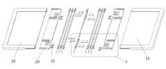
도 1 은 본 발명에 따른 폴더블 디스플레이 장치의 힌지구조의 분해 사시도이다. 도 2a 는 도 1 의 A 부분에 대한 확대된 사시도이다. 도 2b 는 도 2a 에서 숫관절과 암관절이 제외된 상태에서 조립된 상태의 사시도이다.1 is an exploded perspective view of a hinge structure of a foldable display device according to the present invention. FIG. 2A is an enlarged perspective view of portion A of FIG. 1. Figure 2b is a perspective view of the assembled state in which the male and female joints are excluded in Figure 2a.
도 1, 도 2a 및 도 2b 를 참조하면, 본 발명에 따른 폴더블 디스플레이 장치의 힌지구조는 가운데 부분에 중심관절 (30) 이 위치하고, 중심관절 (30) 을 시작으로 좌우로 서로 연결된 암관절 (60) 과 숫관절 (50) 로 구성되는 관절부를 구성한다.1, 2A and 2B, in the hinge structure of the foldable display device according to the present invention, the center joint 30 is positioned at the center, and the arm joints connected to each other left and right starting from the center joint 30 ( 60) and the joint consisting of the joint 50 is composed.
본 발명의 중심관절 (30) 의 좌우측에는 서로 동일한 갯수의 관절들 (40, 50) 이 핀 등이 구멍에 끼워지는 방식으로 서로 연결되게 구성된다. 맨 좌측과 맨 우측의 암관절 (60) 은 좌우측의 바디부 (10, 12) 와도 서로 회전할 수 있도록 핀 등이 구멍에 끼워지는 방식으로 연결된다.The left and right sides of the center joint 30 of the present invention are configured to be connected to each other in such a manner that the same number of
본 발명의 중심관절 (30) 에는 관절지지링크 (44) 와 중심연결링크 (42) 가 회전할 수 있도록 연결되는 중심연결부 (32) 와 지지연결부 (34) 가 구성되어 있다.In the central joint 30 of the present invention, the
본 발명의 중심연결링크 (42) 는 일단이 중심관절 (30) 의 중심연결부 (32) 와 회전가능하도록 연결되고, 타단은 슬라이딩판 (20) 의 연결부 (22) 에 회전가능하도록 연결된다.One end of the
본 발명의 관절지지링크 (44) 는 일단은 돌출연결부 (34) 에 회전가능하도록 연결되고, 각각의 숫관절 (50) 과 암관절 (60) 아래의 슬라이딩홈 (52, 62) 을 따라 끼워지고 슬라이딩 판 (12) 의 지지부 (18) 위에서 슬라이딩 한다.One end of the
도 3 은 본 발명에 따른 폴더블 디스플레이 장치의 힌지구조를 위에서 바라본 평면도이다. 도 4 는 본 발명에 따른 폴더블 디스플레이 장치의 힌지구조를 아래에서 바라본 저면도이다.3 is a plan view from above of a hinge structure of a foldable display device according to the present invention; 4 is a bottom view of the hinge structure of the foldable display device according to the present invention.
도 3 및 도 4 를 참조하면, 본 발명에 따른 폴더블 디스플레이 장치의 힌지구조는 한쌍의 마주보는 바디부 (10, 12) 가 서로 접하는 부분에 다수개의 관절 (30, 50, 60) 이 서로 연결되도록 구성된 관절부가 설치되어 있다.3 and 4, in the hinge structure of the foldable display device according to the present invention, a plurality of
동영상, 이미지 등이 표시되는 플렉서블한 디스플레이 패널은 도 3 의 바디부 (10, 12) 와 다수개의 관절 (30, 50, 60) 이 서로 연결되도록 구성된 관절부 위에 밀착되게 설치된다.The flexible display panel displaying a video, an image, and the like is closely attached to the joint part configured to connect the
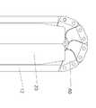
도 5 는 본 발명에 따른 폴더블 디스플레이 장치가 펼쳐진 상태에서 힌지구조를 측면에서 바라본 측면도이다. 도 6 은 본 발명에 따른 폴더블 디스플레이 장치의 힌지구조에 접혀진 모습을 측면에서 바라본 측면도이다.5 is a side view of the hinge structure in a side view when the foldable display device according to the present invention is deployed; 6 is a side view as viewed from the side folded in the hinge structure of the foldable display device according to the present invention.
도 5 및 도 6 을 참조하면, 본 발명에 따른 폴더블 디스플레이 장치를 측면에서 바라보면, 중심관절 (30) 을 중심으로 암관절 (60) 과 숫관절 (50) 이 좌우로 동일한 갯수만큼 핀 등이 구멍이 끼워지는 방식으로 서로 연결되어 있다.5 and 6, when the foldable display device according to the present invention is viewed from the side, the arm joint 60 and the male joint 50 are centered around the central joint 30, and the number of pins is equal to each other. These holes are connected to each other by fitting.
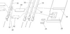
도 7 는 본 발명에 따른 폴더블 디스플레이 장치가 펼쳐진 상태에서 힌지구조 내부의 관절지지링크 부분을 측면에서 바라본 측면도이다. 도 8 은 본 발명에 따른 폴더블 디스플레이 장치의 힌지구조 내부의 관절지지링크 부분의 접혀진 모습을 측면에서 바라본 측면도이다.7 is a side view of the joint support link portion inside the hinge structure in a side view when the foldable display device according to the present invention is deployed; 8 is a side view showing a folded state of a joint support link portion inside a hinge structure of the foldable display device according to the present invention.
도 7 및 도 8 을 참조하면, 본 발명에 따른 폴더블 디스플레이 장치의 힌지구조 내부의 설치된 관절지지링크 (44) 는 본 발명에 따른 폴더블 디스플레이 장치의 힌지구조가 접혀지거나 펼쳐지는 동작을 할 때, 각각의 숫관절 (50) 과 암관절 (60) 의 슬라이딩홈 (52, 62) 을 따라 움직이게 된다.7 and 8, the
따라서, 바디부 (10, 12) 가 접혀지거나 펼쳐지는 경우에 각각의 숫관절 (50) 과 암관절 (60) 이 관절지지대 (44) 에 의해 지지를 받게 된다. 즉, 바디부 (10, 12) 가 접혀질때 관절부가 원형을 유지하기 쉽고, 펼쳐지는 경우에 관절부의상부면이 전체적으로 평평한 형상을 유지하면서 펼쳐지게 된다.Thus, when the
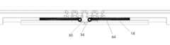
도 9 는 본 발명에 따른 폴더블 디스플레이 장치가 펼쳐진 상태에서 힌지구조 내부의 중심연결링크 부분을 측면에서 바라본 측면도이다. 도 10 은 본 발명에 따른 폴더블 디스플레이 장치의 힌지구조 내부의 중심연결링크 부분의 접혀진 모습을 측면에서 바라본 측면도이다.FIG. 9 is a side view of the central link portion in the hinge structure in a foldable state according to the present invention. FIG. 10 is a side view of a folded state of a central link portion in a hinge structure of the foldable display device according to the present invention.
도 9 및 도 10 을 참조하면, 본 발명에 따른 폴더블 디스플레이 장치의 힌지구조 내부 설치된 중심연결링크 (42) 는 중심관절 (30) 과 회전할 수 있도록 연결되어 있고, 각각의 중심관절 (30) 이 좌측 바디부 (10) 또는 우측바디부 (12) 의 연결부 (22) 와 회전할 수 있도록 연결된다.9 and 10, the
도 11 는 본 발명에 따른 폴더블 디스플레이 장치가 펼쳐진 상태에서 힌지구조에서 각각의 관절을 연결하는 관절연결링크 부분을 측면에서 바라본 측단면도이다. 도 12 은 본 발명에 따른 폴더블 디스플레이 장치의 힌지구조가 접혀진 상태에서 각각의 관절을 연결하는 관절연결링크 부분을 측면에서 바라본 측단면도와 각각의 관절의 연결링크의 사시도이다.FIG. 11 is a side cross-sectional view of a joint link portion connecting each joint in a hinge structure in a state where the foldable display device according to the present invention is deployed; 12 is a side cross-sectional view of the joint link portion connecting each joint in a folded state of the hinge structure of the foldable display device according to the present invention and a perspective view of the joint link of each joint.
도 11 및 도 12 를 참조하면, 서로 연결된 숫관절 (50) 과 암관절 (60) 에는 각각 돌기 (53) 와 돌기가 끼워져 움질일 수 있는 돌기가이드홈 (63) 이 구성되어 있다.Referring to Figures 11 and 12, the joint 50 and the arm joint 60, which are connected to each other, the
본 발명에 따른 각각의 숫관절 (50) 의 돌기 (53) 가 각각의 암관절 (60) 의 돌기가이드홈 (53) 에 끼워져 움직이는 구성이기 때문에 도 11 과 같이 한쌍의 바디부 (10, 12) 가 펼쳐졌을때, 바디부 (10, 12) 및 관절부가 완전하게 수평을 유지할 수 있게 되어, 바디부 (10, 12) 및 관절부 위에 설치된 플렉서블한 디스플레이 패널이 손상이 되는 것이 방지될 수 있다. 즉, 본 발명의 바디부 (10, 12) 가 수평한 상태를 벗어나게 구부러지는 것을 방지할 수 있다.Since the
도 13 은 본 발명에 따른 폴더블 디스플레이 장치의 힌지구조에서 관절부의 각각의 관절을 인서트방식에 의해 제작하는 모습의 사시도이다. 도 14 는 본 발명에 따른 폴더블 디스플레이 장치의 힌지구조에서 관절부의 각각의 관절이 인서트방식에 의해 제작된 모습의 사시도이다.FIG. 13 is a perspective view of a state in which each joint is manufactured by an insert method in the hinge structure of the foldable display device according to the present invention. FIG. FIG. 14 is a perspective view of each joint of the joint part manufactured by the insert method in the hinge structure of the foldable display device according to the present invention. FIG.
도 13 및 도 14 를 참조하면, 폴더블 디스플레이 장치의 힌지구조에서 관절부를 제작하는데 있어서, 관절부의 좌측과 우측의 서로 핀 등이 끼워져서 서로 연결되는 부분을 제외하고 가운데 부분은 인서트 방식으로 제작을 할 수 있다.Referring to FIGS. 13 and 14, in the hinge structure of the foldable display device, the middle part is manufactured by an insert method except for the parts connected to each other by pins inserted at the left and right sides of the joint part. can do.
본 발명의 관절연결부 (70) 는 금속재질로 제작을 하고 가운데 부분인 관절바디부 (72) 는 인서트사출방식에 의해 플라스틱 재질로 제작을 할 수 있다. 이렇게 되면 폴더블 디스플레이 장치의 힌지구조의 전체적인 무게를 줄일 수 있고, 관절부를 구성하는 관절과 관절 사이로 물이 스며드는 것을 방지할 수 있는 효과가 있다. 이외에도 금속, 플라스틱 고무 등의 서로 다른 재질로의 인서트방식으로 제작할 수도 있다.
또한, 본 발명에 따른 폴더블 디스플레이 장치의 힌지구조의 전체적인 무게가 줄어즐게 되어 사용자가 폴더블 디스플레이 장치를 실수로 떨어트리게 되더라도 고장의 가능성이 줄어들게 된다.In addition, the overall weight of the hinge structure of the foldable display device according to the present invention is reduced to reduce the possibility of failure even if the user accidentally drops the foldable display device.
도 15 는 본 발명에 따른 폴더블 디스플레이 장치의 힌지구조의 관절부에서 인서트방식에 의해 제작된 부분의 절단된 측단면도이다.15 is a cutaway side cross-sectional view of a portion manufactured by an insert method in the joint portion of the hinge structure of the foldable display device according to the present invention.
도 15 를 참조하면, 본 발명의 관절부의 관절바디부 (72) 가 인서트방식에 의해 플라스틱, 고무 또는 실리콘 등의 재질로 제작을 할 수 있고, 또한 천을 사용할 경우에는 초음파 융착으로 제작이 되고, 관절바디부 (72) 의 각각의 관절 사이가 플라스틱, 고무, 실리콘, 고무, 천과 같은 재질의 연결막 (75) 에 의해 서로 연결이 되어 있는 구조이다.Referring to Fig. 15, the
도 16 은 본 발명에 따른 폴더블 디스플레이 장치에서 중심연결링크가 변형된 실시예의 사시도이다. 도 17 은 도 16 의 B 부분의 확대 사시도이다. 도 18 은 도 16 에서 숫관절과 암관절이 제외된 상태에서 조립된 상태의 사시도이다.16 is a perspective view of an embodiment in which the center connection link is modified in the foldable display device according to the present invention. 17 is an enlarged perspective view of a portion B of FIG. 16. 18 is a perspective view of the assembled state in which the male and female joints are removed from FIG. 16.
도 16 내지 도 18 을 참조하면, 본 발명의 변형된 실시예에 따른 폴더블 디스플레이 장치에서 중심관절 (130) 의 중심연결부 (132) 가 돌출되게 구성되게 변형이 될 수 있다. 변형된 중심연결링크 (142) 가 돌출된 중심연결부 (132) 에 핀 등이 끼워지는 방식으로 회전할 수 있도록 연결된다.16 to 18, in the foldable display device according to the modified embodiment of the present invention, the
도 19 는 본 발명의 변형된 실시예에 따른 폴더블 디스플레이 장치의 힌지구조를 아래에서 바라본 저면도이다.19 is a bottom view of a hinge structure of a foldable display device according to a modified embodiment of the present invention, viewed from below.
도 19 를 참조하면, 본 발명의 변형된 실시예에 따른 폴더블 디스플레이 장치의 힌지구조를 아래에서 바라보면 중심연결링크 (142) 가 거의 보이지 않게 된다.Referring to FIG. 19, the
도 20 은 본 발명의 변형된 실시예에 따른 폴더블 디스플레이 장치의 힌지구조의 내부의 중심연결링크를 설명하기 위한 도면들이다.FIG. 20 is a diagram illustrating a center connection link inside a hinge structure of a foldable display device according to a modified embodiment of the present invention.
도 20 을 참조하면, 본 발명의 중심연결링크 (142) 가 중심관절 (130) 에 연결된 구성을 살펴보면, 변형된 중심관절 (130) 에서 반대편으로 돌출된 중심연결부 (132) 에 회전가능하도록 연결되어 있다.Referring to FIG. 20, when the
(a) 도면은 한쌍의 바디부 (10, 12) 가 펼쳐진 상태에서 힌지구조 내부의 중심연결링크 (142) 가 배치된 모양이 도시되어 있고, (b) 도면에서는 한쌍의 바디부 (10, 12) 가 서로 접혀진 상태에서 힌지구조 내부의 중심연결링크 (142) 가 배치된 모양이 도시되어 있다. (c) 도면은 변형된 중심관절 (132) 에서 중심관절링크 (142) 가 설치되어 있는 모습의 측단면도이다.(a) The figure shows a shape in which the
도 21 은 도 13 내지 도 13 에 도시된 본 발명에 따른 폴더블 디스플레이 장치의 힌지구조에서 관절부와 결합하는 각각의 관절바디부를 제작하는 다른 방법의 사시도이다. 도 22 는 도 21 에서 각각의 샤프트에 관절바디부가 설치된 모습의 사시도이다.FIG. 21 is a perspective view of another method of manufacturing each of the joint bodies coupled to the joints in the hinge structure of the foldable display device shown in FIGS. 13 to 13. FIG. 22 is a perspective view of a joint body installed on each shaft in FIG. 21.
도 21 내지 도 22 를 참조하면, 본 발명에 따른 한쌍의 관절부 (70) 의 각 관절유닛에는 샤프트 (73) 가 끼워질 수 있는 구멍이 형성되어 있다. 또한, 관절바디부 (72) 각각에는 각각의 샤프트 (73) 가 관통할 수 있도록 구멍이 관통되게 형성되어 있다.21 to 22, a hole in which the
본 발명에 따른 각각의 관절바디부 (72) 를 관통하도록 각각의 샤프트 (73) 가 끼워지고 샤프트 (73) 의 양쪽 끝단부는 각각의 관절부 (70) 의 구멍에 끼워지고 고정되게 구성이 된다.Each
도 23 은 본 발명에 따른 샤프트에 관절바디부가 인서트사출에 의해 설치된 모습의 사시도이다.Figure 23 is a perspective view of a state in which the joint body portion is installed by insert injection into the shaft according to the present invention.
도 23 을 참조하면, 본 발명에 따른 각각의 샤프트 (73) 의 양쪽 끝단부에 관절부 (70) 가 끼워져 설치된 후에 인서트 방식으로 관절바디부 (72) 가 설치될 수도 있다.Referring to FIG. 23, the
본 발명에 따른 관절바디부 (72) 는 인서트 방식 또는 인서트사출방식으로 플라스틱, 고무, 실리콘, PP 등의 재료를 이용하여 제작될 수 있다.
도 24 는 본 발명에 따른 폴더블 디스플레이 장치의 힌지구조에서 관절유닛들과 바디부를 인서트방식에 의해 서로 연결하는 구성의 분해사시도이다.24 is an exploded perspective view illustrating a structure in which the joint units and the body part are connected to each other by an insert method in the hinge structure of the foldable display device according to the present invention.
도 24 를 참조하면, 본 발명에 따른 폴더블 디스플레이 장치의 힌지구조에서 관절유닛들 (210) 과 바디부를 인서트방식에 의해 서로 연결하는 구성은 서로 마주보는 바디부 (10, 12) 의 마주보는 면에는 홈 (212) 들이 형성되어 있고, 가운데 부분에는 다수개의 관절유닛들 (210) 이 배치되고, 본 발명의 다수개의 관절유닛들 (210) 은 양쪽의 단부의 측면부는 측부지지수단 (218) 에 의해 서로 고정되도록 연결이 되고, 측부 안쪽부분은 관절유닛부착부 (200) 에 의해 서로 고정되게 연결되는 구성을 가진다.Referring to FIG. 24, in the hinge structure of the foldable display device according to the present invention, the
도 25 는 본 발명에 따른 폴더블 디스플레이 장치의 힌지구조에서 관절유닛들이 한쌍의 바디부를 서로 연결하는 중앙부분에 배치된 상태에서 관절유닛들을 서로 연결하게 하는 관절유닛부착부를 설치하는 모습의 사시도이다.FIG. 25 is a perspective view illustrating a joint unit attaching part for connecting joint units to each other in a hinge structure of a foldable display device according to an embodiment of the present invention in a state in which joint units are disposed at a central portion connecting a pair of body parts to each other.
도 25 를 참조하면, 다수개의 관절유닛들 (210) 이 한쌍의 바디부 (10, 12) 를 서로 연결하는 부분에 배치된 상태에서 관절유닛부착부 (200) 가 다수개의 관절유닛들 (210) 이 관절유닛부착부 (200) 서로 연결되도록 설치된다.Referring to FIG. 25, the joint
본 발명에 따른 관절유닛부착부 (200) 는 인서트방식 또는 인서트사출방식에 의해 설치가 될 수 있다.Joint
도 26 은 본 발명에 따른 관절유닛부착부와 측부지지수단이 전부 설치된 모습의 사시도이다.Figure 26 is a perspective view of a state in which the joint unit attachment portion and the side support means are all installed according to the present invention.
도 26 을 참조하면, 본 발명에 따른 관절유닛부착부 (200) 는 인서트방식 또는 인서트사출방식에 의해 다수개의 관절유닛들 (210) 이 서로 분리되지 않고 연결되도록 설치되고, 본 발명의 측부지지수단 (218) 은 다수개의 관절유닛들 (210) 의 양쪽 측면 상단부를 서로 연결 고정하도록 설치되어 있다.Referring to FIG. 26, the joint
본 발명에 따른 측부지지수단 (218) 은 인서트방식 또는 인서트사출방식에 의해 설치가 될 수 있다.The side support means 218 according to the present invention can be installed by the insert method or the insert injection method.
도 27 은 본 발명에 따른 폴더블 디스플레이 장치의 힌지구조에서 아웃폴딩방식으로 접혀진 상태에서 관절유닛부착부와 측부지지수단이 분리된 모습의 사시도이다. 도 28 은 도 27 에 도시된 분리된 구성요소들이 모두 설치된 모습의 사시도이다.27 is a perspective view of the joint unit attaching part and the side support means in a state in which the folding structure of the foldable display device according to the present invention is folded in an outfolding manner. FIG. 28 is a perspective view of all the separated components illustrated in FIG. 27 installed.
도 27 및 도 28을 참조하면, 본 발명에 따른 아웃폴더블 디스플레이 장치의 힌지구조에서 외측면에 플렉서블 디스플레이 패널이 설치되는 아웃폴딩방식으로 접혀진 상태에서, 한쌍의 바디부 (10, 12) 가 서로 구부러질 수 있도록 서로 연결하는 관절유닛들 (210) 이 관절유닛부착부 (200) 와 측부연결수단 (218) 에 의해 서로 연결되게 구성된다.Referring to FIGS. 27 and 28, in the hinge structure of the outfoldable display apparatus according to the present invention, the pair of
도 29 는 본 발명에 따른 폴더블 디스플레이 장치의 힌지구조에서 관절유닛들과 바디부를 인서트방식에 의해 서로 연결하는 또 다른 실시예의 분해사시도이다. 도 30 은 도 29 에 도시된 다른 실시예에 따른 폴더블 디스플레이 장치의 힌지구조를 아래에서 바라본 모습의 사시도이다.29 is an exploded perspective view of another embodiment in which the joint units and the body part are connected to each other by an insert method in the hinge structure of the foldable display device according to the present invention. FIG. 30 is a perspective view of a hinge structure of a foldable display device according to another exemplary embodiment shown in FIG. 29, viewed from below.
도 29 내지 도 30 을 참조하면, 다수개의 관절유닛들 (210) 이 한쌍의 바디부 (10, 12) 가 접합하도록 한쌍의 바디부 (10, 12) 의 사이에 배치되고, 바디부의 배면에 형성된 인서트물질 주입구 (227) 를 통하여 고무, 실리콘, 플라스틱 등의 인서트물질을 주입하여 측부연결수단 (228) 이 한쌍의 바디부 (10, 12) 와 다수개의 관절유닛들 (210) 이 서로 연결되도록 구성한다.29 to 30, a plurality of
도 31 은 도 29 에 도시된 힌지구조에서 관절유닛들이 배치된 상태에서 측부지지수단이 설치된 모습의 사시도이다. 도 32 는 도 31 의 상태를 아래에서 바라본 사시도이다.FIG. 31 is a perspective view of a side support means installed in the state in which the joint units are arranged in the hinge structure shown in FIG. 29. 32 is a perspective view of the state of FIG. 31 as viewed from below.
도 31 내지 도 32 를 참조하면, 본 발명에 따른 바디부 (10, 12) 의 배면에 형성된 인서트물질 주입구 (227) 를 통하여 고무, 실리콘, 플라스틱 등의 인서트물질을 주입하여 형성된 측부연결수단 (228) 이 한쌍의 바디부 (10, 12) 와 다수개의 관절유닛들 (210) 을 서로 연결되게 구성한다.31 to 32, side connection means 228 formed by injecting an insert material such as rubber, silicon, plastic, etc. through an insert
도 33 은 본 발명에 따른 다른 실시예의 힌지구조에서 측부지지수단이 설치된 관절유닛들에 대해 관절유닛부착부가 설치된 모습의 사시도이다. 도 34 는 도 33 의 상태를 아래에서 바라본 사시도이다.33 is a perspective view of a joint unit attachment portion is installed with respect to the joint unit with the side support means in the hinge structure of another embodiment according to the present invention. FIG. 34 is a perspective view of the state of FIG. 33 viewed from below. FIG.
도 33 내지 도 34 를 참조하면, 본 발명에 따른 측부연결수단 (228) 이 설치된 후에 관절유닛부착부 (200) 가 각각의 관절유닛들 (210) 및 바디부 (10, 12) 가 서로 연결되도록 인서트방식에 의해 제작이 된다. 본 발명에 따른 관절유닛부착부 (200) 는 고무 등의 물질로 제작이 되어 플렉서블디스플레이 패널의 하단부를 받쳐주는 역할도 수행한다.33 to 34, after the side connecting means 228 according to the present invention is installed so that the joint
도 35 는 도 29 에 도시된 또 다른 실시예의 이중사출 구조를 가지는 힌지구조에서 섹션 A 와 섹션 B 의 절단된 부분의 구조를 설명하는 설명도이다.FIG. 35 is an explanatory view for explaining the structure of the cut portions of sections A and B in the hinge structure having the double injection structure of still another embodiment shown in FIG. 29; FIG.
도 35 를 참조하면, 섹션 A 에는 고무 또는 실리콘 등의 물질을 가지고 인서트방식에 의해 제작된 관절유닛부착부 (200) 가 다수개의 관절유닛들 (210) 과 고정되도록 구성되고, 섹션 B 에는 관절유닛 (210) 의 양쪽 측면과 인접하는 바디부 (10, 12) 에는 고무, 실리콘, 플라스틱 등의 인서트물질이 주입되어 바디부 (10, 12) 와 다수개의 관절유닛들 (210) 의 측면부를 서로 연결하는 측부연결수단 (228) 이 설치되어 있다.Referring to FIG. 35, in the section A, the joint
본 발명의 측부연결수단 (228) 은 열가소성 폴리우레탄 (TPU) 로 구성될 수도 있다. 본 발명의 관절유닛들 (210) 은 두랄루민으로 구성될 수 있다.The side connection means 228 of the present invention may be composed of thermoplastic polyurethane (TPU).
상기에서 본 발명의 바람직한 실시예가 특정 용어들을 사용하여 기술되었지만, 그러한 기술은 오로지 설명을 하기 위한 것이며, 다음의 청구범위의 기술적 사상 및 범위로부터 이탈되지 않고서 여러가지 변경 및 변화가 가해질 수 있는 것은 자명한 일이다. 이와 같이 변형된 실시예들은 본 발명의 사상 및 범위로부터 개별적으로 이해되어져서는 않되며, 본 발명에 첨부된 청구범위 안에 속한다고 해야 할 것이다.While the preferred embodiments of the present invention have been described above using specific terms, such descriptions are for illustrative purposes only, and it is obvious that various changes and modifications can be made without departing from the spirit and scope of the following claims. It's work. Such modified embodiments should not be understood individually from the spirit and scope of the present invention, but should fall within the claims appended to the present invention.
Claims (5)
Translated fromKoreanApplications Claiming Priority (4)
| Application Number | Priority Date | Filing Date | Title |
|---|---|---|---|
| KR10-2016-0131658 | 2016-10-11 | ||
| KR20160131658 | 2016-10-11 | ||
| KR1020170092542AKR102545778B1 (en) | 2016-10-11 | 2017-07-21 | Hinge Structure for Folderable Display Device |
| KR10-2017-0092542 | 2017-07-21 |
Publications (1)
| Publication Number | Publication Date |
|---|---|
| WO2018070778A1true WO2018070778A1 (en) | 2018-04-19 |
Family
ID=61905619
Family Applications (1)
| Application Number | Title | Priority Date | Filing Date |
|---|---|---|---|
| PCT/KR2017/011195CeasedWO2018070778A1 (en) | 2016-10-11 | 2017-10-11 | Hinge structure of foldable display device |
Country Status (1)
| Country | Link |
|---|---|
| WO (1) | WO2018070778A1 (en) |
Cited By (7)
| Publication number | Priority date | Publication date | Assignee | Title |
|---|---|---|---|---|
| CN115480618A (en)* | 2021-06-15 | 2022-12-16 | 华为技术有限公司 | Hinge assembly and foldable electronic device |
| CN115480617A (en)* | 2021-06-15 | 2022-12-16 | 华为技术有限公司 | Hinge assembly and foldable electronic device |
| CN115695607A (en)* | 2019-12-27 | 2023-02-03 | 华为技术有限公司 | Flexible screen and foldable equipment |
| US11706886B2 (en) | 2020-09-30 | 2023-07-18 | Huawei Technologies Co., Ltd. | Folding apparatus and electronic device |
| US11703916B2 (en) | 2020-10-31 | 2023-07-18 | Huawei Technologies Co., Ltd. | Hinge mechanism and foldable electronic device |
| US11846998B2 (en) | 2020-07-01 | 2023-12-19 | Huawei Technologies Co., Ltd. | Folding module and foldable electronic device |
| EP3969982B1 (en)* | 2019-09-12 | 2024-12-11 | Google LLC | Multi-axis soft hinge mechanism and foldable device having the same hinge |
Citations (5)
| Publication number | Priority date | Publication date | Assignee | Title |
|---|---|---|---|---|
| KR20140049911A (en)* | 2012-10-18 | 2014-04-28 | 이유구 | Flexible hinge device and flexible hinge device with flexible display devices |
| KR20140101274A (en)* | 2013-02-08 | 2014-08-19 | 삼성전자주식회사 | Flexible terminal device |
| KR20140134503A (en)* | 2013-05-14 | 2014-11-24 | 삼성디스플레이 주식회사 | Display apparatus |
| KR101505457B1 (en)* | 2014-04-18 | 2015-03-25 | (주) 프렉코 | Foldable Flexible Display Device |
| KR20160114028A (en)* | 2013-08-26 | 2016-10-04 | 삼성전자주식회사 | foldable electronic device having flexible display |
- 2017
- 2017-10-11WOPCT/KR2017/011195patent/WO2018070778A1/ennot_activeCeased
Patent Citations (5)
| Publication number | Priority date | Publication date | Assignee | Title |
|---|---|---|---|---|
| KR20140049911A (en)* | 2012-10-18 | 2014-04-28 | 이유구 | Flexible hinge device and flexible hinge device with flexible display devices |
| KR20140101274A (en)* | 2013-02-08 | 2014-08-19 | 삼성전자주식회사 | Flexible terminal device |
| KR20140134503A (en)* | 2013-05-14 | 2014-11-24 | 삼성디스플레이 주식회사 | Display apparatus |
| KR20160114028A (en)* | 2013-08-26 | 2016-10-04 | 삼성전자주식회사 | foldable electronic device having flexible display |
| KR101505457B1 (en)* | 2014-04-18 | 2015-03-25 | (주) 프렉코 | Foldable Flexible Display Device |
Cited By (8)
| Publication number | Priority date | Publication date | Assignee | Title |
|---|---|---|---|---|
| EP3969982B1 (en)* | 2019-09-12 | 2024-12-11 | Google LLC | Multi-axis soft hinge mechanism and foldable device having the same hinge |
| CN115695607A (en)* | 2019-12-27 | 2023-02-03 | 华为技术有限公司 | Flexible screen and foldable equipment |
| CN115695607B (en)* | 2019-12-27 | 2023-05-05 | 华为技术有限公司 | Flexible screen and foldable equipment |
| US11846998B2 (en) | 2020-07-01 | 2023-12-19 | Huawei Technologies Co., Ltd. | Folding module and foldable electronic device |
| US11706886B2 (en) | 2020-09-30 | 2023-07-18 | Huawei Technologies Co., Ltd. | Folding apparatus and electronic device |
| US11703916B2 (en) | 2020-10-31 | 2023-07-18 | Huawei Technologies Co., Ltd. | Hinge mechanism and foldable electronic device |
| CN115480618A (en)* | 2021-06-15 | 2022-12-16 | 华为技术有限公司 | Hinge assembly and foldable electronic device |
| CN115480617A (en)* | 2021-06-15 | 2022-12-16 | 华为技术有限公司 | Hinge assembly and foldable electronic device |
Similar Documents
| Publication | Publication Date | Title |
|---|---|---|
| WO2018070778A1 (en) | Hinge structure of foldable display device | |
| WO2018070764A1 (en) | Hinge structure for foldable display device | |
| WO2019112274A1 (en) | Infolding type hinge structure in which flexible display panel is installed | |
| WO2020009549A1 (en) | Hinge structure for terminal folded in two opposing directions | |
| WO2019225930A1 (en) | Hinge structure for terminal foldable in both directions | |
| WO2017164578A1 (en) | Mobile communication device with flexible display panel having structure in which bubble generation is prevented | |
| WO2020022758A2 (en) | Hinge structure for foldable device having flexible display panel installed thereon | |
| WO2020032729A1 (en) | Hinge for foldable display device | |
| WO2019139339A1 (en) | Hinge for foldable display device | |
| WO2016199975A1 (en) | Flexible hinge device having interlocking structure | |
| WO2021091331A1 (en) | In-folding type hinge for foldable display device | |
| WO2020046025A2 (en) | Infolding-type hinge structure having flexible display panel installed thereon | |
| WO2016140524A1 (en) | Single side folding device | |
| WO2015030432A1 (en) | Foldable electronic device including flexible display element | |
| WO2021187899A1 (en) | Hinge structure for in-folding type display device | |
| WO2019190213A1 (en) | Infolding-type hinge structure having flexible display panel installed therein | |
| WO2018070782A1 (en) | In-folding hinge structure having flexible display panel installed thereon | |
| WO2016199974A1 (en) | Flexible hinge device having cam structure | |
| WO2015012428A1 (en) | Temple hinge, and coupling structure and coupling method thereof | |
| WO2022108401A1 (en) | High-load hinge structure for in-folding type display device | |
| WO2020071725A1 (en) | Electronic device comprising microphone coupling structure | |
| WO2015088279A1 (en) | Protective cover | |
| WO2020138988A1 (en) | In-folding-type hinge structure having flexible display panel mounted thereon | |
| WO2020246811A1 (en) | Elastic driving body | |
| WO2021187960A1 (en) | Display device having sliding function |
Legal Events
| Date | Code | Title | Description |
|---|---|---|---|
| 121 | Ep: the epo has been informed by wipo that ep was designated in this application | Ref document number:17859843 Country of ref document:EP Kind code of ref document:A1 | |
| NENP | Non-entry into the national phase | Ref country code:DE | |
| 32PN | Ep: public notification in the ep bulletin as address of the adressee cannot be established | Free format text:NOTING OF LOSS OF RIGHTS PURSUANT TO RULE 112(1) EPC (EPO FORM 1205A DATED 02/08/2019) | |
| 122 | Ep: pct application non-entry in european phase | Ref document number:17859843 Country of ref document:EP Kind code of ref document:A1 |