WO2018049639A1 - Pressure detection apparatus and intelligent terminal - Google Patents
Pressure detection apparatus and intelligent terminalDownload PDFInfo
- Publication number
- WO2018049639A1 WO2018049639A1PCT/CN2016/099159CN2016099159WWO2018049639A1WO 2018049639 A1WO2018049639 A1WO 2018049639A1CN 2016099159 WCN2016099159 WCN 2016099159WWO 2018049639 A1WO2018049639 A1WO 2018049639A1
- Authority
- WO
- WIPO (PCT)
- Prior art keywords
- plate
- pressure
- detecting device
- capacitors
- pressure sensor
- Prior art date
- Legal status (The legal status is an assumption and is not a legal conclusion. Google has not performed a legal analysis and makes no representation as to the accuracy of the status listed.)
- Ceased
Links
Images


Classifications
- G—PHYSICS
- G06—COMPUTING OR CALCULATING; COUNTING
- G06F—ELECTRIC DIGITAL DATA PROCESSING
- G06F3/00—Input arrangements for transferring data to be processed into a form capable of being handled by the computer; Output arrangements for transferring data from processing unit to output unit, e.g. interface arrangements
- G06F3/01—Input arrangements or combined input and output arrangements for interaction between user and computer
- G06F3/03—Arrangements for converting the position or the displacement of a member into a coded form
- G06F3/041—Digitisers, e.g. for touch screens or touch pads, characterised by the transducing means
- G06F3/0416—Control or interface arrangements specially adapted for digitisers
- G—PHYSICS
- G06—COMPUTING OR CALCULATING; COUNTING
- G06F—ELECTRIC DIGITAL DATA PROCESSING
- G06F3/00—Input arrangements for transferring data to be processed into a form capable of being handled by the computer; Output arrangements for transferring data from processing unit to output unit, e.g. interface arrangements
- G06F3/01—Input arrangements or combined input and output arrangements for interaction between user and computer
- G06F3/03—Arrangements for converting the position or the displacement of a member into a coded form
- G06F3/041—Digitisers, e.g. for touch screens or touch pads, characterised by the transducing means
- G06F3/0414—Digitisers, e.g. for touch screens or touch pads, characterised by the transducing means using force sensing means to determine a position
- G—PHYSICS
- G01—MEASURING; TESTING
- G01L—MEASURING FORCE, STRESS, TORQUE, WORK, MECHANICAL POWER, MECHANICAL EFFICIENCY, OR FLUID PRESSURE
- G01L1/00—Measuring force or stress, in general
- G01L1/14—Measuring force or stress, in general by measuring variations in capacitance or inductance of electrical elements, e.g. by measuring variations of frequency of electrical oscillators
- G01L1/142—Measuring force or stress, in general by measuring variations in capacitance or inductance of electrical elements, e.g. by measuring variations of frequency of electrical oscillators using capacitors
- G01L1/144—Measuring force or stress, in general by measuring variations in capacitance or inductance of electrical elements, e.g. by measuring variations of frequency of electrical oscillators using capacitors with associated circuitry
- G—PHYSICS
- G01—MEASURING; TESTING
- G01L—MEASURING FORCE, STRESS, TORQUE, WORK, MECHANICAL POWER, MECHANICAL EFFICIENCY, OR FLUID PRESSURE
- G01L5/00—Apparatus for, or methods of, measuring force, work, mechanical power, or torque, specially adapted for specific purposes
- G01L5/22—Apparatus for, or methods of, measuring force, work, mechanical power, or torque, specially adapted for specific purposes for measuring the force applied to control members, e.g. control members of vehicles, triggers
- G01L5/223—Apparatus for, or methods of, measuring force, work, mechanical power, or torque, specially adapted for specific purposes for measuring the force applied to control members, e.g. control members of vehicles, triggers to joystick controls
- G—PHYSICS
- G06—COMPUTING OR CALCULATING; COUNTING
- G06F—ELECTRIC DIGITAL DATA PROCESSING
- G06F3/00—Input arrangements for transferring data to be processed into a form capable of being handled by the computer; Output arrangements for transferring data from processing unit to output unit, e.g. interface arrangements
- G06F3/01—Input arrangements or combined input and output arrangements for interaction between user and computer
- G06F3/03—Arrangements for converting the position or the displacement of a member into a coded form
- G06F3/033—Pointing devices displaced or positioned by the user, e.g. mice, trackballs, pens or joysticks; Accessories therefor
- G06F3/0354—Pointing devices displaced or positioned by the user, e.g. mice, trackballs, pens or joysticks; Accessories therefor with detection of 2D relative movements between the device, or an operating part thereof, and a plane or surface, e.g. 2D mice, trackballs, pens or pucks
- G06F3/03545—Pens or stylus
- G—PHYSICS
- G06—COMPUTING OR CALCULATING; COUNTING
- G06F—ELECTRIC DIGITAL DATA PROCESSING
- G06F3/00—Input arrangements for transferring data to be processed into a form capable of being handled by the computer; Output arrangements for transferring data from processing unit to output unit, e.g. interface arrangements
- G06F3/01—Input arrangements or combined input and output arrangements for interaction between user and computer
- G06F3/03—Arrangements for converting the position or the displacement of a member into a coded form
- G06F3/041—Digitisers, e.g. for touch screens or touch pads, characterised by the transducing means
- G06F3/0414—Digitisers, e.g. for touch screens or touch pads, characterised by the transducing means using force sensing means to determine a position
- G06F3/04142—Digitisers, e.g. for touch screens or touch pads, characterised by the transducing means using force sensing means to determine a position the force sensing means being located peripherally, e.g. disposed at the corners or at the side of a touch sensing plate
- G—PHYSICS
- G06—COMPUTING OR CALCULATING; COUNTING
- G06F—ELECTRIC DIGITAL DATA PROCESSING
- G06F3/00—Input arrangements for transferring data to be processed into a form capable of being handled by the computer; Output arrangements for transferring data from processing unit to output unit, e.g. interface arrangements
- G06F3/01—Input arrangements or combined input and output arrangements for interaction between user and computer
- G06F3/03—Arrangements for converting the position or the displacement of a member into a coded form
- G06F3/041—Digitisers, e.g. for touch screens or touch pads, characterised by the transducing means
- G06F3/044—Digitisers, e.g. for touch screens or touch pads, characterised by the transducing means by capacitive means
- G06F3/0447—Position sensing using the local deformation of sensor cells
- G—PHYSICS
- G06—COMPUTING OR CALCULATING; COUNTING
- G06F—ELECTRIC DIGITAL DATA PROCESSING
- G06F3/00—Input arrangements for transferring data to be processed into a form capable of being handled by the computer; Output arrangements for transferring data from processing unit to output unit, e.g. interface arrangements
- G06F3/01—Input arrangements or combined input and output arrangements for interaction between user and computer
- G06F3/048—Interaction techniques based on graphical user interfaces [GUI]
- G06F3/0487—Interaction techniques based on graphical user interfaces [GUI] using specific features provided by the input device, e.g. functions controlled by the rotation of a mouse with dual sensing arrangements, or of the nature of the input device, e.g. tap gestures based on pressure sensed by a digitiser
- G06F3/0488—Interaction techniques based on graphical user interfaces [GUI] using specific features provided by the input device, e.g. functions controlled by the rotation of a mouse with dual sensing arrangements, or of the nature of the input device, e.g. tap gestures based on pressure sensed by a digitiser using a touch-screen or digitiser, e.g. input of commands through traced gestures
- G—PHYSICS
- G06—COMPUTING OR CALCULATING; COUNTING
- G06V—IMAGE OR VIDEO RECOGNITION OR UNDERSTANDING
- G06V40/00—Recognition of biometric, human-related or animal-related patterns in image or video data
- G06V40/10—Human or animal bodies, e.g. vehicle occupants or pedestrians; Body parts, e.g. hands
- G06V40/12—Fingerprints or palmprints
- G06V40/13—Sensors therefor
- G06V40/1306—Sensors therefor non-optical, e.g. ultrasonic or capacitive sensing
- H—ELECTRICITY
- H03—ELECTRONIC CIRCUITRY
- H03K—PULSE TECHNIQUE
- H03K17/00—Electronic switching or gating, i.e. not by contact-making and –breaking
- H03K17/94—Electronic switching or gating, i.e. not by contact-making and –breaking characterised by the way in which the control signals are generated
- H03K17/96—Touch switches
- H—ELECTRICITY
- H03—ELECTRONIC CIRCUITRY
- H03K—PULSE TECHNIQUE
- H03K17/00—Electronic switching or gating, i.e. not by contact-making and –breaking
- H03K17/94—Electronic switching or gating, i.e. not by contact-making and –breaking characterised by the way in which the control signals are generated
- H03K17/965—Switches controlled by moving an element forming part of the switch
- H03K17/975—Switches controlled by moving an element forming part of the switch using a capacitive movable element
- G—PHYSICS
- G06—COMPUTING OR CALCULATING; COUNTING
- G06F—ELECTRIC DIGITAL DATA PROCESSING
- G06F11/00—Error detection; Error correction; Monitoring
- G06F11/30—Monitoring
- G06F11/3003—Monitoring arrangements specially adapted to the computing system or computing system component being monitored
- G06F11/3013—Monitoring arrangements specially adapted to the computing system or computing system component being monitored where the computing system is an embedded system, i.e. a combination of hardware and software dedicated to perform a certain function in mobile devices, printers, automotive or aircraft systems
- G—PHYSICS
- G06—COMPUTING OR CALCULATING; COUNTING
- G06F—ELECTRIC DIGITAL DATA PROCESSING
- G06F11/00—Error detection; Error correction; Monitoring
- G06F11/30—Monitoring
- G06F11/3058—Monitoring arrangements for monitoring environmental properties or parameters of the computing system or of the computing system component, e.g. monitoring of power, currents, temperature, humidity, position, vibrations
- G—PHYSICS
- G06—COMPUTING OR CALCULATING; COUNTING
- G06F—ELECTRIC DIGITAL DATA PROCESSING
- G06F2203/00—Indexing scheme relating to G06F3/00 - G06F3/048
- G06F2203/041—Indexing scheme relating to G06F3/041 - G06F3/045
- G06F2203/04105—Pressure sensors for measuring the pressure or force exerted on the touch surface without providing the touch position
Definitions
- the present inventionrelates to the field of input device technologies, and in particular, to a pressure detecting device and an intelligent terminal.
- Capacitive touch technologycan detect the presence of a user's finger or other conductive objects by detecting the capacitance, and the corresponding function can be realized by simply touching the finger.
- touch screenshave been widely used in electronic devices to implement touch operations.
- the input dimension of the existing electronic equipmentis single, and multi-dimensional input cannot be performed at the same time, and the pressure detection is not accurate enough.
- An object of the present inventionis to provide a pressure detecting device and an intelligent terminal, which improve the detection accuracy of the pressure detection. Meanwhile, when the pressure detecting device is applied to the intelligent terminal, the multifunctional terminal of the smart terminal can be realized.
- an embodiment of the present inventionprovides a pressure detecting device including: a driving power source, a differential circuit, a pressure calculating unit, and at least one pressure sensor; each pressure sensor includes a first plate and a second plate a third plate, a first elastic medium layer and a second elastic medium layer; the first plate is located between the second plate and the third plate, and the first elastic medium layer is disposed on Between the first plate and the second plate, the second elastic medium layer is disposed between the first plate and the third plate; wherein the first plate forms two with the second plate and the third plate respectively a detecting capacitor; the pressure sensor is connected between the driving power source and the input end of the differential circuit; the output end of the differential circuit is connected to the pressure calculating unit; wherein, when the first plate is subjected to a pressing force applied by the outside, the pressure sensor outputs two detecting The detection voltage across the capacitor; the differential circuit outputs the voltage difference between the two detected voltages; the pressure calculation unit calculates the pressing force based on the voltage difference.
- An embodiment of the present inventionalso provides an intelligent terminal including the pressure detecting device in the first embodiment.
- the first plateis displaced or deformed by the pressing force applied by the outside.
- the first plate and the second plate, the first plate and the third plateThe two detection capacitors formed between the two change voltages are respectively outputted by the pressure sensor; the differential circuit outputs the voltage difference according to the difference, and the pressure calculation unit calculates the pressing force; thereby improving the detection accuracy of the pressure detection;
- the pressure detecting deviceis applied to an intelligent terminal, the multifunctional function of the smart terminal can be realized.
- the first plateis connected to the driving power source, and the second plate and the third plate are respectively connected to the input end of the differential circuit.
- the pressure detecting devicefurther includes: at least one charging switch and at least one discharging switch; the first plate is grounded; the second plate and the third plate are respectively connected to the driving power source through the charging switch, and are respectively connected to the difference through the discharging switch The input of the circuit.
- the number of the charging switchesis two, and the second plate and the third plate are respectively connected to the driving power source through two charging switches; and/or the number of the discharging switches is two, the second plate and the third plate
- the platesare respectively connected to the input end of the differential circuit through two discharge switches; wherein, when the charging switch is closed, the two detecting capacitors are charged; when the discharging switch is closed, the two detecting capacitors are discharged.
- the number of charging switchesis one and the charging switch is a double-pole double-throw switch; and/or the number of discharging switches is one and the discharging switch is a double-pole double-throw switch; wherein, when the charging switch is closed, two The detection capacitor is charged; when the discharge switch is closed, the two detection capacitors are discharged.
- the pressure detecting devicefurther comprises two adjustable capacitors; two adjustable capacitors are respectively connected in parallel with the two detecting capacitors; wherein the two adjustable capacitors are used for adjusting the capacitance values of the paths of the two detecting capacitors, so that When the first plate is not subjected to the pressing force applied from the outside, the initial capacitance of the path where the two detecting capacitors are located is equal.
- the detection error caused by the tolerance in the manufacturing assembly processcan be overcome by adjusting the two adjustable capacitances.
- the pressure detecting devicefurther includes a tunable capacitor, and the adjustable capacitor is on the path with a smaller initial capacitance.
- the detecting capacitorsare connected in parallel; wherein the adjustable capacitor is used for adjusting the capacitance value of the path of the detecting capacitor connected in parallel with the adjustable capacitor, so that when the first plate is not subjected to the externally applied pressing force, the paths of the two detecting capacitors are The initial capacitance is equal.
- the number of pressure sensorsis plural; the pressure detecting device further includes a switching unit; and the plurality of pressure sensors are switchably connected to the differential circuit through the switching unit.
- a plurality of detection voltages output from a plurality of pressure sensorscan be switchably connected to the differential circuit by the switching unit, thereby simplifying the circuit configuration.
- the smart terminalis an active pen;
- the active penfurther includes a pen case, a refill and an insulating pen cap;
- the pressure detecting deviceis installed in the pen case; one end of the refill is fixed to the first plate of the pressure sensor; and the insulating pen cap is sleeved on the pen
- the other end of the corehas a predetermined distance from the housing; the preset distance is greater than or equal to the maximum deformation distance of the first plate; wherein, after the insulating cap is subjected to the pressing force applied by the outside, the first force acting on the pressure sensor through the pen core Plate.
- This embodimentcombines the conventional active pen with the pressure detecting device, so that the conventional active pen can simulate real pen writing with higher sensitivity and accuracy.
- the smart terminalis a device including fingerprint recognition; the device including fingerprint recognition further includes a fingerprint recognition module and a pressing member for recognizing a fingerprint of the user; one end of the pressing member is connected to the fingerprint recognition module, and the other end is connected to the pressure sensor. a first plate; wherein the fingerprint recognition module is subjected to external application After the applied pressing force, the first plate of the pressure sensor is applied by the pressing member.
- the traditional fingerprint recognition moduleis combined with the pressure detecting device, so that the traditional fingerprint recognition module can sense the pressing force, thereby realizing the multi-dimensional input of the fingerprint recognition module.
- the smart terminalis a mobile terminal; the mobile terminal further includes a terminal housing, a display module, and a plurality of pressing members; the pressure detecting device is disposed in the terminal housing, and the number of the pressure sensors is the same as the number of the pressing members; the plurality of pressing members One end is respectively fixed to the display module, and the other end is respectively fixed to the first plate of the plurality of pressure sensors; wherein, after the display module is subjected to the pressing force applied by the outside, the plurality of pressing members act on the plurality of pressure sensors A plate.
- the traditional mobile terminalis combined with the pressure detecting device, so that the traditional intelligent terminal has the function of the high-precision electronic scale, integrates more functional applications, and expands the application scenario of the intelligent terminal, which helps to enhance the user experience. .
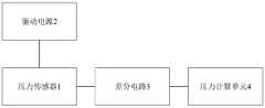
- Figure 1is a block diagram of a pressure detecting device according to a first embodiment of the present invention
- FIG. 2is a schematic structural view of a pressure sensor according to a first embodiment of the present invention
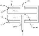
- FIG. 3is a first structural schematic view of a pressure sensor including a housing according to a first embodiment of the present invention
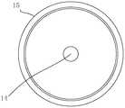
- Figure 4is a plan view of the pressure sensor of Figure 3;
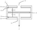
- Figure 5is a second schematic structural view of a pressure sensor including a housing in accordance with a first embodiment of the present invention
- Figure 6is a circuit schematic diagram of a pressure detecting device according to a second embodiment of the present invention.
- Figure 7is a circuit schematic diagram of a pressure detecting device according to a third embodiment of the present invention.
- Figure 8is a block diagram of a pressure detecting device in accordance with a fourth embodiment of the present invention.
- FIG. 9is a schematic structural diagram of a smart terminal according to a sixth embodiment of the present invention.
- FIG. 10is a schematic structural diagram of a smart terminal according to a seventh embodiment of the present invention.
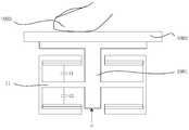
- FIG. 11is a side view of a smart terminal in accordance with an eighth embodiment of the present invention.
- Figure 12is a plan view of a smart terminal in accordance with an eighth embodiment of the present invention.
- a first embodiment of the present inventionrelates to a pressure detecting device.
- the pressure detecting device in this embodimentincludes a driving power source 2, a differential circuit 3, a pressure calculating unit 4, and at least one pressure sensor. 1.
- Each pressure sensor 1 in this embodimentincludes a first plate 11, a second plate 12, a third plate 13, a first elastic medium layer and a second elastic medium layer; the first plate 11 is located at the second pole Between the plate 12 and the third plate 13, the first elastic medium layer is disposed between the first plate 11 and the second plate 12, and the second elastic medium layer is disposed on the first plate 11 and the third plate 13.
- the first plate 11forms two detection capacitors C1 and C2 with the second plate 12 and the third plate 13 respectively.
- the pressure sensor 1outputs the detection voltages across the two detecting capacitors C1 and C2.
- an opening 14(as shown in FIG.
- the pressure sensor 1is connected between the driving power source 2 and the input end of the differential circuit 3; the output end of the differential circuit 3 is connected to the pressure calculating unit 4; wherein the first electrode plate 11 is subjected to a pressing force F applied from the outside, the pressure sensor 1
- the detection voltages across the two detection capacitors C1 and C2are output; the difference circuit 3 outputs the voltage difference between the two detection voltages; the pressure calculation unit 4 calculates the depression force F based on the voltage difference.
- the elastic medium layer in this embodimentmay be air.
- the pressure sensing device housingis grounded so that air can be used as the preferred dielectric layer.
- other elastic mediamay also be selected, but the embodiment does not specifically limit this.
- the pressure sensor 1may further include a housing 15 formed with a cavity.
- the structure of the pressure sensor 1 in this embodimentcan have two structural forms.
- FIG. 3shows the first configuration of the pressure sensor 1.
- the pressure sensor 1includes a housing 15 formed with a cavity, the housing 15 is made of a metal material, and the upper chamber wall and the lower chamber wall of the chamber are respectively provided with an insulating layer 16; a cantilever is formed in the middle of the housing 15, and both ends of the cantilever They are respectively fixed to the left and right chamber walls of the cavity, which is equivalent to the first plate 11 in FIG. Wherein, the upper chamber wall and the lower chamber wall respectively have an opening 14 communicating with the upper portion.
- the structure of the pressure sensor 1is not limited to the structure provided in the embodiment, and may be other shapes such as a cylinder, a square, an ellipse, a diamond, and the like.
- FIG. 5shows a second structural form of the pressure sensor 1.
- the pressure sensor 1includes a housing 15 formed with a cavity.
- the housing 15is made of a non-metallic material, and a metal layer is disposed in the suspension beam in the middle of the housing 15, that is, It is understood that the metal layer is fixed to the left cavity wall and the right cavity wall of the cavity by the suspension beam, and the metal layer is equivalent to the first electrode plate 11 in FIG. 2; the upper cavity wall and the lower cavity wall of the cavity are respectively provided with a conductive layer, Corresponding to the second plate 12 and the third plate 13 in FIG. 2, respectively.
- the second plate 12 and the third plate 13are respectively disposed on the upper cavity wall and the lower cavity wall of the cavity through an insulating layer 16.
- the upper chamber wall and the lower chamber wallrespectively have an opening 14 communicating with the upper portion.
- the insulating layer 16 and the conductive layermay be realized by a flexible circuit board.
- the substrate of the flexible circuit boardis directly fixed on the cavity wall to form the insulating layer 16; the exposed copper region of the flexible circuit board forms a conductive layer, that is, the exposed copper regions respectively form the second plate 12 and the third plate 13 .
- the specific implementation forms of the insulating layer 16, the second plate 12, and the third plate 13are not limited, and the materials and shapes of the second plate 12 and the third plate 13 may or may not be the same. the same.
- the distance between the first plate 11 and the second plate 12is d1, and the distance between the first plate 11 and the third plate 13 is d2.
- the structures, sizes, and materials of the first plate 11, the second plate 12, and the third plate 13are the same; and d1 and d2 are also the same; however, the embodiment does not impose any limitation.
- the external pressing memberapplies an upward pressing force F to the first plate 11 through the opening 14, and the first plate 11 generates an upward displacement with a displacement amount of ⁇ d.
- the direction of the pressing force F applied to the first plate 11can also be judged by the positive and negative of the difference between the two detecting capacitances.
- the second electrode plate 12has an opening 14 thereon, when the external pressing member applies a pressing force opposite to the pressing force F to the first electrode plate 11 through the opening 14, the first electrode plate 11 generates a certain deformation or displacement downward. The displacement is ⁇ d.
- the distance between the first plate 11 and the second plate 12is increased from d1 before pressing to (d1+ ⁇ d) after pressing, and d2 is reduced to (d2- ⁇ d), corresponding to C1 becomes (C1 - ⁇ C1), and C2 becomes (C2 + ⁇ C2).
- the pressure sensor provided in this embodimenthas a good suppression effect on changes in environmental conditions, such as temperature changes.
- ⁇ C1⁇ C2
- the change of temperaturedoes not affect the difference between the detection capacitor C1 and the detection capacitor C2. That is, when the temperature is different, the capacitance difference of the output of the pressure sensor 1 does not change, thereby greatly improving the anti-interference ability of the measurement circuit and improving the measurement of the circuit. Precision.
- the difference ⁇ C between the detection capacitor C1 and the detection capacitor C2 in the pressure sensor 1 provided in this embodimentis directly and linearly related to the pressing force F applied to the first plate 11, since the detection capacitor C1 corresponds to the detection capacitor C2.
- the voltage difference ⁇ V of the two detected voltagesis positively correlated with the capacitance difference ⁇ C, and therefore, the voltage difference ⁇ V is also linearly related to the pressing force F.
- the structural design of the pressure sensor in this embodimentmakes the detection voltage outputted by the pressure sensor linearly related to the pressing force, can suppress the influence of environmental condition changes on the circuit detection, has better stability, and can be widely applied to high temperature, low temperature, strong radiation, etc. In a hostile environment.
- the present embodimentadopts a differential circuit to effectively suppress the influence of environmental condition changes on circuit detection. Since the two inputs of the differential circuit are the inputs of two electrical signals, the difference between the two signals is the effective input signal of the circuit. If there is an interference signal, the same interference will be generated for the two input electrical signals. Calculate the difference between the two, so that the common mode interference of the two detection capacitors is cancelled, and the internal common mode noise is reduced, so that the effective input of the interference signal is zero.
- the differential circuit in this embodimentmay be implemented by a fully differential amplifier, or may be implemented by two single-ended amplifiers, and details are not described herein.
- FIG. 6is a circuit schematic diagram of the pressure detecting device using self-capacity detecting in the embodiment.
- the pressure detecting devicefurther includes: a charging switch 100B and a charging switch 200B, a discharging switch 100D, and a discharging switch 200D.
- the number of charging switchesis set to two, and the number of discharging switches is set to two.
- 6is equivalent to the detection capacitor C1 in FIG. 2, and C2 in FIG. 6 is equivalent to the detection capacitor C2 in FIG. 2; one end of C1 and C2 in FIG. 6 is equivalent to the first plate in FIG. 2; In FIG. 6, one end of C1 connected to the driving power source 2 through the charging switch 100B is equivalent to the second plate in FIG. 1, and one end of C2 connected to the driving power source 2 through the charging switch 200B is equivalent to the third plate in FIG.
- the charging switch 100B and the charging switch 200Bare used to charge C1 and C2 during pressure detection; wherein, C1 is connected to the forward input terminal Vin+ of the differential circuit 3 through the discharge switch 100D, and the reverse input of the C2 and the differential circuit 3
- the terminal Vin-is connected through the discharge switch 200D, and the discharge switch 100D and the discharge switch 200D are used to discharge the C1 and C2 at the time of pressure detection; the output of the differential circuit 3 is connected to the pressure calculation unit 4.
- the charging switch 100B and the charging switch 200Bare closed and the discharging switch 100D and the discharging switch 200D are turned off to charge C1 and C2; the charging switch 100B and the charging switch 200B are disconnected, and the discharging switch 100D and the discharging switch 200D are closed, C1 and C2. Enter the discharge state.
- the number of charging switches or discharging switchesis not limited to the description in the present embodiment.
- the number of charging switchescan also be set to one, and one charging switch is a double-pole double-throw switch; and/or the number of discharging switches can also be set to one, and one discharging switch is a double-pole double-throw switch, both of which can be realized with
- the technical effects of the technical solutions described in the embodimentsare the same; it should be noted that the number of charging switches and the number of discharging switches may be equal or not equal.
- the pressure detecting devicefurther includes a tunable capacitor 100C and a tunable capacitor 200C.
- the C1is electrically connected to the tunable capacitor 100C
- the C2is electrically connected to the tunable capacitor 200C. Adjusting the capacitance of the capacitor 100C and the adjustable capacitor 200C can adjust the matching relationship between the capacitance values of C1 and C2 during pressure detection.
- the pressure sensorsince the pressure sensor has a certain error in assembly, that is, when no pressing force is applied, there is a difference between the detecting capacitor C1 and the detecting capacitor C2.
- the difference in capacitance due to assembly errorsis transmitted to the differential circuit, causing erroneous electrical signal transmission.
- the matching relationship between the adjustable capacitor 100C and the adjustable capacitor 200Cfor example, separately adjusting the adjustable capacitor 100C, and/or simultaneously adjusting the second adjustable capacitor 200C, so that when no pressing force is applied, the difference The output of the circuit is zero.
- the adjustable capacitor 100C and the adjustable capacitor 200Care not necessarily configured at the same time, and may be configured alternatively.
- the capacitance value of the detecting capacitor C1can be smaller than the capacitance value of the detecting capacitor C2 at the time of design.
- the pressure detecting deviceincludes the adjustable capacitor 100C, and the 100C is connected in parallel with the detecting capacitor C1, and when no pressing force is applied, the pass can be Adjust the capacitance of the capacitor 100C to ensure that the output of the differential circuit is zero.
- the pressure sensor included in the pressure detecting device in this embodimentis a structure for self-capacity detection, and the structural form in the practical application can refer to FIG. 3.
- the outer casing 15 in FIG. 3is connected to the grounding layer (because of the cantilever beam of the outer casing)
- the driving power source 2corresponding to the second plate 12 and the third plate 13 being connected to the driving power source 2
- FIG. 7is a circuit schematic diagram of a pressure detecting device using mutual capacitance detecting in the embodiment.
- the first plate of the pressure sensor(please refer to FIG. 5) is connected to the driving power source 2; the second plate of the pressure sensor (refer to FIG. 5) is connected to the positive input terminal Vin+ of the differential circuit 3,
- the third plate 13(please refer to FIG. 5) is connected to the inverting input terminal Vin- of the differential circuit 3; the output of the differential circuit 3 is connected to the pressure calculating unit 4.
- the pressure detecting devicefurther includes a tunable capacitor 100C and a tunable capacitor 200C.
- a tunable capacitor 100Cand a tunable capacitor 200C.
- the pressure sensor included in the pressure detecting device in this embodimentis a structure for mutual capacitance detection, and the structural form in practical application can refer to FIG. 5, that is, the metal layer corresponding to the pressure sensor in FIG. 5 (ie, the first pole)
- the board 11)is connected to the driving power source 2.
- the first plate of the pressure sensoris connected to the driving power source 2, so that parasitic load capacitance is not generated, so the pressure detecting device of the embodiment has a higher capacitance change rate and higher detection accuracy.
- a fourth embodiment of the present inventionrelates to a pressure detecting device, and a block diagram is shown in FIG.
- This embodimentis an improvement of the first embodiment, and the main improvement is that the number of pressure sensors in the pressure detecting device is plural, and the pressure detecting device further includes a switching unit 5 for switching a plurality of pressure sensors Ground is connected to the differential circuit 3.
- each pressure sensoroutputs two detection voltages respectively;
- the switching unit 5transmits the two detection voltages of the first pressure sensor to the differential circuit 3;
- the switching unit 5transmits the two detection voltages of the second pressure sensor to the differential circuit 3; and so on,
- the switching unit 5switchesably connects the two detection voltages of the plurality of pressure sensor outputs to the differential circuit 3, facilitating the pressure calculation unit 4 to calculate the pressing force.
- a fifth embodiment of the present inventionrelates to an intelligent terminal, which may be, for example, an active pen, a smart phone, or the like.
- the smart terminal in this embodimentincludes the pressure detecting devices in any of the first to fourth embodiments.
- the smart terminal provided by the embodimentcan implement multi-dimensional input and expand the application scenario of the pressure detecting device.
- the sixth embodiment of the present inventionrelates to an intelligent terminal.
- the present embodimentis an improvement of the fifth embodiment.
- the main improvementis that the smart terminal of the embodiment is an active pen, and the active pen includes any one of the first to the fourth.
- a schematic structural view of the active penis as shown in FIG. 9.
- the active penfurther includes a pen case 901, a refill 902, and an insulating cap 903.
- the pressure detecting deviceis mounted in the pen case; one end of the refill 902 is fixed to the first plate 11 of the pressure sensor; the insulating pen cap 903 is sleeved on the other end of the refill 902 and has a predetermined distance 904 from the housing; The preset distance 904 is greater than or equal to the maximum deformation distance of the first plate 11; wherein the insulating cap 903 is applied to the first plate 11 of the pressure sensor through the refill 902 after being subjected to a pressing force applied from the outside.
- the pressure sensorincludes a casing, and the casing of the pressure sensor is directly fixed in the pen case 901; in practical applications, the casing of the pressure sensor may also be integrally formed with the pen case 901.
- One end of the refill 902passes through the opening on the third plate and is fixed to the first plate 11 of the pressure sensor; the insulating cap 903 is sleeved on the other end of the refill 902 and has a predetermined distance 904 from the pen case 901, wherein The preset distance 904 is greater than or equal to the maximum deformation distance when the first plate 11 is deformed.
- one end of the refill 902can also be fixed to the side wall of the first electrode plate 11 of the pressure sensor, that is, the third electrode plate does not need to form an opening, and the end of the refill 902 can also be realized by the pressure sensor.
- the first plate 11applies a pressing force.
- the pen core 902acts on the first plate 11 of the pressure sensor, and the maximum stroke range of the pen tip is the preset distance 904.
- the design of the active pen tip structure using the pressure detecting device in the embodimentis very simple. Since the pressure sensor structure is added to the conventional active pen, the active pen can sense the pressure and the stroke of the writing head is small. Therefore, the writing experience is close to the real pen, and a good user experience can be obtained.
- the seventh embodiment of the present inventionrelates to a smart terminal.
- the present embodimentis an improvement of the fifth embodiment.
- the main improvementis that the smart terminal of the embodiment is a device including fingerprint recognition, and the device including fingerprint recognition includes The pressure detecting device in any of the first to fourth embodiments.
- the device including fingerprint recognitionfurther includes a fingerprint recognition module 1002 for identifying a fingerprint of a user and a pressing member 1001; one end of the pressing member 1001 is connected to the fingerprint recognition module 1002, and the other end is connected to the pressure sensor.
- the pressure sensoris located under the fingerprint recognition module 1002, and the finger 1003 presses the fingerprint recognition module 1002, and the pressure F is transmitted to the pressure sensor through the pressing member 1001.
- the pressure F of the fingercan be detected.
- the pressure detecting device in this embodimentcan also be made into a simple pressure button on the mobile terminal, thereby adding a linear input dimension.
- the pressing member in the embodimentneeds to trigger the displacement of the first plate under the external force, and the pressing member may be directly integrated/located on the fingerprint recognition module or independent of the fingerprint recognition module.
- the surface of the fingerprint recognition modulecan be directly pressed, and the first plate is displaced by the mechanical structure.
- the strength perception of the smart terminalcan be realized, and whether the click action or the press action is recognized, whether it is a light press or a heavy press action, thereby calling up a corresponding function, and increasing a linear input dimension of the smart terminal.
- the eighth embodiment of the present inventionrelates to an intelligent terminal.
- the present embodimentis an improvement of the fifth embodiment.
- the main improvementis that the smart terminal in this embodiment is a mobile terminal, and the mobile terminal includes first to fourth.
- FIG. 11is a schematic diagram of a mobile terminal.
- the mobile terminalfurther includes a terminal housing 1103, a display module 1104, and a plurality of pressing members.
- the pressure detecting deviceis disposed in the terminal housing 1103, and the number of pressure sensors and the number of pressing members are One end of the plurality of pressing members is respectively fixed to the display module 1104, and the other end is respectively fixed to the first plate 11 of the plurality of pressure sensors; wherein, after the display module 1104 is subjected to the pressing force F applied from the outside, The pressing member acts on the first plate 11 of the plurality of pressure sensors.
- the number of the pressing membersis set to four.
- the four pressing membersare 1101, 1102, 1106, and 1107, respectively.
- the display module 1104can move up and down with respect to the mobile terminal housing 1103; the pressure F is transmitted to the display module 1104 to
- the pressure sensors 1101, 1102, 1106, and 1107deform the first plate in the pressure sensor, and the four pressure sensors output the detection voltage, which can be detected according to the principles of the first to fourth embodiments of the present invention. Press the pressure F size.
- this pressure detecting devicecan be used not only To sense the pressure of the finger touch, if combined with the special software with metering function, the traditional mobile terminal can have the function of high-precision electronic scale, and realize the purpose of integrating various application functions of the mobile terminal, which greatly expands.
- the application scenario of the mobile terminalhelps to enhance the user experience.
- the pressing member in the embodimentneeds to be triggered to generate displacement by the external force under the external force, and the pressing member may be directly integrated/located on the display module or independent of the display module.
- the surface of the display module of the mobile terminalcan be directly pressed, and the displacement of the first plate is driven by the mechanical structure.
- each module involved in this embodimentis a logic module.
- a logical unitmay be a physical unit, a part of a physical unit, or multiple physical entities. A combination of units is implemented.
- the present embodimentdoes not introduce a unit that is not closely related to solving the technical problem proposed by the present invention, but this does not mean that there are no other units in the present embodiment.
- a program instructing related hardwaremay be completed by a program instructing related hardware, and the program is stored in a storage medium, and includes a plurality of instructions for making a device (which may be a single chip microcomputer). , a chip, etc. or a processor performs all or part of the steps of the methods described in various embodiments of the present application.
- the foregoing storage mediumincludes: a U disk, a mobile hard disk, a read-only memory (ROM), a random access memory (RAM), a magnetic disk, or an optical disk, and the like. .
Landscapes
- Engineering & Computer Science (AREA)
- Theoretical Computer Science (AREA)
- General Engineering & Computer Science (AREA)
- Physics & Mathematics (AREA)
- General Physics & Mathematics (AREA)
- Human Computer Interaction (AREA)
- Power Engineering (AREA)
- Computing Systems (AREA)
- Quality & Reliability (AREA)
- Multimedia (AREA)
- Mathematical Physics (AREA)
- Force Measurement Appropriate To Specific Purposes (AREA)
- Measuring Fluid Pressure (AREA)
Abstract
Description
Translated fromChinese本发明涉及输入设备技术领域,特别涉及一种压力检测装置及智能终端。The present invention relates to the field of input device technologies, and in particular, to a pressure detecting device and an intelligent terminal.
电容式触控技术通过检测电容能够感知用户手指或者其他导电物体是否存在,只需手指轻触即可实现相应功能。目前,触控屏已经广泛应用于电子设备,以实现触控操作。Capacitive touch technology can detect the presence of a user's finger or other conductive objects by detecting the capacitance, and the corresponding function can be realized by simply touching the finger. Currently, touch screens have been widely used in electronic devices to implement touch operations.
在实现本发明过程中,发明人发现现有技术中至少存在如下问题:In the process of implementing the present invention, the inventors have found that at least the following problems exist in the prior art:
(1)现有电子设备的输入维度单一,不能同时进行多维度的输入,压力检测不够准确,(1) The input dimension of the existing electronic equipment is single, and multi-dimensional input cannot be performed at the same time, and the pressure detection is not accurate enough.
(2)单纯的手指触控功能应用场景单一,与电子设备集成多种应用功能的技术发展趋势不符。(2) The simple finger touch function application scenario is single, and the technical development trend of integrating multiple application functions with electronic devices does not match.
发明内容Summary of the invention
本发明实施方式的目的在于提供一种压力检测装置及智能终端,提高了压力检测的检测精度;同时,该压力检测装置应用于智能终端时能够实现智能终端的多功能化。An object of the present invention is to provide a pressure detecting device and an intelligent terminal, which improve the detection accuracy of the pressure detection. Meanwhile, when the pressure detecting device is applied to the intelligent terminal, the multifunctional terminal of the smart terminal can be realized.
为解决上述技术问题,本发明的实施方式提供了一种压力检测装置,包括:驱动电源、差分电路、压力计算单元以及至少一个压力传感器;每个压力传感器包括第一极板、第二极板、第三极板、第一弹性介质层以及第二弹性介质层;第一极板位于第二极板及第三极板之间,第一弹性介质层设置于第一极板与第二极板之间,第二弹性介质层设置于第一极板与第三极板之间;其中,第一极板分别与第二极板、第三极板形成两个检测电容;压力传感器连接于驱动电源与差分电路的输入端之间;差分电路的输出端连接于压力计算单元;其中,第一极板受到外界施加的按压力时,压力传感器输出两个检测电容两端的检测电压;差分电路输出两个检测电压的电压差值;压力计算单元根据电压差值计算按压力。In order to solve the above technical problem, an embodiment of the present invention provides a pressure detecting device including: a driving power source, a differential circuit, a pressure calculating unit, and at least one pressure sensor; each pressure sensor includes a first plate and a second plate a third plate, a first elastic medium layer and a second elastic medium layer; the first plate is located between the second plate and the third plate, and the first elastic medium layer is disposed onBetween the first plate and the second plate, the second elastic medium layer is disposed between the first plate and the third plate; wherein the first plate forms two with the second plate and the third plate respectively a detecting capacitor; the pressure sensor is connected between the driving power source and the input end of the differential circuit; the output end of the differential circuit is connected to the pressure calculating unit; wherein, when the first plate is subjected to a pressing force applied by the outside, the pressure sensor outputs two detecting The detection voltage across the capacitor; the differential circuit outputs the voltage difference between the two detected voltages; the pressure calculation unit calculates the pressing force based on the voltage difference.
本发明的实施方式还提供了一种智能终端,包括第一实施方式中的压力检测装置。An embodiment of the present invention also provides an intelligent terminal including the pressure detecting device in the first embodiment.
本发明实施方式相对于现有技术而言,第一极板受到外界施加的按压力时产生位移或形变,此时,第一极板与第二极板、第一极板与第三极板之间形成的两个检测电容发生变化,压力传感器对应输出两个检测电压;差分电路据此输出电压差值,再由压力计算单元计算出按压力;从而提高了压力检测的检测精度;同时,该压力检测装置应用于智能终端时能够实现智能终端的多功能化。Compared with the prior art, the first plate is displaced or deformed by the pressing force applied by the outside. At this time, the first plate and the second plate, the first plate and the third plate The two detection capacitors formed between the two change voltages are respectively outputted by the pressure sensor; the differential circuit outputs the voltage difference according to the difference, and the pressure calculation unit calculates the pressing force; thereby improving the detection accuracy of the pressure detection; When the pressure detecting device is applied to an intelligent terminal, the multifunctional function of the smart terminal can be realized.
另外,第一极板连接于驱动电源,第二极板与第三极板分别连接于差分电路的输入端。In addition, the first plate is connected to the driving power source, and the second plate and the third plate are respectively connected to the input end of the differential circuit.
另外,压力检测装置还包括:至少一充电开关与至少一放电开关;第一极板接地;第二极板与第三极板分别通过充电开关连接至驱动电源,且分别通过放电开关连接至差分电路的输入端。In addition, the pressure detecting device further includes: at least one charging switch and at least one discharging switch; the first plate is grounded; the second plate and the third plate are respectively connected to the driving power source through the charging switch, and are respectively connected to the difference through the discharging switch The input of the circuit.
另外,充电开关的数目为二个,第二极板与第三极板分别通过二个充电开关连接于驱动电源;和/或放电开关的数目为二个,第二极板与所述第三极板分别通过二个放电开关连接于差分电路的输入端;其中,充电开关闭合时,两个检测电容进行充电;放电开关闭合时,所述两个检测电容进行放电。In addition, the number of the charging switches is two, and the second plate and the third plate are respectively connected to the driving power source through two charging switches; and/or the number of the discharging switches is two, the second plate and the third plate The plates are respectively connected to the input end of the differential circuit through two discharge switches; wherein, when the charging switch is closed, the two detecting capacitors are charged; when the discharging switch is closed, the two detecting capacitors are discharged.
另外,充电开关的数目为一个且充电开关为双刀双掷开关;和/或放电开关的数目为一个且放电开关为双刀双掷开关;其中,充电开关闭合时,两个检测电容进行充电;放电开关闭合时,两个检测电容进行放电。In addition, the number of charging switches is one and the charging switch is a double-pole double-throw switch; and/or the number of discharging switches is one and the discharging switch is a double-pole double-throw switch; wherein, when the charging switch is closed, twoThe detection capacitor is charged; when the discharge switch is closed, the two detection capacitors are discharged.
另外,压力检测装置还包含两个可调电容;两个可调电容分别与两个检测电容并联连接;其中,两个可调电容用于调节两个检测电容所在通路的电容值,以使得在第一极板未受到外界施加的按压力时,两个检测电容所在通路的初始电容相等。在本实施例中,通过调节两个可调电容可以克服制造装配过程中的公差导致的检测误差。In addition, the pressure detecting device further comprises two adjustable capacitors; two adjustable capacitors are respectively connected in parallel with the two detecting capacitors; wherein the two adjustable capacitors are used for adjusting the capacitance values of the paths of the two detecting capacitors, so that When the first plate is not subjected to the pressing force applied from the outside, the initial capacitance of the path where the two detecting capacitors are located is equal. In the present embodiment, the detection error caused by the tolerance in the manufacturing assembly process can be overcome by adjusting the two adjustable capacitances.
另外,在第一极板未受到外界施加的按压力时,两个检测电容所在通路的初始电容不相等;压力检测装置还包括一个可调电容,可调电容与初始电容较小的通路上的检测电容并联连接;其中,可调电容用于调节与可调电容并联连接的检测电容所在通路的电容值,以使得在第一极板未受到外界施加的按压力时,两个检测电容所在通路的初始电容相等。本实施例提供了克服制造装配过程中的公差导致的检测误差的另一种实现方式。In addition, when the first plate is not subjected to the externally applied pressing force, the initial capacitances of the paths of the two detecting capacitors are not equal; the pressure detecting device further includes a tunable capacitor, and the adjustable capacitor is on the path with a smaller initial capacitance. The detecting capacitors are connected in parallel; wherein the adjustable capacitor is used for adjusting the capacitance value of the path of the detecting capacitor connected in parallel with the adjustable capacitor, so that when the first plate is not subjected to the externally applied pressing force, the paths of the two detecting capacitors are The initial capacitance is equal. This embodiment provides another implementation that overcomes the detection error caused by tolerances in the manufacturing assembly process.
另外,压力传感器的数目为多个;压力检测装置还包括切换单元;多个压力传感器通过切换单元可切换地连接至差分电路。本实施例通过切换单元可以将多个压力传感器输出的多个检测电压可切换地连接到差分电路,从而简化电路结构。In addition, the number of pressure sensors is plural; the pressure detecting device further includes a switching unit; and the plurality of pressure sensors are switchably connected to the differential circuit through the switching unit. In the present embodiment, a plurality of detection voltages output from a plurality of pressure sensors can be switchably connected to the differential circuit by the switching unit, thereby simplifying the circuit configuration.
另外,智能终端为主动笔;主动笔还包括笔壳、笔芯以及绝缘笔帽;压力检测装置安装在笔壳中;笔芯的一端固定于压力传感器的第一极板;绝缘笔帽套设于笔芯的另一端且与壳体具有预设距离;预设距离大于或等于第一极板的最大形变距离;其中,绝缘笔帽受到外界施加的按压力后,通过笔芯作用于压力传感器的第一极板。本实施例将传统的主动笔与压力检测装置相结合,使传统的主动笔能够模拟真笔书写,灵敏度和精确率更高。In addition, the smart terminal is an active pen; the active pen further includes a pen case, a refill and an insulating pen cap; the pressure detecting device is installed in the pen case; one end of the refill is fixed to the first plate of the pressure sensor; and the insulating pen cap is sleeved on the pen The other end of the core has a predetermined distance from the housing; the preset distance is greater than or equal to the maximum deformation distance of the first plate; wherein, after the insulating cap is subjected to the pressing force applied by the outside, the first force acting on the pressure sensor through the pen core Plate. This embodiment combines the conventional active pen with the pressure detecting device, so that the conventional active pen can simulate real pen writing with higher sensitivity and accuracy.
另外,智能终端为包括指纹识别的装置;包括指纹识别的装置还包括用于识别用户指纹的指纹识别模组与按压件;按压件的一端连接于指纹识别模组,另一端连接于压力传感器的第一极板;其中,指纹识别模组受到外界施加的按压力后,通过按压件作用于压力传感器的第一极板。本实施例将传统的指纹识别模组与压力检测装置相结合,使传统的指纹识别模组能够感知按压力大小,从而实现了指纹识别模组的多维度输入。In addition, the smart terminal is a device including fingerprint recognition; the device including fingerprint recognition further includes a fingerprint recognition module and a pressing member for recognizing a fingerprint of the user; one end of the pressing member is connected to the fingerprint recognition module, and the other end is connected to the pressure sensor. a first plate; wherein the fingerprint recognition module is subjected to external applicationAfter the applied pressing force, the first plate of the pressure sensor is applied by the pressing member. In this embodiment, the traditional fingerprint recognition module is combined with the pressure detecting device, so that the traditional fingerprint recognition module can sense the pressing force, thereby realizing the multi-dimensional input of the fingerprint recognition module.
另外,智能终端为移动终端;移动终端还包括终端壳体、显示模组以及多个按压件;压力检测装置设置于终端壳体内,且压力传感器的数目与按压件的数目相同;多个按压件的一端分别固定于显示模组,另一端分别固定于多个压力传感器的第一极板;其中,显示模组受到外界施加的按压力后,通过多个按压件作用于多个压力传感器的第一极板。本实施例将传统的移动终端与压力检测装置相结合,使传统的智能终端具有高精度电子秤的功能,集成了更多的功能应用,扩展了智能终端的应用场景,有助于提升用户体验。In addition, the smart terminal is a mobile terminal; the mobile terminal further includes a terminal housing, a display module, and a plurality of pressing members; the pressure detecting device is disposed in the terminal housing, and the number of the pressure sensors is the same as the number of the pressing members; the plurality of pressing members One end is respectively fixed to the display module, and the other end is respectively fixed to the first plate of the plurality of pressure sensors; wherein, after the display module is subjected to the pressing force applied by the outside, the plurality of pressing members act on the plurality of pressure sensors A plate. In this embodiment, the traditional mobile terminal is combined with the pressure detecting device, so that the traditional intelligent terminal has the function of the high-precision electronic scale, integrates more functional applications, and expands the application scenario of the intelligent terminal, which helps to enhance the user experience. .
图1是根据本发明第一实施例的压力检测装置的方框图;Figure 1 is a block diagram of a pressure detecting device according to a first embodiment of the present invention;
图2是根据本发明第一实施例中的压力传感器的结构示意图;2 is a schematic structural view of a pressure sensor according to a first embodiment of the present invention;
图3是根据本发明第一实施例的包括外壳的压力传感器的第一种结构示意图;3 is a first structural schematic view of a pressure sensor including a housing according to a first embodiment of the present invention;
图4是图3中的压力传感器的俯视图;Figure 4 is a plan view of the pressure sensor of Figure 3;
图5是根据本发明第一实施例中的包括外壳的压力传感器的第二种结构示意图;Figure 5 is a second schematic structural view of a pressure sensor including a housing in accordance with a first embodiment of the present invention;
图6是根据本发明第二实施例的压力检测装置的电路原理图;Figure 6 is a circuit schematic diagram of a pressure detecting device according to a second embodiment of the present invention;
图7是根据本发明第三实施例的压力检测装置的电路原理图;Figure 7 is a circuit schematic diagram of a pressure detecting device according to a third embodiment of the present invention;
图8是根据本发明第四实施例的压力检测装置的方框图;Figure 8 is a block diagram of a pressure detecting device in accordance with a fourth embodiment of the present invention;
图9是根据本发明第六实施例的智能终端的结构示意图;FIG. 9 is a schematic structural diagram of a smart terminal according to a sixth embodiment of the present invention; FIG.
图10是根据本发明第七实施例的智能终端的结构示意图;FIG. 10 is a schematic structural diagram of a smart terminal according to a seventh embodiment of the present invention; FIG.
图11是根据本发明第八实施例的智能终端的侧视图;Figure 11 is a side view of a smart terminal in accordance with an eighth embodiment of the present invention;
图12是根据本发明第八实施例的智能终端的俯视图。Figure 12 is a plan view of a smart terminal in accordance with an eighth embodiment of the present invention.
为使本发明的目的、技术方案和优点更加清楚,下面将结合附图对本发明的各实施方式进行详细的阐述。然而,本领域的普通技术人员可以理解,在本发明各实施方式中,为了使读者更好地理解本申请而提出了许多技术细节。但是,即使没有这些技术细节和基于以下各实施方式的种种变化和修改,也可以实现本申请所要求保护的技术方案。In order to make the objects, technical solutions, and advantages of the present invention more apparent, the embodiments of the present invention will be described in detail below. However, it will be apparent to those skilled in the art that, in the various embodiments of the present invention, numerous technical details are set forth in order to provide the reader with a better understanding of the present application. However, the technical solutions claimed in the present application can be implemented without these technical details and various changes and modifications based on the following embodiments.
本发明的第一实施例涉及一种压力检测装置,如图1、图2所示,本实施例中的压力检测装置包括:驱动电源2、差分电路3、压力计算单元4以及至少一个压力传感器1。A first embodiment of the present invention relates to a pressure detecting device. As shown in FIGS. 1 and 2, the pressure detecting device in this embodiment includes a
本实施例中的每个压力传感器1包括第一极板11、第二极板12、第三极板13、第一弹性介质层以及第二弹性介质层;第一极板11位于第二极板12及第三极板13之间,第一弹性介质层设置于第一极板11与第二极板12之间,第二弹性介质层设置于第一极板11与第三极板13之间;其中,第一极板11分别与第二极板12、第三极板13形成两个检测电容C1与C2。第一极板11受到外界施加的按压力F时,压力传感器1输出两个检测电容C1与C2两端的检测电压。其中,第二极板12、第三极板13的中间可以分别开设一开口14(如图2中所示),以供外界对第一极板11施加按压力;然不限于此,可以选择在第二极板12、第三极板13中的一个上开设开口,或者,第二极板12、第三极板13无需开设开口,外界可以通过第一极板的侧边对第一极板施加按压力。Each
压力传感器1连接于驱动电源2与差分电路3的输入端之间;差分电路3的输出端连接于压力计算单元4;其中,第一极板11受到外界施加的按压力F时,压力传感器1输出两个检测电容C1与C2两端的检测电压;差分电路3输出两个检测电压的电压差值;压力计算单元4根据电压差值计算按压力F。The
较佳的,本实施例中弹性介质层可以是空气。于实际应用时,压力检测装置外壳接地,因此可以将空气作为优选的介质层。当然,还可以选择其他弹性介质,然本实施方式对此不作具体限制。Preferably, the elastic medium layer in this embodiment may be air. In practical applications, the pressure sensing device housing is grounded so that air can be used as the preferred dielectric layer. Of course, other elastic media may also be selected, but the embodiment does not specifically limit this.
实际上的,如图3、图4、图5所示,压力传感器1还可以包括形成有腔体的外壳15。本实施例中的压力传感器1的结构可以有两种结构形式。In fact, as shown in FIGS. 3, 4, and 5, the
图3所示为压力传感器1的第一种结构形式。压力传感器1包括形成有腔体的外壳15,外壳15由金属材料制成,腔体的上腔壁和下腔壁分别设有绝缘层16;外壳15的中间形成有悬臂,该悬臂的两端分别固定于腔体的左腔壁和右腔壁,该悬臂相当于图2中的第一极板11。其中,上腔壁和下腔壁上分别具有连通于上的开口14。Figure 3 shows the first configuration of the
图4为本实施例中图3中压力传感器结构的俯视图,包括外壳15和开口14。在其他实施例中,压力传感器1的结构并不限于本实施例中提供的结构,可以为一个圆筒状、方形、椭圆、菱形等其他形状。4 is a top plan view of the pressure sensor structure of FIG. 3 in the present embodiment, including a
图5所示为压力传感器1的第二种结构形式,压力传感器1包括形成有腔体的外壳15,外壳15由非金属材料制成,外壳15中间的悬梁内设置有金属层,即,可以理解为金属层通过悬梁固定于腔体的左腔壁和右腔壁,该金属层相当于图2中的第一极板11;腔体的上腔壁和下腔壁分别设有导电层,分别相当于图2中的第二极板12与第三极板13。较佳的,第二极板12与第三极板13可以分别通过一个绝缘层16设置于腔体的上腔壁和下腔壁。其中,上腔壁和下腔壁上分别具有连通于上的开口14。FIG. 5 shows a second structural form of the
本实施方式中,绝缘层16与导电层可以由柔性电路板实现。具体而言,柔性电路板的基板直接固定在腔壁上,形成绝缘层16;柔性电路板的露铜区形成导电层,即,露铜区分别形成第二极板12与第三极板13。然而,本实施方式对绝缘层16、第二极板12及第三极板13的具体实现形式不作任何限定,第二极板12与第三极板13的材质和形状可以相同,也可以不相同。In this embodiment, the insulating
如下是对本实施方式的压力传感器1的作动方式与原理的具体说明。The following is a detailed description of the operation mode and principle of the
第一极板11与第二极板12之间的距离为d1,第一极板11与第三极板13之间的距离为d2。本实施例中,第一极板11、第二极板12以及第三极板13的结构、尺寸和材质均相同;且d1、d2也相同;然本实施例对此不作任何限制。The distance between the
当未对第一极板11施加按压力时,第一极板11不会产生形变或位移,此时,d1=d2,C1=C2,压力传感器1输出的两个检测电压相等。When the pressing force is not applied to the
具体地,当第三极板13具有开口14时,外部按压件穿过开口14向第一极板11施加向上的按压力F,第一极板11产生向上的位移,位移量为Δd。此时,第一极板11与第二极板12之间的距离由按压前的d1变小成按压后的(d1-Δd),d2变大成(d2+Δd),对应的C1变为(C1+ΔC1),C2变为(C2-ΔC2),此时,两个检测电容C1与C2之间的变化量为ΔC=(C1+ΔC1)-(C2-ΔC2)=ΔC1+ΔC2。当Δd相对于d1、d2的值很小的的时候,有如下关系,其中k为常数,与三个极板的结构、尺寸和材质直接相关,F为向第一极板11施加的按压力。Specifically, when the
ΔC=kFΔC=kF
在本实施例中还可以通过两个检测电容之间差值的正负判断施加于第一极板11上按压力F的方向。当第二极板12上具有开口14时,外部按压件穿过开口14向第一极板11施加与按压力F相反的的按压力时,第一极板11向下产生一定的形变或位移,位移量为Δd。此时,第一极板11与第二极板12之间的距离由按压前的d1变大成按压后的(d1+Δd),d2变小成(d2-Δd),对应的C1变为(C1-ΔC1),C2变为(C2+ΔC2),此时,两个检测电容的变化量为ΔC=(C1-ΔC1)-(C2+ΔC2)=-(ΔC1+ΔC2)。当Δd相对于d1、d2的值很小的的时候,有如下关系,其中k为常数,与三个极板的结构、尺寸和材质直接相关,F为向第一极板11施加的按压力。In the present embodiment, the direction of the pressing force F applied to the
ΔC=-kFΔC=-kF
另外,本实施例提供的压力传感器对环境条件的变化,如温度变化等,具有很好的抑制效果。具体地,假设在温度为T1的时候,C1-C2=ΔC;温度变化为T2的时候,C1和C2都会发生变化,分别为C1+ΔC1和C2+ΔC2,再由于第一极板11和第二极板12、第三极板13的电极形状和面积完全一样,所以ΔC1=ΔC2,这样C1+ΔC1-(C2+ΔC2)=C1+-C2+(ΔC1-ΔC2)=ΔC,由此可知,环境温度的变化不会影响检测电容C1和检测电容C2的差值,即,温度不同时,压力传感器1输出的电容差值不变,从而大大提高了测量电路的抗干扰能力,提高了电路的测量精度。In addition, the pressure sensor provided in this embodiment has a good suppression effect on changes in environmental conditions, such as temperature changes. Specifically, suppose that when the temperature is T1, C1-C2=ΔC; when the temperature changes to T2, both C1 and C2 change, respectively C1+ΔC1 and C2+ΔC2, and then due to the
由上述分析可知,本实施例提供的压力传感器1中检测电容C1与检测电容C2的差值ΔC与施加于第一极板11的按压力F直接线性相关,由于检测电容C1与检测电容C2对应输出的两个检测电压的电压差值ΔV与电容差值ΔC成正相关,因此,电压差值ΔV与按压力F也呈线性相关。本实施例中压力传感器的结构设计使得压力传感器输出的检测电压与按压力线性相关,能够抑制环境条件变化对电路检测造成的影响,稳定性更好,可以广泛应用于高温、低温、强辐射等恶劣环境中。It can be seen from the above analysis that the difference ΔC between the detection capacitor C1 and the detection capacitor C2 in the
本实施方式与现有技术相比,采用了差分电路可以有效抑制环境条件变化给电路检测造成的影响。由于差分电路的两个输入端是两个电信号的输入,这两个信号的差值是电路的有效输入信号,如果存在干扰信号,会对两个输入的电信号均产生相同的干扰,通过计算二者的差值,这样就把对两个检测电容的共模干扰抵消掉,降低电路内部共模噪声,使干扰信号的有效输入为零。Compared with the prior art, the present embodiment adopts a differential circuit to effectively suppress the influence of environmental condition changes on circuit detection. Since the two inputs of the differential circuit are the inputs of two electrical signals, the difference between the two signals is the effective input signal of the circuit. If there is an interference signal, the same interference will be generated for the two input electrical signals. Calculate the difference between the two, so that the common mode interference of the two detection capacitors is cancelled, and the internal common mode noise is reduced, so that the effective input of the interference signal is zero.
当然,本实施方式中的差分电路既可以由全差分放大器实现,也可由两路单端放大器实现差分检测,详细不再赘述。Certainly, the differential circuit in this embodiment may be implemented by a fully differential amplifier, or may be implemented by two single-ended amplifiers, and details are not described herein.
本发明的第二实施例涉及一种压力检测装置,图6为本实施例中压力检测装置利用自容检测的电路原理图。本实施例中,压力检测装置还包含:充电开关100B和充电开关200B、放电开关100D和放电开关200D。A second embodiment of the present invention relates to a pressure detecting device, and FIG. 6 is a circuit schematic diagram of the pressure detecting device using self-capacity detecting in the embodiment. In this embodiment, the pressure detecting device further includes: a charging
在本实施例中,以充电开关数目设置为两个、放电开关数目设置为两个举例说明。图6中C1等效于图2中的检测电容C1,图6中C2等效于图2中检测电容C2;图6中C1和C2接地的一端等效于图2中的第一极板;图6中C1通过充电开关100B连接于驱动电源2的一端等效于图1中的第二极板,C2通过充电开关200B连接于驱动电源2的一端等效于图1中的第三极板,充电开关100B和充电开关200B用于在压力检测时对C1和C2进行充电处理;其中,C1与差分电路3的正向输入端Vin+通过放电开关100D连接,C2与差分电路3的反向输入端Vin-通过放电开关200D连接,放电开关100D和放电开关200D用于在压力检测时对C1和C2进行放电处理;差分电路3的输出端连接于压力计算单元4。In the present embodiment, the number of charging switches is set to two, and the number of discharging switches is set to two. 6 is equivalent to the detection capacitor C1 in FIG. 2, and C2 in FIG. 6 is equivalent to the detection capacitor C2 in FIG. 2; one end of C1 and C2 in FIG. 6 is equivalent to the first plate in FIG. 2; In FIG. 6, one end of C1 connected to the driving
具体地,充电开关100B、充电开关200B闭合且放电开关100D、放电开关200D断开,对C1、C2充电;充电开关100B、充电开关200B断开且放电开关100D、放电开关200D闭合,C1、C2进入放电状态。Specifically, the charging
当然,在其他实施例中,充电开关或放电开关的数目并不限于本实施方式中的描述。充电开关的数目也可设置为一个,且一个充电开关为双刀双掷开关;和/或放电开关的数目也可设置为一个,且一个放电开关为双刀双掷开关,均能实现与本实施例中描述的技术方案相同的技术效果;需要说明的是,充电开关的数目与放电开关的数目可以相等,也可以不相等。Of course, in other embodiments, the number of charging switches or discharging switches is not limited to the description in the present embodiment. The number of charging switches can also be set to one, and one charging switch is a double-pole double-throw switch; and/or the number of discharging switches can also be set to one, and one discharging switch is a double-pole double-throw switch, both of which can be realized with The technical effects of the technical solutions described in the embodiments are the same; it should be noted that the number of charging switches and the number of discharging switches may be equal or not equal.
本实施例中,较佳的,压力检测装置还包括可调电容100C、可调电容200C,C1电连接于可调电容100C,C2电连接于可调电容200C,根据对可调电容100C、可调电容200C的调节,可以调整C1与C2在压力检测时电容值的大小匹配关系。In this embodiment, the pressure detecting device further includes a
具体而言,由于压力传感器在装配时存在一定的误差,即在没有施加按压力时,检测电容C1与检测电容C2之间存在差值。由于装配误差导致的电容差值就会传输给差分电路,从而引起错误的电信号传输。此时,通过调整可调电容100C和可调电容200C之间的匹配关系,比如,单独调节可调电容100C,和/或,同时调节第二可调电容200C,使得没有施加按压力时,差分电路的输出为0。Specifically, since the pressure sensor has a certain error in assembly, that is, when no pressing force is applied, there is a difference between the detecting capacitor C1 and the detecting capacitor C2. The difference in capacitance due to assembly errors is transmitted to the differential circuit, causing erroneous electrical signal transmission. At this time, by adjusting the matching relationship between the
需要说明的是,在其他实施例中,并不必须同时配置有可调电容100C、可调电容200C,也可以择一进行配置。比如,可以在设计时将检测电容C1的电容值小于检测电容C2的电容值,此时,压力检测装置包含可调电容100C,100C与检测电容C1并联连接,在没有施加按压力时,通过可调电容100C的调整,保证差分电路的输出为0。It should be noted that, in other embodiments, the
本实施例中压力检测装置包含的压力传感器为用于自容检测的结构,其实际应用中的结构形式可参考图3,此时,图3中的外壳15连接于接地层(由于外壳的悬梁作为第一极板11,即相当于第一极板11接地),两个导电层分别连接于驱动电源2(相当于第二极板12与第三极板13连接于驱动电源2),因此使得电路结构更加比较简单。The pressure sensor included in the pressure detecting device in this embodiment is a structure for self-capacity detection, and the structural form in the practical application can refer to FIG. 3. At this time, the
本发明第三实施例涉及一种压力检测装置,图7为本实施例中压力检测装置利用互容检测的电路原理图。在本实施例中,压力传感器的第一极板(请参考图5)连接于驱动电源2;压力传感器的第二极板(请参考图5)连接于差分电路3的正向输入端Vin+,第三极板13(请参考图5)连接于差分电路3的反向输入端Vin-;差分电路3的输出端连接于压力计算单元4。A third embodiment of the present invention relates to a pressure detecting device, and FIG. 7 is a circuit schematic diagram of a pressure detecting device using mutual capacitance detecting in the embodiment. In this embodiment, the first plate of the pressure sensor (please refer to FIG. 5) is connected to the driving
本实施例中,较佳的,压力检测装置还包括可调电容100C、可调电容200C,详细分析请参见本发明第二实施例,在此不再赘述。In this embodiment, the pressure detecting device further includes a
本实施例中压力检测装置包含的压力传感器为用于互容检测的结构,其实际应用中的结构形式可参考图5,即,相当于图5中的压力传感器的金属层(即第一极板11)连接于驱动电源2。与自容检测原理相比,压力传感器的第一极板连接于驱动电源2,因此不会产生寄生负载电容,所以本实施例的压力检测装置具有更高的电容变化率,检测精度更高。The pressure sensor included in the pressure detecting device in this embodiment is a structure for mutual capacitance detection, and the structural form in practical application can refer to FIG. 5, that is, the metal layer corresponding to the pressure sensor in FIG. 5 (ie, the first pole) The board 11) is connected to the driving
本发明第四实施例涉及一种压力检测装置,方框示意图如图8所示。本实施例是对第一实施方式的改进,主要改进之处在于:压力检测装置中的压力传感器的数目为多个,压力检测装置还包括有切换单元5,用于将多个压力传感器可切换地连接于差分电路3。A fourth embodiment of the present invention relates to a pressure detecting device, and a block diagram is shown in FIG. This embodiment is an improvement of the first embodiment, and the main improvement is that the number of pressure sensors in the pressure detecting device is plural, and the pressure detecting device further includes a switching unit 5 for switching a plurality of pressure sensors Ground is connected to the differential circuit 3.
具体地,在压力检测装置的实际应用中,可能存在多个受力点,因此需设置多个压力传感器,当存在多个受力点时,每个压力传感器分别输出两个检测电压;在第一时刻,切换单元5将第一个压力传感器的两个检测电压传给差分电路3;第二时刻,切换单元5将第二个压力传感器的两个检测电压传给差分电路3;依次类推,切换单元5将多个压力传感器输出的两个检测电压可切换地连接于差分电路3,便于压力计算单元4计算按压力。Specifically, in the practical application of the pressure detecting device, there may be a plurality of stress points, so a plurality of pressure sensors are required. When there are multiple stress points, each pressure sensor outputs two detection voltages respectively; At one moment, the switching unit 5 transmits the two detection voltages of the first pressure sensor to the differential circuit 3; at the second moment, the switching unit 5 transmits the two detection voltages of the second pressure sensor to the differential circuit 3; and so on, The switching unit 5 switchesably connects the two detection voltages of the plurality of pressure sensor outputs to the differential circuit 3, facilitating the pressure calculation unit 4 to calculate the pressing force.
本发明第五实施例涉及一种智能终端,例如可以为主动笔、智能手机等。本实施例中的智能终端包括第一至第四任一实施方式中的压力检测装置。A fifth embodiment of the present invention relates to an intelligent terminal, which may be, for example, an active pen, a smart phone, or the like. The smart terminal in this embodiment includes the pressure detecting devices in any of the first to fourth embodiments.
与现有技术相比,本实施例提供的智能终端能够实现多维度输入,扩大了压力检测装置的应用场景。Compared with the prior art, the smart terminal provided by the embodiment can implement multi-dimensional input and expand the application scenario of the pressure detecting device.
本发明第六实施方式涉及一种智能终端,本实施方式是对第五实施方式的改进,主要改进之处在于:本实施例的智能终端为主动笔,主动笔包括第一至第四任一实施方式中的压力检测装置,主动笔的结构示意图如图9所示,主动笔还包括:笔壳901、笔芯902以及绝缘笔帽903。The sixth embodiment of the present invention relates to an intelligent terminal. The present embodiment is an improvement of the fifth embodiment. The main improvement is that the smart terminal of the embodiment is an active pen, and the active pen includes any one of the first to the fourth. In the pressure detecting device in the embodiment, a schematic structural view of the active pen is as shown in FIG. 9. The active pen further includes a
压力检测装置安装在笔壳中;笔芯902的一端固定于压力传感器的第一极板11;绝缘笔帽903套设于笔芯902的另一端且与壳体具有预设距离904;预设距离904大于或等于第一极板11的最大形变距离;其中,绝缘笔帽903受到外界施加的按压力后,通过笔芯902作用于压力传感器的第一极板11。The pressure detecting device is mounted in the pen case; one end of the
具体而言,本实施例中,压力传感器包括外壳,压力传感器的外壳直接固定于笔壳901中;于实际应用中,压力传感器的外壳也可以与笔壳901一体成型。笔芯902的一端穿过第三极板上的开口且固定于压力传感器的第一极板11;绝缘笔帽903套设于笔芯902的另一端且与笔壳901具有预设距离904,其中,预设距离904大于或等于第一极板11发生形变时的最大形变距离。需要说明的时,笔芯902的一端也可以固定于压力传感器的第一极板11的侧壁,即第三极板上的无需形成开口,也可以实现通过笔芯902的一端对压力传感器的第一极板11施加按压力。Specifically, in this embodiment, the pressure sensor includes a casing, and the casing of the pressure sensor is directly fixed in the
当按压力施加在绝缘笔帽903上,会通过笔芯902作用于压力传感器的第一极板11,此时笔尖的最大行程范围为预设距离904。与现有技术相比,利用本实施例中压力检测装置的主动笔笔尖结构设计十分简单,由于在传统的主动笔中增设了压力传感器结构,使得主动笔可以感知压力,且笔头行程很小,因而书写体验和真笔接近,可以获得良好的用户体验。When the pressing force is applied to the
本发明的第七实施例涉及一种智能终端,本实施方式是对第五实施方式的改进,主要改进之处在于:本实施例的智能终端为包括指纹识别的装置,包括指纹识别的装置包括第一至第四任一实施方式中的压力检测装置。The seventh embodiment of the present invention relates to a smart terminal. The present embodiment is an improvement of the fifth embodiment. The main improvement is that the smart terminal of the embodiment is a device including fingerprint recognition, and the device including fingerprint recognition includes The pressure detecting device in any of the first to fourth embodiments.
如图10所示,包括指纹识别的装置还包括用于识别用户指纹的指纹识别模组1002与按压件1001;按压件1001的一端连接于指纹识别模组1002,另一端连接于压力传感器的第一极板11;其中,指纹识别模组1002受到外界施加的按压力F后,通过按压件1001作用于压力传感器的第一极板11。As shown in FIG. 10, the device including fingerprint recognition further includes a
具体地,压力传感器位于指纹识别模组1002的下面,手指1003按压指纹识别模组1002,按压力F通过按压件1001传导到压力传感器,根据本发明第一实施例至第四实施例的原理即可以检测出手指的按压力F大小。于实际应用中,也可将本实施例中的压力检测装置在移动终端上做成单纯的压力按键,从而增加一个线性输入维度。Specifically, the pressure sensor is located under the
需要说明的是,本实施方式中的按压件需在外部作用力下触发带动第一极板产生位移,按压件可以是直接集成/位于指纹识别模组上、或者独立于指纹识别模组。例如,可以直接按压指纹识别模组的表面,通过机械结构带动第一极板产生位移。It should be noted that the pressing member in the embodiment needs to trigger the displacement of the first plate under the external force, and the pressing member may be directly integrated/located on the fingerprint recognition module or independent of the fingerprint recognition module. For example, the surface of the fingerprint recognition module can be directly pressed, and the first plate is displaced by the mechanical structure.
采用本实施例的智能终端,可以实现智能终端的力度感知,可以识别是点击动作还是按压动作,是轻压还是重压动作,从而调出对应的功能,增加了智能终端的线性输入维度。With the smart terminal of the embodiment, the strength perception of the smart terminal can be realized, and whether the click action or the press action is recognized, whether it is a light press or a heavy press action, thereby calling up a corresponding function, and increasing a linear input dimension of the smart terminal.
本发明的第八实施例涉及一种智能终端,本实施方式是对第五实施方式的改进,主要改进之处在于:本实施例中的智能终端为移动终端,移动终端包括第一至第四任一实施方式中的压力检测装置。The eighth embodiment of the present invention relates to an intelligent terminal. The present embodiment is an improvement of the fifth embodiment. The main improvement is that the smart terminal in this embodiment is a mobile terminal, and the mobile terminal includes first to fourth. A pressure detecting device in any of the embodiments.
移动终端结构示意图如图11所示,移动终端还包括终端壳体1103、显示模组1104以及多个按压件;压力检测装置设置于终端壳体1103内,且压力传感器的数目与按压件的数目相同;多个按压件的一端分别固定于显示模组1104,另一端分别固定于多个压力传感器的第一极板11;其中,显示模组1104受到外界施加的按压力F后,通过多个按压件作用于多个压力传感器的第一极板11。FIG. 11 is a schematic diagram of a mobile terminal. The mobile terminal further includes a
具体地,在本实施例中,将按压件的数量设置为四个举例说明,如图12所示,四个按压件分别为1101、1102、1106和1107。按压力F施加在显示模组1104上时,由于移动终端外壳1103和显示模组1104没有直接接触,即显示模组1104能够相对于移动终端外壳1103上下移动;压力F通过显示模组1104传导到压力传感器1101、1102、1106、1107上,使压力传感器中第一极板受力发生形变,四个压力传感器输出检测电压,根据本发明第一实施例至第四实施例的原理即可以检测出按压力F大小。换句话说,这种压力检测装置不仅可以用来感知手指触控的压力大小,如果配合带有计量功能的专用软件还可以使传统的移动终端具有高精度电子秤的功能,实现了移动终端集成多种应用功能的目的,极大的扩展了移动终端的应用场景,有助于提升用户体验。Specifically, in the present embodiment, the number of the pressing members is set to four. As shown in FIG. 12, the four pressing members are 1101, 1102, 1106, and 1107, respectively. When the pressing force F is applied to the
需要说明的是,本实施方式中的按压件需在外部作用力下触发带动第一极板产生位移,按压件可以是直接集成/位于显示模组上、或者独立于显示模组。例如,可以直接按压移动终端显示模组的表面,通过机械结构带动第一极板产生位移。It should be noted that the pressing member in the embodiment needs to be triggered to generate displacement by the external force under the external force, and the pressing member may be directly integrated/located on the display module or independent of the display module. For example, the surface of the display module of the mobile terminal can be directly pressed, and the displacement of the first plate is driven by the mechanical structure.
值得一提的是,本实施方式中所涉及到的各模块均为逻辑模块,在实际应用中,一个逻辑单元可以是一个物理单元,也可以是一个物理单元的一部分,还可以以多个物理单元的组合实现。此外,为了突出本发明的创新部分,本实施方式中并没有将与解决本发明所提出的技术问题关系不太密切的单元引入,但这并不表明本实施方式中不存在其它的单元。It is worth mentioning that each module involved in this embodiment is a logic module. In practical applications, a logical unit may be a physical unit, a part of a physical unit, or multiple physical entities. A combination of units is implemented. In addition, in order to highlight the innovative part of the present invention, the present embodiment does not introduce a unit that is not closely related to solving the technical problem proposed by the present invention, but this does not mean that there are no other units in the present embodiment.
本领域技术人员可以理解实现上述实施例方法中的全部或部分步骤是可以通过程序来指令相关的硬件来完成,该程序存储在一个存储介质中,包括若干指令用以使得一个设备(可以是单片机,芯片等)或处理器(processor)执行本申请各个实施例所述方法的全部或部分步骤。而前述的存储介质包括:U盘、移动硬盘、只读存储器(ROM,Read-Only Memory)、随机存取存储器(RAM,Random Access Memory)、磁碟或者光盘等各种可以存储程序代码的介质。Those skilled in the art can understand that all or part of the steps of implementing the above embodiments may be completed by a program instructing related hardware, and the program is stored in a storage medium, and includes a plurality of instructions for making a device (which may be a single chip microcomputer). , a chip, etc. or a processor performs all or part of the steps of the methods described in various embodiments of the present application. The foregoing storage medium includes: a U disk, a mobile hard disk, a read-only memory (ROM), a random access memory (RAM), a magnetic disk, or an optical disk, and the like. .
本领域的普通技术人员可以理解,上述各实施方式是实现本发明的具体实施例,而在实际应用中,可以在形式上和细节上对其作各种改变,而不偏离本发明的精神和范围。A person skilled in the art can understand that the above embodiments are specific embodiments for implementing the present invention, and various changes can be made in the form and details without departing from the spirit and scope of the present invention. range.
Claims (12)
Translated fromChinesePriority Applications (5)
| Application Number | Priority Date | Filing Date | Title |
|---|---|---|---|
| CN201680001270.1ACN107466390B (en) | 2016-09-17 | 2016-09-17 | Pressure detection device and intelligent terminal |
| KR1020177031322AKR102006095B1 (en) | 2016-09-17 | 2016-09-17 | Pressure detecting device and intelligent terminal |
| PCT/CN2016/099159WO2018049639A1 (en) | 2016-09-17 | 2016-09-17 | Pressure detection apparatus and intelligent terminal |
| EP16899688.2AEP3376195B1 (en) | 2016-09-17 | 2016-09-17 | Pressure detection apparatus and intelligent terminal |
| US15/798,075US10551977B2 (en) | 2016-09-17 | 2017-10-30 | Pressure detection apparatus and intelligent terminal |
Applications Claiming Priority (1)
| Application Number | Priority Date | Filing Date | Title |
|---|---|---|---|
| PCT/CN2016/099159WO2018049639A1 (en) | 2016-09-17 | 2016-09-17 | Pressure detection apparatus and intelligent terminal |
Related Child Applications (1)
| Application Number | Title | Priority Date | Filing Date |
|---|---|---|---|
| US15/798,075ContinuationUS10551977B2 (en) | 2016-09-17 | 2017-10-30 | Pressure detection apparatus and intelligent terminal |
Publications (1)
| Publication Number | Publication Date |
|---|---|
| WO2018049639A1true WO2018049639A1 (en) | 2018-03-22 |
Family
ID=60545945
Family Applications (1)
| Application Number | Title | Priority Date | Filing Date |
|---|---|---|---|
| PCT/CN2016/099159CeasedWO2018049639A1 (en) | 2016-09-17 | 2016-09-17 | Pressure detection apparatus and intelligent terminal |
Country Status (5)
| Country | Link |
|---|---|
| US (1) | US10551977B2 (en) |
| EP (1) | EP3376195B1 (en) |
| KR (1) | KR102006095B1 (en) |
| CN (1) | CN107466390B (en) |
| WO (1) | WO2018049639A1 (en) |
Families Citing this family (12)
| Publication number | Priority date | Publication date | Assignee | Title |
|---|---|---|---|---|
| WO2019113837A1 (en)* | 2017-12-13 | 2019-06-20 | 深圳市汇顶科技股份有限公司 | Method for determining control parameters for offset branch, and device and touch detection device thereof |
| CN108052216B (en)* | 2018-01-02 | 2020-12-01 | 京东方科技集团股份有限公司 | Active pen, active pen touch system and active pen touch method |
| CN107943349B (en)* | 2018-01-04 | 2020-10-13 | 厦门天马微电子有限公司 | Display panel, display device and detection method |
| US10698540B2 (en)* | 2018-01-22 | 2020-06-30 | Semicondutor Components Industries, Llc | Methods and apparatus for a capacitive touch sensor |
| TWI686735B (en)* | 2018-11-20 | 2020-03-01 | 友達光電股份有限公司 | Integrated touch display device and driving method thereof |
| CN112395926A (en)* | 2019-08-19 | 2021-02-23 | 北京小米移动软件有限公司 | Screen module, fingerprint detection method and device and electronic equipment |
| CN110874586B (en)* | 2019-11-29 | 2023-06-30 | 厦门天马微电子有限公司 | Display panel and display device |
| KR20210088168A (en)* | 2020-01-06 | 2021-07-14 | 휴렛-팩커드 디벨롭먼트 컴퍼니, 엘.피. | Automatic output of document |
| CN111579132A (en)* | 2020-05-19 | 2020-08-25 | 上海芯什达电子技术有限公司 | Double-path pressure detection device and method |
| CN115144118B (en)* | 2022-06-23 | 2025-08-01 | 深圳市威勤电子技术有限公司 | Flexible tubular capacitive pressure sensor |
| CN116301411B (en)* | 2023-05-25 | 2023-08-04 | 南京湃睿半导体有限公司 | Pressure-sensitive graded sensing device, pressure-sensitive sensing method and electrostatic capacitive stylus |
| CN117572987A (en)* | 2024-01-15 | 2024-02-20 | 基合半导体(宁波)有限公司 | Capacitive detection structure and electronic equipment |
Citations (6)
| Publication number | Priority date | Publication date | Assignee | Title |
|---|---|---|---|---|
| US20090140987A1 (en)* | 2007-12-04 | 2009-06-04 | Kai-Ti Yang | Duplex touch panel |
| CN202256381U (en)* | 2011-09-06 | 2012-05-30 | 浙江吉利汽车研究院有限公司 | Piezoelectric film type acceleration sensor |
| CN202815751U (en)* | 2012-09-21 | 2013-03-20 | 深圳市汇顶科技有限公司 | Touch pen |
| CN103308721A (en)* | 2013-07-04 | 2013-09-18 | 中国科学院地质与地球物理研究所 | Capacitance reading circuit of inertia detecting element |
| CN105067178A (en)* | 2015-05-29 | 2015-11-18 | 歌尔声学股份有限公司 | Differential-capacitive MEMS pressure sensor and manufacturing method thereof |
| WO2016083288A1 (en)* | 2014-11-28 | 2016-06-02 | Elmos Semiconductor Aktiengesellschaft | Sc amplifier circuit |
Family Cites Families (11)
| Publication number | Priority date | Publication date | Assignee | Title |
|---|---|---|---|---|
| JP5493739B2 (en)* | 2009-03-19 | 2014-05-14 | ソニー株式会社 | Sensor device and information processing device |
| JP2010282539A (en)* | 2009-06-08 | 2010-12-16 | Sanyo Electric Co Ltd | Signal processing circuit for capacitive touch sensor |
| KR20130061958A (en)* | 2011-12-02 | 2013-06-12 | 한국전자통신연구원 | Device for calibrating writing pressure in electronic pen |
| US9348470B2 (en)* | 2012-03-30 | 2016-05-24 | Sharp Kabushiki Kaisha | Projected capacitance touch panel with reference and guard electrode |
| US20160117035A1 (en)* | 2013-06-05 | 2016-04-28 | Nissha Printing, Co., Ltd. | Pressure Detection Device and Input Device |
| CN105765498B (en)* | 2013-10-22 | 2018-11-20 | 夏普株式会社 | Display device with touch sensor |
| KR101712346B1 (en)* | 2014-09-19 | 2017-03-22 | 주식회사 하이딥 | Touch input device |
| KR20160015093A (en)* | 2014-07-30 | 2016-02-12 | 삼성전자주식회사 | Programmable gain amplifier and touch sensor controller having the same |
| CN204695260U (en)* | 2015-07-06 | 2015-10-07 | 闫建伟 | A kind of smart electronics pen |
| CN105446538B (en)* | 2015-10-29 | 2017-07-21 | 深圳市汇顶科技股份有限公司 | A kind of pressure detection structure and touch apparatus |
| US9933867B2 (en)* | 2015-12-30 | 2018-04-03 | Synaptics Incorporated | Active pen capacitive displacement gauge |
- 2016
- 2016-09-17WOPCT/CN2016/099159patent/WO2018049639A1/ennot_activeCeased
- 2016-09-17EPEP16899688.2Apatent/EP3376195B1/enactiveActive
- 2016-09-17CNCN201680001270.1Apatent/CN107466390B/enactiveActive
- 2016-09-17KRKR1020177031322Apatent/KR102006095B1/enactiveActive
- 2017
- 2017-10-30USUS15/798,075patent/US10551977B2/enactiveActive
Patent Citations (6)
| Publication number | Priority date | Publication date | Assignee | Title |
|---|---|---|---|---|
| US20090140987A1 (en)* | 2007-12-04 | 2009-06-04 | Kai-Ti Yang | Duplex touch panel |
| CN202256381U (en)* | 2011-09-06 | 2012-05-30 | 浙江吉利汽车研究院有限公司 | Piezoelectric film type acceleration sensor |
| CN202815751U (en)* | 2012-09-21 | 2013-03-20 | 深圳市汇顶科技有限公司 | Touch pen |
| CN103308721A (en)* | 2013-07-04 | 2013-09-18 | 中国科学院地质与地球物理研究所 | Capacitance reading circuit of inertia detecting element |
| WO2016083288A1 (en)* | 2014-11-28 | 2016-06-02 | Elmos Semiconductor Aktiengesellschaft | Sc amplifier circuit |
| CN105067178A (en)* | 2015-05-29 | 2015-11-18 | 歌尔声学股份有限公司 | Differential-capacitive MEMS pressure sensor and manufacturing method thereof |
Non-Patent Citations (1)
| Title |
|---|
| See also references ofEP3376195A4* |
Also Published As
| Publication number | Publication date |
|---|---|
| US10551977B2 (en) | 2020-02-04 |
| CN107466390B (en) | 2019-05-14 |
| US20180081467A1 (en) | 2018-03-22 |
| EP3376195A1 (en) | 2018-09-19 |
| KR20180041618A (en) | 2018-04-24 |
| EP3376195A4 (en) | 2018-12-19 |
| KR102006095B1 (en) | 2019-07-31 |
| CN107466390A (en) | 2017-12-12 |
| EP3376195B1 (en) | 2022-04-20 |
Similar Documents
| Publication | Publication Date | Title |
|---|---|---|
| WO2018049639A1 (en) | Pressure detection apparatus and intelligent terminal | |
| US10345980B2 (en) | Capacitive detection device, method and pressure detection system | |
| CN111164557B (en) | Capacitance detection circuit, touch chip and electronic equipment | |
| US10509523B2 (en) | Methods and apparatus for a capacitive pressure sensor | |
| US10310694B2 (en) | Methods and apparatus for a capacitive sensor | |
| CN107491774B (en) | Fingerprint sensor and driving method thereof | |
| WO2019084832A1 (en) | Fingerprint recognition circuit, fingerprint sensor and mobile terminal | |
| TWI709068B (en) | Electronic device and force sensing touch assembly thereof | |
| TWM557388U (en) | Touch display sysyem with pressure detection | |
| KR20200009206A (en) | Force Touch Device | |
| US20160188948A1 (en) | Sensing method and circuit of fingerprint sensor | |
| KR101573521B1 (en) | Touch pen detecting pressure | |
| US9767339B1 (en) | Fingerprint identification device | |
| KR101763589B1 (en) | Sensor device of capacitance type | |
| US20200005010A1 (en) | Cell structure and operation method for fingerprint sensor employing pseudo-direct scheme | |
| CN115452207A (en) | A differential capacitive MEMS pressure sensor and its manufacturing method | |
| US10323973B2 (en) | Capacitive sensor for liquid sensing | |
| KR20210112075A (en) | Force sensor switch using capacitance | |
| CN112445273A (en) | Electronic device and pressure-sensitive touch control assembly thereof |
Legal Events
| Date | Code | Title | Description |
|---|---|---|---|
| ENP | Entry into the national phase | Ref document number:20177031322 Country of ref document:KR Kind code of ref document:A | |
| 121 | Ep: the epo has been informed by wipo that ep was designated in this application | Ref document number:16899688 Country of ref document:EP Kind code of ref document:A1 | |
| NENP | Non-entry into the national phase | Ref country code:DE |