WO2018045985A1 - Augmented reality display system - Google Patents
Augmented reality display systemDownload PDFInfo
- Publication number
- WO2018045985A1 WO2018045985A1PCT/CN2017/100933CN2017100933WWO2018045985A1WO 2018045985 A1WO2018045985 A1WO 2018045985A1CN 2017100933 WCN2017100933 WCN 2017100933WWO 2018045985 A1WO2018045985 A1WO 2018045985A1
- Authority
- WO
- WIPO (PCT)
- Prior art keywords
- augmented reality
- display system
- light
- reality display
- see
- Prior art date
- Legal status (The legal status is an assumption and is not a legal conclusion. Google has not performed a legal analysis and makes no representation as to the accuracy of the status listed.)
- Ceased
Links
Images


Classifications
- G—PHYSICS
- G02—OPTICS
- G02B—OPTICAL ELEMENTS, SYSTEMS OR APPARATUS
- G02B27/00—Optical systems or apparatus not provided for by any of the groups G02B1/00 - G02B26/00, G02B30/00
- G02B27/01—Head-up displays
Definitions
- the embodiments of the present applicationrelate to the field of augmented reality technologies, and in particular, to an augmented reality display system.
- Augmented reality display systemis a new technology developed in recent years. It is mainly divided into VR (Virtual Reality) and AR (Augmented Reality) according to specific applications.
- the principle of ARis to simulate virtual vision through an augmented reality display system, superimposed on the user's normal vision.
- the AR augmented reality display systemhas two implementations of optical perspective and video perspective, the main difference being that the optical synthesis device is different.
- the optical synthesis device in the optical perspective augmented reality display systemmay be a partially transmissive, partially reflective component through which light from a real environment is partially projected, and virtual image information is projected onto the component. It is reflected into the eyes of the user to synthesize real and virtual image information.
- the inventorshave found that at least the following problems exist in the related art: the field of view of the existing augmented reality display system is usually small, and the user cannot efficiently interact with the virtual image information. It is also impossible to form a 3D virtual scene.
- the existing augmented reality display systemalso has a problem of large volume and no portable belt.
- the technical problem to be solved by the embodiments of the present applicationis to provide an augmented reality display system with a large visual field area and capable of forming a 3D virtual scene with a small size and a portable belt.
- an embodiment of the present inventionprovides an augmented reality display system, including: a head frame, a display module, two see-through light guiding elements, and a main board, the display module, two see-through light guiding elements, and The motherboard is placed on the head frame;
- the head worn framefor wearing on a user's head
- main boardis provided with a processor, the processor is configured to process virtual image information and display the virtual image information on the display module;
- the display moduleis detachably or fixedly mounted on the headset frame for displaying virtual image information, and transmitting the virtual image information in the first light and the second light;
- the two fluoroscopic light guiding elementseach have a concave surface disposed toward the eyes of the user; the first light reflected by the concave surface of the fluoroscopic light guiding element enters the user a left eye, and a second light reflected through the concave surface of the other of the see-through light guiding elements enters the right eye of the user to form a view of the 3D virtual scene; wherein the first light includes left eye virtual image information, The second light ray includes right eye virtual image information.
- the beneficial effect of the embodiment of the present applicationis that the first ray including the left-eye virtual image information and the second ray including the right-eye virtual image information are respectively reflected into the eyes of the user through the concave surfaces of the two fluoroscopic light guiding elements.
- a visual experience of a 3D virtual sceneis formed in the user's brain, and the visual area is large.
- the third light containing the external image information transmitted through the convex and concave surfaces of the see-through light guiding elemententers the eyes of the user, and the user can see the real scene of the outside world, thereby forming a visual feeling of mixing the 3D virtual scene and the real scene.
- FIG. 1ais a schematic structural diagram of an augmented reality display system according to Embodiment 1 of the present application.
- Figure 1bis a schematic view of the see-through light guiding element shown in Figure 1a when it is placed on the head frame;
- Figure 1cis a first relationship diagram between a side view angle and a display brightness of the display module shown in Figure 1a;
- Figure 1dis a second relationship diagram between the side view angle and the display brightness of the display module shown in Figure 1a;
- Figure 1eis a third relationship diagram between a side view angle and a display brightness of the display module shown in Figure 1a;
- FIG. 2ais a schematic diagram showing the positional relationship between the display module and the user's face when the augmented reality display system shown in FIG. 1a is worn;
- Figure 2bis a schematic view showing the rotation of the display module shown in Figure 1a;
- FIG. 3is a schematic diagram of an imaging principle of the augmented reality display system shown in FIG. 1a;
- FIG. 3ais a schematic structural view of a see-through light guiding element provided with the light shielding layer shown in FIG. 1a;
- FIG. 3bis a schematic structural diagram of an augmented reality display system according to an embodiment of the present invention.
- 3cis a schematic structural view of an embodiment of a display screen in a display module
- Figure 3dis a schematic structural view of still another embodiment of the display screen in the display module.
- 3eis a schematic structural view of still another embodiment of a display screen in a display module
- Figure 3fis a schematic structural view of still another embodiment of the display screen in the display module.
- Figure 4is a cross-sectional view of a see-through light guiding member for introducing a concave shape of a concave surface
- Figure 4ais a plan view of a see-through light guiding element for introducing a surface recess value
- Figure 4bis a cross-sectional view of the see-through light guiding element for introducing the concave value of the convex surface
- Figure 5is a schematic view of the augmented reality display system of Figure 1a when a diopter correction lens is provided;
- FIG. 6is a schematic diagram showing the distance relationship between the diagonal field of view area and the farthest end of the head frame to the foremost end of the user's head of the augmented reality display system shown in FIG. 1a;
- FIG. 7is a schematic diagram of the augmented reality display system shown in FIG. 1a connected to an external device;
- FIG. 8is a schematic structural diagram of an augmented reality display system according to Embodiment 2 of the present application.
- FIG. 9is a schematic diagram of the augmented reality display system shown in FIG. 8 connected to an external device;
- FIG. 10is another schematic diagram of the augmented reality display system shown in FIG. 8 when the external device is connected to work;
- Figure 11is a schematic illustration of the augmented reality display system of Figure 8 in operation.
- Figure 12is a schematic view showing the arrangement angle and light reflection of the partial structure of the augmented reality display system shown in Figure 1a.
- an augmented reality display systemprovided by an embodiment of the present application has a total weight of less than 350 grams, including: a head frame 11, two display modules 12, and two perspective light guides. Element 13. Wherein, the see-through light guiding element 13 is a partially transmissive, partially reflective optical synthesizing device.
- the display module 12 and the see-through light guiding elements 13are all disposed on the head frame 11.
- the bracket 11fixes the display module 12 and the see-through light guiding element 13.
- the display module 12is disposed in a see-through light guide On the upper side of the element 13, the light emitted by the display module 12 can be reflected by the see-through light guiding element 13.
- the display module 12may also be located at a side of the see-through light guiding element 13 .
- the augmented reality display systemfurther includes a main board 17 disposed on the head frame 11 and located between the two display modules 12.
- the main board 17is provided with a processor for processing a virtual image signal and displaying the virtual image information on the display module 12.
- the head frame 11is used for wearing on the head of the user, and each of the see-through light guiding elements 13 has a concave surface which is disposed toward the eyes of the user.
- the first light reflected through the concave surface of the see-through light guiding element 13enters the left eye of the user, and the right eye of the second light user reflected by the concave surface of the other see-through light guiding element 13 to form in the mind of the user
- the vision of 3D virtual scenesThe first light is emitted by the display module 12, and the first light includes left eye virtual image information, the second light is emitted by the display module 12, and the second light includes right eye virtual image information.
- two see-through light guiding elements 13are disposed on the head frame 11 and are independently embedded in the head frame 11, respectively.
- two regions corresponding to the left and right eyes of the usermay be disposed on the raw material for fabricating the fluoroscopic light guiding element, and the shape and size of the region are different from the shape and size of each of the fluoroscopic light guiding members 13 when independently disposed as described above.
- the same effect; the final effectis that a large see-through light guiding element is provided with two areas corresponding to the left and right eyes of the user.
- the two fluoroscopic light guiding elements 13are integrally formed.
- the see-through light guiding elements provided to correspond to the left and right eye regions of the userare embedded in the head frame 11.
- the display module 12is detachably mounted on the head frame 11, for example, the display module is an intelligent display terminal such as a mobile phone or a tablet computer; or the display module is fixedly mounted on the head frame, for example, the display module and the head. Wear a frame integrated design.
- Two display modules 12can be mounted on the headgear frame 11.
- the left eye and the right eye of the userare respectively provided with a display module 12, for example, one display module 12 is configured to emit a first light containing virtual image information of the left eye, and A display module 12 is configured to emit a second light that includes virtual image information of the right eye.
- the two display modules 12can be respectively located above the two fluoroscopic light guiding elements 13 in a one-to-one correspondence.
- the two display modules 12are respectively located one by one on the left side of the user.
- the display module 12can also be located on the side of the see-through light guiding element, that is, two see-through light guiding elements are located between the two display modules, when the augmented reality display system is worn on the user's head
- the two display modulesare respectively located on the side of the left eye and the right eye of the user in a one-to-one correspondence.
- a single display module 12can also be mounted on the headgear frame 11.
- the single display module 12has two display areas, one for emitting a first ray containing left eye virtual image information and the other for transmitting The second light of the virtual image information of the right eye.
- the display moduleincludes, but is not limited to, an LCD (Liquid Crystal Display), an OLED (Organic Light-Emitting Diode), an LCOS (Liquid Crystal On Silicon), or the like.
- LCDLiquid Crystal Display
- OLEDOrganic Light-Emitting Diode
- LCOSLiquid Crystal On Silicon
- the headgear framemay be a spectacle frame structure for hanging on the ear and nose of the user, or a helmet frame structure for wearing on the top and nose of the user's head.
- the head framesince the main function of the headwear frame is to be worn on the user's head and to provide support for the optical and electrical components such as the display module and the see-through light guiding component, the head frame includes but is not limited to the above. In a manner, with the above-mentioned main effects, those skilled in the art can make some modifications to the head frame according to the needs of practical applications.
- the horizontal axisrepresents the side view angle and the vertical axis represents the display brightness.
- the display module 12is an LCD
- the brightness of the display module 12varies with the angle of the viewer.
- the side observation angle ⁇ at a display luminance of 50%is generally large.
- the LCDWhen the LCD is applied to an augmented reality display system, it is more suitable for a small side viewing angle, and the brightness of such a display module 12 is concentrated in an angular area near the center. Because the augmented reality display system mainly uses an angled area near the center, the brightness of the first light and the second light projected into the user's eyes will be relatively high. Referring to FIG. 1d, the brightness of the first light and the second light emitted by the LCD applied to the augmented reality display system is generally small when the display brightness is 50%. Moreover, the distribution of the brightness of the first light and the second light emitted by the LCD applied in the augmented reality display system is symmetric about the 0 degree side view, and the side view angle is less than 60 degrees.
- the display brightness of the brightness of the first light and the second light emitted by the display module 12is maximum, and when the user's angle of view is shifted to both sides, the display brightness is gradually reduced, and the side view is gradually reduced. When it is less than 60 degrees, the display brightness is 0.
- the brightness distribution of the first light and the second light emitted by the LCD applied to the augmented reality display systemmay not be symmetric with respect to the 0 degree side view, and the side view angle when the brightness is the brightest is not 0. degree.
- two display modules 12are respectively located one by one correspondingly above the two fluoroscopic light guiding elements 13.
- the display module 12 and the user's headare flat.
- the faceforms an angle a which is from 0 to 180 degrees, preferably an obtuse angle.
- the projection of the display module 12 on the horizontal planeis perpendicular to the normal plane.
- the position of the see-through light guiding element 13can be rotated by a certain angle b around a certain axis of rotation perpendicular to the horizontal plane, the angle b of the angle b being 0 degrees to 180 degrees, preferably 0 degrees to 90 degrees.
- the see-through light guiding elements 13 corresponding to the left and right eyescan be adjusted in pitch by the mechanical structure on the head frame 11 to accommodate the user's interpupillary distance, ensuring comfort and imaging quality in use.
- the farthest distance between the edges of the two see-through light guiding elements 13is less than 150 mm, that is, the left edge of the see-through light guiding element 13 corresponding to the left eye to the see-through light guiding element corresponding to the right eye
- the distance to the right edge of 13is less than 150 mm.
- the display modules 12are connected by a mechanical structure, and the distance between the display modules 12 can also be adjusted, or the same effect can be achieved by adjusting the position of the display content on the display module 12.
- the headgear frame 11may be an eyeglass frame structure for hanging on the ear and nose of the user, on which the nose pad 111 and the temple 112 are disposed, and the nose pad 111 and the temple 112 are fixed to the user's head.
- the temple 112is a foldable structure, wherein the nose pad 111 is correspondingly fixed on the nose bridge of the user, and the temple 112 is correspondingly fixed on the user's ear.
- the glasses legs 112can also be connected by an elastic band, and the elastic band tightens the temples when worn to help the frame to be fixed at the head.
- the nose pad 111 and the temple 112are telescopic mechanisms that adjust the height of the nose pad 111 and the telescopic length of the temple 112, respectively.
- the nose pad 111 and the temple 112can also be of a detachable structure, and the nose pad 111 or the temple 112 can be replaced after disassembly.
- the head frame 11may include a nose pad and a stretch rubber band that is fixed to the user's head by a nose pad and a stretch rubber band; or only a stretch rubber band that is fixed to the user's head by the stretch rubber band.
- the headgear frame 11may also be a helmet-type frame structure for wearing on the top and nose of the user's head.
- the head frame 11since the main function of the head frame 11 is to be worn on the user's head and to provide support for the optical and electrical components such as the display module 12 and the see-through light guiding element 13, the head frame includes but not Limited to the above manner, under the premise of having the above-mentioned main effects, those skilled in the art can make several modifications to the head frame according to the needs of practical applications.
- the display module 12emits a first light ray 121 including left-eye virtual image information, and the first light ray 121 reflected by the concave surface 131 of the see-through light guiding element 13 enters the left eye 14 of the user; similarly, the display module emits a second light comprising the virtual image information of the right eye, the second light reflected by the concave surface of the other see-through light guiding element enters the right eye of the user, thereby forming a 3D virtual scene in the brain of the user Visual perception, in addition, different from Google glasses, by directly setting a small display screen in front of the user's right eye, resulting in a smaller visual area.
- more displayis reflected by two see-through light guiding elements. The first light and the second light emitted by the module respectively enter the eyes of the user, and the visual area is large.
- each of the see-through light guiding elements 13when the augmented reality display system realizes the function of augmented reality, each of the see-through light guiding elements 13 further has a convex surface disposed opposite to the concave surface; the convex surface and the concave surface transmitted through the transparent light guiding element 13 A third ray containing external image information enters the user's eyes to form a visual blend of the 3D virtual scene and the real scene.
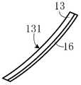
- a see-through light guiding element 13further has a convex surface 132 disposed opposite the concave surface 131, and the third light 151 containing external image information transmitted through the convex surface 132 and the concave surface 131 of the see-through light guiding element 13 enters the user.
- the left eye 14is similarly shaped, and the other see-through light guiding element further has a convex surface disposed opposite to the concave surface thereof, and the third light containing the external image information transmitted through the convex surface and the concave surface of the see-through light guiding element enters the right side of the user.
- the usercan see the real scene of the outside world, thereby forming a visual experience of mixing the 3D virtual scene and the real scene.
- the other surface of each of the see-through light guiding elements disposed opposite to the concave surfaceincludes, but is not limited to, a convex shape, in order to block the image information including the external image.
- the third lightenters the user's eyes, that is, the user avoids the real scene of the outside world.
- the other surface of the see-through light guiding element 13 opposite to the concave surface 131may be plated or affixed with shading.
- Layer 16as shown in FIG.
- a hood 171 for blocking the inclusion of the third light containing external image information into the eyes of the usermay also be disposed on the head frame 17, so that only the left eye virtual image information is transmitted by the display module.
- the first light and the second light containing the virtual image information of the right eyeenter the eyes of the user, forming a visual experience of the 3D virtual scene in the user's brain, and realizing the function of the virtual reality.
- the display module 12includes a display screen.
- the display screenmay be a display screen 18 having a spherical surface.
- the radius of curvature of the spherical surface of the display screen 18is positive, that is, the display
- the light emitting surface 181 of the screen 18is convex; as shown in FIG. 3d, the display screen may be a screen 19 having a spherical surface, and the radius of curvature of the spherical surface of the display screen 19 is negative, that is, the light emitting surface 191 of the display screen 19.
- the display screenmay also be a display screen 20 having a cylindrical surface.
- the radius of curvature of the cylinder surface of the display screen 20is positive, that is, the light emitting surface 201 of the display screen 20 is convex.
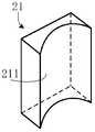
- the display screenmay also be a display screen 21 having a cylindrical surface.
- the radius of curvature of the cylinder surface of the display screen 21is negative, that is, the light emitting surface 211 of the display screen 21 is internal. Concave cylinder.
- the concave surfaces of the two see-through light guiding elementsneed to be able to The aberration of the user's eyes and the aberration caused by the tilting of the see-through light guiding element are balanced, and based on this, the concave surface of the see-through light guiding element is designed according to four special functions, as explained below.
- the face depression valuerefers to the distance of different regions of the surface of the optical element from the center point O of the surface of the optical element in the Z-axis direction.
- the optical componentrefers to a see-through light guiding component
- the surface of the optical componentrefers to a concave surface of the see-through light guiding component
- the concave shape of the concave surface of the see-through light guiding componentis sag(x, y).
- the projection point coordinate of the concave surface of the see-through light guiding element on the XY coordinate planeis (x, y).
- the concave surface of the see-through light guiding elementis designed according to the following power series polynomial function:
- cis the basic curvature of the concave and/or convex surface
- kis the basic conic coefficient of the concave and/or convex surface
- Nis the number of polynomials
- a iis the coefficient of the i-th order polynomial
- E i (x, y)is the binary power series polynomial of the standard two variables (x, y).
- the concave surface of the see-through light guiding elementis designed according to the following Chebyshev polynomial function:
- Nis the number of polynomials in the x direction
- Mis the number of polynomials in the y direction
- a ijis the coefficient of the sum of the fractional parts of the ij order polynomial, with Is the normalized coordinates after redefining the x and y coordinates to the interval [-1, 1];
- )is the maximum value of x absolute values
- )is the maximum value of y absolute values
- the concave surface of the see-through light guiding elementis designed according to the following standard Zernike polynomial function:
- cis the basic curvature of the concave and/or convex surface
- kis the basic conic coefficient of the concave and/or convex surface
- a iis the coefficient of the i-th order aspheric variable
- Nis the number of standard Zernike polynomials
- ⁇ And ⁇are the polar coordinates corresponding to the x coordinate and the y coordinate, respectively
- the interval range of ⁇is [0, 1]
- the interval range of ⁇is [0, 2 ⁇ ]. It is the i-th standard Zernike polynomial.
- the concave surface of the see-through light guiding elementis designed according to the following Anamorphic function:
- c xis the basic curvature of the concave and/or convex surface in the x direction
- k xis the basic conic coefficient of the concave and/or convex surface in the x direction
- c yis the concave and/or convex surface in the y direction
- the basic curvature, k yis the basic conic coefficient of the concave and/or convex surface in the y direction
- ⁇ 4is the fourth higher order coefficient of axial symmetry
- ⁇ 4is the fourth higher order coefficient of axial asymmetry
- ⁇ 6is the sixth higher order coefficient of axial symmetry
- ⁇ 6is the sixth higher order coefficient of axial asymmetry
- ⁇ 8is the eighth higher order coefficient of axial symmetry
- ⁇ 8is the eighth highest of axial asymmetry.
- the order factor, ⁇ 10is the 10th higher order coefficient of axial symmetry
- ⁇ 10is the 10th higher order coefficient of axial asymmetry.
- the optical elementrefers to a see-through light guiding element
- the surface of the optical elementrefers to a convex surface of the see-through light guiding element
- the concave shape of the convex surface of the see-through light guiding elementis Sag(x, y), as shown in Fig.
- the projection point coordinate of the convex surface of the see-through light guiding element on the XY coordinate planeis (x, y), in order to ensure that the third light containing the external image information enters the user's eyes
- the convex surface of the see-through light guiding elementis designed according to any one of the power series polynomial function, the Chebyshev polynomial function, the standard Zernike polynomial function, and the Anamorphic function.
- a diopter correcting lens 16is disposed between the human eye and the see-through light guiding element 13, the diopter correcting lens 16 being disposed perpendicular to the horizontal plane.
- the plane of the diopter correction lensmay also be at an angle of 30 degrees to 90 degrees from the horizontal plane.
- different degrees of diopter correcting lensesmay be arbitrarily set.
- the display module 12emits a first light ray 121 including left-eye virtual image information, a first light ray 121 reflected through the concave surface 131 of the fluoroscopic light guiding element 13, and a convex surface 132 and a concave surface 131 transmitted through the fluoroscopic light guiding element 13
- the third light ray 151 of the image informationpasses through the refractive correction lens 16 before entering the left eye 14 of the user.
- the refractive correction lens 16is a concave lens, and the first light 121 and the third light 151 passing therethrough are diverged, so that the focus of the first light 121 and the third light 151 on the left eye 14 are shifted back.
- the refractive correction lens 16can also be a convex lens that converges the first light ray 121 and the third light ray 151 thereon to advance the focus of the first light ray 121 and the third light 151 on the left eye 14.
- the display moduleemits a second light containing the virtual image information of the right eye, the second light reflected through the concave surface of the other see-through light guiding element, and the external image information transmitted through the convex and concave surfaces of the see-through light guiding element.
- the lensis first corrected by a diopter.
- the user's eyeballis the apex, and the user's eyeball is formed on both sides of the virtual display area of the virtual image seen through the see-through light guiding element 13.
- Diagonal field of viewThe distance from the farthest end of the head frame to the contact position with the foremost end of the head is c, and the distance length of the c can be adjusted as needed.
- the angular extent of the diagonal field of view regionis inversely proportional to the distance from the most distal end of the head frame 11 to the contact position with the foremost end of the head.
- the distance from the farthest end of the head frame to the contact position with the foremost end of the headis less than 80 mm under the premise that the diagonal field of view area is greater than 55 degrees.
- the second display module 12is connected to the main board 17 by a cable.
- the main board 17is also provided with a video interface and a power interface.
- the video interfaceis used to connect a computer, a mobile phone, or other device to receive a video signal.
- the video interfacemay be: hmdi, display port, thunderbolt or usb type-c, micro Usb, MHL (Mobile High-Definition Link) and other interfaces.
- the processoris configured to decode the video signal transmission and display it on the display module 12.
- the power interfaceincludes a USB interface or other interfaces.
- the reality display systemincludes only the headgear frame 11, the two display modules 12, the two see-through light guiding elements 13 and the main board 17, as described above, all 3D virtual scene rendering, image generation corresponding to both eyes are enhanced and enhanced.
- the reality display systemis connected to an external device.
- the external deviceincludes: a computer, a mobile phone, a tablet computer, and the like.
- the augmented reality display systemreceives the video signal of the external device through the video interface, and displays it on the display module 12 after decoding.
- the interaction with the useris performed by an application software on an external device such as a computer, a mobile phone, a tablet computer, etc., and can interact with the augmented reality display system by using a mouse keyboard, a touch pad or a button on the external device.
- Examples of such basic structuresinclude, but are not limited to, large screen portable displays.
- the augmented reality display systemcan project the display screen at a fixed location within the user's field of view. The user needs to adjust the size, position, and the like of the projection screen through software on the device connected to the augmented reality display system.
- the augmented reality display systemreflects the first ray including the left-eye virtual image information and the second ray including the right-eye virtual image information by the concave surfaces of the two fluoroscopic light guiding elements.
- the user's eyesare entered, thereby forming a visual experience of the 3D virtual scene in the user's brain, and the visual area is large.
- a plurality of sensorsare disposed to perform sensing on the surrounding environment.
- the present inventionprovides an augmented reality display system.
- the augmented reality display systemhas a total weight of less than 350 grams, and includes a head frame 21, two display modules 22, two see-through light guiding elements 23, and a main board 24.
- the display module 22, the see-through light guiding element 23 and the main board 24are all disposed on the head frame 21.
- the head frame 21fixes the display module 22, the see-through light guiding element 23 and the main board 24.
- the display module 22is disposed on the upper side of the see-through light guiding element 23, and the light emitted by the display module 22 can be reflected by the see-through light guiding element 23.
- the main board 24, the main board 24is located between the two display modules 22, the main board A processor is provided 24 for processing the virtual image signal and displaying the virtual image information on the display module 22.
- the head frame 21, the two display modules 22, the two see-through light guiding elements 23, the main board 24 and the head frame 11 described in the first embodiment, the two display modules 12, the two see-through light guiding elements 13, and the main board 17The specific functions, structures, and positional relationships are the same and will not be described here.
- a diopter correcting lensis disposed between the human eye and the see-through light guiding element 23, the diopter correcting lens being disposed perpendicular to the horizontal plane.
- different degrees of diopter correcting lensesmay be arbitrarily set.
- the head frame 21is further provided with a monocular camera 211, a binocular/multi-view camera 212, an eyeball tracking camera 213, a gyroscope 214, an accelerometer 215, a magnetometer 216, a depth of field sensor 217, an ambient light sensor 218, and/or a distance. Sensor 219.
- the monocular camera 211, the binocular/multi-view camera 212, the eyeball tracking camera 213, the gyroscope 214, the accelerometer 215, the magnetometer 216, the depth of field sensor 217, the ambient light sensor 218, and/or the distance sensor 219are all electrically connected to the main board 24 on.
- the monocular camera 211is a color monocular camera placed at the front of the head frame 21.
- the monocular camera 211faces the other side with respect to the user's face, and the camera can be used for photographing.
- the augmented reality display systemcan be used to locate the use of the camera using a computer vision technology to detect known locations in the environment.
- the monocular camera 211can also be a high-resolution camera for taking photos or taking video; the captured video can also be superimposed by software to superimpose the virtual object seen by the user, and the user can see through the augmented reality display system. content.
- the binocular/multi-view camera 212may be a monochrome or color camera disposed on the front or side of the head frame 21 and located on one side, two sides or all sides of the monocular camera 211. Further, the binocular/multi-view camera 212 may be provided with an infrared filter. Using the binocular camera, you can further obtain the depth of field information on the image based on the environment image. With a multi-camera camera, you can further expand the camera's viewing angle to get more ambient image and depth of field information.
- the ambient image and distance information captured by the dual/multi-view camera 212can be used to: (1) fuse with the data of the gyroscope 214, the accelerometer 215, and the magnetometer 216 to calculate the pose of the augmented reality display system. (2) Capture user gestures, palm prints, etc. for human-computer interaction.
- each of the above-mentioned monocular camera or binocular/multi-view cameramay be one of an RGB camera, a monochrome camera or an infrared camera.
- the eyeball tracking camera 213is disposed on one side of the see-through light guiding element 23, and when the user wears the augmented reality display system, the eyeball tracking camera 213 faces the side opposite to the user's face.
- the eyeball tracking camera 213is used to track the focus of the human eye, and to track and specialize the specific parts in the virtual object or virtual screen that the human eye is watching. For example, the specific information of the object is automatically displayed next to the object that the human eye is watching.
- the area of the human eyecan display the high-definition virtual object image, while for other areas, only the low-definition image can be displayed, which can effectively reduce the amount of image rendering calculation without affecting the user experience.
- the gyroscope 214, the accelerometer 215, and the magnetometer 216are disposed between the two display modules 22.
- the relative pose between the user's head and the initial position of the systemcan be obtained by fusing the data of the gyroscope 214, the accelerometer 215, and the magnetometer 216.
- the raw data of these sensorscan be further fused with the data of the binocular/multi-view camera 212 to obtain the position and attitude of the augmented reality display system in a fixed environment.
- the depth of field sensor 217is disposed at the front of the head frame 21, and can directly obtain depth information in the environment. Compared to the dual/multi-view camera 212, the depth of field sensor can obtain more accurate, higher resolution depth of field data. Similarly, the use of these data can be: (1) fused with the data of the gyroscope 214, the accelerometer 215, and the magnetometer 216 to calculate the pose of the augmented reality display system. (2) Capture user gestures, palm prints, etc. to interact with humans. (3) detecting three-dimensional information of objects around the user.
- the ambient light sensor 218is disposed on the head frame 21, and can monitor the intensity of ambient light in real time.
- the augmented reality display systemadjusts the brightness of the display module 22 in real time according to the change of the ambient light to ensure the consistency of the display effect under different ambient light.
- the distance sensor 219is disposed at a position where the augmented reality display system is in contact with the user's face for detecting whether the augmented reality display system is worn on the user's head. If the user removes the augmented reality display system, the power can be saved by turning off the display module 22, the processor, and the like.
- the augmented reality display systemfurther comprises: an infrared/near-infrared LED electrically connected to the main board 24, wherein the infrared/near-infrared LED is used for binocular/multiple
- the camera 212provides a light source. Specifically, the infrared/near-infrared LED emits infrared rays, and when the infrared rays reach an object acquired through the binocular/multi-view camera 212, the object reflects the infrared rays, and the photosensitive element on the binocular/multi-view camera 212 receives the reflection. The returned infrared rays are converted into electrical signals, followed by imaging processing.
- the operations that the augmented reality display system can perform when performing human-computer interactioninclude the following:
- the augmented reality display systemcan project the display screen at a fixed position within the user's field of view.
- the usercan adjust the size, position, and the like of the projection screen through sensors on the augmented reality display system.
- buttons, joysticks, touchpads, etc. on the remote controlwhich are connected to the augmented reality display system by wired or wireless means as a human-computer interaction interface.
- the device and the microphonecan be integrated by adding an audio decoding and power amplifying chip to the main board, integrating an earphone jack, an earplug, or a speaker, and allowing the user to interact with the augmented reality display system using voice.
- a video interface and a processorare provided on the motherboard.
- the augmented reality display systemincludes the headgear frame 21, the two display modules 22, the two see-through light guiding elements 23, the main board 24, and the plurality of sensors as described above, all of the 3D virtual scene renderings, corresponding eyes
- the image generation and the processing of the data acquired by the plurality of sensorscan be performed in an external device connected to the augmented reality display system.
- the external deviceincludes: a computer, a mobile phone, a tablet computer, and the like.
- the augmented reality display systemreceives the video signal of the external device through the video interface, and displays it on the display module 23 after decoding.
- the external devicereceives the data acquired by the plurality of sensors on the augmented reality display system, and performs processing to adjust the image displayed by the two eyes according to the data, and is reflected on the image displayed on the display module 23.
- the processor on the augmented reality display systemis only used to support the transmission and display of video signals and the transmission of sensor data.
- a processor with strong computing poweris disposed on the motherboard, and some or all of the computer vision algorithms are completed in the augmented reality display system.
- the augmented reality display systemreceives the video signal of the external device through the video interface, and displays it on the display module 23 after decoding.
- the external devicereceives the data acquired by a part of the sensors on the augmented reality display system, and performs processing to adjust the image displayed by the two eyes according to the sensor data, and is reflected on the image displayed on the display module 23.
- the data acquired by the remaining sensorsis on the augmented reality display system. deal with. For example, data acquired by the monocular camera 211, the binocular/multi-view camera 212, the gyroscope 214, the accelerometer 215, the magnetometer 216, and the depth of field sensor 217 are processed in an augmented reality display system.
- the data acquired by the eyeball tracking camera 213, the ambient light sensor 218, and the distance sensor 219are processed in an external device.
- the processor on the augmented reality display systemis used to support the transmission and display of video signals, the processing of part of the sensor data, and the transfer of the remaining sensor data.
- the motherboardis equipped with a high-performance processor and an image processor to perform all operations in the augmented reality display system.
- Augmented Reality displaysoperate as a stand-alone system without the need to connect an external device.
- the augmented reality display systemprocesses the data acquired by the sensor, the image displayed by the two eyes is adjusted, and is displayed on the display module 23 after being rendered.
- the processor on the augmented reality display systemis used for decoding processing and display of video signals and processing of sensor data.
- the concave surface of the see-through light guiding elementis plated with a reflective film.
- the reflective surface of the see-through light guiding element coated with the reflective filmhas a reflectance of 20% to 80%.
- the concave surface of the see-through light guiding elementis plated with a polarizing reflective film, and the polarization direction of the polarizing reflective film is The angle between the polarization directions of a light and the second light is greater than 70° and less than or equal to 90°.
- the polarization direction of the polarized reflective filmis perpendicular to the polarization directions of the first light and the second light, achieving nearly 100% reflection.
- the third light containing the external image informationis unpolarized light
- the concave surface of the see-through light guiding elementis plated with the polarizing reflective film
- the convex surface of the see-through light guiding elementis coated with an anti-reflection film.
- the concave surface of the see-through light guiding elementis provided with a pressure sensitive reflective film, and by changing the magnitude of the voltage applied to the pressure sensitive reflective film, the reflectance of the pressure sensitive reflective film can be adjusted between 0 and 100% when the pressure sensitive reflective film When the reflectivity is 100%, the augmented reality display system can realize the function of virtual reality.
- the external imageis included.
- the controllable adjustment of the transmittance of the third light of the interest, the pressure sensitive black sheetis disposed on the other surface of the see-through light guiding element disposed opposite to the concave surface, and by changing the voltage applied to the pressure sensitive black sheet, Adjust the light transmittance of the pressure sensitive black sheet.
- the display module 12is disposed at an angle of between 5° and 70° with respect to the horizontal direction; the reflected light 521 entering the upper edge of the user's left eye 14 in the first ray.
- the angle with the incident ray 522is less than 90°; the angle of the reflected ray 531 and the incident ray 532 entering the lower edge of the user's left eye 14 in the first ray is greater than 35°; the first ray entering the user's left eye 14
- the angle between the reflected light between the upper edge of the field of view and the lower edge of the field of view and the incident lightis between 35° and 90°. It should be noted that those skilled in the art can adjust the angle 2 and the angle 3 by adjusting the placement angle of the display module 12 with respect to the horizontal direction and the placement angle of the see-through light guiding element 13 according to the needs of the actual application. In order to achieve the best effect, the effective utilization of the left eye virtual image information and the right eye virtual image information is improved, and the user experience is improved.
- the augmented reality display systemreflects the first ray including the left-eye virtual image information and the second ray including the right-eye virtual image information by the concave surfaces of the two fluoroscopic light guiding elements.
- the user's eyesare entered, thereby forming a visual experience of the 3D virtual scene in the user's brain, and the visual area is large.
- a plurality of sensorsare arranged on the augmented reality display system. After the sensor senses the surrounding environment, the perceived result can be reflected in the image displayed in the display module, so that the on-site experience is better and the user experience is better.
Landscapes
- Physics & Mathematics (AREA)
- General Physics & Mathematics (AREA)
- Optics & Photonics (AREA)
Abstract
Description
Translated fromChinese本申请实施方式涉及增强现实技术领域,特别是涉及一种增强现实显示系统。The embodiments of the present application relate to the field of augmented reality technologies, and in particular, to an augmented reality display system.
增强现实显示系统是近年来发展的一项新技术,按照具体的应用主要分为VR(Virtual Reality,虚拟现实)和AR(Augmented Reality,增强现实)两种。AR的原理是在通过增强现实显示系统模拟虚拟视觉,叠加在用户正常的视觉上。目前,AR增强现实显示系统有光学透视式和视频透视式这两种实现方式,其主要区别在于光学合成装置不同。Augmented reality display system is a new technology developed in recent years. It is mainly divided into VR (Virtual Reality) and AR (Augmented Reality) according to specific applications. The principle of AR is to simulate virtual vision through an augmented reality display system, superimposed on the user's normal vision. At present, the AR augmented reality display system has two implementations of optical perspective and video perspective, the main difference being that the optical synthesis device is different.
其中,光学透视式的增强现实显示系统中的光学合成装置可以是一种部分透射、部分反射的元件,来自真实环境的光线部分通过该种元件,虚拟图像信息则投影在该种元件上,进而被其反射到用户眼中,从而合成真实和虚拟图像信息。Wherein, the optical synthesis device in the optical perspective augmented reality display system may be a partially transmissive, partially reflective component through which light from a real environment is partially projected, and virtual image information is projected onto the component. It is reflected into the eyes of the user to synthesize real and virtual image information.
在实现本申请过程中,发明人发现相关技术中至少存在如下问题:现有的增强现实显示系统的视场区域(Field of View)通常比较小,用户无法有效率地与虚拟图像信息进行互动,也无法形成3D虚拟场景的视觉,另外,现有的增强现实显示系统也存在体积重量较大,不便携带的问题。In the process of implementing the present application, the inventors have found that at least the following problems exist in the related art: the field of view of the existing augmented reality display system is usually small, and the user cannot efficiently interact with the virtual image information. It is also impossible to form a 3D virtual scene. In addition, the existing augmented reality display system also has a problem of large volume and no portable belt.
发明内容Summary of the invention
本申请实施方式主要解决的技术问题是提供一种视场区域较大、能够形成3D虚拟场景的视觉、体积小且便携带的增强现实显示系统。The technical problem to be solved by the embodiments of the present application is to provide an augmented reality display system with a large visual field area and capable of forming a 3D virtual scene with a small size and a portable belt.
为解决上述技术问题,本申请实施方式提供一种增强现实显示系统,包括:头戴框架、显示模块、两个透视型导光元件以及主板,所述显示模块、两个透视型导光元件及主板设置在头戴框架上;其中,To solve the above technical problem, an embodiment of the present invention provides an augmented reality display system, including: a head frame, a display module, two see-through light guiding elements, and a main board, the display module, two see-through light guiding elements, and The motherboard is placed on the head frame;
所述头戴框架,用于佩戴在用户的头部;The head worn frame for wearing on a user's head;
主板,所述主板上设置有处理器,所述处理器用于处理虚拟图像信息并将虚拟图像信息显示在显示模块上;a main board, the main board is provided with a processor, the processor is configured to process virtual image information and display the virtual image information on the display module;
所述显示模块,所述显示模块可拆卸或固定安装于所述头戴框架上,用于显示虚拟图像信息,并将虚拟图像信息包含在第一光线和第二光线中发射出去;The display module is detachably or fixedly mounted on the headset frame for displaying virtual image information, and transmitting the virtual image information in the first light and the second light;
所述两个透视型导光元件,每一所述透视型导光元件具有一凹面,所述凹面朝向用户的双眼设置;经由一所述透视型导光元件的凹面反射的第一光线进入用户的左眼,以及经由另一所述透视型导光元件的凹面反射的第二光线进入用户的右眼,以形成3D虚拟场景的视觉;其中,所述第一光线包含左眼虚拟图像信息,所述第二光线包含右眼虚拟图像信息。The two fluoroscopic light guiding elements each have a concave surface disposed toward the eyes of the user; the first light reflected by the concave surface of the fluoroscopic light guiding element enters the user a left eye, and a second light reflected through the concave surface of the other of the see-through light guiding elements enters the right eye of the user to form a view of the 3D virtual scene; wherein the first light includes left eye virtual image information, The second light ray includes right eye virtual image information.
本申请实施方式的有益效果是:通过两个透视型导光元件的凹面更多地将包含左眼虚拟图像信息的第一光线和包含右眼虚拟图像信息的第二光线分别反射进入用户的双眼,从而在用户的大脑中形成3D虚拟场景的视觉感受,视觉区域较大。另外,经由透视型导光元件的凸面和凹面透射的包含外界图像信息的第三光线进入用户的双眼,用户能够看到外界的真实场景,从而形成混合3D虚拟场景和真实场景的视觉感受。The beneficial effect of the embodiment of the present application is that the first ray including the left-eye virtual image information and the second ray including the right-eye virtual image information are respectively reflected into the eyes of the user through the concave surfaces of the two fluoroscopic light guiding elements. Thus, a visual experience of a 3D virtual scene is formed in the user's brain, and the visual area is large. In addition, the third light containing the external image information transmitted through the convex and concave surfaces of the see-through light guiding element enters the eyes of the user, and the user can see the real scene of the outside world, thereby forming a visual feeling of mixing the 3D virtual scene and the real scene.
一个或多个实施例通过与之对应的附图中的图片进行示例性说明,这些示例性说明并不构成对实施例的限定,附图中具有相同参考数字标号的元件表示为类似的元件,除非有特别申明,附图中的图不构成比例限制。The one or more embodiments are exemplified by the accompanying drawings in the accompanying drawings, and FIG. The figures in the drawings do not constitute a scale limitation unless otherwise stated.
图1a是本申请实施例一提供的一种增强现实显示系统的结构示意图;1a is a schematic structural diagram of an augmented reality display system according to
图1b是图1a所示的透视型导光元件设置在头戴框架上时的示意图;Figure 1b is a schematic view of the see-through light guiding element shown in Figure 1a when it is placed on the head frame;
图1c是图1a所示的显示模块的侧视角度与显示亮度之间的第一关系图;Figure 1c is a first relationship diagram between a side view angle and a display brightness of the display module shown in Figure 1a;
图1d是图1a所示的显示模块的侧视角度与显示亮度之间的第二关系图;Figure 1d is a second relationship diagram between the side view angle and the display brightness of the display module shown in Figure 1a;
图1e是图1a所示的显示模块的侧视角度与显示亮度之间的第三关系图;Figure 1e is a third relationship diagram between a side view angle and a display brightness of the display module shown in Figure 1a;
图2a是佩戴图1a所示的增强现实显示系统时显示模块与用户脸部的位置关系示意图;2a is a schematic diagram showing the positional relationship between the display module and the user's face when the augmented reality display system shown in FIG. 1a is worn;
图2b是旋转图1a所示的显示模块的示意图;Figure 2b is a schematic view showing the rotation of the display module shown in Figure 1a;
图3是图1a所示的增强现实显示系统的成像原理示意图;3 is a schematic diagram of an imaging principle of the augmented reality display system shown in FIG. 1a;
图3a是图1a中所示设有遮光层的透视型导光元件的结构示意图;3a is a schematic structural view of a see-through light guiding element provided with the light shielding layer shown in FIG. 1a;
图3b是本实用新型实施例提供的一种增强现实显示系统的结构示意图;FIG. 3b is a schematic structural diagram of an augmented reality display system according to an embodiment of the present invention; FIG.
图3c是显示模块中显示屏一实施例的结构示意图;3c is a schematic structural view of an embodiment of a display screen in a display module;
图3d是显示模块中显示屏又一实施例的结构示意图;Figure 3d is a schematic structural view of still another embodiment of the display screen in the display module;
图3e是显示模块中显示屏又一实施例的结构示意图;3e is a schematic structural view of still another embodiment of a display screen in a display module;
图3f是显示模组中显示屏又一实施例的结构示意图;Figure 3f is a schematic structural view of still another embodiment of the display screen in the display module;
图4是用于介绍凹面的面型凹陷值所作出的透视型导光元件剖视图;Figure 4 is a cross-sectional view of a see-through light guiding member for introducing a concave shape of a concave surface;
图4a是用于介绍面型凹陷值所作出的透视型导光元件俯视图;Figure 4a is a plan view of a see-through light guiding element for introducing a surface recess value;
图4b是用于介绍凸面的面型凹陷值所作出的透视型导光元件剖视图;Figure 4b is a cross-sectional view of the see-through light guiding element for introducing the concave value of the convex surface;
图5是图1a所示的增强现实显示系统设置屈光度矫正镜片时的示意图;Figure 5 is a schematic view of the augmented reality display system of Figure 1a when a diopter correction lens is provided;
图6是图1a所示的增强现实显示系统对角线视场区域与头部框架的最远端到用户头部最前端的距离关系的示意图;6 is a schematic diagram showing the distance relationship between the diagonal field of view area and the farthest end of the head frame to the foremost end of the user's head of the augmented reality display system shown in FIG. 1a;
图7是图1a所示的增强现实显示系统连接外接设备工作时的示意图;7 is a schematic diagram of the augmented reality display system shown in FIG. 1a connected to an external device;
图8是本申请实施例二提供的一种增强现实显示系统的结构示意图;8 is a schematic structural diagram of an augmented reality display system according to
图9是图8所示的增强现实显示系统连接外接设备工作时的示意图;9 is a schematic diagram of the augmented reality display system shown in FIG. 8 connected to an external device;
图10是图8所示的增强现实显示系统连接外接设备工作时的又一示意图;10 is another schematic diagram of the augmented reality display system shown in FIG. 8 when the external device is connected to work;
图11是图8所示的增强现实显示系统工作时的示意图。Figure 11 is a schematic illustration of the augmented reality display system of Figure 8 in operation.
图12是图1a中所示增强现实显示系统部分结构的摆放角度、光线反射示意图。Figure 12 is a schematic view showing the arrangement angle and light reflection of the partial structure of the augmented reality display system shown in Figure 1a.
为了使本申请的目的、技术方案及优点更加清楚明白,以下结合附图及实施例,对本申请进行进一步详细说明。应当理解,此处所描述的具体实施例仅用以解释本申请,并不用于限定本申请。In order to make the objects, technical solutions, and advantages of the present application more comprehensible, the present application will be further described in detail below with reference to the accompanying drawings and embodiments. It is understood that the specific embodiments described herein are merely illustrative of the application and are not intended to be limiting.
此外,下面所描述的本申请各个实施方式中所涉及到的技术特征只要彼此之间未构成冲突就可以相互组合。Further, the technical features involved in the various embodiments of the present application described below may be combined with each other as long as they do not constitute a conflict with each other.
实施例一
参阅图1a,本申请实施例提供的一种增强现实显示系统,所述增强现实显示系统的总重量小于350克,其包括:头戴框架11、两个显示模块12、两个透视型导光元件13。其中,透视型导光元件13是一种部分透射、部分反射的光学合成装置。Referring to FIG. 1a, an augmented reality display system provided by an embodiment of the present application has a total weight of less than 350 grams, including: a
所述显示模块12及透视形导光元件13皆设置在头戴框架11上,支架11将显示模块12及透视形导光元件13进行固定。显示模块12设置在透视形导光元件13的上侧,显示模块12发出的光线能够经过透视形导光元件13后发生反射。可选地,所述显示模块12还可位于所述透视型导光元件13的侧方。The
所述增强现实显示系统还包括:主板17,主板17设置在头戴框架11上,且位于二显示模块12之间。所述主板17上设置有处理器,所述处理器用于处理虚拟图像信号并将虚拟图像信息显示在显示模块12上。The augmented reality display system further includes a
本申请实施例中,头戴框架11用于佩戴在用户的头部,每一透视型导光元件13具有一凹面,凹面朝向用户的双眼设置。经由一透视型导光元件13的凹面反射的第一光线进入用户的左眼,以及经由另一透视型导光元件13的凹面反射的第二光线用户的右眼,以在用户的头脑中形成3D虚拟场景的视觉。其中,第一光线是由显示模块12发射的,且第一光线包含左眼虚拟图像信息,第二光线是由显示模块12发射的,且第二光线包含右眼虚拟图像信息。In the embodiment of the present application, the
参阅图1b,两个透视型导光元件13设置在头戴框架11上,分别独立地嵌入到头戴框架11上。可选地,可在制作透视型导光元件的原材料上设置两个对应于用户左右眼的区域,所述区域的形状大小与上述的独立设置时的每一透视型导光元件13的形状大小相同;最终的效果为一块大的透视型导光元件上设置有两个对应于用户左右眼的区域。可以理解为在一块大的透视型导光元件的原材料上加工出两个与独立设置时的透视型导光元件13的形状大小相同的区域,即两个透视型导光元件13一体成型。所述设置有对应于用户左右眼区域的透视型导光元件嵌入到头戴框架11上。Referring to FIG. 1b, two see-through
需要说明的是,显示模块12可拆卸安装于头戴框架11上,比如,显示模块为手机、平板电脑等智能显示终端;或者,显示模块固定安装于头戴框架上,比如,显示模块与头戴框架集成设计。It should be noted that the
头戴框架11上可以安装两个显示模块12,用户的左眼和右眼分别对应地设置一个显示模块12,例如,一个显示模块12用于发射包含左眼虚拟图像信息的第一光线,另一个显示模块12用于发射包含右眼虚拟图像信息的第二光线。两个显示模块12可以分别一一对应地位于两个透视型导光元件13的上方,当增强现实显示系统佩戴在用户的头部时,两个显示模块12分别一一对应地位于用户的左眼和右眼的上方;显示模块12也可以位于透视型导光元件的侧方,即两个透视型导光元件位于两个显示模块之间,当增强现实显示系统佩戴在用户的头部时,两个显示模块分别一一对应地位于用户的左眼和右眼的侧方。Two
头戴框架11上也可以安装单个显示模块12,该单个显示模块12上有两个显示区域,一个显示区域用于发射包含左眼虚拟图像信息的第一光线,另一个显示区域用于发射包含右眼虚拟图像信息的第二光线。A
显示模块包括但不限于LCD(Liquid Crystal Display,液晶显示器)、OLED(Organic Light-Emitting Diode,有机发光二极管)、LCOS(Liquid Crystal On Silicon,硅基液晶)等类型的显示器。The display module includes, but is not limited to, an LCD (Liquid Crystal Display), an OLED (Organic Light-Emitting Diode), an LCOS (Liquid Crystal On Silicon), or the like.
头戴框架可以是用于挂在用户耳部和鼻梁部的眼镜式的框架结构,也可以是用于佩戴在用户头顶和鼻梁部的头盔式框架结构。本实用新型实施例中,由于头戴框架的主要作用是用来佩戴在用户的头部以及为显示模块、透视型导光元件等光、电元器件提供支撑,头戴框架包括但不限于上述方式,在具备上述主要作用的前提下,本领域技术人员能够根据实际应用的需要对头戴框架作出若干变形。The headgear frame may be a spectacle frame structure for hanging on the ear and nose of the user, or a helmet frame structure for wearing on the top and nose of the user's head. In the embodiment of the present invention, since the main function of the headwear frame is to be worn on the user's head and to provide support for the optical and electrical components such as the display module and the see-through light guiding component, the head frame includes but is not limited to the above. In a manner, with the above-mentioned main effects, those skilled in the art can make some modifications to the head frame according to the needs of practical applications.
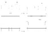
参阅图1c,图中的横向轴标识侧视角度,纵向轴表示显示亮度。显示模块12为LCD时,显示模块12的亮度是随着观察者的角度来变化的。对于普通LCD,在显示亮度为50%时的侧观察角度θ一般都比较大。Referring to Figure 1c, the horizontal axis represents the side view angle and the vertical axis represents the display brightness. When the
LCD应用于对于增强现实显示系统时,则比较适用于小的侧观察角度,这样的显示模块12的亮度就会集中在靠近中心的角度区域。因为增强现实显示系统主要使用靠近中心的角度区域,这样的话投影到用户眼中的第一光线及第二光线的亮度会比较高。参阅图1d,应用于增强现实显示系统中的LCD发出的第一光线及第二光线的亮度在显示亮度为50%时的侧观察角度θ一般都比较小。并且,应用于增强现实显示系统中的LCD发出的第一光线及第二光线的亮度的分布关于0度侧视角左右对称,且侧视角度小于60度。即是,用户视角垂直于显示模块12时,显示模块12发出的第一光线及第二光线的亮度的显示亮度为最大,用户视角向两侧偏移时,显示亮度逐渐减小,在侧视角小于60度时,显示亮度为0。When the LCD is applied to an augmented reality display system, it is more suitable for a small side viewing angle, and the brightness of such a
可选地,参阅图1e,应用于增强现实显示系统的LCD的发出的第一光线及第二光线的亮度分布可不关于0度侧视角对称,且显示亮度最亮时的侧视角度不为0度。Optionally, referring to FIG. 1e, the brightness distribution of the first light and the second light emitted by the LCD applied to the augmented reality display system may not be symmetric with respect to the 0 degree side view, and the side view angle when the brightness is the brightest is not 0. degree.
参阅图2a,两个显示模块12分别一一对应地位于两个透视型导光元件13的上方,用户佩戴上所述增强现实显示系统时,显示模块12与用户头部的正平面形成一夹角a,所述夹角a的角度为0度至180度,优选为钝角。同时,显示模块12在水平面上的投影与正平面垂直。Referring to FIG. 2a, two
参阅图2b,在某些实例中,透视形导光元件13的位置可以绕与水平面垂直的某一转轴旋转一定角度b,所述角度b的角度为0度至180度,优选为0度至90度。同时,对应左眼和右眼的透视型导光元件13可以通过头戴框架11上的机械结构调整间距,以适应不同用户的瞳距,保证使用时的舒适度和成像质量。所述两个透视型导光元件13的边缘之间的最远距离小于150毫米,即对应于左眼设置的透视型导光元件13的左边缘到对应于右眼设置的透视型导光元件13的右边缘的距离小于150毫米。相应的,显示模块12之间通过机械结构连接,所述显示模块12之间的距离也可以进行调整,或者通过调整显示内容在显示模块12上的位置达到同样的效果。Referring to FIG. 2b, in some examples, the position of the see-through light guiding
头戴框架11可以是用于挂在用户耳部和鼻梁部的眼镜式的框架结构,其上设置有鼻托111和镜腿112,通过鼻托111与镜腿112固定在用户的头部,所述镜腿112为可折叠结构,其中鼻托111对应固定在用户的鼻梁上,镜腿112对应固定在用户的耳朵上。进一步的,眼镜腿112之间还可以通过松紧带相连,佩戴时松紧带收紧眼镜腿,帮助框架在头部的固定。The
可选地,鼻托111和镜腿112为可伸缩机构,可分别调整鼻托111的高度和镜腿112的伸缩长度。同样,鼻托111和镜腿112还可以为可拆卸结构,拆卸后可对鼻托111或者镜腿112进行更换。Optionally, the
可选地,头戴框架11可包括鼻托和伸缩皮筋,通过鼻托与伸缩皮筋固定在用户头部;或者仅包括伸缩皮筋,通过所述伸缩皮筋固定在用户头部。可选地,头戴框架11也可以是用于佩戴在用户头顶和鼻梁部的头盔式框架结构。本申请实施例中,由于头戴框架11的主要作用是用来佩戴在用户的头部以及为显示模块12、透视型导光元件13等光、电元器件提供支撑,头戴框架包括但不限于上述方式,在具备上述主要作用的前提下,本领域技术人员能够根据实际应用的需要对头戴框架做出若干变形。Alternatively, the
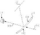
参阅图3,显示模块12发射包含左眼虚拟图像信息的第一光线121,经由一透视型导光元件13的凹面131反射的第一光线121进入用户的左眼14;同理,显示模块发射包含右眼虚拟图像信息的第二光线,经由另一透视型导光元件的凹面反射的第二光线进入用户的右眼,从而在用户的大脑中形成3D虚拟场景的视觉感受,另外,不同于谷歌眼镜中通过在用户的右眼前直接设置一块小型显示屏的方式,导致视觉区域较小,本申请实施例中,通过两个透视型导光元件反射更多的显示模块发射的第一光线和第二光线分别进入用户的双眼,视觉区域较大。Referring to FIG. 3, the
在本申请实施例中,当增强现实显示系统实现增强现实的功能,每一透视型导光元件13还具有一与凹面相背设置的凸面;经由透视型导光元件13的凸面和凹面透射的包含外界图像信息的第三光线进入用户的双眼,以形成混合3D虚拟场景和真实场景的视觉。再次参阅图3a,一透视型导光元件13还具有与凹面131相背设置的凸面132,经由透视型导光元件13的凸面132和凹面131透射的包含外界图像信息的第三光线151进入用户的左眼14,同理,另一透视型导光元件还具有与其凹面相背设置的凸面,经由该透视型导光元件的凸面和凹面透射的包含外界图像信息的第三光线进入用户的右眼,用户能够看到外界的真实场景,从而形成混合3D虚拟场景和真实场景的视觉感受。In the embodiment of the present application, when the augmented reality display system realizes the function of augmented reality, each of the see-through
在本实用新型实施例中,当头戴式显示器实现虚拟现实的功能,每一透视型导光元件的与凹面相背设置的另一表面包括但不限于凸面形状,为了阻挡包含外界图像信息的第三光线进入用户的双眼,即避免用户看到外界的真实场景,如图3a所示,可以在透视型导光元件13的与凹面131相背设置的另一表面上镀有或者粘贴有遮光层16;如图3b所示,也可以在头戴框架17上设置用于阻挡包含外界图像信息的第三光线进入用户的双眼的遮光罩171,仅使得显示模块发射的包含左眼虚拟图像信息的第一光线以及包含右眼虚拟图像信息的第二光线进入用户的双眼,在用户的大脑中形成3D虚拟场景的视觉感受,实现虚拟现实的功能。In the embodiment of the present invention, when the head mounted display realizes the function of the virtual reality, the other surface of each of the see-through light guiding elements disposed opposite to the concave surface includes, but is not limited to, a convex shape, in order to block the image information including the external image. The third light enters the user's eyes, that is, the user avoids the real scene of the outside world. As shown in FIG. 3a, the other surface of the see-through light guiding
在本实用新型实施例中,显示模块12包括显示屏,如图3c所示,所述显示屏可以是面型为球面的显示屏18,该显示屏18的球面的曲率半径为正,即显示屏18的发光表面181为凸面;如图3d所示,所述显示屏可以是面型为球面的显示屏19,该显示屏19的球面的曲率半径为负,即显示屏19的发光表面191为凹面;如图3e所示,所述显示屏也可以是面型为柱面的显示屏20,该显示屏20的柱面的曲率半径为正,即显示屏20的发光表面201为外凸的柱面;如图3f所示,所述显示屏也可以是面型为柱面的显示屏21,该显示屏21的柱面的曲率半径为负,即显示屏21的发光表面211为内凹的柱面。In the embodiment of the present invention, the
为了实现加载在显示模块发射的第一光线和第二光线中的左眼虚拟图像信息和右眼虚拟图像信息高质量地呈现在用户的双眼视网膜上,两个透视型导光元件的凹面需要能够平衡用户的双眼自带的像差、透视型导光元件倾斜拜访所带来的像差等,基于此,根据四种特殊函数来设计透视型导光元件的凹面,说明如下。In order to realize that the left-eye virtual image information and the right-eye virtual image information loaded in the first light and the second light emitted by the display module are present on the user's binocular retina with high quality, the concave surfaces of the two see-through light guiding elements need to be able to The aberration of the user's eyes and the aberration caused by the tilting of the see-through light guiding element are balanced, and based on this, the concave surface of the see-through light guiding element is designed according to four special functions, as explained below.
如图4所示,在光学概念中,面型凹陷值是指光学元件表面的不同区域在Z轴方向上距离光学元件表面的中心点O的距离。本实用新型实施例中,光学元件是指透视型导光元件,光学元件表面是指透视型导光元件的凹面,透视型导光元件的凹面的面型凹陷值是sag(x,y),如图4所示,透视型导光元件的凹面在XY坐标面上的投影点坐标是(x,y)。As shown in FIG. 4, in the optical concept, the face depression value refers to the distance of different regions of the surface of the optical element from the center point O of the surface of the optical element in the Z-axis direction. In the embodiment of the present invention, the optical component refers to a see-through light guiding component, the surface of the optical component refers to a concave surface of the see-through light guiding component, and the concave shape of the concave surface of the see-through light guiding component is sag(x, y). As shown in FIG. 4, the projection point coordinate of the concave surface of the see-through light guiding element on the XY coordinate plane is (x, y).
一、透视型导光元件的凹面根据如下幂级数多项式函数设计:1. The concave surface of the see-through light guiding element is designed according to the following power series polynomial function:

其中,c是所述凹面和/或凸面的基本曲率,k是所述凹面和/或凸面的基本圆锥系数,N是多项式的数量,Ai是第i阶多项式的系数,Ei(x,y)是标准的两个变量(x,y)的二元幂级数多项式。Where c is the basic curvature of the concave and/or convex surface, k is the basic conic coefficient of the concave and/or convex surface, N is the number of polynomials, Ai is the coefficient of the i-th order polynomial, Ei (x, y) is the binary power series polynomial of the standard two variables (x, y).

二、透视型导光元件的凹面根据如下Chebyshev多项式函数设计:2. The concave surface of the see-through light guiding element is designed according to the following Chebyshev polynomial function:
其中,c是所述凹面和/或凸面的基本曲率,N是x方向多项式的数量,M是y方向多项式的数量,aij是第ij阶多项式分部总和的系数,


三、透视型导光元件的凹面根据如下标准Zernike多项式函数设计:3. The concave surface of the see-through light guiding element is designed according to the following standard Zernike polynomial function:

其中,c是所述凹面和/或凸面的基本曲率,k是所述凹面和/或凸面的基本圆锥系数,ai是第i阶非球面变量的系数,N是标准Zernike多项式的数量,ρ和φ分别是x坐标和y坐标相对应的极坐标,ρ的区间范围是[0,1],φ的区间范围是[0,2π]。
四、透视型导光元件的凹面根据如下Anamorphic函数设计:4. The concave surface of the see-through light guiding element is designed according to the following Anamorphic function:

其中,cx是所述凹面和/或凸面在x方向的基本曲率,kx是所述凹面和/或凸面在x方向的基本圆锥系数,cy是所述凹面和/或凸面在y方向的基本曲率,ky是所述凹面和/或凸面在y方向的基本圆锥系数,α4是轴向对称的第4高阶系数,β4是轴向不对称的第4高阶系数,α6是轴向对称的第6高阶系数,β6是轴向不对称的第6高阶系数,α8是轴向对称的第8高阶系数,β8是轴向不对称的第8高阶系数,α10是轴向对称的第10高阶系数,β10是轴向不对称的第10高阶系数。Wherein cx is the basic curvature of the concave and/or convex surface in the x direction, kx is the basic conic coefficient of the concave and/or convex surface in the x direction, and cy is the concave and/or convex surface in the y direction The basic curvature, ky is the basic conic coefficient of the concave and/or convex surface in the y direction, α4 is the fourth higher order coefficient of axial symmetry, and β4 is the fourth higher order coefficient of axial asymmetry, α6 is the sixth higher order coefficient of axial symmetry, β6 is the sixth higher order coefficient of axial asymmetry, α8 is the eighth higher order coefficient of axial symmetry, and β8 is the eighth highest of axial asymmetry. The order factor, α10 is the 10th higher order coefficient of axial symmetry, and β10 is the 10th higher order coefficient of axial asymmetry.
如图4b所示,在上述光学概念中,光学元件是指透视型导光元件,光学元件表面是指透视型导光元件的凸面,透视型导光元件的凸面的面型凹陷值是sag(x,y),如图4a所示,透视型导光元件的凸面在XY坐标面上的投影点坐标是(x,y),为了保证包含外界图像信息的第三光线进入用户的双眼时,减少受到的干扰,根据上述幂级数多项式函数、Chebyshev多项式函数、标准Zernike多项式函数、Anamorphic函数中任一一种函数来设计透视型导光元件的凸面。As shown in FIG. 4b, in the above optical concept, the optical element refers to a see-through light guiding element, and the surface of the optical element refers to a convex surface of the see-through light guiding element, and the concave shape of the convex surface of the see-through light guiding element isSag(x, y), as shown in Fig. 4a, the projection point coordinate of the convex surface of the see-through light guiding element on the XY coordinate plane is (x, y), in order to ensure that the third light containing the external image information enters the user's eyes When the interference is reduced, the convex surface of the see-through light guiding element is designed according to any one of the power series polynomial function, the Chebyshev polynomial function, the standard Zernike polynomial function, and the Anamorphic function.
参阅图5,可选地,在人眼与透视型导光元件13之间设置一屈光度矫正镜片16,所述屈光度矫正镜片16垂直于水平面设置。可选地,所述屈光度矫正镜片所在平面也可与水平面成30度到90度的夹角。可选地,可任意设置不同度数的屈光度矫正镜片。显示模块12发射包含左眼虚拟图像信息的第一光线121,经由透视型导光元件13的凹面131反射的第一光线121以及经由透视型导光元件13的凸面132和凹面131透射的包含外界图像信息的第三光线151进入用户的左眼14之前,先经过屈光矫正镜片16。所述屈光矫正镜片16为凹透镜,使经过其上的第一光线121以及第三光线151发散,使第一光线121以及第三光线151在左眼14上的焦点后移。同样,所述屈光矫正镜片16还可为凸透镜,使经过其上的第一光线121以及第三光线151汇聚,使第一光线121以及第三光线151在左眼14上的焦点前移。Referring to Figure 5, optionally, a
同理,显示模块发射包含右眼虚拟图像信息的第二光线,经由另一透视型导光元件的凹面反射的第二光线以及经由该透视型导光元件的凸面和凹面透射的包含外界图像信息的第三光线进入用户的右眼之前,也先经过一屈光度矫正镜片。Similarly, the display module emits a second light containing the virtual image information of the right eye, the second light reflected through the concave surface of the other see-through light guiding element, and the external image information transmitted through the convex and concave surfaces of the see-through light guiding element. Before the third light enters the user's right eye, the lens is first corrected by a diopter.
参阅图6,增强现实显示系统佩戴在用户头部上后,以用户的眼球为顶点,用户的眼球到通过所述透视型导光元件13看到的虚拟图像的虚拟显示区域的两侧边缘构成对角线视场区域。头部框架的最远端到与头部最前端接触位置的距离为c,可根据需要调节所述c的距离长度。所述对角线视场区域的角度大小与所述头部框架11的最远端到与头部最前端接触位置的距离成反比。优选地,在保证对角线视场区域大于55度的前提下,头部框架的最远端到与头部最前端接触位置的距离小于80mm。Referring to FIG. 6, after the augmented reality display system is worn on the user's head, the user's eyeball is the apex, and the user's eyeball is formed on both sides of the virtual display area of the virtual image seen through the see-through light guiding
参阅图7,二显示模块12通过电缆连接到主板17上。Referring to FIG. 7, the
主板17上还设置有视频接口以及电源接口。The
所述视频接口用于连接计算机、手机、或其他设备接收视频信号。其中所述视频接口可以为:hmdi、display port、thunderbolt或usb type-c,micro usb,MHL(Mobile High-Definition Link)等接口。The video interface is used to connect a computer, a mobile phone, or other device to receive a video signal. The video interface may be: hmdi, display port, thunderbolt or usb type-c, microUsb, MHL (Mobile High-Definition Link) and other interfaces.
所述处理器,用于解码视频信号传输并显示在显示模块12上。The processor is configured to decode the video signal transmission and display it on the
电源接口,用于外接电源或电池供电。所述电源接口包括USB接口或者其他接口。Power connector for external power or battery power. The power interface includes a USB interface or other interfaces.
当增强现实显示系统仅包括如上所述的头戴框架11、二显示模块12、两个透视型导光元件13及主板17时,所有的3D虚拟场景渲染、对应双眼的图像生成均在与增强现实显示系统相连的外接设备中进行。所述外接设备包括:计算机、手机、平板电脑等。When the augmented reality display system includes only the
具体地,增强现实显示系统通过视频接口接收外接设备的视频信号,解码后在显示模块12上显示。同时,与用户的交互通过计算机、手机、平板电脑等外接设备上的应用软件进行,可通过使用外接设备上的鼠标键盘、触摸板或按钮与所述增强现实显示系统进行交互。这种基本结构的应用实例包括但不限于大屏幕便携显示器。增强现实显示系统可以将显示屏幕投射在用户视野内的某一固定位置。用户需要通过与增强现实显示系统相连的设备上的软件进行调整投射屏幕的尺寸、位置等操作。Specifically, the augmented reality display system receives the video signal of the external device through the video interface, and displays it on the
本申请实施例提供的一种增强现实显示系统,通过两个透视型导光元件的凹面更多地将包含左眼虚拟图像信息的第一光线和包含右眼虚拟图像信息的第二光线分别反射进入用户的双眼,从而在用户的大脑中形成3D虚拟场景的视觉感受,视觉区域较大。The augmented reality display system provided by the embodiment of the present application reflects the first ray including the left-eye virtual image information and the second ray including the right-eye virtual image information by the concave surfaces of the two fluoroscopic light guiding elements. The user's eyes are entered, thereby forming a visual experience of the 3D virtual scene in the user's brain, and the visual area is large.
实施例二
参阅图8,在实施例一中提供的一种增强现实显示系统的基础上,设置多个传感器进行对周边环境进行感知。Referring to FIG. 8, on the basis of an augmented reality display system provided in the first embodiment, a plurality of sensors are disposed to perform sensing on the surrounding environment.
本实施例提供的一种增强现实显示系统,所述增强现实显示系统的总重量小于350克,其包括:头戴框架21、二显示模块22、两个透视型导光元件23及主板24。The present invention provides an augmented reality display system. The augmented reality display system has a total weight of less than 350 grams, and includes a
所述显示模块22、透视形导光元件23及主板24皆设置在头戴框架21上,头戴框架21将显示模块22、透视形导光元件23及主板24进行固定。显示模块22设置在透视形导光元件23的上侧,显示模块22发出的光线能够经过透视形导光元件23后发生反射。主板24,主板24位于二显示模块22之间,所述主板24上设置有处理器,所述处理器用于处理虚拟图像信号并将虚拟图像信息显示在显示模块22上。The
头戴框架21、二显示模块22、两个透视型导光元件23、主板24与实施例一中所述的头戴框架11、二显示模块12、两个透视型导光元件13、主板17的具体功能、结构及位置关系相同,在此不进行赘述。The
同样,在人眼与透视型导光元件23之间设置一屈光度矫正镜片,所述屈光度矫正镜片垂直于水平面设置。可选地,可任意设置不同度数的屈光度矫正镜片。Similarly, a diopter correcting lens is disposed between the human eye and the see-through light guiding element 23, the diopter correcting lens being disposed perpendicular to the horizontal plane. Alternatively, different degrees of diopter correcting lenses may be arbitrarily set.
头部框架21上还设置有单目摄像头211、双目/多目摄像头212、眼球追踪摄像头213、陀螺仪214、加速度计215、磁场计216、景深传感器217、环境光传感器218和/或距离传感器219。The
单目摄像头211、双目/多目摄像头212、眼球追踪摄像头213、陀螺仪214、加速度计215、磁场计216、景深传感器217、环境光传感器218和/或距离传感器219皆电连接在主板24上。The
具体地,所述单目摄像头211为彩色单目摄像头,放置于头部框架21的前部。用户佩戴所述增强现实显示系统时,单目摄像头211朝向相对于用户脸部的另一侧,可以使用该摄像头进行拍照。进一步的,还可以对使用该摄像头,运用计算机视觉技术检测环境中的位置已知的标记,帮助所述增强现实显示系统进行定位。Specifically, the
所述单目摄像头211还可以为高分辨率的摄像头,用于拍照或者拍摄视频;拍摄所获得的视频还可以通过软件叠加用户所见的虚拟物体,复现用户通过增强现实显示系统看到的内容。The
所述双目/多目摄像头212可以是单色或彩色的摄像头,其设置在头戴框架21前部或侧面,且位于单目摄像头211的一侧、两侧或者四周。进一步的,所述双目/多目摄像头212可以带有红外滤光片。使用双目摄像头,可以在获得环境图像的基础上,进一步得到图像上的景深信息。使用多目摄像头,则可以进一步扩展相机的视角,获得更多的环境图像与景深信息。双/多目摄像头212捕获的环境图像和距离信息可被用于:(1)与陀螺仪214、加速度计215、磁场计216的数据相融合,计算增强现实显示系统的姿态。(2)捕获用户手势、掌纹等用于人机交互。The binocular/
可选地,上述的单目摄像头或双目/多目摄像头中的每一目均可是RGB摄像头、单色摄像头或红外摄像头中的一种。Optionally, each of the above-mentioned monocular camera or binocular/multi-view camera may be one of an RGB camera, a monochrome camera or an infrared camera.
所述眼球追踪摄像头213,设置在透视型导光元件23的一侧,用户佩戴所述增强现实显示系统时,眼球追踪摄像头213朝向相对于用户脸部的一侧。所述眼球追踪摄像头213用于跟踪人眼焦点,对人眼所注视的虚拟物件或虚拟屏幕中的特定部位进行追踪和特殊处理。比如,在人眼所注视的物件旁边自动显示此物件的具体信息等。另外对人眼注视的区域可以显示高清晰度的虚拟物件图像,而对其他区域则只显示低清晰度图像即可,这样可以有效减少图像渲染的计算量,而不会影响用户体验。The
陀螺仪214、加速度计215、磁场计216设置在二显示模块22之间。可以通过融合陀螺仪214、加速度计215和磁场计216的数据,得到用户头部与系统初始位置间相对姿态。这些传感器的原始数据可以进一步和双目/多目摄像头212的数据进行融合,得到增强现实显示系统在固定环境中的位置和姿态。The gyroscope 214, the accelerometer 215, and the magnetometer 216 are disposed between the two
所述景深传感器217设置在头戴框架21的前部,可以直接获得环境中的景深信息。与双/多目摄像头212相比,景深传感器可以获得更准确、分辨率更高的景深数据。类似的,使用这些数据可以:(1)与陀螺仪214、加速度计215、磁场计216的数据相融合,计算增强现实显示系统的姿态。(2)捕获用户手势、掌纹等用与人机交互。(3)检测用户周围物体的三维信息。The depth of
所述环境光传感器218设置在头戴框架21上,可以实时监控环境光线的强弱。增强现实显示系统根据环境光的变化实时的调整显示模块22的亮度,以保证显示效果在不同环境光下的一致性。The ambient
所述距离传感器219设置在增强现实显示系统与用户面部接触的位置,用于检测增强现实显示系统是否佩戴在用户头部。若用户摘下了增强现实显示系统,则可以通过关闭显示模块22、处理器等方式节电。The distance sensor 219 is disposed at a position where the augmented reality display system is in contact with the user's face for detecting whether the augmented reality display system is worn on the user's head. If the user removes the augmented reality display system, the power can be saved by turning off the
可选地,所述增强现实显示系统还包括:红外/近红外光LED,所述红外/近红外光LED电连接在主板24上,所述红外/近红外光LED用于为双目/多目摄像头212提供光源。具体为,所述红外/近红外LED发出红外线,在红外线到达通过双目/多目摄像头212获取的物体时,所述物体将红外线反射回去,双目/多目摄像头212上的感光元件接收反射回来的红外线并转换成电信号,接着在进行成像处理。Optionally, the augmented reality display system further comprises: an infrared/near-infrared LED electrically connected to the
所述增强现实显示系统在进行人机交互时,可进行的操作包括如下:The operations that the augmented reality display system can perform when performing human-computer interaction include the following:
(1)增强现实显示系统可以将显示屏幕投射在用户视野内的某一固定位置。用户可通过增强现实显示系统上的传感器进行调整投射屏幕的尺寸、位置等操作。(1) The augmented reality display system can project the display screen at a fixed position within the user's field of view. The user can adjust the size, position, and the like of the projection screen through sensors on the augmented reality display system.
(2)可以通过各类传感器进行手势、掌纹识别,用于人机交互。(2) Gesture and palmprint recognition can be performed by various sensors for human-computer interaction.
(3)可以通过眼球追踪判断用户的意图,对人眼所观察虚拟物件或虚拟屏幕中的特定部位进行相应处理。(3) The user's intention can be judged by the eyeball tracking, and the virtual object or the specific part in the virtual screen observed by the human eye is processed accordingly.
(4)还可以在支架上增加实体或触摸按钮、摇杆等,用于人机交互。(4) It is also possible to add entities or touch buttons, rockers, etc. to the bracket for human-computer interaction.
(5)可以配有遥控器,遥控器上有按钮、摇杆、触控板等,通过有线或无线的方式与增强现实显示系统相连,作为人机交互界面。(5) It can be equipped with a remote control. There are buttons, joysticks, touchpads, etc. on the remote control, which are connected to the augmented reality display system by wired or wireless means as a human-computer interaction interface.
(6)可以通过在主板上增加音频解码和功率放大芯片,集成耳塞插孔、耳塞、或喇叭等发生设备与麦克风,允许用户使用语音与增强现实显示系统进行交互。(6) The device and the microphone can be integrated by adding an audio decoding and power amplifying chip to the main board, integrating an earphone jack, an earplug, or a speaker, and allowing the user to interact with the augmented reality display system using voice.
参阅图9,主板上设置有视频接口和处理器。Referring to Figure 9, a video interface and a processor are provided on the motherboard.
当增强现实显示系统包括如上所述的头戴框架21、二显示模块22、两个透视型导光元件23、主板24以及如上所述的多个传感器时,所有的3D虚拟场景渲染、对应双眼的图像生成以及多个传感器获取的数据的处理均可在与增强现实显示系统相连的外接设备中进行。所述外接设备包括:计算机、手机、平板电脑等。When the augmented reality display system includes the
具体地,增强现实显示系统通过视频接口接收外接设备的视频信号,解码后在显示模块23上显示。外接设备接收增强现实显示系统上的多个传感器获取的数据,进行处理后根据数据对双眼显示的图像进行调整,在显示模块23上显示的图像上进行体现。增强现实显示系统上的处理器仅用于支持视频信号的传输与显示以及传感器数据的传递。Specifically, the augmented reality display system receives the video signal of the external device through the video interface, and displays it on the display module 23 after decoding. The external device receives the data acquired by the plurality of sensors on the augmented reality display system, and performs processing to adjust the image displayed by the two eyes according to the data, and is reflected on the image displayed on the display module 23. The processor on the augmented reality display system is only used to support the transmission and display of video signals and the transmission of sensor data.
参阅图10,主板上设置有运算能力较强的处理器,将部分或全部计算机视觉算法在增强现实显示系统内完成。Referring to FIG. 10, a processor with strong computing power is disposed on the motherboard, and some or all of the computer vision algorithms are completed in the augmented reality display system.
具体地,增强现实显示系统通过视频接口接收外接设备的视频信号,解码后在显示模块23上显示。外接设备接收增强现实显示系统上的部分传感器获取的数据,进行处理后根据传感器数据对双眼显示的图像进行调整,在显示模块23上显示的图像上进行体现。其余传感器获取的数据则在增强现实显示系统上处理。例如,单目摄像头211、双目/多目摄像头212、陀螺仪214、加速度计215、磁场计216及景深传感器217获取的数据在增强现实显示系统中处理。眼球追踪摄像头213、环境光传感器218及距离传感器219获取的数据在外接设备中处理。增强现实显示系统上的处理器用于支持视频信号的传输与显示、部分传感器数据的处理以及其余传感器数据的传递。Specifically, the augmented reality display system receives the video signal of the external device through the video interface, and displays it on the display module 23 after decoding. The external device receives the data acquired by a part of the sensors on the augmented reality display system, and performs processing to adjust the image displayed by the two eyes according to the sensor data, and is reflected on the image displayed on the display module 23. The data acquired by the remaining sensors is on the augmented reality display system.deal with. For example, data acquired by the
参阅图11,主板上设置有高性能的处理器以及图像处理器,在增强现实显示系统内完成所有的运算。在这种模式下,增强现实显示无需连接外接设备,可作为一个独立的系统运行。Referring to Figure 11, the motherboard is equipped with a high-performance processor and an image processor to perform all operations in the augmented reality display system. In this mode, Augmented Reality displays operate as a stand-alone system without the need to connect an external device.
具体地,增强现实显示系统将传感器获取的数据进行处理后,对双眼显示的图像进行调整,渲染后在显示模块23上显示。增强现实显示系统上的处理器用于视频信号的解码处理与显示以及传感器数据的处理。Specifically, after the augmented reality display system processes the data acquired by the sensor, the image displayed by the two eyes is adjusted, and is displayed on the display module 23 after being rendered. The processor on the augmented reality display system is used for decoding processing and display of video signals and processing of sensor data.
在实施例一及实施例二中所述的增强现实显示系统实现增强现实的实际应用中,为了增加透视型导光元件的凹面对显示模块发射的第一光线和第二光线的反射率,例如,透视型导光元件的凹面镀有反射膜,较佳的,镀有反射膜的透视型导光元件的凹面的反射率是20%-80%。又如,若第一光线和第二光线是线偏振光,为了增加透视型导光元件的凹面的反射率,透视型导光元件的凹面镀有偏振反射膜,偏振反射膜的偏振方向与第一光线和第二光线的偏振方向之间的角度大于70°且小于等于90°,比如:偏振反射膜的偏振方向与第一光线和第二光线的偏振方向垂直,实现近乎为100%的反射率,另外,由于包含外界图像信息的第三光线是非偏振光,若透视型导光元件的凹面镀有偏振反射膜,当第三光线经由该偏振反射膜时,有近乎50%的第三光线进入用户的双眼,用户仍然能够看到外界的真实场景。为了更好地让包含外界图像信息的第三光线进入用户的双眼,透视型导光元件的凸面镀有增透膜。In the practical application of implementing the augmented reality in the augmented reality display system described in the first embodiment and the second embodiment, in order to increase the reflectivity of the first light and the second light emitted by the concave display module by the concave light guiding element, For example, the concave surface of the see-through light guiding element is plated with a reflective film. Preferably, the reflective surface of the see-through light guiding element coated with the reflective film has a reflectance of 20% to 80%. For example, if the first light and the second light are linearly polarized light, in order to increase the reflectivity of the concave surface of the see-through light guiding element, the concave surface of the see-through light guiding element is plated with a polarizing reflective film, and the polarization direction of the polarizing reflective film is The angle between the polarization directions of a light and the second light is greater than 70° and less than or equal to 90°. For example, the polarization direction of the polarized reflective film is perpendicular to the polarization directions of the first light and the second light, achieving nearly 100% reflection. In addition, since the third light containing the external image information is unpolarized light, if the concave surface of the see-through light guiding element is plated with the polarizing reflective film, when the third light passes through the polarizing reflective film, there is nearly 50% of the third light. Entering the user's eyes, the user can still see the real scene from the outside world. In order to better allow the third light containing external image information to enter the user's eyes, the convex surface of the see-through light guiding element is coated with an anti-reflection film.
在实施例一及实施例二中所述的增强现实显示系统的实际应用中,为了实现透视型导光元件的凹面对显示模块发射的第一光线和第二光线的反射率的可控调节,透视型导光元件的凹面设有压敏反射膜,通过改变加载在压敏反射膜上的电压大小,能够调节压敏反射膜的反射率位于0至100%之间,当压敏反射膜的反射率为100%时,增强现实显示系统可以实现虚拟现实的功能。In the practical application of the augmented reality display system described in the first embodiment and the second embodiment, in order to realize the controllable adjustment of the reflectance of the first light and the second light emitted by the concave display module of the see-through light guiding element The concave surface of the see-through light guiding element is provided with a pressure sensitive reflective film, and by changing the magnitude of the voltage applied to the pressure sensitive reflective film, the reflectance of the pressure sensitive reflective film can be adjusted between 0 and 100% when the pressure sensitive reflective film When the reflectivity is 100%, the augmented reality display system can realize the function of virtual reality.
为了实现透视型导光元件的与凹面相背设置的另一表面对包含外界图像信息的第三光线的透光率的可控调节,透视型导光元件的与凹面相背设置的另一表面上设有压敏黑片,通过改变加载在压敏黑片上的电压大小,能够调节压敏黑片透光率的高低。In order to realize the other surface pair of the see-through light guiding element disposed opposite to the concave surface, the external image is includedThe controllable adjustment of the transmittance of the third light of the interest, the pressure sensitive black sheet is disposed on the other surface of the see-through light guiding element disposed opposite to the concave surface, and by changing the voltage applied to the pressure sensitive black sheet, Adjust the light transmittance of the pressure sensitive black sheet.
由于人眼的生理视场中,不同区域的重要程度不同,为了能够将经由透视型导光元件的凹面反射的第一光线和第二光线进入人眼的生理视场的重要区域,较佳的,如图12所示,显示模块12相对于水平方向的摆放角度一是5°至70°之间的任一角度;第一光线中进入用户的左眼14视场上沿的反射光线521与入射光线522的角度二小于90°;第一光线中进入用户的左眼14视场下沿的反射光线531与入射光线532的角度三大于35°;第一光线中进入用户的左眼14视场上沿和视场下沿之间的反射光线与入射光线的角度在35°至90°之间。需要说明的是,本领域的技术人员能够根据实际应用的需要,通过调整显示模块12相对于水平方向的摆放角度一以及透视型导光元件13的摆放角度来调节角度二和角度三,以达到最佳效果,提高左眼虚拟图像信息和右眼虚拟图像信息的有效利用率,提升用户体验。Since the importance of different regions is different in the physiological field of view of the human eye, in order to enable the first light and the second light reflected by the concave surface of the see-through light guiding element to enter an important region of the physiological field of view of the human eye, preferably As shown in FIG. 12, the
本申请实施例提供的一种增强现实显示系统,通过两个透视型导光元件的凹面更多地将包含左眼虚拟图像信息的第一光线和包含右眼虚拟图像信息的第二光线分别反射进入用户的双眼,从而在用户的大脑中形成3D虚拟场景的视觉感受,视觉区域较大。同时在增强现实显示系统上设置多个传感器,传感器感知周边的环境后,可将感知的结果在显示模块中显示的图像中进行体现,使得临场感受更好,用户体验更佳。The augmented reality display system provided by the embodiment of the present application reflects the first ray including the left-eye virtual image information and the second ray including the right-eye virtual image information by the concave surfaces of the two fluoroscopic light guiding elements. The user's eyes are entered, thereby forming a visual experience of the 3D virtual scene in the user's brain, and the visual area is large. At the same time, a plurality of sensors are arranged on the augmented reality display system. After the sensor senses the surrounding environment, the perceived result can be reflected in the image displayed in the display module, so that the on-site experience is better and the user experience is better.
以上所述仅为本申请的实施例,并非因此限制本申请的专利范围,凡是利用本申请说明书及附图内容所作的等效结构或等效流程变换,或直接或间接运用在其他相关的技术领域,均同理包括在本申请的专利保护范围内。The above description is only the embodiment of the present application, and thus does not limit the scope of the patent application, and the equivalent structure or equivalent process transformation made by using the specification and the drawings of the present application, or directly or indirectly applied to other related technologies. The fields are all included in the scope of patent protection of this application.
Claims (34)
Translated fromChinese


Applications Claiming Priority (4)
| Application Number | Priority Date | Filing Date | Title |
|---|---|---|---|
| CN201610812210.X | 2016-09-07 | ||
| CN201610812210.XACN107797278A (en) | 2016-09-07 | 2016-09-07 | Head mounted display |
| CN201710079190.4 | 2017-02-14 | ||
| CN201710079190.4ACN108427193A (en) | 2017-02-14 | 2017-02-14 | Augmented reality display system |
Publications (1)
| Publication Number | Publication Date |
|---|---|
| WO2018045985A1true WO2018045985A1 (en) | 2018-03-15 |
Family
ID=61561720
Family Applications (1)
| Application Number | Title | Priority Date | Filing Date |
|---|---|---|---|
| PCT/CN2017/100933CeasedWO2018045985A1 (en) | 2016-09-07 | 2017-09-07 | Augmented reality display system |
Country Status (1)
| Country | Link |
|---|---|
| WO (1) | WO2018045985A1 (en) |
Cited By (4)
| Publication number | Priority date | Publication date | Assignee | Title |
|---|---|---|---|---|
| CN109298533A (en)* | 2018-12-07 | 2019-02-01 | 北京七鑫易维信息技术有限公司 | A kind of aobvious equipment of head |
| CN111522141A (en)* | 2020-06-08 | 2020-08-11 | 歌尔光学科技有限公司 | headset |
| US11412310B2 (en)* | 2020-05-18 | 2022-08-09 | Qualcomm Incorporated | Performing and evaluating split rendering over 5G networks |
| CN115396656A (en)* | 2022-08-29 | 2022-11-25 | 歌尔科技有限公司 | Augmented reality method, system, device and medium based on AR SDK |
Citations (6)
| Publication number | Priority date | Publication date | Assignee | Title |
|---|---|---|---|---|
| CN102937745A (en)* | 2012-11-13 | 2013-02-20 | 京东方科技集团股份有限公司 | Open-type head-wearing display device and display method thereof |
| CN203658670U (en)* | 2013-10-23 | 2014-06-18 | 卫荣杰 | Head-mounted see-through display apparatus |
| US8873148B1 (en)* | 2011-12-12 | 2014-10-28 | Google Inc. | Eyepiece having total internal reflection based light folding |
| CN204595328U (en)* | 2014-12-26 | 2015-08-26 | 成都理想境界科技有限公司 | Head-mounted display apparatus |
| US9366869B2 (en)* | 2014-11-10 | 2016-06-14 | Google Inc. | Thin curved eyepiece for see-through head wearable display |
| CN206497255U (en)* | 2017-02-14 | 2017-09-15 | 毛颖 | Augmented reality shows system |
- 2017
- 2017-09-07WOPCT/CN2017/100933patent/WO2018045985A1/ennot_activeCeased
Patent Citations (6)
| Publication number | Priority date | Publication date | Assignee | Title |
|---|---|---|---|---|
| US8873148B1 (en)* | 2011-12-12 | 2014-10-28 | Google Inc. | Eyepiece having total internal reflection based light folding |
| CN102937745A (en)* | 2012-11-13 | 2013-02-20 | 京东方科技集团股份有限公司 | Open-type head-wearing display device and display method thereof |
| CN203658670U (en)* | 2013-10-23 | 2014-06-18 | 卫荣杰 | Head-mounted see-through display apparatus |
| US9366869B2 (en)* | 2014-11-10 | 2016-06-14 | Google Inc. | Thin curved eyepiece for see-through head wearable display |
| CN204595328U (en)* | 2014-12-26 | 2015-08-26 | 成都理想境界科技有限公司 | Head-mounted display apparatus |
| CN206497255U (en)* | 2017-02-14 | 2017-09-15 | 毛颖 | Augmented reality shows system |
Cited By (5)
| Publication number | Priority date | Publication date | Assignee | Title |
|---|---|---|---|---|
| CN109298533A (en)* | 2018-12-07 | 2019-02-01 | 北京七鑫易维信息技术有限公司 | A kind of aobvious equipment of head |
| CN109298533B (en)* | 2018-12-07 | 2023-12-26 | 北京七鑫易维信息技术有限公司 | Head display equipment |
| US11412310B2 (en)* | 2020-05-18 | 2022-08-09 | Qualcomm Incorporated | Performing and evaluating split rendering over 5G networks |
| CN111522141A (en)* | 2020-06-08 | 2020-08-11 | 歌尔光学科技有限公司 | headset |
| CN115396656A (en)* | 2022-08-29 | 2022-11-25 | 歌尔科技有限公司 | Augmented reality method, system, device and medium based on AR SDK |
Similar Documents
| Publication | Publication Date | Title |
|---|---|---|
| CN206497255U (en) | Augmented reality shows system | |
| US11385467B1 (en) | Distributed artificial reality system with a removable display | |
| CN111602082B (en) | Position Tracking System for Head Mounted Displays Including Sensor Integrated Circuits | |
| JP6083880B2 (en) | Wearable device with input / output mechanism | |
| CN108427193A (en) | Augmented reality display system | |
| KR20210004776A (en) | Apparatus and method of displaying augmented reality | |
| CN108421252B (en) | Game realization method based on AR equipment and AR equipment | |
| WO2019001575A1 (en) | Wearable display device | |
| KR20150116814A (en) | Eye tracking wearable devices and methods for use | |
| US20160097929A1 (en) | See-through display optic structure | |
| WO2018149267A1 (en) | Display method and device based on augmented reality | |
| WO2018045985A1 (en) | Augmented reality display system | |
| US20180335635A1 (en) | Head mounted display device, control method for head mounted display device, and computer program | |
| WO2016169339A1 (en) | Image enhancing eyeglasses structure | |
| TWM512138U (en) | Vertical projection type near-eye display module | |
| CN118591753A (en) | Display system having a grating oriented to reduce the appearance of ghost images | |
| TW202317771A (en) | Compact imaging optics using spatially located, free form optical components for distortion compensation and image clarity enhancement | |
| CN116009253A (en) | Optical equipment | |
| CN107111143B (en) | Vision system and film viewer | |
| CN206638889U (en) | Head mounted display | |
| WO2016051429A1 (en) | Input/output device, input/output program, and input/output method | |
| CN204439936U (en) | A kind of video eyeglasses | |
| US20240094594A1 (en) | Gradient-index liquid crystal lens having a plurality of independently-operable driving zones | |
| TW201805689A (en) | External near-eye display device | |
| US20230185090A1 (en) | Eyewear including a non-uniform push-pull lens set |
Legal Events
| Date | Code | Title | Description |
|---|---|---|---|
| 121 | Ep: the epo has been informed by wipo that ep was designated in this application | Ref document number:17848158 Country of ref document:EP Kind code of ref document:A1 | |
| NENP | Non-entry into the national phase | Ref country code:DE | |
| 32PN | Ep: public notification in the ep bulletin as address of the adressee cannot be established | Free format text:NOTING OF LOSS OF RIGHTS PURSUANT TO RULE 112(1) EPC (EPO FORM 1205A DATED 06/08/2019) | |
| 122 | Ep: pct application non-entry in european phase | Ref document number:17848158 Country of ref document:EP Kind code of ref document:A1 |