WO2018034392A1 - Wireless power transmitter and receiver - Google Patents
Wireless power transmitter and receiverDownload PDFInfo
- Publication number
- WO2018034392A1 WO2018034392A1PCT/KR2016/014762KR2016014762WWO2018034392A1WO 2018034392 A1WO2018034392 A1WO 2018034392A1KR 2016014762 WKR2016014762 WKR 2016014762WWO 2018034392 A1WO2018034392 A1WO 2018034392A1
- Authority
- WO
- WIPO (PCT)
- Prior art keywords
- wireless power
- power
- coils
- receiver
- coil
- Prior art date
- Legal status (The legal status is an assumption and is not a legal conclusion. Google has not performed a legal analysis and makes no representation as to the accuracy of the status listed.)
- Ceased
Links
Images


Classifications
- H—ELECTRICITY
- H01—ELECTRIC ELEMENTS
- H01F—MAGNETS; INDUCTANCES; TRANSFORMERS; SELECTION OF MATERIALS FOR THEIR MAGNETIC PROPERTIES
- H01F27/00—Details of transformers or inductances, in general
- H01F27/34—Special means for preventing or reducing unwanted electric or magnetic effects, e.g. no-load losses, reactive currents, harmonics, oscillations, leakage fields
- H01F27/38—Auxiliary core members; Auxiliary coils or windings
- H—ELECTRICITY
- H01—ELECTRIC ELEMENTS
- H01F—MAGNETS; INDUCTANCES; TRANSFORMERS; SELECTION OF MATERIALS FOR THEIR MAGNETIC PROPERTIES
- H01F38/00—Adaptations of transformers or inductances for specific applications or functions
- H01F38/14—Inductive couplings
- H—ELECTRICITY
- H02—GENERATION; CONVERSION OR DISTRIBUTION OF ELECTRIC POWER
- H02J—CIRCUIT ARRANGEMENTS OR SYSTEMS FOR SUPPLYING OR DISTRIBUTING ELECTRIC POWER; SYSTEMS FOR STORING ELECTRIC ENERGY
- H02J50/00—Circuit arrangements or systems for wireless supply or distribution of electric power
- H02J50/10—Circuit arrangements or systems for wireless supply or distribution of electric power using inductive coupling
- H—ELECTRICITY
- H02—GENERATION; CONVERSION OR DISTRIBUTION OF ELECTRIC POWER
- H02J—CIRCUIT ARRANGEMENTS OR SYSTEMS FOR SUPPLYING OR DISTRIBUTING ELECTRIC POWER; SYSTEMS FOR STORING ELECTRIC ENERGY
- H02J50/00—Circuit arrangements or systems for wireless supply or distribution of electric power
- H02J50/80—Circuit arrangements or systems for wireless supply or distribution of electric power involving the exchange of data, concerning supply or distribution of electric power, between transmitting devices and receiving devices
- H—ELECTRICITY
- H02—GENERATION; CONVERSION OR DISTRIBUTION OF ELECTRIC POWER
- H02J—CIRCUIT ARRANGEMENTS OR SYSTEMS FOR SUPPLYING OR DISTRIBUTING ELECTRIC POWER; SYSTEMS FOR STORING ELECTRIC ENERGY
- H02J50/00—Circuit arrangements or systems for wireless supply or distribution of electric power
- H02J50/90—Circuit arrangements or systems for wireless supply or distribution of electric power involving detection or optimisation of position, e.g. alignment
- H—ELECTRICITY
- H02—GENERATION; CONVERSION OR DISTRIBUTION OF ELECTRIC POWER
- H02J—CIRCUIT ARRANGEMENTS OR SYSTEMS FOR SUPPLYING OR DISTRIBUTING ELECTRIC POWER; SYSTEMS FOR STORING ELECTRIC ENERGY
- H02J7/00—Circuit arrangements for charging or depolarising batteries or for supplying loads from batteries
- H02J7/00032—Circuit arrangements for charging or depolarising batteries or for supplying loads from batteries characterised by data exchange
- H02J7/00034—Charger exchanging data with an electronic device, i.e. telephone, whose internal battery is under charge
- H—ELECTRICITY
- H04—ELECTRIC COMMUNICATION TECHNIQUE
- H04B—TRANSMISSION
- H04B5/00—Near-field transmission systems, e.g. inductive or capacitive transmission systems
- H04B5/20—Near-field transmission systems, e.g. inductive or capacitive transmission systems characterised by the transmission technique; characterised by the transmission medium
- H04B5/24—Inductive coupling
- H04B5/26—Inductive coupling using coils
- H—ELECTRICITY
- H04—ELECTRIC COMMUNICATION TECHNIQUE
- H04B—TRANSMISSION
- H04B5/00—Near-field transmission systems, e.g. inductive or capacitive transmission systems
- H04B5/70—Near-field transmission systems, e.g. inductive or capacitive transmission systems specially adapted for specific purposes
- H04B5/79—Near-field transmission systems, e.g. inductive or capacitive transmission systems specially adapted for specific purposes for data transfer in combination with power transfer
- H—ELECTRICITY
- H02—GENERATION; CONVERSION OR DISTRIBUTION OF ELECTRIC POWER
- H02J—CIRCUIT ARRANGEMENTS OR SYSTEMS FOR SUPPLYING OR DISTRIBUTING ELECTRIC POWER; SYSTEMS FOR STORING ELECTRIC ENERGY
- H02J50/00—Circuit arrangements or systems for wireless supply or distribution of electric power
- H02J50/10—Circuit arrangements or systems for wireless supply or distribution of electric power using inductive coupling
- H02J50/12—Circuit arrangements or systems for wireless supply or distribution of electric power using inductive coupling of the resonant type
- H—ELECTRICITY
- H02—GENERATION; CONVERSION OR DISTRIBUTION OF ELECTRIC POWER
- H02J—CIRCUIT ARRANGEMENTS OR SYSTEMS FOR SUPPLYING OR DISTRIBUTING ELECTRIC POWER; SYSTEMS FOR STORING ELECTRIC ENERGY
- H02J50/00—Circuit arrangements or systems for wireless supply or distribution of electric power
- H02J50/40—Circuit arrangements or systems for wireless supply or distribution of electric power using two or more transmitting or receiving devices
- H02J50/402—Circuit arrangements or systems for wireless supply or distribution of electric power using two or more transmitting or receiving devices the two or more transmitting or the two or more receiving devices being integrated in the same unit, e.g. power mats with several coils or antennas with several sub-antennas
Definitions
- the present inventionis directed to the structure and control method of the wireless power transmitter and receiver.
- Contactless wireless chargingis an energy transfer method that removes lines and transfers energy electromagnetically in a method of transmitting energy through a conventional wire and using it as a power source of an electronic device.
- electromagnetic induction method and resonance methodexist.
- the electromagnetic induction methodis a method of generating a magnetic field through the power transmission coil (primary coil) in the power transmission unit and transferring power by placing a receiving coil (secondary coil) at a position where a current can be induced.
- the resonance methodenergy is transmitted by using a resonance phenomenon between a transmitting coil and a receiving coil.
- the resonance mode energy coupling between coilsis used by constructing a system in which the resonance frequency of the primary coil and the resonance frequency of the secondary coil are the same.
- An object of the present inventionis to propose a coil assembly structure of a new wireless power transmitter having a wide charging area and good charging efficiency / performance.
- an object of the present inventionis to propose a bidirectional communication protocol between wireless power transmission and reception that can flexibly adjust the transmission power level according to the charging environment / situation of the wireless power transmitter.
- a wireless power transmitterfor transmitting power to a wireless power receiver, comprising: a coil assembly comprising a plurality of coils; A power conversion unit for converting an input direct current (DC) into an alternating current (AC) for driving the coil assembly; A communication / control unit communicating with the power receiver and controlling the amount of power to be transmitted to the power receiver using the coil assembly; Including, The plurality of coils are arranged in the first and second directions, each of the plurality of coils, has a substantially rectangular frame structure with a through hole formed in the center, at least a portion of the first and second It may be arranged to overlap in plane with the coil adjacent to the second direction.
- first and second directionsmay be substantially perpendicular to each other.
- the first directionmay correspond to a vertical direction or an up and down direction
- the second directionmay correspond to a horizontal direction or a left and right direction, respectively.
- the plurality of coilsmay be arranged in such a manner that the through-holes of each coil and the through-holes of neighboring coils in the first or second direction are adjacent to each other on a plane.
- the plurality of coilsmay be composed of six coils.
- the plurality of coilsmay have different winding numbers and sizes so as to have substantially the same inductance value.
- the power conversion unitmay be further configured to acquire a position of the power receiver using the coil assembly, select a plurality of coils at positions corresponding to the position of the power receiver, and convert the AC into the selected plurality of coils. Can be authorized.
- the coils selected by the power conversion unitmay correspond to coil pairs neighboring in the first or second direction.
- the power conversion unitmay apply the AC to the coil pair, but may apply the AC so that the AC flows in the same rotational direction in the selected coil pair.
- the power transmission method of the wireless power transmitter for transmitting power to the wireless power receivercomprising: obtaining a position of the power receiver using a coil assembly including a plurality of coils; And multi-coiling coils at positions corresponding to positions of the power receiver among the plurality of coils; Including the multi-drive step, the AC is applied to the adjacent pair of coils in the first or second direction of the plurality of coils at the same time, the AC is applied to flow in the same rotation direction in the coil pair Can be.
- each of the plurality of coilsis arranged in the first and second directions, each of the plurality of coils has a substantially rectangular frame structure with a through hole formed in the center, at least a portion of the first and second It may be arranged to overlap in the plane with the neighboring coil in the direction.
- first and second directionsmay be substantially perpendicular to each other.
- the first directionmay correspond to a vertical direction or an up and down direction
- the second directionmay correspond to a horizontal direction or a left and right direction, respectively.
- a power transmission method of a wireless power transmitter for transmitting power to a wireless power receivercomprising: recognizing the wireless power receiver; Receiving first maximum power level information about a first maximum power level that the wireless power receiver can receive from the wireless power receiver; Transmitting the power to the wireless power receiver at a power level determined based on the first maximum power level information; Detecting a current temperature; Transmitting, to the wireless power receiver, adjusted power level information indicating a power level greater than or less than the first maximum power level based on the detected current temperature; Receiving, from the wireless power receiver, second maximum power level information regarding a second maximum power level adjusted based on the adjusted power level information; And transmitting the power to the wireless power receiver at a power level determined based on the second maximum power level information. It may include.
- the adjusted power level informationindicates a power level smaller than the first maximum power level when the detected current temperature is higher than a preset temperature, and when the detected current temperature is lower than the preset temperature, It may indicate a power level higher than the first maximum power level.
- the wireless power transmittermay further include obtaining a position of the wireless power receiver using the coil assembly when the wireless power transmitter includes a coil assembly including a plurality of coils; And transmitting information about the maximum power level that can be supplied by the wireless power transmitter to the wireless power receiver based on the acquired position of the wireless power receiver. It may further include.
- the maximum power level when the first position is acquired as the position of the wireless power receivermay be set to be greater than the maximum power level when the second position is obtained as the position of the wireless power receiver.
- the first positionmay correspond to a central portion of the coil assembly of the wireless power transmitter, and the second position may correspond to an outer portion of the coil assembly of the wireless power transmitter.
- the methodmay further include: driving at least some of the plurality of coils included in the coil assembly when the first position is acquired as the position of the wireless power receiver; And selectively driving one coil having a position corresponding to the second position among the plurality of coils included in the coil assembly when the second position is obtained as the position of the wireless power receiver. It may further include.
- a method for receiving power of a wireless power receiver for receiving power from a wireless power receivercomprising: recognizing the wireless power transmitter; Transmitting, by the wireless power receiver, first maximum power level information about a first maximum power level receivable to the wireless power transmitter; Receiving the power from the wireless power transmitter at a power level below the first maximum power level; Receiving regulated power level information from the wireless power transmitter indicating power level greater than or less than the first maximum power level; Receiving, from the wireless power transmitter, second maximum power level information about a second maximum power level obtained by adjusting the first maximum power level based on the adjusted power level information; And receiving the power from the wireless power transmitter at a power level below the second maximum power level. It may include.
- the chargeable areais wide, but the non-chargeable area is minimized to increase the charging performance / efficiency.
- the wireless power transmitterwirelessly It has the effect that power transmission is possible to the power receiver.
- FIG. 1illustrates an embodiment of various electronic devices into which a wireless charging system is introduced.
- FIG. 2is a block diagram of a wireless power transmission / reception system according to an embodiment of the present invention.
- FIG 3is a view showing a coil structure according to an embodiment of the present invention.
- FIG. 4is a block diagram of a power transmitter including a coil assembly according to a first or second embodiment.
- FIG. 5illustrates a block diagram of a power transmitter including a coil assembly according to a third or fourth embodiment.
- FIG. 6 (a)shows an example of applying a single coil driving method to a coil assembly
- FIG. 6 (b)shows an example of applying a multi coil driving method.
- FIG. 7illustrates a coil assembly structure and an equivalent circuit according to an embodiment of the present invention.
- FIG. 8 (a)is a plan view of a coil assembly consisting of two coils
- FIG. 8 (b)is a side view of the coil assembly viewed from the A direction
- FIG. 8 (c)is a side view of the coil assembly viewed from the B direction.
- FIG. 9 (a)is a plan view of a coil assembly consisting of four coils
- FIG. 9 (b)is a side view of the coil assembly viewed from the A direction
- FIG. 9 (c)is a side view of the coil assembly viewed from the B direction.
- FIG. 10is a graph illustrating a charging region test result of a power transmitter to which a coil assembly structure according to an exemplary embodiment of the present invention is applied.
- FIG. 11is a flowchart illustrating a power transmission method of a power transmitter according to an embodiment of the present invention.
- FIG. 12is a flowchart illustrating a charging control process of a wireless power transmission / reception period for wireless power transmission according to an embodiment of the present invention.
- FIG. 13is a flowchart illustrating a charging control process between wireless power transceivers Tx and Rx for wireless power transmission according to an embodiment of the present invention.
- FIG. 14is a diagram illustrating a method for controlling overheating in a multi-coil according to an embodiment of the present invention.
- 15is a flowchart illustrating a power transmission method of a wireless power transmitter according to an embodiment of the present invention.
- WPCWireless Power Consortium
- Wireless charging systemswhich have been developed until recently, can support low power transmission and reception of up to about 5W.
- a wireless charging system supporting intermediate power transmission / reception of about 15W to 20Whas been developed.
- a wireless charging system in which a resonance method for simultaneously charging a plurality of electronic devices is addedhas also been developed.
- the present inventionrelates to a wireless charging system in which a resonance method is added, and proposes a resonance type wireless charging transmitter / receiver compatible with a wireless charging / receiver of a low power / medium power electromagnetic induction method.
- the wireless power transmittermay be abbreviated as a power transmitter or a transmitter
- the wireless power receivermay be referred to as a power receiver or a receiver.
- FIG. 1illustrates an embodiment of various electronic devices into which a wireless charging system is introduced.
- FIG. 1illustrates electronic devices classified according to the amount of power transmitted and received in a wireless charging system.
- wearable devicessuch as a smart watch, smart glass, head mounted display, and smart ring and earphones, a remote controller, a smartphone, a PDA, and a tablet
- a small power (about 5W or less or about 20W or less) wireless charging methodmay be applied to mobile electronic devices (or portable electronic devices) such as a PC.
- Mobile electronic devicesor portable electronic devices
- Medium and small household appliancessuch as laptops, robot cleaners, TVs, acoustic devices, cleaners, and monitors may be applied with a medium power (less than about 50W or less than about 200W) wireless charging scheme.
- Personal mobile devicessuch as blenders, microwaves, kitchen appliances such as electric cookers, wheelchairs, electric kickboards, electric bicycles, electric vehicles, etc., are large power (about 2 kW or less or 22 kW or less).
- the charging methodmay be applied.
- the electronic devices / moving means described abovemay each include a wireless power receiver described below. Therefore, the above-described electronic devices / moving means can be charged by receiving power wirelessly from the wireless power transmitter.
- FIG. 2is a block diagram of a wireless power transmission / reception system according to an embodiment of the present invention.
- the wireless power transmission / reception system 2000includes a mobile device 2010 that wirelessly receives power, and a base station 2020 that wirelessly transmits power.
- the mobile devicemay be referred to as a 'power receiver product' and the base station may be referred to as a 'power transmitter product'.
- the mobile device 2010receives a power receiver 2011 that receives wireless power through a secondary coil and a load that receives and stores the power received from the power receiver 2011 and supplies the power to the device. Load) (2012).
- the power receiver 2011may include a power pick-up unit 2013 and a communications & control unit 2014.
- the power pickup unit 2013may receive the wireless power signal through the secondary coil and convert it into electrical energy.
- the communication / control unit 2014may control power signal transmission / reception (power transmission / reception).
- the base station 2020is an apparatus for providing inductive power or resonant power, and may include at least one power transmitter 2021 and a system unit 2024.
- the power transmitter 2021may transmit induced power or resonant power and control transmission.
- the power transmitter 2021is configured to transfer power to an appropriate level and a power conversion unit 2022 that converts electrical energy into a power signal by generating a magnetic field through a primary coil (s).
- a Communication / Control Unit 2023that controls communication and power delivery with the power receiver 2011.
- System unit 2024may perform other operational control of base station 2020 such as input power provisioning, control of a plurality of power transmitters, and user interface control.
- the power transmitter 2021may control the transmission power by controlling the operating point.
- the controlling operating pointmay correspond to a combination of frequency (or phase), duty cycle, duty ratio, and voltage amplitude.
- the power transmitter 2021may control the transmission power by adjusting at least one of frequency (or phase), duty cycle, duty ratio, and voltage amplitude.
- the power transmitter 2021may supply constant power
- the power receiver 2011may control the reception power by controlling the resonance frequency.
- the (primary / secondary) coil or coil portion hereinmay be referred to as a coil assembly, coil cell or cell, including the coil and at least one element proximate the coil.
- a new configuration unitmay be added or some configuration units may be omitted depending on the structure of the coil and / or coil assembly included in the wireless power transmission / reception system, a coil driving method, and the like. have.
- FIG. 3is a view showing a coil structure according to an embodiment of the present invention.
- FIG. 3 (a)shows a first embodiment of a coil assembly consisting of three (primary) coils
- FIG. 3 (b)shows a coil assembly consisting of three (or four) coils
- 3 (c)is a third embodiment of a coil assembly composed of four (primary) coils
- FIG. 3 (d)is a third embodiment of a coil assembly composed of six (primary) coils.
- Fig. 4shows each of the four embodiments.
- Each of the plurality of coils included in the coil assembly proposed in the present specificationmay correspond to a substantially rectangular frame structure having a through hole formed at a center thereof.
- the first embodiment of the coil assembly included in the power transmittermay be configured in a form in which three coils are arranged in a line.
- the three coilsmay be arranged in a line such that at least some of them overlap each other.
- the size of each coil included in the coil assemblymay be about 94 mm ⁇ 53 mm (w / Ferrite), and the maximum charge area that may be generated by the coil assembly may be about 60 mm ⁇ 20 mm (w / Ferrite).
- the coil assembly of the first embodimentcan operate in a single coil drive manner.
- the single coil driving methodmay refer to a method of driving only one coil at a time / simultaneously (that is, applying current to only one coil at a time / simultaneously).
- the second embodiment of the coil assembly included in the power transmittermay be configured in a form in which three (or four) coils are arranged in a line.
- the three (or four) coilsmay be arranged in a line such that at least some of them overlap each other.
- the size of each coil included in the coil assemblymay be about 115 mm X 68 mm (w / Ferrite), and the maximum charge area that can be generated by the coil assembly is about 60 mm X 40 mm (w / Ferrite) (in four cases, about 70 mm X 40 mm (w / Ferrite).
- the arrangement and structure of the coil assembly of the second embodimentis substantially similar to that of the first embodiment, with the difference that the overall size of the coil assembly is increased.
- the second embodimentcan also operate in a single coil drive like the first embodiment.
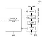
- FIG. 4is a block diagram of a power transmitter including a coil assembly according to a first or second embodiment.
- the power transmitter 4010may include two main units, a power conversion unit 4020 and a communication / control unit 4030.
- the power conversion unit 4020may communicate with the communication / control unit 4030.
- the power conversion unit 4020may be in charge of / include the analog part of the power transmitter design including the coil assembly according to the first or second embodiment.
- the power conversion unit 4020may include an inverter, a coil selection block, and / or a current sense unit.
- a direct current (DC) input of the power conversion unit 4020may be received, which may be converted into an AC waveform for driving a resonant circuit including a series capacitor and a selected coil.
- the coil selectedmay mean one coil appropriately selected according to the position of the power receiver among the coils arranged in a line according to the first or second embodiment.
- the power conversion unit 4020(or coil selection block) may select one of the coils included in the coil assembly suitable for charging the power receiver in consideration of the position of the power receiver placed on the coil assembly. have.
- the coil selectionis performed by the power transmitter 4010 (or power conversion unit 4020 / coil selection block) to communicate with the power receiver using at least one coil (or all coils in sequence) included in the coil assembly. It can be performed / progressed in real time by / trying. That is, the power transmitter 4010 (or the power conversion unit 4020 / coil selection block) may acquire the location of the power receiver by communicating with the power receiver using at least one coil, One coil of the corresponding position can be selected.
- the power transmitter 4010may attempt to communicate with the power receiver using the first to third coils included in the coil assembly, among which It may be assumed that the communication with the attempted power receiver using one coil is successful.
- the power transmitter 4010(or power conversion unit 4020) may infer / predict that the current power receiver lies on (or closest to) the first coil, It can be selected as a coil to drive for charging the power receiver.
- the power transmitter 4010may include a separate sensor (for example, a proximity sensor or an infrared sensor) for acquiring the position of the power receiver.
- the power transmitter 4010may acquire the position of the power receiver by using the corresponding sensor, and select a coil having a position suitable for charging the power receiver as the driving coil.
- the power conversion unit 4020(or current sense unit) may continuously monitor the current flowing in the selected coil.
- the communication / control unit 4030may be in charge of / include the digital logic part of the power transmitter design incorporating the coil assembly according to the first or second embodiment.
- the communication / control unit 4030can receive and decode a message sent from a power receiver, configure a coil selection block for connection with an appropriate coil, and execute a power control algorithm / protocol associated with it. have.
- the communication / control unit 4030may control / drive the frequency of the AC waveform for controlling power transmission.
- the communication / control unit 4030may interface with other subsystems of the base station (eg, for purposes of a user interface).
- the block diagramillustrates and describes the power conversion unit 4020 and the communication / control unit 4030
- the present inventionis not limited thereto, and at least one of the functions performed by the power conversion unit 4020 may be used for communication / control. At least one of the functions performed by the unit 4030 or performed by the communication / control unit 4030 may be performed by the power conversion unit 4020.
- the power conversion unit 4020 and the communication / control unit 4030may be configured as a separate chip or a single chip in hardware.
- the block diagram of the power transmitter 4010 operating in the single coil driving methodhas been described above.
- a structure and a block diagram of a coil assembly included in a power transmitter operating in a multi-coil driving methodwill be described.
- the third embodiment of the coil assembly included in the power transmittermay have four coils arranged in first and second directions.
- two coilsmay be arranged in the first and second directions, respectively (2X2).
- the first and second directionsmay represent various directions that cross each other.
- the first directionmay be an up ⁇ down direction (or down ⁇ up direction)
- the second directionmay be left ⁇ right direction (or right ⁇ left direction).
- the four coilsmay be arranged such that at least some of them overlap each other in the first and second directions.
- each coil included in the coil assemblymay be about 110 mm ⁇ 70 mm (w / Ferrite), and the maximum charge area that may be generated by the coil assembly may be about 46 mm ⁇ 46 mm (w / Ferrite).
- the coil assembly of the third embodimentmay operate in a multi-coil drive manner.
- the multi-coil driving methodmay refer to a method of simultaneously driving a plurality of coils at one time (that is, applying current to the plurality of coils at once / simultaneously).
- the fourth embodiment of the coil assembly included in the power transmittermay include six coils arranged in first and second directions. More specifically, two coils in the first direction and three coils in the second direction may be configured (3 ⁇ 2).
- the first and second directionsmay represent various directions that cross each other.
- the first directionmay be an up ⁇ down direction (or down ⁇ up direction), and the second direction may be left ⁇ right direction (or right ⁇ left direction).
- the six coilsmay be arranged such that at least some of them overlap each other in the first and second directions.
- each coil included in the coil assemblymay be about 110 mm ⁇ 70 mm (w / Ferrite), and the maximum charge area that may be generated by the coil assembly may be about 60 mm ⁇ 46 mm (w / Ferrite).
- the coil assembly of the fourth embodimentmay also operate in a multi-coil drive method as in the third embodiment.
- the configuration unit of the power transmitter including the coil assembly operating in the multi-coil driving methodwill be described as in the third and fourth embodiments.
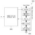
- FIG. 5illustrates a block diagram of a power transmitter including a coil assembly according to a third or fourth embodiment. Since the power transmitter including the coil assembly according to the third or fourth embodiment transmits the power by using an “array” of a plurality of partially overlapped coils (that is, by applying a multi-coil driving scheme), the power Ensure positional freedom of receiver.
- the power transmitter 5010may largely include two main units, a power conversion unit 5020 and a communication / control unit 5030.
- the power conversion unit 5020may communicate with the communication / control unit 5030.
- the power conversion unit 5020may be in charge of / include an analog part of the design of the power transmitter 5010 including the coil assembly according to the third or fourth embodiment.
- the power conversion unit 5020may include an inverter, an impedance matching network, a sensing circuit, and / or a multiplexer.
- a DC (direct current) input of the power conversion unit 5020may be received, and may be converted into an AC waveform for driving a resonant circuit including a selected / connected coil.
- the selected / connected coilmay mean a coil arrangement (or a plurality of coils) appropriately selected according to the position of the power receiver among the coils arranged according to the third or fourth embodiment.
- the selection of coilsmay be performed / produced in real time by the power transmitter 5010 (or power conversion unit 5020 / multiplexer) performing / attempting to communicate with the power receiver using at least one coil included in the coil assembly. Can be. That is, the power transmitter 5010 (or the power conversion unit 5020 / multiplexer) may acquire the location of the power receiver by communicating with the power receiver using at least one coil, One coil of the corresponding position can be selected.
- the power transmitter 5010may attempt to communicate with the power receiver using the first through sixth coils included in the coil assembly, of which It may be assumed that the communication with the attempted power receiver using one coil is successful.
- the power transmitter 5010(or power conversion unit 5020) may infer / predict that the current power receiver lies on (or closest to) the first coil, It can be selected as a coil to drive for charging the power receiver.
- the power transmitter 5010may include a separate sensor (eg, proximity sensor, infrared sensor, etc.) for acquiring the position of the power receiver. It may be.
- the power transmitter 5010may acquire the position of the power receiver by using the corresponding sensor, and may select a coil having a position suitable for charging the power receiver as the driving coil.
- the power conversion unit 5020may form a resonant circuit for the selected / connected coil portions.
- the power conversion unit 5020(or sensing circuit) may continuously monitor the current / voltage of the selected / connected coils.
- the power conversion unit 5020may be coupled with an appropriate coil and / or with an inappropriate coil that may transmit power to the power receiver based on the location of the power receiver.
- a suitable coil capable of transmitting power to the power receivermay refer to at least one coil capable of forming a charging region at the location of the power receiver.
- the communication / control unit 5030may be in charge of / include the digital logic part of the design of the power transmitter 5010 with the coil assembly according to the third or fourth embodiment.
- the communication / control unit 5030can receive and decode a message sent from a power receiver, configure a multiplexer to connect with the appropriate coil arrangement, and execute the power control algorithm / protocol associated with it. Can be.
- the communication / control unit 5030may drive an inverter for controlling the amount of power to be provided to the power receiver.
- the communication / control unit 5030may interface with other subsystems of the base station (eg, for user interface purposes).
- the block diagramillustrates and describes the power conversion unit 5020 and the communication / control unit 5030
- the present inventionis not limited thereto, and at least one of the functions performed by the power conversion unit 5020 may be used for communication / control.
- the at least one of the functions performed by the unit 5030 or the communication / control unit 5030may be performed by the power conversion unit 5020.
- the power conversion unit 5020 and the communication / control unit 5030may be configured as separate chips in hardware or as one chip.
- the numerical values shown in units of coil size and mmmay have an error range of up to ⁇ 5 mm.
- the fourth embodimenthas the best performance in terms of charging area and efficiency.
- an effect of reducing the dead zone (area)occurs as compared to the single coil method, which will be described later in detail with reference to FIG. 6. .
- an area in which the receiving coil of the power receiver is induced with a voltage greater than or equal to a threshold voltagemay be referred to as an active zone (area), and the voltage is induced beyond the threshold voltage.
- An area that is not availableie, an area where the power receiver cannot be charged
- a dead zonearea
- FIG. 6 (a)shows an example of applying a single coil driving method to a coil assembly
- FIG. 6 (b)shows an example of applying a multi coil driving method.
- FIG. 6 (a) and 6 (b)assume that the power receiver is centered in the coil assembly of the power transmitter.
- the power transmittermay apply a single coil driving method of driving only one coil at a time among transmission coils constituting the transmission coil assembly (or transmission coil array). Therefore, the power transmitter of this embodiment can drive only one of the coils, even if both of the transmitting coils are capable of transmitting power to the power receiver (or receiving coil / secondary coil).
- the power transmittermay apply a multi-coil driving method of simultaneously driving a plurality of coils among the transmission coils constituting the transmission coil assembly (or the transmission coil array). Therefore, the power transmitter of the present embodiment can drive both transmission coils capable of transmitting power to the power receiver.
- the dead zone 6010is not generated.
- the insides of the two transmitting coilsare arranged to meet or overlap with each other (or when the through-holes of each coil and the through-holes of neighboring coils in the first or second direction are overlapped and arranged in a plane) Since the distance of the magnetic field passing through the center of each coil is closer to each other, dead zone can be further minimized. As a result, the chargeable area for the power receiver is increased compared to the single coil driving method, and the charging efficiency is also increased.
- a fourth embodimentin which a plurality of coils are arranged to overlap each other in the first and second directions as a transmission coil assembly structure is proposed.
- FIG. 7illustrates a coil assembly structure and an equivalent circuit according to an embodiment of the present invention.
- the coil assembly of the power transmittermay include six coils as described above, in which two coils are arranged in a first direction and three coils are arranged in a second direction. It can be configured (3X2).
- the first and second directionsmay represent various directions that cross each other.
- the first directionmay be an up ⁇ down direction (or down ⁇ up direction), and the second direction may be left ⁇ right direction (or right ⁇ left direction).
- the six coilsmay be arranged such that at least some of them overlap each other in the first and second directions, and in particular, the neighboring coils may be arranged to meet or overlap each other.
- the coil assembly of the power transmittermay operate in a multi-drive scheme to widen the charging region and minimize the dead zone.
- the power transmittermay basically determine the multi-driven coils based on the position of the power receiver. That is, the power transmitter may determine coils of a position capable of transmitting power to the power receiver or coils capable of forming a magnetic field at the position of the power receiver as the multi-driven coil. The power transmitter may control the coils to be multi-dried by controlling the current to flow in the same rotation direction.
- the power transmittermay selectively multi-drive “neighboring / overlapping coils in the first and second directions” among the coils at positions where power transmission is possible to the power receiver in order to minimize dead zones. This is because, when driving the coils located in the diagonal direction at the same time, the magnetic field passing through the center of each coil and the magnetic field passing through the center of the other coils are separated in the first direction and thus the dead zone cannot be minimized.
- the combination of the multi-driven coils in the case of the coil assembly of FIG. 7 (a)is (1, 2), (2, 3), (1, There may be seven such as A), (2, B), (3, C), (A, B) and (B, C).
- a combination of coils that cannot be driven at the same timemay have (A, 2, C) and (1, B, 3).
- Equation 1the number C_operating of the multi-driven coil combinations for the coil assembly including 2n coils.
- an equivalent circuit for the coil assembly of FIG. 7 (a) that drives up to two coils in a multi-drive, multi-drives adjacent / overlapping coils in the first and second directions, and does not multi-coil the coils located in a diagonal direction.May be represented as shown in FIG.
- the present inventionhas been described above with respect to an embodiment of multi-driving up to two coils, the present invention is not limited thereto, and multi-driving may be performed regardless of the number of coils located adjacently / overlapping in the first and second directions. However, even in this case, current must flow in the same direction of rotation to the coils that are multi-driven at the same time.
- FIG. 8 (a)is a plan view of a coil assembly consisting of two coils
- FIG. 8 (b)is a side view of the coil assembly viewed from the A direction
- FIG. 8 (c)is a side view of the coil assembly viewed from the B direction.
- the coils constituting the coil assemblyshould have the same inductance value on average.
- a shield and / or a spacermay be provided together with the coils in the coil assembly.
- the coilsmay be sequentially stacked on the shield to constitute a coil assembly.
- at least a part of each coilmay be stacked to overlap each other (see FIG. 8A).
- the coil assemblyis composed of multiple coils of two, another coil stacked on a specific coil is floating from the shielding material, so that a spacer is inserted between the two coils to maintain a constant gap between the two coils.
- the spacer to be insertedmay correspond to a nonmagnetic material.
- FIG. 9 (a)is a plan view of a coil assembly consisting of four coils
- FIG. 9 (b)is a side view of the coil assembly viewed from the A direction
- FIG. 9 (c)is a side view of the coil assembly viewed from the B direction.
- the coilsmay be sequentially stacked on the shield to constitute a coil assembly.
- a two-layer shieldmay be used in addition to the one-layer shield stacked on the bottommost layer.
- the two-layer shielding materialmay be laminated on the one-layer shielding material to perform a function of supporting another coil laminated on the coils stacked on the one-layer shielding material.
- the inductance of the coil laminated on the two-layer shielding materialcan be made the same / similar size as the coil laminated on the one-layer shielding material. Furthermore, in order to maintain the same / similar inductance value between the coils, the number of coils and the coil size of the stacked coils may be different from each other.
- a plurality of shieldsmay be used to support the coils stacked on the bottom layer even when using a coil assembly using six coils, and an inductance value between the coils stacked on each shield is used. This may remain the same / similar.
- FIG. 10is a graph illustrating a charging region test result of a power transmitter to which a coil assembly structure according to an exemplary embodiment of the present invention is applied. More specifically, Figure 10 (a) is a coil assembly structure used in the experiment, Figure 10 (b) is a graph showing the test results of the charging region of the coil assembly of Figure 10 (a).
- the maximum spacing between the insides of the coils arranged in the first direction of the coil assemblymay be set to about 50 mm, and the maximum spacing between the insides of the coils arranged in the second direction may be set to about 70 mm.
- the chargeable region (ie, the active zone) of the coil assembly of FIG. 10 (a)is very wide, about 60 mm 60 46 mm, as shown in FIG. 10 (b), and it can be confirmed that there is almost no dead zone. .
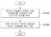
- FIG. 11is a flowchart illustrating a power transmission method of a power transmitter according to an embodiment of the present invention.
- 1 to 10may be identically / similarly applied to the flowchart, and redundant descriptions thereof will be omitted.
- the power transmittermay acquire the position of the power receiver using a coil assembly including a plurality of coils (S11010).
- the power transmittermay attempt to communicate with the power receiver using the first to sixth coils included in the coil assembly, and it is assumed that the communication with the power receiver attempted using the first coil is successful. can do.
- the power transmittermay infer / predict that the current power receiver lies on (or closest to) the first coil and select the first coil as the coil to drive for charging the power receiver. have.
- the power transmittermay include a separate sensor for acquiring the position of the power receiver to sense the position of the power receiver.
- the power transmittermay charge the power receiver by multi-driving the coils at positions corresponding to the positions of the power receiver (S11020).
- the multi-driving operationcorresponds to the position of the power receiver among the plurality of coils, and simultaneously applies AC to neighboring coil pairs in the first or second direction, so that AC flows in the same rotational direction in the coil pair. It may correspond to the step of applying.
- the coil structure of the wireless power transceiver to which the multi-coil driving method and the multi-coil driving method are appliedhas been described above.
- a bidirectional communication protocol method of a wireless power transmission / reception period for more wirelessly transmitting and receiving wireless powerwill be described.
- FIG. 12is a flowchart illustrating a charging control process of a wireless power transmission / reception period for wireless power transmission according to an embodiment of the present invention.
- the wireless power transmitter Txmay be in a ready / standby state in which power is not transmitted to the wireless power receiver Rx (S12010).
- the wireless power transmitter Txmay recognize the wireless power receiver Rx (S12020).
- the wireless power transmitter Txmay recognize the wireless power receiver Rx according to various embodiments.
- the wireless power transmitter Txmay perform communication with the power receiver or acquire a location of the power receiver.
- An additional sensoreg, proximity sensor, infrared sensor, etc. may be used to recognize the power receiver.
- the wireless power transmitter Txperforms charging setting for transmitting and receiving power with the wireless power receiver Rx (S12030) and adjusts a power level to be transmitted to the wireless power receiver Rx according to the charging setting (S12040).
- the wireless power receiver Rxmay transmit maximum power information, which is information about a (maximum) power level that it intends to receive (or receive), for the charging setting of the wireless power transmitter Tx. It can transmit in (Tx).
- the wireless power transmitter Txmay adjust the power level to be transmitted to the wireless power receiver Rx at the same time as the charging setting to the wireless power receiver Rx is performed based on the received maximum power information.
- the wireless power transmitter Txmay charge the wireless power receiver Rx by transmitting power to the wireless power receiver Rx (S12050).
- Steps S12040 and S12050may be defined as a voltage control loop, and when the power receiver receives a change in the (maximum) power level to be received (or receivable) as the power is received, the power receiver returns to step S12040 to the power transmitter. You may request to adjust the transmit power.
- the wireless power receiver (Rx)requests the wireless power transmitter (Tx) to adjust the power level by sending information about the new (maximum) power level it is trying to receive (or can receive) to the wireless power transmitter (Tx). Can be.
- the wireless power transmitter Txmay adjust the power level transmitted to the wireless power receiver Rx by performing step S12050 according to the request of the wireless power receiver Rx.
- the wireless power receiver Rxmay request the wireless power transmitter Tx to terminate the charging (S12060).
- the wireless power receiver Rxis predominantly adjusted to control the transmission power level. That is, the wireless power receiver Rx directly requests the wireless power transmitter Tx to receive the power level it wants to receive, and the wireless power transmitter Tx adjusts the transmission power level according to the request of the wireless power receiver Rx. Done.
- the wireless power transmitter (Tx)starts charging in a medium power transmission mode (a mode capable of charging up to 15W), but stops charging itself when it is overheated and waits. After returning to, the device was set to a low power mode (a mode capable of charging up to 5W) in the charge setting step, and charging of the wireless power receiver Rx was resumed. If the temperature of the wireless power transmitter Tx falls below a preset temperature, the wireless power transmitter Tx returns to the standby stage and then resets to the intermediate power transfer mode in the charging setting stage, thereby resetting the wireless power receiver Rx. The charging of was resumed.
- a medium power transmission modea mode capable of charging up to 15W
- a low power modea mode capable of charging up to 5W
- the present specificationproposes a bidirectional communication mechanism between the wireless power transmitter Tx and the receiver so that the wireless power transmitter Tx can also adjust the transmission power level.
- FIG. 13is a flowchart illustrating a charging control process between wireless power transceivers Tx and Rx for wireless power transmission according to an embodiment of the present invention.
- steps S12010 to S12060 described above with reference to FIG. 12may be identically / similarly to steps S13010 to 1350 and S13070.
- steps S13010 to 1350 and S13070may be identically / similarly to steps S13010 to 1350 and S13070.
- the present flow chartwill be described focusing on the difference from the embodiment of Figure 12 and overlapping description is omitted.
- steps S13040 to S13060may be defined as a voltage control loop.
- the wireless power transmitter Txmay transmit a request to adjust the (maximum) power level to the wireless power receiver Rx (S13060).
- This requestmay include maximum power level information regarding the new (maximum) power level required by the wireless power transmitter (Tx).
- the wireless power transmitter Txmay correspond to a case where a current temperature detected by the wireless power transmitter Tx exceeds a preset temperature or a foreign substance is detected. .
- the wireless power transmitter Txmay be provided with a hardware configuration such as a temperature sensor that can measure the current temperature and / or a foreign matter detection module that can detect a foreign matter.
- the wireless power transmitter (Tx)may send a request to the wireless power receiver (Rx) to reduce the (maximum) power level, which may be adjusted for a new (maximum) power level that is set below the current power level.
- Power level informationmay be included.
- the wireless power transmitter Txwhen it is determined that the wireless power transmitter Tx needs to adjust the transmission power level, when the wireless power transmitter Tx detects that the temperature exceeding the preset temperature falls below the preset temperature or is detected, This may also be the case when foreign matter is removed.
- the wireless power transmitter (Tx)may send a request to the wireless power receiver (Rx) to increase the (maximum) power level, which includes a request for a new (maximum) power level set greater than the current power level.
- the adjusted power level informationmay be included.
- the wireless power receiver Rx receiving the (maximum) power level adjustment request from the wireless power transmitter Txreturns to step S13040 and adjusts the (maximum) power level based on the request. May be requested. More specifically, the wireless power receiver Rx determines the (maximum) power level within the new (maximum) power level indicated by the adjusted power level information included in the request, and powers to the determined (maximum) power level. Adjustment can be requested to the wireless power transmitter (Tx).
- the wireless power transmitter Txmay charge the wireless power receiver Rx by adjusting the power to a (maximum) power level newly requested from the wireless power receiver Rx (S13060).
- the wireless power transceivers Tx and Rxhave an effect that the power can be transmitted more stably and efficiently by appropriately negotiating / adjusting the level of power to be transmitted according to the power control loop according to the transmission environment and situation. In addition, according to the present embodiment, it does not occur in a situation where the power transmission is unilaterally stopped by the wireless power transmitter Tx, so that the charging time is reduced.
- FIG. 14is a diagram illustrating a method for controlling overheating in a multi-coil according to an embodiment of the present invention.
- the wireless power transmitter Txincluding the coil assembly composed of multiple coils, as shown in FIG. 14, the alignment between the coils of the wireless power transmitter Tx and the coils of the wireless power receiver Rx do not match. Under poor coupling conditions, the charging efficiency is lowered and heat generation is likely. To prevent this, the wireless power transmitter Tx may selectively drive at least one coil during power transmission. In addition, the wireless power transmitter Tx may set the wireless power transmitter Tx located at an outer portion of which transmission / charging efficiency is low to request a power level lower than a predetermined level.
- the wireless power transmitter Txdetects a first position (a good coupling position (for example, a central portion of the coil assembly)) as the wireless power receiver Rx position
- the plurality of coilsmay be multi- / simultaneously driven to transmit high power (up to 15W) to the corresponding wireless power receiver Rx.
- a second positiona poor coupling position (for example, an outer portion of the coil assembly)
- Low power5W maximum
- RxLow power
- the wireless power transmitter Txwirelessly transmits information about the appropriate power level according to the position of each wireless power receiver Rx so that the wireless power receiver Rx can request / set the appropriate power level according to its own position. It can be transmitted to the power receiver (Rx).
- the wireless power transmitter Txdetects the first position (the position where the coupling is good (for example, the central portion of the coil assembly)) as the wireless power receiver Rx position, the wireless power transmitter Tx. ) May indicate that the wireless power transmitter Tx is capable of up to 15 W as the (maximum) power level currently settable. Accordingly, the wireless power receiver may set a receivable (maximum) power level up to 15W in the charging setting step.
- the wireless power transmitter Txwhen the wireless power transmitter Tx detects a second position (a poor coupling position (for example, an outer portion of the coil assembly)) as the wireless power receiver Rx position, the wireless power transmitter Tx. May instruct the wireless power transmitter Tx to be up to 5W as the currently configurable (maximum) power level. Accordingly, the wireless power receiver may set a receivable (maximum) power level up to 5W in the charge setting step.
- FIG. 15is a flowchart illustrating a power transmission method of a wireless power transmitter according to an embodiment of the present invention. Descriptions of the above-described embodiments with respect to this flowchart may be applied in the same or similar manner, and redundant descriptions are omitted.
- the wireless power transmittermay recognize the wireless power receiver (S1510).
- the wireless power transmittermay include various hardware configurations for recognizing the wireless power receiver, and a detailed description thereof is as described above.
- the wireless power transmittermay receive first maximum power level information regarding the first maximum power level that can be received by the wireless power receiver from the wireless power receiver (S1520).
- the wireless power transmitterdetermines a level (less than the first maximum power level) of power to be transmitted to the wireless power receiver based on the first maximum power level information received from the wireless power receiver, and wirelessly transmits the determined level of power.
- the transmissionmay be transmitted to the power receiver (S1530).
- the wireless power transmittermay detect the current temperature (S1540).
- the wireless power transmittermay have various hardware configurations (eg, temperature sensors, etc.) capable of detecting the current temperature.
- the wireless power transmittermay transmit adjusted power level information indicating a power level greater than or less than the first maximum power level to the wireless power receiver based on the detected current temperature (S1550).
- the adjusted power level informationmay indicate a power level smaller than the first maximum power level when the detected current temperature is higher than the preset temperature.
- the adjusted power level informationmay indicate a power level higher than the first maximum power level when the detected current temperature is lower than the preset temperature.
- the wireless power transmittermay receive second maximum power level information about the second maximum power level adjusted based on the adjusted power level information (S1560).
- the wireless power transmittermay transmit power to the wireless power receiver at a power level determined based on the received second maximum power level information (S1570).
- the wireless power transmitterwhen the wireless power transmitter includes a coil assembly composed of a plurality of coils, the wireless power transmitter may acquire the position of the wireless power receiver using the coil assembly. In this case, the wireless power transmitter may transmit information about the maximum power level that the wireless power transmitter can supply to the wireless power receiver based on the acquired position of the wireless power receiver. The maximum power level when the first position is obtained as the position of the wireless power receiver may be set greater than the maximum power level when the second position is obtained as the position of the wireless power receiver. In this case, the first position may correspond to the center of the coil assembly of the wireless power transmitter, and the second position may correspond to an outer portion of the coil assembly of the wireless power transmitter.
- the wireless power transmittermay multi-drive at least some of the plurality of coils included in the coil assembly.
- the multi-drivingmeans driving a plurality of coils simultaneously by simultaneously applying current / voltage to at least two or more coils among the coils included in the coil assembly.
- the wireless power transmittermay selectively drive one coil having a position corresponding to the second position among the plurality of coils included in the coil assembly.
- the wireless power transceiveris not limited to the configuration and method of the embodiments described as described above, the above-described embodiments may be selectively combined with all or some of the embodiments so that various modifications can be made It may be configured.
- the present inventioncan be applied to various wireless charging technologies.
Landscapes
- Engineering & Computer Science (AREA)
- Power Engineering (AREA)
- Computer Networks & Wireless Communication (AREA)
- Signal Processing (AREA)
- Charge And Discharge Circuits For Batteries Or The Like (AREA)
Abstract
Description
Translated fromKorean본 발명은 무선 전력 송신기 및 수신기의 구조 및 제어 방법을 그 대상으로 한다.The present invention is directed to the structure and control method of the wireless power transmitter and receiver.
무접점(Contactless) 무선 충전 방식은 기존의 유선을 통해 에너지를 전송하여 전자기기의 전원으로 사용하는 방식에서, 선을 제거하고 전자기적으로 에너지를 전달하는 에너지 전달 방식이다. 무접점 무선 전송 방식에는 전자기 유도 방식 및 공진 방식이 존재한다. 전자기 유도 방식은 전력 송신부에서 전력 송신 코일(1차 코일)을 통해 자기장을 발생시키고, 전류가 유도될 수 있는 위치에 수신 코일(2차 코일)을 위치시킴으로써 전력을 전달하는 방식이다. 공진 방식은, 송신 코일 및 수신 코일 간의 공명 현상을 이용하여 에너지를 전송한다. 다만, 1차 코일의 공진 주파수와 2차 코일의 공진 주파수를 동일하게 시스템을 구성함으로써 코일 간의 공진 모드 에너지 결합을 사용한다.Contactless wireless charging is an energy transfer method that removes lines and transfers energy electromagnetically in a method of transmitting energy through a conventional wire and using it as a power source of an electronic device. In the non-contact wireless transmission method, electromagnetic induction method and resonance method exist. The electromagnetic induction method is a method of generating a magnetic field through the power transmission coil (primary coil) in the power transmission unit and transferring power by placing a receiving coil (secondary coil) at a position where a current can be induced. In the resonance method, energy is transmitted by using a resonance phenomenon between a transmitting coil and a receiving coil. However, the resonance mode energy coupling between coils is used by constructing a system in which the resonance frequency of the primary coil and the resonance frequency of the secondary coil are the same.
본 발명의 목적은 충전 영역이 넓어 충전 효율/성능이 좋은 새로운 무선 전력 송신기의 코일 어셈블리 구조를 제안함을 그 목적으로 한다.An object of the present invention is to propose a coil assembly structure of a new wireless power transmitter having a wide charging area and good charging efficiency / performance.
또한, 본 발명의 목적은 무선 전력 송신기의 충전 환경/상황에 따라 유연하게 전송 전력 레벨을 조절할 수 있는 무선 전력 송수신간 양방향 통신 프로토콜을 제안함을 그 목적으로 한다.In addition, an object of the present invention is to propose a bidirectional communication protocol between wireless power transmission and reception that can flexibly adjust the transmission power level according to the charging environment / situation of the wireless power transmitter.
본 발명의 일 실시예에 따르면, 무선 전력 수신기로 전력을 전송하는 무선 전력 송신기에 있어서, 복수의 코일들을 포함하는, 코일 어셈블리; 입력된 DC(direct current)를 상기 코일 어셈블리를 구동하기 위한 AC(alternating current)로 전환하는, 전력 변환 유닛; 및 상기 전력 수신기와 통신을 수행하고, 상기 코일 어셈블리를 이용하여 상기 전력 수신기로 전송할 전력량을 제어하는, 통신/컨트롤 유닛; 을 포함하되, 상기 복수의 코일들은 제1 및 제2 방향으로 배열되되, 상기 복수의 코일들 각각은, 중심에 관통홀이 형성된 실질적인 사각형 모양의 프레임 구조를 가지며, 적어도 일부 영역이 상기 제1 및 제2 방향으로 이웃하는 코일과 평면상에서 중첩되도록 배열될 수 있다.According to one embodiment of the invention, a wireless power transmitter for transmitting power to a wireless power receiver, comprising: a coil assembly comprising a plurality of coils; A power conversion unit for converting an input direct current (DC) into an alternating current (AC) for driving the coil assembly; A communication / control unit communicating with the power receiver and controlling the amount of power to be transmitted to the power receiver using the coil assembly; Including, The plurality of coils are arranged in the first and second directions, each of the plurality of coils, has a substantially rectangular frame structure with a through hole formed in the center, at least a portion of the first and second It may be arranged to overlap in plane with the coil adjacent to the second direction.
또한, 상기 제1 및 제2 방향은 실질적으로 서로 직교하는 방향일 수 있다.In addition, the first and second directions may be substantially perpendicular to each other.
또한, 상기 제1 방향은 수직 방향 또는 상하 방향, 상기 제2 방향은 수평 방향 또는 좌우 방향에 각각 해당할 수 있다.The first direction may correspond to a vertical direction or an up and down direction, and the second direction may correspond to a horizontal direction or a left and right direction, respectively.
또한, 상기 복수의 코일들은, 평면상에서 각 코일의 관통홀과 상기 제1 또는 제2 방향으로 이웃하는 코일의 관통홀이 인접하도록 중첩되어 배열될 수 있다.In addition, the plurality of coils may be arranged in such a manner that the through-holes of each coil and the through-holes of neighboring coils in the first or second direction are adjacent to each other on a plane.
또한, 상기 복수의 코일들은 6개의 코일들로 구성될 수 있다.In addition, the plurality of coils may be composed of six coils.
또한, 상기 복수의 코일들은 실질적으로 동일한 인덕턴스 값을 갖도록 서로 다른 감은 수 및 크기를 가질 수 있다.In addition, the plurality of coils may have different winding numbers and sizes so as to have substantially the same inductance value.
또한, 상기 전력 변환 유닛은, 상기 코일 어셈블리를 이용하여 상기 전력 수신기의 위치를 획득하고, 상기 전력 수신기의 위치와 대응되는 위치의 복수의 코일들을 선택하고, 상기 선택한 복수의 코일들로 상기 AC를 인가할 수 있다.The power conversion unit may be further configured to acquire a position of the power receiver using the coil assembly, select a plurality of coils at positions corresponding to the position of the power receiver, and convert the AC into the selected plurality of coils. Can be authorized.
또한, 상기 전력 변환 유닛에 의해 선택되는 코일들은 상기 제1 또는 제2 방향으로 이웃하는 코일 쌍에 해당할 수 있다.Further, the coils selected by the power conversion unit may correspond to coil pairs neighboring in the first or second direction.
또한, 상기 전력 변환 유닛은, 상기 코일 쌍으로 상기 AC를 인가하되, 상기 AC가 상기 선택한 코일 쌍에서 동일한 회전 방향으로 흐르도록 상기 AC를 인가할 수 있다.In addition, the power conversion unit may apply the AC to the coil pair, but may apply the AC so that the AC flows in the same rotational direction in the selected coil pair.
또한, 본 발명의 다른 실시예에 따른 무선 전력 수신기로 전력을 전송하는 무선 전력 송신기의 전력 송신 방법에 있어서, 복수의 코일들이 포함된 코일 어셈블리를 이용하여 상기 전력 수신기의 위치를 획득하는 단계; 및 상기 복수의 코일들 중 상기 전력 수신기의 위치와 대응되는 위치의 코일들을 멀티 구동하는 단계; 를 포함하되, 상기 멀티 구동하는 단계는, 상기 복수의 코일들 중 제1 또는 제2 방향으로 이웃하는 코일 쌍에 동시에 AC를 인가하되, 상기 AC가 상기 코일 쌍에서 동일한 회전 방향으로 흐르도록 인가할 수 있다.In addition, the power transmission method of the wireless power transmitter for transmitting power to the wireless power receiver according to another embodiment of the present invention, the method comprising: obtaining a position of the power receiver using a coil assembly including a plurality of coils; And multi-coiling coils at positions corresponding to positions of the power receiver among the plurality of coils; Including the multi-drive step, the AC is applied to the adjacent pair of coils in the first or second direction of the plurality of coils at the same time, the AC is applied to flow in the same rotation direction in the coil pair Can be.
또한, 상기 복수의 코일들은 제1 및 제2 방향으로 배열되되, 상기 복수의 코일들 각각은, 중심에 관통홀이 형성된 실질적인 사각형 모양의 프레임 구조를 가지며, 적어도 일부 영역이 상기 제1 및 제2 방향으로 이웃하는 코일과 평면상에서 중첩되도록 배열될 수 있다.In addition, the plurality of coils are arranged in the first and second directions, each of the plurality of coils has a substantially rectangular frame structure with a through hole formed in the center, at least a portion of the first and second It may be arranged to overlap in the plane with the neighboring coil in the direction.
또한, 상기 제1 및 제2 방향은 실질적으로 서로 직교하는 방향일 수 있다.In addition, the first and second directions may be substantially perpendicular to each other.
또한, 상기 제1 방향은 수직 방향 또는 상하 방향, 상기 제2 방향은 수평 방향 또는 좌우 방향에 각각 해당할 수 있다.The first direction may correspond to a vertical direction or an up and down direction, and the second direction may correspond to a horizontal direction or a left and right direction, respectively.
또한, 본 발명의 다른 실시예에 따른 무선 전력 수신기로 전력을 전송하는 무선 전력 송신기의 전력 송신 방법에 있어서, 상기 무선 전력 수신기를 인식하는 단계; 상기 무선 전력 수신기로부터 상기 무선 전력 수신기가 수신 가능한 제1 최대 전력 레벨에 관한 제1 최대 전력 레벨 정보를 수신하는 단계; 상기 제1 최대 전력 레벨 정보에 기초하여 결정된 전력 레벨로 상기 전력을 상기 무선 전력 수신기로 전송하는 단계; 현재 온도를 검출하는 단계; 상기 검출한 현재 온도에 기초하여, 상기 제1 최대 전력 레벨보다 크거나 작은 전력 레벨을 지시하는 조절 전력 레벨 정보를 상기 무선 전력 수신기로 전송하는 단계; 상기 조절 전력 레벨 정보에 기초하여 조절된 제2 최대 전력 레벨에 관한 제2 최대 전력 레벨 정보를 상기 무선 전력 수신기로부터 수신하는 단계; 및 상기 제2 최대 전력 레벨 정보에 기초하여 결정된 전력 레벨로 상기 전력을 상기 무선 전력 수신기로 전송하는 단계; 를 포함할 수 있다.Also, a power transmission method of a wireless power transmitter for transmitting power to a wireless power receiver according to another embodiment of the present invention, the method comprising: recognizing the wireless power receiver; Receiving first maximum power level information about a first maximum power level that the wireless power receiver can receive from the wireless power receiver; Transmitting the power to the wireless power receiver at a power level determined based on the first maximum power level information; Detecting a current temperature; Transmitting, to the wireless power receiver, adjusted power level information indicating a power level greater than or less than the first maximum power level based on the detected current temperature; Receiving, from the wireless power receiver, second maximum power level information regarding a second maximum power level adjusted based on the adjusted power level information; And transmitting the power to the wireless power receiver at a power level determined based on the second maximum power level information. It may include.
또한, 상기 조절 전력 레벨 정보는, 상기 검출한 현재 온도가 기설정된 온도보다 높은 경우, 상기 제1 최대 전력 레벨보다 작은 전력 레벨을 지시하며, 상기 검출한 현재 온도가 상기 기설정된 온도보다 낮은 경우, 상기 제1 최대 전력 레벨보다 높은 전력 레벨을 지시할 수 있다.The adjusted power level information indicates a power level smaller than the first maximum power level when the detected current temperature is higher than a preset temperature, and when the detected current temperature is lower than the preset temperature, It may indicate a power level higher than the first maximum power level.
또한, 상기 무선 전력 송신기의 전력 송신 방법은 상기 무선 전력 송신기가 복수의 코일들로 구성된 코일 어셈블리를 포함하는 경우, 상기 코일 어셈블리를 이용하여 상기 무선 전력 수신기의 위치를 획득하는 단계; 및 상기 획득한 무선 전력 수신기의 위치에 기초하여 상기 무선 전력 송신기가 공급 가능한 최대 전력 레벨에 관한 정보를 상기 무선 전력 수신기로 전송하는 단계; 를 더 포함할 수 있다.The wireless power transmitter may further include obtaining a position of the wireless power receiver using the coil assembly when the wireless power transmitter includes a coil assembly including a plurality of coils; And transmitting information about the maximum power level that can be supplied by the wireless power transmitter to the wireless power receiver based on the acquired position of the wireless power receiver. It may further include.
또한, 상기 무선 전력 수신기의 위치로서 제1 위치를 획득한 경우의 상기 최대 전력 레벨은 상기 무선 전력 수신기의 위치로서 제2 위치를 획득한 경우의 상기 최대 전력 레벨보다 크게 설정될 수 있다.The maximum power level when the first position is acquired as the position of the wireless power receiver may be set to be greater than the maximum power level when the second position is obtained as the position of the wireless power receiver.
또한, 상기 제1 위치는 상기 무선 전력 송신기의 상기 코일 어셈블리의 중심부에 해당하며, 상기 제2 위치는 상기 무선 전력 송신기의 상기 코일 어셈블리의 외곽부에 해당할 수 있다.The first position may correspond to a central portion of the coil assembly of the wireless power transmitter, and the second position may correspond to an outer portion of the coil assembly of the wireless power transmitter.
또한, 상기 무선 전력 송신기의 전력 송신 방법은 상기 무선 전력 수신기의 위치로서 상기 제1 위치를 획득한 경우, 상기 코일 어셈블리에 포함된 상기 복수의 코일들 중 적어도 일부를 멀티 구동하는 단계; 및 상기 무선 전력 수신기의 위치로서 상기 제2 위치를 획득한 경우, 상기 코일 어셈블리에 포함된 상기 복수의 코일들 중 상기 제2 위치와 대응하는 위치의 하나의 코일을 선택적으로 구동하는 단계; 를 더 포함할 수 있다.The method may further include: driving at least some of the plurality of coils included in the coil assembly when the first position is acquired as the position of the wireless power receiver; And selectively driving one coil having a position corresponding to the second position among the plurality of coils included in the coil assembly when the second position is obtained as the position of the wireless power receiver. It may further include.
또한, 본 발명의 다른 실시예에 따른 무선 전력 수신기로부터 전력을 수신하는 무선 전력 수신기의 전력 수신 방법에 있어서, 상기 무선 전력 송신기를 인식하는 단계; 상기 무선 전력 수신기가 수신 가능한 제1 최대 전력 레벨에 관한 제1 최대 전력 레벨 정보를 상기 무선 전력 송신기로 전송하는 단계; 상기 제1 최대 전력 레벨 이하의 전력 레벨로 상기 전력을 상기 무선 전력 송신기로부터 수신하는 단계; 상기 제1 최대 전력 레벨보다 크거나 작은 전력 레벨을 지시하는 조절 전력 레벨 정보를 상기 무선 전력 송신기로부터 수신하는 단계; 상기 조절 전력 레벨 정보에 기초하여 상기 제1 최대 전력 레벨을 조절하여 획득한 제2 최대 전력 레벨에 관한 제2 최대 전력 레벨 정보를 상기 무선 전력 송신기로부터 수신하는 단계; 및 상기 제2 최대 전력 레벨 이하의 전력 레벨로 상기 전력을 상기 무선 전력 송신기로부터 수신하는 단계; 를 포함할 수 있다.Further, a method for receiving power of a wireless power receiver for receiving power from a wireless power receiver according to another embodiment of the present invention, the method comprising: recognizing the wireless power transmitter; Transmitting, by the wireless power receiver, first maximum power level information about a first maximum power level receivable to the wireless power transmitter; Receiving the power from the wireless power transmitter at a power level below the first maximum power level; Receiving regulated power level information from the wireless power transmitter indicating power level greater than or less than the first maximum power level; Receiving, from the wireless power transmitter, second maximum power level information about a second maximum power level obtained by adjusting the first maximum power level based on the adjusted power level information; And receiving the power from the wireless power transmitter at a power level below the second maximum power level. It may include.
본 발명의 일 실시예에 따르면, 코일 어셈블리에 멀티 코일 구동 방식을 적용하므로, 충전 가능 영역은 넓되, 충전 불가능 영역은 최소화되어 충전 성능/효율이 높아진다는 효과를 갖는다.According to an embodiment of the present invention, since the multi-coil driving method is applied to the coil assembly, the chargeable area is wide, but the non-chargeable area is minimized to increase the charging performance / efficiency.
또한, 본 발명의 일 실시에에 따르면, 무선 전력 송수신기 사이의 양방향 통신을 통해 무선 전력 송수신기의 현재 충전 상황에 적합한 레벨로 전송 전력을 결정/조절/협상할 수 있어, 무선 전력 송신기가 보다 안전하게 무선 전력 수신기로 전력 송신이 가능하다는 효과를 갖는다.In addition, according to an embodiment of the present invention, through the two-way communication between the wireless power transceiver can determine / adjust / negotiate the transmission power to a level suitable for the current charging situation of the wireless power transceiver, the wireless power transmitter wirelessly It has the effect that power transmission is possible to the power receiver.
이외에, 본 발명의 실시예에 따른 다양한 효과는 이하에서 상세히 후술하기로 한다.In addition, various effects according to embodiments of the present invention will be described later in detail.
도 1은 무선 충전 시스템이 도입되는 다양한 전자 기기들의 실시예를 나타낸다.1 illustrates an embodiment of various electronic devices into which a wireless charging system is introduced.
도 2는 본 발명의 일 실시예에 따른 무선 전력 송/수신 시스템의 블록도이다.2 is a block diagram of a wireless power transmission / reception system according to an embodiment of the present invention.
도 3은 본 발명의 실시예에 따른 코일 구조를 도시한 도면이다.3 is a view showing a coil structure according to an embodiment of the present invention.
도 4는 제1 또는 제2 실시예에 따른 코일 어셈블리를 포함하는 전력 송신기의 블록도를 예시한 도면이다.4 is a block diagram of a power transmitter including a coil assembly according to a first or second embodiment.
도 5는 제3 또는 제4 실시예에 따른 코일 어셈블리를 포함하는 전력 송신기의 블록도를 예시한 도면이다.FIG. 5 illustrates a block diagram of a power transmitter including a coil assembly according to a third or fourth embodiment.
도 6(a)는 코일 어셈블리에 단일 코일 구동 방식을 적용한 적용예, 도 6(b)는 멀티 코일 구동 방식을 적용예를 도시한 도면이다.FIG. 6 (a) shows an example of applying a single coil driving method to a coil assembly, and FIG. 6 (b) shows an example of applying a multi coil driving method. FIG.
도 7은 본 발명의 일 실시예에 따른 코일 어셈블리 구조 및 등가 회로를 예시한 도면이다.7 illustrates a coil assembly structure and an equivalent circuit according to an embodiment of the present invention.
도 8(a)는 2개의 코일들로 구성된 코일 어셈블리의 평면도, 도 8(b)는 코일 어셈블리를 A 방향에서 바라본 측면도, 도 8(c)는 코일 어셈블리를 B 방향에서 바라본 측면도이다.8 (a) is a plan view of a coil assembly consisting of two coils, FIG. 8 (b) is a side view of the coil assembly viewed from the A direction, and FIG. 8 (c) is a side view of the coil assembly viewed from the B direction.
도 9(a)는 4개의 코일들로 구성된 코일 어셈블리의 평면도, 도 9(b)는 코일 어셈블리를 A 방향에서 바라본 측면도, 도 9(c)는 코일 어셈블리를 B 방향에서 바라본 측면도이다.9 (a) is a plan view of a coil assembly consisting of four coils, FIG. 9 (b) is a side view of the coil assembly viewed from the A direction, and FIG. 9 (c) is a side view of the coil assembly viewed from the B direction.
도 10은 본 발명의 일 실시예에 따른 코일 어셈블리 구조를 적용한 전력 송신기의 충전 영역 실험 결과를 나타낸 그래프이다.10 is a graph illustrating a charging region test result of a power transmitter to which a coil assembly structure according to an exemplary embodiment of the present invention is applied.
도 11은 본 발명의 일 실시예에 따른 전력 송신기의 전력 송신 방법에 관한 순서도이다.11 is a flowchart illustrating a power transmission method of a power transmitter according to an embodiment of the present invention.
도 12는 본 발명의 일 실시예에 따른 무선 전력 송신을 위한 무선 전력 송수신기간의 충전 제어 과정을 예시한 순서도이다.12 is a flowchart illustrating a charging control process of a wireless power transmission / reception period for wireless power transmission according to an embodiment of the present invention.
도 13은 본 발명의 일 실시예에 따른 무선 전력 송신을 위한 무선 전력 송수신기(Tx, Rx)간의 충전 제어 과정을 예시한 순서도이다.13 is a flowchart illustrating a charging control process between wireless power transceivers Tx and Rx for wireless power transmission according to an embodiment of the present invention.
도 14는 본 발명의 일 실시예에 따른 멀티 코일에서의 과열 방지 제어 방법을 예시한 도면이다.14 is a diagram illustrating a method for controlling overheating in a multi-coil according to an embodiment of the present invention.
도 15는 본 발명의 일 실시예에 따른 무선 전력 송신기의 전력 송신 방법을 예시한 순서도이다.15 is a flowchart illustrating a power transmission method of a wireless power transmitter according to an embodiment of the present invention.
본 명세서에서 사용되는 용어는 본 명세서에서의 기능을 고려하면서 가능한 현재 널리 사용되는 일반적인 용어를 선택하였으나, 이는 당 분야에 종사하는 기술자의 의도, 관례 또는 새로운 기술의 출현 등에 따라 달라질 수 있다. 또한 특정 경우는 출원인이 임의로 선정한 용어도 있으며, 이 경우 해당되는 실시예의 설명 부분에서 그 의미를 기재할 것이다. 따라서 본 명세서에서 사용되는 용어는, 단순한 용어의 명칭이 아닌 그 용어가 아닌 실질적인 의미와 본 명세서의 전반에 걸친 내용을 토대로 해석되어야 함을 밝혀두고자 한다.The terminology used herein is a general term that has been widely used as far as possible in consideration of the functions in the present specification, but may vary according to the intention of a person skilled in the art, convention or the emergence of a new technology. In addition, in certain cases, there is a term arbitrarily selected by the applicant, and in this case, the meaning will be described in the description of the corresponding embodiment. Therefore, it is to be understood that the terminology used herein is to be interpreted based not on the name of the term but on the actual meaning and contents throughout the present specification.
더욱이, 이하 첨부 도면들 및 첨부 도면들에 기재된 내용들을 참조하여 실시예를 상세하게 설명하지만, 실시예들에 의해 제한되거나 한정되는 것은 아니다.Moreover, although the embodiments will be described in detail with reference to the accompanying drawings and the contents described in the accompanying drawings, the present invention is not limited or restricted to the embodiments.
이하, 첨부한 도면들을 참조하여 본 발명의 바람직한 실시예를 보다 상세하게 설명하고자 한다.Hereinafter, exemplary embodiments of the present invention will be described in detail with reference to the accompanying drawings.
무선 전력 송/수신기(Transmitter/Receiver)들의 표준화를 위해 WPC(Wireless Power Consortium)에서 무선 전력 송/수신 관련 기술을 규격화하고 있다.Wireless Power Consortium (WPC) standardizes wireless power transmission / reception technology for standardization of wireless power transmitter / receivers.
최근까지 개발되는 무선 충전 시스템은 약 5W까지의 저전력 송/수신을 지원할 수 있다. 다만, 최근 모바일 기기의 크기가 커지고 배터리 용량도 증가되고 있어, 이러한 저전력 충전 방식의 경우 충전 시간이 길고 효율이 떨어지는 문제점이 있다. 이에, 약 15W~20W까지의 중간 전력 송/수신을 지원하는 무선 충전 시스템이 개발되고 있다. 또한, 충전 효율을 증대시키기 위해 복수의 전자 기기를 동시에 충전하기 위한 공진 방식이 추가된 무선 충전 시스템 또한 개발되고 있다.Wireless charging systems, which have been developed until recently, can support low power transmission and reception of up to about 5W. However, as the size of a mobile device has increased recently and battery capacity has been increased, such a low power charging method has a long charging time and a problem of low efficiency. Accordingly, a wireless charging system supporting intermediate power transmission / reception of about 15W to 20W has been developed. In addition, in order to increase charging efficiency, a wireless charging system in which a resonance method for simultaneously charging a plurality of electronic devices is added has also been developed.
본 발명은 공진 방식이 추가된 무선 충전 시스템에 대한 것으로서, 저전력/중간 전력의 전자기 유도 방식의 무선 충선 송/수신기와 호환이 가능한 공진 방식의 무선 충전 송/수신기를 제안하고자 한다.The present invention relates to a wireless charging system in which a resonance method is added, and proposes a resonance type wireless charging transmitter / receiver compatible with a wireless charging / receiver of a low power / medium power electromagnetic induction method.
이하에서, 본 발명이 제안하는 공진 타입(resonant)의 무선 전력 송신기 및 무선 전력 수신기와 이들을 사용한 무선 충전 방식 및 통신 프로토콜 등에 대하여 설명하도록 한다. 이하에서 무선 전력 송신기는 전력 송신기 또는 송신기로, 무선 전력 수신기는 전력 수신기 또는 수신기로 약칭할 수도 있다.Hereinafter, a wireless power transmitter and a wireless power receiver of a resonant type proposed by the present invention, a wireless charging method and a communication protocol using the same will be described. Hereinafter, the wireless power transmitter may be abbreviated as a power transmitter or a transmitter, and the wireless power receiver may be referred to as a power receiver or a receiver.
도 1은 무선 충전 시스템이 도입되는 다양한 전자 기기들의 실시예를 나타낸다.1 illustrates an embodiment of various electronic devices into which a wireless charging system is introduced.
도 1에는 무선 충전 시스템에서 송신 및 수신하는 전력 양에 따라 전자 기기들을 분류하여 도시하였다.1 illustrates electronic devices classified according to the amount of power transmitted and received in a wireless charging system.
도 1을 참조하면, 스마트 시계(Smart watch), 스마트 글래스(Smart Glass), HMD(Head Mounted Display), 및 스마트 링(Smart ring)과 같은 웨어러블 기기들 및 이어폰, 리모콘, 스마트폰, PDA, 태블릿 PC 등의 모바일 전자 기기들(또는 포터블 전자 기기들)에는 소전력(약 5W이하 또는 약 20W 이하) 무선 충전 방식이 적용될 수 있다. 노트북, 로봇 청소기, TV, 음향 기기, 청소기, 모니터와 같은 중/소형 가전 기기들에는 중전력(약 50W이하 또는 약 200W)이하) 무선 충전 방식이 적용될 수 있다. 믹서기, 전자 레인지, 전기 밥솥과 같은 주방 기기, 휠체어, 전기 킥보드, 전기 자전거, 전기 자동차 등의 개인용 이동 기기들(또는, 전자 기기/이동 수단들)은 대전력(약 2kW 이하 또는 22kW이하) 무선 충전 방식이 적용될 수 있다.Referring to FIG. 1, wearable devices such as a smart watch, smart glass, head mounted display, and smart ring and earphones, a remote controller, a smartphone, a PDA, and a tablet A small power (about 5W or less or about 20W or less) wireless charging method may be applied to mobile electronic devices (or portable electronic devices) such as a PC. Medium and small household appliances such as laptops, robot cleaners, TVs, acoustic devices, cleaners, and monitors may be applied with a medium power (less than about 50W or less than about 200W) wireless charging scheme. Personal mobile devices (or electronic devices / moving means) such as blenders, microwaves, kitchen appliances such as electric cookers, wheelchairs, electric kickboards, electric bicycles, electric vehicles, etc., are large power (about 2 kW or less or 22 kW or less). The charging method may be applied.
상술한(또는 도 1에 도시된) 전자 기기들/이동 수단들은 후술하는 무선 전력 수신기를 각각 포함할 수 있다. 따라서, 상술한 전자 기기들/이동 수단들은 무선 전력 송신기로부터 무선으로 전력을 수신하여 충전될 수 있다.The electronic devices / moving means described above (or shown in FIG. 1) may each include a wireless power receiver described below. Therefore, the above-described electronic devices / moving means can be charged by receiving power wirelessly from the wireless power transmitter.
이하에서는 설명의 편의를 위해 소전력 무선 충전 방식이 적용되는 모바일 기기를 중심으로 설명하나 이는 실시예에 불과하며, 본 발명에 따른 무선 충전 방법은 상술한 다양한 전자 기기에 적용될 수 있다.Hereinafter, a description will be given of a mobile device to which a low power wireless charging method is applied for convenience of description, but this is only an example, and the wireless charging method according to the present invention may be applied to the above-described various electronic devices.
도 2는 본 발명의 일 실시예에 따른 무선 전력 송/수신 시스템의 블록도이다.2 is a block diagram of a wireless power transmission / reception system according to an embodiment of the present invention.
도 2를 참조하면, 무선 전력 송/수신 시스템(2000)은 무선으로 전력을 수신하는 모바일 기기(Mobile Device)(2010) 및 무선으로 전력을 송신하는 베이스 스테이션(Base Station)(2020)을 포함한다. 이하에서 모바일 기기는 ‘전력 수신 장비(Power Receiver Product)’로, 베이스 스테이션은 ‘전력 송신 장비(Power Transmitter Product)’로 지칭될 수도 있다.Referring to FIG. 2, the wireless power transmission /
모바일 기기(2010)는 2차 코일(Secondary Coil)을 통해 무선 전력을 수신하는 전력 수신기(Power Receiver)(2011) 및 전력 수신기(2011)에서 수신한 전력을 전달받아 저장하고 기기에 공급하는 로드(Load)(2012)를 포함한다.The
전력 수신기(2011)는 전력 픽업 유닛(Power Pick-Up Unit)(2013) 및 통신/컨트롤 유닛(Communications & Control Unit)(2014)을 포함할 수 있다. 전력 픽업 유닛(2013)은 2차 코일을 통해 무선 전력 신호를 수신하여 전기 에너지로 변환할 수 있다. 통신/컨트롤 유닛(2014)은 전력 신호 송/수신(전력 전달/수신)을 제어할 수 있다.The
베이스 스테이션(2020)은 유도 전력(inductive power) 또는 공진 전력(resonant power)를 제공하는 장치로서, 적어도 하나의 전력 송신기(Power Transmitter)(2021) 및 시스템 유닛(2024)을 포함할 수 있다.The
전력 송신기(2021)는 유도 전력 또는 공진 전력을 전송하고, 전송을 제어할 수 있다. 전력 송신기(2021)는, 1차 코일(Primary Coil(s))을 통해 자기장을 생성함으로써 전기 에너지를 전력 신호로 변환하는 전력 변환 유닛(Power Conversion Unit)(2022) 및 적절한 레벨로 전력을 전달하도록 전력 수신기(2011)와의 통신 및 전력 전달을 컨트롤하는 통신/컨트롤 유닛(Communications & Control Unit)(2023)을 포함할 수 있다. 시스템 유닛(2024)은 입력 전력 프로비저닝(provisioning), 복수의 전력 송신기들의 컨트롤 및 사용자 인터페이스 제어와 같은 베이스 스테이션(2020)의 기타 동작 제어를 수행할 수 있다.The
전력 송신기(2021)는 동작 포인트를 컨트롤함으로써 송신 전력을 컨트롤할 수 있다. 컨트롤하는 동작 포인트(operating point)는 주파수(또는 위상), 듀티 사이클(duty cycle), 듀티 비(duty ratio) 및 전압 진폭의 조합에 해당될 수 있다. 전력 송신기(2021)는 주파수(또는 위상), 듀티 사이클, 듀티비 및 전압 진폭 중 적어도 하나를 조절하여 송신 전력을 컨트롤할 수 있다.The
또한, 전력 송신기(2021)는 일정한 전력을 공급하고, 전력 수신기(2011)가 공진 주파수를 컨트롤함으로써 수신 전력을 컨트롤할 수도 있다.In addition, the
본 명세서에서 (1차/2차) 코일 또는 코일부는 코일 및 코일과 근접한 적어도 하나의 소자를 포함하여 코일 어셈블리, 코일 셀 또는 셀로서 지칭할 수도 있다.The (primary / secondary) coil or coil portion herein may be referred to as a coil assembly, coil cell or cell, including the coil and at least one element proximate the coil.
도 2와 관련하여 상술한 무선 전력 송/수신 시스템은 무선 전력 송/수신 시스템에 포함되는 코일 및/또는 코일 어셈블리의 구조, 코일 구동 방식 등에 따라 새로운 구성 유닛이 추가되거나 일부 구성 유닛이 생략될 수 있다.In the wireless power transmission / reception system described above with reference to FIG. 2, a new configuration unit may be added or some configuration units may be omitted depending on the structure of the coil and / or coil assembly included in the wireless power transmission / reception system, a coil driving method, and the like. have.
이하에서는 전력 송신기에 포함되는 코일 어셈블리의 다양한 구조에 관한 실시예들에 대해 살펴보고, 각 실시예에 따른 전력 송신기의 블록도를 살펴보기로 한다.Hereinafter, embodiments of various structures of the coil assembly included in the power transmitter will be described, and a block diagram of the power transmitter according to each embodiment will be described.
도 3은 본 발명의 실시예에 따른 코일 구조를 도시한 도면이다. 특히, 도 3(a)는 3개의 (1차) 코일들로 구성된 코일 어셈블리의 제1 실시예, 도 3(b)는 3개(또는 4개)의 (1차) 코일들로 구성된 코일 어셈블리의 제2 실시예, 도 3(c)는 4개의 (1차) 코일들로 구성된 코일 어셈블리의 제3 실시예, 도 3(d)는 6개의 (1차) 코일들로 구성된 코일 어셈블리의 제4 실시예를 각각 도시한 도면이다.3 is a view showing a coil structure according to an embodiment of the present invention. In particular, FIG. 3 (a) shows a first embodiment of a coil assembly consisting of three (primary) coils, and FIG. 3 (b) shows a coil assembly consisting of three (or four) coils. 3 (c) is a third embodiment of a coil assembly composed of four (primary) coils, and FIG. 3 (d) is a third embodiment of a coil assembly composed of six (primary) coils. Fig. 4 shows each of the four embodiments.
본 명세서에서 제안되는 코일 어셈블리에 포함되는 복수의 코일들 각각은, 중심에 관통홀이 형성된 실질적인 사각형 모양의 프레임 구조에 해당할 수 있다.Each of the plurality of coils included in the coil assembly proposed in the present specification may correspond to a substantially rectangular frame structure having a through hole formed at a center thereof.
도 3(a)를 참조하면, 전력 송신기에 포함되는 코일 어셈블리의 제1 실시예는 3개의 코일들이 일렬로 나열된 형태로 구성될 수 있다. 이때, 3개의 코일들은 서로 적어도 일부가 상호 중첩되도록 일렬로 나열될 수 있다. 코일 어셈블리에 포함된 각 코일의 사이즈는 약 94mm Ⅹ 53mm(w/Ferrite)일 수 있으며, 코일 어셈블리에 의해 생성될 수 있는 최대 충전 영역은 약 60mm Ⅹ 20mm(w/Ferrite)일 수 있다.Referring to FIG. 3A, the first embodiment of the coil assembly included in the power transmitter may be configured in a form in which three coils are arranged in a line. In this case, the three coils may be arranged in a line such that at least some of them overlap each other. The size of each coil included in the coil assembly may be about 94 mm × 53 mm (w / Ferrite), and the maximum charge area that may be generated by the coil assembly may be about 60 mm × 20 mm (w / Ferrite).
제1 실시예의 코일 어셈블리는 단일 코일 구동 방식으로 동작할 수 있다. 본 명세서에서 단일 코일 구동 방식이란, 한 번에/동시에 하나의 코일만을 구동(즉, 한 번에/동시에 하나의 코일에만 전류를 인가)하는 방식을 나타낼 수 있다.The coil assembly of the first embodiment can operate in a single coil drive manner. In the present specification, the single coil driving method may refer to a method of driving only one coil at a time / simultaneously (that is, applying current to only one coil at a time / simultaneously).
도 3(b)를 참조하면, 전력 송신기에 포함되는 코일 어셈블리의 제2 실시예는 3개(또는 4개)의 코일들이 일렬로 나열된 형태로 구성될 수 있다. 이때, 3개(또는 4개)의 코일들은 서로 적어도 일부가 상호 중첩되도록 일렬로 나열될 수 있다. 코일 어셈블리에 포함되는 각 코일의 사이즈는 약 115mm Ⅹ 68mm(w/Ferrite)일 수 있으며, 코일 어셈블리에 의해 생성될 수 있는 최대 충전 영역은 약 60mm Ⅹ 40mm(w/Ferrite)(4개의 경우, 약 70mm Ⅹ 40mm(w/Ferrite))일 수 있다.Referring to FIG. 3B, the second embodiment of the coil assembly included in the power transmitter may be configured in a form in which three (or four) coils are arranged in a line. In this case, the three (or four) coils may be arranged in a line such that at least some of them overlap each other. The size of each coil included in the coil assembly may be about 115 mm Ⅹ 68 mm (w / Ferrite), and the maximum charge area that can be generated by the coil assembly is about 60 mm Ⅹ 40 mm (w / Ferrite) (in four cases, about 70 mm Ⅹ 40 mm (w / Ferrite).
제2 실시예의 코일 어셈블리의 배열 방식 및 구조는 실질적으로 제1 실시예와 유사하며, 코일 어셈블리의 전체 사이즈가 증가되었다는 차이점이 존재한다.The arrangement and structure of the coil assembly of the second embodiment is substantially similar to that of the first embodiment, with the difference that the overall size of the coil assembly is increased.
제2 실시예 역시 제1 실시예와 마찬가지로 단일 코일 구동 방식으로 동작할 수 있다.The second embodiment can also operate in a single coil drive like the first embodiment.
이하에서는 제1 및 제2 실시예와 같이, 단일(single) 코일 구동 방식으로 동작하는 코일 어셈블리가 포함된 전력 송신기의 구성 유닛에 대해 살펴보기로 한다.Hereinafter, a configuration unit of a power transmitter including a coil assembly operating in a single coil driving method will be described as in the first and second embodiments.
도 4는 제1 또는 제2 실시예에 따른 코일 어셈블리를 포함하는 전력 송신기의 블록도를 예시한 도면이다.4 is a block diagram of a power transmitter including a coil assembly according to a first or second embodiment.
도 4를 참조하면, 전력 송신기(4010)는 크게 2가지의 메인 유닛들인 전력 변환 유닛(4020) 및 통신/컨트롤 유닛(4030)을 포함할 수 있다. 전력 변환 유닛(4020)은 통신/컨트롤 유닛(4030)과 통신을 수행할 수 있다.Referring to FIG. 4, the
전력 변환 유닛(4020)은 제1 또는 제2 실시예에 따른 코일 어셈블리가 포함된 전력 송신기 디자인의 아날로그 파트를 담당/포함할 수 있다. 전력 변환 유닛(4020)은 인버터, 코일 선택 블록 및/또는 전류 센스 유닛을 포함할 수 있다.The
전력 변환 유닛(4020)(또는 인버터)의 DC(direct current) 입력을 수신할 수 있으며, 이를 직렬 캐패시터 및 선택된 코일이 포함된 공진 회로를 구동하기 위한 AC 파형으로 변환할 수 있다. 여기서 선택된 코일은, 제1 또는 제2 실시예에 따라 일렬로 나열된 코일들 중 전력 수신기의 위치에 따라 적절하게 선택된 하나의 코일을 의미할 수 있다.A direct current (DC) input of the power conversion unit 4020 (or inverter) may be received, which may be converted into an AC waveform for driving a resonant circuit including a series capacitor and a selected coil. Here, the coil selected may mean one coil appropriately selected according to the position of the power receiver among the coils arranged in a line according to the first or second embodiment.
전력 변환 유닛(4020)(또는 코일 선택 블록)는, 코일 어셈블리 상에 놓인 전력 수신기의 위치를 고려하여, 코일 어셈블리에 포함된 코일들 중 전력 수신기를 충전하기에 적합한 위치의 하나의 코일을 선택할 수 있다.The power conversion unit 4020 (or coil selection block) may select one of the coils included in the coil assembly suitable for charging the power receiver in consideration of the position of the power receiver placed on the coil assembly. have.
코일의 선택은, 전력 송신기(4010)(또는 전력 변환 유닛(4020)/코일 선택 블록)가 코일 어셈블리에 포함된 적어도 하나의 코일을(또는 모든 코일을 순서대로) 이용하여 전력 수신기와 통신을 수행/시도함으로써 실시간으로 수행/진행될 수 있다. 즉, 전력 송신기(4010)(또는 전력 변환 유닛(4020)/코일 선택 블록)는 적어도 하나의 코일을 이용하여 전력 수신기와 통신을 수행함으로써 전력 수신기의 위치를 획득할 수 있으며, 전력 수신기의 위치와 대응되는 위치의 하나의 코일을 선택할 수 있다.The coil selection is performed by the power transmitter 4010 (or
예를 들어, 전력 송신기(4010)(또는 전력 변환 유닛(4020)/코일 선택 블록)는 코일 어셈블리에 포함된 제1 내지 제3 코일을 이용하여 전력 수신기와 통신을 시도할 수 있으며, 이 중 제1 코일을 이용하여 시도한 전력 수신기와의 통신이 성공한 경우를 가정할 수 있다. 이 경우, 전력 송신기(4010)(또는 전력 변환 유닛(4020))는 현재 전력 수신기가 제1 코일 상에(또는 제1 코일과 가장 근접하게) 놓여있음을 유추/예측할 수 있으며, 제1 코일을 전력 수신기의 충전을 위해 구동할 코일로서 선택할 수 있다.For example, the power transmitter 4010 (or
또는, 본 도면에는 도시하지 않았으나, 전력 송신기(4010)는 전력 수신기의 위치를 획득하기 위한 별도의 센서(예를 들어, 근접 센서, 적외선 센서 등)를 구비할 수도 있다. 이 경우, 전력 송신기(4010)는 해당 센서를 이용하여 전력 수신기의 위치를 획득하고, 전력 수신기를 충전하기에 적합한 위치의 코일을 구동 코일로서 선택할 수도 있다.Alternatively, although not shown in the drawing, the
마지막으로 전력 변환 유닛(4020)(또는 전류 센스 유닛)는 선택한 코일에 흐르는 전류를 지속적으로 모니터링할 수 있다.Finally, the power conversion unit 4020 (or current sense unit) may continuously monitor the current flowing in the selected coil.
통신/컨트롤 유닛(4030)은 제1 또는 제2 실시예에 따른 코일 어셈블리가 포함된 전력 송신기 디자인의 디지털 논리 파트를 담당/포함할 수 있다.The communication /
보다 상세하게는, 통신/컨트롤 유닛(4030)은 전력 수신기로부터 전송된 메시지를 수신 및 디코딩할 수 있으며, 적절한 코일과 연결되기 위한 코일 선택 블록을 구성하고, 이와 관련된 전력 제어 알고리즘/프로토콜을 실행할 수 있다. 또한, 통신/컨트롤 유닛(4030)은 전력 전송을 제어하기 위한 AC 파형의 주파수를 제어/구동할 수 있다. 또한, 통신/컨트롤 유닛(4030)은 베이스 스테이션의 다른 서브 시스템들과 인터페이스로 접속할 수 있다(예를 들어, 사용자 인터페이스를 위한 목적으로).More specifically, the communication /
비록 본 블록도에서는 전력 변환 유닛(4020)과 통신/컨트롤 유닛(4030)을 구별하여 도시 및 설명하였으나, 이에 한정되는 것은 아니며 전력 변환 유닛(4020)이 수행하는 기능들 중 적어도 하나가 통신/컨트롤 유닛(4030)에 의해 수행되거나, 통신/컨트롤 유닛(4030)이 수행하는 기능들 중 적어도 하나가 전력 변환 유닛(4020)에 의해 수행될 수 있다. 또한, 전력 변환 유닛(4020) 및 통신/컨트롤 유닛(4030)은 하드웨어적으로 별도의 칩으로 구성되거나 하나의 칩으로 구성될 수도 있다.Although the block diagram illustrates and describes the
이상으로 단일 코일 구동 방식으로 동작하는 전력 송신기(4010)의 블록도를 살펴보았다. 이하에서는 멀티 코일 구동 방식으로 동작하는 전력 송신기에 포함되는 코일 어셈블리의 구조 및 블록도를 살펴보기로 한다.The block diagram of the
도 3(c)를 참조하면, 전력 송신기에 포함되는 코일 어셈블리의 제3 실시예는 4개의 코일들이 제1 및 제2 방향으로 배열된 형태로 구성될 수 있다. 보다 상세하게는, 제1 및 제2 방향으로 각각 2개의 코일들이 배열된 형태로 구성될 수 있다(2Ⅹ2). 여기서 제1 및 제2 방향은 상호 교차하는 다양한 방향을 나타낼 수 있으며, 예를 들어 제1 방향은 상→하 방향(또는 하→상 방향), 제2 방향은 좌→우 방향(또는 우→좌 방향)에 해당할 수 있다. 이때, 4개의 코일들은 제1 및 제2 방향으로 서로 적어도 일부가 상호 중첩되도록 배열될 수 있다.Referring to FIG. 3C, the third embodiment of the coil assembly included in the power transmitter may have four coils arranged in first and second directions. In more detail, two coils may be arranged in the first and second directions, respectively (2Ⅹ2). Here, the first and second directions may represent various directions that cross each other. For example, the first direction may be an up → down direction (or down → up direction), and the second direction may be left → right direction (or right → left direction). Direction). In this case, the four coils may be arranged such that at least some of them overlap each other in the first and second directions.
코일 어셈블리에 포함되는 각 코일의 사이즈는 약 110mm Ⅹ 70mm(w/Ferrite)일 수 있으며, 코일 어셈블리에 의해 생성될 수 있는 최대 충전 영역은 약 46mm Ⅹ 46mm(w/Ferrite)일 수 있다.The size of each coil included in the coil assembly may be about 110 mm × 70 mm (w / Ferrite), and the maximum charge area that may be generated by the coil assembly may be about 46 mm × 46 mm (w / Ferrite).
제3 실시예의 코일 어셈블리는 멀티 코일 구동 방식으로 동작할 수 있다. 본 명세서에서 멀티 코일 구동 방식이란, 한 번에 복수의 코일들을 동시에 구동(즉, 한 번에/동시에 복수의 코일들에 전류를 인가)하는 방식을 나타낼 수 있다.The coil assembly of the third embodiment may operate in a multi-coil drive manner. In the present specification, the multi-coil driving method may refer to a method of simultaneously driving a plurality of coils at one time (that is, applying current to the plurality of coils at once / simultaneously).
도 3(d)를 참조하면, 전력 송신기에 포함되는 코일 어셈블리의 제4 실시예는 6개의 코일들이 제1 및 제2 방향으로 배열된 형태로 구성될 수 있다. 보다 상세하게는, 제1 방향으로 2개의 코일들이, 제2 방향으로 3개의 코일들이 배열된 형태로 구성될 수 있다(3Ⅹ2). 여기서 제1 및 제2 방향은 상호 교차하는 다양한 방향을 나타낼 수 있으며, 예를 들어 제1 방향은 상→하 방향(또는 하→상 방향), 제2 방향은 좌→우 방향(또는 우→좌 방향)에 해당할 수 있다. 이때, 6개의 코일들은 제1 및 제2 방향으로 서로 적어도 일부가 상호 중첩되도록 배열될 수 있다.Referring to FIG. 3 (d), the fourth embodiment of the coil assembly included in the power transmitter may include six coils arranged in first and second directions. More specifically, two coils in the first direction and three coils in the second direction may be configured (3 × 2). Here, the first and second directions may represent various directions that cross each other. For example, the first direction may be an up → down direction (or down → up direction), and the second direction may be left → right direction (or right → left direction). Direction). In this case, the six coils may be arranged such that at least some of them overlap each other in the first and second directions.
코일 어셈블리에 포함되는 각 코일의 사이즈는 약 110mm Ⅹ 70mm(w/Ferrite)일 수 있으며, 코일 어셈블리에 의해 생성될 수 있는 최대 충전 영역은 약 60mm Ⅹ 46mm(w/Ferrite)일 수 있다.The size of each coil included in the coil assembly may be about 110 mm × 70 mm (w / Ferrite), and the maximum charge area that may be generated by the coil assembly may be about 60 mm × 46 mm (w / Ferrite).
제4 실시예의 코일 어셈블리 역시 제3 실시예와 마찬가지로 멀티 코일 구동 방식으로 동작할 수 있다.The coil assembly of the fourth embodiment may also operate in a multi-coil drive method as in the third embodiment.
이하에서는 제3 및 제4 실시예와 같이, 멀티 코일 구동 방식으로 동작하는 코일 어셈블리가 포함된 전력 송신기의 구성 유닛에 대해 살펴보기로 한다.Hereinafter, the configuration unit of the power transmitter including the coil assembly operating in the multi-coil driving method will be described as in the third and fourth embodiments.
도 5는 제3 또는 제4 실시예에 따른 코일 어셈블리를 포함하는 전력 송신기의 블록도를 예시한 도면이다. 제3 또는 제4 실시예에 따른 코일 어셈블리가 포함된 전력 송신기는 부분적으로 중첩된 복수개의 코일들의 “배열”을 이용하여 전력을 전송하기 때문에(즉, 멀티 코일 구동 방식을 적용하기 때문에), 전력 수신기의 위치 자유성을 보장한다.FIG. 5 illustrates a block diagram of a power transmitter including a coil assembly according to a third or fourth embodiment. Since the power transmitter including the coil assembly according to the third or fourth embodiment transmits the power by using an “array” of a plurality of partially overlapped coils (that is, by applying a multi-coil driving scheme), the power Ensure positional freedom of receiver.
도 5를 참조하면, 전력 송신기(5010)는 크게 2가지의 메인 유닛들인 전력 변환 유닛(5020) 및 통신/컨트롤 유닛(5030)을 포함할 수 있다. 전력 변환 유닛(5020)은 통신/컨트롤 유닛(5030)과 통신을 수행할 수 있다.Referring to FIG. 5, the
전력 변환 유닛(5020)은 제3 또는 제4 실시예에 따른 코일 어셈블리가 포함된 전력 송신기(5010) 디자인의 아날로그 파트를 담당/포함할 수 있다. 또한, 전력 변환 유닛(5020)은 인버터, 임피던스 매칭 네트워크, 센싱 회로 및/또는 멀티 플렉서를 포함할 수 있다.The
전력 변환 유닛(5020)(또는 인버터)의 DC(direct current) 입력을 수신할 수 있으며, 이를 선택/연결된 코일이 포함된 공진 회로를 구동하기 위한 AC 파형으로 변환할 수 있다. 여기서 선택/연결된 코일은, 제3 또는 제4 실시예에 따라 배열된 코일들 중 전력 수신기의 위치에 따라 적절하게 선택된 코일 배열(또는 복수의 코일들)을 의미할 수 있다.A DC (direct current) input of the power conversion unit 5020 (or an inverter) may be received, and may be converted into an AC waveform for driving a resonant circuit including a selected / connected coil. Here, the selected / connected coil may mean a coil arrangement (or a plurality of coils) appropriately selected according to the position of the power receiver among the coils arranged according to the third or fourth embodiment.
코일의 선택은, 전력 송신기(5010)(또는 전력 변환 유닛(5020)/멀티 플렉서)가 코일 어셈블리에 포함된 적어도 하나의 코일을 이용하여 전력 수신기와 통신을 수행/시도함으로써 실시간으로 수행/진행될 수 있다. 즉, 전력 송신기(5010)(또는 전력 변환 유닛(5020)/멀티 플렉서)는 적어도 하나의 코일을 이용하여 전력 수신기와 통신을 수행함으로써 전력 수신기의 위치를 획득할 수 있으며, 전력 수신기의 위치와 대응되는 위치의 하나의 코일을 선택할 수 있다.The selection of coils may be performed / produced in real time by the power transmitter 5010 (or
예를 들어, 전력 송신기(5010)(또는 전력 변환 유닛(5020)/멀티 플렉서)는 코일 어셈블리에 포함된 제1 내지 제6 코일을 이용하여 전력 수신기와 통신을 시도할 수 있으며, 이 중 제1 코일을 이용하여 시도한 전력 수신기와의 통신이 성공한 경우를 가정할 수 있다. 이 경우, 전력 송신기(5010)(또는 전력 변환 유닛(5020))는 현재 전력 수신기가 제1 코일 상에(또는 제1 코일과 가장 근접하게) 놓여있음을 유추/예측할 수 있으며, 제1 코일을 전력 수신기의 충전을 위해 구동할 코일로서 선택할 수 있다.For example, the power transmitter 5010 (or
또는, 본 도면에는 도시하지 않았으나, 전력 송신기(5010)(또는 전력 변환 유닛(5020))는 전력 수신기의 위치를 획득하기 위한 별도의 센서(예를 들어, 근접 센서, 적외선 센서 등)를 구비할 수도 있다. 이 경우, 전력 송신기(5010)는 해당 센서를 이용하여 전력 수신기의 위치를 획득하고, 전력 수신기를 충전하기에 적합한 위치의 코일을 구동 코일로서 선택할 수도 있다.Alternatively, although not shown in the drawing, the power transmitter 5010 (or the power conversion unit 5020) may include a separate sensor (eg, proximity sensor, infrared sensor, etc.) for acquiring the position of the power receiver. It may be. In this case, the
전력 변환 유닛(5020)(또는 임피던스 매칭 네트워크)은 선택/연결된 코일들 부분에 대한 공진 회로를 형성할 수 있다. 또한 전력 변환 유닛(5020)(또는 센싱 회로)은 선택/연결된 코일들의 전류/전압을 지속적으로 모니터링할 수 있다.The power conversion unit 5020 (or impedance matching network) may form a resonant circuit for the selected / connected coil portions. In addition, the power conversion unit 5020 (or sensing circuit) may continuously monitor the current / voltage of the selected / connected coils.
전력 변환 유닛(5020)(또는 멀티 플렉서)은 전력 수신기의 위치에 기초하여, 전력 수신기에 전력을 전송할 수 있는 적절한 코일과 연결되거나 및/또는 적절하지 않은 코일과의 연결을 해제할 수 있다. 여기서 전력 수신기에 전력을 전송할 수 있는 적절한 코일은, 전력 수신기의 위치에 충전 영역을 형성할 수 있는 적어도 하나의 코일을 지칭할 수 있다.The power conversion unit 5020 (or multiplexer) may be coupled with an appropriate coil and / or with an inappropriate coil that may transmit power to the power receiver based on the location of the power receiver. Here, a suitable coil capable of transmitting power to the power receiver may refer to at least one coil capable of forming a charging region at the location of the power receiver.
통신/컨트롤 유닛(5030)은 제3 또는 제4 실시예에 따른 코일 어셈블리가 포함된 전력 송신기(5010) 디자인의 디지털 논리 파트를 담당/포함할 수 있다.The communication /
보다 상세하게는, 통신/컨트롤 유닛(5030)은 전력 수신기로부터 전송된 메시지를 수신 및 디코딩할 수 있으며, 적절한 코일 배열과 연결되기 위한 멀티 플렉서를 구성하고, 이와 관련된 전력 제어 알고리즘/프로토콜을 실행할 수 있다. 또한, 통신/컨트롤 유닛(5030)은 전력 수신기에 제공할 전력량을 제어하기 위한 인버터를 구동할 수 있다. 또한, 통신/컨트롤 유닛(5030)은 베이스 스테이션의 다른 서브 시스템들과 인터페이스로 접속할 수 있다(예를 들어, 사용자 인터페이스를 위한 목적으로).More specifically, the communication /
비록 본 블록도에서는 전력 변환 유닛(5020)과 통신/컨트롤 유닛(5030)을 구별하여 도시 및 설명하였으나, 이에 한정되는 것은 아니며 전력 변환 유닛(5020)이 수행하는 기능들 중 적어도 하나가 통신/컨트롤 유닛(5030)에 의해 수행되거나, 통신/컨트롤 유닛(5030)이 수행하는 기능들 중 적어도 하나가 전력 변환 유닛(5020)에 의해 수행될 수 있다. 또한, 전력 변환 유닛(5020) 및 통신/컨트롤 유닛(5030)은 하드웨어적으로 별도의 칩으로 구성되거나 하나의 칩으로 구성될 수도 있다.Although the block diagram illustrates and describes the
이상으로, 전력 송신기에 포함될 수 있는 코일 어셈블리의 다양한 구조 및 코일 어셈블리의 구동 방식에 따른 전력 송신기의 블록도에 관하여 살펴보았다.In the above, the block diagram of the power transmitter according to various structures of the coil assembly and the driving method of the coil assembly which may be included in the power transmitter has been described.
제1 내지 제4 실시예에 따른 코일 어셈블리별 하드웨어적 특징을 간략히 정리한 내용은 아래의 표 1과 같다.A brief summary of hardware features for each coil assembly according to the first to fourth embodiments is shown in Table 1 below.

표 1에서 코일 사이즈, mm 단위로 나타낸 수치들은 각각 최대 ±5mm의 오차 범위를 가질 수 있다.In Table 1, the numerical values shown in units of coil size and mm may have an error range of up to ± 5 mm.
표 1을 참조하면, 제4 실시예가 충전 영역 및 효율 측면에서 가장 좋은 성능을 갖는다는 것을 알 수 있다. 또한, 제4 실시예의 코일 어셈블리에 멀티 코일 구동 방식을 적용하는 경우, 단일 코일 방식에 비해 dead zone(area)이 줄어든다는 효과가 발생하는데, 이에 대해서는 도 6과 관련하여 이하에서 상세히 후술하기로 한다.Referring to Table 1, it can be seen that the fourth embodiment has the best performance in terms of charging area and efficiency. In addition, when the multi-coil driving method is applied to the coil assembly of the fourth embodiment, an effect of reducing the dead zone (area) occurs as compared to the single coil method, which will be described later in detail with reference to FIG. 6. .
한편, 본 명세서에서 전력 수신기의 수신 코일이 임계 전압 이상으로 전압이 유도되는 영역(즉, 전력 수신기의 충전이 가능한 영역)을 Active zone(area)라고 지칭할 수 있으며, 임계 전압 이상으로 전압이 유도되지 않는 영역(즉, 전력 수신기의 충전이 불가능한 영역)을 Dead zone(area)이라 지칭할 수 있다.Meanwhile, in the present specification, an area in which the receiving coil of the power receiver is induced with a voltage greater than or equal to a threshold voltage (that is, an area in which the power receiver can be charged) may be referred to as an active zone (area), and the voltage is induced beyond the threshold voltage. An area that is not available (ie, an area where the power receiver cannot be charged) may be referred to as a dead zone (area).
도 6(a)는 코일 어셈블리에 단일 코일 구동 방식을 적용한 적용예, 도 6(b)는 멀티 코일 구동 방식을 적용예를 도시한 도면이다. 도 6(a) 및 6(b)에서 전력 수신기는 전력 송신기의 코일 어셈블리의 중심에 놓였다고 가정한다.FIG. 6 (a) shows an example of applying a single coil driving method to a coil assembly, and FIG. 6 (b) shows an example of applying a multi coil driving method. FIG. 6 (a) and 6 (b) assume that the power receiver is centered in the coil assembly of the power transmitter.
도 6(a)를 참조하면, 전력 송신기는 송신 코일 어셈블리(또는 송신 코일 배열)를 구성하는 송신 코일들 중 한 번에 하나의 코일만을 구동시키는 단일 코일 구동 방식을 적용할 수 있다. 따라서, 본 실시예의 전력 송신기는 2개의 송신 코일이 모두 전력 수신기(또는 수신 코일/2차 코일)로 전력 송신이 가능하다고 하더라도, 둘 중 하나의 코일만을 구동할 수 있다.Referring to FIG. 6 (a), the power transmitter may apply a single coil driving method of driving only one coil at a time among transmission coils constituting the transmission coil assembly (or transmission coil array). Therefore, the power transmitter of this embodiment can drive only one of the coils, even if both of the transmitting coils are capable of transmitting power to the power receiver (or receiving coil / secondary coil).
이렇듯 단일 코일 구동 방식 적용 시, 본 도면에 도시한 바와 같이 하나의 코일을 통과한 자기장만이 전력 수신기에 영향을 미치게 되어 전력 수신기의 충전이 불가능한 Dead zone(6010)이 생성되게 된다. 그 결과, 전력 수신기에 대한 충전 가능 영역이 줄어들게 되며, 충전 효율 역시 감소하게 된다.As such, when the single coil driving method is applied, only a magnetic field passing through one coil affects the power receiver as shown in the drawing, thereby creating a
반대로, 도 6(b)를 참조하면, 전력 송신기는 송신 코일 어셈블리(또는 송신 코일 배열)를 구성하는 송신 코일들 중 복수의 코일들을 동시에 구동하는 멀티 코일 구동 방식을 적용할 수 있다. 따라서, 본 실시예의 전력 송신기는 전력 수신기로 전력 송신이 가능한 2개의 송신 코일들을 모두 구동할 수 있다.On the contrary, referring to FIG. 6B, the power transmitter may apply a multi-coil driving method of simultaneously driving a plurality of coils among the transmission coils constituting the transmission coil assembly (or the transmission coil array). Therefore, the power transmitter of the present embodiment can drive both transmission coils capable of transmitting power to the power receiver.
이렇듯 멀티 코일 구동 방식을 적용하는 경우, 2개의 송신 코일들의 내측을 통과하는 자기장이 모두 전력 수신기에 영향을 미치므로, Dead zone(6010)이 생성되지 않는다. 특히, 2개의 송신 코일들의 내측이 서로 만나거나 중첩되도록 배열된 경우(또는 평면상에서 각 코일의 관통홀과 상기 제1 또는 제2 방향으로 이웃하는 코일의 관통홀이 인접하도록 중첩되어 배열된 경우) 각 코일의 중심을 통과하는 자기장의 거리가 서로 가까워지게 되므로, Dead zone이 더욱 최소화될 수 있다. 그 결과, 전력 수신기에 대한 충전 가능 영역이 단일 코일 구동 방식에 비해 증가하게 되며, 충전 효율 역시 증가하게 된다는 효과가 있다.As described above, when the multi-coil driving method is applied, since the magnetic field passing through the inside of the two transmitting coils affects the power receiver, the
따라서, 본 명세서에서는 보다 효율이 높은 전력 송신기를 설계하기 위해, 송신 코일 어셈블리 구조로서 복수의 코일들이 제1 및 제2 방향으로 중첩되어 배열된 제4 실시예를 제안한다. 또한, Dead zone을 최소화하기 위해 전력 송신기에 복수의 코일들을 동시 구동하는 멀티 구동 방식을 적용할 것을 제안한다.Therefore, in the present specification, in order to design a more efficient power transmitter, a fourth embodiment in which a plurality of coils are arranged to overlap each other in the first and second directions as a transmission coil assembly structure is proposed. In addition, in order to minimize dead zone, it is proposed to apply a multi-drive scheme for simultaneously driving a plurality of coils to a power transmitter.
도 7은 본 발명의 일 실시예에 따른 코일 어셈블리 구조 및 등가 회로를 예시한 도면이다.7 illustrates a coil assembly structure and an equivalent circuit according to an embodiment of the present invention.
도 7(a)를 참조하면, 전력 송신기의 코일 어셈블리는 앞서 상술한 바와 같이 6개의 코일들을 포함할 수 있으며, 제1 방향으로 2개의 코일들이, 제2 방향으로 3개의 코일들이 배열된 형태로 구성될 수 있다(3Ⅹ2). 여기서 제1 및 제2 방향은 상호 교차하는 다양한 방향을 나타낼 수 있으며, 예를 들어 제1 방향은 상→하 방향(또는 하→상 방향), 제2 방향은 좌→우 방향(또는 우→좌 방향)에 해당할 수 있다. 이때, 6개의 코일들은 제1 및 제2 방향으로 서로 적어도 일부가 상호 중첩되도록 배열될 수 있으며, 특히 이웃하는 코일들 간에는 내측이 서로 만나거나 중첩되도록 배열될 수 있다.Referring to FIG. 7A, the coil assembly of the power transmitter may include six coils as described above, in which two coils are arranged in a first direction and three coils are arranged in a second direction. It can be configured (3Ⅹ2). Here, the first and second directions may represent various directions that cross each other. For example, the first direction may be an up → down direction (or down → up direction), and the second direction may be left → right direction (or right → left direction). Direction). In this case, the six coils may be arranged such that at least some of them overlap each other in the first and second directions, and in particular, the neighboring coils may be arranged to meet or overlap each other.
또한, 전력 송신기의 코일 어셈블리는 앞서 상술한 바와 같이 충전 영역을 넓히고, Dead zone을 최소화하기 위해 멀티 구동 방식으로 동작할 수 있다.In addition, as described above, the coil assembly of the power transmitter may operate in a multi-drive scheme to widen the charging region and minimize the dead zone.
이 경우, 전력 송신기는 기본적으로 멀티 구동되는 코일들을 전력 수신기의 위치에 기초하여 결정할 수 있다. 즉, 전력 송신기는 전력 수신기로 전력 송신이 가능한 위치의 코일들 또는 전력 수신기의 위치로 자기장을 형성할 수 있는 코일들을 멀티 구동되는 코일로 결정할 수 있다. 전력 송신기는 결정한 코일들에 모두 동일한 회전 방향으로 전류가 흐르도록 제어함으로써 해당 코일들을 멀티 구동할 수 있다.In this case, the power transmitter may basically determine the multi-driven coils based on the position of the power receiver. That is, the power transmitter may determine coils of a position capable of transmitting power to the power receiver or coils capable of forming a magnetic field at the position of the power receiver as the multi-driven coil. The power transmitter may control the coils to be multi-dried by controlling the current to flow in the same rotation direction.
다만 이 경우 전력 송신기는, Dead zone을 최소화하기 위해, 전력 수신기로 전력 송신이 가능한 위치의 코일들 중 “제1 및 제2 방향으로 이웃/중첩하는 코일들”을 선택적으로 멀티 구동할 수 있다. 그 이유는, 대각선 방향으로 위치하는 코일들을 동시에 구동하는 경우에는 각 코일의 중심을 통과하는 자기장과 다른 코일의 중심을 통과하는 자기장이 제1 방향으로 떨어져 있어 Dead zone을 최소화할 수 없기 때문이다.In this case, however, the power transmitter may selectively multi-drive “neighboring / overlapping coils in the first and second directions” among the coils at positions where power transmission is possible to the power receiver in order to minimize dead zones. This is because, when driving the coils located in the diagonal direction at the same time, the magnetic field passing through the center of each coil and the magnetic field passing through the center of the other coils are separated in the first direction and thus the dead zone cannot be minimized.
따라서, 만일 전력 송신기가 동시 구동 가능한 코일들이 2개로 제한된다고 했을 때, 도 7(a)의 코일 어셈블리의 경우 멀티 구동 가능한 코일의 조합은 (1, 2), (2, 3), (1, A), (2, B), (3, C), (A, B) 및 (B, C), 이렇게 7가지가 존재할 수 있다. 또한, 동시에 구동 불가능한 코일들의 조합은 (A, 2, C) 및 (1, B, 3)이 존재할 수 있다.Therefore, if the power transmitter is limited to two coils which can be driven simultaneously, the combination of the multi-driven coils in the case of the coil assembly of FIG. 7 (a) is (1, 2), (2, 3), (1, There may be seven such as A), (2, B), (3, C), (A, B) and (B, C). In addition, a combination of coils that cannot be driven at the same time may have (A, 2, C) and (1, B, 3).
즉, 2n개의 코일들이 포함된 코일 어셈블리에 대하여 멀티 구동 가능한 코일 조합의 개수(C_operating)는 아래의 수학식 1과 같이 표현될 수 있다.That is, the number C_operating of the multi-driven coil combinations for the coil assembly including 2n coils may be expressed by

이렇듯 최대 2개의 코일들을 멀티 구동하되, 제1 및 제2 방향으로 이웃/중첩하여 위치한 코일들을 멀티 구동하며, 대각선 방향으로 위치한 코일들은 멀티 구동하지 않는 도 7(a)의 코일 어셈블리에 대한 등가 회로는 도 7(b)와 같이 나타낼 수 있다.As such, an equivalent circuit for the coil assembly of FIG. 7 (a) that drives up to two coils in a multi-drive, multi-drives adjacent / overlapping coils in the first and second directions, and does not multi-coil the coils located in a diagonal direction. May be represented as shown in FIG.
본 도면에서는 최대 2개의 코일들을 멀티 구동하는 실시예에 관하여 상술하였으나, 이에 한정되는 것은 아니며 제1 및 제2 방향으로 이웃/중첩하여 위치한 코일들이라면 개수와 무관하게 멀티 구동이 가능하다. 다만, 이 경우에도 동시에 멀티 구동되는 코일들에는 반드시 같은 회전 방향으로 전류가 흘러야 한다.Although the present invention has been described above with respect to an embodiment of multi-driving up to two coils, the present invention is not limited thereto, and multi-driving may be performed regardless of the number of coils located adjacently / overlapping in the first and second directions. However, even in this case, current must flow in the same direction of rotation to the coils that are multi-driven at the same time.
도 8(a)는 2개의 코일들로 구성된 코일 어셈블리의 평면도, 도 8(b)는 코일 어셈블리를 A 방향에서 바라본 측면도, 도 8(c)는 코일 어셈블리를 B 방향에서 바라본 측면도이다.8 (a) is a plan view of a coil assembly consisting of two coils, FIG. 8 (b) is a side view of the coil assembly viewed from the A direction, and FIG. 8 (c) is a side view of the coil assembly viewed from the B direction.
코일 어셈블리를 구성하는 코일들 간에는 평균적으로 동일한 인덕턴스 값을 가져야 한다. 이를 만족하기 위해 코일들과 함께 차폐재(Shield) 및/또는 스페이서(Spacer)가 함게 코일 어셈블리에 구비될 수 있다.The coils constituting the coil assembly should have the same inductance value on average. To satisfy this, a shield and / or a spacer may be provided together with the coils in the coil assembly.
도 8(a) 내지 8(c)를 참조하면, 코일들은 차폐재 상에 순차적으로 적층되어 코일 어셈블리를 구성할 수 있다. 이 경우, 앞서 상술한 바와 같이, 각 코일의 적어도 일부가 서로 중첩되도록 적층될 수 있다(도 8(a) 참조). 만일, 2의 배수개의 코일들로 코일 어셈블리를 구성하는 경우, 특정 코일 위에 적층되는 다른 코일이 차폐재로부터 떠있는 상태가 되므로, 두 코일들 사이에 스페이서를 삽입하여 두 코일 사이의 간격을 일정하도록 유지할 수 있다. 이때 삽입되는 스페이서는 비자성체 물질에 해당할 수 있다.8 (a) to 8 (c), the coils may be sequentially stacked on the shield to constitute a coil assembly. In this case, as described above, at least a part of each coil may be stacked to overlap each other (see FIG. 8A). If the coil assembly is composed of multiple coils of two, another coil stacked on a specific coil is floating from the shielding material, so that a spacer is inserted between the two coils to maintain a constant gap between the two coils. Can be. In this case, the spacer to be inserted may correspond to a nonmagnetic material.
한편, 본 도면에는 도시하지 않았으나, 3의 배수개의 코일들로 코일 어셈블리를 구성하는 경우에는 2개의 코일들 위에 1개의 코일이 부착되므로, 상기와 같은 스페이서는 추가로 삽입되지 않을 수 있다.On the other hand, although not shown in the figure, in the case of configuring the coil assembly with multiple coils of three, one coil is attached on the two coils, such a spacer may not be additionally inserted.
도 9(a)는 4개의 코일들로 구성된 코일 어셈블리의 평면도, 도 9(b)는 코일 어셈블리를 A 방향에서 바라본 측면도, 도 9(c)는 코일 어셈블리를 B 방향에서 바라본 측면도이다.9 (a) is a plan view of a coil assembly consisting of four coils, FIG. 9 (b) is a side view of the coil assembly viewed from the A direction, and FIG. 9 (c) is a side view of the coil assembly viewed from the B direction.
도 9(a) 내지 9(c)를 참조하면, 코일들은 차폐재 상에 순차적으로 적층되어 코일 어셈블리를 구성할 수 있다. 특히, 4개 이상의 코일들로 구성된 코일 어셈블리의 경우 가장 아래층에 적층되는 1층 차폐재에 추가로, 2층 차폐재가 사용될 수 있다. 2층 차폐재는 1층 차폐재 상에 적층되어, 1층 차폐재 상에 적층된 코일 상에 적층되는 다른 코일을 받치는 기능을 수행할 수 있다.9 (a) to 9 (c), the coils may be sequentially stacked on the shield to constitute a coil assembly. In particular, in the case of a coil assembly consisting of four or more coils, a two-layer shield may be used in addition to the one-layer shield stacked on the bottommost layer. The two-layer shielding material may be laminated on the one-layer shielding material to perform a function of supporting another coil laminated on the coils stacked on the one-layer shielding material.
이렇듯 2층 차폐재를 사용함으로써 2층 차폐재 상에 적층되는 코일의 인덕턴스를 1층 차폐재 상에 적층되는 코일과 동일/유사한 크기로 만들 수 있다. 나아가, 각 코일들간의 인덕턴스 값을 동일/유사하게 유지하기 위해, 적층되는 각 코일들의 감은 수와 코일 크기가 서로 상이하게 형성될 수 있다.By using the two-layer shielding material as described above, the inductance of the coil laminated on the two-layer shielding material can be made the same / similar size as the coil laminated on the one-layer shielding material. Furthermore, in order to maintain the same / similar inductance value between the coils, the number of coils and the coil size of the stacked coils may be different from each other.
본 도면에는 도시하지 않았으나, 6개의 코일들을 사용하여 코일 어셈블리를 사용하는 경우에도 가장 아래층에 적층되는 코일들을 받치기 위한 복수개의 차폐재들이 사용될 수 있으며, 각 차폐재 상에 적층되는 코일들 사이에 인덕턴스 값이 동일/유사하게 유지될 수 있다.Although not shown in the figure, a plurality of shields may be used to support the coils stacked on the bottom layer even when using a coil assembly using six coils, and an inductance value between the coils stacked on each shield is used. This may remain the same / similar.
도 10은 본 발명의 일 실시예에 따른 코일 어셈블리 구조를 적용한 전력 송신기의 충전 영역 실험 결과를 나타낸 그래프이다. 보다 상세하게는, 도 10(a)는 실험에 사용한 코일 어셈블리 구조, 도 10(b)는 도 10(a) 코일 어셈블리의 충전 영역 실험 결과를 나타낸 그래프이다.10 is a graph illustrating a charging region test result of a power transmitter to which a coil assembly structure according to an exemplary embodiment of the present invention is applied. More specifically, Figure 10 (a) is a coil assembly structure used in the experiment, Figure 10 (b) is a graph showing the test results of the charging region of the coil assembly of Figure 10 (a).
도 10(a)를 참조하면, 코일 어셈블리의 제1 방향으로 배열된 코일들의 내측 사이 최대 간격은 약 50mm, 제2 방향으로 배열된 코일들의 내측 사이 최대 간격은 약 70mm로 설정될 수 있다. 이 경우, 도 10(a) 코일 어셈블리의 충전 가능 영역(즉 Active zone)은 도 10(b)에 나타난 바와 같이, 약 60mm Ⅹ 46mm로 매우 넓게 나타났으며, Dead zone이 거의 없음을 확인할 수 있었다.Referring to FIG. 10A, the maximum spacing between the insides of the coils arranged in the first direction of the coil assembly may be set to about 50 mm, and the maximum spacing between the insides of the coils arranged in the second direction may be set to about 70 mm. In this case, the chargeable region (ie, the active zone) of the coil assembly of FIG. 10 (a) is very wide, about 60 mm 60 46 mm, as shown in FIG. 10 (b), and it can be confirmed that there is almost no dead zone. .
도 11은 본 발명의 일 실시예에 따른 전력 송신기의 전력 송신 방법에 관한 순서도이다. 본 순서도에는 도 1 내지 도 10과 관련하여 상술한 설명이 동일/유사하게 적용될 수 있으며, 중복되는 설명은 생략한다.11 is a flowchart illustrating a power transmission method of a power transmitter according to an embodiment of the present invention. 1 to 10 may be identically / similarly applied to the flowchart, and redundant descriptions thereof will be omitted.
우선, 전력 송신기는 복수의 코일들이 포함된 코일 어셈블리를 이용하여 전력 수신기의 위치를 획득할 수 있다(S11010).First, the power transmitter may acquire the position of the power receiver using a coil assembly including a plurality of coils (S11010).
예를 들어, 전력 송신기는 코일 어셈블리에 포함된 제1 내지 제6 코일을 이용하여 전력 수신기와 통신을 시도할 수 있으며, 이 중 제1 코일을 이용하여 시도한 전력 수신기와의 통신이 성공한 경우를 가정할 수 있다. 이 경우, 전력 송신기는 현재 전력 수신기가 제1 코일 상에(또는 제1 코일과 가장 근접하게) 놓여있음을 유추/예측할 수 있으며, 제1 코일을 전력 수신기의 충전을 위해 구동할 코일로서 선택할 수 있다. 또는, 전력 송신기는 전력 수신기의 위치를 획득하기 위한 별도의 센서를 구비하여 전력 수신기의 위치를 센싱할 수도 있다.For example, the power transmitter may attempt to communicate with the power receiver using the first to sixth coils included in the coil assembly, and it is assumed that the communication with the power receiver attempted using the first coil is successful. can do. In this case, the power transmitter may infer / predict that the current power receiver lies on (or closest to) the first coil and select the first coil as the coil to drive for charging the power receiver. have. Alternatively, the power transmitter may include a separate sensor for acquiring the position of the power receiver to sense the position of the power receiver.
다음으로, 전력 송신기는 전력 수신기의 위치와 대응되는 위치의 코일들을 멀티 구동함으로써 전력 수신기를 충전할 수 있다(S11020).Next, the power transmitter may charge the power receiver by multi-driving the coils at positions corresponding to the positions of the power receiver (S11020).
여기서 멀티 구동하는 단계는, 복수의 코일들 중 전력 수신기의 위치와 대응되며, 제1 또는 제2 방향으로 이웃하는 코일 쌍에 동시에 AC를 인가하되, AC가 코일 쌍에서 동일한 회전 방향으로 흐르도록 AC를 인가하는 단계에 해당할 수 있다.Herein, the multi-driving operation corresponds to the position of the power receiver among the plurality of coils, and simultaneously applies AC to neighboring coil pairs in the first or second direction, so that AC flows in the same rotational direction in the coil pair. It may correspond to the step of applying.
이렇듯 제1 또는 제2 방향으로 이웃하는 코일쌍을 동시에 구동하는 경우(즉, 멀티 코일 구동 방식을 적용하는 경우), 충전 가능한 영역인 Active zone이 증가함, 충전 불가능한 영역인 Dead zone이 줄어든다. 그 결과, 전력 수신기에 대한 충전 성능이 증가한다는 효과가 발생한다.As described above, when simultaneously driving neighboring coil pairs in the first or second directions (that is, when applying a multi-coil driving method), an active zone that is a chargeable area increases, and a dead zone that is a non-chargeable area decreases. As a result, the effect that the charging performance for the power receiver increases.
이상으로 멀티 코일 구동 방식과 멀티 코일 구동 방식이 적용되는 무선 전력 송수신기의 코일 구조에 대하여 살펴보았다. 이하에서는 보다 안정적으로 무선 전력을 송수신하기 위한 무선 전력 송수신기간의 양방향 통신 프로토콜 방식에 관하여 살펴보기로 한다.The coil structure of the wireless power transceiver to which the multi-coil driving method and the multi-coil driving method are applied has been described above. Hereinafter, a bidirectional communication protocol method of a wireless power transmission / reception period for more wirelessly transmitting and receiving wireless power will be described.
도 12는 본 발명의 일 실시예에 따른 무선 전력 송신을 위한 무선 전력 송수신기간의 충전 제어 과정을 예시한 순서도이다.12 is a flowchart illustrating a charging control process of a wireless power transmission / reception period for wireless power transmission according to an embodiment of the present invention.
도 12를 참조하면, 우선 무선 전력 송신기(Tx)는 무선 전력 수신기(Rx)로 전력을 송신 하지 않는 준비/대기 상태에 있을 수 있다(S12010).Referring to FIG. 12, first, the wireless power transmitter Tx may be in a ready / standby state in which power is not transmitted to the wireless power receiver Rx (S12010).
다음으로, 무선 전력 송신기(Tx)는 무선 전력 수신기(Rx)를 인식할 수 있다(S12020). 이때, 무선 전력 송신기(Tx)는 다양한 실시예에 따라 무선 전력 수신기(Rx)를 인식할 수 있으며, 예를 들어 앞서 상술한 바와 같이 전력 수신기와의 통신을 수행하거나 전력 수신기의 위치를 획득하기 위한 별도의 센서(예를 들어, 근접 센서, 적외선 센서 등) 등을 이용하여 전력 수신기를 인식할 수 있다.Next, the wireless power transmitter Tx may recognize the wireless power receiver Rx (S12020). In this case, the wireless power transmitter Tx may recognize the wireless power receiver Rx according to various embodiments. For example, as described above, the wireless power transmitter Tx may perform communication with the power receiver or acquire a location of the power receiver. An additional sensor (eg, proximity sensor, infrared sensor, etc.) may be used to recognize the power receiver.
다음으로, 무선 전력 송신기(Tx)는 무선 전력 수신기(Rx)와의 전력 송수신을 위한 충전 설정을 수행하고(S12030), 충전 설정에 따라 무선 전력 수신기(Rx)로 전송할 전력 레벨을 조절할 수 있다(S12040). 보다 상세하게는, 무선 전력 수신기(Rx)는 무선 전력 송신기(Tx)의 충전 설정을 위해, 자신이 수신하고자 하는(또는 수신 가능한) (최대) 전력 레벨에 관한 정보인 최대 전력 정보를 무선 전력 송신기(Tx)로 전송할 수 있다. 무선 전력 송신기(Tx)는 수신한 최대 전력 정보에 기초하여 무선 전력 수신기(Rx)로의 충전 설정을 수행함과 동시에 무선 전력 수신기(Rx)로 전송할 전력 레벨을 조절할 수 있다.Next, the wireless power transmitter Tx performs charging setting for transmitting and receiving power with the wireless power receiver Rx (S12030) and adjusts a power level to be transmitted to the wireless power receiver Rx according to the charging setting (S12040). ). More specifically, the wireless power receiver Rx may transmit maximum power information, which is information about a (maximum) power level that it intends to receive (or receive), for the charging setting of the wireless power transmitter Tx. It can transmit in (Tx). The wireless power transmitter Tx may adjust the power level to be transmitted to the wireless power receiver Rx at the same time as the charging setting to the wireless power receiver Rx is performed based on the received maximum power information.
다음으로, 무선 전력 송신기(Tx)는 무선 전력 수신기(Rx)로 전력을 전송함으로써 무선 전력 수신기(Rx)를 충전할 수 있다(S12050).Next, the wireless power transmitter Tx may charge the wireless power receiver Rx by transmitting power to the wireless power receiver Rx (S12050).
S12040 단계 및 S12050 단계는 전압 제어 루프로 정의될 수 있으며, 전력 수신기는 전력을 수신함에 따라 수신하고자 하는(또는 수신 가능한) (최대) 전력 레벨에 변화가 발생할 경우, S12040 단계로 회귀하여 전력 송신기로 전송 전력을 조절해줄 것을 요청할 수 있다. 이를 위해 무선 전력 수신기(Rx)는 수신하고자 하는(또는 수신 가능한) 새로운 (최대) 전력 레벨에 관한 정보를 무선 전력 송신기(Tx)로 전송함으로써 전력 레벨을 조절해줄 것을 무선 전력 송신기(Tx)에 요청할 수 있다. 무선 전력 송신기(Tx)는 이러한 무선 전력 수신기(Rx)의 요청에 따라, S12050 단계를 수행하여 무선 전력 수신기(Rx)로 전송하는 전력 레벨을 조절할 수 있다.Steps S12040 and S12050 may be defined as a voltage control loop, and when the power receiver receives a change in the (maximum) power level to be received (or receivable) as the power is received, the power receiver returns to step S12040 to the power transmitter. You may request to adjust the transmit power. To this end, the wireless power receiver (Rx) requests the wireless power transmitter (Tx) to adjust the power level by sending information about the new (maximum) power level it is trying to receive (or can receive) to the wireless power transmitter (Tx). Can be. The wireless power transmitter Tx may adjust the power level transmitted to the wireless power receiver Rx by performing step S12050 according to the request of the wireless power receiver Rx.
마지막으로, 무선 전력 수신기(Rx)는 충전이 완료된 경우, 무선 전력 송신기(Tx)로 충전을 종료해줄 것을 요청할 수 있다(S12060).Finally, when the charging is completed, the wireless power receiver Rx may request the wireless power transmitter Tx to terminate the charging (S12060).
앞서 상술한 본 순서도의 무선 전력 송수신기(Tx, Rx)간의 충전 제어 과정에서는 무선 전력 수신기(Rx)가 주도적으로 전송 전력 레벨을 조절하는 형태로 실시된다. 즉, 무선 전력 수신기(Rx)가 직접 자신이 수신하고자 하는 전력 레벨을 무선 전력 송신기(Tx)로 요청하고, 무선 전력 송신기(Tx)는 무선 전력 수신기(Rx)의 요청에 따라 전송 전력 레벨을 조절하게 된다.In the charging control process between the wireless power transceivers Tx and Rx of the present flowchart described above, the wireless power receiver Rx is predominantly adjusted to control the transmission power level. That is, the wireless power receiver Rx directly requests the wireless power transmitter Tx to receive the power level it wants to receive, and the wireless power transmitter Tx adjusts the transmission power level according to the request of the wireless power receiver Rx. Done.
또한, 본 순서도에는 도시하지 않았으나, 종래에 무선 전력 송신기(Tx)는 중간 전력(Medium Power) 전송 모드(최대 15W까지 충전 가능한 모드)로 충전을 시작하되, 과열되는 경우 스스로 충전을 중단하고 대기 단계로 회귀한 뒤, 충전 설정 단계에서 저전력 전송(Low Power) 모드(최대 5W까지 충전 가능한 모드)로 설정하고, 무선 전력 수신기(Rx)의 충전을 재개하였다. 만일, 무선 전력 송신기(Tx)의 온도가 기설정된 온도 이하로 내려가는 경우, 무선 전력 송신기(Tx)는 대기 단계로 회귀한 뒤, 충전 설정 단계에서 중간 전력 전송 모드로 재설정하여 무선 전력 수신기(Rx)의 충전을 재개하였다.In addition, although not shown in the flowchart, conventionally, the wireless power transmitter (Tx) starts charging in a medium power transmission mode (a mode capable of charging up to 15W), but stops charging itself when it is overheated and waits. After returning to, the device was set to a low power mode (a mode capable of charging up to 5W) in the charge setting step, and charging of the wireless power receiver Rx was resumed. If the temperature of the wireless power transmitter Tx falls below a preset temperature, the wireless power transmitter Tx returns to the standby stage and then resets to the intermediate power transfer mode in the charging setting stage, thereby resetting the wireless power receiver Rx. The charging of was resumed.
이러한 충전 제어 과정에 따를 때, 만일 무선 전력 송신기(Tx)가 과열됨에 따라 전송 전력 레벨을 낮춰야 하는 상황에서는 무선 전력 수신기(Rx)와 별도로 협상할 여지 없이, 스스로 전력 전송을 중단하는 수밖에 없어 무선 전력 수신기(Rx)의 충전 효율이 떨어진다는 문제점이 발생할 수 있다.According to this charge control process, if the transmission power level needs to be lowered as the wireless power transmitter (Tx) is overheated, wireless power cannot be negotiated with the wireless power receiver (Rx). There may be a problem that the charging efficiency of the receiver Rx is lowered.
따라서, 본 명세서에서는 이러한 문제점을 해결하기 위해, 무선 전력 송신기(Tx) 역시 전송 전력 레벨을 조절할 수 있도록 무선 전력 송신기(Tx) 및 수신기 사이의 양방향 통신 메커니즘에 대해 제안하기로 한다.Accordingly, in order to solve this problem, the present specification proposes a bidirectional communication mechanism between the wireless power transmitter Tx and the receiver so that the wireless power transmitter Tx can also adjust the transmission power level.
도 13은 본 발명의 일 실시예에 따른 무선 전력 송신을 위한 무선 전력 송수신기(Tx, Rx)간의 충전 제어 과정을 예시한 순서도이다. 본 순서도에서 S13010~13050 단계 및 S13070 단계에는 도 12에서 상술한 S12010~S12060 단계에 관하여 상술한 설명이 동일/유사하게 적용될 수 있다. 또한, 본 순서도와 관련하여서는 도 12의 실시예와의 차이점을 중심으로 설명하며 중복되는 설명은 생략한다.13 is a flowchart illustrating a charging control process between wireless power transceivers Tx and Rx for wireless power transmission according to an embodiment of the present invention. In the flowchart, the above descriptions of steps S12010 to S12060 described above with reference to FIG. 12 may be identically / similarly to steps S13010 to 1350 and S13070. In addition, with respect to the present flow chart will be described focusing on the difference from the embodiment of Figure 12 and overlapping description is omitted.
도 13을 참조하면, 도 12에서의 실시예에서와 달리, 무선 전력 송신기(Tx)가 최대 전력 조절을 요청하는 S13060 단계가 새롭게 부가됨으로써 무선 전력 송수신기(Tx, Rx) 사이의 양방향 통신 메커니즘이 수행될 수 있다. 또한, 본 실시예에서는 S13040 단계 내지 S13060 단계가 전압 제어 루프로 정의될 수 있다.Referring to FIG. 13, unlike in the embodiment of FIG. 12, a new step S13060, in which the wireless power transmitter Tx requests maximum power adjustment, is added to perform a bidirectional communication mechanism between the wireless power transceivers Tx and Rx. Can be. In this embodiment, steps S13040 to S13060 may be defined as a voltage control loop.
보다 상세하게는, 무선 전력 송신기(Tx)는 충전 중 전송 전력 레벨을 조절할 필요가 있다고 판단되는 경우, 무선 전력 수신기(Rx)로 (최대) 전력 레벨을 조절해 달라는 요청을 전송할 수 있다(S13060). 이러한 요청에는 무선 전력 송신기(Tx)가 요구하는 새로운 (최대) 전력 레벨에 관한 최대 전력 레벨 정보가 포함되어 있을 수 있다.More specifically, when it is determined that the transmission power level needs to be adjusted while charging, the wireless power transmitter Tx may transmit a request to adjust the (maximum) power level to the wireless power receiver Rx (S13060). . This request may include maximum power level information regarding the new (maximum) power level required by the wireless power transmitter (Tx).
무선 전력 송신기(Tx)가 전송 전력 레벨을 조절할 필요가 있다고 판단되는 경우는, 무선 전력 송신기(Tx)가 검출한 현재 온도가 기설정된 온도를 초과하는 경우 또는 이물질이 검출된 경우 등에 해당할 수 있다.When it is determined that the wireless power transmitter Tx needs to adjust the transmission power level, the wireless power transmitter Tx may correspond to a case where a current temperature detected by the wireless power transmitter Tx exceeds a preset temperature or a foreign substance is detected. .
예를 들어, 무선 전력 송신기(Tx)가 설치된 차량이 가열되어 온도가 증가하는 경우, 무선 전력 송신기(Tx)가 충전 중인 무선 전력 수신기(Rx) 및/또는 이물질의 과열이 감지된 경우, 또는 무선 전력 송신기(Tx)와 무선 전력 수신기(Rx) 사이의 이물질(예를 들어, NFC 카드 (교통, 신용카드 등))이 감지된 경우 등 무선 전력 송신기(Tx)의 지속적인 전력 송신 시 위험한 상황이 발생할 수 있는 경우에 해당할 수 있다. 이를 위해, 무선 전력 송신기(Tx)에는 현재의 온도를 측정할 수 있는 온도 센서 및/또는 이물질을 검출할 수 있는 이물질 검출 모듈 등의 하드웨어적인 구성이 구비되어 있을 수 있다.For example, when the vehicle in which the wireless power transmitter Tx is installed is heated and the temperature increases, when the wireless power transmitter Rx and / or the overheating of the foreign matter is detected while the wireless power transmitter Tx is being charged, or the wireless Dangerous situations may occur when the wireless power transmitter (Tx) is continuously transmitting power, such as when foreign matter (e.g., NFC card (traffic, credit card, etc.)) is detected between the power transmitter (Tx) and the wireless power receiver (Rx). This may be the case. To this end, the wireless power transmitter Tx may be provided with a hardware configuration such as a temperature sensor that can measure the current temperature and / or a foreign matter detection module that can detect a foreign matter.
이러한 경우, 무선 전력 송신기(Tx)는 무선 전력 수신기(Rx)로 (최대) 전력 레벨을 줄여달라는 요청을 전송할 수 있으며, 이러한 요청에는 현재의 전력 레벨보다 작게 설정된 새로운 (최대) 전력 레벨에 관한 조절 전력 레벨 정보가 포함되어 있을 수 있다.In this case, the wireless power transmitter (Tx) may send a request to the wireless power receiver (Rx) to reduce the (maximum) power level, which may be adjusted for a new (maximum) power level that is set below the current power level. Power level information may be included.
나아가, 무선 전력 송신기(Tx)가 전송 전력 레벨을 조절할 필요가 있다고 판단되는 경우는, 무선 전력 송신기(Tx)가 기설정된 온도를 초과했던 온도가 기설정된 온도 이하로 내려간 것을 검출한 경우 또는 검출되었던 이물질이 제거된 경우 등에도 해당할 수 있다.Further, when it is determined that the wireless power transmitter Tx needs to adjust the transmission power level, when the wireless power transmitter Tx detects that the temperature exceeding the preset temperature falls below the preset temperature or is detected, This may also be the case when foreign matter is removed.
이러한 경우, 무선 전력 송신기(Tx)는 무선 전력 수신기(Rx)로 (최대) 전력 레벨을 증가시켜달라는 요청을 전송할 수 있으며, 이러한 요청에는 현재의 전력 레벨보다 크게 설정된 새로운 (최대) 전력 레벨에 관한 조절 전력 레벨 정보가 포함되어 있을 수 있다.In this case, the wireless power transmitter (Tx) may send a request to the wireless power receiver (Rx) to increase the (maximum) power level, which includes a request for a new (maximum) power level set greater than the current power level. The adjusted power level information may be included.
이렇듯 무선 전력 송신기(Tx)로부터 (최대) 전력 레벨 조절 요청을 수신한 무선 전력 수신기(Rx)는, S13040 단계로 회귀하여 해당 요청에 기초하여 (최대) 전력 레벨을 조절할 것을 무선 전력 송신기(Tx)로 요청할 수 있다. 보다 상세하게는, 무선 전력 수신기(Rx)는 요청에 포함되어 있는 조절 전력 레벨 정보가 지시하는 새로운 (최대) 전력 레벨 이내에서 (최대) 전력 레벨을 결정하고, 결정된 (최대) 전력 레벨로의 전력 조절을 무선 전력 송신기(Tx)로 요청할 수 있다.As such, the wireless power receiver Rx receiving the (maximum) power level adjustment request from the wireless power transmitter Tx returns to step S13040 and adjusts the (maximum) power level based on the request. May be requested. More specifically, the wireless power receiver Rx determines the (maximum) power level within the new (maximum) power level indicated by the adjusted power level information included in the request, and powers to the determined (maximum) power level. Adjustment can be requested to the wireless power transmitter (Tx).
다음으로, 무선 전력 송신기(Tx)는 무선 전력 수신기(Rx)로부터 새롭게 요청받은 (최대) 전력 레벨로 전력을 조절하여 무선 전력 수신기(Rx)를 충전할 수 있다(S13060).Next, the wireless power transmitter Tx may charge the wireless power receiver Rx by adjusting the power to a (maximum) power level newly requested from the wireless power receiver Rx (S13060).
본 실시예에 따르면, 무선 전력 송수신기(Tx, Rx)는 전력 제어 루프에 따라 전송할 전력의 레벨을 전송 환경 및 상황에 따라 적절히 협상/조절함으로써 보다 안정적이고 효율적으로 전력을 전송할 수 있다는 효과를 갖는다. 또한, 본 실시예에 따를 때, 무선 전력 송신기(Tx)에 의해 일방적으로 전력 전송이 중단되는 상황에 발생되지 않아, 충전 시간이 줄어든다는 효과가 발생한다.According to the present embodiment, the wireless power transceivers Tx and Rx have an effect that the power can be transmitted more stably and efficiently by appropriately negotiating / adjusting the level of power to be transmitted according to the power control loop according to the transmission environment and situation. In addition, according to the present embodiment, it does not occur in a situation where the power transmission is unilaterally stopped by the wireless power transmitter Tx, so that the charging time is reduced.
도 14는 본 발명의 일 실시예에 따른 멀티 코일에서의 과열 방지 제어 방법을 예시한 도면이다.14 is a diagram illustrating a method for controlling overheating in a multi-coil according to an embodiment of the present invention.
멀티 코일로 구성된 코일 어셈블리가 포함된 무선 전력 송신기(Tx)에 있어서, 도 14에 도시한 바와 같이, 무선 전력 송신기(Tx)의 코일과 무선 전력 수신기(Rx)의 코일간의 정렬이 일치하지 않는 등 커플링이 좋지 않은 조건에서는 충전 효율이 저하되어 발열될 가능성이 높다. 이를 예방하기 위해, 무선 전력 송신기(Tx)는 전력 송신 시 적어도 하나의 코일을 선택적으로 구동할 수 있다. 또한, 무선 전력 송신기(Tx)는 전송/충전 효율이 낮은 외곽 부분에 위치한 무선 전력 송신기(Tx)로 하여금 요구하는 전력 레벨을 기설정된 레벨 이하로 낮추어 요청하도록 설정할 수 있다.In the wireless power transmitter Tx including the coil assembly composed of multiple coils, as shown in FIG. 14, the alignment between the coils of the wireless power transmitter Tx and the coils of the wireless power receiver Rx do not match. Under poor coupling conditions, the charging efficiency is lowered and heat generation is likely. To prevent this, the wireless power transmitter Tx may selectively drive at least one coil during power transmission. In addition, the wireless power transmitter Tx may set the wireless power transmitter Tx located at an outer portion of which transmission / charging efficiency is low to request a power level lower than a predetermined level.
보다 상세하게는, 예를 들어, 무선 전력 송신기(Tx)가 무선 전력 수신기(Rx) 위치로서 제1 위치(커플링이 좋은 위치(예를 들어, 코일 어셈블리의 중심 부분))를 검출한 경우, 복수의 코일들을 멀티/동시 구동하여 고전력(최대 15W)을 해당 무선 전력 수신기(Rx)로 전송할 수 있다. 또는, 무선 전력 송신기(Tx)가 무선 전력 수신기(Rx) 위치로서 제2 위치(커플링이 좋지 않은 위치(예를 들어, 코일 어셈블리의 외곽 부분))를 검출한 경우, 하나의 코일만을 선택 구동하여 저전력(최대 5W)을 해당 무선 전력 수신기(Rx)로 전송할 수 있다.More specifically, for example, when the wireless power transmitter Tx detects a first position (a good coupling position (for example, a central portion of the coil assembly)) as the wireless power receiver Rx position, The plurality of coils may be multi- / simultaneously driven to transmit high power (up to 15W) to the corresponding wireless power receiver Rx. Alternatively, when the wireless power transmitter Tx detects a second position (a poor coupling position (for example, an outer portion of the coil assembly)) as the wireless power receiver Rx position, only one coil is selected for driving. Low power (5W maximum) can be transmitted to the corresponding wireless power receiver (Rx).
이를 위해, 무선 전력 송신기(Tx)는 무선 전력 수신기(Rx)가 자신의 위치에 따른 적절한 전력 레벨을 요청/설정할 수 있도록 각 무선 전력 수신기(Rx)의 위치에 따른 적절한 전력 레벨에 관한 정보를 무선 전력 수신기(Rx)로 전송해줄 수 있다.To this end, the wireless power transmitter Tx wirelessly transmits information about the appropriate power level according to the position of each wireless power receiver Rx so that the wireless power receiver Rx can request / set the appropriate power level according to its own position. It can be transmitted to the power receiver (Rx).
예를 들어, 무선 전력 송신기(Tx)가 무선 전력 수신기(Rx) 위치로서 제1 위치(커플링이 좋은 위치(예를 들어, 코일 어셈블리의 중심 부분))를 검출한 경우, 무선 전력 송신기(Tx)는 무선 전력 송신기(Tx)에게 현재 설정 가능한 (최대) 전력 레벨로서 최대 15W까지 가능함을 지시할 수 있다. 이에 따라, 무선 전력 수신기는 충전 설정 단계에서, 수신 가능한 (최대) 전력 레벨을 최대 15W까지 설정할 수 있다.For example, if the wireless power transmitter Tx detects the first position (the position where the coupling is good (for example, the central portion of the coil assembly)) as the wireless power receiver Rx position, the wireless power transmitter Tx. ) May indicate that the wireless power transmitter Tx is capable of up to 15 W as the (maximum) power level currently settable. Accordingly, the wireless power receiver may set a receivable (maximum) power level up to 15W in the charging setting step.
또는, 무선 전력 송신기(Tx)가 무선 전력 수신기(Rx) 위치로서 제2 위치(커플링이 좋지 않은 위치(예를 들어, 코일 어셈블리의 외곽 부분))를 검출한 경우, 무선 전력 송신기(Tx)는 무선 전력 송신기(Tx)에게 현재 설정 가능한 (최대) 전력 레벨로서 최대 5W까지 가능함을 지시할 수 있다. 이에 따라, 무선 전력 수신기는 충전 설정 단계에서, 수신 가능한 (최대) 전력 레벨을 최대 5W까지 설정할 수 있다.Alternatively, when the wireless power transmitter Tx detects a second position (a poor coupling position (for example, an outer portion of the coil assembly)) as the wireless power receiver Rx position, the wireless power transmitter Tx. May instruct the wireless power transmitter Tx to be up to 5W as the currently configurable (maximum) power level. Accordingly, the wireless power receiver may set a receivable (maximum) power level up to 5W in the charge setting step.
도 15는 본 발명의 일 실시예에 따른 무선 전력 송신기의 전력 송신 방법을 예시한 순서도이다. 본 순서도와 관련하여 앞서 상술한 실시예들에 관한 설명이 동일/유사하게 적용될 수 있으며, 중복되는 설명은 생략한다.15 is a flowchart illustrating a power transmission method of a wireless power transmitter according to an embodiment of the present invention. Descriptions of the above-described embodiments with respect to this flowchart may be applied in the same or similar manner, and redundant descriptions are omitted.
우선, 무선 전력 송신기는 무선 전력 수신기를 인식할 수 있다(S1510). 이때, 무선 전력 송신기는 무선 전력 수신기를 인식하기 위한 다양한 하드웨어적인 구성을 포함할 수 있으며, 이와 관련된 상세한 설명은 앞서 상술한 바와 같다.First, the wireless power transmitter may recognize the wireless power receiver (S1510). In this case, the wireless power transmitter may include various hardware configurations for recognizing the wireless power receiver, and a detailed description thereof is as described above.
다음으로, 무선 전력 송신기는 무선 전력 수신기로부터 무선 전력 수신기가 수신 가능한 제1 최대 전력 레벨에 관한 제1 최대 전력 레벨 정보를 수신할 수 있다(S1520). 다음으로, 무선 전력 송신기는 무선 전력 수신기로부터 수신한 제1 최대 전력 레벨 정보에 기초하여 무선 전력 수신기로 송신할 전력의 레벨(제1 최대 전력 레벨 이하의)을 결정하고, 결정한 레벨의 전력을 무선 전력 수신기로 전송할 수 있다(S1530).Next, the wireless power transmitter may receive first maximum power level information regarding the first maximum power level that can be received by the wireless power receiver from the wireless power receiver (S1520). Next, the wireless power transmitter determines a level (less than the first maximum power level) of power to be transmitted to the wireless power receiver based on the first maximum power level information received from the wireless power receiver, and wirelessly transmits the determined level of power. The transmission may be transmitted to the power receiver (S1530).
다음으로, 무선 전력 송신기는 현재 온도를 검출할 수 있다(S1540). 이를 위해, 무선 전력 송신기는 현재의 온도를 검출할 수 있는 다양한 하드웨어적인 구성(예를 들어, 온도 센서 등)을 구비할 수 있다.Next, the wireless power transmitter may detect the current temperature (S1540). To this end, the wireless power transmitter may have various hardware configurations (eg, temperature sensors, etc.) capable of detecting the current temperature.
다음으로, 무선 전력 송신기는 검출한 현재 온도에 기초하여, 제1 최대 전력 레벨보다 크거나 작은 전력 레벨을 지시하는 조절 전력 레벨 정보를 무선 전력 수신기로 전송할 수 있다(S1550). 여기서 조절 전력 레벨 정보는, 검출한 현재 온도가 기설정된 온도보다 높은 경우, 제1 최대 전력 레벨보다 작은 전력 레벨을 지시할 수 있다. 또는, 조절 전력 레벨 정보는 검출한 현재 온도가 기설정된 온도보다 낮은 경우, 제1 최대 전력 레벨보다 높은 전력 레벨을 지시할 수 있다.Next, the wireless power transmitter may transmit adjusted power level information indicating a power level greater than or less than the first maximum power level to the wireless power receiver based on the detected current temperature (S1550). Here, the adjusted power level information may indicate a power level smaller than the first maximum power level when the detected current temperature is higher than the preset temperature. Alternatively, the adjusted power level information may indicate a power level higher than the first maximum power level when the detected current temperature is lower than the preset temperature.
다음으로, 무선 전력 송신기는 조절 전력 레벨 정보에 기초하여 조절된 제2 최대 전력 레벨에 관한 제2 최대 전력 레벨 정보를 무선 전력 수신기로부터 수신할 수 있다(S1560). 다음으로, 무선 전력 송신기는 수신한 제2 최대 전력 레벨 정보에 기초하여 결정된 전력 레벨로 전력을 무선 전력 수신기로 전송할 수 있다(S1570).Next, the wireless power transmitter may receive second maximum power level information about the second maximum power level adjusted based on the adjusted power level information (S1560). Next, the wireless power transmitter may transmit power to the wireless power receiver at a power level determined based on the received second maximum power level information (S1570).
본 순서도에는 도시하지 않았으나, 무선 전력 송신기가 복수의 코일들로 구성된 코일 어셈블리를 포함하는 경우, 무선 전력 송신기는 코일 어셈블리를 이용하여 무선 전력 수신기의 위치를 획득할 수 있다. 이 경우, 무선 전력 송신기는 획득한 무선 전력 수신기의 위치에 기초하여 무선 전력 송신기가 공급 가능한 최대 전력 레벨에 관한 정보를 무선 전력 수신기로 전송할 수 있다. 무선 전력 수신기의 위치로서 제1 위치를 획득한 경우의 최대 전력 레벨은 무선 전력 수신기의 위치로서 제2 위치를 획득한 경우의 최대 전력 레벨보다 크게 설정될 수 있다. 이때, 제1 위치는 무선 전력 송신기의 코일 어셈블리의 중심부에 해당하며, 제2 위치는 무선 전력 송신기의 상기 코일 어셈블리의 외곽부에 해당할 수 있다.Although not shown in the flowchart, when the wireless power transmitter includes a coil assembly composed of a plurality of coils, the wireless power transmitter may acquire the position of the wireless power receiver using the coil assembly. In this case, the wireless power transmitter may transmit information about the maximum power level that the wireless power transmitter can supply to the wireless power receiver based on the acquired position of the wireless power receiver. The maximum power level when the first position is obtained as the position of the wireless power receiver may be set greater than the maximum power level when the second position is obtained as the position of the wireless power receiver. In this case, the first position may correspond to the center of the coil assembly of the wireless power transmitter, and the second position may correspond to an outer portion of the coil assembly of the wireless power transmitter.
만일, 무선 전력 수신기의 위치로서 제1 위치를 획득한 경우, 무선 전력 송신기는 코일 어셈블리에 포함된 복수의 코일들 중 적어도 일부를 멀티 구동할 수 있다. 여기서 멀티 구동함은 코일 어셈블리에 포함된 코일들 중 적어도 2개 이상의 코일들에 동시에 전류/전압을 인가함으로써 복수의 코일들을 동시 구동함을 의미한다. 만일, 무선 전력 수신기의 위치로서 상기 제2 위치를 획득한 경우, 무선 전력 송신기는 코일 어셈블리에 포함된 복수의 코일들 중 제2 위치와 대응하는 위치의 하나의 코일을 선택적으로 구동할 수 있다.If the first position is acquired as the position of the wireless power receiver, the wireless power transmitter may multi-drive at least some of the plurality of coils included in the coil assembly. Here, the multi-driving means driving a plurality of coils simultaneously by simultaneously applying current / voltage to at least two or more coils among the coils included in the coil assembly. If the second position is acquired as the position of the wireless power receiver, the wireless power transmitter may selectively drive one coil having a position corresponding to the second position among the plurality of coils included in the coil assembly.
설명의 편의를 위하여 각 도면을 나누어 설명하였으나, 각 도면에 서술되어 있는 실시예들을 병합하여 새로운 실시예를 구현하도록 설계하는 것도 가능하다. 또한, 무선 전력 송수신기는 상술한 바와 같이 설명된 실시예들의 구성과 방법이 한정되게 적용될 수 있는 것이 아니라, 상술한 실시예들은 다양한 변형이 이루어질 수 있도록 각 실시 예들의 전부 또는 일부가 선택적으로 조합되어 구성될 수도 있다.For convenience of description, the drawings are divided and described, but the embodiments described in each drawing may be merged to implement a new embodiment. In addition, the wireless power transceiver is not limited to the configuration and method of the embodiments described as described above, the above-described embodiments may be selectively combined with all or some of the embodiments so that various modifications can be made It may be configured.
또한, 이상에서는 바람직한 실시예에 대하여 도시하고 설명하였지만, 본 명세서는 상술한 특정의 실시예에 한정되지 아니하며, 청구 범위에서 청구하는 요지를 벗어남이 없이 당해 명세서가 속하는 기술분야에서 통상의 지식을 가진 자에 의해 다양한 변형실시가 가능한 것은 물론이고, 이러한 변형 실시들은 본 명세서의 기술적 사상이나 전망으로부터 개별적으로 이해되어서는 안될 것이다.In addition, while the preferred embodiments have been shown and described, the present specification is not limited to the above-described specific embodiments, and those skilled in the art without departing from the scope of the claims. Various modifications can be made by the user, and these modifications should not be understood individually from the technical spirit or prospect of the present specification.
다양한 실시예가 본 발명을 실시하기 위한 최선의 형태에서 설명되었다.Various embodiments have been described in the best mode for carrying out the invention.
본 발명은 다양한 무선 충전 기술에 적용될 수 있다.The present invention can be applied to various wireless charging technologies.
Claims (20)
Translated fromKoreanPriority Applications (1)
| Application Number | Priority Date | Filing Date | Title |
|---|---|---|---|
| US16/325,540US10923939B2 (en) | 2016-08-16 | 2016-12-16 | Wireless power transmitter and receiver |
Applications Claiming Priority (2)
| Application Number | Priority Date | Filing Date | Title |
|---|---|---|---|
| KR20160103607 | 2016-08-16 | ||
| KR10-2016-0103607 | 2016-08-16 |
Publications (1)
| Publication Number | Publication Date |
|---|---|
| WO2018034392A1true WO2018034392A1 (en) | 2018-02-22 |
Family
ID=61196859
Family Applications (1)
| Application Number | Title | Priority Date | Filing Date |
|---|---|---|---|
| PCT/KR2016/014762CeasedWO2018034392A1 (en) | 2016-08-16 | 2016-12-16 | Wireless power transmitter and receiver |
Country Status (2)
| Country | Link |
|---|---|
| US (1) | US10923939B2 (en) |
| WO (1) | WO2018034392A1 (en) |
Cited By (4)
| Publication number | Priority date | Publication date | Assignee | Title |
|---|---|---|---|---|
| KR20200038704A (en)* | 2018-10-04 | 2020-04-14 | 엘지전자 주식회사 | Wireless power transfer appratus |
| KR20200038703A (en)* | 2018-10-04 | 2020-04-14 | 엘지전자 주식회사 | Wireless power transfer appratus |
| US11159054B2 (en)* | 2018-07-24 | 2021-10-26 | Apple Inc. | Wireless power transmitting devices |
| EP3863148A4 (en)* | 2018-10-04 | 2022-06-22 | LG Electronics Inc. | WIRELESS CURRENT TRANSMITTER |
Families Citing this family (5)
| Publication number | Priority date | Publication date | Assignee | Title |
|---|---|---|---|---|
| KR102401219B1 (en)* | 2016-10-17 | 2022-05-23 | 현대자동차주식회사 | Secondary pad for wireless power transfer system and manufactuing method thereof |
| NL2023919B1 (en) | 2019-09-30 | 2021-05-27 | Microsoft Technology Licensing Llc | Systems and methods for wireless charger docking |
| US11742698B2 (en) | 2019-09-30 | 2023-08-29 | Microsoft Technology Licensing, Llc | Systems and methods for wireless charger docking |
| JP7501089B2 (en)* | 2020-05-14 | 2024-06-18 | マツダ株式会社 | Wireless power supply device and method for vehicle |
| US11483033B2 (en)* | 2021-01-28 | 2022-10-25 | Nucurrent, Inc. | Wireless power transfer system with data versus power priority optimization |
Citations (7)
| Publication number | Priority date | Publication date | Assignee | Title |
|---|---|---|---|---|
| KR20120047548A (en)* | 2010-11-04 | 2012-05-14 | 주식회사 한림포스텍 | Method for controlling to select one in plurality of coils in wirelesee power transmission device, wireless power transmission device thereof and wireless power transmission system thereof |
| KR20120127991A (en)* | 2011-05-16 | 2012-11-26 | 전자부품연구원 | Directional wireless power transmission apparatus using magnetic resonance induction |
| KR20120133573A (en)* | 2011-05-31 | 2012-12-11 | 유한회사 한림포스텍 | Core assembly for wireless power transmission, power supplying apparatus for wireless power transmission having the same, and method for manufacturing core assembly for wireless power transmission |
| WO2014122121A1 (en)* | 2013-02-05 | 2014-08-14 | Conductix-Wampfler Gmbh | Coil unit and device for the inductive transfer of electrical energy |
| KR20150010460A (en)* | 2013-07-19 | 2015-01-28 | 삼성전자주식회사 | Method for adjusting a voltage setting value for wireless charge in wireless power network |
| KR20150082419A (en)* | 2012-11-02 | 2015-07-15 | 퀄컴 인코포레이티드 | Coil arrangements in wireless power transfer systems for low electromagnetic emissions |
| WO2015160510A1 (en)* | 2014-04-18 | 2015-10-22 | Qualcomm Incorporated | Inductive power supply for vehicles comprising a plurality of charging coils which can be operated in different sequences |
Family Cites Families (1)
| Publication number | Priority date | Publication date | Assignee | Title |
|---|---|---|---|---|
| US10411524B2 (en)* | 2015-06-23 | 2019-09-10 | Witricity Corporation | Systems, methods and apparatuses for guidance and alignment in electric vehicles wireless inductive charging systems |
- 2016
- 2016-12-16WOPCT/KR2016/014762patent/WO2018034392A1/ennot_activeCeased
- 2016-12-16USUS16/325,540patent/US10923939B2/enactiveActive
Patent Citations (7)
| Publication number | Priority date | Publication date | Assignee | Title |
|---|---|---|---|---|
| KR20120047548A (en)* | 2010-11-04 | 2012-05-14 | 주식회사 한림포스텍 | Method for controlling to select one in plurality of coils in wirelesee power transmission device, wireless power transmission device thereof and wireless power transmission system thereof |
| KR20120127991A (en)* | 2011-05-16 | 2012-11-26 | 전자부품연구원 | Directional wireless power transmission apparatus using magnetic resonance induction |
| KR20120133573A (en)* | 2011-05-31 | 2012-12-11 | 유한회사 한림포스텍 | Core assembly for wireless power transmission, power supplying apparatus for wireless power transmission having the same, and method for manufacturing core assembly for wireless power transmission |
| KR20150082419A (en)* | 2012-11-02 | 2015-07-15 | 퀄컴 인코포레이티드 | Coil arrangements in wireless power transfer systems for low electromagnetic emissions |
| WO2014122121A1 (en)* | 2013-02-05 | 2014-08-14 | Conductix-Wampfler Gmbh | Coil unit and device for the inductive transfer of electrical energy |
| KR20150010460A (en)* | 2013-07-19 | 2015-01-28 | 삼성전자주식회사 | Method for adjusting a voltage setting value for wireless charge in wireless power network |
| WO2015160510A1 (en)* | 2014-04-18 | 2015-10-22 | Qualcomm Incorporated | Inductive power supply for vehicles comprising a plurality of charging coils which can be operated in different sequences |
Cited By (7)
| Publication number | Priority date | Publication date | Assignee | Title |
|---|---|---|---|---|
| US11159054B2 (en)* | 2018-07-24 | 2021-10-26 | Apple Inc. | Wireless power transmitting devices |
| KR20200038704A (en)* | 2018-10-04 | 2020-04-14 | 엘지전자 주식회사 | Wireless power transfer appratus |
| KR20200038703A (en)* | 2018-10-04 | 2020-04-14 | 엘지전자 주식회사 | Wireless power transfer appratus |
| EP3863148A4 (en)* | 2018-10-04 | 2022-06-22 | LG Electronics Inc. | WIRELESS CURRENT TRANSMITTER |
| US11770029B2 (en) | 2018-10-04 | 2023-09-26 | Lg Electronics Inc. | Wireless power transmission device |
| KR102590344B1 (en)* | 2018-10-04 | 2023-10-16 | 엘지전자 주식회사 | Wireless power transfer appratus |
| KR102598645B1 (en)* | 2018-10-04 | 2023-11-03 | 엘지전자 주식회사 | Wireless power transfer appratus |
Also Published As
| Publication number | Publication date |
|---|---|
| US10923939B2 (en) | 2021-02-16 |
| US20190207411A1 (en) | 2019-07-04 |
Similar Documents
| Publication | Publication Date | Title |
|---|---|---|
| WO2018034392A1 (en) | Wireless power transmitter and receiver | |
| WO2019004753A1 (en) | Multi-coil based wireless power transmission device and method | |
| WO2015009042A1 (en) | Method and apparatus for detecting coupling region | |
| WO2014061935A2 (en) | Wireless power transmitters and receivers, and method for permitting a wireless power receiver by a wireless power transmitter | |
| WO2019039898A1 (en) | Apparatus and method for performing communication in wireless power transmission system | |
| WO2017078473A1 (en) | Wireless power transmitter and receiver for vehicle | |
| WO2012128569A2 (en) | Wireless power transmission system, and method for controlling wireless power transmission and wireless power reception | |
| WO2020050592A1 (en) | Apparatus and method for supporting changeable communication speed in wireless power transmission system | |
| WO2015009096A1 (en) | Charging voltage configuring method for wireless charging and wireless power reception unit | |
| WO2013089499A1 (en) | Apparatus and method for transmitting wireless power | |
| WO2016093650A1 (en) | Wireless power receiver | |
| WO2016153280A1 (en) | Wireless power transmitting and charging system | |
| WO2019203420A1 (en) | Apparatus and method for performing detection of foreign object in wireless power transmission system | |
| WO2017069469A1 (en) | Wireless power transmitter, wireless power receiver, and wireless system, for transmitting and receiving wireless signal, and operating method therefor | |
| WO2017026721A1 (en) | Wireless power transfer system and driving method therefor | |
| WO2017065526A1 (en) | Wireless power transfer system and driving method therefor | |
| WO2013006004A2 (en) | Wireless power transmitting and charging system, and method for controlling communication and power in the wireless power transmitting and charging system | |
| WO2015008917A1 (en) | Method and apparatus for network communication in wireless power transmission system | |
| WO2015012555A1 (en) | Method and apparatus for authentication in wireless power transmission system | |
| WO2016200011A1 (en) | Structure of wireless power transmission system | |
| WO2021066611A1 (en) | Wireless power reception apparatus, wireless power transmission apparatus, and power calibration method using same | |
| WO2015008918A1 (en) | Method and apparatus for synchronization control in wireless power transmission system | |
| WO2021201413A1 (en) | Wireless power transmission device and wireless power transmission method | |
| EP3231062A1 (en) | Wireless power receiver | |
| WO2016182239A1 (en) | Wireless power transmission apparatus and control method therefor, method for controlling wireless power reception apparatus, and wireless power transmission system and wireless power transmission method therefor |
Legal Events
| Date | Code | Title | Description |
|---|---|---|---|
| 121 | Ep: the epo has been informed by wipo that ep was designated in this application | Ref document number:16913575 Country of ref document:EP Kind code of ref document:A1 | |
| NENP | Non-entry into the national phase | Ref country code:DE | |
| 122 | Ep: pct application non-entry in european phase | Ref document number:16913575 Country of ref document:EP Kind code of ref document:A1 |