WO2018032541A1 - Electric cooking device, and cooking method for same - Google Patents
Electric cooking device, and cooking method for sameDownload PDFInfo
- Publication number
- WO2018032541A1 WO2018032541A1PCT/CN2016/097693CN2016097693WWO2018032541A1WO 2018032541 A1WO2018032541 A1WO 2018032541A1CN 2016097693 WCN2016097693 WCN 2016097693WWO 2018032541 A1WO2018032541 A1WO 2018032541A1
- Authority
- WO
- WIPO (PCT)
- Prior art keywords
- pressure
- linkage
- magnetic member
- pressure relief
- push rod
- Prior art date
- Legal status (The legal status is an assumption and is not a legal conclusion. Google has not performed a legal analysis and makes no representation as to the accuracy of the status listed.)
- Ceased
Links
Images


Classifications
- A—HUMAN NECESSITIES
- A47—FURNITURE; DOMESTIC ARTICLES OR APPLIANCES; COFFEE MILLS; SPICE MILLS; SUCTION CLEANERS IN GENERAL
- A47J—KITCHEN EQUIPMENT; COFFEE MILLS; SPICE MILLS; APPARATUS FOR MAKING BEVERAGES
- A47J27/00—Cooking-vessels
- A—HUMAN NECESSITIES
- A47—FURNITURE; DOMESTIC ARTICLES OR APPLIANCES; COFFEE MILLS; SPICE MILLS; SUCTION CLEANERS IN GENERAL
- A47J—KITCHEN EQUIPMENT; COFFEE MILLS; SPICE MILLS; APPARATUS FOR MAKING BEVERAGES
- A47J27/00—Cooking-vessels
- A47J27/08—Pressure-cookers; Lids or locking devices specially adapted therefor
Definitions
- the present inventionrelates to the field of kitchen electrical appliances, and in particular, to an electric cooking device and a cooking method of the electric cooking device.
- a pressure-regulated rice cooker in the marketgenerally discharges pressure after the rice is cooked, but the rice is easily agglomerated, resulting in a bad taste of the rice.
- rice cookersthat actively and forcibly release pressure during the cooking process, but the rice cooker structure is complicated and the functional process is complicated.
- the present inventionaims to solve at least one of the technical problems in the related art to some extent.
- the present inventionprovides an electric cooking device that can achieve instantaneous pressure relief, and the pressure relief mode is passive pressure relief, without the need for active control devices and degrees, so the electric cooking device has a simple structure and low cost.
- the inventionfurther proposes a cooking method for an electric cooking device.
- An electric cooking apparatuscomprising: a body defining a cooking chamber; a lid, the lid being disposed on the body to open or close the cooking chamber, the lid Provided with a pressure relief port; a plugging structure adapted to be disposed at the pressure relief port; a driving device disposed on the lid and adapted to be in the pressure in the body Actuating the plugging structure to open the pressure relief port.
- the driving devicemoves under the pressure in the cooking chamber, and the driving device drives the blocking structure to open the pressure releasing port to realize the instantaneous pressure relief of the electric cooking device, thereby enabling
- the electric cooking deviceis quick and reliable, and the taste of the food is good.
- the pressure relief mode of the electric cooking deviceis passive pressure relief, and the active control device and the degree need not be provided, so that the electric cooking device can be simple in structure and low in cost.
- the electric cooking device according to the inventionmay also have the following additional technical features:
- the driving deviceincludes: a pressure device in communication with the cooking chamber and adapted to move upward under pressure of the crucible; a linkage, the linkage Connected to the pressure device and adapted to drive the occlusion structure to open the pressure relief port as the pressure device moves.
- the clamshellis formed with a steam port
- the pressure deviceincludes: a first seat body, the first seat body is mounted on the flip cover; a first push rod, the a first push rod is fitted on the first seat body and is provided with a first sealing ring for sealing the steam port and located above the steam port, the linkage device is located at an upper end of the first push rod, The first push rod is adapted to drive the linkage device to drive the blocking structure to open the pressure relief port when moving upward.
- the plugging structureis a pressure relief valve
- the pressure relief valveincludes: a second seat body, the second seat body is mounted on the top cover; and the second push rod,
- the second push rodis fitted on the second seat body and is provided with a second sealing ring sealed at the pressure release port and located below the pressure release port, and the linkage device is located at the second push rod An upper end, and the first push rod drives the second push rod to move downward by the linkage when the first push rod moves upward to open the pressure relief opening.
- the driving deviceincludes: a pressure device in communication with the cooking chamber and adapted to move upward under pressure of the crucible; a linkage, the linkage Connected to the pressure device; a first magnetic member, the first magnetic member being coupled to the linkage, the occlusion structure being configured as a second magnetic member, the linkage being adapted to move when the pressure device is moved Driving the first magnetic member to move to drive the second magnetic member, thereby causing the second magnetic The piece opens the pressure relief port.
- the flip coverincludes a seat body, the pressure relief port is formed on the seat body, and the second magnetic member is disposed in the seat body inner space, the first a magnetic member disposed outside the seat, the linkage being adapted to move the first magnetic member to move the first magnetic member away from the second magnetic member when the pressure device moves, thereby enabling The second magnetic member opens the pressure relief port.
- the clamshellis formed with a steam port
- the pressure deviceincludes: a seat body, the seat body is mounted on the flip cover; a push rod, the push rod is adapted to be opened or Closing the steam port and fitting on the seat body, the upper end of the push rod is connected with the linkage device; and the elastic member is disposed between the push rod and the seat body.
- the linkageis provided as a linkage rod, the linkage rod is in an inverted U shape, one end of the linkage rod is fixed on the first magnetic member and the other end is abutted on the push
- the electric cooking devicefurther includes: a guiding device disposed on the flip cover and configured to guide the interlocking lever to move in an up and down direction.
- the guiding deviceincludes two opposite guiding plates, the guiding plate is provided with a guiding groove, and two sides of the linkage bar are respectively provided with guiding blocks and respectively matched in two Guide the slot.
- the linkageincludes: a first pivoting lever and a second pivoting lever, the first pivoting lever and the second pivoting lever being pivotally disposed on the cymbal Covered and the first pivoting lever and the second pivoting lever are pivotally connected, one end of the first pivoting lever abuts the pushrod, and one end of the second pivoting pole is fixed The first magnetic member.
- the electric cooking deviceis the above-described electric cooking device, and the cooking method comprises the steps of: S1, the heating device in the crucible body heats the food; S2, the carcass When the internal steam pressure reaches a predetermined value, the driving device moves under the action of the steam pressure and drives the blocking structure to move to open the pressure relief port.
- the driving devicemoves under the pressure in the cooking chamber, and the driving device drives the plugging structure to open the pressure releasing port to realize the instantaneous pressure relief of the electric cooking device, thereby enabling the electric cooking device
- the pressure reliefis quick and reliable, and the taste of the food is good.
- the pressure relief mode of the electric cooking deviceis passive pressure relief, and the active control device and the degree need not be provided, so that the electric cooking device can be simple in structure and low in cost.
- the driving deviceincludes: a pressure device and a linkage device, and in the step S2, when the steam pressure in the crucible reaches a predetermined value, the pressure device moves under the action of steam pressure And driving the plugging structure to open the pressure relief port by a linkage device.
- the driving deviceincludes: a pressure device, a linkage, and a first magnetic member, the blocking structure is disposed as a second magnetic member, and in the step S2, the steam in the crucible
- the pressure devicemoves under the action of the vapor pressure and drives the first magnetic member away from the second magnetic member through the linkage device, so that the second magnetic member opens the pressure relief port.
- the drive devicemoves under the action of steam pressure and at least once drives the occlusion structure to open the pressure relief port.
- FIG. 1is a partial schematic view of an electric cooking apparatus in accordance with an embodiment of the first aspect of the present invention
- Figure 2is a cross-sectional view of a flip cover of an electric cooking device in accordance with an embodiment of the second aspect of the present invention
- Figure 3is an enlarged view of a region A in Figure 2;
- Figure 4is another cross-sectional view of a flip cover of an electric cooking device in accordance with an embodiment of the second aspect of the present invention.
- Figure 5is a schematic view showing the arrangement of a guiding device of an electric cooking device according to an embodiment of the second aspect of the present invention.
- Figure 6is a schematic view showing the arrangement of another guiding device of the electric cooking device according to the embodiment of the second aspect of the present invention.
- Figure 7is a schematic view showing the arrangement of a linkage of an electric cooking apparatus according to an embodiment of the second aspect of the present invention.
- An electric cooking apparatuswhich may be a rice cooker, an electric pressure cooker, an electric cooker, or the like, is described in detail below with reference to FIG.
- An electric cooking apparatusmay include a body, a lid 10a, a driving device, and a plugging structure 30a.
- the bowl bodydefines a cooking chamber
- the lid 10ais disposed on the body to open or close the cooking chamber
- the device 20ais in communication with the cooking chamber
- the lid 10ais provided with a steam port 11a and a pressure relief port 12a, wherein the steam port 11a and the pressure relief port 12a are spaced apart from each other on the lid 10a, the steam port 11a and the pressure relief port 12a It can be connected to the cooking chamber separately.
- the driving deviceis disposed on the flip cover 10a, and the driving device is adapted to drive the plugging structure 30a to open the pressure releasing port 12a under the pressure of the crucible body.
- the driving devicemay include a pressure device 20a and a linkage device 40a, the pressure device 20a is in communication with the cooking chamber, the pressure device 20a is adapted to open or close the steam port 11a, and the sealing structure 30a is adapted to open or close the pressure relief port 12a,
- the linkage 40ais coupled to the pressure device 20a, and the linkage 40a is adapted to move with the pressure device 20a
- the time drive blocking structure 30aopens the pressure relief port 12a.
- the interlocking device 40ais fitted between the pressure device 20a and the plugging structure 30a, and the pressure device 20a is arranged to drive the plugging structure 30a to open the pressure releasing port 12a by the interlocking device 40a when the steam port 11a is opened.
- the pressure device 20abelongs to the active pressure relief valve, so that when the pressure device 20a opens the steam port 11a, the plugging structure 30a can simultaneously open the pressure relief port 12a, so that the pressure relief area can be made
- the increasecan realize the rapid pressure relief of the electric cooking device, so that the food in the cooking cavity can be fully boiled and stirred, and the food can be heated more uniformly.
- the pressure device 20ais adapted to open the steam port 11a under the pressure of the cooking chamber. It can be understood that when the electric cooking device starts to heat the food, the pressure in the cooking chamber is small, the pressure device 20a closes the steam port 11a, and the plugging structure 30a closes the pressure releasing port 12a when the steam pressure in the cooking chamber reaches a predetermined value.
- the pressure device 20aWhen the pressure device 20a opens the steam port 11a under the pressure of the cooking chamber, so that the steam port 11a is in the pressure releasing state, the pressure device 20a can drive the plugging structure 30a to open the pressure releasing port 12a through the linkage device 40a, so that the steam port can be made 11a and the pressure relief port 12a simultaneously perform pressure relief, which in turn allows the electric cooking device to quickly relieve pressure.
- the pressure device 20ais adapted to be sealed on the upper side of the steam port 11a, and the plugging structure 30a is adapted to seal the underside of the pressure relief port 12a.
- the pressure in the cooking chambercan push the pressure device 20a to open the steam port 11a, and the pressure in the cooking chamber cannot directly push the plugging structure 30a to open the pressure releasing port 12a, thereby The electric cooking device is made to have a stable and reliable pressure relief.
- the pressure device 20amay include: a first seat body 21a and a first push rod 22a, the first seat body 21a is mounted on the flip cover 10a, and the first push rod 22a Fitted on the first seat body 21a, and the first push rod 22a is provided with a first seal ring 23a for sealing the steam port 11a and located above the steam port 11a, and the linkage device 40a is located at the first push rod At the upper end of the 22a, the first push rod 22a is adapted to drive the linkage 40a to drive the blocking structure 30a to open the pressure relief opening 12a when moving upward.
- the first body 21acan be mounted on the flip cover 10a by a fastener or a snap structure.
- the first push rod 22acan move up and down with respect to the first seat body 21a, and the first seal ring 23a on the first push rod 22a can be used.
- the steam port 11ais sealed so that the pressure device 20a can close the steam port 11a.
- the first push rod 22adrives the first seal ring 23a to move upward, the first seal ring 23a opens the steam port 11a.
- the first seal ring 23amay be made of a heat resistant material, for example, the first seal ring 23a may be a rubber member, wherein the first seal ring 23a may have a radial dimension larger than a radial dimension of the steam port 11a.
- the first sealing ring 23acloses the steam port 11a, the first sealing ring 23a can completely seal the steam port 11a, so that the steam in the cooking chamber can be prevented from flowing out through the gap between the first sealing ring 23a and the cover 10a. In turn, the operational reliability of the electric cooking device can be ensured.
- first seal ring 23amay be provided with a convex ring having a radial dimension larger than the radial dimension of the steam port 11a and protruding downward.
- the boss ringsurrounds the outside of the steam port 11a.
- the electric cooking devicemay further include: an elastic device 50a disposed between the first push rod 22a and the first seat body 21a to provide an elastic force to the first seal ring 23a to seal the steam port 11a.
- an elastic device 50adisposed between the first push rod 22a and the first seat body 21a to provide an elastic force to the first seal ring 23a to seal the steam port 11a.
- the plugging structure 30ais a pressure relief valve
- the pressure relief valveis The second base 31a and the second push rod 32a are mounted on the top cover 10a, the second push rod 32a is fitted on the second base 31a, and the second push rod 32a is provided with a seal.
- the linkage 40ais located at the upper end of the second push rod 32a, and the first push rod 22a passes through the linkage when the first push rod 22a is moved upward The 40a drives the second push rod 32a to move downward to open the pressure relief port 12a.
- the second seal ring 33aseals the lower side of the pressure relief port 12a, and when the linkage device 40a drives the second push rod 32a to move downward, the second seal ring 33a moves downward to open the pressure release port 12a, thereby The pressure relief port 12a can be opened simultaneously with the steam port 11a, which can cause the electric cooking device to quickly relieve pressure.
- the structure of the second sealing ring 33a and the first sealing ring 23amay be the same.
- the radial dimension of the second seal ring 33ais larger than the radial dimension of the pressure relief port 12a, and the second seal ring 33a is provided with a convex ring.
- the linkage 40acan be constructed as a lever with two ends of the lever located at the upper ends of the first push rod 22a and the second push rod 32a, respectively.
- first push rod 22amoves upward
- the upper end of the first push rod 22acan move upward toward the end of the push lever, so that the other end of the lever can be moved downward, and the other end of the downwardly moving lever can be pressed downward.
- the upper end of the second push rod 32a, the second push rod 32acan be moved downward, so that the second seal ring 33a can open the pressure release port 12a, so that the steam port 11a and the pressure release port 12a are simultaneously relieved.
- the upper end of the first push rod 22a and the upper end of the second push rod 32aare respectively connected to the lever.
- the upper end of the first push rod 22ais pivotally coupled to one end of the lever
- the upper end of the second push rod 32ais pivotally coupled to the other end of the lever.
- the upper end of the first push rod 22a and the upper end of the second push rod 32aare respectively adapted to abut against the lever.
- the upper end of the first push rod 22acan be stopped at one end of the lever.
- the upper end of the second push rod 32acan be stopped at the other end of the lever. It should be noted that after the second sealing ring 33a opens the pressure relief port 12a and the electric cooking device completes the pressure relief, the second push rod 32a and the second sealing ring 33a can be re-closed under the pressure of the steam in the cooking chamber. Port 12a.
- the radial size of the steam port 11a and the pressure relief port 12amay be different.
- the radial dimension of the steam port 11amay be greater than the radial dimension of the pressure relief port 12a, for example, the radial dimension of the steam port 11a may be smaller than the radial dimension of the pressure relief port 12a.
- the radial size of the steam port 11a and the pressure relief port 12amay be the same.
- An electric cooking devicemay include a body, a lid 10, a plugging structure, and a driving device 30.
- the bodydefines a cooking chamber
- the lid 10is disposed on the body to open or close the cooking chamber.
- the cover 10is provided with a pressure relief port 11 in which the pressure relief port 11 communicates with the cooking chamber.
- the plugging structureis adapted to be disposed at the pressure relief port 11, the driving device is disposed on the flip cover 10, and the driving device is adapted to drive the plugging structure to open the pressure relief port 12 under the pressure of the crucible body.
- the driving device 30may include: a pressure device 31, a linkage device 32 and a first magnetic member 21, the blocking structure may be a second magnetic member 22, the pressure device 31 is in communication with the cooking chamber, and the pressure device 31 is adapted to be in the pressure inside the crucible Moving upwards under action, for example, the pressure device 31 is adapted to move upward when the pressure value in the cooking chamber reaches a predetermined value, and the linkage 32 is coupled between the pressure device 31 and the first magnetic member 21 to drive when the pressure device 31 moves upward.
- the first magnetic member 21moves to drive the first magnetic member 21 away from the second magnetic member 22. It can be understood that the pressure device 31 can sense the pressure in the cooking chamber.
- the pressure device 31can push the linkage 32 upward, so that the other end of the linkage 32 can drive the first magnetic
- the member 21moves upward, thereby making the first magnetic member 21 and the second magnetic member 22 away from each other, the second magnetic member 22 can be caused to open the pressure relief opening 11.
- the predetermined valuecan be set according to the condition of the electric cooking device.
- the first magnetic member 21 and the second magnetic member 22are respectively located at two sides of the pressure relief port 11 to cause the second magnetic member 22 to seal the pressure relief port 11 under the action of magnetic attraction. It can be understood that the first magnetic member 21 and the first magnetic member 21 The two magnetic members 22 are respectively located at two sides of the pressure relief port 11, so that when the first magnetic member 21 and the second magnetic member 22 are relatively close, the first magnetic member 21 and the second magnetic member 22 are attracted to each other, so that the first The two magnetic members 22 are attracted to the pressure relief port 11, and the second magnetic member 22 can seal the pressure relief port 11.
- the flip cover 10may include a seat body 12.
- the seat body 12may be a ball seat
- the pressure relief port 11is formed on the seat body 12
- the second magnetic member 22is disposed on the seat body.
- the inner space, the first magnetic member 21is disposed outside the seat body 12.
- the internal space of the seating bodymay be defined by the seating body 12 and a portion of the flip cover 10, and the pressure relief opening 11 is formed on the upper surface of the seating body 12, and the magnetic attraction between the first magnetic member 21 and the second magnetic member 22
- the second magnetic member 22can be attracted to the pressure relief port 11 against the gravity of the second magnetic member 22.
- the first magnetic member 21may be a magnet
- the second magnetic member 22may be a metal ball.
- the magnetmay be configured as a plate-like structure, which facilitates the adsorption between the first magnetic member 21 and the second magnetic member 22.
- the magnetic between the first magnetic member 21 and the second magnetic member 22is increased as the distance between the first magnetic member 21 and the second magnetic member 22 becomes larger.
- the suction forcebecomes small until the second magnetic member 22 falls from the pressure relief port 11 to open the pressure relief port 11, at which time the cooking chamber is relieved, so that the electric cooking device can be automatically relieved during the cooking process, which can make Rolling the food can make the food more evenly heated and enhance the taste of the food.
- the pressure device 31may include a seat body 311, a push rod 312 and an elastic member 313.
- the seat body 311is mounted on the flip cover 10, and the push rod 312 is adapted to be opened or The steam port is closed, and the push rod 312 is fitted on the seat body 311, and the upper end of the push rod 312 and the linkage 32 Connected, the elastic member 313 is disposed between the push rod 312 and the base 311.
- the push rod 312can move upward against the elastic force of the elastic member 313, so that the linkage 32 synchronously moves upward and drives the first magnetic member 21, and the first magnetic member 21 is away from the second magnetic member. 22.
- the second magnetic member 22opens the pressure relief port 11. It can be understood that, after the pressure is released, the push rod 312 moves downward, the first magnetic member 21 moves downward, and the first magnetic member 21 re-adsorbs the second magnetic member 22 to the pressure release port 11 so that the second The magnetic member 22 seals the pressure relief port 11.
- the pressure device 31may be provided with a switch. When the push rod 312 moves upward, the switch turns off the heating system of the electric cooking device, so that the electric cooking device can stop heating. When the second magnetic member 22 seals the pressure relief port 11, the switch controls the heating system to begin operation.
- the linkage device 32may be provided as a linkage rod, the linkage rod is in an inverted U shape, one end of the linkage rod is fixed on the first magnetic member 21, and the linkage rod The other end stops against the push rod 312. Thereby, the push rod 312 can synchronously drive the first magnetic member 21 to move up or down by the linkage rod.
- the electric cooking devicemay further include: a guiding device 40 disposed on the flip cover 10, and the guiding device 40 for guiding the interlocking lever to move in the up and down direction.
- the guiding device 40can ensure that the linkage rod moves up and down, so that the electric cooking device can be operated reliably and stably.
- the guiding device 40may include two opposite guiding plates 41.
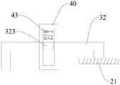
- the guiding plate 41is provided with a guiding groove 42, and two sides of the linkage bar are respectively provided with a guiding block 323, and two guiding blocks 323 are provided. They are fitted in the two guiding grooves 42 respectively.
- the guiding groove 42can restrict the moving direction of the interlocking lever by restricting the moving direction of the guiding block 323, so that the interlocking lever can be moved up and down with the push rod 312.
- the guiding device 40may be more And a plurality of guiding devices 40 are distributed between the two ends of the linkage rod.
- a spring 43may be disposed in the guide groove 42, and the spring 43 provides an elastic force for guiding the block 323 to move downward.
- the elastic forcecan force the linkage rod and the push rod 312 to move downward rapidly after the pressure relief is completed, so that the first magnetic member 21 and the second magnetic member 22 can be magnetically adsorbed quickly, so that the first The two magnetic members 22 quickly seal the pressure relief port 11, thereby improving the reliability of the electric cooking device.
- the linkage 32includes a first pivoting lever 321 and a second pivoting lever 322, and the first pivoting lever 321 and the second pivoting lever 322 are pivotable.
- the grounding memberis disposed on the flip cover 10, and the first pivoting lever 321 and the second pivoting lever 322 are pivotally connected.
- One end of the first pivoting lever 321is abutted against the push rod 312, and the second pivoting lever 322 is The first magnetic member 21 is fixed at one end.
- the driving devicemoves under the pressure in the cooking chamber, and the driving device drives the plugging structure to open the pressure relief port to realize the instantaneous pressure relief of the electric cooking device, thereby enabling the electric cooking device
- the pressure reliefis quick and reliable, and the taste of the food is good.
- the pressure relief mode of the electric cooking deviceis passive pressure relief, and the active control device and the degree need not be provided, so that the electric cooking device can be simple in structure and low in cost.
- the electric cooking devicemay be the electric cooking device of the first aspect embodiment or the second aspect embodiment, and the cooking method of the electric cooking device may include the following steps: the heating device in the crucible heats the food, along with the food Heating, the temperature and pressure in the crucible gradually increase, when the vapor pressure in the crucible reaches a predetermined value, the driving device moves under the action of the vapor pressure, and the driving device Drive the blocking structure to open the pressure relief port.
- the pressure device 20amoves under the action of the steam pressure and drives the plugging structure 30a to open the pressure relief through the linkage device 40a. mouth.
- the driving device 20amoves under the action of the steam pressure, and the driving device 20a drives the blocking structure 30a at least once to open the pressure releasing port.
- the driving device 20acan drive the sealing structure 30a to open the pressure relief port 2 times-6 times, so that a good stirring effect can be achieved, and the food taste can be better.
- the electric cooking deviceis the electric cooking device of the second aspect embodiment
- the pressure device 31moves under the action of the steam pressure and drives the first magnetic member 21 away from the first through the linkage device 32.
- the magnetic member 22is such that the second magnetic member 22 opens the pressure relief opening 11.
- the driving devicemoves under the pressure in the cooking chamber, and the driving device drives the blocking structure to open the pressure releasing port to realize the instantaneous pressure relief of the electric cooking device, thereby making the electricity
- the cooking deviceis quick and reliable, and the food tastes better.
- the pressure relief mode of the electric cooking deviceis passive pressure relief, and the active control device and the degree need not be provided, so that the electric cooking device can be simple in structure and low in cost.
Landscapes
- Engineering & Computer Science (AREA)
- Food Science & Technology (AREA)
- Cookers (AREA)
Abstract
Description
Translated fromChinese本发明涉及厨房电器技术领域,尤其涉及一种电烹饪装置和该电烹饪装置的烹饪方法。The present invention relates to the field of kitchen electrical appliances, and in particular, to an electric cooking device and a cooking method of the electric cooking device.
相关技术中,市面上带压力的饭煲,一般在饭煮好后进行泄压,但是这样饭容易结块,导致饭的口感不好。也有一些饭煲在煮饭过程中主动且强制进行泄压,但是这样饭煲结构复杂,实现功能过程较繁琐。In the related art, a pressure-regulated rice cooker in the market generally discharges pressure after the rice is cooked, but the rice is easily agglomerated, resulting in a bad taste of the rice. There are also some rice cookers that actively and forcibly release pressure during the cooking process, but the rice cooker structure is complicated and the functional process is complicated.
发明内容Summary of the invention
本发明旨在至少在一定程度上解决相关技术中的技术问题之一。为此,本发明提出一种电烹饪装置,该电烹饪装置可以实现瞬间泄压,而且泄压方式为被动泄压,无需主动控制装置和程度,所以该电烹饪装置结构简单且成本低。The present invention aims to solve at least one of the technical problems in the related art to some extent. To this end, the present invention provides an electric cooking device that can achieve instantaneous pressure relief, and the pressure relief mode is passive pressure relief, without the need for active control devices and degrees, so the electric cooking device has a simple structure and low cost.
本发明进一步地提出了一种电烹饪装置的烹饪方法。The invention further proposes a cooking method for an electric cooking device.
根据本发明的电烹饪装置,包括:煲体,所述煲体内限定出烹饪腔;煲盖,所述煲盖设在所述煲体上以打开或关闭所述烹饪腔,所述煲盖上设置有泄压口;封堵结构,所述封堵结构适于设置在所述泄压口处;驱动装置,所述驱动装置设置在所述煲盖上且适于在所述煲体内的压力作用下驱动所述封堵结构打开所述泄压口。An electric cooking apparatus according to the present invention, comprising: a body defining a cooking chamber; a lid, the lid being disposed on the body to open or close the cooking chamber, the lid Provided with a pressure relief port; a plugging structure adapted to be disposed at the pressure relief port; a driving device disposed on the lid and adapted to be in the pressure in the body Actuating the plugging structure to open the pressure relief port.
根据本发明的电烹饪装置,驱动装置在烹饪腔内的压力作用下运动,而且驱动装置带动封堵结构打开泄压口以实现电烹饪装置的瞬间泄压,从而可以使得电烹饪装置泄压迅速且可靠,而且食物的口感较好。另外,电烹饪装置的实现泄压方式为被动泄压,无需设置主动控制装置和程度,从而可以使得电烹饪装置结构简单且成本低。According to the electric cooking device of the present invention, the driving device moves under the pressure in the cooking chamber, and the driving device drives the blocking structure to open the pressure releasing port to realize the instantaneous pressure relief of the electric cooking device, thereby enablingThe electric cooking device is quick and reliable, and the taste of the food is good. In addition, the pressure relief mode of the electric cooking device is passive pressure relief, and the active control device and the degree need not be provided, so that the electric cooking device can be simple in structure and low in cost.
另外,根据本发明的电烹饪装置还可以具有以下附加技术特征:In addition, the electric cooking device according to the invention may also have the following additional technical features:
在本发明的一些示例中,所述驱动装置包括:压力装置,所述压力装置与所述烹饪腔相连通且适于在所述煲体内的压力作用下向上移动;联动装置,所述联动装置与所述压力装置相连且适于随所述压力装置移动时驱动所述封堵结构打开所述泄压口。In some examples of the present invention, the driving device includes: a pressure device in communication with the cooking chamber and adapted to move upward under pressure of the crucible; a linkage, the linkage Connected to the pressure device and adapted to drive the occlusion structure to open the pressure relief port as the pressure device moves.
在本发明的一些示例中,所述煲盖上形成有蒸汽口,所述压力装置包括:第一座体,所述第一座体安装在所述煲盖上;第一推杆,所述第一推杆配合在所述第一座体上且设置有用于密封所述蒸汽口并位于所述蒸汽口上方的第一密封圈,所述联动装置位于所述第一推杆的上端,所述第一推杆在向上移动时适于驱动所述联动装置带动所述封堵结构打开所述泄压口。In some examples of the present invention, the clamshell is formed with a steam port, the pressure device includes: a first seat body, the first seat body is mounted on the flip cover; a first push rod, the a first push rod is fitted on the first seat body and is provided with a first sealing ring for sealing the steam port and located above the steam port, the linkage device is located at an upper end of the first push rod, The first push rod is adapted to drive the linkage device to drive the blocking structure to open the pressure relief port when moving upward.
在本发明的一些示例中,所述封堵结构为泄压阀,所述泄压阀包括:第二座体,所述第二座体安装在所述煲盖上;第二推杆,所述第二推杆配合在所述第二座体上且设置有密封在所述泄压口并位于所述泄压口下方的第二密封圈,所述联动装置位于所述第二推杆的上端,并且在所述第一推杆在向上移动时所述第一推杆通过联动装置驱动所述第二推杆向下运动,以使所述泄压口打开。In some examples of the present invention, the plugging structure is a pressure relief valve, the pressure relief valve includes: a second seat body, the second seat body is mounted on the top cover; and the second push rod, The second push rod is fitted on the second seat body and is provided with a second sealing ring sealed at the pressure release port and located below the pressure release port, and the linkage device is located at the second push rod An upper end, and the first push rod drives the second push rod to move downward by the linkage when the first push rod moves upward to open the pressure relief opening.
在本发明的一些示例中,所述驱动装置包括:压力装置,所述压力装置与所述烹饪腔相连通且适于在所述煲体内的压力作用下向上移动;联动装置,所述联动装置与所述压力装置相连;第一磁性件,所述第一磁性件与所述联动装置相连,所述封堵结构设置成第二磁性件,所述联动装置适于在所述压力装置移动时带动所述第一磁性件移动以驱动所述第二磁性件,从而使所述第二磁性件打开所述泄压口。In some examples of the present invention, the driving device includes: a pressure device in communication with the cooking chamber and adapted to move upward under pressure of the crucible; a linkage, the linkage Connected to the pressure device; a first magnetic member, the first magnetic member being coupled to the linkage, the occlusion structure being configured as a second magnetic member, the linkage being adapted to move when the pressure device is moved Driving the first magnetic member to move to drive the second magnetic member, thereby causing the second magneticThe piece opens the pressure relief port.
在本发明的一些示例中,所述煲盖包括座置体,所述泄压口形成在所述座置体上,所述第二磁性件设置在所述座置体内部空间,所述第一磁性件设置在所述座置体外,所述联动装置适于在所述压力装置移动时带动所述第一磁性件移动以驱动所述第一磁性件远离所述第二磁性件,从而使所述第二磁性件打开所述泄压口。In some examples of the present invention, the flip cover includes a seat body, the pressure relief port is formed on the seat body, and the second magnetic member is disposed in the seat body inner space, the first a magnetic member disposed outside the seat, the linkage being adapted to move the first magnetic member to move the first magnetic member away from the second magnetic member when the pressure device moves, thereby enabling The second magnetic member opens the pressure relief port.
在本发明的一些示例中,所述煲盖上形成有蒸汽口,所述压力装置包括:座体,所述座体安装在所述煲盖上;推杆,所述推杆适于打开或关闭所述蒸汽口且配合在所述座体上,所述推杆的上端与所述联动装置相连;弹性件,所述弹性件设置在所述推杆和所述座体之间。In some examples of the present invention, the clamshell is formed with a steam port, the pressure device includes: a seat body, the seat body is mounted on the flip cover; a push rod, the push rod is adapted to be opened or Closing the steam port and fitting on the seat body, the upper end of the push rod is connected with the linkage device; and the elastic member is disposed between the push rod and the seat body.
在本发明的一些示例中,所述联动装置设置成联动杆,所述联动杆呈倒U形,所述联动杆的一端固定在所述第一磁性件上且另一端止抵在所述推杆上;所述电烹饪装置还包括:引导装置,所述引导装置设置在所述煲盖上且用于引导所述联动杆在上下方向上移动。In some examples of the present invention, the linkage is provided as a linkage rod, the linkage rod is in an inverted U shape, one end of the linkage rod is fixed on the first magnetic member and the other end is abutted on the push The electric cooking device further includes: a guiding device disposed on the flip cover and configured to guide the interlocking lever to move in an up and down direction.
在本发明的一些示例中,所述引导装置包括两个相对的引导板,所述引导板上设置有引导槽,所述联动杆的两侧分别设置有引导块且分别配合在两个所述引导槽内。In some examples of the present invention, the guiding device includes two opposite guiding plates, the guiding plate is provided with a guiding groove, and two sides of the linkage bar are respectively provided with guiding blocks and respectively matched in two Guide the slot.
在本发明的一些示例中,所述联动装置包括:第一枢转杆和第二枢转杆,所述第一枢转杆和所述第二枢转杆可枢转地设置在所述煲盖上且所述第一枢转杆和所述第二枢转杆可枢转地连接,所述第一枢转杆的一端止抵所述推杆,所述第二枢转杆的一端固定所述第一磁性件。In some examples of the invention, the linkage includes: a first pivoting lever and a second pivoting lever, the first pivoting lever and the second pivoting lever being pivotally disposed on the cymbal Covered and the first pivoting lever and the second pivoting lever are pivotally connected, one end of the first pivoting lever abuts the pushrod, and one end of the second pivoting pole is fixed The first magnetic member.
根据本发明的电烹饪装置的烹饪方法,电烹饪装置为上述的电烹饪装置,烹饪方法包括以下步骤:S1、所述煲体内的加热装置加热食物;S2、所述煲体内的蒸汽压力达到预定值时,所述驱动装置在蒸汽压力的作用下运动且带动所述封堵结构运动以打开所述泄压口。According to the cooking method of the electric cooking device of the present invention, the electric cooking device is the above-described electric cooking device, and the cooking method comprises the steps of: S1, the heating device in the crucible body heats the food; S2, the carcassWhen the internal steam pressure reaches a predetermined value, the driving device moves under the action of the steam pressure and drives the blocking structure to move to open the pressure relief port.
根据本发明的电烹饪装置的烹饪方法,驱动装置在烹饪腔内的压力作用下运动,而且驱动装置带动封堵结构打开泄压口以实现电烹饪装置的瞬间泄压,从而可以使得电烹饪装置泄压迅速且可靠,而且食物的口感较好。另外,电烹饪装置的实现泄压方式为被动泄压,无需设置主动控制装置和程度,从而可以使得电烹饪装置结构简单且成本低。According to the cooking method of the electric cooking device of the present invention, the driving device moves under the pressure in the cooking chamber, and the driving device drives the plugging structure to open the pressure releasing port to realize the instantaneous pressure relief of the electric cooking device, thereby enabling the electric cooking device The pressure relief is quick and reliable, and the taste of the food is good. In addition, the pressure relief mode of the electric cooking device is passive pressure relief, and the active control device and the degree need not be provided, so that the electric cooking device can be simple in structure and low in cost.
在本发明的一些示例中,所述驱动装置包括:压力装置和联动装置,在所述步骤S2中,所述煲体内的蒸汽压力达到预定值时,所述压力装置在蒸汽压力的作用下运动并通过联动装置带动所述封堵结构打开所述泄压口。In some examples of the present invention, the driving device includes: a pressure device and a linkage device, and in the step S2, when the steam pressure in the crucible reaches a predetermined value, the pressure device moves under the action of steam pressure And driving the plugging structure to open the pressure relief port by a linkage device.
在本发明的一些示例中,所述驱动装置包括:压力装置、联动装置和第一磁性件,所述封堵结构设置成第二磁性件,在所述步骤S2中,所述煲体内的蒸汽压力达到预定值时,所述压力装置在蒸汽压力的作用下运动并通过联动装置带动所述第一磁性件远离所述第二磁性件,以使第二磁性件打开所述泄压口。In some examples of the present invention, the driving device includes: a pressure device, a linkage, and a first magnetic member, the blocking structure is disposed as a second magnetic member, and in the step S2, the steam in the crucible When the pressure reaches a predetermined value, the pressure device moves under the action of the vapor pressure and drives the first magnetic member away from the second magnetic member through the linkage device, so that the second magnetic member opens the pressure relief port.
在本发明的一些示例中,所述驱动装置在蒸汽压力的作用下运动且至少一次带动所述封堵结构运动以打开所述泄压口。In some examples of the invention, the drive device moves under the action of steam pressure and at least once drives the occlusion structure to open the pressure relief port.
图1是根据本发明第一方面实施例的电烹饪装置的局部示意图;1 is a partial schematic view of an electric cooking apparatus in accordance with an embodiment of the first aspect of the present invention;
图2是根据本发明第二方面实施例的电烹饪装置的煲盖的一个剖视图;Figure 2 is a cross-sectional view of a flip cover of an electric cooking device in accordance with an embodiment of the second aspect of the present invention;
图3是图2中区域A的放大图;Figure 3 is an enlarged view of a region A in Figure 2;
图4是根据本发明第二方面实施例的电烹饪装置的煲盖的另一个剖视图;Figure 4 is another cross-sectional view of a flip cover of an electric cooking device in accordance with an embodiment of the second aspect of the present invention;
图5是根据本发明第二方面实施例的电烹饪装置的一种引导装置的布置示意图;Figure 5 is a schematic view showing the arrangement of a guiding device of an electric cooking device according to an embodiment of the second aspect of the present invention;
图6是根据本发明第二方面实施例的电烹饪装置的另一种引导装置的布置示意图;Figure 6 is a schematic view showing the arrangement of another guiding device of the electric cooking device according to the embodiment of the second aspect of the present invention;
图7是根据本发明第二方面实施例的电烹饪装置的联动装置的布置示意图。Figure 7 is a schematic view showing the arrangement of a linkage of an electric cooking apparatus according to an embodiment of the second aspect of the present invention.
下面详细描述本发明的实施例,所述实施例的示例在附图中示出。下面通过参考附图描述的实施例是示例性的,旨在用于解释本发明,而不能理解为对本发明的限制。Embodiments of the invention are described in detail below, examples of which are illustrated in the accompanying drawings. The embodiments described below with reference to the drawings are intended to be illustrative of the invention and are not to be construed as limiting.
下面参考图1详细描述根据本发明第一方面实施例的电烹饪装置,电烹饪装置可以为电饭煲、电压力锅和电炖锅等。An electric cooking apparatus according to an embodiment of the first aspect of the present invention, which may be a rice cooker, an electric pressure cooker, an electric cooker, or the like, is described in detail below with reference to FIG.
根据本发明实施例的电烹饪装置可以包括:煲体、煲盖10a、驱动装置和封堵结构30a,煲体内限定出烹饪腔,煲盖10a设在煲体上以打开或关闭烹饪腔,压力装置20a与烹饪腔相连通,煲盖10a上设置有蒸汽口11a和泄压口12a,其中蒸汽口11a和泄压口12a可以在煲盖10a上间隔开设置,蒸汽口11a和泄压口12a可以分别与烹饪腔连通。An electric cooking apparatus according to an embodiment of the present invention may include a body, a
驱动装置设置在煲盖10a上,而且驱动装置适于在煲体内的压力作用下驱动封堵结构30a打开泄压口12a。其中,驱动装置可以包括压力装置20a和联动装置40a,压力装置20a与烹饪腔相连通,煲压力装置20a适于打开或者关闭蒸汽口11a,封堵结构30a适于打开或者关闭泄压口12a,联动装置40a与压力装置20a相连,而且联动装置40a适于随压力装置20a移动时驱动封堵结构30a打开泄压口12a。换言之,联动装置40a配合在压力装置20a和封堵结构30a之间,而且压力装置20a设置成在打开蒸汽口11a时通过联动装置40a带动封堵结构30a打开泄压口12a。也就是说,相对于封堵结构30a来说,压力装置20a属于主动泄压阀,这样压力装置20a打开蒸汽口11a时,封堵结构30a可以同时打开泄压口12a,从而可以使得泄压面积增大,可以实现电烹饪装置的快速泄压,进而可以使得烹饪腔内的食物得到充分沸腾搅拌,可以使得食物受热更加均匀。The driving device is disposed on the
其中,压力装置20a适于在烹饪腔的压力作用下打开蒸汽口11a。可以理解的是,在电烹饪装置开始加热食物时,烹饪腔内的压力较小,压力装置20a关闭蒸汽口11a,封堵结构30a关闭泄压口12a,当烹饪腔内的蒸汽压力达到预定值时,压力装置20a在烹饪腔的压力作用下打开蒸汽口11a,从而蒸汽口11a处于泄压状态,压力装置20a可以通过联动装置40a带动封堵结构30a打开泄压口12a,从而可以使得蒸汽口11a和泄压口12a同时进行泄压,进而可以使得电烹饪装置快速泄压。Among them, the
可选地,如图1所示,压力装置20a适于密封在蒸汽口11a的上侧,封堵结构30a适于密封泄压口12a的下侧。这样在烹饪腔内的压力达到预定值时,烹饪腔内的压力可以向上推动压力装置20a打开蒸汽口11a,而烹饪腔内的压力无法直接向上推动封堵结构30a打开泄压口12a,从而可以使得电烹饪装置泄压稳定且可靠。Alternatively, as shown in Fig. 1, the
根据本发明的一个具体实施例,如图1所示,压力装置20a可以包括:第一座体21a和第一推杆22a,第一座体21a安装在煲盖10a上,第一推杆22a配合在第一座体21a上,而且第一推杆22a设置有用于密封蒸汽口11a并位于蒸汽口11a上方的第一密封圈23a,联动装置40a位于第一推杆22a的上端,第一推杆22a在向上移动时适于驱动联动装置40a带动封堵结构30a打开泄压口12a。第一座体21a可以通过紧固件或者卡扣结构安装在煲盖10a上,第一推杆22a可以相对第一座体21a上下移动,第一推杆22a上的第一密封圈23a可以用于密封蒸汽口11a,从而可以使得压力装置20a关闭蒸汽口11a。当第一推杆22a带动第一密封圈23a向上移动时,第一密封圈23a打开蒸汽口11a。According to a specific embodiment of the present invention, as shown in FIG. 1, the
第一密封圈23a可以由耐热材料制成,例如,第一密封圈23a可以为橡胶件,其中,第一密封圈23a的径向尺寸可以大于蒸汽口11a的径向尺寸。这样第一密封圈23a在关闭蒸汽口11a时,第一密封圈23a可以完全密封住蒸汽口11a,从而可以避免烹饪腔内的蒸汽通过第一密封圈23a和煲盖10a之间的缝隙流出,进而可以保证电烹饪装置的工作可靠性。进一步地,第一密封圈23a上可以设置有径向尺寸大于蒸汽口11a的径向尺寸且向下凸出的凸起环。换言之,在第一密封圈23a密封蒸汽口11a时,凸起环环绕在蒸汽口11a的外侧。通过设置凸起环,可以避免第一密封圈23a和煲盖10a之间产生缝隙,从而可以进一步地提高电烹饪装置的可靠性。The
可选地,电烹饪装置还可以包括:弹性装置50a,弹性装置50a设置在第一推杆22a和第一座体21a之间以提供给第一密封圈23a密封蒸汽口11a的弹性力。可以理解的是,在烹饪腔内的压力小于弹性装置50a提供给第一密封圈23a的弹性力时,第一密封圈23a密封蒸汽口11a,在烹饪腔内的压力大于弹性装置50a提供给第一密封圈23a的弹性力时,第一密封圈23a打开蒸汽口11a,而且第一推杆22a向上移动已通过联动装置40a带动封堵结构30a打开泄压口12a。Alternatively, the electric cooking device may further include: an
根据本发明的另一个具体实施例,封堵结构30a为泄压阀,泄压阀可以包括:第二座体31a和第二推杆32a,第二座体31a安装在煲盖10a上,第二推杆32a配合在第二座体31a上,而且第二推杆32a设置有密封在泄压口12a并位于泄压口12a下方的第二密封圈33a,联动装置40a位于第二推杆32a的上端,并且在第一推杆22a在向上移动时第一推杆22a通过联动装置40a驱动第二推杆32a向下运动,以使泄压口12a打开。可以理解的是,第二密封圈33a密封泄压口12a的下侧,当联动装置40a驱动第二推杆32a向下移动时,第二密封圈33a向下移动以打开泄压口12a,从而可以使得泄压口12a与蒸汽口11a同时打开,可以使得电烹饪装置快速泄压。According to another embodiment of the present invention, the plugging
其中,第二密封圈33a和第一密封圈23a结构可以相同。例如,第二密封圈33a的径向尺寸大于泄压口12a的径向尺寸,第二密封圈33a上设置有凸起环。The structure of the
根据本发明的一个可选实施例,联动装置40a可以构成为杠杆,杠杆的两端分别位于第一推杆22a和第二推杆32a的上端。这样在第一推杆22a向上移动时,第一推杆22a的上端可以向上推动杠杆的一端向上移动,从而可以使得杠杆的另一端向下移动,向下移动的杠杆的另一端可以向下压迫第二推杆32a的上端,第二推杆32a可以向下移动,进而可以使得第二密封圈33a打开泄压口12a,这样蒸汽口11a和泄压口12a同时泄压。According to an alternative embodiment of the invention, the
可选地,第一推杆22a的上端和第二推杆32a的上端分别与杠杆相连。这样第一推杆22a的上端与杠杆的一端可以枢转地连接,第二推杆32a的上端与杠杆的另一端可以枢转地连接。Alternatively, the upper end of the
或者可选地,如图1所示,第一推杆22a的上端和第二推杆32a的上端分别适于与杠杆抵接配合。第一推杆22a的上端可以止抵在杠杆的一端,第二推杆32a的上端可以止抵在杠杆的另一端。需要说明的是,在第二密封圈33a打开泄压口12a且电烹饪装置完成泄压后,第二推杆32a和第二密封圈33a可以在烹饪腔内的蒸汽压力作用下重新关闭泄压口12a。Alternatively, as shown in Fig. 1, the upper end of the
可选地,蒸汽口11a和泄压口12a的径向尺寸可以不同。例如,蒸汽口11a的径向尺寸可以大于泄压口12a的径向尺寸,例如,蒸汽口11a的径向尺寸可以小于泄压口12a的径向尺寸。或者可选地,蒸汽口11a与泄压口12a的径向尺寸可以相同。Alternatively, the radial size of the
下面结合图2-图7详细描述根据本发明第二方面实施例的电烹饪装置。An electric cooking apparatus according to an embodiment of the second aspect of the present invention will be described in detail below with reference to Figs.
根据本发明实施例的电烹饪装置可以包括:煲体、煲盖10、封堵结构和驱动装置30,煲体内限定出烹饪腔,煲盖10设在煲体上以打开或关闭烹饪腔,煲盖10上设置有泄压口11,其中泄压口11与烹饪腔相连通。封堵结构适于设置在泄压口11处,驱动装置设置在煲盖10上,而且驱动装置适于在煲体内的压力作用下驱动封堵结构打开泄压口12。An electric cooking device according to an embodiment of the present invention may include a body, a
下面详细描述一种可选的驱动装置30的布置形式。驱动装置30可以包括:压力装置31、联动装置32和第一磁性件21,封堵结构可以为第二磁性件22,压力装置31与烹饪腔相连通,压力装置31适于在煲体内的压力作用下向上移动,例如,压力装置31适于在烹饪腔内压力值达到预定值时向上移动,联动装置32连接在压力装置31和第一磁性件21之间以在压力装置31向上移动时带动第一磁性件21移动以驱动第一磁性件21远离第二磁性件22。可以理解的是,压力装置31可以感知烹饪腔内的压力,当烹饪腔内的压力达到预定值时,压力装置31可以向上推动联动装置32,从而可以使得联动装置32的另一端带动第一磁性件21向上移动,进而可以使得第一磁性件21和第二磁性件22彼此远离,可以使得第二磁性件22打开泄压口11。其中,预定值可以根据电烹饪装置的情况进行设定。An alternative arrangement of the
第一磁性件21和第二磁性件22分别位于泄压口11的两侧以在磁吸力作用下使得第二磁性件22密封泄压口11,可以理解的是,第一磁性件21和第二磁性件22分别位于泄压口11的两侧,这样当第一磁性件21和第二磁性件22距离较近时,第一磁性件21和第二磁性件22相互吸附,从而可以使得第二磁性件22吸附在泄压口11处,进而第二磁性件22可以密封泄压口11。The first
如图2和图4所示,煲盖10可以包括座置体12,例如,座置体12可以为球座,泄压口11形成在座置体12上,第二磁性件22设置在座置体内部空间,第一磁性件21设置在座置体12外。座置体内部空间可以由座置体12和煲盖10的一部分共同限定出,泄压口11形成在座置体12的上表面,第一磁性件21和第二磁性件22之间的磁吸力可以克服第二磁性件22的重力将第二磁性件22吸附在泄压口11处。可选地,第一磁性件21可以为磁铁,而且第二磁性件22可以为金属球。如图2所示,磁铁可以构造为板状结构,这样可以便于第一磁性件21和第二磁性件22之间的吸附。As shown in FIG. 2 and FIG. 4, the
当第一磁性件21远离第二磁性件22时,这样随着第一磁性件21和第二磁性件22之间距离的变大,第一磁性件21和第二磁性件22之间的磁吸力变小,直至第二磁性件22从泄压口11处下落以打开泄压口11,此时烹饪腔进行泄压,从而可以使得电烹饪装置在煮饭过程中进行自动泄压,可以使得食物进行翻滚,可以使得食物受热更加均匀,可以提升食物的口感。When the first
如图3所示,煲盖10上形成有蒸汽口,压力装置31可以包括:座体311、推杆312和弹性件313,座体311安装在煲盖10上,推杆312适于打开或关闭蒸汽口,而且推杆312配合在座体311上,推杆312的上端与联动装置32相连,弹性件313设置在推杆312和座体311之间。当烹饪腔内的压力达到预定值时,推杆312可以克服弹性件313的弹性力向上移动,从而联动装置32同步向上移动并带动第一磁性件21,第一磁性件21远离第二磁性件22,第二磁性件22打开泄压口11。可以理解的是,当泄压后,推杆312向下移动,第一磁性件21向下移动,并且第一磁性件21重新将第二磁性件22吸附在泄压口11上以使得第二磁性件22密封泄压口11。其中,压力装置31上可以设置有开关,当推杆312向上移动时,开关关闭电烹饪装置的加热系统,从而可以使得电烹饪装置停止加热。当第二磁性件22密封泄压口11后,开关控制加热系统开始工作。As shown in FIG. 3, a steam port is formed on the
根据本发明的一个具体实施例,如图2和图4所示,联动装置32可以设置成联动杆,联动杆呈倒U形,联动杆的一端固定在第一磁性件21上,而且联动杆的另一端止抵在推杆312上。由此,推杆312可以通过联动杆同步带动第一磁性件21向上或者向下移动。According to an embodiment of the present invention, as shown in FIG. 2 and FIG. 4, the
可选地,如图2和图4所示,电烹饪装置还可以包括:引导装置40,引导装置40设置在煲盖10上,而且引导装置40用于引导联动杆在上下方向上移动。引导装置40可以保证联动杆上下移动,从而可以使得电烹饪装置工作可靠且稳定。Alternatively, as shown in FIGS. 2 and 4, the electric cooking device may further include: a guiding
如图2和图4所示,引导装置40可以包括两个相对的引导板41,引导板41上设置有引导槽42,联动杆的两侧分别设置有引导块323,而且两个引导块323分别配合在两个引导槽42内。引导槽42可以通过限制引导块323的移动方向来限制联动杆的移动方向,从而可以使得联动杆随着推杆312上下移动。As shown in FIG. 2 and FIG. 4, the guiding
为了提高电烹饪装置的结构稳定性,如图5所示,引导装置40可以为多个,而且多个引导装置40在联动杆的两端之间分布。In order to improve the structural stability of the electric cooking device, as shown in FIG. 5, the guiding
进一步地,如图6所示,引导槽42内可以设置有弹簧43,弹簧43提供引导块323向下移动的弹性力。通过设置弹簧43,可以使得在烹饪腔完成泄压后弹性力可以迫使联动杆和推杆312快速向下移动,从而可以使得第一磁性件21和第二磁性件22快速磁性吸附,以使得第二磁性件22快速密封泄压口11,进而可以提高电烹饪装置的可靠性。Further, as shown in FIG. 6, a
根据本发明的另一个具体实施例,如图7所示,联动装置32包括:第一枢转杆321和第二枢转杆322,第一枢转杆321和第二枢转杆322可枢转地设置在煲盖10上,而且第一枢转杆321和第二枢转杆322可枢转地连接,第一枢转杆321的一端止抵推杆312,第二枢转杆322的一端固定第一磁性件21。当推杆312向上移动时,第一枢转杆321顺时针转动,第二枢转杆322逆时针转动,从而可以使得第一磁性件21向远离第二磁性件22的方向移动,进而可以使得第二磁性件22打开泄压口11。According to another embodiment of the present invention, as shown in FIG. 7, the
根据本发明上述实施例的电烹饪装置,驱动装置在烹饪腔内的压力作用下运动,而且驱动装置带动封堵结构打开泄压口以实现电烹饪装置的瞬间泄压,从而可以使得电烹饪装置泄压迅速且可靠,而且食物的口感较好。另外,电烹饪装置的实现泄压方式为被动泄压,无需设置主动控制装置和程度,从而可以使得电烹饪装置结构简单且成本低。According to the electric cooking device of the above embodiment of the present invention, the driving device moves under the pressure in the cooking chamber, and the driving device drives the plugging structure to open the pressure relief port to realize the instantaneous pressure relief of the electric cooking device, thereby enabling the electric cooking device The pressure relief is quick and reliable, and the taste of the food is good. In addition, the pressure relief mode of the electric cooking device is passive pressure relief, and the active control device and the degree need not be provided, so that the electric cooking device can be simple in structure and low in cost.
下面结合附图详细描述根据本发明实施例的电烹饪装置的烹饪方法。A cooking method of an electric cooking apparatus according to an embodiment of the present invention will be described in detail below with reference to the accompanying drawings.
根据本发明实施例的电烹饪装置可以为上述第一方面实施例或第二方面实施例的电烹饪装置,电烹饪装置的烹饪方法可以包括以下步骤:煲体内的加热装置加热食物,随着食物的加热,煲体内的温度和压力逐渐升高,当煲体内的蒸汽压力达到预定值时,驱动装置在蒸汽压力的作用下运动,而且驱动装置带动封堵结构运动以打开泄压口。The electric cooking device according to the embodiment of the present invention may be the electric cooking device of the first aspect embodiment or the second aspect embodiment, and the cooking method of the electric cooking device may include the following steps: the heating device in the crucible heats the food, along with the food Heating, the temperature and pressure in the crucible gradually increase, when the vapor pressure in the crucible reaches a predetermined value, the driving device moves under the action of the vapor pressure, and the driving deviceDrive the blocking structure to open the pressure relief port.
当电烹饪装置为上述第一方面实施例的电烹饪装置时,煲体内的蒸汽压力达到预定值时,压力装置20a在蒸汽压力的作用下运动并通过联动装置40a带动封堵结构30a打开泄压口。例如,驱动装置20a在蒸汽压力的作用下运动,而且驱动装置20a至少一次带动封堵结构30a运动以打开泄压口。优选地,驱动装置20a可以带动封堵结构30a打开泄压口2次-6次,从而可以达到良好的搅拌效果,进而可以使得食物的口感较好。When the electric cooking device is the electric cooking device of the first aspect embodiment, when the steam pressure in the crucible reaches a predetermined value, the
当电烹饪装置为上述第二方面实施例的电烹饪装置时,煲体内的蒸汽压力达到预定值时,压力装置31在蒸汽压力的作用下运动并通过联动装置32带动第一磁性件21远离第二磁性件22,以使第二磁性件22打开泄压口11。When the electric cooking device is the electric cooking device of the second aspect embodiment, when the steam pressure in the crucible reaches a predetermined value, the
根据本发明实施例的电烹饪装置的烹饪方法,驱动装置在烹饪腔内的压力作用下运动,而且驱动装置带动封堵结构打开泄压口以实现电烹饪装置的瞬间泄压,从而可以使得电烹饪装置泄压迅速且可靠,而且食物的口感较好。另外,电烹饪装置的实现泄压方式为被动泄压,无需设置主动控制装置和程度,从而可以使得电烹饪装置结构简单且成本低。According to the cooking method of the electric cooking device according to the embodiment of the present invention, the driving device moves under the pressure in the cooking chamber, and the driving device drives the blocking structure to open the pressure releasing port to realize the instantaneous pressure relief of the electric cooking device, thereby making the electricity The cooking device is quick and reliable, and the food tastes better. In addition, the pressure relief mode of the electric cooking device is passive pressure relief, and the active control device and the degree need not be provided, so that the electric cooking device can be simple in structure and low in cost.
在本说明书的描述中,参考术语“一个实施例”、“一些实施例”、“示例”、“具体示例”、或“一些示例”等的描述意指结合该实施例或示例描述的具体特征、结构、材料或者特点包含于本发明的至少一个实施例或示例中。在本说明书中,对上述术语的示意性表述不必须针对的是相同的实施例或示例。而且,描述的具体特征、结构、材料或者特点可以在任一个或多个实施例或示例中以合适的方式结合。此外,在不相互矛盾的情况下,本领域的技术人员可以将本说明书中描述的不同实施例或示例以及不同实施例或示例的特征进行结合和组合。In the description of the present specification, the description with reference to the terms "one embodiment", "some embodiments", "example", "specific example", or "some examples" and the like means a specific feature described in connection with the embodiment or example. A structure, material or feature is included in at least one embodiment or example of the invention. In the present specification, the schematic representation of the above terms is not necessarily directed to the same embodiment or example. Furthermore, the particular features, structures, materials, or characteristics described may be combined in a suitable manner in any one or more embodiments or examples. In addition, various embodiments or examples described in the specification, as well as features of various embodiments or examples, may be combined and combined.
尽管上面已经示出和描述了本发明的实施例,可以理解的是,上述实施例是示例性的,不能理解为对本发明的限制,本领域的普通技术人员在本发明的范围内可以对上述实施例进行变化、修改、替换和变型。Although the embodiments of the present invention have been shown and described, it is understood that the above-described embodiments are illustrative and are not to be construed as limiting the scope of the invention. The embodiments are subject to variations, modifications, substitutions and variations.
Claims (14)
Translated fromChineseApplications Claiming Priority (4)
| Application Number | Priority Date | Filing Date | Title |
|---|---|---|---|
| CN201620909028.1UCN206371836U (en) | 2016-08-19 | 2016-08-19 | Electric cooker |
| CN201620909028.1 | 2016-08-19 | ||
| CN201610692425.2ACN107752749B (en) | 2016-08-19 | 2016-08-19 | Electric cooking device and cooking method thereof |
| CN201610692425.2 | 2016-08-19 |
Publications (1)
| Publication Number | Publication Date |
|---|---|
| WO2018032541A1true WO2018032541A1 (en) | 2018-02-22 |
Family
ID=61196250
Family Applications (1)
| Application Number | Title | Priority Date | Filing Date |
|---|---|---|---|
| PCT/CN2016/097693CeasedWO2018032541A1 (en) | 2016-08-19 | 2016-08-31 | Electric cooking device, and cooking method for same |
Country Status (1)
| Country | Link |
|---|---|
| WO (1) | WO2018032541A1 (en) |
Cited By (14)
| Publication number | Priority date | Publication date | Assignee | Title |
|---|---|---|---|---|
| CN109431254A (en)* | 2018-06-26 | 2019-03-08 | 浙江苏泊尔家电制造有限公司 | Cooking apparatus |
| CN109452840A (en)* | 2018-06-26 | 2019-03-12 | 浙江苏泊尔家电制造有限公司 | Cooking apparatus |
| CN110013163A (en)* | 2019-05-08 | 2019-07-16 | 珠海格力电器股份有限公司 | Cooking appliance and pressure regulating device |
| US10390656B2 (en) | 2017-08-09 | 2019-08-27 | Sharkninja Operating Llc | Cooking device and components thereof |
| USD873602S1 (en) | 2018-08-09 | 2020-01-28 | Sharkninja Operating Llc | Lid part of a food preparation device |
| USD874211S1 (en) | 2018-08-09 | 2020-02-04 | Sharkninja Operating Llc | Food preparation device and parts thereof |
| USD903413S1 (en) | 2018-08-09 | 2020-12-01 | Sharkninja Operating Llc | Cooking basket |
| USD914436S1 (en) | 2018-06-19 | 2021-03-30 | Sharkninja Operating Llc | Air diffuser with food preparation pot |
| USD918654S1 (en) | 2019-06-06 | 2021-05-11 | Sharkninja Operating Llc | Grill plate |
| USD922126S1 (en) | 2019-06-06 | 2021-06-15 | Sharkninja Operating Llc | User interface for a food preparation device |
| US11033146B2 (en) | 2019-02-25 | 2021-06-15 | Sharkninja Operating Llc | Cooking device and components thereof |
| US11134808B2 (en) | 2020-03-30 | 2021-10-05 | Sharkninja Operating Llc | Cooking device and components thereof |
| USD932833S1 (en) | 2018-08-09 | 2021-10-12 | Sharkninja Operating Llc | Reversible cooking rack |
| US11751710B2 (en) | 2019-02-25 | 2023-09-12 | Sharkninja Operating Llc | Guard for cooking system |
Citations (5)
| Publication number | Priority date | Publication date | Assignee | Title |
|---|---|---|---|---|
| JP4198180B2 (en)* | 2002-06-24 | 2008-12-17 | 三洋電機株式会社 | Pressure cooker |
| CN102406432A (en)* | 2011-10-12 | 2012-04-11 | 湖北益都电器有限公司 | Multifunctional electric cooker |
| CN203762850U (en)* | 2014-01-24 | 2014-08-13 | 美的集团股份有限公司 | Upper cover of electric cooker and electric cooker |
| CN205094151U (en)* | 2015-08-19 | 2016-03-23 | 上海纯米电子科技有限公司 | Electric rice cooker cover board with air bleeding valve and relief valve |
| CN205125972U (en)* | 2015-09-25 | 2016-04-06 | 佛山市顺德区美的电热电器制造有限公司 | Upper cover subassembly and cooking utensil |
- 2016
- 2016-08-31WOPCT/CN2016/097693patent/WO2018032541A1/ennot_activeCeased
Patent Citations (5)
| Publication number | Priority date | Publication date | Assignee | Title |
|---|---|---|---|---|
| JP4198180B2 (en)* | 2002-06-24 | 2008-12-17 | 三洋電機株式会社 | Pressure cooker |
| CN102406432A (en)* | 2011-10-12 | 2012-04-11 | 湖北益都电器有限公司 | Multifunctional electric cooker |
| CN203762850U (en)* | 2014-01-24 | 2014-08-13 | 美的集团股份有限公司 | Upper cover of electric cooker and electric cooker |
| CN205094151U (en)* | 2015-08-19 | 2016-03-23 | 上海纯米电子科技有限公司 | Electric rice cooker cover board with air bleeding valve and relief valve |
| CN205125972U (en)* | 2015-09-25 | 2016-04-06 | 佛山市顺德区美的电热电器制造有限公司 | Upper cover subassembly and cooking utensil |
Cited By (76)
| Publication number | Priority date | Publication date | Assignee | Title |
|---|---|---|---|---|
| US11627834B2 (en) | 2017-08-09 | 2023-04-18 | Sharkninja Operating Llc | Cooking system for cooking food |
| US11363910B2 (en) | 2017-08-09 | 2022-06-21 | Sharkninja Operating Llc | Cooking device and components thereof |
| US11889950B2 (en) | 2017-08-09 | 2024-02-06 | Sharkninja Operating Llc | Cooking device and components thereof |
| US10390656B2 (en) | 2017-08-09 | 2019-08-27 | Sharkninja Operating Llc | Cooking device and components thereof |
| US10405698B2 (en) | 2017-08-09 | 2019-09-10 | Sharkninja Operating Llc | Cooking device and components thereof |
| US10405697B2 (en) | 2017-08-09 | 2019-09-10 | Sharkninja Operating Llc | Cooking device and components thereof |
| US10413122B2 (en) | 2017-08-09 | 2019-09-17 | Sharkninja Operating Llc | Cooking device and components thereof |
| US10413121B2 (en) | 2017-08-09 | 2019-09-17 | Sharkninja Operating Llc | Cooking device and components thereof |
| US10485378B2 (en) | 2017-08-09 | 2019-11-26 | Sharkninja Operating Llc | Cooking device and components thereof |
| US11759049B2 (en) | 2017-08-09 | 2023-09-19 | Sharkninja Operating Llc | Cooking device and components thereof |
| US11759048B2 (en) | 2017-08-09 | 2023-09-19 | Sharkninja Operating Llc | Cooking device and components thereof |
| US11547242B2 (en) | 2017-08-09 | 2023-01-10 | Sharkninja Operating Llc | Cooking device and components thereof |
| US11109710B2 (en) | 2017-08-09 | 2021-09-07 | Sharkninja Operating Llc | Cooking device and components thereof |
| US11547243B2 (en) | 2017-08-09 | 2023-01-10 | Sharkninja Operating Llc | Cooking device and components thereof |
| US11445856B2 (en) | 2017-08-09 | 2022-09-20 | Sharkninja Operating Llc | Cooking device and components thereof |
| US11399657B2 (en) | 2017-08-09 | 2022-08-02 | Sharkninja Operating Llc | Cooking device and components thereof |
| US10646070B2 (en) | 2017-08-09 | 2020-05-12 | Sharkninja Operating Llc | Cooking device and components thereof |
| US10653270B2 (en) | 2017-08-09 | 2020-05-19 | Sharkninja Operating Llc | Cooking device and components thereof |
| US10660472B2 (en) | 2017-08-09 | 2020-05-26 | Sharkninja Operating Llc | Cooking device and components thereof |
| US10674868B2 (en) | 2017-08-09 | 2020-06-09 | Sharkninja Operating Llc | Cooking device and components thereof |
| US10682011B2 (en) | 2017-08-09 | 2020-06-16 | Sharkninja Operating Llc | Cooking device and components thereof |
| US11304561B2 (en) | 2017-08-09 | 2022-04-19 | Sharkninja Operating Llc | Cooking device and components thereof |
| US11278151B2 (en) | 2017-08-09 | 2022-03-22 | Sharkninja Operating Llc | Cooking device and components thereof |
| US11266267B2 (en) | 2017-08-09 | 2022-03-08 | Sharkninja Operating Llc | Cooking device and components thereof |
| US11266268B2 (en) | 2017-08-09 | 2022-03-08 | Sharkninja Operating Llc | Cooking device and components thereof |
| US11089903B2 (en) | 2017-08-09 | 2021-08-17 | Sharkninja Operating Llc | Cooking device and components thereof |
| US11089902B2 (en) | 2017-08-09 | 2021-08-17 | Sharkninja Operating Llc | Cooking device and components thereof |
| USD914436S1 (en) | 2018-06-19 | 2021-03-30 | Sharkninja Operating Llc | Air diffuser with food preparation pot |
| USD948938S1 (en) | 2018-06-19 | 2022-04-19 | Sharkninja Operating Llc | Air diffuser |
| USD914447S1 (en) | 2018-06-19 | 2021-03-30 | Sharkninja Operating Llc | Air diffuser |
| CN109431254B (en)* | 2018-06-26 | 2024-05-17 | 浙江苏泊尔家电制造有限公司 | Cooking utensil |
| CN109452840B (en)* | 2018-06-26 | 2024-04-02 | 浙江苏泊尔家电制造有限公司 | Cooking utensil |
| CN109431254A (en)* | 2018-06-26 | 2019-03-08 | 浙江苏泊尔家电制造有限公司 | Cooking apparatus |
| CN109452840A (en)* | 2018-06-26 | 2019-03-12 | 浙江苏泊尔家电制造有限公司 | Cooking apparatus |
| USD874211S1 (en) | 2018-08-09 | 2020-02-04 | Sharkninja Operating Llc | Food preparation device and parts thereof |
| USD883017S1 (en) | 2018-08-09 | 2020-05-05 | Sharkninja Operating Llc | User interface for food preparation device |
| USD883016S1 (en) | 2018-08-09 | 2020-05-05 | Sharkninja Operating Llc | Food preparation device and parts thereof |
| USD929793S1 (en) | 2018-08-09 | 2021-09-07 | Sharkninja Operating Llc | Food preparation device |
| USD929173S1 (en) | 2018-08-09 | 2021-08-31 | Sharkninja Operating Llc | Food preparation device |
| USD932833S1 (en) | 2018-08-09 | 2021-10-12 | Sharkninja Operating Llc | Reversible cooking rack |
| USD873602S1 (en) | 2018-08-09 | 2020-01-28 | Sharkninja Operating Llc | Lid part of a food preparation device |
| USD934027S1 (en) | 2018-08-09 | 2021-10-26 | Sharkninja Operating Llc | Reversible cooking rack |
| USD876874S1 (en) | 2018-08-09 | 2020-03-03 | Sharkninja Operating Llc | User interface for a food preparation device |
| USD935259S1 (en) | 2018-08-09 | 2021-11-09 | Sharkninja Operating Llc | Food preparation device |
| USD940503S1 (en) | 2018-08-09 | 2022-01-11 | Sharkninja Operating Llc | Cooking basket |
| USD941090S1 (en) | 2018-08-09 | 2022-01-18 | Sharkninja Operating Llc | Cooking basket |
| USD903415S1 (en) | 2018-08-09 | 2020-12-01 | Sharkninja Operating Llc | Cooking basket |
| USD931680S1 (en) | 2018-08-09 | 2021-09-28 | Sharkninja Operating Llc | Cooking basket |
| USD903414S1 (en) | 2018-08-09 | 2020-12-01 | Sharkninja Operating Llc | Cooking basket |
| USD903413S1 (en) | 2018-08-09 | 2020-12-01 | Sharkninja Operating Llc | Cooking basket |
| USD920732S1 (en) | 2018-08-09 | 2021-06-01 | Sharkninja Operating Llc | Food preparation device |
| USD929794S1 (en) | 2018-08-09 | 2021-09-07 | Sharkninja Operating Llc | Food preparation device |
| USD883014S1 (en) | 2018-08-09 | 2020-05-05 | Sharkninja Operating Llc | Food preparation device |
| USD883015S1 (en) | 2018-08-09 | 2020-05-05 | Sharkninja Operating Llc | Food preparation device and parts thereof |
| US11033146B2 (en) | 2019-02-25 | 2021-06-15 | Sharkninja Operating Llc | Cooking device and components thereof |
| US11832761B2 (en) | 2019-02-25 | 2023-12-05 | Sharkninja Operating Llc | Cooking device and components thereof |
| US11363911B2 (en) | 2019-02-25 | 2022-06-21 | Sharkninja Operating Llc | Cooking device and components thereof |
| US11051654B2 (en) | 2019-02-25 | 2021-07-06 | Sharkninja Operating Llc | Cooking device and components thereof |
| US11766152B2 (en) | 2019-02-25 | 2023-09-26 | Sharkninja Operating Llc | Cooking device and components thereof |
| US12226039B2 (en) | 2019-02-25 | 2025-02-18 | Sharkninja Operating Llc | Guard for cooking system |
| US11147415B2 (en) | 2019-02-25 | 2021-10-19 | Sharkninja Operating Llc | Cooking device and components thereof |
| US11751722B2 (en) | 2019-02-25 | 2023-09-12 | Sharkninja Operating Llc | Cooking device and components thereof |
| US11751710B2 (en) | 2019-02-25 | 2023-09-12 | Sharkninja Operating Llc | Guard for cooking system |
| CN110013163A (en)* | 2019-05-08 | 2019-07-16 | 珠海格力电器股份有限公司 | Cooking appliance and pressure regulating device |
| CN110013163B (en)* | 2019-05-08 | 2024-05-17 | 珠海格力电器股份有限公司 | Cooking appliance and pressure adjusting device |
| USD922126S1 (en) | 2019-06-06 | 2021-06-15 | Sharkninja Operating Llc | User interface for a food preparation device |
| USD1015798S1 (en) | 2019-06-06 | 2024-02-27 | Sharkninja Operating Llc | Food preparation device |
| USD918654S1 (en) | 2019-06-06 | 2021-05-11 | Sharkninja Operating Llc | Grill plate |
| USD982375S1 (en) | 2019-06-06 | 2023-04-04 | Sharkninja Operating Llc | Food preparation device |
| USD934631S1 (en) | 2019-06-06 | 2021-11-02 | Sharkninja Operating Llc | Grill plate |
| USD1054771S1 (en) | 2019-06-06 | 2024-12-24 | Sharkninja Operating Llc | Food preparation device |
| USD1049746S1 (en) | 2019-06-06 | 2024-11-05 | Sharkninja Operating Llc | Food preparation device |
| US11678765B2 (en) | 2020-03-30 | 2023-06-20 | Sharkninja Operating Llc | Cooking device and components thereof |
| US11969118B2 (en) | 2020-03-30 | 2024-04-30 | Sharkninja Operating Llc | Cooking device and components thereof |
| US11134808B2 (en) | 2020-03-30 | 2021-10-05 | Sharkninja Operating Llc | Cooking device and components thereof |
| US11647861B2 (en) | 2020-03-30 | 2023-05-16 | Sharkninja Operating Llc | Cooking device and components thereof |
Similar Documents
| Publication | Publication Date | Title |
|---|---|---|
| WO2018032541A1 (en) | Electric cooking device, and cooking method for same | |
| WO2018032540A1 (en) | Electric cooking device | |
| WO2018032542A1 (en) | Electric cooking device | |
| CN107752751B (en) | Electric cooking device | |
| WO2018157408A1 (en) | Lid for cooking utensil and cooking utensil having same | |
| CN107874601B (en) | Electric cooking device | |
| WO2018058569A1 (en) | Electric cooking device | |
| CN108926242B (en) | Cooking appliance and control method thereof | |
| WO2018032589A1 (en) | Electric cooking device | |
| CN108720586A (en) | Cooking utensil | |
| WO2016023457A1 (en) | Coffee marker | |
| CN109222634A (en) | A kind of intelligence pressure control pressure cooker | |
| CN107752749B (en) | Electric cooking device and cooking method thereof | |
| CN111281134B (en) | Pot lid and micro pressure cooker with pressure-limited exhaust | |
| TWM487704U (en) | Electric pot | |
| CN108523643A (en) | The compress control method of cooking apparatus | |
| CN107752752A (en) | Electric cooker | |
| JP2000037296A (en) | Pressurized cooker | |
| CN207384135U (en) | pressure soybean milk machine | |
| CN206371836U (en) | Electric cooker | |
| CN204580953U (en) | An electric cooking machine | |
| CN206507749U (en) | cooking utensils | |
| CN206197754U (en) | Electric cooker | |
| CN104665566A (en) | An electric cooking machine | |
| CN211911301U (en) | Pot cover and micro-pressure pot providing pressure limiting and exhausting |
Legal Events
| Date | Code | Title | Description |
|---|---|---|---|
| 121 | Ep: the epo has been informed by wipo that ep was designated in this application | Ref document number:16913297 Country of ref document:EP Kind code of ref document:A1 | |
| NENP | Non-entry into the national phase | Ref country code:DE | |
| 32PN | Ep: public notification in the ep bulletin as address of the adressee cannot be established | Free format text:NOTING OF LOSS OF RIGHTS PURSUANT TO RULE 112(1) EPC (EPO FORM 1205A DATED 17/07/2019) | |
| 122 | Ep: pct application non-entry in european phase | Ref document number:16913297 Country of ref document:EP Kind code of ref document:A1 |