WO2018029751A1 - Display control device, moving body display device, and display control method - Google Patents
Display control device, moving body display device, and display control methodDownload PDFInfo
- Publication number
- WO2018029751A1 WO2018029751A1PCT/JP2016/073301JP2016073301WWO2018029751A1WO 2018029751 A1WO2018029751 A1WO 2018029751A1JP 2016073301 WJP2016073301 WJP 2016073301WWO 2018029751 A1WO2018029751 A1WO 2018029751A1
- Authority
- WO
- WIPO (PCT)
- Prior art keywords
- illuminance value
- illuminance
- display
- display screen
- distance
- Prior art date
- Legal status (The legal status is an assumption and is not a legal conclusion. Google has not performed a legal analysis and makes no representation as to the accuracy of the status listed.)
- Ceased
Links
Images


Classifications
- H—ELECTRICITY
- H05—ELECTRIC TECHNIQUES NOT OTHERWISE PROVIDED FOR
- H05B—ELECTRIC HEATING; ELECTRIC LIGHT SOURCES NOT OTHERWISE PROVIDED FOR; CIRCUIT ARRANGEMENTS FOR ELECTRIC LIGHT SOURCES, IN GENERAL
- H05B47/00—Circuit arrangements for operating light sources in general, i.e. where the type of light source is not relevant
- H05B47/10—Controlling the light source
- H05B47/105—Controlling the light source in response to determined parameters
- H05B47/11—Controlling the light source in response to determined parameters by determining the brightness or colour temperature of ambient light
- B—PERFORMING OPERATIONS; TRANSPORTING
- B60—VEHICLES IN GENERAL
- B60K—ARRANGEMENT OR MOUNTING OF PROPULSION UNITS OR OF TRANSMISSIONS IN VEHICLES; ARRANGEMENT OR MOUNTING OF PLURAL DIVERSE PRIME-MOVERS IN VEHICLES; AUXILIARY DRIVES FOR VEHICLES; INSTRUMENTATION OR DASHBOARDS FOR VEHICLES; ARRANGEMENTS IN CONNECTION WITH COOLING, AIR INTAKE, GAS EXHAUST OR FUEL SUPPLY OF PROPULSION UNITS IN VEHICLES
- B60K35/00—Instruments specially adapted for vehicles; Arrangement of instruments in or on vehicles
- B60K35/20—Output arrangements, i.e. from vehicle to user, associated with vehicle functions or specially adapted therefor
- B60K35/21—Output arrangements, i.e. from vehicle to user, associated with vehicle functions or specially adapted therefor using visual output, e.g. blinking lights or matrix displays
- B60K35/22—Display screens
- B—PERFORMING OPERATIONS; TRANSPORTING
- B60—VEHICLES IN GENERAL
- B60K—ARRANGEMENT OR MOUNTING OF PROPULSION UNITS OR OF TRANSMISSIONS IN VEHICLES; ARRANGEMENT OR MOUNTING OF PLURAL DIVERSE PRIME-MOVERS IN VEHICLES; AUXILIARY DRIVES FOR VEHICLES; INSTRUMENTATION OR DASHBOARDS FOR VEHICLES; ARRANGEMENTS IN CONNECTION WITH COOLING, AIR INTAKE, GAS EXHAUST OR FUEL SUPPLY OF PROPULSION UNITS IN VEHICLES
- B60K35/00—Instruments specially adapted for vehicles; Arrangement of instruments in or on vehicles
- B60K35/60—Instruments characterised by their location or relative disposition in or on vehicles
- B—PERFORMING OPERATIONS; TRANSPORTING
- B60—VEHICLES IN GENERAL
- B60K—ARRANGEMENT OR MOUNTING OF PROPULSION UNITS OR OF TRANSMISSIONS IN VEHICLES; ARRANGEMENT OR MOUNTING OF PLURAL DIVERSE PRIME-MOVERS IN VEHICLES; AUXILIARY DRIVES FOR VEHICLES; INSTRUMENTATION OR DASHBOARDS FOR VEHICLES; ARRANGEMENTS IN CONNECTION WITH COOLING, AIR INTAKE, GAS EXHAUST OR FUEL SUPPLY OF PROPULSION UNITS IN VEHICLES
- B60K35/00—Instruments specially adapted for vehicles; Arrangement of instruments in or on vehicles
- B60K35/80—Arrangements for controlling instruments
- B60K35/81—Arrangements for controlling instruments for controlling displays
- G—PHYSICS
- G06—COMPUTING OR CALCULATING; COUNTING
- G06F—ELECTRIC DIGITAL DATA PROCESSING
- G06F3/00—Input arrangements for transferring data to be processed into a form capable of being handled by the computer; Output arrangements for transferring data from processing unit to output unit, e.g. interface arrangements
- G06F3/01—Input arrangements or combined input and output arrangements for interaction between user and computer
- G06F3/03—Arrangements for converting the position or the displacement of a member into a coded form
- G06F3/041—Digitisers, e.g. for touch screens or touch pads, characterised by the transducing means
- G06F3/0412—Digitisers structurally integrated in a display
- G—PHYSICS
- G06—COMPUTING OR CALCULATING; COUNTING
- G06F—ELECTRIC DIGITAL DATA PROCESSING
- G06F3/00—Input arrangements for transferring data to be processed into a form capable of being handled by the computer; Output arrangements for transferring data from processing unit to output unit, e.g. interface arrangements
- G06F3/01—Input arrangements or combined input and output arrangements for interaction between user and computer
- G06F3/048—Interaction techniques based on graphical user interfaces [GUI]
- G06F3/0487—Interaction techniques based on graphical user interfaces [GUI] using specific features provided by the input device, e.g. functions controlled by the rotation of a mouse with dual sensing arrangements, or of the nature of the input device, e.g. tap gestures based on pressure sensed by a digitiser
- G06F3/0489—Interaction techniques based on graphical user interfaces [GUI] using specific features provided by the input device, e.g. functions controlled by the rotation of a mouse with dual sensing arrangements, or of the nature of the input device, e.g. tap gestures based on pressure sensed by a digitiser using dedicated keyboard keys or combinations thereof
- G06F3/04897—Special input arrangements or commands for improving display capability
- G—PHYSICS
- G09—EDUCATION; CRYPTOGRAPHY; DISPLAY; ADVERTISING; SEALS
- G09G—ARRANGEMENTS OR CIRCUITS FOR CONTROL OF INDICATING DEVICES USING STATIC MEANS TO PRESENT VARIABLE INFORMATION
- G09G3/00—Control arrangements or circuits, of interest only in connection with visual indicators other than cathode-ray tubes
- G09G3/20—Control arrangements or circuits, of interest only in connection with visual indicators other than cathode-ray tubes for presentation of an assembly of a number of characters, e.g. a page, by composing the assembly by combination of individual elements arranged in a matrix no fixed position being assigned to or needed to be assigned to the individual characters or partial characters
- G09G3/34—Control arrangements or circuits, of interest only in connection with visual indicators other than cathode-ray tubes for presentation of an assembly of a number of characters, e.g. a page, by composing the assembly by combination of individual elements arranged in a matrix no fixed position being assigned to or needed to be assigned to the individual characters or partial characters by control of light from an independent source
- G09G3/3406—Control of illumination source
- G—PHYSICS
- G09—EDUCATION; CRYPTOGRAPHY; DISPLAY; ADVERTISING; SEALS
- G09G—ARRANGEMENTS OR CIRCUITS FOR CONTROL OF INDICATING DEVICES USING STATIC MEANS TO PRESENT VARIABLE INFORMATION
- G09G5/00—Control arrangements or circuits for visual indicators common to cathode-ray tube indicators and other visual indicators
- G09G5/10—Intensity circuits
- G—PHYSICS
- G09—EDUCATION; CRYPTOGRAPHY; DISPLAY; ADVERTISING; SEALS
- G09G—ARRANGEMENTS OR CIRCUITS FOR CONTROL OF INDICATING DEVICES USING STATIC MEANS TO PRESENT VARIABLE INFORMATION
- G09G5/00—Control arrangements or circuits for visual indicators common to cathode-ray tube indicators and other visual indicators
- G09G5/36—Control arrangements or circuits for visual indicators common to cathode-ray tube indicators and other visual indicators characterised by the display of a graphic pattern, e.g. using an all-points-addressable [APA] memory
- H—ELECTRICITY
- H05—ELECTRIC TECHNIQUES NOT OTHERWISE PROVIDED FOR
- H05B—ELECTRIC HEATING; ELECTRIC LIGHT SOURCES NOT OTHERWISE PROVIDED FOR; CIRCUIT ARRANGEMENTS FOR ELECTRIC LIGHT SOURCES, IN GENERAL
- H05B47/00—Circuit arrangements for operating light sources in general, i.e. where the type of light source is not relevant
- H05B47/10—Controlling the light source
- H05B47/105—Controlling the light source in response to determined parameters
- H05B47/115—Controlling the light source in response to determined parameters by determining the presence or movement of objects or living beings
- B—PERFORMING OPERATIONS; TRANSPORTING
- B60—VEHICLES IN GENERAL
- B60K—ARRANGEMENT OR MOUNTING OF PROPULSION UNITS OR OF TRANSMISSIONS IN VEHICLES; ARRANGEMENT OR MOUNTING OF PLURAL DIVERSE PRIME-MOVERS IN VEHICLES; AUXILIARY DRIVES FOR VEHICLES; INSTRUMENTATION OR DASHBOARDS FOR VEHICLES; ARRANGEMENTS IN CONNECTION WITH COOLING, AIR INTAKE, GAS EXHAUST OR FUEL SUPPLY OF PROPULSION UNITS IN VEHICLES
- B60K35/00—Instruments specially adapted for vehicles; Arrangement of instruments in or on vehicles
- B60K35/10—Input arrangements, i.e. from user to vehicle, associated with vehicle functions or specially adapted therefor
- G—PHYSICS
- G09—EDUCATION; CRYPTOGRAPHY; DISPLAY; ADVERTISING; SEALS
- G09G—ARRANGEMENTS OR CIRCUITS FOR CONTROL OF INDICATING DEVICES USING STATIC MEANS TO PRESENT VARIABLE INFORMATION
- G09G2360/00—Aspects of the architecture of display systems
- G09G2360/14—Detecting light within display terminals, e.g. using a single or a plurality of photosensors
- G09G2360/144—Detecting light within display terminals, e.g. using a single or a plurality of photosensors the light being ambient light
- H—ELECTRICITY
- H05—ELECTRIC TECHNIQUES NOT OTHERWISE PROVIDED FOR
- H05B—ELECTRIC HEATING; ELECTRIC LIGHT SOURCES NOT OTHERWISE PROVIDED FOR; CIRCUIT ARRANGEMENTS FOR ELECTRIC LIGHT SOURCES, IN GENERAL
- H05B47/00—Circuit arrangements for operating light sources in general, i.e. where the type of light source is not relevant
- H05B47/10—Controlling the light source
- H05B47/105—Controlling the light source in response to determined parameters
- H05B47/115—Controlling the light source in response to determined parameters by determining the presence or movement of objects or living beings
- H05B47/13—Controlling the light source in response to determined parameters by determining the presence or movement of objects or living beings by using passive infrared detectors
- Y—GENERAL TAGGING OF NEW TECHNOLOGICAL DEVELOPMENTS; GENERAL TAGGING OF CROSS-SECTIONAL TECHNOLOGIES SPANNING OVER SEVERAL SECTIONS OF THE IPC; TECHNICAL SUBJECTS COVERED BY FORMER USPC CROSS-REFERENCE ART COLLECTIONS [XRACs] AND DIGESTS
- Y02—TECHNOLOGIES OR APPLICATIONS FOR MITIGATION OR ADAPTATION AGAINST CLIMATE CHANGE
- Y02B—CLIMATE CHANGE MITIGATION TECHNOLOGIES RELATED TO BUILDINGS, e.g. HOUSING, HOUSE APPLIANCES OR RELATED END-USER APPLICATIONS
- Y02B20/00—Energy efficient lighting technologies, e.g. halogen lamps or gas discharge lamps
- Y02B20/40—Control techniques providing energy savings, e.g. smart controller or presence detection
Definitions
- the present inventionrelates to, for example, a display control device mounted on a vehicle, a moving body display device, and a display control method, and controls a display image on a display screen according to the illuminance on the display screen and the presence or absence of a proximity object to the display screen.
- a display control device mounted on a vehiclea moving body display device, and a display control method
- the illuminance on the display screenwill be low (the illuminance value will be low), so the display image on the display screen will be darkened (for example, the luminance will be low). Therefore, the visibility of the display screen by the user is improved.
- a vehicle input devicethat further includes a proximity sensor that detects the presence or absence of a proximity object with respect to the display screen and controls the display image on the display screen according to the illuminance value acquired by the illuminance sensor and the detection result by the proximity sensor.
- a proximity sensorthat detects the presence or absence of a proximity object with respect to the display screen and controls the display image on the display screen according to the illuminance value acquired by the illuminance sensor and the detection result by the proximity sensor.
- the touch operation input unitis displayed thinly, if it is determined by the illuminance sensor that it is night (the illuminance value is low), if the proximity sensor determines that the hand is not approaching, the touch operation input unit is displayed thinly, When it is determined that the user is approaching, the operability (visibility) of the user is improved by displaying the input portion for touch operation darkly.
- the illuminance to the illuminance sensordue to the shadow of the hand when the user approaches the input unit arranged on or around the display screen.
- the display image on the display screenis changed (for example, darkened) even though there is no need to change (for example, darken) the display image on the display screen because there is no change in the illuminance on the display screen.
- the vehicle input devicedisplay control device
- the illuminance sensor and the proximity sensor described abovewhen a hand is brought close to operate the input unit for touch operation arranged on the display screen during the daytime.
- the input section for touch operationchanges from non-display to a thin display, and a series of operations
- the input part for touch operationis changed from a thin display to a dark display by bringing the hand closer, and there is a problem that the user feels uncomfortable when viewing the display screen.
- the present inventionhas been made to solve the above-described problems, and determines a method for obtaining an illuminance value for a display screen according to the presence or absence of a proximity object with respect to the display screen, and the display screen is based on the obtained illuminance value. It is an object of the present invention to provide a display control device, a mobile display device, and a display control method capable of reducing a sense of incongruity when a user is viewing a display screen by controlling the display image.
- the display control apparatusincludes an illuminance value acquisition unit that acquires an illuminance value of a display screen, a display image control unit that controls a display image of the display screen based on the illuminance value acquired by the illuminance value acquisition unit, A distance determination unit that determines whether or not the distance measured by the proximity object measurement unit that measures the distance between an object existing around the display screen and the display screen is equal to or less than a predetermined threshold, and a distance that is not equal to or less than the threshold When the determination unit determines, the first acquisition method of the illuminance value is applied to the illuminance value acquisition unit, and when the distance determination unit determines that the distance is equal to or less than the threshold value, the second acquisition method of the illuminance value is changed to the illuminance value. And an illuminance value acquisition method determination unit to be applied to the acquisition unit.
- the display control deviceconfigured as described above determines an illuminance value acquisition method for the display screen according to the presence or absence of a proximity object to the display screen, and controls the display image on the display screen based on the acquired illuminance value. Thus, it is possible to reduce an uncomfortable feeling when the user is viewing the display screen.
- FIG. 1is an example of an H / W configuration of an electronic device including a display control device according to Embodiment 1 of the present invention.
- FIG. 1Ais a schematic view of a dashboard viewed from the seat side of the vehicle.
- FIG. 1Bis a schematic view of the display 5, the proximity sensor 6, and the illuminance sensor 7 as viewed from the direction A in FIG. 1A
- FIG. 1Cis a diagram showing the connection relationship of each H / W.
- FIG. 1Aan arrangement of electronic devices including the display control device in Embodiment 1 will be described.
- the information device 4, the display 5, the display control board 1 (not shown), the proximity sensor 6, and the illuminance sensor 7are arranged on the dashboard 9, but the arrangement positions are not limited to this, for example, the information device 4 and the display 5. Further, the operation buttons (hardware buttons) of the information device 4 may be arranged on the display screen 5a of the display 5 (software buttons) by using a touch panel display.
- the information device 4is not limited to an in-vehicle device, and is a mobile terminal such as a mobile phone.
- the information device 4may be connected to the display control board 1 by a wire such as a USB cable, or may be connected wirelessly to a display control board such as Bluetooth (registered trademark). 1 may be connected.
- the proximity sensor 6measures a distance between an object existing around the display screen 5a and the display screen 5a (hereinafter referred to as “measurement distance”) and outputs the distance to the display control board 1.
- the measurement distanceis the distance D between the hand 16 and the display screen 5a in the example of FIG.
- the illuminance sensor 7is intended to calculate an illuminance value with respect to the illuminance of light incident on the display screen 5a, and is preferably arranged near the display screen 5a, and the illuminance of light incident on the illuminance sensor 7 The illuminance value is calculated from the above and output to the display control board 1.
- the illuminance value y1 calculated by the illuminance sensor 7is expressed by the equation (1).
- the present inventionis not limited to this, and a relationship such as Expression (2) or Expression (3) may be used.
- a1 (x) in Formula (2)means that it is a function of x.
- Expression (1)is used.
- the display control board 1is composed of a CPU 2 and a memory 3, and adjusts the luminance of the image signal input from the information device 4 based on the acquired illuminance value and outputs it to the display 5. For example, when the acquired illuminance value is high, the brightness of the image signal is increased, and when the acquired illuminance value is low, the image signal is displayed so that the user's visibility to the display image displayed on the display screen 5a is high. Reduce brightness. In the above description, the luminance of the image signal is adjusted. However, the image signal may be changed by changing the ⁇ value.
- the display 5displays the image signal input from the display control board 1 on the display screen 5a.
- the illuminance sensor 7detects the light incident on the display screen 5a. If a value lower than the illuminance value with respect to the illuminance is calculated and the image signal displayed on the display screen 5a is controlled based on the illuminance value, the display image on the display screen 5a needs to be changed (for example, the luminance is lowered). In spite of this, the display image is changed (for example, the brightness is lowered), and the user feels uncomfortable when viewing the display screen 5a.
- the userfeels uncomfortable when viewing the display screen 5a by determining the method of acquiring the illuminance value according to the measurement distance measured by the proximity sensor 6. Reduce.
- the method for acquiring the illuminance valuewill be described in detail with reference to FIGS.
- FIG. 2is a block diagram of an electronic apparatus including the display control device according to Embodiment 1 of the present invention.
- the proximity object measuring unit 10includes a proximity sensor 6.
- the proximity sensor 6measures the distance between an object existing around the display screen 5 a and the display screen 5 a and outputs the distance to the distance determination unit 11.
- a predetermined valuesuch as a null value is output.
- descriptionwill be made assuming that a null value is output.
- the distance determination unit 11includes the CPU 2 and the memory 3 of the display control board 1.
- the CPU 2compares the measurement distance input from the proximity object measurement unit 10 with the threshold value stored in the memory 3, determines whether or not the measurement distance is equal to or less than the threshold value, and returns to the illuminance value acquisition method determination unit 12. Output.
- the measurement distanceis a null value
- the distance between the object that causes the illuminance sensor 7 to enter the shadow of the object and the display screen 5amay be set as a threshold value.
- the threshold value stored in the memory 3may be changed according to user preference.
- the proximity sensor 6for example, there is an infrared sensor that calculates the distance from the object until the emitted infrared light is reflected and received by the object, and the emitted infrared light is reflected and received by the object. There is also an infrared sensor that determines the presence of a nearby object from the amount of light. In the case of the latter infrared sensor, the distance to the object is calculated from the amount of light received in determining whether the proximity object is present within a predetermined distance.
- the illuminance value acquisition method determination unit 12is configured by the CPU 2 of the display control board 1.
- the CPU 2determines an illuminance value acquisition method according to the determination result input from the distance determination unit 11 and outputs the illuminance value acquisition method to the illuminance value acquisition unit 13. That is, if the determination result indicates that the measurement distance is not less than the threshold value, the first acquisition method is used. If the determination result indicates that the measurement distance is less than the threshold value, the second acquisition method is used.
- the illuminance value calculation unit 15includes an illuminance sensor 7.
- the illuminance sensor 7calculates an illuminance value from the illuminance of light incident on the illuminance sensor 7 and outputs the illuminance value to the illuminance value acquisition unit 13.
- the illuminance value acquisition unit 13includes the CPU 2 and the memory 3 of the display control board 1. If the acquisition method input from the illuminance value acquisition method determination unit 12 is the first acquisition method, the CPU 2 outputs the illuminance value input from the illuminance value calculation unit 15 to the display image control unit 14 and stores it in the memory 3.
- the acquisition method input from the illuminance value acquisition method determination unit 12is the second acquisition method, the CPU 2 outputs the illuminance value stored in the memory 3 to the display image control unit 14.
- the first acquisition methodmay be applied, but the present invention is not limited thereto. For example, a predetermined value may be output to the display image control unit 14 and stored in the memory 3.
- the display image control unit 14is configured by the CPU 2 of the display control board 1.
- the CPU 2adjusts the luminance of the image signal input from the information device 4 or changes the ⁇ value based on the illuminance value input from the illuminance value acquisition unit 13, and outputs it to the display 5.
- the display control deviceincludes a distance determination unit 11, an illuminance value acquisition method determination unit 12, an illuminance value acquisition unit 13, and a display image control unit 14. Therefore, in the above configuration, the display control device is configured by the display control board 1.
- the distance determination unit 11may be configured by a CPU and a memory mounted on the proximity sensor 6, or an illuminance value
- the acquisition unit 13may be configured by a CPU and a memory mounted on the illuminance sensor 7.
- the display control deviceincludes the display control board 1 and at least one of the proximity sensor 6 and the illuminance sensor 7.
- the mobile display deviceis composed of a display control device and a display 5. This is to reduce the sense of incongruity that occurs when the present invention visually recognizes the display screen (display screen 5a) of the display device mounted on the moving body, and is an image displayed on the display screen by the display control device. This is because it is displayed on the display screen after controlling the above.
- the mobile display devicecan have any configuration as long as it has the same function regardless of whether the display control device and the display 5 are separate or integrated.
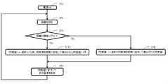
- FIG. 3is a flowchart showing the operation of the electronic apparatus including the display control apparatus according to Embodiment 1 of the present invention.
- Step ST1the proximity object measuring unit 10 measures the distance between an object such as a hand around the display screen 5a and the display screen 5a, and the process proceeds to step ST3.
- step ST3when the distance determination unit 11 determines that the distance measured in step ST2 is not equal to or less than a predetermined threshold, the illuminance value acquisition method determination unit 12 uses the first acquisition method as an illuminance value acquisition method. Is applied and the process proceeds to step ST4. Similarly, when the distance determination unit 11 determines that the distance measured in step ST2 is equal to or less than a predetermined threshold, the illuminance value acquisition method determination unit 12 uses the second acquisition method as an illuminance value acquisition method. Is applied and the process proceeds to step ST5.
- step ST4the illuminance value acquisition unit 13 acquires the illuminance value calculated by the illuminance value calculation unit 15, and proceeds to step ST6.
- step ST6the illuminance value acquired in step ST4 is stored, and the process proceeds to step ST7.
- step ST5the illuminance value acquisition unit 13 acquires the illuminance value stored in step ST6, and the process proceeds to step ST7. Note that step ST6 is never performed after the power is turned on, and if step ST5 is reached, step ST4 and step ST6 are performed.
- step ST7the display image control unit 14 adjusts the luminance of the image signal input from the information device 4 based on the illuminance value acquired in step ST4 or step ST5, or changes the ⁇ value.
- the display image displayed on the display screen 5ais controlled, and the process proceeds to step ST2.
- the illuminance sensor 7enters the shadow of the object so that the illuminance Even if the illuminance of light incident on the sensor 7 decreases, the illuminance value input to the display image control unit 14 is not changed, so that the illuminance value input to the display image control unit 14 is more appropriate. Can be.
- the method for obtaining the illuminance value for the display screen 5ais determined according to the presence or absence of a proximity object to the display screen 5a, and based on the obtained illuminance value. By controlling the display image on the display screen 5a, it is possible to reduce an uncomfortable feeling when the user is viewing the display screen 5a.
- the proximity object measuring unit 10, the illuminance value calculating unit 15, the information device 4, and the display 5have the same configuration as that of the existing electronic device, and the distance determining unit 11, the illuminance value acquiring method determining unit 12, and the illuminance value acquiring unit. 13 and the display image control unit 14 are configured by the CPU 2 and the memory 3, so that they can operate by downloading a program to the existing display control board 1, and can be configured by existing electronic devices as a whole. Has an effect.
- FIG. A display control apparatusaccording to Embodiment 2 of the present invention will be described with reference to FIG.
- the same reference numerals as those in FIG. 3denote the same or corresponding parts.
- the illuminance value input to the display image control unit 14is changed if the illuminance sensor 7 is close enough to enter the shadow of the object.
- the vehicleenters the tunnel at that timing, it is necessary to change the brightness of the display image on the display screen 5a in accordance with the significant decrease in the illuminance of the light incident on the display screen 5a. Nevertheless, the display image remains as it is, and the user feels uncomfortable (particularly during the day). Therefore, in the second embodiment, as a second acquisition method for acquiring the illuminance value, the illuminance value is acquired with higher illuminance measurement sensitivity than the first acquisition method.
- operations different from those of the first embodimentwill be described.
- FIG. 4is a flowchart showing the operation of the electronic apparatus including the display control apparatus according to Embodiment 2 of the present invention.
- the method for acquiring the illuminance valueis different from that in the first embodiment, and specifically, the operation in step ST9 is different.
- expression different from step ST4 of the first embodimentis used for step ST8, but the operation content is the same, and the illuminance measurement sensitivity in the first acquisition method is defined as normal illuminance measurement sensitivity.
- step ST3when the illuminance value acquisition method determination unit 12 determines to apply the second acquisition method as the illuminance value acquisition method, the process proceeds to step ST9.
- step ST9the illuminance measurement sensitivity is set higher than usual.
- the illuminance value calculated by the illuminance value calculation unit 15 and input to the illuminance value acquisition unit 13is calculated by setting the normal illuminance measurement sensitivity a1
- the illuminance value acquisition unit 13If the acquisition method input from the value acquisition method determination unit 12 is the second acquisition method, the illuminance value input from the illuminance value calculation unit 15 is divided by a1 and multiplied by a2, The illuminance value is obtained by artificially increasing the illuminance measurement sensitivity.
- the illuminance value acquisition unit 13may be configured by a CPU mounted on the illuminance sensor 7, and the illuminance value may be acquired by artificially increasing the illuminance measurement sensitivity in the same manner as described above.
- the illuminance sensoris capable of setting and changing the illuminance measurement sensitivity of the illuminance value calculation unit 15, the illuminance value acquisition unit 13 of the illuminance value calculation unit 15 according to the acquisition method input from the illuminance value acquisition method determination unit 12
- the illuminance value calculation unit 15may be instructed to set the illuminance measurement sensitivity.
- the illuminance sensor 7when an object such as a hand is brought close to the display screen 5a, the illuminance sensor 7 enters the shadow of the object so that the illuminance Even if the illuminance of the light incident on the sensor 7 decreases, the illuminance value input to the display image control unit 14 can be suppressed from decreasing by increasing the illuminance measurement sensitivity. Therefore, the illuminance value corresponding to the illuminance incident on the display screen 5a can be acquired.
- the display control apparatus shown in Embodiment 2it has the same effect as the display control apparatus in Embodiment 1, and the user feels more uncomfortable when viewing the display screen 5a. It has the effect that it can reduce.
- Modification 1 of Embodiment 2A display control apparatus according to Modification 1 of Embodiment 2 of the present invention will be described with reference to FIG. 5, the same reference numerals as those in FIG. 4 denote the same or corresponding parts.
- the illuminance valueis acquired with a higher illuminance measurement sensitivity than in the first acquisition method, whereas the first modification of the second embodiment is used.
- a value obtained by adding an offset, which is a correction value, to the illuminance value calculated with the same illuminance measurement sensitivity as in the first acquisition methodis acquired as the illuminance value.
- an offsetwhich is a correction value
- FIG. 5is a flowchart showing the operation of the electronic apparatus including the display control device in the first modification of the second embodiment of the present invention.
- the second method for obtaining the illuminance valueis different from that in the second embodiment, and specifically, the operation in step ST10 is different.
- step ST3when the illuminance value acquisition method determination unit 12 determines to apply the second acquisition method as the illuminance value acquisition method, the process proceeds to step ST10.
- the illuminance value acquisition unit 13inputs from the illuminance value acquisition method determination unit 12. If the acquisition method is the second acquisition method, an illuminance value obtained by adding ⁇ to the illuminance value input from the illuminance value calculation unit 15 is acquired.
- the illuminance value acquisition unit 13may be configured by a CPU mounted on the illuminance sensor 7, and an illuminance value may be acquired by adding an offset in the same manner as described above.
- the illuminance value calculation unit 15is an illuminance sensor in which the presence / absence of offset addition can be set and changed
- the illuminance value acquisition unit 13performs the illuminance value calculation unit 15 according to the acquisition method input from the illuminance value acquisition method determination unit 12.
- the illuminance value calculation unit 15may be instructed to set whether or not to add an offset.
- the display control apparatus shown in the first modification of the second embodimentwhen an object such as a hand is brought close to the display screen 5a, the illuminance sensor 7 appears in the shadow of the object. Even if the illuminance of the light incident on the illuminance sensor 7 is reduced by entering, the reduction of the illuminance value input to the display image control unit 14 can be suppressed by adding an offset. Therefore, the illuminance value corresponding to the illuminance incident on the display screen 5a can be acquired.
- the display control device shown in the first modification of the second embodimenthas the same effect as the display control device in the first embodiment, and the user is viewing the display screen 5a. There is an effect that the sense of incongruity can be further reduced.
- Modification 2 of Embodiment 2A display control apparatus in Modification 2 of Embodiment 2 of the present invention will be described with reference to FIG. 6, the same reference numerals as those in FIG. 4 or 5 indicate the same or corresponding parts.
- the illuminance valueis acquired with a higher illuminance measurement sensitivity than in the first acquisition method
- the first modification of the second embodimentthe first Whereas the value obtained by adding an offset to the illuminance value calculated with the same illuminance measurement sensitivity as that of the acquisition method is acquired as the illuminance value
- the second modification of the second embodimentis more effective than the first acquisition method.
- a value obtained by adding an offset to the illuminance value calculated by increasing the illuminance measurement sensitivityis acquired as the illuminance value. That is, the second acquisition method of the second embodiment and the first modification of the second embodiment is applied. Hereinafter, operations different from those of the second embodiment will be described.
- FIG. 6is a flowchart showing the operation of the electronic apparatus including the display control device in the second modification of the second embodiment of the present invention.
- the second method for obtaining the illuminance valueis different from that in the second embodiment, and specifically, the operation in step ST11 is different.
- step ST3when the illuminance value acquisition method determination unit 12 determines to apply the second acquisition method as the illuminance value acquisition method, the process proceeds to step ST11.
- step ST11the illuminance measurement sensitivity is set higher than usual. Then, a value obtained by adding an offset to the calculated illuminance value is acquired, and the process proceeds to step ST7. That is, in step ST8, the illuminance value calculated by equation (1) is acquired, but in step ST11, the illuminance value calculated by equation (6) is acquired.
- the illuminance value calculated by the illuminance value calculation unit 15 and input to the illuminance value acquisition unit 13is calculated by setting the normal illuminance measurement sensitivity a1, the illuminance value acquisition unit 13 If the acquisition method input from the value acquisition method determination unit 12 is the second acquisition method, the illuminance value input from the illuminance value calculation unit 15 is divided by a1 and multiplied by a2, and then ⁇ Get the added illuminance value.
- the illuminance value acquisition unit 13is configured by a CPU mounted on the illuminance sensor 7, and the illuminance value is acquired by artificially increasing the illuminance measurement sensitivity in the same manner as described above. May be obtained.
- the illuminance value acquisition unit 13determines the illuminance according to the acquisition method input from the illuminance value acquisition method determination unit 12
- the illuminance value calculation unit 15may be instructed to set the illuminance measurement sensitivity of the value calculation unit 15 and whether to add an offset.
- the illuminance sensor 7when an object such as a hand is brought close to the display screen 5a, the illuminance sensor 7 becomes a shadow of the object. Even if the illuminance of light incident on the illuminance sensor 7 is reduced by entering, the illuminance measurement sensitivity is made higher than usual, and an offset is added to reduce the illuminance value input to the display image control unit 14. Can be suppressed. Therefore, the illuminance value corresponding to the illuminance incident on the display screen 5a can be acquired. As a result, the display control device shown in the second modification of the second embodiment has the same effect as the display control device in the first embodiment, and the user is viewing the display screen 5a. There is an effect that the sense of incongruity can be further reduced.
- FIG. 3A display control apparatus according to Embodiment 3 of the present invention will be described with reference to FIGS. 2, 4, 5, 6, and 7.
- FIG. 2when an object such as a hand is brought close to the display screen 5a, the illuminance value input to the display image control unit 14 by the illuminance sensor 7 entering the shadow of the object is As a result, the display image on the display screen 5a is changed. That is, it is possible to reduce discomfort when the user is viewing the display screen 5a, but it may not be sufficient.
- the display image control unit 14uses the determination result by the distance determination unit 11 to reduce the above-mentioned uncomfortable feeling. Change the control method of the image signal. That is, in FIG. 4, FIG. 5 or FIG. 6, which is a flowchart showing the operation of the display control apparatus in the second embodiment (including the modification), the operation of step ST7 is different. Hereinafter, operations different from those of the second embodiment will be described.
- the block diagram of the electronic device including the display control device in the third embodimentis similar to the block diagram in the first embodiment shown in FIG. 2 (the block diagram in the second embodiment is also a block diagram in the first embodiment).
- the determination result of the distance determination unit 11is input to the display image control unit 14 via the illuminance value acquisition method determination unit 12 and the illuminance value acquisition unit 13, and the display image control unit 14
- the image signal input from the information device 4is controlled according to the determination result of the distance determination unit 11 input from 13 and output to the display 5.
- the display image control unit 14includes a memory 3 in addition to the CPU 2 of the display control board 1.
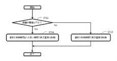
- FIG. 7is a flowchart showing a characteristic operation of the electronic apparatus including the display control device according to Embodiment 3 of the present invention.
- the operation of the display control apparatus in the third embodimentis the same as that in the second embodiment (including the modification) up to the step of obtaining the illuminance value, and the operation in step ST7 is shown in FIG.
- step ST12the display image control unit 14 operates according to the determination result in the distance determination unit 11 input from the illuminance value acquisition unit 13. That is, if it is a determination result that the measurement distance is not less than or equal to a predetermined threshold, the process proceeds to step ST13, and if it is a determination result that the measurement distance is less than or equal to a predetermined threshold, the process proceeds to step ST14.
- step ST13the display image control unit 14 adjusts the luminance of the image signal input from the information device 4 based on the illuminance value acquired in step ST8, changes the ⁇ value, or the like.
- the image signal of the display image displayed on the screenis determined (hereinafter, the determined display image is referred to as “determined display image 1”), and the display image displayed on the display screen 5a is determined and displayed in a predetermined t1 second. Transition to the image 1 and proceed to step ST2.
- the time for controlling the display image on the display screen 5a in this stepis defined as a normal control time.
- step ST14the display image control unit 14 adjusts the luminance of the image signal input from the information device 4 based on the illuminance value acquired in step ST9, step ST10, or step ST11, or changes the ⁇ value.
- the determined display imageis referred to as “determination display image 2”
- the display image to be transferredis changed to the determined display image 2, and the process proceeds to step ST2.
- t1 and t2are stored in the memory 3 and have a relationship of t1 ⁇ t2.
- step ST13 and step ST14the screen transition times are fixed at t1 and t2, respectively.
- the screen transition timesmay be constant speed transitions and may transition at constant speeds v1 and v2, respectively.
- v1 and v2are stored in the memory 3 and have a relationship of v1> v2.
- step ST13 and step ST14the screen transition times are fixed at t1 and t2, respectively.
- the screen transition speedis not a constant speed and may be decelerated near the completion of the screen transition. Thereby, the uncomfortable feeling at the time of the user visually recognizing the display screen 5a can be reduced more.
- the display control device shown in the third embodimenthas the same effect as the display control device in the second embodiment (including the modified example).
- the illuminance value input to the display image control unit 14is changed by the illuminance sensor 7 entering the shadow of the object, thereby displaying the display screen 5a.
- the usermay feel uncomfortable, but the effect that the discomfort can be further reduced by lengthening the transition time of the display image. Have.
- the display control device, the mobile object display device, and the display control method of the present inventionhave been described in the vehicle-mounted device, but the present invention is not limited to this, and the device mounted on the mobile object such as an aircraft or a train. May be used.
- the configuration of each unitmay be replaced with an arbitrary configuration having the same function.
- the proximity sensor 6may be replaced by image recognition by a camera.
- 1 Display control board2 CPU, 3 Memory, 4 Information device, 5 Display, 5a Display screen, 6 Proximity sensor, 7 Illuminance sensor, 8 Handle, 9 Dashboard, 10 Proximity measurement unit, 11 Distance determination unit, 12 Illuminance Value acquisition method determination unit, 13 illuminance value acquisition unit, 14 display image control unit, 15 illuminance value calculation unit, 16 hands.
Landscapes
- Engineering & Computer Science (AREA)
- Theoretical Computer Science (AREA)
- Physics & Mathematics (AREA)
- General Physics & Mathematics (AREA)
- Computer Hardware Design (AREA)
- Transportation (AREA)
- Chemical & Material Sciences (AREA)
- Combustion & Propulsion (AREA)
- Mechanical Engineering (AREA)
- General Engineering & Computer Science (AREA)
- Human Computer Interaction (AREA)
- Controls And Circuits For Display Device (AREA)
- Instrument Panels (AREA)
- Fittings On The Vehicle Exterior For Carrying Loads, And Devices For Holding Or Mounting Articles (AREA)
Abstract
Description
Translated fromJapanese本発明は、例えば、車両に搭載されるディスプレイ制御装置、移動体表示装置及びディスプレイ制御方法に係り、ディスプレイ画面への照度及びディスプレイ画面に対する近接物の有無に応じてディスプレイ画面の表示画像を制御する技術に関する。The present invention relates to, for example, a display control device mounted on a vehicle, a moving body display device, and a display control method, and controls a display image on a display screen according to the illuminance on the display screen and the presence or absence of a proximity object to the display screen. Regarding technology.
カーナビゲーション装置等のディスプレイ画面に入射している光の照度から照度値を取得する照度センサーを備え(精度を高めるため、通常、ディスプレイ画面近傍に備えられる)、取得された照度値に応じてディスプレイ画面の表示画像を制御するものがある。例えば、晴天の日中のように太陽光が車内に差し込む状況においてはディスプレイ画面への照度が高くなる(照度値が高くなる)ことからディスプレイ画面の表示画像を明るくし(例えば、輝度を高くする)、夜間のように太陽光が車内に差し込まない状況においてはディスプレイ画面への照度が低くなる(照度値が低くなる)ことからディスプレイ画面の表示画像を暗くする(例えば、輝度を低くする)ことで、ユーザーによるディスプレイ画面の視認性を向上させている。Equipped with an illuminance sensor that acquires the illuminance value from the illuminance of the light incident on the display screen of a car navigation device or the like (usually provided near the display screen to improve accuracy), and displays depending on the acquired illuminance value Some control the display image on the screen. For example, in a situation where sunlight is inserted into the vehicle, such as during sunny days, the illuminance on the display screen increases (the illuminance value increases), so the display image on the display screen is brightened (for example, the luminance is increased). ) In the situation where sunlight is not inserted into the car, such as at night, the illuminance on the display screen will be low (the illuminance value will be low), so the display image on the display screen will be darkened (for example, the luminance will be low). Therefore, the visibility of the display screen by the user is improved.
また、ディスプレイ画面に対する近接物の有無を検出する近接センサーを更に備え、照度センサーにより取得された照度値及び近接センサーによる検出結果に応じてディスプレイ画面の表示画像を制御する車両用入力装置が提案されている(特許文献1参照)。具体的には、照度センサーにより日中である(照度値が高い)と判断された場合、近接センサーにより手が接近したと判断されるとディスプレイ画面にタッチ操作用の入力部を表示させ、手が離れてから所定時間が経過するとタッチ操作用の入力部を消滅させる。また、照度センサーにより夜間である(照度値が低い)と判断された場合、近接センサーにより手が接近していないと判断されるとタッチ操作用の入力部を薄っすらと表示し、手が接近していると判断されるとタッチ操作用の入力部を濃く表示することで、ユーザーの操作性(視認性)を向上させている。In addition, a vehicle input device that further includes a proximity sensor that detects the presence or absence of a proximity object with respect to the display screen and controls the display image on the display screen according to the illuminance value acquired by the illuminance sensor and the detection result by the proximity sensor has been proposed. (See Patent Document 1). Specifically, when it is determined by the illuminance sensor that it is daytime (the illuminance value is high), if the proximity sensor determines that the hand is approaching, an input unit for touch operation is displayed on the display screen, and the hand When a predetermined time elapses after the button is released, the input unit for touch operation disappears. Also, if it is determined by the illuminance sensor that it is night (the illuminance value is low), if the proximity sensor determines that the hand is not approaching, the touch operation input unit is displayed thinly, When it is determined that the user is approaching, the operability (visibility) of the user is improved by displaying the input portion for touch operation darkly.
上記した従来のディスプレイ画面を備えたカーナビゲーション装置等(ディスプレイ制御装置)では、ディスプレイ画面上や周辺に配置された入力部を操作しようと手を近づけた際に手の影により照度センサーへの照度が低下し、ディスプレイ画面への照度には変化がないためディスプレイ画面の表示画像を変更する(例えば、暗くする)必要がないにもかかわらずディスプレイ画面の表示画像を変更してしまい(例えば、暗くしてしまう)、ユーザーに違和感を与えてしまうという問題があった。In a car navigation device or the like (display control device) equipped with a conventional display screen as described above, the illuminance to the illuminance sensor due to the shadow of the hand when the user approaches the input unit arranged on or around the display screen. The display image on the display screen is changed (for example, darkened) even though there is no need to change (for example, darken) the display image on the display screen because there is no change in the illuminance on the display screen. There was a problem that it felt uncomfortable for the user.
同様に、上記した照度センサー及び近接センサーを備える車両用入力装置(ディスプレイ制御装置)では、日中において、ディスプレイ画面上に配置されたタッチ操作用の入力部を操作しようと手を近づけた際に手の影により照度センサーへの照度が低下し、ディスプレイ画面への照度には変化がないにもかかわらず、タッチ操作用の入力部が非表示から薄っすらとした表示に変わり、一連の動作で更に手を近づけることによりタッチ操作用の入力部が薄っすらとした表示から濃い表示へと変わり、ユーザーがディスプレイ画面を視認している際に違和感を与えてしまうという問題があった。Similarly, in the vehicle input device (display control device) including the illuminance sensor and the proximity sensor described above, when a hand is brought close to operate the input unit for touch operation arranged on the display screen during the daytime. Even though the illuminance to the illuminance sensor decreases due to the shadow of the hand and the illuminance to the display screen does not change, the input section for touch operation changes from non-display to a thin display, and a series of operations In this case, the input part for touch operation is changed from a thin display to a dark display by bringing the hand closer, and there is a problem that the user feels uncomfortable when viewing the display screen.
本発明は上記した問題点を解決するためになされたものであり、ディスプレイ画面に対する近接物の有無に応じてディスプレイ画面に対する照度値の取得方法を決定し、取得された照度値に基づいてディスプレイ画面の表示画像を制御することで、ユーザーがディスプレイ画面を視認している際の違和感を低減することが可能なディスプレイ制御装置、移動体表示装置及びディスプレイ制御方法を提供することを目的とする。The present invention has been made to solve the above-described problems, and determines a method for obtaining an illuminance value for a display screen according to the presence or absence of a proximity object with respect to the display screen, and the display screen is based on the obtained illuminance value. It is an object of the present invention to provide a display control device, a mobile display device, and a display control method capable of reducing a sense of incongruity when a user is viewing a display screen by controlling the display image.
本発明に係るディスプレイ制御装置は、ディスプレイ画面の照度値を取得する照度値取得部と、照度値取得部により取得された照度値に基づき、ディスプレイ画面の表示画像を制御する表示画像制御部と、ディスプレイ画面周辺に存在する物体とディスプレイ画面との距離を測定する近接物測定部により測定された距離が予め定められた閾値以下か否かを判断する距離判断部と、距離が閾値以下でないと距離判断部が判断した場合、照度値の第一の取得方法を照度値取得部に適用させ、距離が閾値以下であると距離判断部が判断した場合、照度値の第二の取得方法を照度値取得部に適用させる照度値取得方法決定部とを備える。The display control apparatus according to the present invention includes an illuminance value acquisition unit that acquires an illuminance value of a display screen, a display image control unit that controls a display image of the display screen based on the illuminance value acquired by the illuminance value acquisition unit, A distance determination unit that determines whether or not the distance measured by the proximity object measurement unit that measures the distance between an object existing around the display screen and the display screen is equal to or less than a predetermined threshold, and a distance that is not equal to or less than the threshold When the determination unit determines, the first acquisition method of the illuminance value is applied to the illuminance value acquisition unit, and when the distance determination unit determines that the distance is equal to or less than the threshold value, the second acquisition method of the illuminance value is changed to the illuminance value. And an illuminance value acquisition method determination unit to be applied to the acquisition unit.
上記のように構成されたディスプレイ制御装置は、ディスプレイ画面に対する近接物の有無に応じてディスプレイ画面に対する照度値の取得方法を決定し、取得された照度値に基づいてディスプレイ画面の表示画像を制御することで、ユーザーがディスプレイ画面を視認している際の違和感を低減することができるという効果を有する。The display control device configured as described above determines an illuminance value acquisition method for the display screen according to the presence or absence of a proximity object to the display screen, and controls the display image on the display screen based on the acquired illuminance value. Thus, it is possible to reduce an uncomfortable feeling when the user is viewing the display screen.
以下、本発明の実施の形態について図面を参照しつつ説明する。Hereinafter, embodiments of the present invention will be described with reference to the drawings.
実施の形態1.
本発明の実施の形態1におけるディスプレイ制御装置について図1、図2及び図3を用いて説明する。
図1は本発明の実施の形態1におけるディスプレイ制御装置を含む電子機器のH/W構成例であり、図1(a)は車両の座席側からダッシュボード方向を見た概略図、図1(b)はディスプレイ5、近接センサー6及び照度センサー7を図1(a)のA方向から見た概略図、図1(c)は各H/Wの接続関係を示す図である。
図1(a)を用いて、実施の形態1におけるディスプレイ制御装置を含む電子機器の配置について説明する。ダッシュボード9に情報機器4、ディスプレイ5、ディスプレイ制御基板1(図示せず)、近接センサー6及び照度センサー7が配置されるが、配置位置はこれに限らず、例えば、情報機器4とディスプレイ5が一体化されていてもよく、更に、タッチパネル式ディスプレイを用いることで情報機器4の操作ボタン(ハードウェアボタン)をディスプレイ5のディスプレイ画面5a上に配してもよい(ソフトウェアボタン)。また、情報機器4は、車載機器に限らず、携帯電話等の移動体端末であり、USBケーブルといった有線でディスプレイ制御基板1と接続させてもよく、Bluetooth(登録商標)といった無線でディスプレイ制御基板1と接続させてもよい。
A display control apparatus according to
FIG. 1 is an example of an H / W configuration of an electronic device including a display control device according to
With reference to FIG. 1A, an arrangement of electronic devices including the display control device in
図1(c)を用いて、実施の形態1におけるディスプレイ制御装置を含む電子機器の動作について説明する。
近接センサー6は、ディスプレイ画面5aの周辺に存在する物体とディスプレイ画面5aとの距離(以後、「測定距離」という)を測定し、ディスプレイ制御基板1へ出力する。ここで、測定距離は、図1(b)の例では、手16とディスプレイ画面5aとの距離Dとなる。
照度センサー7は、ディスプレイ画面5aに入射される光の照度に対する照度値を算出することを目的としており、ディスプレイ画面5aの近くに配置されることが好ましく、照度センサー7に入射される光の照度から照度値を算出し、ディスプレイ制御基板1へ出力する。例えば、照度センサー7に入射される光の照度をx、照度センサー7の照度測定感度をa1(例えば、a1=1.0)とすると、照度センサー7により算出される照度値y1は式(1)となるが、これに限らず、式(2)又は式(3)といった関係であってもよい。尚、式(2)におけるa1(x)はxの関数であることを意味している。以後、式(1)を用いた場合として説明する。The operation of the electronic device including the display control device in
The
The
(数1)
y1=a1・x …式(1)(Equation 1)
y1 = a1 · x (1)
(数2)
y1=a1(x)・x …式(2)(Equation 2)
y1 = a1 (x) · x (2)
(数3)
y1=a1・x・x …式(3)(Equation 3)
y1 = a1 · x · x (3)
ディスプレイ制御基板1は、CPU2及びメモリ3により構成され、取得した照度値に基づいて、情報機器4から入力された画像信号の輝度を調整してディスプレイ5へ出力する。例えば、ディスプレイ画面5aに表示されている表示画像に対するユーザーの視認性が高くなるように、取得した照度値が高い場合は画像信号の輝度を高くし、取得した照度値が低い場合は画像信号の輝度を低くする。尚、上述では、画像信号の輝度を調整するとしたが、γ値を変更する等により画像信号を変更するようにしてもよい。The
ディスプレイ5は、ディスプレイ制御基板1から入力された画像信号をディスプレイ画面5aに表示する。The
ここで、ユーザーがディスプレイ画面5a上の操作ボタンを操作しようと手等を近づけることで照度センサー7が手等の影に入ってしまうと、照度センサー7はディスプレイ画面5aに入射されている光の照度に対する照度値よりも低い値を算出してしまい、この照度値に基づいてディスプレイ画面5aに表示する画像信号を制御すると、ディスプレイ画面5aの表示画像を変更する(例えば、輝度を低くする)必要がないにもかかわらず、表示画像を変更してしまい(例えば、輝度を低くしてしまう)、ユーザーがディスプレイ画面5aを視認している際に違和感を与えてしまう。これに対して、本実施の形態1におけるディスプレイ制御装置では、近接センサー6で測定した測定距離に応じて照度値の取得方法を決定することでユーザーがディスプレイ画面5aを視認している際の違和感を低減する。照度値の取得方法については、図2及び図3の説明において詳述する。Here, if the
図2は本発明の実施の形態1におけるディスプレイ制御装置を含む電子機器のブロック図である。
近接物測定部10は、近接センサー6により構成される。近接センサー6は、ディスプレイ画面5aの周辺に存在する物体とディスプレイ画面5aとの距離を測定し、距離判断部11へ出力する。尚、近接センサー6の測定範囲内に物体が存在しない場合は、ヌル値といった予め定めた値を出力する。以後、ヌル値を出力するものとして説明する。FIG. 2 is a block diagram of an electronic apparatus including the display control device according to
The proximity
距離判断部11は、ディスプレイ制御基板1のCPU2及びメモリ3により構成される。CPU2は、近接物測定部10から入力された測定距離とメモリ3に記憶されている閾値とを比較し、測定距離が閾値以下であるか否かを判断し、照度値取得方法決定部12へ出力する。ここで、測定距離がヌル値の場合は、測定距離が閾値以下でないと判断する。
尚、手等の物体をディスプレイ画面5aに近づけた際に、照度センサー7が当該物体の影に入るようになる当該物体とディスプレイ画面5aとの距離を閾値として設定しておくとよい。また、メモリ3に記憶する閾値は、ユーザーの好みにより変更できるようにしてもよい。
ここで、近接センサー6として、例えば、放射した赤外線が物体に反射して受光されるまでの時間から物体との距離を算出する赤外線センサーもあれば、放射した赤外線が物体に反射して受光された光量から近接物の有無を判断する赤外線センサーもある。後者の赤外線センサーの場合も、近接物が予め定められた距離内に存在するかを判断するにあたり受光された光量から物体との距離を算出していることになる。The
In addition, when an object such as a hand is brought close to the
Here, as the
照度値取得方法決定部12は、ディスプレイ制御基板1のCPU2により構成される。CPU2は、距離判断部11から入力された判断結果に応じて照度値の取得方法を決定し、照度値取得部13へ出力する。つまり、測定距離が閾値以下でないとの判断結果の場合は第一の取得方法とし、測定距離が閾値以下であるとの判断結果の場合は第二の取得方法とする。The illuminance value acquisition
照度値算出部15は、照度センサー7により構成される。照度センサー7は、照度センサー7に入射される光の照度から照度値を算出し、照度値取得部13へ出力する。The illuminance
照度値取得部13は、ディスプレイ制御基板1のCPU2及びメモリ3により構成される。CPU2は、照度値取得方法決定部12から入力された取得方法が第一の取得方法であれば、照度値算出部15から入力された照度値を表示画像制御部14へ出力するとともにメモリ3に記憶させる。また、CPU2は、照度値取得方法決定部12から入力された取得方法が第二の取得方法であれば、メモリ3に記憶された照度値を表示画像制御部14へ出力する。但し、ディスプレイ制御装置の電源投入直後のようにメモリ3に照度値が記憶されていない場合は、第一の取得方法を適用すればよいが、これに限らない。例えば、予め定められた値を表示画像制御部14へ出力するとともにメモリ3に記憶させてもよい。The illuminance
表示画像制御部14は、ディスプレイ制御基板1のCPU2により構成される。CPU2は、照度値取得部13から入力された照度値に基づいて、情報機器4から入力された画像信号の輝度を調整したり、γ値を変更したりして、ディスプレイ5へ出力する。The display
ディスプレイ制御装置は、距離判断部11、照度値取得方法決定部12、照度値取得部13及び表示画像制御部14により構成される。従って、上記の構成においては、ディスプレイ制御装置は、ディスプレイ制御基板1により構成されることになる。The display control device includes a
尚、各ブロックは、同様の機能を有すれば上記の構成に限るものではなく、例えば、距離判断部11が、近接センサー6に搭載されたCPU及びメモリにより構成されてもよいし、照度値取得部13が、照度センサー7に搭載されたCPU及びメモリにより構成されてもよい。この場合、ディスプレイ制御装置は、ディスプレイ制御基板1と近接センサー6又は照度センサー7の少なくとも1つにより構成されることになる。Each block is not limited to the above configuration as long as it has a similar function. For example, the
また、移動体表示装置は、ディスプレイ制御装置及びディスプレイ5により構成される。これは、本発明が、移動体に搭載された表示装置の表示画面(ディスプレイ画面5a)を視認している際に生じる違和感を低減するものであって、ディスプレイ制御装置により表示画面へ表示する画像を制御した上で表示画面に表示させるものであることによる。尚、移動体表示装置は、ディスプレイ制御装置とディスプレイ5が別体になっていても一体になっていても同様の機能を有すれば、任意の構成をとることができる。The mobile display device is composed of a display control device and a
次に、フローチャートを用いて本実施の形態1におけるディスプレイ制御装置の動作について詳しく説明する。図3は本発明の実施の形態1におけるディスプレイ制御装置を含む電子機器の動作を示すフローチャートである。Next, the operation of the display control apparatus according to the first embodiment will be described in detail using a flowchart. FIG. 3 is a flowchart showing the operation of the electronic apparatus including the display control apparatus according to
ディスプレイ制御装置の電源がON状態になると動作を開始する。(ステップST1)
ステップST2では、近接物測定部10により、ディスプレイ画面5aの周辺に存在する手等の物体とディスプレイ画面5aとの距離を測定し、ステップST3へ進む。The operation starts when the power of the display control device is turned on. (Step ST1)
In step ST2, the proximity
ステップST3では、距離判断部11により、ステップST2で測定した距離が予め定められた閾値以下でないと判断されると、照度値取得方法決定部12により、照度値の取得方法として第一の取得方法を適用すると決定され、ステップST4へ進む。同様に、距離判断部11により、ステップST2で測定した距離が予め定められた閾値以下であると判断されると、照度値取得方法決定部12により、照度値の取得方法として第二の取得方法を適用すると決定され、ステップST5へ進む。In step ST3, when the
ステップST4では、照度値取得部13が、照度値算出部15により算出された照度値を取得し、ステップST6へ進む。
ステップST6では、ステップST4で取得された照度値を記憶し、ステップST7へ進む。
ステップST5では、照度値取得部13が、ステップST6にて記憶した照度値を取得し、ステップST7へ進む。尚、電源がON状態になってからステップST6が一度も実施されず、ステップST5に到達した場合は、ステップST4及びステップST6を実施するものとする。In step ST4, the illuminance
In step ST6, the illuminance value acquired in step ST4 is stored, and the process proceeds to step ST7.
In step ST5, the illuminance
ステップST7では、表示画像制御部14が、ステップST4又はステップST5において取得された照度値に基づいて情報機器4から入力された画像信号の輝度を調整したり、γ値を変更したりする等によりディスプレイ画面5aに表示される表示画像を制御し、ステップST2へ進む。In step ST7, the display
以上述べたように、この実施の形態1にて示したディスプレイ制御装置にあっては、手等の物体をディスプレイ画面5aに近づけた際に、照度センサー7が当該物体の影に入ることで照度センサー7に入射される光の照度が下がっても、表示画像制御部14へ入力される照度値が変更されないようにすることで、表示画像制御部14に入力される照度値をより適切なものにすることができる。
つまり、この実施の形態1にて示したディスプレイ制御装置にあっては、ディスプレイ画面5aに対する近接物の有無に応じてディスプレイ画面5aに対する照度値の取得方法を決定し、取得された照度値に基づいてディスプレイ画面5aの表示画像を制御することで、ユーザーがディスプレイ画面5aを視認している際の違和感を低減することができるという効果を有する。As described above, in the display control apparatus shown in the first embodiment, when an object such as a hand is brought close to the
In other words, in the display control apparatus shown in the first embodiment, the method for obtaining the illuminance value for the
また、近接物測定部10、照度値算出部15、情報機器4及びディスプレイ5は、既存の電子機器と同様の構成であり、距離判断部11、照度値取得方法決定部12、照度値取得部13及び表示画像制御部14は、CPU2及びメモリ3から構成されることから既存のディスプレイ制御基板1にプログラムをダウンロードさせることで動作可能であり、全体として既存の電子機器で構成することができるという効果を有する。Further, the proximity
実施の形態2.
本発明の実施の形態2におけるディスプレイ制御装置について図4を用いて説明する。尚、図4において、図3と同一符号は同一又は相当部分を示す。実施の形態1では、手等の物体をディスプレイ画面5aに近づけた際に、照度センサー7が当該物体による影に入る程度に近づいていると、表示画像制御部14に入力される照度値が変更されないようにするが、そのタイミングで車両がトンネル内に入ると、ディスプレイ画面5aに入射される光の照度が大きく低下するのに合わせてディスプレイ画面5aの表示画像の輝度等を変更する必要があるにもかかわらず、表示画像がそのままとなりユーザーに違和感を与えてしまう(特に、日中)。そこで、実施の形態2では、照度値を取得する第二の取得方法として、第一の取得方法よりも照度測定感度を高くして照度値を取得する。以下、実施の形態1と異なる動作について説明する。
A display control apparatus according to
図4は本発明の実施の形態2におけるディスプレイ制御装置を含む電子機器の動作を示すフローチャートである。上述したように、照度値の取得方法が実施の形態1と異なり、具体的にはステップST9の動作が異なる。ステップST8については、便宜上、実施の形態1のステップST4とは異なる表現を用いているが、動作内容は同一であり、第一の取得方法における照度測定感度を通常の照度測定感度と定義する。FIG. 4 is a flowchart showing the operation of the electronic apparatus including the display control apparatus according to
ステップST3において、照度値取得方法決定部12により、照度値の取得方法として第二の取得方法を適用すると決定されるとステップST9へ進むが、ステップST9では、通常よりも高い照度測定感度に設定して算出された照度値を取得し、ステップST7へ進む。つまり、ステップST8では、式(1)により算出された照度値を取得するが、ステップST9では、照度測定感度を通常のa1よりも高いa2として式(4)により算出された照度値を取得する。(例えば、a1=1.0、a2=1.5)In step ST3, when the illuminance value acquisition
(数4)
y1=a2・x …式(4)(Equation 4)
y1 = a2 · x (4)
ここで、照度値算出部15で算出し、照度値取得部13に入力される照度値は通常の照度測定感度a1に設定して算出されたものであるので、照度値取得部13では、照度値取得方法決定部12から入力された取得方法が第二の取得方法であれば、照度値算出部15から入力された照度値に対してa1で除算し、かつ、a2で乗算することで、疑似的に照度測定感度を高めて照度値を取得する。尚、照度値取得部13を照度センサー7に搭載されたCPUにより構成されるようにし、上記と同様に疑似的に照度測定感度を高めて照度値を取得するようにしてもよい。また、照度値算出部15の照度測定感度を設定変更可能な照度センサーであれば、照度値取得部13が照度値取得方法決定部12から入力された取得方法に応じて照度値算出部15の照度測定感度を設定するよう照度値算出部15へ指示するようにしてもよい。Here, since the illuminance value calculated by the illuminance
以上述べたように、この実施の形態2にて示したディスプレイ制御装置にあっては、手等の物体をディスプレイ画面5aに近づけた際に、照度センサー7が当該物体の影に入ることで照度センサー7に入射される光の照度が下がっても、照度測定感度を通常よりも高くすることで表示画像制御部14に入力される照度値の低減を抑えることができる。従って、ディスプレイ画面5aに入射されている照度に対応した照度値を取得することができる。これにより、実施の形態2にて示したディスプレイ制御装置にあっては、実施の形態1におけるディスプレイ制御装置と同様の効果を有し、ユーザーがディスプレイ画面5aを視認している際の違和感をより低減することができるという効果を有する。As described above, in the display control apparatus shown in the second embodiment, when an object such as a hand is brought close to the
実施の形態2の変形例1.
本発明の実施の形態2の変形例1におけるディスプレイ制御装置について図5を用いて説明する。図5において、図4と同一符号は同一又は相当部分を示す。照度値を取得する第二の取得方法として、実施の形態2では、第一の取得方法よりも照度測定感度を高くして照度値を取得するのに対して、実施の形態2の変形例1では、第一の取得方法と同一の照度測定感度で算出した照度値に対して補正値であるオフセットを付加した値を照度値として取得する。以下、実施の形態2と異なる動作について説明する。
A display control apparatus according to
図5は本発明の実施の形態2の変形例1におけるディスプレイ制御装置を含む電子機器の動作を示すフローチャートである。上述したように、照度値の第二の取得方法が実施の形態2と異なり、具体的にはステップST10の動作が異なる。FIG. 5 is a flowchart showing the operation of the electronic apparatus including the display control device in the first modification of the second embodiment of the present invention. As described above, the second method for obtaining the illuminance value is different from that in the second embodiment, and specifically, the operation in step ST10 is different.
ステップST3において、照度値取得方法決定部12により、照度値の取得方法として第二の取得方法を適用すると決定されるとステップST10へ進むが、ステップST10では、通常の照度測定感度に設定して算出された照度値にオフセットであるδ(例えば、δ=1.0)を付加した値を取得し、ステップST7へ進む。つまり、ステップST8では、式(1)により算出された照度値を取得するが、ステップST10では、式(5)により算出された照度値を取得する。In step ST3, when the illuminance value acquisition
(数5)
y1=a1・x+δ …式(5)(Equation 5)
y1 = a1 · x + δ Formula (5)
ここで、照度値算出部15で算出し、照度値取得部13に入力される照度値にはオフセットは付加されていないので、照度値取得部13では、照度値取得方法決定部12から入力された取得方法が第二の取得方法であれば、照度値算出部15から入力された照度値に対してδを加算した照度値を取得する。尚、照度値取得部13を照度センサー7に搭載されたCPUにより構成されるようにし、上記と同様にオフセットを付加して照度値を取得するようにしてもよい。また、照度値算出部15においてオフセット付加の有無を設定変更可能な照度センサーであれば、照度値取得部13が照度値取得方法決定部12から入力された取得方法に応じて照度値算出部15においてオフセット付加するか否かを設定するよう照度値算出部15へ指示するようにしてもよい。Here, since the illuminance value calculated by the illuminance
以上述べたように、この実施の形態2の変形例1にて示したディスプレイ制御装置にあっては、手等の物体をディスプレイ画面5aに近づけた際に、照度センサー7が当該物体の影に入ることで照度センサー7に入射される光の照度が下がっても、オフセットを付加することで表示画像制御部14に入力される照度値の低減を抑えることができる。従って、ディスプレイ画面5aに入射されている照度に対応した照度値を取得することができる。これにより、実施の形態2の変形例1にて示したディスプレイ制御装置にあっては、実施の形態1におけるディスプレイ制御装置と同様の効果を有し、ユーザーがディスプレイ画面5aを視認している際の違和感をより低減することができるという効果を有する。As described above, in the display control apparatus shown in the first modification of the second embodiment, when an object such as a hand is brought close to the
実施の形態2の変形例2.
本発明の実施の形態2の変形例2におけるディスプレイ制御装置について図6を用いて説明する。図6において、図4又は図5と同一符号は同一又は相当部分を示す。照度値を取得する第二の取得方法として、実施の形態2では、第一の取得方法よりも照度測定感度を高くして照度値を取得し、実施の形態2の変形例1では、第一の取得方法と同一の照度測定感度で算出した照度値に対してオフセットを付加した値を照度値として取得するのに対して、実施の形態2の変形例2では、第一の取得方法よりも照度測定感度を高くして算出した照度値に対してオフセットを付加した値を照度値として取得する。つまり、実施の形態2及び実施の形態2の変形例1の第二の取得方法を適用するものである。以下、実施の形態2と異なる動作について説明する。
A display control apparatus in
図6は本発明の実施の形態2の変形例2におけるディスプレイ制御装置を含む電子機器の動作を示すフローチャートである。上述したように、照度値の第二の取得方法が実施の形態2と異なり、具体的にはステップST11の動作が異なる。FIG. 6 is a flowchart showing the operation of the electronic apparatus including the display control device in the second modification of the second embodiment of the present invention. As described above, the second method for obtaining the illuminance value is different from that in the second embodiment, and specifically, the operation in step ST11 is different.
ステップST3において、照度値取得方法決定部12により、照度値の取得方法として第二の取得方法を適用すると決定されるとステップST11へ進むが、ステップST11では、通常よりも高い照度測定感度に設定して算出された照度値にオフセットを付加した値を取得し、ステップST7へ進む。つまり、ステップST8では、式(1)により算出された照度値を取得するが、ステップST11では、式(6)により算出された照度値を取得する。In step ST3, when the illuminance value acquisition
(数6)
y1=a2・x+δ …式(6)(Equation 6)
y1 = a2 · x + δ Formula (6)
ここで、照度値算出部15で算出し、照度値取得部13に入力される照度値は通常の照度測定感度a1に設定して算出されたものであるので、照度値取得部13では、照度値取得方法決定部12から入力された取得方法が第二の取得方法であれば、照度値算出部15から入力された照度値に対してa1で除算し、かつ、a2で乗算した後にδを加算した照度値を取得する。尚、照度値取得部13を照度センサー7に搭載されたCPUにより構成されるようにし、上記と同様に疑似的に照度測定感度を高めて照度値を取得し、更にオフセットを付加して照度値を取得するようにしてもよい。また、照度値算出部15の照度測定感度及びオフセット付加の有無を設定変更可能な照度センサーであれば、照度値取得部13が照度値取得方法決定部12から入力された取得方法に応じて照度値算出部15の照度測定感度及びオフセット付加するか否かを設定するよう照度値算出部15へ指示するようにしてもよい。Here, since the illuminance value calculated by the illuminance
以上述べたように、この実施の形態2の変形例2にて示したディスプレイ制御装置にあっては、手等の物体をディスプレイ画面5aに近づけた際に、照度センサー7が当該物体の影に入ることで照度センサー7に入射される光の照度が下がっても、照度測定感度を通常よりも高くし、かつ、オフセットを付加することで表示画像制御部14に入力される照度値の低減を抑えることができる。従って、ディスプレイ画面5aに入射されている照度に対応した照度値を取得することができる。これにより、実施の形態2の変形例2にて示したディスプレイ制御装置にあっては、実施の形態1におけるディスプレイ制御装置と同様の効果を有し、ユーザーがディスプレイ画面5aを視認している際の違和感をより低減することができるという効果を有する。As described above, in the display control apparatus shown in the second modification of the second embodiment, when an object such as a hand is brought close to the
実施の形態3.
本発明の実施の形態3におけるディスプレイ制御装置について図2、図4、図5、図6及び図7を用いて説明する。実施の形態2(変形例も含む)では、手等の物体をディスプレイ画面5aに近づけた際に、照度センサー7が当該物体の影に入ることで表示画像制御部14に入力される照度値が変化し、結果的にディスプレイ画面5aの表示画像が変更されてしまう。つまり、ユーザーがディスプレイ画面5aを視認している際の違和感を低減できるが、十分ではない場合がある。そこで、実施の形態3では、実施の形態2におけるディスプレイ制御装置と同様に照度値を取得する場合において前述の違和感を低減すべく、距離判断部11による判断結果に応じて表示画像制御部14における画像信号の制御方法を変更する。つまり、実施の形態2(変形例含む)におけるディスプレイ制御装置の動作を示すフローチャートである図4、図5又は図6において、ステップST7の動作を異なるものにしたものである。以下、実施の形態2と異なる動作について説明する。Embodiment 3 FIG.
A display control apparatus according to Embodiment 3 of the present invention will be described with reference to FIGS. 2, 4, 5, 6, and 7. FIG. In the second embodiment (including the modified example), when an object such as a hand is brought close to the
実施の形態3におけるディスプレイ制御装置を含む電子機器のブロック図は、図2に示す実施の形態1におけるブロック図と同様であるが(実施の形態2におけるブロック図も実施の形態1におけるブロック図と同様である)、距離判断部11の判断結果が照度値取得方法決定部12及び照度値取得部13を経由して表示画像制御部14へ入力され、表示画像制御部14は、照度値取得部13から入力された距離判断部11の判断結果に応じて、情報機器4から入力された画像信号を制御し、ディスプレイ5へ出力する。また、表示画像制御部14は、ディスプレイ制御基板1のCPU2に加えメモリ3により構成される。The block diagram of the electronic device including the display control device in the third embodiment is similar to the block diagram in the first embodiment shown in FIG. 2 (the block diagram in the second embodiment is also a block diagram in the first embodiment). The determination result of the
次に、フローチャートを用いて実施の形態3におけるディスプレイ制御装置の動作について詳しく説明する。図7は本発明の実施の形態3におけるディスプレイ制御装置を含む電子機器の特徴的な動作を示すフローチャートである。上述したように、実施の形態3におけるディスプレイ制御装置の動作は、照度値を取得するステップまでは実施の形態2(変形例含む)と同様であり、ステップST7の動作が図7となる。Next, the operation of the display control apparatus according to the third embodiment will be described in detail using a flowchart. FIG. 7 is a flowchart showing a characteristic operation of the electronic apparatus including the display control device according to Embodiment 3 of the present invention. As described above, the operation of the display control apparatus in the third embodiment is the same as that in the second embodiment (including the modification) up to the step of obtaining the illuminance value, and the operation in step ST7 is shown in FIG.
ステップST8、ステップST9、ステップST10又はステップST11により照度値が取得されると、ステップST12へ進む。
ステップST12では、表示画像制御部14が、照度値取得部13から入力された距離判断部11における判断結果に応じて動作する。つまり、測定距離が予め定められた閾値以下でないとの判断結果であればステップST13へ進み、測定距離が予め定められた閾値以下であるとの判断結果であればステップST14へ進む。When the illuminance value is acquired in step ST8, step ST9, step ST10, or step ST11, the process proceeds to step ST12.
In step ST <b> 12, the display
ステップST13では、表示画像制御部14が、ステップST8において取得された照度値に基づいて情報機器4から入力された画像信号の輝度を調整したり、γ値を変更したりする等によりディスプレイ画面5aに表示される表示画像の画像信号を決定し(以後、決定された表示画像を「決定表示画像1」とする)、予め決められたt1秒間でディスプレイ画面5aに表示される表示画像を決定表示画像1に遷移させ、ステップST2へ進む。尚、本ステップにおけるディスプレイ画面5aの表示画像を制御する時間を通常の制御時間と定義する。In step ST13, the display
ステップST14では、表示画像制御部14が、ステップST9、ステップST10又はステップST11において取得された照度値に基づいて情報機器4から入力された画像信号の輝度を調整したり、γ値を変更したりする等によりディスプレイ画面5aに表示される表示画像の画像信号を決定し(以後、決定された表示画像を「決定表示画像2」とする)、予め決められたt2秒間でディスプレイ画面5aに表示される表示画像を決定表示画像2に遷移させ、ステップST2へ進む。
ここで、t1及びt2はメモリ3に記憶されており、t1<t2の関係にある。In step ST14, the display
Here, t1 and t2 are stored in the memory 3 and have a relationship of t1 <t2.
尚、ステップST13及びステップST14において、画面遷移時間をそれぞれt1、t2と固定にしたが、これを定速遷移とし、それぞれv1、v2の定速で遷移するものとしてもよい。ここで、v1及びv2はメモリ3に記憶されており、v1>v2の関係にある。これにより、画面遷移時間を固定とした場合と同様に、ステップST14の方がステップST13よりも表示画像の遷移時間が長くなる。In step ST13 and step ST14, the screen transition times are fixed at t1 and t2, respectively. However, the screen transition times may be constant speed transitions and may transition at constant speeds v1 and v2, respectively. Here, v1 and v2 are stored in the memory 3 and have a relationship of v1> v2. Thereby, similarly to the case where the screen transition time is fixed, the transition time of the display image becomes longer in step ST14 than in step ST13.
また、ステップST13及びステップST14において、画面遷移時間をそれぞれt1、t2と固定にするが、画面遷移速度は定速ではなく、画面遷移完了間近に減速させるようにしてもよい。これにより、ユーザーがディスプレイ画面5aを視認している際の違和感をより低減することができる。In step ST13 and step ST14, the screen transition times are fixed at t1 and t2, respectively. However, the screen transition speed is not a constant speed and may be decelerated near the completion of the screen transition. Thereby, the uncomfortable feeling at the time of the user visually recognizing the
以上述べたように、この実施の形態3にて示したディスプレイ制御装置は、実施の形態2(変形例含む)におけるディスプレイ制御装置と同様の効果を有する。As described above, the display control device shown in the third embodiment has the same effect as the display control device in the second embodiment (including the modified example).
更に、手等の物体をディスプレイ画面5aに近づけた際に、照度センサー7が当該物体の影に入ることで表示画像制御部14に入力される照度値が変化することで、ディスプレイ画面5aの表示画像が変更されてしまい、ユーザーがディスプレイ画面5aを視認している際に違和感を与えてしまう場合があるが、表示画像の遷移時間を長くすることで違和感をより低減することができるという効果を有する。Further, when an object such as a hand is brought close to the
以上、車両搭載機器において本発明のディスプレイ制御装置、移動体表示装置及びディスプレイ制御方法を説明したが、本発明はこれに限定されるものではなく、航空機、電車等といった移動体に搭載された機器におけるものであってもよい。また、各部の構成は、同様の機能を有する任意の構成のものに置き換えてもよい。例えば、近接センサー6はカメラによる画像認識により置き換えてもよい。As described above, the display control device, the mobile object display device, and the display control method of the present invention have been described in the vehicle-mounted device, but the present invention is not limited to this, and the device mounted on the mobile object such as an aircraft or a train. May be used. In addition, the configuration of each unit may be replaced with an arbitrary configuration having the same function. For example, the
1 ディスプレイ制御基板、 2 CPU、 3 メモリ、 4 情報機器、 5 ディスプレイ、 5a ディスプレイ画面、 6 近接センサー、 7 照度センサー、 8 ハンドル、 9 ダッシュボード、 10 近接物測定部、 11 距離判断部、 12 照度値取得方法決定部、 13 照度値取得部、 14 表示画像制御部、 15 照度値算出部、 16 手。1 Display control board, 2 CPU, 3 Memory, 4 Information device, 5 Display, 5a Display screen, 6 Proximity sensor, 7 Illuminance sensor, 8 Handle, 9 Dashboard, 10 Proximity measurement unit, 11 Distance determination unit, 12 Illuminance Value acquisition method determination unit, 13 illuminance value acquisition unit, 14 display image control unit, 15 illuminance value calculation unit, 16 hands.
Claims (6)
Translated fromJapanese前記照度値取得部により取得された前記照度値に基づき、前記ディスプレイ画面の表示画像を制御する表示画像制御部と、
前記ディスプレイ画面周辺に存在する物体と前記ディスプレイ画面との距離を測定する近接物測定部により測定された前記距離が予め定められた閾値以下か否かを判断する距離判断部と、
前記距離が前記閾値以下でないと前記距離判断部が判断した場合、前記照度値の第一の取得方法を前記照度値取得部に適用させ、前記距離が前記閾値以下であると前記距離判断部が判断した場合、前記照度値の第二の取得方法を前記照度値取得部に適用させる照度値取得方法決定部と、
を備えるディスプレイ制御装置。An illuminance value acquisition unit for acquiring the illuminance value of the display screen;
A display image control unit that controls a display image of the display screen based on the illuminance value acquired by the illuminance value acquisition unit;
A distance determining unit that determines whether or not the distance measured by a proximity object measuring unit that measures the distance between an object existing around the display screen and the display screen is equal to or less than a predetermined threshold;
When the distance determination unit determines that the distance is not equal to or less than the threshold, the first determination method of the illuminance value is applied to the illuminance value acquisition unit, and the distance determination unit determines that the distance is equal to or less than the threshold. If determined, an illuminance value acquisition method determination unit that applies the second acquisition method of the illuminance value to the illuminance value acquisition unit;
A display control device comprising:
前記第二の取得方法は、前記照度値取得部が取得する前記照度値が変更されないようにする、
ことを特徴とする請求項1記載のディスプレイ制御装置。The first acquisition method uses the value calculated with a predetermined illuminance measurement sensitivity as the illuminance value,
In the second acquisition method, the illuminance value acquired by the illuminance value acquisition unit is not changed.
The display control apparatus according to claim 1.
予め定められた照度測定感度で算出した値を前記照度値とし、
前記第二の取得方法は、
前記第一の取得方法における照度測定感度よりも高い予め定められた照度測定感度で算出した値を前記照度値とするか、又は、
前記第一の取得方法により算出した値に対してオフセットを付加した値を前記照度値とする
ことの少なくとも一方を適用する、
ことを特徴とする請求項1記載のディスプレイ制御装置。The first acquisition method is:
A value calculated with a predetermined illuminance measurement sensitivity is the illuminance value,
The second acquisition method is:
The illuminance value is a value calculated with a predetermined illuminance measurement sensitivity higher than the illuminance measurement sensitivity in the first acquisition method, or
Applying at least one of the value obtained by adding an offset to the value calculated by the first acquisition method as the illuminance value,
The display control apparatus according to claim 1.
前記距離が前記閾値以下であると前記距離判断部が判断した場合、
前記距離が前記閾値以下でないと前記距離判断部が判断した場合に前記ディスプレイ画面の表示画像を制御する時間に比べて、前記ディスプレイ画面の表示画像を制御する時間を長くする
ことを特徴とする請求項1又は請求項3記載のディスプレイ制御装置。The display image control unit
When the distance determination unit determines that the distance is equal to or less than the threshold,
The time for controlling the display image on the display screen is made longer than the time for controlling the display image on the display screen when the distance determination unit determines that the distance is not less than or equal to the threshold value. The display control device according to claim 1 or 3.
前記表示画像制御部から入力された画像信号を表示するディスプレイと、
を備える移動体表示装置。The display control device according to any one of claims 1 to 4,
A display for displaying an image signal input from the display image control unit;
A mobile display device comprising:
表示画像制御手段が、前記照度値取得手段により取得された前記照度値に基づき、前記ディスプレイ画面の表示画像を制御するステップ、
距離判断手段が、前記ディスプレイ画面周辺に存在する物体と前記ディスプレイ画面との距離を測定する近接物測定手段により測定された前記距離が予め定められた閾値以下か否かを判断するステップ、
照度値取得方法決定手段が、前記距離が前記閾値以下でないと前記距離判断手段が判断した場合、前記照度値の第一の取得方法を前記照度値取得手段に適用させ、前記距離が前記閾値以下であると前記距離判断手段が判断した場合、前記照度値の第二の取得方法を前記照度値取得手段に適用させるステップ
から構成されるディスプレイ制御方法。An illuminance value acquiring means for acquiring an illuminance value of the display screen;
A display image control means for controlling a display image on the display screen based on the illuminance value acquired by the illuminance value acquisition means;
A step of determining whether or not the distance measured by the proximity object measuring unit that measures a distance between an object existing around the display screen and the display screen is equal to or less than a predetermined threshold;
When the distance determination unit determines that the distance is not less than or equal to the threshold value, the illuminance value acquisition method determination unit applies the first acquisition method of the illuminance value to the illuminance value acquisition unit, and the distance is equal to or less than the threshold value. A display control method comprising: a step of causing the illuminance value acquisition unit to apply the second acquisition method of the illuminance value when the distance determination unit determines that
Priority Applications (5)
| Application Number | Priority Date | Filing Date | Title |
|---|---|---|---|
| PCT/JP2016/073301WO2018029751A1 (en) | 2016-08-08 | 2016-08-08 | Display control device, moving body display device, and display control method |
| DE112016007128.0TDE112016007128T5 (en) | 2016-08-08 | 2016-08-08 | Display control device, moving object display device and display method |
| JP2018533315AJP6725181B2 (en) | 2016-08-08 | 2016-08-08 | Display control device, moving body display device, and display control method |
| CN201680088266.3ACN109564747B (en) | 2016-08-08 | 2016-08-08 | Display control device, mobile display device, and display control method |
| US16/314,804US10802631B2 (en) | 2016-08-08 | 2016-08-08 | Display control device, moving body display device, and display control method for determining illuminance value of the display screen |
Applications Claiming Priority (1)
| Application Number | Priority Date | Filing Date | Title |
|---|---|---|---|
| PCT/JP2016/073301WO2018029751A1 (en) | 2016-08-08 | 2016-08-08 | Display control device, moving body display device, and display control method |
Publications (1)
| Publication Number | Publication Date |
|---|---|
| WO2018029751A1true WO2018029751A1 (en) | 2018-02-15 |
Family
ID=61162139
Family Applications (1)
| Application Number | Title | Priority Date | Filing Date |
|---|---|---|---|
| PCT/JP2016/073301CeasedWO2018029751A1 (en) | 2016-08-08 | 2016-08-08 | Display control device, moving body display device, and display control method |
Country Status (5)
| Country | Link |
|---|---|
| US (1) | US10802631B2 (en) |
| JP (1) | JP6725181B2 (en) |
| CN (1) | CN109564747B (en) |
| DE (1) | DE112016007128T5 (en) |
| WO (1) | WO2018029751A1 (en) |
Cited By (1)
| Publication number | Priority date | Publication date | Assignee | Title |
|---|---|---|---|---|
| CN110371052A (en)* | 2019-07-29 | 2019-10-25 | 广州小鹏汽车科技有限公司 | The brightness adjusting method and device of vehicle and its internal display unit |
Families Citing this family (2)
| Publication number | Priority date | Publication date | Assignee | Title |
|---|---|---|---|---|
| CN109215615B (en)* | 2018-09-26 | 2020-06-19 | 北京小米移动软件有限公司 | Display unit working parameter compensation method and device |
| US12243454B2 (en)* | 2020-02-21 | 2025-03-04 | Motov Co., Ltd. | Apparatus, method and system for displaying image |
Citations (3)
| Publication number | Priority date | Publication date | Assignee | Title |
|---|---|---|---|---|
| JP2012248974A (en)* | 2011-05-26 | 2012-12-13 | Kyocera Corp | Mobile terminal, brightness adjustment program, and brightness adjustment method |
| US20130328842A1 (en)* | 2012-06-08 | 2013-12-12 | Apple Inc. | Electronic Device With Display Brightness Control |
| JP2015215380A (en)* | 2014-05-07 | 2015-12-03 | 富士通株式会社 | Portable terminal device, display control method, and display control program |
Family Cites Families (13)
| Publication number | Priority date | Publication date | Assignee | Title |
|---|---|---|---|---|
| JP2003255921A (en)* | 2002-03-04 | 2003-09-10 | Yamaha Corp | Method and unit for power control over display device |
| JP4872451B2 (en) | 2006-05-15 | 2012-02-08 | トヨタ自動車株式会社 | Vehicle input device |
| JP4885632B2 (en) | 2006-07-14 | 2012-02-29 | パナソニック株式会社 | Navigation device |
| CN101221715B (en)* | 2008-01-09 | 2010-10-06 | 友达光电股份有限公司 | display and data control circuit and driving method thereof |
| JP5227884B2 (en)* | 2009-05-19 | 2013-07-03 | 株式会社日立製作所 | Image display device |
| JP5515671B2 (en)* | 2009-11-20 | 2014-06-11 | ソニー株式会社 | Image processing apparatus, control method thereof, and program |
| JP5722024B2 (en)* | 2010-12-24 | 2015-05-20 | 京セラ株式会社 | Mobile terminal, brightness control method and program |
| JP5270730B2 (en)* | 2011-08-03 | 2013-08-21 | シャープ株式会社 | Video display device |
| JP2013165476A (en)* | 2011-11-11 | 2013-08-22 | Mitsubishi Electric Corp | Image processing device, image processing method, image display device, program, and recording medium |
| JP2014107153A (en)* | 2012-11-28 | 2014-06-09 | Kyocera Corp | Electronic apparatus and method for controlling electronic apparatus |
| JP2016095365A (en)* | 2014-11-13 | 2016-05-26 | シャープ株式会社 | Mobile terminal device |
| US10217439B2 (en)* | 2016-02-04 | 2019-02-26 | Apple Inc. | Electronic device with ambient light sensor system |
| US10512157B2 (en)* | 2017-09-22 | 2019-12-17 | Apple Inc. | Electronic devices having ambient light sensors with electrostatic shields |
- 2016
- 2016-08-08WOPCT/JP2016/073301patent/WO2018029751A1/ennot_activeCeased
- 2016-08-08USUS16/314,804patent/US10802631B2/enactiveActive
- 2016-08-08CNCN201680088266.3Apatent/CN109564747B/enactiveActive
- 2016-08-08DEDE112016007128.0Tpatent/DE112016007128T5/enactivePending
- 2016-08-08JPJP2018533315Apatent/JP6725181B2/enactiveActive
Patent Citations (3)
| Publication number | Priority date | Publication date | Assignee | Title |
|---|---|---|---|---|
| JP2012248974A (en)* | 2011-05-26 | 2012-12-13 | Kyocera Corp | Mobile terminal, brightness adjustment program, and brightness adjustment method |
| US20130328842A1 (en)* | 2012-06-08 | 2013-12-12 | Apple Inc. | Electronic Device With Display Brightness Control |
| JP2015215380A (en)* | 2014-05-07 | 2015-12-03 | 富士通株式会社 | Portable terminal device, display control method, and display control program |
Cited By (1)
| Publication number | Priority date | Publication date | Assignee | Title |
|---|---|---|---|---|
| CN110371052A (en)* | 2019-07-29 | 2019-10-25 | 广州小鹏汽车科技有限公司 | The brightness adjusting method and device of vehicle and its internal display unit |
Also Published As
| Publication number | Publication date |
|---|---|
| DE112016007128T5 (en) | 2019-04-25 |
| JPWO2018029751A1 (en) | 2019-02-28 |
| US20190313508A1 (en) | 2019-10-10 |
| CN109564747B (en) | 2021-11-26 |
| JP6725181B2 (en) | 2020-07-15 |
| CN109564747A (en) | 2019-04-02 |
| US10802631B2 (en) | 2020-10-13 |
Similar Documents
| Publication | Publication Date | Title |
|---|---|---|
| US20220076577A1 (en) | Drive assist device | |
| EP3729253B1 (en) | Techniques for supporting brightness adjustment of displays | |
| EP3726934A1 (en) | Brightness adjustment method and apparatus for light-emitting component of vehicle-mounted intelligent controller, and device | |
| US10365490B2 (en) | Head-mounted display, head-up display and picture displaying method | |
| JP6573888B2 (en) | System and method for controlling the brightness of a head-up display and display using the system | |
| US20110035099A1 (en) | Display control device, display control method and computer program product for the same | |
| JP6725181B2 (en) | Display control device, moving body display device, and display control method | |
| US20130222642A1 (en) | Imaging control device and program | |
| IL136652A0 (en) | A closed-loop control system in a car | |
| JPWO2017212610A1 (en) | Display control device, display device, in-vehicle display system, and display control method | |
| JP2018024363A5 (en) | ||
| US9826206B2 (en) | Display control device, projection device, and non-transitory storage medium | |
| US9633626B2 (en) | Adjusting an electronic display based on gaze tracking | |
| JP2016096449A (en) | Image display device, brightness change method, and program | |
| JP2014177224A (en) | On-vehicle display device | |
| JP2019120781A (en) | Display device and display control method | |
| JP2016022934A (en) | Electronic mirror device | |
| JP3842716B2 (en) | Display control apparatus and display control method | |
| JP2005326159A (en) | On-vehicle display device | |
| WO2020183652A1 (en) | Driving assistance device | |
| JP6565795B2 (en) | Display device | |
| EP3260328A1 (en) | Electron mirror apparatus | |
| JP2019046240A (en) | Sight line direction detecting apparatus and calibration method | |
| JP2005059721A (en) | Vehicle display device | |
| EP2762836B1 (en) | Device for switching between a vehicle navigation system and a night vision system as well as a switching method thereof |
Legal Events
| Date | Code | Title | Description |
|---|---|---|---|
| WWE | Wipo information: entry into national phase | Ref document number:2018533315 Country of ref document:JP | |
| 121 | Ep: the epo has been informed by wipo that ep was designated in this application | Ref document number:16912635 Country of ref document:EP Kind code of ref document:A1 | |
| 122 | Ep: pct application non-entry in european phase | Ref document number:16912635 Country of ref document:EP Kind code of ref document:A1 |