WO2018020718A1 - Bending operation mechanism for endoscope - Google Patents
Bending operation mechanism for endoscopeDownload PDFInfo
- Publication number
- WO2018020718A1 WO2018020718A1PCT/JP2017/007160JP2017007160WWO2018020718A1WO 2018020718 A1WO2018020718 A1WO 2018020718A1JP 2017007160 WJP2017007160 WJP 2017007160WWO 2018020718 A1WO2018020718 A1WO 2018020718A1
- Authority
- WO
- WIPO (PCT)
- Prior art keywords
- bending operation
- annular surface
- end side
- operation lever
- endoscope
- Prior art date
- Legal status (The legal status is an assumption and is not a legal conclusion. Google has not performed a legal analysis and makes no representation as to the accuracy of the status listed.)
- Ceased
Links
Images


Classifications
- A—HUMAN NECESSITIES
- A61—MEDICAL OR VETERINARY SCIENCE; HYGIENE
- A61B—DIAGNOSIS; SURGERY; IDENTIFICATION
- A61B1/00—Instruments for performing medical examinations of the interior of cavities or tubes of the body by visual or photographical inspection, e.g. endoscopes; Illuminating arrangements therefor
- A61B1/005—Flexible endoscopes
- A61B1/0051—Flexible endoscopes with controlled bending of insertion part
- A61B1/0052—Constructional details of control elements, e.g. handles
- A—HUMAN NECESSITIES
- A61—MEDICAL OR VETERINARY SCIENCE; HYGIENE
- A61B—DIAGNOSIS; SURGERY; IDENTIFICATION
- A61B1/00—Instruments for performing medical examinations of the interior of cavities or tubes of the body by visual or photographical inspection, e.g. endoscopes; Illuminating arrangements therefor
- A61B1/00002—Operational features of endoscopes
- A61B1/00039—Operational features of endoscopes provided with input arrangements for the user
- A61B1/00042—Operational features of endoscopes provided with input arrangements for the user for mechanical operation
- A—HUMAN NECESSITIES
- A61—MEDICAL OR VETERINARY SCIENCE; HYGIENE
- A61B—DIAGNOSIS; SURGERY; IDENTIFICATION
- A61B1/00—Instruments for performing medical examinations of the interior of cavities or tubes of the body by visual or photographical inspection, e.g. endoscopes; Illuminating arrangements therefor
- A61B1/00112—Connection or coupling means
- A61B1/00121—Connectors, fasteners and adapters, e.g. on the endoscope handle
- A61B1/00128—Connectors, fasteners and adapters, e.g. on the endoscope handle mechanical, e.g. for tubes or pipes
- A—HUMAN NECESSITIES
- A61—MEDICAL OR VETERINARY SCIENCE; HYGIENE
- A61B—DIAGNOSIS; SURGERY; IDENTIFICATION
- A61B1/00—Instruments for performing medical examinations of the interior of cavities or tubes of the body by visual or photographical inspection, e.g. endoscopes; Illuminating arrangements therefor
- A61B1/005—Flexible endoscopes
- A61B1/0051—Flexible endoscopes with controlled bending of insertion part
- A61B1/0057—Constructional details of force transmission elements, e.g. control wires
- G—PHYSICS
- G02—OPTICS
- G02B—OPTICAL ELEMENTS, SYSTEMS OR APPARATUS
- G02B23/00—Telescopes, e.g. binoculars; Periscopes; Instruments for viewing the inside of hollow bodies; Viewfinders; Optical aiming or sighting devices
- G02B23/24—Instruments or systems for viewing the inside of hollow bodies, e.g. fibrescopes
- G02B23/2476—Non-optical details, e.g. housings, mountings, supports
- G—PHYSICS
- G02—OPTICS
- G02B—OPTICAL ELEMENTS, SYSTEMS OR APPARATUS
- G02B23/00—Telescopes, e.g. binoculars; Periscopes; Instruments for viewing the inside of hollow bodies; Viewfinders; Optical aiming or sighting devices
- G02B23/24—Instruments or systems for viewing the inside of hollow bodies, e.g. fibrescopes
- G02B23/26—Instruments or systems for viewing the inside of hollow bodies, e.g. fibrescopes using light guides
Definitions
- the present inventionrelates to a bending operation mechanism for an endoscope in which a bending portion provided in an insertion portion is bent by a bending operation lever.
- endoscopesthat can be inserted into a subject have been widely used, for example, in the medical field in order to observe a portion inside a subject that is difficult to observe, such as a living body.
- This endoscopehas an insertion portion that is inserted into a subject. Further, a bending portion is provided on the distal end side of the insertion portion, and the bending portion can be freely bent in a desired direction in accordance with a hand operation with respect to a bending operation mechanism provided in an operation portion or the like of the endoscope. It has become.
- a so-called joystick-type bending operation mechanismincluding a bending operation lever that can be tilted in an arbitrary direction is known.
- the base portion of such a joystick-type bending operation mechanismis provided with an opening for tilting the bending operation lever in an arbitrary direction.
- a cover for sealing the opening in a water-tight mannera cap shape with a central portion protruding in a convex shape is formed on the edge portion on the opening side.
- a rubber bootin which an edge portion having a circular cross section is formed is disclosed.
- a rod(curving operation lever) is inserted into the hole formed in the convex portion of the rubber boot, and the rubber boot and the rod are connected in a watertight manner so that the cleaning liquid or the like does not enter the inside.
- this type of covercan be deformed not only when the bending operation lever is tilted but also by pressure applied to the exterior or interior of the endoscope when performing autoclave sterilization or a leak test. Is done.
- the present inventionhas been made in view of the above circumstances, and an object thereof is to provide a bending operation mechanism of an endoscope that can ensure sufficient durability against a change in pressure applied to the endoscope.
- the proximal end side of the longitudinal axisis rotatably held, and the bending portion provided in the insertion portion is curved by tilting the distal end side of the longitudinal axis.
- a second annular surfacehaving a diameter different from that of the first annular surface; a first fixing portion that is closely fixed to the first annular surface; a second fixing portion that is closely fixed to the second annular surface; And an elastic cover having a cover portion that extends to the base end side of the fixed portion and surrounds the bending operation lever.
- the perspective viewwhich shows the structure of an endoscope apparatus.
- Sectional view of bending operation mechanismSectional view of the elastic cover insert-molded on the connecting member of the bending operation lever
- Side view of connecting memberSide view of connecting member viewed from other direction
- Cross-sectional view of the main part of the bending operation mechanism during the leak test of the endoscope Sectional drawingwhich shows the modification of a bending operation mechanism Operation explanation of elastic cover during leak test Explanatory drawing of the operation of the elastic cover showing a comparative example with FIG.
- FIG. 1is a perspective view showing the configuration of an endoscope apparatus
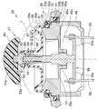
- FIG. 2is a cross-sectional view of a bending operation mechanism
- FIG. 4is a side view of the connecting member
- FIG. 5is a side view of the connecting member viewed from another direction
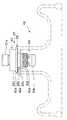
- FIG. 6is a cross-sectional view of the main part of the bending operation mechanism when the bending operation lever is tilted
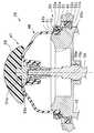
- 7is a cross-sectional view of the main part of the bending operation mechanism at the time of a leak test of the endoscope
- FIG. 8is a cross-sectional view showing a modification of the bending operation mechanism
- FIG. 9is an operation explanatory view of the elastic cover at the time of the leak test. .
- an endoscope apparatus 1includes an endoscope 2 and an image processing apparatus 3 (also referred to as an illumination light source built-in video processor or a camera control unit) that is an external device that also serves as a light source apparatus. It has and is configured as a medical device.
- an image processing apparatus 3also referred to as an illumination light source built-in video processor or a camera control unit
- the endoscope 2includes a long insertion portion 12, an operation portion 13 connected to the proximal end of the insertion portion 12, and an endoscope connector 20 connected to the image processing device 3. It is configured.
- the operation unit 13 of the endoscope 2 and the endoscope connector 20are connected via a flexible cable 16 (universal cord).
- the insertion portion 12includes a distal end portion 21 mainly formed of a metal member such as stainless steel, a bending portion 22 that can be bent flexibly, and a long rigid tube 23 formed of a metal tube such as stainless steel. It has in order from the front end side. That is, the endoscope 2 of the present embodiment is a surgical rigid endoscope in which the insertion portion 12 includes the bending portion 22.
- the distal end portion 21incorporates an imaging unit using a CCD sensor, a CMOS sensor or the like (not shown). From this imaging unit, a communication cable for driving control, an optical transmission fiber for high-speed transmission for transmitting an imaging signal, and the like. Is extended.
- a plurality of bending piecesare arranged in a line along the longitudinal direction inside the bending portion 22.
- the plurality of bending piecesare rotated with each other by pulling or loosening a plurality (for example, four) of bending operation wires (not shown), so that the bending portion 22 includes any arbitrary vertical and horizontal directions of the imaging unit. It is possible to bend in the direction.
- the bending portion 22is provided with a bending rubber 22a as an outer skin covering a plurality of bending pieces.
- each bending operation wire 60(see FIG. 2) whose tip is connected to the most advanced bending piece in the bending portion 22 is inserted.
- the operation unit 13includes a bending operation mechanism 25 for remotely operating the bending unit 22 via a bending operation wire 60, and various switches 26 for operating the image processing apparatus 3 and the like.
- built-in itemssuch as the above-described communication cable, optical transmission fiber, and light guide extending from the insertion unit 12 are inserted into the operation unit 13, and these built-in items are inside the flexible cable 16. And connected to the endoscope connector 20.
- the image processing apparatus 3includes a receptacle section 31 to which an endoscope connector 20 is connected to a front face section 30 that is an operation section of the image processing apparatus 3, a panel section 32 for operation and status display, and a power switch 33. And are provided.
- the image processing apparatus 3incorporates a halogen lamp (not shown) as a light source for supplying illumination light to the endoscope 2.
- the bending operation mechanism 25 of the present embodimentincludes a base unit 45 held by the operation unit main body 40 of the operation unit 13, a bending operation lever 47 supported by the base unit 45 so as to be tiltable, And an elastic cover 48 disposed between the base portion 45 and the bending operation lever 47.
- the base portion 45is made of, for example, a substantially cylindrical metal member, and the open end on the tip side of the base portion 45 is set as an opening 45 a through which the bending operation lever 47 can be inserted.
- the base end side of the base portion 45is inserted into the operation portion main body 40 through a base portion insertion hole 40a opened in the operation portion main body 40.
- a seal portion 50 for holding the base portion 45 in a watertight manner with respect to the operation portion main body 40is interposed between the outer periphery of the base portion 45 on the front end side and the base portion insertion hole 40a.
- the seal portion 50 of the present embodimentincludes a first holder ring 51 disposed on the outer peripheral portion on the distal end side of the base portion 45, an outer peripheral portion of the first holder ring 51, and a base portion insertion hole 40a. And a second holder ring 52 disposed between the inner periphery of the first holder ring 52 and the second holder ring 52.
- a part of the elastic cover 48is interposed between the inner peripheral surface of the first holder ring 51 and the outer peripheral portion on the distal end side of the base portion 45 (described later), whereby the first holder ring 51 is attached to the base.
- the part 45is held in a watertight state.
- a seal groove 52 ais provided around the inner periphery of the second holder ring 52.
- a seal ring 53 a made of an O-ring or the likeis held in the seal groove 52 a, and the second holder ring 52 is brought into contact with the first holder ring 51 by pressing the seal ring 53 a against the outer peripheral surface of the first holder ring 51. It is connected to the watertight.
- a seal groove 52 bis provided around the outer periphery of the second holder ring 52.
- a seal ring 53b made of an O-ring or the likeis held in the seal groove 52b, and the seal ring 53b is pressed against the inner peripheral surface of the base portion insertion hole 40a, so that the second holder ring 52 is connected to the operation portion main body. 40 is kept watertight.
- the bending operation lever 47is arranged on the shaft member 55, the wire pulling member 56 disposed on one end side (base end side) of the longitudinal axis of the shaft member 55, and the other end side (tip end side) of the shaft member 55.
- a connecting member 57provided; a tightening member 58 for fixing the connecting member 57 to the shaft member 55; and a finger holder 59 held by the shaft member 55 via the connecting member 57.
- the shaft member 55has one end side (base end side) in the longitudinal axis direction arranged inside the base portion 45 and the other end side (tip end side) outside the base portion 45 through the opening 45a (tip end side). Is protruding.
- a spherical body 55 ais provided in the middle part of the shaft member 55 (for example, between the wire pulling member 56 and the connecting member 57), and the spherical body 55 a slides with a spherical body receiver 45 c provided inside the base portion 45. It is connected freely.
- the shaft member 55is rotatably held with the sphere 55a as a fulcrum, and a predetermined angle (maximum tilt angle ⁇ : FIG. 6) from a neutral state (see FIG. 2) standing along the central axis of the base portion 45. It is possible to tilt in any direction up to (see).
- the wire pulling member 56is configured by, for example, a plate-like member in which four arm portions 56a are extended in different directions. More specifically, in the present embodiment, the wire pulling member 56 is configured by a cross-shaped plate member in which the angle formed by the adjacent arm portions 56a is set to 90 degrees, and the central portion thereof is the shaft member 55. It is fixed to the base end side. Thereby, the front end side of each arm part 56a can be displaced in conjunction with the tilting operation of the shaft member 55. In FIG. 2, only two arm portions 56a among the four arm portions 56a are illustrated.
- each bending operation wire 60 extending from the insertion portion 12 sideis connected to the distal end side of each arm portion 56a.
- the wire pulling member 56can pull or loosen each bending operation wire 60 in conjunction with the tilting operation of the shaft member 55 (the bending operation lever 47), and can bend the bending portion 22 in an arbitrary direction. It has become. That is, for example, the wire pulling member 56 causes the bending portion 22 to bend in the vertical direction when the shaft member 55 (the bending operation lever 47) is tilted in the front-rear direction of the operation portion 13, and the shaft member 55 (the bending operation lever 47). ) Is tilted in the left-right direction of the operation unit 13, the bending portion 22 can be bent in the left-right direction.
- the connecting member 57includes a head portion 61 to which the finger rest 59 is fixed, an insert portion 62 embedded in a part of the elastic cover 48, and a distal end side of the shaft member 55.
- the cylindrical portion 63 to be insertedis constituted by a metal integrally formed product that is continuously provided in order from the tip side.
- the head portion 61has a substantially cylindrical shape, and a projection 61 a for fixing the finger holding portion 59 is provided on the top of the head portion 61.
- the insert portion 62includes a first annular surface 62a having a larger diameter than the head portion 61, a second annular surface 62b having a different diameter from the first annular surface 62a, and a third annular surface having a different diameter from the second annular surface 62b.
- An annular surface 62cis formed adjacently in order from the tip side.
- an outward flange 62d having a diameter larger than that of the head portion 61is provided around the distal end side of the insert portion 62, and an outer peripheral surface of the outward flange 62d is set as a first annular surface 62a.
- the insert portion 62is provided with a recessed groove 62e having a smaller diameter than the outward flange 62d and adjacent to the proximal end side of the outward flange 62d, and the bottom surface of the recessed groove 62e serves as a second annular surface 62b. Is set.
- the insert portion 62is provided with an outward flange 62f having a diameter larger than that of the recessed groove 62e and adjacent to the proximal end side of the recessed groove 62e.
- the outer peripheral surface of the outward flange 62fis a third annular surface. 62c is set.
- the surface roughness of the first to third annular surfaces 62a to 62cis at least the other portion, that is, the connecting member 57 (curved) It is desirable that the surface roughness of the other part of the operation lever 47) is set to be the same as or rough.
- the outer diameters of the first to third annular surfaces 62a to 62cneed only be different from each other. For this reason, for example, the second annular surface 62b is replaced with the first and third annular surfaces 62a, It is also possible to form the outer peripheral surface of the outward flange having a larger diameter than the outward flanges 62d and 62f forming the 62c. Further, the third annular surface 62c can be omitted as appropriate.
- the cylindrical portion 63constitutes a so-called collet chuck type fixture together with the fastening member 58.
- the external thread side 63ais provided in the front end side outer periphery of the cylindrical part 63.
- a tapered surface 63bthat increases in diameter from the proximal end side toward the distal end side is formed on the outer periphery on the proximal end side of the cylindrical portion 63.
- a slit 63cis provided on the proximal end side of the cylindrical portion 63 to allow deformation of the portion in the radial direction (see FIGS. 4 and 5).
- the fastening member 58is configured by a cylindrical metal member that is externally mounted on the cylindrical portion 63 of the connecting member 57. On the inner periphery on the distal end side of the tightening member 58, a female screw portion 58a that is screwed with the male screw portion 63a of the cylindrical portion 63 is provided.
- a taper surface 58b that increases in diameter from the proximal end side toward the distal end sideis provided on the inner periphery on the proximal end side with respect to the female screw portion 58a of the fastening member 58.
- the tapered surface 58bis brought into contact with the tapered surface 63b of the cylindrical portion 63 when the female screw portion 58a is screwed into the male screw portion 63a of the cylindrical portion 63, and the female screw portion 58a with respect to the male screw portion 63a.
- the cylindrical portion 63is set to be deformed in the inner diameter direction as the screwing proceeds. Thereby, the tightening member 58 can firmly fix the connecting member 57 to the shaft member 55.
- the distal end side of the shaft member 55 and the cylindrical portion 63may be serrated to strengthen the rotation direction around the shaft.
- a nut portion 58cis provided to which a tool (not shown) is engaged when screwed with the male screw portion 63a.
- a taper surface 58dthat increases in diameter from the proximal end side toward the distal end side is provided on the outer periphery of the tightening member 58 on the distal end side of the nut portion 58c.
- the bending operation lever 47is proximal to the insert portion 62 (that is, a region surrounded by the elastic cover 48 as described later). Further, it has a tapered surface (tapered surface 58d) whose outer diameter decreases from the distal end side toward the proximal end side.
- each end portion of the nut portion 58c and the tapered surface 58d provided on the outer peripheral side of the fastening member 58is processed into an R shape by chamfering or the like.
- the finger holder 59is formed of an umbrella-shaped member that can contact the operator's finger, and is fixed to the shaft member 55 via a protrusion 61 a provided on the head portion 61 of the connecting member 57.
- the finger holder 59is formed to have an outer diameter larger than that of the shaft member 55, and a recess 59 a for avoiding interference with the elastic cover 48 is provided on the back side of the finger holder 59.
- the elastic cover 48is constituted by a flexible rubber molded product disposed so as to close the opening 45a of the base portion 45.
- the elastic cover 48is formed at the peripheral edge of the elastic cover 48 and is watertightly fixed to the base portion 45, and rises from the watertight fixing portion 65 to the top 66a set to the first height H1.
- the inner peripheral wall portion 68 that rises up to H2 and the central portion 69 that is connected to the inner peripheral side of the inner peripheral wall portion 68 and is fixed to the bending operation lever 47are formed by an integrally molded product in order from the outer peripheral side. .
- a series of portions from the outer peripheral wall portion 66 to the inner peripheral wall portion 68constitute a cover portion that surrounds the bending operation lever 47.
- the watertight fixing portion 65is configured by, for example, an O-ring shaped member formed on the outermost periphery of the elastic cover 48.
- the watertight fixing portion 65is held in a seal groove 45 b provided around the outer peripheral portion on the distal end side of the base portion 45.
- maintained at the seal groove 45bis press-contacted to the internal peripheral surface of the 1st holder ring 51,
- the base part 45is connected with the operation part main body 40 in a watertight state, and The elastic cover 48 is held so as not to be detached from the base portion 45 (the operation portion main body 40).
- the outer peripheral wall portion 66is configured by a substantially cylindrical member that is integrally formed so as to rise from the watertight fixing portion 65 toward the distal end side of the central axis of the bending operation lever 47.
- the valley portion 67is configured by a substantially donut-like member integrally formed so as to form a recess from the top portion 66a toward the opening portion 45a on the inner peripheral side of the outer peripheral wall portion 66.
- the valley portion 67includes a descending portion 67a that extends in a direction descending from the top portion 66a of the outer peripheral wall portion 66, and a bottom portion 67b that forms a flat portion on the inner peripheral side of the descending portion 67a. ing.
- the depth of the descending portion 67ais set to a predetermined depth D which is shallower than the first height H1.
- the radial width of the bottom 67bis set to a predetermined width W that is uniform over the entire circumference (over the front-rear and left-right directions of the operation unit 13), for example.
- the inner peripheral wall portion 68is configured by a substantially cylindrical member that is integrally formed so as to rise from the inner periphery of the trough portion 67 toward the distal end side of the central axis of the bending operation lever 47.
- the insert portion 62 of the connecting member 57is embedded on the inner peripheral side by insert molding. Thereby, the bending operation lever 47 is watertightly connected to the elastic cover 48.
- the central portion 69has, on the inner peripheral side, a first fixing portion 69 a that is tightly fixed to a first annular surface 62 a formed on the insert portion 62, and a second fixing portion 69 a.
- a second fixing portion 69b that is closely fixed to the annular surface 62b and a third fixing portion 69c that is closely fixed to the third annular surface 62care configured.
- the first to third fixing portions 69a to 69care formed following the shape of the insert portion 62 at the time of insert molding, and these first to third fixing portions 69a to 69c are the first to third annular surfaces 62a to 62a.
- the elastic cover 48is firmly connected to the bending operation lever 47 with high water-tightness by being closely fixed to 62c.
- the first fixing part 69ais tightly fixed to the first annular surface 62a, so that these joint interfaces are connected to the bending operation lever 47. It extends in the axial direction. Further, on the proximal end side of the joint portion between the first annular surface 62a and the first fixing portion 69a, the joint portion between the second annular surface 62b and the second fixing portion 69b having different diameters, the third annular surface 62c, and the second 3 Since the joint portion with the fixed portion 69c is continuously provided, the joint interface between the insert portion 62 and the central portion 69 has a labyrinth structure in cross section. When the third annular surface 62c of the insert portion 62 is omitted, the third fixing portion 69c of the center portion 69 is also omitted.
- the first height H1 to the top portion 66a of the outer peripheral wall portion 66is such that the top portion 66a at the neutral time has a locus L of the finger holding portion 59 when the bending operation lever 47 is tilted. It is set so as to be located inside (see FIG. 2).
- the first height H1 to the top 66a of the outer peripheral wall 66is equal to the case where the elastic cover 48 is deformed as the bending operation lever 47 tilts to a predetermined angle (maximum tilt angle ⁇ ).
- the finger holder 59is set to a height that does not contact the top 66a (see FIG. 6).
- the first height H1 to the top 66a of the outer peripheral wall 66is equal to that of the outer peripheral wall 66 even when the elastic cover 48 is deformed along with the inclination to the predetermined angle ⁇ by the bending operation lever 47.
- the heightis set so as not to contact the descending portion 67a (see FIG. 6).
- the elastic cover 48 of the present embodimenthas a total length (distance) from the peripheral edge portion (watertight fixing portion 65) to the central portion 69 when the outer peripheral wall portion 66, the valley portion 67, and the inner peripheral wall portion 68 are extended. ) Is set to be larger than the linear distance between the peripheral edge portion (watertight fixing portion 65) and the central portion 69 when the shaft member 55 is tilted to a predetermined angle (maximum tilt angle ⁇ ) ( (See FIG. 6).
- the setting of the first height H1 as described aboveis based on, for example, specifications such as the depth D of the descending portion 67a, the width W of the bottom 67b, and the elasticity and shape of the resin material constituting the elastic cover 48. In addition, it is performed based on experiments and simulations. In other words, in particular, the first height H1, the depth D of the descending portion 67a, and the width W of the bottom portion 67b are set in association with each other so as to satisfy the above-described requirements when the bending operation lever 47 is tilted. Yes.
- the watertight fixing portion 65as a peripheral portion that is watertightly fixed to the base portion 45 and the finger contact portion 59 do not contact when the shaft member 55 is tilted to the predetermined angle ⁇ .
- the outer peripheral wall 66rising from the watertight fixing portion 65 toward the top 66a formed at the height H1, the trough 67 connected to the inner peripheral side of the outer peripheral wall 66, and the inner peripheral side of the trough 67
- An inner peripheral wall portion 68that is continuously provided and rises to a second height H2 that is higher than the first height H1, and a central portion that is connected to the inner peripheral side of the inner peripheral wall portion 68 and is fixed to the bending operation lever 47.
- the elastic cover 48is configured and the elastic cover 48 is used to close the opening 45a of the base portion 45 in a watertight manner, whereby the bending operation with respect to the bending operation lever 47 is performed with good operability. be able to.
- the elastic cover 48in which the outer peripheral wall portion 66 and the inner peripheral wall portion 68 are provided on the outer peripheral side and the inner peripheral side through the valley portion 67, from the watertight fixing portion 65 that is the peripheral portion to the top portion 66a of the outer peripheral wall portion 66. Is set to a first height H1 at which the finger contact portion 59 does not come into contact with the top portion 66a when the shaft member 55 is tilted to a predetermined maximum tilt angle ⁇ , so that it is elastic when the bending operation lever 47 is tilted. It is possible to prevent the cover 48 and the finger holder 59 from interfering with each other.
- the reaction force that the bending operation lever 47 receives from the elastic cover 48 via the finger rest 59can be reduced, and the bending operation on the bending operation lever 47 can be performed with good operability. It can be carried out.
- the height of the inner peripheral wall portion 68 that is unlikely to be interfered with the finger holder 59 or the likeis set to a second height H2 that is higher than the first height H1, and the inner peripheral wall portion 68 can be elastically deformed.
- the heightis such that the inner peripheral wall portion 68 and the descending portion 67a are not in contact with each other.
- the first height H1it is possible to prevent the reaction force due to the deformation of the elastic cover 48 from increasing due to the interference between the inner peripheral wall portion 68 and the descending portion 67a when the bending operation lever 47 is tilted. Accordingly, the reaction force received from the elastic cover 48 via the shaft member 55 when the bending operation lever 47 is tilted can be reduced, and the bending operation on the bending operation lever 47 can be realized with better operability.
- the total length (distance) from the peripheral edge portion (watertight fixing portion 65) to the central portion 69 when the outer peripheral wall portion 66, the valley portion 67, and the inner peripheral wall portion 68 are extendedis determined to be a predetermined value.
- the tension generated by the deformation of the elastic cover 48is set to be larger than the linear distance between the peripheral edge portion (watertight fixing portion 65) and the central portion 69 when tilted to the angle (maximum tilt angle ⁇ ). Therefore, the bending operation with respect to the bending operation lever 47 can be realized with better operability.
- the first annular surface 62a formed at a predetermined position on the distal end side and the first annular surface formed adjacent to the proximal end side of the first annular surface 62aare: With respect to the bending operation lever 47 having the second annular surface 62b having a different diameter, a first fixing portion 69a that is closely fixed to the first annular surface 62a and a second fixing portion that is closely fixed to the second annular surface 62b.
- the first fixing portion 69a of the elastic coveris tightly fixed to the first annular surface 62a formed on the bending operation lever 47. Can be set along the axial direction of the bending operation lever 47.
- a cross-sectional shape having a labyrinth structurecan be formed at the connection interface between the bending operation lever 47 and the elastic cover 48.
- a joint portion between the third annular surface 62c and the third fixing portion 69c having different diametersis further provided on the proximal end side of the joint portion between the second annular surface 62b and the second fixing portion 69b.
- the bending operation lever 47has a tapered surface 58d whose outer diameter decreases toward the base end side. It is possible to prevent a step or the like that suddenly changes the outer diameter from being formed on the base end side of the insert portion 62 that is a joint portion of the above. Therefore, for example, when performing the autoclave sterilization or the like, even when the elastic cover 48 is pressed against the bending operation lever 47 by an external pressure or the like applied to the endoscope 2, the elastic cover 48 is brought into contact with a step or the like. Damage or the like can be prevented.
- the elastic cover 48expands due to an internal pressure or the like applied to the endoscope 2.
- 48has a trough portion 67 having a flat bottom portion 67b interposed between the outer peripheral wall portion 66 and the inner peripheral wall portion 68, thereby preventing a sudden deformation with respect to the applied internal pressure and being durable. Can be improved.
- the elastic cover 48 having the flat bottom portion 67bstarts to deform from a relatively low pressure state when the bottom portion 67b receives an internal pressure, so that it gradually increases as the pressure increases. (See timings T0 to T3). Further, when releasing the internal pressure, the elastic cover 48 gradually recovers from deformation as the pressure decreases. As a result, the elastic cover 48 is reliably restored to the initial shape at the end of the leak test.
- the elastic cover 148 in which the valley portion 167 is formed of a concave curved surface as a wholeis prevented from being deformed in a state where the internal pressure is relatively low (see timings T0 and T1). )
- the pressureexceeds a certain pressure, the shape of the valley 167 is rapidly reversed (see timings T2 and T3).
- the deformation of the elastic cover 148is maintained even if the pressure decreases.
- the elastic cover 148is not restored to the initial shape and remains expanded.
- the elastic cover 148When the bending operation lever is operated in this state, the elastic cover 148 is sandwiched between the finger holder 159 and the first and second holder rings 151 and 152. At this time, not only the reaction force that the bending operation lever 147 receives from the elastic cover 148 via the finger rest 159 increases, but the elastic cover 148 may be damaged.
- the above-described bending operation mechanism 25is formed in a substantially circular shape whose plan view shape is substantially symmetrical over the entire circumference, for example, the base portion 45 is formed in a cylindrical shape.
- the operability when operating the bending operation lever 47 in this stateis generally less operability in the left-right direction than the operability in the front-rear direction, etc.
- the plan view shape of the bending operation mechanism 25is a long diameter in the front-rear direction and a short diameter in the left-right direction.
- the present inventionis applied to a rigid endoscope including the rigid tube 23 in the insertion portion 12 .
- the present inventionis not limited to this, and for example, an insertion
- the present inventioncan also be applied to a flexible mirror having a soft tube at 12 in the part.
Landscapes
- Health & Medical Sciences (AREA)
- Life Sciences & Earth Sciences (AREA)
- Physics & Mathematics (AREA)
- Surgery (AREA)
- Engineering & Computer Science (AREA)
- Optics & Photonics (AREA)
- Medical Informatics (AREA)
- Public Health (AREA)
- Biophysics (AREA)
- Nuclear Medicine, Radiotherapy & Molecular Imaging (AREA)
- Pathology (AREA)
- Radiology & Medical Imaging (AREA)
- Veterinary Medicine (AREA)
- Biomedical Technology (AREA)
- Heart & Thoracic Surgery (AREA)
- General Health & Medical Sciences (AREA)
- Molecular Biology (AREA)
- Animal Behavior & Ethology (AREA)
- Mechanical Engineering (AREA)
- Astronomy & Astrophysics (AREA)
- General Physics & Mathematics (AREA)
- Instruments For Viewing The Inside Of Hollow Bodies (AREA)
- Endoscopes (AREA)
Abstract
Description
Translated fromJapanese本発明は、挿入部に設けられた湾曲部を湾曲操作レバーによって湾曲操作させる内視鏡の湾曲操作機構に関する。The present invention relates to a bending operation mechanism for an endoscope in which a bending portion provided in an insertion portion is bent by a bending operation lever.
従来、生体の体内など、観察が困難な被検体の内部の箇所を観察するために、被検体内に挿入可能な内視鏡が、例えば、医療分野において広く利用されている。この内視鏡は、被検体内に挿入される挿入部を有している。また、挿入部の先端側には湾曲部が設けられ、湾曲部は、内視鏡の操作部等に設けられた湾曲操作機構に対する手元操作に従い、所望する方向に自在に湾曲することが可能となっている。2. Description of the Related Art Conventionally, endoscopes that can be inserted into a subject have been widely used, for example, in the medical field in order to observe a portion inside a subject that is difficult to observe, such as a living body. This endoscope has an insertion portion that is inserted into a subject. Further, a bending portion is provided on the distal end side of the insertion portion, and the bending portion can be freely bent in a desired direction in accordance with a hand operation with respect to a bending operation mechanism provided in an operation portion or the like of the endoscope. It has become.
湾曲操作機構としては、任意の方向に傾倒可能な湾曲操作レバーを備えた、所謂ジョイスティック型の湾曲操作機構が知られている。このようなジョイスティック型の湾曲操作機構のベース部には、湾曲操作レバーを任意の方向に傾倒させるための開口部が設けられている。As a bending operation mechanism, a so-called joystick-type bending operation mechanism including a bending operation lever that can be tilted in an arbitrary direction is known. The base portion of such a joystick-type bending operation mechanism is provided with an opening for tilting the bending operation lever in an arbitrary direction.
また、例えば、日本国特開2016-55041号公報には、開口部を水密に封止するためのカバーとして、中央部分が凸状に張り出したキャップ形状をなし、且つ、開口側の縁部分に断面円形状の縁部分が形成されたゴムブーツ(弾性カバー)が開示されている。このようなゴムブーツの凸部に形成された穴部にはロッド(湾曲操作レバー)が挿通され、これらゴムブーツとロッドとは、内部に洗浄液等が入り込まないように水密に接続されている。Further, for example, in Japanese Patent Application Laid-Open No. 2016-55041, as a cover for sealing the opening in a water-tight manner, a cap shape with a central portion protruding in a convex shape is formed on the edge portion on the opening side. A rubber boot (elastic cover) in which an edge portion having a circular cross section is formed is disclosed. A rod (curving operation lever) is inserted into the hole formed in the convex portion of the rubber boot, and the rubber boot and the rod are connected in a watertight manner so that the cleaning liquid or the like does not enter the inside.
しかしながら、この種のカバーは、湾曲操作レバーの傾倒に伴って変形される場合以外にも、オートクレーブ滅菌或いはリークテスト等を行う際に、内視鏡の外部或いは内部に付与される圧力によっても変形される。However, this type of cover can be deformed not only when the bending operation lever is tilted but also by pressure applied to the exterior or interior of the endoscope when performing autoclave sterilization or a leak test. Is done.
従って、この種の内視鏡では、このような内視鏡の内外に付与される圧力に変化に対しても十分な耐久性を確保して水密性等を維持する必要がある。Therefore, in this type of endoscope, it is necessary to ensure sufficient durability against a change in pressure applied to the inside and outside of such an endoscope and maintain watertightness and the like.
本発明は上記事情に鑑みてなされたもので、内視鏡に付与される圧力の変化に対しても十分な耐久性を確保することができる内視鏡の湾曲操作機構を提供することを目的とする。The present invention has been made in view of the above circumstances, and an object thereof is to provide a bending operation mechanism of an endoscope that can ensure sufficient durability against a change in pressure applied to the endoscope. And
本発明の一態様による内視鏡の湾曲操作機構は、長手軸の基端側が回動自在に保持され、前記長手軸の先端側を傾倒させることにより挿入部に設けられた湾曲部を湾曲させる湾曲操作レバーと、前記湾曲操作レバーの前記先端側の所定の位置に形成された第1環状面と、前記第1環状面の前記基端側に隣接して前記湾曲操作レバーに形成された前記第1環状面とは異径の第2環状面と、前記第1環状面に密着固定される第1固定部と、前記第2環状面に密着固定される第2固定部と、前記第2固定部の前記基端側に延設されて前記湾曲操作レバーを囲繞するカバー部と、を有する弾性カバーと、を具備するものである。In the bending operation mechanism of the endoscope according to one aspect of the present invention, the proximal end side of the longitudinal axis is rotatably held, and the bending portion provided in the insertion portion is curved by tilting the distal end side of the longitudinal axis. A bending operation lever; a first annular surface formed at a predetermined position on the distal end side of the bending operation lever; and the bending operation lever formed adjacent to the base end side of the first annular surface. A second annular surface having a diameter different from that of the first annular surface; a first fixing portion that is closely fixed to the first annular surface; a second fixing portion that is closely fixed to the second annular surface; And an elastic cover having a cover portion that extends to the base end side of the fixed portion and surrounds the bending operation lever.
以下、図面を参照して本発明の形態を説明する。図面は本発明の一実施形態に係り、図1は内視鏡装置の構成を示す斜視図、図2は湾曲操作機構の断面図、図3は湾曲操作レバーの連結部材にインサート成型された弾性カバーの断面図、図4は連結部材の側面図、図5は連結部材を他の方向から見た側面図、図6は湾曲操作レバーを傾倒動作させたときの湾曲操作機構の要部断面図、図7は内視鏡のリークテスト時における湾曲操作機構の要部断面図、図8は湾曲操作機構の変形例を示す断面図、図9はリークテスト時における弾性カバーの動作説明図である。Hereinafter, embodiments of the present invention will be described with reference to the drawings. The drawings relate to an embodiment of the present invention, FIG. 1 is a perspective view showing the configuration of an endoscope apparatus, FIG. 2 is a cross-sectional view of a bending operation mechanism, and FIG. 4 is a side view of the connecting member, FIG. 5 is a side view of the connecting member viewed from another direction, and FIG. 6 is a cross-sectional view of the main part of the bending operation mechanism when the bending operation lever is tilted. 7 is a cross-sectional view of the main part of the bending operation mechanism at the time of a leak test of the endoscope, FIG. 8 is a cross-sectional view showing a modification of the bending operation mechanism, and FIG. 9 is an operation explanatory view of the elastic cover at the time of the leak test. .
図1に示すように、内視鏡装置1は、内視鏡2と、光源装置を兼ねた外部機器となる画像処理装置3(照明光源内蔵型ビデオプロセッサまたはカメラコントロールユニットとも言う)と、を医療機器として有して構成されている。As shown in FIG. 1, an endoscope apparatus 1 includes an
内視鏡2は、長尺な挿入部12と、この挿入部12の基端に連設された操作部13と、画像処理装置3に接続する内視鏡コネクタ20と、を有して主に構成されている。The
なお、内視鏡2の操作部13と内視鏡コネクタ20は、軟性ケーブル16(ユニバーサルコード)を介して接続されている。The
挿入部12は、主にステンレスなどの金属製部材から形成された先端部21と、柔軟に湾曲自在な湾曲部22と、ステンレスなどの金属管によって形成された長尺な硬性管23と、を先端側から順に有して構成されている。すなわち、本実施の形態の内視鏡2は、挿入部12に湾曲部22を備えた外科用の硬性鏡となっている。The
先端部21は、図示しないCCDセンサ、CMOSセンサなどを用いた撮像部が内蔵されており、この撮像部から、駆動制御用の通信ケーブルおよび撮像信号を伝送する高速伝送用の光伝送用ファイバ等が延設されている。The
湾曲部22の内部には、図示しない複数の湾曲駒が長手方向に沿って一列に並んで配設されている。これら複数の湾曲駒は、図示しない複数(例えば、4本)の湾曲操作ワイヤが牽引或いは弛緩されることによって相互に回転され、これにより、湾曲部22は撮像部の上下左右方向を含む任意の方向に湾曲することが可能となっている。また、湾曲部22には、複数の湾曲駒を覆う外皮として湾曲ゴム22aが設けられている。A plurality of bending pieces (not shown) are arranged in a line along the longitudinal direction inside the
硬性管23の内部には、先端部21の撮像部から延設された通信ケーブル及び光伝送用ファイバ、先端部21に照明光を伝送するためのライトガイド等が湾曲部22を経て挿通されているとともに、湾曲部22内の最先端の湾曲駒に先端が接続された各湾曲操作ワイヤ60(図2参照)が挿通されている。Inside the
操作部13には、湾曲操作ワイヤ60を介して湾曲部22を遠隔操作するための湾曲操作機構25、および、画像処理装置3などを操作するための各種スイッチ26が備えられている。The
また、操作部13の内部には、挿入部12から延在する上述の通信ケーブル、光伝送用ファイバ、および、ライトガイド等の内蔵物が挿通され、これらの内蔵物は、軟性ケーブル16の内部を経て内視鏡コネクタ20に接続されている。In addition, built-in items such as the above-described communication cable, optical transmission fiber, and light guide extending from the
画像処理装置3は、当該画像処理装置3の操作部である前面部30に、内視鏡コネクタ20が接続されるレセプタクル部31と、操作および状態表示のためのパネル部32と、電源スイッチ33と、が設けられている。なお、画像処理装置3内には、内視鏡2に照明光を供給するための光源として、図示しないハロゲンランプなどが内蔵されている。The
次に、湾曲操作機構25の構成について、以下に詳しく説明する。
図2に示すように、本実施形態の湾曲操作機構25は、操作部13の操作部本体40に保持されたベース部45と、ベース部45に傾倒可能に支持された湾曲操作レバー47と、ベース部45と湾曲操作レバー47との間に配設された弾性カバー48と、を有して構成されている。Next, the configuration of the
As shown in FIG. 2, the
ベース部45は、例えば、略円筒形状をなす金属部材によって構成され、このベース部45の先端側の開放端が湾曲操作レバー47を挿通可能な開口部45aとして設定されている。The
このベース部45の基端側は、操作部本体40に開口されたベース部挿入孔40aを通じて、操作部本体40内に挿入されている。The base end side of the
また、ベース部45の先端側の外周とベース部挿入孔40aとの間には、ベース部45を操作部本体40に対して水密に保持するためのシール部50が介装されている。Further, a
具体的に説明すると、本実施形態のシール部50は、ベース部45の先端側の外周部に配設された第1ホルダリング51と、第1ホルダリング51の外周部とベース部挿入孔40aの内周部との間に配設された第2ホルダリング52と、を有して構成されている。More specifically, the
第1ホルダリング51の内周面とベース部45の先端側の外周部との間には、弾性カバー48の一部が介装され(後述する)、これにより、第1ホルダリング51はベース部45に対して水密な状態にて保持されている。A part of the
第2ホルダリング52の内周部にはシール溝52aが周設されている。このシール溝52aにはOリング等からなるシールリング53aが保持され、このシールリング53aが第1ホルダリング51の外周面に圧接されることにより、第2ホルダリング52は第1ホルダリング51に対して水密に接続されている。A
また、第2ホルダリング52の外周部にはシール溝52bが周設されている。このシール溝52bにはOリング等からなるシールリング53bが保持され、このシールリング53bがベース部挿入孔40aの内周面に対して圧接されることにより、第2ホルダリング52は操作部本体40に対して水密に保持されている。Further, a
湾曲操作レバー47は、軸部材55と、この軸部材55の長手軸の一端側(基端側)に配設されたワイヤ牽引部材56と、軸部材55の他端側(先端側)に配設された連結部材57と、連結部材57を軸部材55に固定するための締付部材58と、連結部材57を介して軸部材55に保持された指当部59と、を有して構成されている。The
軸部材55は、長手軸方向の一端側(基端側)がベース部45の内側に配設されるとともに、他端側(先端側)が開口部45aを通じてベース部45の外側(先端側)に突出されている。The
この軸部材55の中途部(例えば、ワイヤ牽引部材56と連結部材57との間)には球体55aが設けられ、この球体55aは、ベース部45の内部に設けられた球体受け45cと摺動自在に連結されている。これにより、軸部材55は、球体55aを支点として回動自在に保持され、ベース部45の中心軸に沿って起立するニュートラル状態(図2参照)から所定の角度(最大傾倒角度θ:図6参照)までの任意の方向に傾倒することが可能となっている。A
ワイヤ牽引部材56は、例えば、4本のアーム部56aが互いに異なる方向に延出された板状の部材によって構成されている。本実施形態において、より具体的には、ワイヤ牽引部材56は、互いに隣接するアーム部56aのなす角度が90度に設定された十字状の板状部材によって構成され、その中心部が軸部材55の基端側に固定されている。これにより、各アーム部56aの先端側は、軸部材55の傾倒動作に連動して変位可能となっている。なお、図2においては、4本のアーム部56aのうち2本のアーム部56aのみを図示している。The
これら各アーム部56aの先端側には、挿入部12側から延在する各湾曲操作ワイヤ60の基端が接続されている。これにより、ワイヤ牽引部材56は、軸部材55(湾曲操作レバー47)の傾倒動作に連動して各湾曲操作ワイヤ60を牽引或いは弛緩させ、湾曲部22を任意の方向に湾曲動作させることが可能となっている。すなわち、ワイヤ牽引部材56は、例えば、軸部材55(湾曲操作レバー47)が操作部13の前後方向に傾倒されたとき湾曲部22を上下方向に湾曲動作させ、軸部材55(湾曲操作レバー47)が操作部13の左右方向に傾倒されたとき湾曲部22を左右方向に湾曲動作させることが可能となっている。The proximal end of each bending
例えば、図3~図5に示すように、連結部材57は、指当部59が固定されるヘッド部61と、弾性カバー48の一部に埋め込まれるインサート部62と、軸部材55の先端側が挿入される筒状部63と、が先端側から順に連設された金属製の一体成形品によって構成されている。For example, as shown in FIGS. 3 to 5, the connecting
ヘッド部61は略円柱形状をなし、このヘッド部61の頂部には、指当部59を固定するための突起部61aが設けられている。The
インサート部62には、ヘッド部61よりも大径の第1環状面62aと、第1環状面62aとは異径の第2環状面62bと、第2環状面62bとは異径の第3環状面62cと、が先端側から順に隣接して形成されている。The
具体的に説明すると、インサート部62の先端側には、ヘッド部61よりも大径の外向フランジ62dが周設され、この外向フランジ62dの外周面が第1環状面62aとして設定されている。また、インサート部62には、外向フランジ62dよりも小径の凹溝62eが、当該外向フランジ62dよりも基端側に隣接して周設され、この凹溝62eの底面が第2環状面62bとして設定されている。さらに、インサート部62には、凹溝62eよりも大径の外向フランジ62fが、当該凹溝62eよりも基端側に隣接して周設され、この外向フランジ62fの外周面が第3環状面62cとして設定されている。Specifically, an
ここで、弾性カバー48をインサート成型する際の界面の密着性を向上させるため、第1~第3環状面62a~62cの表面粗さは、少なくとも他の部分以上、すなわち、連結部材57(湾曲操作レバー47)の他の部分の表面粗さと同じか粗く設定されていることが望ましい。Here, in order to improve the adhesion of the interface when the
なお、第1~第3環状面62a~62cの外径は互いに隣接するもの同士が異径であればよく、このため、例えば、第2環状面62bを、第1,第3環状面62a,62cを形成する各外向フランジ62d、62fよりも大径の外向フランジの外周面によって形成することも可能である。さらに、第3環状面62cは、適宜省略することも可能である。The outer diameters of the first to third
図2,3に示すように、筒状部63は、締付部材58と共に、所謂コレットチャック式の固定具を構成するものである。このため、筒状部63の先端側外周には雄ネジ部63aが設けられている。また、筒状部63の基端側外周には、基端側から先端側に向けて拡径するテーパ面63bが形成されている。さらに、筒状部63の基端側には、当該部位の径方向への変形を許容するためのスリット63cが設けられている(図4,5参照)。As shown in FIGS. 2 and 3, the
締付部材58は、連結部材57の筒状部63に外装される筒状の金属部材によって構成されている。この締付部材58の先端側の内周には、筒状部63の雄ネジ部63aと螺合する雌ネジ部58aが設けられている。The
また、締付部材58の雌ネジ部58aよりも基端側の内周には、基端側から先端側に向けて拡径するテーパ面58bが設けられている。このテーパ面58bは、雌ネジ部58aが筒状部63の雄ネジ部63aに螺合された際に筒状部63のテーパ面63bに当接され、雄ネジ部63aに対する雌ネジ部58aの螺合が進むにつれて筒状部63を内径方向に変形させるように設定されている。これにより、締付部材58は、軸部材55に対して連結部材57を強固に固定することが可能となっている。この場合、軸部材55の先端側および筒状部63にセレーション加工を施し、軸回りの回転方向の固定を強化させてもよい。Also, a
さらに、締付部材58の基端部の外周には、雄ネジ部63aとの螺合時等に図示しない工具が係合されるナット部58cが設けられている。さらに、ナット部58cよりも先端側において、締付部材58の外周には、基端側から先端側に向けて拡径するテーパ面58dが設けられている。Further, on the outer periphery of the base end portion of the tightening
そして、このような締付部材58が連結部材57に締結されることにより、湾曲操作レバー47は、インサート部62よりも基端側(すなわち、後述のように弾性カバー48によって囲繞される領域)に、先端側から基端側に向かって外径が小さくなるテーパ面(テーパ面58d)を有する。When the
ここで、締付部材58の外周側に設けられたナット部58c及びテーパ面58dの各端部は、面取等によってR形状に加工されていることが望ましい。Here, it is desirable that each end portion of the
指当部59は、操作者の指を当接可能な傘状の部材によって構成され、連結部材57のヘッド部61に設けられた突起部61aを介して、軸部材55に固定されている。この指当部59は軸部材55よりも大きい外径に形成され、指当部59の裏面側には、弾性カバー48との干渉を回避するための凹部59aが設けられている。The
弾性カバー48は、ベース部45の開口部45aを塞ぐように配設される柔軟なゴム成型品によって構成されている。この弾性カバー48は、当該弾性カバー48の周縁部に形成されてベース部45に水密固定される水密固定部65と、水密固定部65から第1の高さH1に設定された頂部66aまで立ち上がる外周壁部66と、外周壁部66の内周側に連設された谷部67と、谷部67の内周側に連設されて第1の高さH1よりも高い第2の高さH2まで立ち上がる内周壁部68と、内周壁部68の内周側に連設されて湾曲操作レバー47に固定される中央部69と、を外周側から順に備えた一体成型品によって構成されている。なお、これら弾性カバー48の各構成のうち、外周壁部66から内周壁部68までの一連の部位は、湾曲操作レバー47を囲繞するカバー部を構成する。The
水密固定部65は、例えば、弾性カバー48の最外周に形成されたOリング状の部材によって構成されている。この水密固定部65は、ベース部45の先端側の外周部に周設されたシール溝45bに保持されている。そして、シール溝45bに保持された水密固定部65が第1ホルダリング51の内周面に圧接されることにより、ベース部45が操作部本体40に対して水密な状態にて連結され、且つ、弾性カバー48がベース部45(操作部本体40)に対して脱落不能に保持されている。The
外周壁部66は、水密固定部65から湾曲操作レバー47の中心軸の先端側に向けて立ち上がるように一体形成された略円筒状の部材によって構成されている。The outer
谷部67は、外周壁部66の内周側において、頂部66aから開口部45aに向けて窪みを形成するように一体形成された略ドーナツ盤状の部材によって構成されている。The
この谷部67は、外周壁部66の頂部66aから下降する方向に延在する下降部67aと、この下降部67aの内周側に平面部を形成する底部67bと、を有して構成されている。The
ここで、例えば、図3に示すように、下降部67aの深さは、第1の高さH1よりも浅い所定の深さDに設定されている。また、底部67bの径方向の幅は、例えば、全周にわたって(操作部13の前後左右方向にわたって)均一な所定の幅Wに設定されている。Here, for example, as shown in FIG. 3, the depth of the descending
内周壁部68は、谷部67の内周から湾曲操作レバー47の中心軸の先端側に向けて立ち上がるように一体形成された略円筒形状の部材によって構成されている。The inner
中央部69は、連結部材57のインサート部62が、インサート成型によって内周側に埋め込まれている。これにより、湾曲操作レバー47は、弾性カバー48と水密に連結されている。In the
具体的には、例えば、図3に示すように、中央部69は、内周側に、インサート部62に形成された第1環状面62aに密着固定される第1固定部69aと、第2環状面62bに密着固定される第2固定部69bと、第3環状面62cに密着固定される第3固定部69cと、を有して構成されている。Specifically, for example, as shown in FIG. 3, the
第1~第3固定部69a~69cはインサート成型時にインサート部62の形状に倣って形成されるものであり、これら第1~第3固定部69a~69cが第1~第3環状面62a~62cにそれぞれ密着固定されることにより、弾性カバー48は湾曲操作レバー47に対して高い水密性を有して強固に連結されている。The first to
この場合において、インサート部62と中央部69との終端(先端)において、第1環状面62aに対して第1固定部69aが密着固定することにより、これらの接合界面は、湾曲操作レバー47の軸心方向に延在されている。また、第1環状面62aと第1固定部69aとの接合部の基端側に、異径をなす第2環状面62bと第2固定部69bとの接合部及び第3環状面62cと第3固定部69cとの接合部が連設されていることから、インサート部62と中央部69との接合界面は断面形状がラビリンス構造をなしている。なお、インサート部62の第3環状面62cが省略されている場合には、中央部69の第3固定部69cについても省略される。In this case, at the terminal ends (tips) of the
ここで、このような弾性カバー48において、外周壁部66の頂部66aまでの第1の高さH1は、ニュートラル時における頂部66aが、湾曲操作レバー47の傾倒時における指当部59の軌跡Lよりも内側に位置するよう設定されている(図2参照)。Here, in such an
また、外周壁部66の頂部66aまでの第1の高さH1は、湾曲操作レバー47による所定の角度(最大傾倒角度θ)までの傾倒に伴って弾性カバー48が変形された場合にも、指当部59が頂部66aに接触しない高さに設定されている(図6参照)。In addition, the first height H1 to the top 66a of the outer
さらに、外周壁部66の頂部66aまでの第1の高さH1は、湾曲操作レバー47による所定の角度θまでの傾斜に伴って弾性カバー48が変形された場合にも、外周壁部66と下降部67aとが接触しない高さに設定されている(図6参照)。Further, the first height H1 to the top 66a of the outer
さらに、本実施形態の弾性カバー48は、外周壁部66と谷部67と内周壁部68とを伸展させたときの周縁部(水密固定部65)から中央部69までの合計長さ(道のり)が、軸部材55を所定の角度(最大傾倒角度θ)まで傾倒させたときの周縁部(水密固定部65)と中央部69との間の直線距離よりも大きくなるよう設定されている(図6参照)。Furthermore, the
なお、上述のような第1の高さH1の設定は、例えば、下降部67aの深さD、底部67bの幅W、弾性カバー48を構成する樹脂材料の弾性及び形状等の諸元を基に、実験やシミュレーション等に基づいて行われる。換言すれば、特に、第1の高さH1、下降部67aの深さD、底部67bの幅Wは、湾曲操作レバー47の傾倒時に上述の各要件を満たすよう、相互に関連付けて設定されている。The setting of the first height H1 as described above is based on, for example, specifications such as the depth D of the descending
このような実施形態によれば、ベース部45に水密固定される周縁部としての水密固定部65と、軸部材55を所定の角度θまで傾倒したときに指当部59が接触しない第1の高さH1に形成される頂部66aに向けて水密固定部65から立ち上がる外周壁部66と、外周壁部66の内周側に連設された谷部67と、谷部67の内周側に連設されて第1の高さH1よりも高い第2の高さH2まで立ち上がる内周壁部68と、内周壁部68の内周側に連設されて湾曲操作レバー47に固定される中央部と、を備えて弾性カバー48を構成し、このような弾性カバー48を用いてベース部45の開口部45aを水密に塞ぐことにより、湾曲操作レバー47に対する湾曲操作を良好な操作性にて行うことができる。According to such an embodiment, the
すなわち、谷部67を介して外周側及び内周側に外周壁部66及び内周壁部68が設けられた弾性カバー48において、周縁部である水密固定部65から外周壁部66の頂部66aまでの高さを、軸部材55を所定の最大傾倒角度θまで傾倒したときに指当部59が頂部66aに接触しない第1の高さH1に設定することにより、湾曲操作レバー47の傾倒時に弾性カバー48と指当部59とが干渉することを防止できる。従って、湾曲操作レバー47の傾倒時に、湾曲操作レバー47が指当部59を介して弾性カバー48から受ける反力を軽減することができ、湾曲操作レバー47に対する湾曲操作を良好な操作性にて行うことができる。That is, in the
また、指当部59等との干渉が想定されにくい内周壁部68の高さを第1の高さH1よりも高い第2の高さH2に設定し、内周壁部68における弾性変形可能な領域を十分に確保することにより、内周壁部68が湾曲操作レバー47から傾倒時に直接的に受ける加重を効率的に分散させることができ、湾曲操作レバー47の傾倒操作に対する抵抗をより軽減することができる。Further, the height of the inner
この場合において、湾曲操作レバー47による所定の角度θまでの傾倒に伴って弾性カバー48が変形された場合に、内周壁部68と下降部67aとを接触させない高さであることを条件に加味して第1の高さH1を設定することにより、湾曲操作レバー47の傾倒時に内周壁部68と下降部67aとが干渉して弾性カバー48の変形による反力が増大することを防止できる。従って、湾曲操作レバー47の傾倒時に弾性カバー48から軸部材55を介して受ける反力を軽減することができ、湾曲操作レバー47に対する湾曲操作をより良好な操作性にて実現することができる。In this case, when the
さらに、外周壁部66と谷部67と内周壁部68とを伸展させたときの周縁部(水密固定部65)から中央部69までの合計長さ(道のり)が、軸部材55を所定の角度(最大傾倒角度θ)まで傾倒させたときの周縁部(水密固定部65)と中央部69との間の直線距離よりも大きくなるよう設定することにより、弾性カバー48の変形により発生する張力を軽減することができ、湾曲操作レバー47に対する湾曲操作をより良好な操作性にて実現することができる。Further, the total length (distance) from the peripheral edge portion (watertight fixing portion 65) to the
また、このような実施形態によれば、先端側の所定の位置に形成された第1環状面62aと、第1環状面62aの基端側に隣接して形成された第1環状面とは異径の第2環状面62bと、を有する湾曲操作レバー47に対し、第1環状面62aに密着固定される第1固定部69aと、第2環状面62bに密着固定される第2固定部69bと、第2固定部69bよりも基端側に延設されて湾曲操作レバー47を囲繞するカバー部(外周壁部66、谷部67、及び、内周壁部68)と、を有する弾性カバー48を水密に連結することにより、内視鏡2に付与される圧力の変化に対しても十分な耐久性を確保することができる。Further, according to such an embodiment, the first
すなわち、湾曲操作レバー47と弾性カバー48との接続部の終端(先端)において、湾曲操作レバー47に形成した第1環状面62aに弾性カバーの第1固定部69aを密着固定することにより、これらの接合界面を湾曲操作レバー47の軸心方向に沿って設定することができる。加えて、第1環状面62aと第1固定部69aとの接合部の基端側に、異径をなす第2環状面62bと第2固定部69bとの接合部を連設することにより、湾曲操作レバー47と弾性カバー48との接続界面にラビリンス構造をなす断面形状を形成することができる。これらにより、インサート部62と中央部69との接合部よりも基端側に延在するカバー部が内視鏡2に付与される外圧や内圧等によって大きく弾性変形した場合にも、この弾性変形による応力が接続界面の終端まで伝達することを防止できる。従って、湾曲操作レバー47と弾性カバー48との接続界面において剥離等が発生することを防止でき、内視鏡2に付与される圧力の変化に対しても十分な耐久性を確保することができる。In other words, at the terminal end (tip) of the connection portion between the bending
この場合において、第2環状面62bと第2固定部69bとの接合部の基端側に、異径をなす第3環状面62cと第3固定部69cとの接合部をさらに連設することにより、より効果的に耐久性を向上することができる。In this case, a joint portion between the third
また、湾曲操作レバー47が弾性カバー48のカバー部によって囲繞される領域に、基端側に向かって外径が小さくなるテーパ面58dを有することにより、湾曲操作レバー47上において、弾性カバー48との接合部であるインサート部62よりも基端側に、外径を急激に変化させる段差等が形成されることを防止することができる。従って、例えば、オートクレーブ滅菌等を行う際に、内視鏡2に付与された外圧等によって弾性カバー48が湾曲操作レバー47に押し当てられた場合にも、段差等との接触による弾性カバー48の破損等を防止することができる。Further, in the region surrounded by the cover portion of the
また、例えば、図7に示すように、内視鏡2に対するリークテスト等を行う際には、内視鏡2に付与された内圧等によって弾性カバー48が膨張するが、本実施形態の弾性カバー48は、外周壁部66と内周壁部68との間に、平面状の底部67bを備えた谷部67が介装されていることから、付与された内圧に対する急激な変形を防止して耐久性を向上することができる。For example, as shown in FIG. 7, when performing a leak test or the like on the
すなわち、例えば、図9に示すように、平面状の底部67bを有する弾性カバー48は、当該底部67bが内圧を受けて比較的低い圧力状態から変形を開始するため、圧力の上昇に応じて徐々に変形が進んでいく(タイミングT0~T3参照)。また、内圧を解放する場合、弾性カバー48は、圧力の減少に応じて徐々に変形から復帰する。その結果、リークテスト終了時に弾性カバー48は初期の形状に確実に復元する。That is, for example, as shown in FIG. 9, the
これに対し、例えば、図10の比較例に示すように、谷部167が全体として凹曲面によって形成された弾性カバー148は、内圧が比較的低い状態における変形が抑制され(タイミングT0,T1参照)、ある圧力を超えた瞬間に谷部167の形状が急激に反転する(タイミングT2,T3参照)。また、内圧を解放する場合、圧力が減少しても弾性カバー148の変形は維持される。その結果、リークテスト完了時に弾性カバー148は初期の形状に復元せず、膨張したままになる。この状態で湾曲操作レバーを操作すると、弾性カバー148は指当部159と第1,第2ホルダリング151,152の間に挟まれる。このとき、湾曲操作レバー147が指当部159を介して弾性カバー148から受ける反力が増大するだけでなく、弾性カバー148が破損するおそれがある。On the other hand, for example, as shown in the comparative example of FIG. 10, the
さらに、リークテスト等によって内視鏡2に付与した内圧を解放した際に、弾性カバー48を元の形状に速やかに復元させるため、例えば、図8に示すように、指当部59の基端側に突出する凸面部59bを、内周壁部68に近接させて設けることも可能である。Furthermore, in order to quickly restore the
ここで、上述の湾曲操作機構25は、ベース部45を円筒形状に形成する等、平面視形状が全周にわたって略対称な略円形に形成されるものであるが、例えば、操作部13を把持した状態において湾曲操作レバー47を操作する際の操作性が、一般に、前後方向の操作性に比べて左右方向の操作性が低いこと等を勘案し、前後方向と左右方向とで非対称な平面視形状とすることも可能である。すなわち、特に、湾曲操作レバー47に対する左右方向への傾倒操作の操作性を向上するため、例えば、湾曲操作機構25の平面視形状を、操作部13の前後方向を長径、左右方向を短径とする略楕円形に形成することも可能である
なお、本発明は、以上説明した各実施形態に限定されることなく、種々の変形や変更が可能であり、それらも本発明の技術的範囲内である。Here, the above-described
例えば、上述の実施形態においては、挿入部12に硬性管23を備えた硬性鏡に本発明を適用した場合の一例について説明したが、本発明はこれに限定されるものではなく、例えば、挿入部に12に軟性管を備えた軟性鏡に対しても適用が可能であることは勿論である。For example, in the above-described embodiment, an example in which the present invention is applied to a rigid endoscope including the
本出願は、2016年7月25日に日本国に出願された特願2016-145723号を優先権主張の基礎として出願するものであり、上記の開示内容は、本願明細書、請求の範囲に引用されるものとする。This application is filed on the basis of the priority claim of Japanese Patent Application No. 2016-145723 filed in Japan on July 25, 2016. The above disclosure is included in the present specification and claims. Shall be quoted.
Claims (6)
Translated fromJapanese前記湾曲操作レバーの前記先端側の所定の位置に形成された第1環状面と、
前記第1環状面の前記基端側に隣接して前記湾曲操作レバーに形成された前記第1環状面とは異径の第2環状面と、
前記第1環状面に密着固定される第1固定部と、前記第2環状面に密着固定される第2固定部と、前記第2固定部の前記基端側に延設されて前記湾曲操作レバーを囲繞するカバー部と、を有する弾性カバーと、
を具備することを特徴とする内視鏡の湾曲操作機構。A bending operation lever for bending the bending portion provided in the insertion portion by tilting the distal end side of the longitudinal axis, the proximal end side of the longitudinal axis being rotatably held;
A first annular surface formed at a predetermined position on the distal end side of the bending operation lever;
A second annular surface having a different diameter from the first annular surface formed on the bending operation lever adjacent to the base end side of the first annular surface;
A first fixing portion that is closely fixed to the first annular surface; a second fixing portion that is closely fixed to the second annular surface; and the bending operation that extends to the base end side of the second fixing portion. An elastic cover having a cover portion surrounding the lever;
A bending operation mechanism for an endoscope, comprising:
前記弾性カバーは、前記第3環状面に密着固定される第3固定部を有することを特徴とする請求項2に記載の内視鏡の湾曲操作機構。The bending operation lever includes a third annular surface having a diameter different from that of the second annular surface between the second annular surface and the tapered surface.
The endoscope bending operation mechanism according to claim 2, wherein the elastic cover includes a third fixing portion that is closely fixed to the third annular surface.
前記指当部には、前記基端側に突出する凸面部が形成されていることを特徴とする請求項1に記載の内視鏡の湾曲操作機構。The tip of the bending operation lever is provided with an umbrella-like finger rest that abuts the operator's finger,
The bending operation mechanism for an endoscope according to claim 1, wherein a convex surface portion that protrudes toward the base end side is formed in the finger contact portion.
Priority Applications (3)
| Application Number | Priority Date | Filing Date | Title |
|---|---|---|---|
| CN201780034842.0ACN109310276B (en) | 2016-07-25 | 2017-02-24 | Bending operation mechanism of endoscope |
| JP2017544049AJP6234650B1 (en) | 2016-07-25 | 2017-02-24 | Endoscope bending operation mechanism |
| US16/254,740US20190150707A1 (en) | 2016-07-25 | 2019-01-23 | Bending control mechanism for an endoscope |
Applications Claiming Priority (2)
| Application Number | Priority Date | Filing Date | Title |
|---|---|---|---|
| JP2016-145723 | 2016-07-25 | ||
| JP2016145723 | 2016-07-25 |
Related Child Applications (1)
| Application Number | Title | Priority Date | Filing Date |
|---|---|---|---|
| US16/254,740ContinuationUS20190150707A1 (en) | 2016-07-25 | 2019-01-23 | Bending control mechanism for an endoscope |
Publications (1)
| Publication Number | Publication Date |
|---|---|
| WO2018020718A1true WO2018020718A1 (en) | 2018-02-01 |
Family
ID=61017567
Family Applications (1)
| Application Number | Title | Priority Date | Filing Date |
|---|---|---|---|
| PCT/JP2017/007160CeasedWO2018020718A1 (en) | 2016-07-25 | 2017-02-24 | Bending operation mechanism for endoscope |
Country Status (3)
| Country | Link |
|---|---|
| US (1) | US20190150707A1 (en) |
| CN (1) | CN109310276B (en) |
| WO (1) | WO2018020718A1 (en) |
Cited By (1)
| Publication number | Priority date | Publication date | Assignee | Title |
|---|---|---|---|---|
| WO2021079506A1 (en)* | 2019-10-25 | 2021-04-29 | オリンパス株式会社 | Insertion apparatus |
Families Citing this family (8)
| Publication number | Priority date | Publication date | Assignee | Title |
|---|---|---|---|---|
| WO2018098465A1 (en) | 2016-11-28 | 2018-05-31 | Inventio, Inc. | Endoscope with separable, disposable shaft |
| WO2020161864A1 (en)* | 2019-02-07 | 2020-08-13 | オリンパス株式会社 | Endoscope |
| WO2021084577A1 (en)* | 2019-10-28 | 2021-05-06 | オリンパス株式会社 | Endoscope |
| USD1018844S1 (en) | 2020-01-09 | 2024-03-19 | Adaptivendo Llc | Endoscope handle |
| USD1051380S1 (en) | 2020-11-17 | 2024-11-12 | Adaptivendo Llc | Endoscope handle |
| USD1070082S1 (en) | 2021-04-29 | 2025-04-08 | Adaptivendo Llc | Endoscope handle |
| USD1031035S1 (en) | 2021-04-29 | 2024-06-11 | Adaptivendo Llc | Endoscope handle |
| USD1066659S1 (en) | 2021-09-24 | 2025-03-11 | Adaptivendo Llc | Endoscope handle |
Citations (3)
| Publication number | Priority date | Publication date | Assignee | Title |
|---|---|---|---|---|
| JP2003135385A (en)* | 2001-10-31 | 2003-05-13 | Olympus Optical Co Ltd | Endoscope apparatus |
| US20130102846A1 (en)* | 2011-10-21 | 2013-04-25 | Viking Systems, Inc. | Steerable electronic stereoscopic endoscope |
| WO2015156046A1 (en)* | 2014-04-11 | 2015-10-15 | オリンパス株式会社 | Endoscope |
Family Cites Families (6)
| Publication number | Priority date | Publication date | Assignee | Title |
|---|---|---|---|---|
| CN201661697U (en)* | 2010-03-11 | 2010-12-01 | 浙江固特气动机械有限公司 | Soft-sealing butterfly valve |
| CN203232081U (en)* | 2013-05-17 | 2013-10-09 | 虞旭海 | Current sensor |
| CN103410815B (en)* | 2013-08-08 | 2016-04-20 | 泉州市一鸣交通电器有限公司 | A kind of storage battery state indicator composite type installation sleeve |
| WO2016052147A1 (en)* | 2014-10-03 | 2016-04-07 | オリンパス株式会社 | Endoscope provided with bending operation mechanism |
| CN105411517B (en)* | 2015-12-01 | 2017-11-21 | 中南大学湘雅三医院 | A kind of vagina scope leakage-proof apparatus |
| CN205167396U (en)* | 2015-12-09 | 2016-04-20 | 荣昌精密机械(苏州)有限公司 | Nozzle for injection molding machine |
- 2017
- 2017-02-24WOPCT/JP2017/007160patent/WO2018020718A1/ennot_activeCeased
- 2017-02-24CNCN201780034842.0Apatent/CN109310276B/enactiveActive
- 2019
- 2019-01-23USUS16/254,740patent/US20190150707A1/ennot_activeAbandoned
Patent Citations (3)
| Publication number | Priority date | Publication date | Assignee | Title |
|---|---|---|---|---|
| JP2003135385A (en)* | 2001-10-31 | 2003-05-13 | Olympus Optical Co Ltd | Endoscope apparatus |
| US20130102846A1 (en)* | 2011-10-21 | 2013-04-25 | Viking Systems, Inc. | Steerable electronic stereoscopic endoscope |
| WO2015156046A1 (en)* | 2014-04-11 | 2015-10-15 | オリンパス株式会社 | Endoscope |
Cited By (1)
| Publication number | Priority date | Publication date | Assignee | Title |
|---|---|---|---|---|
| WO2021079506A1 (en)* | 2019-10-25 | 2021-04-29 | オリンパス株式会社 | Insertion apparatus |
Also Published As
| Publication number | Publication date |
|---|---|
| US20190150707A1 (en) | 2019-05-23 |
| CN109310276A (en) | 2019-02-05 |
| CN109310276B (en) | 2021-10-26 |
Similar Documents
| Publication | Publication Date | Title |
|---|---|---|
| WO2018020718A1 (en) | Bending operation mechanism for endoscope | |
| JP6053999B2 (en) | Endoscope with bending operation mechanism | |
| US8206287B2 (en) | Endoscope having flexible tube | |
| US20170027421A1 (en) | Endoscope | |
| US20180333040A1 (en) | Cover member of bending operation lever and endoscope including cover member of bending operation lever | |
| US20160363757A1 (en) | Endoscope | |
| JP6713879B2 (en) | Endoscope | |
| JP6270670B2 (en) | Bending operation mechanism and endoscope having bending operation mechanism | |
| JP6234650B1 (en) | Endoscope bending operation mechanism | |
| JP6234649B1 (en) | Bending operation mechanism of medical equipment | |
| WO2018020717A1 (en) | Bending operation mechanism for medical apparatus | |
| US10918266B2 (en) | Endoscope | |
| JP2009285304A (en) | Endoscope | |
| JP3745139B2 (en) | Endoscope | |
| JP3776816B2 (en) | Endoscope | |
| JPH10286229A (en) | Image-pickup device for endoscope | |
| JP2009045084A (en) | Endoscope operation device | |
| JP5186153B2 (en) | Endoscope bending structure | |
| WO2017090667A1 (en) | Endoscope system | |
| JP4005088B2 (en) | Endoscope | |
| JP3662086B2 (en) | Endoscope | |
| JP2009183619A (en) | Endoscope | |
| JP2005131435A (en) | Endoscope | |
| JP4483999B2 (en) | Universal cord connection structure of endoscope | |
| JPH06118315A (en) | Focus fixing device of endoscope |
Legal Events
| Date | Code | Title | Description |
|---|---|---|---|
| ENP | Entry into the national phase | Ref document number:2017544049 Country of ref document:JP Kind code of ref document:A | |
| 121 | Ep: the epo has been informed by wipo that ep was designated in this application | Ref document number:17833729 Country of ref document:EP Kind code of ref document:A1 | |
| NENP | Non-entry into the national phase | Ref country code:DE | |
| 122 | Ep: pct application non-entry in european phase | Ref document number:17833729 Country of ref document:EP Kind code of ref document:A1 |