WO2018016028A1 - Refrigeration cycle device - Google Patents
Refrigeration cycle deviceDownload PDFInfo
- Publication number
- WO2018016028A1 WO2018016028A1PCT/JP2016/071273JP2016071273WWO2018016028A1WO 2018016028 A1WO2018016028 A1WO 2018016028A1JP 2016071273 WJP2016071273 WJP 2016071273WWO 2018016028 A1WO2018016028 A1WO 2018016028A1
- Authority
- WO
- WIPO (PCT)
- Prior art keywords
- compressors
- refrigerant
- compressor
- pressure
- time
- Prior art date
- Legal status (The legal status is an assumption and is not a legal conclusion. Google has not performed a legal analysis and makes no representation as to the accuracy of the status listed.)
- Ceased
Links
Images


Classifications
- F—MECHANICAL ENGINEERING; LIGHTING; HEATING; WEAPONS; BLASTING
- F25—REFRIGERATION OR COOLING; COMBINED HEATING AND REFRIGERATION SYSTEMS; HEAT PUMP SYSTEMS; MANUFACTURE OR STORAGE OF ICE; LIQUEFACTION SOLIDIFICATION OF GASES
- F25B—REFRIGERATION MACHINES, PLANTS OR SYSTEMS; COMBINED HEATING AND REFRIGERATION SYSTEMS; HEAT PUMP SYSTEMS
- F25B1/00—Compression machines, plants or systems with non-reversible cycle
Definitions
- This inventionrelates to a refrigeration cycle apparatus.
- the present inventionrelates to a refrigeration cycle apparatus having a plurality of compressors.
- refrigeration cycle devicessuch as a refrigerator and a chiller unit, in which a refrigerant circuit is configured by sequentially connecting at least a compressor, a condenser, an expansion valve, and an evaporator.
- a refrigerating-cycle apparatuscomprised by piping connecting a some compressor in parallel.
- a starting method called “sequential start”is a method in which the next compressor is started after a certain time (generally 10 seconds or more) has elapsed, and the next compressor is started after a certain time (typically 10 seconds or more). It is known (for example, refer to Patent Document 1).
- each compressoris driven by a star delta start system.
- the star delta start methodis a start method that can reduce the starting current to 1/3 of the start method called direct-input start by performing star start that starts with a star connection for a predetermined time at start. . In starting, the time until the starting current decreases is called the starting time.
- the drive time for star connectionis generally set longer than the start time.
- the compressoris driven by the star connection for a set time, the compressor is switched to the delta connection, and the steady drive by the delta connection is performed.
- star start of the next compressoris started.
- the present inventionhas been made to solve the above-described problems, and an object of the present invention is to provide a refrigeration cycle apparatus that suppresses a starting current and has high followability to a refrigeration load.
- a plurality of compressors, a condenser, a decompression device, and an evaporatorare connected by piping to constitute a refrigerant circuit in which refrigerant is circulated, and the plurality of compressors are connected by piping in parallel.
- an inverter devicethat drives the plurality of compressors at a rotation speed corresponding to a drive frequency related to AC conversion, and a control device that controls the inverter device so as to start the plurality of compressors simultaneously or within a predetermined time.
- a plurality of compressors whose rotational speeds are controlled by the inverter deviceare connected in parallel, and the control device starts the plurality of compressors simultaneously or within a predetermined time.
- the refrigeration capacity following the loadcan be supplied in a shorter time than in the past.
- the inverter devicecontrols the drive frequency, the starting current that flows when starting the compressor can be made smaller than the current in the star delta start, so the electric capacity of the power supply equipment and the size of the power supply line Can be made smaller than before, and the cost can be reduced.
- FIG. 1is a diagram showing a configuration of a refrigeration cycle apparatus according to Embodiment 1 of the present invention.
- the refrigerator 100has a refrigerant circuit configured by connecting a plurality of compressors 11, a condenser 12, a decompressor 13, and an evaporator 14 through refrigerant piping.
- the refrigerator 100 according to the first embodimentcirculates the refrigerant filled in the refrigerant circuit, cools the air in the cooling target space, and performs refrigeration, freezing, and the like of the objects stored in the cooling target space.
- Non-azeotropic mixed refrigerantincludes, for example, R407C (R32 / R125 / R134a) which is an HFC (hydrofluorocarbon) refrigerant.
- Examples of the pseudoazeotropic refrigerant mixtureinclude R410A (R32 / R125) and R404A (R125 / R143a / R134a), which are HFC refrigerants.
- Examples of the single refrigerantinclude R22, which is an HCFC (hydrochlorofluorocarbon) refrigerant, and R134a, which is an HFC refrigerant.
- the compressor 11sucks the refrigerant, compresses it, and discharges it in a high temperature / high pressure state.
- the compressor 11 according to the first embodimentis configured by a compressor of a type that can adjust the refrigerant capacity by controlling the rotation speed while keeping the torque constant in accordance with the drive frequency of the inverter device 19.
- the refrigerator 100 according to Embodiment 1has a configuration in which four compressors 11A to 11D are connected in parallel in a refrigerant circuit.
- the inverter device 19has a switching element, for example, and performs DC-AC conversion to supply power to the compressor 11. At this time, the number of rotations of the compressor 11 can be arbitrarily changed according to the drive frequency at the time of conversion.
- the inverter devices 19A to 19Dsupply power to the compressors 11A to 11D, respectively.
- the compression method of the compressor 11is not particularly limited. For example, any of a reciprocating type, a rotary type, and a speed type may be sufficient. Further, the plurality of compressors 11 need not all be the same compression method.
- the condenser 12exchanges heat between air outside the space to be cooled and the compressed refrigerant from the compressor 11 and air, for example, to condense and liquefy the refrigerant.
- the condenser 12is used to condense the refrigerant, but a heat radiator may be used instead of the condenser to radiate heat to the refrigerant.
- the decompression device 13decompresses and expands the refrigerant.
- a flow rate control meanssuch as an electronic expansion valve, a refrigerant flow rate adjustment means such as an expansion valve having a temperature sensing cylinder, and the like are used.
- the evaporator 14performs heat exchange between the refrigerant whose pressure is reduced by the decompression device 13 and the air in the space to be cooled, evaporates and vaporizes the refrigerant, and cools the air.
- the condensing fan 15allows air outside the space to be cooled to pass through the condenser 12, for example.
- the evaporation side fan 16passes the air of cooling object space through the evaporator 14, for example, and sends it out to cooling object space again.
- the control device 20is a device composed of, for example, a microcomputer having a CPU (Central Processing Unit).
- the control device 20controls equipment that constitutes the refrigerator 100.
- the control device 20controls the drive frequency of the inverter device 19 particularly when the plurality of compressors 11 are started. Then, the starting current relating to the plurality of compressors 11 is suppressed.
- each component device of the refrigerator 100will be described based on the flow of the refrigerant circulating in the refrigerant circuit.
- the compressor 11sucks the refrigerant, compresses it, and discharges it in a high temperature / high pressure state.
- the discharged refrigerantflows into the condenser 12.
- the condenser 12exchanges heat between the air outside the cooling target space supplied by the condensation side fan 15 and the refrigerant, and condenses and liquefies the refrigerant.
- the condensed and liquefied refrigerantpasses through the decompression device 13.
- the decompression device 13decompresses the refrigerant that has condensed and passed therethrough.
- the decompressed refrigerantflows into the evaporator 14.
- the evaporator 14exchanges heat between the air in the space to be cooled supplied by the evaporation side fan 16 and the refrigerant to evaporate the refrigerant. Then, the compressor 11 sucks the evaporated gas refrigerant.
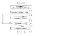
- FIG. 2is a diagram for explaining the operation at the start of the refrigerator 100 according to Embodiment 1 of the present invention.
- the control device 20When operating the refrigerator 100, the control device 20 outputs a compressor operation command to each inverter device 19 (step S1).
- Each inverter device 19adjusts the drive frequency based on the compressor operation command, and drives the compressor 11 at, for example, the minimum number of revolutions at which refrigerant can be sucked and discharged (step S2).
- step S2By outputting the compressor operation command to each inverter device 19 at the same time, all the compressors 11 related to the driving start at the same time, or all the compressors 11 can be regarded as being driven at the same time. Within (for example, within 10 seconds).
- the control device 20increases the drive frequency of each inverter device 19 and increases the rotation speed of each compressor 11 (step S3).
- the control apparatus 20controls the drive frequency in each inverter apparatus 19 so that the rotation speed of each compressor 11 may become the same. By making the rotational speed the same and the capacity the same, it can be expected that the distribution of the refrigerant and the refrigerating machine oil is less likely to be biased.
- the control apparatus 20judges whether the drive frequency of each inverter apparatus 19 became a predetermined rated frequency (step S4).
- the rated frequencyis a driving frequency corresponding to the rotational speed in steady driving in which the compressor 11 is driven stably.
- load follow-up frequency controlfor changing the drive frequency of each inverter device 19 corresponding to the refrigeration load and supplying the refrigeration capacity according to the refrigeration load is performed. (Step S5).
- FIG. 3is a diagram showing an outline of the relationship between current and time including start-up in the compressor 11 according to Embodiment 1 of the present invention.
- FIG. 3 (a)shows the relationship between current and time including start-up in the first embodiment.
- FIG.3 (b)shows the relationship between the electric current including the time of starting in the conventional refrigerator, and time for a comparison.
- FIG. 3shows the current supplied to one compressor 11 and the current supplied to four compressors. Basically, the current supplied to the four compressors 11 is obtained by superimposing four currents in the single compressor 11.
- the current valuetemporarily increases.
- the control device 20controls the drive frequency of the inverter device 19 to drive the compressor 11 at the lowest rotation speed, the starting current is smaller than the current in steady driving. And if the rotation speed of the compressor 11 goes up and the compressor 11 becomes a steady drive, an electric current will be stabilized.
- the drive current in the compressor 11 after the stable statechanges depending on the operating conditions of the refrigerator 100 by the refrigeration load. From the above, the capacity of the power supply equipment, the size of the power supply line, etc. may be selected based on the current when the compressor 11 is driven at the rotational speed in the steady drive.
- FIG. 4is a diagram showing an outline of the relationship between the refrigeration capacity including the start-up and time in the refrigerator 100 according to Embodiment 1 of the present invention.
- the relationship between the refrigerating capacity and time including the starting time in the conventional refrigeratoris also shown for comparison.
- Each of the plurality of compressors 11 mounted on the refrigerator 100gradually increases in operating frequency from the start at the same timing. As the driving frequency increases, the amount of refrigerant gas sucked and discharged by the compressor 11 increases. Since the amount of refrigerant circulating in the refrigerant circuit increases, the refrigeration capacity increases.
- the plurality of compressors 11 having the inverter device 19can be driven at the same time.
- the refrigeration capacity corresponding to the loadcan be supplied quickly.
- the effectincreases as the cooling capacity to be supplied increases.
- air in a living room for air conditioning applications, meat and fish in a refrigerated warehouse for refrigeration applications, and vegetables, fresh flowers, etc. in a refrigerator for refrigeration applicationscan be quickly moved to a desired temperature. Can be reached. Thereby, it can contribute to provision of comfortable space, food with high freshness, and the like.
- the compressor 11can be driven at the minimum number of revolutions, so that the starting current in the compressor 11 is made higher than the current in steady driving. It can be kept small. For this reason, the electric capacity of the power supply facility and the size of the power supply line can be selected based on the current in steady driving, and the cost can be suppressed.
- Embodiment 2FIG. In the first embodiment described above, all the compressors 11 are started within a predetermined time (for example, 10 seconds) that can be regarded as simultaneous or equivalent. However, if all the compressors 11 are started simultaneously or within, for example, 10 seconds, the opening degree of the decompression device 13 cannot be adjusted in time, and a follow-up delay may occur. If the follow-up of the decompression device 13 is delayed, the refrigerant pressure on the low pressure side of the refrigerant circuit may drop, and may stop due to a low pressure drop abnormality.
- a predetermined timefor example, 10 seconds
- the opening degree of the decompression device 13cannot be adjusted in time, and a follow-up delay may occur. If the follow-up of the decompression device 13 is delayed, the refrigerant pressure on the low pressure side of the refrigerant circuit may drop, and may stop due to a low pressure drop abnormality.
- the drive frequency of the inverter device 19is adjusted based on the detection by the low pressure side pressure detection device 21 so that the pressure on the low pressure side of the refrigerant circuit does not become lower than the set pressure. It is.
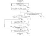
- FIG. 5is a diagram for explaining the operation at the start of the refrigerator 100 according to the second embodiment of the present invention.
- the equipment configuration of the refrigerator 100 in the second embodimentis the same as that in the first embodiment.
- the control device 20When operating the refrigerator 100, the control device 20 outputs a compressor operation command to each inverter device 19 (step S11).
- Each inverter device 19adjusts the drive frequency based on the compressor operation command, and drives the compressor 11 at the minimum rotational speed (step S12).
- control device 20determines whether or not the low pressure is higher than the set pressure (step S13). If it is determined that the low pressure is not higher than the set pressure (the low pressure is equal to or lower than the set pressure), the drive frequency of each inverter device 19 is maintained (step S14).
- step S15the drive frequency of each inverter device 19 is increased to increase the rotation speed of each compressor 11 (step S15).
- the control apparatus 20judges whether the drive frequency of each inverter apparatus 19 became a predetermined rated frequency (step S16).
- load follow-up frequency controlfor changing the drive frequency of each inverter device 19 corresponding to the refrigeration load and supplying the refrigeration capacity according to the refrigeration load is performed. (Step S17).
- FIG. 6is a diagram showing an outline of the relationship between the current, including the starting time, the pressure on the low pressure side of the refrigerant circuit, and time in the compressor 11 according to Embodiment 2 of the present invention. As shown in FIG. 6, when the pressure on the low pressure side of the refrigerant circuit is equal to or lower than the set pressure, the driving frequency in the inverter device 19 is maintained to prevent the low pressure side pressure from decreasing.
- the inverter device 19Since the drive frequency at is maintained, low pressure drop abnormality can be prevented. For this reason, the abnormal stop at the time of starting can be avoided, and the refrigerating capacity according to the refrigerating load can be quickly supplied.
- Embodiment 3FIG.
- the inverter device 19is installed corresponding to each compressor 11, but the present invention is not limited to this.
- each compressor 11may be driven by one inverter device 19.
- the application to the refrigerator 100has been described.
- the present inventionis not limited to these devices, and can also be applied to other refrigeration cycle devices that constitute a refrigerant circuit and perform cooling, air conditioning, and the like, such as an air conditioner and a water heater.
Landscapes
- Engineering & Computer Science (AREA)
- Physics & Mathematics (AREA)
- Mechanical Engineering (AREA)
- Thermal Sciences (AREA)
- General Engineering & Computer Science (AREA)
- Air Conditioning Control Device (AREA)
- Devices That Are Associated With Refrigeration Equipment (AREA)
Abstract
Description
Translated fromJapaneseこの発明は、冷凍サイクル装置に関するものである。特に複数の圧縮機を有する冷凍サイクル装置に係るものである。This invention relates to a refrigeration cycle apparatus. In particular, the present invention relates to a refrigeration cycle apparatus having a plurality of compressors.
たとえば、少なくとも圧縮機、凝縮器、膨張弁および蒸発器を順次接続して冷媒回路を構成する、冷凍機、チラーユニットなどの冷凍サイクル装置がある。そして、大きな能力を供給するために、複数の圧縮機が並列に配管接続されて構成される冷凍サイクル装置がある。For example, there are refrigeration cycle devices such as a refrigerator and a chiller unit, in which a refrigerant circuit is configured by sequentially connecting at least a compressor, a condenser, an expansion valve, and an evaporator. And in order to supply a big capability, there exists a refrigerating-cycle apparatus comprised by piping connecting a some compressor in parallel.
一般に、一定速で駆動する圧縮機を複数台搭載した冷凍サイクル装置において、圧縮機を始動させて電流を流して電力を供給する際に、まず、1台目の圧縮機を始動させた後、一定時間(一般には10秒以上)経過後に、次の圧縮機を始動させ、さらに一定時間(一般には10秒以上)後に次の圧縮機を始動させていく「順次始動」という始動方法が公に知られている(たとえば、特許文献1参照)。In general, in a refrigeration cycle apparatus equipped with a plurality of compressors driven at a constant speed, when supplying electric power by starting a compressor, first, after starting the first compressor, A starting method called “sequential start” is a method in which the next compressor is started after a certain time (generally 10 seconds or more) has elapsed, and the next compressor is started after a certain time (typically 10 seconds or more). It is known (for example, refer to Patent Document 1).
このとき、たとえば、各圧縮機をスター・デルタ始動方式で駆動させる。スター・デルタ始動方式とは、始動時の一定時間をスター結線して始動させるスター始動を行うことで、直入始動と呼ばれる始動方式の1/3に始動電流を低減させることができる始動方式である。始動において、始動電流が低下するまでの時間を始動時間という。At this time, for example, each compressor is driven by a star delta start system. The star delta start method is a start method that can reduce the starting current to 1/3 of the start method called direct-input start by performing star start that starts with a star connection for a predetermined time at start. . In starting, the time until the starting current decreases is called the starting time.
スター結線での駆動時間は、一般に、始動時間より長く設定される。圧縮機は、設定された時間、スター結線で駆動すると、デルタ結線に切り替えられて、デルタ結線による定常駆動が行われる。順次始動のときには、前の圧縮機がデルタ結線での定常駆動に切り替えられた後、次の圧縮機のスター始動が開始される。駆 動 The drive time for star connection is generally set longer than the start time. When the compressor is driven by the star connection for a set time, the compressor is switched to the delta connection, and the steady drive by the delta connection is performed. At the time of sequential start, after the previous compressor is switched to steady drive with delta connection, star start of the next compressor is started.
一般に用いられている「順次始動」を行う冷凍サイクル装置においては、複数台のすべての圧縮機が始動し、100パーセントの負荷に対応した全負荷運転に到達するまでに長い時間を要する。このため、たとえば、冷凍負荷が急激に増加し、短時間で大きな冷凍能力が必要となる場合には、冷凍負荷への追従が遅れてしまう。In a refrigeration cycle apparatus that performs “sequential start” that is generally used, it takes a long time for all of the plurality of compressors to start and to reach full load operation corresponding to 100% load. For this reason, for example, when the refrigeration load increases rapidly and a large refrigeration capacity is required in a short time, the follow-up to the refrigeration load is delayed.
ここで、急激な負荷変動に対応するために、一定速で駆動する複数の圧縮機を同時に始動させて対応することが考えられる。しかし、スター始動により始動電流を低減させることができるといっても、定常駆動の際に流れる定格電流の約2~3倍の始動電流が瞬間的に発生する。また、スター結線からデルタ結線に切り替わる際、突入電流と呼ばれる瞬時の大電流(定格電流の2~10倍程度)が発生する。これらの電流に対応するために、電源設備の電気容量および電源線のサイズを大きくしなければならず、設備コストが大きくなる。Here, in order to cope with a sudden load fluctuation, it is conceivable to simultaneously start a plurality of compressors driven at a constant speed. However, even if it can be said that the starting current can be reduced by star starting, a starting current of about 2 to 3 times the rated current flowing during steady driving is instantaneously generated. In addition, when switching from star connection to delta connection, an instantaneous large current called an inrush current (about 2 to 10 times the rated current) is generated. In order to cope with these currents, the electric capacity of the power supply equipment and the size of the power supply line must be increased, resulting in an increase in equipment cost.
この発明は、前記のような課題を解決するためになされたものであり、始動電流などを抑え、冷凍負荷に対する追従性の高い冷凍サイクル装置を提供することを目的とするものである。The present invention has been made to solve the above-described problems, and an object of the present invention is to provide a refrigeration cycle apparatus that suppresses a starting current and has high followability to a refrigeration load.
この発明に係る冷凍サイクル装置は、複数の圧縮機、凝縮器、減圧装置および蒸発器を配管接続し、冷媒の循環が行われる冷媒回路が構成され、複数の圧縮機は、並列に配管接続され、複数の圧縮機を、交流変換に係る駆動周波数に対応した回転数で駆動させるインバータ装置と、複数の圧縮機を同時または所定時間以内に始動させるようにインバータ装置を制御する制御装置とを備えるものである。In the refrigeration cycle apparatus according to the present invention, a plurality of compressors, a condenser, a decompression device, and an evaporator are connected by piping to constitute a refrigerant circuit in which refrigerant is circulated, and the plurality of compressors are connected by piping in parallel. And an inverter device that drives the plurality of compressors at a rotation speed corresponding to a drive frequency related to AC conversion, and a control device that controls the inverter device so as to start the plurality of compressors simultaneously or within a predetermined time. Is.
この発明によれば、インバータ装置により回転数を制御される圧縮機を、複数並列に接続する構成とし、制御装置が、複数の圧縮機を同時または所定時間以内に始動させるようにしたので、冷凍負荷に追従した冷凍能力を、従来に比べて短時間で供給することができる。また、インバータ装置が駆動周波数を制御することで、圧縮機を始動する際に流れる始動電流を、スター・デルタ始動における電流よりも小さくすることができるので、電源設備の電気容量および電源線のサイズを、従来よりも小さくすることができ、コストを抑えることができる。According to the present invention, a plurality of compressors whose rotational speeds are controlled by the inverter device are connected in parallel, and the control device starts the plurality of compressors simultaneously or within a predetermined time. The refrigeration capacity following the load can be supplied in a shorter time than in the past. In addition, since the inverter device controls the drive frequency, the starting current that flows when starting the compressor can be made smaller than the current in the star delta start, so the electric capacity of the power supply equipment and the size of the power supply line Can be made smaller than before, and the cost can be reduced.
以下、この発明の実施の形態について、図面を参照しつつ説明する。ここで、以下の図面において、同一の符号を付したものは、同一またはこれに相当するものであり、以下に記載する実施の形態の全文において共通することとする。また、明細書全文に示されている構成要素の形態は、あくまで例示であってこれらの記載に限定されるものではない。特に構成要素の組み合わせは、各実施の形態における組み合わせのみに限定するものではなく、他の実施の形態に記載した構成要素を別の実施の形態に適宜、適用することができる。そして、圧力の高低については、特に絶対的な値との関係で高低が定まっているものではなく、システム、装置などにおける状態、動作などにおいて相対的に定まるものとする。また、添字で区別などしている複数の同種の機器などについて、特に区別したり、特定したりする必要がない場合には、添字などを省略して記載する場合がある。Hereinafter, embodiments of the present invention will be described with reference to the drawings. Here, in the following drawings, what attached | subjected the same code | symbol is the same or it corresponds, and shall be common in the whole sentence of embodiment described below. Moreover, the form of the component shown by the whole specification is an illustration to the last, and is not limited to these description. In particular, the combination of the constituent elements is not limited to the combination in each embodiment, and the constituent elements described in the other embodiments can be applied to other embodiments as appropriate. The pressure level is not particularly determined in relation to the absolute value, but is relatively determined in terms of the state and operation of the system and apparatus. In addition, when there is no need to distinguish or identify a plurality of similar devices that are distinguished by subscripts, the subscripts may be omitted.
実施の形態1.
図1は、この発明の実施の形態1に係る冷凍サイクル装置の構成を示す図である。以下においては、冷凍サイクル装置の代表例として冷凍機100について説明する。冷凍機100は、複数の圧縮機11、凝縮器12、減圧装置13および蒸発器14が冷媒配管で接続されて構成された冷媒回路を有している。実施の形態1の冷凍機100は、冷媒回路内に充填された冷媒を循環させ、たとえば、冷却対象空間の空気を冷却し、冷却対象空間内に貯蔵された物の冷蔵、冷凍などを行う。
1 is a diagram showing a configuration of a refrigeration cycle apparatus according to
冷媒回路を循環する冷媒は、たとえば、非共沸混合冷媒や擬似共沸混合冷媒、単一冷媒などを使用するとよい。非共沸混合冷媒には、たとえば、HFC(ハイドロフルオロカーボン)冷媒であるR407C(R32/R125/R134a)などがある。擬似共沸混合冷媒には、たとえば、HFC冷媒であるR410A(R32/R125)、R404A(R125/R143a/R134a)などがある。また、単一冷媒には、たとえば、HCFC(ハイドロクロロフルオロカーボン)冷媒であるR22、HFC冷媒であるR134aなどがある。For example, a non-azeotropic mixed refrigerant, a pseudo-azeotropic mixed refrigerant, a single refrigerant, or the like may be used as the refrigerant circulating in the refrigerant circuit. Non-azeotropic refrigerant mixture includes, for example, R407C (R32 / R125 / R134a) which is an HFC (hydrofluorocarbon) refrigerant. Examples of the pseudoazeotropic refrigerant mixture include R410A (R32 / R125) and R404A (R125 / R143a / R134a), which are HFC refrigerants. Examples of the single refrigerant include R22, which is an HCFC (hydrochlorofluorocarbon) refrigerant, and R134a, which is an HFC refrigerant.
圧縮機11は、冷媒を吸入し、圧縮して高温・高圧の状態にして吐出する。実施の形態1の圧縮機11は、インバータ装置19の駆動周波数に対応して、トルクを一定にした上で、回転数が制御され、冷媒の容量を調整できるタイプの圧縮機で構成する。実施の形態1の冷凍機100は、冷媒回路において、4台の圧縮機11A~11Dが並列接続された構成である。インバータ装置19は、たとえば、スイッチング素子を有し、直流-交流変換を行って圧縮機11に電力を供給する。このとき、変換する際の駆動周波数によって、圧縮機11の回転数を任意に変化させることができる。実施の形態1では、インバータ装置19A~19Dが、圧縮機11A~11Dにそれぞれ電力供給を行う。ここで、圧縮機11の圧縮方式については特に限定するものではない。たとえば、往復動式、回転式、速度式のいずれであってもよい。また、複数の圧縮機11が、すべて同一の圧縮方式である必要はない。The
凝縮器12は、たとえば、冷却対象空間外の空気と圧縮機11からの圧縮された冷媒と空気との熱交換を行い、冷媒を凝縮して液化させる。ここでは、凝縮器12を用いて冷媒を凝縮させるが、凝縮器の代わりに放熱器を用いて冷媒に放熱させるようにしてもよい。The condenser 12 exchanges heat between air outside the space to be cooled and the compressed refrigerant from the
減圧装置13は、冷媒を減圧して膨張させるものである。たとえば電子式膨張弁などの流量制御手段、感温筒を有する膨張弁などの冷媒流量調節手段などで構成する。蒸発器14は、減圧装置13により低圧状態にされた冷媒と冷却対象空間の空気との熱交換を行い、冷媒を蒸発させて気化させ、空気を冷却する。The decompression device 13 decompresses and expands the refrigerant. For example, a flow rate control means such as an electronic expansion valve, a refrigerant flow rate adjustment means such as an expansion valve having a temperature sensing cylinder, and the like are used. The
また、凝縮側ファン15は、たとえば凝縮器12に冷却対象空間外の空気を通過させる。また蒸発側ファン16は、たとえば、冷却対象空間の空気を蒸発器14に通過させて再度冷却対象空間に送り出す。Also, the
制御装置20は、たとえば、CPU(Central Prosessing Unit)を有するマイクロコンピュータなどで構成される装置である。制御装置20は、冷凍機100を構成する機器を制御する。ここでは、冷凍機100が制御装置20を有しているものとして説明するが、たとえば、冷凍機100外に設置されていてもよい。実施の形態1においては、制御装置20は、特に、複数台の圧縮機11の始動時におけるインバータ装置19の駆動周波数を制御する。そして、複数台の圧縮機11に係る始動電流を抑えるようにする。The
次に、冷凍機100の各構成機器における動作などを、冷媒回路を循環する冷媒の流れに基づいて説明する。圧縮機11は、冷媒を吸入し、圧縮して高温・高圧の状態にして吐出する。吐出した冷媒は、凝縮器12へ流入する。凝縮器12は、凝縮側ファン15により供給される冷却対象空間外の空気と冷媒との間で熱交換を行い、冷媒を凝縮液化させる。凝縮液化した冷媒は、減圧装置13を通過する。減圧装置13は、通過する凝縮液化した冷媒を減圧する。減圧した冷媒は蒸発器14に流入する。蒸発器14は、蒸発側ファン16により供給される冷却対象空間内の空気と冷媒との間で熱交換を行い、冷媒を蒸発ガス化させる。そして、蒸発ガス化した冷媒を圧縮機11が吸入する。Next, the operation of each component device of the
図2は、この発明の実施の形態1に係る冷凍機100の始動時における動作を説明する図である。制御装置20は、冷凍機100を運転する際、圧縮機運転指令を各インバータ装置19に出力する(ステップS1)。各インバータ装置19は、圧縮機運転指令に基づいて、駆動周波数を調整し、たとえば、冷媒の吸入および吐出を行うことができる最低回転数で圧縮機11を駆動させる(ステップS2)。各インバータ装置19に、一斉に圧縮機運転指令を出力することで、駆動に係るすべての圧縮機11が同時に始動、または、すべての圧縮機11が、同時に駆動したものと同じように見なせる所定時間以内(たとえば、10秒以内)に始動される。FIG. 2 is a diagram for explaining the operation at the start of the
制御装置20は、各インバータ装置19の駆動周波数を高くさせて、各圧縮機11の回転数を増やす(ステップS3)。ここで、実施の形態1においては、制御装置20は、各インバータ装置19における駆動周波数を同じに制御し、各圧縮機11の回転数が同じになるようにする。回転数を同じにし、容量を同じにすることで、冷媒および冷凍機油の分配に偏りが生じにくくなることが期待できる。The
そして、制御装置20は、各インバータ装置19の駆動周波数が、あらかじめ定められた定格周波数になったかどうかを判断する(ステップS4)。定格周波数とは、圧縮機11が安定して駆動する定常駆動における回転数に対応する駆動周波数である。各インバータ装置19の駆動周波数が、定格周波数になったと判断すると、冷凍負荷に対応して各インバータ装置19の駆動周波数を変化させ、冷凍負荷に応じた冷凍能力を供給する負荷追従周波数制御を行う(ステップS5)。And the
図3は、この発明の実施の形態1に係る圧縮機11における、始動時を含む電流と時間との関係の概略を示した図である。図3(a)は実施の形態1における始動時を含む電流と時間との関係を示す。図3(b)は、従来の冷凍機における始動時を含む電流と時間との関係を比較のために示す。図3においては、1台の圧縮機11に供給される電流と4台の圧縮機に供給される電流とを示している。基本的に、4台の圧縮機11に供給される電流は、1台の圧縮機11における電流を4台分重畳したものとなる。FIG. 3 is a diagram showing an outline of the relationship between current and time including start-up in the
図3に示すように、圧縮機11の始動直後には一時的に電流値が上昇する。ただし、制御装置20がインバータ装置19の駆動周波数を制御して、最低の回転数で圧縮機11を駆動させるようにしているので、始動電流は、定常駆動における電流よりも小さい電流となる。そして、圧縮機11の回転数が上がっていき、圧縮機11が定常駆動になると、電流は安定する。安定した状態以後の圧縮機11における駆動電流は、冷凍負荷による冷凍機100の運転条件に依存して変化する。以上より、定常駆動における回転数で圧縮機11を駆動させたときの電流に基づいて、電源設備の容量、電源線のサイズなどを選定すればよい。As shown in FIG. 3, immediately after the
図4は、この発明の実施の形態1に係る冷凍機100における、始動時を含む冷凍能力と時間との関係の概略を示した図である。図4では、従来の冷凍機における始動時を含む冷凍能力と時間との関係も比較のために示している。冷凍機100に搭載されている複数の圧縮機11はそれぞれ、同じタイミングで始動から徐々に運転周波数が増大していく。駆動周波数の増大に伴い、圧縮機11が吸い込んで吐出する冷媒ガスの量は増加する。冷媒回路における冷媒の循環量が多くなるため、冷凍能力が増加する。FIG. 4 is a diagram showing an outline of the relationship between the refrigeration capacity including the start-up and time in the
以上のように、実施の形態1の冷凍機100によれば、インバータ装置19を有する圧縮機11を複数並列に接続する構成としたので、複数の圧縮機11を同時に駆動させることができ、冷凍負荷に対応した冷凍能力を、素早く供給することができる。特に、供給する冷却能力が大きくなると効果が高くなる。このため、たとえば、空気調和用途であれば居室内の空気、冷凍用途であれば冷凍倉庫内の肉、魚など、冷蔵用途であれば庫内の野菜、生花などの対象物を素早く所望の温度へ到達させることができる。これにより、快適な空間、鮮度の高い食品などの提供に寄与することができる。As described above, according to the
このとき、始動時において、インバータ装置19の駆動周波数を調整することにより、たとえば、圧縮機11を最低回転数で駆動させることができるので、圧縮機11における始動電流を、定常駆動における電流よりも小さく抑えることができる。このため、定常駆動における電流に基づいて電源設備の電気容量および電源線のサイズを選定することができ、コストを抑えることができる。At this time, by adjusting the driving frequency of the inverter device 19 at the time of starting, for example, the
実施の形態2.
前述した実施の形態1では、すべての圧縮機11を同時または同時と同等とみなすことができるような所定時間(たとえば、10秒)以内に始動させるようにした。しかし、すべての圧縮機11を同時またはたとえば10秒以内に始動させると、減圧装置13において開度の調整が間に合わず、追従遅れが生じることがある。減圧装置13の追従が遅れると、冷媒回路の低圧側における冷媒圧力が低下し、低圧低下異常により停止する可能性がある。
In the first embodiment described above, all the
そこで、実施の形態2においては、低圧側圧力検出装置21の検出に基づいてインバータ装置19の駆動周波数を調整し、冷媒回路の低圧側の圧力が、設定圧力より低い圧力にならないようにするものである。Therefore, in the second embodiment, the drive frequency of the inverter device 19 is adjusted based on the detection by the low pressure side
図5は、この発明の実施の形態2に係る冷凍機100の始動時における動作を説明する図である。実施の形態2における冷凍機100の機器構成は、実施の形態1の構成と同じである。制御装置20は、冷凍機100を運転する際、圧縮機運転指令を各インバータ装置19に出力する(ステップS11)。各インバータ装置19は、圧縮機運転指令に基づいて、駆動周波数を調整し、最低回転数で圧縮機11を駆動させる(ステップS12)。FIG. 5 is a diagram for explaining the operation at the start of the
そして、制御装置20は、低圧圧力が設定圧力より高いかどうかを判断する(ステップS13)。低圧圧力が設定圧力より高くない(低圧圧力が設定圧力以下である)と判断すると、各インバータ装置19の駆動周波数を維持させる(ステップS14)。Then, the
一方、低圧圧力が設定圧力より高いと判断すると、各インバータ装置19の駆動周波数を高くさせて、各圧縮機11の回転数を増やす(ステップS15)。そして、制御装置20は、各インバータ装置19の駆動周波数が、あらかじめ定められた定格周波数になったかどうかを判断する(ステップS16)。各インバータ装置19の駆動周波数が、定格周波数になったと判断すると、冷凍負荷に対応して各インバータ装置19の駆動周波数を変化させ、冷凍負荷に応じた冷凍能力を供給する負荷追従周波数制御を行う(ステップS17)。On the other hand, if it is determined that the low pressure is higher than the set pressure, the drive frequency of each inverter device 19 is increased to increase the rotation speed of each compressor 11 (step S15). And the
図6は、この発明の実施の形態2に係る圧縮機11における始動時を含む電流、冷媒回路の低圧側の圧力および時間の関係の概略を示した図である。図6に示すように、冷媒回路の低圧側の圧力が設定圧力以下のときには、インバータ装置19における駆動周波数を維持することで、低圧側圧力の低下傾向に歯止めをかけている。FIG. 6 is a diagram showing an outline of the relationship between the current, including the starting time, the pressure on the low pressure side of the refrigerant circuit, and time in the
以上のように、実施の形態2の冷凍機100によれば、制御装置20が、低圧側圧力検出装置21の検出に係る冷媒回路の低圧側の圧力が、設定圧力以下のときには、インバータ装置19における駆動周波数を維持するようにしたので、低圧低下異常を防ぐことができる。このため、始動時における異常停止を回避することができ、冷凍負荷に応じた冷凍能力を素早く供給することができる。As described above, according to the
実施の形態3.
前述した実施の形態1および実施の形態2では、インバータ装置19が各圧縮機11に対応して設置されているが、これに限定するものではない。たとえば、1台のインバータ装置19で各圧縮機11を駆動させるようにしてもよい。
In the first embodiment and the second embodiment described above, the inverter device 19 is installed corresponding to each
上述した実施の形態1および実施の形態2では、冷凍機100への適用について説明した。この発明は、これらの装置に限定することなく、たとえば、空気調和装置、給湯器など、冷媒回路を構成して冷却、空気調和などを行う、他の冷凍サイクル装置にも適用することができる。In the first and second embodiments described above, the application to the
11,11A,11B,11C,11D 圧縮機、12 凝縮器、13 減圧装置、14 蒸発器、15 凝縮側ファン、16 蒸発側ファン、19,19A,19B,19C,19D インバータ装置、20 制御装置、21 低圧側圧力検出装置、100 冷凍機。11, 11A, 11B, 11C, 11D compressor, 12 condenser, 13 decompression device, 14 evaporator, 15 condensation side fan, 16 evaporation side fan, 19, 19A, 19B, 19C, 19D inverter device, 20 control device, 21 Low pressure side pressure detector, 100 refrigerator.
Claims (3)
Translated fromJapanese複数の圧縮機は、並列に配管接続され、
複数の前記圧縮機を、交流変換に係る駆動周波数に対応した回転数で駆動させるインバータ装置と、
複数の前記圧縮機を同時または所定時間以内に始動させるように前記インバータ装置を制御する制御装置と
を備える冷凍サイクル装置。A refrigerant circuit in which a plurality of compressors, condensers, pressure reducing devices and evaporators are connected by piping to circulate the refrigerant is configured.
Multiple compressors are connected in parallel by piping,
An inverter device that drives the plurality of compressors at a rotational speed corresponding to a driving frequency related to AC conversion;
A refrigeration cycle apparatus comprising: a control device that controls the inverter device so as to start a plurality of the compressors simultaneously or within a predetermined time.
前記制御装置は、前記圧力検出装置の検出に係る前記低圧側の圧力が、設定圧力以下であると判断すると、前記インバータ装置の駆動周波数を増加させないようにする請求項1に記載の冷凍サイクル装置。A pressure detecting device for detecting a pressure on a low pressure side of the refrigerant circuit;
2. The refrigeration cycle apparatus according to claim 1, wherein when the control device determines that the low-pressure side pressure related to detection by the pressure detection device is equal to or lower than a set pressure, the control device does not increase the drive frequency of the inverter device. .
Priority Applications (1)
| Application Number | Priority Date | Filing Date | Title |
|---|---|---|---|
| PCT/JP2016/071273WO2018016028A1 (en) | 2016-07-20 | 2016-07-20 | Refrigeration cycle device |
Applications Claiming Priority (1)
| Application Number | Priority Date | Filing Date | Title |
|---|---|---|---|
| PCT/JP2016/071273WO2018016028A1 (en) | 2016-07-20 | 2016-07-20 | Refrigeration cycle device |
Publications (1)
| Publication Number | Publication Date |
|---|---|
| WO2018016028A1true WO2018016028A1 (en) | 2018-01-25 |
Family
ID=60992379
Family Applications (1)
| Application Number | Title | Priority Date | Filing Date |
|---|---|---|---|
| PCT/JP2016/071273CeasedWO2018016028A1 (en) | 2016-07-20 | 2016-07-20 | Refrigeration cycle device |
Country Status (1)
| Country | Link |
|---|---|
| WO (1) | WO2018016028A1 (en) |
Cited By (2)
| Publication number | Priority date | Publication date | Assignee | Title |
|---|---|---|---|---|
| CN113189829A (en)* | 2020-01-29 | 2021-07-30 | 精工爱普生株式会社 | Projector with a light source |
| CN114508808A (en)* | 2022-03-08 | 2022-05-17 | 青岛海信日立空调系统有限公司 | Magnetic suspension variable frequency water chilling unit |
Citations (6)
| Publication number | Priority date | Publication date | Assignee | Title |
|---|---|---|---|---|
| JPS61280349A (en)* | 1985-05-17 | 1986-12-10 | 三洋電機株式会社 | Refrigerator |
| JPH01131855A (en)* | 1987-11-13 | 1989-05-24 | Toshiba Corp | air conditioner |
| JPH01219372A (en)* | 1988-02-26 | 1989-09-01 | Toshiba Corp | Refrigerator oil equalization control method |
| JP2000257964A (en)* | 1999-03-10 | 2000-09-22 | Hitachi Ltd | Refrigeration equipment |
| JP2005140499A (en)* | 2005-02-21 | 2005-06-02 | Sanyo Electric Co Ltd | Refrigeration equipment |
| JP2014047935A (en)* | 2012-08-29 | 2014-03-17 | Mitsubishi Electric Corp | Refrigerator |
- 2016
- 2016-07-20WOPCT/JP2016/071273patent/WO2018016028A1/ennot_activeCeased
Patent Citations (6)
| Publication number | Priority date | Publication date | Assignee | Title |
|---|---|---|---|---|
| JPS61280349A (en)* | 1985-05-17 | 1986-12-10 | 三洋電機株式会社 | Refrigerator |
| JPH01131855A (en)* | 1987-11-13 | 1989-05-24 | Toshiba Corp | air conditioner |
| JPH01219372A (en)* | 1988-02-26 | 1989-09-01 | Toshiba Corp | Refrigerator oil equalization control method |
| JP2000257964A (en)* | 1999-03-10 | 2000-09-22 | Hitachi Ltd | Refrigeration equipment |
| JP2005140499A (en)* | 2005-02-21 | 2005-06-02 | Sanyo Electric Co Ltd | Refrigeration equipment |
| JP2014047935A (en)* | 2012-08-29 | 2014-03-17 | Mitsubishi Electric Corp | Refrigerator |
Cited By (6)
| Publication number | Priority date | Publication date | Assignee | Title |
|---|---|---|---|---|
| CN113189829A (en)* | 2020-01-29 | 2021-07-30 | 精工爱普生株式会社 | Projector with a light source |
| JP2021117453A (en)* | 2020-01-29 | 2021-08-10 | セイコーエプソン株式会社 | projector |
| JP7021678B2 (en) | 2020-01-29 | 2022-02-17 | セイコーエプソン株式会社 | projector |
| CN113189829B (en)* | 2020-01-29 | 2022-02-25 | 精工爱普生株式会社 | projector |
| CN114508808A (en)* | 2022-03-08 | 2022-05-17 | 青岛海信日立空调系统有限公司 | Magnetic suspension variable frequency water chilling unit |
| CN114508808B (en)* | 2022-03-08 | 2023-08-29 | 青岛海信日立空调系统有限公司 | Magnetic suspension variable frequency water chilling unit |
Similar Documents
| Publication | Publication Date | Title |
|---|---|---|
| US11441828B2 (en) | Method for operating a chiller | |
| JP4767199B2 (en) | Air conditioning system operation control method and air conditioning system | |
| US20130104584A1 (en) | Two-stage pressurising refrigeration cycle device | |
| WO2019172008A1 (en) | Refrigeration cycle device | |
| EP3862655B1 (en) | Refrigeration cycle device | |
| JP6640579B2 (en) | Air conditioner | |
| JP7193706B2 (en) | refrigeration cycle equipment | |
| EP3222924B1 (en) | Air conditioning device | |
| JP7189423B2 (en) | refrigeration cycle equipment | |
| WO2016185568A1 (en) | Refrigeration apparatus | |
| JP6758506B2 (en) | Air conditioner | |
| WO2010047420A1 (en) | Gas injection refrigeration system | |
| JP6161787B2 (en) | Refrigeration cycle equipment | |
| WO2018016028A1 (en) | Refrigeration cycle device | |
| JP5409747B2 (en) | Dual refrigeration equipment | |
| EP3492838A1 (en) | A condenser device for a refrigeration system and method of controlling thereof | |
| EP3809065B1 (en) | Refrigeration cycle device | |
| EP4382827A1 (en) | Refrigeration circuit device and refrigeration circuit control method | |
| EP4382828A1 (en) | Refrigeration circuit device and control method for refrigeration circuit device | |
| JP2001165518A (en) | Air-conditioning device | |
| HK40009651A (en) | A condenser device for a refrigeration system and method of controlling thereof | |
| JP2006064199A (en) | Refrigeration equipment | |
| WO2021059930A1 (en) | Refrigeration cycle device | |
| JP2019060568A (en) | Freezer | |
| KR100309278B1 (en) | Refrigeration system of refrigerator and its control method |
Legal Events
| Date | Code | Title | Description |
|---|---|---|---|
| 121 | Ep: the epo has been informed by wipo that ep was designated in this application | Ref document number:16909503 Country of ref document:EP Kind code of ref document:A1 | |
| NENP | Non-entry into the national phase | Ref country code:DE | |
| 122 | Ep: pct application non-entry in european phase | Ref document number:16909503 Country of ref document:EP Kind code of ref document:A1 | |
| NENP | Non-entry into the national phase | Ref country code:JP |