WO2018012915A1 - Robotic cleaner - Google Patents
Robotic cleanerDownload PDFInfo
- Publication number
- WO2018012915A1 WO2018012915A1PCT/KR2017/007552KR2017007552WWO2018012915A1WO 2018012915 A1WO2018012915 A1WO 2018012915A1KR 2017007552 WKR2017007552 WKR 2017007552WWO 2018012915 A1WO2018012915 A1WO 2018012915A1
- Authority
- WO
- WIPO (PCT)
- Prior art keywords
- assembly
- robot cleaner
- module
- present
- fixing
- Prior art date
- Legal status (The legal status is an assumption and is not a legal conclusion. Google has not performed a legal analysis and makes no representation as to the accuracy of the status listed.)
- Ceased
Links
Images


Classifications
- A—HUMAN NECESSITIES
- A47—FURNITURE; DOMESTIC ARTICLES OR APPLIANCES; COFFEE MILLS; SPICE MILLS; SUCTION CLEANERS IN GENERAL
- A47L—DOMESTIC WASHING OR CLEANING; SUCTION CLEANERS IN GENERAL
- A47L11/00—Machines for cleaning floors, carpets, furniture, walls, or wall coverings
- A47L11/02—Floor surfacing or polishing machines
- A47L11/10—Floor surfacing or polishing machines motor-driven
- A47L11/14—Floor surfacing or polishing machines motor-driven with rotating tools
- A47L11/16—Floor surfacing or polishing machines motor-driven with rotating tools the tools being disc brushes
- A47L11/161—Floor surfacing or polishing machines motor-driven with rotating tools the tools being disc brushes with supply of cleaning agents
- A—HUMAN NECESSITIES
- A47—FURNITURE; DOMESTIC ARTICLES OR APPLIANCES; COFFEE MILLS; SPICE MILLS; SUCTION CLEANERS IN GENERAL
- A47L—DOMESTIC WASHING OR CLEANING; SUCTION CLEANERS IN GENERAL
- A47L11/00—Machines for cleaning floors, carpets, furniture, walls, or wall coverings
- A47L11/02—Floor surfacing or polishing machines
- A47L11/20—Floor surfacing or polishing machines combined with vacuum cleaning devices
- A47L11/201—Floor surfacing or polishing machines combined with vacuum cleaning devices with supply of cleaning agents
- A—HUMAN NECESSITIES
- A47—FURNITURE; DOMESTIC ARTICLES OR APPLIANCES; COFFEE MILLS; SPICE MILLS; SUCTION CLEANERS IN GENERAL
- A47L—DOMESTIC WASHING OR CLEANING; SUCTION CLEANERS IN GENERAL
- A47L11/00—Machines for cleaning floors, carpets, furniture, walls, or wall coverings
- A47L11/24—Floor-sweeping machines, motor-driven
- A—HUMAN NECESSITIES
- A47—FURNITURE; DOMESTIC ARTICLES OR APPLIANCES; COFFEE MILLS; SPICE MILLS; SUCTION CLEANERS IN GENERAL
- A47L—DOMESTIC WASHING OR CLEANING; SUCTION CLEANERS IN GENERAL
- A47L11/00—Machines for cleaning floors, carpets, furniture, walls, or wall coverings
- A47L11/28—Floor-scrubbing machines, motor-driven
- A47L11/282—Floor-scrubbing machines, motor-driven having rotary tools
- A47L11/283—Floor-scrubbing machines, motor-driven having rotary tools the tools being disc brushes
- A—HUMAN NECESSITIES
- A47—FURNITURE; DOMESTIC ARTICLES OR APPLIANCES; COFFEE MILLS; SPICE MILLS; SUCTION CLEANERS IN GENERAL
- A47L—DOMESTIC WASHING OR CLEANING; SUCTION CLEANERS IN GENERAL
- A47L11/00—Machines for cleaning floors, carpets, furniture, walls, or wall coverings
- A47L11/29—Floor-scrubbing machines characterised by means for taking-up dirty liquid
- A47L11/292—Floor-scrubbing machines characterised by means for taking-up dirty liquid having rotary tools
- A47L11/293—Floor-scrubbing machines characterised by means for taking-up dirty liquid having rotary tools the tools being disc brushes
- A—HUMAN NECESSITIES
- A47—FURNITURE; DOMESTIC ARTICLES OR APPLIANCES; COFFEE MILLS; SPICE MILLS; SUCTION CLEANERS IN GENERAL
- A47L—DOMESTIC WASHING OR CLEANING; SUCTION CLEANERS IN GENERAL
- A47L11/00—Machines for cleaning floors, carpets, furniture, walls, or wall coverings
- A47L11/34—Machines for treating carpets in position by liquid, foam, or vapour, e.g. by steam
- A—HUMAN NECESSITIES
- A47—FURNITURE; DOMESTIC ARTICLES OR APPLIANCES; COFFEE MILLS; SPICE MILLS; SUCTION CLEANERS IN GENERAL
- A47L—DOMESTIC WASHING OR CLEANING; SUCTION CLEANERS IN GENERAL
- A47L11/00—Machines for cleaning floors, carpets, furniture, walls, or wall coverings
- A47L11/40—Parts or details of machines not provided for in groups A47L11/02 - A47L11/38, or not restricted to one of these groups, e.g. handles, arrangements of switches, skirts, buffers, levers
- A47L11/4002—Installations of electric equipment
- A47L11/4005—Arrangements of batteries or cells; Electric power supply arrangements
- A—HUMAN NECESSITIES
- A47—FURNITURE; DOMESTIC ARTICLES OR APPLIANCES; COFFEE MILLS; SPICE MILLS; SUCTION CLEANERS IN GENERAL
- A47L—DOMESTIC WASHING OR CLEANING; SUCTION CLEANERS IN GENERAL
- A47L11/00—Machines for cleaning floors, carpets, furniture, walls, or wall coverings
- A47L11/40—Parts or details of machines not provided for in groups A47L11/02 - A47L11/38, or not restricted to one of these groups, e.g. handles, arrangements of switches, skirts, buffers, levers
- A47L11/4011—Regulation of the cleaning machine by electric means; Control systems and remote control systems therefor
- A—HUMAN NECESSITIES
- A47—FURNITURE; DOMESTIC ARTICLES OR APPLIANCES; COFFEE MILLS; SPICE MILLS; SUCTION CLEANERS IN GENERAL
- A47L—DOMESTIC WASHING OR CLEANING; SUCTION CLEANERS IN GENERAL
- A47L11/00—Machines for cleaning floors, carpets, furniture, walls, or wall coverings
- A47L11/40—Parts or details of machines not provided for in groups A47L11/02 - A47L11/38, or not restricted to one of these groups, e.g. handles, arrangements of switches, skirts, buffers, levers
- A47L11/4013—Contaminants collecting devices, i.e. hoppers, tanks or the like
- A—HUMAN NECESSITIES
- A47—FURNITURE; DOMESTIC ARTICLES OR APPLIANCES; COFFEE MILLS; SPICE MILLS; SUCTION CLEANERS IN GENERAL
- A47L—DOMESTIC WASHING OR CLEANING; SUCTION CLEANERS IN GENERAL
- A47L11/00—Machines for cleaning floors, carpets, furniture, walls, or wall coverings
- A47L11/40—Parts or details of machines not provided for in groups A47L11/02 - A47L11/38, or not restricted to one of these groups, e.g. handles, arrangements of switches, skirts, buffers, levers
- A47L11/4036—Parts or details of the surface treating tools
- A47L11/4038—Disk shaped surface treating tools
- A—HUMAN NECESSITIES
- A47—FURNITURE; DOMESTIC ARTICLES OR APPLIANCES; COFFEE MILLS; SPICE MILLS; SUCTION CLEANERS IN GENERAL
- A47L—DOMESTIC WASHING OR CLEANING; SUCTION CLEANERS IN GENERAL
- A47L11/00—Machines for cleaning floors, carpets, furniture, walls, or wall coverings
- A47L11/40—Parts or details of machines not provided for in groups A47L11/02 - A47L11/38, or not restricted to one of these groups, e.g. handles, arrangements of switches, skirts, buffers, levers
- A47L11/4036—Parts or details of the surface treating tools
- A47L11/4041—Roll shaped surface treating tools
- A—HUMAN NECESSITIES
- A47—FURNITURE; DOMESTIC ARTICLES OR APPLIANCES; COFFEE MILLS; SPICE MILLS; SUCTION CLEANERS IN GENERAL
- A47L—DOMESTIC WASHING OR CLEANING; SUCTION CLEANERS IN GENERAL
- A47L11/00—Machines for cleaning floors, carpets, furniture, walls, or wall coverings
- A47L11/40—Parts or details of machines not provided for in groups A47L11/02 - A47L11/38, or not restricted to one of these groups, e.g. handles, arrangements of switches, skirts, buffers, levers
- A47L11/4036—Parts or details of the surface treating tools
- A47L11/405—Machines using UV-lamps, IR-lamps, ultrasound or plasma cleaning
- A—HUMAN NECESSITIES
- A47—FURNITURE; DOMESTIC ARTICLES OR APPLIANCES; COFFEE MILLS; SPICE MILLS; SUCTION CLEANERS IN GENERAL
- A47L—DOMESTIC WASHING OR CLEANING; SUCTION CLEANERS IN GENERAL
- A47L11/00—Machines for cleaning floors, carpets, furniture, walls, or wall coverings
- A47L11/40—Parts or details of machines not provided for in groups A47L11/02 - A47L11/38, or not restricted to one of these groups, e.g. handles, arrangements of switches, skirts, buffers, levers
- A47L11/4052—Movement of the tools or the like perpendicular to the cleaning surface
- A47L11/4058—Movement of the tools or the like perpendicular to the cleaning surface for adjusting the height of the tool
- A—HUMAN NECESSITIES
- A47—FURNITURE; DOMESTIC ARTICLES OR APPLIANCES; COFFEE MILLS; SPICE MILLS; SUCTION CLEANERS IN GENERAL
- A47L—DOMESTIC WASHING OR CLEANING; SUCTION CLEANERS IN GENERAL
- A47L11/00—Machines for cleaning floors, carpets, furniture, walls, or wall coverings
- A47L11/40—Parts or details of machines not provided for in groups A47L11/02 - A47L11/38, or not restricted to one of these groups, e.g. handles, arrangements of switches, skirts, buffers, levers
- A47L11/4061—Steering means; Means for avoiding obstacles; Details related to the place where the driver is accommodated
- A—HUMAN NECESSITIES
- A47—FURNITURE; DOMESTIC ARTICLES OR APPLIANCES; COFFEE MILLS; SPICE MILLS; SUCTION CLEANERS IN GENERAL
- A47L—DOMESTIC WASHING OR CLEANING; SUCTION CLEANERS IN GENERAL
- A47L11/00—Machines for cleaning floors, carpets, furniture, walls, or wall coverings
- A47L11/40—Parts or details of machines not provided for in groups A47L11/02 - A47L11/38, or not restricted to one of these groups, e.g. handles, arrangements of switches, skirts, buffers, levers
- A47L11/4063—Driving means; Transmission means therefor
- A47L11/4066—Propulsion of the whole machine
- A—HUMAN NECESSITIES
- A47—FURNITURE; DOMESTIC ARTICLES OR APPLIANCES; COFFEE MILLS; SPICE MILLS; SUCTION CLEANERS IN GENERAL
- A47L—DOMESTIC WASHING OR CLEANING; SUCTION CLEANERS IN GENERAL
- A47L11/00—Machines for cleaning floors, carpets, furniture, walls, or wall coverings
- A47L11/40—Parts or details of machines not provided for in groups A47L11/02 - A47L11/38, or not restricted to one of these groups, e.g. handles, arrangements of switches, skirts, buffers, levers
- A47L11/4063—Driving means; Transmission means therefor
- A47L11/4069—Driving or transmission means for the cleaning tools
- A—HUMAN NECESSITIES
- A47—FURNITURE; DOMESTIC ARTICLES OR APPLIANCES; COFFEE MILLS; SPICE MILLS; SUCTION CLEANERS IN GENERAL
- A47L—DOMESTIC WASHING OR CLEANING; SUCTION CLEANERS IN GENERAL
- A47L11/00—Machines for cleaning floors, carpets, furniture, walls, or wall coverings
- A47L11/40—Parts or details of machines not provided for in groups A47L11/02 - A47L11/38, or not restricted to one of these groups, e.g. handles, arrangements of switches, skirts, buffers, levers
- A47L11/4072—Arrangement of castors or wheels
- A—HUMAN NECESSITIES
- A47—FURNITURE; DOMESTIC ARTICLES OR APPLIANCES; COFFEE MILLS; SPICE MILLS; SUCTION CLEANERS IN GENERAL
- A47L—DOMESTIC WASHING OR CLEANING; SUCTION CLEANERS IN GENERAL
- A47L11/00—Machines for cleaning floors, carpets, furniture, walls, or wall coverings
- A47L11/40—Parts or details of machines not provided for in groups A47L11/02 - A47L11/38, or not restricted to one of these groups, e.g. handles, arrangements of switches, skirts, buffers, levers
- A47L11/408—Means for supplying cleaning or surface treating agents
- A47L11/4083—Liquid supply reservoirs; Preparation of the agents, e.g. mixing devices
- A—HUMAN NECESSITIES
- A47—FURNITURE; DOMESTIC ARTICLES OR APPLIANCES; COFFEE MILLS; SPICE MILLS; SUCTION CLEANERS IN GENERAL
- A47L—DOMESTIC WASHING OR CLEANING; SUCTION CLEANERS IN GENERAL
- A47L11/00—Machines for cleaning floors, carpets, furniture, walls, or wall coverings
- A47L11/40—Parts or details of machines not provided for in groups A47L11/02 - A47L11/38, or not restricted to one of these groups, e.g. handles, arrangements of switches, skirts, buffers, levers
- A47L11/408—Means for supplying cleaning or surface treating agents
- A47L11/4088—Supply pumps; Spraying devices; Supply conduits
- A—HUMAN NECESSITIES
- A47—FURNITURE; DOMESTIC ARTICLES OR APPLIANCES; COFFEE MILLS; SPICE MILLS; SUCTION CLEANERS IN GENERAL
- A47L—DOMESTIC WASHING OR CLEANING; SUCTION CLEANERS IN GENERAL
- A47L13/00—Implements for cleaning floors, carpets, furniture, walls, or wall coverings
- A47L13/10—Scrubbing; Scouring; Cleaning; Polishing
- A47L13/20—Mops
- A—HUMAN NECESSITIES
- A47—FURNITURE; DOMESTIC ARTICLES OR APPLIANCES; COFFEE MILLS; SPICE MILLS; SUCTION CLEANERS IN GENERAL
- A47L—DOMESTIC WASHING OR CLEANING; SUCTION CLEANERS IN GENERAL
- A47L13/00—Implements for cleaning floors, carpets, furniture, walls, or wall coverings
- A47L13/10—Scrubbing; Scouring; Cleaning; Polishing
- A47L13/50—Auxiliary implements
- A—HUMAN NECESSITIES
- A47—FURNITURE; DOMESTIC ARTICLES OR APPLIANCES; COFFEE MILLS; SPICE MILLS; SUCTION CLEANERS IN GENERAL
- A47L—DOMESTIC WASHING OR CLEANING; SUCTION CLEANERS IN GENERAL
- A47L9/00—Details or accessories of suction cleaners, e.g. mechanical means for controlling the suction or for effecting pulsating action; Storing devices specially adapted to suction cleaners or parts thereof; Carrying-vehicles specially adapted for suction cleaners
- A47L9/009—Carrying-vehicles; Arrangements of trollies or wheels; Means for avoiding mechanical obstacles
- A—HUMAN NECESSITIES
- A47—FURNITURE; DOMESTIC ARTICLES OR APPLIANCES; COFFEE MILLS; SPICE MILLS; SUCTION CLEANERS IN GENERAL
- A47L—DOMESTIC WASHING OR CLEANING; SUCTION CLEANERS IN GENERAL
- A47L9/00—Details or accessories of suction cleaners, e.g. mechanical means for controlling the suction or for effecting pulsating action; Storing devices specially adapted to suction cleaners or parts thereof; Carrying-vehicles specially adapted for suction cleaners
- A47L9/02—Nozzles
- A47L9/06—Nozzles with fixed, e.g. adjustably fixed brushes or the like
- A47L9/0606—Nozzles with fixed, e.g. adjustably fixed brushes or the like rigidly anchored brushes, combs, lips or pads
- A—HUMAN NECESSITIES
- A47—FURNITURE; DOMESTIC ARTICLES OR APPLIANCES; COFFEE MILLS; SPICE MILLS; SUCTION CLEANERS IN GENERAL
- A47L—DOMESTIC WASHING OR CLEANING; SUCTION CLEANERS IN GENERAL
- A47L9/00—Details or accessories of suction cleaners, e.g. mechanical means for controlling the suction or for effecting pulsating action; Storing devices specially adapted to suction cleaners or parts thereof; Carrying-vehicles specially adapted for suction cleaners
- A47L9/28—Installation of the electric equipment, e.g. adaptation or attachment to the suction cleaner; Controlling suction cleaners by electric means
- A47L9/2805—Parameters or conditions being sensed
- A47L9/2826—Parameters or conditions being sensed the condition of the floor
- A—HUMAN NECESSITIES
- A47—FURNITURE; DOMESTIC ARTICLES OR APPLIANCES; COFFEE MILLS; SPICE MILLS; SUCTION CLEANERS IN GENERAL
- A47L—DOMESTIC WASHING OR CLEANING; SUCTION CLEANERS IN GENERAL
- A47L9/00—Details or accessories of suction cleaners, e.g. mechanical means for controlling the suction or for effecting pulsating action; Storing devices specially adapted to suction cleaners or parts thereof; Carrying-vehicles specially adapted for suction cleaners
- A47L9/28—Installation of the electric equipment, e.g. adaptation or attachment to the suction cleaner; Controlling suction cleaners by electric means
- A47L9/2836—Installation of the electric equipment, e.g. adaptation or attachment to the suction cleaner; Controlling suction cleaners by electric means characterised by the parts which are controlled
- A47L9/2852—Elements for displacement of the vacuum cleaner or the accessories therefor, e.g. wheels, casters or nozzles
- B—PERFORMING OPERATIONS; TRANSPORTING
- B08—CLEANING
- B08B—CLEANING IN GENERAL; PREVENTION OF FOULING IN GENERAL
- B08B1/00—Cleaning by methods involving the use of tools
- B08B1/30—Cleaning by methods involving the use of tools by movement of cleaning members over a surface
- B08B1/32—Cleaning by methods involving the use of tools by movement of cleaning members over a surface using rotary cleaning members
- B08B1/34—Cleaning by methods involving the use of tools by movement of cleaning members over a surface using rotary cleaning members rotating about an axis parallel to the surface
- B—PERFORMING OPERATIONS; TRANSPORTING
- B08—CLEANING
- B08B—CLEANING IN GENERAL; PREVENTION OF FOULING IN GENERAL
- B08B3/00—Cleaning by methods involving the use or presence of liquid or steam
- B08B3/04—Cleaning involving contact with liquid
- B08B3/041—Cleaning travelling work
- B—PERFORMING OPERATIONS; TRANSPORTING
- B08—CLEANING
- B08B—CLEANING IN GENERAL; PREVENTION OF FOULING IN GENERAL
- B08B3/00—Cleaning by methods involving the use or presence of liquid or steam
- B08B3/04—Cleaning involving contact with liquid
- B08B3/08—Cleaning involving contact with liquid the liquid having chemical or dissolving effect
- B—PERFORMING OPERATIONS; TRANSPORTING
- B25—HAND TOOLS; PORTABLE POWER-DRIVEN TOOLS; MANIPULATORS
- B25J—MANIPULATORS; CHAMBERS PROVIDED WITH MANIPULATION DEVICES
- B25J11/00—Manipulators not otherwise provided for
- B25J11/008—Manipulators for service tasks
- B25J11/0085—Cleaning
- B—PERFORMING OPERATIONS; TRANSPORTING
- B25—HAND TOOLS; PORTABLE POWER-DRIVEN TOOLS; MANIPULATORS
- B25J—MANIPULATORS; CHAMBERS PROVIDED WITH MANIPULATION DEVICES
- B25J5/00—Manipulators mounted on wheels or on carriages
- B25J5/007—Manipulators mounted on wheels or on carriages mounted on wheels
- B—PERFORMING OPERATIONS; TRANSPORTING
- B25—HAND TOOLS; PORTABLE POWER-DRIVEN TOOLS; MANIPULATORS
- B25J—MANIPULATORS; CHAMBERS PROVIDED WITH MANIPULATION DEVICES
- B25J9/00—Programme-controlled manipulators
- B25J9/0003—Home robots, i.e. small robots for domestic use
- B—PERFORMING OPERATIONS; TRANSPORTING
- B25—HAND TOOLS; PORTABLE POWER-DRIVEN TOOLS; MANIPULATORS
- B25J—MANIPULATORS; CHAMBERS PROVIDED WITH MANIPULATION DEVICES
- B25J9/00—Programme-controlled manipulators
- B25J9/10—Programme-controlled manipulators characterised by positioning means for manipulator elements
- B25J9/12—Programme-controlled manipulators characterised by positioning means for manipulator elements electric
- B25J9/126—Rotary actuators
- B—PERFORMING OPERATIONS; TRANSPORTING
- B25—HAND TOOLS; PORTABLE POWER-DRIVEN TOOLS; MANIPULATORS
- B25J—MANIPULATORS; CHAMBERS PROVIDED WITH MANIPULATION DEVICES
- B25J9/00—Programme-controlled manipulators
- B25J9/16—Programme controls
- B25J9/1656—Programme controls characterised by programming, planning systems for manipulators
- B25J9/1664—Programme controls characterised by programming, planning systems for manipulators characterised by motion, path, trajectory planning
- B25J9/1666—Avoiding collision or forbidden zones
- G—PHYSICS
- G05—CONTROLLING; REGULATING
- G05D—SYSTEMS FOR CONTROLLING OR REGULATING NON-ELECTRIC VARIABLES
- G05D1/00—Control of position, course, altitude or attitude of land, water, air or space vehicles, e.g. using automatic pilots
- G05D1/02—Control of position or course in two dimensions
- G05D1/021—Control of position or course in two dimensions specially adapted to land vehicles
- G05D1/0212—Control of position or course in two dimensions specially adapted to land vehicles with means for defining a desired trajectory
- G05D1/0223—Control of position or course in two dimensions specially adapted to land vehicles with means for defining a desired trajectory involving speed control of the vehicle
- G—PHYSICS
- G05—CONTROLLING; REGULATING
- G05D—SYSTEMS FOR CONTROLLING OR REGULATING NON-ELECTRIC VARIABLES
- G05D1/00—Control of position, course, altitude or attitude of land, water, air or space vehicles, e.g. using automatic pilots
- G05D1/60—Intended control result
- G05D1/648—Performing a task within a working area or space, e.g. cleaning
- G—PHYSICS
- G05—CONTROLLING; REGULATING
- G05D—SYSTEMS FOR CONTROLLING OR REGULATING NON-ELECTRIC VARIABLES
- G05D1/00—Control of position, course, altitude or attitude of land, water, air or space vehicles, e.g. using automatic pilots
- G05D1/60—Intended control result
- G05D1/65—Following a desired speed profile
- A—HUMAN NECESSITIES
- A47—FURNITURE; DOMESTIC ARTICLES OR APPLIANCES; COFFEE MILLS; SPICE MILLS; SUCTION CLEANERS IN GENERAL
- A47L—DOMESTIC WASHING OR CLEANING; SUCTION CLEANERS IN GENERAL
- A47L11/00—Machines for cleaning floors, carpets, furniture, walls, or wall coverings
- A—HUMAN NECESSITIES
- A47—FURNITURE; DOMESTIC ARTICLES OR APPLIANCES; COFFEE MILLS; SPICE MILLS; SUCTION CLEANERS IN GENERAL
- A47L—DOMESTIC WASHING OR CLEANING; SUCTION CLEANERS IN GENERAL
- A47L11/00—Machines for cleaning floors, carpets, furniture, walls, or wall coverings
- A47L11/02—Floor surfacing or polishing machines
- A47L11/10—Floor surfacing or polishing machines motor-driven
- A47L11/14—Floor surfacing or polishing machines motor-driven with rotating tools
- A47L11/145—Floor surfacing or polishing machines motor-driven with rotating tools with supply of cleaning agents
- A—HUMAN NECESSITIES
- A47—FURNITURE; DOMESTIC ARTICLES OR APPLIANCES; COFFEE MILLS; SPICE MILLS; SUCTION CLEANERS IN GENERAL
- A47L—DOMESTIC WASHING OR CLEANING; SUCTION CLEANERS IN GENERAL
- A47L2201/00—Robotic cleaning machines, i.e. with automatic control of the travelling movement or the cleaning operation
- A47L2201/02—Docking stations; Docking operations
- A47L2201/028—Refurbishing floor engaging tools, e.g. cleaning of beating brushes
- A—HUMAN NECESSITIES
- A47—FURNITURE; DOMESTIC ARTICLES OR APPLIANCES; COFFEE MILLS; SPICE MILLS; SUCTION CLEANERS IN GENERAL
- A47L—DOMESTIC WASHING OR CLEANING; SUCTION CLEANERS IN GENERAL
- A47L2201/00—Robotic cleaning machines, i.e. with automatic control of the travelling movement or the cleaning operation
- A47L2201/04—Automatic control of the travelling movement; Automatic obstacle detection
- A—HUMAN NECESSITIES
- A47—FURNITURE; DOMESTIC ARTICLES OR APPLIANCES; COFFEE MILLS; SPICE MILLS; SUCTION CLEANERS IN GENERAL
- A47L—DOMESTIC WASHING OR CLEANING; SUCTION CLEANERS IN GENERAL
- A47L2201/00—Robotic cleaning machines, i.e. with automatic control of the travelling movement or the cleaning operation
- A47L2201/06—Control of the cleaning action for autonomous devices; Automatic detection of the surface condition before, during or after cleaning
- B—PERFORMING OPERATIONS; TRANSPORTING
- B08—CLEANING
- B08B—CLEANING IN GENERAL; PREVENTION OF FOULING IN GENERAL
- B08B2203/00—Details of cleaning machines or methods involving the use or presence of liquid or steam
Definitions
- the present inventionrelates to a robot cleaner, and more particularly, to a robot cleaner to which the cleaning module is attached and detached.
- the robot cleaneris a mobile robot that runs on a certain area by itself and inhales foreign substances such as dust accumulated on the floor to clean the cleaning space automatically, or it can be moved by using the rotary mop and at the same time by wiping the floor with the rotary mop. have.
- Korean Laid-Open Patent Publication No. 10-2015-0018968discloses a robot cleaner using a rotary mop.
- the cleaner using the rotary Mabcan not implement the mop of the method of wiping the water in the form of mopping using water.
- the problem to be solved by the present inventionis to provide a robot cleaner to perform the cleaning by wiping the floor.
- Another problem to be solved by the present inventionis to provide a robot cleaner to mop efficiently according to the moving direction of the robot cleaner.
- Another object of the present inventionis to provide a robot cleaner equipped with a cleaning module that is easy to replace.
- Another problem to be solved by the present inventionis to provide a mobile robot that can perform the cleaning of the two methods on the floor surface in one run of the robot cleaner.
- the robot cleaner according to the present inventioncomprises a main body to form an appearance; Moving means for moving the main body; A cleaning module provided with at least a portion of the lower surface to be in contact with the bottom surface; And a module driver configured to adjust an inclination angle formed by the lower side of the cleaning module to the bottom surface, and clean the bottom surface by adjusting an angle at which the bottom side of the cleaning module of the robot cleaner forms the bottom surface.
- the Mab tilting member of the robot cleaner according to the present inventionas a means for solving the above problems, the tilting plate is attached Mab; Mop fixation for fixing the mop to the tilting plate; And a pivot member connecting portion protruding from one side of the tilting plate and connected to the pivoting member, wherein the tilting plate forms a curved surface with one surface facing outwardly convex to change the angle of the tilting plate of the mop tilting member. You can mop the noodles.
- the cleaning module of the robot cleaner according to the present inventionas a means for solving the above problems, is disposed on one side of the rotating member, the rotary projection connected to the module driving unit; And a fixing protrusion disposed on the other side of the rotating member and supporting the rotation of the rotating member, the coupler fixing the cleaning module to one side of the main body, wherein the main body is part of the cleaning module.
- a module housingis formed to form a space inwardly to accommodate the second housing, and a fixing protrusion insertion groove into which the fixing protrusion is inserted is formed at one side of the module housing, and the fixing protrusion housing and the coupler are disposed at the other side of the pivot member.
- the robot cleanerAs a means for solving the above problems, the robot cleaner according to the present invention, the moving means, spin mop assembly for rotating and mopping in contact with the bottom surface with a Mab pad disposed on the lower side; And a drive assembly for rotating the spinmab assembly, and further comprising a supply assembly for supplying a stock solution to the spinmab assembly, mopping the floor with the spinmab assembly, and mopping the floor with the cleaning module.
- a supply assemblyfor supplying a stock solution to the spinmab assembly, mopping the floor with the spinmab assembly, and mopping the floor with the cleaning module.
- the robot cleaner according to the present inventioncomprises a cleaning module; And a module driver configured to adjust the inclination angle formed by the lower side of the cleaning module to the bottom surface, and adjust the inclination angle formed by the lower side of the cleaning module to the bottom surface according to a cleaning space or a cleaning method to wipe off the floor.
- a module driverconfigured to adjust the inclination angle formed by the lower side of the cleaning module to the bottom surface, and adjust the inclination angle formed by the lower side of the cleaning module to the bottom surface according to a cleaning space or a cleaning method to wipe off the floor.
- the tilting plate in contact with the bottom surface of the cleaning moduleforms a curved surface to easily adjust the tilting plate, and by adjusting the tilting plate, the angle of the tilting plate according to the moving direction of the robot cleaner is adjusted.
- the advantageis that you can effectively wipe the floor by changing it.
- the robot cleaner according to the present inventionhas a structure in which a cleaning module that is rotated by the module driving unit is detachable from the main body and provides a user with convenience in removing the cleaning module.
- the robot cleaner according to the present inventionuses a spinab assembly for cleaning a mop by using a spin mop assembly, and mops the bottom surface with a spin mop assembly, and wipes off the moisture on the bottom surface with a cleaning module, and mops with one run.
- a spinab assemblyfor cleaning a mop by using a spin mop assembly, and mops the bottom surface with a spin mop assembly, and wipes off the moisture on the bottom surface with a cleaning module, and mops with one run.
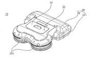
- FIG. 1is a perspective view of a robot cleaner according to an embodiment of the present invention.
- FIG 2is a bottom view of a robot cleaner according to an embodiment of the present invention.
- FIG 3is a front view of the robot cleaner according to the embodiment of the present invention.
- FIG. 4is a cross-sectional view and a partially enlarged view taken along line II-II ′ of FIG. 2.
- FIG. 5is a perspective view of the robot cleaner with the upper cover removed according to an embodiment of the present invention.
- FIG. 6is a view for explaining a rotary plate and a mop pad of a spinmab assembly of a robot cleaner according to one embodiment of the present invention
- FIG. 7is a perspective view showing the configuration of the spinmab assembly and the drive assembly of the robot cleaner according to an embodiment of the present invention.
- FIG. 8is a side view of the spinmab assembly and the drive assembly of the robot cleaner of FIG. 7.
- FIG. 9is a view for explaining the rotating plate and the collecting guide of the spinmab assembly according to an embodiment of the present invention.
- FIG. 10is a cross-sectional view taken along the line 'VIII' of FIG. 9.
- FIG. 11is a perspective view of another side of the spinmab assembly and the drive assembly of the robot cleaner of FIG. 7; FIG.
- FIG. 12is a view illustrating a robot cleaner in which a cleaning module and a coupler are removed according to an embodiment of the present invention.
- FIG. 13is a perspective view and a partially enlarged view for explaining one side of the module housing of FIG. 12.
- FIG. 14is a perspective view and a partially enlarged view for explaining the other side of the module housing of FIG.
- 15is a view showing a coupling state of the cleaning module, the module driving unit and the coupler according to an embodiment of the present invention.
- 16is a perspective view of the module driving unit according to an embodiment of the present invention.
- 17is a view showing a module driving unit in which the gear cabinet is removed according to an embodiment of the present invention.
- FIG. 18is a perspective view of a coupler according to an embodiment of the present invention.
- FIG. 19is a perspective view of a cleaning module according to an embodiment of the present invention.
- FIG. 20is a view showing a mop potting member of the cleaning module according to an embodiment of the present invention.
- 21is a view for explaining a method for mounting a rag cloth to the mop for tilting member of the cleaning module according to an embodiment of the present invention.
- 22is a view for explaining a method for mounting a mop cloth to the mop for tilting member of the cleaning module according to an embodiment of the present invention.
- FIG. 23is a view for explaining one embodiment of mounting the mop port tilting member of the cleaning module according to the embodiment of the present invention to the rotating member.
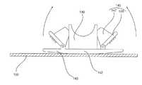
- FIG. 24is a view showing the arrangement of the cleaning module according to the movement of the robot cleaner according to an embodiment of the present invention, (a) is the arrangement of the cleaning module when the front of the robot cleaner, (b) is the rear of the robot cleaner Arrangement of cleaning module when driving.
- 1is a perspective view of a robot cleaner according to an embodiment of the present invention.
- 2is a bottom view of a robot cleaner according to an embodiment of the present invention.
- 3is a front view of the robot cleaner according to the embodiment of the present invention.
- 4is a cross-sectional view and a partially enlarged view taken along line IV-IV ′ of FIG. 2.
- 5is a perspective view of the robot cleaner with the upper cover removed according to an embodiment of the present invention.
- the robot cleaner 10includes a main body 20 forming an appearance; Moving means for moving the main body (30); A cleaning module 100 provided with at least a portion of the lower surface to be in contact with the bottom surface; And a module driving part 60 which adjusts an inclination angle formed by the bottom surface of the cleaning module to the bottom surface.
- the main body 20 of the mobile robotmay further include a drive motor for driving the movement means 30 therein and a controller (not shown) for controlling the movement means.
- the main body 20may further include a storage unit for storing water, a flow path for supplying water, a pump, and the like, according to the function of the robot cleaner.
- the main body 20may include a top cover that covers an upper portion to protect an internal configuration, and a base connected to the spinmab assembly 200 or the bumper 100, which is a configuration of the moving means.
- the moving means of the robot cleaneris a means for moving the main body 20 to travel, and may include a wheel, a rolling mop, or a spin mop, and in this embodiment, a spin mop assembly that rotates and mops in contact with the bottom surface ( 200 will be described as a moving means. However, this is not limited thereto and may be applied to a robot cleaner used as a moving means such as a wheel.
- the moving means according to the present embodimentincludes a spinmab assembly 200 rotating in contact with the bottom surface by mop pads disposed below and mopping, and a driving assembly 230 for rotating the spinmab assembly 200.
- the spinab assembly 200is inclined by a predetermined angle ⁇ based on the bottom surface.
- the entire surface of the spinab assembly 200is not evenly contacted with the bottom surface, but is inclined by a predetermined angle ⁇ so that the robot cleaner 10 is mainly contacted with a predetermined portion of the spinab.
- the spinmab assembly 200 according to the present embodimentmay be separately provided to perform a function of mopping the floor by receiving water from a water tank (not shown).
- the robot cleaner 10may include a plurality of spinab assemblies 200.
- the spinmab assembly 200is disposed below the main body 20.
- the spinmab assembly 200may move the main body 20 by rotation or wipe the floor.
- a reservoir 30 for storing water supplied to the spinab assembly 200 and a reservoir cover 32 for opening and closing an upper side of the reservoir 30may be disposed.
- the stock solution according to the present embodimentmay use water. However, this is one embodiment, it is also possible to use the stock solution as the cleaning liquid.
- the cleaning liquidrefers to a liquid mixed with a water and a cleaning agent for cleaning the wrong mouth on the bottom surface.
- the cleaning solutionis a means for removing through chemical reaction, and the cleaning agent used with water may use a detergent in the form of a powder or a liquid detergent.
- the robot cleaner 10includes a supply assembly 240 for supplying a stock solution to the spinmab assembly 200.
- Supply assembly 240supplies the stock solution to the mop pad of spinmab assembly 200.
- the supply assembly 240includes a reservoir 30 for storing a stock solution supplied to the spinmab assembly 200, and forms a flow path of the stock solution flowing between the reservoir 30 and the spinmab assembly 200. .
- the supply assemblyaccording to the present embodiment includes a pump 242 for supplying the stock solution stored in the reservoir 30 to the spinmab assembly 200, and a stock solution flowing between the reservoir 30 and the spinmab assembly 200.
- the hose 244may further include a flow path.
- Supply assembly 240may further include a valve 156 disposed on hose 244 to regulate the flow of the stock solution.
- the controller of the robot cleaner 10may adjust a pump for supplying the stock solution stored in the reservoir 30 to the spinmab assembly 200. That is, the controller adjusts the pump 242 to adjust the amount of the stock solution supplied to the spinmab assembly 200.
- the hose 244according to this embodiment is connected to the nozzle of the spinmab assembly 200.
- the hose 244supplies the stock solution to the sump guide of the spinmab assembly 200.
- the storage tank 30may be a sterilization module (not shown) for sterilizing the stock solution stored therein.
- the sterilization modulesterilizes the stock solution stored in the reservoir.
- FIG. 6is a view for explaining a rotary plate and a mop pad of a spinmab assembly of a robot cleaner according to one embodiment of the present invention
- FIG. 7is a perspective view showing the configuration of the spinmab assembly and the drive assembly of the robot cleaner according to an embodiment of the present invention.
- 8is a side view of the spinmab assembly and the drive assembly of the robot cleaner of FIG. 7.
- 9is a view for explaining the rotating plate and the collecting guide of the spinmab assembly according to an embodiment of the present invention.
- FIG. 10is a cross-sectional view taken along the line 'VIII' of FIG. 9.
- FIG. 11is a perspective view of another side of the spinmab assembly and the drive assembly of the robot cleaner of FIG. 7;
- FIG. 11is a perspective view of another side of the spinmab assembly and the drive assembly of the robot cleaner of FIG. 7;
- FIG. 11is a perspective view of another side of the spinmab assembly and the drive assembly of
- the spinmab assembly 200includes a rotating plate 204 connected to the driving assembly 230 and rotating; Mab pad 202 attached to the lower side of the rotating plate 204.
- Rotating plate 204may be provided with a binding means formed to be detachable detachable pad 202, a Velcro material may be used as the binding means.
- the spinmab assembly 200may be inclined to form a predetermined angle with the bottom surface.
- the spinmab assembly 200is connected to the rotating plate 204 to apply an elastic force to one side of the suspension base 210 and the suspension base 210 to adjust the inclination of the rotating plate 204 to adjust the inclination of the rotating plate 204.
- Suspension base 210is hinged to suspension frame 214 which is fixed to base 24 of main body 20.
- One side of the elastic member 212is fixed to the suspension frame 214 to apply an elastic force to the suspension base 210 connected to the other side. If there is no external force in the spinmab assembly 200, the rotating plate 204 of the spinmab is inclined to form a predetermined angle on the bottom surface by the elastic force of the elastic member 212.
- each spinab assembly 100 disposed on the left and right sides of the base by the elastic member 212 and the suspension base 210is disposed to be inclined on the bottom surface, and is formed to be symmetric with each other.
- the spinmab assembly 200includes a nozzle 220 connected to a hose 244 connected to the reservoir 30, and a collecting guide 222 to collect the stock solution supplied from the nozzle 220.
- the upper portion of the 204is formed with a rotating plate hole 224 formed to supply the stock solution collected in the collection guide 222 to the mother pad 202.
- the nozzle formed in the spinab assembly 200is connected to the hose 244 to receive the stock solution stored in the reservoir 30.
- the drive assembly 230rotates the rotor plate 204 of the spinmab assembly 200.
- One driving assembly 230 according to the present embodimentis disposed in each of the spinab assembly 200.
- the driving assembly 230is formed on the driving motor 232 and the rotation shaft 206 of the driving motor 232 for providing the driving force for rotating the spinab, and the first driving gear 234 and the first driving gear 234. And a second driving gear 236 engaged with the rotating plate 204 to transmit rotational force to the rotating plate 204.
- the first driving gear 234may be a worm gear that transmits rotational force to the second driving gear 236 disposed vertically.
- the second driving gear 236may be a gear that is engaged with the worm gear and receives a rotational force.
- the upper surface of the rotating plate 204is formed with a rotating shaft 206 protruding upward from the center, the upper end of the rotating shaft 206 is connected to the second drive gear 236.
- the drive assembly 230is disposed above the suspension base 210. Therefore, even if the inclination angle of the rotating plate 204 is changed, it is possible to stably drive the rotating plate 204.
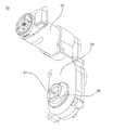
- FIG. 12is a view illustrating a robot cleaner in which a cleaning module and a coupler are removed according to an embodiment of the present invention.
- FIG. 13is a perspective view and a partially enlarged view for explaining one side of the module housing of FIG. 12.
- 14is a perspective view and a partially enlarged view for explaining the other side of the module housing of FIG.
- the main body 20 of the robot cleaner 10forms a module housing 40 for receiving the cleaning module 100 in contact with the floor.
- the module housing 40forms a space for accommodating a part of the cleaning module 100 and is opened downward.
- a rotating protrusion connecting member 60 for changing the angle of the cleaning module 100is disposed, and on the other side, a fixing protrusion insertion groove 42 for fixing the arrangement of the cleaning module 100 is formed. do.
- the module housing 40is formed by recessing a portion of the base 24 of the main body 20 inwardly.
- the module housing 40forms a space in which the rotating member 110 of the cleaning module 100 rotates.
- the module housing 40is divided into a circumferential surface 44 formed corresponding to the circumferential surface of the cleaning module 100 having a substantially cylindrical shape, and a pair of side portions 46 formed on a rotating shaft on which the cleaning module rotates. do.
- a fixing protrusion insertion groove 42 into which the fixing protrusion 120 of the cleaning module is insertedis formed at one surface 46a of the pair of side portions forming the module housing 40.
- the fixing protrusion insertion groove 42forms a space in which the fixing protrusion 120 formed at one side of the cleaning module 100 is disposed.
- the fixing protrusion insertion groove 42is opened at the lower side such that the fixing protrusion 120 of the cleaning module 100 is inserted or drawn out.
- the fixing protrusion insertion groove 42has a shape corresponding to the outer circumference formed by the fixing protrusion 120.
- the fixing protrusion insertion groove 42 according to the present embodimenthas a shape corresponding to the upper side of the fixing protrusion 120 having a polygonal pillar shape.
- the fixing protrusion insertion groove 42forms a space in which the coupler 70 to be described below is accommodated.
- the fixing protrusion insertion groove 42fixes the fixing protrusion 120 of the coupler 70 and the cleaning module 100.
- the fixing protrusion insertion groove 42is coupled to the coupler 70 to form a hole having a polygonal structure corresponding to the outer shape of the fixing protrusion 120.
- the other side 46b of the pair of side portions forming the module housing 40is provided with a rotary protrusion connecting member 60 connected to the rotary protrusion 130 of the cleaning module 100.
- the rotary protrusion connecting member 60is connected to the module driving motor 52 to be described below to change the inclination angle formed by the cleaning module 100 with the bottom surface.
- the rotary protrusion connecting member 60has a shape corresponding to the outer circumference formed by the rotary protrusion 130.
- Rotating projection connecting member 60is formed with a groove 61 of a shape that can accommodate the rotating projection (130).
- the rotary protrusion connecting member 60is fastened to the rotary protrusion 130 in such a manner that the rotary protrusion 130 is inserted.
- the groove 61 formed in the rotation protrusion connecting member 60has a shape corresponding to the polygonal structure formed by the rotation protrusion.
- 15is a view showing a coupling state of the cleaning module, the module driving unit and the coupler according to an embodiment of the present invention.
- 16is a perspective view of the module driving unit according to an embodiment of the present invention.
- 17is a view showing a module driving unit in which the gear cabinet is removed according to an embodiment of the present invention.
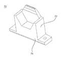
- 18is a perspective view of a coupler according to an embodiment of the present invention.
- the module driving unit 50drives the module driving motor 52 to change the angle of the cleaning module mounted inside the module housing.
- the module driving unit 50includes a module driving motor 52 that rotates with an external power source, a rotating protrusion connecting member 60 that rotates the cleaning module 100 by rotating the module driving motor, and a rotating protrusion of the module driving motor. At least one gear for transmitting to the connecting member 60.
- the module driving unit 50includes a plurality of gears 54, 55, 56, and 57 transmitting the rotational force of the module driving motor 52 to the rotary protrusion connecting member 60.
- the module driving unit 50 according to the present embodimentincludes a first gear 54 coupled to a rotation shaft of the module driving motor, a second gear 55 rotating in engagement with the first gear 54, and a first gear 54.
- the second gear 55includes a third gear 56 that rotates in engagement with the second gear 55 and a fourth gear 57 that rotates in engagement with the third gear 56 to rotate the rotation protrusion connecting member 60.
- the plurality of gears according to the present embodimentmay use a spur gear having a thread formed on a circumferential surface thereof in a cylindrical shape.
- the number and shape of the gears as described aboveis one embodiment, it is possible to deform within the scope to perform the function of transmitting the rotational force of the module driving motor 52 to the rotation projection (130).
- the rotary shaft 58 of the fourth gear 57 according to the present embodimentis connected to the rotary projection connecting member 60 so that when the fourth gear 57 rotates, the rotary projection connecting member 60 also rotates together. .
- the rotary projection connecting member 60is connected to the rotary shaft 58 of the fourth gear 57 and rotates together with the fourth gear 57.
- the rotary protrusion connecting member 60forms a groove 61 for receiving the rotary protrusion 130 of the cleaning module to be described below.
- the groove 61 formed in the rotary protrusion connecting member 60has a shape corresponding to the outer circumference of the rotary protrusion 130.
- the module driving unit 50includes a gear cabinet 59 surrounding the plurality of gears 54, 55, 56, and 57.
- a plurality of gears 54, 55, 56, 57are disposed inside the gear cabinet 59.
- the rotary protrusion connecting memberis disposed outside the gear cabinet 59, and a plurality of bearings are disposed between the gear cabinet 59 and the rotary protrusion connecting member 60 for smooth rotation.
- the robot cleaner 10further includes a coupler 70 inserted into the fixing protrusion insertion groove 42 to fix the fixing protrusion 120.
- the coupler 70contacts the lower side of the fixing protrusion 120 and the distal end of the fixing protrusion 120.
- the couplerfixes the fixing protrusion 120 together with the fixing protrusion insertion groove 42.
- the coupler 70includes a fixing protrusion coupling portion 72 disposed to be in contact with a lower side of the fixing protrusion 120 and an insertion groove fastening portion 74 fastened to the fixing protrusion insertion groove.
- the insertion groove fastening portion 74may be fastened to the fixing protrusion insertion groove 42 by a fastening means such as a bolt.
- the fixing protrusion coupling portion 72has a shape corresponding to the lower side of the outer circumference of the fixing protrusion 120.
- the fixing protrusion insertion groove 42 and the coupler according to the present embodimentform a groove into which the fixing protrusion 120 of the hexagonal pillar shape is inserted.
- 19is a perspective view of a cleaning module according to an embodiment of the present invention.
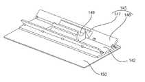
- 20is a view showing a mop potting member of the cleaning module according to an embodiment of the present invention.
- 21is a view for explaining a method for mounting a rag cloth to the mop for tilting member of the cleaning module according to an embodiment of the present invention.
- 22is a view for explaining a method for mounting a mop cloth to the mop for tilting member of the cleaning module according to an embodiment of the present invention.
- FIG. 23is a view for explaining one embodiment of mounting the mop port tilting member of the cleaning module according to the embodiment of the present invention to the rotating member.
- 24is a view showing the arrangement of the cleaning module according to the movement of the robot cleaner according to an embodiment of the present invention.
- the cleaning module 100may mop the floor when the robot cleaner 10 moves.
- the cleaning module 100 according to the present embodimentforms an inclination angle with the bottom surface such that a part thereof contacts the bottom surface.
- the cleaning module 100has a different inclination angle formed from the bottom surface of the module driving unit.
- the cleaning module 100is detachably arranged in the module housing 40.
- the cleaning module 100is connected to the mop tilting member 140 and the rotating protrusion 130 to fix the mop for cleaning the floor.
- the rotating member 110to adjust the inclination of the mop tilting member 140 and the rotating member 110.
- Rotating protrusion 130is disposed on one side and connected to the module driving unit 50, and a fixing protrusion 120 is disposed on the other side of the rotating member 110 to support the rotation of the rotating member 110.
- the rotating member 110has a cylindrical shape. Rotating member 110 is coupled to the mab tilting member 140 on one side of the circumferential surface. Rotating member 110 is formed on one side of the circumferential surface of the coupling groove 112 is inserted into the end of the coupling portion 149 of the Mab tilting member 140 to be described below. Coupling groove 112 has a shape corresponding to the end of the coupling portion 149.
- Rotating member 110has a Mab tilting member 140 is connected to one side of the circumferential surface, the rotation projection 130 is disposed on one side except the circumferential surface, the fixing projection 120 is disposed on the other side.
- a circumferential surface of the pivot member 110is formed with a coupling groove for inserting and fixing an end of the mab tilting member 140.
- the fixing protrusion 120is disposed on the axis on which the rotating member 110 rotates. Fixing protrusion 120 is connected to the rotating member 110 and the bearing does not restrain the rotation of the rotating member (110).
- the outer circumference of the fixing protrusion 120has a polygonal shape.
- the outer circumference of the fixing protrusion 120is surrounded by the fixing protrusion insertion groove 42 and the coupler 70.
- the fixing protrusion 120is fixed to the outer circumference of the fixing protrusion insertion groove 42 and the coupler 70.
- the fixing protrusion 120 according to the present embodimenthas an outer circumference having a hexagonal pillar shape, which is one embodiment, and various changes in the range in which the fixing protrusion 120 can be fixed in the module housing are provided. It is possible.
- the rotating protrusion 130transmits the rotational force of the module driving unit 50 to the rotating member 110. Therefore, when the rotary protrusion connecting member 60 connected to the module driving unit rotates, the rotary protrusion 130 rotates together with the rotating member 110.
- the outer circumference of the rotary protrusion 130has a polygonal shape.
- the rotary protrusion 130is inserted into the groove 61 formed at the outer protrusion connecting member 60.
- Rotating projection according to the present embodimenthas an outer circumference has a square pillar shape, which is one embodiment, it is possible in a variety of changes in the range that can be fixed to the groove formed in the rotating projection connecting member.
- the cleaning module 100may mop the bottom surface by arranging the mab tilting member 140 in an inclined direction of the robot cleaner by the rotation of the rotation member 110.
- Mab tilting member 140is attached to the tilting plate to mop the bottom surface using a fixed Mab 150.
- Mab 150 attached to the mab tilting member 140may use a disposable cloth or a general cloth cloth.
- Mab tilting member 140is a tilting plate 142 to which the Mab 150 is attached, protrudes from one side of the Mab fixing unit 145 and the tilting plate 142 to fix the Mab to the tilting plate 142 and tilting plate 142 ) Is coupled to the rotating member 110.
- the tilting plate 142has a plate shape, and one side of the tilting plate 142 is attached. One side of the tilting plate 142 is arranged with a mop for mopping the bottom, the other side is arranged a mop fixing part 145 for fixing the mop. Mab surrounds one surface of the tilting plate 142 and is fixed at the other surface of the tilting plate 142. The other side of the tilting plate is disposed a coupling portion 149 for connecting the tilting plate 142 and the rotating member 110.
- the tilting plate 142forms a curved portion 143 on which one surface on which the mop is disposed is convex toward the outside of the tilting plate 142.
- a pair of mop fixing parts 145 fixing the mop 150 disposed on one surface of the tilting plate 142is disposed.
- Mop fixing part 145is hinged to the other side of the tilting plate.
- the pair of non-fixed fixing parts 145are disposed at both ends of the other surface of the tilting plate.
- the mop fixing part 145is divided into a mop fixing plate 146 hinged to the tilting plate, and a handle 147 for lifting the mop fixing plate based on the hinge axis. In the state where a separate pressure is not applied to the handle portion, the fixing plate 146 abuts the tilting plate.
- Mab 150is partially fixed between the Mab fixing plate 146 and the tilting plate 142. Referring to FIGS. 21 to 22, the user applies force to the handle to separate the mop plate 146 from the tilting plate, and then places the mop between the tilting plate 142 and the mop plate 146. 150 is fixed to the tilting plate 142.
- the coupling part 149protrudes from the other surface of the tilting plate 142.
- Coupling portion 149is connected to the circumferential surface of the rotating member (110).
- Coupling portion 149is inserted into the coupling groove 112 formed at one end of the rotating member.
- the end of the coupling portion 149has a shape in which the center is concave, and both ends protrude.
- Coupling groove 112 formed on one side of the rotating member 110has a shape corresponding to the end of the coupling portion 149.
- the shape of the end portion of the coupling portion 149may be variously modified in a range of performing a function of fixing the mab tilting member 140 to the pivot member 110.
- Coupling portion 149may be a fastening protrusion (not shown) to be fixed to the coupling groove 112 of the rotating member 110 on one side or both sides.
- the fastening protrusionis fitted into a fastening groove (not shown) formed in the coupling groove of the rotating member.
- the end of the engaging portionis engaged with the rotating member in such a manner that the fastening protrusion is fitted into the engaging groove of the rotating member.
- Mab tilting memberis a tilt angle formed by the bottom surface and the tilting plate by the operation of the module driving unit.
- Mab tilting member 140can adjust the surface facing the tilting plate 142 corresponding to the moving direction of the robot cleaner 10.
- the Mab tilting member 140 according to an embodiment of the present inventioncan adjust the angle formed by the tilting plate 142 and the bottom surface in response to the moving speed of the robot cleaner.
- the mop tilting member 140 of the robot cleaner 10may have the tilting plate 142 facing the bottom surface of the robot cleaner 10 in a direction opposite to that of the robot cleaner 10.
- the module driving motor 52can be operated to be arranged.
- the mab tilting member 140 according to the present exemplary embodimentis disposed so that one surface of the tilting plate faces backward and forms an inclination angle with the bottom surface.
- the mab tilting member 140 according to the present embodimenthas one side of the tilting plate 142 facing forward and the inclined angle of the bottom surface. Arranged to achieve.
- Mab tilting member 140can operate the module driving motor 52 to adjust the inclination angle formed by the bottom surface and the tilting plate.
- Mab tilting member 140 according to an embodiment of the present inventioncan adjust the tilt angle of the tilting plate 142 in consideration of the moving speed of the robot cleaner 10, the material of the bottom surface.
Landscapes
- Engineering & Computer Science (AREA)
- Mechanical Engineering (AREA)
- Robotics (AREA)
- Physics & Mathematics (AREA)
- Radar, Positioning & Navigation (AREA)
- Aviation & Aerospace Engineering (AREA)
- Remote Sensing (AREA)
- General Physics & Mathematics (AREA)
- Automation & Control Theory (AREA)
- General Chemical & Material Sciences (AREA)
- Chemical Kinetics & Catalysis (AREA)
- Plasma & Fusion (AREA)
- Chemical & Material Sciences (AREA)
- Nozzles For Electric Vacuum Cleaners (AREA)
- Electric Vacuum Cleaner (AREA)
Abstract
Description
Translated fromKorean본 발명은 로봇 청소기에 관한 것으로, 더욱 상세하게는, 청소모듈이 탈부착되는 로봇 청소기에 관한 것이다.The present invention relates to a robot cleaner, and more particularly, to a robot cleaner to which the cleaning module is attached and detached.
최근 가정 내에서의 로봇 사용이 점차 확대되고 있는 추세이다. 이러한 가정용 로봇의 대표적인 예는 로봇 청소기이다. 로봇 청소기는 이동형 로봇으로서 일정 영역을 스스로 주행하며 바닥에 쌓인 먼지 등의 이물질을 흡입함으로써 청소 공간을 자동으로 청소하는 하거나, 회전맙을 이용하여 이동함과 동시에 회전맙으로 바닥을 닦는 방식으로 청소할 수 있다.Recently, the use of robots in the home is gradually increasing. A representative example of such a home robot is a robot cleaner. The robot cleaner is a mobile robot that runs on a certain area by itself and inhales foreign substances such as dust accumulated on the floor to clean the cleaning space automatically, or it can be moved by using the rotary mop and at the same time by wiping the floor with the rotary mop. have.
한국공개특허 10-2015-0018968호는 회전맙을 이용한 로봇 청소기를 개시하고 있다. 다만, 이러한 회전맙을 이용한 청소기는 물을 이용한 걸레질을 하는 형식으로 물기를 닦아내는 방식의 걸레질을 구현할 수 없는 문제가 있다.Korean Laid-Open Patent Publication No. 10-2015-0018968 discloses a robot cleaner using a rotary mop. However, there is a problem in that the cleaner using the rotary Mab can not implement the mop of the method of wiping the water in the form of mopping using water.
본 발명이 해결하고자 하는 과제는 바닥을 닦아내는 방식으로 청소를 수행하는 로봇 청소기를 제공하는 것이다.The problem to be solved by the present invention is to provide a robot cleaner to perform the cleaning by wiping the floor.
본 발명이 해결하고자 하는 다른 과제는 로봇 청소기의 이동방향에 따라 효율적으로 걸레질하는 로봇 청소기를 제공하는 것이다.Another problem to be solved by the present invention is to provide a robot cleaner to mop efficiently according to the moving direction of the robot cleaner.
본 발명이 해결하고자 하는 또 다른 과제는 교체가 용이한 청소모듈이 장착되는 로봇 청소기를 제공하는 것이다.Another object of the present invention is to provide a robot cleaner equipped with a cleaning module that is easy to replace.
본 발명이 해결하고자 하는 또 다른 과제는 로봇청소기의 1회 주행으로 바닥면에 두가지 방법의 청소를 수행할 수 있는 이동로봇을 제공하는 것이다.Another problem to be solved by the present invention is to provide a mobile robot that can perform the cleaning of the two methods on the floor surface in one run of the robot cleaner.
본 발명의 과제들은 이상에서 언급한 과제들로 제한되지 않으며, 언급되지 않은 또 다른 과제들은 아래의 기재로부터 당업자에게 명확하게 이해될 수 있을 것이다.The objects of the present invention are not limited to the above-mentioned objects, and other objects that are not mentioned will be clearly understood by those skilled in the art from the following description.
상기의 과제를 해결하기 위한 수단으로 본 발명에 따른 로봇 청소기는 외형을 형성하는 메인바디; 상기 메인바디를 이동시키는 이동수단; 바닥면에 하측면의 적어도 일부가 접촉 가능하게 구비되는 청소모듈; 및 상기 청소모듈의 하측면이 상기 바닥면과 형성하는 경사각을 조절하는 모듈구동부를 포함하여, 로봇 청소기의 청소모듈의 하측면이 바닥면과 이루는 각도를 조절하여 바닥면을 청소할 수 있다.As a means for solving the above problems, the robot cleaner according to the present invention comprises a main body to form an appearance; Moving means for moving the main body; A cleaning module provided with at least a portion of the lower surface to be in contact with the bottom surface; And a module driver configured to adjust an inclination angle formed by the lower side of the cleaning module to the bottom surface, and clean the bottom surface by adjusting an angle at which the bottom side of the cleaning module of the robot cleaner forms the bottom surface.
상기의 과제를 해결하기 위한 수단으로 본 발명에 따른 로봇 청소기의 상기 맙틸팅부재는, 맙이 부착되는 틸팅판; 상기 틸팅판에 맙을 고정하는 맙고정부; 및 틸팅판의 일측에서 돌출되어 회동부재와 연결되는 회동부재 연결부를 포함하고, 상기 틸팅판은 바닥면을 향하는 일면이 외측으로 볼록한 곡면부를 형성하여, 맙틸팅부재의 틸팅판의 각도를 변경하며 바닥면을 걸레질 할 수 있다.The Mab tilting member of the robot cleaner according to the present invention as a means for solving the above problems, the tilting plate is attached Mab; Mop fixation for fixing the mop to the tilting plate; And a pivot member connecting portion protruding from one side of the tilting plate and connected to the pivoting member, wherein the tilting plate forms a curved surface with one surface facing outwardly convex to change the angle of the tilting plate of the mop tilting member. You can mop the noodles.
상기의 과제를 해결하기 위한 수단으로 본 발명에 따른 로봇 청소기의 상기 청소모듈은, 상기 회동부재의 일측에 배치되고, 상기 모듈구동부와 연결되는 회전돌기; 및 상기 회동부재의 타측에 배치되고, 상기 회동부재의 회전을 지지하는 고정돌기를 포함하고, 상기 청소모듈을 상기 메인바디의 일측에 고정시키는 커플러를 포함하며, 상기 메인바디는 상기 청소모듈의 일부를 수용하도록 내측으로 공간을 형성하는 모듈하우징을 형성하고, 상기 모듈하우징의 일측에는 상기 고정돌기가 삽입되는 고정돌기 삽입홈이 형성되고, 상기 고정돌기 하우징과 상기 커플러는 상기 회동부재의 타측에 배치된 상기 고정돌기를 고정하여, 청소모듈을 메인바디에서 탈착가능하게 배치할 수 있다.The cleaning module of the robot cleaner according to the present invention as a means for solving the above problems, is disposed on one side of the rotating member, the rotary projection connected to the module driving unit; And a fixing protrusion disposed on the other side of the rotating member and supporting the rotation of the rotating member, the coupler fixing the cleaning module to one side of the main body, wherein the main body is part of the cleaning module. A module housing is formed to form a space inwardly to accommodate the second housing, and a fixing protrusion insertion groove into which the fixing protrusion is inserted is formed at one side of the module housing, and the fixing protrusion housing and the coupler are disposed at the other side of the pivot member. By fixing the fixing projections, it is possible to arrange the cleaning module detachably from the main body.
상기의 과제를 해결하기 위한 수단으로 본 발명에 따른 로봇 청소기는 이동수단은, 하측에 배치된 맙 패드로 바닥면과 접촉하여 회전하며 걸레질하는 스핀맙 어셈블리; 및 상기 스핀맙 어셈블리를 회전시키는 구동 어셈블리를 포함하고, 상기 스핀맙 어셈블리에 저장액을 공급하는 공급 어셈블리를 더 포함하여, 스핀맙 어셈블리로 바닥을 물걸레 청소하고, 청소모듈로 바닥의 물기를 닦아낼 수 있다.As a means for solving the above problems, the robot cleaner according to the present invention, the moving means, spin mop assembly for rotating and mopping in contact with the bottom surface with a Mab pad disposed on the lower side; And a drive assembly for rotating the spinmab assembly, and further comprising a supply assembly for supplying a stock solution to the spinmab assembly, mopping the floor with the spinmab assembly, and mopping the floor with the cleaning module. Can be.
첫째, 본 발명에 따른 로봇 청소기는 청소모듈; 및 상기 청소모듈의 하측면이 상기 바닥면과 형성하는 경사각을 조절하는 모듈구동부를 포함하여, 청소공간 또는 청소방식에 따라 청소모듈의 하측면이 바닥면과 형성하는 경사각을 조절하여, 바닥을 닦아내는 방식으로 청소를 할 수 있는 장점이 있다.First, the robot cleaner according to the present invention comprises a cleaning module; And a module driver configured to adjust the inclination angle formed by the lower side of the cleaning module to the bottom surface, and adjust the inclination angle formed by the lower side of the cleaning module to the bottom surface according to a cleaning space or a cleaning method to wipe off the floor. There is an advantage that can be cleaned in a way.
둘째, 본 발명에 따른 로봇 청소기는 청소모듈의 바닥면과 접촉하는 틸팅판이 곡면을 형성하여 틸팅판의 조절이 용이하고, 이러한 틸팅판을 조절하여, 로봇 청소기의 이동방향에 따라 틸팅판의 각도를 변경하여 바닥을 효과적으로 닦아낼 수 있는 장점이 있다.Second, in the robot cleaner according to the present invention, the tilting plate in contact with the bottom surface of the cleaning module forms a curved surface to easily adjust the tilting plate, and by adjusting the tilting plate, the angle of the tilting plate according to the moving direction of the robot cleaner is adjusted. The advantage is that you can effectively wipe the floor by changing it.
셋째, 본 발명에 따른 로봇 청소기는 모듈구동부로 회전하는 청소모듈을 메인바디에 탈착가능한 구조를 형성하고, 청소모듈을 탈착하는데 있어서 사용자에게 사용의 편의를 제공하는 장점이 있다.Third, the robot cleaner according to the present invention has a structure in which a cleaning module that is rotated by the module driving unit is detachable from the main body and provides a user with convenience in removing the cleaning module.
넷째, 본 발명에 따른 로봇 청소기는 이동수단을 물걸레 청소하는 스핀맙 어셈블리를 사용하여, 스핀맙 어셈블리로 바닥면을 물걸레질 하고, 청소모듈로 바닥면의 물기를 닦아내어, 1회의 주행으로 물걸레질과 마른 걸레질을 동시에 수행할 수 있는 장점이 있다.Fourthly, the robot cleaner according to the present invention uses a spinab assembly for cleaning a mop by using a spin mop assembly, and mops the bottom surface with a spin mop assembly, and wipes off the moisture on the bottom surface with a cleaning module, and mops with one run. There is an advantage that can be carried out and dry mop at the same time.
도 1은 본 발명의 일 실시예에 따른 로봇 청소기의 사시도이다.1 is a perspective view of a robot cleaner according to an embodiment of the present invention.
도 2는 본 발명의 일 실시예에 따른 로봇 청소기의 저면도이다.2 is a bottom view of a robot cleaner according to an embodiment of the present invention.
도 3은 본 발명의 일 실시예에 따른 로봇 청소기의 정면도이다.3 is a front view of the robot cleaner according to the embodiment of the present invention.
도 4는 도 2의 Ⅱ-Ⅱ’을 자른 단면도와 부분확대도이다.4 is a cross-sectional view and a partially enlarged view taken along line II-II ′ of FIG. 2.
도 5는 본 발명의 일 실시예에 따른 상부커버가 제거된 로봇 청소기의 사시도이다.5 is a perspective view of the robot cleaner with the upper cover removed according to an embodiment of the present invention.
도 6는 본 발명의 하나의 실시예에 의한 로봇 청소기의 스핀맙 어셈블리의 회전판과 맙패드를 설명하기 위한 도면이다.FIG. 6 is a view for explaining a rotary plate and a mop pad of a spinmab assembly of a robot cleaner according to one embodiment of the present invention; FIG.
도 7은 본 발명의 하나의 실시예에 의한 로봇 청소기의 스핀맙 어셈블리와 구동 어셈블리의 구성을 도시한 사시도이다.7 is a perspective view showing the configuration of the spinmab assembly and the drive assembly of the robot cleaner according to an embodiment of the present invention.
도 8은 도 7의 로봇 청소기의 스핀맙 어셈블리와 구동 어셈블리의 측면도이다.8 is a side view of the spinmab assembly and the drive assembly of the robot cleaner of FIG. 7.
도 9은 본 발명의 하나의 실시예에 의한 스핀맙 어셈블리의 회전판과 집수 가이드를 설명하기 위한 도면이다.9 is a view for explaining the rotating plate and the collecting guide of the spinmab assembly according to an embodiment of the present invention.
도 10는 도 9의 Ⅹ-Ⅹ’부분을 자른 단면도이다.FIG. 10 is a cross-sectional view taken along the line 'VIII' of FIG. 9.
도 11은 도 7의 로봇 청소기의 스핀맙 어셈블리와 구동 어셈블리의 다른 측면에서 본 사시도이다.FIG. 11 is a perspective view of another side of the spinmab assembly and the drive assembly of the robot cleaner of FIG. 7; FIG.
도 12는 본 발명의 실시예에 따른 청소모듈과 커플러가 제거된 로봇 청소기를 도시한 도면이다.12 is a view illustrating a robot cleaner in which a cleaning module and a coupler are removed according to an embodiment of the present invention.
도 13은 도 12의 모듈하우징의 일측을 설명하기 위한 사시도와 부분확대도이다.FIG. 13 is a perspective view and a partially enlarged view for explaining one side of the module housing of FIG. 12.
도 14는 도 12의 모듈하우징의 타측을 설명하기 위한 사시도와 부분확대도이다.14 is a perspective view and a partially enlarged view for explaining the other side of the module housing of FIG.
도 15는 본 발명의 일 실시예에 따른 청소모듈, 모듈구동부 및 커플러의 결합상태를 도시한 도면이다.15 is a view showing a coupling state of the cleaning module, the module driving unit and the coupler according to an embodiment of the present invention.
도 16은 본 발명의 일 실시예에 따른 모듈구동부의 사시도이다.16 is a perspective view of the module driving unit according to an embodiment of the present invention.
도 17은 본 발명의 일 실시예에 따른 기어캐비닛이 제거된 모듈구동부를 도시한 도면이다.17 is a view showing a module driving unit in which the gear cabinet is removed according to an embodiment of the present invention.
도 18는 본 발명의 일 실시예에 따른 커플러의 사시도이다.18 is a perspective view of a coupler according to an embodiment of the present invention.
도 19는 본 발명의 일 실시예에 따른 청소모듈의 사시도이다.19 is a perspective view of a cleaning module according to an embodiment of the present invention.
도 20은 본 발명의 일 실시예에 따른 청소모듈의 걸레포틸팅부재를 도시한 도며이다.20 is a view showing a mop potting member of the cleaning module according to an embodiment of the present invention.
도 21은 본 발명의 일 실시예에 따른 청소모듈의 걸레포틸팅부재에 걸레포를 장착하는 방법을 설명하기 위한 도면이다.21 is a view for explaining a method for mounting a rag cloth to the mop for tilting member of the cleaning module according to an embodiment of the present invention.
도 22는 본 발명의 일 실시예에 따른 청소모듈의 걸레포틸팅부재에 걸레포를 장착하는 방법을 설명하기 위한 도면이다.22 is a view for explaining a method for mounting a mop cloth to the mop for tilting member of the cleaning module according to an embodiment of the present invention.
도 23는 본 발명의 일 실시예에 따른 청소모듈의 걸레포틸팅부재를 회동부재에 장착하는 하나의 실시예를 설명하기 위한 도면이다.FIG. 23 is a view for explaining one embodiment of mounting the mop port tilting member of the cleaning module according to the embodiment of the present invention to the rotating member.
도 24는 본 발명의 일 실시예에 따른 로봇 청소기의 이동에 따른 청소모듈의 배치를 도시한 도면으로, (a)는 로봇 청소기의 전방주행시 청소모듈의 배치이고, (b)는 로봇 청소기의 후방주행시 청소모듈의 배치이다.24 is a view showing the arrangement of the cleaning module according to the movement of the robot cleaner according to an embodiment of the present invention, (a) is the arrangement of the cleaning module when the front of the robot cleaner, (b) is the rear of the robot cleaner Arrangement of cleaning module when driving.
본 발명의 이점 및 특징, 그리고 그것들을 달성하는 방법은 첨부되는 도면과 함께 상세하게 후술되어 있는 실시예를 참조하면 명확해질 것이다. 그러나 본 발명은 이하에서 개시되는 실시예에 한정되는 것이 아니라 서로 다른 다양한 형태로 구현될 수 있으며, 단지 본 실시예는 본 발명의 개시가 완전하도록 하고, 본 발명이 속하는 기술분야에서 통상의 지식을 가진 자에게 발명의 범주를 완전하게 알려주기 위해 제공되는 것이며, 본 발명은 청구항의 범주에 의해 정의될 뿐이다. 명세서 전체에 걸쳐 동일 참조 부호는 동일 구성 요소를 지칭한다.Advantages and features of the present invention, and methods for achieving them will become apparent with reference to the embodiments described below in detail in conjunction with the accompanying drawings. However, the present invention is not limited to the embodiments disclosed below, but may be implemented in various forms, and only the present embodiments are intended to complete the disclosure of the present invention, and the general knowledge in the art to which the present invention pertains. It is provided to fully convey the scope of the invention to those skilled in the art, and the present invention is defined only by the scope of the claims. Like reference numerals refer to like elements throughout.
이하, 본 발명의 실시예들에 따른 이동 로봇을 도면들을 참고하여 설명하도록 한다.Hereinafter, a mobile robot according to embodiments of the present invention will be described with reference to the drawings.
도 1은 본 발명의 일 실시예에 따른 로봇 청소기의 사시도이다. 도 2는 본 발명의 일 실시예에 따른 로봇 청소기의 저면도이다. 도 3은 본 발명의 일 실시예에 따른 로봇 청소기의 정면도이다. 도 4는 도 2의 Ⅳ-Ⅳ’을 자른 단면도와 부분확대도이다. 도 5는 본 발명의 일 실시예에 따른 상부커버가 제거된 로봇 청소기의 사시도이다.1 is a perspective view of a robot cleaner according to an embodiment of the present invention. 2 is a bottom view of a robot cleaner according to an embodiment of the present invention. 3 is a front view of the robot cleaner according to the embodiment of the present invention. 4 is a cross-sectional view and a partially enlarged view taken along line IV-IV ′ of FIG. 2. 5 is a perspective view of the robot cleaner with the upper cover removed according to an embodiment of the present invention.
이하에서는 도 1 내지 도 7을 참조하여, 본 실시예에 따른 로봇청소기의 전체적인 구성을 설명한다.Hereinafter, the overall configuration of the robot cleaner according to the present embodiment will be described with reference to FIGS. 1 to 7.
본 실시예에 따른 로봇 청소기(10)는 외형을 형성하는 메인바디(20); 상기 메인바디를 이동시키는 이동수단(30); 바닥면에 하측면의 적어도 일부가 접촉 가능하게 구비되는 청소모듈(100); 및 상기 청소모듈의 하측면이 상기 바닥면과 형성하는 경사각을 조절하는 모듈구동부(60)를 포함한다.The robot cleaner 10 according to the present embodiment includes a
본 실시예에 따른 이동 로봇의 메인바디(20)는 내부에 이동수단(30)을 구동하는 구동모터, 이동수단을 제어하는 제어부(미도시)를 더 포함할 수 있다. 또한, 메인바디(20)의 내부에는 로봇 청소기의 기능에 따라, 물을 저장하는 저장부, 물을 공급하는 유로 및 펌프 등을 더 포함할 수 있다. 메인바디(20)는 내부 구성을 보호하도록 상부를 커버하는 상부커버와, 이동수단의 구성인 스핀맙 어셈블리(200)이나 범퍼(100)와 연결되는 베이스로 구성될 수 있다.The
로봇 청소기의 이동수단은 메인바디(20)를 주행하기 위해 이동시키는 수단으로, 휠, 롤링맙 또는 스핀맙을 포함할 수 있으며, 본 실시예에서는 바닥면과 접촉하여 회전하며 걸레질하는 스핀맙 어셈블리(200)를 이동수단으로 설명한다. 다만, 이는 하나의 실시예로써, 이에 한정되지 않고, 바퀴 등의 이동수단으로 사용하는 로봇 청소기에도 적용될 수 있다. 본 실시예에 따른 이동수단은 하측에 배치된 맙 패드로 바닥면과 접촉하여 회전하며 걸레질하는 스핀맙 어셈블리(200), 스핀맙 어셈블리(200)를 회전시키는 구동 어셈블리(230)를 포함한다.The moving means of the robot cleaner is a means for moving the
도 3를 참조하면, 본 실시예에 따른 로봇 청소기(10)는 스핀맙 어셈블리(200)가 바닥면을 기준으로 일정각도(θ)만큼 기울어져 배치된다. 로봇 청소기(10)의 이동이 원활하도록, 스핀맙 어셈블리(200)의 전체면에서 고르게 바닥면과 맞닿지 않고, 일정각도(θ)만큼 기울어져 스핀맙의 일정부분에서 주로 맞닿도록 배치된다. 본 실시예에 따른 스핀맙 어셈블리(200)는 별도로 마련되 수조(미도시)로부터 물을 공급받아 바닥을 물걸레질하는 기능을 수행하는 것도 가능하다.Referring to FIG. 3, in the
로봇 청소기(10)는 복수개의 스핀맙 어셈블리(200)를 포함할 수 있다. 스핀맙 어셈블리(200)는 메인바디(20)의 하측에 배치된다. 스핀맙 어셈블리(200)는 회전으로 메인바디(20)를 이동시키거나, 바닥을 닦을 수 있다.The
메인바디(20) 내부에는 스핀맙 어셈블리(200)에 공급되는 물을 저장하는 저장조(30)와 저장조(30)의 상측을 개폐하는 저장조 커버(32)가 배치될 수 있다.Inside the
본 실시예에 따른 저장액은 물을 사용할 수 있다. 다만, 이는 하나의 실시예로써, 저장액을 세정액으로 사용하는 것도 가능하다. 세정액은 바닥면에 묻은 오구를 세척하는 물과 세정제가 혼합된 액체를 의미한다. 세정액은 화학작용을 통해 제거하는 수단으로써, 물과 함께 사용되는 세정제는 분말형태의 세제 또는 액상의 세제액을 사용할 수 있다.The stock solution according to the present embodiment may use water. However, this is one embodiment, it is also possible to use the stock solution as the cleaning liquid. The cleaning liquid refers to a liquid mixed with a water and a cleaning agent for cleaning the wrong mouth on the bottom surface. The cleaning solution is a means for removing through chemical reaction, and the cleaning agent used with water may use a detergent in the form of a powder or a liquid detergent.
로봇 청소기(10)은 스핀맙 어셈블리(200)에 저장액을 공급하는 공급 어셈블리(240)를 포함한다. 공급 어셈블리(240)는 스핀맙 어셈블리(200)의 맙패드에 저장액을 공급한다.The
공급 어셈블리(240)는 스핀맙 어셈블리(200)에 공급되는 저장액을 저장하는 저장조(30)를 포함하고, 저장조(30)와 스핀맙 어셈블리(200) 사이에서 유동하는 저장액의 유로를 형성한다. 본 실시예에 따른 공급 어셈블리는 저장조(30)에 저장된 저장액을 스핀맙 어셈블리(200)로 공급하는 펌프(242)와, 저장조(30)와 스핀맙 어셈블리(200) 사이에서 유동하는 저장액의 유로를 형성하는 호스(244)를 더 포함할 수 있다. 공급 어셈블리(240)는 저장액의 유동을 조절하도록 호스(244) 상에 배치된 밸브(156)를 더 포함할 수 있다. 본 실시예에 따른 로봇청소기(10)의 제어부는 저장조(30)에 저장된 저장액을 스핀맙 어셈블리(200)로 공급하는 펌프를 조절할 수 있다. 즉, 제어부는 펌프(242)를 조절하여, 스핀맙 어셈블리(200)로 공급되는 저장액의 량을 조절한다.The
본 실시예에 따른 호스(244)는 스핀맙 어셈블리(200)의 노즐로 연결된다. 호스(244)는 스핀맙 어셈블리(200)의 집수가이드로 저장액을 공급한다.The
저장조(30)에는 내부에 저장된 저장액을 살균하는 살균모듈(미도시)이 배치될 수 있다. 살균모듈은 저장조에 저장된 저장액을 살균한다.The
도 6는 본 발명의 하나의 실시예에 의한 로봇 청소기의 스핀맙 어셈블리의 회전판과 맙패드를 설명하기 위한 도면이다. 도 7은 본 발명의 하나의 실시예에 의한 로봇 청소기의 스핀맙 어셈블리와 구동 어셈블리의 구성을 도시한 사시도이다. 도 8은 도 7의 로봇 청소기의 스핀맙 어셈블리와 구동 어셈블리의 측면도이다. 도 9은 본 발명의 하나의 실시예에 의한 스핀맙 어셈블리의 회전판과 집수 가이드를 설명하기 위한 도면이다. 도 10는 도 9의 Ⅹ-Ⅹ’부분을 자른 단면도이다. 도 11은 도 7의 로봇 청소기의 스핀맙 어셈블리와 구동 어셈블리의 다른 측면에서 본 사시도이다.FIG. 6 is a view for explaining a rotary plate and a mop pad of a spinmab assembly of a robot cleaner according to one embodiment of the present invention; FIG. 7 is a perspective view showing the configuration of the spinmab assembly and the drive assembly of the robot cleaner according to an embodiment of the present invention. 8 is a side view of the spinmab assembly and the drive assembly of the robot cleaner of FIG. 7. 9 is a view for explaining the rotating plate and the collecting guide of the spinmab assembly according to an embodiment of the present invention. FIG. 10 is a cross-sectional view taken along the line 'VIII' of FIG. 9. FIG. 11 is a perspective view of another side of the spinmab assembly and the drive assembly of the robot cleaner of FIG. 7; FIG.
이하에서는 도 6 내지 도 11을 참조하여, 스핀맙 어셈블리의 구성을 설명한다. 본 실시예에 따른 복수의 스핀맙 어셈블리 각각은 동일한 구성을 포함하므로, 도 6 내지 도 11에서는 동일한 식별번호로 스핀맙 어셈블리의 구성을 설명한다. 이는 복수의 스핀맙 어셈블리 각각에 적용될 수 있다.Hereinafter, the configuration of the spinab assembly will be described with reference to FIGS. 6 to 11. Since each of the plurality of spinmab assemblies according to the present embodiment includes the same configuration, the configuration of the spinmab assembly will be described with reference to FIGS. 6 to 11. This can be applied to each of the plurality of spinmab assemblies.
스핀맙 어셈블리(200)는 구동 어셈블리(230)와 연결되어 회전하는 회전판(204); 회전판(204)의 하측에 부착되는 맙패드(202)를 포함한다. 회전판(204)에는 맙패드(202)의 탈부착이 가능하도록 형성된 결착수단을 구비할 수 있으며, 결착수단으로 밸크로 소재를 이용할 수 있다.The
도 8를 참조하면, 스핀맙 어셈블리(200)는 바닥면과 소정의 각도를 이루도록 기울어지게 형성될 수 있다. 스핀맙 어셈블리(200)는 회전판(204)과 연결되어 회전판(204)의 기울기를 조절하는 서스펜션 베이스(210)와 서스펜션 베이스(210)의 일측에 탄성력을 가해 회전판(204)의 기울기를 조절하는 탄성부재(212)를 포함한다. 서스펜션 베이스(210)는 메인바디(20)의 베이스(24)에 고정되는 서스펜션 프레임(214)에 힌지고정된다. 탄성부재(212)는 일측이 서스펜션 프레임(214)에 고정되어 타측에 연결된 서스펜션 베이스(210)에 탄성력을 가한다. 스핀맙 어셈블리(200)에 별도의 외력이 없으면, 탄성부재(212)의 탄성력으로 스핀맙의 회전판(204)이 도 8와 같이, 바닥면에 소정의 각도를 이루도록 기울어지게 형성된다.Referring to FIG. 8, the
도 3을 참조하면, 탄성부재(212) 및 서스펜션 베이스(210)에 의해 베이스의 좌우측에 배치된 각각의 스핀맙 어셈블리(100)는 바닥면에 경사지게 배치되고, 서로 대칭되게 형성된다.Referring to FIG. 3, each
스핀맙 어셈블리(200)는 저장조(30)와 연결되는 호스(244)와 연결되는 노즐(220), 상기 노즐(220)로부터 공급되는 저장액이 집수되는 집수가이드(222)를 포함하고, 회전판(204)의 상부에는 집수가이드(222)에 집수된 저장액을 맙패드(202)로 공급하도록 형성된 회전판 홀(224)이 형성된다.The
스핀맙 어셈블리(200)에 형성되는 노즐은 호스(244)와 연결되어 저장조(30)에 저장된 저장액을 공급받는다.The nozzle formed in the
구동 어셈블리(230)는 스핀맙 어셈블리(200)의 회전판(204)을 회전시킨다. 본 실시예에 따른 구동 어셈블리(230)는 스핀맙 어셈블리(200)에 각각 하나씩 배치된다.The drive assembly 230 rotates the
이하에서는 도 11을 참조하여, 스핀맙 어셈블리(200)에 배치된 구동 어셈블리(230)를 설명한다.Hereinafter, referring to FIG. 11, a driving assembly 230 disposed in the
구동 어셈블리(230)는 스핀맙을 회전시키기 위한 구동력을 제공하는 구동모터(232), 구동모터(232) 회전축(206)에 형성되어 제1구동기어(234), 상기 제1구동기어(234)와 맞물려 회전판(204)에 회전력을 전달하는 제2구동기어(236)를 포함한다.The driving assembly 230 is formed on the driving
본 실시예에 따른 제1구동기어(234)는 수직하게 배치된 제2구동기어(236)에 회전력을 전달하는 웜기어 일 수 있다. 제2구동기어(236)는 상기 웜기어와 맞물려 회전력을 전달받는 기어일 수 있다.The
회전판(204)의 상부면에는 중심부에서 상측으로 돌출된 회전축(206)이 형성되고, 회전축(206)의 상단이 제2구동기어(236)와 연결된다. 구동 어셈블리(230)는 서스펜션 베이스(210) 상측에 배치된다. 따라서, 회전판(204)의 기울어진 각도가 변경되더라도 안정적으로 회전판(204)을 구동시킬 수 있다.The upper surface of the
도 12는 본 발명의 실시예에 따른 청소모듈과 커플러가 제거된 로봇 청소기를 도시한 도면이다. 도 13은 도 12의 모듈하우징의 일측을 설명하기 위한 사시도와 부분확대도이다. 도 14는 도 12의 모듈하우징의 타측을 설명하기 위한 사시도와 부분확대도이다.12 is a view illustrating a robot cleaner in which a cleaning module and a coupler are removed according to an embodiment of the present invention. FIG. 13 is a perspective view and a partially enlarged view for explaining one side of the module housing of FIG. 12. 14 is a perspective view and a partially enlarged view for explaining the other side of the module housing of FIG.
이하에서는 본 실시예에 따른 로봇 청소기의 청소모듈이 수용되는 모듈하우징을 설명한다.Hereinafter, a module housing in which a cleaning module of the robot cleaner according to the present embodiment is accommodated will be described.
본 실시예에 따른 로봇 청소기(10)의 메인바디(20)는 바닥에 접촉하는 청소모듈(100)을 수용하는 모듈하우징(40)을 형성한다. 모듈하우징(40)은 청소모듈(100)의 일부를 수용하는 공간을 형성하고, 하측으로 개방된다. 모듈하우징(40)의 일측에는 청소모듈(100)의 각도를 변경시키는 회전돌기 연결부재(60)가 배치되고, 타측에는 청소모듈(100)의 배치를 고정하는 고정돌기 삽입홈(42)이 형성된다.The
모듈하우징(40)은 메인바디(20)의 베이스(24)의 일부분이 내측으로 함몰되어 형성된다. 모듈하우징(40)은 청소모듈(100)의 회동부재(110)가 회전하는 공간을 형성한다. 모듈하우징(40)은 대략 원기둥형상을 가지는 청소모듈(100)의 둘레면에 대응하게 형성되는 둘레면부(44)와, 청소모듈이 회전하는 회전축상에 형성되는 한 쌍의 측면부(46)로 구분된다.The
모듈하우징(40)을 형성하는 한 쌍의 측면부 중 일면(46a)에는 청소모듈의 고정돌기(120)가 삽입되는 고정돌기 삽입홈(42)이 형성된다. 고정돌기 삽입홈(42)은 청소모듈(100)의 일측에 형성된 고정돌기(120)가 배치되는 공간을 형성한다. 고정돌기 삽입홈(42)은 청소모듈(100)의 고정돌기(120)가 삽입 또는 인출되도록 하측이 개방된다. 고정돌기 삽입홈(42)은 고정돌기(120)가 형성하는 외둘레에 대응하는 형상을 가진다. 본 실시예에 따른 고정돌기 삽입홈(42)은 다각 기둥형상을 가진 고정돌기(120)의 상측에 대응하는 형상을 가진다. 고정돌기 삽입홈(42)은 이하에서 설명할 커플러(70)가 수용되는 공간을 형성한다. 고정돌기 삽입홈(42)은 커플러(70)와 청소모듈(100)의 고정돌기(120)를 고정한다. 고정돌기 삽입홈(42)은 커플러(70)와 결합으로 고정돌기(120)의 외형에 대응하는 다각형의 구조의 홀을 형성한다.A fixing
모듈하우징(40)을 형성하는 한 쌍의 측면부 중 다른 일면(46b)에는 청소모듈(100)의 회전돌기(130)와 연결되는 회전돌기 연결부재(60)가 배치된다. 회전돌기 연결부재(60)는 이하에서 설명할 모듈구동모터(52)와 연결되어 청소모듈(100)이 바닥면과 형성하는 경사각을 변경시킨다. 회전돌기 연결부재(60)는 회전돌기(130)가 형성하는 외둘레에 대응하는 형상을 가진다. 회전돌기 연결부재(60)는 회전돌기(130)를 수용할 수 있는 형상의 홈(61)이 형성된다. 회전돌기 연결부재(60)는 회전돌기(130)가 삽입되는 방식으로 회전돌기(130)와 체결된다. 회전돌기 연결부재(60)에 형성된 홈(61)은 회전돌기가 형성하는 다각형 구조에 대응하는 형상을 가진다.The
도 15는 본 발명의 일 실시예에 따른 청소모듈, 모듈구동부 및 커플러의 결합상태를 도시한 도면이다. 도 16은 본 발명의 일 실시예에 따른 모듈구동부의 사시도이다. 도 17은 본 발명의 일 실시예에 따른 기어캐비닛이 제거된 모듈구동부를 도시한 도면이다. 도 18는 본 발명의 일 실시예에 따른 커플러의 사시도이다.15 is a view showing a coupling state of the cleaning module, the module driving unit and the coupler according to an embodiment of the present invention. 16 is a perspective view of the module driving unit according to an embodiment of the present invention. 17 is a view showing a module driving unit in which the gear cabinet is removed according to an embodiment of the present invention. 18 is a perspective view of a coupler according to an embodiment of the present invention.
이하에서는 도 15 내지 도 18를 참조하여, 본 발명의 실시예에 따른 모듈구동부 및 커플러를 설명한다.Hereinafter, the module driving unit and the coupler according to the embodiment of the present invention will be described with reference to FIGS. 15 to 18.
모듈구동부(50)는 모듈구동모터(52)를 구동시켜, 모듈하우징 내측에 장착된 청소모듈의 각도를 변경시킨다. 모듈구동부(50)는 외부전원으로 회전하는 모듈구동모터(52)와, 모듈구동모터의 회전으로 청소모듈(100)을 회전시키는 회전돌기 연결부재(60)와, 모듈구동모터의 회전력을 회전돌기 연결부재(60)로 전달하는 적어도 하나의 기어를 포함한다.The
본 실시예에 따른 모듈구동부(50)는 모듈구동모터(52)의 회전력을 회전돌기 연결부재(60)로 전달하는 복수의 기어(54, 55, 56, 57)를 포함한다. 도 10를 참조하면, 본 실시예에 따른 모듈구동부(50)는 모듈구동모터의 회전축에 결합된 제1기어(54), 제1기어(54)에 맞물려 회전하는 제2기어(55), 제2기어(55)와 맞물려 회전하는 제3기어(56) 및 제3기어(56)와 맞물려 회전하여 회전돌기 연결부재(60)를 회전시키는 제4기어(57)를 포함한다. 본 실시예에 따른 복수의 기어는 원기둥 형상으로 둘레면에 나사산이 형성된 평기어를 사용할 수 있다. 상기와 같은 기어의 개수 및 형태는 하나의 실시예로써, 모듈구동모터(52)의 회전력을 회전돌기(130)로 전달하는 기능을 수행하는 범위 내에서 변형실시가 가능하다. 본 실시예에 따른 제4기어(57)의 회전축(58)은 회전돌기 연결부재(60)와 연결되어 제4기어(57)가 회전할 때, 회전돌기 연결부재(60)도 함께 회전하게 된다.The
본 실시예에 따른 회전돌기 연결부재(60)는 제4기어(57)의 회전축(58)과 연결되어 제4기어(57)와 함께 회전한다. 회전돌기 연결부재(60)는 이하에서 설명할 청소모듈의 회전돌기(130)를 수용하는 홈(61)을 형성한다. 회전돌기 연결부재(60)에 형성된 홈(61)은 회전돌기(130)가 가진 외둘레에 대응하는 형상을 가진다.The rotary
본 실시예에 따른 모듈구동부(50)는 복수의 기어(54, 55, 56, 57)를 둘러싸는 기어캐비닛(59)을 포함한다. 기어캐비닛(59) 내부에는 복수의 기어(54, 55, 56, 57)가 배치된다. 회전돌기 연결부재는 기어캐비닛(59) 외측에 배치되고, 원활한 회전을 위해 기어캐비닛(59)과 회전돌기 연결부재(60) 사이에 복수의 베어링이 배치된다.The
본 실시예에 따른 로봇 청소기(10)는 고정돌기 삽입홈(42)에 삽입되어 고정돌기(120)를 고정하는 커플러(70)를 더 포함한다. 커플러(70)는 고정돌기(120)의 하측과 고정돌기(120)의 말단부와 맞닿는다. 커플러는 고정돌기 삽입홈(42)과 함께 고정돌기(120)를 고정한다.The
커플러(70)는 고정돌기(120) 하측과 맞닿게 배치되는 고정돌기결합부(72)와 고정돌기 삽입홈에 체결되는 삽입홈체결부(74)를 포함한다. 삽입홈체결부(74)는 볼트 등의 체결수단으로 고정돌기 삽입홈(42)에 체결될 수 있다.The
고정돌기결합부(72)는 고정돌기(120)의 외둘레에 하측에 대응하는 형상을 가진다. 본 실시예에 따른 고정돌기 삽입홈(42)과 커플러는 결합으로 육각기둥 형태의 고정돌기(120)가 삽입되는 홈을 형성한다.The fixing
도 19는 본 발명의 일 실시예에 따른 청소모듈의 사시도이다. 도 20은 본 발명의 일 실시예에 따른 청소모듈의 걸레포틸팅부재를 도시한 도며이다. 도 21은 본 발명의 일 실시예에 따른 청소모듈의 걸레포틸팅부재에 걸레포를 장착하는 방법을 설명하기 위한 도면이다. 도 22는 본 발명의 일 실시예에 따른 청소모듈의 걸레포틸팅부재에 걸레포를 장착하는 방법을 설명하기 위한 도면이다. 도 23는 본 발명의 일 실시예에 따른 청소모듈의 걸레포틸팅부재를 회동부재에 장착하는 하나의 실시예를 설명하기 위한 도면이다. 도 24은 본 발명의 일 실시예에 따른 로봇 청소기의 이동에 따른 청소모듈의 배치를 도시한 도면이다.19 is a perspective view of a cleaning module according to an embodiment of the present invention. 20 is a view showing a mop potting member of the cleaning module according to an embodiment of the present invention. 21 is a view for explaining a method for mounting a rag cloth to the mop for tilting member of the cleaning module according to an embodiment of the present invention. 22 is a view for explaining a method for mounting a mop cloth to the mop for tilting member of the cleaning module according to an embodiment of the present invention. FIG. 23 is a view for explaining one embodiment of mounting the mop port tilting member of the cleaning module according to the embodiment of the present invention to the rotating member. 24 is a view showing the arrangement of the cleaning module according to the movement of the robot cleaner according to an embodiment of the present invention.
이하에서는 도 19 내지 도 24을 참조하여, 본 발명의 실시예에 따른 청소모듈의 구성 및 작동을 설명한다.Hereinafter, the configuration and operation of a cleaning module according to an embodiment of the present invention will be described with reference to FIGS. 19 to 24.
청소모듈(100)은 로봇 청소기(10)의 이동시 바닥면을 걸레질할 수 있다. 본 실시예에 따른 청소모듈(100)은 바닥면에 일부가 접촉하도록 바닥면과 경사각을 형성한다. 청소모듈(100)은 모듈구동부에 의해 바닥면과 형성하는 경사각이 달라진다. 청소모듈(100)은 모듈하우징(40)에 탈착가능하게 배치된다.The
청소모듈(100)은 바닥을 닦는 맙을 고정하는 맙틸팅부재(140), 회전돌기(130)와 연결되어 맙틸팅부재(140)의 경사를 조절하는 회동부재(110), 회동부재(110) 일측에 배치되어 모듈구동부(50)와 연결되는 회전돌기(130), 상기 회동부재(110)의 타측에 배치되고 상기 회동부재(110)의 회전을 지지하는 고정돌기(120)를 포함한다.The
본 실시예에 따른 회동부재(110)는 원기둥형상을 가진다. 회동부재(110)는 둘레면의 일측에서 맙틸팅부재(140)와 결합한다. 회동부재(110)는 둘레면의 일측에 이하에서 설명할 맙틸팅부재(140)의 결합부(149)의 단부가 삽입되는 결합홈(112)이 형성된다. 결합홈(112)은 결합부(149)의 단부에 대응하는 형상을 가진다.The rotating
회동부재(110)는 둘레면의 일측에 맙틸팅부재(140)가 연결되고, 둘레면을 제외한 일측면에 회전돌기(130)가 배치되고, 타측면에 고정돌기(120)가 배치된다. 회동부재(110)의 둘레면에는 맙틸팅부재(140)의 단부가 삽입, 고정되는 결합홈이 형성된다.Rotating
고정돌기(120)는 회동부재(110)가 회전하는 축상에 배치된다. 고정돌기(120)는 회동부재(110)와 베어링으로 연결되어 회동부재(110)의 회전을 구속하지 않는다.The fixing
고정돌기(120)의 외둘레는 다각형의 형상을 가진다. 고정돌기(120)의 외둘레는 고정돌기 삽입홈(42) 및 커플러(70)로 둘러싸인다. 고정돌기(120)는 외둘레가 고정돌기 삽입홈(42) 및 커플러(70)로 고정된다. 도 19를 참조하면, 본 실시예에 따른 고정돌기(120)는 외둘레가 육각기둥의 형상을 가지나, 이는 하나의 실시예로써, 고정돌기를 모듈하우징 내에서 고정할 수 있는 범위에서 다양한 변화가 가능하다.The outer circumference of the fixing
회전돌기(130)는 모듈구동부(50)의 회전력을 회동부재(110)로 전달한다. 따라서, 모듈구동부에 연결된 회전돌기 연결부재(60)가 회전하면, 회전돌기(130)는 회동부재(110)와 함께 회전한다. 회전돌기(130)의 외둘레는 다각형의 형상을 가진다. 회전돌기(130)는 외둘레가 회전돌기 연결부재(60)에 형성된 홈(61)에 삽입된다. 본 실시예에 따른 회전돌기는 외둘레가 사각기둥의 형상을 가지나, 이는 하나의 실시예로써, 회전돌기를 회전돌기 연결부재에 형성된 홈에 고정할 수 있는 범위에서 다양한 변화가 가능하다.The
본 실시예에 따른 청소모듈(100)은 회동부재(110)의 회전으로 맙틸팅부재(140)를 로봇 청소기의 진행방향에 경사지게 배치시켜 바닥면을 걸레질한다. 맙틸팅부재(140)는 틸팅판에 부착되어 고정된 맙(150)을 이용하여 바닥면을 걸레질한다. 맙틸팅부재(140)에 부착되는 맙(150)은 일회용 걸레포나 일반 걸레포를 사용할 수 있다.The
맙틸팅부재(140)는 맙(150)이 부착되는 틸팅판(142), 틸팅판(142)에 맙을 고정하는 맙고정부(145) 및 틸팅판(142)의 일측에서 돌출되어 틸팅판(142)을 회동부재(110)에 연결하는 결합부를 포함한다.
틸팅판(142)은 판형상을 가지며, 일면에는 맙이 부착된다. 틸팅판(142)의 일면에는 바닥을 걸레질하는 맙이 배치되고, 타면에는 맙을 고정하는 맙고정부(145)가 배치된다. 맙은 틸팅판(142)의 일면을 감싸며, 틸팅판(142)의 타면에서 고정된다. 틸팅판의 타면에는 틸팅판(142)을 회동부재(110)와 연결하는 결합부(149)가 배치된다. 틸팅판(142)은 맙이 배치되는 일면이 틸팅판(142) 외측으로 볼록한 곡면부(143)를 형성한다.The tilting
틸팅판(142)의 타면에는 틸팅판(142)의 일면에 배치된 맙(150)을 고정하는 한 쌍의 맙고정부(145)가 배치된다. 맙고정부(145)는 틸팅판의 타면에 힌지고정된다. 한 쌍의 맙고정부(145)는 틸팅판 타면의 양단부에 각각 배치된다.On the other side of the
맙고정부(145)는 틸팅판에 힌지고정된 맙고정판(146)과, 힌지축을 기준으로 맙고정판을 들어올리는 손잡이부(147)로 구분된다. 손잡이부에 별도의 압력이 가해지지 않은 상태에서는 맙고정판(146)이 틸팅판에 맞닿는다.The
맙(150)은 일부가 맙고정판(146)과 틸팅판(142) 사이에 배치되어 고정된다. 도 21 내지 도 22를 참조하면, 사용자는 손잡이부에 힘을 가하여 맙고정판(146)을 틸팅판으로부터 이격시키고, 이후, 맙을 틸팅판(142)과 맙고정판(146) 사이에 배치시켜 맙(150)을 틸팅판(142)에 고정시킨다.
결합부(149)는 틸팅판(142)의 타면에서 돌출형성된다. 결합부(149)는 회동부재(110)의 둘레면에 연결된다. 결합부(149)는 단부가 회동부재의 일측에 형성된 결합홈(112)에 삽입된다.The
본 실시예에 따른 결합부(149)의 단부는 중앙이 오목하게 들어가고, 양단이 돌출된 형상을 가진다. 회동부재(110)의 일측에 형성된 결합홈(112)은 결합부(149)의 단부에 대응하는 형상을 가진다. 상기의 결합부(149) 단부의 형상은 맙틸팅부재(140)를 회동부재(110)에 고정하는 기능을 수행하는 범위에서 다양한 변형이 가능하다.The end of the
결합부(149)는 일측 또는 양측에 회동부재(110)의 결합홈(112)에 고정되기 위한 체결돌기(미도시)가 형성될 수 있다. 체결돌기는 회동부재의 결합홈에 형성된 체결홈(미도시)에 끼워진다. 결합부의 단부는 체결돌기가 회동부재의 결합홈에 끼워지는 방식으로 회동부재와 체결된다.Coupling
이하에서는 도 24를 참조하여, 본 실시예에 따른 청소모듈의 작동을 설명한다. 맙틸팅부재는 모듈구동부의 작동으로 바닥면과 틸팅판이 이루는 경사각이 달라진다.Hereinafter, with reference to Figure 24, the operation of the cleaning module according to the embodiment. Mab tilting member is a tilt angle formed by the bottom surface and the tilting plate by the operation of the module driving unit.
본 발명의 실시예에 따른 맙틸팅부재(140)는 로봇 청소기(10)의 진행방향에 대응하여 틸팅판(142)이 향하는 면을 조절할 수 있다. 또한 본 발명의 실시예에 다른 맙틸팅부재(140)는 로봇 청소기의 이동속도에 대응하여 틸팅판(142)이 바닥면과 형성하는 각도를 조절할 수 있다.
도 24를 참조하면, 본 발명의 일 실시예에 따른 로봇 청소기(10)의 맙틸팅부재(140)는 틸팅판(142)이 로봇청소기(10)의 진행방향과 반대방향의 바닥면을 향하도록 배치되도록 모듈구동모터(52)를 작동할 수 있다. 도 24의 (a)를 참조하면, 본 실시예에 따른 맙틸팅부재(140)는 로봇 청소기(10)가 전방으로 이동할 때, 틸팅판의 일면이 후방을 향하면서 바닥면과 경사각을 이루도록 배치된다. 도 24의 (b)를 참조하면, 본 실시예에 다른 맙틸팅부재(140)는 로봇 청소기(10)가 후방으로 이동할 때, 틸팅판(142)의 일면이 전방을 향하면서 바닥면과 경사각을 이루도록 배치된다.Referring to FIG. 24, the
본 실시예에 따른 맙틸팅부재(140)는 모듈구동모터(52)를 작동하여 바닥면과 틸팅판이 형성하는 경사각을 조절할 수 있다. 본 발명의 일 실시예에 따른 맙틸팅부재(140)는 로봇 청소기(10)의 이동속도나, 바닥면의 재질을 고려하여 틸팅판(142)의 경사각을 조절할 수 있다.
이상에서는 본 발명의 바람직한 실시예에 대하여 도시하고 설명하였지만, 본 발명은 상술한 특정의 실시예에 한정되지 아니하며, 특허청구범위에서 청구하는 본 발명의 요지를 벗어남이 없이 당해 발명이 속하는 기술분야에서 통상의 지식을 가진 자에 의해 다양한 변형실시가 가능한 것은 물론이고, 이러한 변형실시들은 본 발명의 기술적 사상이나 전망으로부터 개별적으로 이해되어서는 안될 것이다.Although the above has been illustrated and described with respect to the preferred embodiment of the present invention, the present invention is not limited to the above-described specific embodiment, but in the technical field to which the invention belongs without departing from the gist of the invention as claimed in the claims. Various modifications can be made by those skilled in the art, and these modifications should not be individually understood from the technical spirit or the prospect of the present invention.
Claims (13)
Translated fromKoreanPriority Applications (6)
| Application Number | Priority Date | Filing Date | Title |
|---|---|---|---|
| CN201780056578.0ACN109688884B (en) | 2016-07-14 | 2017-07-14 | Robot cleaner |
| US16/333,135US11253126B2 (en) | 2016-07-14 | 2017-07-14 | Robot cleaner |
| PCT/KR2017/007552WO2018012915A1 (en) | 2016-07-14 | 2017-07-14 | Robotic cleaner |
| EP17827985.7AEP3485789B1 (en) | 2016-07-14 | 2017-07-14 | Robotic cleaner |
| AU2017297104AAU2017297104B2 (en) | 2016-07-14 | 2017-07-14 | Robotic cleaner |
| KR1020187036043AKR102227373B1 (en) | 2016-07-14 | 2017-07-14 | robotic vacuum |
Applications Claiming Priority (3)
| Application Number | Priority Date | Filing Date | Title |
|---|---|---|---|
| US201662362358P | 2016-07-14 | 2016-07-14 | |
| US62/362,358 | 2016-07-14 | ||
| PCT/KR2017/007552WO2018012915A1 (en) | 2016-07-14 | 2017-07-14 | Robotic cleaner |
Publications (2)
| Publication Number | Publication Date |
|---|---|
| WO2018012915A1true WO2018012915A1 (en) | 2018-01-18 |
| WO2018012915A4 WO2018012915A4 (en) | 2018-05-11 |
Family
ID=93591037
Family Applications (1)
| Application Number | Title | Priority Date | Filing Date |
|---|---|---|---|
| PCT/KR2017/007552CeasedWO2018012915A1 (en) | 2016-07-14 | 2017-07-14 | Robotic cleaner |
Country Status (6)
| Country | Link |
|---|---|
| US (1) | US11253126B2 (en) |
| EP (1) | EP3485789B1 (en) |
| KR (1) | KR102227373B1 (en) |
| CN (1) | CN109688884B (en) |
| AU (1) | AU2017297104B2 (en) |
| WO (1) | WO2018012915A1 (en) |
Cited By (1)
| Publication number | Priority date | Publication date | Assignee | Title |
|---|---|---|---|---|
| EP4011263A1 (en)* | 2020-12-10 | 2022-06-15 | Yunjing Intelligence (Shenzhen) Co., Ltd. | Cleaning method, cleaning robot and computer-readable storage medium |
Families Citing this family (22)
| Publication number | Priority date | Publication date | Assignee | Title |
|---|---|---|---|---|
| WO2020125758A1 (en)* | 2018-12-21 | 2020-06-25 | 苏州宝时得电动工具有限公司 | Cleaning robot and control method |
| WO2020241929A1 (en) | 2019-05-30 | 2020-12-03 | 엘지전자 주식회사 | Cleaning robot |
| US12364378B2 (en) | 2019-07-31 | 2025-07-22 | Lg Electronics Inc. | Moving robot and method of calculating moving distance of the same |
| KR102678619B1 (en) | 2019-07-31 | 2024-06-26 | 엘지전자 주식회사 | AI Robot Cleaner And Robot system having the same |
| CN114174011B (en)* | 2019-07-31 | 2024-04-19 | Lg电子株式会社 | Mobile robot |
| KR102745306B1 (en)* | 2019-09-17 | 2024-12-20 | 엘지전자 주식회사 | Cleaner |
| KR102745305B1 (en)* | 2019-09-26 | 2024-12-19 | 엘지전자 주식회사 | Robot Cleaner And Controlling Method Thereof |
| CN112568812A (en)* | 2019-09-29 | 2021-03-30 | 北京石头世纪科技股份有限公司 | Driving wheel module and self-moving robot |
| KR20210080022A (en) | 2019-12-20 | 2021-06-30 | 엘지전자 주식회사 | Moving Robot and controlling method |
| USD927105S1 (en)* | 2019-12-23 | 2021-08-03 | Samsung Electronics Co., Ltd. | Robot cleaner |
| KR102804649B1 (en)* | 2020-04-24 | 2025-05-12 | 엘지전자 주식회사 | Robot cleaner and controlling method thereof |
| KR102804650B1 (en)* | 2020-04-24 | 2025-05-12 | 엘지전자 주식회사 | Robot cleaner and controlling method thereof |
| KR102385323B1 (en)* | 2020-07-22 | 2022-04-12 | 주식회사 알지티 | Robot for restaurant service |
| KR102481190B1 (en)* | 2020-12-29 | 2022-12-26 | 에브리봇 주식회사 | A robot cleaner |
| US12296694B2 (en) | 2021-03-10 | 2025-05-13 | Techtronic Cordless Gp | Lawnmowers |
| CN113180560B (en)* | 2021-05-12 | 2022-11-11 | 深圳市伽利略机器人有限公司 | Two-disc driving type omnidirectional walking device and walking method |
| EP4343486A4 (en) | 2021-09-10 | 2024-10-09 | Samsung Electronics Co., Ltd. | ELECTRONIC DEVICE COMPRISING AN ORIENTATION SENSOR, AND METHOD FOR CONTROLLING THE RELATIVE MOVEMENT OF ONE OF ITS COMPONENTS |
| CN114788664B (en)* | 2022-05-11 | 2024-04-16 | 深圳市无限动力发展有限公司 | Floor sweeper with inclined rotary rag |
| CN115040036B (en)* | 2022-06-24 | 2024-09-06 | 无锡睿米信息技术有限公司 | Floor mopping mechanism, cleaning device and cleaning device control method |
| CN115254717B (en)* | 2022-07-06 | 2024-02-09 | 国网山东省电力公司经济技术研究院 | Cleaning device for power distribution box |
| EP4310621B1 (en) | 2022-07-19 | 2025-02-12 | Techtronic Cordless GP | Display for controlling robotic tool |
| EP4340296B1 (en) | 2022-07-29 | 2025-04-09 | Techtronic Cordless GP | Generation of a cryptography key for a robotic garden tool |
Citations (5)
| Publication number | Priority date | Publication date | Assignee | Title |
|---|---|---|---|---|
| JPH11178764A (en)* | 1997-12-22 | 1999-07-06 | Honda Motor Co Ltd | Mobile robot |
| KR101073102B1 (en)* | 2005-09-13 | 2011-11-03 | (주)케이에스텍 | robotic vacuum |
| KR101522177B1 (en)* | 2013-08-22 | 2015-05-28 | 경성오토비스 주식회사 | Cleaning Apparatus |
| KR20150139111A (en)* | 2014-06-02 | 2015-12-11 | 에브리봇 주식회사 | A robot cleaner and a method for operating it |
| KR101578887B1 (en)* | 2014-09-05 | 2015-12-21 | 에브리봇 주식회사 | Wet cleaning apparatus, robot cleaner and control method thereof |
Family Cites Families (97)
| Publication number | Priority date | Publication date | Assignee | Title |
|---|---|---|---|---|
| US3381334A (en) | 1967-04-12 | 1968-05-07 | Iroka A. Redmond | Household cleaning implement |
| US3827099A (en) | 1972-11-29 | 1974-08-06 | E Allaire | Disposable mop head |
| DE2826133C2 (en) | 1978-06-15 | 1986-04-17 | Vorwerk & Co Interholding Gmbh, 5600 Wuppertal | Circuit arrangement to identify the correct length of bristles of bristle rollers in floor care devices protruding from the device housing for optimal operation |
| JPH03123522A (en) | 1989-10-06 | 1991-05-27 | Matsushita Electric Ind Co Ltd | Floor discriminating apparatus and electric vacuum cleaner attached with it |
| JP3134485B2 (en) | 1992-04-27 | 2001-02-13 | 株式会社豊田自動織機製作所 | Side brush support structure for floor cleaning vehicles |
| JP3493539B2 (en)* | 1996-06-03 | 2004-02-03 | ミノルタ株式会社 | Traveling work robot |
| US6493896B1 (en) | 1998-10-22 | 2002-12-17 | Alto U.S. Inc. | Brush head positioning system |
| JP3540170B2 (en) | 1998-08-07 | 2004-07-07 | アマノ株式会社 | Floor polishing cleaner |
| JP3665486B2 (en) | 1998-08-28 | 2005-06-29 | 東京オートマック株式会社 | Floor cleaning machine |
| KR200195057Y1 (en) | 2000-03-30 | 2000-09-01 | 김종빈 | An autocleaner having a wet floorcloth |
| KR20020074985A (en) | 2001-03-23 | 2002-10-04 | 장병학 | Automatic water cleaning set |
| TW537326U (en) | 2001-05-22 | 2003-06-11 | Kou Sheng Feng Entpr Co Ltd | Sweeper |
| ATE309736T1 (en) | 2001-09-14 | 2005-12-15 | Vorwerk Co Interholding | SELF-MOVABLE SOIL DUST COLLECTION DEVICE, AND COMBINATION OF SUCH A COLLECTION DEVICE AND A BASE STATON |
| US7320149B1 (en) | 2002-11-22 | 2008-01-22 | Bissell Homecare, Inc. | Robotic extraction cleaner with dusting pad |
| US20040163199A1 (en) | 2003-02-20 | 2004-08-26 | Bill Hsu | Steam cleaner |
| US7168274B2 (en) | 2003-05-05 | 2007-01-30 | American Dryer Corporation | Combination washer/dryer having common heat source |
| JP2005006816A (en) | 2003-06-18 | 2005-01-13 | Matsushita Electric Ind Co Ltd | Cleaning machine |
| KR20050012047A (en) | 2003-07-24 | 2005-01-31 | 삼성광주전자 주식회사 | Robot cleaner having a rotating damp cloth |
| KR100470320B1 (en) | 2003-07-30 | 2005-03-14 | 한경희 | Steam cleaner having vacuum cleaning function |
| US20050183230A1 (en) | 2004-01-30 | 2005-08-25 | Funai Electric Co., Ltd. | Self-propelling cleaner |
| JP2005211368A (en) | 2004-01-30 | 2005-08-11 | Funai Electric Co Ltd | Self-propelled cleaner |
| JP2005345328A (en) | 2004-06-04 | 2005-12-15 | Sharp Corp | Optical object identification device |
| US20070261715A1 (en) | 2004-06-23 | 2007-11-15 | Lg Electronics Inc. | Washing Machine and Method Thereof |
| KR100661339B1 (en) | 2005-02-24 | 2006-12-27 | 삼성광주전자 주식회사 | robotic vacuum |
| CN2817718Y (en) | 2005-08-24 | 2006-09-20 | 郑明珠 | Mopping device |
| DE102005045310B3 (en) | 2005-09-16 | 2007-03-22 | Alfred Kärcher Gmbh & Co. Kg | Mobile floor cleaning machine |
| KR200412179Y1 (en) | 2005-10-24 | 2006-03-23 | 김선희 | Vacuum cleaner |
| KR100669889B1 (en) | 2005-10-26 | 2007-01-19 | 엘지전자 주식회사 | Mop cleaning device of mobile robot |
| KR200413777Y1 (en) | 2006-01-16 | 2006-04-13 | 한경희 | Steam Cleaner Tray |
| KR200435111Y1 (en) | 2006-09-30 | 2007-01-09 | 김영희 | Rotary steam cleaner |
| KR101000178B1 (en) | 2007-04-06 | 2010-12-10 | 조진호 | Auto cleaner |
| ES2571739T3 (en) | 2007-05-09 | 2016-05-26 | Irobot Corp | Autonomous compact covering robot |
| KR101408733B1 (en) | 2007-05-15 | 2014-06-19 | 삼성전자주식회사 | Suction brush for steam-powered vacuum cleaner |
| KR101361562B1 (en) | 2007-05-31 | 2014-02-13 | 삼성전자주식회사 | Cleanning robot |
| KR100822785B1 (en) | 2007-06-27 | 2008-04-17 | 김광현 | Water cleaner |
| JP5056278B2 (en) | 2007-09-03 | 2012-10-24 | パナソニック株式会社 | Electric vacuum cleaner |
| US20090064447A1 (en) | 2007-09-07 | 2009-03-12 | Samsung Gwangju Electronics Co., Ltd. | Steam vacuum cleaner |
| KR100962121B1 (en) | 2008-02-11 | 2010-06-10 | 신정영 | Mop robot cleaner and its charger with automatic washing function |
| KR20090119638A (en) | 2008-05-16 | 2009-11-19 | 엘지전자 주식회사 | Robot cleaner and floor type detection method using the same |
| KR20100001717U (en) | 2008-08-07 | 2010-02-18 | 조규범 | Cleaner system |
| US8281451B2 (en) | 2008-08-08 | 2012-10-09 | Unger Marketing International, Llc | Cleaning sheets |
| KR101397103B1 (en) | 2009-06-12 | 2014-05-20 | 삼성전자주식회사 | Robot cleaner and method for controlling travel the same |
| KR20100006151A (en) | 2009-12-04 | 2010-01-18 | 한종현 | Washing machine integrated mop cleaner |
| KR100985376B1 (en) | 2009-12-30 | 2010-10-04 | 안정섭 | Features formed by means of laundry washing and dehydration equipment |
| US8892251B1 (en)* | 2010-01-06 | 2014-11-18 | Irobot Corporation | System and method for autonomous mopping of a floor surface |
| KR20110105305A (en) | 2010-03-18 | 2011-09-26 | 김정옥 | vacuum cleaner |
| KR200462514Y1 (en) | 2010-09-28 | 2012-09-13 | 주식회사 에코프롬 | Portable water sterilizer utilizing low salinity solution or fresh water |
| CN201840418U (en) | 2010-10-11 | 2011-05-25 | 洋通工业股份有限公司 | Detachable roller brush device for self-propelled vacuum cleaner |
| KR101230147B1 (en) | 2010-10-25 | 2013-02-05 | 이재하 | Cleaning Robot for Wet Rag Sweeping |
| KR101752190B1 (en) | 2010-11-24 | 2017-06-30 | 삼성전자주식회사 | Robot cleaner and method for controlling the same |
| EP2494900B1 (en) | 2011-03-04 | 2014-04-09 | Samsung Electronics Co., Ltd. | Debris detecting unit and robot cleaning device having the same |
| KR101880087B1 (en) | 2011-03-04 | 2018-07-20 | 삼성전자주식회사 | Debris detecting unit and robot cleaning device having the same |
| KR200458863Y1 (en) | 2011-03-22 | 2012-03-15 | 어수곤 | Mop Robot Vacuum Cleaner |
| CN103491841B (en) | 2011-04-28 | 2016-04-06 | 株式会社东芝 | electric vacuum cleaner |
| KR101303159B1 (en) | 2011-07-25 | 2013-09-17 | 엘지전자 주식회사 | Robot cleaner and self testing method of the same |
| JP5878237B2 (en) | 2011-08-02 | 2016-03-08 | アルフレッド ケルヒャー ゲーエムベーハー ウント コンパニー カーゲー | Driven floor washer and method for operating a floor washer |
| KR101970582B1 (en) | 2011-10-18 | 2019-04-22 | 삼성전자주식회사 | Robot cleaner and controlling method thereof |
| US9173539B2 (en) | 2011-10-18 | 2015-11-03 | Samsung Electronics Co., Ltd. | Robot cleaner and method for controlling the same |
| CN202341952U (en) | 2011-12-02 | 2012-07-25 | 朱凌锋 | Mopping and sweeping integrated robot |
| KR101970541B1 (en) | 2012-04-06 | 2019-04-22 | 삼성전자주식회사 | Robot cleaner and control method for the same |
| JP5809104B2 (en)* | 2012-05-15 | 2015-11-10 | 有限会社アクセス | Cleaning device connector and cleaning device |
| KR20130129060A (en) | 2012-05-17 | 2013-11-27 | 코웨이 주식회사 | A cleaner comprising transducer for mist spray |
| JP2014045898A (en) | 2012-08-30 | 2014-03-17 | Sharp Corp | Cleaning apparatus |
| EP2730204B1 (en)* | 2012-11-09 | 2016-12-28 | Samsung Electronics Co., Ltd. | Robot cleaner |
| TWM455464U (en) | 2012-12-03 | 2013-06-21 | Univ Taipei Chengshih Science | Improved device of cleaner robots for pasteurization |
| CN103006153A (en) | 2012-12-14 | 2013-04-03 | 向桂南 | Intelligent floor wiping machine |
| CN203113255U (en) | 2012-12-18 | 2013-08-07 | 徐工集团工程机械股份有限公司江苏徐州工程机械研究院 | Sweeping disc with function of pre-setting and calibrating inclined angle |
| KR102015319B1 (en) | 2013-01-16 | 2019-08-29 | 삼성전자주식회사 | Robot cleaner |
| KR102054689B1 (en)* | 2013-01-31 | 2020-01-22 | 삼성전자주식회사 | Cleaning robot and method for controlling the same |
| CN203296009U (en) | 2013-05-31 | 2013-11-20 | 珠海亿华电动车辆有限公司 | Lifting and pouring mechanism of electric ground sweeper |
| KR101520043B1 (en) | 2013-07-24 | 2015-05-14 | 에브리봇 주식회사 | Wet cloth cleaning robot |
| KR101522926B1 (en) | 2013-09-17 | 2015-05-29 | 김재현 | Roll brush cleaner |
| KR20150048490A (en) | 2013-10-28 | 2015-05-07 | 삼성전자주식회사 | Cleaning system |
| US9814364B1 (en) | 2013-11-10 | 2017-11-14 | Sharkninja Operating Llc | Cleaning apparatus with larger debris pick up |
| KR102278899B1 (en) | 2013-11-20 | 2021-07-20 | 삼성전자주식회사 | Cleaning robot and method for controlling the same |
| US9504367B2 (en)* | 2013-11-20 | 2016-11-29 | Samsung Electronics Co., Ltd. | Cleaning robot and method for controlling the same |
| KR102083193B1 (en) | 2013-11-25 | 2020-03-02 | 삼성전자주식회사 | Robot cleaner |
| US9480380B2 (en) | 2013-12-04 | 2016-11-01 | Samsung Electronics Co., Ltd. | Cleaning robot and control method thereof |
| KR102117263B1 (en)* | 2013-12-30 | 2020-06-01 | 삼성전자주식회사 | Robot cleaner |
| CN104757906A (en) | 2014-01-03 | 2015-07-08 | 燕成祥 | Automatic cleaning machine |
| WO2015108977A1 (en)* | 2014-01-15 | 2015-07-23 | Tennant Company | Surface maintenance machine with a head adjustment mechanism |
| KR101622740B1 (en) | 2014-03-14 | 2016-05-19 | 에브리봇 주식회사 | A robot cleaner and a method for operating it |
| KR101609444B1 (en) | 2014-04-07 | 2016-04-05 | 노승환 | water cleaner |
| KR102306709B1 (en) | 2014-08-19 | 2021-09-29 | 삼성전자주식회사 | Robot cleaner, control apparatus, control system, and control method of robot cleaner |
| CN104172993B (en) | 2014-08-21 | 2018-01-16 | 广东宝乐机器人股份有限公司 | A kind of method and its device on intelligent sweeping with a variety of cleaning modes |
| KR101779667B1 (en) | 2014-09-16 | 2017-09-20 | 성균관대학교산학협력단 | Solar cell cleaning robot and cleaning method using the same |
| KR20160090570A (en) | 2015-01-22 | 2016-08-01 | 주식회사 파인로보틱스 | Robot cleaning apparatus and method for controlling the same |
| KR20160104429A (en) | 2015-02-26 | 2016-09-05 | 에브리봇 주식회사 | A robot cleaner and a method for operating it |
| KR102307777B1 (en) | 2015-04-14 | 2021-10-05 | 엘지전자 주식회사 | Robot cleaner and method for controlling the same |
| US11099554B2 (en) | 2015-04-17 | 2021-08-24 | Aktiebolaget Electrolux | Robotic cleaning device and a method of controlling the robotic cleaning device |
| KR101569058B1 (en) | 2015-05-21 | 2015-11-13 | 김종란 | Washing machine for motorized wet mop cleaner |
| KR20150107693A (en)* | 2015-06-16 | 2015-09-23 | 에브리봇 주식회사 | A robot cleaner and a method for operating it |
| KR101595727B1 (en) | 2015-06-16 | 2016-02-19 | 김종란 | Wet duster vacuum cleaner of rotary type |
| CN205411088U (en) | 2015-07-28 | 2016-08-03 | 广州市俪阳机械设备有限公司 | Machine of sweeping floor of washing dust collector that sets up behind filter screen induced drafts |
| KR101678443B1 (en) | 2015-09-23 | 2016-12-06 | 엘지전자 주식회사 | Robot Cleaner |
| US20190270124A1 (en) | 2016-07-14 | 2019-09-05 | Lg Electronics Inc. | Cleaner washing apparatus |
| KR102021824B1 (en) | 2018-09-17 | 2019-09-17 | 엘지전자 주식회사 | Robot Cleaner |
- 2017
- 2017-07-14WOPCT/KR2017/007552patent/WO2018012915A1/ennot_activeCeased
- 2017-07-14AUAU2017297104Apatent/AU2017297104B2/ennot_activeCeased
- 2017-07-14USUS16/333,135patent/US11253126B2/enactiveActive
- 2017-07-14CNCN201780056578.0Apatent/CN109688884B/enactiveActive
- 2017-07-14EPEP17827985.7Apatent/EP3485789B1/enactiveActive
- 2017-07-14KRKR1020187036043Apatent/KR102227373B1/enactiveActive
Patent Citations (5)
| Publication number | Priority date | Publication date | Assignee | Title |
|---|---|---|---|---|
| JPH11178764A (en)* | 1997-12-22 | 1999-07-06 | Honda Motor Co Ltd | Mobile robot |
| KR101073102B1 (en)* | 2005-09-13 | 2011-11-03 | (주)케이에스텍 | robotic vacuum |
| KR101522177B1 (en)* | 2013-08-22 | 2015-05-28 | 경성오토비스 주식회사 | Cleaning Apparatus |
| KR20150139111A (en)* | 2014-06-02 | 2015-12-11 | 에브리봇 주식회사 | A robot cleaner and a method for operating it |
| KR101578887B1 (en)* | 2014-09-05 | 2015-12-21 | 에브리봇 주식회사 | Wet cleaning apparatus, robot cleaner and control method thereof |
Cited By (2)
| Publication number | Priority date | Publication date | Assignee | Title |
|---|---|---|---|---|
| EP4011263A1 (en)* | 2020-12-10 | 2022-06-15 | Yunjing Intelligence (Shenzhen) Co., Ltd. | Cleaning method, cleaning robot and computer-readable storage medium |
| US12426760B2 (en) | 2020-12-10 | 2025-09-30 | Yunjing Intelligence (Shenzhen) Co., Ltd. | Cleaning method, cleaning robot and computer-readable storage medium |
Also Published As
| Publication number | Publication date |
|---|---|
| US11253126B2 (en) | 2022-02-22 |
| US20190216285A1 (en) | 2019-07-18 |
| CN109688884B (en) | 2022-05-03 |
| AU2017297104B2 (en) | 2020-02-27 |
| KR20190000895A (en) | 2019-01-03 |
| AU2017297104A1 (en) | 2019-05-02 |
| EP3485789B1 (en) | 2022-09-21 |
| KR102227373B1 (en) | 2021-03-11 |
| WO2018012915A4 (en) | 2018-05-11 |
| EP3485789A4 (en) | 2020-06-24 |
| CN109688884A (en) | 2019-04-26 |
| EP3485789A1 (en) | 2019-05-22 |
Similar Documents
| Publication | Publication Date | Title |
|---|---|---|
| WO2018012915A1 (en) | Robotic cleaner | |
| WO2018012913A1 (en) | Robotic cleaner | |
| US10786133B2 (en) | Robot cleaner | |
| WO2016036183A1 (en) | Wet cleaning apparatus, robot cleaner and control method therefor | |
| WO2018038358A1 (en) | Vacuum cleaner nozzle | |
| WO2014035152A1 (en) | Side brush assembly, robot cleaner and control method of robot cleaner | |
| WO2019112249A1 (en) | Robot cleaner | |
| WO2019031803A1 (en) | Robot cleaner | |
| WO2018124690A1 (en) | Cleaner | |
| WO2013018968A1 (en) | Facial cleansing apparatus | |
| WO2018012921A1 (en) | Cleaner | |
| WO2018151424A1 (en) | Robot cleaner | |
| WO2019132382A1 (en) | Air cleaner and home appliance | |
| WO2016032257A1 (en) | Suction nozzle, robot cleaner and control method therefor | |
| WO2020204368A1 (en) | Cleaner and method for producing brush drum of cleaner | |
| WO2015012602A1 (en) | Wet cloth cleaning robot and method for controlling cleaning | |
| EP3562368A1 (en) | Cleaner | |
| WO2024106852A1 (en) | Cleaning apparatus | |
| KR102369253B1 (en) | A sterilization device for robot cleaner | |
| WO2022030744A1 (en) | Mop cleaning device and cleaning system including same | |
| WO2022034960A1 (en) | Wheel cleaning apparatus | |
| KR20190038736A (en) | A wet mop cleaner which has a detachable sub cleaner | |
| WO2013165033A1 (en) | Vacuum cleaner | |
| CN217645136U (en) | Cleaning robot and cleaning equipment | |
| JP3007759B2 (en) | Vacuum cleaner floor suction |
Legal Events
| Date | Code | Title | Description |
|---|---|---|---|
| 121 | Ep: the epo has been informed by wipo that ep was designated in this application | Ref document number:17827985 Country of ref document:EP Kind code of ref document:A1 | |
| ENP | Entry into the national phase | Ref document number:20187036043 Country of ref document:KR Kind code of ref document:A | |
| NENP | Non-entry into the national phase | Ref country code:DE | |
| ENP | Entry into the national phase | Ref document number:2017827985 Country of ref document:EP Effective date:20190214 | |
| ENP | Entry into the national phase | Ref document number:2017297104 Country of ref document:AU Date of ref document:20170714 Kind code of ref document:A |