WO2018001235A1 - Drug dissolving device, position measuring device for drug dissolving device and sterile drug dispensing system - Google Patents
Drug dissolving device, position measuring device for drug dissolving device and sterile drug dispensing systemDownload PDFInfo
- Publication number
- WO2018001235A1 WO2018001235A1PCT/CN2017/090280CN2017090280WWO2018001235A1WO 2018001235 A1WO2018001235 A1WO 2018001235A1CN 2017090280 WCN2017090280 WCN 2017090280WWO 2018001235 A1WO2018001235 A1WO 2018001235A1
- Authority
- WO
- WIPO (PCT)
- Prior art keywords
- dissolver
- solvent
- handle
- outer casing
- drug
- Prior art date
- Legal status (The legal status is an assumption and is not a legal conclusion. Google has not performed a legal analysis and makes no representation as to the accuracy of the status listed.)
- Ceased
Links
Images


Classifications
- A—HUMAN NECESSITIES
- A61—MEDICAL OR VETERINARY SCIENCE; HYGIENE
- A61M—DEVICES FOR INTRODUCING MEDIA INTO, OR ONTO, THE BODY; DEVICES FOR TRANSDUCING BODY MEDIA OR FOR TAKING MEDIA FROM THE BODY; DEVICES FOR PRODUCING OR ENDING SLEEP OR STUPOR
- A61M5/00—Devices for bringing media into the body in a subcutaneous, intra-vascular or intramuscular way; Accessories therefor, e.g. filling or cleaning devices, arm-rests
- A61M5/178—Syringes
- A61M5/20—Automatic syringes, e.g. with automatically actuated piston rod, with automatic needle injection, filling automatically
Definitions
- the inventionrelates to the technical field of medical instruments, in particular to a drug dissolver and a drug dissolver position measuring device and an aseptic dispensing system.
- the technical solution adopted by the present inventionis to provide a solvent dissolver comprising a jacket for providing a cavity for accommodating a medicament, the jacket having a bead at one end and the other end of the jacket being provided Cone head.
- the outer casingis configured to provide a cavity for containing a medicament, and the outer casing is provided with a bead at one end for detachably and sealingly connecting the outer casing with a purifying device, and the other end of the outer casing is provided with a cone.
- the outer sleeveFor detachably connecting the outer sleeve to the needle.
- the bead and the cleaning deviceare connected by a screw connection or a snap connection or a claw hook connection or a screw connection or a magnetic connection.
- a sealing ringis disposed at the junction of the bead and the cleaning device.
- the second connecting member and the needleare connected by a screw connection or a snap connection or a claw hook connection or a screw connection or a magnetic connection.
- the inside of the jacketis provided with a rubber plug, and the rubber plug moves axially within the jacket.
- the outer shape of the outer casingis a cylinder or an elliptical cylinder or a rectangular parallelepiped or a triangular prism.
- the outer surface of the outer sleevehas a protrusion, and the convex shape is closed.
- the shape of the protrusion of the solventis the same as the cross section of the outer casing such that the inner wall of the protrusion fits and is identical to the inner wall of the outer casing.
- the solventhas a bead disposed on the outer sleeve and extending outwardly of the outer sleeve.
- the handleis provided with an elastic member
- the elasticitycooperates with a projection at the rear end of the outer sleeve to form a sealing structure.
- the elastic memberhas a hole through which the hole communicates with a cavity in the outer sleeve.
- the protrusioncontacts and seals the inner edge of the front end face of the elastic member.
- the rubber plugis further included, and the rear end surface of the rubber plug is a flat surface.
- the rubber plugis a solid rubber plug.
- the rubber plugcomprises a rubber plug sleeve and a core rod, the front end of the core rod is inserted into the rubber plug sleeve; the rear end of the core rod has a rear end cover, and the rear side of the rear end cover is flat and The back end cover is in close contact with the rubber sleeve.
- the rubber plughas an annular groove on the side to define the position of the rubber plug.
- the inner wall of the outer casing of the solventhas a limiting end, and the position of the rubber plug is defined.
- the limiting endis an annular inner protrusion surrounding the inner wall of the outer sleeve, and the annular inner protrusion is inserted into the annular groove to define a position of the rubber plug.
- the annular inner protrusionis disposed at the rear of the outer sleeve to limit the rubber plug to the rear end of the outer sleeve.
- a drug dissolver position determining devicecomprising the above-mentioned drug dissolver and handle, wherein the drug dissolver has an identification portion, the handle has a measuring portion, and the measuring portion is A change signal is generated after the identification portion is approached, and the position of the solvent dissolver is measured.
- the solvent dissolverhas a light shielding tape
- the handlehas a photoelectric sensor, and the photoelectric sensor cooperates with the light shielding tape to measure the position of the solvent dissolver.
- the solventhas a cone, the cone is disposed at a front end of the solvent jacket, and the cone is located at an edge of the front end face of the jacket.
- the light shielding tapeis disposed on an outer wall of the outer casing opposite to a projection of the cone on a cross section of the outer casing.
- the scale of the solventis disposed on a side of the outer casing adjacent to the light shielding tape.
- the marking portion of the solvent dissolveris the curling edge
- the front end surface of the handleis provided with a trigger end, and the trigger end corresponds to a curling position of the solvent dissolver.
- the marking portion of the solvent dissolveris the curling edge
- the front end surface of the handleis provided with a trigger end corresponding to a position at which the curl of the solvent dissolves by 90 degrees.
- the trigger endcan be a micro switch.
- the solventis provided with a magnet, and a magnet sensor is disposed at a corresponding position of the handle.
- the magnetcooperates with the magnet inductor to measure the position of the solvent dissolver.
- An aseptic dispensing systemhaving the solvent position determining device, further comprising:
- the back end of the handleis in communication with the host through a pipe and controls the air source output of the host.
- the solvent applicatorhas a marking portion
- the handlehas a measuring portion
- the measuring portiongenerates a change signal after the marking portion approaches, and measures the position of the solvent dissolver.
- the utility modelhas the beneficial effects that the medicine can be easily combined by the combination of the crimping and the external equipment; the inner wall of the solvent dissolver is always in the clean air, and the air with the bacteria or the user is dissolved.
- Figure 1is a structural view of the drug dissolver of the present invention
- Figure 2Ais a rear view of the drug dissolver of the present invention.
- Figure 2Bis a rear view two of the drug dissolver of the present invention.
- Figure 2Cis a rear view of the drug dissolver of the present invention.
- Figure 2Dis a rear view of the drug dissolver of the present invention.
- Figure 3Ais a cross-sectional view 1 of the protrusion of the present invention.
- Figure 3Bis a cross-sectional view 2 of the protrusion of the present invention.
- Figure 3Cis a cross-sectional view of the protrusion of the present invention.
- Figure 3Dis a cross-sectional view of the protrusion of the present invention.
- Figure 3Eis a cross-sectional view 5 of the protrusion of the present invention.
- Figure 4is a structural view of the rubber stopper 1 of the present invention.
- Figure 5is a structural view of the rubber plug 2 of the present invention.
- Figure 6Ais a structural view 1 of the rubber plug of the present invention.
- Figure 6Bis a structural view 2 of the rubber plug of the present invention.
- Figure 6Cis a structural diagram 3 of the rubber plug of the present invention.
- Figure 7is a structural view of Embodiment 7 of the present invention.
- Figure 8is a schematic view of Embodiment 7 of the present invention.
- Figure 9is a schematic view of the crimping position of the present invention.
- Figure 10is a schematic view showing the position of the elastic member of the present invention.
- Figure 11is a schematic view showing the possible shape of the elastic member of the present invention.
- Figure 12is a structural view of the handle of the present invention.
- Figure 13is an exploded view of the handle of the present invention.
- Figure 14is a structural view of the filter of the present invention.
- Figure 15is a structural diagram 1 of the apparatus for measuring the position of the drug dissolver of the present invention.
- Figure 16is a structural view 2 of the apparatus for measuring the position of the drug dissolver of the present invention.
- Figure 17is a structural view of the aseptic dispensing system of the present invention.
- Figure 18is a schematic structural view of a solvent dissolver according to Embodiment 18 of the present invention.
- Figure 18is a schematic view showing the state of use of the drug dissolver of Example 18 of the present invention.
- a drug dissolvercomprising an outer casing for providing a cavity for containing a medicament, the outer casing having a bead at one end and a tapered head at the other end of the outer casing. In this way, it can be combined with an external device by crimping to facilitate dispensing.
- the dispensing personnel(such as nurses) need to configure thousands of drugs per day, and each drug needs to be replaced with a new drug dissolver. Therefore, the drug dissolver and the handle need to be able to be quickly inserted and removed, and sealed.
- the solventWhen dissolving the drug, the solvent needs to be pneumatically driven by the subsequent handle.
- the pneumatic pressure during drivingis relatively large, and the combined end of the solvent dissolver and the handle generally have a gap (no seal between each other), and the high pressure during driving is strong. It will cause the gas in the solvent dissolver to rush out from the gap at high speed, which may cause damage or drive (solvent).
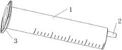
- a drug dissolver having an outer casing 1is provided with a conical head 2, the outer casing has a cavity, and the conical head is disposed on the outer casing, and is empty The cavity is in communication, and the rear end surface of the outer casing has a projection 3 which is closed in shape.
- the protrusioncontacts and adheres to the external object, so that the protrusion forms a sealed structure with the external object, and seals the inner space of the protrusion to prevent the outer surface of the outer surface and the outer object.
- the contact position between the air leaksis not limited to, but not limited to,
- the protrusionis a circular protrusion
- the protrusionis a square protrusion
- the protrusionis an elliptical protrusion
- the protrusionis a star-shaped protrusion
- the shape of the protrusionmay be any shape as long as the shape is sealed (so-called shape sealing means that the inner space of the protrusion is separated from the outer space by the protrusion, and is not connected)
- the sealing structurecan be formed with the external object to prevent the air leakage at the contact position between the outer casing and the external object, thereby achieving a relatively good sealing effect.
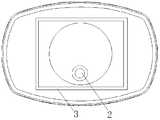
- the solvent disintegrator as described in Embodiment 1is different from the embodiment in that, as shown in FIG. 2A, the shape of the protrusion 3 of the solvent dissolver is the same as the cross section of the outer casing, such that the protrusion 3
- the inner wallis fitted and identical to the inner wall of the outer casing to prevent the inner wall of the outer casing from being uneven due to the projection 3, which hinders the movement of the rubber stopper placed therein.
- the cross section and the protrusion 3 of the outer casing of the solvatormay be circular or elliptical, or may be other shapes such as a star shape, a zigzag shape or the like (in a specific implementation, the selection or design may be performed according to actual needs. ), as long as the cross section of the outer sleeve and the shape of the projection 3 are the same.
- the cross section of the outer casing of the solvent and the projections 3are circular, which is convenient to manufacture and facilitates screwing of the dissolver.
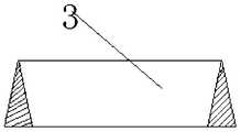
- the protrusion 3 and the external objectmay be in planar contact and sealed, such that when sealing, the top end of the protrusion 3 presses the contact plane of the external object to achieve a sealing effect;
- the setting of 3reduces the contact area between the rear end of the solvent-dissipating jacket and the external object, improves the pressure of the outer surface of the outer casing and the external object, thereby improving the sealing property; in addition, the setting of the projection 3 reduces the rotational dissolution
- the friction generated by the devicefacilitates the rotation of the solvent dissolver; thus, only the position where the protrusion 3 is in contact with the external object (the external article) is flat, and the edge of the external object is not in contact, so that the sealing can be achieved.
- the top end of the protrusion 3may be an acute angle, an ellipse or an obtuse angle, so that the sealing is more firm.
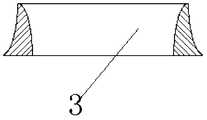
- the protrusion 3 and the external objectmay be in contact with and sealed by the edge, and the external object has a hole, and the protrusion 3 is inserted into the hole and is pressed and sealed with the inner edge of the hole; thus, the sealing effect better.
- the top end of the protrusion 3is arc-shaped outward from the center of the circle, so as to facilitate sealing sealing with the inner edge of the hole; as shown in FIG. 3B, the top end of the protrusion 3 can also be The inner circumference of the center of the arc is shaped to facilitate machining; the top end of the protrusion 3 may also have the shape shown in Fig. 3E as long as it can be pressed and sealed with the inner edge of the hole.
- a filteris arranged at the front end of the handle to blow a uniform, dispersed, and non-intersecting co-directional air source/clean airflow, and the air at the front end of the handle is replaced to achieve a local level of cleanliness to ensure replacement of the environment.
- the bacteria at the rear end of the dissolver rubber plugare blown by a uniform, dispersed, non-intersecting co-directional gas source/clean gas stream, and the bacteria therein are replaced.
- the current solvent dissolverthere are many bacteria hidden, and it is difficult to blow out (displace) the bacteria by simply blowing them in a uniform, dispersed, non-intersecting co-directional gas source/clean gas stream.
- a rubber stopperwherein a rear end surface of the rubber stopper 4 is a flat surface.
- the bacteriacannot be hidden on the rear end surface of the rubber plug, so that the bacteria can be blown out (displaced) by simply blowing, uniformly dispersing, and not intersecting the same direction air source/clean air flow.
- the rubber plug as described aboveis different from the embodiment in that, as shown in FIG. 4, the rubber plug 4 is a solid rubber plug, so that the production is convenient and the strength is sufficient, and the pneumatic driving is convenient;
- the rear end faceis flat, which facilitates the replacement of bacteria at the rear end face.
- the rubber plug according to the above embodimentis different from the embodiment in that, as shown in FIG. 5, the rubber plug 4 includes a rubber sleeve 41 and a core rod 42, and the front end of the core rod 42 is inserted into the rubber sleeve. 41, and the rear end of the core rod 42 has a rear end cover 421, the rear side of the rear end cover 421 is flat and the rear end cover abuts against the rubber sleeve 41.
- the rear end surfaceis a flat surface (the rear side of the rear end cover 421), which facilitates the replacement of the rear end surface bacteria.
- the rubber plugs in the embodiment 4 and the embodiment 5are two different forms of the rubber plug in the embodiment 3, and may also be other types of rubber plugs. As long as the rear end surface is flat, the bacteria cannot be hidden in the rubber. The rear end surface of the plug allows the bacteria to be blown out (displaced) by simply blowing in a uniform, dispersed, non-intersecting co-directional source/clean air stream.
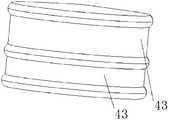
- the rubber plug as described aboveis different from the embodiment in that, as shown in FIG. 6A, the rubber plug 4 has an annular groove 43 at its side to facilitate the position of the rubber plug.
- the annular groove 43is disposed at the front end of the rubber plug 4; the annular groove 43 may also be disposed in the middle of the rubber plug 4 or the rear end of the rubber plug;
- the annular groove 43defines the position of the rubber plug, and also reduces the contact area between the rubber stopper and the solvent jacket, reduces the resistance of the rubber sheath to the surrounding outer casing, and increases the smoothness of the rubber plug.
- the number of the annular grooves 43is two, so that the rubber plug and the solution can be further reduced.
- the contact area of the drug coatincreases the smoothness.
- the present embodimentdiffers from the above embodiment in that the inner wall of the outer casing 1 of the solvent dissolver has a limit end for defining the position of the rubber plug 4.
- the limiting endis an annular inner protrusion 11 surrounding the inner wall of the outer casing 1 , and the annular inner protrusion 11 is inserted into the annular groove 43 to position the rubber plug 4 . limited.
- the width of the annular inner protrusion 11is the same as the width of the annular groove 43, so that when the position of the rubber plug needs to be defined, the annular inner protrusion 11 just snaps into the annular groove 43 and is limited. Bit rubber plug.
- the annular inner protrusion 11is disposed at the rear of the outer casing 1 so that the rubber stopper can be fixed to the rear end of the solvent dissolver, because the medicine can be dissolved when the dispenser is replaced during the aseptic dispensing.
- the bacteria in the deviceare replaced, and the back end of the rubber stopper of the solvent dissolver is flush with the rear end surface of the outer casing when the solvent dissolver is replaced, so that the uniform, dispersed, and non-intersecting co-directional gas source/clean air flow can be blown.
- the bacteriaare blown out (displaced).
- the rubber plug of the solvent dissolveris located in the middle of the outer casing, a columnar depression is formed in the rubber plug and the rear of the outer casing, and the uniform, dispersed, non-intersecting co-directional gas source/clean air flow is blown.
- turbulent flowis generated and cross-mixed at the depression, so that the bacteria in the depression cannot be blown away (replaced).
- the annular inner protrusion 11limits the rubber stopper to the rear end of the outer casing, and the rear end surface of the rubber plug is flush with the rear end surface of the outer casing protrusion 3, thus The rear end surface of the drug dissolver is flat to facilitate the replacement of bacteria on it.
- the rear end surface of the rubber plugcooperates with the inner side of the protrusion 3 to prevent the rubber plug from being disposed at the rear end of the solvent dissolver, the rear end of the rubber plug and the protrusion 3 There is a gap in the end that hides the bacteria and cannot be replaced.
- the present embodimentis different from the above, in that the solvent has a bead 12 which is disposed on the outer casing 1 and extends to the outside of the outer casing 1; It is convenient to fix the solvent dissolver.
- the bead 12is two and symmetrically disposed on the outer casing 1 so that the strength of the bead 12 and the outer casing 1 can be enhanced.
- the bead 12is disposed in the middle of the outer casing 1; in fact, the bead may also be disposed at the rear or the front of the outer casing 1 as long as the outer casing 1 can be fixed by the bead 12 can.
- the bead 12may be one or a plurality of symmetrically disposed on the outer casing 1; thus, the strength of the bead 12 and the outer casing 1 may be enhanced.
- the bead 12is flush with the rear end surface of the outer casing 1, which facilitates production, prevents the rear end portion of the outer casing 1 from being grooved, and cannot replace contaminants such as bacteria hidden therein.
- the handle 5is provided with an elastic member 61, and the elastic member 61 and the rear end of the outer sleeve are convex. 3 fits to form a sealed structure.
- the projectionis sealed with the inner space of the handle to prevent air leakage at the contact position between the outer sleeve and the handle.
- the elastic member 61has a hole through which the hole communicates with a cavity in the outer sleeve.
- the elastic member 61may be a circular shape, a square shape, an elliptical shape, or a star shape.
- the shape of the hole in the elastic member 61may also be a circular shape.
- the square shapemay be an ellipse or a star shape; the shape of the hole may be the same as the shape of the elastic member 61, or may be randomly combined; the elastic member 61 may correspond to the shape of the protrusion.
- the non-voidingmeans that the elastic member 61 and the protrusion 3 are in contact with each other and have no gap, so that the elasticity
- the sealing effectcan be achieved at the joint portion, and a better sealing effect can be achieved.
- the hole of the elastic member 61is circular, which facilitates the rotary seal of the solvent dissolver.
- the elastic member 61is an elastic ring (that is, the shape of the elastic member 61 and the holes of the elastic member 61 are all circular), which is convenient for processing.
- the solution and the handle as described aboveare different from the embodiment in that the protrusion 3 is in planar contact with the front end surface of the elastic member 61 and is sealed, so that the top end of the protrusion 3 is squeezed when sealed.
- the front end surface of the elastic member 61is pressed to achieve a sealing effect; thus, the protrusion 3 is disposed such that the rear end surface of the outer sleeve is not in direct contact with the front end surface of the elastic member 61, and the rear end of the solvent jacket and the elastic member are reduced.
- the contact area of the front end surface of the 61increases the pressure at which the outer surface of the outer sleeve and the elastic member 61 are pressed against each other, thereby improving the sealing property; in addition, the arrangement of the projections 3 reduces the friction generated when the solvent dissolver is rotated, and is convenient. The rotation of the dissolver is snapped; thus, only the position where the protrusion 3 is in contact with the external object is flat, and the seal can be achieved without contacting the edge of the external object.
- the front end surface of the protrusion 3 and the elastic member 61may also be contacted and sealed by the edge, the hole of the elastic member 61 is circular, and the protrusion 3 is inserted into the circular shape of the elastic member 61. Hole and the hole The inner edge of the hole is squeezed and sealed; thus, the deformation of the pressing portion is larger and the sealing effect is better.
- the handlefurther includes: a mounting groove 73, and the mounting groove 73 and the solvent dissolver
- the curling 12cooperates to fix and fix the dissolver on the handle 5.
- the solvent dissolvercan be directly mounted on the handle 5 through the mounting groove, which is simple and convenient, and is convenient for quick installation of the solvent dissolver.
- the nurse's dispensingneeds to be configured thousands of times a day, which requires convenient and quick installation and disassembly of the solvent dissolver, and the installation is firm.
- the mounting groove 73is a circular groove which is open near a side wall 74 of the front end, and the bead 12 is inserted into the circular groove through the opening, and is rotated and then snapped into the circular groove. In this way, the installation is simple, and the curling 12 can be taken out from the circular groove after being rotated to the initial position during disassembly, which is convenient and quick to disassemble, and is convenient for replacing the solvent dissolver.
- the openingextends from the edge of the side wall 74 of the circular groove to the center, and the extended end forms a circular recess 75 of the same diameter as the solvent outer casing 1 such that the bead 12 is inserted into the circle
- the outer sleeve of the solventdissolves into the circular recess 75, the axis of the outer sleeve coincides with the center of the circular recess 75, and then the outer sleeve 1 is rotated, and the curl 12 is inside the circular groove.
- the outer circumference of the outer casing 1is rotated and is transferred from the opening into the circular groove to catch the bead 12.
- the circular recess 75positions the outer casing of the solvent dissolver, facilitates screwing, and facilitates the insertion of the curling edge 12 (otherwise, the prevention of incorrectness may occur, resulting in the curling edge 12 not corresponding to the circular groove, and the buckle cannot be engaged. The problem).
- a blocking end(not shown) is disposed in the mounting groove 73 (circular groove) to limit the rotating bead 12 to prevent the rotation of the bead 12 from rotating, so that the card is not stable or rolled.
- the edge 12is unscrewed from the circular groove (after being rotated by 180 degrees, it will be unscrewed therefrom, and the larger rotation will make the portion of the bead 12 being too small, which is not stable enough).
- the front end portion 51 of the handle 5projects forward, which is convenient for holding.
- the inner side of the front end portion 51is an arcuate groove, which is the same as the outer wall of the outer casing 1, such that the inner side of the front end portion 51 cooperates with the outer wall of the outer casing 1 to facilitate the outer casing 1 to fit the front end portion 51; and thus, when the handle is held, A part is gripped on the outer side of the front end portion 51, and a part is gripped on the outer side of the outer casing 1, and the outer casing 1 is pressed toward the inner side of the front end portion 51 to fix the solvent dissolver.
- the mounting groove 73is disposed at a rear side of the front end portion 51, and a crimping groove 76 is disposed at an inner side of the front end portion 51 near the mounting groove 73, and the side of the crimping groove 7, 6 and the mounting groove
- the side wall 74 of the abutment 73abuts, and the beading groove 76 is flush with the circular recess 75, so that the bead 12 can be placed in the bead groove 76 to be pushed backwards, after passing through the circular notch 75. Push the crimp into the circular groove; facilitate the push and facilitate the solvent dissolver The bacteria at the back end are replaced.
- the handlefurther includes:
- a filter 62that filters the gas flowing through it and filters it into a clean gas, the filter 62 being in communication with the air passage of the main unit through the quick cone head 63.
- the airflow blown into the solventcan be filtered and connected through the quick cone head 63, which can be quickly inserted and removed for easy replacement of the filter.
- the air outlet of the filter 62is provided with a plurality of equal-diameter small holes, so that the air outlets of the filter are smooth airflows that are all and do not intersect, so as to facilitate the purification of the front end.
- the filter 62includes an air outlet case 621, an air intake case 622, and a filter film 623.
- the air outlet caseis fixedly coupled to the air intake case, and the filter film 623 is disposed in a cavity between the air outlet case and the air intake case.
- the air inlet shell 622has a tapered shape, and the inner wall is evenly provided with reinforcing ribs for increasing the strength of the air inlet shell 622, and cooperates with the air outlet shell 621 to clamp the filter membrane 623, and the clean air enters the small inlet of the tapered air inlet shell 622. .
- the air outlet shell 621is a circular buckle cover structure matched with the large opening of the air inlet shell 622, and is fastened to the air inlet shell 622.
- the air outlet shell 621is provided with a certain number of small diameter holes as an air outlet, which can make the air flow area It is enlarged, and the outlets are evenly distributed, which can provide a large area of clean gas which is relatively slow, uniform, non-intersecting, and free of turbulence and turbulence.
- the diameter of the filter outlet shellis 2.5 cm, which can produce a gas bundle with a diameter of 2.5 cm.
- the front end of the air outletis replaced with a clean environment to achieve a local aseptic effect;
- the surface of the air outlet shell 621is a flat surface, that is, the air outlet shell 621 is removed from the outer surface of the air outlet hole, and there is no protrusion or groove.
- the venting shell 621is provided with reinforcing ribs on the side of the air inlet shell 622 for improving the strength of the air outlet shell 621 and cooperating with the air inlet shell 622.
- the filter membrane 623is clamped.
- the arrangement of the reinforcing ribs on the filterincreases the overall strength, and also clamps the intermediate filter film 623 to prevent the film from being broken and improves the filtration efficiency.
- the number of ribs of the air outlet casing 621is two, and one or more ribs may be provided.
- the number of ribs of the air inlet casing 622is six, and of course, less or more than six may be provided, and different numbers of reinforcements may be flexibly set. Reinforcement to meet different requirements under different designs.
- the ribs on the air outlet casing 621 and the air inlet casing 622are both in a shape, and of course, other shapes with a curvature or an angle may be used, that is, the shape of the ribs may also be specifically set according to actual needs. set.
- the filter membrane 623is disposed between the gas outlet shell 621 and the gas inlet shell 622.
- the filter membrane 623 of the present inventionadopts a 0.24 mm pore size polytetrafluoroethylene filter membrane, which is generally used and low in cost, and has a pore size. It is the threshold of sterile filtration, which can play a good role in filtering gas.
- the air inlet shell 622serves as an air inlet
- the air outlet shell 621serves as an air outlet.
- the gasenters from the small opening of the air inlet shell 622, and is filtered by the filter film 623 to become a clean gas.
- the gas beam blown from the gas outlet shell 621can be up to 2.5 cm in diameter, the gas output area is increased, and the air flow is slow, uniform, and does not cross each other, and there is no turbulent flow and no turbulence, and the front end of the gas outlet shell 621 can be The area is replaced by a clean and sterile environment to achieve a local level of cleanliness.
- the filter structure of the inventionis simple and reasonable, and the air outlet shell 621 adopts a circular buckle cover with small holes, which reduces the resistance of the gas flowing through the filter, and can provide uniform, slow, non-crossing, large-area cleanliness.
- the airreaches the local clean and sterile effect at the front end of the filter, and has high filtration efficiency and good effect.
- the handle 5further includes a fixing member 64 and a catching member 65.
- the elastic member 61is attached to the air outlet casing 621 of the filter.
- the shape of the locking member 65is adapted to the filter 8.
- the filteris disposed in the engaging member 65, and the fixing member 64 is directly buckled on the engaging member 65.
- the quick cone head 63is a double-headed fast cone head. One end of the double-headed fast cone head is connected to the filter through the connecting clip 65, and the other end is connected to the closed air tube, so that the plug is easy to insert and remove, and the sealing property is good.
- the handle of the embodimentis connected by a gas pipe and a power line and a gas source output device, and before the solvent dissolver is installed to the handle, the gas source output device supplies a small power source to the handle, and the small power source enters the intake shell 622 through the air pipe.
- a clean and sterile gasis obtained, and the filtered gas passes through the gas outlet shell 621 and is blown out from the gas outlet hole of the gas outlet shell 621 to obtain a clean air which provides uniform, slow, non-crossing and large area, and can be
- the area at the front end of the air outlet casing 621is replaced with a clean and sterile environment to achieve a local level of cleanliness; when the solvent dissolver is mounted to the handle, the front end of the handle is blown for a small power source, and the front end region of the handle is replaced with a clean sterile Environment, the applicator is attached to the inside of the front end of the handle, and the hand-held squeezer is pressed against the handle and pushed in the direction of the filter.
- the handlealso includes an O-ring 66 disposed between the filter and the resilient member 61 for preventing hard grinding and for cushioning.
- the elastic member 61is buckled on the air outlet casing 621 of the filter, and an O-ring 7 is disposed between the elastic member 61 and the filter.
- the intermediate diameter of the O-ring 7is consistent with the solvent dissolver and is set to 2 cm. It is used to prevent hard grinding and to act as a buffer, thereby increasing the service life of the elastic member 61.
- the rear end of the fixing member 64is engaged with the front end of the engaging member 65, so that the elastic member 61, the O-ring 66 and the filter 62 are snap-fitted together to form a whole body, which is convenient for overall replacement.
- the outer casing of the handleis connected by a snap, which facilitates opening the outer casing and replacing the filter therein.
- the mounting groove 73is disposed on the fixing member 64.
- the embodimentis a solvent dissolver position determining device comprising a drug dissolver and a handle, wherein the drug dissolver has an identification portion thereon, and the handle has In a measuring unit, the measuring unit generates a change signal after the marking portion approaches, and measures the position of the solvent dissolver.
- the indicator portionis just near the measurement portion, and the measurement portion generates a signal change, and the subsequent host confirms that the solvent dissolver reaches the designated position by the signal change, thereby controlling the gas flow rate.
- the bacteria and other contaminants at the front end of the handlecan be gradually taken out to form a sterile environment at the front end of the handle.
- the airflowis installed.
- the solvent dissolverthe solvent dissolver is gradually approached to the front end of the handle, and when the rear end of the solvent dissolver enters the aseptic environment at the front end of the handle, the clean, non-intersecting airflow is blown to the rear end of the dissolver, thereby continuously blowing
- the bacteria at the back end of the solvent dissolverare replaced (in order to achieve a better replacement effect, the back end of the dissolver can stay for a while after approaching the handle).
- the flow rate of the replacement bacterianeeds to be slow to prevent the turbulent flow such as eddy currents from coming into contact with the inner wall of the handle hole (the turbulent flow will cause the internal flow to cross, so that the purification of the surrounding environment is poor), and the glue to the dissolver
- the turbulent flowsuch as eddy currents from coming into contact with the inner wall of the handle hole (the turbulent flow will cause the internal flow to cross, so that the purification of the surrounding environment is poor)
- the glue to the dissolverWhen the plug is driven, it is necessary to change the pressure at the back end of the rubber plug in a short time, which requires a rapid air flow, and the two air flows need to be switched when the solvent dissolver is mounted on the handle, which requires Whether the solvent dissolver is in place for testing.
- the installation of the drug dissolverneeds to be fast, but the quick installation means that the installation is easy to make mistakes. If it is wrong, it is easy to damage the outside or the handle. At this time, the position detecting device will only produce a signal change after the solvent dissolver is installed. The slow clean airflow is replaced by a high-speed clean airflow to prevent damage to the high-speed airflow when the dissolver is not in place.
- the solvent position measuring device as described aboveis different from the embodiment in that, as shown in FIG. It is shown that the solvent dissolver has a light shielding strip 13 on the handle and a photoelectric sensor 71.
- the photoelectric sensorcooperates with the light shielding tape to measure the position of the solvent dissolver.
- the light shielding tapeis close to the photoelectric sensor, and after being mounted in position, the light shielding tape covers the light between the photoelectric sensors (in order to express the light shielding tape, the solvent dissolver is rotated by 180 degrees), The light between the photosensors is broken, so that the photoelectric sensor signal changes, causing the airflow speed to change.
- the light shielding tapeleaves the photoelectric sensor to restore the signal, so that the airflow speed is restored; thus, whether the solvent dissolver is installed or removed can be detected, and the airflow can be controlled;
- the light shieldwill leave the position of the photoelectric sensor, causing the photoelectric sensor signal to change, which can prompt the user to dissolve the drug and prevent the drug from continuing to be dispensed after the solvent is tilted. So that the external bacteria enter the back end of the solvent dissolver.
- the solvent dissolveris used for dispensing, the cone head 2 is disposed at the front end of the outer sleeve, and the cone head is located at the edge of the front end surface of the outer sleeve, not from the central position (this is due to the state's prescription for the medicinal dissolver)
- the light shielding strip 13is disposed on the outer wall of the outer casing 1 opposite to the projection of the cone on the cross section of the outer casing (ie, their projections are on both sides of the center of the outer casing) so that when combined with the handle
- the light shielding tapeis adjacent to a side where the handle protrudes, and cooperates with the photoelectric sensor 71, and the cone head is away from a side where the handle protrudes, which is convenient for dispensing medicine.
- the scale of the solventis placed on the side of the outer casing adjacent to the light shielding strip 13 so that it can be read.
- the scale of the medicinalnatoris disposed in the middle of the cover belt 13 and the cone, so that the scale can be clearly read from the side when dispensing. (Setting on one side of the light-shielding belt 13, the side on which the handle protrudes during installation will block the scale by half, which is inconvenient to read).
- the present embodimentis different from the above embodiment in that the marking portion of the solvent dissolver is the curling edge 12, and the front end surface of the handle is provided with a triggering end 72, the triggering end corresponding to the position of the curling edge 12 of the solvent dissolver, such that when the solvent dissolver is installed, the curling edge is close to the handle and abuts against the triggering end, and the triggering end is pressed to generate an in-position signal , the position of the dissolver is measured.
- the trigger endcan be a micro switch, which is convenient for triggering.
- the present embodimentis different from the above-mentioned embodiment in that the marking portion of the solvent dissolver is the curling edge 12, and the front end surface of the handle is provided with a trigger end 72.
- the trigger endcorresponds to a position at which the curl 12 of the solvent dissolveer is rotated by 90 degrees, so that when the solvent dissolver is installed, the curl is close to the handle, and the curl After turning 90 degrees, it is pressed against the trigger end. After the trigger end is pressed, an in-position signal is sent to measure the position of the dissolver.
- the settingis convenient and easy to trigger; and the signal change can be made when the solvent dissolver is installed in place or disassembled or tilted, so that the user can clearly understand the state of the dissolver.
- the trigger endcan be a micro switch, which is convenient for triggering.
- the present embodimentis different from the above-described embodiment in that the solvent dissolver is provided with a magnet 14 at a corresponding position of the handle, and the magnet and the The magnet sensor is coupled to measure the position of the solvent dissolver.
- the magnetmoves toward the magnet sensor, and after being mounted in position, the magnet contacts (or approaches) the magnet sensor, causing the magnet sensor signal to change, causing the airflow speed to change.
- the magnetis moved away from the magnet sensor to restore the signal, so that the airflow speed is restored; thus, whether the solvent dissolver is installed or removed can be detected, and the airflow can be controlled; During the dispensing process, if the solvent dissolver or falls out, the magnet will move away from the magnet sensor, causing the signal of the magnet sensor to change, which can prompt the user of the state of the drug dissolver and prevent the drug from continuing to be dispensed after the solvent is tilted. So that the external bacteria enter the back end of the solvent dissolver.
- the range of the magnet sensor induction magnetcan be set according to the actual situation.
- this embodimentis an aseptic dispensing system comprising:
- the handle 5 described abovehas a rear end connected to the main body 9 through a pipe (not shown), and controls the air source output of the main engine.
- the hostair source output device
- the hostoutputs a small flow rate of airflow to the handle through the pipeline, and the airflow is filtered through the filter in the handle, and the clean, non-intersecting clean airflow is blown out from the front end of the handle,
- the front end of the handleis cleaned and replaced with a sterile environment;
- the solvent dissolveris installed, the rear end of the dissolver is placed close to the handle and enters a sterile environment, so that the clean air is blown at the back end of the dissolver and pauses for a period of time to dissolve
- the rear end of the medicine deviceis replaced by aseptic; then the solvent dissolver is mounted on the handle, and the marking portion on the handle is triggered to change the signal of the marking portion, and the change controls the delivery of the small airflow by the host; when dispensing, press the handle On the upper advance button, the control host outputs a large airflow outward, pushes the rubber plug in the dissolver forward, and extrudes
- the present embodimentis different from the present embodiment in that it is a schematic structural view of the drug dissolver of the embodiment 18 of the present invention.
- 19is a schematic view showing the state of use of a drug dissolver for a dispensing system according to Embodiment 18 of the present invention.
- the drug dissolver for the dispensing system provided by the embodimentcomprises a jacket 1 having a bead 813 at one end and a cone 12 at the other end.
- the bead 813 and the cleaning device 84are threaded or snap-fitted or claw-hooked or screw-fastened or magnetically coupled.
- the cone 12 and the needle 82are threaded or snap-fitted or hooked or screwed or magnetically connected.
- the rubber stopper 4is built in the outer casing 1.
- the rubber plug 4moves axially within the outer casing 1.
- the rubber stopper 4divides the outer casing 1 into a first cavity 811 and a second cavity 812.
- the material used to make the rubber plug 4is a
- the purifying device 84is in communication with the gas output unit 89 via a joint 85.
- the purifying device 84is further provided with a gas line 86.
- One end of the gas line 86communicates with the joint 85, and the other end communicates with the second chamber 812.
- the gas line 86is provided.
- a sealing ring 88is provided at the junction of the purifying device 84 and the bead 813.
- the cross-sectional area of the end of the gas line 86 communicating with the outer casing 1is smaller than the cross-sectional area of the rubber plug 4, which has the advantage of preventing the rubber stopper 4 from coming out of the outer casing 1 and entering the gas line 86.
- the outer casing 1is hermetically connected to the purifying device 84.
- the gas output unit 89presses air into the gas line 86. Since the gas line 86 communicates with the second chamber 812, the air pressure in the second chamber 812 rises. When the air pressure in the second cavity 812 is higher than the first cavity 811, the high pressure gas in the second cavity 812 pushes the rubber stopper to move toward the needle 82. The air in the first cavity 811 is completely discharged. When the air in the first cavity 811 is completely discharged, the needle 82 is inserted into the liquid medicine bottle, and then the gas in the second cavity 812 is sucked out through the gas output unit 89.
- the rubber plug 4moves toward the cleaning device 84 to suck the liquid into the first cavity 811. Then, the liquid medicine bottle is removed, and the needle 82 is inserted into the lyophilized powder medicine bottle, and the control gas output unit 89 presses air into the gas line 86.
- the air pressure in the second chamber 812is higher than the first chamber 811
- the high pressure gas in the second cavity 812pushes the rubber stopper to move toward the needle 82
- the chemical liquid in the first cavity 811flows into the lyophilized powder medicine bottle, and after the liquid medicine and the lyophilized powder are thoroughly mixed,
- the gas in the second cavity 812is sucked out by the gas output unit 89.
- the rubber plug 4moves toward the cleaning device 84, and further, The mixture of the lyophilized powder and the drug solution is drawn into the first cavity 811 to complete the fusion.
- the air filter 86is provided with the air filter 87, the air flowing into the second cavity 812 is purified as sterile air, preventing the inside of the outer casing 1 from being contaminated, and the melting process is further improved. Safety.
Landscapes
- Health & Medical Sciences (AREA)
- Vascular Medicine (AREA)
- Engineering & Computer Science (AREA)
- Anesthesiology (AREA)
- Biomedical Technology (AREA)
- Heart & Thoracic Surgery (AREA)
- Hematology (AREA)
- Life Sciences & Earth Sciences (AREA)
- Animal Behavior & Ethology (AREA)
- General Health & Medical Sciences (AREA)
- Public Health (AREA)
- Veterinary Medicine (AREA)
- Medical Preparation Storing Or Oral Administration Devices (AREA)
Abstract
Description
Translated fromChinese本发明涉及医疗器械技术领域,具体涉及一种溶药器及溶药器位置测定装置和无菌配药系统。The invention relates to the technical field of medical instruments, in particular to a drug dissolver and a drug dissolver position measuring device and an aseptic dispensing system.
市面上大多数的溶药器都是通过手动推拉芯杆带动溶药器内部的活塞,以实现其融药功能。上述的溶药器虽然有着操作方便,且便于携带等优点,但是该溶药器采用人工操作,融药效率低下。Most of the solvent dissolvers on the market use a manual push-pull core to drive the piston inside the dissolver to achieve its melt function. Although the above-mentioned solvent dissolver has the advantages of convenient operation and being easy to carry, the solvent dissolver is manually operated, and the melt efficiency is low.
鉴于上述缺陷,本发明创作者经过长时间的研究和实践终于获得了本发明。In view of the above drawbacks, the creators of the present invention have finally obtained the present invention after a long period of research and practice.
发明内容Summary of the invention
为解决上述技术缺陷,本发明采用的技术方案在于,提供一种溶药器,其包括外套,用于提供容纳药剂的空腔,所述外套一端设有卷边,所述外套另一端设有锥头。In order to solve the above technical defects, the technical solution adopted by the present invention is to provide a solvent dissolver comprising a jacket for providing a cavity for accommodating a medicament, the jacket having a bead at one end and the other end of the jacket being provided Cone head.
较佳的,所述外套,用于提供容纳药剂的空腔,所述外套一端设有卷边,用于将所述外套与净化装置可拆卸密闭连接,所述外套另一端设有锥头,用于将所述外套与针头可拆卸连接。Preferably, the outer casing is configured to provide a cavity for containing a medicament, and the outer casing is provided with a bead at one end for detachably and sealingly connecting the outer casing with a purifying device, and the other end of the outer casing is provided with a cone. For detachably connecting the outer sleeve to the needle.
较佳的,所述卷边与所述净化装置之间采用螺纹连接或卡扣连接或爪钩连接或旋扣连接或磁力连接。Preferably, the bead and the cleaning device are connected by a screw connection or a snap connection or a claw hook connection or a screw connection or a magnetic connection.
较佳的,所述卷边与所述净化装置连接处设置一密封圈。Preferably, a sealing ring is disposed at the junction of the bead and the cleaning device.
较佳的,所述第二连接件与所述针头之间采用螺纹连接或卡扣连接或爪钩连接或旋扣连接或磁力连接。Preferably, the second connecting member and the needle are connected by a screw connection or a snap connection or a claw hook connection or a screw connection or a magnetic connection.
较佳的,所述外套内部设置有胶塞,所述胶塞在所述外套内轴向运动。Preferably, the inside of the jacket is provided with a rubber plug, and the rubber plug moves axially within the jacket.
较佳的,所述外套外形为圆柱体或椭圆柱体或长方体或三棱柱体。Preferably, the outer shape of the outer casing is a cylinder or an elliptical cylinder or a rectangular parallelepiped or a triangular prism.
较佳的,所述外套的后端面上具有凸起,所述凸起形状封闭。Preferably, the outer surface of the outer sleeve has a protrusion, and the convex shape is closed.
较佳的,所述溶药器的凸起的形状与所述外套的横截面相同,以使所述凸起的内壁与所述外套的内壁贴合且相同。Preferably, the shape of the protrusion of the solvent is the same as the cross section of the outer casing such that the inner wall of the protrusion fits and is identical to the inner wall of the outer casing.
较佳的,所述溶药器具有卷边,所述卷边设置在所述外套上且向所述外套外侧延伸。Preferably, the solvent has a bead disposed on the outer sleeve and extending outwardly of the outer sleeve.
提供一种与所述的溶药器配合的手柄,其所述手柄上设置有弹性件,所述弹性件与所述外套后端的凸起配合,形成密封结构。Providing a handle mated with the solvent, wherein the handle is provided with an elastic member, the elasticityThe piece cooperates with a projection at the rear end of the outer sleeve to form a sealing structure.
较佳的,所述弹性件上具有孔洞,所述孔洞通过所述凸起与所述外套内的空腔连通。Preferably, the elastic member has a hole through which the hole communicates with a cavity in the outer sleeve.
较佳的,所述凸起与弹性件的前端面内边沿接触并密封。Preferably, the protrusion contacts and seals the inner edge of the front end face of the elastic member.
较佳的,还包括胶塞,所述胶塞的后端面为平面。Preferably, the rubber plug is further included, and the rear end surface of the rubber plug is a flat surface.
较佳的,所述胶塞为实心胶塞。Preferably, the rubber plug is a solid rubber plug.
较佳的,所述胶塞包括胶塞套和芯杆,所述芯杆前端插入所述胶塞套;所述芯杆后端具有后端盖,所述后端盖后侧为平面且所述后端盖紧贴所述胶塞套。Preferably, the rubber plug comprises a rubber plug sleeve and a core rod, the front end of the core rod is inserted into the rubber plug sleeve; the rear end of the core rod has a rear end cover, and the rear side of the rear end cover is flat and The back end cover is in close contact with the rubber sleeve.
较佳的,所述胶塞侧边具有环形槽,以对所述胶塞的位置进行限定。Preferably, the rubber plug has an annular groove on the side to define the position of the rubber plug.
较佳的,所述溶药器的外套的内壁上,具有限位端,对所述胶塞的位置进行限定。Preferably, the inner wall of the outer casing of the solvent has a limiting end, and the position of the rubber plug is defined.
较佳的,所述限位端为环绕在所述外套内壁上的环形内凸起,所述环形内凸起卡入所述环形槽内,对所述胶塞的位置进行限定。Preferably, the limiting end is an annular inner protrusion surrounding the inner wall of the outer sleeve, and the annular inner protrusion is inserted into the annular groove to define a position of the rubber plug.
较佳的,所述环形内凸起设置在所述外套后部,将所述胶塞限位在所述外套后端。Preferably, the annular inner protrusion is disposed at the rear of the outer sleeve to limit the rubber plug to the rear end of the outer sleeve.
一种溶药器位置测定装置,其包括上述所述的溶药器和手柄,其中,所述溶药器上具有一标识部,所述手柄上具有一测定部,所述测定部在所述标识部靠近后产生变化信号,对所述溶药器位置进行测定。A drug dissolver position determining device comprising the above-mentioned drug dissolver and handle, wherein the drug dissolver has an identification portion, the handle has a measuring portion, and the measuring portion is A change signal is generated after the identification portion is approached, and the position of the solvent dissolver is measured.
较佳的,所述溶药器上具有一遮光带,手柄上具有一光电传感器,所述光电传感器与所述遮光带配合,对所述溶药器的位置进行测定。Preferably, the solvent dissolver has a light shielding tape, and the handle has a photoelectric sensor, and the photoelectric sensor cooperates with the light shielding tape to measure the position of the solvent dissolver.
较佳的,所述溶药器具有锥头,所述锥头设置在所述溶药器外套的前端,且所述锥头位于所述外套前端面的边缘位置。Preferably, the solvent has a cone, the cone is disposed at a front end of the solvent jacket, and the cone is located at an edge of the front end face of the jacket.
较佳的,所述遮光带设置在所述外套的外壁上,与所述锥头在所述外套的横截面上的投影相对。Preferably, the light shielding tape is disposed on an outer wall of the outer casing opposite to a projection of the cone on a cross section of the outer casing.
较佳的,所述溶药器的刻度设置在外套上靠近所述遮光带的一侧。Preferably, the scale of the solvent is disposed on a side of the outer casing adjacent to the light shielding tape.
较佳的,所述溶药器的标识部为所述卷边,所述手柄的前端面设置有触发端,所述触发端与所述溶药器的卷边位置对应。Preferably, the marking portion of the solvent dissolver is the curling edge, and the front end surface of the handle is provided with a trigger end, and the trigger end corresponds to a curling position of the solvent dissolver.
较佳的,所述溶药器的标识部为所述卷边,所述手柄的前端面设置有触发端,所述触发端与所述溶药器的卷边旋转90度的位置对应。Preferably, the marking portion of the solvent dissolver is the curling edge, and the front end surface of the handle is provided with a trigger end corresponding to a position at which the curl of the solvent dissolves by 90 degrees.
较佳的,所述触发端可以为微动开关。Preferably, the trigger end can be a micro switch.
较佳的,所述溶药器上设置有磁铁,所述手柄的对应位置处设置有磁铁感应器,所述磁铁与所述磁铁感应器配合,对所述溶药器的位置进行测定。Preferably, the solvent is provided with a magnet, and a magnet sensor is disposed at a corresponding position of the handle.The magnet cooperates with the magnet inductor to measure the position of the solvent dissolver.
一种具有所述溶药器位置测定装置的无菌配药系统,其还包括:An aseptic dispensing system having the solvent position determining device, further comprising:
主机,其用以提供气源动力输出;a host for providing a power source power output;
所述手柄后端与所述主机通过管道连通,并对所述主机的气源输出进行控制。The back end of the handle is in communication with the host through a pipe and controls the air source output of the host.
较佳的,所述溶药器上具有一标识部,所述手柄上具有一测定部,所述测定部在所述标识部靠近后产生变化信号,对所述溶药器位置进行测定。Preferably, the solvent applicator has a marking portion, and the handle has a measuring portion, and the measuring portion generates a change signal after the marking portion approaches, and measures the position of the solvent dissolver.
与现有技术比较本实用新型的有益效果在于:可以通过卷边与外置设备组合,便于配药;溶药器内壁始终处在洁净的空气中,避免了带有细菌的空气或使用者对溶药器内部产生的接触性污染;利用气体压力作为动力,提高了融药的效率,便于使用者进行操作;制造成本低,适宜推广生产。Compared with the prior art, the utility model has the beneficial effects that the medicine can be easily combined by the combination of the crimping and the external equipment; the inner wall of the solvent dissolver is always in the clean air, and the air with the bacteria or the user is dissolved. Contact pollution generated inside the drug device; using gas pressure as power to improve the efficiency of the fusion drug, easy for the user to operate; low manufacturing cost, suitable for promotion of production.
为了更清楚地说明本发明各实施例中的技术方案,下面将对实施例描述中所需要使用的附图作简单地介绍。In order to more clearly illustrate the technical solutions in the various embodiments of the present invention, the drawings used in the description of the embodiments will be briefly described below.
图1是本实用新型溶药器的结构图;Figure 1 is a structural view of the drug dissolver of the present invention;
图2A是本实用新型溶药器的后视图一;Figure 2A is a rear view of the drug dissolver of the present invention;
图2B是本实用新型溶药器的后视图二;Figure 2B is a rear view two of the drug dissolver of the present invention;
图2C是本实用新型溶药器的后视图三;Figure 2C is a rear view of the drug dissolver of the present invention;
图2D是本实用新型溶药器的后视图四;Figure 2D is a rear view of the drug dissolver of the present invention;
图3A是本实用新型凸起的横截面图一;Figure 3A is a
图3B是本实用新型凸起的横截面图二;Figure 3B is a
图3C是本实用新型凸起的横截面图三;Figure 3C is a cross-sectional view of the protrusion of the present invention;
图3D是本实用新型凸起的横截面图四;Figure 3D is a cross-sectional view of the protrusion of the present invention;
图3E是本实用新型凸起的横截面图五;Figure 3E is a
图4是本实用新型胶塞一的结构图;Figure 4 is a structural view of the
图5是本实用新型胶塞二的结构图;Figure 5 is a structural view of the
图6A是本实用新型胶塞的结构图一;Figure 6A is a
图6B是本实用新型胶塞的结构图二;Figure 6B is a
图6C是本实用新型胶塞的结构图三;Figure 6C is a structural diagram 3 of the rubber plug of the present invention;
图7是本实用新型实施例7的结构图;Figure 7 is a structural view of Embodiment 7 of the present invention;
图8是本实用新型实施例7的示意图;Figure 8 is a schematic view of Embodiment 7 of the present invention;
图9是本实用新型卷边位置的示意图;Figure 9 is a schematic view of the crimping position of the present invention;
图10是本实用新型弹性件位置的示意图;Figure 10 is a schematic view showing the position of the elastic member of the present invention;
图11是本实用新型弹性件可能形状的示意图;Figure 11 is a schematic view showing the possible shape of the elastic member of the present invention;
图12是本实用新型手柄的结构图;Figure 12 is a structural view of the handle of the present invention;
图13是本实用新型手柄的爆炸图;Figure 13 is an exploded view of the handle of the present invention;
图14是本实用新型过滤器的结构图;Figure 14 is a structural view of the filter of the present invention;
图15是本实用新型溶药器位置测定装置的结构图一;Figure 15 is a structural diagram 1 of the apparatus for measuring the position of the drug dissolver of the present invention;
图16是本实用新型溶药器位置测定装置的结构图二;Figure 16 is a
图17是本实用新型无菌配药系统的结构图;Figure 17 is a structural view of the aseptic dispensing system of the present invention;
图18是本实用新型实施例18的溶药器的结构示意图;Figure 18 is a schematic structural view of a solvent dissolver according to Embodiment 18 of the present invention;
图18是本实用新型实施例18的溶药器的使用状态示意图。Figure 18 is a schematic view showing the state of use of the drug dissolver of Example 18 of the present invention.
以下结合附图,对本发明上述的和另外的技术特征和优点作更详细的说明。The above and other technical features and advantages of the present invention are described in more detail below with reference to the accompanying drawings.
一种溶药器,其包括外套,用于提供容纳药剂的空腔,所述外套一端设有卷边,所述外套另一端设有锥头。这样,可以通过卷边与外置设备组合,便于配药。A drug dissolver comprising an outer casing for providing a cavity for containing a medicament, the outer casing having a bead at one end and a tapered head at the other end of the outer casing. In this way, it can be combined with an external device by crimping to facilitate dispensing.
实施例1Example 1
在配药的时候,配药人员(如护士等)每天需要配置多大上千份的药物,每份药物都需要更换新的溶药器,因此溶药器与手柄需要能够快速插拔,且密封结合。At the time of dispensing, the dispensing personnel (such as nurses) need to configure thousands of drugs per day, and each drug needs to be replaced with a new drug dissolver. Therefore, the drug dissolver and the handle need to be able to be quickly inserted and removed, and sealed.
溶药器在配药的时候,需要通过后续的手柄进行气动驱动,驱动时的气动压强比较大,溶药器与手柄的结合端一般都具有缝隙(互相之间没有密封),驱动时的高压强会使得溶药器内的气体高速从缝隙冲出,容易造成损伤或者无法驱(溶药器)。When dissolving the drug, the solvent needs to be pneumatically driven by the subsequent handle. The pneumatic pressure during driving is relatively large, and the combined end of the solvent dissolver and the handle generally have a gap (no seal between each other), and the high pressure during driving is strong. It will cause the gas in the solvent dissolver to rush out from the gap at high speed, which may cause damage or drive (solvent).
如图1所示,一种溶药器,其具有外套1、所述外套上设有锥头2,所述外套具有空腔,所述锥头设置在所述外套上,且与所述空腔连通,所述外套的后端面上具有凸起3,所述凸起形状封闭。As shown in FIG. 1, a drug dissolver having an
这样,所述外套与外部物体连通时,所述凸起与外部物体接触并紧贴,使得所述凸起与外部物体成密封结构,对凸起的内部空间进行密封,防止外套与外部物体之间的接触位置漏气。In this way, when the outer sleeve is in communication with an external object, the protrusion contacts and adheres to the external object, so that the protrusion forms a sealed structure with the external object, and seals the inner space of the protrusion to prevent the outer surface of the outer surface and the outer object. The contact position between the air leaks.
如图2A所示,该凸起为圆形凸起;As shown in FIG. 2A, the protrusion is a circular protrusion;
如图2B所示,该凸起为方形凸起;As shown in FIG. 2B, the protrusion is a square protrusion;
如图2C所示,该凸起为椭圆形凸起;As shown in FIG. 2C, the protrusion is an elliptical protrusion;
如图2D所示,该凸起为星型凸起;As shown in FIG. 2D, the protrusion is a star-shaped protrusion;
由图2-图5中可以看出,该凸起的形状可以为任何形状,只要其形状密封(所谓形状密封,是指该凸起的内部空间与外部空间被该凸起隔断,没有相连),就可以与外部物体构成密封结构,防止外套与外部物体之间的接触位置漏气,从而达到比较好的密闭效果。As can be seen from FIG. 2 to FIG. 5, the shape of the protrusion may be any shape as long as the shape is sealed (so-called shape sealing means that the inner space of the protrusion is separated from the outer space by the protrusion, and is not connected) The sealing structure can be formed with the external object to prevent the air leakage at the contact position between the outer casing and the external object, thereby achieving a relatively good sealing effect.
实施例2Example 2
如实施例1所述的溶药器,本实施例与其不同之处在于,如图2A所示,所述溶药器的凸起3的形状与所述外套的横截面相同,这样凸起3的内壁与外套的内壁贴合且相同,防止因凸起3产生外套的内壁不平,对放入其中的胶塞的运动产生阻碍。The solvent disintegrator as described in
所述溶药器的外套的横截面和凸起3可以是圆形的,也可以是椭圆形的,也可以是星型、锯齿形等其他形状(具体实施时可以根据实际需要进行选择或设计),只要外套的横截面和凸起3的形状相同即可。The cross section and the
优选地,所述溶药器的外套的横截面和凸起3为圆形,这样,生产方便,且便于旋拧溶药器。Preferably, the cross section of the outer casing of the solvent and the
本实施例中,所述凸起3与外部物体可以为平面接触并密封,这样在密封时,所述凸起3的顶端挤压外部物体的接触平面,以达到密封效果;这样,所述凸起3的设置减少了溶药器外套的后端与外部物体的接触面积,提高了外套与外部物体相互挤压的压力,从而提高了密封性;另外,凸起3的设置减少了旋转溶药器时产生的摩擦力,便于溶药器的旋转卡接;这样,只需要凸起3与外部物体接触的位置(外部物品)为平整的,与外部物体的边沿不接触,就可以实现密封。其中,如图3A、图3B、图3C所示,凸起3的顶端可以为锐角、椭圆、钝角形,这样密封更加牢固。In this embodiment, the
本实施例中,所述凸起3与外部物体可以为边沿接触并密封,外部物体具有孔洞,所述凸起3插入所述孔洞并与所述孔洞的内边沿挤压密封;这样,密封效果更好。其中,如图3D所示,所述凸起3的顶端为圆心向外的圆弧状,这样便于与孔洞的内边沿挤压密封;如图3B所示,所述凸起3的顶端也可以为圆心向内的圆弧状,这样便于加工;所述凸起3的顶端也可以为图3E中所示的形状,只要其可以与孔洞的内边沿挤压密封即可。In this embodiment, the
实施例3Example 3
为了完成无菌配药,不仅需要在配药的过程中保持溶药器外套空腔内的无菌环境,在更换溶药器时也需要使得能够将溶药器内的细菌置换掉。本发明中主要通过在手柄的前端设置过滤器,从中吹出均匀、分散、不交叉的同向气源/洁净气流,对手柄前端空气进行置换,以达到局部百级的洁净度,以保证更换环境的无菌。同时,对于溶药器胶塞后端的细菌,通过均匀、分散、不交叉的同向气源/洁净气流进行吹拂,将其中的细菌置换出去。但是目前的溶药器中,细菌潜藏较多,很难通过单纯的均匀、分散、不交叉的同向气源/洁净气流进行吹拂将细菌吹出(置换出去)。In order to complete the aseptic dispensing, it is necessary not only to maintain the aseptic ring in the cavity of the drug dissolver during the dispensing process.It is also necessary to replace the bacteria in the solvent dissolver when replacing the solvent dissolver. In the present invention, a filter is arranged at the front end of the handle to blow a uniform, dispersed, and non-intersecting co-directional air source/clean airflow, and the air at the front end of the handle is replaced to achieve a local level of cleanliness to ensure replacement of the environment. Sterile. At the same time, the bacteria at the rear end of the dissolver rubber plug are blown by a uniform, dispersed, non-intersecting co-directional gas source/clean gas stream, and the bacteria therein are replaced. However, in the current solvent dissolver, there are many bacteria hidden, and it is difficult to blow out (displace) the bacteria by simply blowing them in a uniform, dispersed, non-intersecting co-directional gas source/clean gas stream.
一种胶塞,其中,所述胶塞4的后端面为平面。这样,细菌就无法潜藏在胶塞的后端面上,从而通过单纯的均匀、分散、不交叉的同向气源/洁净气流进行吹拂就可以将细菌吹出(置换出去)。A rubber stopper, wherein a rear end surface of the
实施例4Example 4
如上述所述的胶塞,本实施例与其不同之处在于,如图4所示,所述胶塞4为实心胶塞,这样,生产方便,且强度足够,便于通过气动方式进行驱动;且后端面为平面,便于将后端面细菌置换出去。The rubber plug as described above is different from the embodiment in that, as shown in FIG. 4, the
实施例5Example 5
如上述所述的胶塞,本实施例与其不同之处在于,如图5所示,所述胶塞4包括胶塞套41和芯杆42,所述芯杆42前端插入所述胶塞套41,且所述芯杆42后端具有后端盖421,所述后端盖421后侧为平面且所述后端盖紧贴所述胶塞套41。这样,使用方便,便于通过气动方式进行驱动;且后端面为平面(后端盖421后侧),便于将后端面细菌置换出去。The rubber plug according to the above embodiment is different from the embodiment in that, as shown in FIG. 5, the
所述实施例4和实施例5中的胶塞为实施例3中胶塞的两种不同形式,也可以为其他形式的胶塞,只要其可以满足后端面为平面,细菌就无法潜藏在胶塞的后端面上,从而通过单纯的均匀、分散、不交叉的同向气源/洁净气流进行吹拂就可以将细菌吹出(置换出去)。The rubber plugs in the
实施例6Example 6
如上述所述的胶塞,本实施例与其不同之处在于,如图6A所示,所述胶塞4侧边具有环形槽43,以便于对胶塞的位置进行限定。The rubber plug as described above is different from the embodiment in that, as shown in FIG. 6A, the
如图6B所示,所述环形槽43设置在所述胶塞4的前端;该环形槽43也可以设置在所述胶塞4的中间或者胶塞的后端;这样设置,不仅可以在通过环形槽43对胶塞的位置进行限定,还减少了胶塞与溶药器外套的接触面积,减小了胶塞移动时受到周围外套的阻力,增加了胶塞的流畅度。As shown in FIG. 6B, the
如图6C所示,所述环形槽43的数量为两个,这样,可以进一步减少胶塞与溶药器外套的接触面积,增加流畅度。As shown in FIG. 6C, the number of the
实施例7Example 7
如上述所述的溶药器,本实施例与其不同之处在于,所述溶药器的外套1的内壁上,具有限位端,对胶塞4的位置进行限定。The present embodiment differs from the above embodiment in that the inner wall of the
如图7所示,所述限位端为环绕在所述外套1内壁上的环形内凸起11,所述环形内凸起11卡入所述环形槽43内,对胶塞4的位置进行限定。As shown in FIG. 7 , the limiting end is an annular
较佳的,所述环形内凸起11的宽度与所述环形槽43的宽度相同,这样需要对胶塞的位置进行限定时,环形内凸起11恰好卡入所述环形槽43内,限位胶塞。Preferably, the width of the annular
所述环形内凸起11设置在所述外套1后部,这样可以将胶塞固定所述溶药器的后端,这是由于无菌配药时,为了在更换溶药器时能够将溶药器内的细菌置换掉,需要在更换溶药器时,溶药器的胶塞后端与外套的后端面平齐,这样才能在均匀、分散、不交叉的同向气源/洁净气流的吹拂下将细菌吹出(置换出去),如果溶药器的胶塞位于外套的中部,那样在胶塞与外套后部形成了柱状的凹陷,均匀、分散、不交叉的同向气源/洁净气流吹入该凹陷处时,会产生乱流在该凹陷处进行交叉混合,这样就无法将凹陷处的细菌吹走(置换出去)。The annular
如图8所示,所述环形内凸起11将所述胶塞限位在所述外套后端,且所述胶塞后端面与所述外套凸起3的后端面平齐,这样,使得溶药器的后端面为平面,便于将其上的细菌置换出去。As shown in FIG. 8, the annular
较佳的,所述胶塞后端面与所述凸起3内侧相配合,从而防止所述胶塞设置在所述溶药器后端时,所述胶塞后端与所述凸起3后端产生缝隙,隐藏细菌,无法被置换出去。Preferably, the rear end surface of the rubber plug cooperates with the inner side of the
实施例8Example 8
如上述所述的溶药器,本实施例与其不同之处在于,所述溶药器具有卷边12,所述卷边12设置在所述外套1上且向所述外套1外侧延伸;这样,便于对所述溶药器进行固定。The present embodiment is different from the above, in that the solvent has a
所述卷边12为两个,且对称设置在所述外套1上,这样可以加强卷边12与外套1的强度。The
如图9所示,所述卷边12设置在所述外套1中部;实际上,所述卷边也可以设置在外套1后部或者前部,只要可以通过卷边12对外套1进行固定即可。As shown in FIG. 9, the
所述卷边12可以为一个,也可以为多个对称设置在外套1上;这样,可以加强卷边12与外套1的强度。The
所述卷边12与外套1的后端面平齐,这样便于生产,且防止所述外套1的后端面部分出现凹槽,无法置换其中隐藏的细菌等污染物。The
实施例9Example 9
如实施例1所述的溶药器,本实施例为与其对应的手柄5,如图10所示,所述手柄5上设置有弹性件61,所述弹性件61与所述外套后端的凸起3配合,形成密封结构。As shown in FIG. 10, the
这样,在所述凸起与所述手柄的内部空间进行密封,防止外套与手柄之间的接触位置漏气。Thus, the projection is sealed with the inner space of the handle to prevent air leakage at the contact position between the outer sleeve and the handle.
所述弹性件61上具有孔洞,所述孔洞通过所述凸起3与所述外套内的空腔连通。The
如图11所示,所述弹性件61可以为圆形,也可以为方形,也可以为椭圆形,也可以为星型;所述弹性件61内孔洞的形状也可以为圆形,也可以为方形,也可以为椭圆形,也可以为星型;所述孔洞的形状与所述弹性件61的形状可以相同,也可以随机组合;所述弹性件61可以与所述凸起的形状对应,这样便于结合,也可以与其不对应,只要弹性件61与所述凸起3结合部分无空隙(所述无空隙是指弹性件61与凸起3接触并紧贴的部位无空隙,这样弹性件61与凸起3紧贴后可以在结合部位达到密封效果),即可达到比较好的密封效果。As shown in FIG. 11 , the
优选的,所述弹性件61的孔洞为圆形,这样便于溶药器旋转密封。Preferably, the hole of the
优选的,所述弹性件61为弹性圆环(即弹性件61的形状、所述弹性件61的孔洞均为圆形),这样加工方便。Preferably, the
实施例10Example 10
如上述所述的溶药器及手柄,本实施例与其不同之处在于,所述凸起3与弹性件61的前端面平面接触并密封,这样在密封时,所述凸起3的顶端挤压弹性件61的前端面,以达到密封效果;这样,所述凸起3的设置使得外套的后端面与弹性件61的前端面不直接接触,减少了溶药器外套的后端与弹性件61的前端面的接触面积,提高了外套与弹性件61的前端面相互挤压的压力,从而提高了密封性;另外,凸起3的设置减少了旋转溶药器时产生的摩擦力,便于溶药器的旋转卡接;这样,只需要凸起3与外部物体接触的位置为平整的,与外部物体的边沿不接触,就可以实现密封。The solution and the handle as described above are different from the embodiment in that the
本实施例中,所述凸起3与弹性件61的前端面也可以为边沿接触并密封,所述弹性件61的孔洞为圆形,所述凸起3插入所述弹性件61的圆形孔洞并与所述孔洞的内边沿挤压密封;这样,挤压部位的形变量更大,密封效果更好。In this embodiment, the front end surface of the
实施例11Example 11
如上述所述的溶药器及手柄,本实施例中,如图12、图13、图14所示,所述手柄还包括:安装槽73,所述安装槽73与所述溶药器的卷边12配合,将溶药器安装固定在手柄5上。In the present embodiment, as shown in FIG. 12, FIG. 13, and FIG. 14, the handle further includes: a mounting
这样,可以通过安装槽将溶药器直接安装固定在手柄5上,简单方便,便于对溶药器进行快速安装。一般情况下,护士的配药需要每天配置数千次,这就需要对溶药器进行安装和拆卸时方便快速,且安装牢固。In this way, the solvent dissolver can be directly mounted on the
所述安装槽73为圆形槽,其靠近前端的一侧壁74开口,所述卷边12经所述开口插入所述圆形槽,旋转后卡接在圆形槽中。这样,安装简单,拆卸时旋转至初始位置后可以将卷边12从圆形槽中取出,拆卸方便,快速,便于更换溶药器。The mounting
所述开口从所述圆形槽的侧壁74边缘延伸至中心,且延伸的一端形成与所述溶药器外套1直径相同的圆形凹口75,这样所述卷边12插入所述圆形槽后,所述溶药器的外套卡入圆形凹口75中,外套的轴心与所述圆形凹口75的圆心重合,然后旋转外套1,卷边12在圆形槽内沿外套1轴心转动,从开口处转入圆形槽内,从而将卷边12卡住。这样,圆形凹口75对溶药器的外套进行定位,方便旋拧,且方便卷边12卡入(否则会出现防止不正确,导致卷边12与圆形槽对应不上,无法卡接的问题)。The opening extends from the edge of the
所述安装槽73(圆形槽)内设置有阻挡端(图中未画出),对旋转后的卷边12进行限位,防止所述卷边12旋转过渡,使得卡接不稳固或者卷边12从圆形槽中旋出(旋转180度后会从中旋出,旋转较大会使得卷边12卡接的部分过少,不够稳固)。A blocking end (not shown) is disposed in the mounting groove 73 (circular groove) to limit the
所述手柄5前端部51向前伸出,这样便于握持。The
所述前端部51内侧为弧形凹槽,与所述外套1的外壁弧度相同,这样前端部51内侧与外套1的外壁配合,便于外套1贴合前端部51;且这样在握持手柄时,一部分握持在前端部51的外侧,一部分握持在外套1的外侧,将外套1向前端部51的内侧挤压,从而对溶药器进行固定。The inner side of the
所述安装槽73设置在所述前端部51后侧,所述前端部51内侧靠近所述安装槽73处设置有卷边槽76,所述卷边槽7,6一侧与所述安装槽73的侧壁74抵靠,且所述卷边槽76与所述圆形凹口75平齐,这样可以将卷边12放置在卷边槽76中向后推动,经过圆形凹口75后将卷边推入圆形槽内;推动方便,且便于对溶药器后端的细菌进行置换。The mounting
所述手柄还包括:The handle further includes:
过滤器62,其对流经的气体进行过滤,将其过滤为洁净的气体,所述过滤器62通过快锥头63与主机的气道联通。A
这样,可以对吹入溶药器的气流进行过滤,且通过快锥头63进行连接,可以快速插拔,便于更换过滤器。In this way, the airflow blown into the solvent can be filtered and connected through the
过滤器62的出气口设置有多个等径小孔,这样使得过滤器的出气口处为均为、不交叉的平稳气流,便于对前端进行净化。The air outlet of the
过滤器62包括出气壳621、进气壳622和过滤膜623,出气壳与进气壳固定连接,过滤膜623设置在出气壳和进气壳之间的空腔内。The
进气壳622呈锥状,其内壁上均匀设置有加强筋,用于提高进气壳622强度,并与出气壳621配合以夹持过滤膜623,洁净空气由锥状进气壳622小口进入。The
出气壳621为与进气壳622大口相配合的圆形扣盖结构,并扣接在进气壳622上;出气壳621上设置有一定数量的等径小孔作为出气口,可以使气流面积增大,并且各出气口分布均匀,能够提供较为缓慢、均匀、互不交叉、无涡流无乱流的大面积洁净气体,过滤器出气壳直径为2.5cm,可以产生直径2.5cm的气束,以将出气口前端置换为洁净环境,达到局部无菌的效果;出气壳621的表面为平面,即出气壳621上,除去出气小孔外的表面均处于同一平面,不存在凸起或者沟槽,以避免产生涡流和死角,防止被污染物附着,进而保证无菌环境;出气壳621靠近进气壳622一侧设置有加强筋,用于提高出气壳621强度,并与进气壳622配合以夹持过滤膜623。过滤器上加强筋的设置,在提高了整体强度的同时,还对中间的过滤膜623进行夹持,防止膜破裂,提高了过滤效率。出气壳621的加强筋数量为2个,也可以设置1个或者多个,进气壳622的加强筋数量为6个,当然也可以设置少于或者多于6个,灵活设置不同数量的加强筋,以达到不同设计下的不同要求。在本实施例中,出气壳621和进气壳622上的加强筋都为一字型,当然也可以采用带有弧度或角度的其他形状,即加强筋的形状也可根据实际需求作具体设定。The
过滤膜623设置在出气壳621和进气壳622之间,本发明中的过滤膜623采用0.22mm孔径的聚四氟乙烯材质的滤膜,这种滤膜使用普遍且成本低,其孔径尺寸是无菌过滤的阈值,可以很好的起到过滤气体的作用。The
向过滤器吹气时,进气壳622做为进气口,出气壳621作为出气口,气体从进气壳622的小口进入,经过过滤膜623的过滤,成为洁净气体后,从出气壳621的各个小孔吹出,从出气壳621吹出的的气束直径可达2.5cm,增大了出气面积,并气流缓慢、均匀、互不交叉,且无涡流无乱流,能够将出气壳621前端的区域置换为洁净无菌的环境,以达到局部百级洁净程度。When the air is blown into the filter, the
本发明的过滤器结构简单合理,其出气壳621采用带有小孔的圆形扣盖,减小了气体流过本过滤器的阻力,且能够提供均匀、缓慢、不交叉、大面积的洁净空气,达到过滤器前端局部洁净无菌的效果,且过滤效率高、效果好。The filter structure of the invention is simple and reasonable, and the
手柄5还包括:固定件64和卡接件65。弹性件61与过滤器的出气壳621贴合,卡接件65的形状与过滤器8相适应,过滤器设置在卡接件65中,固定件64直接顶扣在卡接件65上。将溶药器安装到手柄上时,溶药器的后端到达固定件64的位置时,溶药器的凸起固定至弹性件61中,将溶药器旋转90度,溶药器尾部在弹性件61内转动,弹性件61不随溶药器尾部一起转动,以完成溶药器与手柄的安装固定。The
快锥头63为双头快锥头,双头快锥头一端通过连接卡接件65连接过滤器,另一端连接封闭气管,这样易插拔,且密封性好。The
本实施例的手柄通过气管和电源线和气源输出装置连接,将溶药器安装到手柄前,气源输出装置向手柄供应小动力气源,小动力气源通过气管进入进气壳622,经过过滤膜623的过滤,得到洁净无菌的气体,过滤后的气体经过出气壳621,从出气壳621的出气小孔吹出,得到提供均匀、缓慢、不交叉、大面积的洁净空气,能够将出气壳621前端的区域置换为洁净无菌的环境,以达到局部百级洁净程度;将溶药器安装到手柄时,保持手柄前端吹供小动力气源,将手柄前端区域置换为洁净无菌环境,将溶药器贴合于手柄前端内侧,手持挤压溶药器靠向手柄,并向过滤器方向推进,推进至距手柄前端较近位置时,停留1-2秒后继续推进溶药器,以确保小动力气源将溶药器末端吹至无菌,直至手柄前端凹槽处,溶药器与密封固定件的过滤机头内的弹性件61固定,旋转所述溶药器,完成将溶药器固定在所述手柄上,此时停止向手柄供应小动力气源,由按键控制气路输出装置向手柄吹气和抽气,以进行配药。The handle of the embodiment is connected by a gas pipe and a power line and a gas source output device, and before the solvent dissolver is installed to the handle, the gas source output device supplies a small power source to the handle, and the small power source enters the
所述手柄还包括O形圈66,O形圈66设置在过滤器和弹性件61之间,用于防止硬磨,且起到缓冲的作用。The handle also includes an O-
弹性件61顶扣在过滤器的出气壳621上,弹性件61和过滤器之间设置有O形圈7,O形圈7的中间直径与溶药器保持一致,设置为2cm。用于防止硬磨,且起到缓冲的作用,进而增加弹性件61的使用寿命,The
固定件64后端与卡接件65前端卡接,从而将弹性件61,O形圈66,过滤器62卡接在内,形成以整体,这样便于整体更换。The rear end of the fixing
所述手柄的外壳通过卡扣连接,这样便于将外壳打开,更换其中的过滤器。The outer casing of the handle is connected by a snap, which facilitates opening the outer casing and replacing the filter therein.
所述安装槽73设置在所述固定件64上。The mounting
实施例12Example 12
如上述所述的溶药器与手柄,本实施例为一种溶药器位置测定装置,其包括溶药器和手柄,其中,所述溶药器上具有一标识部,所述手柄上具有一测定部,所述测定部在所述标识部靠近后产生变化信号,对所述溶药器位置进行测定。The drug dissolver and the handle as described above, the embodiment is a solvent dissolver position determining device comprising a drug dissolver and a handle, wherein the drug dissolver has an identification portion thereon, and the handle has In a measuring unit, the measuring unit generates a change signal after the marking portion approaches, and measures the position of the solvent dissolver.
这样,当将溶药器到达指定位置后,标识部正好靠近所述测定部,该测定部产生信号变化,后续的主机通过该信号变化确认溶药器到达指定位置,从而对气体流速进行控制。Thus, when the solvent dissolver reaches the designated position, the indicator portion is just near the measurement portion, and the measurement portion generates a signal change, and the subsequent host confirms that the solvent dissolver reaches the designated position by the signal change, thereby controlling the gas flow rate.
正常的溶药器从无菌包装中拿出时,其后端会与外界有菌空气接触,沾染上细菌等污染物;在将溶药器安装到手柄上时,需要对手柄的前端和溶药器的后端进行置换,将其中的细菌等置换出去。我们采取的方式是通过后部设置气源输出装置(主机),以提供气源方面的动力输出,以及净化空气方面的动力输出,这样,在安装溶药器时,从手柄中间的孔洞处(出气口)吹出洁净、不交叉的气流,这些气流由于比较差,且持续不断从孔洞处吹出,可以将手柄前端的细菌等污染物逐渐带出,在手柄前端形成无菌的环境;同时,安装溶药器时,将溶药器逐渐靠近手柄前端,则溶药器后端进入手柄前端的无菌环境时,洁净、不交叉的气流会吹到溶药器后端,从而通过持续不断的吹拂,将溶药器后端的细菌等置换出去(为了达到更好的置换效果,可以将溶药器的后端在靠近手柄后停留一段时间)。但是置换细菌的气流流速需要缓慢,以防止气流与手柄孔洞的内壁接触后产生涡流等乱流(乱流会导致气流内部交叉,这样对周围环境的净化很差),同时对溶药器的胶塞进行驱动时,需要短时间内对胶塞后端的压强进行较大的变化,这就需要急速的气流,两种气流之间需要在溶药器安装到手柄上时进行切换,这就需要对溶药器是否到位进行检测。When the normal solvent is taken out of the aseptic package, the back end will be in contact with the outside air, contaminated with bacteria and other contaminants; when the solvent is mounted on the handle, the front end of the handle and the solution need to be dissolved. The rear end of the drug is replaced, and the bacteria and the like therein are replaced. The way we take it is to set up the air source output device (host) through the rear to provide the power output of the air source and the power output for purifying the air, so that when installing the solvent dispenser, from the hole in the middle of the handle ( The air outlets blow out clean, non-intersecting airflows. These airflows are relatively poor and continue to blow out from the holes. The bacteria and other contaminants at the front end of the handle can be gradually taken out to form a sterile environment at the front end of the handle. At the same time, the airflow is installed. In the solvent dissolver, the solvent dissolver is gradually approached to the front end of the handle, and when the rear end of the solvent dissolver enters the aseptic environment at the front end of the handle, the clean, non-intersecting airflow is blown to the rear end of the dissolver, thereby continuously blowing The bacteria at the back end of the solvent dissolver are replaced (in order to achieve a better replacement effect, the back end of the dissolver can stay for a while after approaching the handle). However, the flow rate of the replacement bacteria needs to be slow to prevent the turbulent flow such as eddy currents from coming into contact with the inner wall of the handle hole (the turbulent flow will cause the internal flow to cross, so that the purification of the surrounding environment is poor), and the glue to the dissolver When the plug is driven, it is necessary to change the pressure at the back end of the rubber plug in a short time, which requires a rapid air flow, and the two air flows need to be switched when the solvent dissolver is mounted on the handle, which requires Whether the solvent dissolver is in place for testing.
另外,溶药器的安装需要快速,但快速安装意味着安装容易出错,一旦出错,容易对外界或者手柄造成损伤,此时,该位置检测装置只有在溶药器安装到位后才会产生信号变化,将慢速的洁净气流更换为高速的洁净气流作为动力,防止溶药器安装不到位时高速气流产生损伤。In addition, the installation of the drug dissolver needs to be fast, but the quick installation means that the installation is easy to make mistakes. If it is wrong, it is easy to damage the outside or the handle. At this time, the position detecting device will only produce a signal change after the solvent dissolver is installed. The slow clean airflow is replaced by a high-speed clean airflow to prevent damage to the high-speed airflow when the dissolver is not in place.
实施例13Example 13
如上述所述的溶药器位置测定装置,本实施例与其不同之处在于,如图15所示,溶药器上具有一遮光带13,手柄上具有一光电传感器71,所述光电传感器与所述遮光带配合,对所述溶药器的位置进行测定。安装溶药器时,遮光带靠近光电传感器,在安装到位后,所述遮光带遮住光电传感器之间的光线(图中为了将遮光带表现出来,将溶药器旋转了180度),使得光电传感器之间的光线断绝,从而使光电传感器信号发生变化,使得气流速度发生变化。配药完毕后,拆卸溶药器时,遮光带离开光电传感器,使其信号恢复,使得气流速度恢复;这样,可以对溶药器是否安装到位或拆卸完成进行检测,便于对气流进行控制;另外,在配药过程中,若溶药器倾斜或掉出,遮光带会离开光电传感器的位置,使光电传感器信号发生变化,这样可以提示使用者溶药器的状况,防止在溶药器倾斜后继续配药,使外接细菌进入溶药器的后端。The solvent position measuring device as described above is different from the embodiment in that, as shown in FIG.It is shown that the solvent dissolver has a
溶药器用于配药,其锥头2设置在外套的前端,且锥头位于所述外套前端面的边缘位置,并非出于中央位置(这是由于国家对配药用的溶药器规定),所述遮光带13设置在所述外套1的外壁上,与所述锥头在所述外套的横截面上的投影相对(即他们的投影位于外套中心的两侧),这样在与手柄结合时,所述遮光带靠近所述手柄伸出的一侧,与所述光电传感器71配合,所述锥头远离所述手柄伸出的一侧,便于配药。The solvent dissolver is used for dispensing, the
所述溶药器的刻度设置在外套上靠近所述遮光带13的一侧,这样可以读数。The scale of the solvent is placed on the side of the outer casing adjacent to the
优选地,所述溶药器的刻度设置在外套上遮光带13和锥头的中间,这样配药时可以从侧面清晰地读出刻度。(设置在所述遮光带13的一侧,安装时手柄突出的一侧会将刻度遮挡大半,不便于读数)。Preferably, the scale of the medicinator is disposed in the middle of the
实施例14Example 14
如上述所述的溶药器位置测定装置,本实施例与其不同之处在于,如图16所示,所述溶药器的标识部为所述卷边12,所述手柄的前端面设置有触发端72,所述触发端与所述溶药器的卷边12位置对应,这样,安装溶药器时,卷边靠近手柄,并抵住触发端,该触发端被抵住后发出到位信号,对溶药器位置进行测定。The present embodiment is different from the above embodiment in that the marking portion of the solvent dissolver is the curling
这样,设置方便,便于触发。In this way, the setting is convenient and easy to trigger.
触发端可以为微动开关,这样触发方便。The trigger end can be a micro switch, which is convenient for triggering.
实施例15Example 15
如上述所述的溶药器位置测定装置,本实施例与其不同之处在于,所述溶药器的标识部为所述卷边12,所述手柄的前端面设置有触发端72,所述触发端与所述溶药器的卷边12旋转90度的位置对应,这样,安装溶药器时,卷边靠近手柄,旋转90度后抵住触发端,该触发端被抵住后发出到位信号,对溶药器位置进行测定。The present embodiment is different from the above-mentioned embodiment in that the marking portion of the solvent dissolver is the curling
这样,设置方便,便于触发;且可以在溶药器安装到位或拆卸或倾斜时发出产生信号变化,使使用者可以清楚了解溶药器状态。In this way, the setting is convenient and easy to trigger; and the signal change can be made when the solvent dissolver is installed in place or disassembled or tilted, so that the user can clearly understand the state of the dissolver.
触发端可以为微动开关,这样触发方便。The trigger end can be a micro switch, which is convenient for triggering.
实施例16Example 16
如上述所述的溶药器位置测定装置,本实施例与其不同之处在于,所述溶药器上设置有磁铁14,所述手柄的对应位置处设置有磁铁感应器,所述磁铁与所述磁铁感应器配合,对所述溶药器的位置进行测定。安装溶药器时,磁铁向磁铁感应器运动,在安装到位后,所述磁铁接触(或接近)所述磁铁感应器,使得磁铁感应器信号发生变化,使得气流速度发生变化。配药完毕后,拆卸溶药器时,磁铁远离磁铁感应器,使其信号恢复,使得气流速度恢复;这样,可以对溶药器是否安装到位或拆卸完成进行检测,便于对气流进行控制;另外,在配药过程中,若溶药器倾斜或掉出,磁铁会远离磁铁感应器,使磁铁感应器的信号发生变化,这样可以提示使用者溶药器的状况,防止在溶药器倾斜后继续配药,使外接细菌进入溶药器的后端。The present embodiment is different from the above-described embodiment in that the solvent dissolver is provided with a magnet 14 at a corresponding position of the handle, and the magnet and the The magnet sensor is coupled to measure the position of the solvent dissolver. When the solvent dissolver is installed, the magnet moves toward the magnet sensor, and after being mounted in position, the magnet contacts (or approaches) the magnet sensor, causing the magnet sensor signal to change, causing the airflow speed to change. After the dispensing is completed, when the solvent dissolver is disassembled, the magnet is moved away from the magnet sensor to restore the signal, so that the airflow speed is restored; thus, whether the solvent dissolver is installed or removed can be detected, and the airflow can be controlled; During the dispensing process, if the solvent dissolver or falls out, the magnet will move away from the magnet sensor, causing the signal of the magnet sensor to change, which can prompt the user of the state of the drug dissolver and prevent the drug from continuing to be dispensed after the solvent is tilted. So that the external bacteria enter the back end of the solvent dissolver.
其中,磁铁感应器感应磁铁的范围可以根据实际情况进行设定。Among them, the range of the magnet sensor induction magnet can be set according to the actual situation.
实施例17Example 17
如图17所示,本实施例为一种无菌配药系统,其包括:As shown in Figure 17, this embodiment is an aseptic dispensing system comprising:
上述所述的溶药器,The above-mentioned solvent dissolver,
主机9,其用以提供气源动力输出;a
上述所述的手柄5,其后端与所述主机9通过管道连通(图中未画出),并对所述主机的气源输出进行控制。The
这样,安装前,打开主机(气源输出装置),主机通过管道向手柄输出小流速的气流,该气流经过手柄中的过滤器过滤后,成为洁净、不交叉的洁净气流从手柄前端吹出,对手柄前端进行净化,将其置换为无菌环境;安装溶药器时,将溶药器后端靠近手柄并进入无菌环境,使得洁净气流吹拂在溶药器后端并停顿一段时间,将溶药器后端置换为无菌的;然后将溶药器安装在手柄上,触发手柄上的标识部,使得标识部信号发生变化,该变化控制主机停小气流的输送;配药时,按动手柄上的前进键,控制主机向外输出大气流,将溶药器中的胶塞前推,将溶药器中的药液挤出;按动手柄的后腿键,控制主机向外抽取大气流,将溶药器中的胶塞后移,将药瓶中的药液吸入溶药器中;配药完毕后,将溶药器从手柄上取下,手柄上的标识部信号发生变化,控制主机向外输出小气流,手柄前端置换为无菌环境,直安装新的溶药器,进行新一轮配药。In this way, before installation, the host (air source output device) is turned on, and the host outputs a small flow rate of airflow to the handle through the pipeline, and the airflow is filtered through the filter in the handle, and the clean, non-intersecting clean airflow is blown out from the front end of the handle, The front end of the handle is cleaned and replaced with a sterile environment; when the solvent dissolver is installed, the rear end of the dissolver is placed close to the handle and enters a sterile environment, so that the clean air is blown at the back end of the dissolver and pauses for a period of time to dissolve The rear end of the medicine device is replaced by aseptic; then the solvent dissolver is mounted on the handle, and the marking portion on the handle is triggered to change the signal of the marking portion, and the change controls the delivery of the small airflow by the host; when dispensing, press the handle On the upper advance button, the control host outputs a large airflow outward, pushes the rubber plug in the dissolver forward, and extrudes the liquid in the dissolver; presses the rear leg button of the handle to control the main body to extract a large airflow The rubber plug in the solvent dissolver is moved backward, and the liquid medicine in the medicine bottle is sucked into the solvent dissolver; after the medicine is finished, the solvent dissolver is removed from the handle, and the signal of the identification part on the handle changes, and the control host is controlled. External output flow is small, the front end of the handle is replaced with a sterile environment until a new installationThe drug dissolver is used for a new round of dispensing.
实施例18Example 18
如上述所述的溶药器,本实施例与其不同之处在于,如图18所示,为本实用新型实施例18的溶药器的结构示意图。如图19所示,为本实用新型实施例18的用于配药系统的溶药器的使用状态示意图。本实施例提供的一种用于配药系统的溶药器包括外套1,外套1一端设有卷边813,另一端设有锥头12。卷边813与净化装置84采用螺纹连接或卡扣连接或爪钩连接或旋扣连接或磁力连接。锥头12与针头82采用螺纹连接或卡扣连接或爪钩连接或旋扣连接或磁力连接。胶塞4内置于外套1。胶塞4在外套1内轴向运动。胶塞4将外套1分隔成第一腔体811和第二腔体812。制作胶塞4所使用的材料为耐高温且具有生物安全性的硅橡胶。The present embodiment is different from the present embodiment in that it is a schematic structural view of the drug dissolver of the embodiment 18 of the present invention. 19 is a schematic view showing the state of use of a drug dissolver for a dispensing system according to Embodiment 18 of the present invention. The drug dissolver for the dispensing system provided by the embodiment comprises a
净化装置84通过接头85与气体输出单元89连通,净化装置84内部还设置气体管路86,气体管路86一端与接头85连通,另一端与第二腔体812连通,气体管路86上设有空气过滤器87,空气过滤器87用于过滤来自气体输出单元89的气体。The purifying device 84 is in communication with the
净化装置84与卷边813连接处设有密封圈88。气体管路86与外套1连通一端的截面积小于胶塞4的截面积,其好处在于,防止胶塞4脱离外套1而进入气体管路86内。A sealing
本实施例的工作原理为:The working principle of this embodiment is as follows:
将外套1与净化装置84密闭连接,连接后,气体输出单元89向气体管路86内压入空气,由于气体管路86与第二腔体812连通,因此第二腔体812内气压升高,当第二腔体812内的气压高于第一腔体811时,第二腔体812内的高压气体推动胶塞向靠近针头82方向运动。将第一腔体811内的空气全部排出,当第一腔体811内的空气全部排出时,将针头82插入液体药剂瓶中,然后通过气体输出单元89将第二腔体812内的气体吸出,当第一腔体811内的压力大于第二腔体812内的压力时,胶塞4向靠近净化装置84方向运动,将药液吸入第一腔体811内。然后移除液体药剂瓶,再将针头82插入冻干粉药剂瓶中,控制气体输出单元89向气体管路86内压入空气,当第二腔体812内的气压高于第一腔体811时,第二腔体812内的高压气体推动胶塞向靠近针头82方向运动,使第一腔体811内的药液流入冻干粉药剂瓶中,待药液与冻干粉充分混合后,通过气体输出单元89将第二腔体812内的气体吸出,当第一腔体811内的压力大于第二腔体812内的压力时,胶塞4向靠近净化装置84方向运动,进而,将冻干粉与药液的混合物抽取至第一腔体811内,完成融药。The
溶药器工作过程中,由于气体管路86上设有空气过滤器87,因此流入第二腔体812内的空气为净化后的无菌空气,防止外套1内部遭受污染,使融药过程更加安全。During the operation of the dissolver, since the air filter 86 is provided with the
以上所述仅为本发明的较佳实施例,对本发明而言仅仅是说明性的,而非限制性的。本专业技术人员理解,在本发明权利要求所限定的精神和范围内可对其进行许多改变,修改,甚至等效,但都将落入本发明的保护范围内。The above are only the preferred embodiments of the present invention, and are merely illustrative and not restrictive. It will be understood by those skilled in the art that many changes, modifications, and equivalents may be made within the spirit and scope of the invention as defined by the appended claims.
Claims (10)
Translated fromChineseApplications Claiming Priority (4)
| Application Number | Priority Date | Filing Date | Title |
|---|---|---|---|
| CN201620666821.3UCN205964477U (en) | 2016-06-30 | 2016-06-30 | A dissolve medicine ware for medicine dispensing system |
| CN201620666821.3 | 2016-06-30 | ||
| CN201720051950.6UCN206762799U (en) | 2017-01-17 | 2017-01-17 | A kind of medicine dissolving device position measuring device and the sterile dispensing system with the device |
| CN201720051950.6 | 2017-01-17 |
Publications (1)
| Publication Number | Publication Date |
|---|---|
| WO2018001235A1true WO2018001235A1 (en) | 2018-01-04 |
Family
ID=60786471
Family Applications (1)
| Application Number | Title | Priority Date | Filing Date |
|---|---|---|---|
| PCT/CN2017/090280CeasedWO2018001235A1 (en) | 2016-06-30 | 2017-06-27 | Drug dissolving device, position measuring device for drug dissolving device and sterile drug dispensing system |
Country Status (1)
| Country | Link |
|---|---|
| WO (1) | WO2018001235A1 (en) |
Citations (9)
| Publication number | Priority date | Publication date | Assignee | Title |
|---|---|---|---|---|
| CN101695593A (en)* | 2009-10-26 | 2010-04-21 | 吕海洋 | Core bar-free power injector |
| CN202184935U (en)* | 2011-03-16 | 2012-04-11 | 吴彩芳 | Dosage apparatus |
| US20130030379A1 (en)* | 2011-07-27 | 2013-01-31 | Neomed, Inc. | Female enteral coupling |
| CN103857429A (en)* | 2011-09-28 | 2014-06-11 | 奇敏得公司 | Electronic injector |
| CN105246526A (en)* | 2013-03-15 | 2016-01-13 | 康尔福盛303公司 | Infusion system with dual-chambered reservoir |
| CN204972251U (en)* | 2015-06-03 | 2016-01-20 | 陈庆强 | Medicine syringe is dissolved to inner bag formula |
| CN105796340A (en)* | 2016-05-18 | 2016-07-27 | 张巍 | Sterile medicine dispensing system |
| CN205626501U (en)* | 2016-04-19 | 2016-10-12 | 张巍 | Medical hand -held type medicine dispensing machine |
| CN205964477U (en)* | 2016-06-30 | 2017-02-22 | 张巍 | A dissolve medicine ware for medicine dispensing system |
- 2017
- 2017-06-27WOPCT/CN2017/090280patent/WO2018001235A1/ennot_activeCeased
Patent Citations (9)
| Publication number | Priority date | Publication date | Assignee | Title |
|---|---|---|---|---|
| CN101695593A (en)* | 2009-10-26 | 2010-04-21 | 吕海洋 | Core bar-free power injector |
| CN202184935U (en)* | 2011-03-16 | 2012-04-11 | 吴彩芳 | Dosage apparatus |
| US20130030379A1 (en)* | 2011-07-27 | 2013-01-31 | Neomed, Inc. | Female enteral coupling |
| CN103857429A (en)* | 2011-09-28 | 2014-06-11 | 奇敏得公司 | Electronic injector |
| CN105246526A (en)* | 2013-03-15 | 2016-01-13 | 康尔福盛303公司 | Infusion system with dual-chambered reservoir |
| CN204972251U (en)* | 2015-06-03 | 2016-01-20 | 陈庆强 | Medicine syringe is dissolved to inner bag formula |
| CN205626501U (en)* | 2016-04-19 | 2016-10-12 | 张巍 | Medical hand -held type medicine dispensing machine |
| CN105796340A (en)* | 2016-05-18 | 2016-07-27 | 张巍 | Sterile medicine dispensing system |
| CN205964477U (en)* | 2016-06-30 | 2017-02-22 | 张巍 | A dissolve medicine ware for medicine dispensing system |
Similar Documents
| Publication | Publication Date | Title |
|---|---|---|
| US11432997B2 (en) | Sterile drug dispensing system and sterile drug dispensing method | |
| CN107349499A (en) | Pipe joint for patient respiratory device | |
| JPH04504507A (en) | dental equipment | |
| JP2018507769A5 (en) | ||
| US11583622B2 (en) | Suction canister and corresponding systems and methods | |
| CN106726566A (en) | A kind of medicine dissolving device and handle and sterile dispensing system | |
| CN107349481A (en) | A kind of multifunctional breath sputum aspirator | |
| WO2018001235A1 (en) | Drug dissolving device, position measuring device for drug dissolving device and sterile drug dispensing system | |
| WO2018133329A1 (en) | Filter, handle, and aseptic medicine dispensing system | |
| CN211568635U (en) | Aseptic transfer device of toy | |
| WO2018041069A1 (en) | Disposable flow sensor, mounting base for flow sensor and spirometer | |
| CN208625743U (en) | A fetal heart monitor handle coupling agent submersion device | |
| WO2018082303A1 (en) | Adjustable endoscope fixation device | |
| CN111991659A (en) | Epidemic prevention breathing machine capable of monitoring life state of user in real time | |
| CN207056412U (en) | Medicament mixing device for medication injections | |
| CN208372196U (en) | A kind of suction tube and aspirator | |
| CN206705813U (en) | A detachable portable water purifier | |
| CN217696933U (en) | Negative pressure oral cavity cleaning device for dysphagia person | |
| CN110193102A (en) | A kind of clear phlegm device of dental care portable | |
| CN211561567U (en) | Improved respiratory leather bag connecting structure | |
| CN216629298U (en) | A cover assembly, blood purification device and blood purification equipment | |
| CN211156067U (en) | A medical nursing debridement device with compound functions | |
| CN211845560U (en) | A kind of rubber stopper, drug dissolver and aseptic dispensing system | |
| CN213698184U (en) | Sputum collector | |
| CN221889029U (en) | Beauty instrument |
Legal Events
| Date | Code | Title | Description |
|---|---|---|---|
| 121 | Ep: the epo has been informed by wipo that ep was designated in this application | Ref document number:17819232 Country of ref document:EP Kind code of ref document:A1 | |
| NENP | Non-entry into the national phase | Ref country code:DE | |
| 122 | Ep: pct application non-entry in european phase | Ref document number:17819232 Country of ref document:EP Kind code of ref document:A1 |