WO2017221480A1 - Optical connector plug - Google Patents
Optical connector plugDownload PDFInfo
- Publication number
- WO2017221480A1 WO2017221480A1PCT/JP2017/010668JP2017010668WWO2017221480A1WO 2017221480 A1WO2017221480 A1WO 2017221480A1JP 2017010668 WJP2017010668 WJP 2017010668WWO 2017221480 A1WO2017221480 A1WO 2017221480A1
- Authority
- WO
- WIPO (PCT)
- Prior art keywords
- flange
- ferrule
- housing
- connector plug
- optical connector
- Prior art date
- Legal status (The legal status is an assumption and is not a legal conclusion. Google has not performed a legal analysis and makes no representation as to the accuracy of the status listed.)
- Ceased
Links
Images


Classifications
- G—PHYSICS
- G02—OPTICS
- G02B—OPTICAL ELEMENTS, SYSTEMS OR APPARATUS
- G02B6/00—Light guides; Structural details of arrangements comprising light guides and other optical elements, e.g. couplings
- G02B6/24—Coupling light guides
- G02B6/36—Mechanical coupling means
- G02B6/38—Mechanical coupling means having fibre to fibre mating means
Definitions
- the present inventionrelates to an optical connector plug attached to the front end of an optical fiber.
- This type of optical connector pluggenerally has a ferrule attached to the front end of an optical fiber and a cylindrical housing that accommodates the ferrule and holds it inside.
- the optical fibermay be eccentric with respect to the ferrule. Has been done. For this reason, when assembling the optical connector plug, it is required to arrange the ferrule at a predetermined rotational position around the fitting shaft.
- Patent Document 1discloses an optical connector plug that can guide a ferrule to a predetermined rotational position around a fitting shaft when the ferrule is inserted into a housing.
- the optical connector plug described in Patent Document 1is attached to the front end of the optical fiber 1, and accommodates the ferrule 3 in which a quadrangular prism-shaped flange 2 is formed, and the ferrule 3.
- a cylindrical housing 4is provided.
- An abutting surface 5 for abutting the front end surface of the flange 2is formed inside the housing 4.
- Four guide portionsare formed around the abutting surface 5, and a ridge line 6 is formed in each guide portion. These ridge lines 6 are inclined so as to spread toward the rear of the optical connector plug.
- a first slope surface 7 and a second slope surface 8are formed with the ridge line 6 as a boundary.
- the front end surface of the flange 2has a substantially square shape, and four corners 9 corresponding to the four apexes of the substantially square shape are formed in the flange 2.
- the four corners 9 of the flange 2come into contact with the guide portion in the housing 4, and the flange 2 is guided by the guide portion and advances while rotating around the fitting shaft.
- the front end surface of the flange 2comes into contact with the abutting surface 5.
- the guide portionis formed with two surfaces, a first slope surface 7 and a second slope surface 8, with the ridgeline 6 as a boundary.
- the direction in which the flange 2 rotateschanges depending on whether the corner portion 9 of the flange 2 is in contact with the first slope surface 7 or the second slope surface 8, and is determined in advance with the fitting shaft as the center.
- the ferrule 3cannot be disposed at the rotated position.
- the four corners 9 of the flange 2abut against the ridgelines 6 of the corresponding guide portions, the flange 2 cannot rotate or move forward, and the front end surface of the flange 2 is abutted in the housing 4.
- the present inventionhas been made to solve such a conventional problem, and provides an optical connector plug capable of reliably arranging a ferrule at a predetermined position in a housing at the time of assembly. Objective.
- An optical connector plug according to the present inventionis an optical connector plug that is attached to a front end of an optical fiber disposed on a fitting shaft and is fitted in a first direction along the optical fiber toward the front end of the optical fiber. Then, the front end of the optical fiber is inserted and held on the fitting shaft, and the ferrule having a regular polygonal cross-sectional flange centered on the fitting shaft and the end portion on the first direction side of the ferrule are exposed.
- a cylindrical housingthat holds and holds the ferrule and a spring that presses the ferrule against the housing in the first direction, and the housing faces the second direction opposite to the first direction and the ferrule
- An abutting surfacethat abuts against the end of the flange in the first direction side, and a plurality of planar sides that extend from the abutting surface in the second direction and are arranged in the circumferential direction about the fitting shaft
- a flange housing partthat is surrounded by the surface and has a cross-sectional shape similar to the cross-sectional shape of the flange of the ferrule and that accommodates the flange;
- a plurality of slope surfacesconnected to each other, each of the slope surfaces continuously extending from one end to the other end in the circumferential direction of the corresponding side wall surface and from the corresponding side wall surface toward the second direction.
- each of the plurality of side wall surfacesextends in parallel with the fitting shaft, and each of the plurality of slope surfaces is a corresponding side through a linear boundary line that is a flat surface and is inclined with respect to the fitting shaft. Connected to the wall. More preferably, each of the plurality of slope surfaces is disposed within a range of the region occupied by the flange accommodating portion in the direction along the fitting axis. More preferably, the housing has a spring accommodating portion that is formed adjacent to the second direction side of the flange accommodating portion and accommodates the spring.
- itincludes a connecting member that is connected to the second direction side of the housing and has a spring contact portion that comes into contact with the end of the spring in the second direction, and the end of the flange in the second direction and the spring of the connecting member A spring is disposed between the contact portion.
- Each of the plurality of side wall surfacesmay have a triangular shape, and each of the plurality of slope surfaces may have a triangular shape or a trapezoidal shape.
- the ferruleincludes a capillary into which the front end of the optical fiber is inserted, and a capillary holding member that is connected to the second direction side of the capillary to hold the capillary and is formed with a flange.
- the end portionmay be exposed from the housing.
- the housingfaces the second direction opposite to the first direction and abuts against the end of the ferrule flange on the first direction side, and faces the second direction from the abutment surface.
- a flange accommodating portionthat is surrounded by a plurality of planar side wall surfaces that extend in the circumferential direction about the fitting shaft and that has a cross-sectional shape similar to the cross-sectional shape of the flange of the ferrule and accommodates the flange
- the distance from the fitting shaftincreases continuously from one end to the other end of the tube and from the corresponding side wall surface in the second direction, and in the second direction as the direction of rotation about the fitting shaft increases. Sudden Since inclined such that the distance from the contact surface is increased, it is possible to reliably position the ferrule in
- FIG. 3is a cross-sectional view showing the optical connector plug of the first embodiment.
- 3is a perspective view showing a ferrule of the optical connector plug of Embodiment 1.
- FIG. 3is a perspective cross-sectional view showing a housing of the optical connector plug of Embodiment 1.
- FIG. 3is a perspective cross-sectional view showing a housing of the optical connector plug of Embodiment 1.
- FIG. 3is a perspective view illustrating a connecting member of the optical connector plug according to the first embodiment. It is a perspective view which shows the optical connector plug of Embodiment 1 before an assembly.
- FIG. 3is a rear view showing the optical connector plug of the first embodiment.
- FIG. 6is a perspective sectional view showing a housing of an optical connector plug according to a second embodiment.
- FIG. 6is a perspective sectional view showing a housing of an optical connector plug according to a second embodiment. It is a fragmentary sectional perspective view which shows the conventional optical connector plug.
- Embodiments of the present inventionwill be described below with reference to the accompanying drawings.
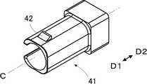
- Embodiment 1 1 and 2show the configuration of the optical connector plug according to the first embodiment.
- This optical connector plugis attached to the front end of an optical fiber (not shown) disposed on the fitting axis C, and has a cylindrical housing 11 whose both ends are open in the fitting direction along the fitting axis C.
- a ferrule 21, a spring 31, and a connecting member 41 accommodated in the housing 11are included.
- the front end of the optical fiberis held by a ferrule 21, and the tip portion of the ferrule 21 is exposed along the fitting axis C from the end of the housing 11.
- first direction D1the direction in which the tip of the ferrule 21 is exposed from the end of the housing 11 along the fitting axis C
- second direction D2the direction opposite to the first direction D1
- first direction D1the direction in which the tip of the ferrule 21 is exposed from the end of the housing 11 along the fitting axis C
- first direction D1the direction in which the tip of the ferrule 21 is exposed from the end of the housing 11 along the fitting axis C
- second direction D2the direction opposite to the first direction D1
- the direction toward the front end of the optical fiber along the optical fiber (not shown) arranged on the fitting axis Cis defined as the first direction D1.
- the ferrule 21includes a ceramic capillary 22 located on the first direction D1 side and a metal capillary holding member 23 located on the second direction D2 side of the capillary 22.
- the capillary 22has a cylindrical shape that extends in the fitting direction along the fitting axis C and is open at both ends in the fitting direction.
- the opening on the first direction D1 side of the capillary 22has a fitting axis C. Located on the top.
- the capillary holding member 23has a cylindrical shape that extends in the fitting direction along the fitting axis C and is open at both ends in the fitting direction.
- the end of the capillary 22 on the second direction D2 sideis connected to the capillary holding member 23, and the capillary 22 is held by the capillary holding member 23.
- An optical fiber(not shown) is inserted from the opening on the second direction D2 side of the capillary holding member 23, passes through the inside of the capillary holding member 23, is fixed to the inside of the capillary 22 with an adhesive or the like, and is held by the ferrule 21. However, at this time, the optical fiber may be eccentric with respect to the ferrule 21.
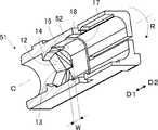
- a regular hexagonal columnar flange 24is formed at the end of the capillary holding member 23 on the first direction D1 side so as to protrude in a direction perpendicular to the fitting axis C with the fitting axis C as a center.
- the cross section of the flange 24 in the direction perpendicular to the fitting axis Chas a regular hexagonal shape centered on the fitting axis C, and six flat portions 25 are formed on the side surface of the flange 24. .
- the end face on the first direction D1 side of the flange 24has a regular hexagonal shape, and corner portions 26 are respectively formed at the six apexes of the regular hexagonal end face.
- a flange end portion 27 having a conical shape extending in the second direction D2 around the fitting shaft Cis formed at the end portion of the flange 24 on the first direction D1 side.
- an abutting surface 12 for abutting the flange end portion 27 of the flange 24 of the ferrule 21is formed inside the housing 11.
- the abutting surface 12has a regular hexagonal pyramid shape that opens in the second direction D2 around the fitting axis C.
- 5is a view of the inside of the housing 11 from a different direction with respect to FIG.
- a flange accommodating portion 13 for accommodating the flange 24 of the ferrule 21is formed in the housing 11 so as to extend from the abutting surface 12 in the second direction D2.
- the flange accommodating portion 13has a regular hexagonal cylindrical shape with the fitting axis C as the center.
- the cross section of the flange housing portion 13 in the direction perpendicular to the fitting axis Chas a regular hexagonal shape with the fitting axis C as the center, and the cross section of the flange 24 in the direction perpendicular to the fitting axis C. It is similar and slightly larger than the cross section of the flange 24.
- the flange accommodating portion 13is surrounded by six triangular side wall surfaces 14 arranged around the fitting axis C, and the six side wall surfaces 14 extend in parallel to the fitting axis C, respectively. Yes.
- Six triangular slope surfaces 16are provided on the side of the six triangular side wall surfaces 14 of the flange accommodating portion 13 in the second direction D2 via linear boundary lines 15 inclined with respect to the fitting axis C. It is connected. These six slope surfaces 16 are inclined so as to expand toward the second direction D2 along the fitting axis C, and are located on the outer side in the radial direction with respect to the fitting axis C from the flange housing portion 13. At the same time, in the direction along the fitting axis C, it is disposed within the range of the region W occupied by the flange accommodating portion 13. Each of the six slope surfaces 16 forms a single plane that continuously extends from one end to the other end of the corresponding side wall surface 14 in the circumferential direction.
- Each of the six slope surfaces 16increases in distance from the fitting axis C toward the second direction D2 from the corresponding side wall surface 14, and is viewed from the second direction D2 with the fitting axis C as the center. Further, the inclination is such that the distance from the abutting surface 12 in the second direction D2 increases as it goes in the clockwise rotation direction R.
- a spring accommodating portion 17 for accommodating the spring 31is formed in the housing 11 so as to be adjacent to the flange accommodating portion 13 on the second direction D2 side.
- the six slope surfaces 16are arranged in the range of the area W occupied by the flange accommodating portion 13 in the direction along the fitting axis C, and extend to the inside of the spring accommodating portion 17. Is configured to not.
- the connecting member 41has a shape that opens at both ends in the fitting direction along the fitting axis C, and is formed on the outer wall of the housing 11 outside the connecting member 41.
- a claw portion 42 corresponding to the through hole 18is formed.
- a spring contact portion 43is formed inside the connecting member 41 so that the end of the spring 31 on the second direction D2 side contacts.
- the spring 31 shown in FIG. 2is a so-called coil spring that extends in the fitting direction.
- the housing 11can be manufactured using resin or metal.
- the assembly of the optical connector plug according to Embodiment 1will be described.
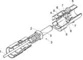
- the optical connector plug according to the first embodimentis assembled, as shown in FIG. 7, the first direction along the fitting axis C from the opening at the end of the housing 11 on the second direction D2 side.
- the ferrule 21, the spring 31, and the connecting member 41are sequentially inserted so as to go to D1.
- the amount of eccentricity of the optical fiber with respect to the ferrule 21is measured in advance, and when the ferrule 21 is inserted, the rotational position about the fitting axis C is determined in advance according to the measured amount of eccentricity.
- the spring contact portion 43 of the connecting member 41presses the end of the spring 31 on the second direction D2 side in the first direction D1, and the spring 31 advances in the first direction D1.
- the connecting member 41 and the spring 31further advance in the first direction D1
- the end of the spring 31 on the first direction D1 sidepresses the end of the flange 24 on the second direction D2 side in the first direction D1
- the ferrule 21Advance in the first direction D1.
- each of the six slope surfaces 16increases in distance from the fitting axis C toward the second direction D2 from the corresponding side wall surface 14, and in the second direction around the fitting axis C. Inclination is performed such that the distance from the abutment surface 12 in the second direction D2 increases as it goes in the clockwise rotation direction R viewed from D2. For this reason, when the six corners 26 come into contact with the six slope surfaces 16, there is a circumferential displacement in the ferrule 21 with respect to a predetermined rotational position around the fitting axis C.
- the ferrule 21advances in the first direction D1 while rotating in the counterclockwise direction of rotation as viewed from the second direction D2. That is, the ferrule 21 moves forward in the first direction D1 while correcting the positional deviation in the circumferential direction.
- the six slope surfaces 16each form a single plane. For this reason, the six corners 26 of the flange 24 can smoothly contact the six slope surfaces 16, and the flange 24 is smoothly guided in a predetermined direction.
- the ferrule 21is guided to a predetermined rotational position around the fitting axis C. Further, as shown in FIG. 2, the flange end portion 27 of the flange 24 abuts against the abutting surface 12 inside the housing 11, the flange 24 is accommodated in the flange accommodating portion 13, and a predetermined position in the fitting direction is determined. The ferrule 21 is guided. 8 is a view of the optical connector plug according to Embodiment 1 as viewed from the second direction D2, but the spring 31 and the connecting member 41 are omitted.
- the ferrule 21when inserting the ferrule 21 into the housing 11, the ferrule 21 can be surely arranged at a predetermined rotational position around the fitting axis C and at a predetermined position in the fitting direction. it can. That is, the ferrule 21 can be reliably arranged at a predetermined position in the housing 11. Further, as described above, each of the six slope surfaces 16 in the housing 11 continuously extends from one end to the other end of the corresponding side wall surface 14 in the circumferential direction. For this reason, even if the positional deviation in the circumferential direction seen from the fitting shaft C occurs in the ferrule 21 within a range in which the corner portion 26 of the flange 24 can contact the corresponding slope surface 16, The ferrule 21 can be reliably disposed at a predetermined position.
- the six slope surfaces 16are arranged in the range of the area W occupied by the flange accommodating portion 13 in the direction along the fitting axis C, and are configured not to extend into the spring accommodating portion 17 of the housing 11. Has been. For this reason, there is no possibility that the springs 31 accommodated in the spring accommodating portion 17 come into contact with the respective slope surfaces 16, and the springs 31 press the flanges 24, so that the ferrule 21 is securely placed at a predetermined position in the housing 11. Can be arranged.
- the abutting surface 12has a regular hexagonal pyramid shape that opens in the second direction D2 around the fitting axis C, and the flange end portion 27 extends in the second direction D2 around the fitting axis C. It has a conical shape. For this reason, when the flange end portion 27 abuts against the abutting surface 12, the position of the ferrule 21 in the direction orthogonal to the fitting axis C can be accurately aligned.
- the ferrule 21stops moving forward and the connecting member 41 moves forward while compressing the spring 31 in the first direction D1. Then, the claw portion 42 of the connecting member 41 is caught in the through hole 18 of the housing 11, and the connecting member 41 is connected to the second direction D2 side of the housing 11 to complete the assembly of the optical connector plug.
- the spring 31 accommodated in the spring accommodating portion 17 in the housing 11is located between the end of the flange 24 of the ferrule 21 on the second direction D2 side and the spring contact portion 43 of the connecting member 41. Further, after the assembly of the optical connector plug is completed, since the connecting member 41 is fixed to the housing 11, the spring 31 presses the ferrule 21 against the housing 11 in the first direction D1. As a result, the ferrule 21 is held in the housing 11.
- the regular hexagonal cross section in the direction orthogonal to the fitting axis C of the flange accommodating portion 13 in the housing 11is the shape of the cross section in the direction orthogonal to the fitting axis C of the flange 24 of the ferrule 21. Is slightly larger than this cross section.
- the six side wall surfaces 14 surrounding the flange accommodating portion 13extend in parallel to the fitting axis C, and correspond to the six flat portions 25 formed on the side surface of the flange 24. For this reason, the ferrule 21 is prevented from rotating in the circumferential direction around the fitting axis C with respect to the housing 11.
- the flange 24 of the ferrule 21has a regular hexagonal section centered on the fitting axis C, and the flange accommodating portion 13 in the housing 11 has a regular hexagonal section similar to the sectional shape of the flange 24.
- the present inventionis not limited to this.
- the flange 24is configured to have a regular polygonal cross section such as a regular quadrangle with the fitting axis C as the center, and the flange accommodating portion 13 is formed to have a cross sectional shape similar to the cross sectional shape of the flange 24. It may be configured.
- Each of the six slope surfaces 16 in the housing 11has a distance from the fitting shaft C that increases from the corresponding side wall surface 14 in the second direction D2, and a second centered on the fitting shaft C. You may incline so that the distance from the abutting surface 12 in the 2nd direction D2 may become large, so that it goes to the counterclockwise rotation direction seen from the direction D2. As a result, the six corners 26 of the flange 24 come into contact with the six slope surfaces 16 in the housing 11, and the flange 24 is guided by these slope surfaces 16 to rotate clockwise as viewed from the second direction D2. The ferrule 21 moves forward in the first direction D1 while rotating to R.
- the six slope surfaces 16have a triangular shape. However, in the direction along the fitting axis C, these slope surfaces are formed within the range of the region W occupied by the flange accommodating portion 13, and when the ferrule 21 is inserted, the six corner portions 26 of the flange 24 of the ferrule 21 are formed. If they contact the slope surfaces, the ferrule 21 can be reliably disposed at a predetermined position in the housing 11 regardless of the shape of the slope surfaces. For this reason, the shape of these slope surfaces is not limited to a triangular shape, and may be another shape.
- FIGS. 4 and 5show a housing 51 used for the optical connector plug of the second embodiment.
- This housing 51has six trapezoidal slope surfaces 52 formed in place of the six triangular slope surfaces 16 of the housing 11 shown in FIGS. 4 and 5 in the first embodiment.
- the configurationis the same as that of the housing 11 in the first embodiment.
- the six slope surfaces 52are arranged in the range of the region W occupied by the flange accommodating portion 13 in the direction along the fitting axis C.
- 10is a view of the inside of the housing 51 seen from a different direction with respect to FIG.
- the ferrule 21, the spring 31, and the connection member 41 in Embodiment 1are used for the optical connector plug of Embodiment 2.
- the first direction along the fitting axis C from the opening at the end of the housing 51 on the second direction D2 sideis the same as in the first embodiment.
- the ferrule 21, the spring 31, and the connecting member 41are sequentially inserted so as to go to D1.
- the ferrule 21moves forward and the six corners 26 of the flange 24 of the ferrule 21 come into contact with the six trapezoidal slope surfaces 52 in the housing 51, the flange 24 is guided by these slope surfaces 52,
- the ferrule 21moves forward in the first direction D1 while rotating in the counterclockwise rotation direction viewed from the two directions D2.
- the ferrule 21is guided to a predetermined rotational position around the fitting axis C.
- the ferrule 21is guided to a predetermined position in the fitting direction.
- the ferrule 21can be reliably arranged at a predetermined position in the housing 51.
Landscapes
- Physics & Mathematics (AREA)
- General Physics & Mathematics (AREA)
- Optics & Photonics (AREA)
- Mechanical Coupling Of Light Guides (AREA)
Abstract
Description
Translated fromJapaneseこの発明は、光ファイバの前端に取り付けられた光コネクタプラグに関する。The present invention relates to an optical connector plug attached to the front end of an optical fiber.
この種の光コネクタプラグは、一般的に、光ファイバの前端に取り付けられたフェルールと、このフェルールを収容して内部に保持する筒形状のハウジングを有している。光ファイバの前端が接着剤等によりフェルールに固定されたときに、フェルールに対して光ファイバが偏心することがあり、光コネクタプラグの嵌合時には、嵌合軸から見た周方向の位置合わせが行われている。
このため、光コネクタプラグの組立時には、嵌合軸を中心とする予め定められた回転位置にフェルールを配置することが要求される。例えば、特許文献1には、フェルールをハウジングに挿入する際に、嵌合軸を中心とする予め定められた回転位置にフェルールを案内することができる光コネクタプラグが開示されている。This type of optical connector plug generally has a ferrule attached to the front end of an optical fiber and a cylindrical housing that accommodates the ferrule and holds it inside. When the front end of the optical fiber is fixed to the ferrule with an adhesive or the like, the optical fiber may be eccentric with respect to the ferrule. Has been done.
For this reason, when assembling the optical connector plug, it is required to arrange the ferrule at a predetermined rotational position around the fitting shaft. For example, Patent Document 1 discloses an optical connector plug that can guide a ferrule to a predetermined rotational position around a fitting shaft when the ferrule is inserted into a housing.
図11に示されるように、特許文献1に記載の光コネクタプラグは、光ファイバ1の前端に取り付けられており、四角柱形状のフランジ2が形成されたフェルール3と、このフェルール3を収容するための筒形状のハウジング4を有している。ハウジング4の内部には、フランジ2の前端面が突き当たるための突き当て面5が形成されている。この突き当て面5の周囲には、4つの案内部が形成されており、それぞれの案内部に稜線6が形成されている。これらの稜線6は、光コネクタプラグの後方に向かって広がるように傾斜している。それぞれの案内部には、稜線6を境界に、第1スロープ面7と、第2スロープ面8が形成されている。As shown in FIG. 11, the optical connector plug described in Patent Document 1 is attached to the front end of the optical fiber 1, and accommodates the
フランジ2の前端面は略四角形状を有しており、この略四角形状の4つの頂点に対応する4つの角部9がフランジ2に形成されている。フェルール3をハウジング4に挿入する際に、フランジ2の4つの角部9がハウジング4内の案内部に接触し、フランジ2が案内部により案内されて嵌合軸を中心に回転しながら前進し、フランジ2の前端面が突き当て面5に突き当たることとなる。The front end surface of the
しかしながら、案内部には、稜線6を境界に、第1スロープ面7と第2スロープ面8という2つの面が形成されている。このため、フランジ2の角部9が第1スロープ面7と第2スロープ面8のどちらに接触するかで、フランジ2の回転する方向が変わってしまい、嵌合軸を中心とする予め定められた回転位置にフェルール3を配置することができないおそれがある。
また、フランジ2の4つの角部9がそれぞれ対応する案内部の稜線6に突き当たると、フランジ2が回転することも前進することもできなくなり、フランジ2の前端面が、ハウジング4内の突き当て面5に突き当たることができないおそれがある。このため、嵌合方向の予め定められた位置にフェルール3を配置することができないおそれがある。However, the guide portion is formed with two surfaces, a
Further, when the four
この発明は、このような従来の問題点を解決するためになされたもので、組立時においてハウジング内の予め定められた位置にフェルールを確実に配置することができる光コネクタプラグを提供することを目的とする。The present invention has been made to solve such a conventional problem, and provides an optical connector plug capable of reliably arranging a ferrule at a predetermined position in a housing at the time of assembly. Objective.
この発明に係る光コネクタプラグは、嵌合軸上に配置された光ファイバの前端に取り付けられ且つ光ファイバに沿って光ファイバの前端へと向かう第1方向に嵌合される光コネクタプラグであって、嵌合軸上に光ファイバの前端を挿入して保持すると共に嵌合軸を中心とする正多角形の断面形状のフランジを有するフェルールと、フェルールの第1方向側の端部が露出するようにフェルールを収容して保持する筒形状のハウジングと、ハウジングに対してフェルールを第1方向に押しつけるバネとを備え、ハウジングは、第1方向とは反対向きの第2方向を向き且つフェルールのフランジの第1方向側の端部に突き当たる突き当て面と、突き当て面から第2方向に向かって延び且つ嵌合軸を中心とする周方向に配列された複数の平面状の側壁面により囲まれると共にフェルールのフランジの断面形状と相似の断面形状を有してフランジを収容するフランジ収容部と、フランジ収容部の複数の側壁面に対応し且つ複数の側壁面の第2方向側に接続される複数のスロープ面とを有し、複数のスロープ面は、それぞれ、対応する側壁面の周方向の一端から他端まで連続して延び且つ対応する側壁面から第2方向に向かうほど嵌合軸からの距離が大きくなると共に嵌合軸を中心とする所定の回転方向に向かうほど第2方向における突き当て面からの距離が大きくなるように傾斜するものである。An optical connector plug according to the present invention is an optical connector plug that is attached to a front end of an optical fiber disposed on a fitting shaft and is fitted in a first direction along the optical fiber toward the front end of the optical fiber. Then, the front end of the optical fiber is inserted and held on the fitting shaft, and the ferrule having a regular polygonal cross-sectional flange centered on the fitting shaft and the end portion on the first direction side of the ferrule are exposed. A cylindrical housing that holds and holds the ferrule and a spring that presses the ferrule against the housing in the first direction, and the housing faces the second direction opposite to the first direction and the ferrule An abutting surface that abuts against the end of the flange in the first direction side, and a plurality of planar sides that extend from the abutting surface in the second direction and are arranged in the circumferential direction about the fitting shaft A flange housing part that is surrounded by the surface and has a cross-sectional shape similar to the cross-sectional shape of the flange of the ferrule and that accommodates the flange; A plurality of slope surfaces connected to each other, each of the slope surfaces continuously extending from one end to the other end in the circumferential direction of the corresponding side wall surface and from the corresponding side wall surface toward the second direction. As the distance from the fitting shaft increases, the distance from the abutment surface in the second direction increases as the distance from the fitting shaft increases in the predetermined rotational direction.
好ましくは、複数の側壁面は、それぞれ、嵌合軸に平行に延び、複数のスロープ面は、それぞれ、平面からなると共に嵌合軸に対して傾斜する直線状の境界線を介して対応する側壁面に接続されている。
より好ましくは、複数のスロープ面は、それぞれ、嵌合軸に沿った方向において、フランジ収容部が占める領域の範囲内に配置されている。
さらに好ましくは、ハウジングは、フランジ収容部の第2方向側に隣接して形成され且つバネを収容するバネ収容部を有する。
より好ましくは、ハウジングの第2方向側に連結され且つバネの第2方向側の端部が接触するバネ接触部を有する連結部材を備え、フランジの第2方向側の端部と連結部材のバネ接触部との間にバネが配置される。Preferably, each of the plurality of side wall surfaces extends in parallel with the fitting shaft, and each of the plurality of slope surfaces is a corresponding side through a linear boundary line that is a flat surface and is inclined with respect to the fitting shaft. Connected to the wall.
More preferably, each of the plurality of slope surfaces is disposed within a range of the region occupied by the flange accommodating portion in the direction along the fitting axis.
More preferably, the housing has a spring accommodating portion that is formed adjacent to the second direction side of the flange accommodating portion and accommodates the spring.
More preferably, it includes a connecting member that is connected to the second direction side of the housing and has a spring contact portion that comes into contact with the end of the spring in the second direction, and the end of the flange in the second direction and the spring of the connecting member A spring is disposed between the contact portion.
複数の側壁面は、それぞれ、三角形状を有し、複数のスロープ面は、それぞれ、三角形状または台形形状を有するという構成にしても良い。
また、フランジの第1方向側の端部は、円錐形状を有し、突き当て面は、多角錐形状を有するという構成にしても良い。
さらに、フェルールは、光ファイバの前端が挿入されるキャピラリと、キャピラリの第2方向側に連結されてキャピラリを保持し且つフランジが形成されたキャピラリ保持部材とを有し、キャピラリの第1方向側の端部がハウジングから露出するという構成にしてもよい。Each of the plurality of side wall surfaces may have a triangular shape, and each of the plurality of slope surfaces may have a triangular shape or a trapezoidal shape.
Moreover, you may make it the structure that the edge part by the side of the 1st direction of a flange has a cone shape, and an abutting surface has a polygonal pyramid shape.
Furthermore, the ferrule includes a capillary into which the front end of the optical fiber is inserted, and a capillary holding member that is connected to the second direction side of the capillary to hold the capillary and is formed with a flange. Alternatively, the end portion may be exposed from the housing.
この発明によれば、ハウジングは、第1方向とは反対向きの第2方向を向き且つフェルールのフランジの第1方向側の端部に突き当たる突き当て面と、突き当て面から第2方向に向かって延び且つ嵌合軸を中心とする周方向に配列された複数の平面状の側壁面により囲まれると共にフェルールのフランジの断面形状と相似の断面形状を有してフランジを収容するフランジ収容部と、フランジ収容部の複数の側壁面に対応し且つ複数の側壁面の第2方向側に接続される複数のスロープ面とを有し、複数のスロープ面は、それぞれ、対応する側壁面の周方向の一端から他端まで連続して延び且つ対応する側壁面から第2方向に向かうほど嵌合軸からの距離が大きくなると共に嵌合軸を中心とする所定の回転方向に向かうほど第2方向における突き当て面からの距離が大きくなるように傾斜するので、組立時においてハウジング内の予め定められた位置にフェルールを確実に配置することができる。According to the present invention, the housing faces the second direction opposite to the first direction and abuts against the end of the ferrule flange on the first direction side, and faces the second direction from the abutment surface. A flange accommodating portion that is surrounded by a plurality of planar side wall surfaces that extend in the circumferential direction about the fitting shaft and that has a cross-sectional shape similar to the cross-sectional shape of the flange of the ferrule and accommodates the flange A plurality of slope surfaces corresponding to the plurality of side wall surfaces of the flange housing portion and connected to the second direction side of the plurality of side wall surfaces, each of the plurality of slope surfaces being in the circumferential direction of the corresponding side wall surface The distance from the fitting shaft increases continuously from one end to the other end of the tube and from the corresponding side wall surface in the second direction, and in the second direction as the direction of rotation about the fitting shaft increases. Sudden Since inclined such that the distance from the contact surface is increased, it is possible to reliably position the ferrule in a predetermined position within the housing during assembly.
以下、この発明の実施の形態を添付図面に基づいて説明する。
実施の形態1
図1および図2に、実施の形態1に係る光コネクタプラグの構成を示す。この光コネクタプラグは、嵌合軸C上に配置された図示しない光ファイバの前端に取り付けられたものであり、嵌合軸Cに沿った嵌合方向において両端が開口した筒形状のハウジング11、このハウジング11内に収容されたフェルール21、バネ31および連結部材41を有している。
光ファイバの前端はフェルール21に保持されており、このフェルール21の先端部分が、ハウジング11の端部から嵌合軸Cに沿って露出している。
ここで、便宜上、嵌合軸Cに沿ってフェルール21の先端部分がハウジング11の端部から露出する方向を第1方向D1、第1方向D1と反対向きの方向を第2方向D2と呼ぶこととする。すなわち、嵌合軸C上に配置されている図示しない光ファイバに沿って光ファイバの前端へと向かう方向を第1方向D1としている。Embodiments of the present invention will be described below with reference to the accompanying drawings.
Embodiment 1
1 and 2 show the configuration of the optical connector plug according to the first embodiment. This optical connector plug is attached to the front end of an optical fiber (not shown) disposed on the fitting axis C, and has a
The front end of the optical fiber is held by a
Here, for convenience, the direction in which the tip of the
図3に示されるように、フェルール21は、第1方向D1側に位置するセラミックス製のキャピラリ22と、キャピラリ22の第2方向D2側に位置する金属製のキャピラリ保持部材23を有している。キャピラリ22は、嵌合軸Cに沿った嵌合方向に延びると共に嵌合方向の両端が開口した筒形状を有しており、キャピラリ22の第1方向D1側の開口部は、嵌合軸C上に位置している。As shown in FIG. 3, the
キャピラリ保持部材23は、嵌合軸Cに沿った嵌合方向に延びると共に嵌合方向の両端が開口した筒形状を有している。そして、キャピラリ22の第2方向D2側の端部は、キャピラリ保持部材23に連結され、キャピラリ22がキャピラリ保持部材23に保持されている。これにより、キャピラリ22とキャピラリ保持部材23の内部の空間が互いに連通している。
図示しない光ファイバは、キャピラリ保持部材23の第2方向D2側の開口部から挿入され、キャピラリ保持部材23の内部を通過し、キャピラリ22の内部に接着剤等により固定されてフェルール21に保持されるが、このとき、フェルール21に対して光ファイバが偏心することがある。The
An optical fiber (not shown) is inserted from the opening on the second direction D2 side of the
キャピラリ保持部材23の第1方向D1側の端部には、嵌合軸Cを中心に嵌合軸Cに直交する方向に張り出すような正六角柱形状のフランジ24が形成されている。このフランジ24の嵌合軸Cに直交する方向の断面は、嵌合軸Cを中心とする正六角形状を有しており、フランジ24の側面には、6つの平面部25が形成されている。また、フランジ24の第1方向D1側の端面は正六角形状を有しており、この正六角形状の端面の6つの頂点にそれぞれ角部26が形成されている。
フランジ24の第1方向D1側の端部には、嵌合軸Cを中心に第2方向D2に広がる円錐形状を有するフランジ端部27が形成されている。A regular hexagonal
A
図4および図5に示されるように、ハウジング11の内部には、フェルール21のフランジ24のフランジ端部27が突き当たるための突き当て面12が形成されている。この突き当て面12は、嵌合軸Cを中心に第2方向D2に開く正六角錐形状を有している。なお、図5は、図4に対して異なる方向からハウジング11の内部を見た図である。4 and 5, an abutting
また、ハウジング11の内部には、突き当て面12から第2方向D2に向かって延びるように、フェルール21のフランジ24を収容するためのフランジ収容部13が形成されている。このフランジ収容部13は、嵌合軸Cを中心とする正六角柱の筒形状を有している。フランジ収容部13の嵌合軸Cに直交する方向の断面は、嵌合軸Cを中心とする正六角形状を有しており、フランジ24の嵌合軸Cに直交する方向の断面の形状に相似し、このフランジ24の断面と比較してわずかに大きい。また、フランジ収容部13は、嵌合軸Cを中心に配列された6つの三角形状の側壁面14に囲まれており、これら6つの側壁面14は、それぞれ嵌合軸Cに平行に延びている。In addition, a
フランジ収容部13の6つの三角形状の側壁面14の第2方向D2側には、嵌合軸Cに対して傾斜する直線状の境界線15を介して、6つの三角形状のスロープ面16が接続されている。これら6つのスロープ面16は、嵌合軸Cに沿った第2方向D2に向かって広がるように傾斜しており、嵌合軸Cに対してフランジ収容部13よりも径方向の外側に位置すると共に、嵌合軸Cに沿った方向においては、フランジ収容部13が占める領域Wの範囲内に配置されている。
6つのスロープ面16は、それぞれ、対応する側壁面14の周方向の一端から他端まで連続して延びる単一の平面を形成している。また、6つのスロープ面16は、それぞれ、対応する側壁面14から第2方向D2に向かうほど嵌合軸Cからの距離が大きくなると共に、嵌合軸Cを中心とする第2方向D2から見た時計回りの回転方向Rに向かうほど第2方向D2における突き当て面12からの距離が大きくなるように傾斜している。Six triangular slope surfaces 16 are provided on the side of the six triangular side wall surfaces 14 of the
Each of the six
また、ハウジング11の内部には、フランジ収容部13の第2方向D2側に隣接するように、バネ31を収容するためのバネ収容部17が形成されている。上述したように、6つのスロープ面16は、嵌合軸Cに沿った方向において、フランジ収容部13が占める領域Wの範囲内に配置されており、バネ収容部17の内部にまで延びることがないように構成されている。Further, a
図6に示されるように、連結部材41は、嵌合軸Cに沿った嵌合方向の両端が開口する形状を有しており、連結部材41の外側には、ハウジング11の外壁に形成された貫通孔18に対応する爪部42が形成されている。また、図2に示されるように、連結部材41の内部には、バネ31の第2方向D2側の端部が接触するためのバネ接触部43が形成されている。図2に示したバネ31は、嵌合方向に延びるいわゆるコイルバネである。
なお、ハウジング11は、樹脂あるいは金属を用いて製造することができる。As shown in FIG. 6, the connecting
The
次に、実施の形態1に係る光コネクタプラグの組立について説明する。
実施の形態1に係る光コネクタプラグが組み立てられる際には、図7に示されるように、ハウジング11の第2方向D2側の端部の開口部から、嵌合軸Cに沿って第1方向D1に向かうように、フェルール21、バネ31および連結部材41が順次挿入される。フェルール21に対する光ファイバの偏心量は予め測定されており、フェルール21が挿入される際には、測定された偏心量に応じて、嵌合軸Cを中心とする回転位置が予め定められる。Next, the assembly of the optical connector plug according to Embodiment 1 will be described.
When the optical connector plug according to the first embodiment is assembled, as shown in FIG. 7, the first direction along the fitting axis C from the opening at the end of the
連結部材41が第1方向D1に前進すると、連結部材41のバネ接触部43がバネ31の第2方向D2側の端部を第1方向D1に押しつけ、バネ31が第1方向D1に前進する。さらに連結部材41とバネ31が第1方向D1に前進すると、バネ31の第1方向D1側の端部がフランジ24の第2方向D2側の端部を第1方向D1に押しつけ、フェルール21が第1方向D1に前進する。When the connecting
フェルール21が前進してフランジ24がハウジング11内のフランジ収容部13に達すると、フランジ24の6つの角部26がハウジング11内の6つのスロープ面16に接触する。
前述したように、6つのスロープ面16は、それぞれ、対応する側壁面14から第2方向D2に向かうほど嵌合軸Cからの距離が大きくなると共に、嵌合軸Cを中心とする第2方向D2から見た時計回りの回転方向Rに向かうほど第2方向D2における突き当て面12からの距離が大きくなるように傾斜している。このため、6つの角部26が6つのスロープ面16に接触したときに、嵌合軸Cを中心とする予め定められた回転位置に対し、周方向の位置ズレがフェルール21に生じている場合、第2方向D2から見た反時計回りの回転方向にフェルール21が回転しながら第1方向D1に前進する。すなわち、フェルール21が周方向の位置ズレを修正しながら第1方向D1に前進する。When the
As described above, each of the six
また、前述したように、6つのスロープ面16は、それぞれ単一の平面を形成している。このため、フランジ24の6つの角部26が、6つのスロープ面16に滑らかに接触することができると共に、フランジ24が予め定められた方向に円滑に案内されることとなる。As described above, the six
そして、図8に示されるように、嵌合軸Cを中心とする予め定められた回転位置にフェルール21が案内される。さらに、図2に示されるように、フランジ24のフランジ端部27がハウジング11の内部の突き当て面12に突き当たり、フランジ24がフランジ収容部13に収容され、嵌合方向の予め定められた位置にフェルール21が案内される。
なお、図8は実施の形態1に係る光コネクタプラグを第2方向D2から見た図であるが、バネ31と連結部材41が省略されている。Then, as shown in FIG. 8, the
8 is a view of the optical connector plug according to Embodiment 1 as viewed from the second direction D2, but the
従って、フェルール21をハウジング11に挿入する際に、嵌合軸Cを中心とする予め定められた回転位置、および、嵌合方向の予め定められた位置に、フェルール21を確実に配置することができる。すなわち、ハウジング11内の予め定められた位置にフェルール21を確実に配置することができる。
また、前述したように、ハウジング11内の6つのスロープ面16は、それぞれ、対応する側壁面14の周方向の一端から他端まで連続して延びている。このため、フランジ24の角部26が対応するスロープ面16に接触することができる範囲内で、嵌合軸Cから見た周方向の位置ズレがフェルール21に生じていたとしても、ハウジング11内の予め定められた位置にフェルール21を確実に配置することができる。
また、6つのスロープ面16が、嵌合軸Cに沿った方向において、フランジ収容部13が占める領域Wの範囲内に配置され、ハウジング11のバネ収容部17の内部にまで延びないように構成されている。このため、バネ収容部17に収容されたバネ31がそれぞれのスロープ面16に接触するおそれがなく、バネ31がフランジ24を押しつけて、ハウジング11内の予め定められた位置にフェルール21を確実に配置することができる。Therefore, when inserting the
Further, as described above, each of the six
Further, the six
さらに、前述したように、突き当て面12が嵌合軸Cを中心に第2方向D2に開く正六角錐形状を有し、フランジ端部27が嵌合軸Cを中心に第2方向D2に広がる円錐形状を有している。このため、フランジ端部27が突き当て面12に突き当たる際に、フェルール21の嵌合軸Cに直交する方向の位置を精度良く合わせることができる。Furthermore, as described above, the abutting
フランジ24のフランジ端部27がハウジング11内の突き当て面12に突き当たると、フェルール21の前進が止まり、連結部材41がバネ31を第1方向D1に圧縮しながら前進する。そして、連結部材41の爪部42がハウジング11の貫通孔18に引っ掛かり、連結部材41がハウジング11の第2方向D2側に連結されて光コネクタプラグの組立が完了する。When the
ハウジング11内のバネ収容部17に収容されているバネ31は、フェルール21のフランジ24の第2方向D2側の端部と連結部材41のバネ接触部43の間に位置している。さらに、光コネクタプラグの組立が完了した後は、連結部材41がハウジング11に固定されているため、バネ31がハウジング11に対してフェルール21を第1方向D1に押しつける状態となる。これにより、フェルール21がハウジング11に保持される。The
また、前述したように、ハウジング11内のフランジ収容部13の嵌合軸Cに直交する方向の正六角形状の断面は、フェルール21のフランジ24の嵌合軸Cに直交する方向の断面の形状に相似し、この断面と比較してわずかに大きい。フランジ収容部13を囲む6つの側壁面14は、それぞれ嵌合軸Cに平行に延びており、フランジ24の側面に形成された6つの平面部25に対応している。このため、フェルール21がハウジング11に対して嵌合軸Cを中心とする周方向に回転することが防止されている。Further, as described above, the regular hexagonal cross section in the direction orthogonal to the fitting axis C of the
なお、フェルール21のフランジ24は、嵌合軸Cを中心とする正六角形状の断面を有し、ハウジング11内のフランジ収容部13は、このフランジ24の断面形状に相似する正六角形状の断面を有していたが、これに限られるものではない。例えば、嵌合軸Cを中心とする正四角形状等の正多角形状の断面を有するようにフランジ24を構成し、このフランジ24の断面形状に相似する断面形状を有するようにフランジ収容部13を構成しても良い。The
また、ハウジング11内の6つのスロープ面16は、それぞれ、対応する側壁面14から第2方向D2に向かうほど嵌合軸Cからの距離が大きくなると共に、嵌合軸Cを中心とする第2方向D2から見た反時計回りの回転方向に向かうほど第2方向D2における突き当て面12からの距離が大きくなるように傾斜していても良い。これにより、フランジ24の6つの角部26がハウジング11内の6つのスロープ面16に接触し、フランジ24がこれらのスロープ面16により案内されて、第2方向D2から見た時計回りの回転方向Rにフェルール21が回転しながら第1方向D1に前進することとなる。Each of the six
実施の形態2
実施の形態1では、6つのスロープ面16が三角形状を有していた。しかし、嵌合軸Cに沿った方向において、フランジ収容部13が占める領域Wの範囲内にこれらのスロープ面が形成されて、フェルール21の挿入時にフェルール21のフランジ24の6つの角部26がそれぞれスロープ面に接触すれば、これらのスロープ面の形状に関わらず、ハウジング11内の予め定められた位置にフェルール21を確実に配置することができる。このため、これらのスロープ面の形状は三角形状に限られず、他の形状であっても良い。
In the first embodiment, the six
図9および図10に、実施の形態2の光コネクタプラグに用いられるハウジング51を示す。このハウジング51は、実施の形態1における図4および図5に示したハウジング11の6つの三角形状のスロープ面16の代わりに、6つの台形形状のスロープ面52が形成されたものであり、これらのスロープ面52以外は実施の形態1におけるハウジング11と同様の構成を有している。6つのスロープ面52は、嵌合軸Cに沿った方向においてフランジ収容部13が占める領域Wの範囲内に配置されている。なお、図10は、図9に対して異なる方向からハウジング51の内部を見た図である。
なお、実施の形態2の光コネクタプラグには、実施の形態1におけるフェルール21、バネ31および連結部材41が用いられる。9 and 10 show a
In addition, the
実施の形態2に係る光コネクタプラグが組み立てられる際には、実施の形態1と同様に、ハウジング51の第2方向D2側の端部の開口部から、嵌合軸Cに沿って第1方向D1に向かうように、フェルール21、バネ31および連結部材41が順次挿入される。そして、フェルール21が前進し、フェルール21のフランジ24の6つの角部26がハウジング51内の6つの台形形状のスロープ面52に接触すると、フランジ24がこれらのスロープ面52により案内されて、第2方向D2から見た反時計回りの回転方向にフェルール21が回転しながら第1方向D1に前進する。
これにより、嵌合軸Cを中心とする予め定められた回転位置にフェルール21が案内される。さらに、フランジ24のフランジ端部27がハウジング51の内部の突き当て面12に突き当たり、嵌合方向の予め定められた位置にフェルール21が案内される。
このように、それぞれのスロープ面52が台形形状を有していても、ハウジング51内の予め定められた位置にフェルール21を確実に配置することができる。When the optical connector plug according to the second embodiment is assembled, the first direction along the fitting axis C from the opening at the end of the
As a result, the
Thus, even if each
1 光ファイバ、2,24 フランジ、3,21 フェルール、4,11,51 ハウジング、5,12 突き当て面、6 稜線、7 第1スロープ面、8 第2スロープ面、9,26 角部、13 フランジ収容部、14 側壁面、15 境界線、16,52 スロープ面、17 バネ収容部、18 貫通孔、22 キャピラリ、23 キャピリ保持部材、25 平面部、27 フランジ端部、31 バネ、41 連結部材、42 爪部、43 バネ接触部、C 嵌合軸、D1,D2,R 方向、W 領域。1 optical fiber, 2,24 flange, 3,21 ferrule, 4,11,51 housing, 5,12 abutment surface, 6 ridgeline, 7 first slope surface, 8 second slope surface, 9,26 corner, 13 Flange housing part, 14 side wall surface, 15 boundary line, 16, 52 slope surface, 17 spring housing part, 18 through hole, 22 capillary, 23 capillary holding member, 25 flat surface part, 27 flange end part, 31 spring, 41 connecting
Claims (8)
Translated fromJapanese前記嵌合軸上に前記光ファイバの前端を挿入して保持すると共に前記嵌合軸を中心とする正多角形の断面形状のフランジを有するフェルールと、
前記フェルールの前記第1方向側の端部が露出するように前記フェルールを収容して保持する筒形状のハウジングと、
前記ハウジングに対して前記フェルールを前記第1方向に押しつけるバネと
を備え、
前記ハウジングは、
前記第1方向とは反対向きの第2方向を向き且つ前記フェルールの前記フランジの前記第1方向側の端部に突き当たる突き当て面と、
前記突き当て面から前記第2方向に向かって延び且つ前記嵌合軸を中心とする周方向に配列された複数の平面状の側壁面により囲まれると共に前記フェルールの前記フランジの断面形状と相似の断面形状を有して前記フランジを収容するフランジ収容部と、
前記フランジ収容部の前記複数の側壁面に対応し且つ前記複数の側壁面の前記第2方向側に接続される複数のスロープ面と
を有し、前記複数のスロープ面は、それぞれ、対応する前記側壁面の周方向の一端から他端まで連続して延び且つ対応する前記側壁面から前記第2方向に向かうほど前記嵌合軸からの距離が大きくなると共に前記嵌合軸を中心とする所定の回転方向に向かうほど前記第2方向における前記突き当て面からの距離が大きくなるように傾斜することを特徴とする光コネクタプラグ。An optical connector plug attached to a front end of an optical fiber disposed on a fitting shaft and fitted in a first direction along the optical fiber toward the front end of the optical fiber;
A ferrule having a regular polygonal cross-sectional flange centered on the fitting shaft while inserting and holding the front end of the optical fiber on the fitting shaft;
A cylindrical housing that holds and holds the ferrule such that an end of the ferrule on the first direction side is exposed;
A spring that presses the ferrule against the housing in the first direction;
The housing is
An abutting surface that faces a second direction opposite to the first direction and abuts against an end of the ferrule on the first direction side of the flange;
It is similar to the cross-sectional shape of the flange of the ferrule and is surrounded by a plurality of planar side wall surfaces extending in the second direction from the abutting surface and arranged in the circumferential direction around the fitting shaft. A flange housing portion having a cross-sectional shape and housing the flange;
A plurality of slope surfaces corresponding to the plurality of side wall surfaces of the flange accommodating portion and connected to the second direction side of the plurality of side wall surfaces, and the plurality of slope surfaces respectively corresponding to the plurality of slope surfaces The distance from the fitting shaft increases continuously from one end to the other end in the circumferential direction of the side wall surface and moves from the corresponding side wall surface to the second direction. The optical connector plug is inclined such that the distance from the abutting surface in the second direction increases as it goes in the rotation direction.
前記複数のスロープ面は、それぞれ、平面からなると共に前記嵌合軸に対して傾斜する直線状の境界線を介して対応する前記側壁面に接続されている請求項1に記載の光コネクタプラグ。Each of the plurality of side wall surfaces extends parallel to the fitting shaft,
2. The optical connector plug according to claim 1, wherein each of the plurality of slope surfaces is a flat surface and is connected to the corresponding side wall surface via a linear boundary line inclined with respect to the fitting shaft.
前記フランジの前記第2方向側の端部と前記連結部材の前記バネ接触部との間に前記バネが配置される請求項4に記載の光コネクタプラグ。A connecting member having a spring contact portion that is connected to the second direction side of the housing and contacts an end portion of the spring on the second direction side;
The optical connector plug according to claim 4, wherein the spring is disposed between an end of the flange on the second direction side and the spring contact portion of the connecting member.
前記複数のスロープ面は、それぞれ、三角形状または台形形状を有する請求項3~5のいずれか一項に記載の光コネクタプラグ。Each of the side wall surfaces has a triangular shape,
The optical connector plug according to any one of claims 3 to 5, wherein each of the plurality of slope surfaces has a triangular shape or a trapezoidal shape.
前記突き当て面は、多角錐形状を有する請求項1~6のいずれか一項に記載の光コネクタプラグ。An end of the flange on the first direction side has a conical shape,
The optical connector plug according to any one of claims 1 to 6, wherein the abutting surface has a polygonal pyramid shape.
前記キャピラリの前記第1方向側の端部が前記ハウジングから露出する請求項1~7のいずれか一項に記載の光コネクタプラグ。The ferrule includes a capillary into which a front end of the optical fiber is inserted, and a capillary holding member that is connected to the second direction side of the capillary to hold the capillary and is formed with the flange.
The optical connector plug according to any one of claims 1 to 7, wherein an end of the capillary in the first direction is exposed from the housing.
Applications Claiming Priority (2)
| Application Number | Priority Date | Filing Date | Title |
|---|---|---|---|
| JP2016125761AJP6247721B1 (en) | 2016-06-24 | 2016-06-24 | Optical connector plug |
| JP2016-125761 | 2016-06-24 |
Publications (1)
| Publication Number | Publication Date |
|---|---|
| WO2017221480A1true WO2017221480A1 (en) | 2017-12-28 |
Family
ID=60659023
Family Applications (1)
| Application Number | Title | Priority Date | Filing Date |
|---|---|---|---|
| PCT/JP2017/010668CeasedWO2017221480A1 (en) | 2016-06-24 | 2017-03-16 | Optical connector plug |
Country Status (2)
| Country | Link |
|---|---|
| JP (1) | JP6247721B1 (en) |
| WO (1) | WO2017221480A1 (en) |
Families Citing this family (1)
| Publication number | Priority date | Publication date | Assignee | Title |
|---|---|---|---|---|
| US20240219647A1 (en)* | 2022-12-31 | 2024-07-04 | Ppc Broadband, Inc. | Optical fiber connector configured to be tuned so as to minimize signal transmission loss |
Citations (8)
| Publication number | Priority date | Publication date | Assignee | Title |
|---|---|---|---|---|
| US5588079A (en)* | 1995-02-17 | 1996-12-24 | Nec Corporation | Optical connector |
| JP2001147344A (en)* | 1999-10-06 | 2001-05-29 | Lucent Technol Inc | Optical connector having housing assembly containing polyphenyl sulfone |
| JP2006267649A (en)* | 2005-03-24 | 2006-10-05 | Seikoh Giken Co Ltd | Optical connector |
| US7201518B2 (en)* | 2004-04-14 | 2007-04-10 | Adc Telecommunications, Inc. | Fiber optic connector and method |
| JP2009237515A (en)* | 2008-03-25 | 2009-10-15 | Adamant Kogyo Co Ltd | Connector housing and optical connector |
| US7891883B2 (en)* | 2002-01-30 | 2011-02-22 | Adc Telecommunications, Inc. | Fiber optic connector and method |
| JP5181020B2 (en)* | 2008-04-28 | 2013-04-10 | アダマンド工業株式会社 | Optical connector housing and optical connector |
| JP2013522679A (en)* | 2010-03-16 | 2013-06-13 | オーエフエス ファイテル,エルエルシー | Single core connector for multi-core fiber optic cable |
- 2016
- 2016-06-24JPJP2016125761Apatent/JP6247721B1/ennot_activeExpired - Fee Related
- 2017
- 2017-03-16WOPCT/JP2017/010668patent/WO2017221480A1/ennot_activeCeased
Patent Citations (8)
| Publication number | Priority date | Publication date | Assignee | Title |
|---|---|---|---|---|
| US5588079A (en)* | 1995-02-17 | 1996-12-24 | Nec Corporation | Optical connector |
| JP2001147344A (en)* | 1999-10-06 | 2001-05-29 | Lucent Technol Inc | Optical connector having housing assembly containing polyphenyl sulfone |
| US7891883B2 (en)* | 2002-01-30 | 2011-02-22 | Adc Telecommunications, Inc. | Fiber optic connector and method |
| US7201518B2 (en)* | 2004-04-14 | 2007-04-10 | Adc Telecommunications, Inc. | Fiber optic connector and method |
| JP2006267649A (en)* | 2005-03-24 | 2006-10-05 | Seikoh Giken Co Ltd | Optical connector |
| JP2009237515A (en)* | 2008-03-25 | 2009-10-15 | Adamant Kogyo Co Ltd | Connector housing and optical connector |
| JP5181020B2 (en)* | 2008-04-28 | 2013-04-10 | アダマンド工業株式会社 | Optical connector housing and optical connector |
| JP2013522679A (en)* | 2010-03-16 | 2013-06-13 | オーエフエス ファイテル,エルエルシー | Single core connector for multi-core fiber optic cable |
Also Published As
| Publication number | Publication date |
|---|---|
| JP2017227843A (en) | 2017-12-28 |
| JP6247721B1 (en) | 2017-12-13 |
Similar Documents
| Publication | Publication Date | Title |
|---|---|---|
| CA2613658C (en) | Optical connector excellent in maintenance of a connected state | |
| JP5702884B1 (en) | Optical connector plug | |
| JP6334986B2 (en) | Ball spline | |
| JP7047221B2 (en) | Optical connector plug and optical connector plug connection structure | |
| KR20150092458A (en) | Lens Module | |
| JP3966626B2 (en) | Endoscopic optical system with rod lenses separated by a spacer tube | |
| JPWO2019044079A1 (en) | Connector plug, optical connector and optical connection structure | |
| JP2018081144A (en) | Optical connector | |
| WO2017221480A1 (en) | Optical connector plug | |
| EP2981723A1 (en) | Tabbed washer for a bearing assembly | |
| JP2006284789A (en) | Lens barrel | |
| JP5862517B2 (en) | Lens barrel | |
| WO2018220875A1 (en) | Assembly set | |
| JP4793353B2 (en) | Protector and fluid filter using the same | |
| JP6473578B2 (en) | Optical connector | |
| JP7077159B2 (en) | Spring assembly | |
| JP2007268062A (en) | Board case for gaming machines | |
| JP5722816B2 (en) | Connecting joints, alignment members and segments | |
| CN102227574A (en) | one-way clutch | |
| US20180181160A1 (en) | Lever device | |
| EP4369067A1 (en) | Optical connector | |
| JP2006177454A (en) | Connecting structure with knock pin | |
| JP2024148331A (en) | Fitting structure | |
| JP4150753B1 (en) | Mechanical splice | |
| JP2023100088A (en) | Connection structure |
Legal Events
| Date | Code | Title | Description |
|---|---|---|---|
| 121 | Ep: the epo has been informed by wipo that ep was designated in this application | Ref document number:17814952 Country of ref document:EP Kind code of ref document:A1 | |
| NENP | Non-entry into the national phase | Ref country code:DE | |
| 122 | Ep: pct application non-entry in european phase | Ref document number:17814952 Country of ref document:EP Kind code of ref document:A1 |