WO2017202042A1 - Balloon catheter provided with flexible connecting part between tip and balloon - Google Patents
Balloon catheter provided with flexible connecting part between tip and balloonDownload PDFInfo
- Publication number
- WO2017202042A1 WO2017202042A1PCT/CN2017/071342CN2017071342WWO2017202042A1WO 2017202042 A1WO2017202042 A1WO 2017202042A1CN 2017071342 WCN2017071342 WCN 2017071342WWO 2017202042 A1WO2017202042 A1WO 2017202042A1
- Authority
- WO
- WIPO (PCT)
- Prior art keywords
- head end
- balloon
- flexible connecting
- connecting portion
- tube
- Prior art date
- Legal status (The legal status is an assumption and is not a legal conclusion. Google has not performed a legal analysis and makes no representation as to the accuracy of the status listed.)
- Ceased
Links
Images


Classifications
- A—HUMAN NECESSITIES
- A61—MEDICAL OR VETERINARY SCIENCE; HYGIENE
- A61F—FILTERS IMPLANTABLE INTO BLOOD VESSELS; PROSTHESES; DEVICES PROVIDING PATENCY TO, OR PREVENTING COLLAPSING OF, TUBULAR STRUCTURES OF THE BODY, e.g. STENTS; ORTHOPAEDIC, NURSING OR CONTRACEPTIVE DEVICES; FOMENTATION; TREATMENT OR PROTECTION OF EYES OR EARS; BANDAGES, DRESSINGS OR ABSORBENT PADS; FIRST-AID KITS
- A61F2/00—Filters implantable into blood vessels; Prostheses, i.e. artificial substitutes or replacements for parts of the body; Appliances for connecting them with the body; Devices providing patency to, or preventing collapsing of, tubular structures of the body, e.g. stents
- A61F2/95—Instruments specially adapted for placement or removal of stents or stent-grafts
- A61F2/958—Inflatable balloons for placing stents or stent-grafts
- A—HUMAN NECESSITIES
- A61—MEDICAL OR VETERINARY SCIENCE; HYGIENE
- A61M—DEVICES FOR INTRODUCING MEDIA INTO, OR ONTO, THE BODY; DEVICES FOR TRANSDUCING BODY MEDIA OR FOR TAKING MEDIA FROM THE BODY; DEVICES FOR PRODUCING OR ENDING SLEEP OR STUPOR
- A61M25/00—Catheters; Hollow probes
- A61M25/0021—Catheters; Hollow probes characterised by the form of the tubing
- A—HUMAN NECESSITIES
- A61—MEDICAL OR VETERINARY SCIENCE; HYGIENE
- A61M—DEVICES FOR INTRODUCING MEDIA INTO, OR ONTO, THE BODY; DEVICES FOR TRANSDUCING BODY MEDIA OR FOR TAKING MEDIA FROM THE BODY; DEVICES FOR PRODUCING OR ENDING SLEEP OR STUPOR
- A61M25/00—Catheters; Hollow probes
- A61M25/0043—Catheters; Hollow probes characterised by structural features
- A61M25/0054—Catheters; Hollow probes characterised by structural features with regions for increasing flexibility
- A—HUMAN NECESSITIES
- A61—MEDICAL OR VETERINARY SCIENCE; HYGIENE
- A61M—DEVICES FOR INTRODUCING MEDIA INTO, OR ONTO, THE BODY; DEVICES FOR TRANSDUCING BODY MEDIA OR FOR TAKING MEDIA FROM THE BODY; DEVICES FOR PRODUCING OR ENDING SLEEP OR STUPOR
- A61M25/00—Catheters; Hollow probes
- A61M25/10—Balloon catheters
Definitions
- the inventionrelates to the technical field of medical instruments, in particular to a balloon catheter with a flexible connecting portion between a head end and a balloon.
- PCIPercutaneous Coronary Intervention
- the head end of the currently used balloon catheteris a short conical shape that fits the end of the inner tube and directly abuts the balloon.
- This designis beneficial to the delivery of the balloon catheter thrust. Conducive to the balloon catheter through the stenotic lesion or the site of the chronic occlusion lesion that has just opened the guidewire, but for the vessel that is tortuous, the stenosis is not heavy, and the vessel that has been implanted and needs to be post-expanded, when the balloon catheter When the head end passes, because the head end is less flexible, it is difficult to change direction along the curved shape of the blood vessel in time, and the head end may resist the blood vessel or the bracket, causing damage.
- the head end of the prior art balloon catheterhas a small conical shape, and this design is advantageous for the balloon catheter to pass through a narrow lesion or a chronic occlusion of the guide wire just opened.
- Lesionfor a posterior dilatation balloon catheter, since it is primarily used for posterior expansion of the stent placed in the vessel so that the stent is fully expanded and snug against the medial side of the vessel if the posterior balloon is expanded
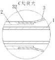
- the endis designed to conform to the conical shape of the pre-expanded balloon catheter, as shown in Figure 2, with a smaller flat end at the forward end of the catheter tip, the catheter being delivered to the stent along the guidewire
- the flat end face of the front end of the head endtends to bear against the stent beam, which makes the balloon catheter difficult to pass.
- the stentmay be deformed and cause a thrombus. Therefore, the head end structure of the balloon catheter needs to be improved to make it correct.
- the stentis post-expanded, its passability is not affected by the stent beam.
- the object of the present inventionis to provide a balloon catheter with a flexible connecting portion between the head end and the balloon, which can be deformed in a timely manner along the blood vessel, without being affected by the mesh or the stent beam, and facilitating post-expansion. The process goes smoothly and reduces the risk.
- a balloon catheter having a flexible connecting portion between the head end and the ballooncomprising an inner tube, an outer tube, a balloon and a head end, the inner tube is disposed in the outer tube, and the guide wire is passed through the inner tube, the ball a sleeve is disposed at a distal end of the inner tube, and one end of the balloon is connected to the outer tube, the other end is connected to the inner tube, and the rear side of the head end is provided with a flexible connecting portion, the inner tube The distal end is extended from the balloon and connected to the flexible connecting portion, and the flexible connecting portion is bent in conformity with the shape of the blood vessel after entering the blood vessel.
- the head endis tapered, and an outer diameter of the flexible connecting portion is greater than, equal to, or smaller than a maximum outer diameter of the head end.
- the front side of the head endis provided with a convex portion, the maximum outer diameter of the convex portion is larger than the outer diameter of the remaining portion of the head end, and the inner side wall and the outer side wall of the front side of the head end pass the
- the convex portionis in transitional engagement, the outer surface of the convex portion is a smooth surface, or the side of the convex portion connected to the inner wall of the head end is inclined toward the rear side of the head end.
- the front end of the head endis provided with a different convex portion, or only a part of the outer surface of the front end of the front end is provided with a convex portion.
- the rear side of the protrusion of the head endis provided with a connecting rod, and the head end is connected to the flexible connecting portion through the connecting rod.
- the front end of the head endis provided with a gradually narrowing transition surface, and the inner hole wall and the outer side wall at the outlet of the head end are connected by the transition surface, the transition surface is a smooth surface, or the transition
- the side of the face that is connected to the inner wall of the head endis a face that is inclined toward the rear side of the head end.
- the end of the balloonis provided with a connecting tube, and the balloon is fitted on the inner tube through the connecting tube, and the diameters of the flexible connecting portion and the head end are both larger than the diameter of the connecting tube of the balloon.
- the rear side of the head endis disposed in a tapered shape or a sloped surface; the initial shape of the flexible connecting portion is curved, and the flexible connecting portion is further curved in conformity with the shape of the blood vessel after entering the blood vessel.
- the radial end section of the head endis circular or polygonal, and the flexible connecting portion has a circular cross section or a polygonal shape.
- the flexible connecting portion and the head endare of a split structure or an integral structure.
- the present inventionprovides a flexible connecting portion between the head end and the balloon, which enables the head end to be deformed in a timely manner along the blood vessel, so that the passing performance is not affected by the blood vessel bending or the bracket beam.
- the head end of the present inventionis provided with a convex portion or a transition surface so that there is no flat end surface on the front side of the head end, and the balloon catheter is not obstructed by the stent beam when it is in contact with the blood vessel support, and can smoothly slide over the stent Beam.
- FIG. 1is a schematic view showing the distal structure of a balloon catheter in the prior art
- FIG. 2is an enlarged view of A in Figure 1
- Embodiment 1 of the present inventionis a schematic structural view of Embodiment 1 of the present invention.
- Figure 4is an enlarged view of B in Figure 3
- FIG. 5is an enlarged view of the portion C in Figure 3,
- Figure 6is an enlarged view of the portion D in Figure 3,
- FIG. 7is an enlarged view of E in Figure 3,
- FIG. 8is a schematic structural view of a distal end according to Embodiment 2 of the present invention.
- FIG. 9is a schematic structural view of a distal end according to Embodiment 3 of the present invention.
- FIG. 10is a schematic structural view of a distal end according to Embodiment 4 of the present invention.
- FIG. 11is a schematic structural view of a distal end according to Embodiment 5 of the present invention.
- FIG. 12is a schematic structural view of a distal end according to Embodiment 6 of the present invention.
- FIG. 13is a schematic structural view of a distal end according to Embodiment 7 of the present invention.
- FIG. 14is a schematic structural view of a distal end according to Embodiment 8 of the present invention.
- Embodiment 9is a schematic structural view of a distal end of Embodiment 9 of the present invention.
- FIG 16is a schematic view of the present invention when passing through a guide wire (OTW) type balloon catheter
- Figure 17is a schematic view showing a structure when the head end is provided with a convex portion.
- Figure 18is a schematic view showing another structure when the head end is provided with a convex portion.
- Figure 19is a schematic view showing another structure when the head end is provided with a convex portion.
- Figure 20is an axial view of the head end with a raised portion
- Figure 21is a schematic view showing a structure when the head end is provided with an asymmetric convex portion.
- Figure 22is a schematic view showing another structure when the head end is provided with an asymmetric convex portion.
- Figure 23is an axial view of the head end with an asymmetric projection.
- Figure 24is a schematic view showing a structure when only a part of the boss is provided at the head end.
- Figure 25is a schematic view showing another structure when only a part of the boss is provided at the head end.
- Figure 26is a schematic view showing a state in which the axial section of the head end projection is polygonal.
- Figure 27is a schematic view showing a radial section of the head end boss being polygonal.
- Figure 28is a schematic view showing the structure of the head end wall thickened.
- Figure 29is a schematic view showing another structure when the wall thickness of the head end is thickened.
- Figure 30is an axial view of the head end wall thickened
- Figure 31is a schematic view showing another structure when the thickness of the head end is thickened.
- Figure 32is an axial end view of the head end of Figure 31
- Figure 33is a schematic view showing a structure in which the thickness of the head end is thickened and the back side is provided with a tapered surface.
- Figure 34is a schematic view showing another structure in which the thickness of the head end is thickened and the back side is provided with a tapered surface.
- Figure 35is a schematic view showing another structure in which the thickness of the head end is thickened and the back side is provided with a tapered surface.
- Figure 36is a schematic view showing the edge of the axial section being polygonal when the thickness of the head end is thick.
- Fig. 37is a schematic view showing a case where the radial thickness of the head end is thick and the cross section is polygonal.
- 1is the inner tube
- 11is the head end
- 111is the connecting rod
- 12is the guide wire outlet
- 13is the developing ring
- 2is the outer tube
- 3is the balloon
- 31is the liquid passing chamber
- 32is the connecting tube
- 4For the flexible joint, 41 is the transition bevel, 5 is the joint, 6 is the conduit, 7 is the strain relief tube, and 8 is the flat end face.
- the present inventioncomprises an inner tube 1, an outer tube 2, a balloon 3, a joint 5, a catheter 6 and a strain relief tube 7, wherein the inner tube 1 is disposed in the outer tube 2, and the inner tube 1 is internally connected.
- the balloon 3is sleeved on the distal end of the inner tube 1 (the distal end is the end away from the operator, that is, the free end), and One end of the balloon 3 is connected to the outer tube 2, and the other end is connected to the inner tube 1.
- the inside of the balloon 3is a liquid passage chamber 31, as shown in Figs.
- a plurality of developing rings 13are disposed outside the inner tube 1 in the capsule 3, and the position of the developing ring 13 can be displayed by a corresponding instrument, thereby helping the operator to understand the position of the balloon, as shown in Fig. 6, near the outer tube 2.
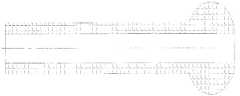
- a conduit 6is provided in the end (the proximal end, that is, an end near the operator), and the conduit 6 is disposed outside the inner tube 1, as shown in FIG. 3, the proximal end of the conduit 6 is connected to the joint 5,
- a strain relief tube 7is disposed on the joint 5, and the strain relief tube 7 is fastened to the distal end of the joint 5, and the strain relief tube 7 is used to avoid stress concentration to improve the use of the balloon catheter. Life.
- the balloon 3is formed by pressure heating and blow molding, and the nylon pipe having an inner diameter of 0.3 to 1.5 mm, an outer diameter of 0.6 to 2.0 mm, and a length of 400 to 600 mm is at a pressure of 300 to 600 PSI and 160 to 220 degrees Celsius. Under the condition of blowing, a cylinder having a diameter of 2.0 to 5.0 mm and a length of 5.0 to 30.0 mm is obtained as a main body of the balloon 3, and as shown in Figs. 5 and 7, a connection is provided at both ends of the balloon 3.
- the tube 32has an outer diameter of 0.60 to 1.02 mm and a length of 1.0 to 10.0 mm, and the balloon 3 is respectively fitted on the inner tube 1 and the outer tube 2 through the connecting tubes 32 at both ends, thereby realizing
- the inner tube 1 and the outer tube 2are connected, and a liquid passage chamber 31 is formed between the balloon 3 and the inner tube 1, and the liquid passage chamber 31 can be inflated after the developer is introduced, thereby expanding the bracket.
- the outer tube 2is made of nylon, polyethylene, polypropylene or block polyamide, and has an extrusion temperature of 250 to 1600 mm and an outer diameter of 0.76 at an extrusion temperature of 200 to 280 degrees Celsius and a cooling temperature of 15 to 40 degrees Celsius.
- the outer tube 2is obtained by a pipe having a thickness of 0.86 mm and a thickness of 0.04 to 0.14 mm.
- the inner tube 1is made of nylon, polyethylene, polypropylene or block polyamide, and is made under the same conditions as the outer tube 2, and has a length of 250 to 1600 mm and an outer diameter of 0.50 to 0.61 mm.
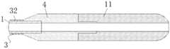
- the distal end of the inner tube 1is extended from the balloon 3 and connected to the head end 11 through a flexible connecting portion 4.
- the flexible connecting portion 4is under an external force. Will conform to the curvature of the blood vessel, so as to effectively prevent the head end 11 from supporting the stent beam, ensuring the passage of the catheter, the flexible connection
- the joint 4is made of nylon, polyethylene, polypropylene or block polyamide.
- the flexible connecting portion 4 and the head end 11can be designed as a component body structure, or can be designed as a unitary structure.
- the flexible connecting portion 4may be made of nylon, polyethylene, polypropylene, block polyamide or polyurethane and extruded by extrusion at an extrusion temperature of 200. Extruded tube at 280 ° C and cooling temperature of 15 to 40 ° C. The length is 0 to 20 mm, the outer diameter is 0.50 to 2 mm, and the thickness is 0.07 to 0.82 mm.
- the flexible connecting portion 4 and the head end 11are of a unitary structure
- the flexible connecting portion 4 and the head end 11are made of nylon, polyethylene, polypropylene, block polyamide or polyurethane, and are injection molded in a corresponding shape.
- the moldis injection molded in one piece.
- the head end 11can be designed to be tapered as needed, and as shown in FIGS. 1 and 2, if the rear dilatation balloon catheter is also designed to be tapered, since the front end 11 has a small flat end surface 8, When the balloon catheter is fed into the stent along the guide wire, the flat end surface 8 tends to bear against the stent beam and the catheter cannot pass. To solve this problem, the structure of the head end 11 needs to be improved.
- this embodimentis a quick exchange type balloon catheter, and a guide wire outlet 12 is provided in the middle of the catheter.
- a tapered tip end 11is employed, and the head end 11 and the flexible connecting portion 4 are in a split structure.
- One end of the flexible connecting portion 4is fitted on the inner tube 1, and the other end of the flexible connecting portion 4 is connected to the rear side of the head end 11 by a fitting, the diameter of the flexible connecting portion 4 and the balloon 3
- the connecting tubes 32are of the same diameter, and the diameter of the flexible connecting portion 4 is the same as the maximum diameter of the outer tapered surface of the head end 11.
- the present embodimentis different from the first embodiment in that the head end 11 and the flexible connecting portion 4 are integrally formed, and when the balloon catheter enters a curved blood vessel, the flexible connecting portion 4 and the head end are provided. 11 Under the action of external force, it is easy to produce a bend that conforms to the curved shape of the blood vessel, thereby ensuring the passage of the catheter.
- the present embodimentis different from Embodiment 1 in that the maximum outer diameter of the outer tapered surface of the head end 11 is smaller than the diameter of the flexible connecting portion 4, and at the flexible connecting portion 4 and the head end.
- One end of the eleven connected endsis provided with a transition bevel 41 having a diameter which is the same as the diameter of the connecting pipe 32 of the balloon 3.
- the present embodimentis different from Embodiment 1 in that the maximum diameter of the outer tapered surface of the head end 11 is larger than the diameter of the flexible connecting portion 4, and the diameter of the flexible connecting portion 4 and the balloon 3
- the connecting tubes 32have the same diameter.
- this embodimentis a quick exchange type balloon catheter, and a guide wire outlet 12 is provided in the middle of the catheter.
- the present embodimentemploys a head end 11 provided with a boss portion, and the head end 11 and the flexible connecting portion 4 have a split structure.
- the head end 11includes a convex portion on the front side and a connecting rod 111 on the rear side.
- One end of the flexible connecting portion 4is fitted on the inner tube 1 and the other end is coupled to the rear side of the head end 11 through a mouth.
- the rods 111are connected, the diameter of the flexible connecting portion 4, the diameter of the connecting tube 32 of the balloon 3, and the diameter of the connecting rod 111 of the head end 11 are the same, and the convex portion on the front side of the head end 11 is the largest.
- the diameteris larger than the diameter of the flexible connecting portion 4 and the diameter of other portions of the head end 11, and the maximum height of the raised portion of the head end 11 is greater than the distance of the stent from the inner wall of the blood vessel to allow the catheter to smoothly slide over the stent beam.
- the protrusionis disposed on the front side of the head end 11 , and the inner hole wall and the outer side wall of the front side of the head end 11 are connected to each other through the protrusion portion, and the protrusion portion
- the outer surfacemay be provided as a smooth surface so that there is no flat end surface 8 against the stent beam, thereby allowing the catheter to smoothly slide over the stent beam, or as shown in Figure 26, the convex outer surface includes a plurality of planes, optionally The angle between the adjacent two planes is an obtuse angle, so that the shape of the approximate arc surface is formed, and the plane of the outer surface of the convex portion and the inner wall of the head end 11 is inclined toward the rear side of the head end 11, so that There is a flat end surface 8 that can resist the beam of the bracket, and can also smoothly slide over the bracket beam.
- the flexible connecting portion 4is easy to produce a bending conforming to the curvature of the blood vessel under the external force, thereby further ensuring the smooth passage of the catheter.
- the inner side of the outlet end of the head end 11can also be provided as a curved surface which is turned outward and smoothly engages with the convex portion on the outer side of the head end 11, thereby The head end 11 outlet is smoother when in contact with the guide wire.
- the outer surface of the convex portionmay also be provided as a structure in which the smooth surface and the flat surface are engaged, as long as the surface of the front side connected to the inner hole wall of the head end 11 does not form a flat end surface 8 capable of abutting against the bracket beam.
- the convex portion on the head end 11may be a rotating body in which a symmetrical structure is rotated about the axis of the head end 11, that is, any axial section of the convex portion is
- the protrusion on the head end 11can also be designed in an asymmetrical form, as shown in FIGS. 21-23.
- the two ends of the head end 11are respectively provided with convex portions having different curvatures on the outer surface, or as shown in FIGS.
- a tapered surface directed to the front side of the head end 11, or a slope inclined toward the inside of the head end 11, the radial end section of the head end 11 and the flexible connecting portion 4may be designed to be circular, or as shown in FIG. As seen in the axial direction of the head end 11, the radial cross section of the head end 11 and the flexible connecting portion 4 can also be designed to be an approximately circular polygon.
- this embodimentis different from Embodiment 5 in that the head end 11 is omitted.
- the tubular connecting rod 111has a raised portion of the head end 11 directly connected to the flexible connecting portion 4.
- the present embodimentis different from the embodiment 5 in that the head end 11 and the flexible connecting portion 4 are integrally formed, and when the balloon catheter enters the curved blood vessel, the flexible connecting portion 4 and the head The end 11 is easy to produce a bending conforming to the curvature of the blood vessel under the action of an external force, thereby ensuring the passage of the catheter.
- this embodimentis a quick-exchange type balloon catheter, and a guide wire outlet 12 is provided in the middle of the catheter.
- the head end 11 having a thick wall thicknessis used, and the head end 11 and the flexible connecting portion 4 are in a split structure.
- One end of the flexible connecting portion 4is sleeved on the inner tube 1 and the other end is connected to the rear side of the head end 11 by a fitting.
- the diameter of the flexible connecting portion 4is the same as the diameter of the head end 11, and both
- the connecting tube 32is larger than the diameter of the balloon 3, and the wall thickness of the head end 11 is greater than the distance between the stent and the inner wall of the blood vessel to allow the catheter to smoothly slide over the stent beam.
- the transition The facemay be a smooth face that is directly connected to the inner bore wall of the head end 11, such that there is no flat end face 8 that will resist the stent beam, the catheter can slide smoothly over the stent beam, or as shown in Figure 36, the transition face Including a plurality of planes, the angle between any adjacent two planes is an obtuse angle, so that an approximate arcuate shape is formed, and a plane connected to the inner wall of the head end 11 is inclined toward the rear side of the head end 11, so that there is no such
- the flat end surface 8 of the bracket beamcan also be used to smoothly slide over the bracket beam, and the flexible connecting portion 4 is easy to produce a bending conforming to the curved shape of the blood vessel under the external force, thereby further ensuring the smooth passage of the catheter.
- the transition surfacemay also be provided
- the smooth surface on the front side of the head end 11is disposed outside the head end 11 and can be provided as a smooth surface having different curvatures according to actual needs.
- the inner side of the outlet end of the head end 11can also be arranged to be turned outwardly and smoothly joined to the transition surface on the outer side of the head end 11, thereby making the head
- the end of the end 11is smoother when in contact with the guide wire.
- the head end 11may be a rotating body formed by rotating a symmetrical structure around the end end 11 axis, that is, the diameter of the head end 11 as viewed along the axial direction of the head end 11.
- the cross sectionis circular, or as shown in Fig. 37, the radial cross section of the head end 11 and the flexible connecting portion 4 can also be designed to be an approximately circular polygon as viewed along the axial direction of the head end 11.
- the radial cross section of the head end 11 and the flexible connecting portion 4can also be designed to be an approximately circular polygon as viewed along the axial direction of the head end 11.
- FIGS. 31-32only a part of the front side outer surface of the head end 11 is disposed as a transition surface, and the remaining portion is provided as a tapered surface or a sloped surface.
- the rear side of the head end 11can be Further, a tapered or inclined surface whose taper is directed to the rear side of the head end 11 is designed.
- the guide wire interface 12is placed on the joint 5 through a guide wire (OTW) type balloon catheter.
- OGWguide wire
- the head end 11 and the flexible connecting portion 4 in the present embodimenthave a split structure, and the initial shape of the flexible connecting portion 4 is curved, and one end of the flexible connecting portion 4 is set in the inner tube 1 . The other end is connected to the head end 11 by a mouth fitting.
- the flexible connecting portion 4When the balloon catheter enters the curved blood vessel, the flexible connecting portion 4 further conforms to the bending of the blood vessel under the action of an external force, thereby ensuring the passage of the catheter.
- the flexible connecting portion 4may be curved in a smooth arc shape or may be bent in an angular shape.
- the flexible connecting portion 4 and the head end 11may be designed as a component body structure, or may be designed as a unitary structure, and the head end 11 may also adopt the structure in other embodiments.
Landscapes
- Health & Medical Sciences (AREA)
- Life Sciences & Earth Sciences (AREA)
- Heart & Thoracic Surgery (AREA)
- Engineering & Computer Science (AREA)
- Biomedical Technology (AREA)
- Veterinary Medicine (AREA)
- Animal Behavior & Ethology (AREA)
- Public Health (AREA)
- General Health & Medical Sciences (AREA)
- Anesthesiology (AREA)
- Biophysics (AREA)
- Pulmonology (AREA)
- Hematology (AREA)
- Child & Adolescent Psychology (AREA)
- Oral & Maxillofacial Surgery (AREA)
- Vascular Medicine (AREA)
- Cardiology (AREA)
- Transplantation (AREA)
- Media Introduction/Drainage Providing Device (AREA)
Abstract
Description
Translated fromChinese本发明涉及医疗器械技术领域,具体地说是一种头端与球囊之间设有柔性连接部的球囊导管。The invention relates to the technical field of medical instruments, in particular to a balloon catheter with a flexible connecting portion between a head end and a balloon.
经皮冠状动脉介入治疗(Percutaneous Coronary Intervention,PCI),是指经心导管技术疏通狭窄甚至闭塞的冠状动脉管腔,从而改善心肌的血流灌注的治疗方法。该治疗方法具有疗程短、创伤小、疗效显著等优点,近年来发展迅速。依据实施技术的不同,PCI可以分为经皮冠状动脉血管内成形术(PTCA)、冠状动脉支架植入术、冠状动脉旋磨术、切割球囊成形术、冠状动脉内血栓抽吸术等。Percutaneous Coronary Intervention (PCI) refers to the treatment of myocardial perfusion by transcatheter catheterization to clear the stenosis or even occlusion of the coronary lumen. The treatment method has the advantages of short treatment course, small trauma and remarkable curative effect, and has developed rapidly in recent years. According to different implementation techniques, PCI can be divided into percutaneous coronary angioplasty (PTCA), coronary stenting, coronary atherectomy, cutting balloon angioplasty, intracoronary thrombus aspiration, and the like.
如图1~2所示,目前临床使用的球囊导管的头端为套装在内管端部并与球囊直接相抵的短小的圆锥状,这种设计有利于球囊导管推力的传送,有利于球囊导管通过狭窄的病变部位或者导丝刚刚开通的慢性闭塞病变部位,然而对于迂曲血管、管腔狭窄不重的血管以及已植入支架并需要后扩张的血管来说,当球囊导管头端通过时,因为头端柔性较差,很难及时顺着血管的弯曲形状变向,头端可能抵住血管或支架,造成损伤。由于冠状动脉血管多为弯曲状,因此对于本领域的技术人员来说,如何设计一种球囊导管,使其在通过弯曲病变部位或对支架进行后扩张操作时能够及时顺着血管弯形变向,使其通过性不受到血管弯曲或支架梁的影响,以便于后扩张过程顺利进行并降低风险的发生,是迫切需要解决的问题。As shown in Figures 1-2, the head end of the currently used balloon catheter is a short conical shape that fits the end of the inner tube and directly abuts the balloon. This design is beneficial to the delivery of the balloon catheter thrust. Conducive to the balloon catheter through the stenotic lesion or the site of the chronic occlusion lesion that has just opened the guidewire, but for the vessel that is tortuous, the stenosis is not heavy, and the vessel that has been implanted and needs to be post-expanded, when the balloon catheter When the head end passes, because the head end is less flexible, it is difficult to change direction along the curved shape of the blood vessel in time, and the head end may resist the blood vessel or the bracket, causing damage. Since the coronary vessels are mostly curved, it is for those skilled in the art how to design a balloon catheter that can bend along the vessel in time when bending the lesion or post-expanding the stent. It is an urgent problem to be solved by making it not affected by blood vessel bending or scaffolding, so that the post-expansion process can proceed smoothly and reduce the risk.
另外,如图1~2所示,现有技术中的球囊导管头端均为细小的圆锥状,这种设计虽然有利于球囊导管通过狭窄的病变部位,或者导丝刚刚开通的慢性闭塞病变,然而对于后扩张球囊导管来说,由于其主要用于对置入血管内的支架进行后扩张,以使支架充分张开并紧贴血管内侧面,如果将后扩张球囊导管的头端设计成与预扩张球囊导管一致的圆锥状,如图2所示,在导管头端前端会有一个较小的平端面,在球囊导管沿着导丝送入支架时,所述导管头端前端的平端面往往会顶住支架梁,造成球囊导管通过困难,严重者可能会引起支架变形,引发血栓,因此对球囊导管的头端结构也需要作出改进,以使其在对支架进行后扩张操作时,其通过性不会受到支架梁的影响。In addition, as shown in FIGS. 1 and 2, the head end of the prior art balloon catheter has a small conical shape, and this design is advantageous for the balloon catheter to pass through a narrow lesion or a chronic occlusion of the guide wire just opened. Lesion, however, for a posterior dilatation balloon catheter, since it is primarily used for posterior expansion of the stent placed in the vessel so that the stent is fully expanded and snug against the medial side of the vessel if the posterior balloon is expanded The end is designed to conform to the conical shape of the pre-expanded balloon catheter, as shown in Figure 2, with a smaller flat end at the forward end of the catheter tip, the catheter being delivered to the stent along the guidewire The flat end face of the front end of the head end tends to bear against the stent beam, which makes the balloon catheter difficult to pass. In severe cases, the stent may be deformed and cause a thrombus. Therefore, the head end structure of the balloon catheter needs to be improved to make it correct. When the stent is post-expanded, its passability is not affected by the stent beam.
发明内容Summary of the invention
本发明的目的在于提供一种头端与球囊之间设有柔性连接部的球囊导管,能够及时顺着血管弯形变向,不会受到支架网眼或支架梁的影响,便于后扩张过程顺利进行,降低风险的发生。The object of the present invention is to provide a balloon catheter with a flexible connecting portion between the head end and the balloon, which can be deformed in a timely manner along the blood vessel, without being affected by the mesh or the stent beam, and facilitating post-expansion.The process goes smoothly and reduces the risk.
本发明的目的是通过以下技术方案来实现的:The object of the present invention is achieved by the following technical solutions:
一种头端与球囊之间设有柔性连接部的球囊导管,包括内管、外管、球囊和头端,内管设置于外管中,导丝由内管中穿过,球囊套设于内管的远端,且所述球囊的一端与所述外管相连,另一端与所述内管相连,所述头端后侧设有柔性连接部,所述内管的远端伸出球囊后与所述柔性连接部相连,所述柔性连接部进入血管后顺应血管形状弯曲。A balloon catheter having a flexible connecting portion between the head end and the balloon, comprising an inner tube, an outer tube, a balloon and a head end, the inner tube is disposed in the outer tube, and the guide wire is passed through the inner tube, the ball a sleeve is disposed at a distal end of the inner tube, and one end of the balloon is connected to the outer tube, the other end is connected to the inner tube, and the rear side of the head end is provided with a flexible connecting portion, the inner tube The distal end is extended from the balloon and connected to the flexible connecting portion, and the flexible connecting portion is bent in conformity with the shape of the blood vessel after entering the blood vessel.
所述头端呈锥状,且所述柔性连接部的外径大于、等于或小于所述头端的最大外径。The head end is tapered, and an outer diameter of the flexible connecting portion is greater than, equal to, or smaller than a maximum outer diameter of the head end.
所述头端前侧设有凸起部,所述凸起部最大外径大于所述头端其余部分的外径,且所述头端前侧的内侧孔壁与外侧壁之间通过所述凸起部过渡衔接,所述凸起部外表面为光滑面,或者所述凸起部与头端内侧孔壁相连的一侧呈向头端后侧倾斜的面。The front side of the head end is provided with a convex portion, the maximum outer diameter of the convex portion is larger than the outer diameter of the remaining portion of the head end, and the inner side wall and the outer side wall of the front side of the head end pass the The convex portion is in transitional engagement, the outer surface of the convex portion is a smooth surface, or the side of the convex portion connected to the inner wall of the head end is inclined toward the rear side of the head end.
所述头端前侧设有不同的凸起部,或者所述头端前端的外表面上只有一部分设置凸起部。The front end of the head end is provided with a different convex portion, or only a part of the outer surface of the front end of the front end is provided with a convex portion.
所述头端的凸起部后侧设有连接杆,所述头端通过所述连接杆与所述柔性连接部相连。The rear side of the protrusion of the head end is provided with a connecting rod, and the head end is connected to the flexible connecting portion through the connecting rod.
所述头端前侧设有一个逐渐收窄的过渡面,所述头端出口处的内侧孔壁与外侧壁之间通过所述过渡面衔接,所述过渡面为光滑面,或者所述过渡面与头端内侧孔壁相连的一侧呈向头端后侧倾斜的面。The front end of the head end is provided with a gradually narrowing transition surface, and the inner hole wall and the outer side wall at the outlet of the head end are connected by the transition surface, the transition surface is a smooth surface, or the transition The side of the face that is connected to the inner wall of the head end is a face that is inclined toward the rear side of the head end.
所述球囊的端部设有连接管,所述球囊通过所述连接管套装于内管上,所述柔性连接部和头端的直径均大于所述球囊的连接管直径。The end of the balloon is provided with a connecting tube, and the balloon is fitted on the inner tube through the connecting tube, and the diameters of the flexible connecting portion and the head end are both larger than the diameter of the connecting tube of the balloon.
所述头端的后侧设置成锥状或斜面;所述柔性连接部的初始形状呈弯曲状,且所述柔性连接部进入血管后进一步顺应血管形状弯曲。The rear side of the head end is disposed in a tapered shape or a sloped surface; the initial shape of the flexible connecting portion is curved, and the flexible connecting portion is further curved in conformity with the shape of the blood vessel after entering the blood vessel.
所述头端的径向截面呈圆形或多边形,所述柔性连接部的径向截面呈圆形或多边形。The radial end section of the head end is circular or polygonal, and the flexible connecting portion has a circular cross section or a polygonal shape.
所述柔性连接部与头端为分体结构,或者为一体结构。The flexible connecting portion and the head end are of a split structure or an integral structure.
本发明的优点与积极效果为:The advantages and positive effects of the present invention are:
1、本发明在头端与球囊之间设有柔性连接部,能够使头端及时顺着血管弯形变向,使其通过性能不会受到血管弯曲或支架梁的影响。1. The present invention provides a flexible connecting portion between the head end and the balloon, which enables the head end to be deformed in a timely manner along the blood vessel, so that the passing performance is not affected by the blood vessel bending or the bracket beam.
2、本发明的头端设有凸起部或者过渡面,以使头端前侧不存在平端面,球囊导管在与血管支架相接触时不会受到支架梁的阻碍,可顺利滑过支架梁。2. The head end of the present invention is provided with a convex portion or a transition surface so that there is no flat end surface on the front side of the head end, and the balloon catheter is not obstructed by the stent beam when it is in contact with the blood vessel support, and can smoothly slide over the stent Beam.
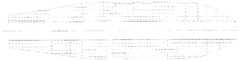
图1为现有技术中的球囊导管远端结构示意图,1 is a schematic view showing the distal structure of a balloon catheter in the prior art;
图2为图1中的A处放大图,Figure 2 is an enlarged view of A in Figure 1,
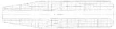
图3为本发明的实施例一的结构示意图,3 is a schematic structural view of
图4为图3中B处放大图,Figure 4 is an enlarged view of B in Figure 3,
图5为图3中C处放大图,Figure 5 is an enlarged view of the portion C in Figure 3,
图6为图3中D处放大图,Figure 6 is an enlarged view of the portion D in Figure 3,
图7为图3中E处放大图,Figure 7 is an enlarged view of E in Figure 3,
图8为本发明的实施例二的远端结构示意图,8 is a schematic structural view of a distal end according to
图9为本发明的实施例三的远端结构示意图,9 is a schematic structural view of a distal end according to
图10为本发明的实施例四的远端结构示意图,10 is a schematic structural view of a distal end according to
图11为本发明的实施例五的远端结构示意图,11 is a schematic structural view of a distal end according to
图12为本发明的实施例六的远端结构示意图,12 is a schematic structural view of a distal end according to
图13为本发明的实施例七的远端结构示意图,13 is a schematic structural view of a distal end according to
图14为本发明的实施例八的远端结构示意图,14 is a schematic structural view of a distal end according to
图15为本发明的实施例九的远端结构示意图,15 is a schematic structural view of a distal end of Embodiment 9 of the present invention,
图16为本发明为通过导丝(OTW)型球囊导管时的示意图,Figure 16 is a schematic view of the present invention when passing through a guide wire (OTW) type balloon catheter,
图17为头端设有凸起部时的一种结构示意图,Figure 17 is a schematic view showing a structure when the head end is provided with a convex portion.
图18为头端设有凸起部时的另一种结构示意图,Figure 18 is a schematic view showing another structure when the head end is provided with a convex portion.
图19为头端设有凸起部时的又一种结构示意图,Figure 19 is a schematic view showing another structure when the head end is provided with a convex portion.
图20为头端设有凸起部时的轴向视图,Figure 20 is an axial view of the head end with a raised portion,
图21为头端设有非对称凸起部时的一种结构示意图,Figure 21 is a schematic view showing a structure when the head end is provided with an asymmetric convex portion.
图22为头端设有非对称凸起部时的另一种结构示意图,Figure 22 is a schematic view showing another structure when the head end is provided with an asymmetric convex portion.
图23为头端设有非对称凸起部时的轴向视图,Figure 23 is an axial view of the head end with an asymmetric projection.
图24为头端只设有部分凸起部时的一种结构示意图,Figure 24 is a schematic view showing a structure when only a part of the boss is provided at the head end.
图25为头端只设有部分凸起部时的另一种结构示意图,Figure 25 is a schematic view showing another structure when only a part of the boss is provided at the head end.
图26为头端凸起部的轴向截面边缘呈多边形时的示意图,Figure 26 is a schematic view showing a state in which the axial section of the head end projection is polygonal.
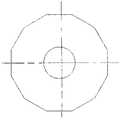
图27为头端凸起部的径向截面呈多边形时的示意图,Figure 27 is a schematic view showing a radial section of the head end boss being polygonal.
图28为头端壁厚加厚时的一种结构示意图,Figure 28 is a schematic view showing the structure of the head end wall thickened.
图29为头端壁厚加厚时的另一种结构示意图,Figure 29 is a schematic view showing another structure when the wall thickness of the head end is thickened.
图30为头端壁厚加厚时的轴向视图,Figure 30 is an axial view of the head end wall thickened,
图31为头端壁厚加厚时的又一种结构示意图,Figure 31 is a schematic view showing another structure when the thickness of the head end is thickened.
图32为图31中的头端轴向视图,Figure 32 is an axial end view of the head end of Figure 31,
图33为头端壁厚加厚同时后侧设有锥面的一种结构示意图,Figure 33 is a schematic view showing a structure in which the thickness of the head end is thickened and the back side is provided with a tapered surface.
图34为头端壁厚加厚同时后侧设有锥面的又一种结构示意图,Figure 34 is a schematic view showing another structure in which the thickness of the head end is thickened and the back side is provided with a tapered surface.
图35为头端壁厚加厚同时后侧设有锥面的另一种结构示意图,Figure 35 is a schematic view showing another structure in which the thickness of the head end is thickened and the back side is provided with a tapered surface.
图36为头端壁厚加厚时轴向截面边缘呈多边形时的示意图,Figure 36 is a schematic view showing the edge of the axial section being polygonal when the thickness of the head end is thick.
图37为头端壁厚加厚时径向截面呈多边形时的示意图。Fig. 37 is a schematic view showing a case where the radial thickness of the head end is thick and the cross section is polygonal.
其中,1为内管,11为头端,111为连接杆,12为导丝出口,13为显影环,2为外管,3为球囊,31为通液腔,32为连接管,4为柔性连接部,41为过渡斜面,5为接头,6为导管,7为应变释放管,8为平端面。Wherein, 1 is the inner tube, 11 is the head end, 111 is the connecting rod, 12 is the guide wire outlet, 13 is the developing ring, 2 is the outer tube, 3 is the balloon, 31 is the liquid passing chamber, 32 is the connecting tube, 4 For the flexible joint, 41 is the transition bevel, 5 is the joint, 6 is the conduit, 7 is the strain relief tube, and 8 is the flat end face.
下面结合附图对本发明作进一步详述。The invention will be further described in detail below with reference to the accompanying drawings.
如图3~7所示,本发明包括内管1、外管2、球囊3、接头5、导管6和应变释放管7,其中内管1设置于外管2中,内管1内部贯通以供导丝穿过,如图3、图5和图7所示,球囊3套设于内管1的远端(所述远端即远离操作人员的一端,也即自由端),且所述球囊3的一端与所述外管2相连,另一端与所述内管1相连,所述球囊3内为通液腔31,如图3~4所示,设置于所述球囊3内的一段内管1外侧设有多个显影环13,通过相应的仪器能够显示显影环13的位置,从而帮助操作人员了解球囊的位置,如图6所示,在外管2的近端(所述近端即靠近操作人员的一端)内设有导管6,且所述导管6设置于内管1外侧,如图3所示,所述导管6的近端与接头5相连,在所述接头5上设有应变释放管7,且所述应变释放管7扣装于所述接头5的远端,所述应变释放管7用于避免应力集中,以提高球囊导管的使用寿命。As shown in Figures 3 to 7, the present invention comprises an
所述球囊3采用加压加热吹塑成型,将内径为0.3~1.5mm、外径为0.6~2.0mm、长度为400~600mm的尼龙管材,在压力为300~600PSI、160~220摄氏度的条件下吹制,得到直径为2.0~5.0mm、长为5.0~30.0mm的圆筒即为球囊3主体,如图5和图7所示,在所述球囊3两端分别设置有连接管32,所述连接管32的外径为0.60~1.02mm,长度为1.0~10.0mm,球囊3通过两端的连接管32分别套装于所述内管1和外管2上,从而实现与内管1和外管2相连,球囊3与内管1之间形成通液腔31,所述通液腔31在通入显影液之后能够胀大,从而将支架撑开。The
所述外管2采用尼龙、聚乙烯、聚丙烯或嵌段聚酰胺材质,在挤出温度200~280摄氏度,冷却温度15~40摄氏度的条件下挤出长为250~1600mm、外径为0.76~0.86mm、厚度为0.04~0.14mm的管材即得到所述外管2。The
所述内管1采用尼龙、聚乙烯、聚丙烯或嵌段聚酰胺材质,与外管2在相同的条件下制得,长度为250~1600mm,外径为0.50~0.61mm。The
如图7所示,所述内管1的远端伸出球囊3后通过柔性连接部4与头端11相连,当球囊导管进入弯曲血管时,所述柔性连接部4在外力作用下会顺应血管弯形弯曲,从而有效避免头端11顶住支架梁,保证导管通过,所述柔性连接部4采用尼龙、聚乙烯、聚丙烯或嵌段聚酰胺材质制成。As shown in FIG. 7, the distal end of the
所述柔性连接部4与头端11可设计成分体结构,也可以设计成一体结构。当柔性连接部4与头端11为分体结构时,所述柔性连接部4可采用尼龙、聚乙烯、聚丙烯、嵌段聚酰胺或聚氨酯材质并通过挤出方式成型,在挤出温度200~280摄氏度,冷却温度15~40摄氏度的条件下挤出管材,长0~20mm,外径为0.50~2mm,厚度为0.07~0.82mm。当柔性连接部4与头端11为一体结构时,所述柔性连接部4和头端11采用尼龙、聚乙烯、聚丙烯、嵌段聚酰胺或聚氨酯材质,并利用注塑的方法在相应形状的模具内注塑一体成型。The flexible connecting
所述头端11根据需要可设计成锥状,另外如图1~2所示,如果将后扩张球囊导管也设计成锥状,由于头端11前端会有一个较小的平端面8,在球囊导管沿着导丝送入支架时,所述平端面8往往会顶住支架梁而使导管无法通过,为了解决这个问题,所述头端11结构需作出改进。The
实施例1Example 1
如图3所示,本实施例为快速交换型球囊导管,在导管中部设有导丝出口12。As shown in Fig. 3, this embodiment is a quick exchange type balloon catheter, and a
如图7所示,本实施例中采用呈锥状的头端11,且所述头端11与柔性连接部4为分体结构。所述柔性连接部4一端套装在内管1上,所述柔性连接部4的另一端通过止口配合与所述头端11的后侧连接,所述柔性连接部4的直径与球囊3的连接管32直径相同,同时所述柔性连接部4的直径与所述头端11外锥面的最大直径也相同。当球囊导管进入弯曲血管时,所述柔性连接部4在外力作用下易产生顺应血管弯形的弯曲,从而保证导管通过。As shown in FIG. 7, in the present embodiment, a tapered
实施例2Example 2
如图8所示,本实施例与实施例1不同之处在于所述头端11与柔性连接部4为一体成型结构,当球囊导管进入弯曲血管时,所述柔性连接部4以及头端11在外力作用下均易产生顺应血管弯形的弯曲,从而保证导管通过。As shown in FIG. 8, the present embodiment is different from the first embodiment in that the
实施例3Example 3
如图9所示,本实施例与实施例1不同之处在于所述头端11外锥面的最大外径小于所述柔性连接部4的直径,并且在所述柔性连接部4与头端11相连的一端设有过渡斜面41,所述柔性连接部4的直径与球囊3的连接管32直径相同。As shown in FIG. 9, the present embodiment is different from
实施例4Example 4
如图10所示,本实施例与实施例1不同之处在于所述头端11外锥面的最大直径大于所述柔性连接部4的直径,所述柔性连接部4的直径与球囊3的连接管32直径相同。As shown in FIG. 10, the present embodiment is different from
实施例5Example 5
如图3所示,本实施例为快速交换型球囊导管,在导管中部设有导丝出口12。As shown in Fig. 3, this embodiment is a quick exchange type balloon catheter, and a
如图11所示,本实施例采用设有凸起部的头端11,且所述头端11与柔性连接部4为分体结构。所述头端11包括前侧的凸起部和后侧的连接杆111,所述柔性连接部4一端套装在内管1上,另一端通过止口配合与所述头端11后侧的连接杆111相连,所述柔性连接部4的直径、所述球囊3的连接管32直径以及所述头端11的连接杆111直径均相同,所述头端11前侧的凸起部最大外径大于所述柔性连接部4的直径以及头端11其他部分的直径,并且所述头端11的凸起部的最大高度大于支架与血管内壁的距离,以使导管顺利滑过支架梁。As shown in FIG. 11, the present embodiment employs a
如图11所示,所述凸起部设置于头端11前侧,且所述头端11前侧的内侧孔壁和外侧壁之间通过所述凸起部衔接过渡,所述凸起部外表面可以设置为光滑面,这样便不存在抵住支架梁的平端面8,从而使导管顺利滑过支架梁,或者如图26所示,所述凸起部外表面包括多个平面,任意相邻两个平面之间的夹角均为钝角,这样便形成近似弧面的形状,并且凸起部外表面与头端11内侧孔壁相连的平面向头端11后侧倾斜,这样便不存在能够抵住支架梁的平端面8,也可以起到顺利滑过支架梁的作用,加上所述柔性连接部4在外力作用下易产生顺应血管弯形的弯曲,从而进一步保证导管顺利通过。如图19所示,由于导丝由头端11内孔穿过,所述头端11的出口内侧也可以设置成向外侧翻转并与头端11外侧的凸起部光滑衔接的弧面,从而使头端11出口与导丝接触时更加平滑。所述凸起部外表面也可以设置成光滑面与平面衔接的结构,只要前侧与头端11的内孔壁相连的面不形成能够抵住支架梁的平端面8即可。As shown in FIG. 11 , the protrusion is disposed on the front side of the
如图17~20所示,所述头端11上的凸起部可以为对称结构绕所述头端11轴线旋转而成的旋转体,也即所述凸起部的任一轴向截面均为对称结构,只不过所述凸起部轴向截面的外边缘根据需要设置成不同弧度,或者所述头端11上的凸起部也可以设计成非对称形式,比如图21~23所示,所述头端11两侧分别设有外表面弧度不同的凸起部,或者如图24~25所示,所述头端11前侧外表面上只有一部分设置凸起部,其余部分为锥度指向头端11前侧的锥面,或者是向头端11内侧倾斜的斜面,所述头端11和柔性连接部4径向截面可以设计成圆形,或者如图27所示,沿着所述头端11的轴向看去,所述头端11和柔性连接部4径向截面也可以设计成呈近似圆形的多边形。As shown in FIGS. 17 to 20, the convex portion on the
实施例6Example 6
如图12所示,本实施例与实施例5的不同之处在于:所述头端11省去了呈管状的连接杆111,头端11的凸起部直接与所述柔性连接部4相连。As shown in FIG. 12, this embodiment is different from
实施例7Example 7
如图13所示,本实施例与实施例5的不同之处在于:所述头端11与柔性连接部4为一体结构,当球囊导管进入弯曲血管时,所述柔性连接部4以及头端11在外力作用下均易产生顺应血管弯形的弯曲,从而保证导管通过。As shown in FIG. 13, the present embodiment is different from the
实施例8Example 8
如图3所示,本实施例为快速交换型的球囊导管,在导管中部设有导丝出口12。As shown in Fig. 3, this embodiment is a quick-exchange type balloon catheter, and a
如图14所示,本实施例中采用壁厚加厚的头端11,且所述头端11与柔性连接部4为分体结构。所述柔性连接部4一端套装在内管1上,另一端通过止口配合与所述头端11后侧相连,所述柔性连接部4的直径与所述头端11的直径相同,并且均大于所述球囊3的连接管32直径,并且所述头端11的壁厚大于支架与血管内壁的距离,以使导管顺利滑过支架梁。As shown in FIG. 14, in the present embodiment, the
在所述头端11前侧设有一个逐渐收窄的过渡面,所述头端11前侧的内侧孔壁与外侧壁之间通过所述过渡面衔接,如图14所示,所述过渡面可以为直接与头端11的内孔壁相连的光滑面,这样便不存在会抵住支架梁的平端面8,导管可以顺利滑过支架梁,或者如图36所示,所述过渡面包括多个平面,任意相邻两平面之间的夹角为钝角,这样便形成近似弧面的形状,并且与头端11内侧孔壁相连的平面向头端11后侧倾斜,这样便不存在能够抵住支架梁的平端面8,也可以起到顺利滑过支架梁的作用,加上所述柔性连接部4在外力作用下易产生顺应血管弯形的弯曲,从而进一步保证导管顺利通过。所述过渡面也可以设置成光滑面与平面衔接的结构,只要前侧与头端11的内孔壁相连的面不形成能够抵住支架梁的平端面8即可。a tapered surface is formed on the front side of the
如图14及图28所示,所述头端11前侧的光滑面设置于头端11外侧且可以根据实际需要设置成弧度不同的光滑面。如图29所示,由于导丝由头端11内孔穿过,所述头端11的出口内侧也可以设置成向外侧翻转并与头端11外侧的过渡面光滑衔接的弧面,从而使头端11出口与导丝接触时更加平滑。如图30所示,所述头端11可以为对称结构绕所述头端11轴线旋转而成的旋转体,即沿着所述头端11的轴向看去,所述头端11的径向截面呈圆形,或者如图37所示,沿着所述头端11的轴向看去,所述头端11和柔性连接部4径向截面也可以设计成呈近似圆形的多边形。如图31~32所示,所述头端11前侧外表面只有一部分设置成过渡面,其余部分设置成锥面或斜面,如图33~35所示,所述头端11的后侧可进一步设计成锥度指向头端11后侧的锥状或斜面。As shown in FIG. 14 and FIG. 28, the smooth surface on the front side of the
实施例9Example 9
如图16所示,本实施例为通过导丝(OTW)型球囊导管,导丝接口12设置于接头5上。As shown in Fig. 16, in the present embodiment, the
如图15所示,本实施例中的头端11与柔性连接部4为分体结构,且所述柔性连接部4的初始形状呈弯曲状,所述柔性连接部4一端套装在内管1上,另一端通过止口配合与所述头端11相连,当球囊导管进入弯曲血管时,所述柔性连接部4在外力作用下会进一步顺应血管弯形的弯曲,从而保证导管通过。As shown in FIG. 15 , the
所述柔性连接部4可以呈光滑弧状弯曲,也可以呈角状折弯。The flexible connecting
所述柔性连接部4与头端11可设计成分体结构,也可以设计成一体结构,所述头端11也可采用其他实施例中的结构。The flexible connecting
Claims (10)
Translated fromChinesePriority Applications (1)
| Application Number | Priority Date | Filing Date | Title |
|---|---|---|---|
| JP2017600108UJP3217806U (en) | 2016-05-25 | 2017-01-17 | Balloon catheter with flexible connection between tip and balloon |
Applications Claiming Priority (2)
| Application Number | Priority Date | Filing Date | Title |
|---|---|---|---|
| CN201610352255.3ACN107432980A (en) | 2016-05-25 | 2016-05-25 | The foley's tube of flexible joint is provided between a kind of head end and sacculus |
| CN201610352255.3 | 2016-05-25 |
Publications (1)
| Publication Number | Publication Date |
|---|---|
| WO2017202042A1true WO2017202042A1 (en) | 2017-11-30 |
Family
ID=60411006
Family Applications (1)
| Application Number | Title | Priority Date | Filing Date |
|---|---|---|---|
| PCT/CN2017/071342CeasedWO2017202042A1 (en) | 2016-05-25 | 2017-01-17 | Balloon catheter provided with flexible connecting part between tip and balloon |
Country Status (3)
| Country | Link |
|---|---|
| JP (1) | JP3217806U (en) |
| CN (1) | CN107432980A (en) |
| WO (1) | WO2017202042A1 (en) |
Cited By (20)
| Publication number | Priority date | Publication date | Assignee | Title |
|---|---|---|---|---|
| US10595994B1 (en) | 2018-09-20 | 2020-03-24 | Vdyne, Llc | Side-delivered transcatheter heart valve replacement |
| US11071627B2 (en) | 2018-10-18 | 2021-07-27 | Vdyne, Inc. | Orthogonally delivered transcatheter heart valve frame for valve in valve prosthesis |
| US11076956B2 (en) | 2019-03-14 | 2021-08-03 | Vdyne, Inc. | Proximal, distal, and anterior anchoring tabs for side-delivered transcatheter mitral valve prosthesis |
| US11109969B2 (en) | 2018-10-22 | 2021-09-07 | Vdyne, Inc. | Guidewire delivery of transcatheter heart valve |
| US11166814B2 (en) | 2019-08-20 | 2021-11-09 | Vdyne, Inc. | Delivery and retrieval devices and methods for side-deliverable transcatheter prosthetic valves |
| US11173027B2 (en) | 2019-03-14 | 2021-11-16 | Vdyne, Inc. | Side-deliverable transcatheter prosthetic valves and methods for delivering and anchoring the same |
| US11185409B2 (en) | 2019-01-26 | 2021-11-30 | Vdyne, Inc. | Collapsible inner flow control component for side-delivered transcatheter heart valve prosthesis |
| US11202706B2 (en) | 2019-05-04 | 2021-12-21 | Vdyne, Inc. | Cinch device and method for deployment of a side-delivered prosthetic heart valve in a native annulus |
| US11234813B2 (en) | 2020-01-17 | 2022-02-01 | Vdyne, Inc. | Ventricular stability elements for side-deliverable prosthetic heart valves and methods of delivery |
| US11253359B2 (en) | 2018-12-20 | 2022-02-22 | Vdyne, Inc. | Proximal tab for side-delivered transcatheter heart valves and methods of delivery |
| US11273032B2 (en) | 2019-01-26 | 2022-03-15 | Vdyne, Inc. | Collapsible inner flow control component for side-deliverable transcatheter heart valve prosthesis |
| US11273033B2 (en) | 2018-09-20 | 2022-03-15 | Vdyne, Inc. | Side-delivered transcatheter heart valve replacement |
| US11278437B2 (en) | 2018-12-08 | 2022-03-22 | Vdyne, Inc. | Compression capable annular frames for side delivery of transcatheter heart valve replacement |
| US11298227B2 (en) | 2019-03-05 | 2022-04-12 | Vdyne, Inc. | Tricuspid regurgitation control devices for orthogonal transcatheter heart valve prosthesis |
| US11331186B2 (en) | 2019-08-26 | 2022-05-17 | Vdyne, Inc. | Side-deliverable transcatheter prosthetic valves and methods for delivering and anchoring the same |
| US11344413B2 (en) | 2018-09-20 | 2022-05-31 | Vdyne, Inc. | Transcatheter deliverable prosthetic heart valves and methods of delivery |
| CN115920211A (en)* | 2022-12-12 | 2023-04-07 | 浙江巴泰医疗科技有限公司 | A tip structure, a balloon dilatation catheter comprising the tip structure, and a preparation method thereof |
| US11786366B2 (en) | 2018-04-04 | 2023-10-17 | Vdyne, Inc. | Devices and methods for anchoring transcatheter heart valve |
| US12186187B2 (en) | 2018-09-20 | 2025-01-07 | Vdyne, Inc. | Transcatheter deliverable prosthetic heart valves and methods of delivery |
| US12343256B2 (en) | 2019-01-10 | 2025-07-01 | Vdyne, Inc. | Anchor hook for side-delivery transcatheter heart valve prosthesis |
Families Citing this family (3)
| Publication number | Priority date | Publication date | Assignee | Title |
|---|---|---|---|---|
| CN109908453B (en)* | 2019-03-15 | 2022-05-31 | 兰州大学第一医院 | A device for assisting guide catheter through tortuous blood vessels |
| CN110721392A (en)* | 2019-09-29 | 2020-01-24 | 深圳泰睿仕医疗科技有限公司 | Disposable ureter guide sheath |
| CN113081166A (en)* | 2021-04-29 | 2021-07-09 | 苏州中天医疗器械科技有限公司 | Micro-catheter |
Citations (6)
| Publication number | Priority date | Publication date | Assignee | Title |
|---|---|---|---|---|
| WO2013146306A1 (en)* | 2012-03-28 | 2013-10-03 | テルモ・クリニカルサプライ株式会社 | Balloon catheter for closing blood vessel |
| CN104524685A (en)* | 2015-02-03 | 2015-04-22 | 孙英贤 | Balloon catheter |
| CN204543239U (en)* | 2014-12-30 | 2015-08-12 | 先健科技(深圳)有限公司 | Foley's tube |
| CN205867280U (en)* | 2016-05-25 | 2017-01-11 | 孙英贤 | Be equipped with sacculus pipe of flexonics portion between head end and sacculus |
| CN205964676U (en)* | 2016-05-25 | 2017-02-22 | 孙英贤 | Adopt sacculus pipe of curved form head end |
| CN206007781U (en)* | 2016-05-25 | 2017-03-15 | 孙英贤 | A kind of foley's tube using non-taper head end |
Family Cites Families (5)
| Publication number | Priority date | Publication date | Assignee | Title |
|---|---|---|---|---|
| US7169162B2 (en)* | 2002-07-03 | 2007-01-30 | Orbusneich Medical, Inc. | Balloon catheter |
| US8403885B2 (en)* | 2007-12-17 | 2013-03-26 | Abbott Cardiovascular Systems Inc. | Catheter having transitioning shaft segments |
| CN102488955B (en)* | 2011-12-07 | 2013-06-05 | 湖南埃普特医疗器械有限公司 | Balloon guide catheter, and preparation method thereof |
| CN203060560U (en)* | 2013-01-25 | 2013-07-17 | 湖南埃普特医疗器械有限公司 | Balloon catheter of PTCA (Percutaneous Transluminal Coronary Angioplasty) |
| CN203370191U (en)* | 2013-06-26 | 2014-01-01 | 上海英诺伟医疗器械有限公司 | Novel balloon dilatation catheter |
- 2016
- 2016-05-25CNCN201610352255.3Apatent/CN107432980A/enactivePending
- 2017
- 2017-01-17JPJP2017600108Upatent/JP3217806U/enactiveActive
- 2017-01-17WOPCT/CN2017/071342patent/WO2017202042A1/ennot_activeCeased
Patent Citations (6)
| Publication number | Priority date | Publication date | Assignee | Title |
|---|---|---|---|---|
| WO2013146306A1 (en)* | 2012-03-28 | 2013-10-03 | テルモ・クリニカルサプライ株式会社 | Balloon catheter for closing blood vessel |
| CN204543239U (en)* | 2014-12-30 | 2015-08-12 | 先健科技(深圳)有限公司 | Foley's tube |
| CN104524685A (en)* | 2015-02-03 | 2015-04-22 | 孙英贤 | Balloon catheter |
| CN205867280U (en)* | 2016-05-25 | 2017-01-11 | 孙英贤 | Be equipped with sacculus pipe of flexonics portion between head end and sacculus |
| CN205964676U (en)* | 2016-05-25 | 2017-02-22 | 孙英贤 | Adopt sacculus pipe of curved form head end |
| CN206007781U (en)* | 2016-05-25 | 2017-03-15 | 孙英贤 | A kind of foley's tube using non-taper head end |
Cited By (21)
| Publication number | Priority date | Publication date | Assignee | Title |
|---|---|---|---|---|
| US11786366B2 (en) | 2018-04-04 | 2023-10-17 | Vdyne, Inc. | Devices and methods for anchoring transcatheter heart valve |
| US11273033B2 (en) | 2018-09-20 | 2022-03-15 | Vdyne, Inc. | Side-delivered transcatheter heart valve replacement |
| US11344413B2 (en) | 2018-09-20 | 2022-05-31 | Vdyne, Inc. | Transcatheter deliverable prosthetic heart valves and methods of delivery |
| US12186187B2 (en) | 2018-09-20 | 2025-01-07 | Vdyne, Inc. | Transcatheter deliverable prosthetic heart valves and methods of delivery |
| US10595994B1 (en) | 2018-09-20 | 2020-03-24 | Vdyne, Llc | Side-delivered transcatheter heart valve replacement |
| US11071627B2 (en) | 2018-10-18 | 2021-07-27 | Vdyne, Inc. | Orthogonally delivered transcatheter heart valve frame for valve in valve prosthesis |
| US11109969B2 (en) | 2018-10-22 | 2021-09-07 | Vdyne, Inc. | Guidewire delivery of transcatheter heart valve |
| US11278437B2 (en) | 2018-12-08 | 2022-03-22 | Vdyne, Inc. | Compression capable annular frames for side delivery of transcatheter heart valve replacement |
| US11253359B2 (en) | 2018-12-20 | 2022-02-22 | Vdyne, Inc. | Proximal tab for side-delivered transcatheter heart valves and methods of delivery |
| US12343256B2 (en) | 2019-01-10 | 2025-07-01 | Vdyne, Inc. | Anchor hook for side-delivery transcatheter heart valve prosthesis |
| US11185409B2 (en) | 2019-01-26 | 2021-11-30 | Vdyne, Inc. | Collapsible inner flow control component for side-delivered transcatheter heart valve prosthesis |
| US11273032B2 (en) | 2019-01-26 | 2022-03-15 | Vdyne, Inc. | Collapsible inner flow control component for side-deliverable transcatheter heart valve prosthesis |
| US11298227B2 (en) | 2019-03-05 | 2022-04-12 | Vdyne, Inc. | Tricuspid regurgitation control devices for orthogonal transcatheter heart valve prosthesis |
| US11173027B2 (en) | 2019-03-14 | 2021-11-16 | Vdyne, Inc. | Side-deliverable transcatheter prosthetic valves and methods for delivering and anchoring the same |
| US11076956B2 (en) | 2019-03-14 | 2021-08-03 | Vdyne, Inc. | Proximal, distal, and anterior anchoring tabs for side-delivered transcatheter mitral valve prosthesis |
| US11202706B2 (en) | 2019-05-04 | 2021-12-21 | Vdyne, Inc. | Cinch device and method for deployment of a side-delivered prosthetic heart valve in a native annulus |
| US11179239B2 (en) | 2019-08-20 | 2021-11-23 | Vdyne, Inc. | Delivery and retrieval devices and methods for side-deliverable transcatheter prosthetic valves |
| US11166814B2 (en) | 2019-08-20 | 2021-11-09 | Vdyne, Inc. | Delivery and retrieval devices and methods for side-deliverable transcatheter prosthetic valves |
| US11331186B2 (en) | 2019-08-26 | 2022-05-17 | Vdyne, Inc. | Side-deliverable transcatheter prosthetic valves and methods for delivering and anchoring the same |
| US11234813B2 (en) | 2020-01-17 | 2022-02-01 | Vdyne, Inc. | Ventricular stability elements for side-deliverable prosthetic heart valves and methods of delivery |
| CN115920211A (en)* | 2022-12-12 | 2023-04-07 | 浙江巴泰医疗科技有限公司 | A tip structure, a balloon dilatation catheter comprising the tip structure, and a preparation method thereof |
Also Published As
| Publication number | Publication date |
|---|---|
| CN107432980A (en) | 2017-12-05 |
| JP3217806U (en) | 2018-09-06 |
Similar Documents
| Publication | Publication Date | Title |
|---|---|---|
| WO2017202042A1 (en) | Balloon catheter provided with flexible connecting part between tip and balloon | |
| CN109567991B (en) | delivery sheath | |
| JP6831335B2 (en) | Balloon catheters and long medical bodies | |
| CN205494628U (en) | balloon catheter | |
| KR102491375B1 (en) | BALLOON CATHETER | |
| CN116782844A (en) | balloon catheter | |
| CN114470488B (en) | Balloon catheter | |
| US20220088354A1 (en) | Balloon catheter | |
| CN205964676U (en) | Adopt sacculus pipe of curved form head end | |
| CN209984773U (en) | A guide wire and balloon catheter assembly | |
| CN104524685B (en) | A kind of foley's tube | |
| WO2020255923A1 (en) | Balloon catheter | |
| WO2018019165A1 (en) | Stent delivery system | |
| CN108245769A (en) | Foley's tube | |
| CN206214242U (en) | Stent delivery system | |
| CN218356933U (en) | Variable-diameter intracranial balloon dilatation catheter | |
| CN205867280U (en) | Be equipped with sacculus pipe of flexonics portion between head end and sacculus | |
| CN100522074C (en) | Fast-exchanging and transferring system | |
| CN116744998A (en) | balloon catheter | |
| CN108273176B (en) | Balloon catheter | |
| CN204446956U (en) | A kind of foley's tube | |
| WO2017202073A1 (en) | Balloon catheter employing non-tapered tip | |
| CN206214554U (en) | Foley's tube with the asymmetric sacculus in two ends | |
| CN217119105U (en) | Bifurcated sacculus | |
| WO2018019164A1 (en) | Balloon catheter with balloon with two asymmetrical ends |
Legal Events
| Date | Code | Title | Description |
|---|---|---|---|
| ENP | Entry into the national phase | Ref document number:2017600108 Country of ref document:JP Kind code of ref document:A | |
| NENP | Non-entry into the national phase | Ref country code:DE | |
| 121 | Ep: the epo has been informed by wipo that ep was designated in this application | Ref document number:17801899 Country of ref document:EP Kind code of ref document:A1 | |
| 122 | Ep: pct application non-entry in european phase | Ref document number:17801899 Country of ref document:EP Kind code of ref document:A1 |