WO2017199557A1 - Imaging device, imaging method, program and non-transitory recording medium - Google Patents
Imaging device, imaging method, program and non-transitory recording mediumDownload PDFInfo
- Publication number
- WO2017199557A1 WO2017199557A1PCT/JP2017/009862JP2017009862WWO2017199557A1WO 2017199557 A1WO2017199557 A1WO 2017199557A1JP 2017009862 WJP2017009862 WJP 2017009862WWO 2017199557 A1WO2017199557 A1WO 2017199557A1
- Authority
- WO
- WIPO (PCT)
- Prior art keywords
- image
- light
- optical system
- light receiving
- sensor
- Prior art date
- Legal status (The legal status is an assumption and is not a legal conclusion. Google has not performed a legal analysis and makes no representation as to the accuracy of the status listed.)
- Ceased
Links
Images


Classifications
- G—PHYSICS
- G02—OPTICS
- G02B—OPTICAL ELEMENTS, SYSTEMS OR APPARATUS
- G02B13/00—Optical objectives specially designed for the purposes specified below
- G02B13/04—Reversed telephoto objectives
- G—PHYSICS
- G02—OPTICS
- G02B—OPTICAL ELEMENTS, SYSTEMS OR APPARATUS
- G02B13/00—Optical objectives specially designed for the purposes specified below
- G02B13/02—Telephoto objectives, i.e. systems of the type + - in which the distance from the front vertex to the image plane is less than the equivalent focal length
- G—PHYSICS
- G02—OPTICS
- G02B—OPTICAL ELEMENTS, SYSTEMS OR APPARATUS
- G02B17/00—Systems with reflecting surfaces, with or without refracting elements
- G02B17/08—Catadioptric systems
- G—PHYSICS
- G02—OPTICS
- G02B—OPTICAL ELEMENTS, SYSTEMS OR APPARATUS
- G02B17/00—Systems with reflecting surfaces, with or without refracting elements
- G02B17/08—Catadioptric systems
- G02B17/0804—Catadioptric systems using two curved mirrors
- G02B17/0808—Catadioptric systems using two curved mirrors on-axis systems with at least one of the mirrors having a central aperture
- G—PHYSICS
- G02—OPTICS
- G02B—OPTICAL ELEMENTS, SYSTEMS OR APPARATUS
- G02B17/00—Systems with reflecting surfaces, with or without refracting elements
- G02B17/08—Catadioptric systems
- G02B17/0896—Catadioptric systems with variable magnification or multiple imaging planes, including multispectral systems
- G—PHYSICS
- G02—OPTICS
- G02F—OPTICAL DEVICES OR ARRANGEMENTS FOR THE CONTROL OF LIGHT BY MODIFICATION OF THE OPTICAL PROPERTIES OF THE MEDIA OF THE ELEMENTS INVOLVED THEREIN; NON-LINEAR OPTICS; FREQUENCY-CHANGING OF LIGHT; OPTICAL LOGIC ELEMENTS; OPTICAL ANALOGUE/DIGITAL CONVERTERS
- G02F1/00—Devices or arrangements for the control of the intensity, colour, phase, polarisation or direction of light arriving from an independent light source, e.g. switching, gating or modulating; Non-linear optics
- G02F1/01—Devices or arrangements for the control of the intensity, colour, phase, polarisation or direction of light arriving from an independent light source, e.g. switching, gating or modulating; Non-linear optics for the control of the intensity, phase, polarisation or colour
- G02F1/13—Devices or arrangements for the control of the intensity, colour, phase, polarisation or direction of light arriving from an independent light source, e.g. switching, gating or modulating; Non-linear optics for the control of the intensity, phase, polarisation or colour based on liquid crystals, e.g. single liquid crystal display cells
- G02F1/137—Devices or arrangements for the control of the intensity, colour, phase, polarisation or direction of light arriving from an independent light source, e.g. switching, gating or modulating; Non-linear optics for the control of the intensity, phase, polarisation or colour based on liquid crystals, e.g. single liquid crystal display cells characterised by the electro-optical or magneto-optical effect, e.g. field-induced phase transition, orientation effect, guest-host interaction or dynamic scattering
- G—PHYSICS
- G03—PHOTOGRAPHY; CINEMATOGRAPHY; ANALOGOUS TECHNIQUES USING WAVES OTHER THAN OPTICAL WAVES; ELECTROGRAPHY; HOLOGRAPHY
- G03B—APPARATUS OR ARRANGEMENTS FOR TAKING PHOTOGRAPHS OR FOR PROJECTING OR VIEWING THEM; APPARATUS OR ARRANGEMENTS EMPLOYING ANALOGOUS TECHNIQUES USING WAVES OTHER THAN OPTICAL WAVES; ACCESSORIES THEREFOR
- G03B5/00—Adjustment of optical system relative to image or object surface other than for focusing
- G—PHYSICS
- G03—PHOTOGRAPHY; CINEMATOGRAPHY; ANALOGOUS TECHNIQUES USING WAVES OTHER THAN OPTICAL WAVES; ELECTROGRAPHY; HOLOGRAPHY
- G03B—APPARATUS OR ARRANGEMENTS FOR TAKING PHOTOGRAPHS OR FOR PROJECTING OR VIEWING THEM; APPARATUS OR ARRANGEMENTS EMPLOYING ANALOGOUS TECHNIQUES USING WAVES OTHER THAN OPTICAL WAVES; ACCESSORIES THEREFOR
- G03B7/00—Control of exposure by setting shutters, diaphragms or filters, separately or conjointly
- G03B7/28—Circuitry to measure or to take account of the object contrast
- G—PHYSICS
- G03—PHOTOGRAPHY; CINEMATOGRAPHY; ANALOGOUS TECHNIQUES USING WAVES OTHER THAN OPTICAL WAVES; ELECTROGRAPHY; HOLOGRAPHY
- G03B—APPARATUS OR ARRANGEMENTS FOR TAKING PHOTOGRAPHS OR FOR PROJECTING OR VIEWING THEM; APPARATUS OR ARRANGEMENTS EMPLOYING ANALOGOUS TECHNIQUES USING WAVES OTHER THAN OPTICAL WAVES; ACCESSORIES THEREFOR
- G03B9/00—Exposure-making shutters; Diaphragms
- H—ELECTRICITY
- H04—ELECTRIC COMMUNICATION TECHNIQUE
- H04N—PICTORIAL COMMUNICATION, e.g. TELEVISION
- H04N23/00—Cameras or camera modules comprising electronic image sensors; Control thereof
- H04N23/50—Constructional details
- H04N23/55—Optical parts specially adapted for electronic image sensors; Mounting thereof
- H—ELECTRICITY
- H04—ELECTRIC COMMUNICATION TECHNIQUE
- H04N—PICTORIAL COMMUNICATION, e.g. TELEVISION
- H04N23/00—Cameras or camera modules comprising electronic image sensors; Control thereof
- H04N23/60—Control of cameras or camera modules
- H04N23/698—Control of cameras or camera modules for achieving an enlarged field of view, e.g. panoramic image capture
- H—ELECTRICITY
- H04—ELECTRIC COMMUNICATION TECHNIQUE
- H04N—PICTORIAL COMMUNICATION, e.g. TELEVISION
- H04N23/00—Cameras or camera modules comprising electronic image sensors; Control thereof
- H04N23/70—Circuitry for compensating brightness variation in the scene
- H04N23/73—Circuitry for compensating brightness variation in the scene by influencing the exposure time
- H—ELECTRICITY
- H04—ELECTRIC COMMUNICATION TECHNIQUE
- H04N—PICTORIAL COMMUNICATION, e.g. TELEVISION
- H04N23/00—Cameras or camera modules comprising electronic image sensors; Control thereof
- H04N23/70—Circuitry for compensating brightness variation in the scene
- H04N23/741—Circuitry for compensating brightness variation in the scene by increasing the dynamic range of the image compared to the dynamic range of the electronic image sensors
- H—ELECTRICITY
- H04—ELECTRIC COMMUNICATION TECHNIQUE
- H04N—PICTORIAL COMMUNICATION, e.g. TELEVISION
- H04N23/00—Cameras or camera modules comprising electronic image sensors; Control thereof
- H04N23/70—Circuitry for compensating brightness variation in the scene
- H04N23/75—Circuitry for compensating brightness variation in the scene by influencing optical camera components
- G—PHYSICS
- G02—OPTICS
- G02B—OPTICAL ELEMENTS, SYSTEMS OR APPARATUS
- G02B27/00—Optical systems or apparatus not provided for by any of the groups G02B1/00 - G02B26/00, G02B30/00
- G02B27/10—Beam splitting or combining systems
- G02B27/1066—Beam splitting or combining systems for enhancing image performance, like resolution, pixel numbers, dual magnifications or dynamic range, by tiling, slicing or overlapping fields of view
- G—PHYSICS
- G02—OPTICS
- G02F—OPTICAL DEVICES OR ARRANGEMENTS FOR THE CONTROL OF LIGHT BY MODIFICATION OF THE OPTICAL PROPERTIES OF THE MEDIA OF THE ELEMENTS INVOLVED THEREIN; NON-LINEAR OPTICS; FREQUENCY-CHANGING OF LIGHT; OPTICAL LOGIC ELEMENTS; OPTICAL ANALOGUE/DIGITAL CONVERTERS
- G02F1/00—Devices or arrangements for the control of the intensity, colour, phase, polarisation or direction of light arriving from an independent light source, e.g. switching, gating or modulating; Non-linear optics
- G02F1/01—Devices or arrangements for the control of the intensity, colour, phase, polarisation or direction of light arriving from an independent light source, e.g. switching, gating or modulating; Non-linear optics for the control of the intensity, phase, polarisation or colour
- G02F1/13—Devices or arrangements for the control of the intensity, colour, phase, polarisation or direction of light arriving from an independent light source, e.g. switching, gating or modulating; Non-linear optics for the control of the intensity, phase, polarisation or colour based on liquid crystals, e.g. single liquid crystal display cells
- G02F1/133—Constructional arrangements; Operation of liquid crystal cells; Circuit arrangements
- G02F1/13306—Circuit arrangements or driving methods for the control of single liquid crystal cells
- G—PHYSICS
- G03—PHOTOGRAPHY; CINEMATOGRAPHY; ANALOGOUS TECHNIQUES USING WAVES OTHER THAN OPTICAL WAVES; ELECTROGRAPHY; HOLOGRAPHY
- G03B—APPARATUS OR ARRANGEMENTS FOR TAKING PHOTOGRAPHS OR FOR PROJECTING OR VIEWING THEM; APPARATUS OR ARRANGEMENTS EMPLOYING ANALOGOUS TECHNIQUES USING WAVES OTHER THAN OPTICAL WAVES; ACCESSORIES THEREFOR
- G03B17/00—Details of cameras or camera bodies; Accessories therefor
- G03B17/02—Bodies
- G03B17/17—Bodies with reflectors arranged in beam forming the photographic image, e.g. for reducing dimensions of camera
Definitions
- the present inventionrelates to an imaging apparatus, an imaging method, a program, and a non-temporary recording medium, and more particularly, to a technique for simultaneously capturing a plurality of images using a directional sensor in which each light receiving sensor has directivity with respect to an incident angle of light. .
- an imaging systemthat can simultaneously acquire a plurality of images having different imaging characteristics by using an optical system having different imaging characteristics depending on a region and an imaging system including a directional sensor.
- the directivity sensoris manufactured so that only light from the assumed pupil region is sensed, but in reality, interference occurs and the light from other pupil regions is also felt.
- Patent Literature 1In order to deal with such a problem, Patent Literature 1 generates an image corresponding to one area from an imaging signal of a light receiving sensor corresponding to one area among a plurality of areas, and corrects the generated image. At the same time, a technique for removing the influence of a light beam that has passed through a region other than one region from an image generated corresponding to the one region is described.
- Patent Document 1has a problem that when there is a high-luminance subject, the interference component cannot be removed due to the influence of signal saturation, and the image quality of the output image is deteriorated. . Further, in order to acquire an image with an expanded dynamic range so as not to cause white stripes in a high-luminance subject, it is necessary to take two images with different exposure times.
- each of the light receiving sensorsis an image obtained by simultaneously capturing a plurality of images with an imaging system including a directional sensor having directivity with respect to the incident angle of light, and expanding the dynamic range.
- An objectis to provide an imaging device, an imaging method, a program, and a non-temporary recording medium.
- an imaging apparatusincludes a photographic lens including a first optical system and a second optical system provided in different regions, a plurality of first light receiving sensors, and a plurality of second light receiving elements.
- the sensorsare two-dimensionally arranged directional sensors, and M and N are numbers larger than 1, the first light receiving sensor and the second light receiving for the first incident light incident through the first optical system.
- An image generation unit that generates a second image from the second image signalThe first image signal and the second image signal are acquired in a state in which the second incident light is shielded, and the first image signal is obtained by shielding the second incident light.
- a dynamic range expansion processing unitthat generates a third image having a dynamic range that is equal to or less than M times the dynamic range.
- the second incident lightis transmitted by the directional sensor whose sensitivity ratio of the first light receiving sensor and the second light receiving sensor to the first incident light incident through the first optical system is M: 1.
- the first image signal and the second image signalare acquired from the plurality of first light receiving sensors and the second light receiving sensor in a light-shielded state, and are equal to or less than M times the dynamic range of the first image generated from the first image signal. Since the third image having the dynamic range is generated, it is possible to capture an image with an expanded dynamic range by the imaging system in which the light receiving sensor includes a directivity sensor having directivity with respect to the incident angle of light.
- the first light shielding control unitincludes a first shutter that switches between a light transmission state and a light shielding state. Thereby, the incidence or shading of the second incident light on the directivity sensor can be appropriately controlled.
- the first shutteris preferably disposed in the optical path of the first incident light. Thereby, the incidence or shading of the second incident light on the directivity sensor can be appropriately controlled.
- a second light shielding control unitconfigured to control the incidence or shielding of the first incident light on the directivity sensor, and the dynamic range expansion processing unit receives the second incident light and blocks the first incident light in a state of shielding the first incident light.
- the first image signal and the second image signalare acquired, and a fourth image having a dynamic range N times the dynamic range of the second image is generated. Thereby, the image which expanded the dynamic range by 2nd incident light can be image
- the second light shielding control unitincludes a second shutter that switches between a light transmission state and a light shielding state. As a result, it is possible to appropriately control the incidence or shielding of the first incident light on the directivity sensor.
- the second shutteris preferably arranged in the optical path of the second incident light. As a result, it is possible to appropriately control the incidence or shielding of the first incident light on the directivity sensor.
- the first optical system and the second optical systemhave different imaging characteristics. As a result, images having different imaging characteristics can be taken simultaneously.
- one of the first optical system and the second optical systemis a wide-angle optical system, and the other is a telephoto optical system having a longer focal length than the wide-angle optical system.
- a wide-angle image and a telephoto imagecan be taken simultaneously.
- the first optical systemis arranged in the center and the second optical system is arranged in an annular shape in the periphery of the first optical system.
- the first optical system and the second optical systemcan be appropriately arranged, and the incidence or shading of the second incident light to the directional sensor can be appropriately controlled.
- a diaphragm for adjusting the amount of light incident on the directional sensormay be provided, and the first light shielding control unit may control the incidence or shielding of the second incident light on the directional sensor by the diaphragm. Thereby, the incidence or shading of the second incident light on the directivity sensor can be appropriately controlled.
- one aspect of an imaging methodincludes a photographing lens including a first optical system and a second optical system provided in different regions, a plurality of first light receiving sensors, and a plurality of second light receiving elements.
- the sensorsare two-dimensionally arranged directional sensors, and M and N are numbers larger than 1, the first light receiving sensor and the second light receiving for the first incident light incident through the first optical system.
- An image reading methodfor acquiring a first image signal obtained from a plurality of first light receiving sensors and a second image signal obtained from a plurality of second light receiving sensors; A first image is generated from the first image signal, and the second image An image generation step for generating a second image from the signal, a first light-blocking control step for controlling the incidence or light-blocking of the second incident light on the directional sensor, and the first image signal in a state where the second incident light is blocked.
- the second incident lightis transmitted by the directional sensor whose sensitivity ratio of the first light receiving sensor and the second light receiving sensor to the first incident light incident through the first optical system is M: 1.
- the first image signal and the second image signalare acquired from the plurality of first light receiving sensors and the second light receiving sensor in a light-shielded state, and are equal to or less than M times the dynamic range of the first image generated from the first image signal. Since the third image having the dynamic range is generated, it is possible to capture an image with an expanded dynamic range by the imaging system in which the light receiving sensor includes a directivity sensor having directivity with respect to the incident angle of light.
- a program that causes an imaging apparatus to execute an imaging methodis also included in this aspect.
- a non-transitory recording medium in which a computer-readable code of the program is recordedis also included in this aspect.
- an image with an expanded dynamic rangecan be taken by an imaging system in which each light receiving sensor includes a directional sensor having directivity with respect to the incident angle of light.
- FIG. 1is a perspective view showing a digital camera.
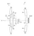
- FIG. 2is a diagram illustrating a cross-sectional configuration of the imaging unit. 3 is a view taken in the direction of arrow A in FIG.
- FIG. 4is a diagram illustrating a detailed cross-sectional configuration example of the pupil selection sensor.
- FIG. 5is a diagram illustrating an optical path of wide-angle image light incident on the various lenses.
- FIG. 6is a diagram illustrating an optical path of telephoto image light incident on the various lenses.
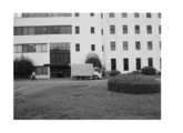
- FIG. 7is a diagram showing a wide-angle image taken simultaneously with the telephoto image.
- FIG. 8is a diagram showing a telephoto image taken simultaneously with a wide-angle image.
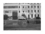
- FIG. 9is a diagram illustrating a wide-angle image in which interference occurs.
- FIG. 1is a perspective view showing a digital camera.
- FIG. 2is a diagram illustrating a cross-sectional configuration of the imaging unit. 3 is a view taken in the direction of
- FIG. 10is a diagram illustrating a telephoto image in which interference occurs.
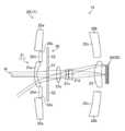
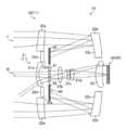
- FIG. 11is a diagram illustrating optical paths of wide-angle image light and telephoto image light that are incident on the various lenses and the pupil selection sensor.
- FIG. 12is a graph showing the photoelectric conversion characteristics of the first light receiving sensor and the second light receiving sensor when the first liquid crystal shutter is in the transmission state and the second liquid crystal shutter is in the light shielding state.
- FIG. 13is a diagram illustrating optical paths of wide-angle image light and telephoto image light that are incident on the various lenses and the pupil selection sensor.
- FIG. 14is a graph showing the photoelectric conversion characteristics of the first light receiving sensor and the second light receiving sensor when the first liquid crystal shutter is in a light shielding state and the second liquid crystal shutter is in a transmissive state.
- FIG. 15is a block diagram illustrating a functional configuration example of a digital camera.
- FIG. 16is a block diagram illustrating a detailed circuit configuration of the dynamic range expansion processing unit.
- FIG. 17is a diagram illustrating the signal level of the combined image data combined according to each dynamic range by the combining processing circuit.
- FIG. 18is a flowchart illustrating an example of an imaging method using a digital camera.
- FIG. 19is a block diagram illustrating a functional configuration example of a digital camera.
- FIG. 20is a block diagram illustrating a functional configuration example of a digital camera.
- FIG. 1is a perspective view illustrating a digital camera 10 (an example of an imaging apparatus) according to the present embodiment.
- the digital camera 10is provided with a multi-lens 11 having an optical axis L and a flash light emitting unit 12 for irradiating a subject with photographing auxiliary light on the front surface of the main body, and a release button 13 for executing an imaging operation is provided on the upper surface of the main body. Is provided.
- the digital camera 10In order for a photographer to photograph a subject using the digital camera 10, the digital camera 10 is held, the various lenses 11 are pointed at the subject, and the release button 13 is pressed.
- the subject image formed on the light receiving surface of the pupil selection sensor 24 (see FIG. 2) via the various lenses 11is photoelectrically converted by the pupil selection sensor 24 and read out as an image signal based on the operation of the release button 13. By subjecting this image signal to image processing, a captured image of the subject can be acquired.
- FIG. 2is a diagram illustrating a cross-sectional configuration of the imaging unit 14 including the various lenses 11 and the pupil selection sensor 24.
- the various lenses 11include a first optical system 21 and a second optical system 22 having mutually independent imaging characteristics.
- the first optical systemis an optical system having different focal lengths.
- 21 and the second optical system 22are configured. That is, the various lenses 11 of the present embodiment include a first optical system 21 (one of which is an example of a wide-angle optical system) configured by a wide-angle image capturing lens group and a second optical system 22 configured by a telephoto image capturing lens group. (The other is an example of a telephoto optical system).
- the first optical system 21 shown in FIG. 2is common to the first wide-angle lens 21a, the second wide-angle lens 21b, the third wide-angle lens 21c, the fourth wide-angle lens 21d, which are arranged on the same optical axis L.
- a lens 23is included.
- the second optical system 22includes a first telephoto reflector 22b provided with a first telephoto lens 22a, a first telephoto reflective mirror 22c, and a second telephoto reflector provided with a second telephoto reflective mirror 22e. 22d and the common lens 23 are comprised.
- FIG. 3is a view taken in the direction of arrow A in FIG.
- the first optical system 21(particularly the first wide-angle lens 21a, the second wide-angle lens 21b, the third wide-angle lens 21c and the fourth wide-angle lens 21d) and the second optical system 22 (particularly the first telephoto lens 22a,
- the first telescope reflector 22b, the first telescope reflector 22c, the second telescope reflector 22d, and the second telescope reflector 22e)are arranged concentrically, and the first optical system 21 is a central optical system.
- the second optical system 22forms a peripheral optical system arranged in a ring around the periphery of the first optical system 21.
- the common lens 23is disposed on the optical axis L and is shared between the first optical system 21 and the second optical system 22.
- the various lenses 11are the first optical system 21 and the second optical system 22 having the common optical axis L, and the first optical system 21 and the second optical system 22 having mutually different focal lengths and photographing field angles.
- An optical system 22is included.
- the pupil selection sensor 24is a directional sensor in which a plurality of light receiving sensors 25 (photoelectric conversion elements) have directivity with respect to the incident angle of light, and the plurality of light receiving sensors 25 are orthogonal to the optical axis L.
- the wide-angle image light W(see FIG. 5 as an example of the first incident light) that is two-dimensionally arranged in the direction to be incident and is incident through the first optical system 21 and the telephoto image that is incident through the second optical system 22
- Light Tan example of second incident light, see FIG. 6) is received simultaneously.
- FIG. 4is a diagram illustrating a detailed cross-sectional configuration example of the pupil selection sensor 24.
- the pupil selection sensor 24includes a first light receiving sensor 25a and a second light receiving sensor 25b having different angle sensitivity characteristics, and the first light receiving sensor 25a and the second light receiving sensor 25b are alternately arranged.
- the first light receiving sensor 25areceives the wide-angle image light W and outputs a first image signal for generating a wide-angle image (an example of the first image), and the second light-receiving sensor 25b receives the telephoto image light T. Then, a second image signal for generating a telephoto image (an example of the second image) is output.
- the plurality of first light receiving sensors 25aconstitute a first sensor group 24a that selectively receives the wide-angle image light W, and the plurality of second light receiving sensors 25b are second sensors that selectively receive the telephoto image light T.
- the group 24bis configured.
- Each of the first light receiving sensor 25a and the second light receiving sensor 25bhas a microlens 26, a photodiode 29, and an intermediate layer 27 in which the microlens 26 and the photodiode 29 are disposed.
- the intermediate layer 27is provided with a light shielding mask 28.
- the light shielding mask 28is disposed around the light receiving surface of the photodiode 29, and in the second light receiving sensor 25b, the light receiving surface of the photodiode 29 is disposed.
- a light shielding mask 28is disposed at the center. The arrangement of the light shielding mask 28 is determined according to which one of the first optical system 21 and the second optical system 22 corresponds, and each light shielding mask 28 blocks light from the optical system that does not correspond. The light from the corresponding optical system is received by the photodiode 29 without being blocked.
- the pupil selection sensor 24configured in this way actually has the telephoto image light T interfered with the first light receiving sensor 25a that selectively receives the wide-angle image light W, and selectively receives the telephoto image light T.
- Wide-angle image light Winterferes with the second light receiving sensor 25b.
- M and Nare numbers greater than 1
- the ratio of the sensitivity (interference) between the first light receiving sensor 25a and the second light receiving sensor 25b with respect to the wide-angle image light Wis M: 1
- the telephoto image lightAssume that the ratio of the sensitivity of the first light receiving sensor 25a and the second light receiving sensor 25b to T is 1: N.
- a plurality of light receiving sensorsfor selectively receiving the light that has passed through the corresponding optical system of the first optical system 21 and the second optical system 22 by pupil division by the light receiving sensor 25 including the light shielding mask 28.
- pupil divisionmay be realized by other means.
- a light shielding mask 28may be provided on the upstream side of the optical path of incident light from the micro lens 26, or a light shielding such as a liquid crystal shutter. Light shielding means other than the mask 28 may be used.
- members other than the light shielding mask 28may be provided in the intermediate layer 27.
- members other than the light shielding mask 28may be provided in the intermediate layer 27.
- wirings and / or circuitscan be provided in the intermediate layer 27.
- the pupil selection sensor 24is configured by R (red), G (green), and B (blue) color filters (optical filters) disposed with respect to the first light receiving sensor 25a and the second light receiving sensor 25b.
- a color filter arrayis provided, and an image (mosaic image) of each color obtained corresponding to the color array pattern of the color filter array is synchronized by the digital image signal processing unit 34 (see FIG. 13). Color wide-angle images and telephoto images can be obtained.
- the imaging unit 14includes a light shielding unit 50 including a first liquid crystal shutter 51 (an example of a second shutter) and a second liquid crystal shutter 52 (an example of a first shutter).
- the first liquid crystal shutter 51 and the second liquid crystal shutter 52are liquid crystal panels arranged concentrically in a direction orthogonal to the optical axis L, respectively.
- the first liquid crystal shutter 51 and the second liquid crystal shutter 52are configured to be switchable between a transmitting state that transmits incident light and a light blocking state that blocks light. This switching is performed by a light blocking shutter control unit 48 (see FIG. 15). ).
- the first liquid crystal shutter 51has a circular shape corresponding to the first optical system 21, and is located between the first wide-angle lens 21 a and the second wide-angle lens 21 b, and is used for the wide-angle image light W. It is arranged at the position of the optical path. That is, the first liquid crystal shutter 51 controls the passage and blocking of the wide-angle image light W according to the transmission state and the light shielding state.
- the first liquid crystal shutter 51is not limited to the one disposed inside the first optical system 21, and may be disposed before the first optical system 21 in the optical path of the wide-angle image light W. It may be arranged behind the first optical system 21 (between the first optical system 21 and the pupil selection sensor 24).
- the second liquid crystal shutter 52is annularly arranged around the first liquid crystal shutter 51 in correspondence with the second optical system 22, and the first telephoto reflection mirror 22c and the second telephoto reflection mirror 22e. Between the optical path and the position of the optical path of the telephoto image light T. That is, the second liquid crystal shutter 52 controls the passage and blocking of the telephoto image light T according to the transmission state and the light shielding state.
- the second liquid crystal shutter 52is not limited to the one disposed inside the second optical system 22, and may be disposed before the second optical system 22 in the optical path of the telephoto image light T. You may arrange
- the light shielding unit 50may configure the first liquid crystal shutter 51 and the second liquid crystal shutter 52 as a single liquid crystal panel, and individually switch the transmission state and the light shielding state for each region.
- FIG. 5is a diagram showing an optical path of the wide-angle image light W incident on the various lenses 11 (particularly the first optical system 21) and the pupil selection sensor 24 (particularly the first sensor group 24a (see FIG. 4)) shown in FIG. Yes, the first liquid crystal shutter 51 is in a transmissive state.
- the wide-angle image light Wis a first wide-angle lens 21a, a first liquid crystal shutter 51, a second wide-angle lens 21b, a third wide-angle lens 21c, and a fourth wide-angle lens.
- a wide-angle imageis formed on the first light receiving sensor 25a of the pupil selection sensor 24 by sequentially passing through the lens 21d and the common lens 23.
- FIG. 6is a diagram showing an optical path of the telephoto image light T incident on the various lenses 11 (particularly the second optical system 22) and the pupil selection sensor 24 (particularly the second sensor group 24b (see FIG. 4)) shown in FIG.
- the second liquid crystal shutter 52is in a transmissive state.
- the telephoto image light Tpasses (transmits) through the first telephoto lens 22a, is reflected by the first telephoto reflection mirror 22c, and then passes through the second liquid crystal shutter 52 to be second. It is reflected by the telephoto reflecting mirror 22e, passes through the second liquid crystal shutter 52 and the common lens 23, and forms a telephoto image on the second light receiving sensor 25b of the pupil selection sensor 24.
- the length in the direction of the optical axis L of the second optical system 22 for taking a telephoto image with a long focal lengthis reflected by each of the first telescopic reflecting mirror 22c and the second telescopic reflecting mirror 22e and folded back.
- the lengthcan be shortened.
- the wide angle image light W and the telephoto image light Tare selectively received by the pupil selection sensor 24, and the wide angle image and the telephoto image are received. Can be taken simultaneously.
- 7 and 8are diagrams showing an example of a wide-angle image and a telephoto image taken simultaneously, respectively. 7 and 8, when there is no interference between the wide-angle image and the telephoto image (the wide-angle image light W does not enter the second light receiving sensor 25b at all, and the telephoto image light T does not enter the first light receiving sensor. An example of a case in which no light is incident on 25a) is shown.
- FIG. 9 and FIG. 10are diagrams showing examples of a wide-angle image and a telephoto image when interference occurs.
- the telephoto imagehas interference in the wide-angle image, and in addition to the original subject image (small lorry in the center of the image), a false image (large image of the lorry) due to interference exists in the image. Appears slightly.
- the wide-angle imagealso has interference in the telephoto image, and in addition to the original subject (large lorry in the center of the image), a false image (small image of the lorry) due to interference is an image. It appears slightly in the center.
- the ratio of the sensitivity of the first light receiving sensor 25a and the second light receiving sensor 25b to the wide-angle image light Wis M: 1. Therefore, M / (M + 1) of the wide-angle image light W is received by the first light receiving sensor 25a, and 1 / (M + 1) interferes with the second light receiving sensor 25b.
- the ratio of the sensitivity of the first light receiving sensor 25a and the second light receiving sensor 25b to the telephoto image light Tis 1: N. Accordingly, N / (N + 1) of the telephoto image light T is received by the second light receiving sensor 25b, and 1 / (N + 1) interferes with the first light receiving sensor 25a.
- FIG. 11is a diagram illustrating optical paths of the wide-angle image light W and the telephoto image light T that are incident on the various lenses 11 and the pupil selection sensor 24 illustrated in FIG. 2.
- the first liquid crystal shutter 51is in a transmissive state
- the second liquid crystalThe case where the shutter 52 is in a light shielding state is shown.
- the telephoto image light Tpasses through the first telephoto lens 22a, is reflected by the first telephoto reflection mirror 22c, and then enters the second liquid crystal shutter 52.
- the second liquid crystal shutter 52is in a light-shielding state, the telephoto image light T incident on the second liquid crystal shutter 52 is blocked by the second liquid crystal shutter 52 and does not enter the second telephoto reflection mirror 22e. As a result, a telephoto image is not formed on the second light receiving sensor 25b of the pupil selection sensor 24.
- the wide-angle image light Wis transmitted through the first wide-angle lens 21a, the first liquid-crystal shutter 51, the first liquid-crystal shutter 51 of the first optical system 21, as in the case shown in FIG.
- a wide-angle imageis formed on the first light receiving sensor 25a of the pupil selection sensor 24 through the 2 wide-angle lens 21b, the third wide-angle lens 21c, the fourth wide-angle lens 21d, and the common lens 23 sequentially.
- the ratio of the sensitivity of the first light receiving sensor 25a and the second light receiving sensor 25b to the wide-angle image light Wis M: 1, M / (M + 1) of the wide-angle image light W is transmitted to the first light receiving sensor 25a.
- the second light receiving sensor 25breceives 1 / (M + 1) light. Therefore, a wide-angle image is formed on the first light receiving sensor 25a, and a wide-angle image is formed on the second light receiving sensor 25b with an exposure amount 1 / M of the wide-angle image photographed by the first light receiving sensor 25a.
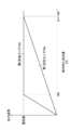
- FIG. 12is a graph showing the photoelectric conversion characteristics of the first light receiving sensor 25a and the second light receiving sensor 25b when the first liquid crystal shutter 51 is in the transmission state and the second liquid crystal shutter 52 is in the light shielding state.
- the relative incident light amount and the vertical axisindicate the output signal.
- the output of the first light receiving sensor 25aincreases proportionally as the relative incident light amount increases, and the output signal reaches a saturation value when the relative incident light amount is 100%. Thereafter, even if the relative incident light quantity increases, the output of the first light receiving sensor 25a becomes constant at the saturation value.
- the second light receiving sensor 25bhas a sensitivity of 1 / M with respect to the first light receiving sensor 25a, and reaches a saturation value when the relative incident light quantity is M ⁇ 100%.
- FIG. 13is a diagram illustrating optical paths of the wide-angle image light W and the telephoto image light T that are incident on the various lenses 11 and the pupil selection sensor 24 illustrated in FIG.
- the first liquid crystal shutter 51is in a light shielding state
- the second liquid crystal shutter 52is in a transmissive state.
- the wide-angle image light Wenters the first liquid crystal shutter 51 after passing through the first wide-angle lens 21 a of the first optical system 21.
- the first liquid crystal shutter 51since the first liquid crystal shutter 51 is in a light shielding state, the wide-angle image light W incident on the first liquid crystal shutter 51 is blocked by the first liquid crystal shutter 51 and does not enter the second wide-angle lens 21b. As a result, a wide-angle image is not formed on the first light receiving sensor 25a of the pupil selection sensor 24.
- the telephoto image light Tpasses through the second liquid crystal shutter 52 after passing through the first telephoto lens 22a, being reflected by the first telephoto reflection mirror 22c, since the second liquid crystal shutter 52 is in the transmission state. Then, it is reflected by the second telephoto reflecting mirror 22e, passes through the second liquid crystal shutter 52 and the common lens 23, and forms a telephoto image on the pupil selection sensor 24.
- N / (N + 1) of the telephoto image light Tis transmitted to the second light receiving sensor 25b.
- the first light receiving sensor 25areceives 1 / (N + 1) light. Accordingly, a telephoto image is formed on the second light receiving sensor 25b, and a telephoto image is formed on the first light receiving sensor 25a with an exposure amount 1 / N of the telephoto image taken by the second light receiving sensor 25b.
- FIG. 14is a graph showing the photoelectric conversion characteristics of the first light receiving sensor 25a and the second light receiving sensor 25b when the first liquid crystal shutter 51 is in a light shielding state and the second liquid crystal shutter 52 is in a transmissive state.
- the relative incident light amount and the vertical axisindicate the output signal.
- the output of the second light receiving sensor 25bincreases proportionally as the relative incident light amount increases, and the output signal reaches a saturation value when the relative incident light amount is 100%. Thereafter, even if the relative incident light quantity increases, the output of the second light receiving sensor 25b becomes constant at the saturation value.
- the first light receiving sensor 25ahas a sensitivity of 1 / N with respect to the second light receiving sensor 25b, and reaches a saturation value when the relative incident light quantity is N ⁇ 100%.
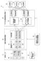
- FIG. 15is a block diagram illustrating a functional configuration example of the digital camera 10 according to the present embodiment.
- the digital camera 10includes an imaging / image acquisition unit 32 that acquires various images, and a digital image signal processing unit that performs signal processing on the various images.
- a recording unit 40for recording, displaying, and transmitting various images subjected to signal processing
- a display unit 42for displaying, and transmitting various images subjected to signal processing
- a display unit 42for transmitting various images subjected to signal processing
- a display unit 42for transmitting various images subjected to signal processing
- a display unit 42for a display unit 42
- a transmission unit 44a shooting mode selection / processing switching control unit 46 for switching the operation of the digital camera 10
- a light shielding unit 50has a light-shielding shutter controller 48 for controlling 50.
- the functions of the imaging / image acquisition unit 32, the digital image signal processing unit 34, the imaging mode selection / processing switching control unit 46, the light shielding shutter control unit 48, and the likeare processors such as a CPU (Central Processing Unit) in the digital camera 10. May be realized by the operation of a programmable logic device (PLD) or ASIC (Application Specific Integrated Circuit), which is a processor whose circuit configuration can be changed after manufacturing, such as an FPGA (Field Programmable Gate Array). It may be realized by a dedicated electric circuit which is a processor having a circuit configuration designed exclusively for executing a specific process such as the above or a combination thereof.
- PLDprogrammable logic device
- ASICApplication Specific Integrated Circuit
- Wide-angle image light W via the first various lens pupils 61 corresponding to the first optical system 21is received by the first sensor group 24a of the pupil selection sensor 24, and the second optical system 22 (FIG. 2).
- the telephoto image light T via the second various lens pupil 62 corresponding to the reference)is received by the second sensor group 24b of the pupil selection sensor 24.
- the imaging / image acquisition unit 32includes a pupil selection sensor 24.
- the imaging / image acquisition unit 32(an example of an image reading unit) acquires a first image signal from the first sensor group 24a of the pupil selection sensor 24 and acquires a second image signal from the second sensor group 24b.
- the first image signal and the second image signalare input to the digital image signal processing unit 34.
- the digital image signal processing unit 34includes an interference reduction processing unit 36 and a dynamic range expansion processing unit 38.
- the interference reduction processing unit 36uses the first liquid crystal shutter 51 and the second liquid crystal shutter 52 in the transmission state, and the second image signal that is interfering from the first image signal and the second image signal acquired by the imaging / image acquisition unit 32. Wide-angle image data with reduced and telephoto image data with reduced interfering first image signal.
- the dynamic range expansion processing unit 38expands the dynamic range from the first image signal and the second image signal acquired from the imaging / image acquisition unit 32 with either the first liquid crystal shutter 51 or the second liquid crystal shutter 52 being in a light-shielded state.
- the wide-angle image data or the telephoto image data with an expanded dynamic rangeis generated.
- the image data generated in the digital image signal processing unit 34is sent to the recording unit 40, the display unit 42, and / or the transmission unit 44.
- the recording unit 40includes a recording medium built in the digital camera 10 and / or a recording medium removable from the digital camera 10, and records the image data sent from the digital image signal processing unit 34 on these recording media.
- the display unit 42includes a liquid crystal monitor, and displays the image data sent from the digital image signal processing unit 34 on the liquid crystal monitor.
- the transmission unit 44transmits the image data sent from the digital image signal processing unit 34 via a communication means such as a wireless LAN (Local Area Network).
- a communication meanssuch as a wireless LAN (Local Area Network).
- the shooting mode selection / processing switching control unit 46corresponds to the shooting mode selected by the user of the digital camera 10 using an operation unit (not shown), and the imaging / image acquisition unit 32, the digital image signal processing unit 34, and The processing in the light shielding shutter control unit 48 is controlled.
- the light shielding shutter control unit 48(an example of the first light shielding control unit and an example of the second light shielding control unit) controls the transmission state and the light shielding state of the first liquid crystal shutter 51 and the second liquid crystal shutter 52.
- FIG. 16is a block diagram showing a detailed circuit configuration of the dynamic range expansion processing unit 38 shown in FIG.
- the dynamic range expansion processing unit 38includes offset processing units 100 and 102, linear matrix circuits 110 and 112, gain correction circuits 120 and 122, a synthesis processing circuit 130, and the like.
- the first image signal and the second image signalare input to the offset processing unit 100 and the offset processing unit 102, respectively, and are subjected to offset processing.
- the first image signal and the second image signal subjected to the offset processingare output to the linear matrix circuits 110 and 112, where a color tone correction process for correcting the spectral characteristics of the pupil selection sensor 24 is performed.
- the first image signal and the second image signal output from the linear matrix circuits 110 and 112are output to the gain correction circuits 120 and 122, respectively.
- the gain correction circuits 120 and 122perform white balance adjustment by applying a gain for white balance adjustment for each of the R, G, and B image signals.
- the first image signal and the second image signal output from the gain correction circuits 120 and 122are output to the synthesis processing circuit 130, respectively.
- the composition processing circuit 130mainly includes a tone conversion LUT (Look-Up Table) 132 for high-sensitivity image data, a tone conversion LUT 134 for low-sensitivity image data, and an adder 136.
- a tone conversion LUTLook-Up Table
- the gradation conversion LUTs 132 and 134are derived from six gradation conversion LUTs respectively corresponding to six dynamic ranges of M ⁇ 100% or less (100%, 130%, 170%, 230%, 300%, 400%).
- the corresponding gradation conversion LUTis selected from the six gradation conversion LUTs according to the enlargement ratio of the dynamic range selected by the operation unit (not shown).
- the first image signal and the second image signal input to the synthesis processing circuit 130are subjected to gradation conversion by the gradation conversion LUT selected based on the dynamic range expansion rate from the gradation conversion LUTs 132 and 134, respectively. It is output to the adder 136.
- the adder 136synthesizes (adds) the first image signal and the second image signal that have undergone gradation conversion by the gradation conversion LUTs 132 and 134.
- FIG. 17is a diagram showing the signal level of the combined image data synthesized by the synthesis processing circuit 130 according to each dynamic range. As shown in the figure, the maximum value of the signal level of the combined image data combined according to each dynamic range is the same, and the signal level smoothly changes from the luminance 0 to the maximum luminance of each dynamic range. Is synthesized as follows. That is, the tone conversion LUTs 132 and 134 perform tone conversion so that the synthesis result shown in FIG. 17 is obtained.
- the gradation conversion LUTs 132 and 134are configured by five gradation conversion LUTs corresponding to five dynamic ranges whose dynamic range is other than 100%.
- the synthesized R, G, B dot-sequential image signals output from the adder 136 of the synthesis processing circuit 130are converted into luminance signals Y and color difference signals Cr, Cb after being subjected to synchronization processing.
- the luminance signal Y and the color difference signals Cr and Cbare recorded in the recording unit 40, displayed on the display unit 42, and / or transmitted by the transmission unit 44.
- the enlargement ratio of the dynamic rangeis 400% at the maximum, but the dynamic range of the wide-angle image can be maximized at M ⁇ 100%, and the dynamic range of the telephoto image can be maximized at N ⁇ 100%.
- FIG. 18is a flowchart illustrating an example of an imaging method by the digital camera 10.
- the user of the digital camera 10can set the shooting mode of the digital camera 10 using an operation unit (not shown).
- the cameracan be selected from a wide-angle / telephoto simultaneous shooting mode, a wide-angle dynamic range expansion shooting mode, and a telephoto dynamic range expansion shooting mode.
- the photographing mode selection / process switching control unit 46determines the photographing mode in which the digital camera 10 is set in step S1. If the set shooting mode is the wide-angle / telephoto simultaneous shooting mode, the process proceeds to step S2. If the wide-angle dynamic range expansion shooting mode is set, the process proceeds to step S6. If the set shooting mode is the telephoto dynamic range expansion shooting mode, the process proceeds to step S10. .
- the light-shielding shutter control unit 48sets the first liquid crystal shutter 51 and the second liquid crystal shutter 52 to the transmissive state in step S2.
- the imaging / image acquisition unit 32acquires the first image signal from the first sensor group 24a of the pupil selection sensor 24, and the second sensor group 24b receives the first image signal. Two image signals are acquired (an example of an image reading process).
- the first image signal and the second image signalare input to the digital image signal processing unit 34, and interference reduction processing is performed by the interference reduction processing unit 36 in step S4.
- the crosstalk ratio of the first image signal and the second image signalis determined by the ratio of the sensitivity of the first light receiving sensor 25a and the second light receiving sensor 25b.
- the value of a certain pixel of the first image signalis T 1
- the value of the corresponding pixel (adjacent pixel) of the second image signalis W 1
- the value of the true pixel when there is no interference between these pixelsis T 2.
- W 2the following expressions 1 and 2 are established.
- T 1(M ⁇ T 2 + W 2 ) / (M + 1) (Formula 1)
- W 1(T 2 + N ⁇ W 2 ) / (N + 1) (Formula 2)
- step S5the wide-angle image on the basis of the above T 2, to obtain the telescopic image on the basis of W 2 (an example of an image generation step).
- step S6the light-shielding shutter control unit 48 sets the first liquid crystal shutter 51 to the transmissive state and the second liquid crystal shutter 52 to the light-shielding state.
- Setan example of a first light shielding control step.
- the imaging / image acquisition unit 32acquires the first image signal from the first sensor group 24a of the pupil selection sensor 24, and the second sensor group 24b receives the first image signal. Two image signals are acquired.
- the second liquid crystal shutter 52is in a light shielding state, the telephoto image light T does not enter the first sensor group 24a and the second sensor group 24b.
- the wide-angle image light Wis received by the first sensor group 24a at a ratio of M / (M + 1) and the second sensor group 24b at a ratio of 1 / (M + 1).
- the first image signal output from the first sensor group 24 a and the second image signal output from the second sensor group 24 bare input to the digital image signal processing unit 34.
- the dynamic range expansion processing unit 38 of the digital image signal processing unit 34performs dynamic range expansion processing on the first image signal and the second image signal in accordance with the dynamic range expansion rate selected by the operation unit (not shown).
- step S9a wide-angle image with an expanded dynamic range is acquired (an example of a dynamic range expansion process).
- a wide-angle image(an example of a third image) having a dynamic range M times the dynamic range of the wide-angle image in the wide-angle / telephoto simultaneous shooting mode can be acquired.
- the imageis not limited to an image having a dynamic range of M times, and a wide-angle image having a dynamic range of M times or less can be acquired.
- step S10the light shielding shutter control unit 48 sets the first liquid crystal shutter 51 to the light shielding state and the second liquid crystal shutter 52 to the transmission state. Set.
- the imaging / image acquisition unit 32acquires the first image signal from the first sensor group 24a of the pupil selection sensor 24, and the second sensor group 24b receives the first image signal.
- Two image signalsare acquired (an example of an image reading process).
- the wide-angle image light Wdoes not enter the first sensor group 24a and the second sensor group 24b.
- the telephoto image light Tis received by the first sensor group 24a at a ratio of 1 / (N + 1) and the second sensor group 24b at a ratio of N / (N + 1).
- the first image signal output from the first sensor group 24 a and the second image signal output from the second sensor group 24 bare input to the digital image signal processing unit 34.
- the dynamic range expansion processing unit 38 of the digital image signal processing unit 34performs dynamic range expansion processing on the first image signal and the second image signal according to the dynamic range expansion rate selected by the operation unit (not shown).
- step S13a telephoto image with an expanded dynamic range is acquired.
- a telephoto image(an example of a fourth image) having a dynamic range N times the dynamic range of the telephoto image in the wide-angle and telephoto simultaneous shooting mode can be acquired.
- the imageis not limited to an image having an N times dynamic range, and a telephoto image having an N times or less dynamic range can be acquired.
- Each image acquired in each shooting modecan be recorded, displayed, and / or transmitted by the recording unit 40, the display unit 42, and the transmission unit 44, respectively.
- a wide-angle image having a dynamic range of M times or lessis acquired in the wide-angle dynamic range expansion shooting mode
- a telephoto image having a dynamic range of N times or lessis acquired in the telephoto dynamic range expansion shooting mode. It is also possible to take a wide-angle image having a dynamic range and a telephoto image having a dynamic range of N times or less by operating the release button 13 once by the user.
- the first liquid crystal shutter 51 and the second liquid crystal shutter 52may be switched and sequentially switched for photographing.
- a wide-angle image with an expanded dynamic range and a telephoto image with an expanded dynamic rangecan be taken alternately in succession, and a wide-angle image and a telephoto image can be imaged.
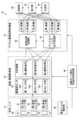
- FIG. 19is a block diagram illustrating a functional configuration example of the digital camera 10 according to the second embodiment.
- symbolis attached
- the various lenses 11have a first optical system (not shown) having a first characteristic, a second optical system (not shown) having a second characteristic, and a third optical system (not shown) having a third characteristic.
- a first liquid crystal shutter 51, a second liquid crystal shutter 52, and a third liquid crystal shutter 53 for switching light transmission and light shieldingare arranged. Has been.
- the pupil selection sensor 24is a directional sensor in which a plurality of light receiving sensors have directivity with respect to the incident angle of light.
- the pupil selection sensor 24includes a first sensor group 24a that selectively receives light via the first diverse lens pupil 61, a second sensor group 24b that selectively receives light via the second diverse lens pupil 62, And a third sensor group 24c that selectively receives light via the third diverse lens pupil 63.
- the first liquid crystal shutter 51, the second liquid crystal shutter 52, and the third liquid crystal shutter 53are in the transmissive state, the first light incident on the first optical system of the various lenses 11 corresponds to the first optical system.
- Lightis received by the first sensor group 24 a of the pupil selection sensor 24 through the one multi-lens pupil 61.
- the second light incident on the second optical systemis received by the second sensor group 24b via the second various lens pupil 62 corresponding to the second optical system, and the third light incident on the third optical system.
- the ratio of the sensitivity of the light receiving sensors constituting the first sensor group 24a, the light receiving sensors constituting the second sensor group 24b, and the light receiving sensors constituting the third sensor group 24cis as follows. Assume that M1: M2: M3, M4: M5: M6 for the second light, and M7: M8: M9 for the third light.
- the sensitivity ratio of the three images having the ratio M4: M5: M6is obtained for the second characteristic image. Images can be taken at the same time, and an image having the second characteristic with an expanded dynamic range according to the sensitivity ratio can be acquired.
- the sensitivity of each light receiving sensor of the pupil selection sensor 24 with respect to the light from the open pupil regionis set by opening a specific pupil region among the plurality of pupil regions and closing the other pupil regions.
- the pupil image in the open statecan be synthesized to obtain an image with a wide dynamic range.
- FIG. 20is a block diagram illustrating a functional configuration example of a digital camera 70 according to the third embodiment.
- symbolis attached
- the digital camera 70includes a photographing lens 71 having uniform characteristics in a region where light enters.
- the photographing lens 71includes a diaphragm 72 that forms a circular diaphragm aperture by a plurality of diaphragm blades and adjusts the amount of light incident on the pupil selection sensor 24 by changing the aperture diameter.
- the size of the aperture diameter of the diaphragm 72is controlled by the diaphragm controller 75.
- the pupil selection sensor 24is a directional sensor in which the plurality of light receiving sensors 25 have directivity with respect to the incident angle of light, and has the same configuration as the pupil selection sensor 24 shown in FIG.
- the digital camera 70includes a fine image generation unit 76 in the digital image signal processing unit 34.
- the fine image generation unit 76uses the first image signal acquired from the first sensor group 24a of the pupil selection sensor 24 and the second image signal acquired from the second sensor group 24b in parallel as different pixels in the image. Thus, fine image data is generated.
- the fine image datahas a resolution that is twice the resolution of the image data with the expanded dynamic range generated by the dynamic range expansion processing unit 38.
- the diaphragm control unit 75sets the diaphragm 72 to the open state. In this case, light incident from the vicinity of the center of the photographing lens 71 is incident on the first sensor group 24a of the pupil selection sensor 24 via the first lens pupil 73, and light incident from the vicinity of the vicinity of the center of the photographing lens 71 is obtained. Then, the light enters the second sensor group 24b through the second lens pupil 74.
- the imaging / image acquisition unit 32acquires a first image signal from the first sensor group 24a and acquires a second image signal from the second sensor group 24b.
- the first image signal and the second image signalare input to the digital image signal processing unit 34, and the fine image generation unit 76 generates fine image data.
- a fine imagecan be acquired by using both image signals of the first sensor group 24a and the second sensor group 24b in parallel.
- the ratio of the sensitivity of the first light receiving sensor 25a and the second light receiving sensor 25b to the incident light from the first lens pupil 73is M: 1.
- the aperture control unit 75stops the aperture diameter of the aperture 72 and blocks incident light from the second lens pupil 74. Accordingly, light that has passed through the second lens pupil 74 does not enter the pupil selection sensor 24.
- the ratio of the sensitivity of the first light receiving sensor 25a and the second light receiving sensor 25b to the incident light from the first lens pupil 73is M: 1. Therefore, M / (M + 1) of the incident light is received by the first light receiving sensor 25a, and 1 / (M + 1) interferes with the second light receiving sensor 25b.
- the imaging / image acquisition unit 32acquires the first image signal from the first sensor group 24a of the pupil selection sensor 24, and acquires the second image signal from the second sensor group 24b.
- the first image signal and the second image signalare input to the digital image signal processing unit 34.
- the dynamic range expansion processing unit 38 of the digital image signal processing unit 34performs dynamic range expansion processing on the first image signal and the second image signal in accordance with a dynamic range expansion rate selected by an operation unit (not shown).
- the various lenses 11 shown in FIG. 2may be used.
- the various lenses 11when the diaphragm 72 is opened, a wide-angle image and a telephoto image can be taken simultaneously, the aperture diameter of the diaphragm 72 is reduced, and incident light from the second optical system 22 is captured.
- an image in which the dynamic range of the wide-angle image is expandedcan be acquired. That is, an image with an expanded dynamic range having the imaging characteristics of the first optical system 21 can be acquired.
- the present inventioncan be widely applied to an imaging apparatus, an imaging method, and their application technologies capable of imaging a plurality of images using an imaging system in which each light receiving sensor has a directivity sensor having directivity with respect to an incident angle of light.
- the applicable technical fieldis not particularly limited.
- the present inventioncan be applied not only to an imaging device that captures an image in response to a user operation but also to an imaging device that automatically captures an image.
- the present inventioncan also be applied to an imaging apparatus that performs imaging.
- the imaging methodis a non-temporary recording medium such as a CD-ROM (Compact Disk-Read Only Memory) configured as a program for causing a computer to realize the above steps and storing a computer-readable code of the program. It is also possible to configure.
- a CD-ROMCompact Disk-Read Only Memory
Landscapes
- Physics & Mathematics (AREA)
- General Physics & Mathematics (AREA)
- Optics & Photonics (AREA)
- Signal Processing (AREA)
- Multimedia (AREA)
- Engineering & Computer Science (AREA)
- Nonlinear Science (AREA)
- Spectroscopy & Molecular Physics (AREA)
- Crystallography & Structural Chemistry (AREA)
- Chemical & Material Sciences (AREA)
- Studio Devices (AREA)
- Cameras In General (AREA)
- Shutters For Cameras (AREA)
- Lenses (AREA)
Abstract
Description
Translated fromJapanese本発明は、撮像装置、撮像方法、プログラム、及び非一時的記録媒体に関し、特に各受光センサが光の入射角に関して指向性を有する指向性センサを使用して複数の画像を同時に撮影する技術に関する。The present invention relates to an imaging apparatus, an imaging method, a program, and a non-temporary recording medium, and more particularly, to a technique for simultaneously capturing a plurality of images using a directional sensor in which each light receiving sensor has directivity with respect to an incident angle of light. .
領域により異なる撮像特性を有する光学系と指向性センサを備える撮像系により、撮像特性が異なる複数の画像を同時に取得可能な撮像システムが提案されている。指向性センサは、理想的には、想定された瞳領域からの光だけを感じるように製作されるが、実際には混信が生じて、他の瞳領域からの光にも感じてしまう。There has been proposed an imaging system that can simultaneously acquire a plurality of images having different imaging characteristics by using an optical system having different imaging characteristics depending on a region and an imaging system including a directional sensor. Ideally, the directivity sensor is manufactured so that only light from the assumed pupil region is sensed, but in reality, interference occurs and the light from other pupil regions is also felt.
このような課題に対し、特許文献1には、複数の領域の内の一の領域に対応する受光センサの撮像信号から一の領域に対応する画像を生成し、生成された画像の補正を行う際に、一の領域に対応して生成された画像から一の領域以外の領域を通過した光束の影響を除去する技術が記載されている。In order to deal with such a problem, Patent Literature 1 generates an image corresponding to one area from an imaging signal of a light receiving sensor corresponding to one area among a plurality of areas, and corrects the generated image. At the same time, a technique for removing the influence of a light beam that has passed through a region other than one region from an image generated corresponding to the one region is described.
しかしながら、特許文献1に記載の技術では、高輝度の被写体がある場合には、信号飽和の影響によって混信成分を除去することができず、出力画像の画質を劣化させてしまうという問題があった。また、高輝度の被写体に白トビが発生しないように、ダイナミックレンジを拡大した画像を取得するためには、露光時間の異なる2枚の画像を撮影する必要があった。However, the technique described in Patent Document 1 has a problem that when there is a high-luminance subject, the interference component cannot be removed due to the influence of signal saturation, and the image quality of the output image is deteriorated. . Further, in order to acquire an image with an expanded dynamic range so as not to cause white stripes in a high-luminance subject, it is necessary to take two images with different exposure times.
本発明はこのような事情に鑑みてなされたもので、各受光センサが光の入射角に関して指向性を有する指向性センサを備える撮像系により複数の画像を同時に撮影し、ダイナミックレンジを拡大した画像を取得する撮像装置、撮像方法、プログラム、及び非一時的記録媒体を提供することを目的とする。The present invention has been made in view of such circumstances, and each of the light receiving sensors is an image obtained by simultaneously capturing a plurality of images with an imaging system including a directional sensor having directivity with respect to the incident angle of light, and expanding the dynamic range. An object is to provide an imaging device, an imaging method, a program, and a non-temporary recording medium.
上記目的を達成するために撮像装置の一の態様は、それぞれ異なる領域に設けられた第1光学系と第2光学系とを備える撮影レンズと、複数の第1受光センサと複数の第2受光センサとが2次元状に配列された指向性センサであって、M及びNを1より大きい数とすると、第1光学系を介して入射した第1入射光に対する第1受光センサと第2受光センサとの感度の比率がM:1であり、第2光学系を介して入射した第2入射光に対する第1受光センサと第2受光センサとの感度の比率が1:Nである指向性センサと、複数の第1受光センサから得られる第1画像信号と複数の第2受光センサから得られる第2画像信号とを取得する画像読み出し部と、第1画像信号から第1画像を生成し、第2画像信号から第2画像を生成する画像生成部と、第2入射光の指向性センサへの入射又は遮光を制御する第1遮光制御部と、第2入射光を遮光した状態で第1画像信号と第2画像信号とを取得し、第1画像のダイナミックレンジのM倍以下のダイナミックレンジを有する第3画像を生成するダイナミックレンジ拡大処理部と、を備えた。In order to achieve the above object, one aspect of an imaging apparatus includes a photographic lens including a first optical system and a second optical system provided in different regions, a plurality of first light receiving sensors, and a plurality of second light receiving elements. When the sensors are two-dimensionally arranged directional sensors, and M and N are numbers larger than 1, the first light receiving sensor and the second light receiving for the first incident light incident through the first optical system. A directional sensor in which the ratio of sensitivity to the sensor is M: 1 and the ratio of the sensitivity of the first light receiving sensor and the second light receiving sensor to the second incident light incident through the second optical system is 1: N. A first image signal obtained from the plurality of first light receiving sensors and a second image signal obtained from the plurality of second light receiving sensors, a first image is generated from the first image signal, An image generation unit that generates a second image from the second image signal The first image signal and the second image signal are acquired in a state in which the second incident light is shielded, and the first image signal is obtained by shielding the second incident light. A dynamic range expansion processing unit that generates a third image having a dynamic range that is equal to or less than M times the dynamic range.
本態様によれば、第1光学系を介して入射した第1入射光に対する第1受光センサと第2受光センサとの感度の比率がM:1である指向性センサによって、第2入射光を遮光した状態で複数の第1受光センサと第2受光センサとから第1画像信号と第2画像信号とを取得し、第1画像信号から生成される第1画像のダイナミックレンジのM倍以下のダイナミックレンジを有する第3画像を生成するようにしたので、受光センサが光の入射角に関して指向性を有する指向性センサを備える撮像系により、ダイナミックレンジを拡大した画像を撮影することができる。According to this aspect, the second incident light is transmitted by the directional sensor whose sensitivity ratio of the first light receiving sensor and the second light receiving sensor to the first incident light incident through the first optical system is M: 1. The first image signal and the second image signal are acquired from the plurality of first light receiving sensors and the second light receiving sensor in a light-shielded state, and are equal to or less than M times the dynamic range of the first image generated from the first image signal. Since the third image having the dynamic range is generated, it is possible to capture an image with an expanded dynamic range by the imaging system in which the light receiving sensor includes a directivity sensor having directivity with respect to the incident angle of light.
第1遮光制御部は、光の透過状態と遮光状態とを切り替える第1シャッタを備えることが好ましい。これにより、第2入射光の指向性センサへの入射又は遮光を適切に制御することができる。It is preferable that the first light shielding control unit includes a first shutter that switches between a light transmission state and a light shielding state. Thereby, the incidence or shading of the second incident light on the directivity sensor can be appropriately controlled.
第1シャッタは、第1入射光の光路に配置されることが好ましい。これにより、第2入射光の指向性センサへの入射又は遮光を適切に制御することができる。The first shutter is preferably disposed in the optical path of the first incident light. Thereby, the incidence or shading of the second incident light on the directivity sensor can be appropriately controlled.
第1入射光の指向性センサへの入射又は遮光を制御する第2遮光制御部を備え、ダイナミックレンジ拡大処理部は、第2入射光を入射させ、かつ第1入射光を遮光した状態で第1画像信号と第2画像信号とを取得し、第2画像のダイナミックレンジのN倍のダイナミックレンジを有する第4画像を生成することが好ましい。これにより、第2入射光によるダイナミックレンジを拡大した画像を撮影することができる。A second light shielding control unit configured to control the incidence or shielding of the first incident light on the directivity sensor, and the dynamic range expansion processing unit receives the second incident light and blocks the first incident light in a state of shielding the first incident light. Preferably, the first image signal and the second image signal are acquired, and a fourth image having a dynamic range N times the dynamic range of the second image is generated. Thereby, the image which expanded the dynamic range by 2nd incident light can be image | photographed.
第2遮光制御部は、光の透過状態と遮光状態とを切り替える第2シャッタを備えることが好ましい。これにより、第1入射光の指向性センサへの入射又は遮光を適切に制御することができる。It is preferable that the second light shielding control unit includes a second shutter that switches between a light transmission state and a light shielding state. As a result, it is possible to appropriately control the incidence or shielding of the first incident light on the directivity sensor.
第2シャッタは、第2入射光の光路に配置されることが好ましい。これにより、第1入射光の指向性センサへの入射又は遮光を適切に制御することができる。The second shutter is preferably arranged in the optical path of the second incident light. As a result, it is possible to appropriately control the incidence or shielding of the first incident light on the directivity sensor.
第1光学系及び第2光学系は、互いに異なる撮像特性を有することが好ましい。これにより、互いに異なる撮像特性を有する画像を同時に撮影することができる。It is preferable that the first optical system and the second optical system have different imaging characteristics. As a result, images having different imaging characteristics can be taken simultaneously.
第1光学系及び第2光学系は、一方が広角光学系であり、他方が広角光学系より焦点距離が長い望遠光学系であることが好ましい。これにより、広角画像と望遠画像とを同時に撮影することができる。It is preferable that one of the first optical system and the second optical system is a wide-angle optical system, and the other is a telephoto optical system having a longer focal length than the wide-angle optical system. Thereby, a wide-angle image and a telephoto image can be taken simultaneously.
撮影レンズは、第1光学系が中央部に配置され、第2光学系が第1光学系の周辺部に環状に配置されることが好ましい。これにより、第1光学系と第2光学系とを適切に配置し、また、第2入射光の指向性センサへの入射又は遮光を適切に制御することができる。In the photographing lens, it is preferable that the first optical system is arranged in the center and the second optical system is arranged in an annular shape in the periphery of the first optical system. Thereby, the first optical system and the second optical system can be appropriately arranged, and the incidence or shading of the second incident light to the directional sensor can be appropriately controlled.
指向性センサへ入射する光量を調節するための絞りを備え、第1遮光制御部は、絞りによって第2入射光の指向性センサへの入射又は遮光を制御してもよい。これにより、第2入射光の指向性センサへの入射又は遮光を適切に制御することができる。A diaphragm for adjusting the amount of light incident on the directional sensor may be provided, and the first light shielding control unit may control the incidence or shielding of the second incident light on the directional sensor by the diaphragm. Thereby, the incidence or shading of the second incident light on the directivity sensor can be appropriately controlled.
上記目的を達成するために撮像方法の一の態様は、それぞれ異なる領域に設けられた第1光学系と第2光学系とを備える撮影レンズと、複数の第1受光センサと複数の第2受光センサとが2次元状に配列された指向性センサであって、M及びNを1より大きい数とすると、第1光学系を介して入射した第1入射光に対する第1受光センサと第2受光センサとの感度の比率がM:1であり、第2光学系を介して入射した第2入射光に対する第1受光センサと第2受光センサとの感度の比率が1:Nである指向性センサと、を備えた撮像装置の撮像方法であって、複数の第1受光センサから得られる第1画像信号と複数の第2受光センサから得られる第2画像信号とを取得する画像読み出し工程と、第1画像信号から第1画像を生成し、第2画像信号から第2画像を生成する画像生成工程と、第2入射光の指向性センサへの入射又は遮光を制御する第1遮光制御工程と、第2入射光を遮光した状態で第1画像信号と第2画像信号とを取得し、第1画像のダイナミックレンジのM倍以下のダイナミックレンジを有する第3画像を生成するダイナミックレンジ拡大処理工程と、を備えた。In order to achieve the above object, one aspect of an imaging method includes a photographing lens including a first optical system and a second optical system provided in different regions, a plurality of first light receiving sensors, and a plurality of second light receiving elements. When the sensors are two-dimensionally arranged directional sensors, and M and N are numbers larger than 1, the first light receiving sensor and the second light receiving for the first incident light incident through the first optical system. A directional sensor in which the ratio of sensitivity to the sensor is M: 1 and the ratio of the sensitivity of the first light receiving sensor and the second light receiving sensor to the second incident light incident through the second optical system is 1: N. An image reading method for acquiring a first image signal obtained from a plurality of first light receiving sensors and a second image signal obtained from a plurality of second light receiving sensors; A first image is generated from the first image signal, and the second image An image generation step for generating a second image from the signal, a first light-blocking control step for controlling the incidence or light-blocking of the second incident light on the directional sensor, and the first image signal in a state where the second incident light is blocked. A dynamic range expansion processing step of acquiring a second image signal and generating a third image having a dynamic range equal to or less than M times the dynamic range of the first image.
本態様によれば、第1光学系を介して入射した第1入射光に対する第1受光センサと第2受光センサとの感度の比率がM:1である指向性センサによって、第2入射光を遮光した状態で複数の第1受光センサと第2受光センサとから第1画像信号と第2画像信号とを取得し、第1画像信号から生成される第1画像のダイナミックレンジのM倍以下のダイナミックレンジを有する第3画像を生成するようにしたので、受光センサが光の入射角に関して指向性を有する指向性センサを備える撮像系により、ダイナミックレンジを拡大した画像を撮影することができる。According to this aspect, the second incident light is transmitted by the directional sensor whose sensitivity ratio of the first light receiving sensor and the second light receiving sensor to the first incident light incident through the first optical system is M: 1. The first image signal and the second image signal are acquired from the plurality of first light receiving sensors and the second light receiving sensor in a light-shielded state, and are equal to or less than M times the dynamic range of the first image generated from the first image signal. Since the third image having the dynamic range is generated, it is possible to capture an image with an expanded dynamic range by the imaging system in which the light receiving sensor includes a directivity sensor having directivity with respect to the incident angle of light.
撮像方法を撮像装置に実行させるプログラムも本態様に含まれる。また、プログラムのコンピュータ読み取り可能なコードが記録された、非一時的記録媒体も本態様に含まれる。A program that causes an imaging apparatus to execute an imaging method is also included in this aspect. A non-transitory recording medium in which a computer-readable code of the program is recorded is also included in this aspect.
本発明によれば、各受光センサが光の入射角に関して指向性を有する指向性センサを備える撮像系により、ダイナミックレンジを拡大した画像を撮影することができる。According to the present invention, an image with an expanded dynamic range can be taken by an imaging system in which each light receiving sensor includes a directional sensor having directivity with respect to the incident angle of light.
以下、添付図面に従って本発明の好ましい実施形態について説明する。Hereinafter, preferred embodiments of the present invention will be described with reference to the accompanying drawings.
〔デジタルカメラの構成〕
図1は、本実施形態に係るデジタルカメラ10(撮像装置の一例)を示す斜視図である。デジタルカメラ10は、光軸Lを有する多様レンズ11及び被写体に撮影補助光を照射するフラッシュ発光部12が本体の前面に設けられており、撮像動作を実行させるためのレリーズボタン13が本体の上面に設けられている。[Configuration of digital camera]
FIG. 1 is a perspective view illustrating a digital camera 10 (an example of an imaging apparatus) according to the present embodiment. The
撮影者がデジタルカメラ10を用いて被写体を撮影するには、デジタルカメラ10を保持して多様レンズ11を被写体に向け、レリーズボタン13を押せばよい。多様レンズ11を介して瞳選択センサ24(図2参照)の受光面に結像した被写体像は、瞳選択センサ24において光電変換され、レリーズボタン13の操作に基づいて、画像信号として読み出される。この画像信号に画像処理を施すことにより、被写体の撮影画像を取得することができる。In order for a photographer to photograph a subject using the
〔撮像部の構成〕
図2は、多様レンズ11及び瞳選択センサ24を備える撮像部14の断面構成を示す図である。(Configuration of imaging unit)
FIG. 2 is a diagram illustrating a cross-sectional configuration of the
多様レンズ11(撮影レンズの一例)は、相互に独立した撮像特性を有する第1光学系21及び第2光学系22を含み、特に本実施形態では焦点距離が互いに異なる光学系によって第1光学系21及び第2光学系22が構成される。すなわち、本実施形態の多様レンズ11は、広角画像撮影レンズ群によって構成される第1光学系21(一方が広角光学系の一例)と、望遠画像撮影レンズ群によって構成される第2光学系22(他方が望遠光学系の一例)とを含んでいる。The various lenses 11 (an example of a photographic lens) include a first
図2に示す第1光学系21は、同一の光軸L上に配置される第1広角用レンズ21a、第2広角用レンズ21b、第3広角用レンズ21c、第4広角用レンズ21d及び共通レンズ23を含んで構成される。一方、第2光学系22は、第1望遠用レンズ22a、第1望遠用反射ミラー22cが設けられる第1望遠用反射体22b、第2望遠用反射ミラー22eが設けられる第2望遠用反射体22d、及び共通レンズ23を含んで構成される。The first
図3は、図2のA矢視図である。第1光学系21(特に第1広角用レンズ21a、第2広角用レンズ21b、第3広角用レンズ21c及び第4広角用レンズ21d)と第2光学系22(特に第1望遠用レンズ22a、第1望遠用反射体22b、第1望遠用反射ミラー22c、第2望遠用反射体22d及び第2望遠用反射ミラー22e)とは、同心状に配置され、第1光学系21は中央光学系を形成し、第2光学系22は第1光学系21の周辺部に環状に配置された周辺光学系を形成する。なお、共通レンズ23は、光軸L上に配置され、第1光学系21と第2光学系22との間で共用される。FIG. 3 is a view taken in the direction of arrow A in FIG. The first optical system 21 (particularly the first wide-
このように、多様レンズ11は、共通の光軸Lを有する第1光学系21及び第2光学系22であって、相互に異なる焦点距離及び撮影画角を有する第1光学系21及び第2光学系22を含んでいる。As described above, the
図2の説明に戻り、瞳選択センサ24は、複数の受光センサ25(光電変換素子)が光の入射角に関して指向性を有する指向性センサであり、複数の受光センサ25が光軸Lと直交する方向に2次元状に配置され、第1光学系21を介して入射する広角画像光W(第1入射光の一例、図5参照)と、第2光学系22を介して入射する望遠画像光T(第2入射光の一例、図6参照)とを同時に受光する。Returning to the description of FIG. 2, the
図4は、瞳選択センサ24の詳細な断面構成例を示す図である。瞳選択センサ24は、角度感度特性が異なる第1受光センサ25aと第2受光センサ25bとを備えており、第1受光センサ25aと第2受光センサ25bとは、交互に配置されている。FIG. 4 is a diagram illustrating a detailed cross-sectional configuration example of the
第1受光センサ25aは、広角画像光Wを受光して広角画像(第1画像の一例)を生成するための第1画像信号を出力し、第2受光センサ25bは、望遠画像光Tを受光して望遠画像(第2画像の一例)を生成するための第2画像信号を出力する。The first
複数の第1受光センサ25aは、広角画像光Wを選択的に受光する第1センサ群24aを構成し、複数の第2受光センサ25bは、望遠画像光Tを選択的に受光する第2センサ群24bを構成する。The plurality of first
第1受光センサ25a及び第2受光センサ25bの各々は、マイクロレンズ26、フォトダイオード29、及びマイクロレンズ26とフォトダイオード29とが配置される中間層27を有する。中間層27には遮光マスク28が設けられており、第1受光センサ25aではフォトダイオード29の受光面の周辺部に遮光マスク28が配置され、第2受光センサ25bではフォトダイオード29の受光面の中央部に遮光マスク28が配置される。遮光マスク28の配置は、第1光学系21及び第2光学系22のうちのいずれに対応するかに応じて決定され、各遮光マスク28は、対応しない光学系からの光を遮断する一方で対応する光学系からの光を遮断することなくフォトダイオード29に受光させる。Each of the first
このように構成された瞳選択センサ24は、実際には、広角画像光Wを選択的に受光する第1受光センサ25aに望遠画像光Tが混信し、望遠画像光Tを選択的に受光する第2受光センサ25bに広角画像光Wが混信する。本実施形態では、M及びNを1より大きい数とすると、広角画像光Wに対する第1受光センサ25aと第2受光センサ25bとの感度(混信)の比率がM:1であり、望遠画像光Tに対する第1受光センサ25aと第2受光センサ25bとの感度の比率が1:Nであるとする。例えば、M=10、N=10とすることができる。なお、MとNとは異なる値であってもよい。The
なお、ここでは、遮光マスク28を含む受光センサ25によって、第1光学系21及び第2光学系22のうち対応する光学系を通過した光を瞳分割して選択的に受光する複数の受光センサを実現しているが、他の手段によって瞳分割を実現してもよい。例えば、共通レンズ23(図2参照)とマイクロレンズ26との間のように、マイクロレンズ26よりも入射光の光路の上流側に遮光マスク28が設けられてもよいし、液晶シャッタ等の遮光マスク28以外の遮光手段を用いてもよい。Here, a plurality of light receiving sensors for selectively receiving the light that has passed through the corresponding optical system of the first
また、中間層27には遮光マスク28以外の部材を設けてもよく、例えば配線及び/又は回路類を中間層27に設けることができる。Further, members other than the
瞳選択センサ24には、第1受光センサ25a及び第2受光センサ25bに対して配設されたR(赤),G(緑),B(青)のカラーフィルタ(光学フィルタ)により構成されるカラーフィルタ配列が設けられており、このカラーフィルタ配列の色配列パターンに対応して得られる各色の画像(モザイク画像)をデジタル画像信号処理部34(図13参照)が同時化処理することにより、カラーの広角画像及び望遠画像が得られるようになっている。The
再び図2の説明に戻り、撮像部14は、第1液晶シャッタ51(第2シャッタの一例)及び第2液晶シャッタ52(第1シャッタの一例)からなる遮光部50を備えている。第1液晶シャッタ51及び第2液晶シャッタ52は、それぞれ光軸Lと直交する方向に同心状に配置された液晶パネルである。第1液晶シャッタ51及び第2液晶シャッタ52は、入射する光を透過する透過状態及び光を遮光する遮光状態に切り替え可能に構成されており、この切り替えは、遮光シャッタ制御部48(図15参照)によって制御される。2 again, the
第1液晶シャッタ51は第1光学系21に対応した円形の形状を有しており、第1広角用レンズ21aと第2広角用レンズ21bとの間の位置であって、広角画像光Wの光路の位置に配置されている。すなわち、第1液晶シャッタ51は、透過状態及び遮光状態により、広角画像光Wの通過及び遮断を制御する。なお、第1液晶シャッタ51は、第1光学系21の内部に配置されるものに限定されず、広角画像光Wの光路の第1光学系21よりも前段に配置されてもよいし、第1光学系21よりも後段(第1光学系21と瞳選択センサ24との間)に配置されていてもよい。The first
また、第2液晶シャッタ52は、第2光学系22に対応して、第1液晶シャッタ51の周辺部に環状に配置されており、第1望遠用反射ミラー22cと第2望遠用反射ミラー22eとの間の位置であって、望遠画像光Tの光路の位置に配置されている。すなわち、第2液晶シャッタ52は、透過状態及び遮光状態により、望遠画像光Tの通過及び遮断を制御する。第2液晶シャッタ52についても、第2光学系22の内部に配置されるものに限定されず、望遠画像光Tの光路の第2光学系22よりも前段に配置されてもよいし、第2光学系22よりも後段(第2光学系22と瞳選択センサ24との間)に配置されていてもよい。The second
遮光部50は、第1液晶シャッタ51及び第2液晶シャッタ52を1枚の液晶パネルとして構成し、それぞれの領域について個別に透過状態及び遮光状態を切り替えてもよい。The
〔撮像部の作用〕
<第1液晶シャッタ及び第2液晶シャッタが透過状態の場合>
図5は、図2に示す多様レンズ11(特に第1光学系21)及び瞳選択センサ24(特に第1センサ群24a(図4参照))に入射する広角画像光Wの光路を示す図であり、第1液晶シャッタ51が透過状態である場合を示している。同図に示すように、広角画像光Wは、第1光学系21の第1広角用レンズ21a、第1液晶シャッタ51、第2広角用レンズ21b、第3広角用レンズ21c、第4広角用レンズ21d及び共通レンズ23を順次通過し、瞳選択センサ24の第1受光センサ25aに広角画像が結像する。(Operation of the imaging unit)
<When the first liquid crystal shutter and the second liquid crystal shutter are in the transmissive state>
FIG. 5 is a diagram showing an optical path of the wide-angle image light W incident on the various lenses 11 (particularly the first optical system 21) and the pupil selection sensor 24 (particularly the
図6は、図2に示す多様レンズ11(特に第2光学系22)及び瞳選択センサ24(特に第2センサ群24b(図4参照))に入射する望遠画像光Tの光路を示す図であり、第2液晶シャッタ52が透過状態である場合を示している。同図に示すように、望遠画像光Tは、第1望遠用レンズ22aを通過(透過)して第1望遠用反射ミラー22cに反射された後、第2液晶シャッタ52を通過して第2望遠用反射ミラー22eにより反射され、第2液晶シャッタ52、共通レンズ23を通過し、瞳選択センサ24の第2受光センサ25bに望遠画像が結像する。第1望遠用反射ミラー22c及び第2望遠用反射ミラー22eの各々により反射されて光路が折り返されることにより、焦点距離の長い望遠画像撮影用の第2光学系22の光軸Lの方向に関する長さを短くすることができる。6 is a diagram showing an optical path of the telephoto image light T incident on the various lenses 11 (particularly the second optical system 22) and the pupil selection sensor 24 (particularly the
したがって、第1液晶シャッタ51及び第2液晶シャッタ52が共に透過状態である場合には、瞳選択センサ24において広角画像光Wと望遠画像光Tとを選択的に受光し、広角画像と望遠画像を同時に撮影することができる。Therefore, when both the first
図7及び図8は、それぞれ同時に撮影した広角画像と望遠画像との一例を示す図である。なお、図7及び図8では、広角画像と望遠画像との間で混信が生じていない場合(広角画像光Wが第2受光センサ25bに全く入射せず、望遠画像光Tが第1受光センサ25aに全く入射しない場合)の例を示している。7 and 8 are diagrams showing an example of a wide-angle image and a telephoto image taken simultaneously, respectively. 7 and 8, when there is no interference between the wide-angle image and the telephoto image (the wide-angle image light W does not enter the second
これに対し、図9及び図10は、それぞれ混信が生じている場合の広角画像と望遠画像との一例を示す図である。図9に示すように、広角画像中に望遠画像が混信しており、本来の被写体像(画像中央の小さな貨物自動車)の他に、混信による偽像(貨物自動車の大きな像)が画像内にうっすらと現れている。一方、図10に示すように、望遠画像中にも広角画像が混信しており、本来の被写体(画像中央の大きな貨物自動車)の他に、混信による偽像(貨物自動車の小さな像)が画像中央にうっすらと現れている。On the other hand, FIG. 9 and FIG. 10 are diagrams showing examples of a wide-angle image and a telephoto image when interference occurs. As shown in FIG. 9, the telephoto image has interference in the wide-angle image, and in addition to the original subject image (small lorry in the center of the image), a false image (large image of the lorry) due to interference exists in the image. Appears slightly. On the other hand, as shown in FIG. 10, the wide-angle image also has interference in the telephoto image, and in addition to the original subject (large lorry in the center of the image), a false image (small image of the lorry) due to interference is an image. It appears slightly in the center.
前述のように、本実施形態に係る瞳選択センサ24は、広角画像光Wに対する第1受光センサ25aと第2受光センサ25bとの感度の比率がM:1である。したがって、広角画像光WのM/(M+1)は第1受光センサ25aに受光され、1/(M+1)は第2受光センサ25bに混信する。また、望遠画像光Tに対する第1受光センサ25aと第2受光センサ25bとの感度の比率が1:Nである。したがって、望遠画像光TのN/(N+1)は第2受光センサ25bに受光され、1/(N+1)は第1受光センサ25aに混信する。As described above, in the
<第1液晶シャッタが透過状態、第2液晶シャッタが遮光状態の場合>
図11は、図2に示す多様レンズ11及び瞳選択センサ24に入射する広角画像光W及び望遠画像光Tの光路を示す図であり、第1液晶シャッタ51が透過状態であり、第2液晶シャッタ52が遮光状態の場合を示している。<When the first liquid crystal shutter is in a transmissive state and the second liquid crystal shutter is in a light shielding state>
FIG. 11 is a diagram illustrating optical paths of the wide-angle image light W and the telephoto image light T that are incident on the
望遠画像光Tは、第1望遠用レンズ22aを通過し、第1望遠用反射ミラー22cに反射された後、第2液晶シャッタ52に入射する。ここでは、第2液晶シャッタ52は遮光状態であるため、第2液晶シャッタ52に入射した望遠画像光Tは第2液晶シャッタ52により遮断され、第2望遠用反射ミラー22eには入射しない。その結果、瞳選択センサ24の第2受光センサ25bには望遠画像が結像しない。The telephoto image light T passes through the
一方、第1液晶シャッタ51は透過状態であるため、図5に示した場合と同様に、広角画像光Wは、第1光学系21の第1広角用レンズ21a、第1液晶シャッタ51、第2広角用レンズ21b、第3広角用レンズ21c、第4広角用レンズ21d及び共通レンズ23を順次通過し、瞳選択センサ24の第1受光センサ25aに広角画像が結像する。On the other hand, since the first
ここで、広角画像光Wに対する第1受光センサ25aと第2受光センサ25bとの感度の比率はM:1であるため、広角画像光WのうちM/(M+1)は第1受光センサ25aに受光され、1/(M+1)は第2受光センサ25bが受光する。したがって、第1受光センサ25aに広角画像が結像するとともに、第2受光センサ25bに、第1受光センサ25aで撮影される広角画像の1/Mの露光量により広角画像が結像する。Here, since the ratio of the sensitivity of the first
図12は、第1液晶シャッタ51を透過状態、及び第2液晶シャッタ52を遮光状態とした場合の第1受光センサ25aと第2受光センサ25bの光電変換特性を示すグラフであり、横軸は相対的入射光量、縦軸は出力信号を示している。FIG. 12 is a graph showing the photoelectric conversion characteristics of the first
第1受光センサ25aの出力は、相対的入射光量が増加するに従って比例して増加し、相対的入射光量が100%の場合に出力信号が飽和値に達する。以後、相対的入射光量が増加しても、第1受光センサ25aの出力は飽和値において一定となる。The output of the first
一方、第2受光センサ25bは、第1受光センサ25aに対して感度が1/Mであり、相対的入射光量がM×100%の場合に飽和値に達する。On the other hand, the second
このように、第1液晶シャッタ51を透過状態、及び第2液晶シャッタ52を遮光状態とすることにより、露光量の異なる2枚の広角画像(高感度の広角画像と低感度の広角画像)を同時に撮影することができる。In this way, by setting the first
<第1液晶シャッタが遮光状態、第2液晶シャッタが透過状態の場合>
図13は、図2に示す多様レンズ11及び瞳選択センサ24に入射する広角画像光W及び望遠画像光Tの光路を示す図である。ここでは、第1液晶シャッタ51は遮光状態であり、第2液晶シャッタ52は透過状態である。<When the first liquid crystal shutter is in a light shielding state and the second liquid crystal shutter is in a transmissive state>
FIG. 13 is a diagram illustrating optical paths of the wide-angle image light W and the telephoto image light T that are incident on the
広角画像光Wは、第1光学系21の第1広角用レンズ21aを通過した後、第1液晶シャッタ51に入射する。ここでは、第1液晶シャッタ51は遮光状態であるため、第1液晶シャッタ51に入射した広角画像光Wは第1液晶シャッタ51により遮断され、第2広角用レンズ21bには入射しない。その結果、瞳選択センサ24の第1受光センサ25aには広角画像が結像しない。The wide-angle image light W enters the first
一方、望遠画像光Tは、第2液晶シャッタ52が透過状態であるため、第1望遠用レンズ22aを通過して第1望遠用反射ミラー22cに反射された後、第2液晶シャッタ52を通過して第2望遠用反射ミラー22eにより反射され、第2液晶シャッタ52、共通レンズ23を通過し、瞳選択センサ24上に望遠画像が結像する。On the other hand, the telephoto image light T passes through the second
ここで、望遠画像光Tに対する第1受光センサ25aと第2受光センサ25bとの感度の比率は1:Nであるため、望遠画像光TのうちN/(N+1)は第2受光センサ25bに受光され、1/(N+1)は第1受光センサ25aが受光する。したがって、第2受光センサ25bに望遠画像が結像するとともに、第1受光センサ25aに、第2受光センサ25bで撮影される望遠画像の1/Nの露光量で望遠画像が結像する。Here, since the ratio of the sensitivity of the first
図14は、第1液晶シャッタ51を遮光状態、及び第2液晶シャッタ52を透過状態とした場合の第1受光センサ25aと第2受光センサ25bの光電変換特性を示すグラフであり、横軸は相対的入射光量、縦軸は出力信号を示している。FIG. 14 is a graph showing the photoelectric conversion characteristics of the first
第2受光センサ25bの出力は、相対的入射光量が増加するに従って比例して増加し、相対的入射光量が100%の場合に出力信号が飽和値に達する。以後、相対的入射光量が増加しても、第2受光センサ25bの出力は飽和値において一定となる。The output of the second
一方、第1受光センサ25aは、第2受光センサ25bに対して感度が1/Nであり、相対的入射光量がN×100%の場合に飽和値に達する。On the other hand, the first
このように、第1液晶シャッタ51を遮光状態、及び第2液晶シャッタ52を透過状態とすることにより、露光量の異なる2枚の望遠画像(高感度の望遠画像と低感度の望遠画像)を同時に撮影することができる。In this way, by setting the first
〔デジタルカメラの機能構成〕
図15は、本実施形態に係るデジタルカメラ10の機能構成例を示すブロック図である。同図に示すように、デジタルカメラ10は、上記の多様レンズ11、瞳選択センサ24の他に、多様画像を取得する撮像・画像取得部32、多様画像に信号処理を施すデジタル画像信号処理部34、信号処理が施された多様画像をそれぞれ記録、表示、伝送する記録部40、表示部42、伝送部44、デジタルカメラ10の動作を切り替える撮影モード選択・処理切替制御部46、及び遮光部50を制御する遮光シャッタ制御部48を有する。撮像・画像取得部32、デジタル画像信号処理部34、撮影モード選択・処理切替制御部46、及び遮光シャッタ制御部48等の各機能はデジタルカメラ10内におけるCPU(Central Processing Unit)等のプロセッサ類が動作することにより実現されてもよいし、FPGA (Field Programmable Gate Array) などの製造後に回路構成を変更可能なプロセッサであるプログラマブルロジックデバイス(Programmable Logic Device:PLD)、ASIC(Application Specific Integrated Circuit)などの特定の処理を実行させるために専用に設計された回路構成を有するプロセッサである専用電気回路やこれらの組み合わせにより実現されてもよい。[Functional configuration of digital camera]
FIG. 15 is a block diagram illustrating a functional configuration example of the
第1光学系21(図2参照)に対応する第1多様レンズ瞳61を介した広角画像光Wは、瞳選択センサ24の第1センサ群24aによって受光され、第2光学系22(図2参照)に対応する第2多様レンズ瞳62を介した望遠画像光Tは、瞳選択センサ24の第2センサ群24bによって受光される。Wide-angle image light W via the first
撮像・画像取得部32は、瞳選択センサ24を備えている。撮像・画像取得部32(画像読み出し部の一例)は、瞳選択センサ24の第1センサ群24aから第1画像信号を取得し、第2センサ群24bから第2画像信号を取得する。この第1画像信号及び第2画像信号は、デジタル画像信号処理部34に入力される。The imaging /
デジタル画像信号処理部34は、混信低減処理部36及びダイナミックレンジ拡大処理部38を備えている。The digital image
混信低減処理部36は、第1液晶シャッタ51及び第2液晶シャッタ52を透過状態として撮像・画像取得部32が取得した第1画像信号及び第2画像信号から、混信している第2画像信号を低減させた広角画像データ及び混信している第1画像信号を低減させた望遠画像データを生成する。The interference
ダイナミックレンジ拡大処理部38は、第1液晶シャッタ51及び第2液晶シャッタ52のいずれかを遮光状態として撮像・画像取得部32から取得した第1画像信号及び第2画像信号から、ダイナミックレンジを拡大した広角画像データ又はダイナミックレンジを拡大した望遠画像データを生成する。The dynamic range
デジタル画像信号処理部34において生成された画像データは、記録部40、表示部42、及び/又は伝送部44に送られる。The image data generated in the digital image
記録部40はデジタルカメラ10に内蔵された記録媒体及び/又はデジタルカメラ10から取り外し可能な記録媒体を備え、デジタル画像信号処理部34から送られた画像データをこれらの記録媒体に記録する。The
表示部42は液晶モニタを備え、デジタル画像信号処理部34から送られた画像データをこの液晶モニタに表示する。The
伝送部44は、デジタル画像信号処理部34から送られた画像データを、無線LAN(Local Area Network)等の通信手段を介して伝送する。The
撮影モード選択・処理切替制御部46は、デジタルカメラ10の使用者が不図示の操作部を用いて選択した撮影モードに対応させて、撮像・画像取得部32、デジタル画像信号処理部34、及び遮光シャッタ制御部48における処理を制御する。The shooting mode selection / processing
遮光シャッタ制御部48(第1遮光制御部の一例、第2遮光制御部の一例)は、第1液晶シャッタ51及び第2液晶シャッタ52の透過状態及び遮光状態を制御する。The light shielding shutter control unit 48 (an example of the first light shielding control unit and an example of the second light shielding control unit) controls the transmission state and the light shielding state of the first
〔ダイナミックレンジ拡大処理部の構成〕
図16は、図15に示したダイナミックレンジ拡大処理部38の詳細な回路構成を示すブロック図である。同図に示すように、ダイナミックレンジ拡大処理部38は、オフセット処理部100及び102、リニアマトリクス回路110及び112、ゲイン補正回路120及び122、及び合成処理回路130等を備えている。[Configuration of dynamic range expansion processing section]
FIG. 16 is a block diagram showing a detailed circuit configuration of the dynamic range
ここでは、M≧4であり、第1液晶シャッタ51を透過状態、第2液晶シャッタ52を遮光状態として、高感度の広角画像と低感度の広角画像の2枚の広角画像を同時に撮影した場合のダイナミックレンジ拡大処理について説明する。Here, when M ≧ 4, the first
第1画像信号及び第2画像信号は、それぞれオフセット処理部100及びオフセット処理部102に入力され、オフセット処理が施される。The first image signal and the second image signal are input to the offset
オフセット処理された第1画像信号及び第2画像信号は、リニアマトリクス回路110及び112に出力され、ここで瞳選択センサ24の分光特性を補正する色調補正処理が行われる。The first image signal and the second image signal subjected to the offset processing are output to the
リニアマトリクス回路110及び112から出力された第1画像信号及び第2画像信号は、ゲイン補正回路120及び122にそれぞれ出力される。ゲイン補正回路120及び122は、R,G,Bの画像信号ごとにそれぞれホワイトバランス調整用のゲインをかけることによりホワイトバランス調整を行う。ゲイン補正回路120及び122から出力された第1画像信号及び第2画像信号は、それぞれ合成処理回路130に出力される。The first image signal and the second image signal output from the
合成処理回路130は、主として高感度画像データ用の階調変換LUT(Look-Up Table)132と、低感度画像データ用の階調変換LUT134と、加算器136とから構成されている。The
階調変換LUT132及び134は、ここではM×100%以下の6つのダイナミックレンジ(100%、130%、170%、230%、300%、400%)にそれぞれ対応する6つの階調変換LUTからなり、不図示の操作部によって選択されたダイナミックレンジの拡大率に応じて6つの階調変換LUTの中から対応する階調変換LUTが選択される。Here, the
合成処理回路130に入力された第1画像信号及び第2画像信号は、それぞれ階調変換LUT132及び134の中からダイナミックレンジの拡大率に基づいて選択された階調変換LUTにより階調変換され、加算器136に出力される。The first image signal and the second image signal input to the
加算器136は、階調変換LUT132と134によって階調変換された第1画像信号及び第2画像信号を真数合成(加算)する。The
図17は、合成処理回路130により各ダイナミックレンジに応じて合成された合成後の画像データの信号レベルを示す図である。同図に示すように、各ダイナミックレンジに応じて合成された合成後の画像データの信号レベルの最大値はそれぞれ一致し、かつ輝度0から各ダイナミックレンジの最大輝度にわたって信号レベルは滑らかに変化するように合成される。すなわち、階調変換LUT132及134は、図17に示す合成結果が得られるような階調変換を行っている。FIG. 17 is a diagram showing the signal level of the combined image data synthesized by the
なお、ここでは、設定されたダイナミックレンジが100%の場合には、第1画像信号及び第2画像信号を合成せずに第1画像信号のみを使用し、かつ第1画像信号の階調変換を行わないようにしている。したがって、階調変換LUT132及び134は、ダイナミックレンジが100%以外の5つのダイナミックレンジに対応する5つの階調変換LUTから構成される。Here, when the set dynamic range is 100%, only the first image signal is used without synthesizing the first image signal and the second image signal, and gradation conversion of the first image signal is performed. Do not do. Therefore, the
合成処理回路130の加算器136から出力された合成後のR,G,Bの点順次の画像信号は、同時化処理された後に輝度信号Y,色差信号Cr,Cbに変換される。輝度信号Y及び色差信号Cr,Cbは、記録部40に記録され、表示部42に表示され、及び/又は伝送部44によって伝送される。The synthesized R, G, B dot-sequential image signals output from the
ここでは、ダイナミックレンジの拡大率は400%を最大としているが、広角画像のダイナミックレンジはM×100%、望遠画像のダイナミックレンジはN×100%を最大とすることができる。Here, the enlargement ratio of the dynamic range is 400% at the maximum, but the dynamic range of the wide-angle image can be maximized at M × 100%, and the dynamic range of the telephoto image can be maximized at N × 100%.
〔デジタルカメラの撮像方法〕
図18は、デジタルカメラ10による撮像方法の一例を示すフローチャートである。[Imaging method of digital camera]
FIG. 18 is a flowchart illustrating an example of an imaging method by the
デジタルカメラ10の使用者は、不図示の操作部を用いて、デジタルカメラ10の撮影モードを設定することができる。本実施形態では、広角・望遠同時撮影モード、広角ダイナミックレンジ拡大撮影モード、及び望遠ダイナミックレンジ拡大撮影モードから選択可能に構成されているものとする。The user of the
撮影モード選択・処理切替制御部46は、ステップS1において、デジタルカメラ10が設定された撮影モードを判断する。設定されている撮影モードが広角・望遠同時撮影モードである場合はステップS2に、広角ダイナミックレンジ拡大撮影モードである場合はステップS6に、望遠ダイナミックレンジ拡大撮影モードである場合はステップS10に移行する。The photographing mode selection / process switching
広角・望遠同時撮影モードであると判断された場合は、ステップS2において、遮光シャッタ制御部48は、第1液晶シャッタ51及び第2液晶シャッタ52を透過状態に設定する。If it is determined that the wide-angle / telephoto simultaneous photographing mode is selected, the light-shielding
その後、ステップS3において使用者がレリーズボタン13を押すことにより、撮像・画像取得部32は、瞳選択センサ24の第1センサ群24aから第1画像信号を取得し、第2センサ群24bから第2画像信号を取得する(画像読み出し工程の一例)。Thereafter, when the user presses the
この第1画像信号及び第2画像信号はデジタル画像信号処理部34に入力され、ステップS4において、混信低減処理部36によって混信低減処理が施される。The first image signal and the second image signal are input to the digital image
第1画像信号及び第2画像信号の混信比率は、第1受光センサ25a及び第2受光センサ25bの感度の比率により決まる。第1画像信号のある画素の値をT1、第2画像信号の対応する画素(隣接する画素)の値をW1、これらの画素に混信が無い場合の真の画素の値をそれぞれT2、W2とすると、以下の式1及び式2が成り立つ。The crosstalk ratio of the first image signal and the second image signal is determined by the ratio of the sensitivity of the first
T1=(M×T2+W2)/(M+1) …(式1)
W1=(T2+N×W2)/(N+1) …(式2)
この式1及び式2を用いて各画素のT2及びW2を求めることにより、混信を低減させた画像信号を取得することができる。T1 = (M × T2 + W2 ) / (M + 1) (Formula 1)
W1 = (T2 + N × W2 ) / (N + 1) (Formula 2)
By obtaining T2 and W2 of each pixel using Equation 1 and Equation 2, an image signal with reduced interference can be acquired.
最後に、ステップS5において、上記のT2に基づいて広角画像を、W2に基づいて望遠画像を取得する(画像生成工程の一例)。Finally, in step S5, the wide-angle image on the basis of the above T2, to obtain the telescopic image on the basis of W2 (an example of an image generation step).
ステップS1において広角ダイナミックレンジ拡大撮影モードであると判断された場合は、ステップS6において、遮光シャッタ制御部48は、第1液晶シャッタ51を透過状態に設定し、第2液晶シャッタ52を遮光状態に設定する(第1遮光制御工程の一例)。If it is determined in step S1 that the wide-angle dynamic range expansion shooting mode is set, in step S6, the light-shielding
その後、ステップS7において使用者がレリーズボタン13を押すことにより、撮像・画像取得部32は、瞳選択センサ24の第1センサ群24aから第1画像信号を取得し、第2センサ群24bから第2画像信号を取得する。ここでは、第2液晶シャッタ52が遮光状態であるため、望遠画像光Tは第1センサ群24a及び第2センサ群24bに入射しない。また、広角画像光Wは、第1センサ群24aにM/(M+1)、第2センサ群24bに1/(M+1)の割合で受光される。Thereafter, when the user presses the
第1センサ群24aから出力される第1画像信号及び第2センサ群24bから出力される第2画像信号は、デジタル画像信号処理部34に入力される。デジタル画像信号処理部34のダイナミックレンジ拡大処理部38は、ステップS8において、不図示の操作部によって選択されたダイナミックレンジ拡大率に応じて、第1画像信号及び第2画像信号にダイナミックレンジ拡大処理を施し、ステップS9において、ダイナミックレンジを拡大した広角画像を取得する(ダイナミックレンジ拡大処理工程の一例)。The first image signal output from the
広角ダイナミックレンジ拡大撮影モードによれば、広角・望遠同時撮影モードにおける広角画像のダイナミックレンジのM倍のダイナミックレンジを有する広角画像(第3画像の一例)を取得することができる。また、M倍のダイナミックレンジを有する画像に限定されず、M倍以下のダイナミックレンジを有する広角画像を取得することができる。According to the wide-angle dynamic range expansion shooting mode, a wide-angle image (an example of a third image) having a dynamic range M times the dynamic range of the wide-angle image in the wide-angle / telephoto simultaneous shooting mode can be acquired. Further, the image is not limited to an image having a dynamic range of M times, and a wide-angle image having a dynamic range of M times or less can be acquired.
ステップS1において望遠ダイナミックレンジ拡大撮影モードであると判断された場合は、ステップS10において、遮光シャッタ制御部48は、第1液晶シャッタ51を遮光状態に設定し、第2液晶シャッタ52を透過状態に設定する。If it is determined in step S1 that the telephoto dynamic range expansion photographing mode is selected, in step S10, the light shielding
その後、ステップS11において使用者がレリーズボタン13を押すことにより、撮像・画像取得部32は、瞳選択センサ24の第1センサ群24aから第1画像信号を取得し、第2センサ群24bから第2画像信号を取得する(画像読み出し工程の一例)。ここでは、第1液晶シャッタ51が遮光状態であるため、広角画像光Wは第1センサ群24a及び第2センサ群24bに入射しない。また、望遠画像光Tは、第1センサ群24aに1/(N+1)、第2センサ群24bにN/(N+1)の割合で受光される。Thereafter, when the user presses the
第1センサ群24aから出力される第1画像信号及び第2センサ群24bから出力される第2画像信号は、デジタル画像信号処理部34に入力される。デジタル画像信号処理部34のダイナミックレンジ拡大処理部38は、ステップS12において、不図示の操作部によって選択されたダイナミックレンジ拡大率に応じて、第1画像信号及び第2画像信号にダイナミックレンジ拡大処理を施し、ステップS13において、ダイナミックレンジを拡大した望遠画像を取得する。The first image signal output from the
望遠ダイナミックレンジ拡大撮影モードによれば、広角・望遠同時撮影モードにおける望遠画像のダイナミックレンジのN倍のダイナミックレンジを有する望遠画像(第4画像の一例)を取得することができる。また、N倍のダイナミックレンジを有する画像に限定されず、N倍以下のダイナミックレンジを有する望遠画像を取得することができる。According to the telephoto dynamic range expansion shooting mode, a telephoto image (an example of a fourth image) having a dynamic range N times the dynamic range of the telephoto image in the wide-angle and telephoto simultaneous shooting mode can be acquired. Further, the image is not limited to an image having an N times dynamic range, and a telephoto image having an N times or less dynamic range can be acquired.
各撮影モードによって取得された各画像は、記録部40、表示部42、伝送部44によってそれぞれ記録、表示、及び/又は伝送することができる。Each image acquired in each shooting mode can be recorded, displayed, and / or transmitted by the
ここでは、広角ダイナミックレンジ拡大撮影モードにおいてM倍以下のダイナミックレンジを有する広角画像を取得し、望遠ダイナミックレンジ拡大撮影モードにおいてN倍以下のダイナミックレンジを有する望遠画像を取得したが、M倍以下のダイナミックレンジを有する広角画像とN倍以下のダイナミックレンジを有する望遠画像とを使用者による一度のレリーズボタン13の操作により撮影することも可能である。この場合は、第1液晶シャッタ51及び第2液晶シャッタ52の透過状態及び遮光状態を順次切り替えて撮影すればよい。Here, a wide-angle image having a dynamic range of M times or less is acquired in the wide-angle dynamic range expansion shooting mode, and a telephoto image having a dynamic range of N times or less is acquired in the telephoto dynamic range expansion shooting mode. It is also possible to take a wide-angle image having a dynamic range and a telephoto image having a dynamic range of N times or less by operating the
また、ダイナミックレンジを拡大した広角画像とダイナミックレンジを拡大した望遠画像とを連続して交互に撮影し、広角画像の動画像と望遠画像の動画像とを撮影することも可能である。Also, a wide-angle image with an expanded dynamic range and a telephoto image with an expanded dynamic range can be taken alternately in succession, and a wide-angle image and a telephoto image can be imaged.
〔第2の実施形態〕
図19は、第2の実施形態に係るデジタルカメラ10の機能構成例を示すブロック図である。なお、図15に示すブロック図と共通する部分には同一の符号を付し、その詳細な説明は省略する。[Second Embodiment]
FIG. 19 is a block diagram illustrating a functional configuration example of the
多様レンズ11は、第1特性を有する不図示の第1光学系、第2特性を有する不図示の第2光学系、及び第3特性を有する不図示の第3光学系を有している。この第1光学系、第2光学系、及び第3光学系に対応させて、光の透過及び遮光を切り替えるための第1液晶シャッタ51、第2液晶シャッタ52、及び第3液晶シャッタ53が配置されている。The
瞳選択センサ24は、複数の受光センサが光の入射角に関して指向性を有する指向性センサである。瞳選択センサ24は、第1多様レンズ瞳61を介した光を選択的に受光する第1センサ群24a、第2多様レンズ瞳62を介した光を選択的に受光する第2センサ群24b、及び第3多様レンズ瞳63を介した光を選択的に受光する第3センサ群24cを備えている。The
第1液晶シャッタ51、第2液晶シャッタ52、及び第3液晶シャッタ53が透過状態の場合は、多様レンズ11の第1光学系に入射した第1の光は、第1光学系に対応する第1多様レンズ瞳61を介して瞳選択センサ24の第1センサ群24aによって受光される。同様に、第2光学系に入射した第2の光は、第2光学系に対応する第2多様レンズ瞳62を介して第2センサ群24bによって受光され、第3光学系に入射した第3の光は、第3光学系に対応する第3多様レンズ瞳63を介して第3センサ群24cによって受光される。When the first
このように、第1液晶シャッタ51、第2液晶シャッタ52、及び第3液晶シャッタ53を透過状態とすることにより、第1特性の画像、第2特性の画像、及び第3特性の画像を同時に撮影することができる。In this way, by setting the first
また、瞳選択センサ24には、第1センサ群24a、第2センサ群24b、及び第3センサ群24cに混信が生じている。ここでは、第1センサ群24aを構成する受光センサ、第2センサ群24bを構成する受光センサ、及び第3センサ群24cを構成する受光センサにおける感度の比率は、第1の光に対してはM1:M2:M3、第2の光に対してはM4:M5:M6、第3の光に対してはM7:M8:M9であるものとする。In the
したがって、第1液晶シャッタ51が透過状態、第2液晶シャッタ52及び第3液晶シャッタ53が遮光状態の場合は、第1特性の画像について、感度の比率がM1:M2:M3である3枚の画像を同時に撮影することができる。例えば、M1=100、M2=10、M3=1の場合であれば、100倍のダイナミックレンジ、又はそれ以下のダイナミックレンジを有する画像を取得することができる。Therefore, when the first
また、第2液晶シャッタ52が透過状態、第1液晶シャッタ51及び第3液晶シャッタ53が遮光状態の場合は、第2特性の画像について、感度の比率がM4:M5:M6である3枚の画像を同時に撮影することができ、感度の比率に応じてダイナミックレンジを拡大した第2特性の画像を取得することができる。Further, when the second
同様に、第3液晶シャッタ53が透過状態、第1液晶シャッタ51及び第2液晶シャッタ52が遮光状態の場合は、第3特性の画像について、感度の比率がM7:M8:M9である3枚の画像を同時に撮影することができ、感度の比率に応じてダイナミックレンジを拡大した第3特性の画像を取得することができる。Similarly, when the third
このように、複数の瞳領域のうち特定の瞳領域を開状態とし、その他の瞳領域を閉状態とすることにより、開状態の瞳領域からの光に対する瞳選択センサ24の各受光センサの感度差を利用して、開状態の瞳の像を合成し、広いダイナミックレンジの画像を取得することができる。As described above, the sensitivity of each light receiving sensor of the
〔第3の実施形態〕
図20は、第3の実施形態に係るデジタルカメラ70の機能構成例を示すブロック図である。なお、図15に示すブロック図と共通する部分には同一の符号を付し、その詳細な説明は省略する。[Third Embodiment]
FIG. 20 is a block diagram illustrating a functional configuration example of a
デジタルカメラ70は、光が入射する領域において一様な特性を有する撮影レンズ71を備えている。また、撮影レンズ71は、複数枚の絞り羽根により円形の絞り開口部を形成し、開口径を変更することにより瞳選択センサ24へ入射する光量を調節する絞り72を備えている。絞り72の開口径の大きさは、絞り制御部75によって制御される。The
瞳選択センサ24は、複数の受光センサ25が光の入射角に関して指向性を有する指向性センサであり、図4に示す瞳選択センサ24と同様の構成を有している。The
また、デジタルカメラ70は、デジタル画像信号処理部34に精細画像生成部76を備えている。精細画像生成部76は、瞳選択センサ24の第1センサ群24aから取得した第1画像信号及び第2センサ群24bから取得した第2画像信号を画像内のそれぞれ異なる画素として並列に使用することにより、精細画像データを生成する。この精細画像データは、ダイナミックレンジ拡大処理部38が生成するダイナミックレンジを拡大した画像データの解像度の2倍の解像度を有している。Further, the
不図示の操作部により精細撮影モードに設定されると、絞り制御部75は、絞り72を開放状態に設定する。この場合、撮影レンズ71の中央付近から入射した光は、第1レンズ瞳73を介して瞳選択センサ24の第1センサ群24aに入射し、撮影レンズ71の中央付近の周辺から入射した光は、第2レンズ瞳74を介して第2センサ群24bに入射する。撮像・画像取得部32は、第1センサ群24aから第1画像信号を取得し、第2センサ群24bから第2画像信号を取得する。When the fine photographing mode is set by an operation unit (not shown), the
この第1画像信号及び第2画像信号はデジタル画像信号処理部34に入力され、精細画像生成部76によって精細画像データが生成される。The first image signal and the second image signal are input to the digital image
このように、絞り72が開放状態である場合には、第1センサ群24aと第2センサ群24bとの両方の画像信号を並列に使用することにより、精細画像を取得することができる。Thus, when the
次に、ダイナミックレンジ拡大撮影モードにおける動作について説明する。ここでは、第1レンズ瞳73からの入射光に対する第1受光センサ25aと第2受光センサ25bとの感度の比率がM:1であるものとする。Next, the operation in the dynamic range expansion shooting mode will be described. Here, it is assumed that the ratio of the sensitivity of the first
不図示の操作部によりダイナミックレンジ拡大撮影モードに設定されると、絞り制御部75は、絞り72の開口径を絞り、第2レンズ瞳74からの入射光を遮断する。したがって、瞳選択センサ24には、第2レンズ瞳74を介した光は入射しない。When the dynamic range expansion photographing mode is set by an operation unit (not shown), the
また、撮影レンズ71への入射光のうち、第1レンズ瞳73を介して瞳選択センサ24に入射した光は、第1センサ群24aに入射するとともに、第2センサ群24bに混信する。ここでは、瞳選択センサ24は、第1レンズ瞳73からの入射光に対する第1受光センサ25aと第2受光センサ25bとの感度の比率がM:1である。したがって、入射光のM/(M+1)は第1受光センサ25aに受光され、1/(M+1)は第2受光センサ25bに混信する。Of the light incident on the photographing
撮像・画像取得部32は、瞳選択センサ24の第1センサ群24aから第1画像信号を取得し、第2センサ群24bから第2画像信号を取得する。この第1画像信号及び第2画像信号は、デジタル画像信号処理部34に入力される。The imaging /
デジタル画像信号処理部34のダイナミックレンジ拡大処理部38は、不図示の操作部によって選択されたダイナミックレンジ拡大率に応じて、第1画像信号及び第2画像信号にダイナミックレンジ拡大処理を施す。The dynamic range
このように、絞り72の開口径を絞ることにより第2レンズ瞳74に対応する入射光を遮断し、第1レンズ瞳73に対応する入射光のみを入射させ、第1受光センサ25aと第2受光センサ25bとに感度の比率に応じて受光させることにより、ダイナミックレンジを拡大した画像を取得することができる。In this way, by narrowing the aperture diameter of the
ここでは、光が入射する領域において一様な特性を有する撮影レンズ71を用いた例を説明したが、図2に示した多様レンズ11を用いてもよい。多様レンズ11を用いた場合は、絞り72を開放状態とした場合は、広角画像と望遠画像とを同時に撮影することができ、絞り72の開口径を絞り、第2光学系22からの入射光を遮断状態とした場合は、広角画像のダイナミックレンジを拡大した画像を取得することができる。すなわち、第1光学系21の撮像特性を有するダイナミックレンジを拡大した画像を取得することができる。Here, an example using the photographing
本発明は、各受光センサが光の入射角に関して指向性を有する指向性センサを備える撮像系を用いて複数の画像を撮像可能な撮像装置、撮像方法及びそれらの応用技術に対して広く適用可能であり、その適用可能な技術分野は特に限定されない。例えば、ユーザ操作に応じて撮像を行う撮像装置だけではなく、自動的に撮像を行う撮像装置に対しても本発明は適用可能であり、また静止画を撮像する撮像装置だけではなく、動画を撮像する撮像装置に対しても本発明は適用可能である。INDUSTRIAL APPLICABILITY The present invention can be widely applied to an imaging apparatus, an imaging method, and their application technologies capable of imaging a plurality of images using an imaging system in which each light receiving sensor has a directivity sensor having directivity with respect to an incident angle of light. The applicable technical field is not particularly limited. For example, the present invention can be applied not only to an imaging device that captures an image in response to a user operation but also to an imaging device that automatically captures an image. The present invention can also be applied to an imaging apparatus that performs imaging.
撮像方法は、コンピュータに上記の各工程を実現させるためのプログラムとして構成し、当該プログラムのコンピュータ読み取り可能なコードを記憶したCD-ROM(Compact Disk-Read Only Memory)等の非一時的記録媒体を構成することも可能である。The imaging method is a non-temporary recording medium such as a CD-ROM (Compact Disk-Read Only Memory) configured as a program for causing a computer to realize the above steps and storing a computer-readable code of the program. It is also possible to configure.
本発明の技術的範囲は、上記の実施形態に記載の範囲には限定されない。各実施形態における構成等は、本発明の趣旨を逸脱しない範囲で、各実施形態間で適宜組み合わせることができる。The technical scope of the present invention is not limited to the scope described in the above embodiment. The configurations and the like in the embodiments can be appropriately combined between the embodiments without departing from the gist of the present invention.
10 デジタルカメラ
11 多様レンズ
12 フラッシュ発光部
13 レリーズボタン
14 撮像部
21 第1光学系
21a 第1広角用レンズ
21b 第2広角用レンズ
21c 第3広角用レンズ
21d 第4広角用レンズ
22 第2光学系
22a 第1望遠用レンズ
22b 第1望遠用反射体
22c 第1望遠用反射ミラー
22d 第2望遠用反射体
22e 第2望遠用反射ミラー
23 共通レンズ
24 瞳選択センサ
24a 第1センサ群
24b 第2センサ群
24c 第3センサ群
25 受光センサ
25a 第1受光センサ
25b 第2受光センサ
26 マイクロレンズ
27 中間層
28 遮光マスク
29 フォトダイオード
32 撮像・画像取得部
34 デジタル画像信号処理部
36 混信低減処理部
38 ダイナミックレンジ拡大処理部
40 記録部
42 表示部
44 伝送部
46 撮影モード選択・処理切替制御部
48 遮光シャッタ制御部
50 遮光部
51 第1液晶シャッタ
52 第2液晶シャッタ
53 第3液晶シャッタ
61 第1多様レンズ瞳
62 第2多様レンズ瞳
63 第3多様レンズ瞳
70 デジタルカメラ
71 撮影レンズ
72 絞り
73 第1レンズ瞳
74 第2レンズ瞳
75 絞り制御部
76 精細画像生成部
100 オフセット処理部
102 オフセット処理部
110 リニアマトリクス回路
120 ゲイン補正回路
130 合成処理回路
132 階調変換LUT
134 階調変換LUT
136 加算器
Cr 色差信号
L 光軸
T 望遠画像光
W 広角画像光
Y 輝度信号
S1~S13 撮像方法DESCRIPTION OF
134 Tone Conversion LUT
136 Adder Cr Color difference signal L Optical axis T Telephoto image light W Wide-angle image light Y Luminance signals S1 to S13 Imaging method
Claims (13)
Translated fromJapanese複数の第1受光センサと複数の第2受光センサとが2次元状に配列された指向性センサであって、M及びNを1より大きい数とすると、前記第1光学系を介して入射した第1入射光に対する前記第1受光センサと前記第2受光センサとの感度の比率がM:1であり、前記第2光学系を介して入射した第2入射光に対する前記第1受光センサと前記第2受光センサとの感度の比率が1:Nである指向性センサと、
前記複数の第1受光センサから得られる第1画像信号と前記複数の第2受光センサから得られる第2画像信号とを取得する画像読み出し部と、
前記第1画像信号から第1画像を生成し、前記第2画像信号から第2画像を生成する画像生成部と、
前記第2入射光の前記指向性センサへの入射又は遮光を制御する第1遮光制御部と、
前記第2入射光を遮光した状態で前記第1画像信号と前記第2画像信号とを取得し、前記第1画像のダイナミックレンジのM倍以下のダイナミックレンジを有する第3画像を生成するダイナミックレンジ拡大処理部と、
を備えた撮像装置。A photographic lens including a first optical system and a second optical system provided in different regions,
A directional sensor in which a plurality of first light receiving sensors and a plurality of second light receiving sensors are two-dimensionally arranged, and when M and N are greater than 1, the light enters through the first optical system. A ratio of sensitivity of the first light receiving sensor and the second light receiving sensor to the first incident light is M: 1, and the first light receiving sensor for the second incident light incident through the second optical system and the A directional sensor having a sensitivity ratio of 1: N with the second light receiving sensor;
An image reading unit for obtaining a first image signal obtained from the plurality of first light receiving sensors and a second image signal obtained from the plurality of second light receiving sensors;
An image generator that generates a first image from the first image signal and generates a second image from the second image signal;
A first light shielding control unit that controls the incidence or light shielding of the second incident light on the directional sensor;
The dynamic range in which the first image signal and the second image signal are acquired in a state where the second incident light is blocked, and a third image having a dynamic range equal to or less than M times the dynamic range of the first image is generated. An enlargement processing unit;
An imaging apparatus comprising:
前記ダイナミックレンジ拡大処理部は、前記第2入射光を入射させ、かつ前記第1入射光を遮光した状態で前記第1画像信号と前記第2画像信号とを取得し、前記第2画像のダイナミックレンジのN倍のダイナミックレンジを有する第4画像を生成する請求項1から3のいずれか1項に記載の撮像装置。A second light shielding control unit for controlling the incidence or light shielding of the first incident light on the directional sensor;
The dynamic range expansion processing unit acquires the first image signal and the second image signal in a state where the second incident light is incident and the first incident light is blocked, and the dynamic range of the second image is acquired. The imaging device according to any one of claims 1 to 3, wherein a fourth image having a dynamic range N times the range is generated.
前記第1遮光制御部は、前記絞りによって前記第2入射光の前記指向性センサへの入射又は遮光を制御する請求項1に記載の撮像装置。A diaphragm for adjusting the amount of light incident on the directional sensor;
The imaging apparatus according to claim 1, wherein the first light shielding control unit controls incidence or light shielding of the second incident light on the directional sensor by the diaphragm.
前記複数の第1受光センサから得られる第1画像信号と前記複数の第2受光センサから得られる第2画像信号とを取得する画像読み出し工程と、
前記第1画像信号から第1画像を生成し、前記第2画像信号から第2画像を生成する画像生成工程と、
前記第2入射光の前記指向性センサへの入射又は遮光を制御する第1遮光制御工程と、
前記第2入射光を遮光した状態で前記第1画像信号と前記第2画像信号とを取得し、前記第1画像のダイナミックレンジのM倍以下のダイナミックレンジを有する第3画像を生成するダイナミックレンジ拡大処理工程と、
を備えた撮像方法。A directivity sensor in which a photographic lens having a first optical system and a second optical system provided in different regions, a plurality of first light receiving sensors, and a plurality of second light receiving sensors are two-dimensionally arranged. When M and N are numbers greater than 1, the ratio of the sensitivity of the first light receiving sensor and the second light receiving sensor to the first incident light incident through the first optical system is M: 1. An imaging device comprising: a directivity sensor having a sensitivity ratio of 1: N between the first light receiving sensor and the second light receiving sensor with respect to the second incident light incident through the second optical system. A method,
An image reading step of acquiring a first image signal obtained from the plurality of first light receiving sensors and a second image signal obtained from the plurality of second light receiving sensors;
An image generating step of generating a first image from the first image signal and generating a second image from the second image signal;
A first light shielding control step for controlling the incidence or shielding of the second incident light on the directional sensor;
The dynamic range in which the first image signal and the second image signal are acquired in a state where the second incident light is blocked, and a third image having a dynamic range equal to or less than M times the dynamic range of the first image is generated. Expansion process,
An imaging method comprising:
Priority Applications (2)
| Application Number | Priority Date | Filing Date | Title |
|---|---|---|---|
| JP2018518122AJP6633746B2 (en) | 2016-05-17 | 2017-03-13 | Imaging device, imaging method, program, and non-transitory recording medium |
| US16/186,604US10638056B2 (en) | 2016-05-17 | 2018-11-12 | Imaging device, imaging method, program, and non-transitory recording medium |
Applications Claiming Priority (2)
| Application Number | Priority Date | Filing Date | Title |
|---|---|---|---|
| JP2016098913 | 2016-05-17 | ||
| JP2016-098913 | 2016-05-17 |
Related Child Applications (1)
| Application Number | Title | Priority Date | Filing Date |
|---|---|---|---|
| US16/186,604ContinuationUS10638056B2 (en) | 2016-05-17 | 2018-11-12 | Imaging device, imaging method, program, and non-transitory recording medium |
Publications (1)
| Publication Number | Publication Date |
|---|---|
| WO2017199557A1true WO2017199557A1 (en) | 2017-11-23 |
Family
ID=60325800
Family Applications (1)
| Application Number | Title | Priority Date | Filing Date |
|---|---|---|---|
| PCT/JP2017/009862CeasedWO2017199557A1 (en) | 2016-05-17 | 2017-03-13 | Imaging device, imaging method, program and non-transitory recording medium |
Country Status (3)
| Country | Link |
|---|---|
| US (1) | US10638056B2 (en) |
| JP (1) | JP6633746B2 (en) |
| WO (1) | WO2017199557A1 (en) |
Cited By (4)
| Publication number | Priority date | Publication date | Assignee | Title |
|---|---|---|---|---|
| WO2019244621A1 (en)* | 2018-06-21 | 2019-12-26 | 富士フイルム株式会社 | Imaging device, unmanned moving body, imaging method, system, and program |
| JP2021184020A (en)* | 2020-05-21 | 2021-12-02 | エーエーシー オプティックス ソリューションズ ピーティーイー リミテッド | Imaging lens of catadioptric system |
| CN114706258A (en)* | 2018-11-06 | 2022-07-05 | 原相科技股份有限公司 | Opto-mechanical structure of multiple light sources |
| US20230400667A1 (en)* | 2022-06-13 | 2023-12-14 | Carl Zeiss Ag | Optical arrangement with an overview function for a catadioptric microscope objective |
Families Citing this family (4)
| Publication number | Priority date | Publication date | Assignee | Title |
|---|---|---|---|---|
| BR112021026607A2 (en)* | 2019-06-28 | 2022-03-15 | Benjamin Shapiro | Systems and methods for high-resolution, high-magnification photography using a small imaging system |
| TWI710793B (en) | 2019-08-23 | 2020-11-21 | 大立光電股份有限公司 | Optical photographing system and electronic device |
| WO2021194012A1 (en)* | 2020-03-25 | 2021-09-30 | 엘지전자 주식회사 | Imaging lens, and camera module and electronic device comprising same |
| WO2023081071A1 (en)* | 2021-11-03 | 2023-05-11 | SoliDDD Corp. | Flat aperture telephoto lens |
Citations (3)
| Publication number | Priority date | Publication date | Assignee | Title |
|---|---|---|---|---|
| WO2013024636A1 (en)* | 2011-08-16 | 2013-02-21 | 富士フイルム株式会社 | Imaging apparatus |
| WO2013027488A1 (en)* | 2011-08-24 | 2013-02-28 | 富士フイルム株式会社 | Imaging device |
| JP2015201834A (en)* | 2014-03-31 | 2015-11-12 | ソニー株式会社 | Solid-state imaging device, drive control method thereof, image processing method, and electronic apparatus |
Family Cites Families (6)
| Publication number | Priority date | Publication date | Assignee | Title |
|---|---|---|---|---|
| JP4785433B2 (en)* | 2005-06-10 | 2011-10-05 | キヤノン株式会社 | Solid-state imaging device |
| WO2007083704A1 (en)* | 2006-01-18 | 2007-07-26 | National University Corporation Shizuoka University | Solid-state image pick-up device and pixel signal readout method |
| JP5442571B2 (en)* | 2010-09-27 | 2014-03-12 | パナソニック株式会社 | Solid-state imaging device and imaging device |
| WO2013146506A1 (en) | 2012-03-27 | 2013-10-03 | 富士フイルム株式会社 | Image capture device and image capture method |
| JP2015153975A (en)* | 2014-02-18 | 2015-08-24 | ソニー株式会社 | Solid-state imaging device, manufacturing method of solid-state imaging device, and electronic apparatus |
| JP2016009043A (en)* | 2014-06-24 | 2016-01-18 | ソニー株式会社 | Image sensor, calculation method, and electronic apparatus |
- 2017
- 2017-03-13JPJP2018518122Apatent/JP6633746B2/enactiveActive
- 2017-03-13WOPCT/JP2017/009862patent/WO2017199557A1/ennot_activeCeased
- 2018
- 2018-11-12USUS16/186,604patent/US10638056B2/enactiveActive
Patent Citations (3)
| Publication number | Priority date | Publication date | Assignee | Title |
|---|---|---|---|---|
| WO2013024636A1 (en)* | 2011-08-16 | 2013-02-21 | 富士フイルム株式会社 | Imaging apparatus |
| WO2013027488A1 (en)* | 2011-08-24 | 2013-02-28 | 富士フイルム株式会社 | Imaging device |
| JP2015201834A (en)* | 2014-03-31 | 2015-11-12 | ソニー株式会社 | Solid-state imaging device, drive control method thereof, image processing method, and electronic apparatus |
Cited By (6)
| Publication number | Priority date | Publication date | Assignee | Title |
|---|---|---|---|---|
| WO2019244621A1 (en)* | 2018-06-21 | 2019-12-26 | 富士フイルム株式会社 | Imaging device, unmanned moving body, imaging method, system, and program |
| US11122215B2 (en) | 2018-06-21 | 2021-09-14 | Fujifilm Corporation | Imaging apparatus, unmanned moving object, imaging method, system, and program |
| CN114706258A (en)* | 2018-11-06 | 2022-07-05 | 原相科技股份有限公司 | Opto-mechanical structure of multiple light sources |
| JP2021184020A (en)* | 2020-05-21 | 2021-12-02 | エーエーシー オプティックス ソリューションズ ピーティーイー リミテッド | Imaging lens of catadioptric system |
| US20230400667A1 (en)* | 2022-06-13 | 2023-12-14 | Carl Zeiss Ag | Optical arrangement with an overview function for a catadioptric microscope objective |
| US12320956B2 (en)* | 2022-06-13 | 2025-06-03 | Carl Zeiss Ag | Optical arrangement with an overview function for a catadioptric microscope objective |
Also Published As
| Publication number | Publication date |
|---|---|
| JPWO2017199557A1 (en) | 2019-03-28 |
| US20190082093A1 (en) | 2019-03-14 |
| US10638056B2 (en) | 2020-04-28 |
| JP6633746B2 (en) | 2020-01-22 |
Similar Documents
| Publication | Publication Date | Title |
|---|---|---|
| JP6633746B2 (en) | Imaging device, imaging method, program, and non-transitory recording medium | |
| JP5155333B2 (en) | Improved light sensitivity in image sensors | |
| JP4717363B2 (en) | Multispectral imaging device and adapter lens | |
| JP5066851B2 (en) | Imaging device | |
| JP5361535B2 (en) | Imaging device | |
| US20120147227A1 (en) | Image pickup apparatus and control method thereof | |
| JP2009260411A (en) | Image pickup apparatus | |
| WO2013089036A1 (en) | Image pickup device | |
| JPH10336686A (en) | Imaging device | |
| CN103843318A (en) | Image capturing apparatus and control method thereof | |
| JP5348258B2 (en) | Imaging device | |
| US10178360B2 (en) | Imaging sensor coupled with layered filters | |
| JP2015087401A (en) | Imaging device | |
| WO2013027507A1 (en) | Imaging device | |
| JP2003179819A (en) | Imaging device | |
| JP2011237638A (en) | Photographing apparatus | |
| US20090102939A1 (en) | Apparatus and method for simultaneously acquiring multiple images with a given camera | |
| JP2011232615A (en) | Imaging device | |
| JP2014130231A (en) | Imaging apparatus, method for controlling the same, and control program | |
| JP7083912B2 (en) | Image sensor, image pickup device, image pickup method and program | |
| JP5284183B2 (en) | Image processing apparatus and method | |
| JP2016048282A (en) | Imaging device | |
| JP6687276B1 (en) | Two-plate type image pickup device, image processing method of two-plate type image pickup device, and positioning method of solid-state image pickup device thereof | |
| JP4682070B2 (en) | Image signal processing device | |
| WO2022213316A1 (en) | Camera system including multiple lenses and multiple image sensors, and method for controlling the same |
Legal Events
| Date | Code | Title | Description |
|---|---|---|---|
| ENP | Entry into the national phase | Ref document number:2018518122 Country of ref document:JP Kind code of ref document:A | |
| NENP | Non-entry into the national phase | Ref country code:DE | |
| 121 | Ep: the epo has been informed by wipo that ep was designated in this application | Ref document number:17798992 Country of ref document:EP Kind code of ref document:A1 | |
| 122 | Ep: pct application non-entry in european phase | Ref document number:17798992 Country of ref document:EP Kind code of ref document:A1 |