WO2017177568A1 - Photographing apparatus and photographing system - Google Patents
Photographing apparatus and photographing systemDownload PDFInfo
- Publication number
- WO2017177568A1 WO2017177568A1PCT/CN2016/090010CN2016090010WWO2017177568A1WO 2017177568 A1WO2017177568 A1WO 2017177568A1CN 2016090010 WCN2016090010 WCN 2016090010WWO 2017177568 A1WO2017177568 A1WO 2017177568A1
- Authority
- WO
- WIPO (PCT)
- Prior art keywords
- camera
- connecting rod
- circuit board
- photographing
- communication interface
- Prior art date
- Legal status (The legal status is an assumption and is not a legal conclusion. Google has not performed a legal analysis and makes no representation as to the accuracy of the status listed.)
- Ceased
Links
Images


Classifications
- H—ELECTRICITY
- H04—ELECTRIC COMMUNICATION TECHNIQUE
- H04N—PICTORIAL COMMUNICATION, e.g. TELEVISION
- H04N23/00—Cameras or camera modules comprising electronic image sensors; Control thereof
- H04N23/50—Constructional details
- H—ELECTRICITY
- H04—ELECTRIC COMMUNICATION TECHNIQUE
- H04N—PICTORIAL COMMUNICATION, e.g. TELEVISION
- H04N23/00—Cameras or camera modules comprising electronic image sensors; Control thereof
- H—ELECTRICITY
- H04—ELECTRIC COMMUNICATION TECHNIQUE
- H04N—PICTORIAL COMMUNICATION, e.g. TELEVISION
- H04N23/00—Cameras or camera modules comprising electronic image sensors; Control thereof
- H04N23/60—Control of cameras or camera modules
- H04N23/66—Remote control of cameras or camera parts, e.g. by remote control devices
Definitions
- the present applicationrelates to, but is not limited to, the field of electronic devices, and in particular, to a photographing device and a photographing system.
- cameras and mobile terminalssuch as smart phones and tablet computers are widely used in many occasions to record the bits and pieces of people's lives.
- the user of the handheld camera or the mobile terminalneeds to raise his hands and place the camera or the mobile terminal at a position far away from the self-timer user.
- Shooting, however, the camera or mobile terminalis very limited in distance from the self-timer, and can only be shot at close range, but not at long distances.
- the userfirst needs to fix the camera or mobile terminal to the fixed clip at one end of the self-timer lever, and establish a connection with the camera or the mobile terminal through the USB data cable or Bluetooth on the selfie stick, and then set the self-timer by pressing the button.
- the remote control button on one endis used for shooting, and the operation is complicated.
- the embodiment of the inventionprovides a photographing device and a photographing system, which can achieve convenient carrying and operation Simple and improve the user experience.
- a photographing devicecomprising:
- the connecting rodConnecting a rod, connecting the camera, the connecting rod is provided with a first opening;
- connecting wiredisposed in the connecting rod to electrically connect the camera and the circuit board
- An external communication interfaceelectrically connecting the circuit board, configured to obtain image data captured by the camera through the circuit board and transmit the image data to an external device;
- a power sourceconfigured to supply power to the camera device
- the shooting boardis provided with a shooting button, and the shooting key is exposed through the first opening, and is configured to control the camera to perform shooting through the circuit board.
- the external communication interfacecomprises a universal serial bus USB interface and/or a wireless communication interface.
- the connecting rodis further provided with a second opening
- the circuit boardis further provided with an opening key of the wireless communication interface, and an opening key of the wireless communication interface is exposed through the second opening ;
- the switch key of the wireless communication interfacecontrols the wireless communication interface to enable or disable the wireless function through the circuit board.
- the photographing devicefurther includes a memory, the memory obtains image data captured by the camera through the circuit board and stores the image data;
- the external communication interfaceis connected to the memory and configured to transmit image data stored in the memory to an external device.
- the connecting rodis a telescopic connecting rod.
- the connecting rodcomprises a fixing rod and a telescopic connecting rod, wherein:
- the fixing rodis connected to the telescopic connecting rod through a rotatable connecting device; the telescopic connecting rod is connected to the camera.
- the connecting lineis folded and arranged in the connecting rod.
- the photographing devicefurther includes a cable rotating shaft; the wire rotating shaft is configured to receive the connecting wire.
- the pull wire shaftincludes: a rotating shaft body and a brush, wherein
- the shaft bodyincludes a first side and a second side, the first side is provided with a first contact piece, and the second side is provided with a second contact piece, the first contact piece is electrically connected to the a second contact piece and the connecting line;
- the brushis located on the second side and is configured to electrically connect the second contact piece and the circuit board.
- a photographing systemincluding the above-described photographing device and an external device, the external device including a display.
- the photographing deviceis configured to transmit image data captured by the camera to the external device through the external communication interface;
- the external deviceis arranged to display the image data on the display.
- Embodiments of the present inventionprovide a photographing apparatus and a photographing system, including: a camera, a connecting rod, a circuit board disposed in the connecting rod, a connecting line, an external interface, and a power supply configured to supply the photographing device a power supply; wherein the connecting rod is connected to the camera, the connecting rod is provided with a first opening; the connecting line is disposed in the connecting rod, electrically connecting the camera and the circuit board; The external communication interface is electrically connected to the circuit board, and is configured to obtain image data captured by the camera through the circuit board and transmit the image data to an external device; the circuit board is provided with a shooting button, the shooting button Exposed by the first opening, it is arranged to control the camera to perform shooting through the circuit board.
- the usercan connect with an external device through the external communication interface, and the image data captured by the camera can be displayed on the external device, and the user can control the camera by pressing the shooting button.
- ShootingThe photographing device is relatively small in size and convenient to carry; the camera of the photographing device is connected with the connecting rod, and when shooting, the photographing button on the connecting rod can be pressed to realize shooting without the need of the camera and the connecting rod.
- the assemblyis simple, and the operation is simple.
- the userafter establishing a connection with the external device through the external communication interface, the user can clearly see the view screen on the external device and then take a picture, thereby improving the user experience.
- FIG. 1is a front view of a photographing apparatus according to Embodiment 1 of the present invention when in use;
- FIG. 2is a side cross-sectional view of a photographing apparatus according to Embodiment 1 of the present invention in use;
- FIG. 3is a structural diagram of a circuit board side in an image pickup apparatus according to Embodiment 1 of the present invention.
- FIG. 4is a structural diagram of the other side of a circuit board in an image pickup apparatus according to Embodiment 1 of the present invention.
- FIG. 5is a front elevational view of a photographing apparatus according to Embodiment 1 of the present invention when not in use; FIG.
- FIG. 6is a side cross-sectional view of a photographing apparatus according to Embodiment 1 of the present invention when not in use;
- FIG. 7is a front view of another imaging device according to Embodiment 1 of the present invention.
- Figure 8is a side cross-sectional view showing another imaging device according to Embodiment 1 of the present invention in use;
- Figure 9is a side cross-sectional view showing another imaging device according to Embodiment 1 of the present invention when not in use;
- FIG. 10is a front elevational view of another imaging apparatus according to Embodiment 1 of the present invention when not in use; FIG.
- Figure 11is a side cross-sectional view showing another imaging device having a cable rotating shaft according to Embodiment 1 of the present invention when not in use;
- Figure 12is a side cross-sectional view showing another imaging device having a cable rotating shaft according to Embodiment 1 of the present invention in use;
- Figure 13is a structural view showing a cable rotating shaft according to Embodiment 1 of the present invention.
- An embodiment of the present inventionprovides a photographing apparatus.
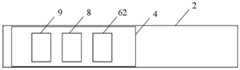
- the photographing apparatusincludes: a camera 1 and a connecting rod 2, the connecting rod 2 is connected to the camera 1 , and the connecting rod 2 is provided with a first An opening 3; as shown in FIG.
- the photographing devicefurther includes a circuit board 4, a connecting line 5, and an external communication interface; wherein the circuit board 4 is disposed in the connecting rod 2, the circuit board 4 is provided with a shooting button 7 through which the shooting key 7 is exposed, which is arranged to control the camera 1 to be photographed by the circuit board 4; the connecting line 5 is disposed on the connecting rod 2, Electrically connecting the camera 1 and the circuit board 4; the external communication interface is electrically connected to the circuit board 4, and is configured to obtain image data captured by the camera 1 through the circuit board 4 and to obtain the image data
- the deviceis transmitted to an external device; as shown in FIG. 3, the camera device further includes a power source 8 that is configured to supply power to the camera device.
- the userWhen photographing is performed using the above-described photographing device, the user is connected to an external device through an external communication interface, and image data captured by the camera 1 can be displayed on an external device, and the user can press the first opening 3 on the connecting rod 2 to shoot.
- the key 7, the circuit board 4acquires a control signal, and the control signal is transmitted to the camera 1 through the connecting line 5, so that the camera 1 is controlled to shoot by the shooting button 7; the user can also press the shooting button on the external device, and the external device will
- the acquisition control signalis transmitted to the circuit board 4 through the external communication interface, and the control signal is transmitted to the camera 1 through the connection line 5, thereby controlling the camera 1 to perform shooting by the capture key of the external device.
- the external devicemay be a smart mobile terminal such as a smart phone, and may also be a portable terminal such as a portable digital device (PAD), a tablet computer, or a laptop computer.
- a smart mobile terminalsuch as a smart phone
- a portable terminalsuch as a portable digital device (PAD), a tablet computer, or a laptop computer.
- PADportable digital device
- the photographing button 7may be set to start photographing when the button is short pressed, and the camera starts to photograph when the button is pressed. During the imaging process, if the shooting button 7 is pressed again, the camera stops imaging.
- the photographing apparatusfurther includes a memory 9 that obtains image data captured by the camera 1 through the circuit board 4 and stores the image data; the external communication interface The memory 9 is connected to be arranged to transmit image data stored in the memory 9 to an external device.
- the external communication interfaceincludes a Universal Serial Bus (USB) interface 61 and/or a wireless communication interface 62 configured to communicate with an external device.
- USBUniversal Serial Bus
- the wireless communication interface 62may be a Wireless Fidelity (WIFI) interface, a Bluetooth interface, an infrared interface, or other wireless communication interface, which is not limited in the embodiment of the present invention.
- WIFIWireless Fidelity
- the image data stored in the memory 9can be transmitted to the external device through the external communication interface, and on the other hand, the image data captured by the camera 1 can be synchronously displayed on the external device through the external communication interface. The user can clearly observe the image data captured by the camera 1 through the external device, thereby improving the user experience.
- the external communication interfaceincludes a USB interface 61, and the USB interface 61 can be set to charge the power source 8.
- the connecting rod 2is further provided with a second opening 10 .
- the circuit board 4is further provided with an opening key 11 of the wireless communication interface 62 .
- the open key 11 of the wireless communication interface 62is exposed through the second opening 10; the open key 11 of the wireless communication interface 62 controls the wireless communication interface 62 to turn on or off the wireless function through the circuit board 4.
- the connecting rod 2is further provided with a third opening 12, as shown in FIG. 2, the circuit board 4 is further provided with the power button. 13.
- the power button 13is exposed through the third opening 12; the power button 13 controls the camera to be turned on or off through the circuit board 4.
- the connecting rods 2may be disposed in a pen shape.
- the connecting rods 2may be disposed in other shapes as needed, which is not limited in the embodiment of the present invention.
- the connecting rod 2is a telescopic connecting rod. In this way, the user can adjust the length of the connecting rod 2 as needed to perform long-distance shooting.
- the telescopic connecting rodis an N-stage connecting rod and the N-th connecting rod can be pushed into the N-1th connecting rod, and the N is an integer greater than 1.
- the circuit board 4is disposed in the first stage connecting rod, and the Nth stage connecting rod is connected to the camera 1.
- the circuit board 4occupies only a small part of the space of the first stage connecting rod.
- the telescopic connecting rodis a three-stage connecting rod, and the second-stage connecting rod can be completely pushed into the first-stage connecting rod, and the third-stage connecting The rod can be completely pushed into the second-stage connecting rod, and the camera 1 is located outside the telescopic connecting rod.
- the camera 1can also be disposed in the telescopic connecting rod, which is implemented in the present invention. There are no restrictions in the examples.
- the usercan adjust the telescopic connecting rod to a specified length to meet the shooting needs as needed.
- the connecting line 5is also elongated to a specified length as the telescopic connecting rod is elongated.
- FIG. 2when the telescopic connecting rod is fully stretched, the connecting line 5 is also elongated to the longest length with the full extension of the telescopic connecting rod; as shown in FIG.
- the connecting line 5When the telescopic connecting rod is fully retracted, the connecting line 5 also contracts, and the connecting line 5 is located in the telescopic connecting rod.
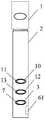
- the connecting rod 2includes a telescopic connecting rod 21 and a fixing rod 22, wherein the fixing rod 22 is connected to the telescopic connection by a rotatable connecting device 14.
- the rod 21; the telescopic connecting rod 21is connected to the camera 1; as shown in FIG. 8, the circuit board 4 is disposed in the fixing rod 22.
- the telescopic connecting rod 21can be adjusted to a specified length as needed, as shown in FIG. 8, when the telescopic connecting rod 21 is fully stretched, the connecting line 5 also follows The full extension of the telescopic connecting rod is elongated to the longest length; as shown in Fig. 9, when the telescopic connecting rod is fully retracted, the connecting line 5 also contracts, and the connecting line 5 is located at the Said in the telescopic connecting rod.
- the vertical position and/or the left and right direction of the camera 1are adjusted by adjusting the rotatable connecting device 14, and after the shooting is completed, as shown in FIG.
- the telescopic connecting rod 21can be fully retracted and the rotatable connecting device 14 can be reset. In this way, when the user shoots in a small space such as under a special scene such as a table, under the bed, under the sofa, etc., the telescopic connecting rod 21 can be adjusted to a desired length and then placed in a small space.
- the rotatable connecting device 14is not placed in the narrow space, and the user can adjust the shooting angle of the camera 1 through the rotatable connecting device 14, thereby obtaining a satisfactory photo or video, so that the user can experience better. Shooting function.
- the connecting rod 2can be connected to the camera 1 through the rotatable connecting device 14, which is not limited in the embodiment of the invention.
- the connecting wire 5is folded and arranged in the connecting rod 2.
- the camera 1can be electrically connected to the circuit board 4 through a connector 15.
- the connector 15is an FPC connector.
- FPCFlexible Printed Circuit
- the power source 8, the memory 9 and the wireless communication interface 62can be mounted on one side of the circuit board 4, as shown in FIG. 4, the shooting key 7, the power key 13, and the wireless communication interface 62.
- the switch key 11, the USB interface 61, and the connector 15can be mounted on the other side of the circuit board 4.
- the resistance devicein order to avoid damage of the connecting line 5 folded in the connecting rod 2, reduce the space occupied by the connecting line 5, and reduce the connection between the connecting line 5 and the connecting rod 2
- the resistance deviceas shown in FIG. 11, further includes: a wire rotating shaft 16; the wire rotating shaft 16 is disposed to receive the connecting wire 5.
- the pull shaft 16may be disposed in the fixing rod 22; when the connecting rod 2 is When the N-stage connecting rod is connected, the cable rotating shaft 16 may be disposed in the first-stage connecting rod.
- the pull shaft 16is disposed to be surrounded by the connecting line 5; when photographing is performed using the connecting rod 2, as shown in FIG.
- the connecting line 5 wound around the pull shaft 16is stretched.
- the connecting wire 5occupies little space of the inner space of the connecting rod 2, and does not generate resistance with the connecting rod 2, affecting the connecting rod Stretch of 2.
- the cable rotating shaft 16includes: a rotating shaft body 161 and a brush 162; wherein:
- the rotating shaft body 161includes a first side and a second side, the first side is provided with a first contact piece, and the second side is provided with a second contact piece, the first contact piece is electrically connected to the a second contact piece and the connecting wire 5; the brush 162 is located on the second side, and is disposed to electrically connect the second contact piece and the circuit board 4.
- the pull wire shaft 16may be electrically connected to the circuit board 4 through a connector 15.
- the connecting line 5is an FPC connecting line
- the connector 15is an FPC connector
- the pull shaft 16is an FPC pull shaft.
- the FPC pull shaftis a micro FPC pull shaft.
- the metal wires at one end of the FPC cableare electrically connected to the FPC cable in the order of arrangement.
- Each of the metal contacts of the first contact piece outside the shaft body 161 of the shaft, each metal contact of the first contact piecesequentially communicates with each metal contact of the second contact piece inside the shaft body 161,
- One end of the brush 162 of the FPC pull shaftis electrically connected to each metal contact of the second contact piece in turn, and the other end of the wire is led out through the central axis of the rotating shaft of the rotating shaft body 161 and electrically connected to the FPC connector, the FPC connection
- the deviceis electrically connected to the circuit board 4.
- the power button 13can be pressed to turn on the power source 8, and the power source 8 supplies power to the camera 1, the memory 9 and the wireless communication interface 62, and presses the switch key 11 of the wireless communication interface 62 through the wireless communication interface 62.
- the external devicecan synchronously display the photo or video taken by the camera 1, adjust the length of the connecting rod as needed, and adjust the shooting angle of the camera 1 through the rotatable connection device 14, press the shooting button 7 or external
- the photographing button of the devicecan be photographed or photographed, and the photograph or video obtained by photographing or photographing can be saved in the memory 9, and the photo or video can be exported to other external devices through the USB interface 61 or the wireless communication interface 62 as needed.
- the usercan also press the power button 13, turn on the power source 8, and enable the power source 8 to supply power to the camera 1 and the memory 9. Adjust the length of the connecting rod as needed and adjust the shooting angle of the camera 1 through the rotatable connecting device 14, and press the shooting.
- the key 7can be photographed or photographed, and the photograph or video obtained by photographing or photographing can be saved in the memory 9.
- the usercan export the photo or video to other external devices through the USB interface 61 or the wireless communication interface 62. View photos or videos taken by camera 1 from an external device. The user can turn off the power button 13 when the user does not need to use the camera.
- an embodiment of the present inventionfurther provides a photographing system including the photographing apparatus and an external device, and the external device includes a display.
- the photographing deviceis configured to transmit image data captured by the camera 1 to the external device through the external communication interface.
- the external deviceis arranged to display the image data on the display.
- the userWhen shooting using the above shooting system, the user is connected to an external device through an external communication interface, and image data captured by the camera 1 of the camera device can be displayed on an external device, and the user can
- the circuit board 4acquires a control signal by pressing the photographing key 7 of the first opening 3 on the connecting rod 2, and the control signal is transmitted to the camera 1 through the connecting line 5, thereby controlling the camera 1 by the photographing key 7.
- the usercan also press the shooting button on the external device, and the external device transmits the acquisition control signal to the circuit board 4 through the external communication interface, and the control signal is transmitted to the camera 1 through the connection line 5, thereby passing the shooting button of the external device.
- the camera 1is controlled to perform shooting.
- the external devicemay be a smart mobile terminal such as a smart phone, and may also be a portable terminal such as a PAD, a tablet computer, or a laptop computer.
- a smart mobile terminalsuch as a smart phone
- a portable terminalsuch as a PAD, a tablet computer, or a laptop computer.
- the external communication interfaceincludes a USB interface 61 and/or a wireless communication interface 62 arranged to communicate with an external device.
- the wireless communication interface 62may be a WIFI interface, a Bluetooth interface, an infrared interface, or other wireless communication interface, which is not limited in the embodiment of the present invention.
- the image data stored in the memory 9can be transmitted to the external device through the external communication interface, and on the other hand, the image data captured by the camera 1 can be synchronously displayed on the external device through the external communication interface. The user can clearly observe the image data captured by the camera 1 through the external device, thereby improving the user experience.
- the usercan connect with an external device through the external communication interface, and the image data captured by the camera can be displayed on the external device, and the user can press the shooting button.
- the camerais controlled to shoot.
- the photographing deviceis relatively small in size and convenient to carry; the camera of the photographing device is connected with the connecting rod, and when shooting, the photographing button on the connecting rod can be pressed to realize shooting without the need of the camera and the connecting rod.
- the assemblyis simple, and the operation is simple.
- the userafter establishing a connection with the external device through the external communication interface, the user can clearly see the view screen on the external device and then take a picture, thereby improving the user experience.
Landscapes
- Engineering & Computer Science (AREA)
- Multimedia (AREA)
- Signal Processing (AREA)
- Studio Devices (AREA)
Abstract
Description
Translated fromChinese本申请涉及但不限于电子设备领域,尤其涉及一种拍摄装置及拍摄系统。The present application relates to, but is not limited to, the field of electronic devices, and in particular, to a photographing device and a photographing system.
目前,相机、移动终端如智能手机、平板电脑等被广泛的应用于多种场合,记录着人们生活中的点滴。At present, cameras and mobile terminals such as smart phones and tablet computers are widely used in many occasions to record the bits and pieces of people's lives.
用户在使用相机或者移动终端进行拍摄时,通常会遇到一些特殊情况,在这些特殊情况下,用户无法方便的使用相机或者移动终端拍摄到满意的照片或者视频,影响用户体验。例如,使用相机或者移动终端的用户希望在特殊场景如狭小的空间内取景,然而,由于相机或者移动终端自身的体积限制,无法伸入到狭小的空间内,因此,用户无法拍摄到狭小空间内的景物。再例如,用户自拍时,特别是多人同时用一部相机或者移动终端进行自拍时,手持相机或者移动终端的用户需要高举双手,将相机或者移动终端放置在距离自拍用户较远的位置上进行拍摄,然而,相机或者移动终端距离自拍用户的距离非常有限,只能进行近距离拍摄,而不能进行远距离拍摄。目前,人们通常使用自拍杆来协助自拍,然而,使用自拍杆进行拍摄存在以下的不足:When a user uses a camera or a mobile terminal to shoot, there are usually some special cases. In these special cases, the user cannot conveniently use the camera or the mobile terminal to take a satisfactory photo or video, which affects the user experience. For example, a user who uses a camera or a mobile terminal wishes to view a scene in a special scene such as a small space. However, due to the size limitation of the camera or the mobile terminal itself, it is impossible to extend into a small space, and therefore, the user cannot capture a small space. Scenery. For another example, when the user takes a self-portrait, especially when multiple people use a camera or a mobile terminal to take a self-portrait at the same time, the user of the handheld camera or the mobile terminal needs to raise his hands and place the camera or the mobile terminal at a position far away from the self-timer user. Shooting, however, the camera or mobile terminal is very limited in distance from the self-timer, and can only be shot at close range, but not at long distances. Currently, people usually use a selfie stick to assist with self-portraits. However, there are the following disadvantages when using the selfie stick:
(1)用户在使用时首先需要将相机或者移动终端固定在自拍杆一端的固定夹上,通过自拍杆上的USB数据线或者蓝牙与相机或者移动终端建立连接后,通过按压设置在自拍杆另一端上的遥控按钮进行拍摄,操作比较复杂。(1) The user first needs to fix the camera or mobile terminal to the fixed clip at one end of the self-timer lever, and establish a connection with the camera or the mobile terminal through the USB data cable or Bluetooth on the selfie stick, and then set the self-timer by pressing the button. The remote control button on one end is used for shooting, and the operation is complicated.
(2)多数自拍杆在折叠之后仍比较长,并且固定相机或者移动终端的固定架占用空间比较大,不方便随身携带。(2) Most self-timer levers are still relatively long after folding, and the fixed frame of the fixed camera or mobile terminal takes up a large space and is not convenient to carry around.
(3)当自拍杆被拉伸到最长长度时,用户很难看清楚相机或者移动终端显示屏上的取景画面,影响用户体验。(3) When the selfie stick is stretched to the longest length, it is difficult for the user to see the viewfinder screen on the display of the camera or the mobile terminal, which affects the user experience.
发明内容Summary of the invention
以下是对本文详细描述的主题的概述。本概述并非是为了限制权利要求的保护范围。The following is an overview of the topics detailed in this document. This Summary is not intended to limit the scope of the claims.
本发明实施例提供了一种拍摄装置及拍摄系统,可以达到携带方便、操作简单以及提高用户体验的目的。The embodiment of the invention provides a photographing device and a photographing system, which can achieve convenient carrying and operationSimple and improve the user experience.
一种拍摄装置,所述拍摄装置包括:A photographing device, the photographing device comprising:
摄像头;camera;
连接杆,连接所述摄像头,所述连接杆上设置有第一开孔;Connecting a rod, connecting the camera, the connecting rod is provided with a first opening;
电路板,设置在所述连接杆内;a circuit board disposed in the connecting rod;
连接线,设置在所述连接杆内,电连接所述摄像头和所述电路板;a connecting wire disposed in the connecting rod to electrically connect the camera and the circuit board;
外部通信接口,电连接所述电路板,设置为通过所述电路板获得所述摄像头拍摄的图像数据并将所述图像数据传输给外部设备;An external communication interface electrically connecting the circuit board, configured to obtain image data captured by the camera through the circuit board and transmit the image data to an external device;
电源,设置为为所述拍摄装置供电;a power source configured to supply power to the camera device;
其中,所述电路板上设置有拍摄键,所述拍摄键通过所述第一开孔显露,设置为通过所述电路板控制所述摄像头进行拍摄。The shooting board is provided with a shooting button, and the shooting key is exposed through the first opening, and is configured to control the camera to perform shooting through the circuit board.
可选地,所述外部通信接口包括通用串行总线USB接口和/或无线通信接口。Optionally, the external communication interface comprises a universal serial bus USB interface and/or a wireless communication interface.
可选地,所述连接杆上还设置有第二开孔,所述电路板上还设置有所述无线通信接口的开关键,所述无线通信接口的开关键通过所述第二开孔显露;Optionally, the connecting rod is further provided with a second opening, and the circuit board is further provided with an opening key of the wireless communication interface, and an opening key of the wireless communication interface is exposed through the second opening ;
其中,所述无线通信接口的开关键通过所述电路板控制所述无线通信接口开启或者关闭无线功能。The switch key of the wireless communication interface controls the wireless communication interface to enable or disable the wireless function through the circuit board.
可选地,所述拍摄装置还包括存储器,所述存储器通过所述电路板获得所述摄像头拍摄的图像数据并存储所述图像数据;Optionally, the photographing device further includes a memory, the memory obtains image data captured by the camera through the circuit board and stores the image data;
所述外部通信接口,连接所述存储器,设置为将所述存储器中存储的图像数据传输给外部设备。The external communication interface is connected to the memory and configured to transmit image data stored in the memory to an external device.
可选地,所述连接杆为可伸缩连接杆。Optionally, the connecting rod is a telescopic connecting rod.
可选地,所述连接杆包括固定杆和可伸缩连接杆,其中:Optionally, the connecting rod comprises a fixing rod and a telescopic connecting rod, wherein:
所述固定杆通过可旋转连接装置连接所述可伸缩连接杆;所述可伸缩连接杆连接所述摄像头。The fixing rod is connected to the telescopic connecting rod through a rotatable connecting device; the telescopic connecting rod is connected to the camera.
可选地,所述连接线折叠排布在所述连接杆内。Optionally, the connecting line is folded and arranged in the connecting rod.
可选地,所述拍摄装置还包括拉线转轴;所述拉线转轴设置为收容所述连接线。Optionally, the photographing device further includes a cable rotating shaft; the wire rotating shaft is configured to receive the connecting wire.
可选地,所述拉线转轴包括:转轴本体和电刷,其中,Optionally, the pull wire shaft includes: a rotating shaft body and a brush, wherein
所述转轴本体,包括第一侧和第二侧,所述第一侧上设置有第一接触片,所述第二侧上设置有第二接触片,所述第一接触片电连接所述第二接触片与所述连接线;The shaft body includes a first side and a second side, the first side is provided with a first contact piece, and the second side is provided with a second contact piece, the first contact piece is electrically connected to the a second contact piece and the connecting line;
所述电刷,位于所述第二侧,设置为电连接所述第二接触片与所述电路板。The brush is located on the second side and is configured to electrically connect the second contact piece and the circuit board.
一种拍摄系统,所述拍摄系统包括上述拍摄装置和外部设备,所述外部设备包括显示器。A photographing system including the above-described photographing device and an external device, the external device including a display.
所述拍摄装置,设置为通过所述外部通信接口将所述摄像头拍摄的图像数据传输给所述外部设备;The photographing device is configured to transmit image data captured by the camera to the external device through the external communication interface;
所述外部设备,设置为在所述显示器上显示所述图像数据。The external device is arranged to display the image data on the display.
本发明实施例提供了一种拍摄装置及拍摄系统,该拍摄装置包括:摄像头、连接杆、设置在所述连接杆内的电路板、连接线、外部接口和设置为为所述拍摄装置供电的电源;其中,所述连接杆连接所述摄像头,所述连接杆上设置有第一开孔;所述连接线设置在所述连接杆内,电连接所述摄像头和所述电路板;所述外部通信接口电连接所述电路板,设置为通过所述电路板获得所述摄像头拍摄的图像数据并将所述图像数据传输给外部设备;所述电路板上设置有拍摄键,所述拍摄键通过所述第一开孔显露,设置为通过所述电路板控制所述摄像头进行拍摄。在使用所述拍摄装置进行拍摄时,用户可以通过所述外部通信接口与外部设备连接,摄像头拍摄的图像数据就可以显示在外部设备上,用户可以通过按压所述拍摄键来控制所述摄像头进行拍摄。该拍摄装置体积比较小,携带方便;所述拍摄装置的摄像头与连接杆连接,拍摄时,只需按压所述连接杆上的拍照键即可以实现拍摄,而不需要将所述摄像头与连接杆进行装配,操作简单;除此以外,在通过外部通信接口与外部设备建立连接之后,用户可以在所述外部设备上清楚的看到取景画面后再进行拍摄,提高了用户体验。Embodiments of the present invention provide a photographing apparatus and a photographing system, including: a camera, a connecting rod, a circuit board disposed in the connecting rod, a connecting line, an external interface, and a power supply configured to supply the photographing device a power supply; wherein the connecting rod is connected to the camera, the connecting rod is provided with a first opening; the connecting line is disposed in the connecting rod, electrically connecting the camera and the circuit board; The external communication interface is electrically connected to the circuit board, and is configured to obtain image data captured by the camera through the circuit board and transmit the image data to an external device; the circuit board is provided with a shooting button, the shooting button Exposed by the first opening, it is arranged to control the camera to perform shooting through the circuit board. When the photographing device is used for photographing, the user can connect with an external device through the external communication interface, and the image data captured by the camera can be displayed on the external device, and the user can control the camera by pressing the shooting button. Shooting. The photographing device is relatively small in size and convenient to carry; the camera of the photographing device is connected with the connecting rod, and when shooting, the photographing button on the connecting rod can be pressed to realize shooting without the need of the camera and the connecting rod. The assembly is simple, and the operation is simple. In addition, after establishing a connection with the external device through the external communication interface, the user can clearly see the view screen on the external device and then take a picture, thereby improving the user experience.
附图概述BRIEF abstract
图1为本发明实施例1提供的一种拍摄装置在使用时的前视图;1 is a front view of a photographing apparatus according to
图2为本发明实施例1提供的一种拍摄装置在使用时的侧视剖视图;2 is a side cross-sectional view of a photographing apparatus according to
图3为本发明实施例1提供的一种拍摄装置中电路板一侧的结构图;3 is a structural diagram of a circuit board side in an image pickup apparatus according to
图4为本发明实施例1提供的一种拍摄装置中电路板另一侧的结构图;4 is a structural diagram of the other side of a circuit board in an image pickup apparatus according to
图5为本发明实施例1提供的一种拍摄装置在未使用时的前视图;FIG. 5 is a front elevational view of a photographing apparatus according to
图6为本发明实施例1提供的一种拍摄装置在未使用时的侧视剖视图;6 is a side cross-sectional view of a photographing apparatus according to
图7为本发明实施例1提供的另一种拍摄装置在使用时的前视图;FIG. 7 is a front view of another imaging device according to
图8为本发明实施例1提供的另一种拍摄装置在使用时的侧视剖视图;Figure 8 is a side cross-sectional view showing another imaging device according to
图9为本发明实施例1提供的另一种拍摄装置在未使用时的侧视剖视图;Figure 9 is a side cross-sectional view showing another imaging device according to
图10为本发明实施例1提供的另一种拍摄装置在未使用时的前视图;FIG. 10 is a front elevational view of another imaging apparatus according to
图11为本发明实施例1提供的具有拉线转轴的另一种拍摄装置在未使用时的侧视剖视图;Figure 11 is a side cross-sectional view showing another imaging device having a cable rotating shaft according to
图12为本发明实施例1提供的具有拉线转轴的另一种拍摄装置在使用时的侧视剖视图;Figure 12 is a side cross-sectional view showing another imaging device having a cable rotating shaft according to
图13为本发明实施例1提供的拉线转轴的结构图。Figure 13 is a structural view showing a cable rotating shaft according to
下文中将结合附图对本发明的实施例进行详细说明。需要说明的是,在不冲突的情况下,本申请中的实施例及实施例中的特征可以相互组合。Embodiments of the present invention will be described in detail below with reference to the accompanying drawings. It should be noted that the embodiments in the present application and the features in the embodiments may be combined with each other without conflict.
实施例1Example 1
本发明实施例提供了一种拍摄装置,如图1所示,所述拍摄装置包括:摄像头1和连接杆2,所述连接杆2连接所述摄像头1,所述连接杆2上设置有第一开孔3;结合如图2所示,所述拍摄装置还包括电路板4、连接线5、外部通信接口;其中,所述电路板4设置在所述连接杆2内,所述电路板4上设置有拍摄键7,所述拍摄键7通过所述第一开孔显露3,设置为通过所述电路板4控制所述摄像头1进行拍摄;所述连接线5设置在所述连接杆2内,电连接所述摄像头1和所述电路板4;所述外部通信接口,电连接所述电路板4,设置为通过所述电路板4获得所述摄像头1拍摄的图像数据并将所述图像数据传输给外部设备;如图3所示,所述拍摄装置还包括电源8,所述电源8设置为为所述拍摄装置供电。An embodiment of the present invention provides a photographing apparatus. As shown in FIG. 1 , the photographing apparatus includes: a
在使用上述拍摄装置进行拍摄时,用户通过外部通信接口与外部设备连接,摄像头1拍摄的图像数据就可以在外部设备上显示,用户可以按压穿过连接杆2上的第一开孔3的拍摄键7,电路板4获取控制信号,所述控制信号通过连接线5传递给摄像头1,从而通过拍摄键7控制所述摄像头1进行拍摄;用户也可以按压外部设备上的拍摄键,外部设备将获取控制信号通过外部通信接口传递给电路板4,所述控制信号通过连接线5再传递给摄像头1,从而通过外部设备的拍摄键控制所述摄像头1进行拍摄。When photographing is performed using the above-described photographing device, the user is connected to an external device through an external communication interface, and image data captured by the
可选地,所述外部设备可以为智能手机这种智能移动终端,还可以为如个人数字助理(Portable Android Device,PAD)、平板电脑、手提电脑这种便携式终端。Optionally, the external device may be a smart mobile terminal such as a smart phone, and may also be a portable terminal such as a portable digital device (PAD), a tablet computer, or a laptop computer.
可选地,为了方便用户开启所述摄像装置的拍照或者摄像功能,可以将所述拍摄键7设置为在短按时,所述拍摄装置开始拍照,在长按时,所述拍摄装置开始摄像,在摄像的过程中,如果再次按下所述拍摄键7,所述拍摄装置会停止摄像。Optionally, in order to facilitate the user to turn on the photographing or photographing function of the camera, the photographing
可选地,如图3所示,所述拍摄装置还包括存储器9,所述存储器9通过所述电路板4获得所述摄像头1拍摄的图像数据并存储所述图像数据;所述外部通信接口,连接所述存储器9,设置为将所述存储器9中存储的图像数据传输给外部设备。Optionally, as shown in FIG. 3, the photographing apparatus further includes a memory 9 that obtains image data captured by the
可选地,如图3和图4所示,所述外部通信接口包括通用串行总线(Universal Serial Bus,USB)接口61和/或无线通信接口62,设置为与外部设备进行通信。Optionally, as shown in FIGS. 3 and 4, the external communication interface includes a Universal Serial Bus (USB)
其中,所述无线通信接口62可以为无线保真(Wireless Fidelity,WIFI)接口、蓝牙接口、红外接口或者其他无线通信接口,本发明实施例中不做限定。The
一方面,通过所述外部通信接口可以将所述存储器9中存储的图像数据传输给外部设备,另一方面,通过所述外部通信接口可以使外部设备上同步显示所述摄像头1拍摄的图像数据,用户通过所述外部设备可以清楚的观察到所述摄像头1拍摄的图像数据,从而提高用户体验。On the one hand, the image data stored in the memory 9 can be transmitted to the external device through the external communication interface, and on the other hand, the image data captured by the
这里需要说明的是,当所述电源8为可充电电源8时,所述外部通信接口包括USB接口61,USB接口61可设置为给所述电源8充电。It should be noted here that when the
可选地,如图1所示,所述连接杆2上还设置有第二开孔10,如图2所示,所述电路板4上还设置有所述无线通信接口62的开关键11,所述无线通信接口62的开关键11通过所述第二开孔10显露;所述无线通信接口62的开关键11通过所述电路板4控制所述无线通信接口62开启或者关闭无线功能。Optionally, as shown in FIG. 1 , the connecting
可选地,为了节约电源8电量,如图1所示,所述连接杆2上还设置有第三开孔12,如图2所示,所述电路板4上还设置有所述电源键13,所述电源键13通过所述第三开孔12显露;所述电源键13通过所述电路板4控制所述拍摄装置开启或者关闭。Optionally, in order to save the power of the
可选地,为了方便携带,所述连接杆2可设置为笔形,当然,所述连接杆2也可根据需要设置为其他形状,在本发明实施例中不作限定。For example, the connecting
在本发明的其他实施例中,如图1所示,所述连接杆2为可伸缩连接杆。这样,用户可以根据需要调整连接杆2的长度进行远距离拍摄。In other embodiments of the invention, as shown in Figure 1, the connecting
可选地,所述可伸缩连接杆为N级连接杆并且第N级连接杆可推入第N-1级连接杆内,所述N为大于1的整数。如图2所示,所述电路板4设置在第一级连接杆内,第N级连接杆连接所述摄像头1,所述电路板4只占用所述第一级连接杆的很小一部分空间。示例的,如图1和5所示,所述可伸缩连接杆为三级连接杆,所述第二级连接杆可完全被推入所述第一级连接杆中,所述第三级连接杆可完全被推入所述第二级连接杆中,所述摄像头1位于所述可伸缩连接杆外,当然,所述摄像头1也可设置位于所述可伸缩连接杆内,在本发明实施例中不作限定。Optionally, the telescopic connecting rod is an N-stage connecting rod and the N-th connecting rod can be pushed into the N-1th connecting rod, and the N is an integer greater than 1. As shown in FIG. 2, the
用户可以根据需要调节所述可伸缩连接杆到指定长度以满足拍摄需求,在所述可伸缩连接杆被拉伸时,所述连接线5也随所述可伸缩连接杆的拉长被拉长到指定的长度。如图2所示,所述可伸缩连接杆被完全拉伸时,所述连接线5也随所述可伸缩连接杆的完全拉伸被拉长到最长长度;如图6所示,所述可伸缩连接杆被完全收回时,所述连接线5也随之收缩,所述连接线5位于所述可伸缩连接杆内。The user can adjust the telescopic connecting rod to a specified length to meet the shooting needs as needed.When the telescopic connecting rod is stretched, the connecting
在本发明的其他实施例中,如图7所示,所述连接杆2包括可伸缩连接杆21和固定杆22,其中,所述固定杆22通过可旋转连接装置14连接所述可伸缩连接杆21;所述可伸缩连接杆21连接所述摄像头1;如图8所示,所述电路板4设置在所述固定杆22内。In other embodiments of the present invention, as shown in FIG. 7, the connecting
用户在拍摄时,可以根据需要将所述可伸缩连接杆21到调节的指定长度,如图8所示,所述可伸缩连接杆21被完全拉伸时,所述连接线5也随所述可伸缩连接杆的完全拉伸被拉长到最长长度;如图9所示,所述可伸缩连接杆被完全收回时,所述连接线5也随之收缩,所述连接线5位于所述可伸缩连接杆内。用户将所述可伸缩连接杆21调节到指定长度后,通过调整所述可旋转连接装置14将所述摄像头1上下位置和/或左右方向进行调整,用户在拍摄完成后,如图10所示,可以将所述可伸缩连接杆21完全收回,再将所述可旋转连接装置14复位。这样,用户在特殊场景例如桌子下、床下、沙发下面等狭小的空间中进行拍摄时,就可以将所述可伸缩连接杆21调节到所需长度,再放入到狭小的空间中,而所述可旋转连接装置14未放入所述狭小空间内,用户可以通过所述可旋转连接装置14来调节所述摄像头1的拍摄角度,从而获得满意的照片或者视频,使用户可以体验到更好的拍摄功能。When the user shoots, the telescopic connecting
当然,所述连接杆2可以通过所述可旋转连接装置14连接所述摄像头1,本发明实施例中不做限定。Of course, the connecting
可选地,如图6和图9所示,所述连接线5折叠排布在所述连接杆2内。Alternatively, as shown in FIGS. 6 and 9, the connecting
在本发明的其他实施例中,如图2和图8所示,所述摄像头1可通过连接器15电连接所述电路板4。In other embodiments of the present invention, as shown in FIGS. 2 and 8, the
可选地,当所述连接线5为柔性电路板4(Flexible Printed Circuit,FPC)连接线时,所述连接器15为FPC连接器。Optionally, when the connecting
在实际应用中,如图3所示,电源8、存储器9和无线通信接口62可安装在电路板4的一面上,如图4所述,拍摄键7、电源键13、无线通信接口62的开关键11、USB接口61以及连接器15可以安装在电路板4的另一面上。In practical applications, as shown in FIG. 3, the
在本发明的其他实施例中,为了避免折叠在所述连接杆2内的连接线5损坏、减小所述连接线5占用空间以及减小所述连接线5与所述连接杆2之间的阻力,如图11所示,所述拍摄装置还包括:拉线转轴16;所述拉线转轴16设置为收容所述连接线5。In other embodiments of the present invention, in order to avoid damage of the connecting
可选地,当所述连接杆2包括可伸缩连接杆21和固定杆22时,如图11所示,所述拉线转轴16可以设置在所述固定杆22内;当所述连接杆2为N级连接杆时,所述拉线转轴16可以设置在所述第一级连接杆内。Optionally, when the connecting
如图11所示,在未使用所述连接杆2进行拍摄时,所述拉线转轴16设置为被所述连接线5环绕;在使用所述连接杆2进行拍摄时,如图12所示,环绕在所述拉线转轴16上的所述连接线5被拉伸。不论使用所述拍摄装置或者未使用所述拍摄装置,所述连接线5很少占用所述连接杆2的内部空间,也不会与所述连接杆2之间产生阻力,影响所述连接杆2的拉伸。As shown in FIG. 11, when the connecting
可选地,如图13所示,所述拉线转轴16包括:转轴本体161和电刷162;其中:Optionally, as shown in FIG. 13, the
所述转轴本体161包括第一侧和第二侧,所述第一侧上设置有第一接触片,所述第二侧上设置有第二接触片,所述第一接触片电连接所述第二接触片与所述连接线5;所述电刷162位于所述第二侧,设置为电连接所述第二接触片与所述电路板4。The
可选地,如图11和图12所示,所述拉线转轴16可通过连接器15电连接所述电路板4。Alternatively, as shown in FIGS. 11 and 12, the
可选地,当所述连接线5为FPC连接线时,所述连接器15为FPC连接器,所述拉线转轴16为FPC拉线转轴,示例的,所述FPC拉线转轴为微型FPC拉线转轴。Optionally, when the connecting
可选地,FPC连接线一端的金属导线按排列顺序依次电连接FPC拉线转轴的转轴本体161外侧的第一接触片的各个金属触点,所述第一接触片的每个金属触点与转轴本体161内侧的第二接触片的每个金属触点依次连通,所述FPC拉线转轴的电刷162的一端依次电连接所述第二接触片的各个金属触点,另一端的导线经转轴本体161的转轴中心轴引出并电连接所述FPC连接器,所述FPC连接器电连接所述电路板4。Optionally, the metal wires at one end of the FPC cable are electrically connected to the FPC cable in the order of arrangement.Each of the metal contacts of the first contact piece outside the
用户在使用拍摄装置进行拍摄时,可以按压电源键13,开启电源8,使电源8给摄像头1、存储器9和无线通信接口62供电,按压无线通信接口62的开关键11,通过无线通信接口62与外部设备无线连接,这样,外部设备可以同步显示摄像头1拍摄的照片或者视频,根据需要调整所述连接杆的长度并通过可旋转连接装置14调节摄像头1的拍摄角度,按压拍摄键7或者外部设备的拍摄键就可以进行拍照或者摄像,拍照或者摄像获得的照片或者视频可以保存在存储器9内,需要时可以通过USB接口61或者无线通信接口62将照片或者视频导出到其他外部设备。When the user performs shooting using the photographing device, the
当然,用户也可以按压电源键13,开启电源8,使电源8给摄像头1和存储器9供电,根据需要调整所述连接杆的长度并通过可旋转连接装置14调节摄像头1的拍摄角度,按压拍摄键7就可以进行拍照或者摄像,拍照或者摄像获得的照片或者视频可以保存在存储器9内,在拍摄完成后,用户可以通过USB接口61或者无线通信接口62将照片或者视频导出到其他外部设备,通过外部设备再查看摄像头1拍摄的照片或者视频。用户在不需要使用拍摄装置时,用户可以将电源键13关闭。Of course, the user can also press the
实施例2Example 2
在实施例1的基础上,本发明实施例还提供了一种拍摄系统,所述拍摄系统包括所述的拍摄装置和外部设备,所述外部设备包括显示器。On the basis of
所述拍摄装置,设置为通过所述外部通信接口将所述摄像头1拍摄的图像数据传输给所述外部设备。The photographing device is configured to transmit image data captured by the
所述外部设备,设置为在所述显示器上显示所述图像数据。The external device is arranged to display the image data on the display.
在使用上述拍摄系统进行拍摄时,用户通过外部通信接口与外部设备连接,摄像装置的摄像头1拍摄的图像数据就可以在外部设备上显示,用户可以按压穿过连接杆2上的第一开孔3的拍摄键7,电路板4获取控制信号,所述控制信号通过连接线5传递给摄像头1,从而通过拍摄键7控制所述摄像头1进行拍摄;用户也可以按压外部设备上的拍摄键,外部设备将获取控制信号通过外部通信接口传递给电路板4,所述控制信号通过连接线5再传递给摄像头1,从而通过外部设备的拍摄键控制所述摄像头1进行拍摄。When shooting using the above shooting system, the user is connected to an external device through an external communication interface, and image data captured by the
可选地,所述外部设备可以为智能手机这种智能移动终端,还可以为如PAD、平板电脑、手提电脑这种便携式终端。Optionally, the external device may be a smart mobile terminal such as a smart phone, and may also be a portable terminal such as a PAD, a tablet computer, or a laptop computer.
可选地,如图3和图4所示,所述外部通信接口包括USB接口61和/或无线通信接口62,设置为与外部设备进行通信。Optionally, as shown in Figures 3 and 4, the external communication interface includes a
其中,所述无线通信接口62可以为WIFI接口、蓝牙接口、红外接口或者其他无线通信接口,本发明实施例中不做限定。The
一方面,通过所述外部通信接口可以将所述存储器9中存储的图像数据传输给外部设备,另一方面,通过所述外部通信接口可以使外部设备上同步显示所述摄像头1拍摄的图像数据,用户通过所述外部设备可以清楚的观察所述摄像头1拍摄的图像数据,从而提高用户体验。On the one hand, the image data stored in the memory 9 can be transmitted to the external device through the external communication interface, and on the other hand, the image data captured by the
以上所述,仅为本发明可选实施例而已,并非用于限定本发明实施例的保护范围。The above is only an alternative embodiment of the present invention, and is not intended to limit the scope of protection of the embodiments of the present invention.
在通过本发明实施例的所述拍摄装置进行拍摄时,用户可以通过所述外部通信接口与外部设备连接,摄像头拍摄的图像数据就可以显示在外部设备上,用户可以通过按压所述拍摄键来控制所述摄像头进行拍摄。该拍摄装置体积比较小,携带方便;所述拍摄装置的摄像头与连接杆连接,拍摄时,只需按压所述连接杆上的拍照键即可以实现拍摄,而不需要将所述摄像头与连接杆进行装配,操作简单;除此以外,在通过外部通信接口与外部设备建立连接之后,用户可以在所述外部设备上清楚的看到取景画面后再进行拍摄,提高了用户体验。When the photographing apparatus of the embodiment of the present invention performs photographing, the user can connect with an external device through the external communication interface, and the image data captured by the camera can be displayed on the external device, and the user can press the shooting button. The camera is controlled to shoot. The photographing device is relatively small in size and convenient to carry; the camera of the photographing device is connected with the connecting rod, and when shooting, the photographing button on the connecting rod can be pressed to realize shooting without the need of the camera and the connecting rod. The assembly is simple, and the operation is simple. In addition, after establishing a connection with the external device through the external communication interface, the user can clearly see the view screen on the external device and then take a picture, thereby improving the user experience.
Claims (10)
Translated fromChineseApplications Claiming Priority (2)
| Application Number | Priority Date | Filing Date | Title |
|---|---|---|---|
| CN201610232253.0ACN107302648A (en) | 2016-04-14 | 2016-04-14 | A kind of filming apparatus and camera system |
| CN201610232253.0 | 2016-04-14 |
Publications (1)
| Publication Number | Publication Date |
|---|---|
| WO2017177568A1true WO2017177568A1 (en) | 2017-10-19 |
Family
ID=60041294
Family Applications (1)
| Application Number | Title | Priority Date | Filing Date |
|---|---|---|---|
| PCT/CN2016/090010CeasedWO2017177568A1 (en) | 2016-04-14 | 2016-07-14 | Photographing apparatus and photographing system |
Country Status (2)
| Country | Link |
|---|---|
| CN (1) | CN107302648A (en) |
| WO (1) | WO2017177568A1 (en) |
Families Citing this family (1)
| Publication number | Priority date | Publication date | Assignee | Title |
|---|---|---|---|---|
| CN109495627A (en)* | 2019-01-21 | 2019-03-19 | 深圳市趣创科技有限公司 | A kind of self-shooting bar |
Citations (7)
| Publication number | Priority date | Publication date | Assignee | Title |
|---|---|---|---|---|
| CN101621616A (en)* | 2009-07-30 | 2010-01-06 | 浙江大立科技股份有限公司 | Infrared image pickup device with any visual angle surveillance and detection functions |
| US20100277578A1 (en)* | 2009-04-30 | 2010-11-04 | David Mitchell | Inspection camera |
| CN102626301A (en)* | 2012-04-28 | 2012-08-08 | 无锡市第二人民医院 | Multifunctional portable wireless medical endoscope |
| CN203314929U (en)* | 2013-06-28 | 2013-12-04 | 江苏金视光电科技有限公司 | Wireless superfine electronic endoscope |
| CN203658657U (en)* | 2013-11-01 | 2014-06-18 | 深圳市永恒丰智能设备有限公司 | Endoscope movably plugged on mobile device and endoscope system thereof |
| CN103984086A (en)* | 2014-04-18 | 2014-08-13 | 深圳市永恒丰智能设备有限公司 | Endoscope capable of being connected with mobile device and endoscope system |
| CN204362166U (en)* | 2015-01-10 | 2015-05-27 | 广州南北电子科技有限公司 | A kind of picture pick-up device and shadowless lamp |
Family Cites Families (3)
| Publication number | Priority date | Publication date | Assignee | Title |
|---|---|---|---|---|
| CN203618025U (en)* | 2013-10-23 | 2014-05-28 | 李正良 | External shooting lens device applied to handset |
| CN204119346U (en)* | 2014-10-15 | 2015-01-21 | 叶宏洋 | Self-timer |
| CN104935700A (en)* | 2015-06-29 | 2015-09-23 | 深圳市九洲电器有限公司 | Mobile terminal |
- 2016
- 2016-04-14CNCN201610232253.0Apatent/CN107302648A/ennot_activeWithdrawn
- 2016-07-14WOPCT/CN2016/090010patent/WO2017177568A1/ennot_activeCeased
Patent Citations (7)
| Publication number | Priority date | Publication date | Assignee | Title |
|---|---|---|---|---|
| US20100277578A1 (en)* | 2009-04-30 | 2010-11-04 | David Mitchell | Inspection camera |
| CN101621616A (en)* | 2009-07-30 | 2010-01-06 | 浙江大立科技股份有限公司 | Infrared image pickup device with any visual angle surveillance and detection functions |
| CN102626301A (en)* | 2012-04-28 | 2012-08-08 | 无锡市第二人民医院 | Multifunctional portable wireless medical endoscope |
| CN203314929U (en)* | 2013-06-28 | 2013-12-04 | 江苏金视光电科技有限公司 | Wireless superfine electronic endoscope |
| CN203658657U (en)* | 2013-11-01 | 2014-06-18 | 深圳市永恒丰智能设备有限公司 | Endoscope movably plugged on mobile device and endoscope system thereof |
| CN103984086A (en)* | 2014-04-18 | 2014-08-13 | 深圳市永恒丰智能设备有限公司 | Endoscope capable of being connected with mobile device and endoscope system |
| CN204362166U (en)* | 2015-01-10 | 2015-05-27 | 广州南北电子科技有限公司 | A kind of picture pick-up device and shadowless lamp |
Also Published As
| Publication number | Publication date |
|---|---|
| CN107302648A (en) | 2017-10-27 |
Similar Documents
| Publication | Publication Date | Title |
|---|---|---|
| CN105049686B (en) | Double-camera mobile terminal | |
| US10084897B2 (en) | Electronic device housing with removable camera | |
| US20160006920A1 (en) | System for mobile device with detachable camera and method of use thereof | |
| CN204119346U (en) | Self-timer | |
| TWM546639U (en) | Panorama image capture apparatus | |
| TW201320631A (en) | Mobile Device with side-mounted camera module | |
| KR101718441B1 (en) | Self taking picture bar | |
| CN105379243A (en) | Portable camera dock | |
| KR20140000986U (en) | A Bluetooth Remote-Control Photographing Device | |
| CN114390199A (en) | Shooting method and electronic equipment | |
| CN106412443A (en) | Shooting method and mobile terminal | |
| WO2016187947A1 (en) | Remote photographing method, master control photographing terminal, controlled photographing terminal and photographing system | |
| CN103442107A (en) | Mobile phone | |
| TWI446089B (en) | Lens docking station | |
| CN105554390A (en) | A camera method and device, selfie stick, camera system and mobile terminal | |
| US20250071413A1 (en) | Imaging device, imaging instruction method, and imaging instruction program | |
| WO2017177568A1 (en) | Photographing apparatus and photographing system | |
| KR20140010805A (en) | Photographing system and control method thereof | |
| CN105516608A (en) | Selfie stick, shooting device adapted to the selfie stick and method for taking images thereof | |
| CN105611137A (en) | Portable digital image shooting apparatus | |
| KR101633865B1 (en) | Self Camera Photographing Device For Smart-phone | |
| CN103581436B (en) | Mobile phone is utilized to control the method for single anti-panoramic photography | |
| CN105939459A (en) | Display device and image display method | |
| CN203120024U (en) | Camera shooting device for mobile terminal | |
| CN206191229U (en) | selfie stick |
Legal Events
| Date | Code | Title | Description |
|---|---|---|---|
| NENP | Non-entry into the national phase | Ref country code:DE | |
| 121 | Ep: the epo has been informed by wipo that ep was designated in this application | Ref document number:16898383 Country of ref document:EP Kind code of ref document:A1 | |
| 122 | Ep: pct application non-entry in european phase | Ref document number:16898383 Country of ref document:EP Kind code of ref document:A1 |