WO2017170634A1 - Seal member, syringe assembly, and prefilled syringe - Google Patents
Seal member, syringe assembly, and prefilled syringeDownload PDFInfo
- Publication number
- WO2017170634A1 WO2017170634A1PCT/JP2017/012794JP2017012794WWO2017170634A1WO 2017170634 A1WO2017170634 A1WO 2017170634A1JP 2017012794 WJP2017012794 WJP 2017012794WWO 2017170634 A1WO2017170634 A1WO 2017170634A1
- Authority
- WO
- WIPO (PCT)
- Prior art keywords
- seal member
- syringe
- main body
- cylindrical body
- gasket
- Prior art date
- Legal status (The legal status is an assumption and is not a legal conclusion. Google has not performed a legal analysis and makes no representation as to the accuracy of the status listed.)
- Ceased
Links
Images


Classifications
- A—HUMAN NECESSITIES
- A61—MEDICAL OR VETERINARY SCIENCE; HYGIENE
- A61M—DEVICES FOR INTRODUCING MEDIA INTO, OR ONTO, THE BODY; DEVICES FOR TRANSDUCING BODY MEDIA OR FOR TAKING MEDIA FROM THE BODY; DEVICES FOR PRODUCING OR ENDING SLEEP OR STUPOR
- A61M5/00—Devices for bringing media into the body in a subcutaneous, intra-vascular or intramuscular way; Accessories therefor, e.g. filling or cleaning devices, arm-rests
- A61M5/178—Syringes
- A61M5/28—Syringe ampoules or carpules, i.e. ampoules or carpules provided with a needle
- A61M5/285—Syringe ampoules or carpules, i.e. ampoules or carpules provided with a needle with sealing means to be broken or opened
- A61M5/286—Syringe ampoules or carpules, i.e. ampoules or carpules provided with a needle with sealing means to be broken or opened upon internal pressure increase, e.g. pierced or burst
- A—HUMAN NECESSITIES
- A61—MEDICAL OR VETERINARY SCIENCE; HYGIENE
- A61M—DEVICES FOR INTRODUCING MEDIA INTO, OR ONTO, THE BODY; DEVICES FOR TRANSDUCING BODY MEDIA OR FOR TAKING MEDIA FROM THE BODY; DEVICES FOR PRODUCING OR ENDING SLEEP OR STUPOR
- A61M5/00—Devices for bringing media into the body in a subcutaneous, intra-vascular or intramuscular way; Accessories therefor, e.g. filling or cleaning devices, arm-rests
- A61M5/178—Syringes
- A61M5/31—Details
- A61M5/3129—Syringe barrels
- A61M5/3134—Syringe barrels characterised by constructional features of the distal end, i.e. end closest to the tip of the needle cannula
- A—HUMAN NECESSITIES
- A61—MEDICAL OR VETERINARY SCIENCE; HYGIENE
- A61M—DEVICES FOR INTRODUCING MEDIA INTO, OR ONTO, THE BODY; DEVICES FOR TRANSDUCING BODY MEDIA OR FOR TAKING MEDIA FROM THE BODY; DEVICES FOR PRODUCING OR ENDING SLEEP OR STUPOR
- A61M5/00—Devices for bringing media into the body in a subcutaneous, intra-vascular or intramuscular way; Accessories therefor, e.g. filling or cleaning devices, arm-rests
- A61M5/178—Syringes
- A61M5/31—Details
- A61M5/315—Pistons; Piston-rods; Guiding, blocking or restricting the movement of the rod or piston; Appliances on the rod for facilitating dosing ; Dosing mechanisms
- A61M5/31511—Piston or piston-rod constructions, e.g. connection of piston with piston-rod
- A61M5/31513—Piston constructions to improve sealing or sliding
- A—HUMAN NECESSITIES
- A61—MEDICAL OR VETERINARY SCIENCE; HYGIENE
- A61M—DEVICES FOR INTRODUCING MEDIA INTO, OR ONTO, THE BODY; DEVICES FOR TRANSDUCING BODY MEDIA OR FOR TAKING MEDIA FROM THE BODY; DEVICES FOR PRODUCING OR ENDING SLEEP OR STUPOR
- A61M5/00—Devices for bringing media into the body in a subcutaneous, intra-vascular or intramuscular way; Accessories therefor, e.g. filling or cleaning devices, arm-rests
- A61M5/178—Syringes
- A61M5/31—Details
- A61M5/32—Needles; Details of needles pertaining to their connection with syringe or hub; Accessories for bringing the needle into, or holding the needle on, the body; Devices for protection of needles
- A61M5/3286—Needle tip design, e.g. for improved penetration
- A—HUMAN NECESSITIES
- A61—MEDICAL OR VETERINARY SCIENCE; HYGIENE
- A61M—DEVICES FOR INTRODUCING MEDIA INTO, OR ONTO, THE BODY; DEVICES FOR TRANSDUCING BODY MEDIA OR FOR TAKING MEDIA FROM THE BODY; DEVICES FOR PRODUCING OR ENDING SLEEP OR STUPOR
- A61M5/00—Devices for bringing media into the body in a subcutaneous, intra-vascular or intramuscular way; Accessories therefor, e.g. filling or cleaning devices, arm-rests
- A61M5/178—Syringes
- A61M5/31—Details
- A61M2005/3103—Leak prevention means for distal end of syringes, i.e. syringe end for mounting a needle
- A61M2005/3106—Plugs for syringes without needle
- A—HUMAN NECESSITIES
- A61—MEDICAL OR VETERINARY SCIENCE; HYGIENE
- A61M—DEVICES FOR INTRODUCING MEDIA INTO, OR ONTO, THE BODY; DEVICES FOR TRANSDUCING BODY MEDIA OR FOR TAKING MEDIA FROM THE BODY; DEVICES FOR PRODUCING OR ENDING SLEEP OR STUPOR
- A61M5/00—Devices for bringing media into the body in a subcutaneous, intra-vascular or intramuscular way; Accessories therefor, e.g. filling or cleaning devices, arm-rests
- A61M5/178—Syringes
- A61M5/31—Details
- A61M5/3129—Syringe barrels
- A61M2005/3131—Syringe barrels specially adapted for improving sealing or sliding
- A—HUMAN NECESSITIES
- A61—MEDICAL OR VETERINARY SCIENCE; HYGIENE
- A61M—DEVICES FOR INTRODUCING MEDIA INTO, OR ONTO, THE BODY; DEVICES FOR TRANSDUCING BODY MEDIA OR FOR TAKING MEDIA FROM THE BODY; DEVICES FOR PRODUCING OR ENDING SLEEP OR STUPOR
- A61M5/00—Devices for bringing media into the body in a subcutaneous, intra-vascular or intramuscular way; Accessories therefor, e.g. filling or cleaning devices, arm-rests
- A61M5/178—Syringes
- A61M5/31—Details
- A61M5/315—Pistons; Piston-rods; Guiding, blocking or restricting the movement of the rod or piston; Appliances on the rod for facilitating dosing ; Dosing mechanisms
- A61M5/31596—Pistons; Piston-rods; Guiding, blocking or restricting the movement of the rod or piston; Appliances on the rod for facilitating dosing ; Dosing mechanisms comprising means for injection of two or more media, e.g. by mixing
- A61M2005/31598—Pistons; Piston-rods; Guiding, blocking or restricting the movement of the rod or piston; Appliances on the rod for facilitating dosing ; Dosing mechanisms comprising means for injection of two or more media, e.g. by mixing having multiple telescopically sliding coaxial pistons encompassing volumes for components to be mixed
- A—HUMAN NECESSITIES
- A61—MEDICAL OR VETERINARY SCIENCE; HYGIENE
- A61M—DEVICES FOR INTRODUCING MEDIA INTO, OR ONTO, THE BODY; DEVICES FOR TRANSDUCING BODY MEDIA OR FOR TAKING MEDIA FROM THE BODY; DEVICES FOR PRODUCING OR ENDING SLEEP OR STUPOR
- A61M2205/00—General characteristics of the apparatus
- A61M2205/02—General characteristics of the apparatus characterised by a particular materials
- A61M2205/0216—Materials providing elastic properties, e.g. for facilitating deformation and avoid breaking
- A—HUMAN NECESSITIES
- A61—MEDICAL OR VETERINARY SCIENCE; HYGIENE
- A61M—DEVICES FOR INTRODUCING MEDIA INTO, OR ONTO, THE BODY; DEVICES FOR TRANSDUCING BODY MEDIA OR FOR TAKING MEDIA FROM THE BODY; DEVICES FOR PRODUCING OR ENDING SLEEP OR STUPOR
- A61M2205/00—General characteristics of the apparatus
- A61M2205/02—General characteristics of the apparatus characterised by a particular materials
- A61M2205/0222—Materials for reducing friction
- A—HUMAN NECESSITIES
- A61—MEDICAL OR VETERINARY SCIENCE; HYGIENE
- A61M—DEVICES FOR INTRODUCING MEDIA INTO, OR ONTO, THE BODY; DEVICES FOR TRANSDUCING BODY MEDIA OR FOR TAKING MEDIA FROM THE BODY; DEVICES FOR PRODUCING OR ENDING SLEEP OR STUPOR
- A61M2205/00—General characteristics of the apparatus
- A61M2205/02—General characteristics of the apparatus characterised by a particular materials
- A61M2205/0238—General characteristics of the apparatus characterised by a particular materials the material being a coating or protective layer
- A—HUMAN NECESSITIES
- A61—MEDICAL OR VETERINARY SCIENCE; HYGIENE
- A61M—DEVICES FOR INTRODUCING MEDIA INTO, OR ONTO, THE BODY; DEVICES FOR TRANSDUCING BODY MEDIA OR FOR TAKING MEDIA FROM THE BODY; DEVICES FOR PRODUCING OR ENDING SLEEP OR STUPOR
- A61M5/00—Devices for bringing media into the body in a subcutaneous, intra-vascular or intramuscular way; Accessories therefor, e.g. filling or cleaning devices, arm-rests
- A61M5/178—Syringes
- A61M5/28—Syringe ampoules or carpules, i.e. ampoules or carpules provided with a needle
- A61M5/284—Syringe ampoules or carpules, i.e. ampoules or carpules provided with a needle comprising means for injection of two or more media, e.g. by mixing
Definitions
- the present inventionrelates to a seal assembly that includes a syringe that can store a chemical solution in advance, and a seal member that seals the chemical solution in a liquid-tight manner in the syringe, and a syringe assembly and a prefilled syringe that include the seal member.
- Patent Document 1there is a technique described in Patent Document 1, for example, in order to prevent the chemical liquid from leaking from the syringe before the chemical liquid is administered.
- Patent Document 1describes a technique in which a slit is provided in a stopper for sealing a chemical solution.
- An object of the present inventionis to provide a seal member, a syringe assembly, and a prefilled syringe that can prevent the chemical liquid from leaking out of the syringe before administering the chemical liquid in consideration of the above problems. .
- the seal member of the present inventionfor achieving the above object is a seal member that is used in a syringe assembly including a syringe having a cylindrical body that can be filled with a chemical solution, and is disposed in the cylindrical body.
- the seal memberincludes a cylindrical main body portion, a closed end portion, and a cleavage portion.
- the main bodyhas an opening formed at the proximal end and a close contact portion capable of forming a liquid-tight seal between the inner wall of the cylinder.
- the closed end portionis formed continuously and integrally with the main body portion at the front end of the main body portion, and seals the front end of the main body portion.
- the cleaving partis formed at the closed end part and communicates with the opening part.
- the main body portionis arranged in the cylinder together with the gasket that can slide in the cylinder, and is located on the tip side in the cylinder relative to the gasket, thereby forming a chemical solution storage space for storing the chemical solution together with the gasket and the cylinder. . Furthermore, when a predetermined pressure is applied to the storage space, the cleaving portion is cleaved and a liquid passing port communicating with the opening is formed at the closed end portion.
- the syringe assembly of the present inventionincludes the above-described sealing member and a syringe. And the sealing member is arrange
- the prefilled syringe of the present inventionincludes the above-described syringe assembly, a gasket, and a chemical solution.
- the gasketis slidably disposed in a syringe having a cylindrical body filled with a chemical solution and in a cylindrical hole of the cylindrical body.
- the chemical liquidis stored in a chemical liquid storage space formed by a seal member, a gasket, and a cylindrical body.
- the chemical solutioncan be sealed in the syringe.
- FIG. 1is a perspective view showing a prefilled syringe.
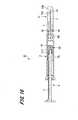
- FIG. 2is a cross-sectional view showing a prefilled syringe.
- the prefilled syringe 1 of this examplea chemical solution M1 to be administered to a living body is stored in advance.
- the prefilled syringe 1includes a syringe 2 that stores the chemical M1, a needle tube 3 that is fixed to the syringe 2, a pusher 4, a cap 5, and a seal member 20. ing.
- the syringe 2includes a cylinder 6 that is filled with the chemical solution M1 and a fixing portion 7 that is continuous with the cylinder 6.
- the cylinder 6is formed in a substantially cylindrical shape.
- a fixing portion 7is continuously formed on the distal end side of the cylindrical body 6.
- the base end side of the cylinder 6is opening.
- the cylindrical hole 6a of the cylindrical body 6is filled with the chemical solution M1, and a gasket 12 of the pusher 4 described later is inserted from the proximal end side of the cylindrical body 6.
- a proximal end portion 3b of the needle tube 3 fixed to the fixing portion 7protrudes from an inner front end surface 6b of the distal end portion of the cylindrical hole 6a in the cylindrical body 6, and the needle tube 3 and the cylindrical hole 6a communicate with each other.
- a seal member 20is disposed on the inner front end surface 6b of the cylindrical hole 6a.
- the shape of the cylinder 6may be a hollow square column shape or a hexagonal column shape.
- the fixing part 7which shows an example of a holding part protrudes along the axial direction from the front end side of the cylinder 6.
- the fixing part 7is formed in a substantially cylindrical shape. Further, the intermediate portion in the axial direction of the fixed portion 7 is formed so that the outer diameter thereof is smaller than the outer diameter of both end portions in the axial direction. Therefore, the fixed part 7 has a shape with a narrowed middle part.
- the needle tube 3is fixed to the fixing portion 7 by a fixing method such as insert molding or adhesion with an adhesive.
- Examples of the material of the syringe 2 having the above-described structureinclude polyvinyl chloride, polyethylene, polypropylene, cyclic polyolefin, polystyrene, poly- (4-methylpentene-1), polycarbonate, acrylic resin, and acrylonitrile-butadiene-styrene.
- Examples thereofinclude various resins such as polymers, polyesters such as polyethylene terephthalate, butadiene-styrene copolymers, and polyamides (for example, nylon 6, nylon 6,6, nylon 6,10, nylon 12).
- a resinsuch as polypropylene, cyclic polyolefin, polyester, or poly- (4-methylpentene-1).
- the material of the syringe 2is substantially transparent in order to ensure internal visibility.
- the drug filled in the syringe 2may be any drug that is normally used as an injection.
- protein drugssuch as antibodies, peptide drugs such as hormones, nucleic acid drugs, cell drugs, blood products, various drugs Vaccines to prevent infectious diseases, anticancer agents, anesthetics, narcotics, antibiotics, steroids, proteolytic enzyme inhibitors, sugar injection solutions such as heparin and glucose, and electrolyte correction injections such as sodium chloride and potassium lactate Liquids, vitamins, fat emulsions, contrast agents, stimulants and the like.
- protein drugssuch as antibodies, peptide drugs such as hormones, nucleic acid drugs, cell drugs, blood products, various drugs Vaccines to prevent infectious diseases, anticancer agents, anesthetics, narcotics, antibiotics, steroids, proteolytic enzyme inhibitors, sugar injection solutions such as heparin and glucose, and electrolyte correction injections such as sodium chloride and potassium lactate Liquids, vitamins, fat emulsion
- the needle tube 3uses a standard of ISO medical needle tube (ISO9626: 1991 / Amd.1: 2001 (E)) having a size of 10 to 33 gauge (outer diameter: ⁇ 3.5 to 0.2 mm), A 16 to 33 gauge (outer diameter: ⁇ 1.7 to 0.2 mm) is preferably used.
- a blade surface for making the needle tip 3a an acute angleis formed at the tip of the needle tube 3. The needle tip 3a at the tip of the needle tube 3 is punctured into the living body.
- the material of the needle tube 3examples include stainless steel, but are not limited thereto, and aluminum, aluminum alloy, titanium, titanium alloy, and other metals can be used.
- the needle tube 3can be not only a straight needle but also a tapered needle having at least a part tapered.
- the proximal end portionhas a larger diameter than the end portion of the needle tip 3a, and the intermediate portion may have a taper structure.
- the cross-sectional shape of the needle tube 3may be not only a circle but also a polygon such as a triangle.
- a coating agentmade of, for example, a silicone resin or a fluorine resin is applied to the surface of the needle tube 3 on the needle tip 3a side.
- the needle tube 3is fixed to the syringe 2 with the needle tip 3a protruding outward.
- the needle tip 3 a at the tip of the needle tube 3protrudes from the tip of the fixing portion 7 of the syringe 2.
- the proximal end portion 3 b which is the proximal end side of the needle tube 3is exposed from the inner distal end surface 6 b of the cylindrical body 6 in the syringe 2 toward the cylindrical hole 6 a.
- the needle hole 3 and the cylinder hole 6a of the cylinder 6 of the syringe 2are connected.
- the pusher 4has a push rod 11 and a gasket 12.
- the push bar 11is formed in a bar shape and is pressed by a user.
- the tip of the push rod 11is inserted into the tube hole 6 a of the tube body 6.
- the length of the push rod 11 in the axial directionis set to be approximately the same as or longer than the length in which the gasket 12 can be slid along the cylindrical hole 6 a of the cylindrical body 6.
- a connecting portion 11 ais formed at the tip of the push rod 11.
- the connection part 11ait is the external thread part formed in the front-end
- the connecting portion 11ais inserted into the connected portion 12a in the gasket 12 and screwed with the connected portion 12a.
- the gasket 12is slidably disposed in the cylindrical hole 6 a of the cylindrical body 6.
- the gasket 12is formed in a substantially cylindrical shape, and is in liquid-tight contact with the wall surface of the cylindrical hole 6 a of the cylindrical body 6. And the gasket 12 has divided the inside of the cylinder hole 6a of the cylinder 6 into two.
- a space on the inner tip surface 6b side of the gasket 12 in the cylindrical hole 6ais a liquid chamber filled with the chemical liquid M1.
- the gasket 12has a distal end closed and a proximal end opened.
- a connected portion 12 ais formed at the proximal end of the gasket 12.
- the front end portion 12 b of the gasket 12is formed in a substantially truncated cone shape in accordance with the shape of the inner front end surface 6 b of the cylindrical body 6.
- the connected portion 12ais, for example, a female screw portion.
- the connected portion 12ais screwed with the connecting portion 11a of the push rod 11, the push rod 11 and the gasket 12 are connected.
- the push rod 11is pressed by the user, the gasket 12 slides and moves in the cylindrical hole 6 a of the cylindrical body 6, and the chemical solution M1 filled in the cylindrical hole 6 a is supplied to the proximal end portion of the needle tube 3. Push towards 3b.
- the material of the gasket 12is not particularly limited, but is preferably made of an elastic material in order to improve the liquid tightness with the cylinder 6.
- the elastic materialinclude various rubber materials such as natural rubber, isobutylene rubber, and silicone rubber, various thermoplastic elastomers such as olefin and styrene, and mixtures thereof.
- the cap 5is formed in a substantially cylindrical shape, and has a proximal end opened and a distal end closed.
- the cap 5is made of an elastic member such as rubber or elastomer.
- the cap 5is attached to the distal end side of the syringe 2 so as to cover the needle tip 3 a of the needle tube 3 and the fixing portion 7 of the syringe 2. Then, the needle tip 3 a side of the needle tube 3 and the fixing portion 7 are inserted into the cylindrical hole 5 a of the cap 5.
- the inner diameter of the base end portion in the cylindrical hole 5a of the cap 5is set to be approximately equal to or slightly smaller than the outer diameter of the intermediate portion of the fixed portion 7. Therefore, when the cap 5 is attached to the syringe 2, the outer peripheral surface of the intermediate portion of the fixing portion 7 is in close contact with the inner peripheral surface of the cap 5. Thereby, the needle tip 3 a side of the needle tube 3, which is the distal end side from the intermediate portion of the fixing portion 7, is sealed by the intermediate portion and the inner peripheral surface of the cap 5. As a result, it is possible to prevent bacteria from adhering to the portion protruding from the fixed portion 7 of the needle tube 3 including the needle tip 3a toward the distal end side.
- the cap 5should just have the inner peripheral surface of the cap 5 closely_contact
- the inner peripheral surface of the cap 5tightens the constricted portion that is an intermediate portion of the fixed portion 7 by its elastic force. Thereby, the inner peripheral surface of the cap 5 and the constricted portion of the fixing portion 7 are engaged, and the cap 5 can be prevented from being detached from the syringe 2 during transport.
- the needle tip 3 a of the needle tube 3is not punctured into the cap 5. As a result, coring does not occur in the needle tube 3, and the needle tip 3a of the needle tube 3 is not damaged.
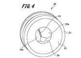
- FIGS. 3 and 4are perspective views showing the seal member 20
- FIGS. 5 and 6are cross-sectional views showing the seal member 20.
- the seal member 20has a main body portion 21 and a closed end portion 22.
- the main body portion 21is formed in a substantially cylindrical shape. Further, the main body 21 is positioned on the distal end side in the cylindrical body 6 with respect to the gasket 12 when being disposed in the cylindrical body 6. And the chemical
- the distal end surface of the closed end portion 22is formed in a substantially truncated cone shape in a complementary manner to the shape of the inner distal end surface 6 b of the cylindrical body 6 in the syringe 2.
- the main body portion 21has a distal end side rib portion 21 a that is a close contact portion and a proximal end side rib portion 21 b.
- the distal end side rib portion 21 a and the proximal end side rib portion 21 bare ring-shaped convex portions formed on the outer peripheral surface of the main body portion 21.
- the distal end side rib portion 21a and the proximal end side rib portion 21bprotrude from the outer peripheral surface of the main body portion 21 toward the outer side in the radial direction.
- the distal end rib portion 21 ais formed on the distal end side of the main body portion 21, and the proximal end rib portion 21 b is formed on the proximal end side of the main body portion 21. Further, a predetermined interval is formed between the distal end side rib portion 21a and the proximal end side rib portion 21b. Furthermore, the front end rib portion 21 a is adjacent to the inner front end surface 6 b of the cylindrical body 6.
- the distal end side rib portion 21 a and the proximal end side rib portion 21 bare in liquid tight contact with the wall surface of the cylindrical hole 6 a of the cylindrical body 6. Therefore, the distal end side rib portion 21 a and the proximal end side rib portion 21 b form a liquid-tight seal with the inner wall of the cylindrical body 6.
- the chemical liquid M1 filled in the chemical liquid storage space formed between the seal member 20 and the gasket 12is sealed in a liquid-tight manner, and the chemical liquid M1 is removed from the seal member 20 and the needle tube 3 before the chemical liquid is administered. Leakage can be prevented.
- the main body portion 21with the two ribs of the distal end side rib portion 21a and the proximal end side rib portion 21b, it is possible to reliably prevent the chemical liquid M1 from leaking from the seal member 20.
- distal end side rib portion 21 a and the proximal end side rib portion 21 bare slidably in contact with the wall surface of the cylindrical hole 6 a of the cylindrical body 6.
- a separation portion 21cis formed between the distal end side rib portion 21a and the proximal end side rib portion 21b.
- the separation portion 21 cis a concave portion that is recessed from the outer peripheral surface of the main body portion 21 in a ring shape.
- an opening 23is formed on the base end side of the main body 21.
- the opening 23opens in a substantially frustoconical shape that is complementary to the shape of the tip 12 b of the gasket 12.
- a pressing portion 24is formed continuously at the distal end side of the opening 23.
- a cleaving portion 25 provided at the closed end portion 22is continuous with the tip of the pressing portion 24.
- the pressing part 24has two pressing surfaces 24a and 24a. As shown in FIG. 5, the two pressing surfaces 24 a and 24 a are formed in a tapered shape so that the distance between the two pressing surfaces 24 a and 24 a is continuously narrowed as approaching the closed end portion 22 and the cleavage portion 25. Yes. Therefore, the pressing portion 24 is formed as a tapered concave portion. And in the closed end part 22, the cleaving part 25 is formed in succession to the two pressing surfaces 24a and 24a.
- the cleavage part 25is linearly formed in a direction perpendicular to the axial center of the main body part 21 and the closed end part 22, that is, a direction perpendicular to the axial direction of the cylinder 6.
- the cleavage part 25communicates with the opening part 23 formed in the main body part 21. Further, the vicinity of the cleavage portion 25 in the closed end portion 22 is formed to be thinner than other portions.
- the cleaving portion 25has a straight portion 25b extending from the pressing portion 24 along the axial direction of the seal member 20, and two pressed surfaces 25a and 25a.
- the pressurized surface 25ais formed continuously at the tip of the straight portion 25b.
- the two pressurized surfaces 25a and 25aare formed in a tapered shape so that the distance between the two pressurized surfaces 25a and 25a becomes narrower toward the tip of the closed end portion 22 away from the linear portion 25b.
- the cleavage part 25is formed as a taper-shaped recessed part which a flow path narrows continuously toward the front-end
- the material of the seal member 20is not particularly limited, but is preferably made of an elastic material in order to improve the liquid tightness with the cylindrical body 6.
- the elastic materialinclude various rubber materials such as natural rubber, isobutylene rubber, and silicone rubber, various thermoplastic elastomers such as olefin and styrene, and mixtures thereof.
- a syringe assemblyis constituted by the syringe 2 and the seal member 20 before filling with the chemical solution M1.
- the needle tip 3a of the needle tube 3is not punctured by the cap 5 or other members in a state before the drug solution is administered. Therefore, coring does not occur in the needle tube 3, and the needle tip 3a of the needle tube 3 is not damaged.
- the seal member 20applies pressure from the chemical solution M1 pushed out by the gasket 12, as shown in FIG. receive. Therefore, force is applied to the two pressing surfaces 24a and 24a of the pressing portion 24 in a direction away from each other by the pressure from the chemical liquid M1. Furthermore, as shown in FIG. 8, force is applied to the two pressed surfaces 25a and 25a of the cleaving portion 25 in directions away from each other.
- the chemical solution M1by receiving the pressure from the chemical solution M1 on two opposite surfaces such as the two pressing surfaces 24a and 24a of the pressing portion 24 and the two pressed surfaces 25a and 25a of the cleaving portion 25, the chemical solution The pressure from M1 can be concentrated. Further, by providing the straight portion 25b between the two pressing surfaces 24a, 24a and the two pressurized surfaces 25a, 25a, the chemical solution is directed from the pressing portion 24 toward the two pressurized surfaces 25a, 25a of the cleavage portion 25. The pressure from M1 can be concentrated more.
- a ring-shaped separation portion 21 cis formed on the outer peripheral surface of the main body portion 21 near the pressing portion 24.
- the separation portion 21cmakes it easy for the seal member 20 to be elastically deformed by the pressure from the chemical solution M1, and the two pressing surfaces 24a and 24a of the pressing portion 24 are easily spread away from each other.
- the front end of the cleavage portion 25is cleaved as shown in FIG. And in the location in which the cleaving part 25 in the closed end part 22 of the sealing member 20 was provided, the liquid communication port T1 which can communicate with the opening part 23 and the chemical liquid M1 can be formed is formed.
- the cylindrical hole 6a of the cylindrical body 6 and the needle tube 3communicate with each other via the opening 23 of the seal member 20 and the liquid passing port T1, and the drug solution M1 is discharged from the needle tube 3 and administered to the living body.
- the opening 23 of the seal member 20is formed in a substantially truncated cone shape that is complementary to the shape of the tip 12 b of the gasket 12.
- a front end rib portion 21 ais provided in the vicinity of the closed end portion 22 in the main body portion 21, and the front end rib portion 21 a is adjacent to the inner front end surface 6 b of the cylindrical body 6. Accordingly, when the chemical solution M1 is discharged, the chemical solution M1 enters between the distal end side rib portion 21a and the proximal end side rib portion 21b from the gap between the inner distal end surface 6b and the closed end portion 22 of the seal member 20. Can be prevented.
- the closed end portion 22 of the seal member 20is formed in a substantially truncated cone shape in a complementary manner to the shape of the inner front end surface 6 b of the cylindrical body 6 in the syringe 2. For this reason, when the chemical solution M1 is discharged, the amount of the chemical solution M1 remaining between the inner front end face 6b and the closed end portion 22 of the seal member 20 can be reduced.
- the cleavage part 25 to be cleavedis formed in a straight line, and the direction to cleave is one direction.
- medical solution M1can be concentrated, and the resistance which arises when the cleavage part 25 cleaves can be made small.
- the drug solution M1is administered, the cleavage portion 25 in the closed end portion 22 of the seal member 20 can be easily cleaved, and the drug solution M1 can be easily administered.
- FIG. 14is a cross-sectional view showing a prefilled syringe.
- a prefilled syringe 41 according to the second embodiment shown in FIG. 14is obtained by storing the drug solution M1 and the powdered drug N1 in the tube hole 6a of the tube 6 of the syringe 2.
- a difference between the prefilled syringe 41 according to the second embodiment and the prefilled syringe 1 according to the first embodimentis a place where the seal member 20 is disposed. Therefore, here, the same reference numerals are given to the portions common to the prefilled syringe 1 according to the first embodiment, and the duplicated description is omitted.
- the prefilled syringe 41 shown in FIG. 14mixes the drug solution M1 and the drug N1, and administers the mixed drug solution M1 and drug N1 to the living body.
- the seal member 20is disposed in the cylindrical hole 6 a of the cylindrical body 6 in the syringe 2. Further, the seal member 20 is slidably disposed at an intermediate portion in the axial direction in the cylindrical hole 6a.
- the space formed by the seal member 20 and the gasket 12 of the pusher 4 in the cylindrical hole 6ais filled with the chemical solution M1. Further, a medicine storage space is formed by the inner wall and inner front end surface 6 b of the cylindrical body 6 and the seal portion 20. In the medicine storage space, powdery medicine N1 is stored. In a state where the chemical liquid M1 and the chemical N1 are mixed, the chemical liquid M1 is sealed in a liquid-tight manner in the cylindrical hole 6a by the seal member 20 and the gasket 12. Thereby, before mixing the liquid medicine M1 and the medicine N1, the liquid medicine M1 leaks out, and it is possible to prevent the liquid medicine M1 and the medicine N1 from being mixed against the user's intention.
- a cap 51is attached to the fixing portion 7 of the syringe 2.
- the cap 51is formed in a substantially cylindrical shape, and the proximal end side is open and the distal end side is closed. Further, a sealing portion 51b is provided on the distal end side of the cap 51 in the cylindrical hole 51a.
- FIGS. 15 to 17are sectional views showing the administration operation of the prefilled syringe.
- the userpresses the push rod 11 of the pusher 4 and slides the gasket 12 toward the inner front end face 6b.
- the pressure of the chemical solution M1is applied to the seal member 20 by the gasket 12, and the cleavage portion 25 of the seal member 20 is cleaved.
- the space in which the drug solution M1 is stored and the space in which the drug N1 is storedare communicated with each other via the liquid passing port T1 formed in the cleavage portion 25 of the seal member 20.
- the mixing operation of the drug solution M ⁇ b> 1 and the drug N ⁇ b> 1is performed in a state where the cap 51 is attached to the fixing portion 7 of the syringe 2.
- the mixing operation of the drug solution M1 and the drug N1can be performed efficiently.
- seal member 20In the embodiment described above, an example in which only one seal member 20 is provided has been described, but the present invention is not limited to this.
- a plurality of seal membersmay be arranged in a cylindrical hole of a cylindrical body in a syringe, and a plurality of different types of chemical solutions may be stored in the syringe.
- the needle tube and the syringemay be configured to be detachable from each other, and the needle tube may be attached to the syringe when the drug solution is administered.
- pressing part, 24apressing surface, 25 ... cleaving part, 25a ... pressurized surface, 25b ... straight line Part, M1 ... chemical solution, M2 ... mixture, N1 ... drug, S1 ... slit, T1 ... fluid inlet
Landscapes
- Health & Medical Sciences (AREA)
- Vascular Medicine (AREA)
- Engineering & Computer Science (AREA)
- Anesthesiology (AREA)
- Biomedical Technology (AREA)
- Heart & Thoracic Surgery (AREA)
- Hematology (AREA)
- Life Sciences & Earth Sciences (AREA)
- Animal Behavior & Ethology (AREA)
- General Health & Medical Sciences (AREA)
- Public Health (AREA)
- Veterinary Medicine (AREA)
- Infusion, Injection, And Reservoir Apparatuses (AREA)
Abstract
Description
Translated fromJapanese本発明は、予め薬液を収納可能なシリンジを備えたシリンジ組立体において、薬液をシリンジ内に液密に封止するシール部材、このシール部材を備えたシリンジ組立体及びプレフィルドシリンジに関する。The present invention relates to a seal assembly that includes a syringe that can store a chemical solution in advance, and a seal member that seals the chemical solution in a liquid-tight manner in the syringe, and a syringe assembly and a prefilled syringe that include the seal member.
近年、シリンジ内に予め薬液が充填されたプレフィルドシリンジが多く利用されるようになってきた。このようなプレフィルドシリンジでは、薬液投与時にバイアル瓶からシリンジ内に薬液を吸引する必要がなく、投与に要する時間を短縮できる。In recent years, many prefilled syringes in which a syringe is pre-filled with a chemical solution have been used. In such a prefilled syringe, it is not necessary to suck the drug solution from the vial into the syringe at the time of drug solution administration, and the time required for administration can be shortened.
例えば、特許文献1に記載された技術には、薬液を投与する前に薬液がシリンジから漏れ出ることを防ぐために、例えば、特許文献1に記載されているようなものがある。特許文献1には、薬液を封止する栓にスリットを設けた技術を記載されている。For example, in the technique described in Patent Document 1, there is a technique described in Patent Document 1, for example, in order to prevent the chemical liquid from leaking from the syringe before the chemical liquid is administered. Patent Document 1 describes a technique in which a slit is provided in a stopper for sealing a chemical solution.
しかしながら、特許文献1に記載された技術では、保管時や輸送時にスリットからシリンジに収納された薬液が漏れ出るおそれがあった。また、薬液と薬剤と混合させるプレフィルドシリンジの場合、薬液を収納する薬室から薬液が使用者の意図に反して漏れ出し、薬液と薬剤が混合される、おそれがあった。However, in the technique described in Patent Document 1, there is a possibility that the chemical solution stored in the syringe leaks from the slit during storage or transportation. Further, in the case of a prefilled syringe that is mixed with a drug solution and a drug, the drug solution leaks against the user's intention from the drug chamber in which the drug solution is stored, and the drug solution and the drug may be mixed.
本発明の目的は、上記の問題点を考慮し、薬液を投与する前にシリンジ内から薬液が漏れ出ることを防ぐことができるシール部材、シリンジ組立体及びプレフィルドシリンジを提供することを目的とする。An object of the present invention is to provide a seal member, a syringe assembly, and a prefilled syringe that can prevent the chemical liquid from leaking out of the syringe before administering the chemical liquid in consideration of the above problems. .
以上のような目的を達成するための本発明のシール部材は、薬液を充填可能な筒体を有するシリンジを備えたシリンジ組立体に用いられ、筒体内に配置されるシール部材である。また、シール部材は、筒状の本体部と、閉端部と、開裂部と、を備えている。本体部は、基端に形成された開口部と、筒体の内壁との間で液密なシールを形成可能な密着部とを有する。閉端部は、本体部の先端に本体部と連続して一体に形成され、本体部の先端を封止する。開裂部は、閉端部に形成され、開口部と連通している。また、本体部は、筒体内を摺動可能なガスケットと共に筒体内に配置され、ガスケットよりも筒体内における先端側に位置することにより、ガスケット及び筒体と共に薬液を収納する薬液収納空間を形成する。さらに、収納空間に所定の圧力が加わることにより、開裂部が開裂して閉端部に開口部と連通した通液口が形成される。The seal member of the present invention for achieving the above object is a seal member that is used in a syringe assembly including a syringe having a cylindrical body that can be filled with a chemical solution, and is disposed in the cylindrical body. The seal member includes a cylindrical main body portion, a closed end portion, and a cleavage portion. The main body has an opening formed at the proximal end and a close contact portion capable of forming a liquid-tight seal between the inner wall of the cylinder. The closed end portion is formed continuously and integrally with the main body portion at the front end of the main body portion, and seals the front end of the main body portion. The cleaving part is formed at the closed end part and communicates with the opening part. Further, the main body portion is arranged in the cylinder together with the gasket that can slide in the cylinder, and is located on the tip side in the cylinder relative to the gasket, thereby forming a chemical solution storage space for storing the chemical solution together with the gasket and the cylinder. . Furthermore, when a predetermined pressure is applied to the storage space, the cleaving portion is cleaved and a liquid passing port communicating with the opening is formed at the closed end portion.
本発明のシリンジ組立体は、上述したシール部材と、シリンジとを備えている。そして、シール部材は、筒体内に配置されている。The syringe assembly of the present invention includes the above-described sealing member and a syringe. And the sealing member is arrange | positioned in the cylinder.
また、本発明のプレフィルドシリンジは、上述したシリンジ組立体と、ガスケットと、薬液とを備えている。ガスケットは、薬液が充填された筒体を有するシリンジと、筒体の筒孔内に摺動可能に配置されている。薬液は、シール部材、ガスケット及び筒体によって形成された薬液収納空間に収納されている。Further, the prefilled syringe of the present invention includes the above-described syringe assembly, a gasket, and a chemical solution. The gasket is slidably disposed in a syringe having a cylindrical body filled with a chemical solution and in a cylindrical hole of the cylindrical body. The chemical liquid is stored in a chemical liquid storage space formed by a seal member, a gasket, and a cylindrical body.
本発明のシール部材、シリンジ組立体及びプレフィルドシリンジによれば、薬液をシリンジ内に封止することができる。According to the seal member, syringe assembly, and prefilled syringe of the present invention, the chemical solution can be sealed in the syringe.
以下、本発明のシール部材、シリンジ組立体及びプレフィルドシリンジの実施の形態例について、図1~図17を参照して説明する。なお、各図において共通の部材には、同一の符号を付している。また、本発明は、以下の形態に限定されるものではない。Hereinafter, embodiments of the seal member, syringe assembly, and prefilled syringe of the present invention will be described with reference to FIGS. In addition, the same code | symbol is attached | subjected to the common member in each figure. The present invention is not limited to the following form.
1.第1の実施の形態例
1-1.プレフィルドシリンジの構成例
まず、図1及び図2を参照して、本発明のプレフィルドシリンジの第1の実施の形態例(以下、「本例」という。)の構成例について説明する。
図1は、プレフィルドシリンジを示す斜視図である。図2は、プレフィルドシリンジを示す断面図である。1. First Embodiment 1-1. Configuration Example of Prefilled Syringe First, a configuration example of a first embodiment of the prefilled syringe of the present invention (hereinafter referred to as “this example”) will be described with reference to FIGS. 1 and 2.
FIG. 1 is a perspective view showing a prefilled syringe. FIG. 2 is a cross-sectional view showing a prefilled syringe.
本例のプレフィルドシリンジ1には、予め生体に投与する薬液M1が収納されている。図1及び図2に示すように、プレフィルドシリンジ1は、薬液M1を収納するシリンジ2と、このシリンジ2に固定された針管3と、押し子4と、キャップ5と、シール部材20とを備えている。In the prefilled syringe 1 of this example, a chemical solution M1 to be administered to a living body is stored in advance. As shown in FIGS. 1 and 2, the prefilled syringe 1 includes a
[シリンジ]
シリンジ2は、薬液M1が充填される筒体6と、この筒体6に連続する固定部7とを備えている。筒体6は、略円筒状に形成されている。筒体6の先端側に固定部7が連続して形成されている。そして、筒体6の基端側は、開口している。この筒体6の筒孔6aには、薬液M1が充填され、筒体6の基端側から後述する押し子4のガスケット12が挿入される。[Syringe]
The
また、筒体6における筒孔6aの先端部の内側先端面6bには、固定部7に固定された針管3の基端部3bが突出し、針管3と筒孔6aとが連通している。また、筒孔6aの内側先端面6bには、シール部材20が配置されている。Further, a
なお、本例では、シリンジ2の筒体6の形状を略円筒形に形成した例を説明したが、筒体6の形状は、中空の四角柱状や六角柱状であってもよい。In addition, although the example which formed the shape of the
保持部の一例を示す固定部7は、筒体6の先端側からその軸方向に沿って突出している。固定部7は、略円柱状に形成されている。また、固定部7の軸方向の中間部は、その外径が、軸方向の両端部の外径よりも小さく形成されている。そのため、固定部7は、中間部がくびれた形状となっている。この固定部7には、例えばインサート成形や、接着剤による接着等の固定方法によって針管3が固定されている。The
上述した構成を有するシリンジ2の材質としては、例えば、ポリ塩化ビニル、ポリエチレン、ポリプロピレン、環状ポリオレフィン、ポリスチレン、ポリ-(4-メチルペンテン-1)、ポリカーボネート、アクリル樹脂、アクリルニトリル-ブタジエン-スチレン共重合体、ポリエチレンテレフタレート等のポリエステル、ブタジエン-スチレン共重合体、ポリアミド(例えば、ナイロン6、ナイロン6・6、ナイロン6・10、ナイロン12)のような各種樹脂が挙げられる。その中でも、ポリプロピレン、環状ポリオレフィン、ポリエステル、ポリ-(4-メチルペンテン-1)のような樹脂を用いることが好ましい。なお、シリンジ2の材質は、内部の視認性を確保するために、実質的に透明であることが好ましい。Examples of the material of the
このシリンジ2に充填される薬剤としては、通常注射剤として使用される薬剤であれば何でもよく、例えば抗体等の蛋白質性医薬品、ホルモン等のペプチド性医薬品、核酸医薬品、細胞医薬品、血液製剤、各種感染症を予防するワクチン、抗がん剤、麻酔薬、麻薬、抗生物質、ステロイド剤、蛋白質分解酵素阻害剤、ヘパリン、ブドウ糖等の糖質注射液、塩化ナトリウムや乳酸カリウム等の電解質補正用注射液、ビタミン剤、脂肪乳剤、造影剤、覚せい剤等が挙げられる。The drug filled in the
[針管]
針管3は、ISOの医療用針管の基準(ISO9626:1991/Amd.1:2001(E))で10~33ゲージのサイズ(外径:φ3.5~0.2mm)のものを使用し、好ましくは16~33ゲージ(外径:φ1.7~0.2mm)のものを使用する。この針管3の先端には、針先3aを鋭角にするための刃面が形成されている。そして、針管3の先端の針先3aが生体に穿刺される。[Needle tube]
The
針管3の材料としては、例えば、ステンレス鋼を挙げることができるが、これに限定されるものではなく、アルミニウム、アルミニウム合金、チタン、チタン合金その他の金属を用いることができる。また、針管3は、ストレート針だけでなく、少なくとも一部がテーパー状となっているテーパー針を用いることができる。テーパー針としては、針先3a端部に比べて基端部が太い径を有しており、その中間部分をテーパー構造とすればよい。また、針管3の断面形状は、円形だけでなく、三角形等の多角形であってもよい。Examples of the material of the
更に、針管3における針先3a側の表面には、例えばシリコーン樹脂やフッ素系樹脂等からなるコーティング剤が施される。これにより、針管3を生体に穿刺した際に、皮膚と針管との摩擦を低減することができ、穿刺時に伴う痛みを軽減させることが可能となる。Furthermore, a coating agent made of, for example, a silicone resin or a fluorine resin is applied to the surface of the
この針管3は、針先3aを外側に突出させた状態でシリンジ2に固定される。そして、針管3の先端の針先3aは、シリンジ2の固定部7の先端から突出する。また、針管3の基端側である基端部3bは、シリンジ2における筒体6の内側先端面6bから筒孔6aに向けて露出している。そして、針管3とシリンジ2の筒体6の筒孔6aが連通される。The
[押し子]
次に、押し子4について説明する。
押し子4は、押し棒11と、ガスケット12とを有している。押し棒11は、棒状に形成されており、使用者によって押圧操作される。押し棒11の先端部は、筒体6の筒孔6a内に挿入される。また、押し棒11の軸方向の長さは、ガスケット12を筒体6の筒孔6a内に沿って摺動移動できる長さとほぼ同じかそれよりも長く設定されている。[Presser]
Next, the
The
押し棒11の先端部には、接続部11aが形成されている。接続部11aとしては、例えば、押し棒11の先端部に形成された雄ネジ部である。この接続部11aは、ガスケット12における被接続部12aに挿入されると共に、被接続部12aと螺合する。A connecting
ガスケット12は、筒体6の筒孔6a内に摺動可能に配置されている。ガスケット12は、略円柱状に形成されており、筒体6の筒孔6aの壁面に液密に密着している。そして、ガスケット12は、筒体6の筒孔6a内を2つに仕切っている。筒孔6a内におけるガスケット12よりも内側先端面6b側の空間は、薬液M1が充填される液室となる。The
ガスケット12は、先端が閉塞し、基端が開口している。ガスケット12の基端には、被接続部12aが形成されている。また、ガスケット12の先端部12bは、筒体6の内側先端面6bの形状に合わせて略円錐台形状に形成されている。The
被接続部12aは、例えば、雌ネジ部である。この被接続部12aが押し棒11の接続部11aと螺合することで、押し棒11とガスケット12が接続される。そして、押し棒11が使用者によって押圧されることで、ガスケット12は、筒体6の筒孔6a内を摺動移動し、筒孔6a内に充填された薬液M1を針管3の基端部3bに向けて押し出す。The
ガスケット12の材質は、特に限定されないが、筒体6との液密性を良好にするために弾性材料で構成することが好ましい。この弾性材料としては、例えば、天然ゴム、イソブチレンゴム、シリコーンゴムなどの各種ゴム材料や、オレフィン系、スチレン系等の各種熱可塑性エラストマー、あるいはそれらの混合物等を挙げることができる。The material of the
[キャップ]
キャップ5は、略円筒状に形成されており、基端が開口し、先端が閉じている。このキャップ5は、例えばゴムやエラストマー等の弾性部材から形成される。そして、図2に示すように、キャップ5は、針管3の針先3a及びシリンジ2の固定部7を覆うようにして、シリンジ2の先端側に取り付けられる。そして、キャップ5の筒孔5a内に針管3の針先3a側及び固定部7が挿入される。[cap]
The
なお、キャップ5の筒孔5aにおける基端部の内径は、固定部7の中間部の外径と略等しいか、若干小さく設定されている。そのため、キャップ5をシリンジ2に取り付けた際、固定部7における中間部の外周面がキャップ5の内周面に密着する。これにより、固定部7の中間部から先端側である針管3の針先3a側が、中間部とキャップ5の内周面によって密閉される。その結果、針先3aを含む針管3の固定部7から先端側に突出した部分に、菌が付着することを防ぐことができる。なお、キャップ5は、針管3の固定部7から先端側に突出した部分の周囲の空間を密閉するように、キャップ5の内周面が固定部7の外周面と密着していればよい。In addition, the inner diameter of the base end portion in the
また、キャップ5の内周面は、その弾性力によって固定部7の中間部であるくびれ部を締め付ける。これにより、キャップ5の内周面と固定部7のくびれ部が係合し、搬送時にキャップ5がシリンジ2から外れることを防止することができる。Also, the inner peripheral surface of the
さらに、針管3の針先3aは、キャップ5に穿刺されていない。これにより、針管3にコアリングが発生したり、針管3の針先3aが痛んだりすることがない。Furthermore, the
[シール部材]
次に、図3~図6を参照してシール部材20について説明する。
図3及び図4は、シール部材20を示す斜視図、図5及び図6は、シール部材20を示す断面図である。[Seal member]
Next, the
3 and 4 are perspective views showing the
図3及び図4に示すように、シール部材20は、本体部21と、閉端部22とを有している。本体部21は、略円筒状に形成されている。また、本体部21は、筒体6内に配置された際、ガスケット12よりも筒体6内において先端側に位置する。そして、本体部21、ガスケット12及び筒体6によって薬液M1を収納する薬液収納空間を形成する。さらに、本体部21の先端には、閉端部22が本体部21と連続して一体に形成されている。閉端部22は、本体部21の先端を封止している。閉端部22の先端面は、シリンジ2における筒体6の内側先端面6bの形状と相補的に略円錐台形状に形成されている。As shown in FIGS. 3 and 4, the
図3に示すように、本体部21には、密着部である先端側リブ部21aと、基端側リブ部21bと、を有している。先端側リブ部21a及び基端側リブ部21bは、本体部21の外周面に形成されたリング状の凸部である。先端側リブ部21a及び基端側リブ部21bは、本体部21の外周面から半径方向の外側に向けて突出している。先端側リブ部21aは、本体部21の先端側に形成されており、基端側リブ部21bは、本体部21の基端側に形成されている。また、先端側リブ部21aと基端側リブ部21bとの間には、所定の間隔が形成されている。さらに、先端側リブ部21aは、筒体6における内側先端面6bと隣接している。As shown in FIG. 3, the
先端側リブ部21a及び基端側リブ部21bは、筒体6の筒孔6aの壁面に液密に密着している。したがって、先端側リブ部21a及び基端側リブ部21bは、筒体6の内壁との間で液密なシールを形成する。これにより、シール部材20とガスケット12の間に形成された薬液収納空間に充填された薬液M1が液密に封止され、薬液を投与する前の状態において薬液M1がシール部材20及び針管3から漏れ出ることを防ぐことができる。さらに、本体部21に先端側リブ部21a及び基端側リブ部21bの2つのリブを設けたことで、シール部材20から薬液M1が漏れ出ることを確実に防ぐことができる。The distal end
また、先端側リブ部21a及び基端側リブ部21bは、筒体6の筒孔6aの壁面に対して摺動可能に接触する。これにより、プレフィルドシリンジ1を組み立てる際に、シール部材20を筒体6の筒孔6a内に挿入する作業を容易に行うことができる。また、先端側リブ部21a及び基端側リブ部21bにより、筒体6内においてシール部材20が傾くことを防ぐことができる。Further, the distal end
さらに、先端側リブ部21aと基端側リブ部21bの間には、離間部21cが形成されている。離間部21cは、本体部21の外周面からリング状に凹んだ凹部である。シール部材20を筒体6の筒孔6a内に挿入した際、離間部21cは、筒孔6aの壁面から離間する。そのため、先端側リブ部21aと基端側リブ部21bの間には、離間部21cによって空間が形成される。これにより、シール性を保ちながらシール部材20が薬液M1からの圧力により変形し易くなる。Furthermore, a
図4、図5及び図6に示すように、本体部21の基端側には、開口部23が形成されている。開口部23は、ガスケット12の先端部12bの形状と相補的な略円錐台形状に開口している。また、開口部23の先端側には、押圧部24が連続して形成されている。さらに、押圧部24の先端には、閉端部22に設けられた開裂部25が連続している。As shown in FIGS. 4, 5, and 6, an
押圧部24は、2つの押圧面24a、24aを有している。図5に示すように、2つの押圧面24a、24aは、閉端部22及び開裂部25に近づくにつれて、2つの押圧面24a、24aの間隔が連続的に狭まるようにテーパー状に形成されている。そのため、押圧部24は、テーパー状の凹部として形成される。そして、閉端部22には、2つの押圧面24a、24aに連続して開裂部25が形成されている。The
開裂部25は、本体部21及び閉端部22の軸方向の中心を直交する方向、すなわち筒体6の軸方向と直交する方向に直線状に形成されている。開裂部25は、本体部21に形成した開口部23と連通している。また、閉端部22における開裂部25の近傍は、他の部位に比べてその厚さが薄く形成されている。The
開裂部25は、押圧部24からシール部材20の軸方向に沿って延びる直線部25bと、2つの被加圧面25a、25aを有している。被加圧面25aは、直線部25bの先端に連続して形成されている。そして、2つの被加圧面25a、25aは、直線部25bから離れて閉端部22の先端に向かうにつれて、2つの被加圧面25a、25aの間隔が狭まるようにテーパー状に形成されている。これにより、開裂部25は、閉端部22の先端に向かって流路が連続して狭まるテーパー状の凹部として形成される。The cleaving
そして、薬液M1を生体に投与する際に、薬液収納空間に所定の圧力が加わると、開裂部25の2つの被加圧面25a、25aが互いに離れる方向に変形することで、閉端部22における開裂部25の近傍の薄肉箇所が開裂し、閉端部22に通液口T1が形成される(図11参照)。これにより、この通液口T1を介して筒体6の筒孔6a内に収納された薬液M1が針管3に排出される。When a predetermined pressure is applied to the medical solution storage space when the chemical solution M1 is administered to the living body, the two
シール部材20の材質は、特に限定されないが、筒体6との液密性を良好にするために弾性材料で構成することが好ましい。この弾性材料としては、例えば、天然ゴム、イソブチレンゴム、シリコーンゴムなどの各種ゴム材料や、オレフィン系、スチレン系等の各種熱可塑性エラストマー、あるいはそれらの混合物等を挙げることができる。The material of the
また、薬液M1を充填する前のシリンジ2とシール部材20によってシリンジ組立体が構成される。Further, a syringe assembly is constituted by the
1-2.薬液投与動作
次に、図7~図13を参照して上述した構成を有するプレフィルドシリンジ1の薬液M1の投与動作について説明する。
図7~図13は、薬液投与動作を示す説明図である。1-2. Next, with reference to FIG. 7 to FIG. 13, the administration operation of the drug solution M1 of the prefilled syringe 1 having the above-described configuration will be described.
7 to 13 are explanatory views showing the drug solution administration operation.
なお、薬液投与する前の状態において、図2に示すように、針管3の針先3aは、キャップ5や他の部材に穿刺されていない。そのため、針管3にコアリングが発生したり、針管3の針先3aが痛んだりすることがない。In addition, as shown in FIG. 2, the
まず、押し子4が使用者によって押圧操作されて、ガスケット12が筒孔6a内を摺動移動すると、図7に示すように、シール部材20は、ガスケット12によって押し出された薬液M1から圧力を受ける。そのため、押圧部24の2つの押圧面24a、24aには、薬液M1からの圧力により互いに離れる方向に力が加わる。さらに、図8に示すように、開裂部25の2つの被加圧面25a、25aには、互いに離れる方向に力が加わる。First, when the
ここで、薬液M1からの圧力を、押圧部24の2つの押圧面24a、24a及び開裂部25の2つの被加圧面25a、25aのように互いに対向する2つの面とで受けることにより、薬液M1からの圧力を集中させることができる。また、2つの押圧面24a、24aと2つの被加圧面25a、25aの間に直線部25bを設けたことで、押圧部24から開裂部25の2つの被加圧面25a、25aに向けて薬液M1からの圧力をより集中させることができる。Here, by receiving the pressure from the chemical solution M1 on two opposite surfaces such as the two
また、本体部21の押圧部24近傍の外周面には、リング状の離間部21cが形成されている。この離間部21cにより、シール部材20が薬液M1からの圧力によって弾性変形し易くなり、押圧部24の2つの押圧面24a、24aが、互いに離れる方向に広がり易くなる。Further, a ring-shaped
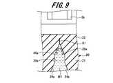
さらに、薬液M1がガスケット12によって筒孔6aの内側先端面6bに向けて押し出されると、図9に示すように、2つの被加圧面25a、25aには、さらに薬液M1からの圧力により、互いに離れる方向に力が加わる。そのため、2つの被加圧面25a、25aの先端には、スリットS1が形成される。Further, when the chemical liquid M1 is pushed out toward the inner
また、薬液M1がガスケット12によって筒孔6aの内側先端面6bに向けてさらに押し出されると、図10に示すように、2つの被加圧面25a、25aがさらに互いに離れてスリットS1が閉端部22の先端に向けて進行する。Further, when the chemical liquid M1 is further pushed out toward the inner
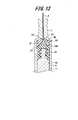
薬液M1がガスケット12によって筒孔6aの内側先端面6bに向けてさらに押し出されると、図11に示すように、開裂部25の先端が開裂する。そして、シール部材20の閉端部22における開裂部25が設けられた箇所には、開口部23と連通し、薬液M1が通液可能な通液口T1が形成される。これにより、筒体6の筒孔6aと針管3が、シール部材20の開口部23及び通液口T1を介して連通し、薬液M1が針管3から排出されて、生体に投与される。When the chemical solution M1 is further pushed out toward the inner
そして、図12及び図13に示すように、ガスケット12の先端部12bがシール部材20の開口部23に挿入されるまで摺動移動すると、薬液M1の投与動作が完了する。ここで、シール部材20の開口部23は、ガスケット12の先端部12bの形状と相補的な略円錐台形状に形成されている。これにより、ガスケット12の先端部12bをシール部材20の開口部23内に隙間なく挿入することができる。その結果、シール部材20とガスケット12との間に残る薬液M1の量を少なくすることができる。Then, as shown in FIGS. 12 and 13, when the
また、本体部21における閉端部22の近傍に先端側リブ部21aを設け、この先端側リブ部21aが筒体6の内側先端面6bに隣接している。これにより、薬液M1を排出する際に、内側先端面6bとシール部材20の閉端部22の隙間から、先端側リブ部21aと基端側リブ部21bとの間に薬液M1が入り込むことを防ぐことができる。Further, a front
また、シール部材20の閉端部22は、シリンジ2における筒体6の内側先端面6bの形状と相補的に略円錐台形状に形成されている。このため、薬液M1を排出する際に、内側先端面6bとシール部材20の閉端部22との間に残る薬液M1の量を少なくすることができる。Further, the
また、本例のシール部材20では、開裂する開裂部25を直線状に形成し、開裂する方向を一つの方向にしている。これにより、薬液M1からの圧力により開裂部25に加わる応力を集中させることができ、開裂部25が開裂する際に生じる抵抗を小さくすることができる。その結果、薬液M1を投与する際にシール部材20の閉端部22における開裂部25を開裂し易くでき、薬液M1の投与動作を容易に行うことができる。Moreover, in the sealing
2.第2の実施の形態例
次に、図14から図17を参照して、第2の実施の形態例にかかるプレフィルドシリンジについて説明する。
図14は、プレフィルドシリンジを示す断面図である。2. Second Embodiment Next, a prefilled syringe according to a second embodiment will be described with reference to FIGS. 14 to 17.
FIG. 14 is a cross-sectional view showing a prefilled syringe.
図14に示す第2の実施の形態例にかかるプレフィルドシリンジ41は、シリンジ2における筒体6の筒孔6a内に薬液M1と粉状の薬剤N1を収納させたものである。この第2の実施の形態例にかかるプレフィルドシリンジ41と、第1の実施の形態例にかかるプレフィルドシリンジ1と異なるところは、シール部材20を配置する箇所である。そのため、ここでは第1の実施の形態例にかかるプレフィルドシリンジ1と共通する部分には、同一の符号を付して重複した説明を省略する。A
図14に示すプレフィルドシリンジ41は、薬液M1と薬剤N1を混合させて、混合した薬液M1及び薬剤N1を生体に投与するものである。シール部材20は、シリンジ2における筒体6の筒孔6a内に配置されている。また、シール部材20は、筒孔6a内における軸方向の中間部に摺動移動可能に配置されている。The
筒孔6aにおけるシール部材20と押し子4のガスケット12によって形成される空間には、薬液M1が充填されている。また、筒体6の内壁及び内側先端面6bとシール部位20によって、薬剤収納空間が形成されている。薬剤収納空間には、粉状の薬剤N1が収納されている。薬液M1及び薬剤N1を混合する状態では、薬液M1は、シール部材20とガスケット12によって筒孔6a内に液密に封止される。これにより、薬液M1と薬剤N1を混合する前に、薬液M1が漏れ出し、使用者の意図に反して薬液M1と薬剤N1が混合されることを防ぐことができる。The space formed by the
また、シリンジ2の固定部7には、キャップ51が装着されている。キャップ51は、略円筒状に形成されており、基端側が開口し、先端側が閉じている。また、キャップ51の筒孔51a内の先端側には、封止部51bが設けられている。そして、キャップ51の筒孔51a内に針管3の針先3a及び固定部7が挿入されると、封止部51bには、針管3の針先3aが穿刺される。これにより、針管3から薬剤N1が漏れ出ることを防ぐことができる。Further, a
次に、第2の実施の形態例にかかるプレフィルドシリンジ41の投与動作について図15~図17を参照して説明する。
図15~図17はプレフィルドシリンジの投与動作を示す断面図である。Next, the administration operation of the
15 to 17 are sectional views showing the administration operation of the prefilled syringe.
まず、図15に示すように、使用者は、押し子4の押し棒11を押圧し、ガスケット12を内側先端面6bに向けて摺動移動させる。これにより、シール部材20には、ガスケット12によって薬液M1の圧力が加わり、シール部材20の開裂部25が開裂する。その結果、薬液M1が収納された空間と、薬剤N1が収納された空間がシール部材20の開裂部25に形成された通液口T1を介して連通する。First, as shown in FIG. 15, the user presses the
次に、図16に示すように、押し棒11をさらに押圧し、ガスケット12を内側先端面6bに向けて摺動移動させると、ガスケット12のシール部材20に接触する。そして、薬液M1は、ガスケット12に押し出されて、シール部材20に形成された通液口T1を通過して薬剤N1側の空間に流れ込む。これにより、薬液M1と薬剤N1を混合させることができ、薬液M1と薬剤N1からなる混合液M2が生成される。なお、図15及び図16に示すように、薬液M1と薬剤N1との混合作業は、キャップ51をシリンジ2の固定部7に装着した状態で行われる。また、押し子4の押し棒11を押し引きすることで、薬液M1と薬剤N1との混合作業を効率よく行うことができる。Next, as shown in FIG. 16, when the
次に、図17に示すように、キャップ51を外した後で、使用者が押し子4の押し棒11をさらに押圧し、ガスケット12を内側先端面6bに向けてさらに摺動移動させると、シール部材20は、ガスケット12と共に筒孔6a内を内側先端面6bに向けて摺動移動する。その結果、薬液M1と薬剤N1との混合液M2は、シール部材20及びガスケット12に押し出されて、針管3から排出される。これにより、プレフィルドシリンジ41の投与動作が完了する。Next, as shown in FIG. 17, after removing the
その他の構成は、第1の実施の形態例にかかるプレフィルドシリンジ1と同様であるため、それらの説明は省略する。このような構成を有するプレフィルドシリンジ41によっても、上述した第1の実施の形態例にかかるプレフィルドシリンジ1と同様の作用効果を得ることができる。Other configurations are the same as those of the prefilled syringe 1 according to the first embodiment, and thus description thereof is omitted. Also with the
以上、本発明の実施の形態例について、その作用効果も含めて説明した。しかしながら、本発明のシール部材及びプレフィルドシリンジは、上述の実施形態に限定されるものではなく、請求の範囲に記載した発明の要旨を逸脱しない範囲内で種々の変形実施が可能である。The embodiment of the present invention has been described above including its effects. However, the seal member and the prefilled syringe of the present invention are not limited to the above-described embodiments, and various modifications can be made without departing from the scope of the invention described in the claims.
上述した実施の形態例では、シール部材20を一つだけ設けた例を説明したが、これに限定されるものではない。例えば、シリンジにおける筒体の筒孔内に複数のシール部材を配置し、種類の異なる複数の薬液をシリンジ内に収納させてもよい。In the embodiment described above, an example in which only one
また、針管をシリンジに固定した例を説明したが、これに限定されるものではない。針管とシリンジを互いに着脱可能に構成し、薬液を投与する際に針管をシリンジに装着するようにしてもよい。Moreover, although the example which fixed the needle tube to the syringe was demonstrated, it is not limited to this. The needle tube and the syringe may be configured to be detachable from each other, and the needle tube may be attached to the syringe when the drug solution is administered.
1、41…プレフィルドシリンジ、 2…シリンジ、 3…針管、 3a…針先、 3b…基端部、 4…押し子、 5…キャップ、 5a…筒孔、 6…筒体、 6a…筒孔、 6b…内側先端面、 7…固定部(保持部)、 11…押し棒、 12…ガスケット、 12a…被接続部、 12b…先端部、 20…シール部材、 21…本体部、 21a…先端側リブ部、 21b…基端側リブ部、 21c…離間部、 22…閉端部、 23…開口部、 24…押圧部、 24a…押圧面、 25…開裂部、 25a…被加圧面、 25b…直線部、 M1…薬液、M2…混合液、 N1…薬剤、 S1…スリット、 T1…通液口1, 41 ... Prefilled syringe, 2 ... Syringe, 3 ... Needle tube, 3a ... Needle tip, 3b ... Base end, 4 ... Pusher, 5 ... Cap, 5a ... Cylindrical hole, 6 ... Cylindrical body, 6a ... Cylindrical hole, 6b ... Inner tip surface, 7 ... Fixing part (holding part), 11 ... Push bar, 12 ... Gasket, 12a ... Connected part, 12b ... Tip part, 20 ... Seal member, 21 ... Main body part, 21a ... Rib on the tip side Part, 21b ... proximal rib part, 21c ... separating part, 22 ... closed part, 23 ... opening part, 24 ... pressing part, 24a ... pressing surface, 25 ... cleaving part, 25a ... pressurized surface, 25b ... straight line Part, M1 ... chemical solution, M2 ... mixture, N1 ... drug, S1 ... slit, T1 ... fluid inlet
Claims (13)
Translated fromJapanese基端に形成された開口部と、前記筒体の内壁との間で液密なシールを形成可能な密着部とを有する筒状の本体部と、
前記本体部の先端に前記本体部と連続して一体に形成され、前記本体部の先端を封止する閉端部と、
前記閉端部に形成され、前記開口部と連通した開裂部と、を備え、
前記本体部は、前記筒体内を摺動可能なガスケットと共に前記筒体内に配置され、前記ガスケットよりも前記筒体内における先端側に位置することにより、前記ガスケット及び前記筒体と共に前記薬液を収納する薬液収納空間を形成し、
前記薬液収納空間に所定の圧力が加わることにより、前記開裂部が開裂して前記閉端部に前記開口部と連通した通液口が形成される
シール部材。In a seal assembly that is used in a syringe assembly including a syringe having a cylindrical body that can be filled with a chemical solution, and disposed in the cylindrical body,
A cylindrical main body having an opening formed at the base end and a close contact portion capable of forming a liquid-tight seal between the inner wall of the cylindrical body;
A closed end that is formed integrally and continuously with the main body at the tip of the main body, and seals the tip of the main body;
A cleaving portion formed at the closed end portion and communicated with the opening portion,
The main body is disposed in the cylinder together with a gasket that is slidable in the cylinder, and stores the chemical solution together with the gasket and the cylinder by being positioned closer to the distal end in the cylinder than the gasket. Form a chemical storage space,
A sealing member in which a predetermined pressure is applied to the chemical solution storage space, whereby the cleaving portion is cleaved and a liquid passing port communicating with the opening is formed in the closed end portion.
請求項1に記載のシール部材。The seal member according to claim 1, wherein a portion of the closed end portion where the cleavage portion is provided is formed thinner than other portions.
請求項1に記載のシール部材。The seal member according to claim 1, wherein the cleaving portion has two pressed surfaces that approach each other toward a tip of the closed end portion.
請求項3に記載のシール部材。The seal member according to claim 3, wherein the main body portion has a tapered pressing portion in which the flow path is continuously narrowed between the opening portion and the cleavage portion as it approaches the closed end portion.
前記開口部の近傍の前記本体部の外周面にリング状に設けられ、前記密着部として機能する基端側リブ部と、
前記押圧部の近傍の前記本体部の外周面にリング状に設けられ、前記本体部が前記筒体内に配置された際に、前記筒体の内壁から離間するように形成された離間部と、を有する
請求項4に記載のシール部材。The body part is
A proximal rib portion provided in a ring shape on the outer peripheral surface of the main body portion in the vicinity of the opening, and functioning as the contact portion;
A separation portion provided in a ring shape on the outer peripheral surface of the main body portion in the vicinity of the pressing portion, and formed so as to be separated from the inner wall of the cylindrical body when the main body portion is disposed in the cylindrical body; The seal member according to claim 4.
前記離間部の先端側で、かつ前記閉端部の近傍の前記本体部の外周面にリング状に設けられ、前記密着部として機能する先端側リブ部をさらに有する
請求項5に記載のシール部材。The body part is
The sealing member according to claim 5, further comprising a front-side rib portion that is provided in a ring shape on the outer peripheral surface of the main body portion near the distal end side of the separation portion and in the vicinity of the closed end portion, and functions as the contact portion. .
請求項1から6のいずれか1項に記載のシール部材。The seal member according to any one of claims 1 to 6, wherein the opening is opened in a shape complementary to a shape of a tip portion of the gasket.
請求項1から7のいずれか1項に記載のシール部材。The seal member according to any one of claims 1 to 7, wherein the cleavage portion is formed linearly along a direction orthogonal to the axial direction of the cylindrical body.
請求項1から8に記載のいずれか1項に記載のシール部材。The seal member according to any one of claims 1 to 8, wherein a front end surface of the closed end portion is formed in a shape complementary to a shape of an inner front end surface of the cylindrical body.
薬液を充填可能な筒体を有するシリンジと、を備え、
前記シール部材が前記筒体内に配置されている
シリンジ組立体。A sealing member according to any one of claims 1 to 9,
A syringe having a cylindrical body that can be filled with a chemical solution,
The syringe assembly, wherein the seal member is disposed in the cylinder.
前記シリンジは、前記針管を保持する保持部を有する
請求項10に記載のシリンジ組立体。It further comprises a needle tube having a needle tip that can puncture a living body,
The syringe assembly according to claim 10, wherein the syringe has a holding portion that holds the needle tube.
前記筒体内に摺動可能に配置され、前記シール部材よりも基端側に位置するガスケットと、
前記シール部材、前記ガスケット及び前記筒体によって形成された薬液収納空間に収納された前記薬液と、
を備えたプレフィルドシリンジ。A syringe assembly according to claim 10 or 11,
A gasket that is slidably disposed in the cylindrical body and is located on the proximal side of the seal member;
The chemical solution stored in the chemical solution storage space formed by the seal member, the gasket and the cylindrical body;
Prefilled syringe with
前記シール部材と前記筒体の内側先端面との間に形成された薬剤収納空間に、前記薬液と混合される薬剤が収納されている
請求項12に記載のプレフィルドシリンジ。
The seal member is slidably disposed in an axial intermediate portion of the cylindrical body,
The prefilled syringe according to claim 12, wherein a medicine mixed with the drug solution is stored in a medicine storage space formed between the seal member and an inner front end surface of the cylindrical body.
Priority Applications (3)
| Application Number | Priority Date | Filing Date | Title |
|---|---|---|---|
| JP2018508121AJPWO2017170634A1 (en) | 2016-03-30 | 2017-03-29 | Seal member, syringe assembly, and prefilled syringe |
| EP17775171.6AEP3437679A4 (en) | 2016-03-30 | 2017-03-29 | Seal member, syringe assembly, and prefilled syringe |
| US16/141,848US20190022326A1 (en) | 2016-03-30 | 2018-09-25 | Seal member, syringe assembly, and prefilled syringe |
Applications Claiming Priority (2)
| Application Number | Priority Date | Filing Date | Title |
|---|---|---|---|
| JP2016067698 | 2016-03-30 | ||
| JP2016-067698 | 2016-03-30 |
Related Child Applications (1)
| Application Number | Title | Priority Date | Filing Date |
|---|---|---|---|
| US16/141,848ContinuationUS20190022326A1 (en) | 2016-03-30 | 2018-09-25 | Seal member, syringe assembly, and prefilled syringe |
Publications (1)
| Publication Number | Publication Date |
|---|---|
| WO2017170634A1true WO2017170634A1 (en) | 2017-10-05 |
Family
ID=59965813
Family Applications (1)
| Application Number | Title | Priority Date | Filing Date |
|---|---|---|---|
| PCT/JP2017/012794CeasedWO2017170634A1 (en) | 2016-03-30 | 2017-03-29 | Seal member, syringe assembly, and prefilled syringe |
Country Status (4)
| Country | Link |
|---|---|
| US (1) | US20190022326A1 (en) |
| EP (1) | EP3437679A4 (en) |
| JP (1) | JPWO2017170634A1 (en) |
| WO (1) | WO2017170634A1 (en) |
Cited By (1)
| Publication number | Priority date | Publication date | Assignee | Title |
|---|---|---|---|---|
| KR20210131356A (en)* | 2019-02-27 | 2021-11-02 | 벡톤 디킨슨 프랑스 | A valve stopper for a medical injection device and a medical injection device for dispensing at least one composition |
Citations (4)
| Publication number | Priority date | Publication date | Assignee | Title |
|---|---|---|---|---|
| US3380451A (en)* | 1965-06-14 | 1968-04-30 | Robert E. Porter | Two compartment syringe |
| JPS5121295U (en)* | 1974-08-03 | 1976-02-17 | ||
| JPH11502731A (en)* | 1995-03-22 | 1999-03-09 | アボツト・ラボラトリーズ | Prefilled syringe drug delivery system |
| DE102009051863B3 (en)* | 2009-10-29 | 2011-02-10 | Schulz, Günther, Prof. Dr. | Dual piston syringe for direct injection of gel-like fluid and another fluid for local anesthesia into urethra of patient, has enlargement provided at surface of tube, and chamber pointed and slotted upto transition in enlargement |
Family Cites Families (3)
| Publication number | Priority date | Publication date | Assignee | Title |
|---|---|---|---|---|
| US1712069A (en)* | 1924-01-30 | 1929-05-07 | Cook Lab Inc | Hypodermic syringe |
| FR2086687A5 (en)* | 1970-04-06 | 1971-12-31 | Fabr Fraises Dentaires | Disposable hypodermic syringe - with loading cartridge |
| US4055177A (en)* | 1976-05-28 | 1977-10-25 | Cohen Milton J | Hypodermic syringe |
- 2017
- 2017-03-29EPEP17775171.6Apatent/EP3437679A4/ennot_activeWithdrawn
- 2017-03-29JPJP2018508121Apatent/JPWO2017170634A1/enactivePending
- 2017-03-29WOPCT/JP2017/012794patent/WO2017170634A1/ennot_activeCeased
- 2018
- 2018-09-25USUS16/141,848patent/US20190022326A1/ennot_activeAbandoned
Patent Citations (4)
| Publication number | Priority date | Publication date | Assignee | Title |
|---|---|---|---|---|
| US3380451A (en)* | 1965-06-14 | 1968-04-30 | Robert E. Porter | Two compartment syringe |
| JPS5121295U (en)* | 1974-08-03 | 1976-02-17 | ||
| JPH11502731A (en)* | 1995-03-22 | 1999-03-09 | アボツト・ラボラトリーズ | Prefilled syringe drug delivery system |
| DE102009051863B3 (en)* | 2009-10-29 | 2011-02-10 | Schulz, Günther, Prof. Dr. | Dual piston syringe for direct injection of gel-like fluid and another fluid for local anesthesia into urethra of patient, has enlargement provided at surface of tube, and chamber pointed and slotted upto transition in enlargement |
Non-Patent Citations (1)
| Title |
|---|
| See also references ofEP3437679A4* |
Cited By (4)
| Publication number | Priority date | Publication date | Assignee | Title |
|---|---|---|---|---|
| KR20210131356A (en)* | 2019-02-27 | 2021-11-02 | 벡톤 디킨슨 프랑스 | A valve stopper for a medical injection device and a medical injection device for dispensing at least one composition |
| JP2022522172A (en)* | 2019-02-27 | 2022-04-14 | ベクトン ディキンソン フランス | Valve stopper for medical injection device and medical injection device for injecting at least one composition |
| JP7531505B2 (en) | 2019-02-27 | 2024-08-09 | ベクトン ディキンソン フランス | Valve stopper for a medical injection device and medical injection device for injecting at least one composition - Patents.com |
| KR102788920B1 (en)* | 2019-02-27 | 2025-04-01 | 벡톤 디킨슨 프랑스 | Valve stopper for a medical infusion device and a medical infusion device for injecting at least one composition |
Also Published As
| Publication number | Publication date |
|---|---|
| EP3437679A1 (en) | 2019-02-06 |
| US20190022326A1 (en) | 2019-01-24 |
| JPWO2017170634A1 (en) | 2019-02-07 |
| EP3437679A4 (en) | 2019-09-11 |
Similar Documents
| Publication | Publication Date | Title |
|---|---|---|
| US10603427B2 (en) | Packaging body and packaging assembly | |
| JP4226787B2 (en) | Needleless syringe with prefilled cartridge | |
| US4886495A (en) | Vial-based prefilled syringe system for one or two component medicaments | |
| JP4682850B2 (en) | Prefilled syringe | |
| US6749590B2 (en) | Syringe barrel and plunger assembly having ellipsoidal configurations | |
| JP2001112867A (en) | Syringe containing drug | |
| JP2007185319A5 (en) | ||
| JPS6258745B2 (en) | ||
| JP2003159328A (en) | Two-chamber type prefilled syringe | |
| JP2697663B2 (en) | Multiple chemical solution injection tool | |
| JP2007215775A (en) | Medicine storage container and manufacturing method of medicine storage container | |
| WO2017057476A1 (en) | Medical resin-made hollow needle, medical instrument set using same, and outer cylinder provided with puncture part | |
| WO2012043162A1 (en) | Medical instrument with attached needle | |
| WO2012043161A1 (en) | Medical instrument with attached needle | |
| EP2898912A1 (en) | Drug administration instrument | |
| JP2012010930A (en) | Medicine administration appliance | |
| JP2002078799A (en) | Liquid injection appliance | |
| WO2017170634A1 (en) | Seal member, syringe assembly, and prefilled syringe | |
| WO2018173925A1 (en) | Female syringe and syringe kit | |
| CN105148358B (en) | Multi-component container | |
| JP2008099728A (en) | Syringe serving also as container | |
| JP4110569B2 (en) | Prefilled syringe kit | |
| JP2002035126A (en) | Pre-filled syringe | |
| JP2012029918A (en) | Gasket, prefilled syringe and plugging method | |
| JP2005034419A (en) | Cap, and production method of prefilled syringe |
Legal Events
| Date | Code | Title | Description |
|---|---|---|---|
| WWE | Wipo information: entry into national phase | Ref document number:2018508121 Country of ref document:JP | |
| NENP | Non-entry into the national phase | Ref country code:DE | |
| WWE | Wipo information: entry into national phase | Ref document number:2017775171 Country of ref document:EP | |
| ENP | Entry into the national phase | Ref document number:2017775171 Country of ref document:EP Effective date:20181030 | |
| 121 | Ep: the epo has been informed by wipo that ep was designated in this application | Ref document number:17775171 Country of ref document:EP Kind code of ref document:A1 |