WO2017166695A1 - Blood gas analyzer - Google Patents
Blood gas analyzerDownload PDFInfo
- Publication number
- WO2017166695A1 WO2017166695A1PCT/CN2016/097630CN2016097630WWO2017166695A1WO 2017166695 A1WO2017166695 A1WO 2017166695A1CN 2016097630 WCN2016097630 WCN 2016097630WWO 2017166695 A1WO2017166695 A1WO 2017166695A1
- Authority
- WO
- WIPO (PCT)
- Prior art keywords
- liquid
- test
- assembly
- pipe
- test card
- Prior art date
- Legal status (The legal status is an assumption and is not a legal conclusion. Google has not performed a legal analysis and makes no representation as to the accuracy of the status listed.)
- Ceased
Links
Images


Classifications
- G—PHYSICS
- G01—MEASURING; TESTING
- G01N—INVESTIGATING OR ANALYSING MATERIALS BY DETERMINING THEIR CHEMICAL OR PHYSICAL PROPERTIES
- G01N27/00—Investigating or analysing materials by the use of electric, electrochemical, or magnetic means
- G01N27/26—Investigating or analysing materials by the use of electric, electrochemical, or magnetic means by investigating electrochemical variables; by using electrolysis or electrophoresis
- G01N27/416—Systems
- G01N27/4163—Systems checking the operation of, or calibrating, the measuring apparatus
- G—PHYSICS
- G01—MEASURING; TESTING
- G01N—INVESTIGATING OR ANALYSING MATERIALS BY DETERMINING THEIR CHEMICAL OR PHYSICAL PROPERTIES
- G01N27/00—Investigating or analysing materials by the use of electric, electrochemical, or magnetic means
- G01N27/26—Investigating or analysing materials by the use of electric, electrochemical, or magnetic means by investigating electrochemical variables; by using electrolysis or electrophoresis
- G01N27/416—Systems
- G—PHYSICS
- G01—MEASURING; TESTING
- G01N—INVESTIGATING OR ANALYSING MATERIALS BY DETERMINING THEIR CHEMICAL OR PHYSICAL PROPERTIES
- G01N33/00—Investigating or analysing materials by specific methods not covered by groups G01N1/00 - G01N31/00
- G01N33/48—Biological material, e.g. blood, urine; Haemocytometers
- G—PHYSICS
- G01—MEASURING; TESTING
- G01N—INVESTIGATING OR ANALYSING MATERIALS BY DETERMINING THEIR CHEMICAL OR PHYSICAL PROPERTIES
- G01N2333/00—Assays involving biological materials from specific organisms or of a specific nature
- G01N2333/435—Assays involving biological materials from specific organisms or of a specific nature from animals; from humans
Definitions
- the inventionrelates to the technical field of medical technology, in particular to a blood gas analyzer.
- the blood gas analyzeris a commonly used medical device, and the blood gas analyzer has a reagent package, and the reagent package stores a calibration liquid for calibration of the electrode to be measured. In order to ensure the stability of the calibration solution components, it must be well sealed.
- the reagent package on the marketmainly consists of a casing, a hose, a hose valve and the like. The hose valve can be inserted around the housing assembly position, so that the hook portion is stuck into the card hole, and the casing and the rubber hose valve are pressed tightly to realize the closing of the rubber tube; the hook portion is separated from the card hole, and the casing and the rubber hose valve are relaxed.
- the hoseFor the compression of the hose, the hose relies on its own elasticity to lift the hose valve to achieve the conduction of the hose. Although this can realize the on-off control of the hose, it has the following disadvantages: the reagent package needs to be pressed by the hose valve for a long time to prevent the leakage of the calibration liquid in the transportation and storage process, and the long-term compression state makes the hose easy to bond. Together, it can not rebound, causing the pipeline to be blocked; the action of the valve pressing the hose is not reliable, and there is a hidden danger that the liquid leakage may not be completely crushed.
- a blood gas analyzercomprising a test card assembly and a reagent package assembly
- the test card assemblycomprising at least a test card body provided with a calibration liquid port
- the reagent package assemblycomprising at least a rotary switch assembly, a liquid storage device, an air intake device, and a sample introduction device for a liquid inlet needle
- the rotary switch assemblycomprising a first nozzle provided in communication with the liquid storage device, a second nozzle communicating with the sample introduction device, and a fixed valve body connected to the third nozzle of the intake device
- a rotating body having a connecting pipethe two ends of the liquid inlet needle are respectively connected with the second nozzle and the calibration liquid port, and the rotating body is disposed inside the fixed valve body and can be rotated relative to the fixed valve body to realize the first nozzle It is in communication with the second nozzle, or the second nozzle and the third nozzle are connected, or the second nozzle is closed.
- the liquid storage deviceis in communication with the sample introduction device, and the calibration liquid can be extracted;
- the sample introduction deviceis in communication with the air intake device to perform air extraction;
- the second nozzleis closed, that is, the sample introduction device is closed, so that the test card is closed. The action of extracting the test solution is performed.
- the blood gas analyzeruses the rotary switch assembly to realize the on-off control of different pipes without pressing and loosening the hose action, and there is no hidden danger of the pipeline blockage, and at the same time, when the rotary switch assembly is in the third state, the first nozzle is effectively closed to prevent calibration. The liquid leaked.
- the test card bodyis further provided with a liquid pipe, an inlet port and an electrode circuit board.
- the liquid pipeincludes a test liquid pipe, a calibration liquid pipe and an electrode pipe connected to the electrode circuit board, and one end of the test liquid pipe and the inlet The sample port is connected, and the other end is connected with the calibration liquid pipe and the electrode pipe.
- the end of the calibration liquid pipe away from the test liquid pipeis connected with the calibration liquid port, and the liquid level of the calibration liquid pipe is higher than the liquid level of the test liquid.
- the calibration liquid portis separated from the reagent package assembly, and the test liquid is stored in the electrode pipe and the calibration liquid pipe. Since the liquid level of the calibration liquid pipe is higher than the liquid level of the test liquid, there is no external force.
- the calibration liquid port of the inventiondoes not need to be provided with a sealing plug, and the reagent package assembly directly communicates with the calibration liquid port, and there is no problem of debris generated by piercing the sealing plug, and the debris pollution is eliminated.
- the electrodecauses a hidden danger of test rejection.
- the liquid level of the calibrator pipeis recessed with a leak-proof groove with an opening facing upward.
- the test card bodyis further provided with a liquid pipe, an inlet port, an air suction port and an electrode circuit board.
- the liquid pipeincludes a test liquid pipe, a waste liquid chamber and an electrode pipe connected to the electrode circuit board, and two test liquid pipes. End and injection separately The mouth and the electrode pipe are connected, and one end of the electrode pipe away from the test liquid pipe is connected with the liquid inlet of the waste liquid cavity, and the liquid outlet of the waste liquid cavity is connected with the suction port, and the liquid outlet is located above the liquid inlet.
- the suction portis separated from the external device, and the calibration liquid is stored in the waste liquid chamber. Since the liquid outlet of the waste liquid chamber is located above the liquid inlet, the calibration liquid cannot be discharged from the liquid outlet without external force.
- the air outlet of the present inventiondoes not need to be provided with a sealing plug, and the external device directly communicates with the air suction port, and there is no problem of debris generated by piercing the sealing plug, and the debris is contaminated to cause the test to be scrapped. Hidden dangers.
- the waste liquid chambercomprises at least a first waste liquid chamber and a second waste liquid chamber arranged side by side, a liquid discharge port connecting the first waste liquid chamber and the second waste liquid chamber, and the bottom of the first waste liquid chamber is provided
- the liquid inlet, the top of the second waste liquid chamberis provided with a liquid outlet, and the liquid discharge port is located at a side close to the liquid outlet.
- the calibration liquidis stored in the first waste liquid chamber, a liquid discharge port is arranged between the first waste liquid chamber and the second waste liquid chamber, and the liquid discharge port is located on the side close to the liquid outlet, and is connected There is a difference in section between the first waste liquid chamber and the top of the second waste liquid chamber, the liquid discharge port and the waste liquid chamber, and the calibration liquid cannot flow from the first waste liquid chamber into the second waste liquid chamber due to its own liquid tension, further Prevent liquid from leaking out of the suction port.
- a support columnis disposed in the first waste liquid chamber and the second waste liquid chamber. By setting the support column, the test film on the test card is prevented from falling into the waste liquid chamber when the test card is pumped through the suction port.
- the blood gas analyzerfurther comprises a test valve assembly provided with a pressing member
- the test card bodyfurther comprises a liquid pipeline
- the test card assemblyfurther comprises a sealing membrane for sealing the liquid pipeline
- the sealing membraneis an elastic composite membrane
- the liquid pipelineis The opposite surface of the sealing film is provided with a valve groove
- the sealing filmis located between the valve groove and the pressing member
- the pressing memberis provided with a pressing head matched with the shape of the valve groove.
- valve grooveis arranged in the test liquid pipe, and is integrated with the test liquid pipe, there is no excess cavity, no air bubbles remain, and the amount of the test liquid is reduced, and the test accuracy is improved; there is no need to set the on/off switch rubber plug and the test card body
- the sealing film covering the channel switch rubber plugavoids gas leakage problems, reduces the number of parts, facilitates production, and reduces product defect rate.
- the bottom of the valve grooveis provided with a protrusion protruding toward one side of the sealing film.
- the protrusionis embedded in the sealing film to make the sealing effect of the test liquid pipe better.
- test valve assemblyfurther includes a first driving device that drives the pressing member to reciprocate toward one side of the valve groove.
- the fixed valve bodyis in an interference fit with the rotating body.
- the structure of the pipeis closed by the wall surface of the rotating body, and the structure design is ingenious.
- the blood gas analyzerfurther comprises a reagent package valve control assembly
- the reagent package valve control assemblyfurther comprises a rotary cover sleeved on the rotating body and a second driving device for driving the rotary cover to rotate.
- the second driving devicedrives the rotating cover and the rotating body to realize a rotating motion, and uses the rotary switch assembly to realize on-off control of different pipes.
- test card bodyfurther comprises an inlet, a suction port, an electrode circuit board and a liquid pipeline
- liquid pipelinecomprises a test liquid pipeline, a calibration liquid pipeline, a waste liquid chamber and an electrode pipeline connected to the electrode circuit board, One end of the test liquid pipe is connected with the inlet, the other end is connected with the calibrator pipe and the electrode pipe, and one end of the calibrator pipe away from the test liquid pipe is connected with the calibrator port, and the liquid level of the calibrator pipe is the highest.
- the liquid pipeis higher than the liquid level of the test liquid, and the end of the electrode pipe away from the test liquid pipe is connected with the liquid inlet of the waste liquid chamber, and the liquid outlet of the waste liquid chamber is connected with the air suction port, and the liquid outlet is located above the liquid inlet .
- the test liquidcannot flow through the highest liquid level of the calibration liquid pipeline, and the calibration liquid cannot flow out from the liquid outlet of the waste liquid chamber to prevent the liquid from communicating with the calibration liquid port and the liquid outlet. Flow out in the suction port to prevent liquid contamination.
- the blood gas analyzerfurther comprises a test valve assembly provided with a pressing member
- the test card bodyfurther comprises an inlet, an electrode circuit board and a liquid pipeline
- the test card assemblyfurther comprises a sealing membrane for sealing the liquid pipeline
- the liquid pipelinea valve groove is disposed on the opposite side of the sealing film, the sealing film is located between the valve groove and the pressing member, and the pressing member is provided with an indenter matching the shape of the valve groove
- the liquid pipecomprises a test liquid pipe, a calibration liquid pipe and The electrode pipe connected to the electrode circuit board, one end of the test liquid pipe is connected with the injection port, the other end is connected with the calibration liquid pipe and the electrode pipe, and the end of the calibration liquid pipe away from the test liquid pipe is connected with the calibration liquid port
- the liquid level of the standard liquid pipeis higher than the liquid level of the test liquid. Prevent liquid from flowing out of the calibrated liquid port and avoid leakage problems, and improve the accuracy of the blood gas analyzer test.
- the blood gas analyzerfurther comprises a test valve assembly provided with a pressing member
- the test card bodyfurther comprises an inlet, a suction port, an electrode circuit board and a liquid pipe
- the test card assemblyfurther comprises a sealing film for closing the liquid pipe.
- the opposite side of the liquid pipe and the sealing filmis provided with a valve groove, the sealing film is located between the valve groove and the pressing member, and the pressing member is provided with a pressure head matching the shape of the valve groove;
- the liquid pipeincludes the test liquid pipe and the waste liquid chamber And an electrode pipe connected to the electrode circuit board, the two ends of the test liquid pipe are respectively connected with the inlet port and the electrode pipe, and one end of the electrode pipe away from the test liquid pipe is connected with the liquid inlet of the waste liquid cavity, and the waste liquid cavity is discharged.
- the liquid portis connected to the suction port, and the liquid outlet is located above the liquid inlet. Prevent liquid from flowing out of the suction port and avoid leakage problems, and improve the accuracy of the blood gas analyzer test.
- the liquid pipelineincludes a calibration liquid pipeline, and one end of the test liquid pipeline connected to the electrode pipeline is further connected with the calibration liquid pipeline and the electrode pipeline, and one end of the calibration liquid pipeline away from the test liquid pipeline is connected with the calibration liquid inlet.
- the liquid level of the calibration liquid pipelineis higher than the liquid level of the test liquid. Prevent liquid from flowing out of the suction port and the calibration liquid port, and avoid leakage problems, and improve the accuracy of the blood gas analyzer test.
- the blood gas analyzerfurther includes a piston pump assembly
- the test card bodyfurther includes an air suction port
- the piston pump assemblyincludes a suction needle that communicates with the air suction port at one end, a connection head that communicates with the air suction needle, and is connected with the connection head.
- the piston and the third driving devicethat drive the piston to reciprocate linearly. During the test, the third driving device drives the piston to retreat, so that the liquid pipeline in the main body of the test card generates a negative pressure, and the calibrator, air or test liquid is carried in the liquid pipeline to complete the extraction of each medium.
- the blood gas analyzerfurther comprises a sealing member, the sealing member is sleeved on the liquid inlet needle and the air suction needle, and the outer wall of the test card body is provided with a sealing groove matching the shape of the sealing member.
- the blood gas analyzeris better in preventing liquid leakage.
- the sealing memberis sealed between the inlet needle and the suction needle, and the reagent package assembly and the piston pump assembly are separated from the test card body. Under the premise of ensuring the seal, it also avoids the hidden dangers of test scrapping caused by debris contamination of the electrode.
- the blood gas analyzerfurther includes a slider assembly, the slider assembly is disposed opposite to the test card body, and is located at a side of the test card body facing the electrode circuit board, and the slider assembly includes a slider, a first fixing seat, and two ends And a first compression spring respectively corresponding to the slider and the fixing seat, the slider is provided with a first plug protruding toward a side of the test card body, and the test card body is provided with a first limiting slot that cooperates with the first plug.
- the slideris inserted into the first limiting slot by the first compression spring under the action of the first compression spring to realize positioning of the test card body.
- the blood gas analyzerfurther comprises a heating component
- the test card bodyfurther comprises an electrode circuit board
- the heating componentis disposed opposite to the test card body, and is located on a side of the test card body facing away from the electrode circuit board
- the heating componentcomprises the electrode a first heating body disposed opposite to the circuit board, a heating body fixing bracket to which the first heating body is fixed, a fourth driving device for driving the heating body fixing bracket to reciprocate toward the electrode circuit board side, and the heating body fixing bracket is provided for testing
- the slideris inserted into the first limiting slot by the first compression spring to realize the initial positioning of the test card body; the second plug is in the first Under the action of the four driving device, the side of the test card body is moved, and the second plug is inserted into the second limiting slot to realize secondary positioning of the test card body, so that the positioning of the test card body is more accurate and reliable, and
- the first heating bodyheats the liquid in the test card body to bring the liquid to a prescribed temperature.
- the slider assembly and the heating assemblyperform bilateral positioning on the front and back sides of the test card body, so that the test card body is evenly stressed and is not deformed by force.
- the blood gas analyzerfurther includes a pop-up assembly directly under the test card body, the pop-up assembly includes a second mount, a pressing block disposed opposite the bottom of the test card body, and two ends respectively and the second mount a second compression spring that abuts against the pressing block.
- the blood gas analyzerfurther comprises a test component, the test component is disposed opposite to the test card body and located on a side of the test card body facing the electrode circuit board, and the test component comprises a detection module and a second heating disposed opposite to the electrode circuit board.
- the side protrusionis provided with a matching rib
- the housingThe top side is convexly provided with a pushing rib on one side of the slider, and the pushing rib is located between the matching rib and the test card main body.
- the second heating device on the fifth driving devicedrives the housing to move to the side of the electrode circuit board, the first plug is inserted into the first limiting slot, and the second plug is inserted into the second limiting slot;
- the electrode circuit boardis heated, the liquid in the test card body reaches a predetermined temperature, and the current and voltage signals generated on the electrode circuit board are transmitted to the host through the detection module to realize the calibration liquid and the test liquid.
- the fifth driving device of the testing componentdrives the housing to retreat. Since the pushing rib is located between the matching rib and the test card main body, when the pushing rib on the housing contacts the matching rib, the pushing rib continues with the housing.
- the sliderretreats with the push ribs, the first compression spring is compressed, and the first plug on the slider is disengaged from the first limit groove.
- the fifth driving devicemoves the housing forward, and the slider moves forward together under the action of the first compression spring, and the rib pushes the pushing rib when the housing moves to the pushing rib and
- the first plug of the slider assemblyreturns to the initial position, which is convenient for the next round of testing, and the structure of the ribs and the pushing ribs is skillfully designed to realize the position control of the sliding component of the test component. The action is more reliable.
- the blood gas analyzerfurther comprises a reagent package valve control component, a piston pump component, a heating component and a test component
- the test valve componentfurther comprises a first driving device for driving the pressing member to reciprocate to the valve groove side
- the reagent packageThe valve control assembly further includes a rotating cover sleeved on the rotating body and a second driving device for driving the rotating cover to rotate.
- the piston pump assemblyincludes a suction needle that communicates with the suction port at one end, a connector that communicates with the suction needle, and a connection.
- the heating assemblycomprises a first heating body disposed opposite to the electrode circuit board, a heating body fixing bracket fixed with the first heating body, and a driving heating body fixing bracket a fourth driving device for reciprocating one side of the electrode circuit board, the testing component comprising a detecting module, a second heating body disposed opposite to the electrode circuit board, a housing fixed with the detecting module and the second heating body, and a driving housing toward the electrode A fifth driving device that reciprocates on one side of the circuit board.
- test valve assemblythe reagent package valve control assembly, the piston pump assembly, the heating assembly and the test assembly are all controlled by independent driving devices, and the blood gas analyzer is more flexible in control than the conventional blood gas analyzer rotary dial synchronous driving system. Shorten the work cycle.
- first driving device, the third driving device, the fourth driving device and the fifth driving deviceare linear stepping motors
- the second driving deviceis a rotary stepping motor.
- the first driving device, the second driving device, the third driving device, the fourth driving device and the fifth driving deviceare both stepping motors, and the speed of the stepping motor can be compared with the rotary synchronous driving system of the traditional blood gas analyzer. Adjust, the action is gentle and controllable, the noise is small, and the structure is simplified, and the assembly efficiency is improved.
- first driving device, the second driving device, the third driving device, the fourth driving device and the fifth driving deviceare each provided with a reset optocoupler.
- the reset optocouplerdetects the initial position of the motor shaft, eliminates the position error after each movement, and makes the control more precise.
- the present inventionhas the following beneficial effects:
- the liquid storage deviceis in communication with the sample introduction device, and the calibration liquid can be extracted; when the rotary switch assembly is in the second nozzle and the third When the nozzle is in a state of communication, the sample introduction device is in communication with the air intake device to perform air extraction; when the rotary switch assembly is in the state in which the second nozzle is closed, the second nozzle is closed, that is, the sample introduction device is closed, so that The test card performs the action of extracting the test solution.
- the blood gas analyzeruses the rotary switch assembly to realize the on-off control of different pipes without pressing and loosening the hose action, and there is no hidden danger of the pipeline blockage, and at the same time, when the rotary switch assembly is in the third state, the first nozzle is effectively closed to prevent calibration. The liquid leaked.
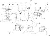
- FIG. 1is a schematic structural view of a blood gas analyzer according to an embodiment of the present invention.
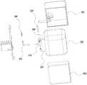
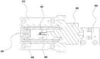
- FIG. 2is a schematic exploded view of a blood gas analyzer according to an embodiment of the present invention.
- FIG. 3is a schematic view showing the connection of a test card assembly and a reagent package assembly according to an embodiment of the present invention
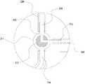
- FIG. 4is a schematic structural view of a reagent package assembly according to an embodiment of the present invention.
- Figure 5is a schematic exploded view of a reagent pack assembly of an embodiment of the present invention.
- FIG. 6is a schematic view showing the connection of a reagent package assembly and a reagent package valve control assembly according to an embodiment of the present invention
- Figure 7is a schematic structural view of a piston pump assembly according to an embodiment of the present invention.
- FIG. 8is a schematic structural diagram of a test card assembly according to an embodiment of the present invention.
- FIG. 9is a schematic exploded view of a test card assembly according to an embodiment of the present invention.
- Figure 10is a cross-sectional view taken along line A-A of Figure 8.
- FIG 11is an enlarged view of I of Figure 10;
- FIG. 12is a schematic structural view of a test valve assembly according to an embodiment of the present invention.
- FIG. 13is a schematic diagram of a first working state of a test card assembly according to an embodiment of the present invention.
- FIG. 14is a schematic view showing a second working state of a test card assembly according to an embodiment of the present invention.
- FIG. 15is a schematic view showing a third working state of a test card assembly according to an embodiment of the present invention.
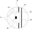
- Figure 16is an enlarged view of II of Figure 1;
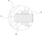
- Figure 17is an enlarged view of the portion III of Figure 1;
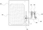
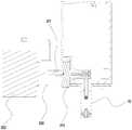
- FIG. 18is a schematic view showing the connection of a test card assembly, a heating assembly, and a test assembly according to an embodiment of the present invention
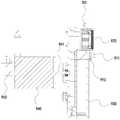
- Figure 19is an enlarged view of the IV of Figure 18;
- FIG. 20is a schematic structural view of a heating assembly according to an embodiment of the present invention.
- 21is a schematic structural diagram of a test component according to an embodiment of the present invention.
- Fig. 22is an enlarged view of Fig. 4;
- Test card assembly110. Test card body, 111. Inlet, 112. Calibration port, 113. Pumping port, 114. Sealing groove, 115. Electrode test slot, 116. First limit slot, 117 Second limit groove, 120. sealing film, 121. film, 122. elastic silicone film, 123. PET film, 130. electrode circuit board, 140. liquid pipe, 141. test liquid pipe, 1411. valve groove, 142. Calibration liquid pipeline, 1421. leak-proof tank, 1422. top, 143. waste liquid chamber, 1431. first waste liquid chamber, 1432. second waste liquid chamber, 1433. liquid discharge port, 1434. , 1435. Outlet, 144. Electrode tubing, 145. Waste tubing, 150. Seal, 160.
- Support column170. Syringe, 180. Syringe, 190. Protrusion, 20.
- Reagent pack assembly210 Rotary switch assembly, 211. fixed valve body, 212. rotating body, 213. connecting pipe, 214. first nozzle, 215. second nozzle, 216. third nozzle, 220. liquid storage device, 221.
- Outlet tube230. Intake device, 240. Sample introduction device, 241. Infusion needle, 242.
- Inlet tube250. Housing, 251. Front shell, 252. Back shell, 260. Rotating handle, 270. Support Block, 30. reagent package valve control assembly, 310. rotary cover, 320. Drive unit, 321. first motor shaft, 330. first optocoupler, 40. piston pump assembly, 410.
- heating body fixing cover760. motor fixing bracket, 770. second guiding shaft, 780. buckle position, 80. bounce assembly, 810. second fixing seat, 820. pressing block, 830.
- a blood gas analyzerincludes a test card assembly 10 and a reagent package assembly 20, and the test card assembly 10 includes an inlet 111 and a calibration liquid port 112.
- the test card body 110 of the air suction port 113 and the liquid pipe 140, the sealing film 120 of the liquid sealing pipe 140, the electrode circuit board 130 disposed on the test card body 110, and the reagent package assembly 20includes at least the rotary switch assembly 210 and the liquid storage device 220.
- the air intake device 230 and the sample introduction device 240 provided with the liquid inlet needle 241, the rotary switch assembly 210includes a fixed valve body 211 and a rotating body 212.
- the rotating body 212is disposed inside the fixed valve body 211 and is rotatable relative to the fixed valve body 211.
- the rotating main body 212is provided with a connecting pipe 213.
- the fixed valve body 211is provided with a first nozzle 214 communicating with the liquid storage device 220, a second nozzle 215 communicating with the sampling device 240, and communicating with the air inlet device 230.
- the third nozzle 216, the two ends of the liquid inlet needle 241are respectively connected with the second nozzle 215 and the calibration liquid port 112; rotating the rotating body 212 can cause the rotary switch assembly 210 to be in the first state, the second state or the
- the third stateis that the second state is that the second nozzle 215 communicates with the first nozzle 214 through the connecting pipe 213; the second state is that the second nozzle 215 and the third nozzle 216 are connected through the connecting pipe 213; Both the nozzle 215 and the first nozzle 214 are closed.
- the liquid storage device 220is in communication with the sample introduction device 240 to perform extraction of the calibration liquid; when the rotary switch assembly 210 is in the second state, the injection device 240 and the intake device 230 In communication, air extraction is performed; when the rotary switch assembly 210 is in the third state, the second nozzle 215 is closed, that is, the sample introduction device 240 is closed, so that the test card performs the action of extracting the test liquid.
- the blood gas analyzerutilizes the rotary switch assembly 210 to realize on-off control of different pipes without pressing and loosening the hose action, and there is no hidden danger of the pipe blockage, and at the same time, when the rotary switch assembly 210 is in the third state, the first nozzle 214 is effectively closed. Prevent leakage of the calibration solution.
- the fixed valve body 211has an interference fit with the rotating body 212, and the wall of the rotating body 212 is directly used to achieve the closing of the pipe.
- the reagent package assembly 20further includes a housing 250 having a placement cavity, the fixed valve body 211 is fixed in the placement cavity, and the connection pipe 213 is an L-shaped pipe.
- the rotating handle 260is connected to the rotating body 212, and the rotating handle 260 is exposed on the outer casing 250.
- the rotary switch assembly 210can be adjusted to different states, which is convenient to use.
- the connecting duct 213can also be set to other shapes according to actual needs.
- the liquid storage device 220is a calibration liquid bag disposed in the placement cavity, and the outer casing 250 has the function of protecting the calibration liquid bag, preventing the calibration liquid bag from being contaminated, and setting the calibration liquid bag.
- the outer casing 250includes a front casing 251 and a rear casing 252. The front casing 251 and the rear casing 252 are detachably connected to facilitate installation of the calibration liquid bag.
- the front case 251 and the rear caseare fixed by screws, and the state of the outer casing 250 near the rotating handle 260 is provided with a status indicator (not shown in the drawing), so that the user can understand what the current rotary switch assembly 210 is in. status.
- the blood gas analyzerfurther includes a reagent package valve control assembly 30.
- the reagent package valve control assembly 30further includes a rotary cover 310 sleeved on the rotating body 212 and a second drive for driving the rotary cover 310 to rotate.
- Device 320The second driving device 320 drives the rotating cover 310 and the rotating body 212 to realize a rotating motion, and the rotating switch assembly 210 realizes on-off control of different pipes.
- the second driving device 320is a rotating stepping motor
- the rotating stepping motoris provided with a first motor shaft 321
- the rotating cover 310is designed with an optocoupler sensing wall (not shown in the drawing), and the rotating cover 310 It is fixed to the first motor shaft 321 by screws.
- the first motor shaft 321drives the rotating cover 310 and the rotating body 212 to perform a rotating motion, thereby implementing the on/off control of the sample inlet and the intake line of the reagent package assembly 20.
- the reagent package valve control assembly 30further includes a first optocoupler 330 that detects and controls the initial position of the first motor shaft 321 to eliminate positional errors after each rotational motion.
- the reagent package assembly 20further includes a support base 270.
- the support base 270is fixed to the outer casing 250.
- the sample introduction device 240includes a liquid inlet needle 241 and a liquid inlet tube 242.
- the liquid inlet needle 241is fixed on the support.
- the socket 270is connected to the calibration liquid port 112 of the test card to facilitate the supply of the sample.
- One end of the liquid inlet tube 242is sleeved on the liquid inlet needle 241, and the other end is sleeved on the second nozzle 215, and the liquid inlet needle 241 is passed.
- the inlet pipe 242is in communication with the second nozzle 215.
- the air intake device 230is an air tube that is sleeved on the third nozzle 216. The air tube communicates with the atmosphere, and directly extracts air from the atmosphere.
- the blood gas analyzerfurther includes a piston pump assembly 40 including a suction needle 410 having one end communicating with the suction port 113 and one end being connected to the other end of the suction needle 410.
- the air pipe 420, the connecting head 430 communicating with the other end of the air exhausting pipe 420, the piston 440 connected to the connecting head 430, the third driving device 450 for driving the piston 440 to linearly reciprocate, the air suction needle 410 and the air suction pipe 420are fixed to the reagent package On the support base 270 of the assembly 20.
- the third driving device 450drives the piston 440 to retreat, so that the liquid pipe 140 in the test card body 110 generates a negative pressure, and the calibrator, air or test liquid is carried in the liquid pipe 140 to complete the extraction of each medium. .
- the third driving device 450is a linear stepping motor, and the linear stepping motor is provided with a second motor shaft 451.
- the piston pump assembly 40further includes a piston pump subassembly provided with a piston 440 and a connecting head 430.
- the second optical coupling 460, the first fixing bracket 470, the piston pump subassemblyfurther includes a pump body 480, and the piston pump subassembly is sleeved into the first fixing bracket 470, wherein the piston 440 is screwed to the second motor shaft 451, and the third driving
- the device 450is fixed to the first fixed branch by screws
- the piston pump subassemblyis fixed to the frame 470 and simultaneously.
- the second motor shaft 451drives the piston 440 to reciprocate along the pump body 480, and the second optical coupling 460 detects the initial position of the second motor shaft 451 to eliminate the position error after each reciprocating motion. .
- the blood gas analyzerfurther includes a sealing member 150.
- the sealing member 150is sleeved on the liquid inlet needle 241 and the air suction needle 410.
- the outer wall of the test card body 110is provided with a sealing groove 114 matching the shape of the sealing member 150. .
- the blood gas analyzeris better in preventing liquid leakage.
- the sealing member 150is sealed to the inlet needle 241 and the suction needle 410, the reagent package assembly 20 and the piston pump assembly 40 and the test card, respectively. After the main body 110 is separated, under the premise of ensuring the sealing, the hidden trouble of the test scrapping caused by the debris contamination of the electrode is avoided.
- the liquid pipe 140 of the test card assembly 10includes a test liquid pipe 141, a calibrator pipe 142, a waste liquid chamber 143, and an electrode pipe 144 that is in contact with the electrode circuit board 130, and a test liquid pipe 141.
- One endis connected to the inlet 111, the other end is connected to the calibration liquid pipe 142 and the electrode pipe 140, and one end of the calibration liquid pipe 142 away from the test liquid pipe 141 is connected to the calibration liquid port 112, and the electrode pipe 140 is away from the test liquid pipe.
- One end of the 141is in communication with the liquid inlet 1434 of the waste liquid chamber 143, and the liquid outlet 1435 of the waste liquid chamber 143 is in communication with the suction port 113.
- the liquid outlet 1435is located above the liquid inlet 1434, and the liquid level of the calibration liquid pipe 142 The highest point is higher than the liquid level of the test solution.
- the air suction port 113 and the calibration liquid port 112are separated from the reagent package assembly 20, and the calibration liquid is stored in the waste liquid chamber 143.
- the test liquidis stored in the electrode pipe 140 and the calibration liquid pipe 142 due to the waste liquid chamber.
- the liquid outlet 1435 of the 143is located above the liquid inlet 1434. When the calibration liquid cannot flow out from the liquid outlet 1435 without external force, the air outlet 113 communicating with the liquid outlet 1435 does not leak liquid, preventing liquid.
- the highest liquid level of the calibration liquid pipe 142that is, the top portion 1422 of the pipe is higher than the liquid level of the test liquid, and the test liquid cannot flow through the highest liquid level of the calibration liquid pipe 142 without external force, and the liquid is not It will leak from the calibration liquid port 112 to prevent liquid contamination.
- the conventional test cardthere is no need to provide a sealing plug on the calibration liquid port 112 and the suction port 113 of the present invention, and the external device directly communicates with the calibration liquid port 112 and the suction port 113, and there is no piercing of the sealing plug. The problem of chipping is eliminated, and the hidden contamination of the electrode caused by the debris is eliminated.
- the waste liquid chamber 143includes a first waste liquid chamber 1431 and a second waste liquid chamber 1432 arranged side by side, and a liquid discharge port 1433 that communicates with the first waste liquid chamber 1431 and the second waste liquid chamber 1432, first The bottom of the waste liquid chamber 1431 is provided with a liquid inlet 1434, and the top of the second waste liquid chamber 1432 is provided with a liquid outlet 1435, and the liquid discharge port 1433 is located at a side close to the liquid outlet 1435.
- the calibration liquidis stored in the first waste liquid chamber 1431, a liquid discharge port 1433 is disposed between the first waste liquid chamber 1431 and the second waste liquid chamber 1432, and the liquid discharge port 1433 is located near the liquid outlet 1435.
- the liquid chamber 1431flows into the second waste liquid chamber 1432 to further prevent liquid from leaking from the air suction port 113.
- the waste liquid chamber 143can also be set more than one according to actual needs.
- two support columns 160are disposed in the first waste liquid chamber 1431 and the second waste liquid chamber 1432.
- the test film 120is prevented from being trapped in the waste liquid chamber 143 when the test card is evacuated through the suction port 113.
- the first waste liquid chamber 1431 and the second waste liquid chamber 1432may also be provided with more than one support column 160 according to actual needs.
- the liquid pipe 140further includes a waste liquid pipe 145, and a waste liquid pipe 145 is connected between the liquid outlet 1435 and the suction port 113.
- the top portion 1422 of the calibrating fluid conduit 142is recessed with a leak-proof groove 1421 having an opening facing upward.
- the leakage preventing groove 1421can also be disposed between the top portion 1422 of the calibrating liquid pipe 142 and the end of the calibrating liquid pipe 142 and the test liquid pipe 141 connected according to actual needs.
- the test card body 110is further provided with an electrode test slot 115, and the bottom of the electrode duct 140 is connected to the electrode circuit board 130 through the electrode test slot 115.
- the test card assembly 10further includes a syringe needle 241 that is fixed to the injection port 111 of the test card body 110 and communicates with the syringe 180, and the test liquid is stored in the syringe 180.
- the blood gas analyzerfurther includes a test valve assembly 50 provided with a pressing member 510.
- the sealing film 120is an elastic composite film, and the test liquid pipe 141 is opposite to the sealing film 120.
- the valve groove 1411is provided on the surface.
- the sealing film 120is located between the valve groove 1411 and the pressing member 510, and the pressing member 510 is provided with a pressing head 511 that is shaped to match the valve groove 1411.
- the test liquid pipe 141When the pressing member 510 presses the sealing film 120 to the side of the valve groove 1411, the test liquid pipe 141 is closed; the sealing film 120 is an elastic composite film, and when the pressing member leaves the sealing film 120, the sealing film 120 is on its own The elastic deformation leaves the valve groove 1411, and the test liquid pipe 141 is opened.
- the valve groove 1411is disposed in the test liquid pipe 141, and is integrated with the test liquid pipe 141. There is no excess cavity, no air bubbles remain, and the amount of the test liquid is reduced, and the test accuracy is improved; the switch card body 110 does not need to be provided with an on/off switch.
- the rubber plug and the sealing film 120 for covering the channel switch rubber plugavoid leakage problems, reduce the number of parts, facilitate production, and reduce product defect rate.
- the test valve assembly 50further includes a first driving device 520 and a third optical coupling 530 for driving the pressing member 510 to reciprocate toward the valve slot 1411.
- the first driving device 520The linear stepping motor is provided with a third motor shaft 521, and the pressing member 510 is screwed to the third motor shaft 521.
- the third motor shaft 521is driven.
- the pressing member 510reciprocates in the axial direction of the linear stepping motor.
- the third optocoupler 530detects and controls the initial position of the third motor shaft 521 to eliminate the position error of each reciprocating motion.
- the bottom of the valve groove 1411is provided with a projection 190 which is convex toward the side of the sealing film 120, and the projection 190 has a rib shape.
- the protruding portion 190is fitted into the sealing film 120 to make the sealing effect of the test liquid pipe 141 better.
- the sealing film 120includes a film 121, an elastic silicone film 122, and a PET film 123.
- the film 121is adhered between the test card body 110 and the elastic silicone film 122.
- the PET film 123Covering the side of the elastic silicone film 122 facing away from the valve groove 1411.
- the adhesive film 121functions as the adhesive sealing film 120 and the test card main body 110, so that the test card pipes are closed; the elastic silicone film 122 functions as a sealing, and is filled into the valve groove 1411 by the elasticity of the elastic silicone film 122 itself; the PET film 123
- the support and resetting actionensures that the sealing film 120 is deformed while ensuring effective sealing of the sealing film 120 after the external force is removed, and the sealing film 120 seals the liquid pipe 140 in the entire test card by using a flat and large-surface filming method, thereby further avoiding Air leak problem.
- the sealing film 120can also adopt other structural forms according to actual needs.
- Test card assembly 10test valve assembly 50, reagent pack assembly 20, reagent pack valve control assembly 30, and piston pump assembly 40 form the pumping subsystem of the blood gas analyzer. Before the test, the test card assembly 10 is inserted into the reagent package assembly 20, and the calibration liquid port 112 of the test card main body 110 is connected to the liquid inlet needle 241 on the support base 270, and the air suction port 113 and the support base 270 of the test card main body 110 are tested.
- the upper suction needle 410is coupled and sealed by a seal 150 to allow the tubing of the reagent pack assembly 20 to communicate with the tubing of the test card assembly 10; the vent tube that inserts the connector 430 of the piston pump assembly 40 into the support block 270
- the extraction tube 420is in communication with the extraction needle 410 such that the tubing of the piston pump assembly 40 is in communication with the tubing of the test card assembly 10; the abutment member 510 of the test valve assembly 50 is mounted in the valve slot 1411 of the test fluid conduit 141.
- the on/off control of the test liquid pipe 141is realized.
- the calibration liquidis first extracted: as shown in FIG. 2, FIG. 3 and FIG. 13, the second driving device 320 of the reagent package valve control assembly 30 is energized, and the first motor shaft 321 drives the rotating cover 310 and the rotating body 212 to rotate.
- the L-shaped pipe in the rotating body 212is respectively communicated with the first nozzle 214 and the second nozzle 215 of the reagent package assembly 20 to communicate with the calibration liquid pipe 142 and the electrode test slot 115 of the test card assembly 10;
- the first driving device 520 of the valve assembly 50is energized, and the third motor shaft 521 pushes the pressing member 510 forward to press the sealing film 120 onto the valve groove 1411 of the test liquid pipe 141, and the elastic silicone film 122 of the sealing film 120 is filled.
- the test liquid pipe 141is closed to the valve groove 1411; the third driving device 450 of the piston pump assembly 40 is energized, and the second motor shaft 451 drives the piston 440 to retreat to generate a negative pressure in the liquid pipe 140 of the test card assembly 10;
- the calibrator in the liquid storage device 220 of the reagent package assembly 20flows into the electrode through the rotating body 212, the inlet tube 242, the inlet needle 241, and the calibrator tube 142 of the test card assembly 10 under the action of a negative pressure. In the tank 115, the calibrator is completed. Extraction operation.
- the second driving device 320 of the reagent package valve control assembly 30is energized, and the first motor shaft 321 drives the rotating cover 310 and the rotating body 212 of the reagent package assembly 20 to rotate.
- the L-shaped pipe in the rotating body 212is respectively connected to the second nozzle 215 and the third nozzle 216 to communicate with the calibration liquid pipe 142 and the electrode test slot 115 of the test card assembly 10;
- a driving device 520still maintains the energized working state, and the pressing member 510 still presses the sealing film 120 on the valve groove 1411 to keep the test liquid pipe 141 sealed.
- the third driving device 450 of the piston pump assembly 40is energized, and the second motor shaft 451 drives the piston 440 to continue to retreat, so that a negative pressure is generated in the liquid pipe 140 of the test card assembly 10; under the action of the negative pressure, the reagent package
- the outside air of the assembly 20enters the electrode test slot 115 through the third nozzle 216, the rotating body 212, the second nozzle 215, the inlet tube 242, the inlet needle 241, and the calibrator tube 142 of the test card assembly 10, and is completed. Extraction of air.
- test liquidis extracted: as shown in FIG. 2, FIG. 3 and FIG. 15, the second driving device 320 of the reagent package valve control assembly 30 is energized, and the first motor shaft 321 drives the rotating body of the rotating cover 310 and the reagent package assembly 20.
- the rotation of the 212causes the L-shaped pipe in the rotating body 212 to separate from the first nozzle 214 and the third nozzle 216 respectively, that is, the liquid storage device 220 and the liquid inlet tube 242 are closed by the outer wall of the rotating body 212, so that the reagent package piping system is closed.
- the first driving device 520 of the test valve assembly 50is energized to move the pressing member 510 away from the valve groove 1411 of the test liquid pipe 141, and the sealing film 120 of the test card assembly 10 is elastically reset by the PET film 123 to open the test liquid pipe 141.
- the third driving device 450 of the piston pump assembly 40is energized, and the second motor shaft 451 drives the piston 440 to continue to retreat, so that a negative pressure is generated in the liquid pipe 140 of the test card assembly 10; under the action of the negative pressure, the syringe 180
- the test solutionpasses through the liquid inlet needle 241 of the test card assembly 10 and the test liquid pipe 141 into the electrode test slot 115 to complete the extraction of the test liquid.
- the blood gas analyzerfurther includes a slider assembly 60 .
- the slider assembly 60is disposed opposite to the test card body 110 and located on a side of the test card body 110 facing the electrode circuit board 130 .
- the buckle assembly 60includes a slider 610, a first fixing base 620, a first compression spring 630 respectively contacting the slider 610 and the fixing base, and a first guiding shaft 640 sleeved with the first compression spring 630, the first guiding One end of the shaft 640 is connected to the first fixing base 620, the other end passes through the guiding hole of the slider 610, and the slider 610 is provided with a first plug 611 protruding toward the side of the test card main body 110, and the side wall of the test card main body 110
- the first limiting groove 116is matched with the first plug 611.
- the slider 610is inserted into the first limiting slot 116 by the first compression spring 630 to realize the test card body 110.
- the first guide shaft 640acts as a guide to prevent the slider 610 from shifting during the movement.
- the blood gas analyzerfurther includes a heating assembly 70 disposed opposite to the test card body 110 and located on a side of the test card body 110 facing away from the electrode circuit board 130.
- 70includes a first heating body 710 disposed opposite to the electrode wiring board 130, a heating body fixing bracket 720 to which the first heating body 710 is fixed, and a fourth driving device for driving the heating body fixing bracket 720 to reciprocate toward the electrode wiring board 130 side.
- the device 730, the heating body fixing bracket 720is provided with a second plug 721 protruding toward the side of the test card body 110.
- the sidewall of the test card body 110is recessed with a second limiting slot 117 that cooperates with the second plug 721.
- the slider 610is inserted into the first limiting slot 116 by the first compression spring 630 to realize the test card body 110.
- the first plug 721is moved by the fourth driving device 730 to the test card main body 110 side, and the second plug 721 is inserted into the second limiting slot 117 to realize the second test card body 110.
- the positioningmakes the positioning of the test card body 110 more precise and reliable, and the liquid in the test card body 110 is heated by the first heating body 710 to bring the liquid to a predetermined temperature.
- the slider assembly 60 and the heating assembly 70perform bilateral positioning on the front and back sides of the test card body 110, so that the test card body 110 is evenly stressed and is not deformed by force.
- the fourth driving device 730is a linear stepping motor, and the linear stepping motor is provided with a fourth motor shaft 731.
- the heating assembly 70further includes a fourth optical coupling 740 and a heating body fixing cover. 750, the motor fixing bracket 760, the second guiding shaft 770 disposed on the motor fixing bracket 760, the heating body fixing bracket 720 and the heating body fixing cover 750 are provided with interlocking buckles 780.
- the fourth driving device 730is fixed to the motor fixing bracket 760 by screws, and the heating body fixing bracket 720 is sleeved on the second guiding shaft 770 of the motor fixing bracket 760, and is screwed with the fourth motor shaft 731, and the fixing body is fixed by the heating body 750.
- the first heating body 710is fixed to the heating body fixing bracket 720.
- the fourth driving device 730When the fourth driving device 730 is energized, the fourth motor shaft 731 drives the first heating body 710 to linearly reciprocate in the direction of the second guiding shaft 770.
- the fourth optocoupler 740detects and controls the initial position of the fourth motor shaft 731 to eliminate the position error after each reciprocating motion.
- the blood gas analyzerfurther includes a pop-up assembly 80 located directly below the test card body 110.
- the pop-up assembly 80includes a second mount 810 that is placed against the bottom of the test card body 110.
- the block 820has a second compression spring 830 opposite to the second fixing base 810 and the pressing block 820.
- Test card assembly 10is inserted into the reagent package group After the member 20, the slider assembly 60 and the heating assembly 70 fixedly position the test card body 110, the pressing member 510 is pressed down, and the second compression spring 830 is compressed by force; when the test is completed, the slider assembly 60 and the heating After the assembly 70 releases the fixing of the test card main body 110, the pressing block 820 rebounds upward by the second compression spring 830, thereby realizing the automatic bounce of the test card main body 110.
- the blood gas analyzerfurther includes a test component 90 disposed opposite to the test card body 110 and located on a side of the test card body 110 facing the electrode circuit board 130.
- the test component 90includes a detecting module 910, a second heating body 920 disposed opposite to the electrode circuit board 130, a housing 930 to which the detecting module 910 and the second heating body 920 are fixed, and a driving housing 930 to the electrode wiring board 130 side.
- the reciprocating fifth driving device 940has a slider 610 located above the housing 930. The bottom of the slider 610 protrudes from a side of the housing 930 with a matching rib 612. The top of the housing 930 faces the side of the slider 610.
- a pushing rib 931is disposed, and the pushing rib 931 is located between the matching rib 612 and the test card main body 110.
- the fifth driving device 940drives the second heating body 920 on the housing 930 to move toward the side of the electrode circuit board 130.
- the first plug 611is inserted into the first limiting slot 116, and the second The plug 721 is inserted into the second limiting slot 117; after the test component 90 is energized, the electrode circuit board 130 is heated to bring the liquid in the test card body 110 to a predetermined temperature, and the current generated on the electrode circuit board 130 is passed through the detecting module 910.
- the voltage signalis transmitted to the host to perform the test of the calibration liquid and the test liquid; after the test is completed, the fifth driving device 940 of the test assembly 90 drives the housing 930 to retreat, since the pushing rib 931 is located at the matching rib 612 and the test card main body 110. Meanwhile, when the pushing rib 931 on the casing 930 is in contact with the engaging rib 612, the pushing rib 931 continues to retreat as the casing 930 retreats, and the slider 610 retreats along with the pushing rib 931, the first compression spring 630 is compressed and slipped. The first plug 611 on the block 610 is disengaged from the first limiting slot 116.
- the fifth driving device 940moves the housing 930 forward, and the slider 610 moves forward together under the action of the first compression spring 630, and the rib 612 presses the pushing rib 931.
- the housing 930moves to no force between the pushing rib 931 and the matching rib 612, the first plug 611 of the slider assembly 60 returns to the initial position, facilitating the next round of testing, and skillfully designing the matching rib 612 and the pushing rib 931
- the structure of the test assembly 90controls the position of the slider assembly 60, and the action is more reliable.
- the fifth driving device 940is a linear stepping motor
- the detecting module 910is a test PCBA component
- the test PCBA componentis provided with a test probe 911
- the linear stepping motoris provided with a fifth.
- the motor shaft 941the housing 930 is fixed to the fifth motor shaft 941 by screws
- the test assembly 90further includes a fifth photocoupler 950.
- the linear fifth driving device 940is energized
- the fifth motor shaft 941drives the housing 930 to reciprocate in the axial direction of the stepping motor, thereby implementing the testing function.
- the fifth optocoupler 950detects and controls the initial position of the fifth motor shaft 941 to eliminate the position error after each reciprocating motion.
- the test card assembly 10, the heating assembly 70, and the test assembly 90form a test and heating subsystem of the blood gas analyzer.
- the test card assembly 10is inserted into the reagent package assembly 20, and the first heating body 710 of the heating assembly 70 faces the test card body 110.
- the position of the electrode test slot 115, the second heating body 920 of the test assembly 90, and the test probe 911correspond to the electrode circuit board 130 on the test card body 110.
- the pumping subsystem of the blood gas analyzeroperates to draw the calibrator or test solution into the electrode test slot 115; the fourth drive device 730 of the heating assembly 70 is energized, and the fourth motor shaft 731
- the first heating body 710is pushed forward and pressed onto the sealing film 120 of the test card assembly 10; the first heating body 710 is energized to generate heat to heat the sealing film 120 of the test card assembly 10 and the electrode testing slot 115 to test the electrode.
- the liquid in the tank 115is heated to a set temperature; the fifth driving unit 940 of the test assembly 90 is energized, and the fifth motor shaft 941 drives the entire housing 930 to push forward and press the electrode circuit board 130 on the test card assembly 10.
- the second heating body 920is electrically heated to generate heat to heat the electrode circuit board 130, thereby indirectly heating the liquid in the electrode testing slot 115, heating the liquid in the electrode testing slot 115 to a set temperature; testing of the test component 90
- the pin 911communicates with the output end of the electrode circuit board 130, and transmits current and voltage signals generated on the electrode circuit board 130 to the host to perform testing of the calibration liquid and the test liquid; when the test card assembly 10 After all the processes of pumping, heating, and testing are completed, the fourth drive unit 730 retracts the heating assembly 70, and the fifth driving unit 940 retracts the test assembly 90 to allow the test card to be removed.
- the first driving device 520, the second driving device 320, the third driving device 450, the fourth driving device 730, and the fifth driving device 940are both a stepping motor, a first driving device 520, and a second driving device.
- Device 320, third The driving device 450, the fourth driving device 730, and the fifth driving device 940may also adopt other driving methods such as other cylinders according to actual needs.
- the blood gas analyzer of the present inventionhas the following advantages:
- the test card assembly 10does not need the steel needle piercing action, effectively solves the problem of the test card debris; design the secondary waste liquid chamber, the liquid inlet 1434 is designed at the lower end, and the liquid outlet 1435 is designed at the upper end to solve the liquid from the suction port 113 Leakage problem; the highest surface of the calibration liquid pipe 142 is higher than the test liquid pipe 141, and the leakproof groove 1421 is designed at the highest point to solve the problem of liquid leakage from the calibration liquid port 112; the valve groove 1411 is designed on the test liquid pipe 141, and tested The liquid pipe 141 is integrated, eliminating the need for cylindrical rubber plugs and filming parts, reducing the number of parts, reducing the risk of liquid leakage, and improving production efficiency.
- the reagent package assembly 20controls the opening and closing of the liquid path and the gas path by the rotary switch assembly 210 and the reagent package valve control assembly 30, and the rotary switch technology is mature, the action is reliable, and the problem of the reagent package pipe blockage and liquid leakage is effectively solved;
- the on/off of each liquid path of the liquid subsystemis controlled by an independent stepping motor, so that each on/off action can be simultaneously performed. Compared with the existing original turntable system, the waiting time of the turntable rotation is not required, so the work cycle can be shortened.
- each liquid channel of the pumping subsystemis controlled by an independent stepping motor.
- the speed of the stepping motoris adjustable, and the action is gentle. Controllable, no gear rotation noise and rod impact noise, so the noise is small, and at the same time the gear set, tie rod, spring, roller and other parts are eliminated, reducing the number of parts, simplifying the structure and improving assembly efficiency.
- the test and heating subsystemadopts the stepping motor control test component 90 and the heating component 70 to press and release the work, the action is stable and controllable, the noise is small, and the matching precision is high.
Landscapes
- Life Sciences & Earth Sciences (AREA)
- Health & Medical Sciences (AREA)
- Chemical & Material Sciences (AREA)
- Immunology (AREA)
- Molecular Biology (AREA)
- Pathology (AREA)
- Physics & Mathematics (AREA)
- Analytical Chemistry (AREA)
- Biochemistry (AREA)
- General Health & Medical Sciences (AREA)
- General Physics & Mathematics (AREA)
- Electrochemistry (AREA)
- Chemical Kinetics & Catalysis (AREA)
- Engineering & Computer Science (AREA)
- Biomedical Technology (AREA)
- Hematology (AREA)
- Urology & Nephrology (AREA)
- Food Science & Technology (AREA)
- Medicinal Chemistry (AREA)
- Investigating Or Analysing Biological Materials (AREA)
- Sampling And Sample Adjustment (AREA)
Abstract
Description
Translated fromChinese本发明涉及医疗技术领域,特别涉及一种血气分析仪。The invention relates to the technical field of medical technology, in particular to a blood gas analyzer.
血气分析仪属于常用的医疗设备,血气分析仪内有试剂包,该试剂包存储有定标液,用于对待测电极进行定标。为了保证定标液成分的稳定性,必须对其进行良好的密封。市面上的试剂包主要由壳体、胶管、胶管阀门等构成。胶管阀门可绕壳体装配位插入,使卡钩部卡入卡孔内,壳体、胶管阀门压紧胶管,实现胶管的关断;使卡钩部脱离卡孔外,壳体、胶管阀门放松对胶管的压紧,胶管依靠其自身的弹性,将胶管阀门顶起,实现胶管的导通。这种虽然能实现胶管的通断控制,但其存在以下缺点:试剂包在运输及存储过程中需靠胶管阀门长期压紧胶管防止定标液泄露,长期的压紧状态使胶管容易粘接在一起而不能回弹,造成管道堵塞;阀门压紧胶管的动作不可靠,存在不能完全压死管道截面造成液体泄漏的隐患。The blood gas analyzer is a commonly used medical device, and the blood gas analyzer has a reagent package, and the reagent package stores a calibration liquid for calibration of the electrode to be measured. In order to ensure the stability of the calibration solution components, it must be well sealed. The reagent package on the market mainly consists of a casing, a hose, a hose valve and the like. The hose valve can be inserted around the housing assembly position, so that the hook portion is stuck into the card hole, and the casing and the rubber hose valve are pressed tightly to realize the closing of the rubber tube; the hook portion is separated from the card hole, and the casing and the rubber hose valve are relaxed. For the compression of the hose, the hose relies on its own elasticity to lift the hose valve to achieve the conduction of the hose. Although this can realize the on-off control of the hose, it has the following disadvantages: the reagent package needs to be pressed by the hose valve for a long time to prevent the leakage of the calibration liquid in the transportation and storage process, and the long-term compression state makes the hose easy to bond. Together, it can not rebound, causing the pipeline to be blocked; the action of the valve pressing the hose is not reliable, and there is a hidden danger that the liquid leakage may not be completely crushed.
发明内容Summary of the invention
本发明的目的在于提供一种血气分析仪,能够避免管道堵塞和液体泄露的情况发生。It is an object of the present invention to provide a blood gas analyzer capable of avoiding the occurrence of pipe clogging and liquid leakage.
为实现本发明的目的,采取的技术方案是:In order to achieve the object of the present invention, the technical solution adopted is:
一种血气分析仪,包括测试卡组件和试剂包组件,测试卡组件至少包括设有定标液口的测试卡主体,试剂包组件至少包括旋转开关组件、储液装置、进气装置以及设有进液针的进样装置,旋转开关组件包括设有与储液装置连通的第一管口、与进样装置连通的第二管口、与进气装置连通的第三管口的固定阀体、以及设有连通管道的旋转主体,进液针的两端分别与第二管口和定标液口连通,旋转主体设置于固定阀体内部且可相对固定阀体转动以实现第一管口和第二管口连通、或者第二管口和第三管口连通、或者关闭第二管口。A blood gas analyzer comprising a test card assembly and a reagent package assembly, the test card assembly comprising at least a test card body provided with a calibration liquid port, the reagent package assembly comprising at least a rotary switch assembly, a liquid storage device, an air intake device, and a sample introduction device for a liquid inlet needle, the rotary switch assembly comprising a first nozzle provided in communication with the liquid storage device, a second nozzle communicating with the sample introduction device, and a fixed valve body connected to the third nozzle of the intake device And a rotating body having a connecting pipe, the two ends of the liquid inlet needle are respectively connected with the second nozzle and the calibration liquid port, and the rotating body is disposed inside the fixed valve body and can be rotated relative to the fixed valve body to realize the first nozzle It is in communication with the second nozzle, or the second nozzle and the third nozzle are connected, or the second nozzle is closed.
当旋转开关组件处于第一管口和第二管口连通的状态时,储液装置与进样装置连通,可进行定标液的抽取;当旋转开关组件处于第二管口和第三管口连通的状态时,进样装置与进气装置相连通,可进行空气的抽取;当旋转开关组件处于第二管口关闭的状态时,第二管口封闭,即进样装置关闭,以便测试卡进行抽取测试液动作。该血气分析仪利用旋转开关组件实现不同管道的通断控制,无需压紧及放松胶管动作,不存在管道堵塞隐患,同时旋转开关组件在第三状态时,第一管口有效封闭,防止定标液发生泄漏。When the rotary switch assembly is in a state in which the first nozzle and the second nozzle are in communication, the liquid storage device is in communication with the sample introduction device, and the calibration liquid can be extracted; when the rotary switch assembly is in the second nozzle and the third nozzle In the connected state, the sample introduction device is in communication with the air intake device to perform air extraction; when the rotary switch assembly is in the state in which the second nozzle is closed, the second nozzle is closed, that is, the sample introduction device is closed, so that the test card is closed. The action of extracting the test solution is performed. The blood gas analyzer uses the rotary switch assembly to realize the on-off control of different pipes without pressing and loosening the hose action, and there is no hidden danger of the pipeline blockage, and at the same time, when the rotary switch assembly is in the third state, the first nozzle is effectively closed to prevent calibration. The liquid leaked.
下面对技术方案进一步说明:The technical solution is further explained below:
进一步的是,测试卡主体还设有液体管道、进样口和电极线路板,液体管道包括测试液管道、定标液管道和与电极线路板相接的电极管道,测试液管道的一端与进样口连通,另一端与定标液管道和电极管道连通,定标液管道远离测试液管道的一端与定标液口连通,定标液管道的液位最高处高于测试液的液面。完成测试后,定标液口与试剂包组件脱离,测试液储存在电极管道和定标液管道内,由于定标液管道的液位最高处高于测试液的液面,在无外力的作用下测试液无法流过定标液管道的液位最高处,液体不会从定标液口泄露,防止液体污染。与传统的血气分析仪相比,本发明的定标液口无需设置密封塞,试剂包组件直接与定标液口连通,不存在因刺穿密封塞而产生碎屑的问题,消除碎屑污染电极造成测试报废的隐患。Further, the test card body is further provided with a liquid pipe, an inlet port and an electrode circuit board. The liquid pipe includes a test liquid pipe, a calibration liquid pipe and an electrode pipe connected to the electrode circuit board, and one end of the test liquid pipe and the inlet The sample port is connected, and the other end is connected with the calibration liquid pipe and the electrode pipe. The end of the calibration liquid pipe away from the test liquid pipe is connected with the calibration liquid port, and the liquid level of the calibration liquid pipe is higher than the liquid level of the test liquid. After the test is completed, the calibration liquid port is separated from the reagent package assembly, and the test liquid is stored in the electrode pipe and the calibration liquid pipe. Since the liquid level of the calibration liquid pipe is higher than the liquid level of the test liquid, there is no external force. The lower test solution cannot flow through the highest level of the calibrator pipe, and the liquid will not leak from the calibrator port to prevent liquid contamination. Compared with the traditional blood gas analyzer, the calibration liquid port of the invention does not need to be provided with a sealing plug, and the reagent package assembly directly communicates with the calibration liquid port, and there is no problem of debris generated by piercing the sealing plug, and the debris pollution is eliminated. The electrode causes a hidden danger of test rejection.
进一步的是,定标液管道的液位最高处凹设有开口朝上的防漏槽。防漏槽与定标液管道之间存在截面差,测试液因自身液体张力无法从防漏槽中流出,进一步防止液体从定标液口泄露出来。Further, the liquid level of the calibrator pipe is recessed with a leak-proof groove with an opening facing upward. There is a difference in section between the leakage preventing groove and the calibrating liquid pipe, and the test liquid cannot flow out of the leakage preventing groove due to the liquid tension of the liquid, thereby further preventing the liquid from leaking out from the calibrating liquid port.
进一步的是,测试卡主体还设有液体管道、进样口、抽气口和电极线路板,液体管道包括测试液管道、废液腔和与电极线路板相接的电极管道,测试液管道的两端分别与进样口和电极管道连通,电极管道远离测试液管道的一端与废液腔的进液口连通,废液腔的出液口与抽气口连通,出液口位于进液口的上方。完成测试后,抽气口与外部装置脱离,定标液储存在废液腔内,由于废液腔的出液口位于进液口的上方,在无外力的作用下定标液无法从出液口流出,则与出液口连通的抽气口不会出现液体泄露,防止液体污染。与传统的血气分析仪相比,本发明的抽气口无需设置密封塞,外部装置直接与抽气口连通,不存在因刺穿密封塞而产生碎屑的问题,消除碎屑污染电极造成测试报废的隐患。Further, the test card body is further provided with a liquid pipe, an inlet port, an air suction port and an electrode circuit board. The liquid pipe includes a test liquid pipe, a waste liquid chamber and an electrode pipe connected to the electrode circuit board, and two test liquid pipes. End and injection separatelyThe mouth and the electrode pipe are connected, and one end of the electrode pipe away from the test liquid pipe is connected with the liquid inlet of the waste liquid cavity, and the liquid outlet of the waste liquid cavity is connected with the suction port, and the liquid outlet is located above the liquid inlet. After the test is completed, the suction port is separated from the external device, and the calibration liquid is stored in the waste liquid chamber. Since the liquid outlet of the waste liquid chamber is located above the liquid inlet, the calibration liquid cannot be discharged from the liquid outlet without external force. When flowing out, there is no liquid leakage from the suction port that communicates with the liquid outlet, preventing liquid contamination. Compared with the traditional blood gas analyzer, the air outlet of the present invention does not need to be provided with a sealing plug, and the external device directly communicates with the air suction port, and there is no problem of debris generated by piercing the sealing plug, and the debris is contaminated to cause the test to be scrapped. Hidden dangers.
进一步的是,废液腔至少包括并排布置的第一废液腔和第二废液腔、连通第一废液腔和第二废液腔的排液口,第一废液腔的底部设有进液口,第二废液腔的顶部设有出液口,排液口位于靠近出液口的一侧。测试完成后,定标液储存在第一废液腔内,第一废液腔和第二废液腔之间设置了排液口,且排液口位于靠近出液口的一侧、并连通第一废液腔和第二废液腔的顶部,排液口和废液腔之间存在截面差,定标液因自身液体张力无法从第一废液腔流入第二废液腔内,进一步防止液体从抽气口泄漏出来。Further, the waste liquid chamber comprises at least a first waste liquid chamber and a second waste liquid chamber arranged side by side, a liquid discharge port connecting the first waste liquid chamber and the second waste liquid chamber, and the bottom of the first waste liquid chamber is provided The liquid inlet, the top of the second waste liquid chamber is provided with a liquid outlet, and the liquid discharge port is located at a side close to the liquid outlet. After the test is completed, the calibration liquid is stored in the first waste liquid chamber, a liquid discharge port is arranged between the first waste liquid chamber and the second waste liquid chamber, and the liquid discharge port is located on the side close to the liquid outlet, and is connected There is a difference in section between the first waste liquid chamber and the top of the second waste liquid chamber, the liquid discharge port and the waste liquid chamber, and the calibration liquid cannot flow from the first waste liquid chamber into the second waste liquid chamber due to its own liquid tension, further Prevent liquid from leaking out of the suction port.
进一步的是,第一废液腔内和第二废液腔内均设有支撑柱。通过设置支撑柱,防止测试卡在通过抽气口进行抽气时,测试卡上的密封膜陷入废液腔内。Further, a support column is disposed in the first waste liquid chamber and the second waste liquid chamber. By setting the support column, the test film on the test card is prevented from falling into the waste liquid chamber when the test card is pumped through the suction port.
进一步的是,血气分析仪还包括设有抵压件的测试阀门组件,测试卡主体还设有液体管道,测试卡组件还包括封闭液体管道的密封膜,密封膜为弹性复合膜,液体管道与密封膜的相对面设有阀门槽,密封膜位于阀门槽和抵压件之间,抵压件设有与阀门槽形状匹配的压头。当抵压件挤压密封膜向阀门槽一侧贴合,测试液管道实现关闭;密封膜为弹性复合膜,当挤压件离开密封膜时,密封膜靠自身的弹性变形离开阀门槽,测试液管道实现打开。阀门槽设置在测试液管道中,与测试液管道构成一体,不存在多余空腔,不残留气泡,同时减少测试液用量,提高测试准确性;测试卡主体上无需设置通断开关胶塞和用于覆盖通道开关胶塞的密封膜,避免漏气问题,减少零件数量,便于生产,降低产品不良率。Further, the blood gas analyzer further comprises a test valve assembly provided with a pressing member, the test card body further comprises a liquid pipeline, and the test card assembly further comprises a sealing membrane for sealing the liquid pipeline, the sealing membrane is an elastic composite membrane, and the liquid pipeline is The opposite surface of the sealing film is provided with a valve groove, the sealing film is located between the valve groove and the pressing member, and the pressing member is provided with a pressing head matched with the shape of the valve groove. When the pressing member presses the sealing film to the side of the valve groove, the test liquid pipe is closed; the sealing film is an elastic composite film, and when the pressing member leaves the sealing film, the sealing film is separated from the valve groove by its own elastic deformation, and the test is performed. The liquid pipe is opened. The valve groove is arranged in the test liquid pipe, and is integrated with the test liquid pipe, there is no excess cavity, no air bubbles remain, and the amount of the test liquid is reduced, and the test accuracy is improved; there is no need to set the on/off switch rubber plug and the test card body The sealing film covering the channel switch rubber plug avoids gas leakage problems, reduces the number of parts, facilitates production, and reduces product defect rate.
进一步的是,阀门槽底部设有向密封膜一侧凸起的突起部。密封膜填充到阀门槽上时,突起部镶入密封膜内,使测试液管道的密闭效果更好。Further, the bottom of the valve groove is provided with a protrusion protruding toward one side of the sealing film. When the sealing film is filled into the valve groove, the protrusion is embedded in the sealing film to make the sealing effect of the test liquid pipe better.
进一步的是,测试阀门组件还包括驱动抵压件向阀门槽一侧作往复运动的第一驱动装置。Further, the test valve assembly further includes a first driving device that drives the pressing member to reciprocate toward one side of the valve groove.
进一步的是,固定阀体与旋转主体过盈配合。利用旋转主体壁面实现管道的封闭,结构设计巧妙。Further, the fixed valve body is in an interference fit with the rotating body. The structure of the pipe is closed by the wall surface of the rotating body, and the structure design is ingenious.
进一步的是,血气分析仪还包括试剂包阀门控制组件,试剂包阀门控制组件还包括套设于旋转主体上的旋转盖、驱动旋转盖转动的第二驱动装置。第二驱动装置带动旋转盖和旋转主体实现旋转运动,利用旋转开关组件实现不同管道的通断控制。Further, the blood gas analyzer further comprises a reagent package valve control assembly, and the reagent package valve control assembly further comprises a rotary cover sleeved on the rotating body and a second driving device for driving the rotary cover to rotate. The second driving device drives the rotating cover and the rotating body to realize a rotating motion, and uses the rotary switch assembly to realize on-off control of different pipes.
进一步的是,测试卡主体还设有进样口、抽气口、电极线路板和液体管道,液体管道包括测试液管道、定标液管道、废液腔和与电极线路板相接的电极管道,测试液管道的一端与进样口连通,另一端与定标液管道和所述电极管道连通,定标液管道远离测试液管道的一端与定标液口连通,定标液管道的液位最高处高于测试液的液面,电极管道远离所述测试液管道的一端与废液腔的进液口连通,废液腔的出液口与抽气口连通,出液口位于进液口的上方。在无外力的作用下测试液无法流过定标液管道的液位最高处,定标液液无法从废液腔的出液口流出,防止液体从定标液口和与出液口连通的抽气口中流出,防止液体污染。Further, the test card body further comprises an inlet, a suction port, an electrode circuit board and a liquid pipeline, and the liquid pipeline comprises a test liquid pipeline, a calibration liquid pipeline, a waste liquid chamber and an electrode pipeline connected to the electrode circuit board, One end of the test liquid pipe is connected with the inlet, the other end is connected with the calibrator pipe and the electrode pipe, and one end of the calibrator pipe away from the test liquid pipe is connected with the calibrator port, and the liquid level of the calibrator pipe is the highest. The liquid pipe is higher than the liquid level of the test liquid, and the end of the electrode pipe away from the test liquid pipe is connected with the liquid inlet of the waste liquid chamber, and the liquid outlet of the waste liquid chamber is connected with the air suction port, and the liquid outlet is located above the liquid inlet . Under the action of no external force, the test liquid cannot flow through the highest liquid level of the calibration liquid pipeline, and the calibration liquid cannot flow out from the liquid outlet of the waste liquid chamber to prevent the liquid from communicating with the calibration liquid port and the liquid outlet. Flow out in the suction port to prevent liquid contamination.
进一步的是,血气分析仪还包括设有抵压件的测试阀门组件,测试卡主体还设有进样口、电极线路板和液体管道,测试卡组件还包括封闭液体管道的密封膜,液体管道与密封膜的相对面设有阀门槽,密封膜位于阀门槽和抵压件之间,抵压件设有与阀门槽形状匹配的压头;液体管道包括测试液管道、定标液管道和与电极线路板相接的电极管道,测试液管道的一端与进样口连通,另一端与定标液管道和电极管道连通,定标液管道远离测试液管道的一端与定标液口连通,定标液管道的液位最高处高于测试液的液面。防止液体从定标液口流出和避免漏气问题,提高血气分析仪测试的准确性。Further, the blood gas analyzer further comprises a test valve assembly provided with a pressing member, the test card body further comprises an inlet, an electrode circuit board and a liquid pipeline, and the test card assembly further comprises a sealing membrane for sealing the liquid pipeline, the liquid pipeline a valve groove is disposed on the opposite side of the sealing film, the sealing film is located between the valve groove and the pressing member, and the pressing member is provided with an indenter matching the shape of the valve groove; the liquid pipe comprises a test liquid pipe, a calibration liquid pipe and The electrode pipe connected to the electrode circuit board, one end of the test liquid pipe is connected with the injection port, the other end is connected with the calibration liquid pipe and the electrode pipe, and the end of the calibration liquid pipe away from the test liquid pipe is connected with the calibration liquid port, The liquid level of the standard liquid pipe is higher than the liquid level of the test liquid. Prevent liquid from flowing out of the calibrated liquid port and avoid leakage problems, and improve the accuracy of the blood gas analyzer test.
进一步的是,血气分析仪还包括设有抵压件的测试阀门组件,测试卡主体还设有进样口、抽气口、电极线路板和液体管道,测试卡组件还包括封闭液体管道的密封膜,液体管道与密封膜的相对面设有阀门槽,密封膜位于阀门槽和抵压件之间,抵压件设有与阀门槽形状匹配的压头;液体管道包括测试液管道、废液腔和与电极线路板相接的电极管道,测试液管道的两端分别与进样口和电极管道连通,电极管道远离测试液管道的一端与废液腔的进液口连通,废液腔的出液口与抽气口连通,出液口位于进液口的上方。防止液体从抽气口流出和避免漏气问题,提高血气分析仪测试的准确性。Further, the blood gas analyzer further comprises a test valve assembly provided with a pressing member, the test card body further comprises an inlet, a suction port, an electrode circuit board and a liquid pipe, and the test card assembly further comprises a sealing film for closing the liquid pipe. The opposite side of the liquid pipe and the sealing film is provided with a valve groove, the sealing film is located between the valve groove and the pressing member, and the pressing member is provided with a pressure head matching the shape of the valve groove; the liquid pipe includes the test liquid pipe and the waste liquid chamber And an electrode pipe connected to the electrode circuit board, the two ends of the test liquid pipe are respectively connected with the inlet port and the electrode pipe, and one end of the electrode pipe away from the test liquid pipe is connected with the liquid inlet of the waste liquid cavity, and the waste liquid cavity is discharged. The liquid port is connected to the suction port, and the liquid outlet is located above the liquid inlet. Prevent liquid from flowing out of the suction port and avoid leakage problems, and improve the accuracy of the blood gas analyzer test.
进一步的是,液体管道包括定标液管道,测试液管道与电极管道连通的一端还与定标液管道和所述电极管道连通,定标液管道远离测试液管道的一端与定标液口连通,定标液管道的液位最高处高于测试液的液面。防止液体从抽气口和定标液口流出、并避免漏气问题,提高血气分析仪测试的准确性。Further, the liquid pipeline includes a calibration liquid pipeline, and one end of the test liquid pipeline connected to the electrode pipeline is further connected with the calibration liquid pipeline and the electrode pipeline, and one end of the calibration liquid pipeline away from the test liquid pipeline is connected with the calibration liquid inlet. The liquid level of the calibration liquid pipeline is higher than the liquid level of the test liquid. Prevent liquid from flowing out of the suction port and the calibration liquid port, and avoid leakage problems, and improve the accuracy of the blood gas analyzer test.
进一步的是,血气分析仪还包括活塞泵组件,测试卡主体还设有抽气口,活塞泵组件包括一端与抽气口连通的抽气针、与抽气针连通的连接头、与连接头连接的活塞、驱动活塞作直线往复运动的第三驱动装置。在测试过程中,通过第三驱动装置带动活塞后退,使测试卡主体内的液体管道产生负压,使定标液、空气或测试液进行液体管道内,完成各个介质的抽取。Further, the blood gas analyzer further includes a piston pump assembly, and the test card body further includes an air suction port, and the piston pump assembly includes a suction needle that communicates with the air suction port at one end, a connection head that communicates with the air suction needle, and is connected with the connection head. The piston and the third driving device that drive the piston to reciprocate linearly. During the test, the third driving device drives the piston to retreat, so that the liquid pipeline in the main body of the test card generates a negative pressure, and the calibrator, air or test liquid is carried in the liquid pipeline to complete the extraction of each medium.
进一步的是,血气分析仪还包括密封件,密封件套设于进液针和抽气针上,测试卡主体的外壁设有与密封件形状匹配的密封槽。使血气分析仪的防止液体泄漏的效果更好,与传统的血气分析仪相比,密封件分别密封在进液针和抽气针,试剂包组件和活塞泵组件与测试卡主体分离后,在保证密封的前提下,又避免消除碎屑污染电极造成测试报废的隐患。Further, the blood gas analyzer further comprises a sealing member, the sealing member is sleeved on the liquid inlet needle and the air suction needle, and the outer wall of the test card body is provided with a sealing groove matching the shape of the sealing member. The blood gas analyzer is better in preventing liquid leakage. Compared with the conventional blood gas analyzer, the sealing member is sealed between the inlet needle and the suction needle, and the reagent package assembly and the piston pump assembly are separated from the test card body. Under the premise of ensuring the seal, it also avoids the hidden dangers of test scrapping caused by debris contamination of the electrode.
进一步的是,血气分析仪还包括滑扣组件,滑扣组件与测试卡主体相对设置、并位于测试卡主体面向电极线路板的一侧,滑扣组件包括滑块、第一固定座、两端分别与滑块和固定座相抵的第一压缩弹簧,滑块设有向测试卡主体一侧凸起的第一插头,测试卡主体设有与第一插头配合的第一限位槽。测试卡组件插入试剂包组件后,滑块在第一压缩弹簧的作用下,使滑块上的第一插头插入第一限位槽内,实现对测试卡主体的定位。Further, the blood gas analyzer further includes a slider assembly, the slider assembly is disposed opposite to the test card body, and is located at a side of the test card body facing the electrode circuit board, and the slider assembly includes a slider, a first fixing seat, and two ends And a first compression spring respectively corresponding to the slider and the fixing seat, the slider is provided with a first plug protruding toward a side of the test card body, and the test card body is provided with a first limiting slot that cooperates with the first plug. After the test card assembly is inserted into the reagent package assembly, the slider is inserted into the first limiting slot by the first compression spring under the action of the first compression spring to realize positioning of the test card body.
进一步的是,血气分析仪还包括加热组件,测试卡主体还设有电极线路板,加热组件与测试卡主体相对设置、并位于测试卡主体背向电极线路板的一侧,加热组件包括与电极线路板相对设置的第一加热体、固定有第一加热体的加热体固定支架、驱动加热体固定支架向电极线路板一侧作往复运动的第四驱动装置,加热体固定支架设有向测试卡主体一侧凸起的第二插头,测试卡主体设有与第二插头配合的第二限位槽。测试卡组件插入试剂包组件后,滑块在第一压缩弹簧的作用下,使滑块上的第一插头插入第一限位槽内,实现对测试卡主体的初次定位;第二插头在第四驱动装置的作用下,向测试卡主体一侧移动,并使第二插头插入第二限位槽内,实现对测试卡主体的二次定位,使测试卡主体的定位更精确可靠,并通过第一加热体加热测试卡主体内的液体,使液体达到规定的温度。滑扣组件和加热组件对测试卡主体的正面和背面进行双边定位,使测试卡主体受力均匀,不会受力变形。Further, the blood gas analyzer further comprises a heating component, the test card body further comprises an electrode circuit board, the heating component is disposed opposite to the test card body, and is located on a side of the test card body facing away from the electrode circuit board, and the heating component comprises the electrode a first heating body disposed opposite to the circuit board, a heating body fixing bracket to which the first heating body is fixed, a fourth driving device for driving the heating body fixing bracket to reciprocate toward the electrode circuit board side, and the heating body fixing bracket is provided for testing A second plug protruding from one side of the card body, and the test card body is provided with a second limiting slot that cooperates with the second plug. After the test card assembly is inserted into the reagent package assembly, the slider is inserted into the first limiting slot by the first compression spring to realize the initial positioning of the test card body; the second plug is in the first Under the action of the four driving device, the side of the test card body is moved, and the second plug is inserted into the second limiting slot to realize secondary positioning of the test card body, so that the positioning of the test card body is more accurate and reliable, and The first heating body heats the liquid in the test card body to bring the liquid to a prescribed temperature. The slider assembly and the heating assembly perform bilateral positioning on the front and back sides of the test card body, so that the test card body is evenly stressed and is not deformed by force.
进一步的是,血气分析仪还包括位于测试卡主体正下方的弹起组件,弹起组件包括第二固定座、与测试卡主体的底部相对设置的抵压块、两端分别与第二固定座和抵压块相抵的第二压缩弹簧。测试卡组件插入试剂包组件后,滑扣组件和加热组件对测试卡主体进行固定定位,抵压件受力下压,第二压缩弹簧受力压缩;当测试完成后,滑扣组件和加热组件解除对测试卡主体的固定后,抵压块在第二压缩弹簧的作用下向上回弹,实现测试卡主体的自动弹起。Further, the blood gas analyzer further includes a pop-up assembly directly under the test card body, the pop-up assembly includes a second mount, a pressing block disposed opposite the bottom of the test card body, and two ends respectively and the second mount a second compression spring that abuts against the pressing block. After the test card assembly is inserted into the reagent package assembly, the slider assembly and the heating assembly fix the positioning of the test card body, the pressing member is pressed down, and the second compression spring is compressed by force; when the test is completed, the slider assembly and the heating assembly are completed. After the fixing of the test card main body is released, the pressing block rebounds upward under the action of the second compression spring, thereby realizing the automatic bounce of the test card main body.
进一步的是,血气分析仪还包括测试组件,测试组件与测试卡主体相对设置、并位于测试卡主体面向电极线路板的一侧,测试组件包括检测模块、与电极线路板相对设置的第二加热体、固定有检测模块和第二加热体的壳体、驱动壳体向电极线路板一侧作往复运动的第五驱动装置,滑块位于壳体的上方,滑块的底部向壳体的一侧凸设有配合筋,壳体的顶部向滑块的一侧凸设有推动筋,推动筋位于配合筋和测试卡主体之间。测试卡组件插入试剂包组件后,第五驱动装置驱动壳体上的第二加热体向电极线路板一侧移动,第一插头插入第一限位槽,第二插头插入第二限位槽;测试组件通电后对电极线路板加热,使测试卡主体内的液体达到规定的温度,并通过检测模块将电极线路板上产生的电流、电压信号传送到主机内,实现定标液和测试液的测试;测试完成后,测试组件的第五驱动装置驱动壳体后退,由于推动筋位于配合筋和测试卡主体之间,当壳体上的推动筋与配合筋接触,推动筋随着壳体继续后退,滑块随着推动筋一起后退,第一压缩弹簧被压缩,并使滑块上的第一插头脱离第一限位槽。测试卡主体自动弹起后,第五驱动装置使壳体向前移动,滑块在第一压缩弹簧的作用下也一起向前移动,配合筋挤压推动筋,当壳体移动至推动筋和配合筋之间无受力时,滑扣组件的第一插头回到初始位置,便于进行下一轮的测试,巧妙设计配合筋和推动筋的结构,实现测试组件对滑扣组件的位置控制,动作更可靠。Further, the blood gas analyzer further comprises a test component, the test component is disposed opposite to the test card body and located on a side of the test card body facing the electrode circuit board, and the test component comprises a detection module and a second heating disposed opposite to the electrode circuit board. a body, a housing fixed with the detecting module and the second heating body, and a fifth driving device for reciprocating the driving housing toward the side of the electrode circuit board, the slider is located above the housing, and the bottom of the slider is directed to the housing The side protrusion is provided with a matching rib, the housingThe top side is convexly provided with a pushing rib on one side of the slider, and the pushing rib is located between the matching rib and the test card main body. After the test card assembly is inserted into the reagent package assembly, the second heating device on the fifth driving device drives the housing to move to the side of the electrode circuit board, the first plug is inserted into the first limiting slot, and the second plug is inserted into the second limiting slot; After the test component is energized, the electrode circuit board is heated, the liquid in the test card body reaches a predetermined temperature, and the current and voltage signals generated on the electrode circuit board are transmitted to the host through the detection module to realize the calibration liquid and the test liquid. After the test is completed, the fifth driving device of the testing component drives the housing to retreat. Since the pushing rib is located between the matching rib and the test card main body, when the pushing rib on the housing contacts the matching rib, the pushing rib continues with the housing. Retreating, the slider retreats with the push ribs, the first compression spring is compressed, and the first plug on the slider is disengaged from the first limit groove. After the test card body is automatically bounced, the fifth driving device moves the housing forward, and the slider moves forward together under the action of the first compression spring, and the rib pushes the pushing rib when the housing moves to the pushing rib and When there is no force between the matching ribs, the first plug of the slider assembly returns to the initial position, which is convenient for the next round of testing, and the structure of the ribs and the pushing ribs is skillfully designed to realize the position control of the sliding component of the test component. The action is more reliable.
进一步的是,血气分析仪还包括试剂包阀门控制组件、活塞泵组件、加热组件和测试组件,测试阀门组件还包括驱动抵压件向阀门槽一侧作往复运动的第一驱动装置,试剂包阀门控制组件还包括套设于旋转主体上的旋转盖、驱动旋转盖转动的第二驱动装置,活塞泵组件包括一端与抽气口连通的抽气针、与抽气针连通的连接头、与连接头连接的活塞、驱动活塞作直线往复运动的第三驱动装置,加热组件包括与电极线路板相对设置的第一加热体、固定有第一加热体的加热体固定支架、驱动加热体固定支架向电极线路板一侧作往复运动的第四驱动装置,测试组件包括检测模块、与电极线路板相对设置的第二加热体、固定有检测模块和第二加热体的壳体、驱动壳体向电极线路板一侧作往复运动的第五驱动装置。测试阀门组件、试剂包阀门控制组件、活塞泵组件、加热组件和测试组件均有独立的驱动装置来控制,与传统的血气分析仪的转盘同步驱动系统相比,血气分析仪的控制更灵活,缩短工作周期。Further, the blood gas analyzer further comprises a reagent package valve control component, a piston pump component, a heating component and a test component, and the test valve component further comprises a first driving device for driving the pressing member to reciprocate to the valve groove side, the reagent package The valve control assembly further includes a rotating cover sleeved on the rotating body and a second driving device for driving the rotating cover to rotate. The piston pump assembly includes a suction needle that communicates with the suction port at one end, a connector that communicates with the suction needle, and a connection. a piston connected to the head and a third driving device for driving the piston to reciprocate linearly, the heating assembly comprises a first heating body disposed opposite to the electrode circuit board, a heating body fixing bracket fixed with the first heating body, and a driving heating body fixing bracket a fourth driving device for reciprocating one side of the electrode circuit board, the testing component comprising a detecting module, a second heating body disposed opposite to the electrode circuit board, a housing fixed with the detecting module and the second heating body, and a driving housing toward the electrode A fifth driving device that reciprocates on one side of the circuit board. The test valve assembly, the reagent package valve control assembly, the piston pump assembly, the heating assembly and the test assembly are all controlled by independent driving devices, and the blood gas analyzer is more flexible in control than the conventional blood gas analyzer rotary dial synchronous driving system. Shorten the work cycle.
进一步的是,第一驱动装置、第三驱动装置、第四驱动装置和第五驱动装置为直线步进电机,第二驱动装置为旋转步进电机。第一驱动装置、第二驱动装置、第三驱动装置、第四驱动装置和第五驱动装置均为步进电机,与传统的血气分析仪的转盘同步驱动系统相比,步进电机的速度可调,动作平缓可控,噪音小,且简化结构,提高组装效率。Further, the first driving device, the third driving device, the fourth driving device and the fifth driving device are linear stepping motors, and the second driving device is a rotary stepping motor. The first driving device, the second driving device, the third driving device, the fourth driving device and the fifth driving device are both stepping motors, and the speed of the stepping motor can be compared with the rotary synchronous driving system of the traditional blood gas analyzer. Adjust, the action is gentle and controllable, the noise is small, and the structure is simplified, and the assembly efficiency is improved.
进一步的是,第一驱动装置、第二驱动装置、第三驱动装置、第四驱动装置和第五驱动装置均设有复位光耦。复位光耦起检测电机轴初始位置作用,消除每次运动后的位置误差,使控制更精准。Further, the first driving device, the second driving device, the third driving device, the fourth driving device and the fifth driving device are each provided with a reset optocoupler. The reset optocoupler detects the initial position of the motor shaft, eliminates the position error after each movement, and makes the control more precise.
与现有技术相比,本发明具有以下有益效果:Compared with the prior art, the present invention has the following beneficial effects:
本发明当旋转开关组件处于第一管口和第二管口连通的状态时,储液装置与进样装置连通,可进行定标液的抽取;当旋转开关组件处于第二管口和第三管口连通的状态时,进样装置与进气装置相连通,可进行空气的抽取;当旋转开关组件处于第二管口关闭的状态时,第二管口封闭,即进样装置关闭,以便测试卡进行抽取测试液动作。该血气分析仪利用旋转开关组件实现不同管道的通断控制,无需压紧及放松胶管动作,不存在管道堵塞隐患,同时旋转开关组件在第三状态时,第一管口有效封闭,防止定标液发生泄漏。According to the present invention, when the rotary switch assembly is in a state in which the first nozzle and the second nozzle are in communication, the liquid storage device is in communication with the sample introduction device, and the calibration liquid can be extracted; when the rotary switch assembly is in the second nozzle and the third When the nozzle is in a state of communication, the sample introduction device is in communication with the air intake device to perform air extraction; when the rotary switch assembly is in the state in which the second nozzle is closed, the second nozzle is closed, that is, the sample introduction device is closed, so that The test card performs the action of extracting the test solution. The blood gas analyzer uses the rotary switch assembly to realize the on-off control of different pipes without pressing and loosening the hose action, and there is no hidden danger of the pipeline blockage, and at the same time, when the rotary switch assembly is in the third state, the first nozzle is effectively closed to prevent calibration. The liquid leaked.
图1是本发明实施例血气分析仪的结构示意图;1 is a schematic structural view of a blood gas analyzer according to an embodiment of the present invention;
图2是本发明实施例血气分析仪的爆炸示意图;2 is a schematic exploded view of a blood gas analyzer according to an embodiment of the present invention;
图3是本发明实施例测试卡组件和试剂包组件的连接示意图;3 is a schematic view showing the connection of a test card assembly and a reagent package assembly according to an embodiment of the present invention;
图4是本发明实施例试剂包组件的结构示意图;4 is a schematic structural view of a reagent package assembly according to an embodiment of the present invention;
图5是本发明实施例试剂包组件的爆炸示意图;Figure 5 is a schematic exploded view of a reagent pack assembly of an embodiment of the present invention;
图6是本发明实施例试剂包组件和试剂包阀门控制组件的连接示意图;6 is a schematic view showing the connection of a reagent package assembly and a reagent package valve control assembly according to an embodiment of the present invention;
图7是本发明实施例活塞泵组件的结构示意图;Figure 7 is a schematic structural view of a piston pump assembly according to an embodiment of the present invention;
图8是本发明实施例测试卡组件的结构示意图;8 is a schematic structural diagram of a test card assembly according to an embodiment of the present invention;
图9是本发明实施例测试卡组件的爆炸示意图;9 is a schematic exploded view of a test card assembly according to an embodiment of the present invention;
图10为图8的A-A向截面剖视图;Figure 10 is a cross-sectional view taken along line A-A of Figure 8;
图11为图10的Ⅰ处放大图;Figure 11 is an enlarged view of I of Figure 10;
图12是本发明实施例测试阀门组件的结构示意图;12 is a schematic structural view of a test valve assembly according to an embodiment of the present invention;
图13是本发明实施例测试卡组件的第一工作状态示意图;13 is a schematic diagram of a first working state of a test card assembly according to an embodiment of the present invention;
图14是本发明实施例测试卡组件的第二工作状态示意图;14 is a schematic view showing a second working state of a test card assembly according to an embodiment of the present invention;
图15是本发明实施例测试卡组件的第三工作状态示意图;15 is a schematic view showing a third working state of a test card assembly according to an embodiment of the present invention;
图16为图1的Ⅱ处放大图;Figure 16 is an enlarged view of II of Figure 1;
图17为图1的Ⅲ处放大图;Figure 17 is an enlarged view of the portion III of Figure 1;
图18是本发明实施例测试卡组件、加热组件和测试组件的连接示意图;18 is a schematic view showing the connection of a test card assembly, a heating assembly, and a test assembly according to an embodiment of the present invention;
图19为图18的Ⅳ处放大图;Figure 19 is an enlarged view of the IV of Figure 18;
图20是本发明实施例加热组件的结构示意图;20 is a schematic structural view of a heating assembly according to an embodiment of the present invention;
图21是本发明实施例测试组件的结构示意图;21 is a schematic structural diagram of a test component according to an embodiment of the present invention;
图22为图4的Ⅴ放大图。Fig. 22 is an enlarged view of Fig. 4;
附图标记说明:Description of the reference signs:
10.测试卡组件,110.测试卡主体,111.进样口,112.定标液口,113.抽气口,114.密封槽,115.电极测试槽,116.第一限位槽,117.第二限位槽,120.密封膜,121.胶膜,122.弹性硅胶膜,123.PET膜,130.电极线路板,140.液体管道,141.测试液管道,1411.阀门槽,142.定标液管道,1421.防漏槽,1422.顶部,143.废液腔,1431.第一废液腔,1432.第二废液腔,1433.排液口,1434.进液口,1435.出液口,144.电极管道,145.废液管道,150.密封件,160.支撑柱,170.进样针,180.注射器,190.突起部,20.试剂包组件,210.旋转开关组件,211.固定阀体,212.旋转主体,213.连接管道,214.第一管口,215.第二管口,216.第三管口,220.储液装置,221.出液管,230.进气装置,240.进样装置,241.进液针,242.进液管,250.外壳,251.前壳,252.后壳,260.旋转手柄,270.支撑座,30.试剂包阀门控制组件,310.旋转盖,320.第二驱动装置,321.第一电机轴,330.第一光耦,40.活塞泵组件,410.抽气针,420.抽气管,430.连接头,440.活塞,450.第三驱动装置,451.第二电机轴,460.第二光耦,470.第一固定支架,480.泵体,50.测试阀门组件,510.抵压件,511.压头,520.第一驱动装置,521.第三电机轴,530.第三光耦,60.滑扣组件,610.滑块,611.第一插头,612.配合筋,620.第一固定座,630.第一压缩弹簧,640.第一导轴,70.加热组件,710.第一加热体,720.加热体固定支架,721.第二插头,730.第四驱动装置,731.第四电机轴,740.第四光耦,750.加热体固定盖,760.电机固定支架,770.第二导轴,780.扣位,80.弹起组件,810.第二固定座,820.抵压块,830.第二压缩弹簧,90.测试组件,910.检测模块,911.测试探针,920.第二加热体,930.壳体,931.推动筋,940.第五驱动装置,941.第五电机轴,950.第五光耦。10. Test card assembly, 110. Test card body, 111. Inlet, 112. Calibration port, 113. Pumping port, 114. Sealing groove, 115. Electrode test slot, 116. First limit slot, 117 Second limit groove, 120. sealing film, 121. film, 122. elastic silicone film, 123. PET film, 130. electrode circuit board, 140. liquid pipe, 141. test liquid pipe, 1411. valve groove, 142. Calibration liquid pipeline, 1421. leak-proof tank, 1422. top, 143. waste liquid chamber, 1431. first waste liquid chamber, 1432. second waste liquid chamber, 1433. liquid discharge port, 1434. , 1435. Outlet, 144. Electrode tubing, 145. Waste tubing, 150. Seal, 160. Support column, 170. Syringe, 180. Syringe, 190. Protrusion, 20. Reagent pack assembly, 210 Rotary switch assembly, 211. fixed valve body, 212. rotating body, 213. connecting pipe, 214. first nozzle, 215. second nozzle, 216. third nozzle, 220. liquid storage device, 221. Outlet tube, 230. Intake device, 240. Sample introduction device, 241. Infusion needle, 242. Inlet tube, 250. Housing, 251. Front shell, 252. Back shell, 260. Rotating handle, 270. Support Block, 30. reagent package valve control assembly, 310. rotary cover, 320. Drive unit, 321. first motor shaft, 330. first optocoupler, 40. piston pump assembly, 410. suction needle, 420. suction tube, 430. connector, 440. piston, 450. third drive, 451. Second motor shaft, 460. Second optocoupler, 470. First fixed bracket, 480. Pump body, 50. Test valve assembly, 510. Pressing member, 511. Indenter, 520. First drive device, 521. Third motor shaft, 530. Third optocoupler, 60. Slide assembly, 610. Slider, 611. First plug, 612. Mating rib, 620. First mount, 630. First compression spring, 640. First guide shaft, 70. heating assembly, 710. first heating body, 720. heating body fixing bracket, 721. second plug, 730. fourth driving device, 731. fourth motor shaft, 740. fourth Optocoupler, 750. heating body fixing cover, 760. motor fixing bracket, 770. second guiding shaft, 780. buckle position, 80. bounce assembly, 810. second fixing seat, 820. pressing block, 830. Two compression springs, 90. test assembly, 910. detection module, 911. test probe, 920. second heating body, 930. housing, 931. push rib, 940. fifth drive, 941. fifth motor shaft , 950. Fifth optocoupler.
下面结合附图对本发明的实施例进行详细说明:The embodiments of the present invention are described in detail below with reference to the accompanying drawings:
如图1至图4、图9、图22所示,一种血气分析仪,包括测试卡组件10和试剂包组件20,测试卡组件10包括设有进样口111、定标液口112、抽气口113和液体管道140的测试卡主体110、封闭液体管道140的密封膜120、设于测试卡主体110上的电极线路板130,试剂包组件20至少包括旋转开关组件210、储液装置220、进气装置230以及设有进液针241的进样装置240,旋转开关组件210包括固定阀体211及旋转主体212,旋转主体212设置于固定阀体211内部且可相对固定阀体211转动,旋转主体212上设有连接管道213,固定阀体211上设有与储液装置220连通的第一管口214、与进样装置240连通的第二管口215及与进气装置230连通的第三管口216,进液针241的两端分别与第二管口215和定标液口112连通;旋转该旋转主体212可使旋转开关组件210处于第一状态、第二状态或第三状态:第一状态为第二管口215与第一管口214通过连接管道213连通;第二状态为第二管口215与第三管口216通过连接管道213连通;第三状态为第二管口215与第一管口214均封闭。As shown in FIG. 1 to FIG. 4, FIG. 9, and FIG. 22, a blood gas analyzer includes a
当旋转开关组件210处于第一状态时,储液装置220与进样装置240连通,可进行定标液的抽取;当旋转开关组件210处于第二状态时,进样装置240与进气装置230相连通,可进行空气的抽取;当旋转开关组件210处于第三状态时,第二管口215封闭,即进样装置240关闭,以便测试卡进行抽取测试液动作。该血气分析仪利用旋转开关组件210实现不同管道的通断控制,无需压紧及放松胶管动作,不存在管道堵塞隐患,同时旋转开关组件210在第三状态时,第一管口214有效封闭,防止定标液发生泄漏。优选的,固定阀体211与旋转主体212过盈配合,直接利用旋转主体212壁面实现管道的封闭。When the
在本实施例中,如图4、图5和图22所示,试剂包组件20还包括具有放置腔的外壳250,固定阀体211固定在放置腔内,连接管道213为L型管道,外壳250上设有与旋转主体212相连的旋转手柄260,且旋转手柄260外露在外壳250上,使用时转动旋转手柄260,即可调节旋转开关组件210至不同的状态,使用方便。连接管道213还可以根据实际需要设置为其他形状。In the present embodiment, as shown in FIG. 4, FIG. 5 and FIG. 22, the
如图4和图5所示,储液装置220为设置在放置腔内的定标液袋,外壳250具有保护定标液袋的作用,防止定标液袋受到污染,定标液袋上设有出液管221,出液管221套设在第一管口214上。其中,外壳250包括前壳251及后壳252,前壳251与后壳252可拆卸连接,便于安装定标液袋。As shown in FIG. 4 and FIG. 5, the
在本实施例中,前壳251与后壳通过螺钉进行固定,外壳250上靠近旋转手柄260的位置处设有状态标识(附图未标识),便于使用者了解当前旋转开关组件210处于何种状态。In this embodiment, the
如图2和图6所示,血气分析仪还包括试剂包阀门控制组件30,试剂包阀门控制组件30还包括套设于旋转主体212上的旋转盖310、驱动旋转盖310转动的第二驱动装置320。第二驱动装置320带动旋转盖310和旋转主体212实现旋转运动,利用旋转开关组件210实现不同管道的通断控制。As shown in FIG. 2 and FIG. 6, the blood gas analyzer further includes a reagent package
在本实施例中,第二驱动装置320为旋转步进电机,该旋转步进电机设有第一电机轴321,旋转盖310上设计有光耦感应壁(附图未标识),旋转盖310通过螺丝固定到第一电机轴321上。当旋转步进电机通电工作时,第一电机轴321带动旋转盖310和旋转主体212实现旋转动作,从而实现试剂包组件20进样液路和进气管路的通断控制。In this embodiment, the
试剂包阀门控制组件30还包括有第一光耦330,第一光耦330起检测并控制第一电机轴321初始位置作用,消除每次旋转运动后的位置误差。The reagent package
如图4和图22所示,试剂包组件20还包括支撑座270,支撑座270固定在外壳250上,进样装置240包括进液针241及进液管242,进液针241固定在支撑座270上并与测试卡的定标液口112相连,方便提供样本,进液管242一端套设在进液针241上,另一端套设在第二管口215上,进液针241通过进液管242与第二管口215连通。进气装置230为套设在第三管口216上的空气管,空气管与大气相连通,直接从大气中抽取空气。As shown in FIG. 4 and FIG. 22, the
如图3、图4和图7所示,血气分析仪还包括活塞泵组件40,活塞泵组件40包括一端与抽气口113连通的抽气针410、一端与抽气针410另一端连通的抽气管420、与抽气管420另一端连通的连接头430、与连接头430连接的活塞440、驱动活塞440作直线往复运动的第三驱动装置450,抽气针410和抽气管420固定在试剂包组件20的支撑座270上。在测试过程中,通过第三驱动装置450带动活塞440后退,使测试卡主体110内的液体管道140产生负压,使定标液、空气或测试液进行液体管道140内,完成各个介质的抽取。As shown in FIG. 3, FIG. 4 and FIG. 7, the blood gas analyzer further includes a
在本实施例中,第三驱动装置450为直线步进电机,该直线步进电机设有第二电机轴451,活塞泵组件40还包括设有活塞440和连接头430的活塞泵子组件、第二光耦460、第一固定支架470,活塞泵子组件还包括泵体480,活塞泵子组件套入第一固定支架470内,其中活塞440与第二电机轴451螺纹连接,第三驱动装置450通过螺丝固定到第一固定支架470上、并同时固定活塞泵子组件。第三驱动装置450通电工作时,第二电机轴451带动活塞440沿泵体480作往复运动,第二光耦460起检测第二电机轴451初始位置作用,消除每次往复运动后的位置误差。In the embodiment, the
如图3所示,血气分析仪还包括密封件150,密封件150套设于进液针241和抽气针410上,测试卡主体110的外壁设有与密封件150形状匹配的密封槽114。使血气分析仪的防止液体泄漏的效果更好,与传统的血气分析仪相比,密封件150分别密封在进液针241和抽气针410,试剂包组件20和活塞泵组件40与测试卡主体110分离后,在保证密封的前提下,又避免消除碎屑污染电极造成测试报废的隐患。As shown in FIG. 3, the blood gas analyzer further includes a sealing
如图8和图9所示,测试卡组件10的液体管道140包括测试液管道141、定标液管道142、废液腔143和与电极线路板130相接的电极管道144,测试液管道141的一端与进样口111连通,另一端与定标液管道142和电极管道140连通,定标液管道142远离测试液管道141的一端与定标液口112连通,电极管道140远离测试液管道141的一端与废液腔143的进液口1434连通,废液腔143的出液口1435与抽气口113连通,出液口1435位于进液口1434的上方,定标液管道142的液位最高处高于测试液的液面。完成测试后,抽气口113和定标液口112与试剂包组件20脱离,定标液储存在废液腔143内,测试液储存在电极管道140和定标液管道142内,由于废液腔143的出液口1435位于进液口1434的上方,在无外力的作用下定标液无法从出液口1435流出,则与出液口1435连通的抽气口113不会出现液体泄露,防止液体污染;且定标液管道142的液位最高处即管道的顶部1422高于测试液的液面,在无外力的作用下测试液无法流过定标液管道142的液位最高处,液体不会从定标液口112泄露,防止液体污染。与传统的测试卡相比,本发明的定标液口112和抽气口113上均无需设置密封塞,外部装置直接与定标液口112和抽气口113连通,不存在因刺穿密封塞而产生碎屑的问题,消除碎屑污染电极造成测试报废的隐患。As shown in FIGS. 8 and 9, the
在本实施例中,废液腔143包括并排布置的第一废液腔1431和第二废液腔1432、连通第一废液腔1431和第二废液腔1432的排液口1433,第一废液腔1431的底部设有进液口1434,第二废液腔1432的顶部设有出液口1435,排液口1433位于靠近出液口1435的一侧。测试完成后,定标液储存在第一废液腔1431内,第一废液腔1431和第二废液腔1432之间设置了排液口1433,且排液口1433位于靠近出液口1435的一侧、并连通第一废液腔1431和第二废液腔1432的顶部,排液口1433和废液腔143之间存在截面差,定标液因自身液体张力无法轻易从第一废液腔1431流入第二废液腔1432内,进一步防止液体从抽气口113泄漏出来。废液腔143还可以根据实际需要设置一个以上。In the present embodiment, the
如图8所示,第一废液腔1431内和第二废液腔1432内均设有两个支撑柱160。通过设置支撑柱160,防止测试卡在通过抽气口113进行抽气时,测试卡上的密封膜120陷入废液腔143内。第一废液腔1431和第二废液腔1432还可以根据实际需要设置一个以上支撑柱160。As shown in FIG. 8, two
如图8所示,液体管道140还包括废液管道145,出液口1435与抽气口113之间连接有废液管道145。As shown in FIG. 8, the
如图8所示,定标液管道142的顶部1422凹设有开口朝上的防漏槽1421。防漏槽1421与定标液管道142之间存在截面差,测试液因自身液体张力无法从防漏槽1421中流出,进一步防止液体从定标液口112泄露出来。防漏槽1421还可以根据实际需要设置在定标液管道142的顶部1422和定标液管道142与测试液管道141连接的一端之间。As shown in FIG. 8, the
如图10所示,测试卡主体110还设有电极测试槽115,电极管道140的底部通过电极测试槽115与电极线路板130相接。As shown in FIG. 10, the
如图8所示,测试卡组件10还包括进样针170,进液针241固定到测试卡主体110的进样口111上、并与注射器180连通,测试液存放于注射器180内。As shown in FIG. 8, the
如图2、图8、图9和图12所示,血气分析仪还包括设有抵压件510的测试阀门组件50,密封膜120为弹性复合膜,测试液管道141与密封膜120的相对面设有阀门槽1411,密封膜120位于阀门槽1411和抵压件510之间,抵压件510设有与阀门槽1411形状匹配的压头511。当抵压件510挤压密封膜120向阀门槽1411一侧贴合,测试液管道141实现关闭;密封膜120为弹性复合膜,当挤压件离开密封膜120时,密封膜120靠自身的弹性变形离开阀门槽1411,测试液管道141实现打开。阀门槽1411设置在测试液管道141中,与测试液管道141构成一体,不存在多余空腔,不残留气泡,同时减少测试液用量,提高测试准确性;测试卡主体110上无需设置通断开关胶塞和用于覆盖通道开关胶塞的密封膜120,避免漏气问题,减少零件数量,便于生产,降低产品不良率。As shown in FIG. 2, FIG. 8, FIG. 9 and FIG. 12, the blood gas analyzer further includes a
在本实施例中,如图12所示,测试阀门组件50还包括驱动抵压件510向阀门槽1411一侧作往复运动的第一驱动装置520、第三光耦530,第一驱动装置520为直线步进电机,该直线步进电机设有第三电机轴521,抵压件510通过螺纹固定到第三电机轴521上,当第一驱动装置520通电工作时,第三电机轴521带动抵压件510沿直线步进电机的轴向方向往复运动。第三光耦530起检测并控制第三电机轴521初始位置作用,消除每次往复运动的位置误差。In the present embodiment, as shown in FIG. 12, the
如图11所示,阀门槽1411底部设有向密封膜120一侧凸起的突起部190,突起部190呈筋条状。密封膜120填充到阀门槽1411上时,突起部190镶入密封膜120内,使测试液管道141的密闭效果更好。As shown in Fig. 11, the bottom of the
在本实施例中,如图11所示,密封膜120包括胶膜121、弹性硅胶膜122和PET膜123,胶膜121粘接在测试卡主体110和弹性硅胶膜122之间,PET膜123覆盖于弹性硅胶膜122背向阀门槽1411的一侧。胶膜121起粘合密封膜120与测试卡主体110的作用,使测试卡各管道封闭;弹性硅胶膜122起密封作用,靠弹性硅胶膜122自身的弹性填充到阀门槽1411内;PET膜123起支撑及复位作用,使密封膜120在变形的同时保证密封膜120在外力消除后实现有效复位,且密封膜120采用平面及大面贴膜方式将整个测试卡内的液体管道140密封,进一步避免漏气问题。密封膜120还可以根据实际需要采用其他结构形式。In this embodiment, as shown in FIG. 11, the sealing
测试卡组件10、测试阀门组件50、试剂包组件20、试剂包阀门控制组件30和活塞泵组件40构成血气分析仪的抽液子系统。测试前,将测试卡组件10插入到试剂包组件20上,测试卡主体110的定标液口112与支撑座270上的进液针241连接,测试卡主体110的抽气口113与支撑座270上的抽气针410连接,并由密封件150密封,从而使试剂包组件20的管道与测试卡组件10的管道连通;将活塞泵组件40的连接头430插入到支撑座270上的抽气管420上,抽气管420与抽气针410连通,从而使活塞泵组件40的管道与测试卡组件10的管道连通;测试阀门组件50的抵压件510装配在测试液管道141的阀门槽1411位置,实现对测试液管道141的通断控制。
测试时,先抽取定标液:如图2、图3和图13所示,试剂包阀门控制组件30的第二驱动装置320通电工作,第一电机轴321带动旋转盖310及旋转主体212旋转,使旋转主体212内的L型管道分别与试剂包组件20的第一管口214、第二管口215连通,从而与测试卡组件10的定标液管道142、电极测试槽115连通;测试阀门组件50的第一驱动装置520通电工作,第三电机轴521带动抵压件510前推,压紧密封膜120到测试液管道141的阀门槽1411上,密封膜120的弹性硅胶膜122填充到阀门槽1411上,使测试液管道141封闭;活塞泵组件40的第三驱动装置450通电工作,第二电机轴451带动活塞440后退,使测试卡组件10的液体管道140内产生负压;试剂包组件20的储液装置220内的定标液在负压的作用下,通过旋转主体212、进液管242、进液针241和测试卡组件10的定标液管道142流入到电极测试槽115内,完成定标液的抽取动作。During the test, the calibration liquid is first extracted: as shown in FIG. 2, FIG. 3 and FIG. 13, the
然后抽取空气:如图2、图3和图14所示,试剂包阀门控制组件30的第二驱动装置320通电工作,第一电机轴321带动旋转盖310及试剂包组件20的旋转主体212旋转,使旋转主体212内的L型管道分别与第二管口215、第三管口216连通,从而与测试卡组件10的定标液管道142、电极测试槽115连通;测试阀门组件50的第一驱动装置520仍保持通电工作状态,抵压件510仍压紧密封膜120在阀门槽1411上,使测试液管道141保持封闭状态;活塞泵组件40的第三驱动装置450通电工作,第二电机轴451带动活塞440继续后退,使测试卡组件10的液体管道140内产生负压;在负压的作用下,试剂包组件20的外界空气通过第三管口216、旋转主体212、第二管口215、进液管242、进液针241和测试卡组件10的定标液管道142进入到电极测试槽115,完成空气的抽取。Then, the air is extracted: as shown in FIG. 2, FIG. 3 and FIG. 14, the
最后再抽取测试液:如图2、图3和图15所示,试剂包阀门控制组件30的第二驱动装置320通电工作,第一电机轴321带动旋转盖310及试剂包组件20的旋转主体212旋转,使旋转主体212内的L型管道分别离开第一管口214和第三管口216,即靠旋转主体212的外壁封闭储液装置220和进液管242,使试剂包管道系统关闭;测试阀门组件50的第一驱动装置520通电工作,使抵压件510离开测试液管道141的阀门槽1411,测试卡组件10的密封膜120靠PET膜123弹性复位,使测试液管道141打开;活塞泵组件40的第三驱动装置450通电工作,第二电机轴451带动活塞440继续后退,使测试卡组件10的液体管道140内产生负压;在负压的作用下,注射器180内的测试液通过测试卡组件10的进液针241、测试液管道141进入到电极测试槽115内,完成测试液的抽取。Finally, the test liquid is extracted: as shown in FIG. 2, FIG. 3 and FIG. 15, the
如图1、图2和图16所示,血气分析仪还包括滑扣组件60,滑扣组件60与测试卡主体110相对设置、并位于测试卡主体110面向电极线路板130的一侧,滑扣组件60包括滑块610、第一固定座620、两端分别与滑块610和固定座相抵的第一压缩弹簧630、套设有第一压缩弹簧630的第一导轴640,第一导轴640的一端与第一固定座620连接,另一端穿过滑块610的导向孔,滑块610设有向测试卡主体110一侧凸起的第一插头611,测试卡主体110的侧壁凹设有与第一插头611配合的第一限位槽116。测试卡组件10插入试剂包组件20后,滑块610在第一压缩弹簧630的作用下,使滑块610上的第一插头611插入第一限位槽116内,实现对测试卡主体110的定位,第一导轴640起导向作用,防止滑块610在移动过程中发生偏移。As shown in FIG. 1 , FIG. 2 and FIG. 16 , the blood gas analyzer further includes a
如图2、图17至图20所示,血气分析仪还包括加热组件70,加热组件70与测试卡主体110相对设置、并位于测试卡主体110背向电极线路板130的一侧,加热组件70包括与电极线路板130相对设置的第一加热体710、固定有第一加热体710的加热体固定支架720、驱动加热体固定支架720向电极线路板130一侧作往复运动的第四驱动装置730,加热体固定支架720设有向测试卡主体110一侧凸起的第二插头721,测试卡主体110的侧壁凹设有与第二插头721配合的第二限位槽117。测试卡组件10插入试剂包组件20后,滑块610在第一压缩弹簧630的作用下,使滑块610上的第一插头611插入第一限位槽116内,实现对测试卡主体110的初次定位;第二插头721在第四驱动装置730的作用下,向测试卡主体110一侧移动,并使第二插头721插入第二限位槽117内,实现对测试卡主体110的二次定位,使测试卡主体110的定位更精确可靠,并通过第一加热体710加热测试卡主体110内的液体,使液体达到规定的温度。滑扣组件60和加热组件70对测试卡主体110的正面和背面进行双边定位,使测试卡主体110受力均匀,不会受力变形。As shown in FIG. 2, FIG. 17 to FIG. 20, the blood gas analyzer further includes a
在本实施例中,如图20所示,第四驱动装置730为直线步进电机,直线步进电机设有第四电机轴731,加热组件70还包括第四光耦740、加热体固定盖750、电机固定支架760、设于电机固定支架760上的第二导轴770,加热体固定支架720和加热体固定盖750设有相互配合的扣位780。第四驱动装置730通过螺丝固定到电机固定支架760上,加热体固定支架720套到电机固定支架760的第二导轴770上,并与第四电机轴731螺纹连接,通过加热体固定盖750将第一加热体710固定到加热体固定支架720上。当第四驱动装置730通电工作时,第四电机轴731带动第一加热体710的沿第二导轴770方向作直线往复运动。第四光耦740起检测并控制第四电机轴731初始位置作用,消除每次往复运动后的位置误差。In this embodiment, as shown in FIG. 20, the
如图1和图2所示,血气分析仪还包括位于测试卡主体110正下方的弹起组件80,弹起组件80包括第二固定座810、与测试卡主体110的底部相对设置的抵压块820、两端分别与第二固定座810和抵压块820相抵的第二压缩弹簧830。测试卡组件10插入试剂包组件20后,滑扣组件60和加热组件70对测试卡主体110进行固定定位,抵压件510受力下压,第二压缩弹簧830受力压缩;当测试完成后,滑扣组件60和加热组件70解除对测试卡主体110的固定后,抵压块820在第二压缩弹簧830的作用下向上回弹,实现测试卡主体110的自动弹起。As shown in FIGS. 1 and 2, the blood gas analyzer further includes a pop-up
如图2、图18、图19和图21所示,血气分析仪还包括测试组件90,测试组件90与测试卡主体110相对设置、并位于测试卡主体110面向电极线路板130的一侧,测试组件90包括检测模块910、与电极线路板130相对设置的第二加热体920、固定有检测模块910和第二加热体920的壳体930、驱动壳体930向电极线路板130一侧作往复运动的第五驱动装置940,滑块610位于壳体930的上方,滑块610的底部向壳体930的一侧凸设有配合筋612,壳体930的顶部向滑块610的一侧凸设有推动筋931,推动筋931位于配合筋612和测试卡主体110之间。测试卡组件10插入试剂包组件20后,第五驱动装置940驱动壳体930上的第二加热体920向电极线路板130一侧移动,第一插头611插入第一限位槽116,第二插头721插入第二限位槽117;测试组件90通电后对电极线路板130加热,使测试卡主体110内的液体达到规定的温度,并通过检测模块910将电极线路板130上产生的电流、电压信号传送到主机内,实现定标液和测试液的测试;测试完成后,测试组件90的第五驱动装置940驱动壳体930后退,由于推动筋931位于配合筋612和测试卡主体110之间,当壳体930上的推动筋931与配合筋612接触,推动筋931随着壳体930继续后退,滑块610随着推动筋931一起后退,第一压缩弹簧630被压缩,并使滑块610上的第一插头611脱离第一限位槽116。测试卡主体110自动弹起后,第五驱动装置940使壳体930向前移动,滑块610在第一压缩弹簧630的作用下也一起向前移动,配合筋612挤压推动筋931,当壳体930移动至推动筋931和配合筋612之间无受力时,滑扣组件60的第一插头611回到初始位置,便于进行下一轮的测试,巧妙设计配合筋612和推动筋931的结构,实现测试组件90对滑扣组件60的位置控制,动作更可靠。As shown in FIG. 2, FIG. 18, FIG. 19 and FIG. 21, the blood gas analyzer further includes a
在本实施例中,如图21所示,第五驱动装置940为直线步进电机,检测模块910为测试PCBA组件,测试PCBA组件设有测试探针911,该直线步进电机设有第五电机轴941,壳体930通过螺丝固定在第五电机轴941上,测试组件90还包括第五光耦950。当直线第五驱动装置940通电工作时,第五电机轴941带动壳体930沿步进电机轴向方向作往复运动,从而实现测试功能。第五光耦950起检测并控制第五电机轴941初始位置作用,消除每次往复运动后的位置误差。In this embodiment, as shown in FIG. 21, the
测试卡组件10、加热组件70和测试组件90构成血气分析仪的测试及加热子系统,测试卡组件10插入试剂包组件20上,加热组件70的第一加热体710正对测试卡主体110上电极测试槽115位置,测试组件90的第二加热体920、测试探针911对应测试卡主体110上的电极线路板130。The
测试卡组件10插入到位后,血气分析仪的抽液子系统工作,将定标液或测试液抽入电极测试槽115内;加热组件70的第四驱动装置730通电工作,第四电机轴731带动第一加热体710前推,压紧到测试卡组件10的密封膜120上;第一加热体710通电工作,产生热量加热测试卡组件10的密封膜120及电极测试槽115,使电极测试槽115内的液体加热到设定的温度;测试组件90的第五驱动装置940通电工作,第五电机轴941带动整个壳体930前推并压紧到测试卡组件10上的电极线路板130上;第二加热体920通电加热,产生热量加热电极线路板130,从而间接加热电极测试槽115内的液体,使电极测试槽115内的液体加热到设定的温度;测试组件90的测试探针911与电极线路板130的输出端连通,并将电极线路板130上产生的电流、电压信号传送到主机内,实现定标液和测试液的测试;当测试卡组件10完成抽液、加热、测试所有流程后,第四驱动装置730使加热组件70后退,第五驱动装置940使测试组件90后退,以便测试卡取出。After the
在本实施例中,第一驱动装置520、第二驱动装置320、第三驱动装置450、第四驱动装置730和第五驱动装置940均为步进电机,第一驱动装置520、第二驱动装置320、第三驱动装置450、第四驱动装置730和第五驱动装置940还可以根据实际需要采用其他气缸等其他驱动方式。In this embodiment, the
与传统的血气分析仪相比,本发明的血气分析仪具有以下优点:Compared with the traditional blood gas analyzer, the blood gas analyzer of the present invention has the following advantages:
1、测试卡组件10无需钢针刺穿动作,有效解决测试卡碎屑问题;设计二级废液腔,进液口1434设计在下端,出液口1435设计在上端,解决液体从抽气口113泄漏问题;定标液管道142最高面高于测试液管道141,且最高处设计防漏槽1421,解决液体从定标液口112泄漏问题;阀门槽1411设计在测试液管道141上,与测试液管道141构成一体,无需圆柱胶塞、贴膜的零件,减少零件数量,降低漏液隐患,提高生产效率。1. The
2、试剂包组件20由旋转开关组件210及试剂包阀门控制组件30控制液路、气路的打开及关闭,且旋转开关技术成熟,动作可靠,有效解决试剂包管道堵塞、液体泄漏问题;抽液子系统的各液路的通断均由独立的步进电机控制,故各通断动作可同时进行,相对于现有的原转盘系统,无需转盘转动的等待时间,故可缩短工作周期。2. The
3、抽液子系统的各液路的通断均由独立的步进电机控制,相对现有的原转盘系统中的齿轮传动,弹簧压紧等结构,步进电机的速度可调,动作平缓可控,没有齿轮转动噪音和拉杆撞击异响,因此噪音小,且同时取消了齿轮组、拉杆、弹簧、滚轮等零件,减少零件数量,简化了结构,提高组装效率。3. The on/off of each liquid channel of the pumping subsystem is controlled by an independent stepping motor. Compared with the existing gear transmission in the original carousel system, spring compression and other structures, the speed of the stepping motor is adjustable, and the action is gentle. Controllable, no gear rotation noise and rod impact noise, so the noise is small, and at the same time the gear set, tie rod, spring, roller and other parts are eliminated, reducing the number of parts, simplifying the structure and improving assembly efficiency.
4、测试及加热子系统采用步进电机控制测试组件90、加热组件70的压紧松开工作,动作平稳可控、噪音小,且配合精度高。4. The test and heating subsystem adopts the stepping motor
5、有效利用滑扣组件60、测试组件90、加热组件70对测试卡主体110进行二次定位,其中通过滑扣组件60的第一压缩弹簧630的弹力实现机械初定位;通过加热组件70的第二插头721实现第二次精确定位,因此测试卡主体110定位可靠;且分别通过测试组件907、加热组件703对测试卡主体110的正面和背面进行双边定位,故测试卡主体110受力均匀,不会受力变形;并充分利用测试组件90的步进电机动作,巧妙设计推动筋931和配合筋612的结构实现测试组件90对滑扣组件60的位置控制,动作可靠。5. Performing secondary positioning of the
以上所述实施例的各技术特征可以进行任意的组合,为使描述简洁,未对上述实施例中的各个技术特征所有可能的组合都进行描述,然而,只要这些技术特征的组合不存在矛盾,都应当认为是本说明书记载的范围。The technical features of the above-described embodiments may be arbitrarily combined. For the sake of brevity of description, all possible combinations of the technical features in the above embodiments are not described. However, as long as there is no contradiction between the combinations of these technical features, All should be considered as the scope of this manual.
以上所述实施例仅表达了本发明的几种实施方式,其描述较为具体和详细,但并不能因此而理解为对发明专利范围的限制。应当指出的是,对于本领域的普通技术人员来说,在不脱离本发明构思的前提下,还可以做出如果干变形和改进,这些都属于本发明的保护范围。因此,本发明专利的保护范围应以所附权利要求为准。The above-described embodiments are merely illustrative of several embodiments of the present invention, and the description thereof is more specific and detailed, but is not to be construed as limiting the scope of the invention. It should be noted that those skilled in the art can also make the protection scope of the present invention if dry deformation and improvement are made without departing from the inventive concept. Therefore, the scope of the invention should be determined by the appended claims.
Claims (24)
Translated fromChineseApplications Claiming Priority (2)
| Application Number | Priority Date | Filing Date | Title |
|---|---|---|---|
| CN201610207561.8 | 2016-03-31 | ||
| CN201610207561.8ACN106483181B (en) | 2016-03-31 | 2016-03-31 | Blood gas analyzer |
Publications (1)
| Publication Number | Publication Date |
|---|---|
| WO2017166695A1true WO2017166695A1 (en) | 2017-10-05 |
Family
ID=58238618
Family Applications (1)
| Application Number | Title | Priority Date | Filing Date |
|---|---|---|---|
| PCT/CN2016/097630CeasedWO2017166695A1 (en) | 2016-03-31 | 2016-08-31 | Blood gas analyzer |
Country Status (2)
| Country | Link |
|---|---|
| CN (6) | CN117347461A (en) |
| WO (1) | WO2017166695A1 (en) |
Cited By (7)
| Publication number | Priority date | Publication date | Assignee | Title |
|---|---|---|---|---|
| CN109187846A (en)* | 2018-08-31 | 2019-01-11 | 江苏省送变电有限公司 | Sealing sampling device for the detection of sulfur hexafluoride gas acidity |
| CN109991432A (en)* | 2019-05-05 | 2019-07-09 | 北京众驰伟业科技发展有限公司 | A kind of esr test device |
| CN112903984A (en)* | 2021-01-18 | 2021-06-04 | 江西英大生物技术有限公司 | Kit for detecting salivation sugar chain antigen 6, adaptive detection device and detection method |
| CN113406317A (en)* | 2021-06-10 | 2021-09-17 | 南京晶捷生物科技有限公司 | Blood gas biochemical analyzer |
| CN113699027A (en)* | 2021-08-30 | 2021-11-26 | 成都微康生物科技有限公司 | Piston lifting and sealing membrane puncturing device of full-automatic PCR analysis system |
| CN114397467A (en)* | 2022-01-11 | 2022-04-26 | 广州万孚生物技术股份有限公司 | Blood gas analyzer |
| CN114965613A (en)* | 2022-04-28 | 2022-08-30 | 山东维璟医疗器械股份有限公司 | Vitamin is loading and unloading electrode slice mechanism for detector |
Families Citing this family (14)
| Publication number | Priority date | Publication date | Assignee | Title |
|---|---|---|---|---|
| CN109557295B (en)* | 2017-09-25 | 2022-03-18 | 深圳市理邦精密仪器股份有限公司 | Blood gas testing device and blood gas testing method |
| CN108132293B (en)* | 2017-12-29 | 2023-11-24 | 武汉明德生物科技股份有限公司 | High-precision positioning pre-pressing mechanism and blood gas analyzer |
| CN110967496B (en)* | 2018-09-29 | 2023-11-10 | 深圳市帝迈生物技术有限公司 | sample analyzer |
| CN110646631B (en)* | 2019-10-28 | 2025-03-07 | 南京晶捷生物科技有限公司 | Calibration liquid, sample liquid conveying and heating device and POCT detection equipment |
| CN111257548B (en)* | 2020-02-28 | 2022-01-14 | 广州万孚生物技术股份有限公司 | In vitro diagnosis analyzer and reagent card |
| CN111963720B (en)* | 2020-07-16 | 2025-05-06 | 广州万孚生物技术股份有限公司 | In vitro diagnostic analyzers, liquid supply devices and switch valve units |
| CN115463280B (en)* | 2021-06-10 | 2025-05-23 | 上海微创生命科技有限公司 | Infusion system and liquid path switching device thereof |
| WO2023025333A1 (en)* | 2021-08-27 | 2023-03-02 | 广州万孚生物技术股份有限公司 | In vitro analysis and diagnosis detection device, and pcr module |
| CN115725403A (en)* | 2021-08-27 | 2023-03-03 | 广州万孚生物技术股份有限公司 | In-vitro analysis diagnosis detection device and PCR module |
| CN114152658B (en)* | 2021-11-30 | 2024-02-09 | 成都斯马特科技有限公司 | Blood gas detection method |
| CN114397327A (en)* | 2022-01-18 | 2022-04-26 | 海南德名声科技有限责任公司 | Measuring chamber of blood gas analyzer and using method thereof |
| CN120629286A (en)* | 2022-07-31 | 2025-09-12 | 深圳市理邦精密仪器股份有限公司 | Blood gas analysis equipment, detection component and kit |
| CN117471093B (en)* | 2023-12-28 | 2024-03-15 | 成都斯马特科技有限公司 | Blood gas analyzer test card and use method |
| CN117517418B (en)* | 2024-01-04 | 2024-04-09 | 成都斯马特科技股份有限公司 | Blood gas analyzer and method for improving detection accuracy |
Citations (6)
| Publication number | Priority date | Publication date | Assignee | Title |
|---|---|---|---|---|
| US20030224523A1 (en)* | 2002-05-30 | 2003-12-04 | Thornberg John Herbert | Cartridge arrangement, fluid analyzer arrangement, and methods |
| CN102734529A (en)* | 2012-07-13 | 2012-10-17 | 深圳市理邦精密仪器股份有限公司 | Linkage control device and blood gas analyzer adopting same |
| CN203705383U (en)* | 2013-12-16 | 2014-07-09 | 深圳市理邦精密仪器股份有限公司 | Liquid way test card and blood-gas analyzer with same |
| CN203705445U (en)* | 2014-01-22 | 2014-07-09 | 深圳市理邦精密仪器股份有限公司 | Novel biological pollution-free blood gas test card and blood gas analyzer |
| CN205562557U (en)* | 2016-03-31 | 2016-09-07 | 广州万孚生物技术股份有限公司 | Vim and vigour biochemical reagents package |
| CN205786467U (en)* | 2016-03-31 | 2016-12-07 | 广州万孚生物技术股份有限公司 | Blood gas analyzer |
Family Cites Families (20)
| Publication number | Priority date | Publication date | Assignee | Title |
|---|---|---|---|---|
| JP3589833B2 (en)* | 1997-06-30 | 2004-11-17 | 三菱樹脂株式会社 | Silicone rubber composite |
| EP1180135B1 (en)* | 1999-05-28 | 2005-08-17 | Cepheid | Apparatus and method for cell disruption |
| US20040042930A1 (en)* | 2002-08-30 | 2004-03-04 | Clemens Charles E. | Reaction chamber with capillary lock for fluid positioning and retention |
| KR100540143B1 (en)* | 2003-12-22 | 2006-01-10 | 한국전자통신연구원 | Microfluidic control element and microfluidic control method |
| WO2006123538A1 (en)* | 2005-05-17 | 2006-11-23 | Kyocera Corporation | Spot pin, spot device, method for spot deposition of liquid, and method of manufacturing unit for biochemical analysis |
| CA2686463C (en)* | 2007-05-07 | 2014-12-09 | Teijin Pharma Limited | Oxygen concentrator |
| CN101461758A (en)* | 2007-12-19 | 2009-06-24 | 宋炳红 | Disposable infusion bag capable of entrapping particulates of dispensing medicine |
| DE502008001880D1 (en)* | 2008-01-07 | 2011-01-05 | Roche Diagnostics Gmbh | reagents cartridge |
| US8672532B2 (en)* | 2008-12-31 | 2014-03-18 | Integenx Inc. | Microfluidic methods |
| CA2994889C (en)* | 2009-12-07 | 2019-01-22 | Meso Scale Technologies, Llc | Assay cartridges and methods of using the same |
| EP2369343B1 (en)* | 2010-03-15 | 2012-01-18 | Boehringer Ingelheim International Gmbh | Device and method for manipulating or examining a liquid sample |
| CN102175706A (en)* | 2011-03-09 | 2011-09-07 | 中国人民解放军军事医学科学院放射与辐射医学研究所 | Spin trapping device for gaseous free radicals |
| US9289761B2 (en)* | 2012-11-16 | 2016-03-22 | Honeywell International Inc. | Card waste storage mechanism |
| CN103543192B (en)* | 2012-12-06 | 2016-03-09 | 理邦(美国)诊断有限公司 | A kind of pack for diagnostic device |
| CN104100735B (en)* | 2013-04-09 | 2016-12-28 | 恺霖卫浴科技(厦门)有限公司 | Diverter |
| KR101507864B1 (en)* | 2013-07-18 | 2015-04-07 | 엘지전자 주식회사 | Valve for changing flowpath |
| CN203703113U (en)* | 2013-12-16 | 2014-07-09 | 深圳市理邦精密仪器股份有限公司 | Double-seal structure for fluid and blood gas analysis instrument with structure |
| KR101565236B1 (en)* | 2014-02-11 | 2015-11-02 | 황석환 | Beverage Container With Straw |
| CN204522980U (en)* | 2015-04-07 | 2015-08-05 | 中科邯郸环保科技有限公司 | A kind of reactor with overflow-proof tube |
| CN204661734U (en)* | 2015-04-28 | 2015-09-23 | 李成龙 | Biotherapy closed type multifunctional unit system |
- 2016
- 2016-03-31CNCN202311193004.1Apatent/CN117347461A/enactivePending
- 2016-03-31CNCN201610207561.8Apatent/CN106483181B/ennot_activeWithdrawn - After Issue
- 2016-03-31CNCN202311201544.XApatent/CN117214274A/enactivePending
- 2016-03-31CNCN202311196442.3Apatent/CN117470935A/enactivePending
- 2016-03-31CNCN202311201605.2Apatent/CN117269282A/enactivePending
- 2016-03-31CNCN202311200033.6Apatent/CN118067818A/enactivePending
- 2016-08-31WOPCT/CN2016/097630patent/WO2017166695A1/ennot_activeCeased
Patent Citations (6)
| Publication number | Priority date | Publication date | Assignee | Title |
|---|---|---|---|---|
| US20030224523A1 (en)* | 2002-05-30 | 2003-12-04 | Thornberg John Herbert | Cartridge arrangement, fluid analyzer arrangement, and methods |
| CN102734529A (en)* | 2012-07-13 | 2012-10-17 | 深圳市理邦精密仪器股份有限公司 | Linkage control device and blood gas analyzer adopting same |
| CN203705383U (en)* | 2013-12-16 | 2014-07-09 | 深圳市理邦精密仪器股份有限公司 | Liquid way test card and blood-gas analyzer with same |
| CN203705445U (en)* | 2014-01-22 | 2014-07-09 | 深圳市理邦精密仪器股份有限公司 | Novel biological pollution-free blood gas test card and blood gas analyzer |
| CN205562557U (en)* | 2016-03-31 | 2016-09-07 | 广州万孚生物技术股份有限公司 | Vim and vigour biochemical reagents package |
| CN205786467U (en)* | 2016-03-31 | 2016-12-07 | 广州万孚生物技术股份有限公司 | Blood gas analyzer |
Cited By (13)
| Publication number | Priority date | Publication date | Assignee | Title |
|---|---|---|---|---|
| CN109187846B (en)* | 2018-08-31 | 2024-01-30 | 江苏省送变电有限公司 | Sealed sample injection device for detecting acidity of sulfur hexafluoride gas |
| CN109187846A (en)* | 2018-08-31 | 2019-01-11 | 江苏省送变电有限公司 | Sealing sampling device for the detection of sulfur hexafluoride gas acidity |
| CN109991432A (en)* | 2019-05-05 | 2019-07-09 | 北京众驰伟业科技发展有限公司 | A kind of esr test device |
| CN109991432B (en)* | 2019-05-05 | 2024-03-08 | 北京众驰伟业科技发展有限公司 | Blood sedimentation testing device |
| CN112903984A (en)* | 2021-01-18 | 2021-06-04 | 江西英大生物技术有限公司 | Kit for detecting salivation sugar chain antigen 6, adaptive detection device and detection method |
| CN112903984B (en)* | 2021-01-18 | 2022-04-22 | 江西英大生物技术有限公司 | Kit for detection of salivary liquefied sugar chain antigen 6, suitable detection device and detection method |
| CN113406317A (en)* | 2021-06-10 | 2021-09-17 | 南京晶捷生物科技有限公司 | Blood gas biochemical analyzer |
| CN113406317B (en)* | 2021-06-10 | 2024-05-07 | 南京晶捷生物科技有限公司 | Biochemical analyzer for blood and qi |
| CN113699027A (en)* | 2021-08-30 | 2021-11-26 | 成都微康生物科技有限公司 | Piston lifting and sealing membrane puncturing device of full-automatic PCR analysis system |
| CN113699027B (en)* | 2021-08-30 | 2023-07-11 | 成都微康生物科技有限公司 | Piston lifting and sealing film puncturing device of full-automatic PCR analysis system |
| CN114397467A (en)* | 2022-01-11 | 2022-04-26 | 广州万孚生物技术股份有限公司 | Blood gas analyzer |
| CN114965613B (en)* | 2022-04-28 | 2023-09-26 | 山东维璟医疗器械股份有限公司 | Loading and unloading electrode plate mechanism for vitamin detector |
| CN114965613A (en)* | 2022-04-28 | 2022-08-30 | 山东维璟医疗器械股份有限公司 | Vitamin is loading and unloading electrode slice mechanism for detector |
Also Published As
| Publication number | Publication date |
|---|---|
| CN117269282A (en) | 2023-12-22 |
| CN117214274A (en) | 2023-12-12 |
| CN106483181B (en) | 2023-08-15 |
| CN118067818A (en) | 2024-05-24 |
| CN117470935A (en) | 2024-01-30 |
| CN117347461A (en) | 2024-01-05 |
| CN106483181A (en) | 2017-03-08 |
Similar Documents
| Publication | Publication Date | Title |
|---|---|---|
| WO2017166695A1 (en) | Blood gas analyzer | |
| CN205786467U (en) | Blood gas analyzer | |
| WO2017166696A1 (en) | Blood gas analyzer and blood gas biochemical test card thereof | |
| CN117054006B (en) | Device and method for detecting sealing performance of needle tube of injector | |
| WO2017166693A1 (en) | Blood gas analyzer and blood gas biochemical test card thereof | |
| CN103575925B (en) | Sample injection needle with automatic detection function | |
| CN207611061U (en) | A microfluidic chip sampling device based on positive pressure control | |
| KR100429773B1 (en) | Device for injecting liquid transmitting pressure of pressure gage and sensor protector, injecting method using this and diapram housing equipped with nipple | |
| CN105548532A (en) | Blood gas test card, blood gas test instrument and test method | |
| CN211398639U (en) | Solenoid valve with sensor | |
| CN112255263B (en) | Sealant high-temperature-resistant testing device | |
| CN113310646B (en) | Sealing detector and sealing detection method | |
| CN113310645B (en) | Adjustable seal detector and seal detection method | |
| CN210141969U (en) | Automatic gas tightness detection device for pipeline gas self-closing valve | |
| CN115092434B (en) | Glue filling equipment | |
| CN208970620U (en) | A telescopic carbon fiber battery injection mechanism | |
| CN114739739A (en) | Blood collection device, sample analyzer and blood collection method for vacuum blood collection tube | |
| CN220961530U (en) | Blood gas analysis module and blood gas analyzer | |
| CN222876324U (en) | Injection device, partial shipment device and partial shipment instrument | |
| CN222259148U (en) | Liquid sample injection device of infrared spectrometer | |
| CN221174646U (en) | Blood gas analysis module and blood gas analyzer | |
| CN114487455A (en) | In vitro diagnostic instrument and its control method | |
| CN111175481B (en) | Blood gas biochemical test card, blood gas analyzer and control method of blood gas analyzer | |
| CN201180085Y (en) | Multifunctional metering/filling element | |
| CN220961531U (en) | Blood gas analysis module and blood gas analyzer |
Legal Events
| Date | Code | Title | Description |
|---|---|---|---|
| NENP | Non-entry into the national phase | Ref country code:DE | |
| 121 | Ep: the epo has been informed by wipo that ep was designated in this application | Ref document number:16896465 Country of ref document:EP Kind code of ref document:A1 | |
| 122 | Ep: pct application non-entry in european phase | Ref document number:16896465 Country of ref document:EP Kind code of ref document:A1 |