WO2017164474A1 - Electronic cigarette assembly - Google Patents
Electronic cigarette assemblyDownload PDFInfo
- Publication number
- WO2017164474A1 WO2017164474A1PCT/KR2016/011145KR2016011145WWO2017164474A1WO 2017164474 A1WO2017164474 A1WO 2017164474A1KR 2016011145 WKR2016011145 WKR 2016011145WWO 2017164474 A1WO2017164474 A1WO 2017164474A1
- Authority
- WO
- WIPO (PCT)
- Prior art keywords
- liquid
- inner chamber
- electronic cigarette
- liquid phase
- battery
- Prior art date
- Legal status (The legal status is an assumption and is not a legal conclusion. Google has not performed a legal analysis and makes no representation as to the accuracy of the status listed.)
- Ceased
Links
Images


Classifications
- A—HUMAN NECESSITIES
- A24—TOBACCO; CIGARS; CIGARETTES; SIMULATED SMOKING DEVICES; SMOKERS' REQUISITES
- A24B—MANUFACTURE OR PREPARATION OF TOBACCO FOR SMOKING OR CHEWING; TOBACCO; SNUFF
- A24B15/00—Chemical features or treatment of tobacco; Tobacco substitutes, e.g. in liquid form
- A24B15/10—Chemical features of tobacco products or tobacco substitutes
- A24B15/16—Chemical features of tobacco products or tobacco substitutes of tobacco substitutes
- A—HUMAN NECESSITIES
- A24—TOBACCO; CIGARS; CIGARETTES; SIMULATED SMOKING DEVICES; SMOKERS' REQUISITES
- A24F—SMOKERS' REQUISITES; MATCH BOXES; SIMULATED SMOKING DEVICES
- A24F15/00—Receptacles or boxes specially adapted for cigars, cigarettes, simulated smoking devices or cigarettes therefor
- A24F15/01—Receptacles or boxes specially adapted for cigars, cigarettes, simulated smoking devices or cigarettes therefor specially adapted for simulated smoking devices or cigarettes therefor
- A24F15/015—Receptacles or boxes specially adapted for cigars, cigarettes, simulated smoking devices or cigarettes therefor specially adapted for simulated smoking devices or cigarettes therefor with means for refilling of liquid inhalable precursors
- A—HUMAN NECESSITIES
- A61—MEDICAL OR VETERINARY SCIENCE; HYGIENE
- A61M—DEVICES FOR INTRODUCING MEDIA INTO, OR ONTO, THE BODY; DEVICES FOR TRANSDUCING BODY MEDIA OR FOR TAKING MEDIA FROM THE BODY; DEVICES FOR PRODUCING OR ENDING SLEEP OR STUPOR
- A61M15/00—Inhalators
- A61M15/06—Inhaling appliances shaped like cigars, cigarettes or pipes
- A—HUMAN NECESSITIES
- A24—TOBACCO; CIGARS; CIGARETTES; SIMULATED SMOKING DEVICES; SMOKERS' REQUISITES
- A24F—SMOKERS' REQUISITES; MATCH BOXES; SIMULATED SMOKING DEVICES
- A24F40/00—Electrically operated smoking devices; Component parts thereof; Manufacture thereof; Maintenance or testing thereof; Charging means specially adapted therefor
- A24F40/10—Devices using liquid inhalable precursors
Definitions
- the present inventionrelates to an electronic cigarette assembly.
- the electronic cigarettea suction portion for the user to inhale is formed and the cartridge consisting of a storage unit for storing the liquid containing nicotine in the lower portion of the suction portion, the storage portion of the cartridge is formed so as to be inserted into the upper end of the liquid storage portion Combustion unit including an atomizer is formed to burn, and a power supply unit is coupled to the lower end of the combustion unit is formed to supply power to the atomizer.
- e-cigarettesare used by recharging by connecting a separate charger to the charging terminal formed at the bottom of the power supply unit (battery) after a certain time of use. There was a problem of waiting for time, which was quite uncomfortable.
- Patent No. 10-1498431(Registration Date: February 25, 2015) discloses a charging adapter for an electronic cigarette and a charging device using the same.
- the liquid phasehas a disadvantage in that the user is made in such a way that the user directly injects through the inlet of the liquid container to the cartridge is less convenient.
- the present inventionhas been made to solve the above problems, and an object thereof is to provide an electronic cigarette assembly that can conveniently fill the liquid of the electronic cigarette.
- an object of the present inventionis to provide an electronic cigarette assembly that can automatically fill the liquid of the electronic cigarette.
- a power supplycomposed of a body coupled to the suction part at an upper end thereof, and a battery embedded in the body;
- a combustion devicecomprising an inner chamber fastened to the lower portion of the body, a coil supported on the upper portion of the inner chamber and electrically connected to the battery and capable of being heated, and a wick filled in a lower portion of the inner chamber and partially contacting the coil;
- the liquid supply unitThe liquid supply unit,
- the first coupleris accommodated in the lower portion of the main body, the upper and lower openings and the male coupler communicating with the liquid storage portion, the first rod for opening and closing the lower opening of the male coupler is elastically inserted so that the lower end partially protrudes in the lower portion of the male coupler And, the upper opening of the male coupler and the lower portion of the inner chamber is in communication with the wick is filled, characterized in that consisting of a connecting tube formed with a plurality of through holes in the longitudinal direction.
- the power supply deviceincludes
- Both ends of the flow pipeis characterized in that each connected.
- the power supply deviceincludes
- connection terminalinstalled outside the body and connected to the battery.
- a flow path control unitincluding a conduit for communicating the liquid container with a bottom of the first accommodating space, and a pressure pump installed on the conduit to form a one-way flow path;
- a female coupleris installed between the bottom of the first accommodating space and the conduit so that a center thereof is opened up and down, the female coupler having a lower portion of the male coupler disposed therein, and an upper portion of the female coupler protruding from the female coupler.
- a liquid supply unitincluding a second rod for opening and closing the middle of the coupler, and a support plate through which the female coupler penetrates and is elastically supported on the bottom of the first accommodation space;
- the portable charging deviceis configured to provide the portable charging device.
- a cylinder partprovided at an inner side of the ball and having a bar capable of supporting the ball;
- First and second connection terminalsrespectively provided at both sides of the support plate and electrically connected to a pair of level sensor units;
- First and second detection sensorsinstalled on a bottom of the first accommodation space corresponding to the first and second connection terminals;
- a switch unitelectrically connected to the first and second detection sensors to operate the cylinder bar
- liquid control unitcomprising a.
- a second accommodating space portion for accommodating the auxiliary battery assembly connectable to the batterymay be further formed.
- the liquid phasecan be conveniently filled by including the liquid supply device.
- the electronic cigarette assemblyaccording to the present invention, by storing the electronic cigarette main body in a portable charging device it is possible to automatically charge the battery and the liquid can improve the ease of use.
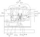
- FIG. 1is a view showing an electronic cigarette assembly according to an embodiment of the present invention
- FIG. 2is a cross-sectional view showing in detail the portable charging device of FIG.
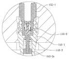
- FIG. 3is an enlarged view of 'III' of FIG. 2;
- Figure 4is a main part of the electronic cigarette body of Figure 1 is inserted into a portable charging device is a main part showing that the liquid
- FIG. 5is an enlarged view of 'V' of FIG. 4.
- the electronic cigarette assemblyaccording to an embodiment of the present invention, the electronic cigarette body, and a portable charging device 140.
- the electronic cigarette main bodyis composed of a suction unit (I), a power supply device 110, a combustion device 120, a liquid supply device 130 and a power button 139.
- the suction part (I), the through-hole (I-1)is formed in communication with the upper end of the flow pipe 113 to be described later may be screwed with the body 111 of the power supply device (110).
- the power supply device 110the upper end of the body 111 is coupled to the lower end of the suction unit (I), and to be supported through the fixed lead portion 112-1 in the interior of the body 111.
- the battery 112is installed, the flow path tube 113 for forming a flow path for discharging the vaporized gas inside the body 111, and is installed outside the body 111 and electrically connected to the battery 112 It comprises a connection terminal 114 connected to.
- connection terminal 114may be connected to the PCB substrate 114-1 that is received under the body 111, and may be connected to the battery 112 through the PCB substrate 114-1. .
- the combustion device 120the inner chamber 121 is screwed to the lower portion of the body 111, the coil is supported on the upper portion of the inner chamber 121 and electrically connected to the battery 111 and heatable coil And a wick 123 which is filled in the lower portion of the inner chamber 121 but partially contacts the coil 122.
- the inner chamber 121may have an upper end connected to a lower end of the flow pipe 113 to finally communicate with the through hole I-1 of the suction part I.
- the wick 123may be filled to effectively induce vaporization of the liquid phase.
- the wick 123, cotton wool or woolmay be used.
- the liquid supply device 130the main body 131 connected to the lower portion of the inner chamber 121, the liquid storage unit 132 provided inside the main body 131 to store the liquid, and the liquid storage A pair of level sensor units 133 and 134 installed inside the upper and lower portions of the unit 132 and the liquid supply unit 135 disposed at the center of the liquid storage unit 132 to receive liquid from the outside. It consists of.
- the liquid storage unit 132forms a liquid storage space, it is preferable that the interior is sealed.
- the pair of water level sensors 133 and 134may be connected to signal transmission cables 133-1 and 134-1 so as to transmit a signal to the lower end of the main body 131.
- the liquid supply unit 135is accommodated in the lower receiving groove 131a of the main body 131, the center of the upper and lower openings and the male coupler 135-1 communicating with the liquid storage unit 132, and the male coupler.
- the first rod 135-2for opening and closing the lower opening of the male coupler 135-1 so that the lower end partially protrudes from the lower portion of the male coupler 135-1, and the male coupler 135-1 of the male coupler 135-1.
- An upper opening and a lower portion of the inner chamber 121communicate with each other, and a wick is filled inward, and a plurality of through-holes 135-3a are formed on the inner side of the longitudinal direction.
- the first rod 135-2includes a fixing member 135-2a fixed near the inner center of the male coupler 135-1, and a coil spring 135 supported by the fixing member 135-2a. Elastically through -2b).
- the connecting pipe 135-3may have a lower portion engaged with an inner side of the male coupler 135-1, and an upper portion thereof is connected to a lower portion of the inner chamber 121 so that the wick provided at the inside thereof is the combustion.
- the wick 123 of the device 120is connected.
- the male coupler 135-1 and the first rod 135-2may be inclined to engage with each other.
- the electronic cigarette main bodymay be stored at a predetermined position of the first accommodating space part 141-2 of the portable charging device 140 at all times.
- the power button 139may be elastically pressed to vaporize the liquid phase, and may selectively energize the battery 112 and the coil 122 of the combustion device 120.
- the portable charging device 140as shown in Figures 1 to 3,
- a case 141having a liquid container 141-1 for accommodating a liquid phase and having a first accommodating space 141-2 configured to accommodate the electronic cigarette body therein;
- Pipe line 142-1for communicating the bottom of the liquid container 141-1 and the first accommodation space portion 141-2, and a pressure provided on the pipe line 142-1 to form a one-way flow path.
- a flow path controller 142composed of a pump 142-2;
- a female coupler (143-)is installed between the bottom of the first accommodating space (141-2) and the pipe (142-1) so that its center is opened up and down, and the upper portion of the male coupler (135-1) is accommodated therein. 1), a second rod 143-2 for elastically inserting an upper end portion of the female coupler 143-1 so as to partially protrude and opening and closing the middle portion of the female coupler 135-1, and the arm A liquid supply unit 143 configured to support the coupler 143-1 and support plates 143-3 elastically supported on the bottom of the first accommodation space 141-2; And
- the liquid control unit 144to control the liquid supply unit 143 to separate the male coupler (135-1) from the female coupler (143-1) when the liquid filling is completed.
- liquid supply cap 141-1amay be screwed to the upper end of the liquid container 141-1.
- the first accommodating space part 141-2 of the case 141is provided with a charging terminal 141-2b which may be in contact with the connection terminal 114, and accommodates the electronic cigarette body in the longitudinal direction thereof.
- Guide protrusions (141-2a)are provided for.
- the case 141 of the portable charging device 140may further include a second accommodation space portion 141-3 that accommodates the auxiliary battery assembly 150 connectable to the battery 112.
- the auxiliary battery assembly 150includes an auxiliary battery 151 and an input substrate 152 and an output substrate 153 which are disposed at upper and lower portions of the auxiliary battery 151 and connected to each other.
- the substrate 152is connected to the external charging terminal 152-1 and the display operation button 152-2 to the upper end of the case 141, and the output substrate 153 is connected to the charging terminal 141-2b. Electrically connected.
- the upper end of the case 141can be opened and closed through the hinge (H) cover 141-4, so that the remaining amount of the liquid stored in the liquid container (141-1) on the front outside
- the transparent unit 141-5is provided, and a display unit 141-6 for checking the voltage of the auxiliary battery assembly 150 is provided.
- the pressure pump 142-2 of the flow path controller 142operates when the electronic cigarette main body is accommodated in the first accommodating space 141-2 of the case 141 to fill the liquid phase ( The pressure plate is relaxed) to form a supply flow path in one direction on the pipe line 142-1. Conversely, when the pressure plate (not shown) is retracted, it is operated to interrupt the liquid supply.
- the female coupler 143-1 of the liquid supply part 143has a lower portion built into the bottom of the first accommodation space 141-2, and an intermediate portion and an upper portion of the female coupler 143-1 141-2. ) Is located inside.
- the second rod 143-2includes a fixing member 143-2a fixed near the inner center of the female coupler 143-1 and a coil spring 143 supported by the fixing member 143-2a. Elastically through -2b).
- the female coupler 143-1 and the second rod 143-2may be inclined to engage with each other.
- the support plate 143-3may be elastically supported through a coil spring 143-3a interposed between the bottom surface and the bottom of the first accommodation space 141-2.
- liquid phase control unit 144the liquid phase control unit 144
- a cylinder portion 144-2having a bar 144-2-1 installed inside the ball 144-1 and capable of supporting the ball 144-1, and
- First and second connection terminals 144-3 and 144-4provided on both sides of the support plate 143 and electrically connected to a pair of level sensor units 133 and 134, respectively;
- First and second detection sensors 144-5 and 144installed on the bottom surface of the first accommodation space 141-2 corresponding to the first and second connection terminals 144-3 and 144-4. -6) and,
- a switch unit 144-7electrically connected to the first and second detection sensors 144-5 and 144-6 to linearly move the bar 144-2-1 of the cylinder unit 144-2.
- Unexplained reference numeral 'C'is a check valve
- '141-7'is a coil storage portion
- '141-8'is a waterproof packing.
- the support plate 143-is supported by the elastic force of the coil spring 143-3a. 3) is located in the upper portion of the circumferential surface of the ball (144-1).
- the bar 144-2-1 of the cylinder 144-2is retracted (not spaced apart from the ball 144-1 to support the ball) by the signal of the switch 144-7.
- the flow path controller 142controls the pressure pump 142-2 to block the liquid supply through the pipe 142-1.
- the male coupler 135-1is inserted into the female coupler 143-1 to contact the first rod 135-2 and the second rod 143-2.
- the first and second rods 135-2 and 143-2are engaged by being moved by a predetermined distance in opposite directions while being elastically pressed together by the respective coil springs 135-2b and 143-2b.
- the gap between the male coupler 135-1 and the first rod 135-2 and the inclined surface between the female coupler 143-1 and the second rod 143-2is respectively generated. 1) A flow path communicating with each other is made inside 135-1.
- the flow path controller 142controls the pressure pump 142-2 to start the liquid phase supply through the pipe 142-1, and the male coupler 135-1 and the first rod 135-2. And the liquid is supplied in the direction of the connecting pipe (135-3) through the inclined surface between the female coupler (143-1) and the second rod (143-2).
- connection pipe (135-3)is filled with a wick to absorb the supplied liquid, and the absorbed liquid is stored in the liquid storage unit 132 through the plurality of through holes (135-3a).
- each signal transmission cable 133-1 or 134-1connected to the pair of level sensor units 133 and 134 and the first contacting unit
- the high water level signalis transmitted to the first and second detection sensors 144-5 and 144-6 through the second connection terminals 144-3 and 144-4.
- the switch unit 144-7controls the cylinder unit 144-2 to move (retreat) the bar 144-2-1 to the state shown in FIG. ) Is spaced apart from the ball 144-1, whereby the support plate 143-3 is lifted by the elastic force of the coil spring 143-3a to stop the liquid filling.
- the liquid phasemay be filled automatically, and charging through the auxiliary battery may be subsequently operated. That is, when the liquid phase filling is completed, the connection terminal 114 of the electronic cigarette main body may be in contact with the charging terminal 141-2b, thereby allowing the battery 112 to be charged through the auxiliary battery 151.
Landscapes
- Health & Medical Sciences (AREA)
- Engineering & Computer Science (AREA)
- Chemical & Material Sciences (AREA)
- Chemical Kinetics & Catalysis (AREA)
- General Chemical & Material Sciences (AREA)
- Biomedical Technology (AREA)
- Pulmonology (AREA)
- Anesthesiology (AREA)
- Bioinformatics & Cheminformatics (AREA)
- Heart & Thoracic Surgery (AREA)
- Hematology (AREA)
- Life Sciences & Earth Sciences (AREA)
- Animal Behavior & Ethology (AREA)
- General Health & Medical Sciences (AREA)
- Public Health (AREA)
- Veterinary Medicine (AREA)
- Charge And Discharge Circuits For Batteries Or The Like (AREA)
Abstract
Description
Translated fromKorean본 발명은 전자담배 어셈블리에 관한 것이다.The present invention relates to an electronic cigarette assembly.
일반적으로 전자담배는, 사용자가 흡입하기 위한 흡입부가 형성되고 상기 흡입부의 하부에 니코틴이 함유된 액상이 저장되는 저장부로 이루어진 카트리지와, 상기 카트리지의 저장부가 상단부에 내삽되도록 형성되되 상기 저장부의 액상을 연소시키도록 형성되는 무화기가 포함된 연소부와, 상기 연소부의 하단부에 결합되어 상기 무화기에 전원을 공급하도록 형성되는 전원공급부로 구성된다.In general, the electronic cigarette, a suction portion for the user to inhale is formed and the cartridge consisting of a storage unit for storing the liquid containing nicotine in the lower portion of the suction portion, the storage portion of the cartridge is formed so as to be inserted into the upper end of the liquid storage portion Combustion unit including an atomizer is formed to burn, and a power supply unit is coupled to the lower end of the combustion unit is formed to supply power to the atomizer.
이러한 전자담배는 일정시간 사용 후 전원공급부(배터리)의 하단에 형성된 충전단자에 별도의 충전기를 접속시켜 재충전하여 사용되는데, 외부 활동시 재충전이 필요할 경우를 대비해 충전기를 항시 휴대해야 하는 문제가 있고 충전시간 동안 대기해야 하는 문제가 있어 상당히 불편하였다.These e-cigarettes are used by recharging by connecting a separate charger to the charging terminal formed at the bottom of the power supply unit (battery) after a certain time of use. There was a problem of waiting for time, which was quite uncomfortable.
이를 해결하기 위해, 등록특허 제10-1498431호(등록일: 2015년2월25일)에는전자담배용 충전 어댑터 및 이를 이용한 충전장치가 개시되어 있다.To solve this problem, Patent No. 10-1498431 (Registration Date: February 25, 2015) discloses a charging adapter for an electronic cigarette and a charging device using the same.
등록특허 제10-1498431호의 구성에 의하면, 휴대용 배터리가 내장된 케이스 본체에 전자담배를 수납하면 전자담배에 구성된 배터리의 상시 충전이 이루어질 수 있도록 하고 있다.According to the configuration of Korean Patent No. 10-1498431, when the electronic cigarette is stored in the case body in which the portable battery is built, the battery configured in the electronic cigarette can be charged at all times.
그런데, 종래의 전자담배의 휴대용 충전장치에 의하면, 전자담배의 배터리 충전은 가능하나, 액상 충전 기능은 없어 액상 용기를 따로 휴대해야 하는 불편함이 있다.By the way, according to the conventional electronic cigarette portable charging device, it is possible to charge the battery of the electronic cigarette, but there is no inconvenience to carry a liquid container separately because there is no liquid filling function.
아울러, 액상은 사용자가 카트리지에 액상 용기의 입구부를 통해 직접 주입하는 방식으로 이루어짐으로써 사용편의성이 떨어지는 단점이 있다.In addition, the liquid phase has a disadvantage in that the user is made in such a way that the user directly injects through the inlet of the liquid container to the cartridge is less convenient.
본 발명은 상기한 문제점을 해결하기 위하여 창출된 것으로서, 전자담배의 액상을 편리하게 충전시킬 수 있는 전자담배 어셈블리를 제공하는데 그 목적이 있다.The present invention has been made to solve the above problems, and an object thereof is to provide an electronic cigarette assembly that can conveniently fill the liquid of the electronic cigarette.
또한, 본 발명은 전자담배의 액상을 자동으로 충전시킬 수 있는 전자담배 어셈블리를 제공하는데 그 목적이 있다.In addition, an object of the present invention is to provide an electronic cigarette assembly that can automatically fill the liquid of the electronic cigarette.
본 발명이 해결하고자 하는 과제는 이상에서 언급한 과제에 한정되지 않으며, 언급되지 않은 또 다른 과제는 아래의 기재로부터 당업자에게 명확하게 이해될 수 있을 것이다.The problem to be solved by the present invention is not limited to the above-mentioned problem, another problem that is not mentioned will be clearly understood by those skilled in the art from the following description.
상기한 목적을 달성하기 위해 본 발명의 일 측면에 따른 전자담배 어셈블리는,Electronic cigarette assembly according to an aspect of the present invention to achieve the above object,
상단에 흡입부가 체결되는 몸체와, 상기 몸체에 내장된 배터리로 구성된 전원공급장치;A power supply composed of a body coupled to the suction part at an upper end thereof, and a battery embedded in the body;
상기 몸체의 하부에 체결된 내실과, 상기 내실의 상부에 지지되며 상기 배터리에 전기적으로 접속되어 가열 가능한 코일과, 상기 내실의 하부에 채워지되 일부가 상기 코일에 접촉되는 심지로 구성된 연소장치; 및A combustion device comprising an inner chamber fastened to the lower portion of the body, a coil supported on the upper portion of the inner chamber and electrically connected to the battery and capable of being heated, and a wick filled in a lower portion of the inner chamber and partially contacting the coil; And
상기 내실의 하부에 연결된 본체와, 상기 본체의 내부에 마련되어 액상이 저장되는 액상 저장부와, 상기 액상 저장부의 상, 하측 내부에 설치되는 한 쌍의 수위센서부)와, 상기 액상 저장부의 중심으로 배치되어 액상을 공급받기 위한 액상공급부로 구성된 액상공급장치;를 포함하며,A main body connected to the lower part of the inner chamber, a liquid storage part provided inside the main body to store a liquid, a pair of water level sensor parts installed above and below the liquid storage part, and a center of the liquid storage part. Includes; is provided with a liquid supply device consisting of a liquid supply for receiving a liquid supply,
상기 액상공급부는,The liquid supply unit,
상기 본체의 하부에 수납되되 중심이 상하부 개구되어 상기 액상 저장부와 연통되는 숫커플러와, 상기 숫커플러의 하부에 하단이 일부 돌출되게 탄성 삽입되며 상기 숫커플러의 하부 개구부를 개폐하기 위한 제1로드와, 상기 숫커플러의 상부 개구부와 상기 내실의 하부를 연통시키되 내측에 심지가 채워지며 길이방향으로 복수의 관통공이 형성된 연결관으로 이루어지는 것을 특징으로 한다.The first coupler is accommodated in the lower portion of the main body, the upper and lower openings and the male coupler communicating with the liquid storage portion, the first rod for opening and closing the lower opening of the male coupler is elastically inserted so that the lower end partially protrudes in the lower portion of the male coupler And, the upper opening of the male coupler and the lower portion of the inner chamber is in communication with the wick is filled, characterized in that consisting of a connecting tube formed with a plurality of through holes in the longitudinal direction.
상기 전원공급장치는,The power supply device,
상기 몸체의 내부에 기화된 기체를 배출하기 위한 유로관을 더 포함하는 것을 특징으로 한다.It further comprises a flow path tube for discharging the gas vaporized in the interior of the body.
상기 흡입부의 하단과 상기 내실의 상단에는,At the lower end of the suction unit and the upper end of the inner chamber,
상기 유로관의 양단이 각각 연결되는 것을 특징으로 한다.Both ends of the flow pipe is characterized in that each connected.
상기 전원공급장치는,The power supply device,
상기 몸체의 외부에 설치되어 상기 배터리와 접속되는 접속단자를 더 포함하는 것을 특징으로 한다.It is characterized in that it further comprises a connection terminal installed outside the body and connected to the battery.
본 발명은,The present invention,
액상을 수용하기 위한 액통이 구비되며, 상기 전원공급장치, 상기 연소장치, 상기 액상공급장치가 일체로 된 상태로 내부에 수용할 수 있는 제1수용공간부가 형성된 케이스;A case provided with a liquid container for accommodating a liquid phase, the case having a first accommodating space part configured to be accommodated therein in a state in which the power supply device, the combustion device, and the liquid supply device are integrated;
상기 액통과 상기 제1수용공간부의 저부를 연통시키는 관로와, 상기 관로 상에 설치되어 일 방향 유로를 형성시키는 압력펌프로 구성되는 유로제어부; 및A flow path control unit including a conduit for communicating the liquid container with a bottom of the first accommodating space, and a pressure pump installed on the conduit to form a one-way flow path; And
상기 제1수용공간부의 저부와 상기 관로 사이에 중심이 상하부 개구되도록 설치되되 상부에 상기 숫커플러의 하부가 수용 가능한 암커플러와, 상기 암커플러의 중간부에 상단이 일부 돌출되게 탄성 삽입되며 상기 암커플러의 중간부를 개폐하기 위한 제2로드와, 상기 암커플러가 관통되며 상기 제1수용공간부의 바닥에 탄성지지되는 지지플레이트로 구성된 액상공급부;A female coupler is installed between the bottom of the first accommodating space and the conduit so that a center thereof is opened up and down, the female coupler having a lower portion of the male coupler disposed therein, and an upper portion of the female coupler protruding from the female coupler. A liquid supply unit including a second rod for opening and closing the middle of the coupler, and a support plate through which the female coupler penetrates and is elastically supported on the bottom of the first accommodation space;
를 포함하는 휴대용 충전장치를 더 포함하는 것을 특징으로 한다.Characterized in that it further comprises a portable charging device comprising a.
상기 휴대용 충전장치는,The portable charging device,
상기 제1수용공간부의 하부 원주면의 일정 높이에 탄성지게 내설되는 적어도 하나의 볼과,At least one ball elastically housed at a predetermined height of the lower circumferential surface of the first accommodation space;
상기 볼의 내측에 설치되어 상기 볼을 지지할 수 있는 바아가 구비된 실린더부와,A cylinder part provided at an inner side of the ball and having a bar capable of supporting the ball;
상기 지지플레이트의 양측에 각각 설치되어 한 쌍의 수위센서부와 각각 전기적으로 연결 가능한 제1,2연결단자와,First and second connection terminals respectively provided at both sides of the support plate and electrically connected to a pair of level sensor units;
상기 제1,2연결단자와 대응하는 상기 제1수용공간부의 바닥에 설치되는 제1,2감지센서와,First and second detection sensors installed on a bottom of the first accommodation space corresponding to the first and second connection terminals;
상기 제1,2감지센서와 전기적으로 연결되어 상기 실린더부의 바아를 작동시키기 위한 스위치부A switch unit electrically connected to the first and second detection sensors to operate the cylinder bar;
를 포함하는 액상제어부;를 더 포함하는 것을 특징으로 한다.It characterized in that it further comprises; liquid control unit comprising a.
상기 휴대용 충전장치의 케이스에는,In the case of the portable charging device,
상기 배터리와 접속 가능한 보조배터리조립체가 수용되는 제2수용공간부가 더 형성되는 것을 특징으로 한다.A second accommodating space portion for accommodating the auxiliary battery assembly connectable to the battery may be further formed.
전술한 바와 같이 본 발명에 따른 전자담배 어셈블리에 의하면, 액상공급장치를 포함함으로써 액상을 편리하게 충전시킬 수 있는 장점이 있다.According to the electronic cigarette assembly according to the present invention as described above, there is an advantage that the liquid phase can be conveniently filled by including the liquid supply device.
또한, 본 발명에 따른 전자담배 어셈블리에 의하면, 휴대용 충전장치에 상기 전자담배 본체를 수납하면 배터리와 액상을 자동으로 충전시킬 수 있어 사용편의성을 향상시킬 수 있다.In addition, according to the electronic cigarette assembly according to the present invention, by storing the electronic cigarette main body in a portable charging device it is possible to automatically charge the battery and the liquid can improve the ease of use.
도 1은 본 발명의 일 실시예에 따른 전자담배 어셈블리를 보인 도면,1 is a view showing an electronic cigarette assembly according to an embodiment of the present invention,
도 2는 도 1의 휴대용 충전장치를 상세히 보인 단면도,2 is a cross-sectional view showing in detail the portable charging device of FIG.
도 3은 도 2의 'Ⅲ'을 확대해서 보인 도면,3 is an enlarged view of 'III' of FIG. 2;
도 4는 도 1의 전자담배 본체가 휴대용 충전장치에 삽입되어 액상이 충전되는 것을 보인 요부 도면 및Figure 4 is a main part of the electronic cigarette body of Figure 1 is inserted into a portable charging device is a main part showing that the liquid
도 5는 도 4의 'Ⅴ'을 확대해서 보인 도면이다.FIG. 5 is an enlarged view of 'V' of FIG. 4.
이하, 첨부된 도면을 참조로 본 발명의 일 실시예에 따른 전자담배 어셈블리에 대해 상세하게 살펴본다.Hereinafter, with reference to the accompanying drawings looks at in detail with respect to the electronic cigarette assembly according to an embodiment of the present invention.
이에 앞서, 본 명세서 및 청구범위에 사용된 용어나 단어는 통상적이거나 사전적인 의미로 한정해서 해석되어서는 아니 되며, 발명자는 그 자신의 발명을 가장 최선의 방법으로 설명하기 위해 용어의 개념을 적절하게 정의할 수 있다는 원칙에 입각하여 본 발명의 기술적 사상에 부합하는 의미와 개념으로 해석되어야만 한다.Prior to this, terms or words used in the present specification and claims should not be construed as being limited to the common or dictionary meanings, and the inventors should properly explain the concept of terms in order to best explain their own invention. Based on the principle that can be defined, it should be interpreted as meaning and concept corresponding to the technical idea of the present invention.
따라서, 본 명세서에 기재된 실시예와 도면에 도시된 구성은 본 발명의 가장 바람직한 일 실시예에 불과할 뿐이고, 본 발명의 기술적 사상을 모두 대변하는 것은 아니므로, 본 출원시점에 있어서 이들은 대체할 수 있는 다양한 균등물과 변형예들이 있을 수 있음을 이해하여야 한다.Therefore, the embodiments described in the specification and the configuration shown in the drawings are only the most preferred embodiment of the present invention, and do not represent all of the technical idea of the present invention, these can be replaced at the time of the present application It should be understood that there may be various equivalents and variations.
도 1 및 도 2에 도시된 바와 같이, 본 발명의 일 실시예에 따른 전자담배 어셈블리는, 전자담배 본체와, 휴대용 충전장치(140)를 포함한다.As shown in Figure 1 and 2, the electronic cigarette assembly according to an embodiment of the present invention, the electronic cigarette body, and a
상기 전자담배 본체는, 흡입부(I)와, 전원공급장치(110)와, 연소장치(120)와, 액상공급장치(130) 및 전원버튼(139)으로 구성된다.The electronic cigarette main body is composed of a suction unit (I), a
여기서, 상기 흡입부(I)에는, 후술할 유로관(113)의 상단과 연통되는 통공(I-1)이 형성되어 상기 전원공급장치(110)의 몸체(111)와 나사 결합될 수 있다.Here, the suction part (I), the through-hole (I-1) is formed in communication with the upper end of the
또한, 상기 전원공급장치(110)는, 상단에 상기 흡입부(I)의 하단이 결합되는 몸체(111)와, 상기 몸체(111)의 내부에 고정리드부(112-1)를 통해 지지되게 설치된 배터리(112)와, 상기 몸체(111)의 내부에 기화된 기체를 배출하기 위한 유로를 형성하는 유로관(113)과, 상기 몸체(111)의 외부에 설치되어 상기 배터리(112)와 전기적으로 연결되는 접속단자(114)를 포함하여 이루어진다.In addition, the
이때, 상기 접속단자(114)는 상기 몸체(111)의 하부에 수납되는 PCB기판(114-1)에 연결되며, 이 PCB기판(114-1)을 통해 상기 배터리(112)와 접속될 수 있다.In this case, the
또한, 상기 연소장치(120)는, 상기 몸체(111)의 하부에 나사결합되는 내실(121)과, 상기 내실(121)의 상부에 지지되며 상기 배터리(111)에 전기적으로 접속되어 가열 가능한 코일(122)과, 상기 내실(121)의 하부에 채워지되 일부가 상기 코일(122)에 접촉되는 심지(123)로 구성된다.In addition, the combustion device 120, the inner chamber 121 is screwed to the lower portion of the
이때, 상기 내실(121)은 그 상단이 상기 유로관(113)의 하단이 연결되어 최종적으로 상기 흡입부(I)의 통공(I-1)과 연통될 수 있다.In this case, the inner chamber 121 may have an upper end connected to a lower end of the
상기 코일(122)의 내부에는, 미도시하였으나 액상의 기화를 효과적으로 유도하기 위해 상기 심지(123)가 채워짐이 바람직하다.Although not shown in the
상기 심지(123)는, 목화솜이나 양모 등이 이용될 수 있다.The
아울러, 상기 액상공급장치(130)는, 상기 내실(121)의 하부에 연결된 본체(131)와, 상기 본체(131)의 내부에 마련되어 액상이 저장되는 액상 저장부(132)와, 상기 액상 저장부(132)의 상, 하측 내부에 설치되는 한 쌍의 수위센서부(133)(134)와, 상기 액상 저장부(132)의 중심으로 배치되어 외부로부터 액상을 공급받기 위한 액상공급부(135)로 구성된다.In addition, the
이때, 상기 본체(131)의 하부에는, 상기 액상공급부(135)를 설치하기 위한 수용홈(131a)이 형성된다.At this time, the lower portion of the
상기 액상 저장부(132)는, 액상저장공간을 형성하며, 내부가 밀폐됨이 바람직하다.The
상기 한 쌍의 수위센서부(133)(134)는, 상기 본체(131)의 하단으로 신호를 전달할 수 있도록 신호전달케이블(133-1)(134-1)이 각각 연결될 수 있다.The pair of
상기 액상공급부(135)는, 상기 본체(131)의 하부 수용홈(131a)에 수납되되 중심이 상하부 개구되어 상기 액상 저장부(132)와 연통되는 숫커플러(135-1)와, 상기 숫커플러(135-1)의 하부에 하단이 일부 돌출되게 탄성 삽입되며 상기 숫커플러(135-1)의 하부 개구부를 개폐하기 위한 제1로드(135-2)와, 상기 숫커플러(135-1)의 상부 개구부와 상기 내실(121)의 하부를 연통시키되 내측에 심지가 채워지며 길이방향 중심부 측으로 복수의 관통공(135-3a)이 형성된 연결관(135-3)으로 이루어진다.The
상기 제1로드(135-2)는, 상기 숫커플러(135-1)의 내측 중심 부근에 고정된 고정부재(135-2a)와, 상기 고정부재(135-2a)에 지지된 코일스프링(135-2b)을 통해 탄성적으로 설치된다.The first rod 135-2 includes a fixing member 135-2a fixed near the inner center of the male coupler 135-1, and a
상기 연결관(135-3)은, 그 하부가 상기 숫커플러(135-1)의 내측에 맞물림 결합될 수 있으며, 상부는 상기 내실(121)의 하부에 연결되어 내측에 구비되는 심지가 상기 연소장치(120)의 심지(123)와 이어진다.The connecting pipe 135-3 may have a lower portion engaged with an inner side of the male coupler 135-1, and an upper portion thereof is connected to a lower portion of the inner chamber 121 so that the wick provided at the inside thereof is the combustion. The
상기 숫커플러(135-1)와 상기 제1로드(135-2)에는, 각각 경사면이 형성되어 맞물림될 수 있다.The male coupler 135-1 and the first rod 135-2 may be inclined to engage with each other.
아울러, 상기 몸체(111)와 상기 내실(121) 및 상기 본체(131)에는, 미도시한 가이드홈이 형성되어 후술할 상기 휴대용 충전장치(140)의 제1수용공간부(141-2)에 형성된 가이드돌기(141-2a)와 대응하여 상기 전자담배 본체를 항상 상기 휴대용 충전장치(140)의 제1수용공간부(141-2)의 정 위치에 수납시킬 수 있다.In addition, the
또한, 상기 전원버튼(139)은, 액상을 기화시키기 위해 탄성 누름 가능하며, 상기 배터리(112)와 상기 연소장치(120)의 코일(122)을 선택적으로 통전시킬 수 있다.In addition, the
한편, 상기 휴대용 충전장치(140)는, 도 1 내지 도 3에 도시된 바와 같이,On the other hand, the
액상을 수용하기 위한 액통(141-1)이 구비되며, 상기 전자담배 본체를 내부에 수용할 수 있는 제1수용공간부(141-2)가 형성된 케이스(141);A
상기 액통(141-1)과 상기 제1수용공간부(141-2)의 저부를 연통시키는 관로(142-1)와, 상기 관로(142-1) 상에 설치되어 일 방향 유로를 형성시키는 압력펌프(142-2)로 구성되는 유로제어부(142);Pipe line 142-1 for communicating the bottom of the liquid container 141-1 and the first accommodation space portion 141-2, and a pressure provided on the pipe line 142-1 to form a one-way flow path. A
상기 제1수용공간부(141-2)의 저부와 상기 관로(142-1) 사이에 중심이 상하부 개구되도록 설치되되 상부에 상기 숫커플러(135-1)의 하부가 수용 가능한 암커플러(143-1)와, 상기 암커플러(143-1)의 중간부에 상단이 일부 돌출되게 탄성 삽입되며 상기 암커플러(135-1)의 중간부를 개폐하기 위한 제2로드(143-2)와, 상기 암커플러(143-1)가 관통되며 상기 제1수용공간부(141-2)의 바닥에 탄성지지되는 지지플레이트(143-3)로 구성된 액상공급부(143); 및A female coupler (143-) is installed between the bottom of the first accommodating space (141-2) and the pipe (142-1) so that its center is opened up and down, and the upper portion of the male coupler (135-1) is accommodated therein. 1), a second rod 143-2 for elastically inserting an upper end portion of the female coupler 143-1 so as to partially protrude and opening and closing the middle portion of the female coupler 135-1, and the arm A
상기 액상공급부(143)를 제어하여 액상충전 완료시 상기 암커플러(143-1)로부터 상기 숫커플러(135-1)를 이격시키는 액상제어부(144);로 구성된다.The
여기서, 상기 액통(141-1)의 상단에는, 액상 공급용 뚜껑(141-1a)이 나사 결합될 수 있다.Here, the liquid supply cap 141-1a may be screwed to the upper end of the liquid container 141-1.
상기 케이스(141)의 제1수용공간부(141-2)에는, 상기 접속단자(114)와 접촉될 수 있는 충전단자(141-2b)가 마련되며, 그 길이방향으로 전자담배 본체를 수용하기 위한 가이드돌기(141-2a)가 마련된다.The first accommodating space part 141-2 of the
상기 휴대용 충전장치(140)의 케이스(141)에는, 상기 배터리(112)와 접속 가능한 보조배터리조립체(150)가 수용되는 제2수용공간부(141-3)가 더 형성될 수 있다. 구체적으로, 상기 보조배터리조립체(150)는, 보조배터리(151)와, 상기 보조배터리(151)의 상하부에 배치되어 각각 접속되는 입력기판(152)과 출력기판(153)으로 구성되는데, 상기 입력기판(152)은 상기 케이스(141)의 상단으로 외부충전단자(152-1) 및 디스플레이작동버튼(152-2)과 각각 연결되며, 상기 출력기판(153)은 충전단자(141-2b)와 전기적으로 연결된다.The
또한, 상기 케이스(141)의 상단은, 힌지(H) 결합되는 덮개(141-4)를 통해 개폐될 수 있으며, 전면 외부에는 상기 액통(141-1)에 보관한 액상의 잔량을 확인할 수 있도록 투명부(141-5)가 구비되며, 상기 보조배터리조립체(150)의 전압을 체크하기 위한 디스플레이부(141-6)가 구비된다.In addition, the upper end of the
상기 유로제어부(142)의 압력펌프(142-2)는, 상기 전자담배 본체가 상기 케이스(141)의 제1수용공간부(141-2)에 수용되어 액상을 충전할 경우에 작동(내부의 압력판이 이완)되며, 상기 관로(142-1) 상에 일방향의 공급 유로를 형성하게 된다. 반대로 압력판(도시 생략)이 수축되면, 액상 공급을 차단시키도록 작동된다.The pressure pump 142-2 of the
상기 액상공급부(143)의 암커플러(143-1)는, 하부가 상기 제1수용공간부(141-2)의 바닥에 내설되고, 중간부와 상부는 상기 제1수용공간부(141-2)의 내측에 위치하게 된다.The female coupler 143-1 of the
상기 제2로드(143-2)는, 상기 암커플러(143-1)의 내측 중심 부근에 고정된 고정부재(143-2a)와, 상기 고정부재(143-2a)에 지지된 코일스프링(143-2b)을 통해 탄성적으로 설치된다.The second rod 143-2 includes a fixing member 143-2a fixed near the inner center of the female coupler 143-1 and a
이들 상기 암커플러(143-1)와 상기 제2로드(143-2)에는, 각각 경사면이 형성되어 서로 맞물림될 수 있다.The female coupler 143-1 and the second rod 143-2 may be inclined to engage with each other.
상기 지지플레이트(143-3)는, 그 하면과 상기 제1수용공간부(141-2)의 바닥 사이에 개제되는 코일스프링(143-3a)을 매개로 탄성지지될 수 있다.The support plate 143-3 may be elastically supported through a coil spring 143-3a interposed between the bottom surface and the bottom of the first accommodation space 141-2.
한편, 상기 액상제어부(144)는,On the other hand, the liquid
상기 제1수용공간부(141-2)의 하부 원주면의 일정 높이에 형성된 홈부(144a)에 탄성지게 내설되는 적어도 하나의 볼(144-1)과,At least one ball 144-1 elastically embedded in the
상기 볼(144-1)의 내측에 설치되어 상기 볼(144-1)을 지지할 수 있는 바아(144-2-1)가 내설된 실린더부(144-2)와,A cylinder portion 144-2 having a bar 144-2-1 installed inside the ball 144-1 and capable of supporting the ball 144-1, and
상기 지지플레이트(143)의 양측에 각각 설치되어 한 쌍의 수위센서부(133)(134)와 각각 전기적으로 연결 가능한 제1,2연결단자(144-3)(144-4)와,First and second connection terminals 144-3 and 144-4 provided on both sides of the
상기 제1,2연결단자(144-3)(144-4)와 대응하는 상기 제1수용공간부(141-2)의 바닥면에 설치되는 제1,2감지센서(144-5)(144-6)와,First and second detection sensors 144-5 and 144 installed on the bottom surface of the first accommodation space 141-2 corresponding to the first and second connection terminals 144-3 and 144-4. -6) and,
상기 제1,2감지센서(144-5)(144-6)와 전기적으로 연결되어 상기 실린더부(144-2)의 바아(144-2-1)를 직선운동시키기 위한 스위치부(144-7)로 이루어진다.A switch unit 144-7 electrically connected to the first and second detection sensors 144-5 and 144-6 to linearly move the bar 144-2-1 of the cylinder unit 144-2. )
미설명된 도면부호인 'C'는 체크밸브이고, '141-7'은 코일 보관부를 나타낸 것이며, '141-8'은 방수패킹을 나타낸 것이다.Unexplained reference numeral 'C' is a check valve, '141-7' is a coil storage portion, '141-8' is a waterproof packing.
이하, 도면을 참조하여 상술한 본 발명 전자담배 어셈블리의 작용에 대해 살펴본다.Hereinafter, with reference to the drawings looks at the operation of the above-described electronic cigarette assembly of the present invention.
도 3에 보이듯이, 전자담배 본체가 휴대용 충전장치(140)의 제1수용공간부(141-2)에 수용되지 않은 경우에는, 코일스프링(143-3a)의 탄성력에 의해 지지플레이트(143-3)가 볼(144-1) 원주면의 윗부분에 위치하게 된다. 이때는 스위치부(144-7)의 신호에 의해 실린더부(144-2)의 바아(144-2-1)가 후퇴(볼(144-1)과 이격되어 볼을 지지하지 않는)된 상태로 있으며, 유로제어부(142)는 압력펌프(142-2)를 제어하여 관로(142-1)를 통한 액상 공급을 차단하게 된다.As shown in FIG. 3, when the electronic cigarette main body is not accommodated in the first accommodating space 141-2 of the
반면, 도 4 및 도 5에 보인 바와 같이, 전자담배 본체가 휴대용 충전장치(140)의 제1수용공간부(141-2)에 수용될 경우, 사용자가 누르는 힘에 의해 코일스프링(143-3a)이 압축되면서 지지플레이트(143-3)가 화살표 방향 하측으로 이동되어 볼(144-1) 원주면의 아랫부분에 위치하게 된다.On the other hand, as shown in Figures 4 and 5, when the electronic cigarette body is accommodated in the first receiving space portion (141-2) of the
이와 동시에 암커플러(143-1)의 내측으로 숫커플러(135-1)가 삽입되어 제1로드(135-2)와 제2로드(143-2)가 접촉된다. 이때, 제1,2로드(135-2)(143-2)가 각각의 코일스프링(135-2b)(143-2b)에 의해 서로 탄성적으로 눌리면서 서로 반대방향으로 소정거리 이동됨으로써 맞물려져 있던 숫커플러(135-1)와 제1로드(135-2) 그리고 암커플러(143-1)와 제2로드(143-2) 사이의 경사면에 각각 유격이 발생되고, 암,숫커플러(143-1)(135-1)의 내측으로 서로 통하는 유로가 만들어진다.At the same time, the male coupler 135-1 is inserted into the female coupler 143-1 to contact the first rod 135-2 and the second rod 143-2. At this time, the first and second rods 135-2 and 143-2 are engaged by being moved by a predetermined distance in opposite directions while being elastically pressed together by the respective coil springs 135-2b and 143-2b. The gap between the male coupler 135-1 and the first rod 135-2 and the inclined surface between the female coupler 143-1 and the second rod 143-2 is respectively generated. 1) A flow path communicating with each other is made inside 135-1.
유로가 형성되면, 유로제어부(142)는 압력펌프(142-2)를 제어하여 관로(142-1)를 통한 액상 공급을 시작하며, 숫커플러(135-1)와 제1로드(135-2) 그리고 암커플러(143-1)와 제2로드(143-2) 사이의 경사면을 통해 연결관(135-3) 방향으로 액상을 공급하게 된다.When the flow path is formed, the
이때, 연결관(135-3)의 내측에는 심지가 채워져 있어 공급되는 액상을 흡수하며, 흡수된 액상은 복수의 관통공(135-3a)을 통해 액상 저장부(132)로 빠져나가 저장된다.At this time, the inside of the connection pipe (135-3) is filled with a wick to absorb the supplied liquid, and the absorbed liquid is stored in the
만약, 액상 저장부(132)에 저장되는 액상이 만수위가 되면 한 쌍의 수위센서부(133)(134)와 연결된 각 신호전달케이블(133-1)(134-1)과 이에 접촉된 제1,2연결단자(144-3)(144-4)를 통해 제1,2감지센서(144-5)(144-6)로 만수위 신호를 보내주게 된다.If the liquid phase stored in the
만수위 신호에 따라, 스위치부(144-7)는 실린더부(144-2)를 제어하여 바아(144-2-1)를 도 3의 상태로 이동(후퇴)시키게 되어 바아(144-2-1)를 볼(144-1)과 이격시키는데, 이에 따라서 지지플레이트(143-3)는 코일스프링(143-3a)의 탄성력에 의해 상승하여 액상 충전이 멈추는 것이다.In response to the high water level signal, the switch unit 144-7 controls the cylinder unit 144-2 to move (retreat) the bar 144-2-1 to the state shown in FIG. ) Is spaced apart from the ball 144-1, whereby the support plate 143-3 is lifted by the elastic force of the coil spring 143-3a to stop the liquid filling.
이와 같이, 전자담배 본체가 휴대용 충전장치(140)의 제1수용공간부(141-2)에 수용되면 자동으로 액상이 만충될 수 있으며, 보조배터리를 통한 충전은 뒤이어 작동될 수 있도록 할 수 있다. 즉, 액상 충전이 완료될 때 충전단자(141-2b)에 전자담배 본체의 접속단자(114)가 접촉될 수 있도록 하여 보조배터리(151)를 통한 배터리(112)의 충전이 가능하게 된다.As such, when the electronic cigarette body is accommodated in the first accommodating space portion 141-2 of the
이상과 같이, 본 발명은 비록 한정된 실시예와 도면에 의해 설명되었으나 이에 한정되지 않으며, 발명이 속하는 기술분야에서 통상의 지식을 가진 자에 의해 본 발명의 기술 사상과 아래에 기재될 청구범위의 균등범위 내에서 다양한 수정 및 변형 가능함은 물론이다.As described above, although the present invention has been described by way of limited embodiments and drawings, the present invention is not limited thereto, and the technical spirit of the present invention and the equivalents of the claims to be described below by those skilled in the art to which the invention pertains. Of course, various modifications and variations are possible within the scope.
Claims (7)
Translated fromKoreanApplications Claiming Priority (2)
| Application Number | Priority Date | Filing Date | Title |
|---|---|---|---|
| KR1020160033184AKR101654901B1 (en) | 2016-03-21 | 2016-03-21 | Eletronic cigarette assembly |
| KR10-2016-0033184 | 2016-03-21 |
Publications (1)
| Publication Number | Publication Date |
|---|---|
| WO2017164474A1true WO2017164474A1 (en) | 2017-09-28 |
Family
ID=56946314
Family Applications (1)
| Application Number | Title | Priority Date | Filing Date |
|---|---|---|---|
| PCT/KR2016/011145CeasedWO2017164474A1 (en) | 2016-03-21 | 2016-10-05 | Electronic cigarette assembly |
Country Status (2)
| Country | Link |
|---|---|
| KR (1) | KR101654901B1 (en) |
| WO (1) | WO2017164474A1 (en) |
Cited By (19)
| Publication number | Priority date | Publication date | Assignee | Title |
|---|---|---|---|---|
| USD825102S1 (en) | 2016-07-28 | 2018-08-07 | Juul Labs, Inc. | Vaporizer device with cartridge |
| US10045568B2 (en) | 2013-12-23 | 2018-08-14 | Juul Labs, Inc. | Vaporization device systems and methods |
| US10045567B2 (en) | 2013-12-23 | 2018-08-14 | Juul Labs, Inc. | Vaporization device systems and methods |
| US10058130B2 (en) | 2013-12-23 | 2018-08-28 | Juul Labs, Inc. | Cartridge for use with a vaporizer device |
| US10076139B2 (en) | 2013-12-23 | 2018-09-18 | Juul Labs, Inc. | Vaporizer apparatus |
| US10104915B2 (en) | 2013-12-23 | 2018-10-23 | Juul Labs, Inc. | Securely attaching cartridges for vaporizer devices |
| US10111470B2 (en) | 2013-12-23 | 2018-10-30 | Juul Labs, Inc. | Vaporizer apparatus |
| USD836541S1 (en) | 2016-06-23 | 2018-12-25 | Pax Labs, Inc. | Charging device |
| USD842536S1 (en) | 2016-07-28 | 2019-03-05 | Juul Labs, Inc. | Vaporizer cartridge |
| US10244793B2 (en) | 2005-07-19 | 2019-04-02 | Juul Labs, Inc. | Devices for vaporization of a substance |
| US10279934B2 (en) | 2013-03-15 | 2019-05-07 | Juul Labs, Inc. | Fillable vaporizer cartridge and method of filling |
| USD849996S1 (en) | 2016-06-16 | 2019-05-28 | Pax Labs, Inc. | Vaporizer cartridge |
| USD851830S1 (en) | 2016-06-23 | 2019-06-18 | Pax Labs, Inc. | Combined vaporizer tamp and pick tool |
| US10405582B2 (en) | 2016-03-10 | 2019-09-10 | Pax Labs, Inc. | Vaporization device with lip sensing |
| WO2019237986A1 (en)* | 2018-06-12 | 2019-12-19 | 常州市派腾电子技术服务有限公司 | Liquid supply assembly, power supply device and electronic cigarette |
| US10512282B2 (en) | 2014-12-05 | 2019-12-24 | Juul Labs, Inc. | Calibrated dose control |
| USD887632S1 (en) | 2017-09-14 | 2020-06-16 | Pax Labs, Inc. | Vaporizer cartridge |
| US10701976B2 (en) | 2016-12-12 | 2020-07-07 | VMR Products, LLC | Vaporizer cartridge |
| US10865001B2 (en) | 2016-02-11 | 2020-12-15 | Juul Labs, Inc. | Fillable vaporizer cartridge and method of filling |
Families Citing this family (3)
| Publication number | Priority date | Publication date | Assignee | Title |
|---|---|---|---|---|
| KR102401552B1 (en)* | 2019-06-20 | 2022-05-24 | 주식회사 케이티앤지 | Cartridge for preventing leakage and an aerosol generating device including the same |
| KR102330305B1 (en)* | 2019-08-07 | 2021-11-24 | 주식회사 케이티앤지 | Cartridge and Aerosol generating device including the same |
| KR20230052172A (en)* | 2021-10-12 | 2023-04-19 | 주식회사 이노아이티 | Metal fiber plane heater for aerosol generator |
Citations (5)
| Publication number | Priority date | Publication date | Assignee | Title |
|---|---|---|---|---|
| KR20120104183A (en)* | 2009-09-16 | 2012-09-20 | 필립모리스 프로덕츠 에스.에이. | Improved device and method for delivery of a medicament |
| KR101387801B1 (en)* | 2013-09-12 | 2014-04-21 | 박선순 | Electronic cigarette with the pressure chamber type |
| KR20140135774A (en)* | 2012-02-22 | 2014-11-26 | 알트리아 클라이언트 서비시스 인코포레이티드 | Electronic smoking article and improved heater element |
| KR20160012111A (en)* | 2013-03-15 | 2016-02-02 | 알트리아 클라이언트 서비시즈 엘엘씨 | Electronic smoking article |
| KR20160016989A (en)* | 2016-01-22 | 2016-02-15 | 황일영 | Atomizer |
- 2016
- 2016-03-21KRKR1020160033184Apatent/KR101654901B1/ennot_activeExpired - Fee Related
- 2016-10-05WOPCT/KR2016/011145patent/WO2017164474A1/ennot_activeCeased
Patent Citations (5)
| Publication number | Priority date | Publication date | Assignee | Title |
|---|---|---|---|---|
| KR20120104183A (en)* | 2009-09-16 | 2012-09-20 | 필립모리스 프로덕츠 에스.에이. | Improved device and method for delivery of a medicament |
| KR20140135774A (en)* | 2012-02-22 | 2014-11-26 | 알트리아 클라이언트 서비시스 인코포레이티드 | Electronic smoking article and improved heater element |
| KR20160012111A (en)* | 2013-03-15 | 2016-02-02 | 알트리아 클라이언트 서비시즈 엘엘씨 | Electronic smoking article |
| KR101387801B1 (en)* | 2013-09-12 | 2014-04-21 | 박선순 | Electronic cigarette with the pressure chamber type |
| KR20160016989A (en)* | 2016-01-22 | 2016-02-15 | 황일영 | Atomizer |
Cited By (34)
| Publication number | Priority date | Publication date | Assignee | Title |
|---|---|---|---|---|
| US10244793B2 (en) | 2005-07-19 | 2019-04-02 | Juul Labs, Inc. | Devices for vaporization of a substance |
| US10638792B2 (en) | 2013-03-15 | 2020-05-05 | Juul Labs, Inc. | Securely attaching cartridges for vaporizer devices |
| US10279934B2 (en) | 2013-03-15 | 2019-05-07 | Juul Labs, Inc. | Fillable vaporizer cartridge and method of filling |
| US10117465B2 (en) | 2013-12-23 | 2018-11-06 | Juul Labs, Inc. | Vaporization device systems and methods |
| US10264823B2 (en) | 2013-12-23 | 2019-04-23 | Juul Labs, Inc. | Vaporization device systems and methods |
| US10058130B2 (en) | 2013-12-23 | 2018-08-28 | Juul Labs, Inc. | Cartridge for use with a vaporizer device |
| US10070669B2 (en) | 2013-12-23 | 2018-09-11 | Juul Labs, Inc. | Cartridge for use with a vaporizer device |
| US10076139B2 (en) | 2013-12-23 | 2018-09-18 | Juul Labs, Inc. | Vaporizer apparatus |
| US10104915B2 (en) | 2013-12-23 | 2018-10-23 | Juul Labs, Inc. | Securely attaching cartridges for vaporizer devices |
| US10111470B2 (en) | 2013-12-23 | 2018-10-30 | Juul Labs, Inc. | Vaporizer apparatus |
| US11752283B2 (en) | 2013-12-23 | 2023-09-12 | Juul Labs, Inc. | Vaporization device systems and methods |
| US10117466B2 (en) | 2013-12-23 | 2018-11-06 | Juul Labs, Inc. | Vaporization device systems and methods |
| US10912331B2 (en) | 2013-12-23 | 2021-02-09 | Juul Labs, Inc. | Vaporization device systems and methods |
| US10159282B2 (en) | 2013-12-23 | 2018-12-25 | Juul Labs, Inc. | Cartridge for use with a vaporizer device |
| US10201190B2 (en) | 2013-12-23 | 2019-02-12 | Juul Labs, Inc. | Cartridge for use with a vaporizer device |
| US10701975B2 (en) | 2013-12-23 | 2020-07-07 | Juul Labs, Inc. | Vaporization device systems and methods |
| US10045568B2 (en) | 2013-12-23 | 2018-08-14 | Juul Labs, Inc. | Vaporization device systems and methods |
| US10058124B2 (en) | 2013-12-23 | 2018-08-28 | Juul Labs, Inc. | Vaporization device systems and methods |
| US10045567B2 (en) | 2013-12-23 | 2018-08-14 | Juul Labs, Inc. | Vaporization device systems and methods |
| US10667560B2 (en) | 2013-12-23 | 2020-06-02 | Juul Labs, Inc. | Vaporizer apparatus |
| US10058129B2 (en) | 2013-12-23 | 2018-08-28 | Juul Labs, Inc. | Vaporization device systems and methods |
| US10512282B2 (en) | 2014-12-05 | 2019-12-24 | Juul Labs, Inc. | Calibrated dose control |
| US10865001B2 (en) | 2016-02-11 | 2020-12-15 | Juul Labs, Inc. | Fillable vaporizer cartridge and method of filling |
| US10405582B2 (en) | 2016-03-10 | 2019-09-10 | Pax Labs, Inc. | Vaporization device with lip sensing |
| USD929036S1 (en) | 2016-06-16 | 2021-08-24 | Pax Labs, Inc. | Vaporizer cartridge and device assembly |
| USD849996S1 (en) | 2016-06-16 | 2019-05-28 | Pax Labs, Inc. | Vaporizer cartridge |
| USD913583S1 (en) | 2016-06-16 | 2021-03-16 | Pax Labs, Inc. | Vaporizer device |
| USD836541S1 (en) | 2016-06-23 | 2018-12-25 | Pax Labs, Inc. | Charging device |
| USD851830S1 (en) | 2016-06-23 | 2019-06-18 | Pax Labs, Inc. | Combined vaporizer tamp and pick tool |
| USD842536S1 (en) | 2016-07-28 | 2019-03-05 | Juul Labs, Inc. | Vaporizer cartridge |
| USD825102S1 (en) | 2016-07-28 | 2018-08-07 | Juul Labs, Inc. | Vaporizer device with cartridge |
| US10701976B2 (en) | 2016-12-12 | 2020-07-07 | VMR Products, LLC | Vaporizer cartridge |
| USD887632S1 (en) | 2017-09-14 | 2020-06-16 | Pax Labs, Inc. | Vaporizer cartridge |
| WO2019237986A1 (en)* | 2018-06-12 | 2019-12-19 | 常州市派腾电子技术服务有限公司 | Liquid supply assembly, power supply device and electronic cigarette |
Also Published As
| Publication number | Publication date |
|---|---|
| KR101654901B1 (en) | 2016-09-06 |
Similar Documents
| Publication | Publication Date | Title |
|---|---|---|
| WO2017164474A1 (en) | Electronic cigarette assembly | |
| WO2015021646A1 (en) | Battery component and electronic cigarette | |
| WO2021112508A1 (en) | Method for starting electric scooter by using exchangeable battery pack employing wireless communication scheme | |
| CN203168036U (en) | Electronic cigarette device and electronic cigarette thereof | |
| WO2015194714A1 (en) | Usb terminal-equipped battery | |
| WO2015021655A1 (en) | Battery component and electronic cigarette | |
| WO2020218855A2 (en) | Aerosol generating device | |
| WO2012023754A1 (en) | Voltage detection assembly and battery module including same | |
| WO2018187995A1 (en) | Smart watch and electric quantity management system and electric quantity management method therefor | |
| WO2013081222A1 (en) | Terminal case for multi-type batteries | |
| WO2015135179A1 (en) | Electronic cigarette and method for manufacturing same | |
| WO2017061789A1 (en) | Portable battery and charging device | |
| WO2018093022A1 (en) | Wireless charging tray unit capable of multi-coupling and wireless charging system comprising same | |
| WO2015099270A1 (en) | Mobile terminal heating case | |
| WO2010098577A2 (en) | Mobile phone charging device for isolating standby power | |
| WO2021256675A1 (en) | Solar streetlight with easy to replace rechargeable battery | |
| CN104037882B (en) | A kind of charger | |
| WO2021015402A2 (en) | Cartridge and aerosol generating device including the same | |
| WO2011031067A2 (en) | Input and output controlling circuit of battery management system | |
| WO2010110508A1 (en) | Cosmetic machine with switching function by opening/closing a case | |
| WO2018214239A1 (en) | Electrical plug device and electric automobile | |
| WO2016197575A1 (en) | Portable power bank | |
| WO2009139545A2 (en) | High-speed battery charger and a method therefor | |
| WO2023132670A1 (en) | Battery device and battery management system for insulation resistance measurement | |
| WO2023068679A1 (en) | Aerosol-generating device |
Legal Events
| Date | Code | Title | Description |
|---|---|---|---|
| NENP | Non-entry into the national phase | Ref country code:DE | |
| 121 | Ep: the epo has been informed by wipo that ep was designated in this application | Ref document number:16895600 Country of ref document:EP Kind code of ref document:A1 | |
| 32PN | Ep: public notification in the ep bulletin as address of the adressee cannot be established | Free format text:NOTING OF LOSS OF RIGHTS PURSUANT TO RULE 112(1) EPC (EPO FORM 1205N DATED 27.11.2018) | |
| 122 | Ep: pct application non-entry in european phase | Ref document number:16895600 Country of ref document:EP Kind code of ref document:A1 |