WO2017161713A1 - Housing, antenna apparatus and mobile terminal - Google Patents
Housing, antenna apparatus and mobile terminalDownload PDFInfo
- Publication number
- WO2017161713A1 WO2017161713A1PCT/CN2016/086566CN2016086566WWO2017161713A1WO 2017161713 A1WO2017161713 A1WO 2017161713A1CN 2016086566 WCN2016086566 WCN 2016086566WWO 2017161713 A1WO2017161713 A1WO 2017161713A1
- Authority
- WO
- WIPO (PCT)
- Prior art keywords
- housing
- long side
- slit
- strip
- slit strip
- Prior art date
- Legal status (The legal status is an assumption and is not a legal conclusion. Google has not performed a legal analysis and makes no representation as to the accuracy of the status listed.)
- Ceased
Links
Images


Classifications
- H—ELECTRICITY
- H01—ELECTRIC ELEMENTS
- H01Q—ANTENNAS, i.e. RADIO AERIALS
- H01Q1/00—Details of, or arrangements associated with, antennas
- H01Q1/44—Details of, or arrangements associated with, antennas using equipment having another main function to serve additionally as an antenna, e.g. means for giving an antenna an aesthetic aspect
- H—ELECTRICITY
- H01—ELECTRIC ELEMENTS
- H01Q—ANTENNAS, i.e. RADIO AERIALS
- H01Q1/00—Details of, or arrangements associated with, antennas
- H01Q1/12—Supports; Mounting means
- H01Q1/22—Supports; Mounting means by structural association with other equipment or articles
- H01Q1/24—Supports; Mounting means by structural association with other equipment or articles with receiving set
- H01Q1/241—Supports; Mounting means by structural association with other equipment or articles with receiving set used in mobile communications, e.g. GSM
- H01Q1/242—Supports; Mounting means by structural association with other equipment or articles with receiving set used in mobile communications, e.g. GSM specially adapted for hand-held use
- H01Q1/243—Supports; Mounting means by structural association with other equipment or articles with receiving set used in mobile communications, e.g. GSM specially adapted for hand-held use with built-in antennas
- H—ELECTRICITY
- H01—ELECTRIC ELEMENTS
- H01Q—ANTENNAS, i.e. RADIO AERIALS
- H01Q21/00—Antenna arrays or systems
- H01Q21/28—Combinations of substantially independent non-interacting antenna units or systems
- H—ELECTRICITY
- H01—ELECTRIC ELEMENTS
- H01Q—ANTENNAS, i.e. RADIO AERIALS
- H01Q21/00—Antenna arrays or systems
- H01Q21/30—Combinations of separate antenna units operating in different wavebands and connected to a common feeder system
- H—ELECTRICITY
- H05—ELECTRIC TECHNIQUES NOT OTHERWISE PROVIDED FOR
- H05K—PRINTED CIRCUITS; CASINGS OR CONSTRUCTIONAL DETAILS OF ELECTRIC APPARATUS; MANUFACTURE OF ASSEMBLAGES OF ELECTRICAL COMPONENTS
- H05K5/00—Casings, cabinets or drawers for electric apparatus
- H05K5/04—Metal casings
Definitions
- the present inventionrelates to the field of antenna technologies, and in particular, to a housing, an antenna device using the same, and a mobile terminal to which the antenna device is applied.
- metal casingsto ensure the intensity of use, satisfy the texture and enhance the user experience. sense.
- metalis a signal shielding material.
- the housingIn order to avoid the influence of the shielding of the casing signal on the antenna efficiency, the housing usually adopts a combination of metal and non-metal, and in order to facilitate the radiation of the antenna signal, the proportion of the non-metal is relatively large, which affects the mobile terminal. structure.
- the technical problem to be solved by the present inventionis to provide a housing having a clearance area that is invisible to the naked eye, improving the appearance integrity of the housing.
- the present inventionalso provides an antenna device and a mobile terminal.
- the radiator of the mobile terminal and the antenna deviceis a metal casing, so that the radiation efficiency of the antenna device and the mobile terminal is improved.
- the present inventionprovides a housing including a first housing area, a second housing area, a first slit strip and a first connecting section, the first slit strip being provided with at least one first slit,
- the first housing region and the second housing regionare located at two sides of the first slot strip, and the first connecting segment is disposed at a position of an extended path of the first slot strip of the housing At the office.
- the end of the first slot with the first connecting segmentis isolated from the first connecting segment.
- the section of the first slot strip adjacent to the first connecting sectionis connected to the first connecting section.
- the housingincludes a first long side, a second long side and a pair of short sides which are oppositely disposed, and the pair of short sides are oppositely disposed and connected to the first long side and the second long side
- the first slit stripincludes a first open end and a first closed end disposed opposite to each other, and the first open end is located at the first length a first closed end of the first slit strip extending from the first long side toward the second long side, between the first closed end and the second long side of the housing The portion forms the first connecting segment.
- the housingincludes a first long side, a second long side and a pair of short sides which are oppositely disposed, and the pair of short sides are oppositely disposed and connected to the first long side and the second long side
- the first slit stripextends from the first long side toward the second long side, and the first connecting section spans the first slit strip.
- the number of the first slitsis one.
- the number of the first slitsis at least two, and at least two of the first slits are arranged side by side, and a first metal strip is disposed between two adjacent first slits.
- the slit width of the first slitis 0.01 mm; or
- the slit width of the first slitis 0.5 mm; or
- the slit width of the first slitis 0.01 mm to 0.5 mm
- the number of the first metal stripsis 2-5.
- non-signal shielding materialis disposed in the first slit.
- the housingfurther includes a third housing region, a second slot strip and a second connecting segment, the second slot strip is provided with at least one second slot, the second housing region and the third The housing region is located on both sides of the second slit strip, and the second connecting segment is disposed at a position of an extended path of the second slit strip of the housing.
- the housingincludes a first long side, a second long side and a pair of short sides which are oppositely disposed, and the pair of short sides are oppositely disposed and connected to the first long side and the second long side
- the first slit stripincludes a first open end and a first closed end, the first open end is located on the first long side, and the first closed end of the first slit strip is The first long side extends toward the second long side, and a portion between the first closed end and the second long side of the casing forms the first connecting section; the second slit strip The second open end and the second closed end are disposed opposite to each other, the second open end is located on the second long side, and the second closed end of the second slit strip is facing from the second long side
- the first long sideextends, and a portion between the second closed end of the housing and the first long side forms the second connecting section.
- the housingincludes a first long side, a second long side and a pair of short sides which are oppositely disposed, and the pair of short sides are oppositely disposed and connected to the first long side and the second long side
- the strip and the second slit stripboth extend from the first long side to the second long side, the first connecting section spans the first slit strip, and the second connecting section spans the The second slit strip.
- first slit strip and the second slit stripare disposed in parallel.
- an embodiment of the present inventionprovides an antenna device, including a radio frequency transceiver circuit, a matching circuit, and a housing.
- the housingis made of a conductive material, and the housing includes a first housing area and a second a housing region, a first slit strip and a first connecting segment, the first slit strip is provided with at least one first slit, and the first shell region and the second shell region are located in the first slit strip
- the first connecting segmentis disposed at a position of an extended path of the first slot strip of the housing, and the matching circuit is electrically connected between the radio frequency transceiver circuit and the housing,
- the first connecting segmentis electrically connected between the first housing region and the second housing region, and the first connecting segment is electrically connected to the matching circuit, so that the first connecting segment,
- the first housing region and the second housing regionserve as a radiating portion.
- the housingincludes a first long side, a second long side and a pair of short sides which are oppositely disposed, and the pair of short sides are oppositely disposed and connected to the first long side and the second long side
- the first slit stripincludes a first open end and a first closed end, the first open end is located on the first long side, and the first closed end of the first slit strip is The first long side extends toward the second long side, and a portion between the first closed end and the second long side of the casing forms the first connecting section.
- the housingincludes a first long side, a second long side and a pair of short sides which are oppositely disposed, and the pair of short sides are oppositely disposed and connected to the first long side and the second long side
- the first slit stripextends from the first long side toward the second long side, and the first connecting section spans the first slit strip.
- the number of the first slitsis one.
- the number of the first slitsis at least two, and at least two of the first slits are arranged side by side, and a first metal strip is disposed between two adjacent first slits.
- the end of the first slot with the first connecting segmentis connected to the first connecting segment.
- the end of the first slot with the first connecting segmentis isolated from the first connecting segment.
- the antenna devicefurther includes a switch connected to one of the first metal strips in the first slot strip for turning on or off the radiating portion and the first metal strip Electrical connection between the two.
- the switchcomprises a movable contact and a static contact
- the movable contactis electrically connected to the radiating portion
- the static contactis electrically connected to the first metal strip
- the movable contact and the static contactare guided Passing or breaking, thereby turning on or off the electrical connection between the radiating portion and the first metal strip.
- the number of the static contacts of the switchis one, and the one static contact is electrically connected to one of the first metal strips.
- the number of the static contacts of the switchis two, and the two static contacts are electrically connected to two of the first metal strips.
- non-signal shielding materialis disposed in the first slit.
- the housingfurther includes a third housing region, a second slot strip and a second connecting segment, the second slot strip is provided with at least one second slot, the second housing region and the third a casing area is located at two sides of the second slit strip, and the second connecting section is disposed at a position of an extension path of the second slit strip of the casing; the second connecting section is electrically connected to the Between the second housing region and the third housing region, the second connecting segment is electrically connected to the matching circuit.
- the housingincludes a first long side, a second long side and a pair of short sides which are oppositely disposed, and the pair of short sides are oppositely disposed and connected to the first long side and the second long side
- the first slit stripincludes a first open end and a first closed end, the first open end is located on the first long side, and the first closed end of the first slit strip is The first long side extends toward the second long side, and a portion between the first closed end and the second long side of the casing forms the first connecting section; the second slit strip The second open end and the second closed end are disposed opposite to each other, the second open end is located on the second long side, and the second closed end of the second slit strip is facing from the second long side
- the first long sideextends, and a portion between the second closed end of the housing and the first long side forms the second connecting section.
- the housingincludes a first long side, a second long side and a pair of short sides which are oppositely disposed, and the pair of short sides are oppositely disposed and connected to the first long side and the second long side
- the first slit strip and the second slit stripboth extend from the first long side to the second long side, and the first connecting section spans the first slit strip, the first Two connecting segments span the second slot strip.
- an embodiment of the present inventionfurther provides a mobile terminal, including the antenna device described above.
- the present inventionhas the following beneficial effects:
- the antenna device and the radiator of the mobile terminal in the embodiment of the present inventionare disposed on the housing of the mobile terminal, and the housing is separated into at least two by a slit strip (first slit strip and/or second slit strip)
- the housing region(the first housing region, the second housing region and the third housing region) form a radiation portion of the antenna device, and at least two housing regions pass between the connecting section (the first connecting section and the second connecting section)
- the electrical connectionis made, and the connection is made by electrically connecting the connecting section to the matching circuit of the antenna device.
- the design of the radiator of the mobile terminal and the antenna device provided by the inventionutilizes the structure of the mobile terminal casing, has a large radiation area, and does not need to additionally design an antenna radiator, which not only improves the radiation efficiency of the antenna device, but also makes the mobile terminal
- the overall structureis simplified, which is beneficial to reduce the cost of the mobile terminal; and the slit strip is composed of a plurality of small slits arranged side by side, so that the slit strip is invisible to the naked eye, and the appearance integrity of the casing is improved.
- FIG. 1is a schematic structural diagram of a mobile terminal according to an embodiment of the present disclosure
- FIG. 2is a schematic structural diagram of an antenna apparatus according to an embodiment of the present invention.
- FIG. 3is a schematic structural diagram of an antenna apparatus according to another embodiment of the first embodiment of the present invention.
- FIG. 4is a schematic structural diagram of an antenna device according to another embodiment of the present invention.
- FIG. 5is a schematic structural diagram of another antenna device according to another embodiment of the present invention.
- FIG. 6is a schematic diagram of an overall structure of a housing, a main board in a mobile terminal, and a matching circuit and a radio frequency transceiver circuit disposed on the main board in the antenna device according to Embodiment 1 of the present invention;
- FIG. 7is a schematic diagram of current distribution of a housing of an antenna device according to Embodiment 1 of the present invention.
- FIG. 8is a schematic structural diagram of an antenna apparatus according to an embodiment of Embodiment 2 of the present invention.
- FIG. 9is a schematic structural diagram of an antenna apparatus according to another embodiment of Embodiment 2 of the present invention.
- the mobile terminal 10includes an antenna device.
- the mobile terminal 10can be any device with communication and storage functions, such as a tablet computer, a mobile phone, or an electronic device.
- Network-enabled smart devicessuch as readers, remote controls, personal computers (PCs), laptops, in-vehicle devices, Internet TVs, and wearable devices.
- the mobile terminal 10includes an antenna device.
- the antenna deviceincludes a housing, a radio frequency transceiver circuit, and a matching circuit, wherein the housing is generally used as a back cover of the mobile terminal 10, and the inside thereof houses the battery and the main board.
- the antenna devicefor the specific structure of the antenna device, please refer to the antenna device in the following embodiment.
- the antenna device 100 provided in the first embodiment of the present inventionincludes a casing 1, a radio frequency transceiver circuit 2 and a matching circuit 3, and the radio frequency transceiver circuit 2 and the matching circuit 3 are disposed in the main board of the mobile terminal. 4, or set on the circuit board connected to the motherboard 4.
- the matching circuit 3is electrically connected between the RF transceiver circuit 2 and the housing 1 to implement a signal transceiving function.
- the housing 1includes a first housing region 11, a second housing region 12, a first slit strip 14 and a first connecting portion 15, and the first slit strip 14 is provided with at least one strip.
- the first slit strip 14 and the first connecting section 15are located between the first housing region 11 and the second housing region 12, and the first housing region 11 and the second housing region 12 are located on both sides of the first slit strip 14.
- the first connecting section 14is disposed at a position of the extended path of the first slit strip 14 of the housing 1.
- the first slit strip 14is provided with a plurality of first slits 142 spaced side by side.
- the housing 1is made of a conductive material of a whole piece of metal sheet, and the housing 1 includes a first long side L1, a second long side L2 and a pair of short sides S, which are oppositely disposed, and a pair of short sides. S is oppositely disposed and connected between the first long side L1 and the second long side L2.
- the region of the housing 1 except the first slit strip 14defines a metal region.
- the first connecting section 115, the first housing region 11 and the second metal 12constitute a metal region.
- the first slit strip 14can be cut in from the edge of the housing 1 without completely cutting the housing 1, so that the structure of the housing 1 is complete, and the housing 1 can withstand a large external force. Specifically, a plurality of small first metal strips 141 are cut by laser cutting on the housing 1 , wherein a first slit 142 is formed between the adjacent two first metal strips 141, that is, a plurality of spaced apart rows One The metal strip 141 forms a first slit strip 14.
- the housing 1is divided into a first housing region 11 and a second housing region 12 by a first slit strip 14.
- the first slit strip 14may also be a grinder cut.
- the first slit 142is a long rectangular slit. It can be understood that the first slit 142 in the first slit strip 14 can be filled with a non-signal shielding material, such as plastic, to further improve the appearance integrity of the housing 1 while providing the housing 1 with better waterproof performance. Moreover, the non-signal shielding material can also be light transmissive.
- the interior of the terminal corresponding to the first slit strip 14is provided with a breathing lamp (not shown), so that the light transmissive non-signal shielding material in the first slit 142 can pass through the light of the breathing lamp, thereby the user
- the breathing light linecan be observed from the outside of the antenna device 100 to understand the operation of the terminal, improve the appearance of the terminal, and improve the user experience.
- the light-transmitting non-signal shielding materialadopts a light guiding material, so that the first slit strip 14 has a light strip shape, thereby improving the appearance effect of the antenna device 100.
- the first slit strip 14 on the housing 1may be provided with only one first slit 142.
- the first slot 142 and the first connecting section 15divide the housing 1 into a first housing region 11 and a second housing region 12.
- the first connecting portion 15is a conductive material (which may be made of a metal material), and the first connecting portion 15 is located at an extended path of the first slit strip 14 of the housing 1, that is, the first connecting portion 15 and the first slit strip. 14
- the extending path of the first slit strip 14may be linear, that is, the first slit strip 14 is along both sides of the short side S, and may also be the first slit.
- the extension The pathmakes it easy to machine the first slit strip 14 and the first connecting section 15 on the housing 1. It can be understood that the extending path of the first slit strip 14 can also be wavy and curved, and the extended path of the shape can change the bandwidth of the housing 1.
- the first connecting section 15is not only electrically connected between the first housing region 11 and the second housing region 12, but also electrically connected as a feeding point to the matching circuit 3, so that the metal region can receive the feeding signal, thereby making the metal region
- the electromagnetic wavecan be radiated as the radiator of the antenna assembly 100, thereby forming the antenna radio frequency, that is, the first connecting section 15, the first housing region 11 and the second housing region 12 as the radiator of the antenna device 100, during which, due to the first The area of the housing region 11 and the second housing region 12 is large, so that the radiation efficiency of the antenna device 100 and the mobile terminal having the antenna device 100 is high.
- the first connecting section 15can also serve as a returning point of the antenna device 100, that is, the grounding function of the radiator of the antenna device 100. It can be understood that the first connecting section 15 passes the metal dome and the main The matching circuit 3 on the board 4 is electrically connected.
- the first slit 142may also be a wave shape, a lightning shape, an oblong shape, or the like.
- the plurality of first metal strips 141are arranged equidistantly, and the slit width of the first slit 142 is smaller than the width of the first metal strip 141.
- the ratio of the slit width of the first metal strip 141 to the width of the first slit 142is 1.5 to 2.0, so that the adjacent first slit 142 is relatively small, and the user cannot distinguish the first slit 142 by the naked eye, thereby improving the overall antenna.
- the appearance of the device 100Preferably, the first slit 142 has a slit width of 0.01 mm to 0.5 mm.
- the slit width of the first slit 142is 0.05 mm to 0.3 mm, and the number of the first metal strips 141 is more than 5 to 10.
- the gap width between adjacent two first metal strips 141is ensured to be at least 0.05 mm, so that the first slit 142 cannot be directly distinguished by the user, and the lowest RF efficiency of the antenna device 100 is ensured.
- the first gapis controlled.
- the slit width of 142is guaranteed to be at most 0.3 mm, so that the radio frequency efficiency of the antenna device 100 is improved.
- the number of the first metal strips 141is controlled to a minimum of five to ensure the appearance of the antenna device 100, and the number of the first metal strips 141 is controlled to a maximum of ten to improve the radio frequency efficiency of the antenna device 100.
- the width of the first slit strip 14is 1.5 mm to 5.0 mm, so that the ratio of the first slit strip 14 to the entire housing 10 is small, thereby improving the appearance of the antenna device 100.
- the slit width of the first slit 142is 0.06 mm, so that the first slit 142 is invisible to the naked eye, and the appearance integrity of the casing 1 is further improved.
- the slit width of the first slit 142may be 0.01 mm, the slit width of the first slit 142 may be 0.5 mm, the slit width of the first slit 142 may be 0.05 mm, and the slit width of the first slit 142 may be It is 0.3mm.
- the number of the first slots 142is two to five. In the embodiment, the number of the first slots 142 is three, which is beneficial to the radiation of the antenna device 100.
- the region of the housing 1 except the first slit strip 14 having a conductive materialis defined as a metal region as the antenna device 100. Radiation Department.
- the first slit strip 14includes a first open end 14a and a first closed end 14b.
- the first open end 14ais located on the first long side L1, and the first slit strip 14 is 14
- the first closed end 14bextends from the first long side L1 toward the second long side L2, and a portion between the first closed end 14b of the casing 1 and the second long side L2 forms the first connecting section 15.
- the first metal strip 141is directly connected to the first connecting portion 15 at a portion of the first closed end 14b, that is, the first closed end 14b and the first connecting portion 15 are in a non-isolated state.
- the housing 1further includes a third housing region 13, a second slot strip 16 and a second connecting segment 17, the second slot strip 16 is provided with a plurality of second metal strips 161 arranged side by side, the second housing The region 12 and the third housing region 13 are located on both sides of the second slit strip 16, the second connecting segment 17 is disposed at the position of the extending path of the second slit strip 16 of the housing 1, and the second connecting portion 17 is electrically connected Between the second housing region 12 and the third housing region 13, the second connecting section 17 is electrically connected to the matching circuit 3.
- the structure of the second slit strip 16may be the same as that in the first slit strip 14, and details are not described herein again.
- the extending path of the second slit strip 16may be the same as the extending path of the first slit strip 14.
- the second slit strip 16includes oppositely disposed second open ends 16a and second closed ends 16b, the second open end 16a is located on the second long side L2, and the second closed end 16b of the second slit strip 16 is
- the second long side L2extends toward the first long side L1, and a portion between the second closed end 16b of the casing 1 and the first long side L1 forms a second connecting portion 17.
- the portion of the second metal strip 161 at the second closed end 16bis directly connected to the second connecting portion 17, that is, the second closed end 16b and the second connecting portion 17 are in a non-isolated state.
- the housing 1includes a first long side L1, a second long side L2, and a pair of short sides S.
- the pair of short sides Sare oppositely disposed and connected to the first length.
- the first slit strip 14extends from the first long side L1 toward the second long side L2, and the first connecting section 15 spans the first slit strip 14.
- the first slit strip 14has two first open ends 14a, and the two first open ends 14a are respectively located on the first long side L1 and the second long side L2, and the first connecting section 15 spans the first slit strip 14.
- the first housing region 11 and the second housing region 12are completely separated by the first slit strip 14, and the first connecting portion 15 is a conductive sheet independent of the housing 1, and a first slit is formed in the manufacturing process.
- the belt 14is used to make the first connecting section 15.
- the first connecting section 15can be located at any position of the first slit strip 14.
- the first metal strip 141is directly connected to the first connecting portion 15 at a portion close to the first connecting portion 15, and the first metal strip 141 and the first connecting portion 15 are in a non-isolated state.
- the housing 1further includes a third housing region 13, a second slot strip 16 and a second connecting segment 17, the second slot strip 16 is provided with a plurality of second metal strips 161 arranged side by side, the second housing Area 12 and the third housing region 13 are located on both sides of the second slot strip 16, the second connecting segment 17 is disposed at the position of the extending path of the second slot strip 16 of the housing 1, and the second connecting portion 17 is electrically connected Between the two housing regions 12 and the third housing region 13, the second connecting section 17 is electrically connected to the matching circuit 3.
- the structure of the second slit strip 16may be the same as that in the first slit strip 14, and details are not described herein again.
- the extending path of the second slit strip 16may be the same as the extending path of the first slit strip 14.
- the housing 1is divided into a first housing region 11, a second housing region 12 and a third housing region 13, ie the housing 1 forms three radiations Further, the radiation efficiency of the antenna device 100 and the mobile terminal is further improved.
- the second slit strip 16extends from the first long side L1 to the second long side L2, and the second connecting section 17 spans the second slit strip 16.
- the second metal strip 161is directly connected to the second connecting portion 17 at a portion close to the second connecting portion 17, that is, the second metal strip 161 and the second connecting portion 17 are in a non-isolated state.
- first slit strip 14 and the second slit strip 16are parallel to each other.
- the antenna device 100 and the radiator of the mobile terminal in the embodiment of the present inventionare disposed on the casing 1 of the mobile terminal, and the casing 1 is separated by the slit strip (the first slit strip 14 and/or the second slit strip 16) Forming at least two housing regions (the first housing region 11, the second housing region 12 and the third housing region 13) form a radiating portion of the antenna device 100, and at least two housing regions pass through the connecting portion (the A connecting section 15 and a second connecting section 17) are electrically connected, and are electrically connected to the matching circuit 3 of the antenna device 100 through the connecting section to perform feeding.
- the slit stripthe first slit strip 14 and/or the second slit strip 16
- the design of the radiator of the mobile terminal and the antenna device 100 provided by the present inventionutilizes the structure of the mobile terminal housing 1, the radiation area is large, and the antenna radiator is not required to be additionally designed, which not only improves the radiation efficiency of the antenna device 100, but also
- the overall structure of the mobile terminalis simplified, which is advantageous for reducing the cost of the mobile terminal; and the slit strip is composed of a plurality of metal strips (the first metal strip 141 or the second metal strip 161) arranged side by side, so that the slit is invisible to the naked eye.
- the appearance integrity of the casing 1is improved.
- FIG. 7is a schematic diagram showing current distribution of the housing 1 of the antenna device 100.
- the first connecting section 15is connected to the matching circuit 3 as a feeding point, such that the current direction on the first housing region 11 flows from the second long side L2 to the first long side L1, and on the second housing area 12.
- the current directionis from the first slit strip 14 toward the direction perpendicular to the first slit strip 14.
- FIG. 8 and FIG. 9is an antenna device 200 according to Embodiment 2 of the present invention.
- the antenna device 200is substantially the same as the antenna device 100 provided in Embodiment 1, except that the first slot band 14 is The adjacent end of the first connecting section 15 is isolated from the first connecting section 15 and corresponds to The structure of the first slot strip 14 is further provided with a switch 6 connected to a first metal strip 141 of the first slot strip 14 for turning on or off the radiating portion and the first strip. Electrical connection between 141.
- the first metal strip 141is separated from the metal portion of the housing 1 except the first slit strip 14 , that is, the radiation portion (the first connecting portion, the first housing region and the second housing region), and the switch 6 is used to control the first
- the conduction state of the metal strip 141 and the radiation portioncauses the resonance frequency of the radiation portion to change, that is, the frequency band of the antenna device 200 increases, thereby increasing the bandwidth and improving the user experience.
- the switch 6can be a single-pole multi-throw switch or a single-pole single-throw switch.
- the switch 6includes a movable contact 61 and a static contact 62.
- the movable contact 61is electrically connected to the radiating portion
- the static contact 62is electrically connected to the first metal strip 141
- the movable contact 61 and the static contact 62are turned on or off. Opening, thereby turning on or off the electrical connection between the radiating portion and the first metal strip 141.
- the movable contact 61can be connected to the central processing unit of the terminal to be electrically connected to the stationary contact 62 according to the control signal of the terminal.
- the number of the stationary contacts 62may be one or more, and one or more of the stationary contacts 62 may be correspondingly connected to the one or more first metal strips 141.
- the number of the stationary contacts 62 of the switch 6is one, and one of the stationary contacts 62 is electrically connected to one of the first metal strips 141.
- the first metal strip 141 electrically connected to the static contact 62is electrically connected to the radiating portion via the movable contact 61, thereby changing the first resonance of the radiating portion.
- Frequency of electromagnetic wavesWhen the stationary contact 62 is disconnected from the first metal strip 141, the first metal strip 141 is disconnected from the metal region, and the metal region radiates electromagnetic waves of the second resonant frequency, the second resonant frequency being different from the first resonant frequency.
- the antenna devicecan generate electromagnetic signals of different resonance frequencies, thereby increasing the bandwidth and improving the user experience.
- the number of the static contacts 62 of the switch 6is two, the two static contacts 62 are electrically connected to two of the first metal strips 141, and the movable contact 61 is electrically connected to one of the stationary contacts 62. Or disconnected.
- the two static contacts 62are a first stationary contact 621 and a second stationary contact 622, respectively.
- the plurality of first metal strips 141includes a first metal strip 1411 and another first metal strip 1412. Two first metal strips 141 are disposed adjacent to each other. One first metal strip 1411 is closer to the second housing region 12 than the other first metal strip 1412, that is, the distance from one first metal strip 1411 to the second housing region 12 is smaller than the other first metal strip 1412 to metal. The distance of the area 12.
- the first stationary contact 621is electrically connected to the first metal strip 141
- the second stationary contact 622is electrically connected to the other first metal strip 1412.
- the radiating portionradiates electromagnetic waves of the first resonant frequency.
- the other first metal strip 1412 and the second radiating portion 12are The slit width dimension formed between the first metal strip 141 and the radiation portion is larger than the slit width dimension formed by the radiation portion, that is, the radiation portion radiates the electromagnetic wave of the third resonance frequency and the third resonance frequency. Different from the first resonant frequency and the second resonant frequency.
- the antenna device 200can radiate more electromagnetic waves of different resonant frequencies to form more frequency bands, which is convenient for the user to select between different frequency bands, further increasing the antenna bandwidth.
- a plurality of static contacts 62may be disposed to be electrically connected to the plurality of first metal strips 141, so that different slit widths are formed according to each of the first metal strips 141 and the radiation portion. The resonant frequencies radiated by the radiating section are different, thereby forming more frequency bands and providing users with more frequency band selection.
- the first slit strip 14includes a first open end 14a and a first closed end 14b.
- the first open end 14ais located on the first long side L1, and the first slit strip 14 is 14
- the first closed end 14bextends from the first long side L1 toward the second long side L2, and a portion between the first closed end 14b of the casing 1 and the second long side L2 forms the first connecting section 15.
- the housing 1further includes a third housing region 13, a second slot strip 16 and a second connecting segment 17, the second slot strip 16 is provided with a plurality of second metal strips 161 arranged side by side, the second housing The region 12 and the third housing region 13 are located on both sides of the second slit strip 16, the second connecting segment 17 is disposed at the position of the extending path of the second slit strip 16 of the housing 1, and the second connecting portion 17 is electrically connected Between the second housing region 12 and the third housing region 13, the second connecting section 17 is electrically connected to the matching circuit 3.
- the structure of the second slit strip 16may be the same as that in the first slit strip 14, and details are not described herein again.
- the extending path of the second slit strip 16may be the same as the extending path of the first slit strip 14.
- the second slit strip 16includes oppositely disposed second open ends 16a and second closed ends 16b, the second open end 16a is located on the second long side L2, and the second closed end 16b of the second slit strip 16 is
- the second long side L2extends toward the first long side L1, and a portion between the second closed end 16b of the casing 1 and the first long side L1 forms a second connecting portion 17.
- the portion of the second metal strip at the second closed end 16bis directly connected to the second connecting portion 17, that is, the second closed end 16b and the second connecting portion 17 are non-isolated. state.
- the housing 1includes a first long side L1, a second long side L2, and a pair of short sides S.
- the pair of short sides Sare oppositely disposed and connected to the first length.
- the first slit strip 14extends from the first long side L1 toward the second long side L2, and the first connecting section 15 spans the first slit strip 14.
- the first slit strip 14has two first open ends 14a, and the two first open ends 14a are respectively located on the first long side L1 and the second long side L2, and the first connecting section 15 spans the first slit strip 14.
- the first housing region 11 and the second housing region 12are completely separated by the first slit strip 14, and the first connecting portion 15 is a conductive sheet independent of the housing 1, and a first slit is formed in the manufacturing process.
- the belt 14is used to make the first connecting section 15.
- the first connecting section 15can be located at any position of the first slit strip 14.
- the first metal strip 141is isolated from the first connecting portion 15 at a portion close to the first connecting portion 15, and the first metal strip 141 is isolated from the first connecting portion 15.
- the housing 1further includes a third housing region 13, a second slot strip 16 and a second connecting segment 17, the second slot strip 16 is provided with a plurality of second metal strips 161 arranged side by side, the second housing The region 12 and the third housing region 13 are located on both sides of the second slit strip 16, the second connecting segment 17 is disposed at the position of the extending path of the second slit strip 16 of the housing 1, and the second connecting portion 17 is electrically connected Between the second housing region 12 and the third housing region 13, the second connecting section 17 is electrically connected to the matching circuit 3.
- the structure of the second slit strip 16may be the same as that in the first slit strip 14, and details are not described herein again.
- the extending path of the second slit strip 16may be the same as the extending path of the first slit strip 14.
- the housing 1is divided into a first housing region 11, a second housing region 12 and a third housing region 13, ie the housing 1 forms three radiations Further, the radiation efficiency of the antenna device 100 and the mobile terminal is further improved.
- the second slit strip 16extends from the first long side L1 to the second long side L2, and the second connecting section 17 spans the second slit strip 16.
- the second metal strip 161is separated from the second connecting portion 17 at a portion close to the second connecting portion 17, that is, the second metal strip 161 and the second connecting portion 17 are in an isolated state.
- first slit strip 14 and the second slit strip 16are parallel to each other.
- the antenna device 200 and the radiator of the mobile terminal in the embodiment of the present inventionare disposed on the casing 1 of the mobile terminal, and the casing 1 is separated by the slit strip (the first slit strip 14 and/or the second slit strip 16) Forming at least two housing regions (the first housing region 11, the second housing region 12 and the third housing region 13) form a radiation portion of the antenna device 200, and at least two housing regions pass through the connecting portion (the A connecting section 15 and a second connecting section 17) are electrically connected and pass through the connecting section and the antenna device 200
- the matching circuit 3is electrically connected to perform feeding.
- the design of the radiator of the mobile terminal and the antenna device 200 provided by the present inventionutilizes the structure of the mobile terminal housing 1, the radiation area is large, and the antenna radiator is not required to be additionally designed, which not only improves the radiation efficiency of the antenna device 200, but also
- the overall structure of the mobile terminalis simplified, which is advantageous for reducing the cost of the mobile terminal; and the slit strip is composed of a plurality of metal strips (the first metal strip 141 or the second metal strip 161) arranged side by side, so that the slit is invisible to the naked eye.
- the appearance integrity of the casing 1is improved.
- the antenna device 200 in the embodiment of the present inventionfurther passes through the first metal strip 161 and the metal portion of the housing 1 except the first slit strip 14, that is, the radiation portion (the first connecting portion, the first housing portion, and the second housing)
- the regionis phase-isolated, and the conduction state of the first metal strip 141 and the radiation portion is controlled by the switch 6, so that the resonance frequency of the radiation portion is changed, that is, the frequency band of the antenna device 200 is increased, thereby increasing the bandwidth and improving the user experience.
Landscapes
- Engineering & Computer Science (AREA)
- Microelectronics & Electronic Packaging (AREA)
- Computer Networks & Wireless Communication (AREA)
- Telephone Set Structure (AREA)
- Support Of Aerials (AREA)
Abstract
Description
Translated fromChinese本发明涉及天线技术领域,尤其涉及一种壳体、应用该壳体的天线装置和应用该天线装置的移动终端。The present invention relates to the field of antenna technologies, and in particular, to a housing, an antenna device using the same, and a mobile terminal to which the antenna device is applied.
随着科技的发展及使用者对电子产品的信号要求越来越高,目前市面上的手机等具有天线的移动终端很多选用金属壳体,以保证使用强度的同时,满足质感,提升用户的体验感。众所周知,金属为信号屏蔽材料,为避免壳体信号屏蔽影响天线效率作用,通常壳体会采用金属与非金属结合,而为了利于天线信号的辐射,非金属的比重比较大,其影响了移动终端的结构。With the development of technology and the increasing demands of users on the signal of electronic products, many mobile terminals with antennas such as mobile phones on the market currently use metal casings to ensure the intensity of use, satisfy the texture and enhance the user experience. sense. As is known to all, metal is a signal shielding material. In order to avoid the influence of the shielding of the casing signal on the antenna efficiency, the housing usually adopts a combination of metal and non-metal, and in order to facilitate the radiation of the antenna signal, the proportion of the non-metal is relatively large, which affects the mobile terminal. structure.
发明内容Summary of the invention
本发明所要解决的技术问题在于提供一种壳体,壳体具有肉眼不可视的净空区域,提高壳体的外观整体性。The technical problem to be solved by the present invention is to provide a housing having a clearance area that is invisible to the naked eye, improving the appearance integrity of the housing.
此外,本发明还提供了一种天线装置和移动终端,移动终端和天线装置的辐射体为金属壳体,使得天线装置和移动终端的辐射效率提升。In addition, the present invention also provides an antenna device and a mobile terminal. The radiator of the mobile terminal and the antenna device is a metal casing, so that the radiation efficiency of the antenna device and the mobile terminal is improved.
本发明提供了一种壳体,所述壳体包括第一壳体区域、第二壳体区域、第一缝隙带和第一连接段,所述第一缝隙带设有至少一条第一缝隙,所述第一壳体区域和所述第二壳体区域位于所述第一缝隙带的两侧,所述第一连接段设置在所述壳体的所述第一缝隙带的延伸路径的位置处。The present invention provides a housing including a first housing area, a second housing area, a first slit strip and a first connecting section, the first slit strip being provided with at least one first slit, The first housing region and the second housing region are located at two sides of the first slot strip, and the first connecting segment is disposed at a position of an extended path of the first slot strip of the housing At the office.
其中,所述第一缝隙带与所述第一连接段相靠近的一端与所述第一连接段隔离。The end of the first slot with the first connecting segment is isolated from the first connecting segment.
其中,所述第一缝隙带与所述第一连接段相靠近的一段与所述第一连接段连接。The section of the first slot strip adjacent to the first connecting section is connected to the first connecting section.
其中,所述壳体包括相对设置的第一长边、第二长边以及一对短边,所述一对短边相对设置且连接在所述第一长边和所述第二长边之间,所述第一缝隙带包括相对设置的第一开放端和第一闭合端,所述第一开放端位于所述第一长边上,所述第一缝隙带的第一闭合端从所述第一长边朝向所述第二长边延伸,所述壳体的所述第一闭合端与所述第二长边之间的部分形成所述第一连接段。Wherein, the housing includes a first long side, a second long side and a pair of short sides which are oppositely disposed, and the pair of short sides are oppositely disposed and connected to the first long side and the second long side The first slit strip includes a first open end and a first closed end disposed opposite to each other, and the first open end is located at the first lengtha first closed end of the first slit strip extending from the first long side toward the second long side, between the first closed end and the second long side of the housing The portion forms the first connecting segment.
其中,所述壳体包括相对设置的第一长边、第二长边以及一对短边,所述一对短边相对设置且连接在所述第一长边和所述第二长边之间,所述第一缝隙带从所述第一长边朝向所述第二长边延伸,所述第一连接段横跨所述第一缝隙带。Wherein, the housing includes a first long side, a second long side and a pair of short sides which are oppositely disposed, and the pair of short sides are oppositely disposed and connected to the first long side and the second long side The first slit strip extends from the first long side toward the second long side, and the first connecting section spans the first slit strip.
其中,所述第一缝隙的数量为一个。Wherein, the number of the first slits is one.
其中,所述第一缝隙的数量为至少两个,至少两个所述第一缝隙并排间隔设置,两个相邻的所述第一缝隙之间设置第一金属条。The number of the first slits is at least two, and at least two of the first slits are arranged side by side, and a first metal strip is disposed between two adjacent first slits.
其中,among them,
所述第一缝隙的缝宽为0.01mm;或者,The slit width of the first slit is 0.01 mm; or
所述第一缝隙的缝宽为0.5mm;或者,The slit width of the first slit is 0.5 mm; or
所述第一缝隙的缝宽为0.01mm~0.5mmThe slit width of the first slit is 0.01 mm to 0.5 mm
其中,所述第一金属条的数量为2~5条。The number of the first metal strips is 2-5.
其中,所述第一缝隙中设置非信号屏蔽材料。Wherein the non-signal shielding material is disposed in the first slit.
其中,所述壳体还包括第三壳体区域、第二缝隙带和第二连接段,所述第二缝隙带设有至少一条第二缝隙,所述第二壳体区域和所述第三壳体区域位于所述第二缝隙带的两侧,所述第二连接段设置在所述壳体的所述第二缝隙带的延伸路径的位置处。Wherein the housing further includes a third housing region, a second slot strip and a second connecting segment, the second slot strip is provided with at least one second slot, the second housing region and the third The housing region is located on both sides of the second slit strip, and the second connecting segment is disposed at a position of an extended path of the second slit strip of the housing.
其中,所述壳体包括相对设置的第一长边、第二长边以及一对短边,所述一对短边相对设置且连接在所述第一长边和所述第二长边之间,所述第一缝隙带包括相对设置的第一开放端和第一闭合端,所述第一开放端位于所述第一长边上,所述第一缝隙带的第一闭合端从所述第一长边朝向所述第二长边延伸,所述壳体的所述第一闭合端与所述第二长边之间的部分形成所述第一连接段;所述第二缝隙带包括相对设置的第二开放端和第二闭合端,所述第二开放端位于所述第二长边上,所述第二缝隙带的第二闭合端从所述第二长边朝向所述第一长边延伸,所述壳体的所述第二闭合端与所述第一长边之间的部分形成所述第二连接段。Wherein, the housing includes a first long side, a second long side and a pair of short sides which are oppositely disposed, and the pair of short sides are oppositely disposed and connected to the first long side and the second long side The first slit strip includes a first open end and a first closed end, the first open end is located on the first long side, and the first closed end of the first slit strip is The first long side extends toward the second long side, and a portion between the first closed end and the second long side of the casing forms the first connecting section; the second slit strip The second open end and the second closed end are disposed opposite to each other, the second open end is located on the second long side, and the second closed end of the second slit strip is facing from the second long side The first long side extends, and a portion between the second closed end of the housing and the first long side forms the second connecting section.
其中,所述壳体包括相对设置的第一长边、第二长边以及一对短边,所述一对短边相对设置且连接在所述第一长边和所述第二长边之间,所述第一缝隙带和所述第二缝隙带均从所述第一长边延伸至所述第二长边,所述第一连接段横跨所述第一缝隙带,所述第二连接段横跨所述第二缝隙带。Wherein, the housing includes a first long side, a second long side and a pair of short sides which are oppositely disposed, and the pair of short sides are oppositely disposed and connected to the first long side and the second long side The first gapThe strip and the second slit strip both extend from the first long side to the second long side, the first connecting section spans the first slit strip, and the second connecting section spans the The second slit strip.
其中,所述第一缝隙带和所述第二缝隙带平行设置。Wherein, the first slit strip and the second slit strip are disposed in parallel.
另一方面,本发明实施例还提供了一种天线装置,包括射频收发电路、匹配电路和壳体,所述壳体为导电材料制成,所述壳体包括第一壳体区域、第二壳体区域、第一缝隙带和第一连接段,所述第一缝隙带设有至少一条第一缝隙,所述第一壳体区域和所述第二壳体区域位于所述第一缝隙带的两侧,所述第一连接段设置在所述壳体的所述第一缝隙带的延伸路径的位置处,所述匹配电路电连接在所述射频收发电路和所述壳体之间,所述第一连接段电连接于所述第一壳体区域和所述第二壳体区域之间,所述第一连接段与所述匹配电路电连接,以使所述第一连接段、所述第一壳体区域和所述第二壳体区域作为辐射部。In another aspect, an embodiment of the present invention provides an antenna device, including a radio frequency transceiver circuit, a matching circuit, and a housing. The housing is made of a conductive material, and the housing includes a first housing area and a second a housing region, a first slit strip and a first connecting segment, the first slit strip is provided with at least one first slit, and the first shell region and the second shell region are located in the first slit strip On both sides, the first connecting segment is disposed at a position of an extended path of the first slot strip of the housing, and the matching circuit is electrically connected between the radio frequency transceiver circuit and the housing, The first connecting segment is electrically connected between the first housing region and the second housing region, and the first connecting segment is electrically connected to the matching circuit, so that the first connecting segment, The first housing region and the second housing region serve as a radiating portion.
其中,所述壳体包括相对设置的第一长边、第二长边以及一对短边,所述一对短边相对设置且连接在所述第一长边和所述第二长边之间,所述第一缝隙带包括相对设置的第一开放端和第一闭合端,所述第一开放端位于所述第一长边上,所述第一缝隙带的第一闭合端从所述第一长边朝向所述第二长边延伸,所述壳体的所述第一闭合端与所述第二长边之间的部分形成所述第一连接段。Wherein, the housing includes a first long side, a second long side and a pair of short sides which are oppositely disposed, and the pair of short sides are oppositely disposed and connected to the first long side and the second long side The first slit strip includes a first open end and a first closed end, the first open end is located on the first long side, and the first closed end of the first slit strip is The first long side extends toward the second long side, and a portion between the first closed end and the second long side of the casing forms the first connecting section.
其中,所述壳体包括相对设置的第一长边、第二长边以及一对短边,所述一对短边相对设置且连接在所述第一长边和所述第二长边之间,所述第一缝隙带从所述第一长边朝向所述第二长边延伸,所述第一连接段横跨所述第一缝隙带。Wherein, the housing includes a first long side, a second long side and a pair of short sides which are oppositely disposed, and the pair of short sides are oppositely disposed and connected to the first long side and the second long side The first slit strip extends from the first long side toward the second long side, and the first connecting section spans the first slit strip.
其中,所述第一缝隙的数量为一个。Wherein, the number of the first slits is one.
其中,所述第一缝隙的数量为至少两个,至少两个所述第一缝隙并排间隔设置,两个相邻的所述第一缝隙之间设置第一金属条。The number of the first slits is at least two, and at least two of the first slits are arranged side by side, and a first metal strip is disposed between two adjacent first slits.
其中,所述第一缝隙带与所述第一连接段相靠近的一端与所述第一连接段连接。The end of the first slot with the first connecting segment is connected to the first connecting segment.
其中,所述第一缝隙带与所述第一连接段相靠近的一端与所述第一连接段隔离。The end of the first slot with the first connecting segment is isolated from the first connecting segment.
其中,所述天线装置还包括开关,所述开关连接于所述第一缝隙带中的一条所述第一金属条,用于导通或断开所述辐射部与所述第一金属条之间的电连接。The antenna device further includes a switch connected to one of the first metal strips in the first slot strip for turning on or off the radiating portion and the first metal strip Electrical connection between the two.
其中,所述开关包括动触头和静触头,所述动触头电连接所述辐射部,所述静触头电连接所述第一金属条,所述动触头与静触头导通或断开,从而导通或断开所述辐射部与所述第一金属条之间的电连接。Wherein the switch comprises a movable contact and a static contact, the movable contact is electrically connected to the radiating portion, the static contact is electrically connected to the first metal strip, and the movable contact and the static contact are guided Passing or breaking, thereby turning on or off the electrical connection between the radiating portion and the first metal strip.
其中,所述开关的静触头的数量为一个,所述一个静触头与其中一个所述第一金属条电连接。Wherein the number of the static contacts of the switch is one, and the one static contact is electrically connected to one of the first metal strips.
其中,所述开关的静触头的数量为两个,所述两个静触头与其中两个所述第一金属条电连接。Wherein, the number of the static contacts of the switch is two, and the two static contacts are electrically connected to two of the first metal strips.
其中,所述第一缝隙中设置非信号屏蔽材料。Wherein the non-signal shielding material is disposed in the first slit.
其中,所述壳体还包括第三壳体区域、第二缝隙带和第二连接段,所述第二缝隙带设有至少一条第二缝隙,所述第二壳体区域和所述第三壳体区域位于所述第二缝隙带的两侧,所述第二连接段设置在所述壳体的所述第二缝隙带的延伸路径的位置处;所述第二连接段电连接于所述第二壳体区域和所述第三壳体区域之间,所述第二连接段与所述匹配电路电连接。Wherein the housing further includes a third housing region, a second slot strip and a second connecting segment, the second slot strip is provided with at least one second slot, the second housing region and the third a casing area is located at two sides of the second slit strip, and the second connecting section is disposed at a position of an extension path of the second slit strip of the casing; the second connecting section is electrically connected to the Between the second housing region and the third housing region, the second connecting segment is electrically connected to the matching circuit.
其中,所述壳体包括相对设置的第一长边、第二长边以及一对短边,所述一对短边相对设置且连接在所述第一长边和所述第二长边之间,所述第一缝隙带包括相对设置的第一开放端和第一闭合端,所述第一开放端位于所述第一长边上,所述第一缝隙带的第一闭合端从所述第一长边朝向所述第二长边延伸,所述壳体的所述第一闭合端与所述第二长边之间的部分形成所述第一连接段;所述第二缝隙带包括相对设置的第二开放端和第二闭合端,所述第二开放端位于所述第二长边上,所述第二缝隙带的第二闭合端从所述第二长边朝向所述第一长边延伸,所述壳体的所述第二闭合端与所述第一长边之间的部分形成所述第二连接段。Wherein, the housing includes a first long side, a second long side and a pair of short sides which are oppositely disposed, and the pair of short sides are oppositely disposed and connected to the first long side and the second long side The first slit strip includes a first open end and a first closed end, the first open end is located on the first long side, and the first closed end of the first slit strip is The first long side extends toward the second long side, and a portion between the first closed end and the second long side of the casing forms the first connecting section; the second slit strip The second open end and the second closed end are disposed opposite to each other, the second open end is located on the second long side, and the second closed end of the second slit strip is facing from the second long side The first long side extends, and a portion between the second closed end of the housing and the first long side forms the second connecting section.
其中,所述壳体包括相对设置的第一长边、第二长边以及一对短边,所述一对短边相对设置且连接在所述第一长边和所述第二长边之间,所述第一缝隙带和所述第二缝隙带均从所述第一长边延伸至所述第二长边,所述第一连接段横跨所述第一缝隙带,所述第二连接段横跨所述第二缝隙带。Wherein, the housing includes a first long side, a second long side and a pair of short sides which are oppositely disposed, and the pair of short sides are oppositely disposed and connected to the first long side and the second long side The first slit strip and the second slit strip both extend from the first long side to the second long side, and the first connecting section spans the first slit strip, the first Two connecting segments span the second slot strip.
另一方面,本发明实施例还提供了一种移动终端,包括上述的天线装置。In another aspect, an embodiment of the present invention further provides a mobile terminal, including the antenna device described above.
相较于现有技术,本发明具有以下有益效果:Compared with the prior art, the present invention has the following beneficial effects:
在本发明实施例中的天线装置和移动终端的辐射体设置在移动终端的壳体上,且通过缝隙带(第一缝隙带和/或第二缝隙带)将壳体分隔成至少两个壳体区域(第一壳体区域、第二壳体区域和第三壳体区域)形成天线装置的辐射部,至少两个壳体区域之间通过连接段(第一连接段和第二连接段)电连接,并且通过连接段与天线装置的匹配电路电连接,进行馈电。本发明提供的移动终端和天线装置的辐射体的设计利用了移动终端壳体的结构,辐射面积大,且不需要再额外设计天线辐射体,不但提高了天线装置的辐射效率,而且使得移动终端整体结构简化,有利于降低移动终端的成本;并且缝隙带为由多条并排间隔设置的细小缝隙组成,使得缝隙带肉眼不可视,提高了壳体的外观整体性。The antenna device and the radiator of the mobile terminal in the embodiment of the present invention are disposed on the housing of the mobile terminal, and the housing is separated into at least two by a slit strip (first slit strip and/or second slit strip)The housing region (the first housing region, the second housing region and the third housing region) form a radiation portion of the antenna device, and at least two housing regions pass between the connecting section (the first connecting section and the second connecting section) The electrical connection is made, and the connection is made by electrically connecting the connecting section to the matching circuit of the antenna device. The design of the radiator of the mobile terminal and the antenna device provided by the invention utilizes the structure of the mobile terminal casing, has a large radiation area, and does not need to additionally design an antenna radiator, which not only improves the radiation efficiency of the antenna device, but also makes the mobile terminal The overall structure is simplified, which is beneficial to reduce the cost of the mobile terminal; and the slit strip is composed of a plurality of small slits arranged side by side, so that the slit strip is invisible to the naked eye, and the appearance integrity of the casing is improved.
为了更清楚地说明本发明的技术方案,下面将对实施方式中所需要使用的附图作简单地介绍,显而易见地,下面描述中的附图仅仅是本发明的一些实施方式,对于本领域普通技术人员来讲,在不付出创造性劳动的前提下,还可以如这些附图获得其他的附图。In order to more clearly illustrate the technical solutions of the present invention, the drawings used in the embodiments will be briefly described below. It is obvious that the drawings in the following description are only some embodiments of the present invention, which are common in the art. For the skilled person, other drawings can be obtained as shown in these drawings without any creative work.
图1为本发明实施例提供的移动终端的结构示意图;FIG. 1 is a schematic structural diagram of a mobile terminal according to an embodiment of the present disclosure;
图2为本发明实施方式一的一种实施例中提供的天线装置的结构示意图;2 is a schematic structural diagram of an antenna apparatus according to an embodiment of the present invention;
图3为本发明实施方式一的另一种实施例提供的天线装置的结构示意图;3 is a schematic structural diagram of an antenna apparatus according to another embodiment of the first embodiment of the present invention;
图4为本发明其它实施例中提供的一种天线装置的结构示意图;4 is a schematic structural diagram of an antenna device according to another embodiment of the present invention;
图5为本发明其它实施例中提供的另一种天线装置的结构示意图;FIG. 5 is a schematic structural diagram of another antenna device according to another embodiment of the present invention; FIG.
图6为本发明实施方式一提供的天线装置中的壳体、移动终端中的主板及设置在主板上的匹配电路和射频收发电路的整体架构示意图;6 is a schematic diagram of an overall structure of a housing, a main board in a mobile terminal, and a matching circuit and a radio frequency transceiver circuit disposed on the main board in the antenna device according to
图7为本发明实施方式一提供的天线装置的壳体的电流分布示意图;FIG. 7 is a schematic diagram of current distribution of a housing of an antenna device according to
图8为本发明实施方式二的一种实施例中提供的天线装置的结构示意图;FIG. 8 is a schematic structural diagram of an antenna apparatus according to an embodiment of
图9为本发明实施方式二的另一种实施例提供的天线装置的结构示意图。FIG. 9 is a schematic structural diagram of an antenna apparatus according to another embodiment of
下面将结合本发明实施例中的附图,对本发明实施例中的技术方案进行清楚、完整地描述,显然,所描述的实施例仅仅是本发明一部分实施例,而不是全部的实施例。基于本发明中的实施例,本领域普通技术人员在没有作出创造性劳动前提下所获得的所有其他实施例,都属于本发明保护的范围。The technical solutions in the embodiments of the present invention are clearly and completely described in the following with reference to the accompanying drawings in the embodiments of the present invention. It is obvious that the described embodiments are only a part of the embodiments of the present invention, but not all embodiments. All other embodiments obtained by those skilled in the art based on the embodiments of the present invention without creative efforts are within the scope of the present invention.
本发明实施例的描述中,需要理解的是,术语“左侧”“右侧”“上侧”“下侧”“长”“短”等指示的方位或位置关系为基于附图所示的方位或位置关系,仅是为了便于描述本发明和简化描述,而不是暗示或指示所指的装置或元件必须具有特定的方位、以特定的方位构造和操作,因此不能理解为对本发明的限制。In the description of the embodiments of the present invention, it is to be understood that the orientation or positional relationship of the terms "left side", "right side", "upper side", "lower side", "long", "short", etc. is based on the drawings. The orientation or positional relationship is merely for the purpose of describing the present invention and the simplification of the description, and is not intended to imply that the device or the component is to be in a particular orientation, in a particular orientation and operation, and thus is not to be construed as limiting.
请参照图1,为本发明一实施例中涉及的一种移动终端10,该移动终端10包括天线装置,移动终端10可以是任何具备通信和存储功能的设备,例如:平板电脑、手机、电子阅读器、遥控器、个人计算机(Personal Computer,PC)、笔记本电脑、车载设备、网络电视、可穿戴设备等具有网络功能的智能设备。移动终端10包括天线装置。天线装置包括壳体、射频收发电路和匹配电路,其中,壳体通常作为移动终端10的后盖,其内部容纳电池及主板。Please refer to FIG. 1 , which illustrates a
天线装置的具体结构请参见下述实施例中的天线装置。For the specific structure of the antenna device, please refer to the antenna device in the following embodiment.
请一并参阅图2和图6,本发明实施方式一中提供的天线装置100包括壳体1、射频收发电路2和匹配电路3,射频收发电路2和匹配电路3设置在移动终端内的主板4上,或者设置在与主板4相连接的电路板上。匹配电路3电连接在射频收发电路2和壳体1之间,以实现信号的收发功能。Referring to FIG. 2 and FIG. 6 together, the
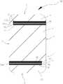
请一并参照图2和图3,壳体1包括第一壳体区域11、第二壳体区域12、第一缝隙带14和第一连接段15,第一缝隙带14设有至少一条第一缝隙142。第一缝隙带14和第一连接段15位于第一壳体区域11和第二壳体区域12之间,第一壳体区域11和第二壳体区域12位于第一缝隙带14的两侧,第一连接段14设置在壳体1的第一缝隙带14的延伸路径的位置处。Referring to FIG. 2 and FIG. 3 together, the
可以理解的,第一缝隙带14设有多条并排间隔第一缝隙142。具体的,壳体1为整片的金属板材的导电材料制成,壳体1包括相对设置的第一长边L1、第二长边L2以及相对设置的一对短边S,一对短边S相对设置且连接在第一长边L1和第二长边L2之间。壳体1除了第一缝隙带14外的导电材料的区域定义金属区域。其中,第一连接段115、第一壳体区域11和第二金属12构成金属区域。第一缝隙带14可以是由壳体1的边缘切入,并未完全切断壳体1,从而使得壳体1的结构完整,进而壳体1能够承受较大的外力作用。具体的,在壳体1上通过激光切割切割多条细小的第一金属条141,其中,相邻两条第一金属条141之间形成一条第一缝隙142,即多条并排间隔设置的第一金属条141形成第一缝隙带14。通过第一缝隙带14将壳体1分割成第一壳体区域11和第二壳体区域12。当然,在其它实施例中,第一缝隙带14还可以是磨床切割而成。It can be understood that the
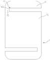
可以理解的,第一缝隙142为长矩形孔缝。可以理解的,第一缝隙带14中的第一缝隙142中可以填充非信号屏蔽材料,如塑胶,在进一步提高壳体1的外观整体性的同时又使得壳体1具有较佳的防水性能。而且非信号屏蔽材料还可为透光的。在天线装置100应用于终端时,终端内部对应第一缝隙带14设置呼吸灯(未图示),从而使得第一缝隙142内的透光非信号屏蔽材料可以透过呼吸灯的光线,从而用户可以从天线装置100的外部观察呼吸灯光线,进而了解终端的运行情况,提高终端的外观效果,并且提高用户体验。较优地,透光非信号屏蔽材料采用导光材料,从而使得第一缝隙带14呈现光带状,进而提高天线装置100的外观效果。当然,在其它实施例中,如图4和图5所示,壳体1上的第一缝隙带14可以只设置一条第一缝隙142。第一缝隙142和第一连接段15将壳体1分隔成第一壳体区域11和第二壳体区域12。It can be understood that the
其中,第一连接段15为导电材料(可以为金属材质),第一连接段15位于壳体1的第一缝隙带14的延伸路径的位置处,即第一连接段15和第一缝隙带14在壳体1的同一排上,可以理解的,第一缝隙带14的延伸路径可以为直线状,即第一缝隙带14沿着短边S的方向的两侧,还可以为第一缝隙带14的中间位置,当第一缝隙带14的延伸路径为直线状,则第一缝隙带14和第一连接段15位于第一壳体区域11和第二壳体区域12之间,该延伸路径使得在壳体1上容易加工出该第一缝隙带14和第一连接段15。可以理解的,第一缝隙带14的延伸路径还可以为波浪状、曲线状,该形状的延伸路径能够改变壳体1的带宽。第一连接段15不但电连接在第一壳体区域11和第二壳体区域12之间,还作为馈电点与匹配电路3电连接,使得金属区域能够接收馈电信号,从而使得金属区域可以辐射电磁波即作为天线装100的辐射体,进而形成天线射频,即第一连接段15、第一壳体区域11和第二壳体区域12作为天线装置100的辐射体,其间,由于第一壳体区域11和第二壳体区域12的面积较大,从而使得天线装置100和具有该天线装置100的移动终端的辐射效率较高。可以理解的,第一连接段15也可以作为天线装置100的回地点,即实现天线装置100辐射体的接地功能。可以理解的,第一连接段15通过金属弹片与主板4上的匹配电路3电连接。当然,在其它实施例中,第一缝隙142还可以为波浪形、闪电状、长椭圆形等。The first connecting
可以理解的,多个第一金属条141等距排列,第一缝隙142的缝宽小于第一金属条141的宽度。具体的,第一金属条141的缝宽与第一缝隙142的宽度之比为1.5~2.0,从而使得相邻第一缝隙142占比较小,用户肉眼无法分辨第一缝隙142,进而整体提高天线装置100的外观效果。优选的,第一缝隙142的缝宽为0.01mm~0.5mm。更为具体的,第一缝隙142的缝宽为0.05mm~0.3mm,第一金属条141的数目大于5个~10个。利用相邻两个第一金属条141之间的缝宽保证最小在0.05mm,使得第一缝隙142无法被用户直接分辨出,并且保证天线装置100最低的射频效率,相反地,控制第一缝隙142的缝宽保证最大在0.3mm,使得天线装置100的射频效率提高。同样,第一金属条141的数目最小控制在5个,以保证天线装置100的外观要求,在第一金属条141的数目最大控制在10个,以提高天线装置100的射频效率。第一缝隙带14的宽度为1.5mm~5.0mm,从而使得第一缝隙带14占整个壳体10的比例较小,从而提高天线装置100的外观效果。本实施例中,第一缝隙142的缝宽为0.06mm,使得第一缝隙142肉眼不可视,进一步提高壳体1的外观整体性。在其它实施例中,第一缝隙142的缝宽可以为0.01mm,第一缝隙142的缝宽可以为0.5mm,第一缝隙142的缝宽可以为0.05mm,第一缝隙142的缝宽可以为0.3mm。优选的,第一缝隙142的数量为2~5条,本实施例中,第一缝隙142的数量为3条,利于天线装置100的辐射。It can be understood that the plurality of
以下以第一缝隙带14的延伸路径为直线状进行举例,为了便于描述,壳体1上除了第一缝隙带14的具有导电材料的区域皆定义为金属区域,该金属区域作为天线装置100的辐射部。The following is an example in which the extending path of the
可以理解的,第一缝隙带14与第一连接段15相靠近的一端与第一连接段15连接。It can be understood that the end of the
一种实施例中,请参照图2,第一缝隙带14包括相对设置的第一开放端14a和第一闭合端14b,第一开放端14a位于第一长边L1上,第一缝隙带14的第一闭合端14b从第一长边L1朝向第二长边L2延伸,壳体1的第一闭合端14b与第二长边L2之间的部分形成第一连接段15。通过将第一缝隙带14设置为上述结构,进一步提高壳体1的金属占比,从而提高壳体1和移动终端的外观整体性。其中,第一金属条141在第一闭合端14b的部分与第一连接段15直接连接,即第一闭合端14b与第一连接段15为非隔离状态。In one embodiment, referring to FIG. 2, the
进一步的,壳体1还包括第三壳体区域13、第二缝隙带16和第二连接段17,第二缝隙带16设有多条并排间隔设置的第二金属条161,第二壳体区域12和第三壳体区域13位于第二缝隙带16的两侧,第二连接段17设置于壳体1之第二缝隙带16的延伸路径的位置处,第二连接段17电连接在第二壳体区域12和第三壳体区域13之间,第二连接段17与匹配电路3电连接。Further, the
具体的,第二缝隙带16的结构可以与第一缝隙带14中的结构相同,在此不再赘述。第二缝隙带16的延伸路径可以第一缝隙带14的延伸路径相同。在通过增加第二缝隙带16和第二连接段17,使得壳体1被分隔成第一壳体区域11、第二壳体区域12和第三壳体区域13,即壳体1形成三个辐射部,进一步提高天线装置100和移动终端的辐射效率。Specifically, the structure of the
可以理解的,第二缝隙带16包括相对设置的第二开放端16a和第二闭合端16b,第二开放端16a位于第二长边L2上,第二缝隙带16的第二闭合端16b从第二长边L2朝向第一长边L1延伸,壳体1之第二闭合端16b与第一长边L1之间的部分形成第二连接段17。其中,第二金属条161在第二闭合端16b的部分与第二连接段17直接连接,即第二闭合端16b与第二连接段17为非隔离状态。It can be understood that the
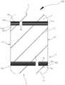
另一种实施例中,请参照图3,壳体1包括相对设置的第一长边L1、第二长边L2以及一对短边S,一对短边S相对设置且连接在第一长边L1和第二长边L2之间,第一缝隙带14从第一长边L1朝向第二长边L2延伸,第一连接段15横跨第一缝隙带14。具体的,第一缝隙带14具有两个第一开放端14a,两个第一开放端14a分别位于第一长边L1和第二长边L2上,第一连接段15横跨第一缝隙带14。也就是说,第一壳体区域11和第二壳体区域12被第一缝隙带14完全分隔,第一连接段15为独立于壳体1的导电片,制造过程中,先形成第一缝隙带14,再制作第一连接段15。第一连接段15可以位于第一缝隙带14的任意位置处。其中,第一金属条141在靠近第一连接段15的部分与第一连接段15直接连接,第一金属条141与第一连接段15为非隔离状态。In another embodiment, referring to FIG. 3, the
进一步的,壳体1还包括第三壳体区域13、第二缝隙带16和第二连接段17,第二缝隙带16设有多条并排间隔设置的第二金属条161,第二壳体区域12和第三壳体区域13位于第二缝隙带16的两侧,第二连接段17设置于壳体1之第二缝隙带16的延伸路径的位置处,第二连接段17电连接在第二壳体区域12和第三壳体区域13之间,第二连接段17与匹配电路3电连接。Further, the
具体的,第二缝隙带16的结构可以与第一缝隙带14中的结构相同,在此不再赘述。第二缝隙带16的延伸路径可以第一缝隙带14的延伸路径相同。通过增加第二缝隙带16和第二连接段17,使得壳体1被分隔成第一壳体区域11、第二壳体区域12和第三壳体区域13,即壳体1形成三个辐射部,进一步提高天线装置100和移动终端的辐射效率。可以理解的,第二缝隙带16从第一长边L1延伸至第二长边L2,第二连接段17横跨第二缝隙带16。其中,第二金属条161在靠近第二连接段17的部分与第二连接段17直接连接,即第二金属条161与第二连接段17为非隔离状态。Specifically, the structure of the
一种实施例中,第一缝隙带14与第二缝隙带16彼此平行。In one embodiment, the
在本发明实施例中的天线装置100和移动终端的辐射体设置在移动终端的壳体1上,且通过缝隙带(第一缝隙带14和/或第二缝隙带16)将壳体1分隔成至少两个壳体区域(第一壳体区域11、第二壳体区域12和第三壳体区域13)形成天线装置100的辐射部,至少两个壳体区域之间通过连接段(第一连接段15和第二连接段17)电连接,并且通过连接段与天线装置100的匹配电路3电连接,进行馈电。本发明提供的移动终端和天线装置100的辐射体的设计利用了移动终端壳体1的结构,辐射面积大,且不需要再额外设计天线辐射体,不但提高了天线装置100的辐射效率,而且使得移动终端整体结构简化,有利于降低移动终端的成本;并且缝隙带为由多条并排间隔设置的金属条(第一金属条141或第二金属条161)组成,使得缝隙带肉眼不可视,提高了壳体1的外观整体性。The
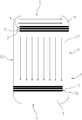
请参阅图7,图7所示为天线装置100的壳体1的电流分布示意图。图6中,第一连接段15连接匹配电路3成为馈电点,这样,第一壳体区域11上的电流方向从第二长边L2流向第一长边L1,第二壳体区域12上的电流方向为从第一缝隙带14朝向垂直于第一缝隙带14的方向。Please refer to FIG. 7. FIG. 7 is a schematic diagram showing current distribution of the
请参照图8和图9,为本发明实施方式二提供的一种天线装置200,该天线装置200与实施例一提供的天线装置100基本相同,其不同之处在于,第一缝隙带14与第一连接段15相靠近的一端与第一连接段15隔离,并且对应该第一缝隙带14的结构,天线装置200还进一步设置了开关6,开关6连接于第一缝隙带14中的一条第一金属条141,用于导通或断开辐射部与第一金属条141之间的电连接。通过第一金属条141与壳体1除了第一缝隙带14外的金属区域即辐射部(第一连接段、第一壳体区域和第二壳体区域)相隔离,利用开关6控制第一金属条141与辐射部的导通状态,从而使得辐射部的谐振频率产生变化,即天线装置200的频段增加,从而增加带宽,提高用户体验。8 and FIG. 9 is an
可以理解的,开关6可以是单刀多掷开关,也可以是单刀单掷开关。具体的,开关6包括动触头61和静触头62,动触头61电连接辐射部,静触头62电连接第一金属条141,动触头61与静触头62导通或断开,从而导通或断开辐射部与第一金属条141之间的电连接。动触头61可以与终端的中央处理器连接,以根据终端的控制信号与静触头62相导通。静触头62的数量可以是一个也可以是多个,一个或多个静触头62可以对应连接至一个或多个第一金属条141。It can be understood that the
如图8所示,开关6的静触头62的数量为一个,一个静触头62与其中一个第一金属条141电连接。当动触头61与静触头62相导通时,与该静触头62电连接的第一金属条141经动触头61与辐射部相导通,从而改变辐射部的产生第一谐振频率的电磁波。当静触头62与第一金属条141断开时,第一金属条141和金属区域相断开,金属区域辐射第二谐振频率的电磁波,第二谐振频率不同于第一谐振频率。进而,天线装置可以产生不同谐振频率的电磁信号,进而带宽增加,提高用户体验。As shown in FIG. 8, the number of the
如图9所示,开关6的静触头62的数量为两个,两个静触头62与其中两个第一金属条141电连接,动触头61与其中一个静触头62导通或断开。具体的,两个静触头62分别是第一静触头621和第二静触头622。多个第一金属条141中包括一条第一金属条1411和另一条第一金属条1412。两条第一金属条141相邻设置。一条第一金属条1411相较于另一条第一金属条1412靠近第二壳体区域12,即一条第一金属条1411至第二壳体区域12的距离小于另一条第一金属条1412至金属区域12的距离。第一静触头621电连接第一金属条141,第二静触头622电连接另一条第一金属条1412。当动触头61与一条第一金属条1411导通时,辐射部辐射第一谐振频率的电磁波。当动触头61与另一条第一金属条1412导通时,由于另一条第一金属条1412与第二辐射部12之间形成的缝宽尺寸大于第一金属条141与辐射部之间形成的缝宽尺寸,进而使得辐射部所辐射的谐振频率改变,即辐射部辐射第三谐振频率的电磁波且第三谐振频率不同于第一谐振频率和第二谐振频率。进一步使得天线装置200可以辐射更多不同谐振频率的电磁波,形成更多的频段,方便用户在不同的频段间进行选择,进一步地增加天线带宽。同理,在其他实施方式中,还可以设置多个静触头62对应电连接至多个第一金属条141,从而根据每一第一金属条141与辐射部之间形成不同尺寸的缝宽,导致辐射部所辐射的谐振频率不同,从而形成更多的频段,为用户提供更多的频段选择。As shown in FIG. 9, the number of the
一种实施例中,请参照图8,第一缝隙带14包括相对设置的第一开放端14a和第一闭合端14b,第一开放端14a位于第一长边L1上,第一缝隙带14的第一闭合端14b从第一长边L1朝向第二长边L2延伸,壳体1的第一闭合端14b与第二长边L2之间的部分形成第一连接段15。通过将第一缝隙带14设置为上述结构,进一步提高壳体1的金属占比,从而提高壳体1和移动终端的外观整体性。其中,第一金属条141在第一闭合端14b的部分与第一连接段15相隔离,即第一闭合端14b与第一连接段15为隔离状态。In one embodiment, referring to FIG. 8, the
进一步的,壳体1还包括第三壳体区域13、第二缝隙带16和第二连接段17,第二缝隙带16设有多条并排间隔设置的第二金属条161,第二壳体区域12和第三壳体区域13位于第二缝隙带16的两侧,第二连接段17设置于壳体1之第二缝隙带16的延伸路径的位置处,第二连接段17电连接在第二壳体区域12和第三壳体区域13之间,第二连接段17与匹配电路3电连接。Further, the
具体的,第二缝隙带16的结构可以与第一缝隙带14中的结构相同,在此不再赘述。第二缝隙带16的延伸路径可以第一缝隙带14的延伸路径相同。在通过增加第二缝隙带16和第二连接段17,使得壳体1被分隔成第一壳体区域11、第二壳体区域12和第三壳体区域13,即壳体1形成三个辐射部,进一步提高天线装置100和移动终端的辐射效率。Specifically, the structure of the
可以理解的,第二缝隙带16包括相对设置的第二开放端16a和第二闭合端16b,第二开放端16a位于第二长边L2上,第二缝隙带16的第二闭合端16b从第二长边L2朝向第一长边L1延伸,壳体1之第二闭合端16b与第一长边L1之间的部分形成第二连接段17。其中,第二金属条在第二闭合端16b的部分与第二连接段17直接连接,即第二闭合端16b与第二连接段17为非隔离状态。It can be understood that the
另一种实施例中,请参照图9,壳体1包括相对设置的第一长边L1、第二长边L2以及一对短边S,一对短边S相对设置且连接在第一长边L1和第二长边L2之间,第一缝隙带14从第一长边L1朝向第二长边L2延伸,第一连接段15横跨第一缝隙带14。具体的,第一缝隙带14具有两个第一开放端14a,两个第一开放端14a分别位于第一长边L1和第二长边L2上,第一连接段15横跨第一缝隙带14。也就是说,第一壳体区域11和第二壳体区域12被第一缝隙带14完全分隔,第一连接段15为独立于壳体1的导电片,制造过程中,先形成第一缝隙带14,再制作第一连接段15。第一连接段15可以位于第一缝隙带14的任意位置处。其中,第一金属条141在靠近第一连接段15的部分与第一连接段15相隔离,第一金属条141与第一连接段15为隔离状态。In another embodiment, referring to FIG. 9, the
进一步的,壳体1还包括第三壳体区域13、第二缝隙带16和第二连接段17,第二缝隙带16设有多条并排间隔设置的第二金属条161,第二壳体区域12和第三壳体区域13位于第二缝隙带16的两侧,第二连接段17设置于壳体1之第二缝隙带16的延伸路径的位置处,第二连接段17电连接在第二壳体区域12和第三壳体区域13之间,第二连接段17与匹配电路3电连接。Further, the
具体的,第二缝隙带16的结构可以与第一缝隙带14中的结构相同,在此不再赘述。第二缝隙带16的延伸路径可以第一缝隙带14的延伸路径相同。通过增加第二缝隙带16和第二连接段17,使得壳体1被分隔成第一壳体区域11、第二壳体区域12和第三壳体区域13,即壳体1形成三个辐射部,进一步提高天线装置100和移动终端的辐射效率。可以理解的,第二缝隙带16从第一长边L1延伸至第二长边L2,第二连接段17横跨第二缝隙带16。其中,第二金属条161在靠近第二连接段17的部分与第二连接段17相隔离,即第二金属条161与第二连接段17为隔离状态。Specifically, the structure of the
一种实施例中,第一缝隙带14与第二缝隙带16彼此平行。In one embodiment, the
在本发明实施例中的天线装置200和移动终端的辐射体设置在移动终端的壳体1上,且通过缝隙带(第一缝隙带14和/或第二缝隙带16)将壳体1分隔成至少两个壳体区域(第一壳体区域11、第二壳体区域12和第三壳体区域13)形成天线装置200的辐射部,至少两个壳体区域之间通过连接段(第一连接段15和第二连接段17)电连接,并且通过连接段与天线装置200的匹配电路3电连接,进行馈电。The
本发明提供的移动终端和天线装置200的辐射体的设计利用了移动终端壳体1的结构,辐射面积大,且不需要再额外设计天线辐射体,不但提高了天线装置200的辐射效率,而且使得移动终端整体结构简化,有利于降低移动终端的成本;并且缝隙带为由多条并排间隔设置的金属条(第一金属条141或第二金属条161)组成,使得缝隙带肉眼不可视,提高了壳体1的外观整体性。The design of the radiator of the mobile terminal and the
在本发明实施例中的天线装置200还通过第一金属条161与壳体1除了第一缝隙带14外的金属区域即辐射部(第一连接段、第一壳体区域和第二壳体区域)相隔离,利用开关6控制第一金属条141与辐射部的导通状态,从而使得辐射部的谐振频率产生变化,即天线装置200的频段增加,从而增加带宽,提高用户体验。The
以上对本发明实施例进行了详细介绍,本文中应用了具体个例对本发明的原理及实施方式进行了阐述,以上实施例的说明只是用于帮助理解本发明的方法及其核心思想;同时,对于本领域的一般技术人员,依据本发明的思想,在具体实施方式及应用范围上均会有改变之处,综上,本说明书内容不应理解为对本发明的限制。The embodiments of the present invention have been described in detail above, and the principles and implementations of the present invention are described in detail herein. The description of the above embodiments is only for helping to understand the method of the present invention and its core ideas; The present invention is not limited by the scope of the present invention, and the details of the present invention are not limited by the scope of the present invention.
Claims (30)
Translated fromChinesePriority Applications (3)
| Application Number | Priority Date | Filing Date | Title |
|---|---|---|---|
| EP16895065.7AEP3273536B1 (en) | 2016-03-21 | 2016-06-21 | Housing, antenna apparatus and mobile terminal |
| ES16895065TES2746203T3 (en) | 2016-03-21 | 2016-06-21 | Housing, antenna device and mobile terminal |
| US15/798,823US10886597B2 (en) | 2016-03-21 | 2017-10-31 | Housing, antenna device and mobile terminal |
Applications Claiming Priority (6)
| Application Number | Priority Date | Filing Date | Title |
|---|---|---|---|
| CN201610163702.0ACN105655701B (en) | 2016-03-21 | 2016-03-21 | Antenna device and mobile terminal |
| CN201610163702.0 | 2016-03-21 | ||
| CN201610287147.2ACN105762493B (en) | 2016-04-29 | 2016-04-29 | Metal shell, antenna device and mobile terminal |
| CN201610287114.8 | 2016-04-29 | ||
| CN201610287114.8ACN105789833B (en) | 2016-04-29 | 2016-04-29 | Antenna device and mobile terminal |
| CN201610287147.2 | 2016-04-29 |
Related Child Applications (1)
| Application Number | Title | Priority Date | Filing Date |
|---|---|---|---|
| US15/798,823ContinuationUS10886597B2 (en) | 2016-03-21 | 2017-10-31 | Housing, antenna device and mobile terminal |
Publications (1)
| Publication Number | Publication Date |
|---|---|
| WO2017161713A1true WO2017161713A1 (en) | 2017-09-28 |
Family
ID=59899269
Family Applications (1)
| Application Number | Title | Priority Date | Filing Date |
|---|---|---|---|
| PCT/CN2016/086566CeasedWO2017161713A1 (en) | 2016-03-21 | 2016-06-21 | Housing, antenna apparatus and mobile terminal |
Country Status (4)
| Country | Link |
|---|---|
| US (1) | US10886597B2 (en) |
| EP (1) | EP3273536B1 (en) |
| ES (1) | ES2746203T3 (en) |
| WO (1) | WO2017161713A1 (en) |
Families Citing this family (4)
| Publication number | Priority date | Publication date | Assignee | Title |
|---|---|---|---|---|
| KR102393808B1 (en)* | 2017-06-20 | 2022-05-04 | 삼성전자주식회사 | An electronic device comprising antenna |
| KR102486184B1 (en)* | 2018-07-06 | 2023-01-10 | 삼성전자주식회사 | Antenna structure and electronic device including the same |
| CN109244664A (en)* | 2018-09-30 | 2019-01-18 | 联想(北京)有限公司 | A kind of electronic equipment |
| KR102682163B1 (en)* | 2019-07-05 | 2024-07-08 | 삼성전자주식회사 | Antenna structure and electronic device including the same |
Citations (5)
| Publication number | Priority date | Publication date | Assignee | Title |
|---|---|---|---|---|
| CN102142855A (en)* | 2010-05-27 | 2011-08-03 | 苹果公司 | Shell structure for optimizing position of transmitted radio frequency signal |
| US8373610B2 (en)* | 2007-12-18 | 2013-02-12 | Apple Inc. | Microslot antennas for electronic devices |
| CN203775569U (en)* | 2014-03-28 | 2014-08-13 | 华为终端有限公司 | Electronic device and metal housing thereof |
| CN104584324A (en)* | 2014-03-28 | 2015-04-29 | 华为终端有限公司 | Integrated structure of electronic device metal case and antenna |
| CN105655701A (en)* | 2016-03-21 | 2016-06-08 | 广东欧珀移动通信有限公司 | Antenna device and mobile terminal |
Family Cites Families (19)
| Publication number | Priority date | Publication date | Assignee | Title |
|---|---|---|---|---|
| TW541759B (en) | 2002-07-24 | 2003-07-11 | Ind Tech Res Inst | Foldable dual-band monopole antenna |
| WO2010073723A1 (en)* | 2008-12-25 | 2010-07-01 | 京セラ株式会社 | Portable terminal |
| WO2010116589A1 (en)* | 2009-03-30 | 2010-10-14 | 日本電気株式会社 | Slot antenna, electronic apparatus, and method for manufacturing slot antenna |
| US8711044B2 (en)* | 2009-11-12 | 2014-04-29 | Nokia Corporation | Antenna arrangement and antenna housing |
| US9300033B2 (en)* | 2011-10-21 | 2016-03-29 | Futurewei Technologies, Inc. | Wireless communication device with an antenna adjacent to an edge of the device |
| CN103891043B (en)* | 2011-10-31 | 2015-11-25 | 索尼爱立信移动通讯有限公司 | Adopt multiple-input and multiple-output (MIMO) antenna of multiband trapper |
| US9350069B2 (en)* | 2012-01-04 | 2016-05-24 | Apple Inc. | Antenna with switchable inductor low-band tuning |
| US9203139B2 (en)* | 2012-05-04 | 2015-12-01 | Apple Inc. | Antenna structures having slot-based parasitic elements |
| US9122966B2 (en)* | 2012-09-07 | 2015-09-01 | Lawrence F. Glaser | Communication device |
| US9716307B2 (en)* | 2012-11-08 | 2017-07-25 | Htc Corporation | Mobile device and antenna structure |
| CN103280623B (en) | 2013-05-27 | 2017-02-22 | 努比亚技术有限公司 | Antenna structure |
| WO2015026199A1 (en)* | 2013-08-23 | 2015-02-26 | Samsung Electronics Co., Ltd. | Electronic device and method of operating the same |
| TWI557984B (en)* | 2014-03-05 | 2016-11-11 | 緯創資通股份有限公司 | Wearable device |
| CN203886669U (en) | 2014-05-21 | 2014-10-22 | 国电环境保护研究院 | Flexible anode tensioning fixing device of wet electric dust remover |
| CN204216211U (en)* | 2014-11-12 | 2015-03-18 | 瑞声声学科技(苏州)有限公司 | Communication terminal |
| CN205081217U (en) | 2015-10-23 | 2016-03-09 | 广东欧珀移动通信有限公司 | Slot antenna and cell -phone of cell -phone |
| CN205092313U (en) | 2015-11-05 | 2016-03-16 | 广东欧珀移动通信有限公司 | Metal casing antenna device and mobile terminal |
| CN105337036B (en) | 2015-11-12 | 2018-09-07 | 深圳市万普拉斯科技有限公司 | Mobile terminal and its antenna structure |
| CN205657165U (en) | 2016-04-29 | 2016-10-19 | 广东欧珀移动通信有限公司 | Antenna device and mobile terminal |
- 2016
- 2016-06-21WOPCT/CN2016/086566patent/WO2017161713A1/ennot_activeCeased
- 2016-06-21EPEP16895065.7Apatent/EP3273536B1/enactiveActive
- 2016-06-21ESES16895065Tpatent/ES2746203T3/enactiveActive
- 2017
- 2017-10-31USUS15/798,823patent/US10886597B2/ennot_activeExpired - Fee Related
Patent Citations (5)
| Publication number | Priority date | Publication date | Assignee | Title |
|---|---|---|---|---|
| US8373610B2 (en)* | 2007-12-18 | 2013-02-12 | Apple Inc. | Microslot antennas for electronic devices |
| CN102142855A (en)* | 2010-05-27 | 2011-08-03 | 苹果公司 | Shell structure for optimizing position of transmitted radio frequency signal |
| CN203775569U (en)* | 2014-03-28 | 2014-08-13 | 华为终端有限公司 | Electronic device and metal housing thereof |
| CN104584324A (en)* | 2014-03-28 | 2015-04-29 | 华为终端有限公司 | Integrated structure of electronic device metal case and antenna |
| CN105655701A (en)* | 2016-03-21 | 2016-06-08 | 广东欧珀移动通信有限公司 | Antenna device and mobile terminal |
Also Published As
| Publication number | Publication date |
|---|---|
| EP3273536A4 (en) | 2018-05-23 |
| US20180069293A1 (en) | 2018-03-08 |
| EP3273536A1 (en) | 2018-01-24 |
| ES2746203T3 (en) | 2020-03-05 |
| EP3273536B1 (en) | 2019-08-14 |
| US10886597B2 (en) | 2021-01-05 |
Similar Documents
| Publication | Publication Date | Title |
|---|---|---|
| TWI691119B (en) | Antenna structure and wireless communication device with same | |
| CN108039566B (en) | Metal Terminal Back Covers and Terminals | |
| CN105789833B (en) | Antenna device and mobile terminal | |
| TWI652853B (en) | Antenna device and mobile device | |
| TWI645614B (en) | Antenna structure and wireless communication device having the same | |
| WO2017156900A1 (en) | Metal housing, antenna device, and mobile terminal | |
| CN109286077B (en) | mobile device | |
| TW201824640A (en) | Mobile device and manufacturing method thereof | |
| WO2017161713A1 (en) | Housing, antenna apparatus and mobile terminal | |
| CN205657168U (en) | Metal casing , antenna device and mobile terminal | |
| TWI637556B (en) | Antenna structure and wireless communication device with same | |
| CN107834173A (en) | Metal shell, antenna device and mobile terminal | |
| CN205657165U (en) | Antenna device and mobile terminal | |
| JP2011155531A (en) | Antenna and portable radio terminal | |
| CN111478016A (en) | Mobile device | |
| CN205583140U (en) | Metal terminal back cover and terminal | |
| TWI724754B (en) | Antenna structure and wireless communication device with same | |
| TW201701529A (en) | Wireless communication apparatus and antenna module thereof | |
| CN109309284A (en) | Antenna device and mobile device | |
| CN112311910A (en) | Mobile device | |
| CN110875514A (en) | mobile device | |
| CN205985342U (en) | Casing, antenna device and mobile terminal | |
| TWI758973B (en) | Antenna structure and electronc device with same | |
| TWI724738B (en) | Antenna structure and wireless communication device with same | |
| TWI656752B (en) | Antenna device and mobile terminal |
Legal Events
| Date | Code | Title | Description |
|---|---|---|---|
| REEP | Request for entry into the european phase | Ref document number:2016895065 Country of ref document:EP | |
| NENP | Non-entry into the national phase | Ref country code:DE |