WO2017156958A1 - Wire winding module - Google Patents
Wire winding moduleDownload PDFInfo
- Publication number
- WO2017156958A1 WO2017156958A1PCT/CN2016/092695CN2016092695WWO2017156958A1WO 2017156958 A1WO2017156958 A1WO 2017156958A1CN 2016092695 WCN2016092695 WCN 2016092695WWO 2017156958 A1WO2017156958 A1WO 2017156958A1
- Authority
- WO
- WIPO (PCT)
- Prior art keywords
- wire
- cover
- winding module
- rotating wheel
- runner
- Prior art date
- Legal status (The legal status is an assumption and is not a legal conclusion. Google has not performed a legal analysis and makes no representation as to the accuracy of the status listed.)
- Ceased
Links
Images


Classifications
- B—PERFORMING OPERATIONS; TRANSPORTING
- B65—CONVEYING; PACKING; STORING; HANDLING THIN OR FILAMENTARY MATERIAL
- B65H—HANDLING THIN OR FILAMENTARY MATERIAL, e.g. SHEETS, WEBS, CABLES
- B65H75/00—Storing webs, tapes, or filamentary material, e.g. on reels
- B65H75/02—Cores, formers, supports, or holders for coiled, wound, or folded material, e.g. reels, spindles, bobbins, cop tubes, cans, mandrels or chucks
- B65H75/34—Cores, formers, supports, or holders for coiled, wound, or folded material, e.g. reels, spindles, bobbins, cop tubes, cans, mandrels or chucks specially adapted or mounted for storing and repeatedly paying-out and re-storing lengths of material provided for particular purposes, e.g. anchored hoses, power cables
- B65H75/38—Cores, formers, supports, or holders for coiled, wound, or folded material, e.g. reels, spindles, bobbins, cop tubes, cans, mandrels or chucks specially adapted or mounted for storing and repeatedly paying-out and re-storing lengths of material provided for particular purposes, e.g. anchored hoses, power cables involving the use of a core or former internal to, and supporting, a stored package of material
- B65H75/44—Constructional details
- B65H75/48—Automatic re-storing devices
- B65H75/486—Arrangements or adaptations of the spring motor
- H—ELECTRICITY
- H01—ELECTRIC ELEMENTS
- H01R—ELECTRICALLY-CONDUCTIVE CONNECTIONS; STRUCTURAL ASSOCIATIONS OF A PLURALITY OF MUTUALLY-INSULATED ELECTRICAL CONNECTING ELEMENTS; COUPLING DEVICES; CURRENT COLLECTORS
- H01R13/00—Details of coupling devices of the kinds covered by groups H01R12/70 or H01R24/00 - H01R33/00
- H01R13/72—Means for accommodating flexible lead within the holder
- B—PERFORMING OPERATIONS; TRANSPORTING
- B65—CONVEYING; PACKING; STORING; HANDLING THIN OR FILAMENTARY MATERIAL
- B65H—HANDLING THIN OR FILAMENTARY MATERIAL, e.g. SHEETS, WEBS, CABLES
- B65H75/00—Storing webs, tapes, or filamentary material, e.g. on reels
- B65H75/02—Cores, formers, supports, or holders for coiled, wound, or folded material, e.g. reels, spindles, bobbins, cop tubes, cans, mandrels or chucks
- B65H75/34—Cores, formers, supports, or holders for coiled, wound, or folded material, e.g. reels, spindles, bobbins, cop tubes, cans, mandrels or chucks specially adapted or mounted for storing and repeatedly paying-out and re-storing lengths of material provided for particular purposes, e.g. anchored hoses, power cables
- B65H75/38—Cores, formers, supports, or holders for coiled, wound, or folded material, e.g. reels, spindles, bobbins, cop tubes, cans, mandrels or chucks specially adapted or mounted for storing and repeatedly paying-out and re-storing lengths of material provided for particular purposes, e.g. anchored hoses, power cables involving the use of a core or former internal to, and supporting, a stored package of material
- B65H75/44—Constructional details
- B65H75/4418—Arrangements for stopping winding or unwinding; Arrangements for releasing the stop means
- B65H75/4428—Arrangements for stopping winding or unwinding; Arrangements for releasing the stop means acting on the reel or on a reel blocking mechanism
- B65H75/4431—Manual stop or release button
- H—ELECTRICITY
- H01—ELECTRIC ELEMENTS
- H01R—ELECTRICALLY-CONDUCTIVE CONNECTIONS; STRUCTURAL ASSOCIATIONS OF A PLURALITY OF MUTUALLY-INSULATED ELECTRICAL CONNECTING ELEMENTS; COUPLING DEVICES; CURRENT COLLECTORS
- H01R12/00—Structural associations of a plurality of mutually-insulated electrical connecting elements, specially adapted for printed circuits, e.g. printed circuit boards [PCB], flat or ribbon cables, or like generally planar structures, e.g. terminal strips, terminal blocks; Coupling devices specially adapted for printed circuits, flat or ribbon cables, or like generally planar structures; Terminals specially adapted for contact with, or insertion into, printed circuits, flat or ribbon cables, or like generally planar structures
- H01R12/70—Coupling devices
- H01R12/77—Coupling devices for flexible printed circuits, flat or ribbon cables or like structures
- H—ELECTRICITY
- H01—ELECTRIC ELEMENTS
- H01R—ELECTRICALLY-CONDUCTIVE CONNECTIONS; STRUCTURAL ASSOCIATIONS OF A PLURALITY OF MUTUALLY-INSULATED ELECTRICAL CONNECTING ELEMENTS; COUPLING DEVICES; CURRENT COLLECTORS
- H01R35/00—Flexible or turnable line connectors, i.e. the rotation angle being limited
- H—ELECTRICITY
- H02—GENERATION; CONVERSION OR DISTRIBUTION OF ELECTRIC POWER
- H02G—INSTALLATION OF ELECTRIC CABLES OR LINES, OR OF COMBINED OPTICAL AND ELECTRIC CABLES OR LINES
- H02G11/00—Arrangements of electric cables or lines between relatively-movable parts
- H02G11/02—Arrangements of electric cables or lines between relatively-movable parts using take-up reel or drum
- B—PERFORMING OPERATIONS; TRANSPORTING
- B65—CONVEYING; PACKING; STORING; HANDLING THIN OR FILAMENTARY MATERIAL
- B65H—HANDLING THIN OR FILAMENTARY MATERIAL, e.g. SHEETS, WEBS, CABLES
- B65H2701/00—Handled material; Storage means
- B65H2701/30—Handled filamentary material
- B65H2701/39—Other types of filamentary materials or special applications
- B65H2701/3919—USB, earphones, audio or video cables, e.g. for connecting small electronic devices such as MP3 players or mobile telephones
Definitions
- the inventionrelates to a winding module for accommodating wires or signal wires of an electronic device.
- Auxiliary devices with wiressuch as headphones, mice, keyboards, etc.
- the winding moduleis usually provided with a rotating wheel, a coil spring and a stopping structure.
- the wireis wound around the rotating wheel, and the wire can be automatically retracted under the elastic restoring force of the coil spring.
- the stopping structurecan prevent the rotation.
- the wheelrotates to prevent the retracting action of the wheel, so that the wire of the appropriate length can be reserved without retracting.
- the stopping structureis provided with a stop button and an elastic supporting device.
- the elastic supporting devicecan provide the elastic force by the button, and the stopping structure automatically brakes the rotating wheel under the action of the elastic force, and the pressing button can release the rotating wheel. Start the wire retraction action.
- the winding module stop structure on the marketis elastically supported by a compression spring or a torsion spring structure, and this structure takes up a large space, which limits the miniaturization of the product.
- a winding wire module stopping structureis disclosed, and the spring 415 is an elastic supporting device of the locking device 400, from FIG. 4 and the drawing. It can be seen that the spring 415 is a compression spring and has a certain height. For this reason, the second chamber accommodating spring 415 is specifically disposed on the mounting portion 230, and the occupied space is large.
- a winding module stop structureis disclosed, and the elastic member 420 is an elastic supporting device of the locking assembly 400, as can be seen from FIG. 4 and FIG.
- the elastic member 420is a compression spring having a certain height.
- the fixing member 440is specially provided with a fixing groove 444 for accommodating the elastic member 420, which occupies a large space.
- a winding module stop structureis disclosed, and the hook spring 13 is a hook
- the hook spring 13is a torsion spring having a certain height.
- the base 8is provided with a fixing groove mounting hook spring 13 on the side of the base 8, and the occupied space is also large.
- the present inventionprovides a winding module that uses a spring wire in conjunction with a stop mechanism of a stop button to make the size of the winding module more compact.
- a winding moduleis provided with a rotating wheel, and a wire is wound around the rotating wheel, and a stop button is arranged in cooperation with the rotating wheel, and a spring wire is matched with the stopping button as an elastic supporting device in the spring line
- the spring buttonautomatically brakes the wheel under the action of the elastic force to prevent the wheel from retracting the wire; the spring wire is curved or curved by the pre-pressing deformation of the button.
- the winding moduleis provided with a fixing cover
- the rotating wheelis mounted under the fixing cover
- the stopping buttonis mounted on one side of the fixing cover
- the cover body of the fixing coveris provided with a receiving groove.
- the spring wireis mounted in the receiving groove to push the stop button to drive the stop button to brake the wheel; the receiving groove is curved, and the two ends of the spring wire are bent to form a fitting portion.
- the stop buttonis a lever structure
- the middle portionis provided with a mounting hole
- the matching pinis mounted on one side of the fixed cover
- the stop buttonis rotated around the pin
- the end of the stop button and the rotating wheelis provided with a spine
- a plastic sleeveis mounted on the claw and the pawl.
- a ratchetis mounted on the upper end of the rotating wheel to cooperate with the stopping button; a shaft hole is disposed in a middle portion of the rotating wheel, and a rotating shaft is fixed on the fixed cover, and the rotating wheel rotates around the rotating shaft.
- the lower end of the rotating shaftis provided with a snap ring, and the snap ring limits the runner to the rotating shaft.
- the upper end of the rotating wheelis provided with a mounting slot
- the mounting slotis provided with a circuit connecting elastic piece
- the lower end surface of the fixing coveris provided with an FPC connecting terminal
- one end of the circuit connecting elastic pieceis connected with the wire, and one end is connected with the FPC terminal.
- the circuit connection springis driven by the wheel to rotate relative to the FPC connection terminal.
- the FPC connection terminalis a circular ring, and is connected to an external flexible circuit board.
- the circuit connection elastic pieceis two pieces, and the symmetric arrangement is respectively in contact with the FPC connection terminal, and the rotation wheel is connected through the circuit.
- the projecting pieceforms a preload on the FPC connection terminal.
- one end of the circuit connecting elastic piece contacting the FPC connecting terminalis a fork structure, and has a circular arc segment, and is in contact with the FPC connecting terminal through the circular arc segment.
- the lower end of the rotating wheelis provided with an energy storage cavity, and a coil spring is mounted in the energy storage cavity, one end of the coil spring is fixed to the rotating shaft, and one end is fixed to the side wall of the energy storage cavity, and the wire is pulled And the rotating wheel rotates and tightens the coil spring to store energy, and provides preparatory power for retracting the wire.
- the energy storage chamberis mounted with a runner cover, a seal ring is disposed in the runner cover, and a seal ring is also disposed in the shaft hole, and a damping grease is disposed in the energy storage chamber, and the seal ring is prevented Damping grease leaks.
- the side wall of the wheel coveris provided with a card hole
- the side wall of the energy storage cavityis provided with a claw
- the energy storage cavityis coupled with the wheel cover;
- the cover of the wheel cover A crackis disposed on both sides of the card hole on the side wall, allowing the side wall of the position to expand outwardly to deform and fit the claw.
- the mechanismadopts a spring wire and a stop button structure, which occupies a small space and makes the size of the winding module more compact.
- the energy storage chamber of the installation coil springis provided with damping grease, which can adjust the release speed of the coil spring, and the wire is slowly retracted to prevent damage to the wire.
- connection between the wire and the external circuitis realized by the contact FPC connection terminal and the circuit connection elastic piece, and the elastic contact between the two is always unaffected by the rotation of the wheel, and has no influence on the circuit signal.
- Figure 1is an exploded view of the present invention
- Figure 2is a cross-sectional view of the present invention
- Figure 3is an assembled view of the present invention (without a fixed cover);
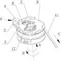
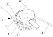
- Figure 4is an assembled view of the present invention (the fixed cover is installed, the spring wire is not installed in place);
- Figure 5is an assembled view of the present invention (spring wire is installed in place);
- Figure 6is a perspective view of a runner used in the present invention.
- Figure 7is a perspective view of the circuit connecting elastic piece used in the present invention.
- sealing ring11. wire; 12. coil spring; 13. rotating sleeve; 14. retaining ring; 15. sealing ring; 16. rotating wheel cover;
- the winding moduleis provided with a runner 9, and the wire 11 or the signal wire is wound around the runner 9, and is arranged to cooperate with the runner 9.
- the movable button 4is matched with the stop button 4 with the spring wire 5 as an elastic supporting device. Under the elastic force of the spring wire 5, the stop button 4 automatically prevents the rotating wheel 9 from rotating, and the spring wire 5 is curved or stopped.
- the push button 4is pre-stressed and deformed in an arc shape.
- the stop button 4automatically prevents the rotation of the wheel 9 to prevent rotation when the wire 11 is retracted, and the rotation of the release wire 11 cannot be prevented, which is a structural requirement of the ratchet 9-1 and the pawl.
- the stop button 4can be a metal button.
- the spring wire 5is a single spring wire. According to the elastic force, a single spring wire can also be folded to form two spring wires arranged side by side, so that the design can improve the elastic force and prolong the use time.
- the arc shape of the spring wire 5may also be referred to as a bow shape, which may be curved when not pre-pressed or curved by pre-compression deformation. After installation, the spring wire 5 is required to form sufficient elastic support for the stop button 4.
- the winding moduleis provided with a fixing cover 6, and the rotating wheel 9 is installed under the fixing cover 6, and the stopping button 4 is mounted on the side of the fixing cover 6, and the cover of the fixing cover 6 is fixed.
- a receiving grooveis provided, and the spring wire 5 is mounted in the receiving groove to push the stop button 4 to drive the stopping button 4 to brake the rotating wheel 9; the receiving groove is curved, and the two ends of the spring wire 5 are bent to form a fitting portion.
- the ends of the spring wire 5may also not be bent, but it is easier to fit with other components after bending.
- the spring wire 5is mounted substantially horizontally in the receiving groove, i.e., the arc-shaped radial direction is parallel to the plane of the fixed cover 6, so that the height can be effectively reduced and the space occupied is small.
- the stop button 4is a lever structure, the middle portion is provided with a mounting hole, the matching pin 2 is mounted on the side of the fixed cover 6, the stop button 4 is rotated around the pin 2, and the end of the stop button 4 and the runner 9 is provided with a pawl.
- a plastic sleeve 3is mounted on the pawl. When the reel 9 releases the wire 11 to rotate, the plastic sleeve 3 acts as a lubrication between the pawl and the runner 9.
- a ratchet 9-1is mounted on the upper end of the runner 9 and cooperates with the stop button 4; a shaft hole is arranged in the middle of the runner 9, a rotating shaft 1 is fixed on the fixed cover 6, the runner 9 rotates around the rotating shaft 1, and a card is arranged at the lower end of the rotating shaft 1
- the ring 14, the snap ring 14limits the runner 9 to the spindle 1.
- the upper end of the runner 9is provided with a mounting slot 9-2
- the mounting slot 9-2is provided with a circuit connecting elastic piece 8
- the lower end surface of the fixing cover 6is provided with an FPC connecting terminal 7,
- One end of the circuit connecting elastic piece 8is connected to the wire 11, one end is connected to the FPC connection terminal 7, and the circuit connecting elastic piece 8 is driven by the rotating wheel 9 to rotate relative to the FPC connecting terminal 7.
- the FPC connection terminal 7is a circular ring, and is connected to an external flexible circuit board (ie, FPC).
- the circuit connection elastic piece 8is two pieces, and the symmetric arrangement is respectively in contact with the FPC connection terminal 7, and the rotation wheel 9 is connected to the FPC connection terminal 7 through the circuit connection elastic piece 8. The pre-compression is formed, so that the reliability of the circuit connection can be fully ensured.
- Both the FPC connection terminal 7 and the circuit connection spring 8are made of a material having good electrical conductivity, such as a copper alloy.
- one end of the circuit connection elastic piece 8 in contact with the FPC connection terminal 7is a fork structure (the upper connection terminal 8-1 in FIG. 7), and has a circular arc section, and is connected to the FPC through the arc segment. 7 contact, this can reduce the friction when sliding.
- a fixing hole 8-3is disposed in the middle of the circuit connecting elastic piece 8.
- the mounting groove 9-2is also provided with a pin to cooperate with it.
- the lower end of the runner 9is provided with an energy storage chamber 9-4, and the coil spring 9 is mounted with a coil spring 12, and one end of the coil spring 12 It is fixed to the rotating shaft 1, and one end is fixed to the side wall of the energy storage chamber.
- the rotating wheel 9rotates and tightens the coil spring 12 for energy storage, and provides preparatory power for retracting the wire 11.
- the energy storage chamber 9-4is mounted with a runner cover 16.
- the side wall of the runner cover 16is provided with a card hole, and the side wall of the energy storage chamber 9-4 is provided with a claw 9-5, and the energy storage chamber 9-4 is coupled with the wheel cover 16; the wheel cover 16 A crack is provided on both sides of the card hole on the side wall, allowing the side wall of the position to expand outwardly to deform the adapting claw 9-5.
- the lower end of the spring wire 5contacts the upper end of the stop button 4 and maintains a certain amount of preload of the spring wire 5, so that the stop button 4 is always urged by the spring wire 5 in the opposite direction of the force F.
- the plastic sleeve 3maintains a tendency to snap into the end ratchet of the runner 9.
- the angle between the ratchet of the end face of the runner 9 and the tangent of the outer contouris the left acute angle and the right right angle design.
- the runner 9can rotate clockwise along the B direction, and the runner 9 is blocked by the plastic sleeve 3 It is not possible to rotate counterclockwise along A.
- the wheel 9rotates clockwise in the B direction, and the coil spring 12 is wound in the reverse direction to cause the wheel 9 to rotate counterclockwise in the A direction, stopping pulling the wire 11 in the stopping mechanism.
- the plastic sleeve 3catches the ratchet 9 end ratchet teeth and prevents the runner 9 from rotating counterclockwise along the A direction; at the end of the stop button 4, the force F is applied, and the plastic sleeve 3 moves outwardly away from the end face ratchet of the runner 9
- the runner 9rotates counterclockwise along the A direction by the coil spring 12, and the wire 11 is retracted into the runner slot 9-3.
- This embodimentis a further improvement of the energy storage chamber 9-4 on the basis of the embodiment 1.
- the energy storage chamber 9-4is mounted with a runner cover 16, and a seal ring 15 is disposed in the runner cover 16, and a seal ring 10 is also disposed in the shaft hole, and the energy storage cavity 9-4 is disposed. Damping grease is provided, and the sealing rings 10, 15 prevent the grease from leaking.
- the rotating sleeve 13is disposed in the energy storage chamber 9-4, the rotating sleeve 13 is restrained by the snap ring 14, and the upper end of the rotating sleeve 13 is pressed against the sealing ring 10, so that the sealing effect can be improved.
- the sealing ring 15is pressed against the energy storage chamber 9-4.
- the damping greasecan be adjusted to adjust the release speed of the coil spring, and the wire 11 is slowly retracted to prevent damage to the wire 11.
- This embodimentis a further improvement of the circuit connection shrapnel on the basis of the embodiment 1.
- the circuit connecting elastic pieceis one piece (not shown), and the two pieces of the circuit connecting elastic piece 8 in the embodiment 1 are actually integrally formed, and the other structures are the same as the fork type structure, but only the integral punching. Cut and made in the middle and connected to the wire 11. This design simplifies the assembly process of the circuit connection portion.
Landscapes
- Headphones And Earphones (AREA)
- Storing, Repeated Paying-Out, And Re-Storing Of Elongated Articles (AREA)
- Pivots And Pivotal Connections (AREA)
- Telephone Set Structure (AREA)
Abstract
Description
Translated fromChinese本发明涉及一种卷线模组,用于收纳电子设备的导线或信号线。The invention relates to a winding module for accommodating wires or signal wires of an electronic device.
发明背景Background of the invention
很多电子设备中都要用到设置有导线的辅助设备,例如耳机、鼠标、键盘等等。为了使用更加便捷,在这些辅助设备中越来越多地设计了卷线模组,用于收纳导线或信号线。卷线模组中通常设置有转轮、卷簧和止动结构,导线缠绕在转轮上,在卷簧的弹性恢复力作用下可以自动收回导线,在收回过程中,止动结构可以阻止转轮旋转,阻止转轮的收回动作,从而能够预留适当长度的导线不收回。Auxiliary devices with wires, such as headphones, mice, keyboards, etc., are used in many electronic devices. In order to make it easier to use, more and more winding modules have been designed in these auxiliary devices for accommodating wires or signal wires. The winding module is usually provided with a rotating wheel, a coil spring and a stopping structure. The wire is wound around the rotating wheel, and the wire can be automatically retracted under the elastic restoring force of the coil spring. During the retracting process, the stopping structure can prevent the rotation. The wheel rotates to prevent the retracting action of the wheel, so that the wire of the appropriate length can be reserved without retracting.
止动结构设置有止动按键和弹性支撑装置,弹性支撑装置能够为止动按键提供弹力,在弹力的作用下止动结构自动对转轮进行制动,按压止动按键则可以释放转轮,再次启动导线收回动作。The stopping structure is provided with a stop button and an elastic supporting device. The elastic supporting device can provide the elastic force by the button, and the stopping structure automatically brakes the rotating wheel under the action of the elastic force, and the pressing button can release the rotating wheel. Start the wire retraction action.
现在市面上的卷线模组止动结构是用压缩弹簧或扭转弹簧结构实现弹性支撑的,这种结构占用空间大,使产品小型化受到限制。Nowadays, the winding module stop structure on the market is elastically supported by a compression spring or a torsion spring structure, and this structure takes up a large space, which limits the miniaturization of the product.
例如,在中国发明专利“容置装置”(申请号:201110267313.X)中公开了一种卷线模组止动结构,弹簧415是锁固件400的弹性支撑装置,从附图4和附图5可知,弹簧415是压缩弹簧,具有一定高度,为此,安装部230上专门设置了第二腔室容纳弹簧415,占用空间较大。For example, in the Chinese invention patent "receiving device" (application number: 201110267313.X), a winding wire module stopping structure is disclosed, and the spring 415 is an elastic supporting device of the locking device 400, from FIG. 4 and the drawing. It can be seen that the spring 415 is a compression spring and has a certain height. For this reason, the second chamber accommodating spring 415 is specifically disposed on the mounting portion 230, and the occupied space is large.
在中国发明专利“容置装置”(申请号:201110417406.6)中公开了一种卷线模组止动结构,弹性件420是锁固组件400的弹性支撑装置,从附图4和附图5可知,弹性件420是压缩弹簧,具有一定高度,为此,固定件440上专门设置了固定槽444容纳弹性件420,占用空间较大。In the Chinese invention patent "receiving device" (application number: 201110417406.6), a winding module stop structure is disclosed, and the elastic member 420 is an elastic supporting device of the locking assembly 400, as can be seen from FIG. 4 and FIG. The elastic member 420 is a compression spring having a certain height. To this end, the fixing member 440 is specially provided with a fixing groove 444 for accommodating the elastic member 420, which occupies a large space.
在中国实用新型专利“一种耳机线收线装置,耳机总成和移动终端”(申请号:200920108072.2)中公开了一种卷线模组止动结构,卡勾弹簧13是卡勾板12的弹性支撑装置,从附图1可知,卡勾弹簧13是扭转弹簧,具有一定高度,为此,底座8一侧专门设置了固定槽安装卡勾弹簧13,占用空间也较大。In the Chinese utility model patent "a headphone cable take-up device, a headphone assembly and a mobile terminal" (application number: 200920108072.2), a winding module stop structure is disclosed, and the
发明内容Summary of the invention
鉴于上述问题,本发明提供了一种卷线模组,使用弹簧线配合止动按键的止动机构,使卷线模组尺寸更加小型化。In view of the above problems, the present invention provides a winding module that uses a spring wire in conjunction with a stop mechanism of a stop button to make the size of the winding module more compact.
本发明的技术方案是这样实现的:The technical solution of the present invention is implemented as follows:
一种卷线模组,设置有转轮,导线缠绕在所述转轮上,与所述转轮配合设置有止动按键,与止动按键配合有弹簧线作为弹性支撑装置,在弹簧线的弹力作用下止动按键自动对所述转轮进行制动,阻止转轮收回导线;所述弹簧线呈弧形,或者被止动按键预压变形呈弧形。A winding module is provided with a rotating wheel, and a wire is wound around the rotating wheel, and a stop button is arranged in cooperation with the rotating wheel, and a spring wire is matched with the stopping button as an elastic supporting device in the spring line The spring button automatically brakes the wheel under the action of the elastic force to prevent the wheel from retracting the wire; the spring wire is curved or curved by the pre-pressing deformation of the button.
优选地,所述卷线模组设置有固定盖,所述转轮安装在该固定盖下方,所述止动按键安装在该固定盖一侧,固定盖的盖体上设置有容纳槽,所述弹簧线安装在该容纳槽内顶推所述止动按键,驱使所述止动按键对所述转轮制动;所述容纳槽为弧形,所述弹簧线两端弯曲构成配合部。Preferably, the winding module is provided with a fixing cover, the rotating wheel is mounted under the fixing cover, the stopping button is mounted on one side of the fixing cover, and the cover body of the fixing cover is provided with a receiving groove. The spring wire is mounted in the receiving groove to push the stop button to drive the stop button to brake the wheel; the receiving groove is curved, and the two ends of the spring wire are bent to form a fitting portion.
优选地,所述止动按键为杠杆结构,中部设置有安装孔,配合销钉安装在固定盖一侧,止动按键围绕所述销钉转动,所述止动按键与转轮配合的一端设置有棘爪,棘爪上安装有塑胶套。Preferably, the stop button is a lever structure, the middle portion is provided with a mounting hole, the matching pin is mounted on one side of the fixed cover, the stop button is rotated around the pin, and the end of the stop button and the rotating wheel is provided with a spine A plastic sleeve is mounted on the claw and the pawl.
优选地,所述转轮上端安装有棘轮,与所述止动按键配合;所述转轮中部设置有轴孔,所述固定盖上固定有转轴,所述转轮围绕所述转轴旋转,所述转轴下端设置有卡环,所述卡环将转轮限位在所述转轴上。Preferably, a ratchet is mounted on the upper end of the rotating wheel to cooperate with the stopping button; a shaft hole is disposed in a middle portion of the rotating wheel, and a rotating shaft is fixed on the fixed cover, and the rotating wheel rotates around the rotating shaft. The lower end of the rotating shaft is provided with a snap ring, and the snap ring limits the runner to the rotating shaft.
优选地,所述转轮上端设置有安装槽,安装槽中设置有电路连接弹片,所述固定盖下端面上设置有FPC连接端子,所述电路连接弹片一端与导线连接,一端与FPC连接端子连接,电路连接弹片被所述转轮带动相对FPC连接端子旋转。Preferably, the upper end of the rotating wheel is provided with a mounting slot, the mounting slot is provided with a circuit connecting elastic piece, the lower end surface of the fixing cover is provided with an FPC connecting terminal, and one end of the circuit connecting elastic piece is connected with the wire, and one end is connected with the FPC terminal. Connected, the circuit connection spring is driven by the wheel to rotate relative to the FPC connection terminal.
优选地,所述FPC连接端子为圆环形,连接外部柔性电路板,所述电路连接弹片为两片,对称布置分别和FPC连接端子接触,所述转轮通过所述电路连接弹片对所述FPC连接端子形成预压。Preferably, the FPC connection terminal is a circular ring, and is connected to an external flexible circuit board. The circuit connection elastic piece is two pieces, and the symmetric arrangement is respectively in contact with the FPC connection terminal, and the rotation wheel is connected through the circuit.The projecting piece forms a preload on the FPC connection terminal.
优选地,所述电路连接弹片与FPC连接端子接触的一端为叉式结构,并带有圆弧段,通过圆弧段与FPC连接端子接触。Preferably, one end of the circuit connecting elastic piece contacting the FPC connecting terminal is a fork structure, and has a circular arc segment, and is in contact with the FPC connecting terminal through the circular arc segment.
优选地,所述转轮下端设置有储能腔,储能腔中安装有卷簧,所述卷簧一端与所述转轴固定,一端与所述储能腔侧壁固定,随着导线的拉出,所述转轮旋转收紧所述卷簧进行蓄能,为收回导线提供预备动力。Preferably, the lower end of the rotating wheel is provided with an energy storage cavity, and a coil spring is mounted in the energy storage cavity, one end of the coil spring is fixed to the rotating shaft, and one end is fixed to the side wall of the energy storage cavity, and the wire is pulled And the rotating wheel rotates and tightens the coil spring to store energy, and provides preparatory power for retracting the wire.
优选地,所述储能腔安装有转轮盖,所述转轮盖中设置有密封圈,所述轴孔中也设置有密封圈,储能腔中设置有阻尼脂,所述密封圈防止阻尼脂泄露。Preferably, the energy storage chamber is mounted with a runner cover, a seal ring is disposed in the runner cover, and a seal ring is also disposed in the shaft hole, and a damping grease is disposed in the energy storage chamber, and the seal ring is prevented Damping grease leaks.
优选地,所述转轮盖的侧壁上设置有卡孔,所述储能腔的侧壁上设置有卡爪,所述储能腔与转轮盖卡接组合;所述转轮盖的侧壁上在所述卡孔两侧设置有裂缝,允许该位置侧壁向外扩张变形适配所述卡爪。Preferably, the side wall of the wheel cover is provided with a card hole, and the side wall of the energy storage cavity is provided with a claw, and the energy storage cavity is coupled with the wheel cover; the cover of the wheel cover A crack is disposed on both sides of the card hole on the side wall, allowing the side wall of the position to expand outwardly to deform and fit the claw.
本发明的有益效果是:The beneficial effects of the invention are:
此机构采用弹簧线配合止动按键结构,占用空间小,使卷线模组尺寸更加小型化。The mechanism adopts a spring wire and a stop button structure, which occupies a small space and makes the size of the winding module more compact.
安装卷簧的储能腔中设置有阻尼脂,能够调节卷簧的释放速度,让导线缓慢收回,防止对导线造成损伤。The energy storage chamber of the installation coil spring is provided with damping grease, which can adjust the release speed of the coil spring, and the wire is slowly retracted to prevent damage to the wire.
导线与外部的电路连接通过接触式FPC连接端子和电路连接弹片实现,二者始终弹性接触不受转轮旋转的影响,对电路信号也没有任何影响。The connection between the wire and the external circuit is realized by the contact FPC connection terminal and the circuit connection elastic piece, and the elastic contact between the two is always unaffected by the rotation of the wheel, and has no influence on the circuit signal.
附图简要说明BRIEF DESCRIPTION OF THE DRAWINGS
图1为本发明的分解图;Figure 1 is an exploded view of the present invention;
图2为本发明的剖视图;Figure 2 is a cross-sectional view of the present invention;
图3为本发明的组装图(不含固定盖);Figure 3 is an assembled view of the present invention (without a fixed cover);
图4为本发明的组装图(已安装固定盖,弹簧线未安装到位);Figure 4 is an assembled view of the present invention (the fixed cover is installed, the spring wire is not installed in place);
图5为本发明的组装图(弹簧线已安装到位);Figure 5 is an assembled view of the present invention (spring wire is installed in place);
图6为本发明所采用转轮的立体图;Figure 6 is a perspective view of a runner used in the present invention;
图7为本发明所采用电路连接弹片的立体图。Figure 7 is a perspective view of the circuit connecting elastic piece used in the present invention.
图中:1.转轴;2.销钉;3.塑胶套;4.止动按键;5.弹簧线;6.固定盖;7.FPC连接端子;In the figure: 1. shaft; 2. pin; 3. plastic sleeve; 4. stop button; 5. spring wire; 6. fixed cover; 7. FPC connection terminal;
8.电路连接弹片;8-1.上连接端子;8-2.下连接端子;8-3.固定孔;8. Circuit connection shrapnel; 8-1. Upper connection terminal; 8-2. Lower connection terminal; 8-3. Fixing hole;
9.转轮;9-1.棘轮;9-2.安装槽;9-3.线槽;9-4.储能腔;9-5.卡爪;9. runner; 9-1. ratchet; 9-2. installation slot; 9-3. trunking; 9-4. energy storage cavity; 9-5.
10.密封圈;11.导线;12.卷簧;13.转轴套;14.卡环;15.密封圈;16.转轮盖;17.导线。10. sealing ring; 11. wire; 12. coil spring; 13. rotating sleeve; 14. retaining ring; 15. sealing ring; 16. rotating wheel cover;
为使本发明的目的、技术方案和优点更加清楚,下面将结合附图对本发明实施方式作进一步地详细描述。The embodiments of the present invention will be further described in detail below with reference to the accompanying drawings.
实施例1Example 1
如图1、图2所示为本发明的一个实施例,该实施例中卷线模组设置有转轮9,导线11或者信号线缠绕在转轮9上,与转轮9配合设置有止动按键4,与止动按键4配合有弹簧线5作为弹性支撑装置,在弹簧线5的弹力作用下止动按键4自动对转轮9进行阻止旋转,弹簧线5呈弧形,或者被止动按键4预压变形呈弧形。As shown in FIG. 1 and FIG. 2, an embodiment of the present invention is shown. In this embodiment, the winding module is provided with a
止动按键4自动对转轮9进行阻止旋转,是阻止收回导线11时的旋转,对于释放导线11的旋转不能阻止,这是棘轮9-1和棘爪配合的结构要求。止动按键4可以采用金属按键。The
如图3、图4所示,弹簧线5是单根簧线,根据弹力需要,也可以将单根簧线折叠形成并排的2根簧线,这样设计可以提高弹力,延长使用时间。弹簧线5的弧形也可以称作弓形,不预压时即呈弧形或者通过预压变形呈弧形均可,安装之后要保证弹簧线5对止动按键4形成足够的弹力支撑。As shown in FIG. 3 and FIG. 4, the
如图2、图4所示,卷线模组设置有固定盖6,转轮9安装在该固定盖6下方,止动按键4安装在该固定盖6一侧,固定盖6的盖体上设置有容纳槽,弹簧线5安装在该容纳槽内顶推止动按键4,驱使止动按键4对转轮9制动;容纳槽为弧形,弹簧线5两端弯曲构成配合部。As shown in FIG. 2 and FIG. 4, the winding module is provided with a fixing
弹簧线5两端也可以不弯曲,不过弯曲后更容易和其他部件配合。The ends of the
如图4、图5所示,弹簧线5基本上水平地安装在容纳槽中,即弧形径向与固定盖6平面平行,这样就能有效降低高度,占用空间较小。As shown in Figures 4 and 5, the
止动按键4为杠杆结构,中部设置有安装孔,配合销钉2安装在固定盖6一侧,止动按键4围绕销钉2转动,止动按键4与转轮9配合的一端设置有棘爪,棘爪上安装有塑胶套3。在转轮9释放导线11旋转时,塑胶套3起到棘爪和转轮9之间的润滑作用。The
转轮9上端安装有棘轮9-1,与止动按键4配合;转轮9中部设置有轴孔,固定盖6上固定有转轴1,转轮9围绕转轴1旋转,转轴1下端设置有卡环14,卡环14将转轮9限位在转轴1上。A ratchet 9-1 is mounted on the upper end of the
如图2、图3、图6所示,转轮9上端设置有安装槽9-2,安装槽9-2中设置有电路连接弹片8,固定盖6下端面上设置有FPC连接端子7,电路连接弹片8一端与导线11连接,一端与FPC连接端子7连接,电路连接弹片8被转轮9带动相对FPC连接端子7旋转。As shown in FIG. 2, FIG. 3 and FIG. 6, the upper end of the
FPC连接端子7为圆环形,连接外部柔性电路板(即FPC),电路连接弹片8为两片,对称布置分别和FPC连接端子7接触,转轮9通过电路连接弹片8对FPC连接端子7形成预压,这样就能充分保证电路连接的可靠性。FPC连接端子7和电路连接弹片8均要采用导电性能良好的材料制成,例如铜合金。The
两片电路连接弹片8之间设置有导线17连接(与图7中的下连接端子8-2连接),导线17会和导线11连接。A
如图7所示,电路连接弹片8与FPC连接端子7接触的一端为叉式结构(图7中的上连接端子8-1),并带有圆弧段,通过圆弧段与FPC连接端子7接触,这样能降低滑动时的摩擦力。As shown in FIG. 7, one end of the circuit connection
电路连接弹片8中部设置有固定孔8-3,相应地安装槽9-2中也设置有销柱与其配合,采用该设计,在电路连接弹片8相对FPC连接端子7旋转时可以更稳定。A fixing hole 8-3 is disposed in the middle of the circuit connecting
转轮9下端设置有储能腔9-4,储能腔9-4中安装有卷簧12,卷簧12一端与转轴1固定,一端与储能腔侧壁固定,随着导线11的拉出,转轮9旋转收紧卷簧12进行蓄能,为收回导线11提供预备动力。The lower end of the
储能腔9-4安装有转轮盖16。The energy storage chamber 9-4 is mounted with a
转轮盖16的侧壁上设置有卡孔,储能腔9-4的侧壁上设置有卡爪9-5,储能腔9-4与转轮盖16卡接组合;转轮盖16的侧壁上在卡孔两侧设置有裂缝,允许该位置侧壁向外扩张变形适配卡爪9-5。The side wall of the
在卷线模组使用过程中,弹簧线5的下端与止动按键4的上端接触并保持弹簧线5一定量的预压,使止动按键4始终受弹簧线5沿力F的反方向推力,从而使塑胶套3保持卡入转轮9端部棘齿的趋势。During use of the winding module, the lower end of the
转轮9端面的棘齿与外轮廓切线间的夹角为左侧锐角、右侧直角设计,自然状态下,转轮9可沿B向顺时针转动,因塑胶套3的阻止,转轮9不能沿A向逆时针转动。The angle between the ratchet of the end face of the
沿图3中C向拉动导线11,转轮9沿B向顺时针转动,卷簧12被反方向缠绕使转轮9产生沿A向逆时针转动的趋势,停止拉动导线11,在止动机构作用下,塑胶套3卡住转轮9端面棘齿而阻止转轮9沿A向逆时针转动;在止动按键4端部施加力F,塑胶套3向外运动脱离转轮9端面棘齿,转轮9在卷簧12作用下沿A向逆时针转动,导线11被收回到转轮线槽9-3里。Pulling the
实施例2Example 2
该实施例是在实施例1的基础上对储能腔9-4做出进一步改进。如图1、图2所示,储能腔9-4安装有转轮盖16,转轮盖16中设置有密封圈15,轴孔中也设置有密封圈10,储能腔9-4中设置有阻尼脂,密封圈10、15防止阻尼脂泄露。This embodiment is a further improvement of the energy storage chamber 9-4 on the basis of the
优选地,在储能腔9-4中设置转轴套13,转轴套13被卡环14限位,转轴套13上端压紧密封圈10,这样可以提高密封效果。密封圈15依靠储能腔9-4压紧。Preferably, the rotating
设置阻尼脂能够调节卷簧的释放速度,让导线11缓慢收回,防止对导线11造成损伤。The damping grease can be adjusted to adjust the release speed of the coil spring, and the
实施例3Example 3
该实施例是在实施例1的基础上对电路连接弹片做出进一步改进。在该实施例中,电路连接弹片为1片(未图示),实际上是将实施例1中的两片电路连接弹片8一体制成,其他结构如叉式结构相同,只不过是一体冲切制成,在中部和导线11连接。这样设计可以简化电路连接部分的组装工序。This embodiment is a further improvement of the circuit connection shrapnel on the basis of the
以上所述,仅为本发明的具体实施方式,在本发明的上述教导下,本领域技术人员可以在上述实施例的基础上进行其他的改进或变形。本领域技术人员应该明白,上述的具体描述只是更好的解释本发明的目的,本发明的保护范围应以权利要求的保护范围为准。The above is only the embodiment of the present invention, and other improvements or modifications may be made by those skilled in the art based on the above embodiments. It should be understood by those skilled in the art that the foregoing detailed description of the invention is intended to provide a better understanding of the scope of the invention.
Claims (10)
Translated fromChinesePriority Applications (3)
| Application Number | Priority Date | Filing Date | Title |
|---|---|---|---|
| US16/072,500US11014777B2 (en) | 2016-03-16 | 2016-08-01 | Cord winding module |
| KR1020187021641AKR20180095700A (en) | 2016-03-16 | 2016-08-01 | Winding module |
| EP16894119.3AEP3413408B1 (en) | 2016-03-16 | 2016-08-01 | Wire winding module |
Applications Claiming Priority (2)
| Application Number | Priority Date | Filing Date | Title |
|---|---|---|---|
| CN201610151003.4 | 2016-03-16 | ||
| CN201610151003.4ACN105680260B (en) | 2016-03-16 | 2016-03-16 | A kind of spiral mould group |
Publications (1)
| Publication Number | Publication Date |
|---|---|
| WO2017156958A1true WO2017156958A1 (en) | 2017-09-21 |
Family
ID=56310740
Family Applications (1)
| Application Number | Title | Priority Date | Filing Date |
|---|---|---|---|
| PCT/CN2016/092695CeasedWO2017156958A1 (en) | 2016-03-16 | 2016-08-01 | Wire winding module |
Country Status (5)
| Country | Link |
|---|---|
| US (1) | US11014777B2 (en) |
| EP (1) | EP3413408B1 (en) |
| KR (1) | KR20180095700A (en) |
| CN (1) | CN105680260B (en) |
| WO (1) | WO2017156958A1 (en) |
Cited By (1)
| Publication number | Priority date | Publication date | Assignee | Title |
|---|---|---|---|---|
| CN109510151A (en)* | 2018-11-16 | 2019-03-22 | 扬州东方吊架有限公司 | A kind of safety for high-voltage cable |
Families Citing this family (18)
| Publication number | Priority date | Publication date | Assignee | Title |
|---|---|---|---|---|
| KR101681674B1 (en)* | 2015-03-18 | 2016-12-01 | 주식회사 비에스이 | Locking device of automatic wire winding apparatus |
| CN105680260B (en)* | 2016-03-16 | 2019-08-02 | 青岛歌尔声学科技有限公司 | A kind of spiral mould group |
| CN106044415B (en)* | 2016-07-29 | 2018-01-09 | 歌尔科技有限公司 | One kind pressing drawing and pulling type spiral module |
| CN106115383B (en)* | 2016-08-18 | 2018-09-07 | 青岛歌尔声学科技有限公司 | A kind of magnetic-type spiral module |
| CN108184186B (en)* | 2018-03-16 | 2024-03-12 | 歌尔科技有限公司 | Winding earphone |
| CN108821043A (en)* | 2018-08-30 | 2018-11-16 | 深圳市灵珞车品有限公司 | A kind of flexible button of the adjustable cords with extension elongation |
| CN110152238B (en)* | 2019-03-29 | 2024-06-11 | 厦门顶健健康科技有限公司 | Unpowered self-running machine |
| CN110404231B (en)* | 2019-06-21 | 2024-09-24 | 泊康科技股份有限公司 | Unpowered self-help running machine |
| CN111776894A (en)* | 2020-07-03 | 2020-10-16 | 国网山东省电力公司淄博供电公司 | Portable Retractable Transmission Line Ground Wire |
| CN112178856A (en)* | 2020-10-12 | 2021-01-05 | 李秀碧 | Reverse flow serial connection type efficient energy-saving fresh air fan |
| CN112304500A (en)* | 2020-10-27 | 2021-02-02 | 承德石油高等专科学校 | Detect sealed negative pressure detection device of portable that building water-proof effects used |
| CN114906374A (en)* | 2021-02-09 | 2022-08-16 | 陈臆霙 | Fastening device and method for winding and unwinding tie-line |
| CN114291666B (en)* | 2021-12-30 | 2024-06-07 | 深圳市悠宁科技有限公司 | Take-up and pay-off device |
| CN114828469B (en)* | 2022-01-22 | 2023-08-18 | 深圳百电科技有限公司 | Be applied to intelligent switching power supply in medical place |
| CN115133361B (en)* | 2022-09-01 | 2022-12-02 | 深圳市利运格电子有限公司 | Two-way isolation antiwind heavy current industrial connector |
| CN116706622A (en)* | 2023-06-08 | 2023-09-05 | 温州市程奥电子有限公司 | Horn power cord with storage mechanism |
| CN116986421A (en)* | 2023-07-28 | 2023-11-03 | 开平市霖隆卫浴科技有限公司 | Hose telescoping device with locking structure |
| CN221459524U (en)* | 2023-11-28 | 2024-08-02 | 深圳市恒炎创新科技有限公司 | A rope tensioner |
Citations (7)
| Publication number | Priority date | Publication date | Assignee | Title |
|---|---|---|---|---|
| US6019630A (en)* | 1994-04-21 | 2000-02-01 | Click Technologies, Inc. | Foldable connector assembly for miniature circuit card |
| CN1339190A (en)* | 1999-01-29 | 2002-03-06 | 艾利森公司 | Electronic device with retractable cord |
| CN1937332A (en)* | 2006-07-07 | 2007-03-28 | 韩京姬 | Easily-operating wire winding device |
| CN201327986Y (en)* | 2008-11-21 | 2009-10-14 | 深圳市丰禾原电子科技有限公司 | Rotation mode single-pulling rolling mechanism |
| CN101582552A (en)* | 2009-05-31 | 2009-11-18 | 沈国新 | Power socket with function of automatic wire reeling |
| CN105680260A (en)* | 2016-03-16 | 2016-06-15 | 青岛歌尔声学科技有限公司 | Winding module |
| CN205657280U (en)* | 2016-03-16 | 2016-10-19 | 青岛歌尔声学科技有限公司 | Spiral module |
Family Cites Families (11)
| Publication number | Priority date | Publication date | Assignee | Title |
|---|---|---|---|---|
| CN2594230Y (en)* | 2003-01-10 | 2003-12-24 | 张锡帆 | Communication Reel |
| US6956445B2 (en)* | 2003-02-19 | 2005-10-18 | Electro-Tec Corp. | Broadband high-frequency slip ring system |
| CN201121281Y (en)* | 2007-10-12 | 2008-09-24 | 东莞市新格电器有限公司 | An automatic cord winding device for an electric iron |
| US20100270413A1 (en)* | 2009-04-27 | 2010-10-28 | Chin Wei Chien | Rotation-type single-pull retraction mechanism |
| JP3151862U (en) | 2009-04-27 | 2009-07-09 | 三樸實業有限公司 | Rotating single-pull-out cable storage mechanism |
| CN201430677Y (en)* | 2009-05-22 | 2010-03-24 | 新疆天地集团有限公司 | Earphone wire take-up device, earphone assembly and mobile terminal |
| CN201515115U (en)* | 2009-09-14 | 2010-06-23 | 郑鸿文 | Single-pull composite winding mandrel |
| DE102009054413A1 (en)* | 2009-11-18 | 2011-05-26 | Harald Bont | Cable reeling device for two electrically connected cable ends |
| CN103130043B (en)* | 2011-11-25 | 2016-08-10 | 南京乐金熊猫电器有限公司 | Damping Structure for Deceleration of Coil Wheel of Vacuum Cleaner |
| CN103159090B (en)* | 2011-12-14 | 2017-04-12 | 富泰华工业(深圳)有限公司 | Containing device |
| CN104733947B (en)* | 2013-12-23 | 2017-02-15 | 珠海格力电器股份有限公司 | Winding device and household appliance with same |
- 2016
- 2016-03-16CNCN201610151003.4Apatent/CN105680260B/ennot_activeExpired - Fee Related
- 2016-08-01KRKR1020187021641Apatent/KR20180095700A/ennot_activeAbandoned
- 2016-08-01WOPCT/CN2016/092695patent/WO2017156958A1/ennot_activeCeased
- 2016-08-01USUS16/072,500patent/US11014777B2/enactiveActive
- 2016-08-01EPEP16894119.3Apatent/EP3413408B1/enactiveActive
Patent Citations (7)
| Publication number | Priority date | Publication date | Assignee | Title |
|---|---|---|---|---|
| US6019630A (en)* | 1994-04-21 | 2000-02-01 | Click Technologies, Inc. | Foldable connector assembly for miniature circuit card |
| CN1339190A (en)* | 1999-01-29 | 2002-03-06 | 艾利森公司 | Electronic device with retractable cord |
| CN1937332A (en)* | 2006-07-07 | 2007-03-28 | 韩京姬 | Easily-operating wire winding device |
| CN201327986Y (en)* | 2008-11-21 | 2009-10-14 | 深圳市丰禾原电子科技有限公司 | Rotation mode single-pulling rolling mechanism |
| CN101582552A (en)* | 2009-05-31 | 2009-11-18 | 沈国新 | Power socket with function of automatic wire reeling |
| CN105680260A (en)* | 2016-03-16 | 2016-06-15 | 青岛歌尔声学科技有限公司 | Winding module |
| CN205657280U (en)* | 2016-03-16 | 2016-10-19 | 青岛歌尔声学科技有限公司 | Spiral module |
Cited By (2)
| Publication number | Priority date | Publication date | Assignee | Title |
|---|---|---|---|---|
| CN109510151A (en)* | 2018-11-16 | 2019-03-22 | 扬州东方吊架有限公司 | A kind of safety for high-voltage cable |
| CN109510151B (en)* | 2018-11-16 | 2024-04-12 | 扬州东方吊架有限公司 | Safety device for high-voltage cable |
Also Published As
| Publication number | Publication date |
|---|---|
| EP3413408A4 (en) | 2019-01-30 |
| EP3413408A1 (en) | 2018-12-12 |
| US11014777B2 (en) | 2021-05-25 |
| CN105680260B (en) | 2019-08-02 |
| CN105680260A (en) | 2016-06-15 |
| EP3413408B1 (en) | 2020-05-06 |
| US20190084791A1 (en) | 2019-03-21 |
| KR20180095700A (en) | 2018-08-27 |
Similar Documents
| Publication | Publication Date | Title |
|---|---|---|
| WO2017156958A1 (en) | Wire winding module | |
| WO2018032533A1 (en) | Magnetic cord reeling module | |
| JP4867875B2 (en) | Lever type connector | |
| US20100270413A1 (en) | Rotation-type single-pull retraction mechanism | |
| JP6843973B2 (en) | Electrical connector for quick cable locking | |
| TWM250341U (en) | Electrical connector | |
| CN205657280U (en) | Spiral module | |
| CN111834844A (en) | Flexible data line | |
| US20250158324A1 (en) | Registered jack connector | |
| CN201160187Y (en) | electrical connector | |
| US10686265B2 (en) | Terminal stand | |
| CN220138735U (en) | Flexible flat cable connector | |
| CN206108582U (en) | Formula spiral module is inhaled to magnetism | |
| KR101705021B1 (en) | Automatic winding device having side push key | |
| CN111029838B (en) | Electric power supply rotary socket | |
| CN209881029U (en) | Flexible data line | |
| CN217469015U (en) | Wire-rewinding type socket structure | |
| CN109038910B (en) | Plastic packaging motor | |
| US7931492B1 (en) | Structure of conductive terminal of electrical connector | |
| CN212967568U (en) | Novel small-size residual current circuit breaker | |
| CN218005278U (en) | Quick wiring connector | |
| CN210724087U (en) | Power line mounting box with good protection architecture | |
| CN214123873U (en) | Semiconductor device with terminals not easy to deform | |
| CN107117501B (en) | Pull formula spiral module | |
| KR100472839B1 (en) | Device for electric connection of cord reel |
Legal Events
| Date | Code | Title | Description |
|---|---|---|---|
| ENP | Entry into the national phase | Ref document number:20187021641 Country of ref document:KR Kind code of ref document:A | |
| WWE | Wipo information: entry into national phase | Ref document number:1020187021641 Country of ref document:KR | |
| WWE | Wipo information: entry into national phase | Ref document number:2016894119 Country of ref document:EP | |
| ENP | Entry into the national phase | Ref document number:2016894119 Country of ref document:EP Effective date:20180903 | |
| NENP | Non-entry into the national phase | Ref country code:DE | |
| 121 | Ep: the epo has been informed by wipo that ep was designated in this application | Ref document number:16894119 Country of ref document:EP Kind code of ref document:A1 |