WO2017154172A1 - Flexible treatment instrument and medical tube - Google Patents
Flexible treatment instrument and medical tubeDownload PDFInfo
- Publication number
- WO2017154172A1 WO2017154172A1PCT/JP2016/057587JP2016057587WWO2017154172A1WO 2017154172 A1WO2017154172 A1WO 2017154172A1JP 2016057587 WJP2016057587 WJP 2016057587WWO 2017154172 A1WO2017154172 A1WO 2017154172A1
- Authority
- WO
- WIPO (PCT)
- Prior art keywords
- lumen
- support member
- flexible treatment
- tube
- tube body
- Prior art date
- Legal status (The legal status is an assumption and is not a legal conclusion. Google has not performed a legal analysis and makes no representation as to the accuracy of the status listed.)
- Ceased
Links
Images


Classifications
- A—HUMAN NECESSITIES
- A61—MEDICAL OR VETERINARY SCIENCE; HYGIENE
- A61B—DIAGNOSIS; SURGERY; IDENTIFICATION
- A61B17/00—Surgical instruments, devices or methods
- A61B17/28—Surgical forceps
- A61B17/29—Forceps for use in minimally invasive surgery
Definitions
- the present inventionrelates to a flexible treatment instrument and a medical tube.
- Patent Document 1There is known a soft manipulator that drives a movable portion such as a bending portion or forceps disposed at the distal end of an insertion portion with a wire (see, for example, Patent Document 1).
- a wire for driving a movable part such as a forceps provided at the distal end of a flexible insertion partis formed in a lumen formed straight along the longitudinal direction of a multi-lumen tube arranged in the insertion part.
- a flexible manipulatoris disclosed in which an insulating coating or a coil sheath is not required by passing through the guide to reduce the diameter and cost.
- the present inventionhas been made in view of the above-described circumstances, and the operability in the case of operating the movable portion arranged at the distal end of the flexible insertion portion on the proximal end side of the insertion portion by an elongated driving force transmission member or
- An object of the present inventionis to provide a flexible treatment instrument and a medical tube that can improve the controllability in the case of control.
- One aspect of the present inventionincludes an elongated flexible insertion portion, a movable portion disposed at a distal end of the insertion portion, a driving portion disposed at a proximal end of the insertion portion, and power of the driving portion.
- An elongated driving force transmission member that transmits the driving force transmission member, and the insertion portionincludes a medical tube having a lumen that penetrates the driving force transmission member in a longitudinal direction.
- the medical tubehas a length in which the lumen is formed.
- a flexible treatment instrumentcomprising a tube body having a scale and one or more wire-shaped support members having a higher Young's modulus than the tube body fixed to the tube body along the longitudinal direction.
- the movable unitdisposed at the distal end of the insertion unit by the driving force transmission member in which the generated power passes through the lumen.
- the driving force transmission memberin which the generated power passes through the lumen.
- tensionis applied to the power transmission member, a compressive force is applied to the medical tube in the portion of the lumen through which the power transmission member passes, but the Young's modulus is higher than that of the tube body fixed along the longitudinal direction of the tube body.
- the wire-like support membersuppresses compression and bending of the tube body.
- the outer diameter of the said driving force transmission membermay be larger than the outer diameter of the said supporting member.
- the said support membermay be fixed to radial direction outward rather than the said lumen
- a plurality of the lumensmay be provided at intervals in the circumferential direction, and the support member may be disposed between the lumens adjacent in the circumferential direction.
- the support membermay be a single wire. By doing in this way, a support member can be comprised cheaply and highly rigid compared with the case where it consists of a strand wire.
- the lumen and the support membermay be formed in a spiral shape.
- rumen and the said supporting membermay be equal.
- the lumenmay be made of an electrically insulating material
- the support membermay be made of a conductive material.
- the lumen for support members which penetrates the said support member in the said tube main bodyis provided, and the said support member may be accommodated in the said lumen for support members.
- channel which accommodates the said supporting membermay be provided in the outer peripheral surface of the said tube main body, and the said supporting member may be fixed in the said groove
- the said insertion partmay be provided with the exterior tube which coat
- an elongated flexible insertion portiona movable portion disposed at a distal end of the insertion portion, a drive portion disposed at a proximal end of the insertion portion, and power of the drive portion are provided.
- a long tube body used in a flexible treatment instrumentincluding an elongate driving force transmission member that transmits to the movable part, and having a lumen that penetrates the driving force transmission member in the longitudinal direction, and the tube body in the longitudinal direction. It is a medical tube provided with one or more wire-shaped support members which have a higher Young's modulus than the tube main body fixed along.
- the present inventionit is possible to improve the operability when operating the movable portion arranged at the distal end of the flexible insertion portion on the proximal end side of the insertion portion or the controllability when controlling by the elongated driving force transmission member. There is an effect that can be done.
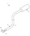
- the flexible treatment instrument 1includes, for example, an insertion portion 2 that is inserted into a patient's body cavity via a forceps channel of an endoscope that is inserted into the patient's body cavity.
- a movable part 4having a treatment part 3 such as a joint and grasping forceps arranged at the distal end of the insertion part 2 and a proximal part of the insertion part 2 and movable by being controlled by a control part (not shown)
- a driving unit 5that operates the unit 4 and a driving wire (driving force transmission member, see FIG. 3) 6 that transmits the driving force generated by the driving unit 5 to the movable unit 4 are provided.
- the insertion part 2is comprised by the medical tube which concerns on one Embodiment of this invention.
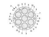
- the medical tube 2includes a tube main body 7 made of a flexible material and a support wire (support member) 8 fixed to the tube main body 7.
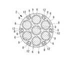
- the tube body 7is constituted by a multi-lumen tube including a plurality of lumens 9 penetrating in the longitudinal direction, and the drive wires 6 are passed through the lumens 9.
- the tube body 7includes seven lumens 9, and FIG. 2 is a longitudinal section in a plane that passes through the central axis of the three lumens 9.
- FIG. 1is a longitudinal section in a plane that passes through the central axis of the three lumens 9.
- the support wire 8is a single wire-like member having a circular cross section and made of a material having a higher Young's modulus than the tube body 7, for example, a metal, a resin, or the like.
- the tube body 7is provided with a through hole (support member lumen) 10 through which the support wire 8 passes.
- the through holes 10are arranged at six positions at intervals in the circumferential direction at positions close to the outer peripheral surface of the tube body 7.
- the diameter of the through hole 10is substantially the same as the outer diameter of the support wire 8 that penetrates the through hole 10. It is desirable that the outer surface of the support wire 8 is in close contact with the inner surface of the through hole 10 by inserting and arranging the support wire 8 in the through hole 10.
- the support wire 8is fixed in the through hole 10 of the tube body 7 with an adhesive.
- the fixing positionmay be fixed over the entire length, or may be fixed only at both ends.
- the lumen 9 of the tube body 7has a circular cross-sectional shape, and the inner diameter dimension thereof is larger than the outer diameter dimension of the support wire 8. Further, the outer diameter dimension of the drive wire 6 is formed larger than the outer diameter dimension of the support wire 8. Further, the through hole 10 for the support wire 8 is disposed between the lumens 9 adjacent to each other in the circumferential direction of the tube body 7.
- the operatorinserts the insertion portion 2 of the flexible treatment tool 1 through the forceps channel of the endoscope inserted into the body cavity of the patient. Is inserted from the side of the movable part 4 at the tip, and the movable part 4 is made to face the affected part while observing an image acquired by the endoscope on the monitor.
- the forceps channel provided in the endoscopeis also bent similarly. ing. Therefore, in order to insert the insertion portion 2 of the flexible treatment instrument 1 through the forceps channel, it is necessary to insert the insertion portion 2 while curving it following the shape of the forceps channel.
- the medical tube 2 constituting the insertion portion of the flexible treatment instrument 1includes a support wire 8 fixed along the longitudinal direction of the tube body 7, and the Young's modulus of the support wire 8 is a tube. It is set to be larger than the Young's modulus of the main body 7. Therefore, the compression rigidity of the medical tube 2 is set sufficiently higher than the compression rigidity of the tube body 7. Further, the bending rigidity with respect to the bending acting on the medical tube 2 is set sufficiently higher than that in the case where the support wire 8 is not provided.
- the medical tube 2 constituting the insertion portion, the tube main body 7 of the medical tube 2, and the tube main body 7are formed.
- the entire insertion portion 2is bent by twisting the lumen 9 and the through hole 10, and the drive wire 6 passing through the lumen 9 and the support wire 8 passing through the through hole 10.
- the operatorgenerates a driving force in the drive unit 5 by operating an operation unit (not shown) and pulls one of the drive wires 6.
- the driving force applied to the drive wire 6is transmitted to the movable part 4 as the tension of the drive wire 6, and the movable part 4 is operated.
- the tube main body 7is positioned in the vicinity of the lumen 9 of the towed drive wire 6.
- a compression forceacts.
- the compression rigidityis enhanced by the support wire 8 fixed to the tube body 7, compression and bending of the tube body 7 due to the pulling of the drive wire 6 is suppressed.
- the cross-sectional shape of the drive wire 6is set larger than that of the support wire 8, the rigidity of the drive wire 6 that drives the movable portion 4 can be increased. There is an advantage that the response during driving can be improved.
- the through-hole 10 which penetrates the support wire 8is arrange
- the support wire 8is arrange
- the support wire 8can be disposed as radially inward as possible while ensuring a sufficient thickness of the tube body 7. Thereby, the diameter of the medical tube 2 can be reduced.
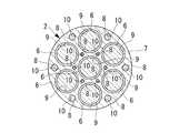
- the support wire 8is comprised with the single wire, there exists an advantage that it can comprise at low cost compared with the case where it comprises with a strand wire. Moreover, rigidity can be improved by comprising with a solid single wire.
- the number of support wires 8is preferably greater than the number of drive wires 6. In this way, bending of the tube body 7 can be suppressed by the large number of support wires 8. Further, the position of the support wire 8 is preferably in the vicinity of the outer periphery of the tube body 7 as shown in FIGS. 3 and 4, but as shown in FIGS. 5 and 6, there is a space between the lumens 9. You may arrange
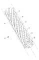
- rumen 11is the longitudinal axis of the tube main body 7, as FIG. 7 shows. It may be formed in a spiral shape having a constant pitch and a constant radius in one direction.
- FIG. 7shows only the lumen 11 provided in the tube main body 7.
- the through-hole 10 through which the support wire 8 passesmay be provided straight along the longitudinal direction of the tube body 7 or twisted in the same direction as the lumen 9 for the drive wire 6. Also good.
- the pitch when the support wire 8 is twistedmay be different from the pitch of the lumen 9 for the drive wire 6 but is preferably the same.
- the tube body 7is provided with the through-hole 10 that allows the support wire 8 to pass therethrough.
- a groove 12 that accommodates the support wire 8is provided. It is good also as fixing with the fixing materials, such as an adhesive agent or resin, in the state which provided and the support wire 8 was accommodated in this groove
- the medical tube 2may include an outer tube that covers the tube body 7.
- the compression rigiditycan be improved while ensuring flexibility.
- a tube made of a braided bodyas the exterior tube, it is possible to improve torque transmission while ensuring flexibility.
- a hydrophilic coated tube or a PTFE tubeas the outer tube, it is possible to reduce surface friction and improve electrical insulation.
- the tube body 7may be made of an electrically insulating material, and the support wire 8 may be made of a conductive material. By doing so, it is possible to supply power and transmit electric signals from the proximal end side of the insertion portion 2 to the movable portion 4 on the distal end side through the support wire 8 insulated by the tube body 7. Since there is no need to prepare a separate electric wiring, there is an advantage that the diameter of the insertion portion 2 can be reduced.
Landscapes
- Health & Medical Sciences (AREA)
- Surgery (AREA)
- Life Sciences & Earth Sciences (AREA)
- Medical Informatics (AREA)
- Animal Behavior & Ethology (AREA)
- Engineering & Computer Science (AREA)
- Biomedical Technology (AREA)
- Heart & Thoracic Surgery (AREA)
- Ophthalmology & Optometry (AREA)
- Molecular Biology (AREA)
- Nuclear Medicine, Radiotherapy & Molecular Imaging (AREA)
- General Health & Medical Sciences (AREA)
- Public Health (AREA)
- Veterinary Medicine (AREA)
- Endoscopes (AREA)
- Surgical Instruments (AREA)
- Media Introduction/Drainage Providing Device (AREA)
Abstract
Description
Translated fromJapanese本発明は、軟性処置具および医療用チューブに関するものである。The present invention relates to a flexible treatment instrument and a medical tube.
挿入部の先端に配置された湾曲部あるいは鉗子等の可動部をワイヤによって駆動する方式の軟性マニピュレータが知られている(例えば、特許文献1参照。)。
特許文献1は、軟性の挿入部の先端に設けられた鉗子等の可動部を駆動するためのワイヤを、挿入部に配置されたマルチルーメンチューブの長手方向に沿って真っ直ぐに形成されたルーメン内に貫通させて案内することで、絶縁皮膜やコイルシースを不要として、細径化および低コスト化を図った軟性マニピュレータを開示している。There is known a soft manipulator that drives a movable portion such as a bending portion or forceps disposed at the distal end of an insertion portion with a wire (see, for example, Patent Document 1).
In Patent Document 1, a wire for driving a movable part such as a forceps provided at the distal end of a flexible insertion part is formed in a lumen formed straight along the longitudinal direction of a multi-lumen tube arranged in the insertion part. A flexible manipulator is disclosed in which an insulating coating or a coil sheath is not required by passing through the guide to reduce the diameter and cost.
特許文献1の軟性マニピュレータは、ワイヤを案内するルーメンが挿入部の長手方向に沿って真っ直ぐに形成されているので、挿入部の湾曲方向によっては、可動部を操作するための2本のワイヤの経路長に差が発生し、一方のワイヤが突っ張って、他方が緩むと、可動部が意図しない方向に移動してしまう。In the soft manipulator of Patent Document 1, since the lumen for guiding the wire is formed straight along the longitudinal direction of the insertion portion, depending on the bending direction of the insertion portion, two wires for operating the movable portion If a difference occurs in the path length and one wire is stretched and the other is loosened, the movable part moves in an unintended direction.
本発明は、上述した事情に鑑みてなされたものであって、細長い駆動力伝達部材によって軟性の挿入部の先端に配置された可動部を挿入部の基端側において操作する場合の操作性あるいは制御する場合の制御性を向上することができる軟性処置具および医療用チューブを提供することを目的としている。The present invention has been made in view of the above-described circumstances, and the operability in the case of operating the movable portion arranged at the distal end of the flexible insertion portion on the proximal end side of the insertion portion by an elongated driving force transmission member or An object of the present invention is to provide a flexible treatment instrument and a medical tube that can improve the controllability in the case of control.
本発明の一態様は、細長い軟性の挿入部と、該挿入部の先端に配置された可動部と、前記挿入部の基端に配置された駆動部と、該駆動部の動力を前記可動部に伝達する細長い駆動力伝達部材とを備え、前記挿入部が、前記駆動力伝達部材を長手方向に貫通させるルーメンを備える医療用チューブを備え、該医療用チューブが、前記ルーメンが形成された長尺のチューブ本体と、該チューブ本体に前記長手方向に沿って固定された前記チューブ本体より高いヤング率を有する1以上のワイヤ状の支持部材とを備える軟性処置具である。One aspect of the present invention includes an elongated flexible insertion portion, a movable portion disposed at a distal end of the insertion portion, a driving portion disposed at a proximal end of the insertion portion, and power of the driving portion. An elongated driving force transmission member that transmits the driving force transmission member, and the insertion portion includes a medical tube having a lumen that penetrates the driving force transmission member in a longitudinal direction. The medical tube has a length in which the lumen is formed. A flexible treatment instrument comprising a tube body having a scale and one or more wire-shaped support members having a higher Young's modulus than the tube body fixed to the tube body along the longitudinal direction.
本態様によれば、挿入部の基端に配置された駆動部を作動させると、発生した動力がルーメン内を貫通している駆動力伝達部材によって、挿入部の先端に配置されている可動部に伝達され、可動部が作動させられる。動力伝達部材に張力が加えられると、該動力伝達部材が貫通するルーメンの部分において医療用チューブに圧縮力が作用するが、チューブ本体の長手方向に沿って固定されたチューブ本体より高いヤング率のワイヤ状の支持部材によって、チューブ本体の圧縮や曲げが抑制される。これにより、他のルーメンを貫通している他の動力伝達部材の張力の変化を抑制することができ、軟性の挿入部の先端に配置された可動部を挿入部の基端側において操作する場合の操作性あるいは制御する場合の制御性を向上することができる。According to this aspect, when the drive unit disposed at the proximal end of the insertion unit is operated, the movable unit disposed at the distal end of the insertion unit by the driving force transmission member in which the generated power passes through the lumen. To move the movable part. When tension is applied to the power transmission member, a compressive force is applied to the medical tube in the portion of the lumen through which the power transmission member passes, but the Young's modulus is higher than that of the tube body fixed along the longitudinal direction of the tube body. The wire-like support member suppresses compression and bending of the tube body. As a result, it is possible to suppress a change in tension of another power transmission member penetrating another lumen, and to operate the movable part arranged at the distal end of the flexible insertion part on the proximal end side of the insertion part It is possible to improve the operability or controllability when controlling.
上記態様においては、前記駆動力伝達部材の外径が前記支持部材の外径より大きくてもよい。
このようにすることで、駆動力伝達部材の剛性を大きく確保することができ、可動部を駆動する際の応答性を向上することができる。In the said aspect, the outer diameter of the said driving force transmission member may be larger than the outer diameter of the said supporting member.
By doing in this way, the rigidity of a driving force transmission member can be ensured largely, and the responsiveness at the time of driving a movable part can be improved.
また、上記態様においては、前記支持部材が、前記ルーメンよりも径方向外方に固定されていてもよい。
このようにすることで、医療用チューブの曲げ剛性を増大させて、駆動力伝達部材に張力がかかったときのルーメンの湾曲を抑制することができる。Moreover, in the said aspect, the said support member may be fixed to radial direction outward rather than the said lumen | rumen.
By doing in this way, the bending rigidity of a medical tube can be increased and the bending of the lumen when tension is applied to the driving force transmission member can be suppressed.
また、上記態様においては、前記ルーメンが周方向に間隔をあけて複数備えられ、前記支持部材が、周方向に隣り合う前記ルーメンの間に配置されていてもよい。
このようにすることで、ルーメンと支持部材との間のチューブ本体の最小肉厚を確保しながら、医療用チューブの外径寸法を小さくすることができる。In the above aspect, a plurality of the lumens may be provided at intervals in the circumferential direction, and the support member may be disposed between the lumens adjacent in the circumferential direction.
By doing in this way, the outer diameter dimension of a medical tube can be made small, ensuring the minimum thickness of the tube main body between a lumen | rumen and a supporting member.
また、上記態様においては、前記支持部材が、単線であってもよい。
このようにすることで、撚り線からなる場合と比較して、支持部材を安価かつ高剛性に構成することができる。In the above aspect, the support member may be a single wire.
By doing in this way, a support member can be comprised cheaply and highly rigid compared with the case where it consists of a strand wire.
また、上記態様においては、前記ルーメンおよび前記支持部材が螺旋状に形成されていてもよい。
このようにすることで、医療用チューブが湾曲したときに、チューブ本体における周方向位置の違いによる経路長差の発生を抑制することができる。In the above aspect, the lumen and the support member may be formed in a spiral shape.
By doing in this way, when a medical tube curves, generation | occurrence | production of the path length difference by the difference in the circumferential direction position in a tube main body can be suppressed.
また、上記態様においては、前記ルーメンおよび前記支持部材の螺旋形状のピッチが等しくてもよい。
このようにすることで、容易に製造することができる。Moreover, in the said aspect, the helical pitch of the said lumen | rumen and the said supporting member may be equal.
By doing in this way, it can manufacture easily.
また、上記態様においては、前記ルーメンが電気的絶縁性材料により構成され、前記支持部材が導電性材料により構成されていてもよい。
このようにすることで、支持部材を利用して通電し、電力供給あるいは電気信号の伝送を行うことができる。In the above aspect, the lumen may be made of an electrically insulating material, and the support member may be made of a conductive material.
By doing in this way, it can supply with electricity using a supporting member, and can perform electric power supply or transmission of an electric signal.
また、上記態様においては、前記チューブ本体に、前記支持部材を貫通させる支持部材用ルーメンが設けられ、前記支持部材が、前記支持部材用ルーメン内に収容されていてもよい。
また、上記態様においては、前記チューブ本体の外周面に、前記支持部材を収容する溝が設けられ、前記支持部材が、前記溝内に固定されていてもよい。Moreover, in the said aspect, the lumen for support members which penetrates the said support member in the said tube main body is provided, and the said support member may be accommodated in the said lumen for support members.
Moreover, in the said aspect, the groove | channel which accommodates the said supporting member may be provided in the outer peripheral surface of the said tube main body, and the said supporting member may be fixed in the said groove | channel.
また、上記態様においては、前記挿入部が、前記医療用チューブの外周を被覆する外装チューブを備えていてもよい。
このようにすることで、可撓性を有しつつ、圧縮剛性や捻り剛性等の性能を外装チューブによって付加することができる。Moreover, in the said aspect, the said insertion part may be provided with the exterior tube which coat | covers the outer periphery of the said medical tube.
By doing in this way, performance, such as compression rigidity and torsional rigidity, can be added with an exterior tube, having flexibility.
また、本発明の他の態様は、細長い軟性の挿入部と、該挿入部の先端に配置された可動部と、前記挿入部の基端に配置された駆動部と、該駆動部の動力を前記可動部に伝達する細長い駆動力伝達部材とを備える軟性処置具に用いられ、前記駆動力伝達部材を長手方向に貫通させるルーメンを備える長尺のチューブ本体と、該チューブ本体に前記長手方向に沿って固定された前記チューブ本体より高いヤング率を有する1以上のワイヤ状の支持部材とを備える医療用チューブである。In another aspect of the present invention, an elongated flexible insertion portion, a movable portion disposed at a distal end of the insertion portion, a drive portion disposed at a proximal end of the insertion portion, and power of the drive portion are provided. A long tube body used in a flexible treatment instrument including an elongate driving force transmission member that transmits to the movable part, and having a lumen that penetrates the driving force transmission member in the longitudinal direction, and the tube body in the longitudinal direction. It is a medical tube provided with one or more wire-shaped support members which have a higher Young's modulus than the tube main body fixed along.
本発明によれば、細長い駆動力伝達部材によって軟性の挿入部の先端に配置された可動部を挿入部の基端側において操作する場合の操作性あるいは制御する場合の制御性を向上することができるという効果を奏する。According to the present invention, it is possible to improve the operability when operating the movable portion arranged at the distal end of the flexible insertion portion on the proximal end side of the insertion portion or the controllability when controlling by the elongated driving force transmission member. There is an effect that can be done.
本発明の一実施形態に係る軟性処置具1および医療用チューブ2について、図面を参照して以下に説明する。
本実施形態に係る軟性処置具1は、図1に示されるように、例えば、患者の体腔内に挿入される内視鏡の鉗子チャネルを介して患者の体腔内に挿入される挿入部2と、該挿入部2の先端に配置された関節および把持鉗子等の処置部3を有する可動部4と、挿入部2の基端に配置され、制御部(図示略)によって制御されることにより可動部4を作動させる駆動部5と、該駆動部5により発生した駆動力を可動部4に伝達する駆動ワイヤ(駆動力伝達部材、図3参照。)6とを備えている。A flexible treatment instrument 1 and a
As shown in FIG. 1, the flexible treatment instrument 1 according to the present embodiment includes, for example, an
挿入部2は、本発明の一実施形態に係る医療用チューブにより構成されている。
医療用チューブ2は、図2および図3に示されるように、可撓性材料からなるチューブ本体7と、該チューブ本体7に固定された支持ワイヤ(支持部材)8とを備えている。
チューブ本体7は、長手方向に貫通する複数のルーメン9を備えるマルチルーメンチューブにより構成され、各ルーメン9に駆動ワイヤ6を貫通させるようになっている。本実施形態においては、図3に示されるように、チューブ本体7は、7本のルーメン9を備えており、図2はその内の3本のルーメン9の中心軸を通る平面での縦断面図である。The
As shown in FIGS. 2 and 3, the
The
支持ワイヤ8は、チューブ本体7よりヤング率の高い材質、例えば、金属、樹脂等により構成された、横断面円形の単線のワイヤ状の部材である。
チューブ本体7には、図2および図3に示されるように、支持ワイヤ8を貫通させる貫通孔(支持部材用ルーメン)10が設けられている。貫通孔10は、図3に示す例では、チューブ本体7の外周面に近い位置に周方向に間隔をあけて、6箇所に配置されている。貫通孔10の口径は、内部に貫通させられる支持ワイヤ8の外径寸法と略同等である。貫通孔10に支持ワイヤ8が挿入配置されることにより、支持ワイヤ8の外面は貫通孔10の内面に密着していることが望ましい。The
As shown in FIGS. 2 and 3, the
支持ワイヤ8は、チューブ本体7の貫通孔10内に接着剤により固定されている。固定位置は、全長にわたって固定されていてもよいし、両端のみにおいて固定されていてもよい。
チューブ本体7のルーメン9は円形の横断面形状を有し、その内径寸法は、支持ワイヤ8の外径寸法より大きく構成されている。また、駆動ワイヤ6の外径寸法は支持ワイヤ8の外径寸法より大きく形成されている。
さらに、支持ワイヤ8用の貫通孔10は、チューブ本体7の周方向に隣り合うルーメン9の間に配置されている。The
The
Further, the through
このように構成された本実施形態に係る軟性処置具1および医療用チューブ2の作用について、以下に説明する。
本実施形態に係る軟性処置具1を用いて患者の体腔内の処置を行うには、オペレータは、患者の体腔内に挿入した内視鏡の鉗子チャネルを介して軟性処置具1の挿入部2を先端の可動部4側から挿入し、内視鏡により取得された画像をモニタで観察しながら患部に対して可動部4を対向させる。The operation of the flexible treatment instrument 1 and the
In order to perform treatment in the body cavity of the patient using the flexible treatment tool 1 according to the present embodiment, the operator inserts the
この場合において、内視鏡は、患者の曲がりくねった臓器の形状に沿うように湾曲させられて、患者の体内に配置されているので、該内視鏡に設けられた鉗子チャネルも同様に湾曲している。したがって、鉗子チャネルを介して軟性処置具1の挿入部2を挿入するには、挿入部2を鉗子チャネルの形状に倣わせて湾曲させながら挿入する必要がある。In this case, since the endoscope is curved so as to conform to the shape of the patient's tortuous organ and is disposed in the patient's body, the forceps channel provided in the endoscope is also bent similarly. ing. Therefore, in order to insert the
本実施形態においては、軟性処置具1の挿入部を構成している医療用チューブ2が、チューブ本体7の長手方向に沿って固定された支持ワイヤ8を備え、支持ワイヤ8のヤング率がチューブ本体7のヤング率より大きく設定されている。したがって、医療用チューブ2の圧縮剛性は、チューブ本体7の圧縮剛性よりも十分に高く設定されている。また、医療用チューブ2に作用する曲げに対する曲げ剛性は、支持ワイヤ8を有しない場合よりも十分に高く設定されている。In the present embodiment, the
したがって、挿入部2を曲げながら鉗子チャネル内に挿入していく際には、挿入部を構成している医療用チューブ2、該医療用チューブ2のチューブ本体7、該チューブ本体7に形成されたルーメン9および貫通孔10、ルーメン9内を貫通している駆動ワイヤ6および貫通孔10を貫通している支持ワイヤ8が捻られることにより、挿入部2全体が湾曲させられる。Therefore, when inserting into the forceps channel while bending the
次いで、オペレータは、図示しない操作部を操作することにより駆動部5に駆動力を発生させ、いずれかの駆動ワイヤ6を牽引する。駆動ワイヤ6に加えられた駆動力は駆動ワイヤ6の張力として可動部4に伝達され、可動部4が作動させられる。Next, the operator generates a driving force in the
この場合において、本実施形態に係る軟性処置具1および医療用チューブ2によれば、いずれかの駆動ワイヤ6を牽引する際には、牽引された駆動ワイヤ6のルーメン9近傍においてチューブ本体7に圧縮力が作用する。本実施形態によれば、チューブ本体7に固定された支持ワイヤ8によって、圧縮剛性が高められているので、駆動ワイヤ6の牽引によるチューブ本体7の圧縮や曲げが抑制される。
その結果、駆動したい関節とは異なる関節が意図せず動いてしまう不都合の発生を抑制することができるという利点がある。In this case, according to the flexible treatment instrument 1 and the
As a result, there is an advantage that it is possible to suppress the occurrence of inconvenience that a joint different from the joint to be driven moves unintentionally.
また、本実施形態によれば、支持ワイヤ8より駆動ワイヤ6の横断面形状を大きく設定しているので、可動部4を駆動する駆動ワイヤ6の剛性を大きくすることができ、可動部4の駆動時の応答性を向上することができるという利点がある。Further, according to the present embodiment, since the cross-sectional shape of the
また、本実施形態によれば、支持ワイヤ8を貫通させる貫通孔10が、チューブ本体7の外周面に近い位置に配置されているので、支持ワイヤ8により、より効果的に曲げ剛性を向上することができる。これにより、チューブ本体7に設けられたルーメン9の曲げを抑制することができる。Moreover, according to this embodiment, since the through-
また、本実施形態によれば、支持ワイヤ8が、チューブ本体7に設けられた周方向に隣り合うルーメン9の間に配置されているので、横断面円形のルーメン9の間に形成されるスペースに、チューブ本体7の十分な肉厚を確保しながら支持ワイヤ8を可能な限り径方向内方に配置することができる。これにより、医療用チューブ2の細径化を図ることができる。Moreover, according to this embodiment, since the
また、本実施形態によれば、支持ワイヤ8が、単線により構成されているので、撚り線により構成する場合と比較して安価に構成することができるという利点がある。また、中実の単線により構成することで、剛性を高めることができる。Moreover, according to this embodiment, since the
なお、本実施形態においては、支持ワイヤ8の本数は駆動ワイヤ6の本数より多いことが好ましい。このようにすることで、多数の支持ワイヤ8によってチューブ本体7の曲げを抑制することができる。また、支持ワイヤ8の位置は、図3および図4に示されるように、チューブ本体7の外周近傍であることが好ましいが、図5および図6に示されるように、ルーメン9の間にスペースが確保し得る任意の位置に配置してもよい。In the present embodiment, the number of
また、本実施形態においては、チューブ本体7が、直線状のルーメン9を有する場合を例示したが、これに代えて、図7に示されるように、各ルーメン11が、チューブ本体7の長手軸回りに、一方向に一定のピッチおよび一定の半径で捻られた螺旋状に形成されていてもよい。図7は、チューブ本体7に設けられたルーメン11のみを表示したものである。
このようにすることで、チューブ本体7が湾曲されたときの周方向位置の違いによるルーメン11間の経路長差の発生を抑制することができるという利点がある。Moreover, in this embodiment, although the case where the tube
By doing in this way, there exists an advantage that generation | occurrence | production of the path | route length difference between the
また、この場合に、支持ワイヤ8を貫通させる貫通孔10は、チューブ本体7の長手方向に沿って真っ直ぐに設けられていてもよいし、駆動ワイヤ6用のルーメン9と同一方向に捻れていてもよい。支持ワイヤ8が捻れている場合のピッチは、駆動ワイヤ6用のルーメン9のピッチとは異なっていてもよいが同じであることが好ましい。このようにすることで、押し出し成形によって製造する場合に、製造を容易にすることができるという利点がある。Further, in this case, the through-
また、本実施形態においては、チューブ本体7に支持ワイヤ8を貫通させる貫通孔10を設けることとしたが、これに代えて、図8に示されるように、支持ワイヤ8を収容する溝12を設け、該溝12内に支持ワイヤ8を収容した状態で、接着剤あるいは樹脂等の固定材によって固定することとしてもよい。In the present embodiment, the
また、本実施形態においては、医療用チューブ2が、チューブ本体7を被覆する外装チューブを備えることにしてもよい。
例えば、外装チューブとしてコイルチューブを使用することにより、可撓性を確保しつつ圧縮剛性を向上することができる。In the present embodiment, the
For example, by using a coil tube as the outer tube, the compression rigidity can be improved while ensuring flexibility.
また、例えば、外装チューブとして編組体からなるチューブを使用することにより、可撓性を確保しつつトルク伝達性を向上することができる。
さらに、例えば、外装チューブとして親水性コートチューブやPTFEチューブを用いることにより、表面の摩擦の低減や電気的絶縁性の向上を図ることができる。Further, for example, by using a tube made of a braided body as the exterior tube, it is possible to improve torque transmission while ensuring flexibility.
Furthermore, for example, by using a hydrophilic coated tube or a PTFE tube as the outer tube, it is possible to reduce surface friction and improve electrical insulation.
また、本実施形態においては、チューブ本体7を電気的絶縁性材料により構成し、支持ワイヤ8を導電性材料により構成することにしてもよい。
このようにすることで、チューブ本体7によって絶縁された支持ワイヤ8を介して、挿入部2の基端側から先端側の可動部4まで電力供給や電気信号の伝達を図ることができる。別途電気配線を用意する必要がないので、挿入部2を細径化することができるという利点がある。In the present embodiment, the
By doing so, it is possible to supply power and transmit electric signals from the proximal end side of the
1 軟性処置具
2 挿入部(医療用チューブ)
4 可動部
5 駆動部
6 駆動ワイヤ(駆動力伝達部材)
7 チューブ本体
8 支持ワイヤ(支持部材)
9,11 ルーメン
10 貫通孔(支持部材用ルーメン)
12 溝1
4
7
9,11
12 grooves
Claims (12)
Translated fromJapanese該挿入部の先端に配置された可動部と、
前記挿入部の基端に配置された駆動部と、
該駆動部の動力を前記可動部に伝達する細長い駆動力伝達部材とを備え、
前記挿入部が、前記駆動力伝達部材を長手方向に貫通させるルーメンを備える医療用チューブを備え、
該医療用チューブが、前記ルーメンが形成された長尺のチューブ本体と、該チューブ本体に前記長手方向に沿って固定された前記チューブ本体より高いヤング率を有する1以上のワイヤ状の支持部材とを備える軟性処置具。An elongated flexible insert,
A movable part disposed at the tip of the insertion part;
A drive unit disposed at a proximal end of the insertion unit;
An elongate driving force transmission member that transmits the power of the driving unit to the movable unit;
The insertion portion includes a medical tube including a lumen that penetrates the driving force transmission member in a longitudinal direction;
The medical tube includes a long tube body in which the lumen is formed, and one or more wire-shaped support members having a higher Young's modulus than the tube body fixed to the tube body along the longitudinal direction; A flexible treatment device comprising:
前記支持部材が、周方向に隣り合う前記ルーメンの間に配置されている請求項1から請求項3のいずれかに記載の軟性処置具。A plurality of the lumens are provided at intervals in the circumferential direction,
The flexible treatment tool according to any one of claims 1 to 3, wherein the support member is disposed between the lumens adjacent in the circumferential direction.
前記支持部材が、前記支持部材用ルーメン内に収容されている請求項1から請求項8のいずれかに記載の軟性処置具。The tube body is provided with a support member lumen that penetrates the support member,
The flexible treatment instrument according to any one of claims 1 to 8, wherein the support member is accommodated in the lumen for the support member.
前記支持部材が、前記溝内に固定されている請求項1から請求項8のいずれかに記載の軟性処置具。A groove for accommodating the support member is provided on the outer peripheral surface of the tube body,
The flexible treatment tool according to any one of claims 1 to 8, wherein the support member is fixed in the groove.
前記駆動力伝達部材を長手方向に貫通させるルーメンを備える長尺のチューブ本体と、該チューブ本体に前記長手方向に沿って固定された前記チューブ本体より高いヤング率を有する1以上のワイヤ状の支持部材とを備える医療用チューブ。An elongated flexible insertion portion, a movable portion disposed at the distal end of the insertion portion, a drive portion disposed at the proximal end of the insertion portion, and an elongated drive force transmission that transmits power of the drive portion to the movable portion Used in a flexible treatment instrument comprising a member,
A long tube body having a lumen that penetrates the driving force transmission member in the longitudinal direction, and one or more wire-like supports having a higher Young's modulus than the tube body fixed to the tube body along the longitudinal direction A medical tube comprising a member.
Priority Applications (2)
| Application Number | Priority Date | Filing Date | Title |
|---|---|---|---|
| JP2018503946AJPWO2017154172A1 (en) | 2016-03-10 | 2016-03-10 | Flexible treatment device and medical tube |
| PCT/JP2016/057587WO2017154172A1 (en) | 2016-03-10 | 2016-03-10 | Flexible treatment instrument and medical tube |
Applications Claiming Priority (1)
| Application Number | Priority Date | Filing Date | Title |
|---|---|---|---|
| PCT/JP2016/057587WO2017154172A1 (en) | 2016-03-10 | 2016-03-10 | Flexible treatment instrument and medical tube |
Publications (1)
| Publication Number | Publication Date |
|---|---|
| WO2017154172A1true WO2017154172A1 (en) | 2017-09-14 |
Family
ID=59790296
Family Applications (1)
| Application Number | Title | Priority Date | Filing Date |
|---|---|---|---|
| PCT/JP2016/057587CeasedWO2017154172A1 (en) | 2016-03-10 | 2016-03-10 | Flexible treatment instrument and medical tube |
Country Status (2)
| Country | Link |
|---|---|
| JP (1) | JPWO2017154172A1 (en) |
| WO (1) | WO2017154172A1 (en) |
Citations (7)
| Publication number | Priority date | Publication date | Assignee | Title |
|---|---|---|---|---|
| JPH05345031A (en)* | 1992-06-16 | 1993-12-27 | Tougou Medeikitsuto Kk | Catheter |
| WO2007096951A1 (en)* | 2006-02-21 | 2007-08-30 | Olympus Medical Systems Corp. | Endoscope system and medical instrument |
| JP2009530051A (en)* | 2006-03-23 | 2009-08-27 | ボストン サイエンティフィック リミテッド | Medical devices and systems |
| JP2012034971A (en)* | 2010-08-10 | 2012-02-23 | Japan Lifeline Co Ltd | Catheter |
| WO2013011771A1 (en)* | 2011-07-15 | 2013-01-24 | オリンパスメディカルシステムズ株式会社 | Insertion instrument |
| JP2014236788A (en)* | 2013-06-06 | 2014-12-18 | 日本ライフライン株式会社 | Electrode catheter system |
| WO2015093602A1 (en)* | 2013-12-20 | 2015-06-25 | オリンパス株式会社 | Guide member for flexible manipulator, and flexible manipulator |
- 2016
- 2016-03-10WOPCT/JP2016/057587patent/WO2017154172A1/ennot_activeCeased
- 2016-03-10JPJP2018503946Apatent/JPWO2017154172A1/enactivePending
Patent Citations (7)
| Publication number | Priority date | Publication date | Assignee | Title |
|---|---|---|---|---|
| JPH05345031A (en)* | 1992-06-16 | 1993-12-27 | Tougou Medeikitsuto Kk | Catheter |
| WO2007096951A1 (en)* | 2006-02-21 | 2007-08-30 | Olympus Medical Systems Corp. | Endoscope system and medical instrument |
| JP2009530051A (en)* | 2006-03-23 | 2009-08-27 | ボストン サイエンティフィック リミテッド | Medical devices and systems |
| JP2012034971A (en)* | 2010-08-10 | 2012-02-23 | Japan Lifeline Co Ltd | Catheter |
| WO2013011771A1 (en)* | 2011-07-15 | 2013-01-24 | オリンパスメディカルシステムズ株式会社 | Insertion instrument |
| JP2014236788A (en)* | 2013-06-06 | 2014-12-18 | 日本ライフライン株式会社 | Electrode catheter system |
| WO2015093602A1 (en)* | 2013-12-20 | 2015-06-25 | オリンパス株式会社 | Guide member for flexible manipulator, and flexible manipulator |
Also Published As
| Publication number | Publication date |
|---|---|
| JPWO2017154172A1 (en) | 2019-01-10 |
Similar Documents
| Publication | Publication Date | Title |
|---|---|---|
| US11730551B2 (en) | Steerable medical device with strain relief elements | |
| JP6261612B2 (en) | Guide member for soft manipulator and soft manipulator | |
| JP5981080B1 (en) | Endoscope bending tube and endoscope provided with the endoscope bending tube | |
| US10149608B2 (en) | Bending portion for endoscope and endoscope including bending portion for endoscope | |
| JP5711434B1 (en) | Endoscope | |
| CN113812900A (en) | Endoscope comprising an articulated bending section body | |
| WO2016194249A1 (en) | Medical manipulator | |
| JP5114179B2 (en) | Bipolar high-frequency treatment instrument for endoscope | |
| WO2016056417A1 (en) | Endoscope | |
| CN113873948B (en) | Medical tool positioning device, system, and methods of use and manufacture | |
| JP6271098B1 (en) | Medical overtube | |
| JP2007289593A5 (en) | ||
| JP6296869B2 (en) | Treatment instrument and surgical system | |
| JPWO2017175373A1 (en) | Flexible manipulator | |
| JP6637991B2 (en) | Medical equipment | |
| WO2017154172A1 (en) | Flexible treatment instrument and medical tube | |
| WO2019207676A1 (en) | Treatment instrument and treatment system | |
| WO2018216109A1 (en) | Flexible manipulator | |
| US11660421B2 (en) | Medical manipulator and medical device | |
| WO2020021718A1 (en) | Endoscope | |
| JPWO2021176719A5 (en) | ||
| JP2016511120A (en) | Multiconductor guidewire with chordal surface | |
| JPH11267091A (en) | Endoscope insertion section | |
| JP2013172781A (en) | Tubular instrument |
Legal Events
| Date | Code | Title | Description |
|---|---|---|---|
| ENP | Entry into the national phase | Ref document number:2018503946 Country of ref document:JP Kind code of ref document:A | |
| NENP | Non-entry into the national phase | Ref country code:DE | |
| 121 | Ep: the epo has been informed by wipo that ep was designated in this application | Ref document number:16893501 Country of ref document:EP Kind code of ref document:A1 | |
| 122 | Ep: pct application non-entry in european phase | Ref document number:16893501 Country of ref document:EP Kind code of ref document:A1 |