WO2017150514A1 - Suture device - Google Patents
Suture deviceDownload PDFInfo
- Publication number
- WO2017150514A1 WO2017150514A1PCT/JP2017/007734JP2017007734WWO2017150514A1WO 2017150514 A1WO2017150514 A1WO 2017150514A1JP 2017007734 WJP2017007734 WJP 2017007734WWO 2017150514 A1WO2017150514 A1WO 2017150514A1
- Authority
- WO
- WIPO (PCT)
- Prior art keywords
- needle
- needle insertion
- arm
- front arm
- rear arm
- Prior art date
- Legal status (The legal status is an assumption and is not a legal conclusion. Google has not performed a legal analysis and makes no representation as to the accuracy of the status listed.)
- Ceased
Links
Images


Classifications
- A—HUMAN NECESSITIES
- A61—MEDICAL OR VETERINARY SCIENCE; HYGIENE
- A61B—DIAGNOSIS; SURGERY; IDENTIFICATION
- A61B17/00—Surgical instruments, devices or methods
- A61B17/04—Surgical instruments, devices or methods for suturing wounds; Holders or packages for needles or suture materials
Definitions
- the present inventionrelates to a suturing device. More specifically, transluminal endoscopic surgery is performed to form a through-hole in the digestive tract or an intraperitoneal operation with a flexible endoscope inserted into the body through a natural hole such as the mouth, anus, or vaginal opening.
- the present inventionrelates to a suturing device used for the above.
- Transluminal endoscopic surgery(hereinafter referred to as NOTES) is the removal of lesions in the digestive tract cavity and the abdominal cavity with a soft endoscope inserted into the body through natural holes such as the mouth, anus, and vaginal opening. Surgery to perform this procedure.
- a soft endoscopeis inserted from the mouth, and a hole is formed in the stomach wall by the tip of the soft endoscope, and the tip of the soft endoscope is infiltrated into the abdominal cavity from this hole, and is formed in the pancreas, liver, etc.
- An operation for removing a tumor or the like with a flexible endoscopealso corresponds to NOTES.
- the present inventionhas been made in view of such a situation, and an object of the present invention is to provide an endoscopic suturing device in which a suture is difficult to come off from the suturing device when the suturing device is inserted into the body.
- a suturing devicecomprises: A suturing device used by being inserted into the body while attached to an endoscope, The front arm, A rear arm provided so as to be able to approach and separate from the front arm, The rear arm includes at least one needle-like member, The front arm is provided with at least two needle insertion portions that can accommodate the tip of the needle-like member when the front arm and the rear arm approach each other, In each of the needle insertion portions, an engagement member that can be engaged with the needle-like member is detachably accommodated in each of the needle insertion portions, At least one set of the engaging members housed in each of the needle insertion portions is connected to each other by a suture, The engagement member includes a drop-off preventing member configured to prevent the engagement member from dropping from the needle insertion portion until the needle-like member is inserted into the needle insertion portion.
- the engagement member or a part of the suture threadfalls off by the fall-off preventing member so that the engagement member does not fall off from the needle insertion portion. It has been prevented. Therefore, even when the suturing device is inserted into the body, the suture is difficult to come off from the suturing device.
- the suturing device of the present inventionis used, the wound can be sutured to the same extent as the surgical operation by the endoscope inserted into the digestive tract cavity.
- the drop-off prevention memberhas a film for preventing the engagement member from dropping from the needle insertion portion, and the film is positioned around the needle insertion portion so as to cover the needle insertion portion. You may adhere
- the drop-off preventing member(the film) may be broken or peeled off from the surface of the front arm with a predetermined force or more.
- the predetermined forceis a force when the needle-like member is inserted into the engagement member, or after the needle-like member is inserted into the engagement member, the needle-like member is inserted together with the engagement member into the needle insertion portion. It is the force when pulling out from.
- the drop-off prevention memberhas a resin for temporarily fixing the engagement member to the needle insertion portion, and the resin contains a hole in which the engagement member or a part of the suture is accommodated. A part of the groove or the recess may be filled.
- the drop-off prevention member(the resin) is temporarily fixed to the engagement member or a part of the suture and the needle insertion portion so as to be broken or separated by a predetermined force or more. Also good.
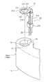
- FIG. 1is a schematic explanatory view of a main part of an endoscope provided with a suturing device according to an embodiment of the present invention.
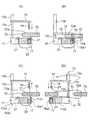
- 2Ais an enlarged plan view of a main part of the IIA collar shown in FIG. 2B is a perspective view of a main part of the yarn assembly and the needle insertion portion shown in FIG. 2A.
- 2Cis a cross-sectional view of a principal part taken along the line IIC-IIC shown in FIG. 2A.
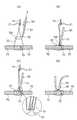
- FIG. 3is a sectional view taken along line III-III shown in FIG. 4 (A) to 4 (D) are schematic explanatory views showing an example of use of the suturing device shown in FIG.
- 5 (A) to 5 (D)are schematic explanatory views showing an example of use of the suturing device showing a step subsequent to FIG. 4 (D).
- 6 (A) to 6 (D)are schematic explanatory views showing an example of use of the suturing device showing a continuation process of FIG. 5 (D).
- the suturing device of this embodimentis a device used for suturing an incision or the like formed in an abdominal organ or digestive tract, and is a transluminal endoscopic operation using a flexible endoscope.
- NOTEStransluminal endoscopic operation using a flexible endoscope.
- the suturing devicecan be used by being attached to the distal end of a rigid endoscope such as a laparoscope as well as a flexible endoscope.
- a rigid endoscopesuch as a laparoscope
- a flexible endoscopeit is formed in NOTES for excision of a tumor from excision of a tumor or the like with only the flexible endoscope placed in the digestive tract cavity. Therefore, it is possible to perform an operation without forming a wound on the body surface.
- the suturing device 10 of the present embodimentis attached to the endoscope 1.
- the endoscope 1is a flexible endoscope used for general endoscopic surgery. As long as the endoscope 1 is used by being inserted into the digestive tract of a living body, the diameter, length, material, and the like of the shaft 2 are not particularly limited.
- the diameter of the shaft 2is about 10 mm in a general endoscope, but may be about 5 to 15 mm.
- the length of the shaft 2is about 1200 mm in a general endoscope, but may be about 1200 to 3000 mm.
- the endoscope 1when performing surgery on an organ in the abdominal cavity, is preferably provided with a function such as a narrow-band light observation (NBI) function and a water jet.
- a functionsuch as a narrow-band light observation (NBI) function and a water jet.
- NBInarrow-band light observation
- the suturing device 10 of the present embodimentincludes a pair of front and rear arms 11 and 12 and an arm moving means 13 that operates the pair of front and rear arms 11 and 12.
- the front-rear directionmeans the up-down direction in FIG. 1 and coincides with the longitudinal direction of the arm moving means 13. Further, the front and rear front directions coincide with the lower direction in FIG. 1 and mean the front of the endoscope 1.
- the suturing device 10 of the present embodimentis used by being fixed to the endoscope 1 by fixing the arm moving means 13 to the shaft 2 of the endoscope 1.
- both the pair of front and rear arms 11 and 12are positioned in front of the front end surface 1s of the shaft 2 of the endoscope 1, and the rear arm 12 is inward of the front arm 11. It is used by being attached to the shaft 2 of the endoscope 1 so as to be positioned on the distal end surface 1s side of the endoscope 1.
- the suturing device 10 of the present embodimentis attached so that the axial directions of the tubes 13a to 13c of the arm moving means 13, which will be described later, and the axial direction of the shaft 2 are substantially parallel. Therefore, while confirming the movement of the pair of front and rear arms 11 and 12 with the camera of the endoscope 1, the pair of front and rear arms 11 and 12 are used to remove the incision formed in the digestive tract such as the stomach. Can be sutured.
- the arm moving means 13can smoothly operate the pair of front and rear arms 11 and 12, In addition, the operator can easily operate the pair of front and rear arms 11 and 12. Since the arm moving means 13 can reliably follow the bending of the shaft 2 when the shaft 2 is bent, the arm moving means 13 can be prevented from interfering with the bending of the shaft 2.
- the arm moving means 13is not necessarily provided along the shaft 2 of the endoscope 1, and only the distal end portion of the arm moving means 13 may be fixed to the distal end portion of the shaft 2. Even in this case, if the axial direction of the arm moving means 13 and the axial direction of the distal end portion of the shaft 2 are substantially parallel at the distal end portion of the shaft 2, the operator can operate the pair of front and rear arms 11 and 12. Can be easily.
- the heel arm moving means 13is a long member extending along the axial direction, and is attached to the shaft 2 of the endoscope 1.
- the length of the arm moving means 13is not particularly limited as long as it is approximately the same length as the length of the shaft 2 of the endoscope 1.
- This arm moving means 13is fixed to the shaft 2.
- the arm moving unit 13is fixed with the arm moving unit 13 along the shaft 2 or only the tip of the arm moving unit 13 is fixed to the tip of the shaft 2. It is fixed to the shaft 2.
- the method for fixing the arm moving means 13 to the shaft 2is not particularly limited as long as it can be fixed so as not to prevent deformation of the shaft 2 such as bending.
- itcan be fixed by a belt-like member made of polyethylene, polyvinyl chloride, reinforced plastic, aluminum or the like, or a ring-shaped fastener made of polyethylene, reinforced vinyl, metal or the like, but is not particularly limited.
- the arm moving means 13is formed so as to be flexible enough to follow the bending of the shaft 2 while being fixed to the shaft 2. That is, the arm moving means 13 is formed with a strength that does not hinder the operation of the endoscope 1 even if it is attached to the shaft 2 of the endoscope 1.
- the arm moving means 13is composed of three tubes (or two tubes and wires) having such flexibility that they can be bent following the bending of the shaft 2. That is, the arm moving means 13 is formed by the case tube 13a, the rear arm moving tube 13b, and the front arm moving tube 13c (or the front arm moving wire).
- the scissors case tube 13ais a hollow tube-like member fixed to the shaft 2, and is fixed to the shaft 2 by a belt-like member or the like.
- the material of this case tube 13ais not specifically limited, For example, it is preferable that it is formed with materials, such as polyethylene and a polyvinyl chloride.
- the rear arm moving tube 13bis a hollow tube-like member inserted into the case tube 13a, and is arranged in the case tube 13a so as to be movable along its axial direction and rotatable about the axis. ing.
- the rear arm 12is connected to the tip of the rear arm moving tube 13b.
- the material of the rear arm moving tube 13bis not particularly limited. For example, it is preferably made of a material such as polyethylene, polyvinyl chloride, or metal.
- the rear arm moving tube 13bsince the rear arm moving tube 13b is rotated to swing the rear arm 12, the rear arm moving tube 13b has a rotation amount when the rear arm moving tube 13b is rotated on the hand side. It is preferable that the rear arm 12 can be swung by the same amount.
- the rear arm moving tube 13bis formed by forming a tubular member with a plurality of metal wires arranged so that the axial directions are parallel to each other and coaxially arranged, the above-described functions can be satisfied. It can be.
- the front arm moving tube 13cis a tube inserted into the rear arm moving tube 13b, and is arranged in the rear arm moving tube 13b so as to be movable along its axial direction and rotatable about the axis. ing.
- the front arm 11is connected to the tip of the front arm moving tube 13c.
- the material of the front arm moving tube 13cis not particularly limited, but it is preferable that the tip portion has a rigidity of about 10 mm and is softer on the proximal side than the tip portion, but does not contract or expand in the forward and backward directions.
- a rod-shaped portion with high rigidity formed of metal or the like at the tip of about 10 mm, and a portion other than that portion formed of a wire or the likecan be used as the front arm moving tube 13c.
- the front arm moving tube 13csince the front arm moving tube 13c is rotated to swing the rear arm 12, the front arm moving tube 13c is the same as the amount of rotation when the rear arm moving tube 13b is rotated on the hand side. It is preferable that the rear arm 12 can be swung.
- the proximal end of the front arm moving tube 13c and the proximal end of the rear arm moving tube 13bextend to the vicinity of the operation unit that operates the shaft 2 of the endoscope 1. For this reason, by operating the base end of each tube, the movement of the tip of each tube (advancement / retraction along the axial direction, rotation around the axis) can be operated.
- the arm moving means 13has the above-described configuration, if the front arm moving tube 13c and the rear arm moving tube 13b are moved at the same time or one of them along the axial direction, The pair of arms 11 and 12 can be moved closer to and away from each other.
- the front arm moving tube 13cis rotated around its axis
- the front arm 11can be rotated around the axis of the front arm moving tube 13c
- the rear arm moving tube 13bcan be rotated around the axis.
- the rear arm 12can be rotated around the axis of the rear arm moving tube 13b.
- the front arm moving tube 13conly needs to be able to move relative to the rear arm moving tube 13b in the axial direction, and rotates about its axis with respect to the rear arm moving tube 13b. It may not be possible to make it. In this case, there is an advantage that the central axis of the needle-like member 14 of the rear arm 12 (to be described later) and the central axis of the needle insertion portion 16 of the front arm 11 can always be matched.
- the rear arm moving tube 13bonly needs to be relatively movable along the axial direction with respect to the case tube 13a, and cannot be rotated around its axis with respect to the case tube 13a. May be.
- both the rear arm moving tube 13b and the front arm moving tube 13ccan move independently in the axial direction, but the pair of front and rear arms 11 and 12 can be moved closer to and away from each other. If possible, only one of them may be configured to move in the axial direction.
- the outer diameter of the arm moving means 13(that is, the outer diameter of the case tube 13a) can be inserted into the digestive tract (or into the overtube) of the endoscope 1 to which the suturing device 10 of this embodiment is attached.
- the degreeis not particularly limited.
- the outer diameter of the arm moving means 13is preferably about 11 to 13 mm, more preferably about 11 to 12 mm, which is the combined outer diameter of the arm moving means 13 and the shaft 2.
- the rear arm 12is a member formed in a substantially strip shape, and the front surface 12a and the back surface 12b are formed on flat surfaces parallel to each other.
- the distal end of the rear arm moving tube 13bis connected to the base end portion of the rear arm 12.
- the rear arm moving tube 13bis connected to the rear arm 12 so that the central axis of the rear arm moving tube 13b is orthogonal to the front surface 12a and the back surface 12b of the rear arm 12 at the connecting portion with the rear arm 12.
- the central axis of the rear arm moving tube 13b at the connecting portion of the rear arm moving tube 13b and the rear arm 12is simply referred to as the central axis of the tip of the rear arm moving tube 13b.
- a through hole 12his formed at the base end of the rear arm 12 so as to penetrate between the front surface 12a and the back surface 12b.
- the central axis of the distal end of the rear arm moving tube 13bis the center of the through hole 12h. The reason why it is arranged so as to be substantially coaxial with the shaft will be described later.
- a needle-like member 14is provided at the tip of the rear arm 12.
- the needle-like member 14has a shaft portion 14b and a portion having a large outer diameter (a ridge portion 14a) at the tip provided at the tip of the shaft portion 14b.
- the edge portion 14ais formed so that the outer diameter of the base end thereof is larger than the outer diameter of the tip end of the shaft portion 14b, and a step is formed at the connecting portion with the shaft portion 14b.
- the twisted portion 14abecomes a resistance when the needle-like member 14 is pulled out from the engaging member 21, as will be described later.
- the needle-like member 14is attached to the rear arm 12 so that the tip thereof faces the front arm 11 and the axial direction thereof is orthogonal to the front surface 12a.
- the needle-like member 14is attached to the rear arm 12 so that the central axis thereof is parallel to the central axis at the tip of the rear arm moving tube 13b.
- the rear arm moving tube 13bSince it has a structure as described above, if the rear arm moving tube 13b is rotated around its central axis, the rear arm 12 can be swung around the central axis of the rear arm moving tube 13b.
- the central axis of the needle-like member 14is parallel to the central axis of the tip of the rear arm moving tube 13b. Therefore, the needle-like member 14 is turned around the center axis of the front end of the rear arm moving tube 13b while maintaining the center axis of the needle-like member 14 parallel to the center axis of the front end of the rear arm moving tube 13b. be able to.
- the central axis at the tip of the rear arm moving tube 13bcorresponds to the swing axis.
- the rear arm 12has a state in which the central axis of the needle-like member 14 is parallel to the central axis at the tip of the rear arm moving tube 13b when the rear arm moving tube 13b is rotated around its central axis. It is only necessary to be able to turn while maintaining. That is, the surface of the rear arm 12 (the front surface 12a or the back surface 12b) does not necessarily have to be a flat surface, and the rear surface 12b of the rear arm 12 and the central axis of the tip of the rear arm moving tube 13b are not necessarily orthogonal. It does not have to be.
- the position where the needle-like member 14 is provided on the rear arm 12is not particularly limited.
- the needle-like member 14may be provided at a position separated from the central axis at the tip of the rear arm moving tube 13b, and the needle-like member 14 is not necessarily provided at the tip of the rear arm 12.
- the needle-like member 14has such a length and strength that it can pierce the target to be stitched and penetrate the target, and can be pulled out of the target by moving the target in the reverse direction.
- the material, length, and shaft diameterare not particularly limited.
- the lengthmay be any length from the front surface of the rear arm 12 to the tip thereof so as to penetrate the stomach wall.
- the metalis preferable in terms of strength.
- the length from the front surface of the rear arm 12 to the tip thereofis preferably about 7 to 20 mm, and more preferably about 7 to 10 mm.
- the shaft diameter of the needle-like member 14is preferably about 0.5 to 1 mm at the base end portion of the shaft portion 14b, and the shaft diameter of the distal end portion of the shaft portion 14b is preferably about 0.5 to 1 mm.
- the maximum diameter of the twisted portion 14ais preferably about ⁇ 0.1 to 1 mm of the shaft diameter at the tip of the shaft portion 14b.
- the number of needle-like members 14 provided on the rear arm 12may be at least one and may be two or more.
- two or more needle insertion portions 16are provided on the front arm 11 so as to correspond to the positions of the respective needle-like members 14.
- the rear arm 12may not be swung.
- the front arm 11is a member having a pair of strip-like portions (hereinafter referred to as branch portions 11s1, 11s2), and the base ends of the pair of branch portions 11s1, 11s2 are connected to each other. It is formed in a substantially V shape.
- back surfacesthat is, surfaces on the rear arm 12 side
- flat surfacesthat is, surfaces on the rear arm 12 side
- the tip of the front arm moving tube 13cis connected to a place where the pair of branch portions 11s1 and 11s2 are connected.
- the front arm moving tube 13 cis connected to the front arm 11 at a connecting portion with the front arm 11 so that the central axis thereof is orthogonal to the back surface of the front arm 11.
- the central axis of the front arm moving tube 13c at the connecting portion of the front arm moving tube 13c and the front arm 11is simply referred to as the central axis of the front end of the front arm moving tube 13c.
- a needle insertion portion 16a1is formed in one branch portion 11s1 of the pair of branch portions 11s1 and 11s2 provided in the front arm 11.
- the other branch portion 11s2is formed with a needle insertion portion 16a2 similar to the needle insertion portion 16a1 and a needle temporary placement portion 16a3 formed on the distal end side of the needle insertion portion 16a2.
- the pair of needle insertion portions 16 a 1 and 16 a 2are arranged symmetrically with respect to the front arm moving tube 13 c, and the twisted portion of the needle-like member 14 shown in FIG. It has the insertion hole 17 into which 14a can be inserted.
- the temporary needle placement portion 16a3is formed at the distal end of the branch portion 11s2, and either the intermediate position of the pair of needle insertion portions 16a1 and 16a2 or the needle insertion portions 16a1 and 16a2 It is formed at a position close to this, and has a temporary insertion hole 17 a having an inner diameter larger than the inner diameter of the insertion hole 17.
- the tip end portion of the needle including the twisted portion 14a of the needle-like member 14 shown in FIG. 1can be inserted into the insertion hole 17a for temporary placement.
- Each of the insertion holes 17 and 17ais a through-hole penetrating between the front surface and the back surface of the front arm 11, and is formed so that the central axis thereof is parallel to the central axis of the tip of the front arm moving tube 13c. Yes.
- an engagement recess(stepped portion) having an inner diameter larger than the inner diameter of the insertion hole 17 is formed on the upper portion (back side) of the insertion hole 17 of each needle insertion portion 16 a 1, 16 a 2. 18 is formed.
- An engagement member 21 of a thread assembly 20 described lateris detachably attached to each engagement recess 18.
- the inner diameter of each insertion hole 17is formed to be larger than the outer diameter of the thread-like portion 14a, and the reason why it is formed in this shape will be described later.
- the distance from the central axis of each insertion hole 17, 17a to the central axis of the tip of the front arm moving tube 13cis the distance from the central axis of the needle-like member 14 to the central axis of the tip of the rear arm moving tube 13b.
- the central axis of the tip of the rear arm moving tube 13bis arranged so as to be substantially coaxial with the central axis of the through hole 12h, the central axis of the tip of the front arm moving tube 13c is It can be coaxial with the central axis at the tip of the rear arm moving tube 13b. In other words, the central axis at the tip of the front arm moving tube 13c can be coaxial with the swing axis.
- the needle-like member 14can be arranged so that the central axis thereof is coaxial with the central axis of each of the insertion holes 17 and 17a. it can. Therefore, if the front arm 11 and the rear arm 12 are brought close to each other in a state where the central axes of both are arranged coaxially, the twisted portion 14a of the needle-like member 14 is placed in the insertion holes 17 and 17a. Can be inserted.
- the front arm 11only needs to be provided so that the central axis of each of the insertion holes 17 and 17a is parallel to the central axis of the tip of the front arm moving tube 13c.
- the back surface of the front arm 11does not necessarily have to be a flat surface, and the back surface of the rear arm 12 and the central axis of the tip of the front arm moving tube 13c do not necessarily have to be orthogonal.
- each insertion hole 17 and 17a from the center axis to the center axis of the tip of the front arm moving tube 13cis from the center axis of the needle-like member 14 to the center axis of the tip of the rear arm moving tube 13b.
- the shape of the front arm 11is not particularly limited, and may be formed in a substantially arc shape or a rectangular shape (such as a U-shape).
- the suturing device 10 of this embodimentincludes a thread assembly 20.
- the thread assembly 20includes a pair of engagement members 21 and 21 formed in an annular shape, and a suture thread 22 that connects the pair of engagement members 21 and 21. Yes.
- the pair of engaging members 21, 21 of the thread assembly 20are detachably attached to the engaging recesses 18 of the pair of needle insertion portions 16 a 1, 16 a 2 of the front arm 11. In this manner, the needle is inserted into the needle insertion portions 16a1 and 16a2.
- Each engaging member 21is formed with a through hole 21h penetrating the front and back, and the inner diameter of the through hole 21h is preferably smaller than the inner diameter of the insertion hole 17 as shown in FIGS. 2B and 2C. .
- Each engagement member 21is disposed in each engagement recess 18. Specifically, each engagement member 21 has an outer diameter smaller than the inner diameter of each engagement recess 18 and larger than the inner diameter of the insertion hole 17.
- each engagement member 21has an inner diameter smaller than the outer diameter of the handle portion 14a of the needle-like member 14, but the tip of the shaft portion 14b of the needle-like member 14 (that is, the connection with the handle-like portion 14a). The portion is formed so as to be larger than the shaft diameter.
- a holding inward protruding piece 21fmay be provided in the insertion hole 21h.
- a holding inward convex piece 21f made of an elastic material that is not easily bent on the insertion side but easily bentis provided on the opposite side, and the distance between the tips is the outer diameter of the twisted portion 14a of the needle-like member 14. It is narrower than the outer diameter of the tip portion of the shaft portion 14b.
- the holding inner convex piece 21fis restored to the original state by the elastic force. That is, the shaft portion 14b or the tapered portion reaching the shaft portion 14b is sandwiched between the tips of the holding inner convex pieces 21f. Since the holding inward convex piece 21f provides resistance to movement, the engagement member 21 will not come out of the needle member 14 even if the needle member 14 is pulled out of the engagement member 21.
- each engagement member 21is fixed to the end of the suture thread 22.
- the method for fixing the engaging member 21 to the end of the suture thread 22is not particularly limited.
- the suture thread 22may be fixed by being tied to the engagement member 21, or as shown in FIG. 2B, a connection piece 21b is provided on the engagement member 21, and the connection piece 21b and the suture thread 22 are connected. It is good.
- the engaging member 21 provided with the collar connecting piece 21bincludes an engaging portion 21a in which a through hole 21h is formed, and a connecting piece 21b formed integrally with the engaging portion 21a.
- the connecting piece 21bis bent at a connecting portion with the engaging portion 21a, and is provided so that the axial direction thereof is parallel to the central axis of the through hole 21h.
- the connecting piece 21bis provided with a plurality of gripping pieces 21k along the axial direction thereof.
- the suture thread 22is provided. Can be fixed to the engaging member 21.
- the connecting piece 21bSince the connecting piece 21b is provided so that the axial direction of the connecting piece 21b is parallel to the central axis of the through hole 21h, the twisted portion 14a of the needle-like member 14 is inserted into the through hole 21h of the engaging member 21.
- the connecting piece 21bcan be in a state along the side surface of the twisted portion 14a, or a state in which the central axis of the needle-like member 14 and the axial direction of the connecting piece 21b are parallel. Then, even if the connecting piece 21b is provided, the resistance caused by the connecting piece 21b can be reduced when the needle-like member 14 passes through the stomach wall or the like. In particular, when the connecting piece 21b and the engaging portion 21a are integrally formed, the resistance when passing through the stomach wall or the like can be further reduced by bending the connecting portion 21b into a curved surface. it can.
- the method of fixing the end portion of the suture thread 22 to the connecting piece 21bis not limited to the above method.
- the end of the suture 22is unwound, the connecting piece 21b is wrapped with the unwound thread, and is solidified with an adhesive or the like and connected to the suture 22
- the piece 21bmay be fixed.
- connection piece 21bwhen using what has the connection piece 21b as mentioned above as the engagement member 21, when the engagement member 21 is accommodated in the needle insertion parts 16a1 and 16a2 of the front arm 11, the connection piece 21b. It is preferable to provide a mechanism capable of holding the front arm 11.
- a thread end accommodating groove 19is provided on the side surface of the front arm 11 along the axial direction of the needle insertion portions 16a1 and 16a2. Then, the thread end accommodation groove 19 and the engagement recess 18 are communicated with each other on the back surface of the front arm 11. Then, the width of the thread end accommodating groove 19 is made slightly wider than the width of the connecting piece 21b in a state where the end of the suture thread 22 is attached.
- the engaging portion 21acan be disposed in the engaging recess 18 and the connecting piece 21b can be disposed in the yarn end accommodating groove 19. .
- the connecting piece 21bis held in a state where the axial direction thereof is parallel to the axial direction of the yarn end accommodating groove 19, the central axis of the through hole 21h and the central axis of the insertion hole 17 of the engaging portion 21a are set. It can be securely held in a matched state.
- the connecting piece 21 bis accommodated in the yarn end accommodating groove 19, the engaging portion 21 a can be prevented from being inclined in the engaging recess 18.
- the shape of the engaging member 21(the engaging portion 21a when the connecting piece 21b is provided) and the shape of the through hole 21h are circular has been described.
- the shape of the engaging member 21 and the through hole 21his described. Is not limited to such a shape.
- the shape of the engaging member 21may be a quadrangular shape, a triangular shape, a pentagonal shape, or the like, and the shape is not particularly limited.
- the shape of the through hole 21hmay be a quadrangular shape, a triangular shape, a pentagonal shape, or the like, and the shape is not particularly limited.
- the engaging member 21may be formed by spirally winding a linear member such as a coil spring.
- the engagement portion 21 a of the engagement member 21is fitted into the engagement recess 18, and the connecting piece 21 b is the yarn end portion. It fits in the receiving groove 19. Therefore, the engaging member 21 can move only in the direction of pulling upward along the central axis (swinging shaft) at the tip of the rear arm moving tube 13b shown in FIG. 1 so that each needle insertion portion 16a1, 16a2 can move. Attached to.
- the front arm 11is greatly inclined from the horizontal direction, or even if the front arm 11 collides with the body wall or the like and receives an impact
- a filmis used as the dropout preventing member 30 as shown in FIGS.
- the film-like dropout prevention member 30is adhered to the surface of the front arm 11 located around the needle insertion portion 16a1 (16a2) so as to cover the needle insertion portion 16a1 (16a2) on the back surface of the front arm 11. It is.
- the film-like dropout prevention member 30only needs to be configured so that the engagement member 21 does not drop out of the needle insertion portion 16a1 (16a2).
- the film-like fallout prevention member 30is bonded only to the surface of the front arm 11, By covering the needle insertion part 16a1 (16a2) with the film-like dropout prevention member 30, the dropout of the engagement member 21 is prevented.
- the engagement member 21may be prevented from falling off by adhering the film-like dropout prevention member 30 to the engagement member 21 or a part of the suture thread 22 in addition to the surface of the front arm 11. . That is, as shown in FIG.
- a gapis formed between the film-like dropout prevention member 30 and the engagement member 21, but a configuration without this gap may be used.
- the shape of the film-like dropout prevention member 30is substantially in line with the shape of the back surface of the front arm 11 located around the needle insertion portion 16a1 (16a2).
- the shape of the drop-off prevention member 30is not particularly limited as long as it can prevent the engagement member 21 from dropping off.
- the film-like dropout prevention member 30may be formed with through holes 32 penetrating the front and back surfaces.
- the through hole 32is preferably arranged coaxially with the through hole 21h of the engaging portion 21a.
- the inner diameter of the through hole 32may be smaller or larger than the inner diameter of the through hole 21h, but is preferably smaller than the outer diameter of the engaging portion 21a.
- the through holes 32are not necessarily provided. This is because the through hole 21h can be seen through. Further, even when a means for coaxially aligning the tip end or the twisted portion 14a of the needle-like member 14 shown in FIG. 1 with the through-hole 21h of each needle insertion portion 16a1, 16a2 is not necessarily provided. There is no need to provide the through hole 32.
- the material of the film-like fall-off preventing member 30is not particularly limited, but is preferably a material that does not cause a problem even if it remains in the body, and examples thereof include polyester, polyamide, polyurethane, polycarbonate, polyolefin, and polysulfone. .
- the thread-like portion 14a of the needle member 14is attached to the one engagement member 21. It can be inserted. Then, if the front arm 11 and the rear arm 12 are brought close to each other until the entire twisted portion 14a of the needle-like member 14 is inserted into the insertion hole 17 of one needle insertion portion 16a1 or 16a2, the needle-like member 14 is moved.
- the shaft portion 14bcan be passed through the through hole 21h of the one engaging member 21.
- the inwardly projecting piece 21f of the through hole 21hengages with the edge portion 14a.
- the film-like dropout prevention member 30may be further broken or contacted with the back surface of the front arm 11.
- the adhesionis peeled off, and the engagement member 21 and the needle-like member 14 are detached from the needle insertion portion 16.
- the arm moving means 13is operated to swing the front arm 11, and the needle-like member 14 and the other needle insertion portion 16a2 or 16a1 are arranged so as to be coaxial with each other.
- the other engagement member 21 of the yarn assembly 20is disposed in the other needle insertion portion 16a2 or 16a1. Therefore, from this state, if the front arm 11 and the rear arm 12 are brought close to each other until the entire handle portion 14a of the needle-like member 14 is inserted into the insertion hole 17 of the other needle insertion portion 16a2 or 16a1, The shaped member 14 can be passed through the through hole 21h of the other engaging member 21 up to the shaft portion 14b. The inwardly projecting piece 21f of the through hole 21h engages with the edge portion 14a.
- the film-like dropout prevention member 30is broken corresponding to the penetration operation of the twist-like portion 14a.
- the film-like dropout prevention member 30is further broken or the adhesion to the back surface of the front arm 11 is peeled off.
- the engagement member 21 and the needle-like member 14are separated from the needle insertion portion 16.
- the suture thread 22 that connects the pair of engaging members 21 and 21can be formed into a ring shape (FIG. 5 (D)).
- the suturing device 10 of the present embodimentwith the object placed between the front arm 11 and the rear arm 12, the front arm 11 and the rear arm 12 are moved closer to and away from each other twice to engage the engagement member. 21 is detached from the needle insertion portion 16 together with the needle-like member 14, and the position at which the needle-like member 14 is inserted through the object is changed between the first time and the second time, the suture 22 is placed at both ends of the object.
- the objectcan be penetrated so as to be located on the same side. In other words, the suture thread 22 can be passed through the object so that the portion between both ends of the suture thread 22 is caught by the object (see FIG. 5D).
- the shaft 2 of the endoscope 1 to which the suturing device 10 of this embodiment is attachedis inserted into the stomach.
- the twist-like portion 14a of the needle-like member 14is inserted into the temporary insertion hole 17a so that the twist-like portion 14a does not damage the body cavity.
- the front end surface of the shaft 2is arrange
- the front arm moving tube 13c of the arm moving means 13is operated to take out the handle portion 14a of the needle-like member 14 from the temporary insertion hole 17a, and only the front arm 11 is inserted into the incision 72. .
- the rear arm moving tube 13b and the front arm moving tube 13c of the arm moving means 13are operated, and one lip of the incision 72 is formed by the one branch portion 11s of the front arm 11 and the back surface 12b of the rear arm 12.
- the front arm 11 and the rear arm 12are arranged so that the portion 72a is sandwiched (FIG. 4A).
- the front arm 11 and the rear arm 12have a needle-like member 14 and a needle insertion portion 16a1 (one needle insertion portion 16a1) formed in one branch portion 11s1 so as to be coaxial with each other. Needless to say, it is arranged.
- the rear arm moving tube 13b of the arm moving means 13is operated to bring the rear arm 12 closer to the front arm 11. Then, the needle-like member 14 can be inserted through one of the mouth edge portions 72a, and the twist-like portion 14a of the needle-like member 14 can be inserted into the one needle insertion portion 16a1. And since the twist-like part 14a of the needle-like member 14 can be penetrated by the one engagement member 21 of the thread assembly 20, the one engagement member 21 can be engaged with the needle-like member 14 ( FIG. 4 (B)).
- the rear arm moving tube 13 b of the arm moving means 13is operated to separate the rear arm 12 from the front arm 11.
- the needle-like member 14returns to the stomach through a hole (hereinafter referred to as a first perforation) formed when the needle-like member 14 is inserted into one of the mouth edge portions 72a. Then, one engagement member 21 engaged with the needle-like member 14 also moves into the stomach together with the needle-like member 14.
- the other engaging member 21 of the yarn assembly 20remains in the needle insertion portion 16a2 formed in the other branching portion 11s2 even if the one engaging member 21 moves.
- the suture thread 22 connecting the member 21is disposed so as to penetrate the first perforation. That is, the suture thread 22 is arranged so that one end fixed to one engagement member 21 is located in the stomach and one end fixed to the other engagement member 21 is located outside the stomach ( FIG. 4 (C)).
- the front arm 11 and the rear sideso that the other edge portion 72b of the incision portion 72 is sandwiched between the other branch portion 11s1 and the rear arm 12 of the front arm 11.
- the arm 12is disposed (FIG. 4D). Specifically, the front arm 11 is moved so that the other branch portion 11s2 is positioned on the outer surface of the other mouth edge 72b. Thereafter, the front arm 11 is swung so that the needle-like member 14 and the needle insertion part 16a2 (the other needle insertion part 16a2) formed in the other branch part 11s2 are coaxial with each other. .
- the rear-side arm moving tube 13 bis operated to move the rear-side arm 12 away from the front-side arm 11. 14 returns to the stomach through a hole (hereinafter referred to as a second perforation) formed when the needle-like member 14 is inserted into the other mouth edge 72b. Then, as shown in FIG. 5B, the other engaging member 21 engaged with the needle-like member 14 also moves into the stomach together with the needle-like member 14, and the suture thread 22 penetrates the second perforation. To do.
- the pair of engaging members 21 to which both ends of the suture thread 22 are fixedare in a state of being engaged with one needle-like member 14, so that the needle-like member 14 (That is, a ring is formed that penetrates the first perforation from the stomach) to the outside of the stomach and returns from the outer stomach surface to the needle-like member 14 (that is, the stomach) through the second perforation.
- the arm moving means 13is operated to move the front arm 11 through the incision 72 into the stomach.
- the shaft 2see FIG. 1
- the rear arm 12is moved so that the needle-like member 14 is separated from the incision 72.
- both ends of the suture thread 22are moved away from the incision 72. Therefore, the length of the portion located between the portion penetrating the first perforation and the portion penetrating the second perforation in the suture thread 22 and located outside the stomach is shortened.
- the pair of mouth edge portions 72a and 72b of the incision portion 72moves. That is, the pair of mouth edge portions 72a and 72b of the incision portion 72 move so that the end surfaces thereof are close to each other, and the incision portion 72 is stitched so that the end surfaces of the mouth edge portions 72a and 72b are in contact with each other.
- the suture 22is ligated in that state.
- the part extending into the perforationis ligated.
- a commercially available clip or the likecan be used.
- ligationcan be performed.
- a ligating member 50 as shown in FIGS. 6 (A) to 6 (D)may be used. That is, first, as shown in FIG. 6A, the loop portion of the linear member 52 of the ligating member 50 is moved so that both ends of the suture thread 22 (that is, the distal end of the needle-like member 14) and the pair of mouth edge portions. It arrange
- the linear member 52is pulled from the tubular member 51 in the proximal direction. Then, as shown in FIG. 6B, the loop portion 52r becomes small, and both ends of the suture thread 22 are bundled by the loop portion 52r.
- the loop portion 52r of the linear member 52is disposed so as to surround both ends of the suture thread 22, and the loop member 52r simply pulls the linear member 52. Since the 22 can be bundled and ligated, the suture 22 can be ligated quickly and easily.
- the ligation memberis not limited to the illustrated example.
- the incision portionis brought into contact with the end surfaces of the pair of mouth edge portions 72a and 72b of the incision portion 72. 72 can be fixed.
- the case where there is one needle-like member 14 provided on the rear arm 12 of the suturing device 10has been described, but a plurality of needle-like members 14 may be provided.
- the number of branch portions 11s provided on the front arm 11may be three or more, or one (no branch).
- the engaging member 21 accommodated in the needle insertion portions 16a1 and 16a2is along the direction of the swing axis.
- the engagement member 21 fixed to the suture thread 22is covered with the needle insertion portions 16a1 and 16a2 by covering the needle insertion portions 16a1 and 16a2 with the film-like dropout prevention member 30 so that the needle insertion portions 16a1 and 16a2 do not fall off. It is comprised so that it may not drop from insertion part 16a1, 16a2.
- the suturing device 10when the suturing device 10 is inserted into the body, even if the front arm 11 is greatly tilted from the horizontal direction or the front arm 11 collides with a body wall or the like and receives an impact, the suture 22 is retained by the suturing device. It is hard to come off from 10.
- the film-like dropout prevention member 30is broken to prevent the dropout prevention, and the engagement member 21 is engaged with the needle-like member 14. Then, together with the needle-like member 14, it moves in a direction away from the needle insertion portions 16 a 1 and 16 a 2 along a direction parallel to the swing axis. Therefore, if this suturing device 10 is used, the wound can be sutured to the same extent as the surgical operation by the endoscope inserted into the digestive tract cavity.
- any membercan be used as long as each engagement member restricts the drop-out from the needle insertion portion by moving along the axial direction with respect to each needle insertion portion. It is not limited to the above-mentioned film, and may be formed by filling with a resin.
- Resinmay be filled in the hole, groove, or recess in which a part of the engaging member 21 or the suture thread 22 is accommodated.
- the resincontacts both the end of the engagement member 21 or the suture 22 and the peripheral wall of the needle insertion portion 16a1 or 16a2, so that the end of the engagement member 21 or the suture 22 is inserted into the needle. It can be temporarily fixed to the portion 16a1 or 16a2 (an example of prevention of falling off). Then, if the resin is broken or separated in accordance with an operation of penetrating the twisted portion 14a of the needle-like member 14 through the through-hole 21h of the engaging member 21, the temporary fixing is released, An operation for suturing can be performed.
- the type of resin used for filling the sootis not particularly limited, and examples thereof include epoxy resin, polyurethane, polyester, polyamide, polycarbonate, polyolefin, and polysulfone.
- the drop-off preventing membermay be formed by filling the engaging member 21 with other material so as not to drop off from the needle insertion portion 16a1 or 16a2.
- the drop-off preventing member made of other materialcomes into contact with both the end of the engaging member 21 or the suture 22 and the peripheral wall of the needle insertion portion 16a1 or 16a2. It is possible to effectively prevent the end portion from dropping from the needle insertion portion 16a1 or 16a2.
- an adhesive agentfor example, an adhesive agent, agar, gelatin etc. are illustrated.
- the drop-off preventing memberis attached to the back surface of the front arm 11 from the opening edge of the needle insertion portion 16a1 or 16a2 so as to cover at least a part of the opening of the needle insertion portion 16a1 or 16a2. It may be a protruding rod-like body or plate-like body that can be broken by a predetermined force or more. This rod-like body or plate-like body at least partially closes the opening of the needle insertion portion 16a1 or 16a2, so that the accommodated engagement member 21 effectively prevents the needle insertion portion 16a1 or 16a2 from falling off. be able to.
- the rod-like body or plate-like bodyis broken or refracted in accordance with an operation of penetrating the thread-like portion 14a of the needle-like member 14 through the through hole 21h of the engaging member 21, it is prevented from falling off. Can be released and an operation for suturing can be performed.
- the material for constructing the rod-like body or plate-like body that can be broken or refracted with a force greater than a predetermined forceis not particularly limited, but is not particularly limited.
- polyester, polyamide, polyurethane, polyolefin, polysulfone, polychlorinated Resins such as vinylare exemplified.
- the drop-off prevention memberholds the engagement member 21 so as not to drop from the needle insertion portions 16a1 and 16a2 until the needle-like member 14 is inserted into the needle insertion portions 16a1 and 16a2.
- Any materialcan be used as long as it can be prevented from falling off by being broken by force.
- the predetermined forceis a force when the tip of the needle-like member 14 is inserted into the engagement member 21 or a needle-like shape after the tip of the needle-like member 14 is inserted into the engagement member 21. This is the force for pulling the member 14 together with the engaging member 21 from the needle insertion portions 16a1 and 16a2.
- the front arm 11 and the rear arm 12are made of metal, but these materials are not particularly limited, and may be made of resin or the like.
- the front arm 11is made of a thermoplastic resin
- the dropout prevention member 30is made of the same kind of thermoplastic resin as that of the front arm 11, it can be easily joined by means such as heat welding or solvent welding. it can.
- the resin constituting the front arm 11is not particularly limited, and examples thereof include polyester, polyamide, polyurethane, polycarbonate, polyolefin, polysulfone, and the like.
- thermoplastic resinssuch as polyolefin (for example, polypropylene) are preferably used.
Landscapes
- Health & Medical Sciences (AREA)
- Life Sciences & Earth Sciences (AREA)
- Surgery (AREA)
- Heart & Thoracic Surgery (AREA)
- Engineering & Computer Science (AREA)
- Biomedical Technology (AREA)
- Nuclear Medicine, Radiotherapy & Molecular Imaging (AREA)
- Medical Informatics (AREA)
- Molecular Biology (AREA)
- Animal Behavior & Ethology (AREA)
- General Health & Medical Sciences (AREA)
- Public Health (AREA)
- Veterinary Medicine (AREA)
- Surgical Instruments (AREA)
Abstract
Description
Translated fromJapanese本発明は、縫合装置に関する。さらに詳しくは、口・肛門・膣口などの自然孔から体内に挿入された軟性内視鏡によって、消化管に貫通孔を形成する手術や腹腔内の手術を行う経管腔的内視鏡手術に使用する縫合装置に関する。The present invention relates to a suturing device. More specifically, transluminal endoscopic surgery is performed to form a through-hole in the digestive tract or an intraperitoneal operation with a flexible endoscope inserted into the body through a natural hole such as the mouth, anus, or vaginal opening. The present invention relates to a suturing device used for the above.
経管腔的内視鏡手術(以下、NOTESという)とは、口・肛門・膣口などの自然孔から体内に挿入された軟性内視鏡によって、消化管腔や腹腔内の病巣を取り除く等の処置を行う手術である。Transluminal endoscopic surgery (hereinafter referred to as NOTES) is the removal of lesions in the digestive tract cavity and the abdominal cavity with a soft endoscope inserted into the body through natural holes such as the mouth, anus, and vaginal opening. Surgery to perform this procedure.
たとえば、胃壁を貫通するような孔が形成される胃壁を切除する手術、具体的には、胃壁に形成された粘膜下層よりも深い腫瘍、つまり、固有筋層に到達しているような腫瘍を軟性内視鏡によって切除する手術はNOTESに該当する。For example, surgery to remove the stomach wall in which a hole that penetrates the stomach wall is formed, specifically a tumor deeper than the submucosa formed in the stomach wall, that is, a tumor that has reached the intrinsic muscle layer Surgery performed with a flexible endoscope corresponds to NOTES.
また、口から軟性内視鏡を挿入し、この軟性内視鏡の先端によって胃壁に孔を形成し、この孔から軟性内視鏡の先端を腹腔内に侵入させ、膵臓や肝臓等に形成された腫瘍等を軟性内視鏡によって取り除く手術もNOTESに該当する。In addition, a soft endoscope is inserted from the mouth, and a hole is formed in the stomach wall by the tip of the soft endoscope, and the tip of the soft endoscope is infiltrated into the abdominal cavity from this hole, and is formed in the pancreas, liver, etc. An operation for removing a tumor or the like with a flexible endoscope also corresponds to NOTES.
かかるNOTESによって胃壁や膵臓などの腫瘍を切除した場合には、切除後、その部位または胃壁の孔を縫合する必要がある。そこで、たとえば下記の特許文献1に示す内視鏡に取り付けて用いられる縫合装置が提案されている。しかしながら、従来の縫合装置においては、縫合装置を体内に入れる際などに、縫合装置が大きく傾いたり、縫合装置が体内壁等と衝突して衝撃を受けたりすることによって、縫合糸が縫合装置から外れないように注意する必要があった。When a tumor such as the stomach wall or pancreas is resected by such NOTES, it is necessary to suture the site or a hole in the stomach wall after the resection. Therefore, for example, a suturing device used by being attached to an endoscope shown in
本発明は、このような実状に鑑みてなされ、その目的は、縫合装置を体内に入れる際などに、縫合糸が縫合装置から外れ難い内視鏡用縫合装置を提供することである。The present invention has been made in view of such a situation, and an object of the present invention is to provide an endoscopic suturing device in which a suture is difficult to come off from the suturing device when the suturing device is inserted into the body.
上記目的を達成するために、本発明に係る縫合装置は、
内視鏡に取り付けられた状態で体内に挿入されて使用される縫合装置であって、
前側アームと、
該前側アームに対し接近離間可能に設けられた後側アームと、を備えており、
前記後側アームは、少なくとも1本の針状部材を備えており、
前記前側アームには、前記前側アームと前記後側アームとが接近したときに、前記針状部材の先端部を収容し得る少なくとも2つの針差込部がそれぞれ設けられており、
各々の前記針差込部内には、前記針状部材と係合可能な係合部材が、各々の前記針差込部内に着脱自在に収容されており、
各々の前記針差込部内に収容されている前記係合部材のうちの少なくとも1組が縫合糸によって互いに連結されており、
前記針差込部に前記針状部材が差し込まれるまでは前記係合部材が前記針差込部から脱落しないように構成してある脱落防止部材を具備することを特徴とする。In order to achieve the above object, a suturing device according to the present invention comprises:
A suturing device used by being inserted into the body while attached to an endoscope,
The front arm,
A rear arm provided so as to be able to approach and separate from the front arm,
The rear arm includes at least one needle-like member,
The front arm is provided with at least two needle insertion portions that can accommodate the tip of the needle-like member when the front arm and the rear arm approach each other,
In each of the needle insertion portions, an engagement member that can be engaged with the needle-like member is detachably accommodated in each of the needle insertion portions,
At least one set of the engaging members housed in each of the needle insertion portions is connected to each other by a suture,
The engagement member includes a drop-off preventing member configured to prevent the engagement member from dropping from the needle insertion portion until the needle-like member is inserted into the needle insertion portion.
本発明の縫合装置では、針差込部に針状部材が差し込まれるまでは、係合部材が針差込部から脱落しないように、脱落防止部材により係合部材または縫合糸の一部が脱落防止処理されている。そのため、縫合装置を体内に入れる際などであっても、縫合糸が縫合装置から外れ難い。In the suturing device according to the present invention, until the needle-like member is inserted into the needle insertion portion, the engagement member or a part of the suture thread falls off by the fall-off preventing member so that the engagement member does not fall off from the needle insertion portion. It has been prevented. Therefore, even when the suturing device is inserted into the body, the suture is difficult to come off from the suturing device.
また、針差込部に針状部材が差し込まれた後は、脱落防止が解除され、係合部材は、針状部材に係合し、針状部材と共に、針差込部から離れる方向に移動する。したがって、本発明の縫合装置を用いれば、消化管腔内に挿入した内視鏡によって外科手術と同程度に傷口を縫合することができる。Further, after the needle-like member is inserted into the needle insertion portion, the drop-off prevention is released, and the engagement member engages with the needle-like member and moves together with the needle-like member in a direction away from the needle insertion portion. To do. Therefore, if the suturing device of the present invention is used, the wound can be sutured to the same extent as the surgical operation by the endoscope inserted into the digestive tract cavity.
前記脱落防止部材が、前記係合部材を前記針差込部から脱落防止するためのフィルムを有し、前記フィルムが、前記針差込部を覆うように前記針差込部の周囲に位置する前記前側アームの面に接着してあってもよい。The drop-off prevention member has a film for preventing the engagement member from dropping from the needle insertion portion, and the film is positioned around the needle insertion portion so as to cover the needle insertion portion. You may adhere | attach on the surface of the said front arm.
また、前記脱落防止部材(前記フィルム)は、所定以上の力で、破断または前記前側アームの面から剥離されるようにしてあってもよい。なお、所定以上の力とは、係合部材に針状部材が差し込まれる際の力、あるいは、係合部材に針状部材が差し込まれた後に、針状部材を係合部材と共に針差込部から引き抜く際の力である。Further, the drop-off preventing member (the film) may be broken or peeled off from the surface of the front arm with a predetermined force or more. The predetermined force is a force when the needle-like member is inserted into the engagement member, or after the needle-like member is inserted into the engagement member, the needle-like member is inserted together with the engagement member into the needle insertion portion. It is the force when pulling out from.
あるいは、前記脱落防止部材が、前記係合部材を前記針差込部に仮固定するための樹脂を有し、前記樹脂は、前記係合部材または前記縫合糸の一部が収容される、孔、溝または凹部の一部に充填してあってもよい。Alternatively, the drop-off prevention member has a resin for temporarily fixing the engagement member to the needle insertion portion, and the resin contains a hole in which the engagement member or a part of the suture is accommodated. A part of the groove or the recess may be filled.
また、前記脱落防止部材(前記樹脂)は、前記係合部材または前記縫合糸の一部と前記針差込部とに、所定以上の力で破断または分離されるように仮固定してあってもよい。Further, the drop-off prevention member (the resin) is temporarily fixed to the engagement member or a part of the suture and the needle insertion portion so as to be broken or separated by a predetermined force or more. Also good.
つぎに、本発明の実施形態を図面に基づき説明する。Next, an embodiment of the present invention will be described with reference to the drawings.
本実施形態の縫合装置は、腹腔内の臓器や消化管に形成された切開部などを縫合するために使用される装置であって、軟性内視鏡を使用した経管腔的内視鏡手術(以下、NOTESという)において、軟性内視鏡に取り付けて、消化管腔内から切開部などの縫合を行えるような構造としたことに特徴を有している。The suturing device of this embodiment is a device used for suturing an incision or the like formed in an abdominal organ or digestive tract, and is a transluminal endoscopic operation using a flexible endoscope. (Hereinafter referred to as “NOTES”) is characterized in that it is attached to a flexible endoscope so that an incision or the like can be sutured from within the digestive tract cavity.
なお、縫合装置は、軟性内視鏡だけでなく、ラパロスコープ等の硬性内視鏡の先端に取り付けて使用することもできる。しかし、縫合装置を軟性内視鏡に取り付けて使用した場合には、NOTESにおいて、消化管腔内に配置された軟性内視鏡だけで腫瘍などの切除から、腫瘍などの切除のために形成された切開部などの縫合まで行うことができるようになるので、体表面に傷を形成することなく手術を行うことができるという利点が得られる。It should be noted that the suturing device can be used by being attached to the distal end of a rigid endoscope such as a laparoscope as well as a flexible endoscope. However, when the suture device is used attached to a flexible endoscope, it is formed in NOTES for excision of a tumor from excision of a tumor or the like with only the flexible endoscope placed in the digestive tract cavity. Therefore, it is possible to perform an operation without forming a wound on the body surface.
以下では、本実施形態の縫合装置を軟性内視鏡に取り付けて使用する場合を代表として説明する。In the following, the case where the suturing device of the present embodiment is attached to a flexible endoscope will be described as a representative.
なお、装置各部の構造を分かりやすくするために、各図面における各部の相対的なサイズなどは必ずしも実際の装置におけるサイズとは対応させていない。Note that, in order to make the structure of each part of the apparatus easy to understand, the relative size of each part in each drawing does not necessarily correspond to the size in the actual apparatus.
(内視鏡1の説明)
図1に示すように、本実施形態の縫合装置10は、内視鏡1に取り付けられる。この内視鏡1は、一般的な内視鏡手術に使用される軟性内視鏡である。なお、内視鏡1は、生体の消化管に挿入して使用されるものであれば、そのシャフト2の径や長さ、材質などはとくに限定されない。(Description of endoscope 1)
As shown in FIG. 1, the
例えば、シャフト2の径は、一般的な内視鏡では10mm程度であるが、5~15mm程度のものでもよい。また、シャフト2の長さは、一般的な内視鏡では1200mm程度であるが、1200~3000mm程度のものでもよい。For example, the diameter of the
とくに、腹腔内の臓器の手術を行う場合には、内視鏡1は、狭帯域光観察(NBI)機能やウォータージェットなどの機能を備えているものが好ましい。In particular, when performing surgery on an organ in the abdominal cavity, the
(本実施形態の縫合装置10の説明)
図1に示すように、本実施形態の縫合装置10は、前後一対のアーム11,12と、この前後一対のアーム11,12を作動させるアーム移動手段13とを備えている。なお、本実施形態において、前後の方向は、図1において、上下方向を意味し、アーム移動手段13の長手方向に一致する。また、前後の前方向は、図1において、下方向と一致し、内視鏡1の前方を意味する。(Description of
As shown in FIG. 1, the
図1に示すように、本実施形態の縫合装置10は、アーム移動手段13を内視鏡1のシャフト2に固定することによって、内視鏡1に固定して使用される。本実施形態の縫合装置10は、前後一対のアーム11,12の両方が内視鏡1のシャフト2の先端面1sより前方に位置し、かつ、後側アーム12が前側アーム11に対して内視鏡1の先端面1s側に位置するように、内視鏡1のシャフト2に取り付けて使用される。As shown in FIG. 1, the
しかも、本実施形態の縫合装置10は、後述するアーム移動手段13の各チューブ13a~13cの軸方向と、シャフト2の軸方向とが略平行となるように取り付けられる。このため、内視鏡1のカメラによって前後一対のアーム11,12のアームの動きを確認しながら、前後一対のアーム11,12を使用して、胃などの消化管に形成された切開部を縫合することができる。Moreover, the
また、各チューブ13a~13cの軸方向とシャフト2の軸方向とが略平行となるように取り付けられていれば、アーム移動手段13による前後一対のアーム11,12の作動がスムースに行えるし、また、操作者による前後一対のアーム11,12の操作を容易にすることができる。そして、シャフト2を屈曲したときなどにアーム移動手段13をシャフト2の屈曲に確実に追従させることができるので、アーム移動手段13がシャフト2の屈曲などの邪魔になることを防ぐことができる。Further, if the
なお、アーム移動手段13は、必ずしも内視鏡1のシャフト2に沿って設ける必要はなく、アーム移動手段13の先端部だけがシャフト2の先端部に固定されていてもよい。この場合でも、シャフト2の先端部において、アーム移動手段13の軸方向とシャフト2の先端部の軸方向とが略平行となっていれば、操作者による前後一対のアーム11,12の操作を容易にすることができる。Note that the arm moving means 13 is not necessarily provided along the
つぎに、本実施形態の縫合装置10の各部を説明する。まず、アーム移動手段13を説明する。Next, each part of the
アーム移動手段13は、軸方向に沿って延びた長尺な部材であり、内視鏡1のシャフト2に取り付けられる。このアーム移動手段13の長さは、内視鏡1のシャフト2の長さと同程度の長さであればよく、とくに限定されない。The heel arm moving means 13 is a long member extending along the axial direction, and is attached to the
このアーム移動手段13は、シャフト2に固定されている。例えば、アーム移動手段13は、上述したように、アーム移動手段13をシャフト2に沿うように固定したり、アーム移動手段13の先端部だけをシャフト2の先端部に固定したりした状態で、シャフト2に固定されている。This arm moving means 13 is fixed to the
なお、アーム移動手段13をシャフト2に固定する方法はとくに限定されず、シャフト2の屈曲などの変形を妨げないように固定できる方法であればよい。例えば、ポリエチレン、ポリ塩化ビニル、強化プラスチック、アルミなどを素材とするベルト状部材や、ポリエチレン、強化ビニル、金属などを素材とする輪状留め具などによって固定することができるが、とくに限定されない。Note that the method for fixing the arm moving means 13 to the
そして、このアーム移動手段13は、シャフト2に固定された状態において、シャフト2の屈曲に追従して屈曲できる程度の柔軟性を有するように形成されている。つまり、アーム移動手段13は、内視鏡1のシャフト2に取り付けても、内視鏡1の操作の妨げにならないような強度に形成されているのである。The arm moving means 13 is formed so as to be flexible enough to follow the bending of the
具体的には、アーム移動手段13は、シャフト2の屈曲に追従して屈曲できる程度の柔軟性を有する3本のチューブ(または2本のチューブとワイヤ)から構成されている。つまり、アーム移動手段13は、ケースチューブ13aと、後側アーム移動チューブ13bと、前側アーム移動チューブ13c(または前側アーム移動ワイヤ)とによって形成されている。Specifically, the arm moving means 13 is composed of three tubes (or two tubes and wires) having such flexibility that they can be bent following the bending of the
ケースチューブ13aは、シャフト2に固定される中空なチューブ状の部材であり、ベルト状部材などによってシャフト2に固定されている。このケースチューブ13aの素材はとくに限定されないが、例えば、ポリエチレンやポリ塩化ビニルなどの素材で形成されていることが好ましい。The
後側アーム移動チューブ13bは、ケースチューブ13a内に挿通された中空なチューブ状の部材であり、ケースチューブ13a内において、その軸方向に沿って移動可能かつ軸周りに回転できるように配設されている。この後側アーム移動チューブ13bの先端には、後側アーム12が連結されている。この後側アーム移動チューブ13bの素材はとくに限定されない。例えば、ポリエチレンやポリ塩化ビニル、金属などの素材で形成されていることが好ましい。The rear
とくに、後側アーム移動チューブ13bを回転させて後側アーム12を揺動させるため、後側アーム移動チューブ13bは、手元側で後側アーム移動チューブ13bを回転させたときに、その回転量と同じだけ後側アーム12を揺動させることができるようなものが好ましい。例えば、軸方向が互いに平行かつ同軸円状に並ぶように配設された複数本の金属製ワイヤーによってチューブ状部材を形成して後側アーム移動チューブ13bとすれば、上記のごとき機能を満たすものとすることができる。In particular, since the rear
前側アーム移動チューブ13cは、後側アーム移動チューブ13b内に挿通されたチューブであり、後側アーム移動チューブ13b内において、その軸方向に沿って移動可能かつ軸周りに回転できるように配設されている。この前側アーム移動チューブ13cの先端には、前側アーム11が連結されている。この前側アーム移動チューブ13cの素材はとくに限定されないが、先端部10mm程度は剛性が高く、先端部よりも手元側は軟らかいが進退方向には収縮・拡張しないようになっているものが好ましい。The front
例えば、先端10mm程度に、金属などによって形成された剛性の高い棒状部を有し、その部分以外はワイヤーなどによって形成されたものを、前側アーム移動チューブ13cとして使用することができる。とくに、前側アーム移動チューブ13cを回転させて後側アーム12を揺動させるため、前側アーム移動チューブ13cは、手元側で後側アーム移動チューブ13bを回転させたときに、その回転量と同じだけ後側アーム12を揺動させることができるようなものが好ましい。For example, a rod-shaped portion with high rigidity formed of metal or the like at the tip of about 10 mm, and a portion other than that portion formed of a wire or the like can be used as the front
そして、前側アーム移動チューブ13cの基端および後側アーム移動チューブ13bの基端は、内視鏡1のシャフト2を操作する操作部近傍まで延びている。このため、各チューブの基端を操作することによって、各チューブの先端の動き(軸方向に沿った進退、軸周りの回転)を操作できるようになっている。The proximal end of the front
アーム移動手段13が上記のごとき構成を有していることから、前側アーム移動チューブ13cと後側アーム移動チューブ13bを同時に、または、いずれか一方を、軸方向に沿って移動させれば、前後一対のアーム11,12を互いに接近離間させることができる。Since the arm moving means 13 has the above-described configuration, if the front
しかも、前側アーム移動チューブ13cをその軸周りに回転させれば、前側アーム11を前側アーム移動チューブ13cの軸周りに回転させることができるし、後側アーム移動チューブ13bをその軸周りに回転させれば、後側アーム12を後側アーム移動チューブ13bの軸周りに回転させることができるのである。Moreover, if the front
なお、前側アーム移動チューブ13cは、後側アーム移動チューブ13bに対して軸方向に沿って相対的に移動できるようになっていればよく、後側アーム移動チューブ13bに対してその軸周りに回転させることができなくてもよい。この場合には、後述する後側アーム12の針状部材14の中心軸と前側アーム11の針差込部16の中心軸を常時一致させておくことができるという利点が得られる。The front
また、後側アーム移動チューブ13bも、ケースチューブ13aに対して軸方向に沿って相対的に移動できるようになっていればよく、ケースチューブ13aに対してその軸周りに回転させることができなくてもよい。Also, the rear
さらに、後側アーム移動チューブ13bおよび前側アーム移動チューブ13cは、いずれも独立して軸方向に移動できるようになっていることが好ましいが、前後一対のアーム11,12を互いに接近離間させることができるのであれば、いずれか一方のみが軸方向に移動できるような構成としてもよい。Furthermore, it is preferable that both the rear
さらに、アーム移動手段13の外径(つまり、ケースチューブ13aの外径)は、本実施形態の縫合装置10を取り付けた内視鏡1を消化管内(またはオーバーチューブ内)に挿入することができる程度であればよく、とくに限定されない。例えば、アーム移動手段13の外径は、アーム移動手段13とシャフト2の外径を合わせた径が、11~13mm程度が好ましく、11~12mm程度がより好ましい。Furthermore, the outer diameter of the arm moving means 13 (that is, the outer diameter of the
(前後一対のアーム11,12の説明)
つぎに、前後一対のアーム11,12を説明する。(Description of the pair of front and
Next, the pair of front and
(後側アーム12について)
まず、後側アーム12について説明する。
図1に示すように、後側アーム12は、略短冊状に形成された部材であり、前面12aと背面12bが互いに平行な平坦面に形成されたものである。(About the rear arm 12)
First, the
As shown in FIG. 1, the
この後側アーム12の基端部には、後側アーム移動チューブ13bの先端が連結されている。この後側アーム移動チューブ13bは、後側アーム12との連結部分において、その中心軸が後側アーム12の前面12aおよび背面12bと直交するように後側アーム12と連結されている。以下、後側アーム移動チューブ13bと後側アーム12の連結部分における後側アーム移動チューブ13bの中心軸を、単に後側アーム移動チューブ13bの先端の中心軸という。The distal end of the rear
なお、後側アーム12の基端部には、その前面12aと背面12bの間を貫通する貫通孔12hが形成されており、後側アーム移動チューブ13bの先端の中心軸が貫通孔12hの中心軸とほぼ同軸となるように配設されているが、その理由は後述する。A through
一方、後側アーム12の先端部には、針状部材14が設けられている。この針状部材14は、軸部14bと、この軸部14bの先端に設けられた先端に外径が大きい部分(やじり状部14a)とを有している。やじり状部14aは、その基端の外径が軸部14bの先端の外径よりも大きく、軸部14bとの連結部分に段差ができるように形成されている。このやじり状部14aは、後述するように、針状部材14を係合部材21から引き抜く際に抵抗となる。On the other hand, a needle-
また、針状部材14は、その先端が前側アーム11に向いた状態かつ、その軸方向が前面12aと直交するように後側アーム12に取り付けられている。言い換えれば、針状部材14は、その中心軸が後側アーム移動チューブ13bの先端の中心軸と平行となるように後側アーム12に取り付けられている。The needle-
以上のごとき構造となっているので、後側アーム移動チューブ13bをその中心軸周りに回転させれば、後側アーム12を後側アーム移動チューブ13bの中心軸周りに揺動させることができる。そして、針状部材14の中心軸が後側アーム移動チューブ13bの先端の中心軸と平行になっている。したがって、針状部材14の中心軸が後側アーム移動チューブ13bの先端の中心軸と平行な状態を維持したまま、針状部材14を後側アーム移動チューブ13bの先端の中心軸周りに旋回させることができる。上記後側アーム移動チューブ13bの先端の中心軸が、揺動軸に相当する。Since it has a structure as described above, if the rear
なお、後側アーム12は、後側アーム移動チューブ13bをその中心軸周りに回転させたときに、針状部材14の中心軸が後側アーム移動チューブ13bの先端の中心軸と平行な状態を維持したまま旋回させることができるようになっていればよい。つまり、必ずしも後側アーム12の表面(前面12aまたは背面12b)は必ずしも平坦面でなくてもよいし、後側アーム12の背面12bと後側アーム移動チューブ13bの先端の中心軸は必ずしも直交していなくてもよい。The
そして、針状部材14を後側アーム12に設ける位置はとくに限定されない。針状部材14は後側アーム移動チューブ13bの先端の中心軸から離間した位置に設けられていればよく、必ずしも後側アーム12の先端に針状部材14を設けなくてもよい。The position where the needle-
さらに、針状部材14は、縫合する対象に突き刺してその対象を貫通させることができ、しかも、対象を貫通した状態から逆方向に移動させて対象から引き抜くことができる程度の長さおよび強度を有するものであればよく、その素材や長さ、軸径はとくに限定されない。例えば、本実施形態の縫合装置10によって胃壁を縫合する場合であれば、その長さは後側アーム12の前面からその先端までの長さが胃壁を貫通できる長さであればよく、その素材は金属が強度の点で好ましい。例えば、針状部材14を後側アーム12に取り付けた状態において、後側アーム12の前面からその先端までの長さが、7~20mm程度が好ましく、7~10mm程度がより好ましい。また、針状部材14の軸径は、その軸部14bの基端部の軸径は0.5~1mm程度が好ましく、軸部14bの先端部の軸径は0.5~1mm程度が好ましく、やじり状部14aの最大径は軸部14bの先端部の軸径±0.1~1mm程度が好ましい。Furthermore, the needle-
また、後側アーム12が備える針状部材14の数は、少なくとも1本あればよく、2本以上であってもよい。そして、後側アーム12に針状部材14を2本以上設ける場合には、それぞれの針状部材14の位置に対応するように、前側アーム11に2つ以上の針差込部16を設けて、後側アーム12を揺動させない構成としてもよい。The number of needle-
(前側アーム11について)
つぎに、前側アーム11について説明する。
図1および図2Aに示すように、前側アーム11は、一対の短冊状の部分(以下、分岐部11s1,11s2という)を有する部材であり、一対の分岐部11s1,11s2の基端同士が連結されて略V字状に形成されたものである。この前側アーム11では、背面(つまり後側アーム12側の面)が互いに平坦面に形成されている。(For the front arm 11)
Next, the
As shown in FIGS. 1 and 2A, the
この前側アーム11において、一対の分岐部11s1,11s2が連結された箇所には、前側アーム移動チューブ13cの先端が連結されている。この前側アーム移動チューブ13cは、前側アーム11との連結部分において、その中心軸が前側アーム11の背面と直交するように前側アーム11と連結されている。以下、前側アーム移動チューブ13cと前側アーム11の連結部分における前側アーム移動チューブ13cの中心軸を、単に前側アーム移動チューブ13cの先端の中心軸という。先端 In the
図1に示すように、前側アーム11に設けられている一対の分岐部11s1,11s2の内の一方の分岐部11s1には、針差込部16a1が形成されている。また、他方の分岐部11s2には、針差込部16a1と同様な針差込部16a2と、その針差込部16a2の先端側に形成してある針仮置部16a3とが形成してある。図3に示すように、一対の針差込部16a1,16a2は、前側アーム移動チューブ13cを中心として、相互に、対称位置に配置してあり、図1に示す針状部材14のやじり状部14aが差し込まれることが可能な挿通孔17を有している。As shown in FIG. 1, a needle insertion portion 16a1 is formed in one branch portion 11s1 of the pair of branch portions 11s1 and 11s2 provided in the
図3に示すように、針仮置部16a3は、分岐部11s2の先端部に形成してあり、一対の針差込部16a1,16a2の中間位置、あるいは、針差込部16a1,16a2のいずれかに近い位置に形成してあり、挿通孔17の内径よりも大きな内径の仮置き用挿通孔17aを有している。仮置き用挿通孔17aにも、図1に示す針状部材14のやじり状部14aを含む針先端部が差し込まれることが可能になっている。As shown in FIG. 3, the temporary needle placement portion 16a3 is formed at the distal end of the branch portion 11s2, and either the intermediate position of the pair of needle insertion portions 16a1 and 16a2 or the needle insertion portions 16a1 and 16a2 It is formed at a position close to this, and has a
各挿通孔17,17aは、前側アーム11の前面と背面との間を貫通する貫通孔であって、その中心軸が前側アーム移動チューブ13cの先端の中心軸と平行となるように形成されている。なお、図2Aおよび図2Cに示すように、各針差込部16a1,16a2の挿通孔17の上部(背面側)には、挿通孔17の内径よりも大きな内径の係合用凹部(段差部)18が形成してある。各係合用凹部18には、それぞれ、後述する糸組立体20の係合部材21が着脱自在に取り付けられている。各挿通孔17の内径は、やじり状部14aの外径よりも大きくなるように形成されているが、かかる形状に形成されている理由は後述する。Each of the insertion holes 17 and 17a is a through-hole penetrating between the front surface and the back surface of the
そして、各挿通孔17,17aの中心軸から、前側アーム移動チューブ13cの先端の中心軸までの距離は、針状部材14の中心軸から後側アーム移動チューブ13bの先端の中心軸まので距離と同じ長さとなるように形成されている。そして、上述したように、後側アーム移動チューブ13bの先端の中心軸が貫通孔12hの中心軸とほぼ同軸となるように配設されているので、前側アーム移動チューブ13cの先端の中心軸を後側アーム移動チューブ13bの先端の中心軸と同軸とすることができる。言い換えれば、前側アーム移動チューブ13cの先端の中心軸を揺動軸と同軸とすることができる。The distance from the central axis of each
このため、後側アーム移動チューブ13bをその中心軸周りに回転させたときに、針状部材14を、その中心軸が各挿通孔17,17aの中心軸と同軸となるように配置することができる。したがって、両者の中心軸が同軸となるように配置した状態で、前側アーム11と後側アーム12とを接近させれば、針状部材14のやじり状部14aを各挿通孔17,17a内に挿入することができる。Therefore, when the rear
なお、前側アーム11は、各挿通孔17,17aの中心軸が前側アーム移動チューブ13cの先端の中心軸と平行となるように設けられていればよい。つまり、前側アーム11の背面は、必ずしも必ずしも平坦面に形成されていなくてもよいし、後側アーム12の背面と前側アーム移動チューブ13cの先端の中心軸は必ずしも直交していなくてもよい。Note that the
そして、各挿通孔17,17aは、その中心軸から前側アーム移動チューブ13cの先端の中心軸まので距離が針状部材14の中心軸から後側アーム移動チューブ13bの先端の中心軸まので距離と同じ長さとなるように配設されていればよく、必ずしも一対の分岐部11s1,11s2に設けなくてもよい。たとえば分岐部11s1,11s2のいずれか一方を設けること無く、片側のアームのみを残し、そこに、針差込部16a1,16a2および針仮置部16a3を設けてもよい。なお、前側アーム11の形状は、特に限定されず、略円弧状や矩形状(コの字状等)に形成されていてもよい。The distance between each
(糸組立体20について)
次に、糸組立体20について説明する。図1に示すように、本実施形態の縫合装置10は、糸組立体20を備えている。この糸組立体20は、図2Bに示すように、円環状に形成された一対の係合部材21,21と、一対の係合部材21,21を連結する縫合糸22と、から構成されている。図2Aおよび図2Cに示すように、この糸組立体20の一対の係合部材21,21は、前側アーム11の一対の針差込部16a1,16a2の各係合用凹部18に着脱自在に取り付けられるようにして、針差込部16a1,16a2内に収容されている。(About the thread assembly 20)
Next, the
各係合部材21には、その表裏を貫通する貫通孔21hが形成してあり、図2Bおよび図2Cに示すように、貫通孔21hの内径は、挿通孔17の内径よりも小さいことが好ましい。各係合部材21は、各係合用凹部18内に配置される。具体的には、各係合部材21は、その外径が各係合用凹部18の内径よりも小さく、挿通孔17の内径よりも大きく形成されている。Each engaging
しかも、各係合部材21の貫通孔21hは、針状部材14のやじり状部14aを挿通させることはできるが、やじり状部14aが完全に貫通孔21hを挿通すると針状部材14から係合部材21が抜け落ちない構造に形成されている。具体的には、各係合部材21は、その内径が針状部材14のやじり状部14aの外径よりも小さいが針状部材14の軸部14bの先端(つまりやじり状部14aとの連結部分)の軸径よりも大きくなるように形成されている。Moreover, the through-
具体的には、挿通孔21hには、図2Aに示すように、保持用内方凸片21fを設けてもよい。挿入側には曲がりにくいが、逆側には容易に曲がる弾性素材からなる保持用内方凸片21fを設けておき、その先端間の距離が、針状部材14のやじり状部14aの外径よりも狭いが軸部14bの先端部分の外径よりも広くなるように形成する。Specifically, as shown in FIG. 2A, a holding inward
かかる構造とすれば、針状部材14のやじり状部14aが完全に挿通されると、保持用内方凸片21fは弾性力によって元の状態に復元する。つまり、保持用内方凸片21fの先端によって軸部14bまたは軸部14bに至るテーパ部が挟まれた状態になる。保持用内方凸片21fが移動の抵抗となるから、針状部材14を係合部材21から引き抜こうとしても、係合部材21は針状部材14から抜けることがない。With such a structure, when the
本実施形態では、各係合部材21は、縫合糸22の端部に固定してある。なお、係合部材21を縫合糸22の端部に固定する方法はとくに限定されない。例えば、縫合糸22を係合部材21に結んで固定してもよいし、図2Bに示すように、係合部材21に連結片21bを設けこの連結片21bと縫合糸22とが連結する構造としてもよい。In this embodiment, each
連結片21bを備えた係合部材21は、貫通孔21hが形成された係合部21aと、この係合部21aと一体に形成された連結片21bとを備えている。この連結片21bは、係合部21aとの連結部分で折り曲げられて、その軸方向が貫通孔21hの中心軸と平行となるように設けられている。この連結片21bには、その軸方向に沿って複数の把持片21kが設けられている。The engaging
このため、縫合糸22の端部を連結片21bの軸方向に沿うように配置して、複数の把持片21kと連結片21bとの間に縫合糸22を挟むようにすれば、縫合糸22を係合部材21に固定することができる。For this reason, if the end portion of the
そして、連結片21bの軸方向が貫通孔21hの中心軸と平行となるように設けられているので、係合部材21の貫通孔21hに針状部材14のやじり状部14aが挿通されると、連結片21bをやじり状部14aの側面に沿った状態、または針状部材14の中心軸と連結片21bの軸方向とが平行な状態とすることができる。すると、連結片21bを設けても、針状部材14が胃壁などを通過する際に、連結片21bに起因する抵抗を小さくすることができる。とくに、連結片21bと係合部21aとが一体に形成されている場合には、両者の連結部分が曲面になるように折り曲げれば、胃壁などを通過する際の抵抗をより小さくすることができる。Since the connecting
なお、連結片21bに縫合糸22の端部を固定する方法は上記の方法に限定されない。例えば、把持片21kを有しない板状または棒状の部材として、縫合糸22の端部の縒りを解き、縒りを解いた糸によって連結片21bを包んで接着剤などによって固めて縫合糸22と連結片21bとを固定してもよい。Note that the method of fixing the end portion of the
また、係合部材21として上述したような連結片21bを有するものを使用する場合には、前側アーム11の針差込部16a1,16a2に係合部材21を収容させたときに、連結片21bを保持できる機構を前側アーム11に設けておくことが好ましい。Moreover, when using what has the
例えば、図2A~図2Cに示すように、前側アーム11の側面に、針差込部16a1,16a2の軸方向に沿って糸端部収容溝19を設ける。そして、前側アーム11の背面で、糸端部収容溝19と係合用凹部18とを連通させる。そして、糸端部収容溝19の幅を、縫合糸22の端部を取り付けた状態における連結片21bの幅よりもわずかに広くしておく。For example, as shown in FIGS. 2A to 2C, a thread
すると、係合部材21を針差込部16a1,16a2内に配置するときに、係合部21aを係合用凹部18に配置し、糸端部収容溝19に連結片21bを配置することができる。すると、連結片21bはその軸方向が糸端部収容溝19の軸方向と平行となった状態で保持されるので、係合部21aの貫通孔21hの中心軸と挿通孔17の中心軸を一致させた状態で確実に保持できる。しかも、連結片21bが糸端部収容溝19に収容されているので、係合部21aは係合用凹部18内で傾くことも防止することができる。Then, when the engaging
なお、上記例では、係合部材21(連結片21bを設ける場合では係合部21a)の形状および貫通孔21hの形状が円形の場合を説明したが、係合部材21および貫通孔21hの形状はかかる形状に限定されない。例えば、係合部材21の形状は、四角形状としてもよいし、三角形状や五角形状などでもよく、その形状はとくに限定されない。貫通孔21hの形状も、四角形状としてもよいし、三角形状や五角形状などでもよく、その形状はとくに限定されない。係合部材21の外径を四角形状などとする場合には、係合部材21によって胃壁などを傷つけないように、角を面取りするなどしておくことが好ましい。また、係合部材21は、コイルバネのように線状の部材を螺旋状に巻いたものを使用してもよい。In the above example, the case where the shape of the engaging member 21 (the engaging
本実施形態では、係合部材21を係合用凹部18に取り付けた状態では、係合部材21の係合部21aが係合用凹部18の内部に嵌まり込み、また、連結片21bが糸端部収容溝19に嵌まり込む。そのため、係合部材21は、図1に示す後側アーム移動チューブ13bの先端の中心軸(揺動軸)に沿って上方に引き上げる方向のみに移動が可能に、各針差込部16a1,16a2に取り付けられる。In this embodiment, in a state where the
本実施形態では、縫合装置10を体内に入れる際などに、前側アーム11が水平方向から大きく傾けられたり、前側アーム11が体内壁などに衝突して衝撃を受けたりしても、各係合部材21が各針差込部16a1,16a2から脱落しないようにするために、図2Aおよび図2Cに示すように、脱落防止部材30として、フィルムが用いられている。フィルム状の脱落防止部材30は、前側アーム11の背面において、針差込部16a1(16a2)を覆うように、針差込部16a1(16a2)の周囲に位置する前側アーム11の面に接着してある。In this embodiment, even when the
フィルム状の脱落防止部材30は、係合部材21が針差込部16a1(16a2)から脱落しないように構成されていればよく、本実施形態では、前側アーム11の面にのみ接着されて、フィルム状の脱落防止部材30で針差込部16a1(16a2)を覆うことによって、係合部材21の脱落を防止している。但し、フィルム状の脱落防止部材30を、前側アーム11の面に加えて、係合部材21または縫合糸22の一部にも接着することによって、係合部材21の脱落を防止してもよい。すなわち、図2Cに示すように、本実施形態では、フィルム状の脱落防止部材30と係合部材21との間には隙間が形成してあるが、この隙間がないような構成でもよい。なお、本実施形態では、フィルム状の脱落防止部材30の形状を、針差込部16a1(16a2)の周囲に位置する前側アーム11の背面の形状に略沿ったものとしたが、フィルム状の脱落防止部材30の形状は、係合部材21の脱落を防止できるものである限り、特に限定されない。The film-like
また、フィルム状の脱落防止部材30には、その表裏面を貫通する貫通孔32が形成してあってもよい。貫通孔32は、係合部21aの貫通孔21hと同軸状に配置されることが好ましい。貫通孔32の内径は、貫通孔21hの内径よりも小さくても大きくてもよいが、係合部21aの外径よりも小さいことが好ましい。In addition, the film-like
なお、フィルム状の脱落防止部材30が透明な場合には、必ずしも貫通孔32を設ける必要はない。貫通孔21hが透けて見えるためである。また、図1に示す針状部材14の先端やじり状部14aを、各針差込部16a1,16a2の貫通孔21hに同軸状に位置合わせするための手段が設けられている場合にも、必ずしも貫通孔32を設ける必要はない。Note that when the film-like
フィルム状の脱落防止部材30の材質は、特に限定されないが、体内に残留しても、問題ない材料であることが好ましく、たとえば、ポリエステル、ポリアミド、ポリウレタン、ポリカーボネート、ポリオレフィン、ポリスルホンなどが例示される。The material of the film-like fall-off preventing
(本実施形態の縫合装置10の作動の概略)
以上のごとき構成であるので、本実施形態の縫合装置10では、アーム移動手段13を操作して前側アーム11を揺動させれば、針状部材14と一方の針差込部16a1または16a2とが対向し、針状部材14と一方の針差込部16a1または16a2とが互いに同軸となるように配置することができる。この状態でアーム移動手段13によって前側アーム11と後側アーム12とを接近させれば、針状部材14のやじり状部14aを一方の針差込部16a1または16a2内に挿入することができる。(Outline of operation of
With the configuration as described above, in the
すると、一方の針差込部16a1または16a2には、糸組立体20の一方の係合部材21が配置されているので、この一方の係合部材21に針状部材14のやじり状部14aを挿通させることができる。そして、針状部材14のやじり状部14a全体が一方の針差込部16a1または16a2の挿通孔17に挿入されるまで前側アーム11と後側アーム12を接近させれば、針状部材14を、その軸部14bまで一方の係合部材21の貫通孔21hに貫通させることができる。貫通孔21hの内方凸片21fは、やじり状部14aに係合する。針状部材14のやじり状部14aが貫通孔21hを貫通する際には、フィルム状の脱落防止部材30は、やじり状部14aの貫通動作に対応して破られる。Then, since one
この状態で、アーム移動手段13を操作して、前側アーム11と後側アーム12とを離間させれば、フィルム状の脱落防止部材30は、さらに破れるか、あるいは、前側アーム11の背面との接着が剥がれて係合部材21および針状部材14とともに針差込部16から離脱する。次いで、アーム移動手段13を操作して前側アーム11を揺動させ、針状部材14と他方の針差込部16a2または16a1とが互いに同軸となるように配置する。If the arm moving means 13 is operated in this state to separate the
他方の針差込部16a2または16a1内には、糸組立体20の他方の係合部材21が配置されている。したがって、この状態から、針状部材14のやじり状部14a全体が他方の針差込部16a2または16a1の挿通孔17に挿入されるまで前側アーム11と後側アーム12を接近させれば、針状部材14を、その軸部14bまで他方の係合部材21の貫通孔21hに貫通させることができる。貫通孔21hの内方凸片21fは、やじり状部14aに係合する。針状部材14のやじり状部14aが貫通孔21hを貫通する際には、フィルム状の脱落防止部材30は、やじり状部14aの貫通動作に対応して破られる。他方 The
そして、アーム移動手段13を操作して、前側アーム11と後側アーム12とを離間させれば、フィルム状の脱落防止部材30は、さらに破れるか、あるいは前側アーム11の背面との接着が剥がれて係合部材21および針状部材14とともに針差込部16から離脱する。その結果、一対の係合部材21,21がいずれも針状部材14に係合した状態となるから、一対の係合部材21,21を連結する縫合糸22を輪状にすることができる(図5(D)参照)。If the arm moving means 13 is operated to separate the
したがって、本実施形態の縫合装置10によれば、前側アーム11と後側アーム12の間に物体を配置した状態で、前側アーム11と後側アーム12を2回接近離間させて、係合部材21を針状部材14とともに針差込部16から離脱させ、かつ、1回目と2回目で針状部材14が物体を挿通する位置を変化させれば、縫合糸22を、その両端が物体の同じ側に位置するように物体を貫通させることができるのである。言い換えれば、縫合糸22の両端間の部分が物体に引っ掛かった状態となるように、縫合糸22を物体に貫通させることができるのである(図5(D)参照)。Therefore, according to the
(本実施形態の縫合装置10による生体の縫合について)
上記のごとき構成を有するので、本実施形態の縫合装置10を内視鏡1のシャフト2に取り付けておけば、胃壁などの切開部を、胃の内部から縫合することができる。(Suture of a living body by the
Since it has the above-described configuration, if the
以下、本実施形態の縫合装置10を使用した切開部の縫合作業を、図4~図6に基づいて説明する。In the following, the incision stitching operation using the
なお、以下では、胃壁70に形成された切開部72を縫合する場合を説明する。In the following, the case where the
まず、胃内に、本実施形態の縫合装置10を取り付けた内視鏡1のシャフト2を挿入する。挿入に際しては、針状部材14のやじり状部14aを、仮置き用挿通孔17a内に差し込んでおき、やじり状部14aが体腔内を傷つけないようにすることが好ましい。そして、縫合すべき切開部72近傍に、シャフト2の先端面を配置する。その後に、アーム移動手段13の前側アーム移動チューブ13cを操作して、針状部材14のやじり状部14aを、仮置き用挿通孔17a内から取り出し、前側アーム11のみを切開部72に挿入する。First, the
その後、アーム移動手段13の後側アーム移動チューブ13bおよび前側アーム移動チューブ13cを操作して、前側アーム11の一方の分岐部11sと後側アーム12の背面12bによって切開部72の一方の口縁部72aが挟まれた状態となるように、前側アーム11と後側アーム12を配置する(図4(A))。Thereafter, the rear
なお、前側アーム11と後側アーム12は、針状部材14と、一方の分岐部11s1に形成されている針差込部16a1(一方の針差込部16a1)とが互いに同軸となるように配置するのは、言うまでもない。The
図4(A)の状態から、アーム移動手段13の後側アーム移動チューブ13bを操作して、後側アーム12を前側アーム11に接近させる。すると、針状部材14を一方の口縁部72aに挿通させることができ、針状部材14のやじり状部14aを一方の針差込部16a1内に挿入させることができる。そして、針状部材14のやじり状部14aを糸組立体20の一方の係合部材21に貫通させることができるから、針状部材14に一方の係合部材21を係合させることができる(図4(B))。4) From the state of FIG. 4A, the rear
なお、図4では、後側アーム12と前側アーム11とを接近させる際に、後側アーム12を前側アーム11に接近させる場合を説明したが、前側アーム11を後側アーム12に接近させてもよいし、両者をともに移動させて両者を接近させてもよい。この点は、以下の説明において、後側アーム12を前側アーム11に離間させる場合でも同様である。したがって、以下では、前側アーム11に対して後側アーム12を移動させる場合だけを説明して、その他の場合(後側アーム12に対して前側アーム11を移動させる場合および両者をともに移動させる場合)については説明を割愛する。In FIG. 4, the case where the
針状部材14のやじり状部14aに一方の係合部材21係合させると、アーム移動手段13の後側アーム移動チューブ13bを操作して、後側アーム12を前側アーム11から離間させる。このとき、針状部材14は、針状部材14を一方の口縁部72aに挿通させる際に形成された孔(以下、第1穿孔という)を通って胃内に戻る。すると、針状部材14に係合されている一方の係合部材21も、針状部材14とともに胃内に移動する。When the engaging
一方、糸組立体20の他方の係合部材21は、一方の係合部材21が移動しても他方の分岐部11s2に形成されている針差込部16a2内に残留するので、両係合部材21を連結する縫合糸22は第1穿孔を貫通するように配置される。つまり、縫合糸22は、一方の係合部材21に固定されている一端は胃内に位置し、他方の係合部材21に固定されている一端は胃外に位置するように配置される(図4(C))。On the other hand, the other engaging
図4(C)の状態から、前側アーム11の他方の分岐部11s1と後側アーム12によって切開部72の他方の口縁部72bが挟まれた状態となるように、前側アーム11と後側アーム12を配置する(図4(D))。具体的には、前側アーム11を移動させて、他方の分岐部11s2が他方の口縁部72bの外面に位置するように配置する。その後、前側アーム11を揺動させて、針状部材14と他方の分岐部11s2に形成されている針差込部16a2(他方の針差込部16a2)とが互いに同軸となるように配置する。From the state of FIG. 4C, the
図4(D)の状態から、アーム移動手段13の後側アーム移動チューブ13bを操作して、後側アーム12を前側アーム11に接近させる。すると、図5(A)に示すように、針状部材14を他方の口縁部72bに挿通させることができ、針状部材14のやじり状部14aを他方の針差込部16a2内に挿入させることができる。そして、針状部材14のやじり状部14aを糸組立体20の他方の係合部材21に貫通させることができるから、針状部材14に他方の係合部材21も係合させることができる。4) From the state of FIG. 4D, the rear
針状部材14に他方のやじり状部14を係合させると、アーム移動手段13の後側アーム移動チューブ13bを操作して、後側アーム12を前側アーム11から離間させれば、針状部材14は、針状部材14を他方の口縁部72bに挿通させる際に形成された孔(以下、第2穿孔という)を通って胃内に戻る。すると、図5(B)に示すように、針状部材14に係合されている他方の係合部材21も、針状部材14とともに胃内に移動し、縫合糸22が第2穿孔を貫通する。When the
その結果、縫合糸22の両端が固定されている一対の係合部材21がいずれも1本の針状部材14に係合した状態となっているので、縫合糸22によって、針状部材14(つまり胃内)から第1穿孔を貫通して胃外にでて、胃外面から第2穿孔を貫通して針状部材14(つまり胃内)に戻る輪が形成される。As a result, the pair of engaging
上記のごとき縫合糸22の輪が形成されると、まず、図5(C)に示すように、アーム移動手段13を操作して、切開部72を通して胃内に前側アーム11を移動させる。そして、前側アーム11が胃内に入ると、針状部材14が切開部72から離間するようにシャフト2(図1参照)自体、または、後側アーム12を移動させる。と When the loop of the
すると、図5(C)から図5(D)に示すように、縫合糸22の両端が切開部72から離間するように移動する。そのため、縫合糸22において第1穿孔を貫通している部分と第2穿孔を貫通している部分との間に位置する部分であって胃外に位置する部分の長さが短くなるように、切開部72の一対の口縁部72a,72bが移動する。つまり、切開部72の一対の口縁部72a,72bは、その端面同士が接近するように移動し、切開部72は、口縁部72a,72bの端面同士が接触するように縫合される。Then, as shown in FIGS. 5C to 5D, both ends of the
そして、切開部72の一対の口縁部72a,72bの端面同士が接触すると、その状態で縫合糸22を結紮する。具体的には、縫合糸22において、針状部材14(つまり一方の係合部材21)から第1穿孔に延びている部分と、針状部材14(つまり他方の係合部材21)から第2穿孔に延びている部分を結紮する。この結紮は、市販されているクリップなどを利用することができる。例えば、クリップなどを内視鏡1の鉗子口から供給して縫合糸22に取り付ければ、結紮することができる。When the end surfaces of the pair of
あるいは、図6(A)~図6(D)に示すような結紮部材50を用いてもよい。すなわち、まず、図6(A)に示すように、結紮部材50の線状部材52のループ部を移動させて、縫合糸22の両端(つまり針状部材14の先端)と一対の口縁部72a,72bの間に位置するように配置する。Alternatively, a ligating
次に、ループ部52rを結紮に適した位置に配置させた後に、線状部材52を管状部材51から手元側方向に引っ張る。すると、図6(B)に示すように、ループ部52rが小さくなり、ループ部52rによって縫合糸22の両端部が束ねられた状態となる。Next, after arranging the
そして、ループ部52rによって縫合糸22の両端部が束ねられた状態から線状部材52を手元側にさらに引っ張ると、ループ部52rとともに縫合糸22も管状部材51内に引き込まれる。すると、管状部材51の内径は線状部材52が2本挿通できる程度であるから、管状部材51内に線状部材52と縫合糸22と密着しかつ圧縮された状態で収容される。つまり、線状部材52と縫合糸22が管状部材51内に締まりばめされた状態で収容されることになるので、縫合糸22および線状部材52は、管状部材51から抜け落ちないように固定される。つまり、縫合糸22の両端部が結紮されるのである。Then, when the
以上のように、結紮部材50を使用すれば、縫合糸22の両端部を囲むように線状部材52のループ部52rを配置し、線状部材52を引っ張るだけで、ループ部52rによって縫合糸22を束ねて結紮することができるので、迅速かつ簡単に縫合糸22の結紮を行うことができる。なお、結紮部材としては、図示する例に限定されない。As described above, when the ligating
最後に、縫合糸22において、結紮した部分よりも針状部材14側に位置する部分を切れば、切開部72の一対の口縁部72a,72bの端面同士を接触させた状態で、切開部72を固定することができる。Finally, if a portion of the
上記例では、縫合装置10の後側アーム12に設けられる針状部材14が1本の場合を説明したが、針状部材14は複数本設けてもよい。また、上記例では、分岐部11s1,11s2が2本の場合を説明したが、前側アーム11に設ける分岐部11sは3本以上でもよいし、1本(分岐なし)でもよい。In the above example, the case where there is one needle-
本実施形態の縫合装置10では、針差込部16a1,16a2に針状部材14が差し込まれるまでは、針差込部16a1,16a2に収容された係合部材21が揺動軸の方向に沿って移動して針差込部16a1,16a2から脱落しないように、フィルム状の脱落防止部材30で針差込部16a1,16a2を覆うことにより、縫合糸22に固定された係合部材21が針差込部16a1,16a2から脱落しないように構成してある。そのため、縫合装置10を体内に入れる際などに、前側アーム11が水平方向から大きく傾けられたり、前側アーム11が体内壁などに衝突して衝撃を受けたりしても、縫合糸22が縫合装置10から外れ難い。In the
また、針差込部16a1,16a2に針状部材14が差し込まれた後は、フィルム状の脱落防止部材30は破れて脱落防止が解除され、係合部材21は、針状部材14に係合し、針状部材14と共に、揺動軸と平行な方向に沿って、針差込部16a1,16a2から離れる方向に移動する。したがって、この縫合装置10を用いれば、消化管腔内に挿入した内視鏡によって外科手術と同程度に傷口を縫合することができる。In addition, after the needle-
なお、本発明は、上述した実施形態に限定されるものではなく、本発明の範囲内で種々に改変することができる。Note that the present invention is not limited to the above-described embodiment, and various modifications can be made within the scope of the present invention.
たとえば、脱落防止部材としては、それぞれの針差込部に対して、それぞれの係合部材が、軸方向に沿って移動することによって針差込部から脱落することを制限するものであれば何でもよく、上述のフィルムに限られず、樹脂の充填により形成したものであってもよい。樹脂の充填によって脱落防止部材を形成する場合は、係合部材21が収容される係合用凹部18、または縫合糸22の端部が連結片21bと共に収容される糸端部収容溝19などの、係合部材21または縫合糸22の一部が収容される、孔、溝または凹部に樹脂が充填してあってもよい。For example, as the drop-off preventing member, any member can be used as long as each engagement member restricts the drop-out from the needle insertion portion by moving along the axial direction with respect to each needle insertion portion. It is not limited to the above-mentioned film, and may be formed by filling with a resin. When forming the drop-off prevention member by filling the resin, such as the
樹脂が、係合部材21または縫合糸22の端部と、針差込部16a1または16a2の周壁との双方に接触することで、係合部材21または縫合糸22の端部を、針差込部16a1または16a2に仮固定(脱落防止の一例)できる。そして、針状部材14のやじり状部14aを係合部材21の貫通孔21hに貫通させる操作等に伴って、この樹脂が、破断または分離されるようにすれば、仮固定を解除して、縫合のための操作を行うことができる。The resin contacts both the end of the
充填に用いる樹脂の種類としては、特に限定されないが、たとえば、エポキシ樹脂、ポリウレタン、ポリエステル、ポリアミド、ポリカーボネート、ポリオレフィン、ポリスルホンなどが例示される。The type of resin used for filling the soot is not particularly limited, and examples thereof include epoxy resin, polyurethane, polyester, polyamide, polycarbonate, polyolefin, and polysulfone.
あるいは、脱落防止部材は、係合部材21を針差込部16a1または16a2から脱落しないようにするためのその他の材料の充填により形成したものであってもよい。その他の材料から成る脱落防止部材が、係合部材21または縫合糸22の端部と、針差込部16a1または16a2の周壁との双方に接触することで、係合部材21または縫合糸22の端部が、針差込部16a1または16a2から脱落することを有効に防止することができる。Alternatively, the drop-off preventing member may be formed by filling the engaging
充填に用いるその他の材料としては、特に限定されないが、たとえば、接着剤、寒天、ゼラチンなどが例示される。Although it does not specifically limit as another material used for a soot filling, For example, an adhesive agent, agar, gelatin etc. are illustrated.
また、脱落防止部材は、前側アーム11の背面と接着などの手段によって接合された、針差込部16a1または16a2の開口の少なくとも一部を覆うように針差込部16a1または16a2の開口縁から突出した、所定以上の力で破断可能な棒状体または板状体であってもよい。この棒状体または板状体が、針差込部16a1または16a2の開口を少なくとも部分的に塞ぐことによって、収容された係合部材21が針差込部16a1または16a2からの脱落を有効に防止することができる。そして、針状部材14のやじり状部14aを係合部材21の貫通孔21hに貫通させる操作等に伴って、この棒状体または板状体が、破断または屈折されるようにすれば、脱落防止を解除して、縫合のための操作を行うことができる。The drop-off preventing member is attached to the back surface of the
所定以上の力で破断または屈折可能な棒状体または板状体を構成するための材料は、特に限定されないが、たとえば、特に限定されないが、たとえば、ポリエステル、ポリアミド、ポリウレタン、ポリオレフィン、ポリスルホン、ポリ塩化ビニルなどの樹脂が例示される。The material for constructing the rod-like body or plate-like body that can be broken or refracted with a force greater than a predetermined force is not particularly limited, but is not particularly limited. For example, polyester, polyamide, polyurethane, polyolefin, polysulfone, polychlorinated Resins such as vinyl are exemplified.
このように、脱落防止部材は、針差込部16a1,16a2に針状部材14が差し込まれるまでは、針差込部16a1,16a2から脱落しないように係合部材21を保持し、所定以上の力で破断等されることによって、脱落防止を解除できるものであれば何でもよい。なお、所定以上の力とは、係合部材21に針状部材14の先端部が差し込まれる際の力、あるいは、係合部材21に針状部材14の先端部が差し込まれた後に、針状部材14を係合部材21と共に針差込部16a1,16a2から引き抜く際の力である。In this way, the drop-off prevention member holds the
また、上述した実施形態では、前側アーム11および後側アーム12を金属で構成してあるが、これらの材質は、特に限定されず、樹脂などで構成されても良い。特に、前側アーム11を熱可塑性樹脂で構成する場合には、脱落防止部材30を前側アーム11と同種の熱可塑性樹脂で構成すれば、熱溶着、溶剤溶着などの手段により容易に接合することもできる。前側アーム11を構成する樹脂としては、特に限定されないが、ポリエステル、ポリアミド、ポリウレタン、ポリカーボネート、ポリオレフィン、ポリスルホンなどが例示され、なかでも、ポリオレフィン(たとえば、ポリプロピレン)などの熱可塑性樹脂が好ましく用いられる。In the above-described embodiment, the
1 内視鏡
2 シャフト
10 縫合装置
11 前側アーム
11s1,11s2 分岐部
12 後側アーム
13 アーム移動手段
14 針状部材
16a1 針差込部
16a2 針差込部
16a3 針仮置部
17 挿通孔
18 係合用凹部
19 糸端部収容溝
20 糸組立体
21 係合部材
22 縫合糸
30 脱落防止部材
32 貫通孔
50 結紮部材
51 管状部材
52 線状部材
70 胃壁
72 胃壁の孔
DESCRIPTION OF
Claims (5)
Translated fromJapanese前側アームと、
該前側アームに対し接近離間可能に設けられた後側アームと、を備えており、
前記後側アームは、少なくとも1本の針状部材を備えており、
前記前側アームには、前記前側アームと前記後側アームとが接近したときに、前記針状部材の先端部を収容し得る少なくとも2つの針差込部がそれぞれ設けられており、
各々の前記針差込部内には、前記針状部材と係合可能な係合部材が、各々の前記針差込部内に着脱自在に収容されており、
各々の前記針差込部内に収容されている前記係合部材のうちの少なくとも1組が縫合糸によって互いに連結されており、
前記針差込部に前記針状部材が差し込まれるまでは前記係合部材が前記針差込部から脱落しないように構成してある脱落防止部材を具備することを特徴とする縫合装置。A suturing device used by being inserted into the body while attached to an endoscope,
The front arm,
A rear arm provided so as to be able to approach and separate from the front arm,
The rear arm includes at least one needle-like member,
The front arm is provided with at least two needle insertion portions that can accommodate the tip of the needle-like member when the front arm and the rear arm approach each other,
In each of the needle insertion portions, an engagement member that can be engaged with the needle-like member is detachably accommodated in each of the needle insertion portions,
At least one set of the engaging members housed in each of the needle insertion portions is connected to each other by a suture,
A suturing apparatus comprising a drop-off prevention member configured so that the engaging member does not fall off from the needle insertion portion until the needle-like member is inserted into the needle insertion portion.
前記フィルムが、前記針差込部を覆うように前記針差込部の周囲に位置する前記前側アームの面に接着してある請求項1に記載の縫合装置。The drop-off prevention member has a film for preventing the engagement member from dropping from the needle insertion portion,
The suturing device according to claim 1, wherein the film is adhered to a surface of the front arm located around the needle insertion portion so as to cover the needle insertion portion.
前記樹脂は、前記係合部材または前記縫合糸の一部が収容される、孔、溝または凹部の一部に充填してある請求項1に記載の縫合装置。The drop-off prevention member has a resin for temporarily fixing the engagement member to the needle insertion portion,
The suturing device according to claim 1, wherein the resin is filled in a part of a hole, a groove, or a recess in which the engaging member or a part of the suture is accommodated.
The suturing according to claim 4, wherein the drop-off preventing member is temporarily fixed to the engaging member or a part of the suture and the needle insertion portion so as to be broken or separated by a predetermined force or more. apparatus.
Priority Applications (1)
| Application Number | Priority Date | Filing Date | Title |
|---|---|---|---|
| JP2018503321AJP6933204B2 (en) | 2016-02-29 | 2017-02-28 | Suture device |
Applications Claiming Priority (2)
| Application Number | Priority Date | Filing Date | Title |
|---|---|---|---|
| JP2016037542 | 2016-02-29 | ||
| JP2016-037542 | 2016-02-29 |
Publications (1)
| Publication Number | Publication Date |
|---|---|
| WO2017150514A1true WO2017150514A1 (en) | 2017-09-08 |
Family
ID=59744157
Family Applications (1)
| Application Number | Title | Priority Date | Filing Date |
|---|---|---|---|
| PCT/JP2017/007734CeasedWO2017150514A1 (en) | 2016-02-29 | 2017-02-28 | Suture device |
Country Status (2)
| Country | Link |
|---|---|
| JP (1) | JP6933204B2 (en) |
| WO (1) | WO2017150514A1 (en) |
Citations (3)
| Publication number | Priority date | Publication date | Assignee | Title |
|---|---|---|---|---|
| JP2001120560A (en)* | 1999-08-19 | 2001-05-08 | Pakkusu Oputeika Japan:Kk | Internal organ inosculating method and device therefor |
| WO2013129087A1 (en)* | 2012-03-01 | 2013-09-06 | テルモ株式会社 | Device for gastrointestinal tract |
| JP5294181B2 (en)* | 2011-01-25 | 2013-09-18 | 国立大学法人 香川大学 | Suture device |
- 2017
- 2017-02-28WOPCT/JP2017/007734patent/WO2017150514A1/ennot_activeCeased
- 2017-02-28JPJP2018503321Apatent/JP6933204B2/enactiveActive
Patent Citations (3)
| Publication number | Priority date | Publication date | Assignee | Title |
|---|---|---|---|---|
| JP2001120560A (en)* | 1999-08-19 | 2001-05-08 | Pakkusu Oputeika Japan:Kk | Internal organ inosculating method and device therefor |
| JP5294181B2 (en)* | 2011-01-25 | 2013-09-18 | 国立大学法人 香川大学 | Suture device |
| WO2013129087A1 (en)* | 2012-03-01 | 2013-09-06 | テルモ株式会社 | Device for gastrointestinal tract |
Also Published As
| Publication number | Publication date |
|---|---|
| JPWO2017150514A1 (en) | 2018-12-27 |
| JP6933204B2 (en) | 2021-09-08 |
Similar Documents
| Publication | Publication Date | Title |
|---|---|---|
| JP5294181B2 (en) | Suture device | |
| JP4823533B2 (en) | Medical suture ligation tool and medical suture ligation apparatus | |
| JP2020503143A (en) | Collection device | |
| JP2008119525A (en) | Suturing instrument for endoscope | |
| KR20170020931A (en) | Endoscopic suturing system | |
| JPH0856951A (en) | Clamping forceps for endoscope | |
| JP7748943B2 (en) | Tissue retraction devices, systems and methods | |
| JP6233147B2 (en) | Indwelling snare ligation device | |
| JPWO2017111163A1 (en) | Endoscopic suture ligature | |
| WO2012165552A1 (en) | Suture push-in device and suture push-in system | |
| JPWO2007037335A1 (en) | Suture device | |
| WO2012096280A1 (en) | Suturing system and endoscopic system | |
| JP2010136733A (en) | Suture device for endoscope, and stomach wall incision suturing method performed by using suture device for endoscope | |
| WO2017150514A1 (en) | Suture device | |
| JP7077964B2 (en) | Suture device | |
| JP4542562B2 (en) | Medical ligature | |
| US20230110619A1 (en) | Endoscopic suture cinch | |
| JP4981157B2 (en) | Medical ligation equipment | |
| JP2019177049A (en) | Medical suture apparatus | |
| JP6926593B2 (en) | Suture device | |
| WO2017164359A1 (en) | Suturing device | |
| WO2019172429A1 (en) | Suture device | |
| TW202440047A (en) | Endoscopic suture ligature | |
| JP2017169941A (en) | Suture equipment | |
| WO2021193822A1 (en) | Mounting member for endoscope |
Legal Events
| Date | Code | Title | Description |
|---|---|---|---|
| WWE | Wipo information: entry into national phase | Ref document number:2018503321 Country of ref document:JP | |
| NENP | Non-entry into the national phase | Ref country code:DE | |
| 121 | Ep: the epo has been informed by wipo that ep was designated in this application | Ref document number:17759980 Country of ref document:EP Kind code of ref document:A1 | |
| 122 | Ep: pct application non-entry in european phase | Ref document number:17759980 Country of ref document:EP Kind code of ref document:A1 |