WO2017145335A1 - Needle holder for endoscope, suture set, and suture system - Google Patents
Needle holder for endoscope, suture set, and suture systemDownload PDFInfo
- Publication number
- WO2017145335A1 WO2017145335A1PCT/JP2016/055678JP2016055678WWO2017145335A1WO 2017145335 A1WO2017145335 A1WO 2017145335A1JP 2016055678 WJP2016055678 WJP 2016055678WWO 2017145335 A1WO2017145335 A1WO 2017145335A1
- Authority
- WO
- WIPO (PCT)
- Prior art keywords
- needle
- gripping
- gripping member
- curved needle
- gripping surface
- Prior art date
- Legal status (The legal status is an assumption and is not a legal conclusion. Google has not performed a legal analysis and makes no representation as to the accuracy of the status listed.)
- Ceased
Links
Images


Classifications
- A—HUMAN NECESSITIES
- A61—MEDICAL OR VETERINARY SCIENCE; HYGIENE
- A61B—DIAGNOSIS; SURGERY; IDENTIFICATION
- A61B17/00—Surgical instruments, devices or methods
- A61B17/00234—Surgical instruments, devices or methods for minimally invasive surgery
- A—HUMAN NECESSITIES
- A61—MEDICAL OR VETERINARY SCIENCE; HYGIENE
- A61B—DIAGNOSIS; SURGERY; IDENTIFICATION
- A61B17/00—Surgical instruments, devices or methods
- A61B17/04—Surgical instruments, devices or methods for suturing wounds; Holders or packages for needles or suture materials
- A61B17/0469—Suturing instruments for use in minimally invasive surgery, e.g. endoscopic surgery
- A—HUMAN NECESSITIES
- A61—MEDICAL OR VETERINARY SCIENCE; HYGIENE
- A61B—DIAGNOSIS; SURGERY; IDENTIFICATION
- A61B1/00—Instruments for performing medical examinations of the interior of cavities or tubes of the body by visual or photographical inspection, e.g. endoscopes; Illuminating arrangements therefor
- A61B1/012—Instruments for performing medical examinations of the interior of cavities or tubes of the body by visual or photographical inspection, e.g. endoscopes; Illuminating arrangements therefor characterised by internal passages or accessories therefor
- A61B1/018—Instruments for performing medical examinations of the interior of cavities or tubes of the body by visual or photographical inspection, e.g. endoscopes; Illuminating arrangements therefor characterised by internal passages or accessories therefor for receiving instruments
- A—HUMAN NECESSITIES
- A61—MEDICAL OR VETERINARY SCIENCE; HYGIENE
- A61B—DIAGNOSIS; SURGERY; IDENTIFICATION
- A61B17/00—Surgical instruments, devices or methods
- A61B17/04—Surgical instruments, devices or methods for suturing wounds; Holders or packages for needles or suture materials
- A61B17/06—Needles ; Sutures; Needle-suture combinations; Holders or packages for needles or suture materials
- A61B17/062—Needle manipulators
- A—HUMAN NECESSITIES
- A61—MEDICAL OR VETERINARY SCIENCE; HYGIENE
- A61B—DIAGNOSIS; SURGERY; IDENTIFICATION
- A61B17/00—Surgical instruments, devices or methods
- A61B17/00234—Surgical instruments, devices or methods for minimally invasive surgery
- A61B2017/00292—Surgical instruments, devices or methods for minimally invasive surgery mounted on or guided by flexible, e.g. catheter-like, means
- A61B2017/0034—Surgical instruments, devices or methods for minimally invasive surgery mounted on or guided by flexible, e.g. catheter-like, means adapted to be inserted through a working channel of an endoscope
- A—HUMAN NECESSITIES
- A61—MEDICAL OR VETERINARY SCIENCE; HYGIENE
- A61B—DIAGNOSIS; SURGERY; IDENTIFICATION
- A61B17/00—Surgical instruments, devices or methods
- A61B17/04—Surgical instruments, devices or methods for suturing wounds; Holders or packages for needles or suture materials
- A61B17/06—Needles ; Sutures; Needle-suture combinations; Holders or packages for needles or suture materials
- A61B17/06066—Needles, e.g. needle tip configurations
- A61B2017/0608—J-shaped
- A—HUMAN NECESSITIES
- A61—MEDICAL OR VETERINARY SCIENCE; HYGIENE
- A61B—DIAGNOSIS; SURGERY; IDENTIFICATION
- A61B90/00—Instruments, implements or accessories specially adapted for surgery or diagnosis and not covered by any of the groups A61B1/00 - A61B50/00, e.g. for luxation treatment or for protecting wound edges
- A61B90/36—Image-producing devices or illumination devices not otherwise provided for
- A61B90/37—Surgical systems with images on a monitor during operation
Definitions
- the present inventionrelates to an endoscope needle holder, a suture set, and a suture system.
- a needle holder used for suturing a body tissueis known (see, for example, Patent Document 1).
- a suturing instrument for suturing tissue in the body under laparoscopic surgery in a surgery using a laparoscopeis known (see, for example, Patent Documents 2 and 3).
- a needle holder having a flexible insertion portion that can be inserted into a treatment instrument channel of a flexible endoscopeis known (see, for example, Patent Document 4).
- a needle holder that is used by being inserted into a treatment instrument channel of a flexible endoscopeprojects and rotates a pair of jaws that grip a curved needle from the distal end of the endoscope under an endoscope.
- the curved needlecan be moved.
- an optical characteristic of an imaging unit of an endoscopeit is difficult to determine a relative distance from an object in a region away from the optical axis.
- the distance between the optical axis of the endoscope and the tip of the curved needleis determined by the grip of the optical axis of the endoscope and the curved needle. It is different from the distance to the part.
- An object of the present inventionis to provide a needle holder that makes it easy to understand the distance between the needle tip of a held curved needle and an imaging unit under an endoscopic view.
- One aspect of the present inventionis a flexible long flexible tube portion that can be inserted into a treatment instrument channel of a flexible endoscope, and a first flexible tube portion rotatably connected to a distal end portion of the flexible tube portion.
- One gripping member and a second gripping member provided at the tip of the flexible tube portion, and the curved needleis formed by the first gripping surface of the first gripping member and the second gripping surface of the second gripping member.
- the second gripping surfaceis inclined so as to be positioned between the needle tip of the curved needle.
- the second gripping surfaceis inclined in a range of 5 ° to 20 ° with respect to the central axis.
- the second gripping membermay have a protrusion protruding from the tip of the second gripping surface toward the first gripping member.
- the second gripping membermay have a groove extending from the distal end to the base end of the second gripping surface, and the groove is more than the first gripping surface in a direction orthogonal to the central axis.
- the widthmay be wide.
- a second aspect of the present inventionis a suture set including the needle holder of the above aspect and a curved needle gripped by the needle holder, wherein the curved needle is along an arc of the curved needle.
- a flat portionin which at least a part of the outer periphery of the curved needle is formed flat in a cross section orthogonal to the center line extending in the direction, and the first gripping surface of the first gripping member and the second gripping member In the state where the curved needle is gripped by the second gripping surface, the flat portion comes into contact with at least one of the first gripping surface of the first gripping member and the second gripping surface of the second gripping member, It is a suture set which restrains the posture of the curved needle so that the needle tip is located on the proximal side of the flat portion.
- the first of the needle holders of the above aspect and the needle holdershaving a treatment instrument channel into which the flexible tube portion is inserted and projecting from a distal end of the treatment instrument channel.
- An endoscopehaving an imaging unit capable of imaging one gripping member and the second gripping member, wherein the gripping surface is between the first gripping member and the second gripping member.
- the distance between the needle tip of the held curved needle and the imaging unitis easy to understand under endoscopic vision.
- FIG. 1is an overall view showing a suturing system according to a first embodiment of the present invention. It is a general view which shows the needle holder in the suturing system. It is a side view which shows the treatment part of the needle holder. It is a side view of the curved needle hold
- FIG. 5is a cross-sectional view taken along line AA in FIG. 4. It is a figure which shows the state by which the curved needle was stably hold
- FIG. 1It is a perspective view which shows one structural example of the needle holder of this invention. It is a side view which shows the modification of the operation part of the needle holder for endoscopes of this invention. It is sectional drawing which shows the modification of the treatment part of the needle holder for endoscopes of this invention.
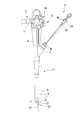
- FIG. 1is an overall view showing a suturing system 1 of the present embodiment.
- FIG. 2is a side view showing the needle holder 20 in the suturing system 1.
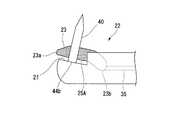
- FIG. 3is a side view showing the treatment portion 22 of the needle holder 20.
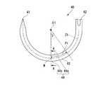
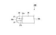
- FIG. 4is a side view of the curved needle 40 gripped by the needle holder 20.
- FIG. 5is a cross-sectional view taken along line AA in FIG.
- FIG. 6is a side view showing a state where the curved needle 40 is stably held by the needle holder 20.
- FIG. 7is a view showing a state in which the curved needle 40 is stably held by the needle holder 20 from the direction B in FIG. 6.
- the suturing system 1 of this embodimentincludes a flexible endoscope 2, a needle holder 20, and a curved needle 40.
- the flexible endoscope 2includes an insertion unit 3 and an operation unit 8.
- the insertion part 3has the imaging part 4, the active bending part 5, and the soft part 6 in this order from the front-end
- a treatment instrument channel 7 for inserting the needle holder 20 of the present embodimentis disposed inside the insertion portion 3.
- a distal end opening 7 a of the treatment instrument channel 7is disposed at the distal end of the insertion portion 3.
- the imaging unit 4can image a region to be treated.
- the imaging unit 4is disposed at the distal end portion of the insertion unit 3 such that the optical axis X1 extends in the longitudinal axis direction of the insertion unit 3.
- the imaging unit 4includes the first gripping member 23 and the second gripping member 26 in the needle holder 20 in a state where the needle holder 20 inserted through the treatment instrument channel 7 protrudes from the distal end opening 7a of the treatment instrument channel 7. (Described later) can be imaged.
- the active bending portion 5can actively bend in accordance with an operation performed on the operation portion 8 by the operator of the flexible endoscope 2.
- the operation unit 8is connected to the flexible unit 6.
- the operation unit 8is imaged by the grip 9 held by the operator, the input unit 10 that receives an operation for operating the active bending unit 5, the proximal end opening 7b of the treatment instrument channel 7, and the imaging unit 4.
- a universal code 11for outputting an image to the outside.
- the universal cord 11 provided in the operation unit 8can be connected to a display device (not shown) via an image processing device (not shown).
- the configuration of the flexible endoscope 2 in the present embodimentis not limited to the above configuration.
- a known flexible endoscope having one or more channelsmay be appropriately selected as a flexible endoscope that can be used with the needle holder 20.
- the channeldoes not have to be provided in the flexible endoscope itself.
- the needle holder 20includes a long flexible tube portion 21 having flexibility, a treatment portion 22 disposed at a distal end 21 a of the flexible tube portion 21, and a flexible tube portion 21. And an operation wire 35 disposed inside the flexible tube portion 21 and connected to the operation portion 31 and the treatment portion 22.
- the flexible tube portion 21can be inserted into the treatment instrument channel 7 of the flexible endoscope 2 shown in FIG. In a state where the flexible tube portion 21 is inserted into the treatment instrument channel 7, the distal end 21 a of the flexible tube portion 21 can project and retract from the distal end opening 7 a of the treatment instrument channel 7.
- the distal end 21 a of the flexible tube portion 21can enter the imaging field of the imaging unit 4 of the flexible endoscope 2 and is imaged by the imaging unit 4.
- the treatment section 22includes a first gripping member 23 and a second gripping member 26 for gripping the curved needle 40, and the first gripping member 23 is a second gripping member.
- a connecting portion 28 and a connecting shaft 29are provided for connecting the first gripping member 23 and the second gripping member 26 so as to be capable of opening and closing with respect to 26.
- the first gripping member 23is connected to the distal end 21 a of the flexible tube portion 21 via the connection portion 28 and the connecting shaft 29.
- a proximal end 23 b of the first gripping member 23is connected to a distal end 35 a of the operation wire 35.
- the first gripping member 23has a connecting hole 23c for connecting the first gripping member 23 to the connecting portion 28 via the connecting shaft 29 between the distal end 23a and the base end 23b of the first gripping member 23. is doing.
- the surface of the first gripping member 23 that faces the second gripping member 26has a first gripping surface 25 that can contact the curved needle 40.
- the first gripping surface 25is a surface that is substantially parallel to a second gripping surface 27 (described later) of the second gripping member 26 in a state where the curved needle 40 is gripped by the first gripping member 23 and the second gripping member 26. is there.
- the second gripping member 26is coupled to the distal end 21 a of the flexible tube portion 21 via the connection portion 28 so as to extend in the center line (center axis) Y1 direction of the flexible tube portion 21.
- the second gripping member 26 and the connection portion 28are integrally formed.
- the second gripping member 26has a second gripping surface 27 that is inclined with respect to the center line Y ⁇ b> 1 of the flexible tube portion 21 and is directed to the base end 26 b side of the second gripping member 26. That is, as shown in FIGS.
- the second grippingis performed with respect to a straight line parallel to the straight line Y ⁇ b> 3 that is an extension line of the center line Y ⁇ b> 1 of the flexible tube portion 21 in the side view in the extending direction of the connecting shaft 29.
- the surface 27(a straight line connecting the proximal end to the distal end of the second gripping surface 27) is inclined so as to have an acute angle on the proximal end side of the second gripping surface 27.
- a central region P1) including P2is located between the distal end 26a of the second gripping member 26 and the needle tip 41 of the curved needle 40 in the central axis direction of the flexible tube portion 21.
- the second gripping surface 27is arranged such that the distal end 27 a side of the second gripping surface 27 approaches the first gripping member 23 with respect to the center line Y1 of the flexible tube portion 21. It is inclined from the base end 27b side to the distal end 27a side.
- the second gripping surface 27may be inclined linearly when viewed from the long axis direction of the rotation axis Y2.
- the second gripping surface 27is 5 ° or more and 20 ° or less with respect to a straight line Y3 that is an extension line of the center line Y1 of the flexible tube portion 21 when viewed from the direction in which the rotation axis Y2 of the treatment portion 22 extends.
- a constant angle ⁇ 1 in the range of Unlike the unevenness for preventing slipping, the second gripping surface 27is provided as a flat surface for gripping the curved needle 40 in a predetermined range near the tip 26 a of the second gripping member 26.
- the connecting portion 28has a connecting hole portion 28a for connecting and fixing the connecting shaft 29.
- a center line Y2 of the connecting shaft 29 connected to the connecting portion 28extends in a direction orthogonal to a straight line Y3 that is an extension of the center line Y1 of the flexible tube portion 21. Since the first gripping member 23 and the second gripping member 26 are connected by the connecting hole portions 23c and 28a and the connecting shaft 29, the first gripping member 23 is orthogonal to the center line Y1 of the flexible tube portion 21.
- a straight line extending in the direction of rotationis defined as a rotation axis Y2 (center line Y2 of the connecting shaft 29), and can be rotated around the rotation axis Y2.
- the first gripping member 23can open and close with respect to the second gripping member 26. That is, in the treatment portion 22 in the present embodiment, the first gripping member 23 opens and closes with respect to the second gripping member 26 that is coupled to the distal end 21 a of the flexible tube portion 21 via the connection portion 28 and the coupling shaft 29. This is a single-open treatment section.
- the operation unit 31includes an operation unit main body 32, a slider 33, and a fixing mechanism (such as a ratchet mechanism) that restricts the slider 33 from moving toward the distal end side with respect to the operation unit main body 32. And a release button 34 for the fixing mechanism.
- the distal end 32 a of the operation portion main body 32is fixed to the proximal end 21 b of the flexible tube portion 21.
- the slider 33is connected to the operation unit main body 32 so as to be movable back and forth in the long axis direction of the operation unit main body. Further, the slider 33 is connected to the proximal end 35 b of the operation wire 35.
- the operation wire 35can be moved along the center line Y ⁇ b> 1 of the flexible tube portion 21 by moving the slider 33 forward and backward along the operation portion main body 32.
- the operation wire 35can be pulled toward the operation unit 31 by moving the slider 33 toward the proximal end side along the operation unit main body 32.
- the slider 33can restrict the movement toward the distal end side at a desired position by a fixing mechanism. For this reason, the slider 33 can be locked in a state where the slider 33 is pulling the operation wire 35, and the state where the operation wire 35 is pulled can be maintained.
- the operation wire 35transmits an operation force amount for performing an opening / closing operation of the first gripping member 23 with respect to the second gripping member 26 from the operation unit 31 to the first gripping member 23.
- a distal end 35 a of the operation wire 35is connected to a proximal end 23 b of the first gripping member 23.
- a base end 35 b of the operation wire 35is connected to the slider 33 of the operation unit 31.
- the operation wire 35is difficult to extend in the longitudinal direction of the operation wire 35 and can be deformed such that the longitudinal axis of the operation wire 35 is curved.
- the first holding member 23moves in the closing direction with respect to the second holding member 26.
- a gripping force amount of the curved needle 40 by the first gripping member 23 and the second gripping member 26is generated.
- the curved needle 40has an arc shape having a predetermined curvature.
- the curved needle 40includes a needle tip 41 that can be inserted into a tissue, a needle base portion 42 that is connected to a suture, and a needle tip 41 and a needle base portion 42 that connect the needle tip 41 and the needle base portion 42. Needle body 43 disposed between the two.
- the needle main body 43(curved needle 40) has at least a part of the outer periphery of the curved needle 40 in a cross section orthogonal to the center line Z ⁇ b> 1 extending along the arc of the curved needle 40.
- the flat portion 44is formed flat. Thereby, in a state where the curved needle 40 is gripped by the first gripping surface 25 and the second gripping surface 27, the flat portion 44 comes into contact with at least one of the first gripping surface 25 and the second gripping surface 27, thereby The posture of the curved needle 40 can be constrained so that the tip 41 is located proximal to the flat portion 44. More specifically, the flat part 44 is a first flat part 44a and a second flat part 44b.
- the first flat portion 44 ahas a cross section orthogonal to the center line Z ⁇ b> 1 extending along the arc of the curved needle 40, and the inner side of the curved needle 40 in the outer periphery of the needle main body 43 (the center of curvature O ⁇ b> 1 of the curved needle 40). Near the side).
- the second flat portion 44bhas a cross section orthogonal to the center line Z1 extending along the arc of the curved needle 40, and the outer side of the curved portion of the curved needle 40 in the outer periphery of the needle main body portion 43 (the center of curvature O1 of the curved needle 40). It is formed on the far side).
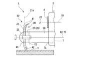
- FIG. 8is a view showing a state where the needle holder 20 is inserted through the flexible endoscope 2.
- the curved needle 40 introduced to the vicinity of the site to be suturedis grasped using the needle holder 20 under an endoscopic view.
- the operator of the needle holder 20positions the needle main body 43 of the curved needle 40 between the first gripping member 23 and the second gripping member 26.
- the curved needle 40is gripped using the operation unit 31.
- the operatorgently grasps the needle main body 43 of the curved needle 40 by gently pulling the slider 33 toward the proximal end side of the operation portion 31 and moving the first grasping member 23 toward the second grasping member 26.
- the needle tip 41is slightly on the proximal end side.
- the position of the curved needle 40is stabilized in the inclined state.
- the movement of the slider 33 toward the distal endis restricted by the fixing mechanism. Accordingly, the curved needle 40 is maintained in a state of being gripped by the first gripping member 23 and the second gripping member 26 so that the curved needle 40 does not rotate.
- the curved needle 40is connected to the first gripping member 23 and the second gripping member so that the second flat portion 44b is in contact with the first gripping surface 25 and the first flat portion 44a is in contact with the second gripping surface 27. It can also be gripped by 26.
- a preferable gripping state of the curved needle 40 in the present embodimentis a state in which the first flat portion 44 a is in contact with the first gripping surface 25 and the second flat portion 44 b is in contact with the second gripping surface 27.
- the slider 33In a state where the curved needle 40 is gripped by the needle holder 20 so that the first flat portion 44a is in contact with the first gripping member 23 and the second flat portion 44b is in contact with the second gripping member 26, the slider 33 is on the distal end side.
- the second gripping member 26restrains the posture of the curved needle 40 so that the needle tip 41 is located on the proximal end side with respect to the second flat portion 44b.
- the center line X2 of the distal end opening 7a of the treatment instrument channel 7 of the flexible endoscope 2is separated from the optical axis X1 so as to be substantially parallel to the optical axis X1 of the imaging unit 4. For this reason, the distal end portion of the needle holder 20 protruding from the distal end opening 7a of the treatment instrument channel 7 protrudes toward the distal end side substantially parallel to the optical axis X1.
- the center line Z1a of the curved needle 40is positioned in a plane orthogonal to the straight line Y3 that is an extension of the center line Y1 of the flexible tube portion 21.
- the treatmentis often performed while the tissue to be sutured is captured below the endoscope image.
- the needle tip 41 of the curved needle 40moves from the position close to the optical axis X1 (see FIG. 8) in the direction away from the optical axis X1 toward the tissue T.
- the center line Z1a of the curved needle 40is located in a plane orthogonal to the straight line Y3 that is an extension of the center line Y1 as shown by a two-dot chain line in FIG. Then, it seems that the needle tip 41 moves further to the far side than actual.
- the curved needle 40is held by the needle holder 20 so that the center line Z1 of the curved needle 40 is positioned in a plane orthogonal to the straight line Y3. Then, by misrecognizing the position of the needle tip 41 in the optical axis X1 direction of the imaging unit 4, there is a possibility that the needle tip 41 may be inserted into the tissue deeper than intended by the operator of the needle holder 20. is there.
- the curved needle 40is held by the needle holder 20 so that the central line Z1a of the curved needle 40 is positioned in a plane orthogonal to the straight line Y3 that is an extension of the central line Y1 of the flexible tube portion 21.
- the suturing system 1since the suturing system 1 includes the curved needle 40 having the first flat portion 44a and the second flat portion 44b, the second flat portion 44b comes into contact with the second gripping surface 27 and the curved needle. In addition to restraining the posture of 40, the posture of the curved needle 40 can also be restrained by the first flat portion 44a coming into contact with the first gripping surface 25. For this reason, according to the suturing system 1 of the present embodiment, the curved needle 40 can be gripped more stably as compared with the case where only the second flat portion 44 b is formed on the curved needle 40. In addition, the suture set including the needle holder 20 of the present embodiment and the curved needle 40 having the first flat portion 44a and the second flat portion 44b is used in appropriate combination with a known flexible endoscope. The above effects are achieved.
- FIG. 9is a side view showing a treatment portion in the needle holder of the present modification.
- the first gripping member 23 in this modificationhas a first gripping surface 25 ⁇ / b> A having a configuration different from that of the first gripping surface 25 disclosed in the first embodiment.
- the first gripping surface 25A in this modificationis curved in the vicinity of the distal end 23a so as to gradually approach the second gripping member 26 side from the proximal end 23b of the first gripping member 23 toward the distal end 23a.
- the first gripping surface 25A of the present modified examplemoves the curved needle 40 toward the distal end side of the treatment portion 22 by the gripping force in a state where the curved needle 40 is gripped by the first gripping member 23 and the second gripping member 26.
- the curved needle 40can be reliably gripped by the first gripping member 23 and the second gripping member 26.
- FIG. 10is a side view showing a treatment portion in the needle holder of the present modification.
- FIG. 11is a view showing a treatment portion in the needle holder of the present modified example from the direction C of FIG.
- the second gripping member 26 in this modificationhas a protrusion 39 that protrudes from the tip 27 a of the second gripping surface 27 toward the first gripping surface 25.
- the protruding portion 39moves to the distal end side of the treatment portion 22, and the first gripping member 23 and the second gripping member 39
- the curved needle 40can be supported so that the curved needle 40 does not fall out from between the gripping member 26 and the gripping member 26.
- the protrusion 39 in this modificationhas a recess 39a into which the tip 23a of the first gripping member 23 enters. Since the depression 39 a is provided in the protrusion 39, the curved needle 40 having a diameter smaller than the distance from the second holding surface 27 to the protruding end of the protrusion 39 is formed by the first holding member 23 and the second holding member 26. It can be gripped.
- FIG. 12is a side view showing a state in which the needle holder of the present modification is inserted through the flexible endoscope.
- FIG. 13is a view for explaining the operation of grasping and suturing the curved needle using the needle holder of the present modification.
- the suturing system 1includes a needle holder 20 ⁇ / b> A that is optimized for the configuration of the treatment instrument channel 7 and the imaging unit 4 of the flexible endoscope 2.
- the second gripping surface 27 ⁇ / b> A formed on the second gripping member 26is located in the central region P ⁇ b> 1 of the needle main body 43 of the curved needle 40 between the first gripping member 23 and the second gripping member 26.
- the posture of the curved needle 40is constrained so that the distance L2 is equal to each other.
- the central region P1is, for example, a predetermined angle from an intermediate point M between the needle tip 41 and the needle base portion 42 on the center line Z1 of the curved needle 40 toward the needle base portion 42 with the center of curvature O of the curved needle 40 as the center. It is an area including a range up to ⁇ .
- the predetermined angle ⁇is 30 °.
- the second gripping surface 27Ais constant with respect to a straight line Y3 that is an extension of the center line Y1 of the flexible tube portion 21 when viewed from the direction in which the rotation axis Y2 of the treatment portion 22 extends.
- An angle ⁇ 2is formed.
- the constant angle ⁇ 2is set corresponding to the configuration of the treatment instrument channel 7 and the imaging unit 4 of the flexible endoscope 2.
- the second gripping surface 27Ahas a constant angle ⁇ 2 optimized for the configuration of the flexible endoscope 2 used with the needle holder 20 of the present modification.
- the variation in the distance of the needle tip 41 on the image picked up by the image pickup portion 4is further reduced.
- the misperception of the perspective of the needle tip 41 in the process of inserting the needle tip 41 into the tissueis less likely to occur.
- FIG. 14is a plan view showing a second gripping surface of the needle holder of the present embodiment.
- FIG. 15is a front view showing the treatment section.
- the needle holder 20 ⁇ / b> B according to the present embodimentis different from the second gripping member 26 in the configuration in place of the second gripping member 26 disclosed in the first embodiment.
- Two gripping members 36are provided.
- the 2nd holding member 36 of this embodimenthas the 2nd holding surface 37 which contact
- the second gripping member 36has a groove portion 38 that extends from the distal end 36 a of the second gripping member 36 toward the base end 36 b of the second gripping member 36.
- the second gripping surface 37is divided into two by a groove 38.
- the second gripping surface 37has boundary portions 37 a and 37 b with the groove portion 38.
- the boundary portions 37a and 37bare groove edges extending in the longitudinal axis direction of the groove portion 38 at a position where the second gripping surface 37 and the groove portion 38 intersect, and the edges may be corner portions.
- a round shapemay be applied instead of a shape with a chamfered corner or a corner.
- the groove portion 38extends linearly from the distal end 36 a of the second gripping member 36 toward the base end 36 b of the second gripping member 36.
- the first gripping member 23becomes the first of the curved needle 40. It contacts the flat portion 44a.
- the first flat portion 44a of the curved needle 40is sandwiched between the two positions (A1, A2) when viewed from the distal end 36a of the second gripping member 36 toward the proximal end 36b of the second gripping member 36.
- the second flat portion 44b formed outside the curved needle 40 on the outer periphery of the curved needle 40is supported by the boundary portions 37a and 37b at two locations (A1, A2) that are separated from each other.
- the posture of the curved needle 40 when the curved needle 40 is gripped by the first gripping member 23 and the second gripping member 36can be made more stable than in the first embodiment.
- the concrete structureis not restricted to this embodiment, The design change etc. of the range which does not deviate from the summary of this invention are included.
- the needle holder 20 disclosed in the above embodimentsmay be used together with an endoscope different from the flexible endoscope 2 described above.
- the needle holder 20 of each of the above embodimentsmay be used with a side-view type endoscope.
- the operation part of the needle holder 20 disclosed in each of the above embodimentsmay be a curl linen type as shown in FIG. For example, as illustrated in FIG.
- the operation unit 51includes a pair of handles (a fixed handle 52 and a movable handle 53) that can be opened and closed, and a fixing mechanism (not shown) that fixes the movable handle 53. .
- the movable handle 53is connected to the fixed handle 52 so as to be rotatable about a predetermined opening / closing axis 53a with respect to the fixed handle 52. Further, the movable handle 53 is connected to the proximal end 35 b of the operation wire 35. By opening and closing the movable handle 53 with respect to the fixed handle 52, the operation wire 35 can be moved along the center line Y1 of the flexible tube portion 21.
- the base end portion 23b of the first gripping member 23 of the needle holder 20 disclosed in each of the above embodimentsis connected to the distal end 35a of the operation wire 35 via a connecting link 61 as shown in FIG. May be.
- the 1st holding membermay contact
- the effects disclosed in the above embodimentsare similarly achieved even when a known curved needle and endoscope are used in combination with the needle holder 20 of the above embodiments.
- the second gripping member 26 disclosed in the first embodimentmay have both the groove 38 and the protrusion 39.
- the present inventioncan be used for a medical instrument for suturing a tissue under a flexible endoscope.
Landscapes
- Health & Medical Sciences (AREA)
- Life Sciences & Earth Sciences (AREA)
- Surgery (AREA)
- General Health & Medical Sciences (AREA)
- Veterinary Medicine (AREA)
- Biomedical Technology (AREA)
- Heart & Thoracic Surgery (AREA)
- Medical Informatics (AREA)
- Molecular Biology (AREA)
- Animal Behavior & Ethology (AREA)
- Nuclear Medicine, Radiotherapy & Molecular Imaging (AREA)
- Public Health (AREA)
- Engineering & Computer Science (AREA)
- Physics & Mathematics (AREA)
- Biophysics (AREA)
- Optics & Photonics (AREA)
- Pathology (AREA)
- Radiology & Medical Imaging (AREA)
- Surgical Instruments (AREA)
- Endoscopes (AREA)
Abstract
Description
Translated fromJapanese本発明は、内視鏡用持針器、縫合セット、ならびに縫合システムに関する。The present invention relates to an endoscope needle holder, a suture set, and a suture system.
従来、体内の組織を縫合するために利用される持針器が知られている(例えば特許文献1参照)。また、腹腔鏡を用いた手術において腹腔鏡視下で体内の組織を縫合するための縫合器具が知られている(例えば特許文献2,3参照)。
また、軟性内視鏡の処置具チャンネルに挿通可能な可撓性を有する挿入部を備えた持針器が知られている(例えば特許文献4参照)。2. Description of the Related Art Conventionally, a needle holder used for suturing a body tissue is known (see, for example, Patent Document 1). In addition, a suturing instrument for suturing tissue in the body under laparoscopic surgery in a surgery using a laparoscope is known (see, for example,
Also, a needle holder having a flexible insertion portion that can be inserted into a treatment instrument channel of a flexible endoscope is known (see, for example, Patent Document 4).
軟性内視鏡の処置具チャンネルに挿入されて使用される持針器は、曲針を把持する一対のジョーを内視鏡の遠位端から突出および回転させることによって、内視鏡視下で曲針を移動させることができる。
一般的に、内視鏡の撮像部の光学特性として、光軸から離れた領域では対象物との相対距離が判断しにくい。内視鏡視下において曲針が持針器に把持されている場合には、内視鏡の光軸と曲針の針先との距離は、内視鏡の光軸と曲針の被把持部位との距離と異なっている。このため、曲針がこの持針器によって把持されている状態における針先と撮像部との距離が内視鏡視下でわかりにくくなってしまう場合がある。
本発明は、把持された曲針の針先と撮像部との距離が内視鏡視下でわかりやすくなる持針器を提供することを目的とする。A needle holder that is used by being inserted into a treatment instrument channel of a flexible endoscope projects and rotates a pair of jaws that grip a curved needle from the distal end of the endoscope under an endoscope. The curved needle can be moved.
Generally, as an optical characteristic of an imaging unit of an endoscope, it is difficult to determine a relative distance from an object in a region away from the optical axis. When the curved needle is gripped by the needle holder under the endoscope, the distance between the optical axis of the endoscope and the tip of the curved needle is determined by the grip of the optical axis of the endoscope and the curved needle. It is different from the distance to the part. For this reason, the distance between the needle tip and the imaging unit in a state in which the curved needle is held by the needle holder may be difficult to understand under endoscopic vision.
An object of the present invention is to provide a needle holder that makes it easy to understand the distance between the needle tip of a held curved needle and an imaging unit under an endoscopic view.
本発明の一態様は、軟性内視鏡の処置具チャンネルに挿通可能な可撓性を有する長尺の可撓管部と、前記可撓管部の先端部に回動可能に連結された第一把持部材と、前記可撓管部の先端部に設けられた第二把持部材と、を備え、前記第一把持部材の第一把持面と前記第二把持部材の第二把持面により曲針を把持した状態において、前記第一把持面と前記第二把持面により把持される前記曲針の被把持領域が、前記可撓管部の中心軸方向において、前記第二把持部材の先端と前記曲針の針先との間に位置するように、前記第二把持面が傾斜している持針器である。One aspect of the present invention is a flexible long flexible tube portion that can be inserted into a treatment instrument channel of a flexible endoscope, and a first flexible tube portion rotatably connected to a distal end portion of the flexible tube portion. One gripping member and a second gripping member provided at the tip of the flexible tube portion, and the curved needle is formed by the first gripping surface of the first gripping member and the second gripping surface of the second gripping member. In the state of gripping the gripping region of the curved needle gripped by the first gripping surface and the second gripping surface, the distal end of the second gripping member and the tip in the central axis direction of the flexible tube portion In the needle holder, the second gripping surface is inclined so as to be positioned between the needle tip of the curved needle.
前記第二把持面は、前記中心軸に対して5°以上20°以下の範囲で傾斜していることがより好ましい。More preferably, the second gripping surface is inclined in a range of 5 ° to 20 ° with respect to the central axis.
前記第二把持部材は、前記第二把持面の先端から前記第一把持部材側へ突出する突起部を有していてもよい。The second gripping member may have a protrusion protruding from the tip of the second gripping surface toward the first gripping member.
前記第二把持部材は、前記第二把持面の先端から基端へ向かって延びる溝部を有していてもよく、前記溝部は前記中心軸に対して直交する方向において前記第一把持面よりも幅が広くてもよい。The second gripping member may have a groove extending from the distal end to the base end of the second gripping surface, and the groove is more than the first gripping surface in a direction orthogonal to the central axis. The width may be wide.
本発明の第二の態様は、上記態様の持針器と、前記持針器により把持される曲針と、を備えた縫合セットであって、前記曲針は、前記曲針の弧に沿って延びる中心線に対して直交する断面において前記曲針の外周の少なくとも一部が平坦に形成された平坦部と、を有し、前記第一把持部材の第一把持面と前記第二把持部材の第二把持面により前記曲針を把持した状態において、前記平坦部は、前記第一把持部材の第一把持面と前記第二把持部材の第二把持面の少なくとも一方に当接することにより、前記針先が前記平坦部よりも近位側に位置するように前記曲針の姿勢を拘束する縫合セットである。A second aspect of the present invention is a suture set including the needle holder of the above aspect and a curved needle gripped by the needle holder, wherein the curved needle is along an arc of the curved needle. A flat portion in which at least a part of the outer periphery of the curved needle is formed flat in a cross section orthogonal to the center line extending in the direction, and the first gripping surface of the first gripping member and the second gripping member In the state where the curved needle is gripped by the second gripping surface, the flat portion comes into contact with at least one of the first gripping surface of the first gripping member and the second gripping surface of the second gripping member, It is a suture set which restrains the posture of the curved needle so that the needle tip is located on the proximal side of the flat portion.
本発明の第三の態様は、上記態様の持針器と、前記可撓管部が挿入される処置具チャンネルを有するとともに前記処置具チャンネルの先端から突出する前記持針器のうち少なくとも前記第一把持部材及び前記第二把持部材を撮像可能な撮像部を有する内視鏡と、を備えた縫合システムであって、前記把持面は、前記第一把持部材と前記第二把持部材との間に曲針が把持された状態において、前記撮像部から前記曲針の中央部までの第一直線距離と前記撮像部から前記曲針の針先部までの第二直線距離とが互いに等しくなるように前記曲針の姿勢を拘束可能となる角度を有して傾斜している縫合システムである。According to a third aspect of the present invention, there is provided at least the first of the needle holders of the above aspect and the needle holders having a treatment instrument channel into which the flexible tube portion is inserted and projecting from a distal end of the treatment instrument channel. An endoscope having an imaging unit capable of imaging one gripping member and the second gripping member, wherein the gripping surface is between the first gripping member and the second gripping member The first linear distance from the imaging unit to the center of the curved needle and the second linear distance from the imaging unit to the needle tip of the curved needle are equal to each other when the curved needle is held A suturing system that is inclined at an angle that allows the posture of the curved needle to be restrained.
本発明によれば、把持された曲針の針先と撮像部との距離が内視鏡視下でわかりやすい。According to the present invention, the distance between the needle tip of the held curved needle and the imaging unit is easy to understand under endoscopic vision.
(第1実施形態)
本発明の一実施形態について説明する。図1は、本実施形態の縫合システム1を示す全体図である。図2は、縫合システム1における持針器20を示す側面図である。図3は、持針器20の処置部22を示す側面図である。図4は、持針器20により把持される曲針40の側面図である。図5は、図4のA-A線における断面図である。図6は、持針器20によって曲針40が安定して把持された状態を示す側面図である。図7は、持針器20によって曲針40が安定して把持された状態を図6のB方向から示す図である。(First embodiment)
An embodiment of the present invention will be described. FIG. 1 is an overall view showing a
図1から図4までに示すように、本実施形態の縫合システム1は、軟性内視鏡2と、持針器20と、曲針40とを備えている。As shown in FIGS. 1 to 4, the
軟性内視鏡2は、挿入部3と、操作部8とを備えている。
挿入部3は、先端から、撮像部4、能動湾曲部5、及び軟性部6をこの順に有している。また、挿入部3の内部には、本実施形態の持針器20を挿通するための処置具チャンネル7が配されている。挿入部3の先端には、処置具チャンネル7の先端開口部7aが配されている。The
The
撮像部4は、処置対象となる部位を撮像可能である。撮像部4は、挿入部3の長手軸方向に光軸X1が延びるように挿入部3の先端部分に配されている。撮像部4は、処置具チャンネル7に挿通された持針器20が処置具チャンネル7の先端開口部7aから突出している状態において、持針器20における第一把持部材23及び第二把持部材26(後述)を撮像することができる。
能動湾曲部5は、軟性内視鏡2の操作者が操作部8に対して行う操作に従って能動的に湾曲動作可能である。The
The
操作部8は、軟性部6に接続されている。操作部8は、操作者によって把持されるグリップ9と、能動湾曲部5を動作させるための操作を受け付ける入力部10と、処置具チャンネル7の基端開口部7bと、撮像部4が撮像した画像を外部へ出力するためのユニバーサルコード11とを有する。操作部8に設けられたユニバーサルコード11は、画像処理装置(不図示)を介して表示装置(不図示)に接続可能である。The
本実施形態における軟性内視鏡2の構成は、上記の構成に限定されない。たとえば、持針器20とともに使用可能な軟性内視鏡として、1つ以上のチャンネルを有する公知の軟性内視鏡が適宜選択されてよい。また、本実施形態の持針器20を挿入することができるチャンネルを外付けチャンネルとして取り付け可能な軟性内視鏡であれば、軟性内視鏡自体にチャンネルが設けられていなくてもよい。The configuration of the
図2に示すように、持針器20は、可撓性を有する長尺の可撓管部21と、可撓管部21の先端21aに配された処置部22と、可撓管部21の基端21bに配された操作部31と、可撓管部21の内部に配され操作部31及び処置部22に接続された操作ワイヤ35と、を備えている。As shown in FIG. 2, the
可撓管部21は、図1に示す軟性内視鏡2の処置具チャンネル7に挿通可能である。可撓管部21が処置具チャンネル7に挿通された状態において、可撓管部21の先端21aは、処置具チャンネル7の先端開口部7aから突没可能である。可撓管部21の先端21aは、軟性内視鏡2の撮像部4の撮像視野内に進入可能であり、撮像部4に撮像される。The
図2,図3,及び図6に示すように、処置部22は、曲針40を把持するための第一把持部材23及び第二把持部材26と、第一把持部材23が第二把持部材26に対して開閉動作可能となるように第一把持部材23と第二把持部材26とを連結する接続部28および連結軸29とを備えている。As shown in FIGS. 2, 3, and 6, the
第一把持部材23は、接続部28および連結軸29を介して可撓管部21の先端21aに連結されている。第一把持部材23の基端23bは、操作ワイヤ35の先端35aに接続されている。第一把持部材23は、連結軸29を介して第一把持部材23を接続部28に連結するための連結孔部23cを、第一把持部材23の先端23aと基端23bとの間に有している。第一把持部材23において第二把持部材26に向けられた面は、曲針40に接触可能な第一把持面25を有している。第一把持面25は、第一把持部材23と第二把持部材26とによって曲針40が把持された状態で第二把持部材26の第二把持面27(後述)と略平行となる面である。The first gripping
第二把持部材26は、可撓管部21の中心線(中心軸)Y1方向に延びるように、接続部28を介して可撓管部21の先端21aに連結されている。本実施形態では、第二把持部材26と接続部28とは一体成型されている。第二把持部材26は、可撓管部21の中心線Y1に対して傾斜して第二把持部材26の基端26b側に向けられた第二把持面27を有している。すなわち、図3、図6に示すように、連結軸29の延びる方向における側視において、可撓管部21の中心線Y1の延長線となる直線Y3と平行な直線に対して、第二把持面27(第二把持面27の近位端から遠位端とを結ぶ直線)が、第二把持面27の近位端側で鋭角になるように傾斜している。第一把持面25と第二把持面27により曲針40が把持された状態において、第一把持面25と第二把持面27により把持される曲針40の被把持領域(後述する被把持部P2を含む中央領域P1)が、可撓管部21の中心軸方向において、第二把持部材26の先端26aと曲針40の針先41との間に位置する。
具体的には、第二把持面27は、可撓管部21の中心線Y1に対して第二把持面27の遠位端27a側が第一把持部材23に近づくように、第二把持面27の基端27b側から遠位端27a側にむかって傾斜している。例えば、回動軸Y2の長軸方向から見たときに第二把持面27は直線的に傾斜していても良い。
第二把持面27は、処置部22における回動軸Y2が延びる方向から見たときに、可撓管部21の中心線Y1の延長線となる直線Y3に対して、5°以上20°以下の範囲の一定角度θ1をなしている。第二把持面27は、滑り止めのための凹凸とは異なり、曲針40を把持するための平面として、第二把持部材26の先端26a近傍の所定の範囲に設けられている。The second gripping
Specifically, the second
The second
接続部28は、連結軸29を連結固定するための連結孔部28aを有している。接続部28に連結された連結軸29の中心線Y2は、可撓管部21の中心線Y1の延長線となる直線Y3に対して直交する方向に延びる。第一把持部材23と第二把持部材26とが連結孔部23c、28aおよび連結軸29によって連結されているので、第一把持部材23は、可撓管部21の中心線Y1に対して直交する方向に延びる直線を回動軸Y2(連結軸29の中心線Y2)として、この回動軸Y2回りに回動可能である。これにより、第一把持部材23は、第二把持部材26に対して開閉動作することができる。すなわち、本実施形態における処置部22は、可撓管部21の先端21aに接続部28と連結軸29を介して連結された第二把持部材26に対して第一把持部材23が開閉動作する片開きの処置部である。The connecting
図2に示すように、操作部31は、操作部本体32と、スライダ33と、スライダ33が操作部本体32に対して遠位端側へ移動するのを制限する固定機構(ラチェット機構等、不図示)と、固定機構の解除ボタン34とを有している。
操作部本体32の先端32aは、可撓管部21の基端21bに固定されている。スライダ33は、操作部本体32に対して操作部本体の長軸方向に進退可能に連結されている。さらに、スライダ33は、操作ワイヤ35の基端35bに連結されている。操作部本体32に沿ってスライダ33を進退動作させることによって、操作ワイヤ35を可撓管部21の中心線Y1に沿って移動させることができる。本実施形態では、スライダ33を操作部本体32に沿って基端側へ移動させることによって、操作ワイヤ35を操作部31側へと牽引することができる。スライダ33は、固定機構により所望の位置で遠位端側への移動を規制可能である。このため、スライダ33が操作ワイヤ35を牽引している状態でスライダ33をロックして、操作ワイヤ35が牽引された状態を維持できる。As shown in FIG. 2, the operation unit 31 includes an operation unit
The
図2及び図3に示すように、操作ワイヤ35は、第二把持部材26に対する第一把持部材23の開閉動作を行なうための操作力量を操作部31から第一把持部材23へと伝達するための柔軟なワイヤである。操作ワイヤ35の先端35aは、第一把持部材23の基端23bに接続されている。操作ワイヤ35の基端35bは、操作部31のスライダ33に接続されている。
操作ワイヤ35は、操作ワイヤ35の長手方向へは伸長しにくく、操作ワイヤ35の長手軸線が湾曲するような変形が可能である。操作ワイヤ35が操作部31側へ牽引されることによって、第二把持部材26に対して第一把持部材23が閉じる方向へ移動する。操作ワイヤ35が操作部31側へ牽引されることによって、第一把持部材23と第二把持部材26とによる曲針40の把持力量が生じる。As shown in FIGS. 2 and 3, the
The
図4から図7までに示すように、曲針40は、所定の曲率を有する弧状をなしている。曲針40は、組織に刺入可能な針先41と、縫合糸と連結される針元部42と、針先41と針元部42とを繋ぐように針先41と針元部42との間に配された針本体部43とを有している。4 to 7, the
図4及び図5に示すように、針本体部43(曲針40)は、曲針40の弧に沿って延びる中心線Z1に対して直交する断面において曲針40の外周の少なくとも一部が平坦に形成された平坦部44を有している。
これにより、第一把持面25と第二把持面27により曲針40を把持した状態において、平坦部44は、第一把持面25と第二把持面27の少なくとも一方に当接することにより、針先41が平坦部44よりも近位側に位置するように曲針40の姿勢を拘束することができる。
平坦部44は、より具体的には、第一平坦部44aと、第二平坦部44bである。
第一平坦部44aは、曲針40の弧に沿って延びる中心線Z1に対して直交する断面において、針本体部43の外周のうち曲針40の湾曲における内側(曲針40の曲率中心O1に近い側)に形成されている。
第二平坦部44bは、曲針40の弧に沿って延びる中心線Z1に対して直交する断面において、針本体部43の外周のうち曲針40の湾曲における外側(曲針40の曲率中心O1から遠い側)に形成されている。As shown in FIGS. 4 and 5, the needle main body 43 (curved needle 40) has at least a part of the outer periphery of the
Thereby, in a state where the
More specifically, the
The first
The second
本実施形態の縫合システム1の作用について説明する。図8は、持針器20が軟性内視鏡2に挿通された状態を示す図である。
本実施形態の縫合システム1を用いて体内の組織を縫合する場合には、縫合対象部位近傍まで導入された曲針40を、内視鏡視下で持針器20を用いて把持する。The operation of the
When the tissue in the body is sutured using the
縫合に適した姿勢で曲針40を把持するために、持針器20の操作者は、曲針40の針本体部43が第一把持部材23と第二把持部材26との間に位置するように、操作部31を用いて曲針40を把持する。たとえば、操作者は、スライダ33を操作部31の基端側へ軽く牽引して第一把持部材23を第二把持部材26側へと移動させることで曲針40の針本体部43を軽く把持する。図6及び図7に示すように第一平坦部44aが第一把持面25に接し、第二平坦部44bが第二把持面27に接した状態になると、針先41がやや基端側に傾斜した状態で曲針40の位置が安定する。この状態で操作者がスライダ33をさらに牽引すると、スライダ33の遠位端側への移動が固定機構で制限される。これにより、曲針40が回転しないように、第一把持部材23と第二把持部材26とによって曲針40を把持した状態で維持される。In order to grip the
なお、本実施形態では、第二平坦部44bが第一把持面25に接し、第一平坦部44aが第二把持面27に接するように曲針40を第一把持部材23及び第二把持部材26によって把持することもできる。しかしながら、本実施形態における曲針40の好ましい把持状態は、第一平坦部44aが第一把持面25に接し、第二平坦部44bが第二把持面27に接した状態である。In the present embodiment, the
第一平坦部44aが第一把持部材23に接し第二平坦部44bが第二把持部材26に接するように曲針40が持針器20に把持された状態において、スライダ33が遠位端側へ移動しないようにスライダ33の移動が規制されると、第二把持部材26は、針先41が第二平坦部44bよりも基端側に位置するように曲針40の姿勢を拘束する。In a state where the
本実施形態において、軟性内視鏡2の処置具チャンネル7の先端開口部7aの中心線X2は、撮像部4の光軸X1と略平行となるように光軸X1から離間している。このため、処置具チャンネル7の先端開口部7aから突出した持針器20の先端部分は、光軸X1と略平行に先端側へ突出している。この状態で、図8に二点鎖線で示すように可撓管部21の中心線Y1の延長線となる直線Y3に対して直交する面内に曲針40の中心線Z1aが位置するように曲針40が持針器20に把持されると、軟性内視鏡2の撮像部4によって撮像された画像において、曲針40の針本体部43までの距離と曲針40の針先41までの距離とが極端に異なって見える場合がある。In this embodiment, the center line X2 of the distal end opening 7a of the
軟性内視鏡2に持針器20を挿通して縫合をする場合には、内視鏡画像の下側に縫合対象組織を捉えながら処置をすることが多いので、縫合における組織への穿刺過程で、曲針40の針先41は、光軸X1に近い位置(図8参照)から、光軸X1から離れて組織Tへ向かう方向へと移動する。このとき、図8に二点鎖線で示すように中心線Y1の延長線となる直線Y3に対して直交する面内に曲針40の中心線Z1aが位置していると、内視鏡画像上では実際よりもさらに遠方側へ針先41が移動するように見える。このため、上記の直線Y3に対して直交する面内に曲針40の中心線Z1が位置するように曲針40が持針器20に把持された状態で内視鏡視下で縫合をしようとすると、撮像部4の光軸X1方向における針先41の位置を誤認することで、持針器20の操作者が意図するよりも深く針先41を組織に刺入させてしまう可能性がある。
また、可撓管部21の中心線Y1の延長線となる直線Y3に対して直交する面内に曲針40の中心線Z1aが位置するように曲針40が持針器20に把持された状態で内視鏡視下で縫合をしようとすると、針先41が組織に対して進入する角度が意図する角度よりも深くなり、針先41の刺入抵抗が意図した大きさよりも小さくなって必要以上に深く組織を穿刺してしまう可能性がある。When the
In addition, the
これに対して、本実施形態では、図6に示すように、第二平坦部44bよりも針先41が基端側に向けられているので、軟性内視鏡2の撮像部4によって撮像された画像上において、針先41と針本体部43とが略等距離に見える。これにより、本実施形態の持針器20によって把持された曲針40の針先41と撮像部4との距離がわかりやすくなっている。その結果、本実施形態の縫合システム1によれば、組織に対して意図する以上に深く曲針40を刺入してしまう可能性を減少させることができる。On the other hand, in this embodiment, as shown in FIG. 6, since the
また、本実施形態では、第一平坦部44a及び第二平坦部44bを有する曲針40を縫合システム1が備えていることによって、第二平坦部44bが第二把持面27に接して曲針40の姿勢が拘束されることに加えて、第一平坦部44aが第一把持面25に接することでも曲針40の姿勢を拘束可能である。このため、本実施形態の縫合システム1によれば、第二平坦部44bのみが曲針40に形成されている場合と比較して、曲針40をさらに安定して把持可能である。
また、本実施形態の持針器20と上記の第一平坦部44a及び第二平坦部44bを有する曲針40とを備えた縫合セットは、公知の軟性内視鏡と適宜組み合わせて使用されることで上記の効果を奏する。In the present embodiment, since the
In addition, the suture set including the
(変形例1)
上記第1実施形態の変形例について説明する。図9は、本変形例の持針器における処置部を示す側面図である。
図9に示すように、本変形例における第一把持部材23は、上記第1実施形態に開示された第一把持面25とは構成が異なる第一把持面25Aを有している。
本変形例における第一把持面25Aは、先端23a近傍において、第一把持部材23の基端23bから先端23a側へ行くに従って漸次第二把持部材26側に近づくように湾曲している。本変形例の第一把持面25Aは、第一把持部材23と第二把持部材26とによって曲針40が把持された状態において、把持力により曲針40が処置部22の先端側に移動するのを制限する。これにより、本変形例では、操作ワイヤ35の牽引力が強くても第一把持部材23と第二把持部材26とによって確実に曲針40を把持することができる。(Modification 1)
A modification of the first embodiment will be described. FIG. 9 is a side view showing a treatment portion in the needle holder of the present modification.
As shown in FIG. 9, the first gripping
The first
(変形例2)
上記第1実施形態の他の変形例について説明する。図10は、本変形例の持針器における処置部を示す側面図である。図11は、本変形例の持針器における処置部を図10のC方向から示す図である。(Modification 2)
Another modification of the first embodiment will be described. FIG. 10 is a side view showing a treatment portion in the needle holder of the present modification. FIG. 11 is a view showing a treatment portion in the needle holder of the present modified example from the direction C of FIG.
図10及び図11に示すように、本変形例における第二把持部材26は、第二把持面27の先端27aから第一把持面25側へ突出する突起部39を有している。As shown in FIGS. 10 and 11, the second gripping
突起部39は、第一把持部材23と第二把持部材26とによって曲針40が把持された状態において、処置部22の先端側に曲針40が移動して第一把持部材23と第二把持部材26との間から曲針40が抜け落ちてしまうことがないように、曲針40を支持することができる。In the state in which the
また、本変形例における突起部39は、第一把持部材23の先端23aが入り込む窪み39aを有していている。窪み39aが突起部39に設けられていることにより、第二把持面27から突起部39の突出端までの距離よりも直径が小さな曲針40を第一把持部材23及び第二把持部材26によって把持することができる。Further, the
(変形例3)
上記第1実施形態のさらに他の変形例について説明する。図12は、本変形例の持針器が軟性内視鏡に挿通された状態を示す側面図である。図13は、本変形例の持針器を用いて曲針を把持して縫合をする動作を説明するための図である。(Modification 3)
Still another modification of the first embodiment will be described. FIG. 12 is a side view showing a state in which the needle holder of the present modification is inserted through the flexible endoscope. FIG. 13 is a view for explaining the operation of grasping and suturing the curved needle using the needle holder of the present modification.
図12及び図13に示すように、本変形例における縫合システム1は、軟性内視鏡2の処置具チャンネル7及び撮像部4の構成に対応して最適化された持針器20Aを備えている。
本変形例において、第二把持部材26に形成された第二把持面27Aは、第一把持部材23と第二把持部材26との間に曲針40の針本体部43の中央領域P1のなかの任意の被把持部P2が把持された状態において、撮像部4から曲針40の被把持部P2までの第一直線距離L1と、撮像部4から曲針40の針先41までの第二直線距離L2とが互いに等しくなるように、曲針40の姿勢を拘束する。中央領域P1は、たとえば、曲針40の中心線Z1上における針先41と針元部42との中間点Mから、曲針40の曲率中心Oを中心として針元部42側へ所定の角度γまでの範囲を含んだ領域である。たとえば所定の角度γは30°である。As shown in FIGS. 12 and 13, the
In this modification, the second
本変形例において、第二把持面27Aは、処置部22における回動軸Y2が延びる方向から見たときに、可撓管部21の中心線Y1の延長線となる直線Y3に対して、一定角度θ2をなしている。上記の一定角度θ2は、軟性内視鏡2の処置具チャンネル7及び撮像部4の構成に対応して設定される。In the present modification, the second
本変形例では、第二把持面27Aが、本変形例の持針器20と共に使用される軟性内視鏡2の構成に最適化された一定角度θ2を有しているので、可撓管部21の中心線Y1を中心として処置部22を回転させて針先41を組織に刺入する過程において、撮像部4によって撮像された画像上で針先41の距離の変動がさらに少なくなる。このため、本変形例では、針先41を組織に刺入する過程での針先41の遠近感の誤認がさらに起こりにくい。In the present modification, the second
(第2実施形態)
本発明の第2実施形態について説明する。図14は、本実施形態の持針器の第二把持面を示す平面図である。図15は、処置部を示す正面図である。(Second Embodiment)
A second embodiment of the present invention will be described. FIG. 14 is a plan view showing a second gripping surface of the needle holder of the present embodiment. FIG. 15 is a front view showing the treatment section.
図14及び図15に示すように、本実施形態の持針器20Bは、上記第1実施形態に開示された第二把持部材26に代えて、この第二把持部材26とは構成が異なる第二把持部材36を有している。
本実施形態の第二把持部材36は、第1実施形態と同様に曲針40の第二平坦部44bに接する第二把持面37を有している。第二把持部材36は、第二把持部材36の先端36aから第二把持部材36の基端36bへ向かって延びる溝部38を有している。本実施形態では、第二把持面37は、溝部38によって2つに分かれている。第二把持面37は、溝部38との境界部37a,37bを有している。本実施形態では、境界部37a,37bは、第二把持面37と溝部38とが交わる位置で溝部38の長手軸方向に延びた溝の縁であり、その縁が角部であっても良いし、角部を面取りした形状や角部に代えてラウンド形状を施していても良い。As shown in FIGS. 14 and 15, the
The 2nd holding
溝部38は、第二把持部材36の先端36aから第二把持部材36の基端36bへ向かって直線状に延びている。
溝部38と第二把持面27の境界部37a,37bに曲針40の針本体部43が接することによって、曲針40の第二平坦部44bは、互いに離間する2ヶ所(図15において符号A1,A2で示される位置)において、境界部37a,37bによって支持される。The
When the needle
また、第二平坦部44bが境界部37a,37bによって支持されている状態で第一把持部材23が上記第1実施形態と同様に閉じられると、第一把持部材23が曲針40の第一平坦部44aに接する。曲針40の第一平坦部44aは、第二把持部材36の先端36aから第二把持部材36の基端36bへ向かって見たときに、上記の2ヶ所(A1,A2)に挟まれる位置にある2か所(図15において符号A3,A4で示される位置)において第一把持部材23の第一把持面25によって支持される。Further, when the first gripping
本実施形態では、曲針40における外周のうち曲針40の湾曲における外側に形成された第二平坦部44bが互いに離間する2ヶ所(A1,A2)において境界部37a,37bによって支持されるので、第一把持部材23と第二把持部材36とによって曲針40が把持された場合における曲針40の姿勢を第1実施形態よりもさらに安定させることができる。In the present embodiment, the second
以上、本発明の実施形態について図面を参照して詳述したが、具体的な構成はこの実施形態に限られるものではなく、本発明の要旨を逸脱しない範囲の設計変更等も含まれる。
例えば、上記各実施形態に開示された持針器20は、上記の軟性内視鏡2とは異なる内視鏡とともに使用されるものであってもよい。たとえば、上記各実施形態の持針器20は、側視型の内視鏡とともに使用されてもよい。
また、上記各実施形態に開示された持針器20の操作部は、図17に示すようなカールライネル型でもよい。
例えば、図17に示すように、操作部51は、開閉動作可能な一対のハンドル(固定ハンドル52及び可動ハンドル53)と、可動ハンドル53を固定する固定機構(不図示)とを有している。可動ハンドル53は、固定ハンドル52に対して所定の開閉軸53aを中心として回動可能となるように固定ハンドル52に連結されている。さらに、可動ハンドル53は、操作ワイヤ35の基端35bに連結されている。固定ハンドル52に対して可動ハンドル53を開閉動作させることによって、可撓管部21の中心線Y1に沿って操作ワイヤ35を移動させることができる。
また、上記各実施形態に開示された持針器20の第一把持部材23の基端部23bは、図18に示すように連結用リンク61を介して操作ワイヤ35の先端35aに連結されていてもよい。
また、上記第2実施形態において、第一把持部材は、曲針に形成された第一平坦面の一か所に接するようになっていてもよい。
また、上記各実施形態に開示された効果は、上記各実施形態の持針器20に対して公知の曲針及び内視鏡を組み合わせて使用した場合であっても同様に奏する。As mentioned above, although embodiment of this invention was explained in full detail with reference to drawings, the concrete structure is not restricted to this embodiment, The design change etc. of the range which does not deviate from the summary of this invention are included.
For example, the
Moreover, the operation part of the
For example, as illustrated in FIG. 17, the
Further, the
Moreover, in the said 2nd Embodiment, the 1st holding member may contact | connect one place of the 1st flat surface formed in the curved needle.
In addition, the effects disclosed in the above embodiments are similarly achieved even when a known curved needle and endoscope are used in combination with the
また、上記各実施形態及びその変形例に開示された事項は、適宜組み合わされてもよい。
例えば、図16に示すように、上記第1実施形態に開示された第二把持部材26は、溝部38及び突起部39をともに有していてもよい。In addition, the matters disclosed in the above embodiments and modifications thereof may be combined as appropriate.
For example, as shown in FIG. 16, the second gripping
本発明は、軟性内視鏡視下で組織の縫合を行うための医療器具に利用可能である。The present invention can be used for a medical instrument for suturing a tissue under a flexible endoscope.
1 縫合システム
2 軟性内視鏡
3 挿入部
4 撮像部
5 能動湾曲部
6 軟性部
7 処置具チャンネル
7a 処置具チャンネルの先端開口部
7b 処置具チャンネルの基端開口部
8 (内視鏡の)操作部
9 グリップ
10 入力部
11 ユニバーサルコード
20,20A,20B 持針器
21 可撓管部
22 処置部
23 第一把持部材
23c 第一把持部材の連結孔部
25,25A 第一把持面
26,36 第二把持部材
27,27A,37 第二把持面
28 接続部
28a 接続部の連結孔部
29 連結軸
31,51 (持針器の)操作部
32 操作部本体
33 スライダ
34 スライダ固定機構の解除ボタン
35 操作ワイヤ
37a,37b 第二把持面と溝部の境界部
38 溝部
39 突起部
39a 突起部の窪み
40 曲針
41 針先
42 針元部
43 針本体部
44 平坦部
44a 第一平坦部
44b 第二平坦部
52 固定ハンドル
53 可動ハンドル
61 連結用リンク
X1 光軸
X2 処置具チャンネルの中心線
Y1 可撓管部の中心線
Y2 連結軸の中心線(回動軸)
Y3 可撓管部の中心線の延長線
Z1 曲針の中心線
O1 曲針の曲率中心
P1 曲針の中央領域
P2 曲針の被把持部
A1,A2 第二把持面と溝部との境界部と第二平坦部との接触位置
A3,A4 第一把持面と第一平坦部との接触位置
w1 上記A1とA2との距離
w2 上記A3とA4との距離DESCRIPTION OF
Y3 Extension line of the center line of the flexible tube section Z1 Center line of the curved needle O1 Center of curvature of the curved needle P1 Center area of the curved needle P2 Grabbed needle gripping part A1, A2 The boundary between the second gripping surface and the groove Contact position with second flat portion A3, A4 Contact position between first gripping surface and first flat portion w1 Distance between A1 and A2 w2 Distance between A3 and A4
Claims (6)
Translated fromJapanese前記可撓管部の先端部に回動可能に連結された第一把持部材と、
前記可撓管部の先端部に設けられた第二把持部材と、
を備え、
前記第一把持部材の第一把持面と前記第二把持部材の第二把持面により曲針を把持した状態において、前記第一把持面と前記第二把持面により把持される前記曲針の被把持領域が、前記可撓管部の中心軸方向において、前記第二把持部材の先端と前記曲針の針先との間に位置するように、前記第二把持面が傾斜している
持針器。A long flexible tube having flexibility that can be inserted into a treatment instrument channel of a flexible endoscope;
A first gripping member rotatably connected to a distal end portion of the flexible tube portion;
A second gripping member provided at a distal end portion of the flexible tube portion;
With
In a state where the curved needle is gripped by the first gripping surface of the first gripping member and the second gripping surface of the second gripping member, the curved needle covered by the first gripping surface and the second gripping surface is covered. The second gripping surface is inclined such that a gripping region is located between the tip of the second gripping member and the needle tip of the curved needle in the central axis direction of the flexible tube portion. vessel.
前記溝部は前記中心軸に対して直交する方向において前記第一把持面よりも幅が広いことを特徴とする、
請求項1に記載の持針器。The second gripping member has a groove extending from the distal end of the second gripping surface toward the proximal end,
The groove is wider than the first gripping surface in a direction perpendicular to the central axis,
The needle holder according to claim 1.
前記持針器により把持される曲針と、
を備えた縫合セットであって、
前記曲針は、前記曲針の弧に沿って延びる中心線に対して直交する断面において前記曲針の外周の少なくとも一部が平坦に形成された平坦部と、
を有し、
前記第一把持部材の第一把持面と前記第二把持部材の第二把持面により前記曲針を把持した状態において、前記平坦部は、前記第一把持部材の第一把持面と前記第二把持部材の第二把持面の少なくとも一方に当接することにより、前記針先が前記平坦部よりも近位側に位置するように、前記曲針の姿勢を拘束する
縫合セット。A needle holder according to claim 1;
A curved needle gripped by the needle holder;
A suturing set comprising:
The curved needle has a flat portion in which at least a part of the outer periphery of the curved needle is formed flat in a cross section orthogonal to a center line extending along an arc of the curved needle,
Have
In a state where the curved needle is gripped by the first gripping surface of the first gripping member and the second gripping surface of the second gripping member, the flat portion is configured so that the first gripping surface of the first gripping member and the second gripping surface A suturing set that restrains the posture of the curved needle so that the needle tip is positioned more proximally than the flat portion by contacting at least one of the second gripping surfaces of the gripping member.
前記可撓管部が挿入される処置具チャンネルを有するとともに前記処置具チャンネルの先端から突出する前記持針器のうち少なくとも前記第一把持部材及び前記第二把持部材を撮像可能な撮像部を有する内視鏡と、
を備えた縫合システムであって、
前記第二把持面は、前記第一把持部材と前記第二把持部材との間に曲針が把持された状態において、前記撮像部から前記曲針の中央部までの第一直線距離と前記撮像部から前記曲針の針先までの第二直線距離とが互いに等しくなるように前記曲針の姿勢を拘束可能となる角度を有して傾斜している
縫合システム。A needle holder according to claim 1;
It has a treatment instrument channel into which the flexible tube section is inserted and an imaging section capable of imaging at least the first gripping member and the second gripping member among the needle holders protruding from the distal end of the treatment instrument channel. An endoscope,
A suturing system comprising:
The second gripping surface includes a first linear distance from the imaging unit to a central portion of the curved needle and the imaging unit in a state where the curved needle is gripped between the first gripping member and the second gripping member. And a second linear distance from the curved needle to the needle tip of the curved needle is inclined at an angle that allows the posture of the curved needle to be restrained.
Priority Applications (6)
| Application Number | Priority Date | Filing Date | Title |
|---|---|---|---|
| CN201680081307.6ACN108601591A (en) | 2016-02-25 | 2016-02-25 | Endoscope-use needle holder, suture suit and sewing system |
| PCT/JP2016/055678WO2017145335A1 (en) | 2016-02-25 | 2016-02-25 | Needle holder for endoscope, suture set, and suture system |
| EP16891492.7AEP3420924B1 (en) | 2016-02-25 | 2016-02-25 | Needle holder for endoscope, suture set, and suture system |
| JP2017526002AJP6197151B1 (en) | 2016-02-25 | 2016-02-25 | Endoscopic needle holder, suture set, and suture system |
| US16/053,314US11020105B2 (en) | 2016-02-25 | 2018-08-02 | Needle holder for endoscope, suture set, and suture system |
| US17/238,544US11911020B2 (en) | 2016-02-25 | 2021-04-23 | Needle holder for endoscope, suture set, and suture system |
Applications Claiming Priority (1)
| Application Number | Priority Date | Filing Date | Title |
|---|---|---|---|
| PCT/JP2016/055678WO2017145335A1 (en) | 2016-02-25 | 2016-02-25 | Needle holder for endoscope, suture set, and suture system |
Related Child Applications (1)
| Application Number | Title | Priority Date | Filing Date |
|---|---|---|---|
| US16/053,314ContinuationUS11020105B2 (en) | 2016-02-25 | 2018-08-02 | Needle holder for endoscope, suture set, and suture system |
Publications (1)
| Publication Number | Publication Date |
|---|---|
| WO2017145335A1true WO2017145335A1 (en) | 2017-08-31 |
Family
ID=59684997
Family Applications (1)
| Application Number | Title | Priority Date | Filing Date |
|---|---|---|---|
| PCT/JP2016/055678CeasedWO2017145335A1 (en) | 2016-02-25 | 2016-02-25 | Needle holder for endoscope, suture set, and suture system |
Country Status (5)
| Country | Link |
|---|---|
| US (2) | US11020105B2 (en) |
| EP (1) | EP3420924B1 (en) |
| JP (1) | JP6197151B1 (en) |
| CN (1) | CN108601591A (en) |
| WO (1) | WO2017145335A1 (en) |
Cited By (1)
| Publication number | Priority date | Publication date | Assignee | Title |
|---|---|---|---|---|
| USD929590S1 (en) | 2019-12-26 | 2021-08-31 | Olympus Corporation | Needle holder for endoscopic surgery |
Families Citing this family (5)
| Publication number | Priority date | Publication date | Assignee | Title |
|---|---|---|---|---|
| JP6986622B2 (en)* | 2018-03-22 | 2021-12-22 | オリンパス株式会社 | Needle holder and how to use it |
| CN114302683B (en)* | 2019-10-24 | 2024-04-26 | 奥林巴斯株式会社 | Needle holder for endoscope and method for operating suture needle |
| JP7349553B2 (en)* | 2020-03-05 | 2023-09-22 | オリンパス株式会社 | Endoscope needle holder |
| WO2022079788A1 (en)* | 2020-10-13 | 2022-04-21 | オリンパス株式会社 | Pulling instrument, pulling system, method for pulling suture thread, and suturing method |
| CN116600725B (en)* | 2020-12-24 | 2025-07-04 | 奥林巴斯株式会社 | Suture mechanism and medical system |
Citations (1)
| Publication number | Priority date | Publication date | Assignee | Title |
|---|---|---|---|---|
| JP2014500756A (en)* | 2010-11-15 | 2014-01-16 | エシコン・エンド−サージェリィ・インコーポレイテッド | Laparoscopic suturing instrument with vertical eccentric needle movement |
Family Cites Families (27)
| Publication number | Priority date | Publication date | Assignee | Title |
|---|---|---|---|---|
| JPH01129843A (en)* | 1987-11-13 | 1989-05-23 | Olympus Optical Co Ltd | Suturing forceps |
| US5919202A (en)* | 1989-12-05 | 1999-07-06 | Yoon; Inbae | Surgical instrument with jaws and movable internal needle and method for use thereof |
| SE9100686D0 (en)* | 1991-03-07 | 1991-03-07 | Paal Svedman | MEDICAL, IMPLANTABLE DEVICE TO CONNECT TISSUE |
| US5257999A (en)* | 1992-06-04 | 1993-11-02 | Slanetz Jr Charles A | Self-oriented laparoscopic needle holder for curved needles |
| JP3442153B2 (en)* | 1994-08-23 | 2003-09-02 | マニー株式会社 | Suture Needle Mold and Suture Needle |
| US6143005A (en)* | 1997-05-01 | 2000-11-07 | Yoon; Inbae | Suturing instrument with rotatably mounted offset needle holder and method of using the same |
| US5951587A (en)* | 1997-10-09 | 1999-09-14 | Ethicon-Endo-Surgery, Inc. | Needle holder with suture filament grasping abilities |
| US6171316B1 (en)* | 1997-10-10 | 2001-01-09 | Origin Medsystems, Inc. | Endoscopic surgical instrument for rotational manipulation |
| JPH11276492A (en)* | 1998-03-30 | 1999-10-12 | Iken Kogyo:Kk | Surgical needle and forming device for needle material of surgical needle |
| US7618425B2 (en) | 2002-01-30 | 2009-11-17 | Olympus Corporation | Endoscopic suturing system |
| US7442198B2 (en) | 2002-06-12 | 2008-10-28 | Boston Scientific Scimed, Inc. | Suturing instrument with multi-load cartridge |
| CN2562734Y (en)* | 2002-08-29 | 2003-07-30 | 阴贵华 | Deep part bend needle holder |
| JP4481052B2 (en)* | 2004-03-26 | 2010-06-16 | オリンパス株式会社 | Surgical grasper |
| CN2827281Y (en)* | 2005-08-30 | 2006-10-18 | 华克勤 | Multi-functional V-shaped automatic reposition needle holder |
| US9456877B2 (en)* | 2006-12-01 | 2016-10-04 | Boston Scientific Scimed, Inc. | Direct drive instruments and methods of use |
| WO2008084722A1 (en)* | 2007-01-11 | 2008-07-17 | Mani, Inc. | Suturing needle |
| US8465505B2 (en)* | 2011-05-06 | 2013-06-18 | Ceterix Orthopaedics, Inc. | Suture passer devices and methods |
| US20090198098A1 (en) | 2008-02-01 | 2009-08-06 | Olympus Medical Systems Corp. | Endoscope treatment instrument |
| DE102009010101A1 (en)* | 2009-02-24 | 2010-08-26 | Karl Storz Gmbh & Co. Kg | Medical instrument for grasping surgical sutures |
| CA2803278C (en) | 2010-06-25 | 2018-07-24 | Suturenetics, Inc. | Endoscopic suturing device, system and method |
| US9125646B2 (en)* | 2010-11-15 | 2015-09-08 | Ethicon Endo-Surgery, Inc. | Needle for laparoscopic suturing instrument |
| JP5266358B2 (en)* | 2011-04-25 | 2013-08-21 | 周 中村 | Needle holder |
| US9113861B2 (en)* | 2011-05-10 | 2015-08-25 | Ethicon Endo-Surgery, Inc. | Articulating needle driver |
| CN103796597A (en)* | 2011-06-08 | 2014-05-14 | 苏图勒内蒂克斯股份有限公司 | Offset jaw suturing device, system, and methods |
| US9913639B2 (en)* | 2012-03-14 | 2018-03-13 | Ethicon Llc | Laparoscopic suturing instrument with dual-action needle graspers |
| US9451946B2 (en)* | 2012-04-18 | 2016-09-27 | Ethicon Endo-Surgery, Llc | Laparoscopic suturing instrument with parallel concentric shaft pairs |
| US10639028B2 (en)* | 2015-10-29 | 2020-05-05 | Apollo Endosurgery Us, Inc. | Endoscopic suture loop anchors and methods |
- 2016
- 2016-02-25WOPCT/JP2016/055678patent/WO2017145335A1/ennot_activeCeased
- 2016-02-25CNCN201680081307.6Apatent/CN108601591A/enactivePending
- 2016-02-25EPEP16891492.7Apatent/EP3420924B1/enactiveActive
- 2016-02-25JPJP2017526002Apatent/JP6197151B1/enactiveActive
- 2018
- 2018-08-02USUS16/053,314patent/US11020105B2/enactiveActive
- 2021
- 2021-04-23USUS17/238,544patent/US11911020B2/enactiveActive
Patent Citations (1)
| Publication number | Priority date | Publication date | Assignee | Title |
|---|---|---|---|---|
| JP2014500756A (en)* | 2010-11-15 | 2014-01-16 | エシコン・エンド−サージェリィ・インコーポレイテッド | Laparoscopic suturing instrument with vertical eccentric needle movement |
Cited By (4)
| Publication number | Priority date | Publication date | Assignee | Title |
|---|---|---|---|---|
| USD929590S1 (en) | 2019-12-26 | 2021-08-31 | Olympus Corporation | Needle holder for endoscopic surgery |
| USD935019S1 (en) | 2019-12-26 | 2021-11-02 | Olympus Corporation | Needle holder for endoscopic surgery |
| USD935020S1 (en) | 2019-12-26 | 2021-11-02 | Olympus Corporation | Needle holder for endoscopic surgery |
| USD935021S1 (en) | 2019-12-26 | 2021-11-02 | Olympus Corporation | Needle holder for endoscopic surgery |
Also Published As
| Publication number | Publication date |
|---|---|
| EP3420924B1 (en) | 2020-09-23 |
| JPWO2017145335A1 (en) | 2018-03-01 |
| JP6197151B1 (en) | 2017-09-13 |
| US11020105B2 (en) | 2021-06-01 |
| US20180338760A1 (en) | 2018-11-29 |
| EP3420924A1 (en) | 2019-01-02 |
| US11911020B2 (en) | 2024-02-27 |
| CN108601591A (en) | 2018-09-28 |
| EP3420924A4 (en) | 2019-08-14 |
| US20210236116A1 (en) | 2021-08-05 |
Similar Documents
| Publication | Publication Date | Title |
|---|---|---|
| JP6197151B1 (en) | Endoscopic needle holder, suture set, and suture system | |
| US10835220B2 (en) | Self-articulating joint for a minimally invasive surgical apparatus | |
| JP6297245B1 (en) | Endoscope and endoscope system | |
| US8353815B2 (en) | Instrument for an endoscope | |
| JP2002177201A (en) | Endoscope | |
| CN103889341B (en) | Tissue Ligation Device | |
| JP2002177198A (en) | Endoscope | |
| JP2002177199A (en) | Endoscope | |
| JPWO2018163410A1 (en) | Guide wire grasper | |
| JP6184639B2 (en) | Suture device | |
| JP2015065989A (en) | Grasping instrument, needle holder and attachment | |
| WO2017145337A1 (en) | Needle holder and suture set | |
| JP2002177202A (en) | Endoscope | |
| JP6986622B2 (en) | Needle holder and how to use it | |
| CN112512397B (en) | Endoscope system | |
| US20220218330A1 (en) | Needle holder for endoscope and operating method of suture needle | |
| WO2015174128A1 (en) | Endoscope | |
| JP7522902B1 (en) | Endoscopic Suturing System | |
| WO2017069012A1 (en) | Needle holder | |
| JP5751554B2 (en) | Surgical instruments | |
| JP6202430B2 (en) | Surgical instruments |
Legal Events
| Date | Code | Title | Description |
|---|---|---|---|
| ENP | Entry into the national phase | Ref document number:2017526002 Country of ref document:JP Kind code of ref document:A | |
| NENP | Non-entry into the national phase | Ref country code:DE | |
| WWE | Wipo information: entry into national phase | Ref document number:2016891492 Country of ref document:EP | |
| ENP | Entry into the national phase | Ref document number:2016891492 Country of ref document:EP Effective date:20180925 | |
| 121 | Ep: the epo has been informed by wipo that ep was designated in this application | Ref document number:16891492 Country of ref document:EP Kind code of ref document:A1 |