WO2017142379A2 - Handpiece of skin care device - Google Patents
Handpiece of skin care deviceDownload PDFInfo
- Publication number
- WO2017142379A2 WO2017142379A2PCT/KR2017/001836KR2017001836WWO2017142379A2WO 2017142379 A2WO2017142379 A2WO 2017142379A2KR 2017001836 WKR2017001836 WKR 2017001836WWO 2017142379 A2WO2017142379 A2WO 2017142379A2
- Authority
- WO
- WIPO (PCT)
- Prior art keywords
- solution
- skin
- inner cylinder
- tip module
- injection
- Prior art date
- Legal status (The legal status is an assumption and is not a legal conclusion. Google has not performed a legal analysis and makes no representation as to the accuracy of the status listed.)
- Ceased
Links
Images


Classifications
- A—HUMAN NECESSITIES
- A61—MEDICAL OR VETERINARY SCIENCE; HYGIENE
- A61M—DEVICES FOR INTRODUCING MEDIA INTO, OR ONTO, THE BODY; DEVICES FOR TRANSDUCING BODY MEDIA OR FOR TAKING MEDIA FROM THE BODY; DEVICES FOR PRODUCING OR ENDING SLEEP OR STUPOR
- A61M35/00—Devices for applying media, e.g. remedies, on the human body
- A61M35/003—Portable hand-held applicators having means for dispensing or spreading integral media
- A—HUMAN NECESSITIES
- A47—FURNITURE; DOMESTIC ARTICLES OR APPLIANCES; COFFEE MILLS; SPICE MILLS; SUCTION CLEANERS IN GENERAL
- A47K—SANITARY EQUIPMENT NOT OTHERWISE PROVIDED FOR; TOILET ACCESSORIES
- A47K7/00—Body washing or cleaning implements
- A47K7/04—Mechanical washing or cleaning devices, hand or mechanically, i.e. power operated
- A—HUMAN NECESSITIES
- A61—MEDICAL OR VETERINARY SCIENCE; HYGIENE
- A61M—DEVICES FOR INTRODUCING MEDIA INTO, OR ONTO, THE BODY; DEVICES FOR TRANSDUCING BODY MEDIA OR FOR TAKING MEDIA FROM THE BODY; DEVICES FOR PRODUCING OR ENDING SLEEP OR STUPOR
- A61M1/00—Suction or pumping devices for medical purposes; Devices for carrying-off, for treatment of, or for carrying-over, body-liquids; Drainage systems
- A61M1/71—Suction drainage systems
- A61M1/77—Suction-irrigation systems
- A—HUMAN NECESSITIES
- A61—MEDICAL OR VETERINARY SCIENCE; HYGIENE
- A61M—DEVICES FOR INTRODUCING MEDIA INTO, OR ONTO, THE BODY; DEVICES FOR TRANSDUCING BODY MEDIA OR FOR TAKING MEDIA FROM THE BODY; DEVICES FOR PRODUCING OR ENDING SLEEP OR STUPOR
- A61M1/00—Suction or pumping devices for medical purposes; Devices for carrying-off, for treatment of, or for carrying-over, body-liquids; Drainage systems
- A61M1/84—Drainage tubes; Aspiration tips
- A61M1/85—Drainage tubes; Aspiration tips with gas or fluid supply means, e.g. for supplying rinsing fluids or anticoagulants
- A—HUMAN NECESSITIES
- A61—MEDICAL OR VETERINARY SCIENCE; HYGIENE
- A61M—DEVICES FOR INTRODUCING MEDIA INTO, OR ONTO, THE BODY; DEVICES FOR TRANSDUCING BODY MEDIA OR FOR TAKING MEDIA FROM THE BODY; DEVICES FOR PRODUCING OR ENDING SLEEP OR STUPOR
- A61M1/00—Suction or pumping devices for medical purposes; Devices for carrying-off, for treatment of, or for carrying-over, body-liquids; Drainage systems
- A61M1/84—Drainage tubes; Aspiration tips
- A61M1/87—Details of the aspiration tip, not otherwise provided for
- A—HUMAN NECESSITIES
- A61—MEDICAL OR VETERINARY SCIENCE; HYGIENE
- A61M—DEVICES FOR INTRODUCING MEDIA INTO, OR ONTO, THE BODY; DEVICES FOR TRANSDUCING BODY MEDIA OR FOR TAKING MEDIA FROM THE BODY; DEVICES FOR PRODUCING OR ENDING SLEEP OR STUPOR
- A61M1/00—Suction or pumping devices for medical purposes; Devices for carrying-off, for treatment of, or for carrying-over, body-liquids; Drainage systems
- A61M1/90—Negative pressure wound therapy devices, i.e. devices for applying suction to a wound to promote healing, e.g. including a vacuum dressing
- A61M1/92—Negative pressure wound therapy devices, i.e. devices for applying suction to a wound to promote healing, e.g. including a vacuum dressing with liquid supply means
- B—PERFORMING OPERATIONS; TRANSPORTING
- B05—SPRAYING OR ATOMISING IN GENERAL; APPLYING FLUENT MATERIALS TO SURFACES, IN GENERAL
- B05C—APPARATUS FOR APPLYING FLUENT MATERIALS TO SURFACES, IN GENERAL
- B05C17/00—Hand tools or apparatus using hand held tools, for applying liquids or other fluent materials to, for spreading applied liquids or other fluent materials on, or for partially removing applied liquids or other fluent materials from, surfaces
- B05C17/005—Hand tools or apparatus using hand held tools, for applying liquids or other fluent materials to, for spreading applied liquids or other fluent materials on, or for partially removing applied liquids or other fluent materials from, surfaces for discharging material from a reservoir or container located in or on the hand tool through an outlet orifice by pressure without using surface contacting members like pads or brushes
- B05C17/00503—Details of the outlet element
- B—PERFORMING OPERATIONS; TRANSPORTING
- B08—CLEANING
- B08B—CLEANING IN GENERAL; PREVENTION OF FOULING IN GENERAL
- B08B3/00—Cleaning by methods involving the use or presence of liquid or steam
- B08B3/02—Cleaning by the force of jets or sprays
- B08B3/026—Cleaning by making use of hand-held spray guns; Fluid preparations therefor
- B—PERFORMING OPERATIONS; TRANSPORTING
- B08—CLEANING
- B08B—CLEANING IN GENERAL; PREVENTION OF FOULING IN GENERAL
- B08B5/00—Cleaning by methods involving the use of air flow or gas flow
- B08B5/04—Cleaning by suction, with or without auxiliary action
- A—HUMAN NECESSITIES
- A61—MEDICAL OR VETERINARY SCIENCE; HYGIENE
- A61M—DEVICES FOR INTRODUCING MEDIA INTO, OR ONTO, THE BODY; DEVICES FOR TRANSDUCING BODY MEDIA OR FOR TAKING MEDIA FROM THE BODY; DEVICES FOR PRODUCING OR ENDING SLEEP OR STUPOR
- A61M2210/00—Anatomical parts of the body
- A61M2210/04—Skin
- B—PERFORMING OPERATIONS; TRANSPORTING
- B08—CLEANING
- B08B—CLEANING IN GENERAL; PREVENTION OF FOULING IN GENERAL
- B08B2203/00—Details of cleaning machines or methods involving the use or presence of liquid or steam
- B08B2203/02—Details of machines or methods for cleaning by the force of jets or sprays
- B08B2203/0229—Suction chambers for aspirating the sprayed liquid
Definitions
- the present inventionrelates to a handpiece of a skin care device, and more particularly, a predetermined solution (Solution) for the beauty of the skin is sprayed to be injected into the skin to clean the skin and injection of a good drug for skin beauty, etc. It relates to a handpiece used in a skin care device to make this possible.
- the most widely known skin treatment methodis a combination of a microneedle treatment and a conventional fractional laser treatment, which inserts a very fine needle (microneedle) into the skin to create a therapeutic pillar and at the same time provide high frequency (RF). Therefore, by applying local heat damage in the skin to create micro-wounds to promote the regeneration of the skin from the epithelium to the dermis, these micro-wounds induce growth factors of the cells to maximize the natural healing and regeneration of the skin.
- RFhigh frequency
- the above-described skin treatment methodis known to be very effective in treating acne, acne scars, fine lines, deep wrinkles, and shrinking pores because it can regenerate collagen and elastic fibers by delivering high heat energy to a desired area without causing burns on the epidermis. .
- itfacilitates blood circulation, promotes the burning of fat layer and activates the activity of the lymphatic system, thereby enabling the treatment of obesity.
- the microneedleis connected to the printed circuit board connected to the frequency oscillation part by a cable at a predetermined interval, and some of the positive electrode acts as an electrode and the other part acts as a negative electrode. It is composed.
- the conventional microneedleeven though the surface of the skin tissue requiring the procedure is not a flat but curved surface, as a plurality of microneedles are formed in the same length, some of the microneedles are inserted into the skin to provide a high frequency. Some of the microneedles are not properly inserted into the skin, rather, the skin is damaged by heat.
- the conventional devices for improving skinhave a complex structure and at the same time have unique disadvantages, and thus, it is necessary to develop a skin washing apparatus having a simpler structure and capable of stable operation.
- Patent Document 1Korea Registration Utility Model 20-0412689 (2006.03.23)
- Patent Document 2Korea Patent Registration 10-1437563 (2014.08.28)
- the present inventioninjects a solution by contacting the tip module to the skin and at the same time inhales substances such as waste air from the surrounding air and the skin, thereby allowing a predetermined solution without using a needle that causes pain and scarring. It is to provide a handpiece of a skin care device that can be used to obtain effects such as washing or skin improvement for the skin.
- the present inventionallows the injection injection of the solution to the skin more effectively, and while rotating the tip module in contact with the skin to further increase the skin improvement effect, the solution can be stably sprayed through the rotating tip module It is to provide a handpiece of the skin care device.
- the handpiece of the skin care deviceincludes a body part having a detachable hole on one side and forming a solution inlet and an air outlet in communication with the detachable hole, and mounted in the detachable hole of the body part.
- the tip moduleis configured to include a disposable tip module to be used, the tip module is provided with a cylinder body that is detachably mounted to the removable hole, and the inner cylinder having a hollow inside the cylinder body, the tip module is When the hollow inside of the inner cylinder is configured to communicate with the solution inlet when the mounting hole is mounted in the removable hole is formed as a solution inlet flow path through which the solution flowing from the solution inlet flows, As the external suction pump is driven, air flows between the cylinder body and the inner cylinder to the air discharge part.
- Itis configured to form an air suction passage to be discharged, including a solution injection portion provided at the end of the inner cylinder to the solution flowing in the solution injection flow path to the outside, the end of the tip module is in contact with the skin
- Injecting the solution into the skin through the solution injection unitis characterized in that the surrounding air and the substance exiting from the skin is sucked through the air intake passage in accordance with the driving of the suction pump is discharged to the air discharge unit do.
- the cylinder bodymay include a first sealing member and a second sealing member mounted around the circumferential direction of the cylinder body, a groove portion formed between the first sealing member and the second sealing member, and the groove portion.
- Including at least one communication holeis formed in the communication with the hollow interior of the inner cylinder, when the tip module is mounted in the detachable hole, is sealed by the first sealing member and the second sealing member The solution inlet is communicated with the groove, so that the solution introduced through the solution inlet is configured to be introduced into the solution injection passage in the hollow interior of the inner cylinder through the communication hole in the groove.
- the cylinder bodymay include an exposed part exposed to the outside of the detachable hole when the tip module is mounted to the detachable hole, and a stepped part formed to step inwardly at an end of the exposed part.
- the air suction passageis formed along the longitudinal direction between the end of the cylinder and the stepped portion, and the end portion of the exposed portion is in contact with the skin and the air is sucked through the air suction passage according to the driving of the suction pump.
- a negative pressureis formed in the part so that the skin is pulled by the negative pressure to be in close contact with the end portion of the inner cylinder and the solution injection part.
- the solution injection unitmay include an interference fitting member that is fitted to the end of the inner cylinder to block the solution injection passage, and is formed with at least one groove along the longitudinal direction of the interference fitting member. It is characterized by having a groove portion so that the solution flowing in the solution injection passage is injected to the outside through the injection groove of the interference fitting member.
- the solution jetting portionmay include a coupling cap forming at least one injection hole and coupled to an end of the inner cylinder to allow a solution flowing in the solution injection passage to be injected to the outside through the injection hole. It is characterized by.
- the inner cylinderis configured such that an end thereof is closed, and the solution injection unit includes at least one injection hole formed in the closed end of the inner cylinder, so that the solution flowing in the solution injection passage is Characterized in that the injection to the outside through the injection hole.
- the drive motoris provided on the other side of the body portion to rotate the drive shaft, and coupled to the drive shaft to rotate with the drive shaft and the shaft coupled portion coupled to the tip module at the end of the drive motor, As the drive shaft rotates the tip module coupled to the shaft coupling portion by the drive shaft, the tip module rotates while the tip module rotates in contact with the skin through the solution inlet.
- the solutionis introduced into the solution injection flow path through the communication hole in the groove portion is characterized in that the injection injection into the skin through the solution injection unit.
- At least one of the end of the inner cylinder and the end of the solution injecting portionfurther comprises a friction surface to rub off the keratin by friction with the keratin of the skin as the tip module rotates.
- Handpiece of the skin care deviceby contacting the tip module to the skin to spray the solution and at the same time to inhale the substances such as the surrounding air and wastes from the skin, pain and scars, etc.
- the substancessuch as the surrounding air and wastes from the skin, pain and scars, etc.
- the handpiece of the skin care devicewhile the injection injection of the solution to the skin is made more effectively and while rotating the tip module in contact with the skin to further increase the skin improvement effect
- the rotating tip modulehas the effect of reliably spraying the solution.
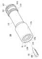
- Figure 1is a side cross-sectional view showing the main configuration of the handpiece of the skin care device according to an embodiment of the present invention.
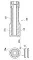
- FIG. 2is a diagram illustrating an example configuration of a tip module used in the handpiece illustrated in FIG. 1.
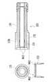
- FIG. 3is a view illustrating an operation of the handpiece illustrated in FIG. 1, in which external air is sucked through the air intake passage by air intake and the skin is pulled by a negative pressure.
- FIG. 4is a view illustrating inflow and injection of a solution when the tip module rotates according to the operation of the driving motor as the operation of the handpiece shown in FIG. 1.
- 5 to 7are views for explaining the handpiece of the skin care device according to another embodiment of the present invention.
- FIG. 1is a side cross-sectional view showing the main configuration of the handpiece of the skin care device according to an embodiment of the present invention
- Figure 2is a view showing an example configuration for the tip module used in the handpiece shown in FIG. to be.
- the handpiece of the skin care devicebasically includes a body portion 210 and the body portion 210 installed inside an outer case (not shown) of the handpiece. It is configured to include a tip module 100 is detachably mounted on one side of the.
- the body portion 210may be configured to include a solution inlet 214 and an air outlet 216 having a detachable hole 212 at one side and communicating with the detachable hole 212.
- the tip module 100is mounted to be detachably attached to the detachable hole 212 of the body portion 210, and is operated in contact with the skin of the subject and is disposable (that is, if used for one subject) When performing the procedure, the tip module is configured to remove the tip module and refit the new tip module.
- the tip module 100may be configured to include a cylinder body 110 detachably mounted to the detachable hole 212 and an inner cylinder 130 having a hollow interior inside the cylinder body 110. have.
- the hollow inside of the inner cylinder 130is configured to communicate with the solution inlet 214 of the body 210, the inner cylinder ( Preferably, the hollow interior of the 130 is formed as a solution injection passage F1 through which a solution flowing from the solution inlet 214 flows.
- the solutionis a liquid or gaseous drug is injected into the interior through the pores of the skin to act as a useful action to remove the waste in the pores or improve the skin, means that the drug is mixed with compressed air You may.
- the solution inlet 214 of the body portion 210is connected to an external solution source (not shown) through a tube or tube, and the solution inflow through the tube or tube from the solution source. It is preferable that the predetermined solution prepared in advance to the unit 214 is supplied to be introduced into the tip module.
- the air discharge portion 216 of the body portion 210is connected to an external suction pump (not shown), the air is sucked from the tip module 100 in accordance with the operation of the suction pump is the air discharge portion 216 It is preferable that the air is sucked toward the suction pump through a).
- the air suction flow path F2is formed to allow air to flow between the cylinder body 110 and the inner cylinder 130 to be discharged to the air discharge part 216 according to the driving of an external suction pump. It is preferable.
- the tip module 100includes a solution injection unit provided at an end of the inner cylinder 130 to allow the solution flowing through the solution injection passage F1 to be injected to the outside.
- FIGS. 1 and 2illustrate the interference fitting member 150 as an example.
- the interference fitting member 150is shown in more detail in FIG. 2.
- the interference fitting member 150 as the solution injection partis fitted to the end of the inner cylinder 130 to block the solution injection flow path F1, and the interference fitting member (
- the solution flowing in the solution injection passage F1is provided with an injection groove 158 formed with at least one groove along the longitudinal direction of the 150 through the injection groove 158 of the interference fitting member 150. Can be sprayed on.
- a small holeis formed between the interference fitting member 150 and the inner cylinder 130 by the injection groove 158 so that the solution can be injected to the outside.
- the end of the tip module 100is in contact with the skin and injection of the solution into the skin through the injection groove 158 of the interference fitting member 150, such as the surrounding air and the waste from the skin
- the materialmay be sucked through the air suction passage F2 and discharged to the air discharge unit 216 according to the driving of an external suction pump.
- the injection of the solutionis performed through the pores of the skin, and the solution is injected into the skin, thereby effectively inhaling and discharging the material such as waste products, thereby realizing the effect of beauty of the skin as well as washing the skin.
- the cylinder body 110 of the tip module 100is mounted around the circumferential direction on the opposite side to which the interference fitting member 150 of the cylinder body 110 is fitted as shown in FIGS. 1 and 2.
- the groove portion 113 formed between the first sealing member 111a and the second sealing member 111b, and the groove portion 113is preferably configured to include at least one communication hole 112 formed to communicate with the hollow interior of the inner cylinder (130).
- the tip module 100when the tip module 100 is mounted in the detachable hole 212 of the body portion 210, the first sealing member 111a and the second sealing member 111b.
- the solution inlet 214 of the body portion 210is in communication with the groove 113 so that the solution flowing through the solution inlet 214 is filled in the groove 113 so as to be sealed by the communication hole ().
- Through 112may be introduced into the solution injection passage (F1) of the hollow interior of the inner cylinder (130).
- the groove 113is sealed by the first sealing member 111a and the second sealing member 111b to communicate with only the solution inlet 214, thereby allowing the 'rotation of the tip module 100' to be described later.
- the solution introduced through the solution inlet 214may be stably introduced into the solution injection passage F1 through the communication hole 112 in the groove 113.
- FIG. 3 and 4show the operation of the handpiece of the skin care device according to the embodiment of the present invention having the configuration as shown in FIG.
- the cylinder body 110 of the tip module 100further has an outer diameter so that the tip module 100 is exposed to the outside of the detachable hole 212 when the tip module 100 is mounted in the detachable hole 212. It is preferably configured to include an exposed portion 110a formed to be enlarged and a stepped portion 110c formed to step inwardly to the end portion 110b of the exposed portion.
- the airis sucked through the air intake passage F2, so that the negative pressure formed in the stepped portion 110c pulls the skin, and the pores of the skin can be expanded, and the solution injection unit (the interference fitting member 150) is opened. It is desirable that the solution injected by injection can better penetrate into the pores of the skin.
- the handpiece of the skin care devicecan be while the tip module 100 as described above while the injection of the solution and the suction of air while rotating by a motor.
- the tip module 100rotates to inject the solution and inhale air as described above, the solution may be injected into the skin evenly and more effectively.
- the handpiece of the skin care deviceis provided at the rear of the detachable hole 212 in which the tip module 100 of the body portion 210 is mounted, and the driving shaft 410. It is configured to include a drive motor 400 for rotating the shaft and the shaft coupling portion 420 coupled to the drive shaft 410 and rotates with the drive shaft 410 and the tip module 100 is coupled to the end thereof. desirable.
- the tip module 100 coupled to the shaft coupling portion 420rotates while the shaft coupling portion 420 rotates by the driving shaft 410 according to the driving of the driving motor 400.
- the tip module 100is rotated while the skin of the tip module 100 is pulled to the stepped portion 110c by the negative pressure through the air suction passage F2 while the end of the tip module 100 is in contact with the skin.
- the solution introduced through the 214is introduced into the solution injection passage F1 through the communication hole 112 in the groove portion 113 so as to be injected into the skin through the solution injection unit (an interference fitting member 150). It can be.
- the waste of the skinis sucked with the air is introduced into the air space portion (AC) to the rear end side of the tip module 100 through the air suction flow path (F2) and the air introduced into the air space portion (AC) is It can be discharged to the outside through the air discharge unit 216 by the external suction pump.
- a tip coupling portion 422is formed at an end of the shaft coupling portion 420, and a coupling that can be coupled to the tip coupling portion 422 at a rear end of the tip module 100.
- the tip module 100is configured to be formed so that the tip module 100 is inserted into the detachable hole 212 so that the coupling part 134 is fitted to the tip coupling part 422. ) May be rotated by the drive shaft 410 and the shaft coupling portion 420.
- the tip module 100has friction with the keratin of the skin as the tip module 100 rotates as shown in FIG. 5 at the end 130a of the inner cylinder 130. This is the case where the friction surface A1 or A2 is formed to cause the exfoliation.
- the friction surfacemay be formed at the end 130a of the inner cylinder, but may include both the solution injection unit (the interference fitting member 150 described above) as well as the 'closed end of the inner cylinder' and the 'combining cap' to be described later. ) May be formed, or may be formed in both parts. Since both parts are in contact with the skin, the friction surface is formed to exfoliate the dead skin, and the injection of the solution is performed as described above, so that the injection of the solution can be made more effectively.
- the embossed portion A1may be formed or the toothed portion A2 may be formed.
- the tip module 100is characterized in that the inner cylinder 131 is configured such that its end is closed, the solution injection portion is formed in the closed end of the inner cylinder 131 This is the case when it is implemented as at least one injection hole Nh1.
- the solution injection unitis configured such that the inner cylinder itself is closed at the end instead of the interference fitting member, and a small hole is drilled so that the solution can be injected at the closed end.
- the solution flowing in the solution injection passage F1is operated to be injected to the outside through the injection hole Nh1.
- the tip module 100 in this embodimentis configured by the inner cylinder 132 is coupled to the coupling cap 133, the coupling cap 133 is removable as shown in FIG. Can be combined.
- At least one injection hole Nh2is formed at an end of the coupling cap 133 so that the solution flowing in the solution injection passage F1 is sprayed to the outside through the injection hole Nh2.
- the handpiece of the skin care deviceAs described above, the handpiece of the skin care device according to an embodiment of the present invention, the injection of the solution through the pores of the skin, etc. in the Needles method and at the same time the solution is injected into the skin material such as waste products By effectively inhaling and discharging this coming out there is a feature that can realize the effect of skin care as well as skin care.
- the present inventioncan be made by injection injection and air intake of the solution as described above while rotating the tip module in accordance with the drive of the drive motor has the feature that can be more effective skin cleaning and skin improvement.
- the handpiece of the skin care device according to the present inventionis an industry in the field related to skin aesthetics, which can clean and improve the skin by spraying and injecting a predetermined solution in contact with the skin without inserting a needle into the skin of the subject. Phase availability.
Landscapes
- Health & Medical Sciences (AREA)
- Heart & Thoracic Surgery (AREA)
- Engineering & Computer Science (AREA)
- Public Health (AREA)
- General Health & Medical Sciences (AREA)
- Veterinary Medicine (AREA)
- Anesthesiology (AREA)
- Hematology (AREA)
- Life Sciences & Earth Sciences (AREA)
- Animal Behavior & Ethology (AREA)
- Biomedical Technology (AREA)
- Vascular Medicine (AREA)
- Surgery (AREA)
- Pulmonology (AREA)
- Mechanical Engineering (AREA)
- Oral & Maxillofacial Surgery (AREA)
- Epidemiology (AREA)
- Massaging Devices (AREA)
- Media Introduction/Drainage Providing Device (AREA)
- Coating Apparatus (AREA)
- Body Washing Hand Wipes And Brushes (AREA)
- Devices For Medical Bathing And Washing (AREA)
Abstract
Description
Translated fromKorean본 발명은 피부미용장치의 핸드피스에 관한 것으로, 보다 상세하게는 피부 미용을 위한 소정의 솔루션(Solution)이 분사되어 피부 내부로 주입될 수 있도록 하여 피부의 세척과 피부 미용에 좋은 약물의 주입 등이 가능하도록 하는 피부미용장치에 이용되는 핸드피스에 관한 것이다.The present invention relates to a handpiece of a skin care device, and more particularly, a predetermined solution (Solution) for the beauty of the skin is sprayed to be injected into the skin to clean the skin and injection of a good drug for skin beauty, etc. It relates to a handpiece used in a skin care device to make this possible.
최근 들어 남녀노소를 불문하고 피부에 대한 관심이 증폭됨에 따라 피부관리에 관계되는 다양한 장치가 개발됨과 동시에 피부관련병원과 피부관리시술업체들이 많이 생겨나고 있다.Recently, as the interest in the skin is amplified regardless of age or gender, various devices related to skin care have been developed, and skin-related hospitals and skin care procedures companies are emerging.
최근에 가장 널리 알려진 피부시술방법은 마이크로니들 시술과 종래의 프렉셔널 레이저시술이 결합된 것으로, 이는 아주 미세한 바늘(마이크로니들)을 피부에 삽입하여 치료기둥을 만듦과 동시에 고주파(RF)를 제공함에 따라 피부 내에 국소적인 열손상을 가하여 상피부터 진피에 이르기까지 피부의 재생을 촉진시키기 위한 미세상처들을 만들어 내고 이 미세상처들이 세포의 성장인자를 유도하여 피부의 자연치유 및 재생을 극대화하는 방법이다.Recently, the most widely known skin treatment method is a combination of a microneedle treatment and a conventional fractional laser treatment, which inserts a very fine needle (microneedle) into the skin to create a therapeutic pillar and at the same time provide high frequency (RF). Therefore, by applying local heat damage in the skin to create micro-wounds to promote the regeneration of the skin from the epithelium to the dermis, these micro-wounds induce growth factors of the cells to maximize the natural healing and regeneration of the skin.
통상적으로 고주파 제공을 위한 전극 역할을 하는 마이크로니들을 통해 고주파를 인체조직에 가하게 되면 마이크로니들 주위의 조직 내부에서 고주파에 의한 마찰열이 발생되어 진피층에 콜라겐 성분을 단단하게 뭉치게 함과 동시에 새로운 콜라겐 형성을 촉진하게 되며, 이로 인해 주름이 펴지고 모공이 축소되게 되어 피부를 개선하게 된다.In general, when high frequency is applied to human tissues through the microneedle serving as an electrode for providing high frequency, friction heat is generated inside the tissue around the microneedles, thereby solidifying the collagen component in the dermis and forming new collagen. This will promote wrinkles and shrink pores, improving skin.
전술한 피부시술방법은 표피에 화상을 입히지 않으면서 목적하는 부위에 높은 열에너지를 전달하여 콜라겐과 탄력섬유를 재생시킬 수 있어 여드름, 여드름 흉터, 잔주름, 깊은 주름, 모공축소 치료에 매우 효과적인 것으로 알려져 있다. 또한 혈액순환을 원활하게 하여 지방층의 연소를 촉진시키고 림프계의 활동을 활성화시켜 비만치료를 가능하게 한다.The above-described skin treatment method is known to be very effective in treating acne, acne scars, fine lines, deep wrinkles, and shrinking pores because it can regenerate collagen and elastic fibers by delivering high heat energy to a desired area without causing burns on the epidermis. . In addition, it facilitates blood circulation, promotes the burning of fat layer and activates the activity of the lymphatic system, thereby enabling the treatment of obesity.
전술한 피부시술을 가능하게 하는 피부미용치료장치는, 특허등록 제10-0946363호(2010.03.02.)에 공개된 바와 같이, 고주파발진부가 구비된 본체와, 본체에 일단이 접속되는 케이블과, 케이블의 타단에 결합되고 선단에는 본체의 주파부발진부와 전기적으로 연결되고 피부 내로 삽입되어 고주파를 제공하는 다수의 마이크로니들이 일체로 선형 이동 가능하게 설치되는 핸드피스를 포함하여 이루어진다.Skin beauty treatment apparatus that enables the above-described skin treatment, as disclosed in Patent Registration No. 10-0946363 (2010.03.02.), A main body having a high frequency oscillation unit, a cable connected to one end of the main body, It is coupled to the other end of the cable and the front end comprises a handpiece which is electrically connected to the frequency oscillation portion of the main body and inserted into the skin to provide a high frequency of a plurality of microneedle integrally linearly movable.
마이크로니들은 케이블에 의해 주파부발진부와 연결되는 인쇄회로기판에 일정간격을 두고 이격된 상태로 결합되고 그 중 일부는 (+)극은 전극으로 작용하고 나머지 일부는 (-)극 전극으로 작용하도록 구성된다.The microneedle is connected to the printed circuit board connected to the frequency oscillation part by a cable at a predetermined interval, and some of the positive electrode acts as an electrode and the other part acts as a negative electrode. It is composed.
그러나 종래의 마이크로니들의 경우에는 시술을 요하는 피부조직의 표면이 평면이 아니라 곡면임에도 불구하고 다수의 마이크로니들이 동일한 길이로 형성됨에 따라, 그 중 일부의 마이크로니들은 피부 내로 삽입되어 고주파를 제공하지만 나머지 일부의 마이크로니들은 피부 내로 제대로 삽입되지 못함에 따라 오히려 피부가 열에 의해 손상되는 문제점이 있었다.However, in the case of the conventional microneedle, even though the surface of the skin tissue requiring the procedure is not a flat but curved surface, as a plurality of microneedles are formed in the same length, some of the microneedles are inserted into the skin to provide a high frequency. Some of the microneedles are not properly inserted into the skin, rather, the skin is damaged by heat.
상술한 바와 같이, 종래 피부 개선을 위한 장치들은 복잡한 구조를 이룸과 동시에 각각 특유의 단점을 지니고 있어, 보다 단순한 구성을 지니면서 안정적 작동이 가능한 피부세척장치의 개발이 필요하였다.As described above, the conventional devices for improving skin have a complex structure and at the same time have unique disadvantages, and thus, it is necessary to develop a skin washing apparatus having a simpler structure and capable of stable operation.
<선행기술문헌><Preceding technical literature>
(특허문헌1) 한국등록실용신안 20-0412689 (2006.03.23)(Patent Document 1) Korea Registration Utility Model 20-0412689 (2006.03.23)
(특허문헌2) 한국등록특허 10-1437563 (2014.08.28)(Patent Document 2) Korea Patent Registration 10-1437563 (2014.08.28)
본 발명은 피부에 팁모듈을 접촉시켜 솔루션을 분사하는 동시에 주변의 공기 및 피부로부터 빠져나오는 노폐물 등의 물질이 흡입되도록 하여, 통증과 흉터 등을 유발하는 니들(Needle)을 이용하지 않고도 소정의 솔루션을 이용하여 피부에 대한 세척이나 피부 개선 등의 효과를 얻을 수 있도록 하는 피부미용장치의 핸드피스를 제공하기 위한 것이다.The present invention injects a solution by contacting the tip module to the skin and at the same time inhales substances such as waste air from the surrounding air and the skin, thereby allowing a predetermined solution without using a needle that causes pain and scarring. It is to provide a handpiece of a skin care device that can be used to obtain effects such as washing or skin improvement for the skin.
나아가, 본 발명은 피부에 대한 솔루션의 분사 주입이 더욱 효과적으로 이루어지며 피부 개선 효과를 더욱 증대시키도록 피부에 접촉되는 팁모듈을 회전시키도록 하면서도 그 회전하는 팁모듈을 통해 솔루션이 안정적으로 분사될 수 있도록 하는 피부미용장치의 핸드피스를 제공하기 위한 것이다.Furthermore, the present invention allows the injection injection of the solution to the skin more effectively, and while rotating the tip module in contact with the skin to further increase the skin improvement effect, the solution can be stably sprayed through the rotating tip module It is to provide a handpiece of the skin care device.
본 발명의 일 실시예에 따른 피부미용장치의 핸드피스는, 일측에 착탈홀을 구비하고 상기 착탈홀과 연통되는 솔루션 유입부와 공기 배출부를 형성하는 몸체부와, 상기 몸체부의 착탈홀에 장착되어 사용되는 일회용의 팁모듈을 포함하여 구성되며, 상기 팁모듈은, 상기 착탈홀에 착탈 가능하도록 장착되는 실린더몸체와, 상기 실린더몸체 내부에 중공된 내부를 갖는 내부실린더를 구비하고, 상기 팁모듈이 상기 착탈홀에 장착되었을 때 상기 내부실린더의 중공된 내부가 상기 솔루션 유입부와 연통되도록 구성되어 상기 내부실린더의 중공된 내부가 상기 솔루션 유입부로부터 유입되는 솔루션이 유동하는 솔루션 주입유로로서 형성되며, 외부의 흡입펌프의 구동에 따라 상기 실린더몸체와 상기 내부실린더 사이에 공기가 유동하여 상기 공기 배출부로 배출되도록 하는 공기흡입유로가 형성되도록 구성되고, 상기 내부실린더의 단부에 구비되어 상기 솔루션 주입유로를 유동하는 솔루션이 외부로 분사되도록 하는 솔루션 분사부를 포함하여, 상기 팁모듈의 단부가 피부에 접촉하여 상기 솔루션 분사부를 통해 상기 솔루션을 상기 피부에 분사주입하면서 주변의 공기 및 상기 피부로부터 빠져나오는 물질이 상기 흡입펌프의 구동에 따라 상기 공기흡입유로를 통해 흡입되어 상기 공기 배출부로 배출되도록 하는 것을 특징으로 한다.The handpiece of the skin care device according to an embodiment of the present invention includes a body part having a detachable hole on one side and forming a solution inlet and an air outlet in communication with the detachable hole, and mounted in the detachable hole of the body part. It is configured to include a disposable tip module to be used, the tip module is provided with a cylinder body that is detachably mounted to the removable hole, and the inner cylinder having a hollow inside the cylinder body, the tip module is When the hollow inside of the inner cylinder is configured to communicate with the solution inlet when the mounting hole is mounted in the removable hole is formed as a solution inlet flow path through which the solution flowing from the solution inlet flows, As the external suction pump is driven, air flows between the cylinder body and the inner cylinder to the air discharge part. It is configured to form an air suction passage to be discharged, including a solution injection portion provided at the end of the inner cylinder to the solution flowing in the solution injection flow path to the outside, the end of the tip module is in contact with the skin Injecting the solution into the skin through the solution injection unit is characterized in that the surrounding air and the substance exiting from the skin is sucked through the air intake passage in accordance with the driving of the suction pump is discharged to the air discharge unit do.
또한 바람직하게는, 상기 실린더몸체는, 상기 실린더몸체의 원주방향 둘레에 장착되는 제1 실링부재 및 제2 실링부재와, 상기 제1 실링부재 및 제2 실링부재 사이에 형성되는 홈부와, 상기 홈부에 형성되어 상기 내부실린더의 중공된 내부와 연통되도록 형성되는 적어도 하나의 연통홀을 포함하여, 상기 팁모듈이 상기 착탈홀에 장착되었을 때, 상기 제1 실링부재 및 제2 실링부재에 의해 밀폐되어 상기 솔루션 유입부가 상기 홈부와 연통됨으로써 상기 솔루션 유입부를 통해 유입되는 솔루션이 상기 홈부에서 상기 연통홀을 통해 상기 내부실린더의 중공된 내부의 상기 솔루션 주입유로로 유입되도록 구성되는 것을 특징으로 한다.Also preferably, the cylinder body may include a first sealing member and a second sealing member mounted around the circumferential direction of the cylinder body, a groove portion formed between the first sealing member and the second sealing member, and the groove portion. Including at least one communication hole is formed in the communication with the hollow interior of the inner cylinder, when the tip module is mounted in the detachable hole, is sealed by the first sealing member and the second sealing member The solution inlet is communicated with the groove, so that the solution introduced through the solution inlet is configured to be introduced into the solution injection passage in the hollow interior of the inner cylinder through the communication hole in the groove.
또한 바람직하게는, 상기 실린더몸체는, 상기 팁모듈이 상기 착탈홀에 장착되었을 때 상기 착탈홀의 외부에 노출되는 노출부와, 상기 노출부의 단부에 안쪽으로 단차지도록 형성되는 단차부를 포함하고, 상기 내부실린더의 단부와 상기 단차부 사이에 길이 방향을 따라 상기 공기흡입유로가 형성되어, 상기 피부에 상기 노출부의 단부가 접촉되어 상기 흡입펌프의 구동에 따라 상기 공기흡입유로를 통해 공기가 흡입됨으로써 상기 단차부에 음압이 형성되어 상기 피부가 상기 음압에 의해 당겨져서 상기 내부실린더의 단부 및 상기 솔루션 분사부에 밀착되도록 하는 것을 특징으로 한다.Also preferably, the cylinder body may include an exposed part exposed to the outside of the detachable hole when the tip module is mounted to the detachable hole, and a stepped part formed to step inwardly at an end of the exposed part. The air suction passage is formed along the longitudinal direction between the end of the cylinder and the stepped portion, and the end portion of the exposed portion is in contact with the skin and the air is sucked through the air suction passage according to the driving of the suction pump. A negative pressure is formed in the part so that the skin is pulled by the negative pressure to be in close contact with the end portion of the inner cylinder and the solution injection part.
또한 바람직하게는, 상기 솔루션 분사부는, 상기 솔루션 주입유로를 막도록 상기 내부실린더의 단부에 억지끼움되는 억지끼움부재를 포함하며, 상기 억지끼움부재의 길이 방향을 따라 적어도 하나의 홈으로 형성되는 주입홈부를 구비하여 상기 솔루션 주입유로에서 유동하는 솔루션이 상기 억지끼움부재의 주입홈부를 통해 외부로 분사되도록 하는 것을 특징으로 한다.Also preferably, the solution injection unit may include an interference fitting member that is fitted to the end of the inner cylinder to block the solution injection passage, and is formed with at least one groove along the longitudinal direction of the interference fitting member. It is characterized by having a groove portion so that the solution flowing in the solution injection passage is injected to the outside through the injection groove of the interference fitting member.
또한 바람직하게는, 상기 솔루션 분사부는, 적어도 하나의 분사홀을 형성하며 상기 내부실린더의 단부에 결합되어 상기 솔루션 주입유로에서 유동하는 솔루션이 상기 분사홀을 통해 외부로 분사되도록 하는 결합캡을 포함하는 것을 특징으로 한다.Also preferably, the solution jetting portion may include a coupling cap forming at least one injection hole and coupled to an end of the inner cylinder to allow a solution flowing in the solution injection passage to be injected to the outside through the injection hole. It is characterized by.
또한 바람직하게는, 상기 내부실린더는 그 단부가 폐쇄되도록 구성되며, 상기 솔루션 분사부는, 상기 내부실린더의 폐쇄된 단부에 형성되는 적어도 하나의 분사홀을 포함하여, 상기 솔루션 주입유로에서 유동하는 솔루션이 상기 분사홀을 통해 외부로 분사되도록 하는 것을 특징으로 한다.Also preferably, the inner cylinder is configured such that an end thereof is closed, and the solution injection unit includes at least one injection hole formed in the closed end of the inner cylinder, so that the solution flowing in the solution injection passage is Characterized in that the injection to the outside through the injection hole.
또한 바람직하게는, 상기 몸체부의 타측에 구비되어 구동축을 회전시키는 구동모터와, 상기 구동축에 결합하여 상기 구동축과 함께 회전하며 그 단부에 상기 팁모듈이 결합하는 축결합부를 포함하여, 상기 구동모터의 구동에 따라 상기 구동축에 의해 상기 축결합부가 회전하면서 상기 축결합부에 결합된 상기 팁모듈을 회전시키며, 상기 팁모듈의 단부가 피부에 접촉한 상태로 상기 팁모듈이 회전하면서 상기 솔루션 유입부를 통해 유입되는 솔루션이 상기 홈부에서 상기 연통홀을 통해 상기 솔루션 주입유로로 유입되어 상기 솔루션 분사부를 통해 상기 피부에 분사주입되도록 하는 것을 특징으로 한다.Also preferably, the drive motor is provided on the other side of the body portion to rotate the drive shaft, and coupled to the drive shaft to rotate with the drive shaft and the shaft coupled portion coupled to the tip module at the end of the drive motor, As the drive shaft rotates the tip module coupled to the shaft coupling portion by the drive shaft, the tip module rotates while the tip module rotates in contact with the skin through the solution inlet. The solution is introduced into the solution injection flow path through the communication hole in the groove portion is characterized in that the injection injection into the skin through the solution injection unit.
또한 바람직하게는, 상기 내부실린더의 단부 및 상기 솔루션 분사부의 단부 중 적어도 하나에 형성되어 상기 팁모듈이 회전함에 따라 상기 피부의 각질과 마찰을 일으켜 상기 각질을 벗겨내도록 하는 마찰표면을 더 포함하는 것을 특징으로 한다.Also preferably, at least one of the end of the inner cylinder and the end of the solution injecting portion further comprises a friction surface to rub off the keratin by friction with the keratin of the skin as the tip module rotates. It features.
본 발명의 일 실시예에 따른 피부미용장치의 핸드피스는, 피부에 팁모듈을 접촉시켜 솔루션을 분사하는 동시에 주변의 공기 및 피부로부터 빠져나오는 노폐물 등의 물질이 흡입되도록 하여, 통증과 흉터 등을 유발하는 니들(Needle)을 이용하지 않고도 소정의 솔루션을 이용하여 피부에 대한 세척이나 피부 개선 등의 효과를 얻을 수 있도록 하는 효과가 있다.Handpiece of the skin care device according to an embodiment of the present invention, by contacting the tip module to the skin to spray the solution and at the same time to inhale the substances such as the surrounding air and wastes from the skin, pain and scars, etc. There is an effect that it is possible to obtain the effect of washing or improving the skin using a predetermined solution without using the needle (inducing needle).
또한, 본 발명의 일 실시예에 따른 피부미용장치의 핸드피스는, 피부에 대한 솔루션의 분사 주입이 더욱 효과적으로 이루어지며 피부 개선 효과를 더욱 증대시키도록 피부에 접촉되는 팁모듈을 회전시키도록 하면서도 그 회전하는 팁모듈을 통해 솔루션이 안정적으로 분사될 수 있도록 하는 효과가 있다.In addition, the handpiece of the skin care device according to an embodiment of the present invention, while the injection injection of the solution to the skin is made more effectively and while rotating the tip module in contact with the skin to further increase the skin improvement effect The rotating tip module has the effect of reliably spraying the solution.
도 1은 본 발명의 일 실시예에 따른 피부미용장치의 핸드피스의 주요 구성에 관하여 나타낸 측단면도이다.Figure 1 is a side cross-sectional view showing the main configuration of the handpiece of the skin care device according to an embodiment of the present invention.
도 2는 도 1에 도시된 핸드피스에 이용되는 팁모듈에 대한 일 예의 구성을 나타낸 도면이다.FIG. 2 is a diagram illustrating an example configuration of a tip module used in the handpiece illustrated in FIG. 1.
도 3은 도 1에 도시된 핸드피스의 동작으로서 공기의 흡입에 의해 공기흡입유로를 통해 외부의 공기가 흡입되고 피부가 음압에 의해 당겨지는 것을 나타내는 도면이다.FIG. 3 is a view illustrating an operation of the handpiece illustrated in FIG. 1, in which external air is sucked through the air intake passage by air intake and the skin is pulled by a negative pressure.
도 4는 도 1에 도시된 핸드피스의 동작으로서 구동모터의 동작에 따라 팁모듈이 회전하는 경우에 있어서 솔루션의 유입 및 분사에 관하여 나타내는 도면이다.FIG. 4 is a view illustrating inflow and injection of a solution when the tip module rotates according to the operation of the driving motor as the operation of the handpiece shown in FIG. 1.
도 5 내지 도 7은 본 발명의 다른 실시예들에 따른 피부미용장치의 핸드피스에 관하여 설명하기 위한 도면들이다.5 to 7 are views for explaining the handpiece of the skin care device according to another embodiment of the present invention.
이하 본 발명의 목적이 구체적으로 실현될 수 있는 본 발명의 바람직한 실시예를 첨부된 도면을 참조하여 설명한다. 본 실시예를 설명함에 있어서, 동일 구성에 대해서는 동일 명칭 및 동일 부호가 사용되며 이에 따른 부가적인 설명은 생략하기로 한다. 먼저, 도 1 및 도 2를 참고하여 본 발명의 바람직한 실시예에 따른 구성 및 작용을 설명하기로 한다.DETAILED DESCRIPTION Hereinafter, exemplary embodiments of the present invention will be described in detail with reference to the accompanying drawings. In the description of this embodiment, the same name and the same reference numerals are used for the same configuration and additional description thereof will be omitted. First, with reference to Figures 1 and 2 will be described the configuration and operation according to a preferred embodiment of the present invention.
도 1은 본 발명의 일 실시예에 따른 피부미용장치의 핸드피스의 주요 구성에 관하여 나타낸 측단면도이고, 도 2는 도 1에 도시된 핸드피스에 이용되는 팁모듈에 대한 일 예의 구성을 나타낸 도면이다.1 is a side cross-sectional view showing the main configuration of the handpiece of the skin care device according to an embodiment of the present invention, Figure 2 is a view showing an example configuration for the tip module used in the handpiece shown in FIG. to be.
도 1에 도시된 바와 같이 본 발명의 일 실시예에 따른 피부미용장치의 핸드피스는 기본적으로 상기 핸드피스의 외부 케이스(미도시) 내부에 설치되는 몸체부(210) 및 상기 몸체부(210)의 일측에 착탈 가능하도록 장착되는 팁모듈(100)을 포함하여 구성된다.As shown in FIG. 1, the handpiece of the skin care device according to the exemplary embodiment of the present invention basically includes a
상기 몸체부(210)는 일측에 착탈홀(212)을 구비하고 상기 착탈홀(212)과 연통되는 솔루션 유입부(214)와 공기 배출부(216)를 형성하도록 구성될 수 있다.The
그리고, 상기 팁모듈(100)은 상기 몸체부(210)의 착탈홀(212)에 착탈 가능하도록 장착되는데, 피시술자의 피부에 접촉되어 작동되며 일회용(disposable), 즉 어느 한 피시술자에 대해 사용하였다면 다른 피시술자에게 시술할 때에는 해당 팁모듈을 제거하고 새로운 팁모듈을 다시 끼워서 사용하도록 구성되는 것이다.In addition, the
상기 팁모듈(100)은 상기 착탈홀(212)에 착탈 가능하도록 장착되는 실린더몸체(110)와, 상기 실린더몸체(110) 내부에 중공된 내부를 갖는 내부실린더(130)를 구비하도록 구성될 수 있다.The
상기 팁모듈(100)이 상기 착탈홀(212)에 장착되었을 때 상기 내부실린더(130)의 중공된 내부가 상기 몸체부(210)의 솔루션 유입부(214)와 연통되도록 구성되어 상기 내부실린더(130)의 중공된 내부가 상기 솔루션 유입부(214)로부터 유입되는 솔루션(Solution)이 유동하는 솔루션 주입유로(F1)로서 형성되는 것이 바람직하다.When the
여기서, 상기 솔루션(Solution)은 액체 또는 기체 상태의 약물로서 피부의 모공 등을 통해 내부로 주입되어 모공 내의 노폐물을 제거하거나 피부의 개선에 유용한 작용하는 것이며, 약물이 압축공기와 섞인 상태의 것을 의미할 수도 있다.Here, the solution (Solution) is a liquid or gaseous drug is injected into the interior through the pores of the skin to act as a useful action to remove the waste in the pores or improve the skin, means that the drug is mixed with compressed air You may.
도면상으로 도시되지는 않았지만, 상기 몸체부(210)의 솔루션 유입부(214)는 외부의 솔루션 공급원(미도시)과 튜브나 관 등으로 연결되어 상기 솔루션 공급원으로부터 튜브나 관을 통해 상기 솔루션 유입부(214)로 미리 준비된 소정의 솔루션이 공급되어 팁모듈로 유입될 수 있도록 구성되는 것이 바람직하다.Although not shown in the drawings, the
또한, 상기 몸체부(210)의 공기 배출부(216)는 외부의 흡입펌프(미도시)와 연결되어 상기 흡입펌프의 동작에 따라 팁모듈(100)로부터 공기가 흡입되어 상기 공기 배출부(216)를 통해 상기 흡입펌프 쪽으로 공기가 빨려 갈 수 있도록 구성되는 것이 바람직하다.In addition, the
한편, 상기한 바와 같이 상기 팁모듈(100)이 상기 착탈홀(212)에 장착되었을 때 상기 솔루션 유입부(214)로 유입되는 솔루션(Solution)이 상기 솔루션 주입유로(F1)로 유입되는 것과 함께, 외부의 흡입펌프의 구동에 따라 상기 실린더몸체(110)와 상기 내부실린더(130) 사이에 공기가 유동하여 상기 공기 배출부(216)로 배출되도록 하는 공기흡입유로(F2)가 형성되도록 구성되는 것이 바람직하다.Meanwhile, as described above, when the
그리고, 팁모듈(100)은 내부실린더(130)의 단부에 구비되어 상기 솔루션 주입유로(F1)를 유동하는 솔루션이 외부로 분사되도록 하는 솔루션 분사부를 포함한다.In addition, the
여기서 상기 솔루션 분사부는 여러 가지 예로써 구현될 수 있는데, 도 1 및 도 2에서는 그 일 예로서 억지끼움부재(150)에 대해 나타내고 있다.Here, the solution injection unit may be implemented by various examples, and FIGS. 1 and 2 illustrate the
상기 억지끼움부재(150)에 대해서는 도 2에서 좀 더 구체적으로 나타내고 있다.The
도 1 및 도 2에 도시된 바와 같이 상기 솔루션 분사부로서 억지끼움부재(150)는 상기 솔루션 주입유로(F1)를 막도록 상기 내부실린더(130)의 단부에 억지끼움되며, 상기 억지끼움부재(150)의 길이 방향을 따라 적어도 하나의 홈으로 형성되는 주입홈부(158)를 구비하여 상기 솔루션 주입유로(F1)에서 유동하는 솔루션이 상기 억지끼움부재(150)의 주입홈부(158)를 통해 외부로 분사되도록 할 수 있다.As shown in FIGS. 1 and 2, the
즉, 상기 억지끼움부재(150)와 내부실린더(130) 사이에 주입홈부(158)에 의하여 솔루션이 외부로 분사될 수 있는 작은 홀이 형성되는 것이다.That is, a small hole is formed between the
따라서, 상기 팁모듈(100)의 단부가 피부에 접촉하여 상기 억지끼움부재(150)의 주입홈부(158)를 통해 솔루션을 상기 피부에 분사주입하면서 주변의 공기 및 상기 피부로부터 빠져나오는 노폐물 등의 물질이 외부의 흡입펌프의 구동에 따라 상기 공기흡입유로(F2)를 통해 흡입되어 상기 공기 배출부(216)로 배출되도록 할 수 있다.Therefore, the end of the
이와 같이 피부의 모공 등을 통해 솔루션의 분사주입이 이루어지는 동시에 상기 피부에 솔루션이 주입됨으로써 노폐물 등의 물질이 나오는 것을 효과적으로 흡입하여 배출함으로써 피부에 대한 세척은 물론 피부 미용의 효과를 구현할 수 있는 것이다.As such, the injection of the solution is performed through the pores of the skin, and the solution is injected into the skin, thereby effectively inhaling and discharging the material such as waste products, thereby realizing the effect of beauty of the skin as well as washing the skin.
한편, 상기 팁모듈(100)의 실린더몸체(110)는, 도 1 및 도 2에 도시된 바와 같이 상기 실린더몸체(110)의 억지끼움부재(150)가 끼워지는 반대쪽에서 원주방향 둘레에 장착되는 제1 실링부재(111a) 및 제2 실링부재(111b)와, 상기 제1 실링부재(111a) 및 제2 실링부재(111b) 사이에 형성되는 홈부(113)와, 상기 홈부(113)에 형성되어 상기 내부실린더(130)의 중공된 내부와 연통되도록 형성되는 적어도 하나의 연통홀(112)을 포함하도록 구성됨이 바람직하다.On the other hand, the
따라서, 도 1 및 도 2에 도시된 바와 같이 상기 팁모듈(100)이 몸체부(210)의 착탈홀(212)에 장착되었을 때, 상기 제1 실링부재(111a) 및 제2 실링부재(111b)에 의해 밀폐되어 몸체부(210)의 솔루션 유입부(214)가 상기 홈부(113)와 연통됨으로써 상기 솔루션 유입부(214)를 통해 유입되는 솔루션이 상기 홈부(113)에 채워지면서 연통홀(112)을 통해 상기 내부실린더(130)의 중공된 내부의 솔루션 주입유로(F1)로 유입되도록 할 수 있다.Therefore, as shown in FIGS. 1 and 2, when the
이와 같이 제1 실링부재(111a) 및 제2 실링부재(111b)로 홈부(113)가 밀폐되어 솔루션 유입부(214)에 대해서만 연통이 되도록 함으로써, 후술할 '팁모듈(100)의 회전'에 의해서도 솔루션 유입부(214)를 통해 유입되는 솔루션이 홈부(113)에서 연통홀(112)을 통해 솔루션 주입유로(F1)로 안정적으로 유입되도록 할 수 있게 되는 것이다.As such, the
한편, 도 1에서는 설명하지 않은 구동모터(400) 및 이와 연결된 부분들에 관한 설명은 도 3 및 도 4를 통해서 하기로 한다.On the other hand, the description of the driving
도 3 및 도 4에서는 도 1에 도시된 바와 같은 구성의 본 발명의 일 실시예에 따른 피부미용장치의 핸드피스의 동작에 대해 나타내고 있다.3 and 4 show the operation of the handpiece of the skin care device according to the embodiment of the present invention having the configuration as shown in FIG.
도 3에 도시된 바와 같이, 팁모듈(100)의 실린더몸체(110)는 팁모듈(100)이 착탈홀(212)에 장착되었을 때 상기 착탈홀(212)의 외부에 노출되도록 외경을 조금 더 크게 하여 형성되는 노출부(110a)와, 상기 노출부의 단부(110b)에 안쪽으로 단차지도록 형성되는 단차부(110c)를 포함하도록 구성되는 것이 바람직하다.As shown in FIG. 3, the
상기한 바와 같이 노출부의 단부(110b)에 대한 단차부(110c)를 형성함으로써, 도 3에 도시된 바와 같이 내부실린더(130)의 단부와 상기 단차부(110c) 사이에 길이 방향을 따라 공기흡입유로(F2)가 형성되어 있는데, 피부에 노출부의 단부(110b)가 접촉되어 외부의 흡입펌프(미도시)의 구동에 따라 상기 공기흡입유로(F2)를 통해 공기가 흡입됨으로써 상기 단차부(110c)에 음압이 형성되어 피부가 상기 음압에 의해 당겨져서 내부실린더(130)의 단부 및 솔루션 분사부(억지끼움부재(150))의 단부에 밀착되도록 할 수 있다.As described above, by forming the stepped
상기한 바와 같이 공기흡입유로(F2)를 통해 공기가 흡입됨으로써 단차부(110c)에 형성되는 음압이 피부를 당김으로써 피부의 모공은 확장될 수 있고 솔루션 분사부(억지끼움부재(150))를 통해 분사주입되는 솔루션이 피부의 모공 속으로 더욱 잘 침투할 수 있게 되어 바람직하다.As described above, the air is sucked through the air intake passage F2, so that the negative pressure formed in the stepped
한편, 본 발명의 일 실시예에 따른 피부미용장치의 핸드피스는 상기한 바와 같은 팁모듈(100)이 솔루션의 분사 및 공기의 흡입을 하되 모터에 의해 회전하면서 할 수 있다.On the other hand, the handpiece of the skin care device according to an embodiment of the present invention can be while the
팁모듈(100)이 회전을 하면서 상기한 바와 같은 솔루션의 분사 및 공기의 흡입을 하면 피부에 솔루션이 고르게 주입될뿐 아니라 더욱 효과적으로 주입될 수 있다.When the
도 4는 상기한 바와 같이 팁모듈(100)이 회전하는 경우에 관하여 나타내고 있다.4 illustrates a case in which the
도 4에 도시된 바와 같이 본 발명의 일 실시예에 따른 피부미용장치의 핸드피스는, 몸체부(210)의 팁모듈(100)이 장착되는 착탈홀(212)의 뒷쪽에 구비되어 구동축(410)을 회전시키는 구동모터(400)와, 상기 구동축(410)에 결합하여 구동축(410)과 함께 회전하며 그 단부에 상기 팁모듈(100)이 결합하는 축결합부(420)를 포함하도록 구성됨이 바람직하다.As shown in FIG. 4, the handpiece of the skin care device according to the exemplary embodiment of the present invention is provided at the rear of the
도 4에 도시된 바와 같이, 구동모터(400)의 구동에 따라 구동축(410)에 의해 축결합부(420)가 회전하면서 상기 축결합부(420)에 결합된 상기 팁모듈(100)이 회전하며, 상기 팁모듈(100)의 단부가 피부에 접촉한 상태로 공기흡입유로(F2)를 통한 음압으로 피부가 단차부(110c)로 당겨지면서 상기 팁모듈(100)이 회전하여 솔루션 유입부(214)를 통해 유입되는 솔루션이 상기한 홈부(113)에서 연통홀(112)을 통해 솔루션 주입유로(F1)로 유입되어 솔루션 분사부(억지끼움부재(150))를 통해 피부에 분사주입되도록 할 수 있는 것이다.As shown in FIG. 4, the
이때, 피부의 노폐물 등이 공기와 함께 흡입되어 공기흡입유로(F2)를 통해서 팁모듈(100)의 후단부 쪽에 공기 공간부(AC)로 유입되고 상기 공기 공간부(AC)로 유입되는 공기는 외부의 흡입펌프에 의해 공기 배출부(216)를 통해 외부로 배출될 수 있는 것이다.At this time, the waste of the skin is sucked with the air is introduced into the air space portion (AC) to the rear end side of the
도 4에 도시된 바와 같이, 상기 축결합부(420)의 단부에는 팁결합부(422)가 형성되고, 상기 팁모듈(100)의 후단에는 상기 팁결합부(422)와 결합할 수 있는 결합부(134)가 형성되도록 구성함으로써, 팁모듈(100)을 착탈홀(212)에 삽입하여 상기 팁결합부(422)에 상기 결합부(134)가 끼워져서 결합되도록 구성함으로써 상기 팁모듈(100)이 구동축(410)과 축결합부(420)에 의해 회전하도록 할 수 있다.As shown in FIG. 4, a
한편, 도 5 내지 도 7을 참조하여 본 발명의 다른 실시예들에 따른 피부미용장치의 핸드피스에 관하여 설명한다. 도 5 내지 도 7에서 설명하는 각 실시예는 본 발명에 이용되는 팁모듈 부분이 앞서 설명한 실시예에 따른 팁모듈과 차이점이 있다. 이하에서는 앞서 설명한 부분과 차이가 나는 부분들을 위주로 설명하고 이미 설명한 부분에 대해서는 설명을 생략하도록 한다.On the other hand, with reference to Figures 5 to 7 will be described with respect to the handpiece of the skin care device according to another embodiment of the present invention. Each embodiment described with reference to FIGS. 5 to 7 is different from the tip module according to the above-described embodiment of the tip module portion used in the present invention. In the following description, the parts that differ from the above-described parts will be mainly described, and the descriptions of the already described parts will be omitted.
먼저, 도 5를 보면, 본 실시예에서 팁모듈(100)은 내부실린더(130)의 단부(130a)에 팁모듈(100)이 도 5에 도시된 바와 같이 회전함에 따라 피부의 각질과 마찰을 일으켜 상기 각질을 벗겨내도록 하는 마찰표면(A1 또는 A2)이 형성되는 경우이다.First, referring to FIG. 5, in the present embodiment, the
상기한 마찰표면은 내부실린더의 단부(130a)에 형성될 수도 있지만 솔루션 분사부(앞서 설명한 억지끼움부재(150)는 물론 후술할 '내부실린더의 폐쇄된 단부' 및 '결합캡'을 모두 포함함)에도 형성될 수 있으며, 두 부분 모두에 형성될 수도 있다. 두 부분 모두 피부에 접촉하는 부분이기 때문에 마찰표면을 형성하여 피부의 각질을 벗겨내면서 앞서 설명한 바와 같이 솔루션의 분사주입이 이루어지게 하여 솔루션의 주입이 더욱 더 효과적으로 이루어지도록 할 수 있는 것이다.The friction surface may be formed at the
이와 같은 마찰표면의 일 예로서, 도 5에 도시된 바와 같이 엠보싱부(A1)가 형성되도록 할 수도 있고 톱니모양부(A2)가 형성되도록 할 수도 있다.As an example of such a friction surface, as shown in FIG. 5, the embossed portion A1 may be formed or the toothed portion A2 may be formed.
한편, 도 6을 보면, 본 실시예에서 팁모듈(100)은 내부실린더(131)가 그 단부가 폐쇄되도록 구성되는 것이 특징이며, 솔루션 분사부는 상기 내부실린더(131)의 폐쇄된 단부에 형성되는 적어도 하나의 분사홀(Nh1)로서 구현되는 경우이다.On the other hand, Figure 6, in the present embodiment, the
즉, 앞서 설명한 바와 같이 솔루션 분사부가 억지끼움부재 대신 내부실린더 자체를 단부가 폐쇄되도록 구성하고 그 폐쇄된 단부에 솔루션이 분사될 수 있도록 작은 홀을 뚫어 놓은 것이다.That is, as described above, the solution injection unit is configured such that the inner cylinder itself is closed at the end instead of the interference fitting member, and a small hole is drilled so that the solution can be injected at the closed end.
본 실시예에 따르면 솔루션 주입유로(F1)에서 유동하는 솔루션이 상기 분사홀(Nh1)을 통해 외부로 분사되도록 동작하게 된다.According to the present embodiment, the solution flowing in the solution injection passage F1 is operated to be injected to the outside through the injection hole Nh1.
한편, 도 7을 보면, 본 실시예에서 팁모듈(100)은 내부실린더(132)가 결합캡(133)과 결합하여 구성되며, 상기 결합캡(133)은 도 7에 도시된 바와 같이 착탈 가능하도록 결합될 수 있다.On the other hand, in Figure 7, the
상기 결합캡(133)의 단부에는 분사홀(Nh2)이 적어도 하나 형성되어, 솔루션 주입유로(F1)에서 유동하는 솔루션이 상기 분사홀(Nh2)을 통해 외부로 분사되도록 동작하게 된다.At least one injection hole Nh2 is formed at an end of the
이상 설명한 바와 같이, 본 발명의 일 실시예에 따른 피부미용장치의 핸드피스는, Needless 방식으로 피부의 모공 등을 통해 솔루션의 분사주입이 이루어지도록 하는 것과 동시에 피부에 솔루션이 주입됨으로써 노폐물 등의 물질이 나오는 것을 효과적으로 흡입하여 배출함으로써 피부에 대한 세척은 물론 피부 미용의 효과를 구현할 수 있는 특장점이 있다.As described above, the handpiece of the skin care device according to an embodiment of the present invention, the injection of the solution through the pores of the skin, etc. in the Needles method and at the same time the solution is injected into the skin material such as waste products By effectively inhaling and discharging this coming out there is a feature that can realize the effect of skin care as well as skin care.
나아가, 본 발명은 구동모터의 구동에 따라 팁모듈을 회전시키면서 상기한 바와 같은 솔루션의 분사 주입 및 공기 흡입이 이루어지도록 할 수 있어 더욱 효과적인 피부 세척 및 피부 개선을 할 수 있는 특장점이 있다.Furthermore, the present invention can be made by injection injection and air intake of the solution as described above while rotating the tip module in accordance with the drive of the drive motor has the feature that can be more effective skin cleaning and skin improvement.
본 발명에 따른 피부미용장치의 핸드피스는 피시술자의 피부에 니들을 삽입하지 않고 피부에 접촉하여 소정의 솔루션을 분사 주입함으로써 피부의 세척 및 피부의 개선을 할 수 있도록 하는 피부 미용과 관련된 분야에서 산업상 이용 가능성을 갖는다.The handpiece of the skin care device according to the present invention is an industry in the field related to skin aesthetics, which can clean and improve the skin by spraying and injecting a predetermined solution in contact with the skin without inserting a needle into the skin of the subject. Phase availability.
Claims (8)
Translated fromKoreanPriority Applications (3)
| Application Number | Priority Date | Filing Date | Title |
|---|---|---|---|
| JP2018562486AJP6812020B2 (en) | 2016-02-18 | 2017-02-20 | Handpiece for skin cosmetology equipment |
| US15/999,641US11484906B2 (en) | 2016-02-18 | 2017-02-20 | Handpiece of skin care device |
| CN201780015801.7ACN108697279B (en) | 2016-02-18 | 2017-02-20 | Hand piece of skin beauty device |
Applications Claiming Priority (2)
| Application Number | Priority Date | Filing Date | Title |
|---|---|---|---|
| KR10-2016-0019039 | 2016-02-18 | ||
| KR20160019039 | 2016-02-18 |
Publications (2)
| Publication Number | Publication Date |
|---|---|
| WO2017142379A2true WO2017142379A2 (en) | 2017-08-24 |
| WO2017142379A3 WO2017142379A3 (en) | 2018-08-02 |
Family
ID=59626163
Family Applications (1)
| Application Number | Title | Priority Date | Filing Date |
|---|---|---|---|
| PCT/KR2017/001836CeasedWO2017142379A2 (en) | 2016-02-18 | 2017-02-20 | Handpiece of skin care device |
Country Status (5)
| Country | Link |
|---|---|
| US (1) | US11484906B2 (en) |
| JP (1) | JP6812020B2 (en) |
| KR (1) | KR101923193B1 (en) |
| CN (1) | CN108697279B (en) |
| WO (1) | WO2017142379A2 (en) |
Cited By (1)
| Publication number | Priority date | Publication date | Assignee | Title |
|---|---|---|---|---|
| CN109124701A (en)* | 2018-08-17 | 2019-01-04 | 奥佳华智能健康科技集团股份有限公司 | A kind of beautiful container |
Families Citing this family (22)
| Publication number | Priority date | Publication date | Assignee | Title |
|---|---|---|---|---|
| US8048089B2 (en) | 2005-12-30 | 2011-11-01 | Edge Systems Corporation | Apparatus and methods for treating the skin |
| US9566088B2 (en) | 2006-03-29 | 2017-02-14 | Edge Systems Llc | Devices, systems and methods for treating the skin |
| KR20100129269A (en) | 2008-01-04 | 2010-12-08 | 엣지 시스템즈 코포레이션 | Skin treatment device and method |
| US9056193B2 (en) | 2008-01-29 | 2015-06-16 | Edge Systems Llc | Apparatus and method for treating the skin |
| EP3437575B1 (en) | 2013-03-15 | 2021-04-21 | Edge Systems LLC | Devices and systems for treating the skin |
| EP4324414A3 (en) | 2014-12-23 | 2024-05-01 | HydraFacial LLC | Devices and methods for treating the skin using a rollerball or a wicking member |
| US10179229B2 (en) | 2014-12-23 | 2019-01-15 | Edge Systems Llc | Devices and methods for treating the skin using a porous member |
| JP2018527052A (en) | 2015-07-08 | 2018-09-20 | エッジ システムズ エルエルシー | Apparatus, system and method for promoting hair growth |
| KR200489634Y1 (en) | 2018-01-15 | 2019-09-27 | 주식회사 오멜론 | Skin care device |
| KR102041104B1 (en)* | 2018-08-31 | 2019-11-07 | (주)신우메디슨 | Drug delivery system |
| KR102095952B1 (en)* | 2018-08-31 | 2020-04-01 | (주)신우메디슨 | Drug delivery system |
| KR20220039752A (en)* | 2019-08-02 | 2022-03-29 | 노드슨 코포레이션 | Dispensing tip and method of making the same |
| KR102177954B1 (en)* | 2019-10-24 | 2020-11-12 | 주식회사 다오닉 | Device for caring skin having nozzle |
| KR102177955B1 (en)* | 2019-10-24 | 2020-11-12 | 주식회사 다오닉 | Nozzle and device for caring skin having the same |
| US11291474B2 (en) | 2020-01-06 | 2022-04-05 | Ed F. Nicolas | Skin treatment tool applicator tip |
| USD1065551S1 (en) | 2021-09-10 | 2025-03-04 | Hydrafacial Llc | Skin treatment device |
| USD1016615S1 (en) | 2021-09-10 | 2024-03-05 | Hydrafacial Llc | Container for a skin treatment device |
| USD1042807S1 (en) | 2021-10-11 | 2024-09-17 | Hydrafacial Llc | Skin treatment tip |
| KR102539629B1 (en)* | 2022-09-29 | 2023-06-02 | 주식회사 셀라메디칼 | Handpiece |
| CN115779247B (en)* | 2022-10-24 | 2024-04-30 | 济南国益生物科技有限公司 | Disinfection inspection device for surgical instruments |
| USD1084369S1 (en) | 2023-02-10 | 2025-07-15 | Hydrafacial Llc | Skin treatment tip |
| WO2025113800A1 (en)* | 2023-11-30 | 2025-06-05 | Dutch Renewable Energy B.V. | Devices for tissue treatments |
Family Cites Families (14)
| Publication number | Priority date | Publication date | Assignee | Title |
|---|---|---|---|---|
| KR20040011008A (en)* | 2002-07-26 | 2004-02-05 | 주식회사 옥시백 | Keratin-removal handpiece |
| KR200412689Y1 (en) | 2005-12-02 | 2006-03-31 | 이용식 | Pneumatic spray skin cleaner for pore washing |
| KR200427899Y1 (en)* | 2006-07-14 | 2006-10-02 | 이용식 | Handpiece with disposable abrasive tip |
| KR20090124109A (en)* | 2008-05-29 | 2009-12-03 | 하전호 | Hair Scalp Massager with Vacuum Suction |
| KR101136201B1 (en)* | 2008-12-23 | 2012-04-17 | 연세대학교 산학협력단 | A negative pressure applied laser probe |
| KR100946363B1 (en) | 2009-05-27 | 2010-03-09 | 김규 | Fractional apparatus for skin beauty |
| KR101494616B1 (en)* | 2012-06-12 | 2015-03-04 | (주)제이엠바이오텍 | The self injection-tool for skin |
| KR101505813B1 (en) | 2012-08-10 | 2015-03-25 | 김양수 | Apparatus for skin care |
| KR20140073652A (en)* | 2012-12-05 | 2014-06-17 | (주)조이엠지 | Method and apparatus for skin cosmetic treatment |
| KR101437563B1 (en) | 2013-01-18 | 2014-09-04 | 주식회사 파인바이오 | skin care apparatus and ample injection method thereof |
| KR20150060208A (en)* | 2013-11-25 | 2015-06-03 | 주식회사 서린메디케어 | Beauty Equipment |
| KR101483559B1 (en)* | 2014-01-16 | 2015-01-16 | 주식회사 클라인 | A handpiece tip |
| KR101578488B1 (en)* | 2014-03-12 | 2015-12-17 | 이성근 | hand peeling device and skin beauty apparatus comprising the same |
| KR101605399B1 (en)* | 2014-05-30 | 2016-03-22 | 주식회사 은성글로벌상사 | Tip of skin treatment device |
- 2017
- 2017-02-20WOPCT/KR2017/001836patent/WO2017142379A2/ennot_activeCeased
- 2017-02-20USUS15/999,641patent/US11484906B2/enactiveActive
- 2017-02-20KRKR1020170022283Apatent/KR101923193B1/ennot_activeExpired - Fee Related
- 2017-02-20JPJP2018562486Apatent/JP6812020B2/ennot_activeExpired - Fee Related
- 2017-02-20CNCN201780015801.7Apatent/CN108697279B/ennot_activeExpired - Fee Related
Cited By (1)
| Publication number | Priority date | Publication date | Assignee | Title |
|---|---|---|---|---|
| CN109124701A (en)* | 2018-08-17 | 2019-01-04 | 奥佳华智能健康科技集团股份有限公司 | A kind of beautiful container |
Also Published As
| Publication number | Publication date |
|---|---|
| JP2019515760A (en) | 2019-06-13 |
| KR20170097584A (en) | 2017-08-28 |
| US20200338586A1 (en) | 2020-10-29 |
| JP6812020B2 (en) | 2021-01-13 |
| WO2017142379A3 (en) | 2018-08-02 |
| CN108697279B (en) | 2021-04-06 |
| CN108697279A (en) | 2018-10-23 |
| KR101923193B1 (en) | 2018-11-28 |
| US11484906B2 (en) | 2022-11-01 |
Similar Documents
| Publication | Publication Date | Title |
|---|---|---|
| WO2017142379A2 (en) | Handpiece of skin care device | |
| KR101295687B1 (en) | Apparatus for skin beauty and medical treatment | |
| RU2353310C2 (en) | Depigmentation apparatus and technique for pigmented skin area | |
| WO2018008949A1 (en) | Multi-function device for skin treatment | |
| ITFI20010133A1 (en) | ANTI-CELLULITE EQUIPMENT WITH COMPOSITE TECHNIQUES | |
| WO2019074208A1 (en) | Ret type high frequency massage device having suction function | |
| KR101697334B1 (en) | Skin Care Devices Using Air | |
| WO2012118293A2 (en) | Skin care method, apparatus and system | |
| KR100873221B1 (en) | Micro Needle Roller Structure | |
| US20180021599A1 (en) | Apparatus for removing fat and apparatus for separating cell | |
| WO2018008948A1 (en) | High-frequency hand piece for skin treatment | |
| KR20080113816A (en) | Portable mosquito repellent | |
| US20180099140A1 (en) | Method and system for triggering wound recovery by delivering solution into the pores of recipient | |
| WO2020197199A1 (en) | Hair loss and scalp care method | |
| BRPI0808596A2 (en) | "SKIN PIGMENTATION DEVICE, SYSTEM AND METHOD" | |
| CN108325067A (en) | A kind of method and apparatus for improving administration of pharmaceutically active compounds | |
| CN210750565U (en) | A debridement device for external use in skin diseases | |
| KR102756887B1 (en) | Ultrasonic beauty device for drug injection and skin care method using the same | |
| KR101828158B1 (en) | Tip unit for skin washer apparatus and skin washer apparatus including the tip unit | |
| KR101168476B1 (en) | Liposuction Device Using High Frequency Current | |
| KR100899100B1 (en) | Skin treatment apparatus | |
| KR102218028B1 (en) | Head exchange type portable skin buauty divice | |
| CN208319319U (en) | A kind of department of anesthesia's tool placing box | |
| WO2011105634A1 (en) | High frequency device for liposuction | |
| WO2023224421A1 (en) | Skin care liquid toning device |
Legal Events
| Date | Code | Title | Description |
|---|---|---|---|
| 121 | Ep: the epo has been informed by wipo that ep was designated in this application | Ref document number:17753540 Country of ref document:EP Kind code of ref document:A2 | |
| ENP | Entry into the national phase | Ref document number:2018562486 Country of ref document:JP Kind code of ref document:A | |
| NENP | Non-entry into the national phase | Ref country code:DE | |
| 32PN | Ep: public notification in the ep bulletin as address of the adressee cannot be established | Free format text:NOTING OF LOSS OF RIGHTS PURSUANT TO RULE 112(1) EPC (EPO FORM 1205 DATED 21/12/2018) | |
| 122 | Ep: pct application non-entry in european phase | Ref document number:17753540 Country of ref document:EP Kind code of ref document:A2 |