WO2017141364A1 - Operation input device - Google Patents
Operation input deviceDownload PDFInfo
- Publication number
- WO2017141364A1 WO2017141364A1PCT/JP2016/054500JP2016054500WWO2017141364A1WO 2017141364 A1WO2017141364 A1WO 2017141364A1JP 2016054500 WJP2016054500 WJP 2016054500WWO 2017141364 A1WO2017141364 A1WO 2017141364A1
- Authority
- WO
- WIPO (PCT)
- Prior art keywords
- lever
- touch
- dial
- unit
- input device
- Prior art date
- Legal status (The legal status is an assumption and is not a legal conclusion. Google has not performed a legal analysis and makes no representation as to the accuracy of the status listed.)
- Ceased
Links
Images


Classifications
- G—PHYSICS
- G06—COMPUTING OR CALCULATING; COUNTING
- G06F—ELECTRIC DIGITAL DATA PROCESSING
- G06F3/00—Input arrangements for transferring data to be processed into a form capable of being handled by the computer; Output arrangements for transferring data from processing unit to output unit, e.g. interface arrangements
- G06F3/01—Input arrangements or combined input and output arrangements for interaction between user and computer
- G06F3/03—Arrangements for converting the position or the displacement of a member into a coded form
- G06F3/033—Pointing devices displaced or positioned by the user, e.g. mice, trackballs, pens or joysticks; Accessories therefor
- G06F3/038—Control and interface arrangements therefor, e.g. drivers or device-embedded control circuitry
- B—PERFORMING OPERATIONS; TRANSPORTING
- B60—VEHICLES IN GENERAL
- B60K—ARRANGEMENT OR MOUNTING OF PROPULSION UNITS OR OF TRANSMISSIONS IN VEHICLES; ARRANGEMENT OR MOUNTING OF PLURAL DIVERSE PRIME-MOVERS IN VEHICLES; AUXILIARY DRIVES FOR VEHICLES; INSTRUMENTATION OR DASHBOARDS FOR VEHICLES; ARRANGEMENTS IN CONNECTION WITH COOLING, AIR INTAKE, GAS EXHAUST OR FUEL SUPPLY OF PROPULSION UNITS IN VEHICLES
- B60K35/00—Instruments specially adapted for vehicles; Arrangement of instruments in or on vehicles
- B60K35/10—Input arrangements, i.e. from user to vehicle, associated with vehicle functions or specially adapted therefor
- G—PHYSICS
- G06—COMPUTING OR CALCULATING; COUNTING
- G06F—ELECTRIC DIGITAL DATA PROCESSING
- G06F3/00—Input arrangements for transferring data to be processed into a form capable of being handled by the computer; Output arrangements for transferring data from processing unit to output unit, e.g. interface arrangements
- G06F3/01—Input arrangements or combined input and output arrangements for interaction between user and computer
- G06F3/016—Input arrangements with force or tactile feedback as computer generated output to the user
- G—PHYSICS
- G06—COMPUTING OR CALCULATING; COUNTING
- G06F—ELECTRIC DIGITAL DATA PROCESSING
- G06F3/00—Input arrangements for transferring data to be processed into a form capable of being handled by the computer; Output arrangements for transferring data from processing unit to output unit, e.g. interface arrangements
- G06F3/01—Input arrangements or combined input and output arrangements for interaction between user and computer
- G06F3/03—Arrangements for converting the position or the displacement of a member into a coded form
- G06F3/033—Pointing devices displaced or positioned by the user, e.g. mice, trackballs, pens or joysticks; Accessories therefor
- G06F3/0354—Pointing devices displaced or positioned by the user, e.g. mice, trackballs, pens or joysticks; Accessories therefor with detection of 2D relative movements between the device, or an operating part thereof, and a plane or surface, e.g. 2D mice, trackballs, pens or pucks
- G06F3/03547—Touch pads, in which fingers can move on a surface
- G—PHYSICS
- G06—COMPUTING OR CALCULATING; COUNTING
- G06F—ELECTRIC DIGITAL DATA PROCESSING
- G06F3/00—Input arrangements for transferring data to be processed into a form capable of being handled by the computer; Output arrangements for transferring data from processing unit to output unit, e.g. interface arrangements
- G06F3/01—Input arrangements or combined input and output arrangements for interaction between user and computer
- G06F3/03—Arrangements for converting the position or the displacement of a member into a coded form
- G06F3/033—Pointing devices displaced or positioned by the user, e.g. mice, trackballs, pens or joysticks; Accessories therefor
- G06F3/0362—Pointing devices displaced or positioned by the user, e.g. mice, trackballs, pens or joysticks; Accessories therefor with detection of 1D translations or rotations of an operating part of the device, e.g. scroll wheels, sliders, knobs, rollers or belts
- H—ELECTRICITY
- H01—ELECTRIC ELEMENTS
- H01H—ELECTRIC SWITCHES; RELAYS; SELECTORS; EMERGENCY PROTECTIVE DEVICES
- H01H25/00—Switches with compound movement of handle or other operating part
- H01H25/06—Operating part movable both angularly and rectilinearly, the rectilinear movement being along the axis of angular movement
- H01H25/065—Operating part movable both angularly and rectilinearly, the rectilinear movement being along the axis of angular movement using separate operating parts, e.g. a push button surrounded by a rotating knob
- B—PERFORMING OPERATIONS; TRANSPORTING
- B60—VEHICLES IN GENERAL
- B60K—ARRANGEMENT OR MOUNTING OF PROPULSION UNITS OR OF TRANSMISSIONS IN VEHICLES; ARRANGEMENT OR MOUNTING OF PLURAL DIVERSE PRIME-MOVERS IN VEHICLES; AUXILIARY DRIVES FOR VEHICLES; INSTRUMENTATION OR DASHBOARDS FOR VEHICLES; ARRANGEMENTS IN CONNECTION WITH COOLING, AIR INTAKE, GAS EXHAUST OR FUEL SUPPLY OF PROPULSION UNITS IN VEHICLES
- B60K2360/00—Indexing scheme associated with groups B60K35/00 or B60K37/00 relating to details of instruments or dashboards
- B60K2360/126—Rotatable input devices for instruments
- B—PERFORMING OPERATIONS; TRANSPORTING
- B60—VEHICLES IN GENERAL
- B60K—ARRANGEMENT OR MOUNTING OF PROPULSION UNITS OR OF TRANSMISSIONS IN VEHICLES; ARRANGEMENT OR MOUNTING OF PLURAL DIVERSE PRIME-MOVERS IN VEHICLES; AUXILIARY DRIVES FOR VEHICLES; INSTRUMENTATION OR DASHBOARDS FOR VEHICLES; ARRANGEMENTS IN CONNECTION WITH COOLING, AIR INTAKE, GAS EXHAUST OR FUEL SUPPLY OF PROPULSION UNITS IN VEHICLES
- B60K2360/00—Indexing scheme associated with groups B60K35/00 or B60K37/00 relating to details of instruments or dashboards
- B60K2360/145—Instrument input by combination of touch screen and hardware input devices
- H—ELECTRICITY
- H01—ELECTRIC ELEMENTS
- H01H—ELECTRIC SWITCHES; RELAYS; SELECTORS; EMERGENCY PROTECTIVE DEVICES
- H01H3/00—Mechanisms for operating contacts
- H01H3/02—Operating parts, i.e. for operating driving mechanism by a mechanical force external to the switch
- H01H2003/0293—Operating parts, i.e. for operating driving mechanism by a mechanical force external to the switch with an integrated touch switch
- H—ELECTRICITY
- H01—ELECTRIC ELEMENTS
- H01H—ELECTRIC SWITCHES; RELAYS; SELECTORS; EMERGENCY PROTECTIVE DEVICES
- H01H2300/00—Orthogonal indexing scheme relating to electric switches, relays, selectors or emergency protective devices covered by H01H
- H01H2300/024—Avoid unwanted operation
Definitions
- the present inventionrelates to an operation input device, and particularly to an operation input device including both a movable operation unit and a touch pad.
- An operation input device having a structure in which a touch pad is provided on a movable operation unit operated by a useris known (for example, Patent Documents 1 and 2 below). Since the operation input device having such a structure requires a small area for grounding, the operation input device is effective for installation in places where the installation position and area are limited, such as around the driver's seat of a vehicle.
- the position of the touch padbecomes unstable because the touch pad moves together with the movable operation unit. For example, if the movable operation unit is moved by the force with which the user operates the touch panel, the position of the touch pad also moves, and the operation cannot be performed correctly. Moreover, there is a possibility that an operation (erroneous operation) unintended by the user may be input to the movable operation unit due to the movement of the movable operation unit with a force for operating the touch panel. On the contrary, there is a concern that an erroneous operation of the touch pad may occur if the user accidentally touches the touch pad when operating the movable operation unit.
- the present inventionhas been made to solve the above-described problems, and an object thereof is to prevent erroneous operation in an operation input device having a touch pad on a movable operation unit.
- An operation input deviceincludes a movable operation unit that is operated by a user, a touch pad that is disposed on the movable operation unit and that allows a user to input a touch operation, and a touch operation on the touch pad. And a brake mechanism that suppresses the movement of the movable operation unit.
- An operation input deviceincludes a movable operation unit that is moved and operated by a user, a touch pad that is disposed on the movable operation unit and that allows the user to input a touch operation, and displacement relative to the movable operation unit.
- a touch operation determination unitthat disables the touch operation of the touch pad while the operation is being performed.
- the present inventionit is possible to prevent the movable operation unit from moving when the touch pad is operated or to detect the operation of the touch pad during the operation of the movable operation unit. Can be prevented.
- FIG. 1is a diagram illustrating a configuration of an operation input device according to Embodiment 1.
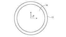
- FIG. Itis a top view of the dial carrying a touchpad.
- 3is a diagram illustrating a configuration of an operation information output unit of the operation input device according to Embodiment 1.
- FIG.It is a figure which shows the example of the hardware constitutions of an operation information output part. It is a figure which shows the example of the hardware constitutions of an operation information output part.
- FIG. 1It is a flowchart which shows operation
- FIG. 2It is a figure which shows the structure of the operation information output part of the operation input device which concerns on Embodiment 3.
- FIG. 2It is a figure which shows the structure of the operation information output part of the operation input device which concerns on Embodiment 4.
- FIG. 1is a diagram illustrating a configuration of an operation input device 10 according to the first embodiment.
- the casing 11 of the operation input device 10is indicated by a broken line.
- An opening 11ais provided on the top plate of the housing 11, and a lever 12 that is a movable operation unit (an operation unit that is operated by a user) projects from the opening 11a.
- the lever 12is provided with a dial 13 (knob) which is a movable operation portion at the top of the head.
- a touch pad 14is provided on the upper surface of the dial 13.
- the touch pad 14is a touch sensor that outputs a signal indicating coordinates (touch coordinates) corresponding to a position touched by the user.
- the lever 12is configured to be able to be pushed downward, and the entire lever 12 functions as a push switch as a movable operation unit.
- the usercan input various operations by tilting the lever 12, turning the dial 13, pressing the lever 12, or touching the touch pad 14.
- the dial 13is fixed to the lever 12 and the touch pad 14 is fixed to the dial 13. Therefore, when the user turns the dial 13, the entire lever 12 is rotated, and the touch pad 14 is also rotated with it.
- An operation(including a rotation operation) input by moving a movable operation unit such as the lever 12 or the dial 13 is referred to as a “displacement operation”.
- an operation that is performed by touching the touch pad 14is referred to as a “touch operation”.
- a support member 11 b that supports the lever operation detection unit 16is provided on the lower surface of the top plate of the housing 11.
- the support member 11bis provided with a spring member 15 that generates an appropriate reaction force when the user moves the lever 12 (not shown, but the spring member 15 is provided on each of the two support members 11b. Provided).
- the lever operation detection unit 16detects a movable operation (direction designation operation) performed by tilting the lever 12.
- the lever operation detection unit 16includes a groove that restricts the movable direction of the lever 12 in four directions, front, rear, left, and right, and four switches that detect the direction of displacement in the operation of the lever 12. That is, the lever operation detection unit 16 includes a front switch 16a that outputs a signal when the lever 12 is moved forward, a rear switch 16b that outputs a signal when the lever 12 is moved rearward, and a lever.
- a left switch 16c that outputs a signal when the lever 12 is moved leftward and a right switch 16d that outputs a signal when the lever 12 is moved rightwardare provided.
- the movable direction of the lever 12is four directions. However, for example, eight or sixteen directions may be designated, or an analog type in which all directions are movable directions may be used.
- a base 11 c that supports the dial rotation detection unit 17 and the brake mechanism 19 and a lever press detection unit 18are provided on the bottom plate of the housing 11.
- the dial rotation detection unit 17detects a movable operation (rotation operation) performed by rotating the dial 13.
- the dial rotation detector 17detects the rotation of the dial 13, that is, the rotation of the shaft of the lever 12, and outputs a signal corresponding to the rotation amount and the rotation direction (clockwise / counterclockwise).
- the lever pressing detection unit 18detects a movable operation (pressing operation) performed by pressing the lever 12.
- the lever pressing detection unit 18is a switch that detects pressing of the lever 12 (displacement in the downward direction), and outputs a signal when the lever 12 is pressed.
- the brake mechanism 19suppresses the movement of the lever 12 and the dial 13 which are movable operation parts while the user's touch operation is performed on the touch pad 14 so that they do not move easily. Ideally, the brake mechanism 19 should be able to completely fix the lever 12 and the dial 13.
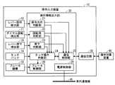
- the operation input device 10includes an operation information output unit 20 that outputs information (operation information) indicating the content of the operation input by the user, and an operation information output unit as illustrated in FIG. 3. And a communication circuit 30 that transmits the operation information output by 20 to a device 40 (operation target device) to be operated.
- the touch pad 14, the lever operation detection unit 16, the dial rotation detection unit 17, the lever press detection unit 18, and the brake mechanism 19 shown in FIG. 3correspond to those shown in FIG.
- the operation target device 40operates according to operation information transmitted from the operation input device 10, that is, information indicating the content of the user's operation. Therefore, the user can operate the operation target device 40 using the operation input device 10.
- operation information transmitted from the operation input device 10that is, information indicating the content of the user's operation. Therefore, the user can operate the operation target device 40 using the operation input device 10.
- a target operation apparatus 40a car navigation apparatus, a vehicle-mounted display audio system, etc. can be considered.
- the operation information output unit 20includes an operation direction determination unit 21, a rotation angle determination unit 22, a press determination unit 23, a touch operation determination unit 24, a communication control unit 25, and a brake control unit 26.
- the operation direction determination unit 21moves the lever 12 in the direction ( Operation information indicating the operation direction is generated.
- the rotation angle determination unit 22Based on the output signal of the dial rotation detection unit 17, the rotation angle determination unit 22 generates operation information indicating the rotation angle ( ⁇ shown in FIG. 2) of the dial 13 and the rotation direction thereof.
- the press determination unit 23generates operation information indicating whether the lever 12 is pressed as a push switch based on the output signal of the lever press detection unit 18.
- the touch operation determination unit 24analyzes the position (touch coordinates) of the user's touch operation and its movement (trajectory) based on the output signal of the touch pad 14, and generates operation information indicating the content of the touch operation.
- the contents of the touch operationinclude, for example, “tap” with one touch position, “swipe”, “drag”, “flick” with a change in touch position, “pinch” with multiple touch positions, and “rotate” "and so on.
- the touch operation determination unit 24determines the current orientation of the touch pad 14 from the operation information of the dial 13 output from the rotation angle determination unit 22 and corrects the touch coordinates according to the orientation.
- the communication control unit 25transmits various types of operation information output by the operation direction determination unit 21, the rotation angle determination unit 22, the press determination unit 23, and the touch operation determination unit 24 to the operation target device 40 using the communication circuit 30. .
- the brake control unit 26monitors whether or not an operation (touch operation) of the touch pad 14 is detected in the touch operation determination unit 24, and operates the brake mechanism 19 while the touch operation is detected to move the operation. The movements of the lever 12 and the dial 13 are suppressed.
- FIG. 4 and 5are diagrams showing examples of the hardware configuration of the operation information output unit 20, respectively.
- the processing circuit 50includes an operation direction determination unit 21 that generates operation information of the lever 12, a rotation angle determination unit 22 that generates operation information of the dial 13, and a press determination unit 23 that generates operation information of the lever 12.
- the touch operation determination unit 24that generates operation information of the touch pad 14, the communication control unit 25 that transmits the above operation information using the communication circuit 30, and the operation of the touch pad 14 are detected by the touch operation determination unit 24.
- the brake control unit 26While being operated, the brake control unit 26 is provided to operate the brake mechanism 19 and suppress the movement of the lever 12 and the dial 13.
- Dedicated hardwaremay be applied to the processing circuit 50, or a processor (Central processing unit, central processing unit, processing unit, arithmetic unit, microprocessor, microcomputer, digital, which executes a program stored in the memory Signal Processor) may be applied.
- a processorCentral processing unit, central processing unit, processing unit, arithmetic unit, microprocessor, microcomputer, digital, which executes a program stored in the memory Signal Processor
- the processing circuit 50When the processing circuit 50 is dedicated hardware, the processing circuit 50 corresponds to, for example, a single circuit, a composite circuit, a programmed processor, a processor programmed in parallel, an ASIC, an FPGA, or a combination thereof. To do.
- Each function of each element of the operation information output unit 20may be realized by a plurality of processing circuits 50, or these functions may be realized by a single processing circuit 50.
- FIG. 5shows a hardware configuration of the operation information output unit 20 when the processing circuit 50 is configured using a processor.
- the function of each element of the operation information output unit 20is realized by a combination of software and the like (software, firmware, or software and firmware).
- Software or the likeis described as a program and stored in the memory 52.
- the processor 51 as the processing circuit 50implements the functions of the respective units by reading out and executing the program stored in the memory 52. That is, the operation information output unit 20, when executed by the processing circuit 50, generates the operation information of the lever 12, generates the operation information of the dial 13, and generates the operation information of the lever 12.
- the memory 52is a non-volatile memory such as RAM (Random Access Memory), ROM (Read Only Memory), flash memory, EPROM (Erasable Programmable Read Only Memory), EEPROM (Electrically Erasable Programmable Read Only Memory), etc. Or a volatile semiconductor memory, HDD (Hard Disk
- RAMRandom Access Memory
- ROMRead Only Memory
- EPROMErasable Programmable Read Only Memory
- EEPROMElectrically Erasable Programmable Read Only Memory
- HDDHard Disk
- a magnetic diska flexible disk
- the present inventionis not limited to this, and a configuration may be adopted in which some elements of the operation information output unit 20 are realized by dedicated hardware and another part is realized by software or the like.
- the functions of some elementsare realized by the processing circuit 50 as dedicated hardware, and the processing circuit 50 as the processor 51 reads a program stored in the memory 52 for the other some elements.
- the functioncan be realized by executing.
- the processing circuit 50can realize the above-described functions by hardware, software, or the like, or a combination thereof.
- FIG. 6is a flowchart showing the operation of the operation direction determination unit 21.
- the operation direction determination unit 21confirms whether or not the operation of the lever 12 (which indicates a direction designation operation and does not include a pressing operation) has been performed (step S101).
- the operation direction determination unit 21stands by while the lever 12 is not operated (NO in step S101), and performs the following process when the lever 12 is operated (YES in step S101).
- the operation direction determination unit 21confirms whether or not the displacement direction (operation direction) of the lever 12 by the operation is forward (step S102). If the operation direction is forward (YES in step S102), “front” operation information is output (step S103). If the operation direction is not forward (NO in step S102), it is confirmed whether the operation direction is backward (step S104). If the operation direction is backward (YES in step S104), “rear” operation information is output (step S105). If the operation direction is not backward (NO in step S104), it is confirmed whether the operation direction is leftward (step S106). If the operation direction is to the left (YES in step S106), “left” operation information is output (step S107). If the operation direction is not left (NO in step S106), “right” operation information is output (step S108). Thereafter, the process returns to step S101.
- FIG. 7is a flowchart showing the operation of the rotation angle determination unit 22.
- the rotation angle determination unit 22checks whether or not the operation (rotation operation) of the dial 13 has been performed based on the output signal of the dial rotation detection unit 17 (step S201).
- the rotation angle determination unit 22stands by while the dial 13 is not operated (NO in step S201).
- the dial 13is operated (YES in step S201)
- the following processingis performed.
- step S202when the dial 13 is operated, the rotation angle determination unit 22 calculates the rotation angle ⁇ of the dial 13 by the operation (step S202).
- step S203If the rotation of the dial 13 is counterclockwise (YES in step S203), operation information obtained by adding “left rotation” information to the rotation angle ⁇ is output (step S204). If the rotation of the dial 13 is not counterclockwise (NO in step S203), the operation information in which the information of “right rotation” is added to the rotation angle ⁇ is output (step S205). Then, it returns to step S201.
- FIG. 8is a flowchart showing the operation of the press determination unit 23.
- the pressing determination unit 23checks whether or not the lever 12 is pressed (pressing operation) based on the output signal of the lever pressing detection unit 18 (step S301).
- the press determination unit 23waits while the lever 12 is not pressed (NO in step S301), and outputs the operation information of “press” when the lever 12 is pressed (YES in step S301) (step S302). . Then, it returns to step S301.
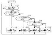
- FIG. 9is a flowchart showing operations of the touch operation determination unit 24 and the brake control unit 26.
- the touch operation determination unit 24monitors the operations of the operation direction determination unit 21, the rotation angle determination unit 22, and the press determination unit 23 to determine whether the lever 12 or the dial 13 that is a movable operation unit is being operated. Confirmation (step S401). Specifically, whether the operation of the lever 12 (direction designation operation) is detected in the operation direction determination unit 21, whether the operation of the dial 13 (rotation operation) is detected in the rotation angle determination unit 22, or the press determination unit 23. It is confirmed whether or not the pressing of the lever 12 (pressing operation) is detected (step S401).
- Touch operation determination unit 24stands by while either lever 12 or dial 13 is operated (YES in step S401). That is, the touch operation performed on the touch pad 14 while the lever 12 or the dial 13 is operated is ignored (invalidated).
- the touch operation input to the touch pad 14 during the operation of the lever 12 or the dial 13is highly likely to be erroneous due to the user touching the touch pad 14 by mistake. Is prevented.
- the touch operation determination unit 24performs the operation (touch operation) of the touch pad 14 based on the output signal of the touch pad 14. It is confirmed whether it has been interrupted (step S402). If the touch pad 14 has not been operated (NO in step S402), the process returns to step S401. If the touch pad 14 has been operated (YES in step S402), the following processing is performed.
- the brake control unit 26operates the brake mechanism 19 to suppress the movement of the lever 12 and the dial 13 (step S403). Thereby, the position fluctuation
- the touch operation determination unit 24analyzes the output signal of the touch pad 14 to determine the content of the touch operation (step S404), and outputs operation information indicating the content of the touch operation (step S405).
- the processes in steps S404 and S405are continuously performed until the touch operation is completed (step S406). Thereby, it is possible to deal with touch operations using a touch coordinate locus such as “drag” and “pinch”.
- a method for determining the end of the touch operationfor example, it can be determined that the touch operation has ended when the touch coordinates are no longer detected or when the touch coordinates have not moved for a certain period of time.
- the touch operation determination unit 24stops the operation of the brake mechanism 19 and opens the lever 12 and the dial 13 (step S407). Then, the process returns to step S401.
- the brake mechanism 19suppresses the movement of the lever 12 and the dial 13 while the touch pad 14 is operated by the user.
- the position of the touch pad 14can be stabilized, and erroneous operation of the touch pad 14 can be prevented.
- the touch operation determination unit 24invalidates the operation of the touch pad 14 while the lever 12 or the dial 13 is being operated, the user accidentally touches the touch pad 14 during the operation of the lever 12 and the dial 13. Can prevent misoperation.
- the brake control unit 26causes the brake mechanism 19 after the operation of the touch pad 14 is detected, but the operation of the touch pad 14 is predicted from the operation state of the operation target device 40, and
- the dial rotation detection unit 17may be operated before the touch pad 14 is operated. By fixing the position of the touch pad 14 before the touch operation is performed, a more stable touch operation can be performed. For example, when the operation target device 40 displays an input screen (for example, a handwritten character input screen) that accepts only a touch operation, it can be predicted that the touch pad 14 will be operated thereafter.
- the brake mechanism 19can be realized by a mechanism that tightens the shaft of the lever 12 from the outside with a brake pad, for example, a drum brake of an automobile.
- the brake padis retracted to a position that does not hinder the movement of the lever 12 when the brake mechanism 19 is off.
- the brake mechanism 19may be a caliper brake type including a brake disk 19a provided on the lever 12 and brake pads 19b and 19c sandwiching the brake disk 19a from above and below.
- the brake pads 19b and 19cretract to a position where they do not come into contact with the brake disc 19a even if the lever 12 moves.
- the brake pads 19b and 19csandwich the brake disc 19a to suppress the movement of the lever 12 and the dial 13.
- the presence of the lower brake pad 19chas an advantage that the depression of the lever 12 can be reliably prevented.
- FIG. 11is a diagram illustrating a configuration of the operation information output unit 20 in the operation input device 10 according to the second embodiment.
- the operation information output unit 20is obtained by adding a timer 27 for counting time to the configuration of the first embodiment.
- the operation direction determination unit 21, the rotation angle determination unit 22, and the press determination unit 23 of the operation information output unit 20have disclosed the operation of the lever 12 or the dial 13 based on the count of the timer 27. Only when the time exceeds a predetermined threshold, it is determined that the lever 12 or the dial 13 has been operated.
- step S101 in FIG. 6the operation direction determination unit 21 continues for 50 msec or longer from the switch of the lever operation detection unit 16 (any one of the front switch 16a, the rear switch 16b, the left switch 16c, and the right switch 16d).
- the rotation angle determination unit 22determines that the dial 13 has been operated (YES in step S201) when a signal is continuously received from the dial rotation detection unit 17 for 50 msec or longer in step S201 of FIG.
- the press determination unit 23determines that the lever 12 is pressed (YES in step S301) when a signal is continuously received from the lever press detection unit 18 for 50 msec or longer in step S301 in FIG.
- threshold value50 msec
- operation direction determination unit 21, the rotation angle determination unit 22, and the press determination unit 23may have different threshold values.
- the timer 27may be used for purposes other than determination of erroneous operation.
- the pressing determination unit 23may measure the length of time that the signal is output from the lever pressing detection unit 18 to distinguish between the normal pressing operation of the lever 12 and the long pressing operation.
- FIG. 12is a diagram illustrating a configuration of the operation information output unit 20 in the operation input device 10 according to the third embodiment.
- the operation information output unit 20is obtained by adding a reference information storage unit 28 to the configuration of the first embodiment.
- the reference information storage unit 28stores information on an operation pattern (reference pattern) that is a material for determining the content of the touch operation.
- the touch operation determination unit 24can determine more complicated operation content by comparing the operation pattern obtained from the locus of the touch coordinates acquired from the touch pad 14 with the reference pattern. For example, by including a character pattern in the reference pattern, the operation input device 10 can recognize the character, and the user can input handwritten characters using the touch pad 14.
- FIG. 13is a diagram illustrating a configuration of the operation information output unit 20 in the operation input device 10 according to the fourth embodiment.
- the operation information output unit 20is obtained by adding a power control unit 29 to the configuration of the first embodiment.
- Embodiment 4it is assumed that the operation input device 10 is mounted on a vehicle.
- the power supply control unit 29is connected to the in-vehicle communication line 45 of the vehicle on which the operation input device 10 is mounted, and when a specific vehicle signal (signal indicating the state of the vehicle) is detected, Operates to switch on and off.
- the power supply control unit 29monitors the vehicle signal indicating the state of the ignition key of the vehicle, and turns on the power supply of the operation input device 10 when detecting a signal indicating that the ignition key is turned on (ignition ON signal).
- ignition ON signalWhen the signal indicating that the ignition key is turned off (ignition OFF signal) is detected, the power of the operation input device 10 is turned off.
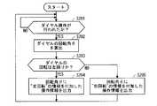
- FIG. 14is a flowchart showing the operation of the power control unit 29 in the present embodiment.
- the power supply control unit 29constantly monitors the vehicle signal on the in-vehicle communication line 45, and first waits for an ignition ON signal (step S501).
- the power control unit 29detects it (YES in step S501), and turns on the power of the operation information output unit 20 (step S502). ). Thereafter, the power supply control unit 29 waits for an ignition OFF signal (step S503).
- Step S503When the operation of the vehicle is stopped, if an ignition OFF signal is output to the in-vehicle communication line 45, the power control unit 29 detects it (YES in step S503), and turns off the power of the operation information output unit 20 (Step S504).
- the power on / off of the operation input device 10can be switched according to the operation state of the vehicle, it is possible to prevent the operation input device 10 from consuming electric power when the vehicle is stopped. , Increase convenience.
Landscapes
- Engineering & Computer Science (AREA)
- General Engineering & Computer Science (AREA)
- Theoretical Computer Science (AREA)
- Human Computer Interaction (AREA)
- Physics & Mathematics (AREA)
- General Physics & Mathematics (AREA)
- Chemical & Material Sciences (AREA)
- Combustion & Propulsion (AREA)
- Transportation (AREA)
- Mechanical Engineering (AREA)
- Position Input By Displaying (AREA)
- Input From Keyboards Or The Like (AREA)
Abstract
Description
Translated fromJapanese本発明は操作入力装置に関し、特に、可動操作部およびタッチパッドの両方を備える操作入力装置に関するものである。The present invention relates to an operation input device, and particularly to an operation input device including both a movable operation unit and a touch pad.
ユーザが動かして操作する可動操作部の上に、タッチパッドを設けた構造の操作入力装置が知られている(例えば、下記の特許文献1,2)。このような構造の操作入力装置は接地に必要な面積が小さくて済むため、例えば車両の運転席の周辺など、設置可能な位置および面積に制限ある場所への設置に有効である。An operation input device having a structure in which a touch pad is provided on a movable operation unit operated by a user is known (for example,
可動操作部上にタッチパッドを設けた構造の操作入力装置では、タッチパッドが可動操作部とともに動くため、タッチパッドの位置が不安定になる。例えばユーザがタッチパネルを操作する力で可動操作部が動いてしまうと、タッチパッドの位置も動いてしまい、その操作を正しく行うことができない。また、タッチパネルを操作する力で可動操作部が動くことで、可動操作部にユーザの意図しない操作(誤操作)が入力されるおそれもある。逆に、ユーザが可動操作部の操作時に誤ってタッチパッドに触れてしまうことで、タッチパッドの誤操作が生じることも懸念される。In an operation input device having a structure in which a touch pad is provided on the movable operation unit, the position of the touch pad becomes unstable because the touch pad moves together with the movable operation unit. For example, if the movable operation unit is moved by the force with which the user operates the touch panel, the position of the touch pad also moves, and the operation cannot be performed correctly. Moreover, there is a possibility that an operation (erroneous operation) unintended by the user may be input to the movable operation unit due to the movement of the movable operation unit with a force for operating the touch panel. On the contrary, there is a concern that an erroneous operation of the touch pad may occur if the user accidentally touches the touch pad when operating the movable operation unit.
本発明は以上のような課題を解決するためになされたものであり、可動操作部上にタッチパッドを有する操作入力装置における誤操作を防止することを目的とする。The present invention has been made to solve the above-described problems, and an object thereof is to prevent erroneous operation in an operation input device having a touch pad on a movable operation unit.
本発明の第1の態様に係る操作入力装置は、ユーザが動かして操作する可動操作部と、可動操作部上に配設され、ユーザがタッチ操作を入力するタッチパッドと、タッチパッドに対するタッチ操作が行われている間、可動操作部の動きを抑制するブレーキ機構と、を備えるものである。An operation input device according to a first aspect of the present invention includes a movable operation unit that is operated by a user, a touch pad that is disposed on the movable operation unit and that allows a user to input a touch operation, and a touch operation on the touch pad. And a brake mechanism that suppresses the movement of the movable operation unit.
本発明の第2の態様に係る操作入力装置は、ユーザが動かして操作する可動操作部と、可動操作部上に配設され、ユーザがタッチ操作を入力するタッチパッドと、可動操作部に対する変位操作が行われている間、タッチパッドのタッチ操作を無効にするタッチ操作判断部と、を備えるものである。An operation input device according to a second aspect of the present invention includes a movable operation unit that is moved and operated by a user, a touch pad that is disposed on the movable operation unit and that allows the user to input a touch operation, and displacement relative to the movable operation unit. A touch operation determination unit that disables the touch operation of the touch pad while the operation is being performed.
本発明によれば、タッチパッドの操作時に可動操作部が動くこと、または、可動操作部の操作時にタッチパッドの操作が検出されることが防止されるため、ユーザの意図しない操作(誤操作)を防止できる。According to the present invention, it is possible to prevent the movable operation unit from moving when the touch pad is operated or to detect the operation of the touch pad during the operation of the movable operation unit. Can be prevented.
本発明の目的、特徴、態様、および利点は、以下の詳細な説明と添付図面とによって、より明白となる。The objects, features, aspects and advantages of the present invention will become more apparent from the following detailed description and the accompanying drawings.
<実施の形態1>
図1は、実施の形態1に係る操作入力装置10の構成を示す図である。図1では、操作入力装置10の筐体11を破線で示している。筐体11の天板には開口部11aが設けられており、開口部11aからは、可動操作部(ユーザが動かして操作する操作部)であるレバー12が突出している。レバー12は、その頭頂部に、可動操作部であるダイヤル13(ノブ)が設けられている。図2のように、ダイヤル13の上面には、タッチパッド14が設けられている。タッチパッド14は、ユーザがタッチした位置に対応する座標(タッチ座標)を示す信号を出力するタッチセンサーである。また、レバー12は、下方向に押し込むことができるように構成されており、レバー12の全体が可動操作部としてのプッシュスイッチとして機能する。<
FIG. 1 is a diagram illustrating a configuration of an
ユーザは、レバー12を傾けたり、ダイヤル13を回したり、レバー12を押下したり、タッチパッド14にタッチしたりすることで、各種の操作を入力することができる。ここで、ダイヤル13はレバー12に固定されており、タッチパッド14はダイヤル13に固定されているものとする。よって、ユーザがダイヤル13を回すと、レバー12の全体が回転し、それとともにタッチパッド14も回転する。The user can input various operations by tilting the
レバー12、ダイヤル13といった可動操作部を動かして入力する操作(回転操作を含む)を「変位操作」という。一方、タッチパッド14をタッチして入力する操作を「タッチ操作」という。An operation (including a rotation operation) input by moving a movable operation unit such as the
筐体11の天板の下面には、レバー操作検出部16を支持する支持部材11bが設けられている。また、支持部材11bには、ユーザがレバー12を動かすときに適度の反力を発生させるバネ部材15が設けられている(図示は省略するが、バネ部材15は2つの支持部材11bのそれぞれに設けられている)。A
レバー操作検出部16は、レバー12を傾けることで行われる可動操作(方向指定操作)を検出する。レバー操作検出部16は、レバー12の可動方向を前後左右の4方向に制限する溝と、レバー12の操作における変位の方向を検出する4つのスイッチを備えている。すなわち、レバー操作検出部16は、上記溝の内側に、レバー12が前方へ動かされると信号を出力する前方スイッチ16aと、レバー12が後方へ動かされると信号を出力する後方スイッチ16bと、レバー12が左方へ動かされると信号を出力する左方スイッチ16cと、レバー12が右方へ動かされると信号を出力する右方スイッチ16dとを備えている。ここでは、レバー12の可動方向を4方向としたが、例えば8方向または16方向を指定できるようにしてもよいし、全方向を可動方向とするアナログ式にしてもよい。The lever
また、筐体11の底板上には、ダイヤル回転検出部17およびブレーキ機構19を支持する台座11cと、レバー押下検出部18とが設けられている。ダイヤル回転検出部17は、ダイヤル13を回転させることで行われる可動操作(回転操作)を検出する。ダイヤル回転検出部17は、ダイヤル13の回転、すなわちレバー12の軸の回転を検出し、その回転量と回転方向(右回り/左回り)に対応する信号を出力する。レバー押下検出部18は、レバー12を押下することで行われる可動操作(押下操作)を検出する。レバー押下検出部18は、レバー12の押下(下方向への変位)を検出するスイッチであり、レバー12が押下されると信号を出力する。Further, on the bottom plate of the
また、ブレーキ機構19は、タッチパッド14に対するユーザのタッチ操作が行われている間、可動操作部であるレバー12およびダイヤル13の動きを抑制して、それらが容易に動かないようにする。理想的には、ブレーキ機構19は、レバー12およびダイヤル13を完全に固定できるとよい。Further, the
図1での図示は省略したが、操作入力装置10は、図3のように、ユーザが入力した操作の内容を示す情報(操作情報)を出力する操作情報出力部20と、操作情報出力部20が出力した操作情報を、操作対象となる装置40(操作対象装置)へ送信する通信回路30とを備えている。図3に示されているタッチパッド14、レバー操作検出部16、ダイヤル回転検出部17、レバー押下検出部18、ブレーキ機構19は、それぞれ図1に示したものに対応している。Although not shown in FIG. 1, the
操作対象装置40は、操作入力装置10から送信された操作情報、すなわちユーザの操作の内容を示す情報に応じて動作する。よって、ユーザは、操作入力装置10を用いて操作対象装置40を操作することができる。操作対象装置40の種類に制限はないが、例えば、操作入力装置10が車両に搭載される場合、操作対象装置40としては、カーナビゲーション装置や、車載ディスプレイオーディオシステムなどが考えられる。The
図3のように、操作情報出力部20は、操作方向判断部21、回転角判断部22、押下判断部23、タッチ操作判断部24、通信制御部25およびブレーキ制御部26を備えている。As shown in FIG. 3, the operation
操作方向判断部21は、レバー操作検出部16の4つのスイッチ(前方スイッチ16a、後方スイッチ16b、左方スイッチ16cおよび右方スイッチ16d)の出力信号に基づいて、レバー12が動かされた方向(操作方向)を示す操作情報を生成する。回転角判断部22は、ダイヤル回転検出部17の出力信号に基づいて、ダイヤル13の回転角(図2に示すθ)およびその回転方向を示す操作情報を生成する。押下判断部23は、レバー押下検出部18の出力信号に基づいて、レバー12がプッシュスイッチとして押下されたかどうかを示す操作情報を生成する。Based on the output signals of the four switches (
タッチ操作判断部24は、タッチパッド14の出力信号に基づいて、ユーザのタッチ操作の位置(タッチ座標)およびその動き(軌跡)を解析して、タッチ操作の内容を示す操作情報を生成する。タッチ操作の内容としては、例えば、タッチ位置が1箇所である「タップ」、タッチ位置の変化を伴う「スワイプ」、「ドラッグ」、「フリック」、タッチ位置が複数となる「ピンチ」、「ローテート」などがある。なお、本実施の形態では、ダイヤル13が回転するとタッチパッド14の向きが変わるので、タッチパッド14の向きは一定しない。そのため、タッチ操作判断部24は、回転角判断部22が出力するダイヤル13の操作情報から、現在のタッチパッド14の向きを判断し、その向きに合わせてタッチ座標を補正している。The touch
通信制御部25は、操作方向判断部21、回転角判断部22、押下判断部23およびタッチ操作判断部24が出力する各種の操作情報を、通信回路30を用いて操作対象装置40へ送信する。The
ブレーキ制御部26は、タッチ操作判断部24においてタッチパッド14の操作(タッチ操作)が検出されているかどうかを監視し、タッチ操作が検出されている間、ブレーキ機構19を動作させて、可動操作部であるレバー12およびダイヤル13の動きを抑制する。The
図4および図5は、それぞれ操作情報出力部20のハードウェア構成の一例を示す図である。図1に示した操作情報出力部20の各要素(操作方向判断部21、回転角判断部22、押下判断部23、タッチ操作判断部24、通信制御部25およびブレーキ制御部26)は、例えば図4に示す処理回路50により実現される。すなわち、処理回路50は、レバー12の操作情報を生成する操作方向判断部21と、ダイヤル13の操作情報を生成する回転角判断部22と、レバー12の操作情報を生成する押下判断部23と、タッチパッド14の操作情報を生成するタッチ操作判断部24と、以上の各操作情報を通信回路30を用いて送信する通信制御部25と、タッチ操作判断部24によりタッチパッド14の操作が検出されている間、ブレーキ機構19を動作させてレバー12およびダイヤル13の動きを抑制するブレーキ制御部26とを備える。処理回路50には、専用のハードウェアが適用されてもよいし、メモリに格納されるプログラムを実行するプロセッサ(Central Processing Unit、中央処理装置、処理装置、演算装置、マイクロプロセッサ、マイクロコンピュータ、Digital Signal Processor)が適用されてもよい。4 and 5 are diagrams showing examples of the hardware configuration of the operation
処理回路50が専用のハードウェアである場合、処理回路50は、例えば、単一回路、複合回路、プログラム化したプロセッサ、並列プログラム化したプロセッサ、ASIC、FPGA、またはこれらを組み合わせたものなどが該当する。操作情報出力部20の各要素の機能のそれぞれは、複数の処理回路50で実現されてもよいし、それらの機能がまとめて一つの処理回路50で実現されてもよい。When the
図5は、処理回路50がプロセッサを用いて構成されている場合における操作情報出力部20のハードウェア構成を示している。この場合、操作情報出力部20の各要素の機能は、ソフトウェア等(ソフトウェア、ファームウェア、またはソフトウェアとファームウェア)との組み合わせにより実現される。ソフトウェア等はプログラムとして記述され、メモリ52に格納される。処理回路50としてのプロセッサ51は、メモリ52に記憶されたプログラムを読み出して実行することにより、各部の機能を実現する。すなわち、操作情報出力部20は、処理回路50により実行されるときに、レバー12の操作情報を生成するステップと、ダイヤル13の操作情報を生成するステップと、レバー12の操作情報を生成するステップと、タッチパッド14の操作情報を生成するステップと、以上の各操作情報を通信回路30を用いて送信するステップと、タッチパッド14の操作が検出されている間、レバー12およびダイヤル13の動きを抑制するステップと、が結果的に実行されることになるプログラムを格納するためのメモリ52を備える。換言すれば、このプログラムは、操作情報出力部20の各要素の動作の手順や方法をコンピュータに実行させるものであるともいえる。FIG. 5 shows a hardware configuration of the operation
ここで、メモリ52には、例えば、RAM(Random Access Memory)、ROM(Read Only Memory)、フラッシュメモリー、EPROM(Erasable Programmable Read Only Memory)、EEPROM(Electrically Erasable Programmable Read Only Memory)などの、不揮発性または揮発性の半導体メモリ、HDD(Hard Disk Drive)、磁気ディスク、フレキシブルディスク、光ディスク、コンパクトディスク、ミニディスク、DVD(Digital Versatile Disc)およびそのドライブ装置等が該当する。Here, the
以上、操作情報出力部20の各要素の機能が、ハードウェアおよびソフトウェア等のいずれか一方で実現される構成について説明した。しかしこれに限ったものではなく、操作情報出力部20の一部の要素を専用のハードウェアで実現し、別の一部の要素をソフトウェア等で実現する構成であってもよい。例えば、一部の要素については専用のハードウェアとしての処理回路50でその機能を実現し、他の一部の要素についてはプロセッサ51としての処理回路50がメモリ52に格納されたプログラムを読み出して実行することによってその機能を実現することが可能である。As described above, the configuration in which the function of each element of the operation
以上のように、処理回路50は、ハードウェア、ソフトウェア等、またはこれらの組み合わせによって、上述の各機能を実現することができる。As described above, the
以下、操作情報出力部20の各要素の動作について具体的に説明する。Hereinafter, the operation of each element of the operation
図6は、操作方向判断部21の動作を示すフローチャートである。操作方向判断部21は、レバー操作検出部16の出力信号に基づき、レバー12の操作(方向指定操作を指し、押下操作を含まない)が行われたか否かを確認する(ステップS101)。操作方向判断部21は、レバー12が操作されていない間は待機し(ステップS101でNO)、レバー12が操作されると(ステップS101でYES)、以下の処理を行う。FIG. 6 is a flowchart showing the operation of the operation direction determination unit 21. Based on the output signal of the lever
すなわち、レバー12が操作されると、操作方向判断部21は、その操作によるレバー12の変位方向(操作方向)が前方かどうかを確認する(ステップS102)。操作方向が前方であれば(ステップS102でYES)、“前方”の操作情報を出力する(ステップS103)。操作方向が前方でなければ(ステップS102でNO)、操作方向が後方かどうかを確認する(ステップS104)。操作方向が後方であれば(ステップS104でYES)、“後方”の操作情報を出力する(ステップS105)。操作方向が後方でなければ(ステップS104でNO)、操作方向が左方かどうかを確認する(ステップS106)。操作方向が左方であれば(ステップS106でYES)、“左方”の操作情報を出力する(ステップS107)。操作方向が左方でなければ(ステップS106でNO)、“右方”の操作情報を出力する(ステップS108)。その後、ステップS101へ戻る。That is, when the
図7は、回転角判断部22の動作を示すフローチャートである。回転角判断部22は、ダイヤル回転検出部17の出力信号に基づき、ダイヤル13の操作(回転操作)が行われたか否かを確認する(ステップS201)。回転角判断部22は、ダイヤル13の操作が行われていない間は待機し(ステップS201でNO)、ダイヤル13の操作が行われると(ステップS201でYES)、以下の処理を行う。FIG. 7 is a flowchart showing the operation of the rotation
すなわち、ダイヤル13が操作されると、回転角判断部22は、その操作によるダイヤル13の回転角θを算出する(ステップS202)。次に、回転角判断部22は、ダイヤル13の回転が左回りかどうかを確認する(ステップS203)。ダイヤル13の回転が左回りであれば(ステップS203でYES)、回転角θに“左回転”の情報を付加した操作情報を出力する(ステップS204)。ダイヤル13の回転が左回りでなければ(ステップS203でNO)、回転角θに“右回転”の情報を付加した操作情報を出力する(ステップS205)。その後、ステップS201へ戻る。That is, when the
図8は、押下判断部23の動作を示すフローチャートである。押下判断部23は、レバー押下検出部18の出力信号に基づき、レバー12の押下(押下操作)が行われたかどうかを確認する(ステップS301)。押下判断部23は、レバー12が押下されていない間は待機し(ステップS301でNO)、レバー12が押下されると(ステップS301でYES)“押下”の操作情報を出力する(ステップS302)。その後、ステップS301へ戻る。FIG. 8 is a flowchart showing the operation of the
図9は、タッチ操作判断部24およびブレーキ制御部26の動作を示すフローチャートである。タッチ操作判断部24は、操作方向判断部21、回転角判断部22および押下判断部23の動作を監視して、可動操作部であるレバー12またはダイヤル13の操作が行われているか否かを確認する(ステップS401)。具体的には、操作方向判断部21においてレバー12の操作(方向指定操作)が検出されているか、回転角判断部22においてダイヤル13の操作(回転操作)が検出されているか、押下判断部23によってレバー12の押下(押下操作)が検出されているかを確認する(ステップS401)。FIG. 9 is a flowchart showing operations of the touch
タッチ操作判断部24は、レバー12およびダイヤル13のいずれかが操作されている間は待機する(ステップS401でYES)。すなわち、レバー12またはダイヤル13が操作されている間にタッチパッド14に対して行われたタッチ操作は無視(無効化)される。レバー12またはダイヤル13の操作中にタッチパッド14へ入力されたタッチ操作は、ユーザが誤ってタッチパッド14に触れたことによる誤操作の可能性が高いため、ステップS401の処理により、その種の誤操作が防止される。Touch
タッチ操作判断部24は、レバー12およびダイヤル13のいずれもが操作されていないときは(ステップS401でNO)、タッチパッド14の出力信号に基づいて、タッチパッド14の操作(タッチ操作)が行われているかどうか確認する(ステップS402)。タッチパッド14が操作されていなければ(ステップS402でNO)、ステップS401へ戻るが、タッチパッド14が操作されていれば(ステップS402でYES)、以下の処理が行われる。When neither the
まず、ブレーキ制御部26が、ブレーキ機構19を動作させて、レバー12およびダイヤル13の動きを抑制する(ステップS403)。それにより、タッチパッド14の位置変動が抑制され、ユーザは安定してタッチ操作を行えるようになる。タッチ操作判断部24は、タッチパッド14の出力信号を解析してタッチ操作の内容を判断し(ステップS404)、タッチ操作の内容を示す操作情報を出力する(ステップS405)。ステップS404,S405の処理は、タッチ操作が終了するまで連続して行われる(ステップS406)。それにより、「ドラッグ」や「ピンチ」など、タッチ座標の軌跡を利用するタッチ操作にも対応できる。なお、タッチ操作の終了の判断手法としては、例えば、タッチ座標が検出されなくなったときや、タッチ座標が一定時間以上動かなかったときに、タッチ操作が終了したと判断することができる。First, the
ユーザによるタッチパッド14の操作が終了すると、タッチ操作判断部24がブレーキ機構19の動作を停止させ、レバー12およびダイヤル13を開放する(ステップS407)。そしてステップS401へ戻る。When the operation of the
以上のように、本実施の形態に係る操作入力装置10によれば、ユーザによりタッチパッド14が操作されている間、ブレーキ機構19がレバー12およびダイヤル13の動きを抑制するため、タッチパッド14の位置が安定し、タッチパッド14の誤操作を防止できる。また、レバー12またはダイヤル13が操作されている間、タッチ操作判断部24がタッチパッド14の操作を無効化するため、レバー12およびダイヤル13の操作中にユーザが誤ってタッチパッド14に触れることによる誤操作を防止できる。As described above, according to the
なお、本実施の形態では、ブレーキ制御部26は、タッチパッド14の操作が検出された後にブレーキ機構19させているが、操作対象装置40の動作状況からタッチパッド14の操作を予測して、タッチパッド14が操作される前からダイヤル回転検出部17を動作させてもよい。タッチ操作が行われる前からタッチパッド14の位置を固定することによって、より安定したタッチ操作が可能になる。例えば、操作対象装置40がタッチ操作のみを受け付ける入力画面(例えば手書き文字入力画面)を表示させたときは、その後にタッチパッド14が操作されることを予測できる。In the present embodiment, the
次に、ブレーキ機構19の構成例を説明する。ブレーキ機構19は、例えば、自動車のドラムブレーキのように、ブレーキパッドでレバー12の軸を外側から締める機構にて実現できる。ブレーキパッドは、ブレーキ機構19がオフのときに、レバー12の動きを妨げない位置にまで待避するようにする。Next, a configuration example of the
また、図10のように、ブレーキ機構19は、レバー12に設けられたブレーキディスク19aと、それを上下から挟むブレーキパッド19b,19cとから構成されるキャリパブレーキタイプにしてもよい。ブレーキ機構19がオフのとき、ブレーキパッド19b,19cは、レバー12が動いてもブレーキディスク19aに接触しない位置にまで待避する。また、ブレーキ機構19がオンのときは、ブレーキパッド19b,19cがブレーキディスク19aを挟むことでレバー12およびダイヤル13の動きを抑制する。特に、下側のブレーキパッド19cの存在により、レバー12の押下を確実に抑止できるという利点がある。As shown in FIG. 10, the
<実施の形態2>
図11は、実施の形態2に係る操作入力装置10における操作情報出力部20の構成を示す図である。当該操作情報出力部20は、実施の形態1の構成に対し、時間をカウントするタイマー27を追加したものとなっている。<Embodiment 2>
FIG. 11 is a diagram illustrating a configuration of the operation
実施の形態2では、操作情報出力部20の操作方向判断部21、回転角判断部22および押下判断部23は、タイマー27のカウントに基づいて、レバー12またはダイヤル13の操作が開示されてからの時間を測定し、その時間が予め定められた閾値を超えたときに限り、レバー12またはダイヤル13が操作されたものと判断する。In the second embodiment, the operation direction determination unit 21, the rotation
例えば、操作方向判断部21は、図6のステップS101において、レバー操作検出部16のスイッチ(前方スイッチ16a、後方スイッチ16b、左方スイッチ16cおよび右方スイッチ16dのいずれか)から50msec以上連続して信号を受けたときに、レバー12が操作された(ステップS101でYES)と判断する。また、回転角判断部22は、図7のステップS201において、ダイヤル回転検出部17から50msec以上連続して信号を受けたときに、ダイヤル13が操作された(ステップS201でYES)と判断する。同様に、押下判断部23は、図8のステップS301において、レバー押下検出部18から50msec以上連続して信号を受けたときに、レバー12が押下された(ステップS301でYES)と判断する。For example, in step S101 in FIG. 6, the operation direction determination unit 21 continues for 50 msec or longer from the switch of the lever operation detection unit 16 (any one of the
ごく短い時間の操作入力は、誤操作によるものである可能性が高いため、一定時間以上の操作入力だけを受け付けることで、誤操作を防止できる効果が得られる。また、ノイズの影響による操作入力装置10の誤動作も防止できる。Since the operation input for a very short time is likely to be due to an erroneous operation, it is possible to prevent the erroneous operation by accepting only the operation input for a certain time or more. Further, malfunction of the
なお、上記の閾値(50msec)は一例に過ぎず、任意の値でよい。また、操作方向判断部21、回転角判断部22および押下判断部23が、それぞれ異なる閾値を有していてもよい。Note that the above threshold value (50 msec) is merely an example and may be an arbitrary value. Further, the operation direction determination unit 21, the rotation
タイマー27は、誤操作の判定以外の用途に用いてもよい。例えば、押下判断部23において、レバー押下検出部18から信号が出力された時間の長さを測定し、レバー12の通常の押下操作と、長押し操作とを区別してもよい。The
<実施の形態3>
図12は、実施の形態3に係る操作入力装置10における操作情報出力部20の構成を示す図である。当該操作情報出力部20は、実施の形態1の構成に対し、リファレンス情報記憶部28を追加したものとなっている。<Embodiment 3>
FIG. 12 is a diagram illustrating a configuration of the operation
リファレンス情報記憶部28には、タッチ操作の内容の判断材料となる操作パターン(リファレンスパターン)の情報が記憶されている。タッチ操作判断部24は、タッチパッド14から取得したタッチ座標の軌跡から得られる操作パターンと、リファレンスパターンとを比較することで、より複雑な操作内容を判断することができる。例えば、リファレンスパターンに文字パターンを含ませることで、操作入力装置10は文字を認識できるようになり、ユーザはタッチパッド14を用いて手書きの文字入力が可能になる。The reference
<実施の形態4>
図13は、実施の形態4に係る操作入力装置10における操作情報出力部20の構成を示す図である。当該操作情報出力部20は、実施の形態1の構成に対し、電源制御部29を追加したものとなっている。<Embodiment 4>
FIG. 13 is a diagram illustrating a configuration of the operation
実施の形態4では、操作入力装置10は車両に搭載されているものとする。電源制御部29は、操作入力装置10を搭載した車両の車内通信線45に接続しており、特定の車両信号(車両の状態を示す信号)を検出したときに、操作入力装置10の電源のオン、オフを切り替えるように動作する。ここでは、電源制御部29は、車両のイグニッションキーの状態を表す車両信号を監視し、イグニッションキーがオンされたことを示す信号(イグニッションON信号)を検出すると操作入力装置10の電源をオンし、イグニッションキーがオフされたことを示す信号(イグニッションOFF信号)を検出すると操作入力装置10の電源をオフにするものとする。In Embodiment 4, it is assumed that the
図14は、本実施の形態における電源制御部29の動作を示すフローチャートである。電源制御部29は、定常的に車内通信線45上の車両信号を監視しており、まず、イグニッションON信号を待つ(ステップS501)。車両が起動するとき、車内通信線45にイグニッションON信号が出力されると、電源制御部29がそれを検出し(ステップS501でYES)、操作情報出力部20の電源をオンにする(ステップS502)。その後、電源制御部29は、イグニッションOFF信号を待つ(ステップS503)。車両の動作が停止されるとき、車内通信線45にイグニッションOFF信号が出力されると、電源制御部29がそれを検出し(ステップS503でYES)、操作情報出力部20の電源をオフにする(ステップS504)。FIG. 14 is a flowchart showing the operation of the
本実施の形態によれば、操作入力装置10の電源のオン、オフを車両の動作状況に合わせて切り替えることができるため、車両の停止時に操作入力装置10で電力が消費されることを防止でき、利便性が高くなる。According to the present embodiment, since the power on / off of the
なお、本発明は、その発明の範囲内において、各実施の形態を自由に組み合わせたり、各実施の形態を適宜、変形、省略することが可能である。It should be noted that the present invention can be freely combined with each other within the scope of the invention, and each embodiment can be appropriately modified or omitted.
本発明は詳細に説明されたが、上記した説明は、すべての態様において、例示であって、この発明がそれに限定されるものではない。例示されていない無数の変形例が、この発明の範囲から外れることなく想定され得るものと解される。Although the present invention has been described in detail, the above description is illustrative in all aspects, and the present invention is not limited thereto. It is understood that countless variations that are not illustrated can be envisaged without departing from the scope of the present invention.
10 操作入力装置、11 筐体、11a 開口部、11b 支持部材、11c 台座、12 レバー、13 ダイヤル、14 タッチパッド、15 バネ部材、16 レバー操作検出部、16a 前方スイッチ、16b 後方スイッチ、16c 左方スイッチ、16d 右方スイッチ、17 ダイヤル回転検出部、18 レバー押下検出部、19 ブレーキ機構、19a ブレーキディスク、19b ブレーキパッド、19c ブレーキパッド、20 操作情報出力部、21 操作方向判断部、22 回転角判断部、23 押下判断部、24 タッチ操作判断部、25 通信制御部、26 ブレーキ制御部、27 タイマー、28 リファレンス情報記憶部、29 電源制御部、30 通信回路、40 操作対象装置、45 車内通信線、50 処理回路、51 プロセッサ、52 メモリ。10 operation input device, 11 housing, 11a opening, 11b support member, 11c pedestal, 12 lever, 13 dial, 14 touch pad, 15 spring member, 16 lever operation detection unit, 16a front switch, 16b rear switch, 16c left Switch, 16d right switch, 17 dial rotation detection unit, 18 lever press detection unit, 19 brake mechanism, 19a brake disc, 19b brake pad, 19c brake pad, 20 operation information output unit, 21 operation direction determination unit, 22 rotation Corner determination unit, 23 press determination unit, 24 touch operation determination unit, 25 communication control unit, 26 brake control unit, 27 timer, 28 reference information storage unit, 29 power supply control unit, 30 communication circuit, 40 operation target device, 45 in the
Claims (10)
Translated fromJapanese前記可動操作部(12,13)上に配設され、ユーザがタッチ操作を入力するタッチパッド(14)と、
前記タッチパッド(14)に対するタッチ操作が行われている間、前記可動操作部(12,13)の動きを抑制するブレーキ機構(19)と、
を備える操作入力装置。A movable operation unit (12, 13) that is operated by the user;
A touch pad (14) disposed on the movable operation unit (12, 13) for a user to input a touch operation;
A brake mechanism (19) that suppresses the movement of the movable operation portion (12, 13) while a touch operation is being performed on the touchpad (14);
An operation input device comprising:
請求項1に記載の操作入力装置。The movable operation unit is a dial (13).
The operation input device according to claim 1.
請求項1に記載の操作入力装置。The movable operation part is a lever (12).
The operation input device according to claim 1.
請求項1に記載の操作入力装置。The movable operation unit is a push switch (12).
The operation input device according to claim 1.
請求項1に記載の操作入力装置。The said movable operation part is a lever (12) which has a dial (13) carrying the said touchpad (14) in a top part, and functions also as a push switch by pressing down. Operation input device.
前記可動操作部(12,13)上に配設され、ユーザがタッチ操作を入力するタッチパッド(14)と、
前記可動操作部(12,13)に対する変位操作が行われている間、前記タッチパッド(14)のタッチ操作を無効にするタッチ操作判断部と、
を備える操作入力装置。A movable operation unit (12, 13) that is operated by the user;
A touch pad (14) disposed on the movable operation unit (12, 13) for a user to input a touch operation;
A touch operation determination unit that disables the touch operation of the touch pad (14) while a displacement operation is performed on the movable operation unit (12, 13);
An operation input device comprising:
請求項6に記載の操作入力装置。The movable operation unit is a dial (13).
The operation input device according to claim 6.
請求項6に記載の操作入力装置。The movable operation part is a lever (12).
The operation input device according to claim 6.
請求項6に記載の操作入力装置。The movable operation unit is a push switch (12).
The operation input device according to claim 6.
請求項6に記載の操作入力装置。The said movable operation part is a lever (12) which has a dial (13) carrying the said touchpad (14) in a top part, and functions also as a push switch by pressing down. Operation input device.
Priority Applications (5)
| Application Number | Priority Date | Filing Date | Title |
|---|---|---|---|
| PCT/JP2016/054500WO2017141364A1 (en) | 2016-02-17 | 2016-02-17 | Operation input device |
| CN201680080914.0ACN108700955B (en) | 2016-02-17 | 2016-02-17 | Operation input device |
| US16/062,790US10572037B2 (en) | 2016-02-17 | 2016-02-17 | Rotary dial with touch pad input surface and directional tilting operations |
| DE112016006446.2TDE112016006446T5 (en) | 2016-02-17 | 2016-02-17 | Operator input device |
| JP2017567869AJP6594461B2 (en) | 2016-02-17 | 2016-02-17 | Operation input device |
Applications Claiming Priority (1)
| Application Number | Priority Date | Filing Date | Title |
|---|---|---|---|
| PCT/JP2016/054500WO2017141364A1 (en) | 2016-02-17 | 2016-02-17 | Operation input device |
Publications (1)
| Publication Number | Publication Date |
|---|---|
| WO2017141364A1true WO2017141364A1 (en) | 2017-08-24 |
Family
ID=59625716
Family Applications (1)
| Application Number | Title | Priority Date | Filing Date |
|---|---|---|---|
| PCT/JP2016/054500CeasedWO2017141364A1 (en) | 2016-02-17 | 2016-02-17 | Operation input device |
Country Status (5)
| Country | Link |
|---|---|
| US (1) | US10572037B2 (en) |
| JP (1) | JP6594461B2 (en) |
| CN (1) | CN108700955B (en) |
| DE (1) | DE112016006446T5 (en) |
| WO (1) | WO2017141364A1 (en) |
Cited By (2)
| Publication number | Priority date | Publication date | Assignee | Title |
|---|---|---|---|---|
| WO2020255506A1 (en)* | 2019-06-17 | 2020-12-24 | アルプスアルパイン株式会社 | Input device |
| JP2023014218A (en)* | 2019-03-12 | 2023-01-26 | 株式会社ワコム | Touch pad and computer |
Families Citing this family (1)
| Publication number | Priority date | Publication date | Assignee | Title |
|---|---|---|---|---|
| JP2025035044A (en)* | 2023-08-31 | 2025-03-13 | アルプスアルパイン株式会社 | Input Devices |
Citations (5)
| Publication number | Priority date | Publication date | Assignee | Title |
|---|---|---|---|---|
| JP2008071165A (en)* | 2006-09-14 | 2008-03-27 | Canon Inc | Item indicating device and item indicating method |
| JP2013256186A (en)* | 2012-06-12 | 2013-12-26 | Toyota Auto Body Co Ltd | Control device |
| JP2015069382A (en)* | 2013-09-27 | 2015-04-13 | 本田技研工業株式会社 | Operating device |
| JP2015176286A (en)* | 2014-03-14 | 2015-10-05 | 株式会社デンソー | Device operation apparatus |
| WO2015170448A1 (en)* | 2014-05-09 | 2015-11-12 | 株式会社デンソー | Operation device |
Family Cites Families (10)
| Publication number | Priority date | Publication date | Assignee | Title |
|---|---|---|---|---|
| DE3836555A1 (en)* | 1988-10-27 | 1990-05-10 | Bayerische Motoren Werke Ag | MULTIFUNCTION CONTROL DEVICE |
| DE10120691A1 (en)* | 2001-04-27 | 2002-11-21 | Siemens Ag | Operating unit, in particular for operating a multimedia system in a motor vehicle |
| US20060181517A1 (en)* | 2005-02-11 | 2006-08-17 | Apple Computer, Inc. | Display actuator |
| DE10341016B4 (en) | 2003-09-03 | 2016-11-17 | Continental Automotive Gmbh | Operating element, in particular for a multimedia system of a motor vehicle |
| DE102004045885A1 (en)* | 2004-09-22 | 2006-03-23 | Volkswagen Ag | Operating element for a motor vehicle |
| JP4922901B2 (en)* | 2007-11-19 | 2012-04-25 | アルプス電気株式会社 | Input device |
| JP4771237B2 (en) | 2008-10-23 | 2011-09-14 | 株式会社デンソー | Vehicle control device |
| JP6007162B2 (en)* | 2013-10-01 | 2016-10-12 | 京楽産業.株式会社 | Game machine |
| JP6292617B2 (en)* | 2014-04-16 | 2018-03-14 | キャタピラー エス エー アール エル | Input control method for touch panel monitor for work machines |
| CN105194871B (en)* | 2015-09-14 | 2017-03-22 | 网易(杭州)网络有限公司 | Method for controlling game role |
- 2016
- 2016-02-17WOPCT/JP2016/054500patent/WO2017141364A1/ennot_activeCeased
- 2016-02-17JPJP2017567869Apatent/JP6594461B2/ennot_activeExpired - Fee Related
- 2016-02-17USUS16/062,790patent/US10572037B2/ennot_activeExpired - Fee Related
- 2016-02-17DEDE112016006446.2Tpatent/DE112016006446T5/ennot_activeCeased
- 2016-02-17CNCN201680080914.0Apatent/CN108700955B/ennot_activeExpired - Fee Related
Patent Citations (5)
| Publication number | Priority date | Publication date | Assignee | Title |
|---|---|---|---|---|
| JP2008071165A (en)* | 2006-09-14 | 2008-03-27 | Canon Inc | Item indicating device and item indicating method |
| JP2013256186A (en)* | 2012-06-12 | 2013-12-26 | Toyota Auto Body Co Ltd | Control device |
| JP2015069382A (en)* | 2013-09-27 | 2015-04-13 | 本田技研工業株式会社 | Operating device |
| JP2015176286A (en)* | 2014-03-14 | 2015-10-05 | 株式会社デンソー | Device operation apparatus |
| WO2015170448A1 (en)* | 2014-05-09 | 2015-11-12 | 株式会社デンソー | Operation device |
Cited By (7)
| Publication number | Priority date | Publication date | Assignee | Title |
|---|---|---|---|---|
| JP2023014218A (en)* | 2019-03-12 | 2023-01-26 | 株式会社ワコム | Touch pad and computer |
| JP7509857B2 (en) | 2019-03-12 | 2024-07-02 | 株式会社ワコム | Touchpad and Computer |
| JP2024111217A (en)* | 2019-03-12 | 2024-08-16 | 株式会社ワコム | Touchpad and Computer |
| JP7716538B2 (en) | 2019-03-12 | 2025-07-31 | 株式会社ワコム | Touchpad and Computer |
| WO2020255506A1 (en)* | 2019-06-17 | 2020-12-24 | アルプスアルパイン株式会社 | Input device |
| JPWO2020255506A1 (en)* | 2019-06-17 | 2020-12-24 | ||
| JP7266677B2 (en) | 2019-06-17 | 2023-04-28 | アルプスアルパイン株式会社 | input device |
Also Published As
| Publication number | Publication date |
|---|---|
| JPWO2017141364A1 (en) | 2018-05-24 |
| US20180373347A1 (en) | 2018-12-27 |
| US10572037B2 (en) | 2020-02-25 |
| DE112016006446T5 (en) | 2018-11-29 |
| JP6594461B2 (en) | 2019-10-23 |
| CN108700955A (en) | 2018-10-23 |
| CN108700955B (en) | 2021-04-20 |
Similar Documents
| Publication | Publication Date | Title |
|---|---|---|
| US11175775B2 (en) | Input device, touch panel control device, and touch panel control method | |
| KR20200103901A (en) | Gesture interface system for autonomous vehicle and operating method thereof | |
| JP6758408B2 (en) | Display device with touch panel | |
| JP6594461B2 (en) | Operation input device | |
| KR101773032B1 (en) | Multifunctional composite input device | |
| JP4924164B2 (en) | Touch input device | |
| WO2015170448A1 (en) | Operation device | |
| JP2007102749A (en) | Multi-function touch panel and control method | |
| JP2009289157A (en) | Display device, control method for display device and program for making computer realize the control method | |
| JP2018107618A5 (en) | ||
| US20230264570A1 (en) | Operating unit comprising a touch-sensitive operating area | |
| JP5147821B2 (en) | Input device | |
| CN107037877A (en) | Motor vehicles | |
| JP2011141796A (en) | Operation guide structure for planar input device | |
| JP2022112905A (en) | input device | |
| JP5723908B2 (en) | Input operation acceptance device | |
| JP2010257077A (en) | Operation input device | |
| JP7222960B2 (en) | touch panel device | |
| JP6851459B2 (en) | Touchpad operation detection device and touchpad operation detection method | |
| US11175782B2 (en) | Input control device and input control method | |
| JP2016218564A (en) | Tactile sense presentation device | |
| US11451228B2 (en) | Operating device for a motor vehicle, method for operating a motor vehicle with the aid of the operating device, control unit, and motor vehicle | |
| JP7332450B2 (en) | Switch device and operating device | |
| JP7473954B2 (en) | Touch Sensor Unit | |
| JP2016218820A (en) | Operation detection device |
Legal Events
| Date | Code | Title | Description |
|---|---|---|---|
| 121 | Ep: the epo has been informed by wipo that ep was designated in this application | Ref document number:16890506 Country of ref document:EP Kind code of ref document:A1 | |
| ENP | Entry into the national phase | Ref document number:2017567869 Country of ref document:JP Kind code of ref document:A | |
| 122 | Ep: pct application non-entry in european phase | Ref document number:16890506 Country of ref document:EP Kind code of ref document:A1 |