WO2017141358A1 - Flavor inhaler - Google Patents
Flavor inhalerDownload PDFInfo
- Publication number
- WO2017141358A1 WO2017141358A1PCT/JP2016/054487JP2016054487WWO2017141358A1WO 2017141358 A1WO2017141358 A1WO 2017141358A1JP 2016054487 WJP2016054487 WJP 2016054487WWO 2017141358 A1WO2017141358 A1WO 2017141358A1
- Authority
- WO
- WIPO (PCT)
- Prior art keywords
- generator
- unit
- battery
- power supplied
- generation
- Prior art date
- Legal status (The legal status is an assumption and is not a legal conclusion. Google has not performed a legal analysis and makes no representation as to the accuracy of the status listed.)
- Ceased
Links
Images


Classifications
- A—HUMAN NECESSITIES
- A24—TOBACCO; CIGARS; CIGARETTES; SIMULATED SMOKING DEVICES; SMOKERS' REQUISITES
- A24F—SMOKERS' REQUISITES; MATCH BOXES; SIMULATED SMOKING DEVICES
- A24F40/00—Electrically operated smoking devices; Component parts thereof; Manufacture thereof; Maintenance or testing thereof; Charging means specially adapted therefor
- A24F40/50—Control or monitoring
- A—HUMAN NECESSITIES
- A24—TOBACCO; CIGARS; CIGARETTES; SIMULATED SMOKING DEVICES; SMOKERS' REQUISITES
- A24F—SMOKERS' REQUISITES; MATCH BOXES; SIMULATED SMOKING DEVICES
- A24F40/00—Electrically operated smoking devices; Component parts thereof; Manufacture thereof; Maintenance or testing thereof; Charging means specially adapted therefor
- A24F40/30—Devices using two or more structurally separated inhalable precursors, e.g. using two liquid precursors in two cartridges
- A—HUMAN NECESSITIES
- A24—TOBACCO; CIGARS; CIGARETTES; SIMULATED SMOKING DEVICES; SMOKERS' REQUISITES
- A24D—CIGARS; CIGARETTES; TOBACCO SMOKE FILTERS; MOUTHPIECES FOR CIGARS OR CIGARETTES; MANUFACTURE OF TOBACCO SMOKE FILTERS OR MOUTHPIECES
- A24D1/00—Cigars; Cigarettes
- A24D1/002—Cigars; Cigarettes with additives, e.g. for flavouring
- A—HUMAN NECESSITIES
- A24—TOBACCO; CIGARS; CIGARETTES; SIMULATED SMOKING DEVICES; SMOKERS' REQUISITES
- A24F—SMOKERS' REQUISITES; MATCH BOXES; SIMULATED SMOKING DEVICES
- A24F40/00—Electrically operated smoking devices; Component parts thereof; Manufacture thereof; Maintenance or testing thereof; Charging means specially adapted therefor
- A24F40/10—Devices using liquid inhalable precursors
- A—HUMAN NECESSITIES
- A24—TOBACCO; CIGARS; CIGARETTES; SIMULATED SMOKING DEVICES; SMOKERS' REQUISITES
- A24F—SMOKERS' REQUISITES; MATCH BOXES; SIMULATED SMOKING DEVICES
- A24F40/00—Electrically operated smoking devices; Component parts thereof; Manufacture thereof; Maintenance or testing thereof; Charging means specially adapted therefor
- A24F40/40—Constructional details, e.g. connection of cartridges and battery parts
- A24F40/42—Cartridges or containers for inhalable precursors
- A—HUMAN NECESSITIES
- A24—TOBACCO; CIGARS; CIGARETTES; SIMULATED SMOKING DEVICES; SMOKERS' REQUISITES
- A24F—SMOKERS' REQUISITES; MATCH BOXES; SIMULATED SMOKING DEVICES
- A24F40/00—Electrically operated smoking devices; Component parts thereof; Manufacture thereof; Maintenance or testing thereof; Charging means specially adapted therefor
- A24F40/50—Control or monitoring
- A24F40/51—Arrangement of sensors
- A—HUMAN NECESSITIES
- A61—MEDICAL OR VETERINARY SCIENCE; HYGIENE
- A61M—DEVICES FOR INTRODUCING MEDIA INTO, OR ONTO, THE BODY; DEVICES FOR TRANSDUCING BODY MEDIA OR FOR TAKING MEDIA FROM THE BODY; DEVICES FOR PRODUCING OR ENDING SLEEP OR STUPOR
- A61M15/00—Inhalators
- A61M15/06—Inhaling appliances shaped like cigars, cigarettes or pipes
- H—ELECTRICITY
- H05—ELECTRIC TECHNIQUES NOT OTHERWISE PROVIDED FOR
- H05B—ELECTRIC HEATING; ELECTRIC LIGHT SOURCES NOT OTHERWISE PROVIDED FOR; CIRCUIT ARRANGEMENTS FOR ELECTRIC LIGHT SOURCES, IN GENERAL
- H05B3/00—Ohmic-resistance heating
- H05B3/40—Heating elements having the shape of rods or tubes
- H05B3/42—Heating elements having the shape of rods or tubes non-flexible
Definitions
- the present inventionrelates to a flavor inhaler having a plurality of generating parts that generate suction components from a suction component source by electric power supplied from a battery.
- the first featureis a battery that stores electric power, a first generator that generates a first suction component from a first suction component source by the power supplied from the battery, and a second that is generated by the power supplied from the battery.
- a second generatorthat generates a second suction component from a suction component source; and a controller that controls the amount of power supplied to the first generator and the second generator, the first generator and the The second generator is provided on an air flow path communicating from the inlet to the outlet, and the first generator and the second generator are electrically connected by parallel connection or series connection, and the battery Is expressed by V A , the reference voltage value of the battery is expressed by V C , and the correction term for the amount of power supplied to the first generator and the second generator is D 1.
- the control unitis represented by To calculate the D 1 based on the serial V A and the V C, and summarized in that controlling the amount of power on the basis of the D 1.
- the gist of the second featureis that, in the first feature, the second generator is provided on the downstream side of the first generator in the air flow path.
- the third featureis summarized in that in the first feature or the second feature, the first generator and the second generator are electrically connected in series.
- the fourth featureis that a battery for storing electric power, a first generator for generating a first suction component from a first suction component source by the power supplied from the battery, and a second by power supplied from the battery.
- a second generation unit that generates a second suction component from a suction component source, and the first generation unit and the second generation unitare provided on an air flow path that communicates from an inlet to an outlet.
- the generation unit and the second generation unitare electrically connected by parallel connection or series connection, and at least one of the first generation unit and the second generation unit extends in a coil shape along the air flow path.
- the gist of the present inventionis that it is constituted by a resistance heating element.
- a fifth featureis any one of the first feature to the fourth feature, comprising: a first unit having at least the first generator; and a second unit having at least the second generator.
- the gistis that one unit and the second unit are separate bodies.
- the sixth featureis summarized in that, in the fifth feature, the second unit is configured to be detachable from the first unit.
- a seventh featureis the fifth feature or the sixth feature, wherein the first generator and the second generator have a connection point or a conductive member when connecting the first unit and the second unit.
- the first generator and the second generatorare electrically connected without passing through the controller on the electrical circuit through the connection point or the conductive member.
- the gistis the fifth feature or the sixth feature, wherein the first generator and the second generator have a connection point or a conductive member when connecting the first unit and the second unit.
- the first generator and the second generatorare electrically connected without passing through the controller on the electrical circuit through the connection point or the conductive member.
- At least one of the first suction component source and the second suction component sourceis an aerosol source
- the first generator and The gist of the inventionis that at least one of the second generation units is an atomization unit that atomizes the aerosol source.
- the ninth featureis summarized as that, in the eighth feature, the atomizing section is configured by a resistance heating element.
- a tenth featureincludes a control unit that controls the amount of power supplied to the first generation unit and the second generation unit in the fourth feature, and an output voltage value of the battery is represented by VA .
- the reference voltage value of the batteryis represented by V C
- the correction term of the first generating unit and the amount of power supplied to said second generating portionis represented by D 1
- the control unitthe V to calculate the D 1 based on a and the V C, and summarized in that controlling the amount of power on the basis of the D 1.
- the twelfth featureis any one of the first feature to the third feature, the tenth feature, and the eleventh feature, wherein the control unit is at least one of the first generator and the second generator.
- the gistis to acquire the VA in a state where a voltage is applied to one side.
- a thirteenth featureis any one of the first feature to the third feature and the tenth feature to the twelfth feature, wherein the first generator and the second generator are configured by a resistance heating element.
- the control unitobtains the electrical resistance value of the first generation unit and the combined resistance value of the first generation unit and the second generation unit.
- a fourteenth featureis any one of the first feature to the thirteenth feature, wherein the first generator and the second generator are electrically connected by a series connection, and the first generator and the second generating unit is configured by a resistance heating element, the electrical resistance value of the first generating unit is represented by R 1, the electric resistance value of the second generation unit is represented by R 2, correction term amount of power supplied to the first generating portion is represented by D 2, the to calculate the D 2 on the basis of the R 1 and the R 2, the first generation on the basis of the D 2
- the gistis to include a control unit that controls the amount of power supplied to the unit.
- a sixteenth featureis any one of the first feature to the fifteenth feature, wherein the first generator is constituted by a resistance heating element, and the electric resistance value of the first generator or the first occurrence is generated.
- the gist of the present inventionis to provide an information source having identification information associated with the electrical resistance value of the unit.
- control unitprevents an amount of power supplied to the first generation unit from exceeding an upper limit threshold in one puff operation.
- the gistis to control the amount of power supplied to the first generator.
- FIG. 1is a diagram illustrating a flavor inhaler 10 according to an embodiment.
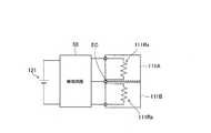
- FIG. 2is a diagram illustrating an atomization unit 111 according to the embodiment.
- FIG. 3is a diagram illustrating a block configuration of the flavor inhaler 10 according to the embodiment.
- FIG. 4is a diagram for explaining the relationship of linearity of L and E according to the embodiment.
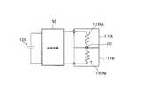
- FIG. 5is a diagram illustrating a circuit configuration of the generation unit 111R provided in each of the plurality of atomization units 111 according to the embodiment.
- FIG. 6is a diagram illustrating the atomization unit 111 according to the first modification.
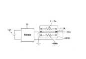
- FIG. 7is a diagram illustrating a circuit configuration of a generation unit 111R provided in each of the plurality of atomization units 111 according to the first modification.
- FIG. 8is a diagram illustrating a circuit configuration of the generator 111R provided in each of the plurality of atomizing units 111 according to the second modification.
- FIG. 9is a diagram illustrating a circuit configuration of the generator 111R provided in each of the plurality of atomizing units 111 according to the second modification.
- FIG. 10is a diagram illustrating a circuit configuration of a generator 111R provided in each of the plurality of atomizing units 111 according to the second modification.
- FIG. 11is a diagram illustrating a circuit configuration of the generator 111R provided in each of the plurality of atomizing units 111 according to the second modification.
- FIG. 12is a diagram illustrating an atomization unit 111 according to the third modification.
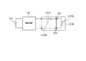
- FIG. 13is a diagram illustrating a circuit configuration of the generator 111R provided in each of the plurality of atomizing units 111 according to the modification example 6. As illustrated in FIG.
- a flavor inhalerincludes a battery that stores electric power, a first generation unit that generates a first suction component from a first suction component source by the power supplied from the battery, and the battery.
- a second generatorthat generates a second suction component from a second suction component source by the supplied power; and a controller that controls the amount of power supplied to the first generator and the second generator.
- the first generator and the second generatorare provided on an air flow path communicating from the inlet to the outlet, the output voltage value of the battery is represented by VA , and the reference voltage value of the battery is A correction term for the amount of power represented by V C and supplied to the first generation unit and the second generation unit is represented by D 1 , and the control unit is based on the V A and the V C D 1 is calculated and the D The power amount is controlled based on 1 .
- control unitcalculates D 1 based on V A and V C and controls the amount of power based on D 1 . Therefore, even if the output voltage value of the battery can vary depending on the number of generators connected and the configuration of each generator (especially the electrical resistance value), a desired amount of power is supplied to the first generator and the second generator. Can be supplied to.
- the flavor inhalerincludes a battery that stores electric power, a first generation unit that generates a first suction component from a first suction component source by the power supplied from the battery, and the battery.
- a second generation unitthat generates a second suction component from a second suction component source by the supplied power, and the first generation unit and the second generation unit are provided on an air flow path that communicates from the inlet to the outlet.
- the first generator and the second generatorare electrically connected by parallel connection or series connection, and at least one of the first generator and the second generator is the air flow It is comprised by the coil-shaped resistance heating element extended along a path.
- At least one of the first generator and the second generatoris configured by a coiled resistance heating element extending along the air flow path. Therefore, it is easy to dispose the conductive member for supplying power to the generator having the resistance heating element.
- FIG. 1is a diagram illustrating a flavor inhaler 10 according to an embodiment.
- FIG. 2is a diagram illustrating an atomization unit 111 according to the embodiment.
- the flavor inhaler 10is an instrument for sucking flavor components without combustion, and has a shape extending along a predetermined direction A that is a direction from the non-suction end to the suction end.
- the flavor suction device 10has a suction device body 100 and a mouthpiece unit 200.
- the suction unit main body 100constitutes the main body of the flavor suction unit 10 and has a shape to which the suction unit 200 can be connected.
- the suction unit main body 100includes a first main body unit 110 and a second main body unit 120.
- the aspirator body 100has a cylinder 100X, and the suction unit 200 is connected to the suction side end of the cylinder 100X.
- the first main body unit 110includes a first cylinder 110X that constitutes a part of the cylinder 100X.
- the first main body unit 110has a plurality of generators that generate suction components from suction component sources by power supplied from a battery 121 described later.
- the first main body unit 110includes a first atomizing unit 111 ⁇ / b> A and a second atomizing unit 111 ⁇ / b> B as the plurality of atomizing units 111 each having a plurality of generating units.
- first atomization unit 111A and the second atomization unit 111Bmay have the same configuration or may have different configurations. In the embodiment, the first atomization unit 111A and the second atomization unit 111B will be described as having the same configuration.
- the first atomizing unit 111A and the second atomizing unit 111Bare preferably separate units.
- the first atomizing unit 111A and the second atomizing unit 111Bmay be configured to be detachable from the cylinder 100X.
- the first atomizing unit 111A and the second atomizing unit 111Bmay be configured to be detachable from each other.
- each of the plurality of atomizing units 111includes a reservoir 111P, a wick 111Q, and a generation unit 111R as illustrated in FIG.
- the reservoir 111Pstores a suction component source.
- the reservoir 111Pis a porous body made of a material such as a resin web.
- the wick 111Qholds the suction component source stored in the reservoir 111P.
- the wick 111Qis made of glass fiber.
- the generator 111Rgenerates a suction component from a suction component source held by the wick 111Q.
- the generation unit 111Ris configured by, for example, a resistance heating element wound around the wick 111Q at a predetermined pitch.
- the resistance heating elementhas a coil shape extending from the inlet 120A so as to cross an air flow path communicating with an outlet 200A described later.
- the suction component sourceis a material for generating a suction component.
- the inhalation component sourceis an aerosol source for generating an aerosol as an inhalation component. Therefore, the generation unit 111R is an example of an atomization unit that atomizes a suction component source (aerosol source).
- the suction component sourceis, for example, a liquid (aerosol source) such as glycerin or propylene glycol.
- a liquidsuch as glycerin or propylene glycol.
- the suction component sourceis held by a porous body made of a material such as a resin web.
- the porous bodymay be made of a non-tobacco material or may be made of a tobacco material.
- the suction component sourcemay include a flavor source containing a flavor component. Or the suction component source does not need to contain the flavor source containing a flavor component.
- each of the plurality of atomizing units 111includes a cylindrical member 111X, an electrode 111E, a lead wire 111L, and an insulating member 111I in addition to the reservoir 111P, the wick 111Q, and the generator 111R. .
- the cylindrical member 111Xconstitutes an air flow path in one atomization unit 111.
- the reservoir 111P described aboveis disposed in parallel with the air flow path, and is partitioned from the air flow path by the cylindrical member 111X.
- the wick 111Q described abovepenetrates the cylindrical member 111X and crosses the air flow path.
- the generator 111R described aboveis disposed in the air flow path of the cylindrical member 111X.
- Electrode 111E provided in one atomizing unit 111, the electrode pairs provided on the downstream with respect to generator 111R in the electrode-to-111E 1 and the air flow pathis provided upstream with respect to generator 111R in the air flow path 111E 2 including.
- One electrode pair 111E 1 and the electrode pairis provided on the atomization unit 111 111E 2, each constituting a pair of electrodes (anode and cathode). It leads 111L, within one atomizing unit 111, the electrode pairs 111E 1 and electrode pair 111E 2 is a power line for electrically connecting. Also, the positive and negative electrodes constituting the electrode pair 111E 1 is electrically connected via leads 111L and generator 111R. The same applies to the respective electrodes constituting the electrode pair 111E 2.
- the insulating member 111Iinsulates each electrode (negative electrode and positive electrode) from being in direct contact within one atomizing unit 111.
- the electrodes of the second atomizing unit 111Bwhen the first atomizing unit 111A and the second atomizing unit 111B are arranged in a serial positional relationship in the cylindrical body 100X, the electrodes of the second atomizing unit 111B. It is connected to-111E 1 the control circuit 50 electrode pairs of the first atomizing unit 111A without the intervention of the (control unit 51) 111E 2 and electrically.
- the second main body unit 120includes a second cylinder 120X that constitutes a part of the cylinder 100X.
- the second main body unit 120is an electrical unit having a battery 121 for driving the flavor inhaler 10 and a control circuit (control circuit 50 described later) for controlling the flavor inhaler 10.
- the battery 121 and the control circuit 50are accommodated in the second cylinder 120X.
- the battery 121is, for example, a lithium ion battery.
- the control circuit 50is constituted by, for example, a CPU and a memory.
- the second main body unit 120includes an inlet 120A. As shown in FIG. 2, the air introduced from the inlet 120 ⁇ / b> A is guided to the atomization unit 111 (generation unit 111 ⁇ / b> R). In other words, the plurality of atomizing units 111 (generating unit 111R) are provided on an air flow path communicating from the inlet 120A to an outlet 200A described later.
- the mouthpiece unit 200is configured to be connectable to the aspirator body 100 constituting the flavor inhaler 10.
- the mouthpiece unit 200has an outlet 200A (a mouthpiece) for carrying a suction component into the user's mouth.
- FIG. 2is a view for explaining an aerosol flow channel according to the embodiment. Specifically, FIG. 2 is a schematic cross-sectional view showing the internal structure of the plurality of atomizing units 111.
- the flavor inhaler 10has an aerosol channel 140 that guides the aerosol generated by the atomization unit 111 to the outlet 200A side.
- the aerosol flow path 140that guides the aerosol generated by the atomization unit 111 to the outlet 200A side is formed.
- the aerosol flow path 140includes a first flow path 140A that guides the aerosol generated from the first atomization unit 111A and a second flow path 140B that guides the aerosol generated from the second atomization unit 111B.
- the aerosol generated from the first atomizing unit 111A and the second atomizing unit 111Bis guided to the outlet 200A through the inlet unit 200.
- the first atomizing unit 111A and the second atomizing unit 111Bare arranged in a serial positional relationship in the cylinder 100X.
- the second atomization unit 111Bis provided on the downstream side of the first atomization unit 111A on the air flow path communicating from the inlet 120A to the outlet 200A.
- FIG. 3is a diagram illustrating a block configuration of the flavor inhaler 10 according to the embodiment.
- the above-described atomization unit 111(first atomization unit 111A and second atomization unit 111B) includes a memory 111M in addition to the generation unit 111R and the like.
- the control circuit 50 provided in the electrical unit described abovehas a control unit 51.
- the memory 111Mis an example of an information source having identification parameters associated with specific parameters or specific parameters of the atomization unit 111 (such as the wick 111Q and the generation unit 111R).
- the memory 111 ⁇ / b> Mstores the unique parameters of the atomization unit 111.
- the memory 111Mmay store identification information associated with the electrical resistance value of the generating unit 111R or the electrical resistance value of the generating unit 111R.
- the memory 111Mstores the electrical resistance value of the generation unit 111R.
- the memory 111M provided in the first atomizing unit 111Astores the electrical resistance value of the generator 111R provided in the first atomizing unit 111A, and is provided in the second atomizing unit 111B.
- the memory 111Mstores the electrical resistance value of the generator 111R provided in the second atomization unit 111B.
- the memory 111Mmay store remaining amount information indicating the remaining amount of the suction component source stored in the reservoir 111P or identification information associated with the remaining amount information. In the embodiment, the memory 111M stores remaining amount information.
- the electric resistance value of the generator 111Rmay be an actual measurement value of the electric resistance value or an estimated value of the electric resistance value.
- the measured valuecan be used as the electrical resistance value of the generating unit 111R.
- the generator 111Rby connecting the electrode of the measuring device to the electrode connected to the generator 111R in a state where the electrode for connecting to the power source provided in the flavor inhaler 10 is connected to the generator 111R, the generator 111R.
- the magnitude of the amount of power supplied to the generator 111Ris defined by the electrical resistance value of the generator 111R, the value of the voltage applied to the generator 111R, and the time during which the voltage is applied to the generator 111R.
- the value of the voltage applied to the generator 111R and the time during which the voltage is applied to the generator 111Rare mainly considered.
- the amount of power supplied to the generator 111Ris changed by changing the value of the voltage applied to the generator 111R. Is done.
- the value of the voltage applied to the generator 111R or the duty ratiothat is, the pulse width and the pulse interval
- the magnitude of the amount of power supplied to the generation unit 111Ris changed by the change.
- the control unit 51controls the amount of power supplied to the generation unit 111R.
- EAmount of power supplied to the generator 111R by one puff operation a
- bSpecific parameters of the atomization unit 111
- LAmount of suction component source consumed by one puff operation
- FIG. 5the inventors have found that E and L have a linear relationship as a result of intensive studies, and that the linear relationship is different for each atomization unit 111.
- the vertical axisis L [mg / puff]
- the horizontal axisis E [J / puff].
- E and Lhave a linear relationship in the range of E from E MIN (A) to E MAX (A)
- the intrinsic parameters of the atomizing unit Aare a A and b A
- E and Lhave a linear relationship in the range of E from E MIN (B) to E MAX (B)
- the characteristic parameter of the atomizing unit Bis a B And b B.
- the parameters a and b that define the relationship between the linearity of E and Lare different for each atomization unit 111, and thus are unique parameters of the atomization unit 111.
- the parameters E MIN and E MAX that define a range in which E and L have a linear relationshipare also different for each atomizing unit 111, and thus may be considered as intrinsic parameters of the atomizing unit 111.
- the specific parameters of the atomization unit 111depend on the composition of the wick 111Q, the composition of the generation unit 111R, the composition of the suction component source, the structure of the atomization unit 111 (the wick 111Q and the generation unit 111R), and the like. Therefore, it should be noted that the unique parameters are different for each atomization unit 111.
- the memory 111M described abovemay store identification information associated with the parameters E MIN and E MAX or these unique parameters.
- Eis affected by the voltage Vs applied to the generator 111R and the application time T of the voltage Vs
- E MIN and E MAXmay be specified by the voltages Vs, T MIN and T MAX .
- the parameter ain addition to b, may store identification information associated with the parameter voltage Vs, T MIN and T MAX or these specific parameters.
- the voltage Vsis a parameter used for replacing E MIN and E MAX with T MIN and T MAX , and may be a constant value.
- the voltage VsWhen the voltage Vs is a constant value, the voltage Vs may not be stored in the memory 111M.
- the voltage Vscorresponds to a reference voltage value V C described later, and the memory 111M stores parameters T MIN and T MAX .
- the control unit 51ends the power supply to the generation unit 111R. May be.
- the control unit 51estimates the remaining amount (mg) of the suction component source based on L. Specifically, the control unit 51 calculates L (mg) for each puffing operation and subtracts L from the remaining amount of the suction component source indicated by the remaining amount information stored in the memory 111M. The remaining amount information stored in the memory 111M is updated.
- the control unit 51may prohibit the power supply to the generation unit 111R when the remaining amount of the suction component source is lower than the threshold value, or the user may indicate that the remaining amount of the suction component source is lower than the threshold value. May be notified.
- the control unit 51may prohibit the power supply to the generating unit 111R or notify the user that the remaining amount information has not been acquired.
- the notification to the usermay be performed by, for example, light emission of a light emitting element provided in the flavor inhaler 10.
- control unit 51may prohibit the power supply to the generation unit 111R when the remaining amount of any one of the plurality of atomization units 111 is below the threshold, or the suction component The user may be notified that the remaining amount of the source is below the threshold.
- the control unit 51may prohibit the power supply to the generating unit 111R, or the user may not acquire the remaining amount information. May be notified.
- E nmay be used to estimate the remaining amount of suction component source of the n-th atomizing unit 111.
- V nElectric energy in the case where V n is applied to the n th generation unit 111R
- V nVoltage value applied to the n th generation unit 111R
- TTime when voltage is applied to the plurality of generation units 111R
- R nelectrical resistance value of the n-th generator 111R
- V nis specified based on the output voltage value V A of the battery, the electrical connection relationship of the generators 111R, and the electrical resistance value of each generator 111R. can do.
- V nWhen the plurality of generation units 111R are electrically connected by parallel connection, V n may be considered to be the value of V A.
- V nWhen a plurality of generators 111R are electrically connected by parallel connection, V n may be considered to be a value obtained by dividing V A by the electric resistance value of each generator 111R.
- VA and Tare values that can be detected by the control unit 51
- Ris a value that can be acquired by the control unit 51 by reading from the memory 111M. Note that R may be estimated by the control unit 51.
- the control unit 51calculates a correction term D 1 on the basis of the reference voltage value V C of the output voltage value V A and the battery cell, based on the correction term D 1 supplied to a plurality of generators 111R Control the amount of power that is generated. For example, the control unit 51 sets a control parameter for controlling the amount of power supplied to each generation unit 111R in accordance with the start of the puff operation. Specifically, the control unit 51 calculates the correction term D 1 for correcting the amount of power supplied to the generator unit 111R, it sets the calculated correction term D 1. According to such a configuration, it is possible to set the correction term D 1 in accordance with the circuit configuration when a user actually uses the flavor inhaler 10.
- the control unit 51detects the start of the puffing operation until the temperature of the generation unit 111R reaches the boiling point of the suction component (until the generation unit 111R is substantially driven).
- the battery output voltage value V Ais detected, and a correction term D 1 applied to the detected puff operation is calculated based on the detected battery output voltage value V A and the reference voltage value V C.
- the control unit 51may detect the start of the puff operation when a value detected by a sensor provided in the air flow path exceeds a predetermined value, and a switch (for example, a push button) for driving the generation unit 111R.
- the start of the puffing operationmay be detected when the button is pressed.
- the power consumption suppression correction term D 1 of the in terms of maintaining the accuracyhave advantages.
- the acquisition of the correction term D 1 at the above timingis a case where the detection of the output voltage value V A of the battery and the calculation of the correction term D 1 are performed at regular intervals, particularly when the regular interval is long (for example, 1 minute). compared to some cases, a reduction in the accuracy correction term D 1 to be applied to the detected puff operation can be suppressed.
- the output voltage value V of the batteryis compared with the case where the regular interval is a short period (for example, 1 second). It is possible to suppress an increase in power consumption due to the detection and calculation of the correction term D 1 of the a.
- the control unit 51and detects an output voltage value V A of the battery over a plurality of times, from the plurality of detected output voltage value V A of the output voltage value V A representative A value may be derived.
- the representative value of the output voltage value V Ais, for example, an average value of a plurality of output voltage values V A.
- V Cis a predetermined value according to the type of value and the battery voltage to be applied to each generator 111R, a voltage higher than the end voltage of at least the battery.
- the reference voltage value V Ccan be set to 3.2V.
- the flavor inhaler 10has a plurality of modes in which the amount of electric power supplied to the generator 111R can be set at a plurality of levels, that is, a plurality of modes in which the amount of aerosol generated in one puff operation is different. In the case, a plurality of reference voltage values V C may be set.
- Control unit 51controls the amount of power E is supplied to a plurality of generator 111R.
- E Ais the amount of power supplied to a plurality of generator 111R in the correction is not performed case with D 1.
- the voltage applied to the generator 111R correction(e.g., D 1 ⁇ V A) may be a duty ratio (i.e., the pulse width and pulse interval) (For example, D 1 ⁇ T).
- the correction of the voltage applied to the generator 111Ris realized using, for example, a DC / DC converter.
- the DC / DC convertermay be a step-down converter or a step-up converter.
- FIG. 5is a diagram illustrating a circuit configuration of the generation unit 111R provided in each of the plurality of atomization units 111 according to the embodiment.
- generator 111R B provided in the generator 111R A and the second atomizing unit 111B is provided to the first atomizing unit 111Ais electrically connected by parallel connection.
- the generating unit 111R A and generator 111R Bvia a connection point (EC 1, EC 2) Electrically connected.
- Generator 111R A and generator 111R Bis electrically connected without passing through the control circuit 50 on the electric circuit through a connection point (EC 1, EC 2).
- the electrode pair provided in the first atomization unit 111 ⁇ / b> Ais electrically connected to the control circuit 50.
- the control unit 51calculates D 1 based on V A and V C and controls the amount of power based on D 1 . Therefore, even when the output voltage value of the battery can vary depending on the number of connected generators 111R and the configuration of each generator 111R (especially the electrical resistance value), a desired amount of power is generated by the generator 111R A and the generator. it can be supplied to 111R B.
- the resistance heating element constituting the generating unit 111Rhas a coil shape extending so as to cross the air flow path communicating from the inlet 120A to the outlet 200A.
- the resistance heating element constituting the generation unit 111Rhas a coil shape extending along the air flow path communicating from the inlet 120A to the outlet 200A.
- the first atomizing unit 111A and the second atomizing unit 111Bare arranged in a serial positional relationship in the cylinder 100X.
- the first atomizing unit 111A and the second atomizing unit 111Bare arranged in a parallel positional relationship in the cylinder 100X.
- the flavor suction device 10includes a cap member 180 in addition to the plurality of atomizing units 111.
- Each of the plurality of atomizing units 111includes a conductive member 111E in addition to the reservoir 111P, the wick 111Q, and the generator 111R.
- the conductive member 111Ehas a cylindrical shape constituting an air flow path, and has a pair of electrode portions constituting a pair of electrodes (negative electrode and positive electrode). The pair of electrode portions are arranged with a space therebetween.
- the aforementioned reservoir 111Pis arranged in parallel with the air flow path, and is partitioned from the air flow path by the conductive member 111E and the wick 111Q.
- the wick 111Q described abovehas a cylindrical shape and is arranged in parallel with the air flow path. Wick 111Q is exposed to the air flow path at an interval between the pair of electrode portions.
- the generating unit 111R described aboveis configured by a coiled resistance heating element extending along an air flow path configured by the conductive member 111E. One end of the generator 111R is electrically connected to one of the pair of electrode portions, and the other end of the generator 111R is electrically connected to the other of the pair of electrode portions.
- the cap member 180includes a conductive member 181E and an insulating member 181X.
- the conductive member 181Eis electrically connected to the conductive member 111E of the atomization unit 111.
- the insulating member 181Xcovers the conductive member 181E so that the conductive member 181E is not exposed on the downstream end surface or side surface of the cap member 180.
- generator 111R B provided in the generator 111R A and the second atomizing unit 111B is provided to the first atomizing unit 111Ais electrically connected by a series connection.
- the generator 111 ⁇ / b > RA and the generator 111 ⁇ / b > RBare electrically connected via the cap member 180.
- the generator 111R A and the generator 111R Bare electrically connected without passing through the control circuit 50 on the electric circuit via the cap member 180 (conductive member 181E).
- one electrode provided on the first atomizing unit 111Aan electrode opposite to the cap member 180 side
- one electrode provided on the second atomizing unit 111Bopposite the cap member 180 side). Side electrode
- the control unit 51calculates D 1 based on V A and V C and controls the amount of power based on D 1 . Therefore, the structure (in particular, the electrical resistance value) of each generating unit 111R even if the output voltage of the battery may vary, be supplied with the power of the desired amount generating unit 111R A and generator 111R B it can.
- the generating unit 111R B provided in the generator 111R A and the second atomizing unit 111Bis provided to the first atomizing unit 111A, be electrically connected by parallel connection Good.
- the resistance heating element constituting the generating portion 111Rhas a coil shape extending so as to cross the air flow path communicating from the inlet 120A to the outlet 200A.
- 111 A of 1st atomization units and the 2nd atomization unit 111Bare arrange
- the generating unit 111R A and generator 111R Bare electrically connected via the connection point (EC)
- the generator 111R A and the generator 111R Bare electrically connected without passing through the control circuit 50 on the electric circuit via the connection point (EC).
- both the electrode pair provided in the first atomization unit 111 ⁇ / b> A and the electrode pair provided in the second atomization unit 111 ⁇ / b> Bare electrically connected to the control circuit 50.
- the electrodes of the same polarity (+ pole or ⁇ pole) provided in the first atomization unit 111A and the second atomization unit 111Bshare EC.
- generator 111R B provided in the generator 111R A and the second atomizing unit 111B is provided to the first atomizing unit 111Ais also electrically connected by a series connection Good.
- the resistance heating element constituting the generating portion 111Rhas a coil shape extending so as to cross the air flow path communicating from the inlet 120A to the outlet 200A.
- 111 A of 1st atomization units and the 2nd atomization unit 111Bare arrange
- the generating unit 111R A and generator 111R Bare electrically connected via the connection point (EC)
- the generator 111R A and the generator 111R Bare electrically connected without passing through the control circuit 50 on the electric circuit via the connection point (EC).
- one electrode (electrode opposite to EC) provided in the first atomization unit 111A and one electrode (electrode opposite to EC) provided in the second atomization unit 111Bare controlled. It is electrically connected to the circuit 50.
- the generation unit 111R B provided in the generator 111R A and the second atomizing unit 111Bis provided to the first atomizing unit 111A, it is electrically connected by parallel connection Good.
- the resistance heating element constituting the generating unit 111Rhas a coil shape extending along the air flow path communicating from the inlet 120A to the outlet 200A. It is preferable that 111 A of 1st atomization units and the 2nd atomization unit 111B are arrange
- connection point (EC 1, EC 2) Electrical Connectedwhen connecting the first atomizing unit 111A and the second atomizing unit 111B to each other, the generating unit 111R A and generator 111R B, via a connection point (EC 1, EC 2) Electrical Connected.
- the generation unit 111R A and the generation unit 111R Bare electrically connected without passing through the control circuit 50 on the electric circuit via the connection points (EC 1 , EC 2 ).
- the connection points (EC 1 , EC 2 )are electrically connected to the control circuit 50.
- the generation unit 111R B provided in the generator 111R A and the second atomizing unit 111B is provided to the first atomizing unit 111Ais also electrically connected by a series connection Good.
- the resistance heating element which constitutes the generator 111R Apreferably has a coiled shape extending along the air flow path communicating with the outlet 200A from the inlet 120A.
- the resistance heating body constituting the generating unit 111R Bpreferably has a coiled shape extending so as to cross the air passage which communicates with the outlet 200A from the inlet 120A. It is preferable that 111 A of 1st atomization units and the 2nd atomization unit 111B are arrange
- the generating unit 111R A and generator 111R Bare electrically connected without passing through the control circuit 50 on the electric circuit via the connection points (EC 1 , EC 2 ).
- the electrode pair provided in the first atomization unit 111 ⁇ / b> Ais electrically connected to the control circuit 50.
- the first main body unit 110includes a cylinder 111Xin that houses the first atomizing unit 111A and a cylinder 111Xout that houses the second atomizing unit 111B.
- the cylinder body 111Xin and the cylinder body 111Xouthave a coaxial cylindrical shape, and the cylinder body 111Xout is disposed outside the cylinder body 111Xin.
- the first atomizing unit 111Ais arranged inside the cylinder 111Xin
- the second atomizing unit 111Bis arranged between the cylinder 111Xin and the cylinder 111Xout.
- the first atomizing unit 111A and the second atomizing unit 111Bare arranged coaxially and inside and outside in the cylindrical body 111Xout, and such a positional relationship may be considered as a parallel positional relationship.
- the generator 111R provided in the first atomizing unit 111A and the second atomizing unit 111Bis configured by a coil-shaped resistance heating element extending along an air flow path communicating from the inlet 120A to the outlet 200A.
- the basic structure of 111 A of 1st atomization units and the 2nd atomization unit 111Bis the same as that of the modification 1 (FIG. 7), it abbreviate
- the aerosol generated from the first atomizing unit 111Apasses through the air flow path constituted by the space inside the cylindrical body 111Xin.
- the aerosol generated from the second atomization unit 111Bpasses through the air flow path constituted by the space between the cylinder 111Xin and the cylinder 111Xout.
- control unit 51As described above, the amount of power that is corrected based on D 1 (i.e., D 1 ⁇ E A) according to control power supplied to a plurality of generator 111R. In such a case, the control unit 51 acquires the V A in a state where voltage generating unit 111R A and generator 111R B is applied, it is preferable to set the correction term D 1.
- the control unit 51calculates the correction term D 2 based on R 1 and R 2 in the case where the generation unit 111R A and the generation unit 111R B are electrically connected by series connection, and based on D 2
- the amount of power supplied to the generator 111R Amay be controlled.
- the control unit 51corrects the electric energy corrected based on D 2 (that is, D 2 ⁇ E A ) or the electric energy corrected based on D 1 and D 2.
- the power supplied to the generator 111Ris controlled.
- R 1Electric resistance value of the generator 111R A
- R 2Electric resistance value of the generator 111R B
- the control part 51, and the electric resistance value of the generator 111R a, and a combined resistance value of the generator 111R a and generator 111R Bmay be acquired.
- the control unit 51, the first atomizing unit 111Adetects the electrical resistance of the generator 111R A in a state of being electrically connected
- the first atomizing unit 111A and the second atomizing unit 111Bis electrically
- the combined electric resistance valueis detected in a state where it is connected to.
- the first atomizing unit 111A and the second atomizing unit 111Bis not have a memory 111M, and acquires the electric resistance value of the generator 111R A and generator 111R B It is possible.
- control unit 51reads the electrical resistance of the generator 111R a from the memory 111M provided in the first atomizing unit 111A, the first atomizing unit 111A and the second atomizing unit 111B is electrically connected The combined resistance value is detected in the state.
- the second atomizing unit 111Bis not a memory 111M, it is possible to obtain an electric resistance value of the generator 111R A and generator 111R B.
- the first atomizing unit 111A and the second Both atomization units 111Bmay have a memory 111M.
- the information held in the memory 111Mincludes the specific parameters (a, b, T MIN , T MAX ) of the atomization unit 111, the electrical resistance value (R) of the generator 111R, and the suction component source.
- the information included in the memory 111Mis identification information associated with these pieces of information.
- the control unit 51may access an external device connected to the flavor inhaler 10 and acquire information corresponding to the identification information from the external device.
- the external deviceis, for example, a personal computer, a smartphone, a tablet, or the like.
- the access method for the external devicemay be a USB method, or a wireless method such as Bluetooth (registered trademark) or NFC (Near Field Communication).
- the information source having identification information associated with various parametersmay be a medium provided separately from the atomization unit 111 instead of the memory 111M provided in the atomization unit 111.
- the mediumis, for example, a paper medium on which the identification information is represented (a label attached to the outer surface of the atomizing unit 111, a manual bundled with the atomizing unit 111, a box containing the atomizing unit 111, etc. Etc.).
- control unit 51has a function of reading the identification information displayed on the medium (for example, a barcode reader function), and reads the identification information from the medium.
- flavor inhaler 10as shown in FIG. 13, conduction in the second atomizing unit 111B is when it is connected to the first atomizing unit 111A, generating unit 111R A electrically connected in parallel having a generator 111R B being.
- flavor inhaler 10has an electrical path 302 for electrically connecting the generator 111R A and generator 111R B in parallel, part of the electrical path 302 is provided in the second atomizing unit 111B ing.
- Generating unit 111R Bis provided in the second atomizing unit 111B.
- the electrical path 302includes electrical terminals 300a, 300b, 301a, and 301b that electrically connect the second main body unit 120 (control circuit 50) and the first atomizing unit 111A. Electrical terminals 302a, 302b, 303a, and 303b that electrically connect the unit 111A and the second atomizing unit 111B are included. Since the generating unit 111R B connected in parallel with the generator 111R A, substantially equal to the voltage value of the voltage applied to the generator portion 111R A and (V IN -V OUT) is applied to the generator portion 111R B.
- Flavor inhaler 10is electrically connected to the generator 111R A and generator 111R B series, it may have a known resistor 310 having a known electrical resistance.
- the known resistor 310is preferably provided in the second main body unit 120 (control circuit 50). A voltage corresponding to the difference between the output voltage VOUT of the generator 111R A and the ground electrode is applied to the known resistor 310.
- the control unit 51includes a generation unit 111R A and the combined resistance value Rc of the generator 111R B, on the basis of the difference between the electric resistance value R 1 of the generator 111R A, first atomizing unit 111A and the second atomizing unit It is configured to detect connection with 111B.
- the second atomizing unit 111Bis not connected to the first atomizing unit 111A, the electric resistance value of the electric circuit connected to the electrical terminals 300a and electrical terminal 300b of the control circuit 50, electricity generating unit 111R A substantially coincides with the resistance R 1.
- the electric resistance value of the electric circuit connected to the electric terminal 300a and the electric terminal 300b of the control circuit 50is substantially equal to the generation unit.
- 111R combined resistance value of the electric resistance value R 2 between the electric resistance value R 1 of a generator 111R B Rcbecomes ( ⁇ R 1).
- the control unit 51based on the difference between the electric resistance value R 1 of the generator 111R A synthetic resistance value Rc, detects whether the second atomizing unit 111B is connected to the first atomizing unit 111A be able to.
- the control unit 51can detect whether or not the second atomizing unit 111B is connected to the first atomizing unit 111A in the following procedure. First, when the second atomizing unit 111B is not connected to the first atomizing unit 111A, the control unit 51 measures the electric resistance value R 1 of the generator 111R A. The electrical resistance value R 1 is stored in the memory of the control unit 51. The control unit 51 measures the electric resistance value of the electric circuit connected to the electric terminal 300a and the electric terminal 300b at a predetermined timing. This electrical resistance value becomes the above combined resistance value Rc ( ⁇ R 1 ) when the second atomizing unit 111B is connected to the first atomizing unit 111A.
- Control unit 51upon detecting a small electrical resistance than the electrical resistance R 1, it is determined that the second atomizing unit 111B is connected to the first atomizing unit 111A. Incidentally, considering the measurement accuracy of the electric resistance value, the control unit 51, upon detecting the electric resistance value sufficiently smaller than the resistance value R 1, the second atomizing unit 111B is first atomizing unit 111A You may judge that it is connected.
- the timing at which the control unit 51 measures the electrical resistance value of the electrical circuit connected to the electrical terminal 300a and the electrical terminal 300bis preferably when the user performs a suction operation. For example, when a sensor provided in the air flow path detects a suction operation, the control unit 51 measures the electrical resistance value.
- control unit 51when pressing the push button for example, the control unit 51, by measuring the electrical resistance of the electrical circuit connected to the electrical terminals 300a and electrical terminals 300b Also good.
- control part 51may measure the electrical resistance value of the electrical circuit connected to the electrical terminal 300a and the electrical terminal 300b at every predetermined time interval.
- the modeis switched to the ready mode
- the electric resistance value of the electric circuit connected to the electric terminal 300a and the electric terminal 300bmay be measured.
- Switching from the sleep mode to the ready modeis performed, for example, when a push button is pressed for a predetermined time or more during the sleep mode or when the user performs a suction operation of a specific pattern (for example, in a short time of about 2 seconds). This is executed when the suction operation is performed three times within a predetermined time.
- the control part 51is the electric of the electric circuit connected to the electrical terminal 300a and the electrical terminal 300b at the timing when the operation
- the resistance valuemay be measured.
- User authenticationcan be performed, for example, by detecting the characteristics of the suction operation by the user using a sensor provided in the air flow path.
- the user authentication methodis not limited to this example.
- the electric resistance value R 1 of substantially generating unit 111R Ais calculated.
- the combined resistance value Rcis substantially calculated from the above equation.
- control unit 51is preferably configured to estimate the combined resistance value Rc using the electrical resistance value R 3 of the known resistor 310.
- the arrangement of the known resistors 310 shown in FIG. 13is an example.
- the electric resistance value R of the known resistor 310may be in the range of 10 m ⁇ to 100 m ⁇ .
- the control unit 51detects the connection between the first atomizing unit 111A and the second atomizing unit 111B, and then controls the amount of electric power supplied to the generating unit 111R A (or / and the generating unit 111R B ) or flavor suction.
- the notification control of the notification means provided in the device 10may be performed.
- the notification meansinclude a light emitting element, an audio output device, and a sensory feedback device such as Haptics.
- a sensory feedback deviceis used as the notification means, for example, an oscillation element or the like may be provided, and notification may be performed by transmitting vibration to the user.
- the difference between the electric resistance value R 1 of the combined resistance value Rc and generator 111R Amay be configured to prohibit the power supply to the generating unit 111R A in the case of less than a predetermined first threshold value.
- the flavor suction device 10can be made unusable.
- the non-regular component having no generator 111R Bis connected to the first atomizing unit 111A, it does not supply power to the generator 111R A By doing so, the use of non-genuine products can be prohibited.
- control unit 51generates the generation unit 111R A when the difference between the combined resistance value Rc and the electric resistance value R 1 of the generation unit 111R A is equal to or greater than a predetermined second threshold value (a value larger than the first threshold value).
- the power supplymay be prohibited.
- a short circuitoccurs between the electrical terminals 302a and electrical terminals 302b, it is possible to stop the power supply to the generator 111R A.
- control unit 51and when the difference between the combined resistance value Rc and generator electrical resistance R 1 of the 111R A is less than the predetermined first threshold value, in the case of more than the above predetermined second threshold value, the power supply to the generator 111R a may be stopped. Accordingly, when the non-genuine with a resistor having a completely different electric resistance and the electric resistance value of the generator 111R B genuine is connected to the first atomizing unit 111A, to the generation unit 111R A Power supply can be prohibited.
- the control unit 51, the second atomizing unit 111Bis when not connected to the first atomizing unit 111A, as well as measuring the electrical resistance value R 1 of the generator 111R A, which is measured
- the resistance value R 1is stored in the memory of the control unit 51.
- the modified example 6is not limited to this.
- the electrical resistance value R 1 of the generator 111R Ais stored in the memory 111M of the first atomization unit 111A, and the control unit 51 does not measure the electrical resistance value R 1 of the generator 111R A without first measuring it. from the memory 111M of the atomizing unit 111A may read the electrical resistance R 1 of the generator 111R a.
- generating unit 111R electric resistance value R 1 of Ais stored in the memory 111M of the first atomizing unit 111A
- the electric resistance value R 2 of the generator 111R Bstored in the memory 111M of the second atomizing unit 111B May be.
- the control unit 51may calculate the combined resistance value Rc of the generator 111R A and generator 111R B based on the electric resistance value R 1 and R 2 read out from the memory 111M.
- Control unit 51a measurement of the electrical resistance of the electrical circuit connected to the electrical terminals 300a and electrical terminal 300b (i.e., the measured value of the combined resistance value Rc as described above) and the electric resistance value R 1 of the generator 111R A rather than the result of comparison, on the basis of a comparison result between the calculated value of the read resistance value R 1 and the combined resistance value Rc from the memory 111M of the first atomizing unit 111A, the second atomizing unit 111B is first You may determine whether it is connected to the atomization unit 111A.
- control unit 51when the difference between the calculated value of the electrical resistance value is read from the memory 111M R 1 and combined resistance value Rc of the first atomizing unit 111A is equal to or greater than a predetermined value, the second atomization It is determined that the unit 111B is connected to the first atomizing unit 111A. In such a case, the known resistor 310 may not be provided.
- the generating unit 111R(the generating unit 111R A ) provided in the first atomizing unit 111A is an example of a first generating unit that generates the first suction component from the first suction component source by the power supplied from the battery. It is.
- the generation unit 111R(generation unit 111R B ) provided in the second atomization unit 111B is an example of a second generation unit that generates the second suction component from the second suction component source by the power supplied from the battery. is there.
- the embodimentis not limited to this. Specifically, the 1st generating part and the 2nd generating part do not need to be constituted by a resistance heating element.
- the first generator and the second generatormay be members that generate aerosol by ultrasonic atomization without heating.
- the first generator and the second generatormay be members that generate the suction component by heating the suction component source without being atomized.
- the method (atomization method or heating method) in which the first generation unit and the second generation unit generate the suction componentmay be different from each other.
- the electrical resistance values of the resistance heating elements constituting the first generator and the second generatormay be different from each other.
- the amount of the suction component generated from the first generator and the second generatormay be different from each other. Aerosol does not have to be generated from either one of the first generator and the second generator.
- the first suction component source and the second suction component sourceare aerosol sources.
- the first suction component source and the second suction component sourcemay be members including a flavor component such as menthol without including an aerosol source.
- the compositions and types of the first suction component source and the second suction component sourcemay be different from each other.
- the first suction component source and the second suction component sourcemay be liquid or solid.
- One of the first suction component source and the second suction component sourcemay be a liquid, and the other of the first suction component source and the second suction component source may be a solid.
- the first suction component sourceis incorporated in the unit having the first generation unit, and the second suction component source is incorporated in the unit having the second generation unit.
- the first suction component sourcemay be stored in a storage unit separate from the unit having the first generation unit, and the second suction component source may be stored in a storage unit separate from the unit having the second generation unit. It may be stored.
- the first atomizing unit 111A and the second atomizing unit 111Bmay be configured to be detachable from the cylindrical body 100X.
- the first atomizing unit 111A and the second atomizing unit 111Bmay be configured to be detachable from each other.
- the embodimentis not limited to this.
- the first atomizing unit 111A and the second atomizing unit 111Bmay be fixedly attached to the cylinder 100X.
- the first atomizing unit 111A and the second atomizing unit 111Bmay be an integrated unit.
Landscapes
- Health & Medical Sciences (AREA)
- Engineering & Computer Science (AREA)
- Bioinformatics & Cheminformatics (AREA)
- Pulmonology (AREA)
- Anesthesiology (AREA)
- Biomedical Technology (AREA)
- Heart & Thoracic Surgery (AREA)
- Hematology (AREA)
- Life Sciences & Earth Sciences (AREA)
- Animal Behavior & Ethology (AREA)
- General Health & Medical Sciences (AREA)
- Public Health (AREA)
- Veterinary Medicine (AREA)
- Disinfection, Sterilisation Or Deodorisation Of Air (AREA)
- Power Engineering (AREA)
- Secondary Cells (AREA)
Abstract
Description
Translated fromJapanese本発明は、電池から供給される電力によって吸引成分源から吸引成分を発生させる複数の発生部を有する香味吸引器に関する。The present invention relates to a flavor inhaler having a plurality of generating parts that generate suction components from a suction component source by electric power supplied from a battery.
近年、電池から供給される電力によって吸引成分源から吸引成分を発生させる複数の発生部を有する香味吸引器が知られている。複数の発生部のそれぞれを有する複数のカートリッジが着脱可能である香味吸引器も提案されている(例えば、特許文献1)。In recent years, there has been known a flavor inhaler having a plurality of generating parts that generate suction components from a suction component source by electric power supplied from a battery. There has also been proposed a flavor suction device in which a plurality of cartridges each having a plurality of generating portions are detachable (for example, Patent Document 1).
第1の特徴は、電力を蓄積する電池と、前記電池から供給される電力によって第1吸引成分源から第1吸引成分を発生させる第1発生部と、前記電池から供給される電力によって第2吸引成分源から第2吸引成分を発生させる第2発生部と、前記第1発生部及び前記第2発生部に供給される電力量を制御する制御部とを備え、前記第1発生部及び前記第2発生部は、インレットからアウトレットに連通する空気流路上に設けられており、前記第1発生部及び前記第2発生部は、並列接続又は直列接続によって電気的に接続されており、前記電池の出力電圧値は、VAによって表され、前記電池の基準電圧値は、VCによって表され、前記第1発生部及び前記第2発生部に供給される電力量の補正項は、D1によって表され、前記制御部は、前記VA及び前記VCに基づいて前記D1を算出するとともに、前記D1に基づいて前記電力量を制御することを要旨とする。The first feature is a battery that stores electric power, a first generator that generates a first suction component from a first suction component source by the power supplied from the battery, and a second that is generated by the power supplied from the battery. A second generator that generates a second suction component from a suction component source; and a controller that controls the amount of power supplied to the first generator and the second generator, the first generator and the The second generator is provided on an air flow path communicating from the inlet to the outlet, and the first generator and the second generator are electrically connected by parallel connection or series connection, and the battery Is expressed by VA , the reference voltage value of the battery is expressed by VC , and the correction term for the amount of power supplied to the first generator and the second generator is D1. The control unit is represented by To calculate the D1 based on the serial VA and the VC, and summarized in that controlling the amount of power on the basis of the D1.
第2の特徴は、第1の特徴において、前記第2発生部は、前記空気流路上において前記第1発生部と比べて下流側に設けられることを要旨とする。The gist of the second feature is that, in the first feature, the second generator is provided on the downstream side of the first generator in the air flow path.
第3の特徴は、第1の特徴又は第2の特徴において、前記第1発生部及び前記第2発生部は、直列接続によって電気的に接続されることを要旨とする。The third feature is summarized in that in the first feature or the second feature, the first generator and the second generator are electrically connected in series.
第4の特徴は、電力を蓄積する電池と、前記電池から供給される電力によって第1吸引成分源から第1吸引成分を発生させる第1発生部と、前記電池から供給される電力によって第2吸引成分源から第2吸引成分を発生させる第2発生部とを備え、前記第1発生部及び前記第2発生部は、インレットからアウトレットに連通する空気流路上に設けられており、前記第1発生部及び前記第2発生部は、並列接続又は直列接続によって電気的に接続されており、前記第1発生部及び前記第2発生部の少なくとも一方は、前記空気流路に沿って延びるコイル状の抵抗発熱体によって構成されることを要旨とする。The fourth feature is that a battery for storing electric power, a first generator for generating a first suction component from a first suction component source by the power supplied from the battery, and a second by power supplied from the battery. A second generation unit that generates a second suction component from a suction component source, and the first generation unit and the second generation unit are provided on an air flow path that communicates from an inlet to an outlet. The generation unit and the second generation unit are electrically connected by parallel connection or series connection, and at least one of the first generation unit and the second generation unit extends in a coil shape along the air flow path. The gist of the present invention is that it is constituted by a resistance heating element.
第5の特徴は、第1の特徴乃至第4の特徴のいずれかにおいて、前記第1発生部を少なくとも有する第1ユニットと、前記第2発生部を少なくとも有する第2ユニットとを備え、前記第1ユニット及び前記第2ユニットは別体であることを要旨とする。A fifth feature is any one of the first feature to the fourth feature, comprising: a first unit having at least the first generator; and a second unit having at least the second generator. The gist is that one unit and the second unit are separate bodies.
第6の特徴は、第5の特徴において、前記第2ユニットは、前記第1ユニットに対して着脱可能に構成されることを要旨とする。The sixth feature is summarized in that, in the fifth feature, the second unit is configured to be detachable from the first unit.
第7の特徴は、第5の特徴又は第6の特徴において、前記第1発生部及び前記第2発生部は、前記第1ユニット及び前記第2ユニットを接続する際に接続点又は導電部材を介して電気的に接続され、前記第1発生部及び前記第2発生部は、前記接続点又は前記導電部材を介する電気回路上において前記制御部を経由せずに電気的に接続されることを要旨とする。A seventh feature is the fifth feature or the sixth feature, wherein the first generator and the second generator have a connection point or a conductive member when connecting the first unit and the second unit. The first generator and the second generator are electrically connected without passing through the controller on the electrical circuit through the connection point or the conductive member. The gist.
第8の特徴は、第1の特徴乃至第7の特徴のいずれかにおいて、前記第1吸引成分源及び前記第2吸引成分源の少なくともいずれかは、エアロゾル源であり、前記第1発生部及び前記第2発生部の少なくともいずれかは、前記エアロゾル源を霧化する霧化部であることを要旨とする。In an eighth feature according to any one of the first to seventh features, at least one of the first suction component source and the second suction component source is an aerosol source, and the first generator and The gist of the invention is that at least one of the second generation units is an atomization unit that atomizes the aerosol source.
第9の特徴は、第8の特徴において、前記霧化部は、抵抗発熱体によって構成されることを要旨とする。The ninth feature is summarized as that, in the eighth feature, the atomizing section is configured by a resistance heating element.
第10の特徴は、第4の特徴において、前記第1発生部及び前記第2発生部に供給される電力量を制御する制御部を備え、前記電池の出力電圧値は、VAによって表され、前記電池の基準電圧値は、VCによって表され、前記第1発生部及び前記第2発生部に供給される電力量の補正項は、D1によって表され、前記制御部は、前記VA及び前記VCに基づいて前記D1を算出するとともに、前記D1に基づいて前記電力量を制御することを要旨とする。A tenth feature includes a control unit that controls the amount of power supplied to the first generation unit and the second generation unit in the fourth feature, and an output voltage value of the battery is represented byVA . , the reference voltage value of the battery is represented by VC, the correction term of the first generating unit and the amount of power supplied to said second generating portion is represented by D1, the control unit, the V to calculate the D1 based ona and the VC, and summarized in that controlling the amount of power on the basis of the D1.
第11の特徴は、第1の特徴乃至第3の特徴及び第10の特徴のいずれかにおいて、前記制御部は、D1=VC2/VA2の式に従って前記D1を算出することを要旨とする。An eleventh feature is any one of the first feature to the third feature and the tenth feature, wherein the control unit calculates the D1 according to an expression of D1 = VC2 / VA2. Is the gist.
第12の特徴は、第1の特徴乃至第3の特徴、第10の特徴及び第11の特徴のいずれかにおいて、前記制御部は、前記第1発生部及び前記第2発生部の少なくともいずれか一方に電圧が印加されている状態において前記VAを取得することを要旨とする。The twelfth feature is any one of the first feature to the third feature, the tenth feature, and the eleventh feature, wherein the control unit is at least one of the first generator and the second generator. The gist is to acquire theVA in a state where a voltage is applied to one side.
第13の特徴は、第1の特徴乃至第3の特徴、第10の特徴乃至第12の特徴のいずれかにおいて、前記第1発生部及び前記第2発生部は、抵抗発熱体によって構成されており、前記制御部は、前記第1発生部の電気抵抗値と、前記第1発生部及び前記第2発生部の合成抵抗値とを取得することを要旨とする。A thirteenth feature is any one of the first feature to the third feature and the tenth feature to the twelfth feature, wherein the first generator and the second generator are configured by a resistance heating element. The control unit obtains the electrical resistance value of the first generation unit and the combined resistance value of the first generation unit and the second generation unit.
第14の特徴は、第1の特徴乃至第13の特徴のいずれかにおいて、前記第1発生部及び前記第2発生部は、直列接続によって電気的に接続されており、前記第1発生部及び前記第2発生部は、抵抗発熱体によって構成されており、前記第1発生部の電気抵抗値は、R1によって表され、前記第2発生部の電気抵抗値は、R2によって表され、前記第1発生部に供給される電力量の補正項は、D2によって表され、前記R1及び前記R2に基づいて前記D2を算出するとともに、前記D2に基づいて前記第1発生部に供給される電力量を制御する制御部を備えることを要旨とする。A fourteenth feature is any one of the first feature to the thirteenth feature, wherein the first generator and the second generator are electrically connected by a series connection, and the first generator and the second generating unit is configured by a resistance heating element, the electrical resistance value of the first generating unit is represented by R1, the electric resistance value of the second generation unit is represented by R2, correction term amount of power supplied to the first generating portion is represented by D2, the to calculate the D2 on the basis of the R1 and the R2, the first generation on the basis of the D2 The gist is to include a control unit that controls the amount of power supplied to the unit.
第15の特徴は、第14の特徴において、前記制御部は、D2=(R1+R2)2/R12の式に従って前記D2を算出することを要旨とする。15 features, in features of the 14, wherein the control unitis summarized in that to calculate theD 2 according to the formulaD 2 = (R 1 + R 2) 2 /
第16の特徴は、第1の特徴乃至第15の特徴のいずれかにおいて、前記第1発生部は、抵抗発熱体によって構成されており、前記第1発生部の電気抵抗値又は前記第1発生部の電気抵抗値と対応付けられた識別情報を有する情報源を備えることを要旨とする。A sixteenth feature is any one of the first feature to the fifteenth feature, wherein the first generator is constituted by a resistance heating element, and the electric resistance value of the first generator or the first occurrence is generated. The gist of the present invention is to provide an information source having identification information associated with the electrical resistance value of the unit.
第17の特徴は、第1の特徴乃至第16の特徴のいずれかにおいて、前記制御部は、1回のパフ動作で前記第1発生部に供給される電力量が上限閾値を超えないように、前記第1発生部に供給される電力量を制御することを要旨とする。According to a seventeenth feature, in any one of the first to sixteenth features, the control unit prevents an amount of power supplied to the first generation unit from exceeding an upper limit threshold in one puff operation. The gist is to control the amount of power supplied to the first generator.
以下において、実施形態について説明する。なお、以下の図面の記載において、同一または類似の部分には、同一または類似の符号を付している。但し、図面は模式的なものであり、各寸法の比率などは現実のものとは異なる場合があることに留意すべきである。Hereinafter, embodiments will be described. In the following description of the drawings, the same or similar parts are denoted by the same or similar reference numerals. However, it should be noted that the drawings are schematic and ratios of dimensions may be different from actual ones.
従って、具体的な寸法などは以下の説明を参酌して判断すべきものである。また、図面相互間においても互いの寸法の関係や比率が異なる部分が含まれる場合があることは勿論である。Therefore, specific dimensions should be determined in consideration of the following explanation. Of course, the drawings may include portions having different dimensional relationships and ratios.
[開示の概要]
上述した背景技術下において、発明者等は、鋭意検討の結果、複数の発生部が設けられるケースにおいては、複数の発生部の配置関係や電気的な接続関係を工夫する必要があり、電池から複数の発生部に供給される電力量を正確に管理する必要があることを見出した。[Outline of Disclosure]
Under the background art described above, the inventors, as a result of intensive studies, need to devise the arrangement relationship and electrical connection relationship of the plurality of generation units in the case where a plurality of generation units are provided. It has been found that it is necessary to accurately manage the amount of power supplied to a plurality of generators.
第1に、実施形態に係る香味吸引器は、電力を蓄積する電池と、前記電池から供給される電力によって第1吸引成分源から第1吸引成分を発生させる第1発生部と、前記電池から供給される電力によって第2吸引成分源から第2吸引成分を発生させる第2発生部と、前記第1発生部及び前記第2発生部に供給される電力量を制御する制御部とを備え、前記第1発生部及び前記第2発生部は、インレットからアウトレットに連通する空気流路上に設けられており、前記電池の出力電圧値は、VAによって表され、前記電池の基準電圧値は、VCによって表され、前記第1発生部及び前記第2発生部に供給される電力量の補正項は、D1によって表され、前記制御部は、前記VA及び前記VCに基づいて前記D1を算出するとともに、前記D1に基づいて前記電力量を制御する。First, a flavor inhaler according to an embodiment includes a battery that stores electric power, a first generation unit that generates a first suction component from a first suction component source by the power supplied from the battery, and the battery. A second generator that generates a second suction component from a second suction component source by the supplied power; and a controller that controls the amount of power supplied to the first generator and the second generator. The first generator and the second generator are provided on an air flow path communicating from the inlet to the outlet, the output voltage value of the battery is represented byVA , and the reference voltage value of the battery is A correction term for the amount of power represented by VC and supplied to the first generation unit and the second generation unit is represented by D1 , and the control unit is based on the VA and the VC D1 is calculated and the DThe power amount is controlled based on1 .
実施形態では、制御部は、VA及びVCに基づいてD1を算出するとともに、D1に基づいて電力量を制御する。従って、発生部の接続個数や各発生部の構成(特に、電気抵抗値)によって電池の出力電圧値が変動し得る場合であっても、所望量の電力を第1発生部及び第2発生部に供給することができる。In the embodiment, the control unit calculates D1 based on VA and VC and controls the amount of power based on D1 . Therefore, even if the output voltage value of the battery can vary depending on the number of generators connected and the configuration of each generator (especially the electrical resistance value), a desired amount of power is supplied to the first generator and the second generator. Can be supplied to.
第2に、実施形態に係る香味吸引器は、電力を蓄積する電池と、前記電池から供給される電力によって第1吸引成分源から第1吸引成分を発生させる第1発生部と、前記電池から供給される電力によって第2吸引成分源から第2吸引成分を発生させる第2発生部とを備え、前記第1発生部及び前記第2発生部は、インレットからアウトレットに連通する空気流路上に設けられており、前記第1発生部及び前記第2発生部は、並列接続又は直列接続によって電気的に接続されており、前記第1発生部及び前記第2発生部の少なくとも一方は、前記空気流路に沿って延びるコイル状の抵抗発熱体によって構成される。Second, the flavor inhaler according to the embodiment includes a battery that stores electric power, a first generation unit that generates a first suction component from a first suction component source by the power supplied from the battery, and the battery. A second generation unit that generates a second suction component from a second suction component source by the supplied power, and the first generation unit and the second generation unit are provided on an air flow path that communicates from the inlet to the outlet. The first generator and the second generator are electrically connected by parallel connection or series connection, and at least one of the first generator and the second generator is the air flow It is comprised by the coil-shaped resistance heating element extended along a path.
実施形態では、第1発生部及び第2発生部の少なくとも一方は、空気流路に沿って延びるコイル状の抵抗発熱体によって構成される。従って、抵抗発熱体を有する発生部に電力を供給するための導電部材の配置が容易である。In the embodiment, at least one of the first generator and the second generator is configured by a coiled resistance heating element extending along the air flow path. Therefore, it is easy to dispose the conductive member for supplying power to the generator having the resistance heating element.
[実施形態]
(香味吸引器)
以下において、実施形態に係る香味吸引器について説明する。図1は、実施形態に係る香味吸引器10を示す図である。図2は、実施形態に係る霧化ユニット111を示す図である。香味吸引器10は、燃焼を伴わずに香喫味成分を吸引するための器具であり、非吸口端から吸口端に向かう方向である所定方向Aに沿って延びる形状を有する。[Embodiment]
(Flavor aspirator)
Below, the flavor suction device which concerns on embodiment is demonstrated. FIG. 1 is a diagram illustrating a
図1に示すように、香味吸引器10は、吸引器本体100と、吸口ユニット200とを有する。As shown in FIG. 1, the
吸引器本体100は、香味吸引器10の本体を構成しており、吸口ユニット200を接続可能な形状を有する。吸引器本体100は、第1本体ユニット110と、第2本体ユニット120とを有する。具体的には、吸引器本体100は、筒体100Xを有しており、吸口ユニット200は、筒体100Xの吸口側端に接続される。The suction unit
第1本体ユニット110は、筒体100Xの一部を構成する第1筒体110Xを有する。第1本体ユニット110は、後述する電池121から供給される電力によって吸引成分源から吸引成分を発生する複数の発生部を有する。実施形態では、第1本体ユニット110は、複数の発生部のそれぞれを有する複数の霧化ユニット111として、第1霧化ユニット111A及び第2霧化ユニット111Bを有する。The first
ここで、第1霧化ユニット111A及び第2霧化ユニット111Bは、同様の構成を有していてもよく、異なる構成を有していてもよい。実施形態では、第1霧化ユニット111A及び第2霧化ユニット111Bは、同様の構成を有するものとして説明を続ける。第1霧化ユニット111A及び第2霧化ユニット111Bは別体のユニットであることが好ましい。第1霧化ユニット111A及び第2霧化ユニット111Bは、筒体100Xに対して着脱可能に構成されていてもよい。第1霧化ユニット111A及び第2霧化ユニット111Bは互いに着脱可能に構成されていてもよい。Here, the
実施形態では、複数の霧化ユニット111のそれぞれは、図2に示すように、リザーバ111Pと、ウィック111Qと、発生部111Rとを有する。リザーバ111Pは、吸引成分源を貯留する。例えば、リザーバ111Pは、樹脂ウェブ等の材料によって構成される孔質体である。ウィック111Qは、リザーバ111Pに貯留される吸引成分源を保持する。例えば、ウィック111Qは、ガラス繊維によって構成される。発生部111Rは、ウィック111Qによって保持される吸引成分源から吸引成分を発生する。In the embodiment, each of the plurality of atomizing
実施形態では、発生部111Rは、例えば、ウィック111Qに所定ピッチで巻き回される抵抗発熱体によって構成される。抵抗発熱体は、インレット120Aから後述するアウトレット200Aに連通する空気流路を横断するように延びるコイル状の形状を有する。In the embodiment, the
吸引成分源は、吸引成分を発生させるための材料である。実施形態では、吸引成分源は、吸引成分としてエアロゾルを発生するためのエアロゾル源である。従って、発生部111Rは、吸引成分源(エアロゾル源)を霧化する霧化部の一例である。The suction component source is a material for generating a suction component. In an embodiment, the inhalation component source is an aerosol source for generating an aerosol as an inhalation component. Therefore, the
吸引成分源は、例えば、グリセリン又はプロピレングリコールなどの液体(エアロゾル源)である。吸引成分源は、例えば、上述したように、樹脂ウェブ等の材料によって構成される孔質体によって保持される。孔質体は、非たばこ材料によって構成されていてもよく、たばこ材料によって構成されていてもよい。なお、吸引成分源は、香味成分を含有する香味源を含んでいてもよい。或いは、吸引成分源は、香味成分を含有する香味源を含んでいなくてもよい。The suction component source is, for example, a liquid (aerosol source) such as glycerin or propylene glycol. For example, as described above, the suction component source is held by a porous body made of a material such as a resin web. The porous body may be made of a non-tobacco material or may be made of a tobacco material. Note that the suction component source may include a flavor source containing a flavor component. Or the suction component source does not need to contain the flavor source containing a flavor component.
ここで、複数の霧化ユニット111のそれぞれは、図2に示すように、リザーバ111P、ウィック111Q及び発生部111Rに加えて、筒状部材111X、電極111E、リード線111L及び絶縁部材111Iを有する。Here, as shown in FIG. 2, each of the plurality of atomizing
筒状部材111Xは、1つの霧化ユニット111内において空気流路を構成する。上述したリザーバ111Pは、空気流路と平行に配置されており、筒状部材111Xによって空気流路と区画される。上述したウィック111Qは、筒状部材111Xを貫通しており、空気流路を横断する。上述した発生部111Rは、筒状部材111Xの空気流路内に配置される。1つの霧化ユニット111に設けられる電極111Eは、空気流路上において発生部111Rに対して上流に設けられる電極対111E1及び空気流路上において発生部111Rに対して下流に設けられる電極対111E2を含む。1つの霧化ユニット111に設けられる電極対111E1及び電極対111E2は、各々が1対の電極(負極及び正極)を構成する。リード線111Lは、1つの霧化ユニット111内において、電極対111E1及び電極対111E2を電気的に接続する電力線である。また、電極対111E1を構成する正極及び負極は、リード線111L及び発生部111Rを介して電気的に接続している。電極対111E2を構成する各電極についても同様である。絶縁部材111Iは、1つの霧化ユニット111内において各電極(負極及び正極)が直接接触しないよう絶縁する。The
このような構成を採用することによって、第1霧化ユニット111A及び第2霧化ユニット111Bが筒体100X内において直列的な位置関係にて配置された際に、第2霧化ユニット111Bの電極対111E1が制御回路50(制御部51)を介さずに第1霧化ユニット111Aの電極対111E2と電気的に接続される。By adopting such a configuration, when the
第2本体ユニット120は、筒体100Xの一部を構成する第2筒体120Xを有する。第2本体ユニット120は、香味吸引器10を駆動するための電池121、香味吸引器10を制御する制御回路(後述する制御回路50)を有する電装ユニットである。電池121や制御回路50は、第2筒体120Xに収容される。電池121は、例えば、リチウムイオン電池である。制御回路50は、例えば、CPU及びメモリによって構成される。実施形態において、第2本体ユニット120は、インレット120Aを有する。インレット120Aから導入される空気は、図2に示すように、霧化ユニット111(発生部111R)に導かれる。言い換えると、複数の霧化ユニット111(発生部111R)は、インレット120Aから後述するアウトレット200Aに連通する空気流路上に設けられる。The second
吸口ユニット200は、香味吸引器10を構成する吸引器本体100に接続可能に構成される。吸口ユニット200は、ユーザの口腔内に吸引成分を運ぶためのアウトレット200A(吸口)を有する。The
(エアロゾル流路)
以下において、実施形態に係るエアロゾル流路について説明する。図2は、実施形態に係るエアロゾル流路を説明するための図である。具体的には、図2は、複数の霧化ユニット111の内部構造を示す断面模式図である。(Aerosol channel)
Below, the aerosol flow path which concerns on embodiment is demonstrated. FIG. 2 is a view for explaining an aerosol flow channel according to the embodiment. Specifically, FIG. 2 is a schematic cross-sectional view showing the internal structure of the plurality of atomizing
図2に示すように、香味吸引器10は、霧化ユニット111によって発生するエアロゾルをアウトレット200A側に導くエアロゾル流路140を有する。言い換えると、吸引器本体100に吸口ユニット200が収容された状態において、霧化ユニット111によって発生するエアロゾルをアウトレット200A側に導くエアロゾル流路140が形成される。エアロゾル流路140としては、第1霧化ユニット111Aから発生するエアロゾルを導く第1流路140Aと、第2霧化ユニット111Bから発生するエアロゾルを導く第2流路140Bとを含む。第1霧化ユニット111A及び第2霧化ユニット111Bから発生するエアロゾルは吸口ユニット200を通ってアウトレット200Aに導かれる。As shown in FIG. 2, the
実施形態では、第1霧化ユニット111A及び第2霧化ユニット111Bは、筒体100X内において直列的な位置関係にて配置される。言い換えると、第2霧化ユニット111Bは、インレット120Aからアウトレット200Aに連通する空気流路上において第1霧化ユニット111Aと比べて下流側に設けられる。In the embodiment, the
(ブロック構成)
以下において、実施形態に係る香味吸引器のブロック構成について説明する。図3は、実施形態に係る香味吸引器10のブロック構成を示す図である。(Block configuration)
Below, the block structure of the flavor suction device which concerns on embodiment is demonstrated. FIG. 3 is a diagram illustrating a block configuration of the
図3に示すように、上述した霧化ユニット111(第1霧化ユニット111A及び第2霧化ユニット111B)は、発生部111Rなどに加えて、メモリ111Mを有する。上述した電装ユニットに設けられる制御回路50は、制御部51を有する。As shown in FIG. 3, the above-described atomization unit 111 (
メモリ111Mは、霧化ユニット111(ウィック111Q及び発生部111Rなど)の固有パラメータ又は固有パラメータと対応付けられた識別情報を有する情報源の一例である。実施形態では、メモリ111Mは、霧化ユニット111の固有パラメータを記憶する。The
メモリ111Mは、発生部111Rの電気抵抗値又は発生部111Rの電気抵抗値と対応付けられた識別情報を記憶していてもよい。実施形態では、メモリ111Mは、発生部111Rの電気抵抗値を記憶する。ここで、第1霧化ユニット111Aに設けられたメモリ111Mは、第1霧化ユニット111Aに設けられた発生部111Rの電気抵抗値を記憶しており、第2霧化ユニット111Bに設けられたメモリ111Mは、第2霧化ユニット111Bに設けられた発生部111Rの電気抵抗値を記憶する。The
メモリ111Mは、リザーバ111Pに貯留される吸引成分源の残量を示す残量情報又は残量情報と対応付けられた識別情報を記憶していてもよい。実施形態では、メモリ111Mは、残量情報を記憶する。The
ここで、発生部111Rの電気抵抗値は、電気抵抗値の実測値であってもよく、電気抵抗値の推定値であってもよい。具体的には、発生部111Rの両端に測定装置の端子を接続することによって、発生部111Rの電気抵抗値を測定する場合には、発生部111Rの電気抵抗値として実測値を用いることができる。或いは、香味吸引器10に設けられる電源と接続するための電極が発生部111Rに接続されている状態で、発生部111Rに接続された電極に測定装置の端子を接続することによって、発生部111Rの電気抵抗値を測定する場合には、発生部111R以外の部分(電極など)の電気抵抗値を考慮する必要がある。このようなケースにおいては、発生部111R以外の部分(電極など)の電気抵抗値を考慮した推定値を発生部111Rの電気抵抗値として用いることが好ましい。Here, the electric resistance value of the
また、発生部111Rに供給される電力量の大きさは、発生部111Rの電気抵抗値、発生部111Rに対して印加される電圧の値及び発生部111Rに電圧が印加される時間で定義される。ここでは、発生部111Rに対して印加される電圧の値及び発生部111Rに電圧が印加される時間について主として考える。例えば、発生部111Rに対して連続的に電圧が印加されるケースにおいては、発生部111Rに対して印加される電圧の値の変更によって、発生部111Rに供給される電力量の大きさが変更される。一方で、発生部111Rに対して断続的に電圧が印加されるケース(パルス制御)においては、発生部111Rに対して印加される電圧の値又はデューティ比(すなわち、パルス幅及びパルス間隔)の変更によって、発生部111Rに供給される電力量の大きさが変更される。The magnitude of the amount of power supplied to the
制御部51は、発生部111Rに供給される電力量を制御する。ここで、制御部51は、L=aE+bの式に従って、1回のパフ動作で消費される吸引成分源の量を算出する。The
E:1回のパフ動作で発生部111Rに供給される電力量
a,b:霧化ユニット111の固有パラメータ
L:1回のパフ動作で消費される吸引成分源の量
詳細には、図4に示すように、発明者等は、鋭意検討の結果、E及びLが線形性の関係を有しており、このような線形性の関係が霧化ユニット111毎に異なることを見出した。図4において、縦軸は、L[mg/puff]であり、横軸は、E[J/puff]である。例えば、霧化ユニットAについては、EがEMIN(A)からEMAX(A)の範囲においてE及びLが線形性の関係を有しており、霧化ユニットAの固有パラメータはaA及びbAである。一方で、霧化ユニットBについては、EがEMIN(B)からEMAX(B)の範囲においてE及びLが線形性の関係を有しており、霧化ユニットBの固有パラメータはaB及びbBである。E: Amount of power supplied to the
このように、少なくとも、E及びLの線形性の関係を定義するパラメータa,bは、霧化ユニット111毎に異なっているため、霧化ユニット111の固有パラメータである。また、E及びLが線形性の関係を有する範囲を定義するパラメータEMIN及びEMAXについても、霧化ユニット111毎に異なっているため、霧化ユニット111の固有パラメータと考えてもよい。In this way, at least the parameters a and b that define the relationship between the linearity of E and L are different for each
ここで、霧化ユニット111の固有パラメータは、ウィック111Qの組成、発生部111Rの組成、吸引成分源の組成、霧化ユニット111(ウィック111Q及び発生部111R)の構造などに依存する。従って、固有パラメータは、霧化ユニット111毎に異なることに留意すべきである。Here, the specific parameters of the
なお、上述したメモリ111Mは、パラメータa,bに加えて、パラメータEMIN及びEMAX又はこれらの固有パラメータと対応付けられた識別情報を記憶していてもよい。但し、Eは、発生部111Rに印加される電圧Vs及び電圧Vsの印加時間Tに影響されるため、EMIN及びEMAXは、電圧Vs、TMIN及びTMAXによって特定されてもよい。すなわち、上述したメモリ111Mは、パラメータa,bに加えて、パラメータ電圧Vs、TMIN及びTMAX又はこれらの固有パラメータと対応付けられた識別情報を記憶していてもよい。なお、電圧Vsは、EMIN及びEMAXをTMIN及びTMAXに置き換えるために用いるパラメータであり、一定値であってもよい。電圧Vsが一定値である場合には、電圧Vsがメモリ111Mに記憶されていなくてもよい。実施形態では、電圧Vsは後述する基準電圧値VCに相当し、メモリ111Mは、パラメータTMIN及びTMAXを記憶する。In addition to the parameters a and b, the
制御部51は、E(T)がEMAX(TMAX)を超えないように、発生部111Rに供給される電力量を制御してもよい。具体的には、例えば、電力量(印加時間)がEMAX(TMAX)に達した場合に、制御部51は発生部111Rへの電力供給を終了する。従って、制御部51は、EがEMAXに達する場合に、L=aEMAX+bの式に従って、1回のパフ動作で消費される吸引成分源の量を算出してもよい。一方で、制御部51は、E(T)がEMIN(TMIN)以下である場合に、L=aEMIN+bの式に従って、1回のパフ動作で消費される吸引成分源の量を算出してもよい。このようなケースにおいて、制御部51は、EがEMINからEMAXの範囲において、L=aE+bの式に従って、1回のパフ動作で消費される吸引成分源の量を算出してもよい。The
ここで、制御部51は、複数の霧化ユニット111のいずれかの電力量(印加時間)がEMAX(TMAX)に達した場合に、制御部51は発生部111Rへの電力供給を終了してもよい。Here, when the power amount (application time) of any of the plurality of atomizing
実施形態では、制御部51は、Lに基づいて吸引成分源の残量(mg)を推定する。具体的には、制御部51は、1回のパフ動作毎にL(mg)を算出するとともに、メモリ111Mに記憶された残量情報によって示される吸引成分源の残量からLを減算するとともに、メモリ111Mに記憶された残量情報を更新する。In the embodiment, the
制御部51は、吸引成分源の残量が閾値を下回っている場合に、発生部111Rに対する電力供給を禁止してもよく、若しくは、吸引成分源の残量が閾値を下回っている旨をユーザに通知してもよい。制御部51は、残量情報を取得できない場合に、発生部111Rに対する電力供給を禁止してもよく、若しくは、残量情報を取得できなかった旨をユーザに通知してもよい。ユーザへの通知は、例えば、香味吸引器10に設けられる発光素子の発光によって行われてもよい。The
ここで、制御部51は、複数の霧化ユニット111のいずれかの吸引成分源の残量が閾値を下回っている場合に、発生部111Rに対する電力供給を禁止してもよく、若しくは、吸引成分源の残量が閾値を下回っている旨をユーザに通知してもよい。制御部51は、複数の霧化ユニット111のいずれかの残量情報を取得できない場合に、発生部111Rに対する電力供給を禁止してもよく、若しくは、残量情報を取得できなかった旨をユーザに通知してもよい。Here, the
実施形態では、制御部51は、複数の発生部111Rのうち、n番目の発生部111Rに供給される電力量Enについて、En=Vn2/Rn×Tの式に従って、Enを算出してもよい。Enは、n番目の霧化ユニット111の吸引成分源の残量の推定に用いられてもよい。The embodiment,
En:n番目の発生部111RにVnが印加されるケースにおける電力量
Vn:n番目の発生部111Rに印加される電圧値
T:複数の発生部111Rに電圧が印加される時間
Rn:n番目の発生部111Rの電気抵抗値
なお、Vnは、電池の出力電圧値VA、複数の発生部111Rの電気的な接続関係及び各発生部111Rの電気抵抗値に基づいて特定することができる。複数の発生部111Rが並列接続によって電気的に接続されている場合には、Vnは、VAの値であると考えてもよい。複数の発生部111Rが並列接続によって電気的に接続されている場合には、Vnは、各発生部111Rの電気抵抗値によってVAを分割した値であると考えてもよい。En : Electric energy in the case where Vn is applied to the n
また、VA及びTは、制御部51が検出可能な値であり、Rは、メモリ111Mからの読み出しによって制御部51が取得可能な値である。なお、Rは、制御部51によって推定されてもよい。VA and T are values that can be detected by the
実施形態では、制御部51は、電池の出力電圧値VA及び電池の基準電圧値VCに基づいて補正項D1を算出するとともに、補正項D1に基づいて複数の発生部111Rに供給される電力量を制御する。例えば、制御部51は、パフ動作の開始に応じて、各発生部111Rに供給される電力量を制御するための制御パラメータを設定する。具体的には、制御部51は、発生部111Rに供給される電力量を補正する補正項D1を算出し、算出された補正項D1を設定する。このような構成によれば、ユーザが香味吸引器10を実際に使用したときの回路構成に応じた補正項D1を設定することができる。すなわち、回路構成が変更し得る場合であっても、適切な補正項D1を設定することができる。このようなケースにおいて、制御部51は、パフ動作の開始が検出されてから発生部111Rの温度が吸引成分の沸点に到達するまで(発生部111Rを実質的に駆動するまで)の間に、電池の出力電圧値VAを検出するとともに、検出された電池の出力電圧値VA及び基準電圧値VCに基づいて、検出されたパフ動作に適用する補正項D1を算出する。制御部51は、空気流路に設けられるセンサによって検出された値が所定値を超えた場合に、パフ動作の開始を検出してもよく、発生部111Rを駆動するためのスイッチ(例えば、押しボタン)の押下が行われた場合に、パフ動作の開始を検出してもよい。このようなタイミングで電池の出力電圧値VAの検出及び補正項D1の算出を行うことによって、検出されたパフ動作に適用する補正項D1を適切に算出することができる。In an embodiment, the
上述したパフ動作の開始が検出された後のタイミングでの電池の出力電圧値VAの検出及び補正項D1の算出は、消費電力量の抑制と補正項D1の精度の維持の点で利点を有する。詳細には、上記タイミングでの補正項D1の取得は電池の出力電圧値VAの検出及び補正項D1の算出を一定間隔で行うケース、特に一定間隔が長期間(例えば1分間)である場合と比較して、検出されたパフ動作に適用する補正項D1の精度の低下を抑制することができる。また、電池の出力電圧値VAの検出及び補正項D1の算出を一定間隔で行うケースにおいて、一定間隔が短期間(例えば1秒間)である場合と比較して、電池の出力電圧値VAの検出及び補正項D1の算出に伴う消費電力の増大を抑制することができる。Detection and calculation of the correction term D1 of the output voltage value VA of the battery at timing after the start of the above-mentioned puff operation is detected, the power consumption suppression correction term D1 of the in terms of maintaining the accuracy Have advantages. Specifically, the acquisition of the correction term D1 at the above timing is a case where the detection of the output voltage value VA of the battery and the calculation of the correction term D1 are performed at regular intervals, particularly when the regular interval is long (for example, 1 minute). compared to some cases, a reduction in the accuracy correction term D1 to be applied to the detected puff operation can be suppressed. In the case where the detection of the battery output voltage value VA and the calculation of the correction term D1 are performed at regular intervals, the output voltage value V of the battery is compared with the case where the regular interval is a short period (for example, 1 second). it is possible to suppress an increase in power consumption due to the detection and calculation of the correction term D1 of thea.
さらに、補正項D1の算出において、制御部51は、複数回に亘って電池の出力電圧値VAを検出するとともに、検出された複数の出力電圧値VAから出力電圧値VAの代表値を導き出してもよい。出力電圧値VAの代表値は、例えば、複数の出力電圧値VAの平均値である。Further, in the calculation of the correction term D1, the
VCは、各発生部111Rに印加すべき電圧の値及び電池の種類等に応じて予め定められた値であり、少なくとも電池の終止電圧よりも高い電圧である。電池がリチウムイオン電池である場合には、例えば、基準電圧値VCを3.2Vとすることができる。発生部111Rに対して供給する電力量のレベルを複数レベルで設定することが可能であるケース、すなわち、1回のパフ動作で発生するエアロゾルの量が異なる複数のモードを香味吸引器10が有するケースにおいて、複数の基準電圧値VCが設定されていてもよい。VC is a predetermined value according to the type of value and the battery voltage to be applied to each
詳細には、電池の出力電圧値VAは、発生部111Rの接続個数及び各発生部111Rの構成(特に、電気抵抗値)によって変動する。このような変動を抑制するために、制御部51は、D1=VC/VAの式に従って、補正項D1を算出する。好ましくは、制御部51は、D1=VC2/VA2の式に従って、補正項D1を算出する。制御部51は、E=D1×EAの式に従って、複数の発生部111Rに供給される電力量Eを制御する。言い換えると、制御部51は、E=D1×VA2/R×Tの式に従って、複数の発生部111Rに供給される電力量Eを制御してもよい。なお、EAは、D1を用いた補正が行われないケースにおいて複数の発生部111Rに供給される電力量である。Specifically, the output voltage value VA of the battery varies depending on the number of
ここで、D1を用いるEの補正方法としては、発生部111Rに印加される電圧の補正(例えば、D1×VA)であってもよく、デューティ比(すなわち、パルス幅及びパルス間隔)の補正(例えば、D1×T)であってもよい。なお、発生部111Rに印加される電圧の補正は、例えば、DC/DCコンバータを用いて実現される。DC/DCコンバータは、降圧コンバータであってもよく、昇圧コンバータであってもよい。Here, as a method of correcting the E using D1 is the voltage applied to the
(回路構成)
実施形態に係る複数の霧化ユニット111のそれぞれに設けられる発生部111Rの回路構成について説明する。図5は、実施形態に係る複数の霧化ユニット111のそれぞれに設けられる発生部111Rの回路構成を示す図である。(Circuit configuration)
A circuit configuration of the
図5に示すように、第1霧化ユニット111Aに設けられる発生部111RA及び第2霧化ユニット111Bに設けられる発生部111RBは、並列接続によって電気的に接続される。図5に示すケースでは、第1霧化ユニット111A及び第2霧化ユニット111Bを互いに接続する際に、発生部111RA及び発生部111RBは、接続点(EC1、EC2)を介して電気的に接続される。発生部111RA及び発生部111RBは、接続点(EC1、EC2)を介する電気回路上において制御回路50を経由せずに電気的に接続される。ここで、第1霧化ユニット111Aに備えられた電極対は制御回路50と電気的に接続される。As shown in FIG. 5,
(作用及び効果)
実施形態では、制御部51は、VA及びVCに基づいてD1を算出するとともに、D1に基づいて電力量を制御する。従って、発生部111Rの接続個数や各発生部111Rの構成(特に、電気抵抗値)によって電池の出力電圧値が変動し得る場合であっても、所望量の電力を発生部111RA及び発生部111RBを供給することができる。(Action and effect)
In the embodiment, the
[変更例1]
以下において、実施形態の変更例1について説明する。以下においては、実施形態に対する相違点について主として説明する。[Modification 1]
Hereinafter, Modification Example 1 of the embodiment will be described. In the following, differences from the embodiment will be mainly described.
第1に、実施形態では、発生部111Rを構成する抵抗発熱体は、インレット120Aからアウトレット200Aに連通する空気流路を横断するように延びるコイル状の形状を有する。これに対して、変更例1では、発生部111Rを構成する抵抗発熱体は、インレット120Aからアウトレット200Aに連通する空気流路に沿って延びるコイル状の形状を有する。First, in the embodiment, the resistance heating element constituting the
第2に、実施形態では、第1霧化ユニット111A及び第2霧化ユニット111Bは、筒体100X内において直列的な位置関係にて配置される。これに対して、変更例1では、第1霧化ユニット111A及び第2霧化ユニット111Bは、筒体100X内において並列的な位置関係にて配置される。Second, in the embodiment, the
具体的には、図6に示すように、第1霧化ユニット111A及び第2霧化ユニット111Bは、筒体100X内において並列的な位置関係にて配置される。香味吸引器10は、複数の霧化ユニット111に加えて、キャップ部材180を有する。複数の霧化ユニット111のそれぞれは、リザーバ111P、ウィック111Q及び発生部111Rに加えて、導電部材111Eを有する。Specifically, as shown in FIG. 6, the
導電部材111Eは、空気流路を構成する筒状の形状を有しており、1対の電極(負極及び正極)を構成する1対の電極部分を有する。1対の電極部分は、間隔を空けて配置される。上述したリザーバ111Pは、空気流路と平行に配置されており、導電部材111E及びウィック111Qによって空気流路と区画される。上述したウィック111Qは、筒状形状を有しており、空気流路と平行に配置される。ウィック111Qは、1対の電極部分が有する間隔において空気流路に露出する。上述した発生部111Rは、導電部材111Eによって構成される空気流路に沿って延びるコイル状の抵抗発熱体によって構成される。発生部111Rの一端は、1対の電極部分の一方に電気的に接続されており、発生部111Rの他端は、1対の電極部分の他方に電気的に接続される。The
キャップ部材180は、導電部材181E及び絶縁部材181Xによって構成される。導電部材181Eは、霧化ユニット111の導電部材111Eに電気的に接続される。絶縁部材181Xは、キャップ部材180の下流端面又は側面に導電部材181Eが露出しないように導電部材181Eを被覆する。The
図7に示すように、第1霧化ユニット111Aに設けられる発生部111RA及び第2霧化ユニット111Bに設けられる発生部111RBは、直列接続によって電気的に接続される。図7に示すケースでは、第1霧化ユニット111A及び第2霧化ユニット111Bをキャップ部材180によって接続する際に、発生部111RA及び発生部111RBは、キャップ部材180を介して電気的に接続される。発生部111RA及び発生部111RBは、キャップ部材180(導電部材181E)を介する電気回路上において制御回路50を経由せずに電気的に接続される。ここで、第1霧化ユニット111Aに備えられた一方の電極(キャップ部材180側とは反対側の電極)及び第2霧化ユニット111Bに備えられた一方の電極(キャップ部材180側とは反対側の電極)は制御回路50と電気的に接続される。As shown in FIG. 7,
(作用及び効果)
変更例1においては、制御部51は、VA及びVCに基づいてD1を算出するとともに、D1に基づいて電力量を制御する。従って、各発生部111Rの構成(特に、電気抵抗値)によって電池の出力電圧値が変動し得る場合であっても、所望量の電力を発生部111RA及び発生部111RBを供給することができる。(Action and effect)
In the first modification, the
[変更例2]
以下において、実施形態の変更例2について説明する。以下においては、実施形態に対する相違点について主として説明する。[Modification 2]
Hereinafter, a second modification of the embodiment will be described. In the following, differences from the embodiment will be mainly described.
変更例2では、複数の霧化ユニット111のそれぞれに設けられる発生部111Rの回路構成のバリエーションについて説明する。In Modification Example 2, a variation of the circuit configuration of the
第1に、図8に示すように、第1霧化ユニット111Aに設けられる発生部111RA及び第2霧化ユニット111Bに設けられる発生部111RBは、並列接続によって電気的に接続されてもよい。このようなケースにおいて、発生部111Rを構成する抵抗発熱体は、インレット120Aからアウトレット200Aに連通する空気流路を横断するように延びるコイル状の形状を有することが好ましい。第1霧化ユニット111A及び第2霧化ユニット111Bは、筒体100X内において並列的な位置関係にて配置されることが好ましい。First, as shown in FIG. 8, the generating
このようなケースにおいて、第1霧化ユニット111A及び第2霧化ユニット111Bを互いに接続する際に、発生部111RA及び発生部111RBは、接続点(EC)を介して電気的に接続される。発生部111RA及び発生部111RBは、接続点(EC)を介する電気回路上において制御回路50を経由せずに電気的に接続される。ここで、第1霧化ユニット111Aに備えられた電極対及び第2霧化ユニット111Bに備えられた電極対はいずれも制御回路50と電気的に接続される。第1霧化ユニット111A及び第2霧化ユニット111Bに備えられた同極(+極又は-極)の電極はECを共有する。In such a case, when connecting the
第2に、図9に示すように、第1霧化ユニット111Aに設けられる発生部111RA及び第2霧化ユニット111Bに設けられる発生部111RBは、直列接続によって電気的に接続されてもよい。このようなケースにおいて、発生部111Rを構成する抵抗発熱体は、インレット120Aからアウトレット200Aに連通する空気流路を横断するように延びるコイル状の形状を有することが好ましい。第1霧化ユニット111A及び第2霧化ユニット111Bは、筒体100X内において並列的な位置関係にて配置されることが好ましい。Second, as shown in FIG. 9,
このようなケースにおいて、第1霧化ユニット111A及び第2霧化ユニット111Bを互いに接続する際に、発生部111RA及び発生部111RBは、接続点(EC)を介して電気的に接続される。発生部111RA及び発生部111RBは、接続点(EC)を介する電気回路上において制御回路50を経由せずに電気的に接続される。ここで、第1霧化ユニット111Aに備えられた一方の電極(ECとは反対側の電極)及び第2霧化ユニット111Bに備えられた一方の電極(ECとは反対側の電極)は制御回路50と電気的に接続される。In such a case, when connecting the
第3に、図10に示すように、第1霧化ユニット111Aに設けられる発生部111RA及び第2霧化ユニット111Bに設けられる発生部111RBは、並列接続によって電気的に接続されてもよい。このようなケースにおいて、発生部111Rを構成する抵抗発熱体は、インレット120Aからアウトレット200Aに連通する空気流路に沿って延びるコイル状の形状を有することが好ましい。第1霧化ユニット111A及び第2霧化ユニット111Bは、筒体100X内において並列的な位置関係にて配置されることが好ましい。Third, as shown in FIG. 10, the
このようなケースにおいて、第1霧化ユニット111A及び第2霧化ユニット111Bを互いに接続する際に、発生部111RA及び発生部111RBは、接続点(EC1、EC2)を介して電気的に接続される。発生部111RA及び発生部111RBは、接続点(EC1、EC2)を介する電気回路上において制御回路50を経由せずに電気的に接続される。ここで、接続点(EC1、EC2)は制御回路50と電気的に接続される。In such a case, when connecting the
第4に、図11に示すように、第1霧化ユニット111Aに設けられる発生部111RA及び第2霧化ユニット111Bに設けられる発生部111RBは、直列接続によって電気的に接続されてもよい。このようなケースにおいて、発生部111RAを構成する抵抗発熱体は、インレット120Aからアウトレット200Aに連通する空気流路に沿って延びるコイル状の形状を有することが好ましい。一方で、発生部111RBを構成する抵抗発熱体は、インレット120Aからアウトレット200Aに連通する空気流路を横断するように延びるコイル状の形状を有することが好ましい。第1霧化ユニット111A及び第2霧化ユニット111Bは、筒体100X内において直列的な位置関係にて配置されることが好ましい。Fourth, as shown in FIG. 11, the
このようなケースにおいて、第1霧化ユニット111A及び第2霧化ユニット111Bを互いに接続する際に、発生部111RA及び発生部111RBは、接続点(EC1、EC2)を介して電気的に接続される。発生部111RA及び発生部111RBは、接続点(EC1、EC2)を介する電気回路上において制御回路50を経由せずに電気的に接続される。ここで、第1霧化ユニット111Aに備えられた電極対は制御回路50と電気的に接続される。In such a case, when connecting the
[変更例3]
以下において、実施形態の変更例3について説明する。以下においては、実施形態に対する相違点について主として説明する。[Modification 3]
Hereinafter, Modification Example 3 of the embodiment will be described. In the following, differences from the embodiment will be mainly described.
変更例3では、複数の霧化ユニット111の位置関係及び発生部111Rを構成する抵抗発熱体の構成のバリエーションについて説明する。In the third modification, the positional relationship of the plurality of atomizing
例えば、図12に示すように、第1本体ユニット110は、第1霧化ユニット111Aを収容する筒体111Xin及び第2霧化ユニット111Bを収容する筒体111Xoutを有する。筒体111Xin及び筒体111Xoutは、同軸の筒状形状を有しており、筒体111Xoutは、筒体111Xinの外側に配置される。具体的には、第1霧化ユニット111Aは、筒体111Xinの内側に配置されており、第2霧化ユニット111Bは、筒体111Xinと筒体111Xoutとの間に配置される。For example, as shown in FIG. 12, the first
ここで、第1霧化ユニット111A及び第2霧化ユニット111Bは、筒体111Xout内において同軸かつ内外の関係で配置されており、このような位置関係は、並列的な位置関係と考えてよい。第1霧化ユニット111A及び第2霧化ユニット111Bに設けられる発生部111Rは、インレット120Aからアウトレット200Aに連通する空気流路に沿って延びるコイル状の抵抗発熱体によって構成される。なお、第1霧化ユニット111A及び第2霧化ユニット111Bの基本的な構成は、変更例1(図7)と同様であるため、その詳細な説明については省略する。Here, the
このような構成によれば、第1霧化ユニット111Aから発生するエアロゾルは、筒体111Xinの内側の空間によって構成される空気流路を通る。一方で、第2霧化ユニット111Bから発生するエアロゾルは、筒体111Xinと筒体111Xoutとの間の空間によって構成される空気流路を通る。According to such a configuration, the aerosol generated from the
[変更例4]
以下において、実施形態の変更例4について説明する。以下においては、実施形態に対する相違点について主として説明する。[Modification 4]
Hereinafter, Modification Example 4 of the embodiment will be described. In the following, differences from the embodiment will be mainly described.
変更例4では、発生部111Rに供給される電力の制御のバリエーションについて説明する。In Modification Example 4, a variation of control of the power supplied to the
具体的には、制御部51は、上述したように、D1に基づいて補正された電力量(すなわち、D1×EA)に従って、複数の発生部111Rに供給される電力を制御する。このようなケースにおいて、制御部51は、発生部111RA及び発生部111RBに電圧が印加されている状態においてVAを取得するとともに、補正項D1を設定することが好ましい。Specifically, the
制御部51は、発生部111RA及び発生部111RBが、直列接続によって電気的に接続されるケースにおいて、R1及びR2に基づいて補正項D2を算出するとともに、D2に基づいて発生部111RAに供給される電力量を制御してもよい。例えば、制御部51は、D2=(R1+R2)2/R12の式に従って補正項D2を算出する。具体的には、制御部51は、上述したように、D2に基づいて補正された電力量(すなわち、D2×EA)、或いは、D1及びD2に基づいて補正された電力量(すなわち、D1×D2×EA)に従って、発生部111Rに供給される電力を制御する。The
R1:発生部111RAの電気抵抗値
R2:発生部111RBの電気抵抗値R1 : Electric resistance value of the
このような構成によれば、発生部111Rの接続個数や各発生部111Rの構成(電気抵抗値)によって電池の出力電圧値VAが変動し得る場合であっても、発生部111RAに供給される電力量を安定化することができる。なお、発生部111RBに供給される電力量を安定化するためには、補正項D2がD2=(R1+R2)2/R22の式に従って算出されればよい。According to such a configuration, even when the output voltage value VA of the battery may vary depending on the number of
ここで、第2霧化ユニット111Bが接続されていない状態で第1霧化ユニット111Aの発生部111RAの電気抵抗値を検出できるケース(例えば、実施形態の図5に示すケース)において、制御部51は、発生部111RAの電気抵抗値と、発生部111RA及び発生部111RBの合成抵抗値とを取得してもよい。例えば、制御部51は、第1霧化ユニット111Aが電気的に接続された状態で発生部111RAの電気抵抗値を検出し、第1霧化ユニット111A及び第2霧化ユニット111Bが電気的に接続された状態で合成電気抵抗値を検出する。このような構成によれば、また、第1霧化ユニット111A及び第2霧化ユニット111Bがメモリ111Mを有していなくても、発生部111RA及び発生部111RBの電気抵抗値を取得することが可能である。Here, in a case that can detect the electric resistance value of the
一方で、第2霧化ユニット111Bが接続されていない状態で第1霧化ユニット111Aの発生部111RAの電気抵抗値を検出できないケース(例えば、変更例1の図7に示すケース)において、制御部51は、第1霧化ユニット111Aに設けられたメモリ111Mから発生部111RAの電気抵抗値を読み出すとともに、第1霧化ユニット111A及び第2霧化ユニット111Bが電気的に接続された状態で合成抵抗値を検出する。このような構成によれば、第2霧化ユニット111Bがメモリ111Mを有していなくても、発生部111RA及び発生部111RBの電気抵抗値を取得することが可能である。Meanwhile, in the
さらに、第2霧化ユニット111Bが接続されていない状態で第1霧化ユニット111Aの発生部111RAの電気抵抗値を検出できるか否かによらずに、第1霧化ユニット111A及び第2霧化ユニット111Bの双方がメモリ111Mを有していてもよい。Furthermore, regardless of whether in a state where the
[変更例5]
以下において、実施形態の変更例5について説明する。以下においては、実施形態に対する相違点について主として説明する。[Modification 5]
Hereinafter, Modification Example 5 of the embodiment will be described. In the following, differences from the embodiment will be mainly described.
具体的には、実施形態では、メモリ111Mが有する情報は、霧化ユニット111の固有パラメータ(a,b,TMIN,TMAX)、発生部111Rの電気抵抗値(R)及び吸引成分源の残量(Mi)を示す残量情報である。これに対して、変更例1では、メモリ111Mが有する情報は、これらの情報と対応付けられた識別情報である。Specifically, in the embodiment, the information held in the
このようなケースにおいて、制御部51は、香味吸引器10に接続される外部装置にアクセスして、識別情報に対応する情報を外部装置から取得してもよい。外部装置は、例えば、パーソナルコンピュータ、スマートフォン、タブレットなどである。外部装置に対するアクセス方式は、USB方式であってもよく、Bluetooth(登録商標)やNFC(Near Field Communication)などの無線方式であってもよい。In such a case, the
或いは、各種のパラメータと対応付けられた識別情報を有する情報源は、霧化ユニット111に設けられるメモリ111Mではなくて、霧化ユニット111とは別に設けられる媒体などであってもよい。媒体は、例えば、識別情報が表された紙媒体(霧化ユニット111の外側面に貼付されるラベル、霧化ユニット111と同梱される説明書、霧化ユニット111を収容する箱などの入れ物など)である。Alternatively, the information source having identification information associated with various parameters may be a medium provided separately from the
このようなケースにおいて、制御部51は、媒体に表示された識別情報を読み取る機能(例えば、バーコードリーダ機能)を有しており、媒体から識別情報を読み取る。In such a case, the
[変更例6]
以下において、実施形態の変更例6について説明する。以下においては、実施形態に対する相違点について主として説明する。[Modification 6]
Hereinafter, Modification Example 6 of the embodiment will be described. In the following, differences from the embodiment will be mainly described.
変更例6において、香味吸引器10は、図13に示すように、第2霧化ユニット111Bが第1霧化ユニット111Aに接続されたときに、発生部111RAと電気的に並列接続で導通される発生部111RBを有する。具体的には、香味吸引器10は、発生部111RAと発生部111RBとを並列に電気接続する電気経路302を有し、電気経路302の一部は第2霧化ユニット111Bに設けられている。発生部111RBは、第2霧化ユニット111Bに設けられている。In modification 6,
変更例6では、電気経路302は、第2本体ユニット120(制御回路50)と第1霧化ユニット111Aとを電気的に接続する電気端子300a,300b,301a,301bを含み、第1霧化ユニット111Aと第2霧化ユニット111Bとを電気的に接続する電気端子302a,302b,303a,303bを含む。発生部111RBは発生部111RAと並列に接続されるため、発生部111RAに印加される電圧値(VIN-VOUT)と実質的に等しい電圧が発生部111RBに印加される。In the sixth modification, the
香味吸引器10は、発生部111RA及び発生部111RBと直列に電気接続され、既知の電気抵抗値を有する既知抵抗器310を有していてよい。既知抵抗器310は、第2本体ユニット120(制御回路50)に設けられることが好ましい。既知抵抗器310には、発生部111RAの出力電圧VOUTとグランド電極との差に相当する電圧が印加される。
制御部51は、発生部111RAと発生部111RBとの合成抵抗値Rcと、発生部111RAの電気抵抗値R1との差に基づき、第1霧化ユニット111Aと第2霧化ユニット111Bとの接続を検知するよう構成されている。第2霧化ユニット111Bが第1霧化ユニット111Aに接続されていないときに、制御回路50の電気端子300a及び電気端子300bに接続される電気回路の電気抵抗値は、発生部111RAの電気抵抗値R1と実質的に一致する。第2霧化ユニット111Bが第1霧化ユニット111Aに接続されているときに、制御回路50の電気端子300a及び電気端子300bに接続される電気回路の電気抵抗値は、実質的に、発生部111RAの電気抵抗値R1と発生部111RBの電気抵抗値R2との合成抵抗値Rc(<R1)となる。したがって、制御部51は、発生部111RAの電気抵抗値R1と合成抵抗値Rcとの差に基づき、第2霧化ユニット111Bが第1霧化ユニット111Aに接続されているかどうかを検知することができる。The
具体的な例として、制御部51は、以下のような手順で、第2霧化ユニット111Bが第1霧化ユニット111Aに接続されているかどうかを検知することができる。まず、第2霧化ユニット111Bが第1霧化ユニット111Aに接続されていないときに、制御部51が発生部111RAの電気抵抗値R1を測定する。電気抵抗値R1は、制御部51のメモリに記憶させておく。制御部51は、所定のタイミングで、電気端子300a及び電気端子300bに接続される電気回路の電気抵抗値を測定する。この電気抵抗値は、第2霧化ユニット111Bが第1霧化ユニット111Aに接続されたときに、上記の合成抵抗値Rc(<R1)となる。制御部51は、電気抵抗値R1よりも小さい電気抵抗値を検出したときに、第2霧化ユニット111Bが第1霧化ユニット111Aに接続されていると判断する。なお、電気抵抗値の測定精度を考慮し、制御部51は、電気抵抗値R1よりも十分に小さい電気抵抗値を検出したときに、第2霧化ユニット111Bが第1霧化ユニット111Aに接続されていると判断してもよい。As a specific example, the
制御部51が、電気端子300a及び電気端子300bに接続される電気回路の電気抵抗値を測定するタイミングは、ユーザが吸引動作を行ったときであることが好ましい。例えば、空気流路内に設けられたセンサが吸引動作を検知したときに、制御部51が電気抵抗値を測定する。The timing at which the
この代わりに、ユーザが発生部111RAを駆動するスイッチ、例えば押しボタンを押したときに、制御部51が、電気端子300a及び電気端子300bに接続される電気回路の電気抵抗値を測定してもよい。また、制御部51は、所定の時間間隔ごとに、電気端子300a及び電気端子300bに接続される電気回路の電気抵抗値を測定してもよい。Alternatively, switch the user to drive the
また、制御部51は、発生部111RA(又は/及び発生部111RB)の通電を許容しないスリープモード(省電力モード)から発生部111RA(又は/及び発生部111RB)を制御可能なレディモードへ切り替えられたときに、電気端子300a及び電気端子300bに接続される電気回路の電気抵抗値を測定してもよい。スリープモードからレディモードへの切り替えは、例えば、スリープモード中に押しボタンが所定時間以上押されたとき、又はスリープモード中にユーザにより特定パターンの吸い込み動作(例えば、2秒程度の短時間での吸い込み動作を所定時間内で3回行う等)が行われたときに実行される。The
さらに、香味吸引器10がユーザ認証機能を有している場合、制御部51は、ユーザ認証のための動作が行われたタイミングで、電気端子300a及び電気端子300bに接続される電気回路の電気抵抗値を測定してもよい。ユーザ認証は、例えば、空気流路内に設けられたセンサによってユーザによる吸引動作の特徴を検出することによって行うことができる。もっとも、ユーザ認証の方法は、この例に限定されるものではない。Furthermore, when the
なお、電気端子300a及び電気端子300bに接続される電気回路の電気抵抗値は、以下のように測定することができる。まず、発生部111RAへの入力電圧VINと、発生部111RAの出力電圧VOUT(=既知抵抗器310の入力電圧)と、を測定する。電気端子300a及び電気端子300bに接続される電気回路の電気抵抗値Rは、電圧値VIN,VOUTと既知抵抗器310の電気抵抗値R3を用いて、以下の式により算出される:
R=((VIN-VOUT)/VOUT)×R3。In addition, the electrical resistance value of the electrical circuit connected to the
R = ((VIN −VOUT ) / VOUT ) × R3 .
第2霧化ユニット111Bが第1霧化ユニット111Aに接続されていない場合には、上式から、実質的に発生部111RAの電気抵抗値R1が算出される。また、第2霧化ユニット111Bが第1霧化ユニット111Aに接続されている場合には、上式から、実質的に合成抵抗値Rcが算出される。When the
上記のように、制御部51は、既知抵抗器310の電気抵抗値R3を用いて合成抵抗値Rcを推定するよう構成されていることが好ましい。図13に示す既知抵抗器310の配置は一例である。既知抵抗器310は、発生部111RAの電気抵抗値R1、発生部111RAと発生部111RBとの合成抵抗値Rcを測定可能であれば、電気回路上の任意の位置に配置されていてよい。なお、既知抵抗器310の電気抵抗値Rは、10mΩ~100mΩの範囲であってよい。As described above, the
制御部51は、第1霧化ユニット111Aと第2霧化ユニット111Bとの接続を検知した後に、発生部111RA(又は/及び発生部111RB)へ供給する電力量の制御、又は香味吸引器10に備えられた報知手段の報知制御を行ってもよい。報知手段としては、例えば、発光素子、音声出力デバイス、Haptics等の感覚フィードバックデバイス等が挙げられる。報知手段として感覚フィードバックデバイスを用いる場合には、例えば発振素子等を具備し、振動をユーザに伝達することによって報知を行っても良い。The
制御部51は、合成抵抗値Rcと発生部111RAの電気抵抗値R1との差が所定の第1閾値以下の場合に発生部111RAへ電力供給を禁止するよう構成されていてよい。これにより、第2霧化ユニット111Bが第1霧化ユニット111Aに接続されていないときに、香味吸引器10を使用できないようにすることができる。また、正規の第2霧化ユニット111Bとは異なり、発生部111RBを有していない非正規の部品が第1霧化ユニット111Aに接続されたときに、発生部111RAへ電力を供給しないようにすることで、非正規品の使用を禁止することができる。
また、制御部51は、合成抵抗値Rcと発生部111RAの電気抵抗値R1との差が所定の第2閾値(前述の第1閾値よりも大きい値)以上の場合に発生部111RAへ電力供給を禁止するよう構成されていてもよい。これにより、電気端子302aと電気端子302bとの間で短絡が生じたときに、発生部111RAへの電力供給を停止することができる。In addition, the
さらに、制御部51は、合成抵抗値Rcと発生部111RAの電気抵抗値R1との差が上記の所定の第1閾値以下の場合と、上記の所定の第2閾値以上の場合に、発生部111RAへの電力供給を停止してもよい。これにより、正規品の発生部111RBの電気抵抗値とは全く異なる電気抵抗値を有する抵抗器を備えた非正規品が第1霧化ユニット111Aに接続された場合に、発生部111RAへ電力供給を禁止することができる。Further, the
上述したケースでは、制御部51は、第2霧化ユニット111Bが第1霧化ユニット111Aに接続されていないときに、発生部111RAの電気抵抗値R1を測定するとともに、測定された電気抵抗値R1を制御部51のメモリに記憶させる。しかしながら、変更例6はこれに限定されるものではない。発生部111RAの電気抵抗値R1は、第1霧化ユニット111Aのメモリ111Mに記憶されており、制御部51は、発生部111RAの電気抵抗値R1を測定せずに、第1霧化ユニット111Aのメモリ111Mから発生部111RAの電気抵抗値R1を読み出してもよい。Electrical In the above case, the
さらに、発生部111RAの電気抵抗値R1が第1霧化ユニット111Aのメモリ111Mに記憶されており、発生部111RBの電気抵抗値R2が第2霧化ユニット111Bのメモリ111Mに記憶されていてもよい。このようなケースにおいて、制御部51は、メモリ111Mから読み出された電気抵抗値R1及びR2に基づいて発生部111RA及び発生部111RBの合成抵抗値Rcを算出してもよい。制御部51は、電気端子300a及び電気端子300bに接続される電気回路の電気抵抗値の測定値(すなわち、上述した合成抵抗値Rcの測定値)と発生部111RAの電気抵抗値R1との比較結果ではなく、第1霧化ユニット111Aのメモリ111Mから読み出された電気抵抗値R1と合成抵抗値Rcの算出値との比較結果に基づいて、第2霧化ユニット111Bが第1霧化ユニット111Aに接続されているか否かを判定してもよい。例えば、制御部51は、第1霧化ユニット111Aのメモリ111Mから読み出された電気抵抗値R1と合成抵抗値Rcの算出値との差が所定値以上である場合に、第2霧化ユニット111Bが第1霧化ユニット111Aに接続されていると判定する。このようなケースにおいて、既知抵抗器310は設けられていなくてもよい。Further, generating
[その他の実施形態]
本発明は上述した実施形態によって説明したが、この開示の一部をなす論述及び図面は、この発明を限定するものであると理解すべきではない。この開示から当業者には様々な代替実施形態、実施例及び運用技術が明らかとなろう。[Other Embodiments]
Although the present invention has been described with reference to the above-described embodiments, it should not be understood that the descriptions and drawings constituting a part of this disclosure limit the present invention. From this disclosure, various alternative embodiments, examples and operational techniques will be apparent to those skilled in the art.
実施形態では、第1霧化ユニット111Aに設けられる発生部111R(発生部111RA)は、電池から供給される電力によって第1吸引成分源から第1吸引成分を発生させる第1発生部の一例である。同様に、第2霧化ユニット111Bに設けられる発生部111R(発生部111RB)は、電池から供給される電力によって第2吸引成分源から第2吸引成分を発生させる第2発生部の一例である。しかしながら、実施形態はこれに限定されるものではない。具体的には、第1発生部及び第2発生部は、抵抗発熱体によって構成されていなくてもよい。例えば、第1発生部及び第2発生部は、加熱を伴わずに超音波霧化によってエアロゾルを発生させる部材であってもよい。或いは、第1発生部及び第2発生部は、霧化を伴わずに吸引成分源の加熱によって吸引成分を発生させる部材であってもよい。第1発生部及び第2発生部が吸引成分を発生させる方式(霧化方式や加熱方式)は互いに異なっていてもよい。例えば、第1発生部及び第2発生部を構成する抵抗発熱体の電気抵抗値は互いに異なっていてもよい。第1発生部及び第2発生部から発生する吸引成分の量は互いに異なっていてもよい。第1発生部及び第2発生部のいずれか一方からエアロゾルが発生しなくてもよい。In the embodiment, the generating
実施形態では、第1吸引成分源及び第2吸引成分源は、エアロゾル源である。しかしながら、実施形態はこれに限定されるものではない。具体的には、第1吸引成分源及び第2吸引成分源は、エアロゾル源を含まずにメンソールなどの香味成分を含む部材であってもよい。第1吸引成分源及び第2吸引成分源の組成や種類は互いに異なっていてもよい。第1吸引成分源及び第2吸引成分源は、液体であってもよく、固体であってもよい。第1吸引成分源及び第2吸引成分源の一方が液体であって、第1吸引成分源及び第2吸引成分源の他方が固体であってもよい。In the embodiment, the first suction component source and the second suction component source are aerosol sources. However, the embodiment is not limited to this. Specifically, the first suction component source and the second suction component source may be members including a flavor component such as menthol without including an aerosol source. The compositions and types of the first suction component source and the second suction component source may be different from each other. The first suction component source and the second suction component source may be liquid or solid. One of the first suction component source and the second suction component source may be a liquid, and the other of the first suction component source and the second suction component source may be a solid.
実施形態では、第1吸引成分源は、第1発生部を有するユニットに組み込まれており、第2吸引成分源は、第2発生部を有するユニットに組み込まれている。しかしながら、実施形態はこれに限定されるものではない。第1吸引成分源は、第1発生部を有するユニットとは別体の貯留ユニットに貯留されてもよく、第2吸引成分源は、第2発生部を有するユニットとは別体の貯留ユニットに貯留されてもよい。In the embodiment, the first suction component source is incorporated in the unit having the first generation unit, and the second suction component source is incorporated in the unit having the second generation unit. However, the embodiment is not limited to this. The first suction component source may be stored in a storage unit separate from the unit having the first generation unit, and the second suction component source may be stored in a storage unit separate from the unit having the second generation unit. It may be stored.
実施形態では、第1霧化ユニット111A及び第2霧化ユニット111Bは、筒体100Xに対して着脱可能に構成されてもよい。第1霧化ユニット111A及び第2霧化ユニット111Bは互いに着脱可能に構成されてもよい。しかしながら、実施形態はこれに限定されるものではない。第1霧化ユニット111A及び第2霧化ユニット111Bは、筒体100Xに対して固定的に取り付けられてもよい。第1霧化ユニット111A及び第2霧化ユニット111Bは一体のユニットであってもよい。In the embodiment, the
Claims (17)
Translated fromJapanese前記電池から供給される電力によって第1吸引成分源から第1吸引成分を発生させる第1発生部と、
前記電池から供給される電力によって第2吸引成分源から第2吸引成分を発生させる第2発生部と、
前記第1発生部及び前記第2発生部に供給される電力量を制御する制御部とを備え、
前記第1発生部及び前記第2発生部は、インレットからアウトレットに連通する空気流路上に設けられており、
前記第1発生部及び前記第2発生部は、並列接続又は直列接続によって電気的に接続されており、
前記電池の出力電圧値は、VAによって表され、
前記電池の基準電圧値は、VCによって表され、
前記第1発生部及び前記第2発生部に供給される電力量の補正項は、D1によって表され、
前記制御部は、前記VA及び前記VCに基づいて前記D1を算出するとともに、前記D1に基づいて前記電力量を制御することを特徴とする香味吸引器。A battery that stores power,
A first generator for generating a first suction component from a first suction component source by electric power supplied from the battery;
A second generator for generating a second suction component from a second suction component source by the power supplied from the battery;
A controller that controls the amount of power supplied to the first generator and the second generator;
The first generator and the second generator are provided on an air flow path communicating from an inlet to an outlet;
The first generator and the second generator are electrically connected by parallel connection or series connection,
The output voltage value of the battery is represented byVA ,
Reference voltage value of the battery is represented by VC,
The correction term for the amount of power supplied to the first generator and the second generator is represented by D1 ,
Wherein, flavor inhaler, characterized in that to calculate the D1 based on the VA and the VC, to control the amount of power on the basis of the D1.
前記電池から供給される電力によって第1吸引成分源から第1吸引成分を発生させる第1発生部と、
前記電池から供給される電力によって第2吸引成分源から第2吸引成分を発生させる第2発生部とを備え、
前記第1発生部及び前記第2発生部は、インレットからアウトレットに連通する空気流路上に設けられており、
前記第1発生部及び前記第2発生部は、並列接続又は直列接続によって電気的に接続されており、
前記第1発生部及び前記第2発生部の少なくとも一方は、前記空気流路に沿って延びるコイル状の抵抗発熱体によって構成されることを特徴とする香味吸引器。A battery that stores power,
A first generator for generating a first suction component from a first suction component source by electric power supplied from the battery;
A second generator for generating a second suction component from a second suction component source by electric power supplied from the battery,
The first generator and the second generator are provided on an air flow path communicating from an inlet to an outlet;
The first generator and the second generator are electrically connected by parallel connection or series connection,
At least one of the first generator and the second generator is constituted by a coiled resistance heating element extending along the air flow path.
前記第2発生部を少なくとも有する第2ユニットとを備え、
前記第1ユニット及び前記第2ユニットは別体であることを特徴とする請求項1乃至請求項4のいずれかに記載の香味吸引器。A first unit having at least the first generator;
A second unit having at least the second generation part,
The flavor inhaler according to any one of claims 1 to 4, wherein the first unit and the second unit are separate bodies.
前記第1発生部及び前記第2発生部は、前記接続点又は前記導電部材を介する電気回路上において前記制御部を経由せずに電気的に接続されることを特徴とする請求項5又は請求項6に記載の香味吸引器。The first generator and the second generator are electrically connected via a connection point or a conductive member when connecting the first unit and the second unit,
The said 1st generation | occurrence | production part and the said 2nd generation | occurrence | production part are electrically connected without passing through the said control part on the electric circuit via the said connection point or the said electrically-conductive member. Item 7. The flavor inhaler according to item 6.
前記第1発生部及び前記第2発生部の少なくともいずれかは、前記エアロゾル源を霧化する霧化部であることを特徴とする請求項1乃至請求項7のいずれかに記載の香味吸引器。At least one of the first suction component source and the second suction component source is an aerosol source;
The flavor inhaler according to any one of claims 1 to 7, wherein at least one of the first generation unit and the second generation unit is an atomization unit that atomizes the aerosol source. .
前記電池の出力電圧値は、VAによって表され、
前記電池の基準電圧値は、VCによって表され、
前記第1発生部及び前記第2発生部に供給される電力量の補正項は、D1によって表され、
前記制御部は、前記VA及び前記VCに基づいて前記D1を算出するとともに、前記D1に基づいて前記電力量を制御することを特徴とする請求項4に記載の香味吸引器。A controller that controls the amount of power supplied to the first generator and the second generator;
The output voltage value of the battery is represented byVA ,
Reference voltage value of the battery is represented by VC,
The correction term for the amount of power supplied to the first generator and the second generator is represented by D1 ,
The flavor inhaler according to claim 4, wherein the control unit calculates the D1 based on the VA and the VC and controls the electric energy based on the D1 .
前記制御部は、前記第1発生部の電気抵抗値と、前記第1発生部及び前記第2発生部の合成抵抗値とを取得することを特徴とする請求項1乃至請求項3、請求項10乃至請求項12のいずれかに記載の香味吸引器。The first generation unit and the second generation unit are configured by resistance heating elements,
The said control part acquires the electrical resistance value of a said 1st generation | occurrence | production part, and the synthetic resistance value of a said 1st generation | occurrence | production part and a said 2nd generation | occurrence | production part, The Claim 1 thru | or 3 characterized by the above-mentioned. The flavor suction device according to any one of claims 10 to 12.
前記第1発生部及び前記第2発生部は、抵抗発熱体によって構成されており、
前記第1発生部の電気抵抗値は、R1によって表され、
前記第2発生部の電気抵抗値は、R2によって表され、
前記第1発生部に供給される電力量の補正項は、D2によって表され、
前記R1及び前記R2に基づいて前記D2を算出するとともに、前記D2に基づいて前記第1発生部に供給される電力量を制御する制御部を備えることを特徴とする請求項1乃至請求項13のいずれかに記載の香味吸引器。The first generator and the second generator are electrically connected by a series connection,
The first generation unit and the second generation unit are configured by resistance heating elements,
The electrical resistance value of the first generator is represented by R1 ,
The electrical resistance value of the second generator is represented by R2 ,
The correction term for the amount of power supplied to the first generator is represented by D2 ,
2. The apparatus according to claim 1, further comprising a control unit that calculates the D2 based on the R1 and the R2 and controls an amount of power supplied to the first generation unit based on the D2. The flavor inhaler according to any one of claims 13 to 13.
前記第1発生部の電気抵抗値又は前記第1発生部の電気抵抗値と対応付けられた識別情報を有する情報源を備えることを特徴とする請求項1乃至請求項15のいずれかに記載の香味吸引器。The first generator is configured by a resistance heating element,
16. The information source according to claim 1, further comprising an information source having identification information associated with an electrical resistance value of the first generation unit or an electrical resistance value of the first generation unit. Flavor aspirator.
Priority Applications (9)
| Application Number | Priority Date | Filing Date | Title |
|---|---|---|---|
| EP16890500.8AEP3400815A4 (en) | 2016-02-16 | 2016-02-16 | INHALER OF AROMA |
| PCT/JP2016/054487WO2017141358A1 (en) | 2016-02-16 | 2016-02-16 | Flavor inhaler |
| HK18116473.2AHK1257316A1 (en) | 2016-02-16 | 2016-02-16 | Fragrance inhaler |
| EA201891849AEA038385B1 (en) | 2016-02-16 | 2016-02-16 | Flavor inhaler |
| CN201680081554.6ACN108601404B (en) | 2016-02-16 | 2016-02-16 | Fragrance inhaler |
| CA3013420ACA3013420C (en) | 2016-02-16 | 2016-02-16 | Flavor inhaler |
| KR1020187024876AKR102225228B1 (en) | 2016-02-16 | 2016-02-16 | Flavor aspirator |
| JP2017567864AJP6738357B2 (en) | 2016-02-16 | 2016-02-16 | Flavor suction device |
| US16/104,016US10881148B2 (en) | 2016-02-16 | 2018-08-16 | Flavor inhaler |
Applications Claiming Priority (1)
| Application Number | Priority Date | Filing Date | Title |
|---|---|---|---|
| PCT/JP2016/054487WO2017141358A1 (en) | 2016-02-16 | 2016-02-16 | Flavor inhaler |
Related Child Applications (1)
| Application Number | Title | Priority Date | Filing Date |
|---|---|---|---|
| US16/104,016ContinuationUS10881148B2 (en) | 2016-02-16 | 2018-08-16 | Flavor inhaler |
Publications (1)
| Publication Number | Publication Date |
|---|---|
| WO2017141358A1true WO2017141358A1 (en) | 2017-08-24 |
Family
ID=59625681
Family Applications (1)
| Application Number | Title | Priority Date | Filing Date |
|---|---|---|---|
| PCT/JP2016/054487CeasedWO2017141358A1 (en) | 2016-02-16 | 2016-02-16 | Flavor inhaler |
Country Status (9)
| Country | Link |
|---|---|
| US (1) | US10881148B2 (en) |
| EP (1) | EP3400815A4 (en) |
| JP (1) | JP6738357B2 (en) |
| KR (1) | KR102225228B1 (en) |
| CN (1) | CN108601404B (en) |
| CA (1) | CA3013420C (en) |
| EA (1) | EA038385B1 (en) |
| HK (1) | HK1257316A1 (en) |
| WO (1) | WO2017141358A1 (en) |
Cited By (40)
| Publication number | Priority date | Publication date | Assignee | Title |
|---|---|---|---|---|
| USD825102S1 (en) | 2016-07-28 | 2018-08-07 | Juul Labs, Inc. | Vaporizer device with cartridge |
| US10045567B2 (en) | 2013-12-23 | 2018-08-14 | Juul Labs, Inc. | Vaporization device systems and methods |
| US10045568B2 (en) | 2013-12-23 | 2018-08-14 | Juul Labs, Inc. | Vaporization device systems and methods |
| US10058130B2 (en) | 2013-12-23 | 2018-08-28 | Juul Labs, Inc. | Cartridge for use with a vaporizer device |
| US10076139B2 (en) | 2013-12-23 | 2018-09-18 | Juul Labs, Inc. | Vaporizer apparatus |
| US10104915B2 (en) | 2013-12-23 | 2018-10-23 | Juul Labs, Inc. | Securely attaching cartridges for vaporizer devices |
| US10111470B2 (en) | 2013-12-23 | 2018-10-30 | Juul Labs, Inc. | Vaporizer apparatus |
| USD836541S1 (en) | 2016-06-23 | 2018-12-25 | Pax Labs, Inc. | Charging device |
| USD842536S1 (en) | 2016-07-28 | 2019-03-05 | Juul Labs, Inc. | Vaporizer cartridge |
| US10244793B2 (en) | 2005-07-19 | 2019-04-02 | Juul Labs, Inc. | Devices for vaporization of a substance |
| US10279934B2 (en) | 2013-03-15 | 2019-05-07 | Juul Labs, Inc. | Fillable vaporizer cartridge and method of filling |
| USD849996S1 (en) | 2016-06-16 | 2019-05-28 | Pax Labs, Inc. | Vaporizer cartridge |
| USD851830S1 (en) | 2016-06-23 | 2019-06-18 | Pax Labs, Inc. | Combined vaporizer tamp and pick tool |
| JP6532076B1 (en)* | 2018-10-26 | 2019-06-19 | 日本たばこ産業株式会社 | Main unit of aerosol generating device, aerosol generating device and non-combustion suction device |
| US10405582B2 (en) | 2016-03-10 | 2019-09-10 | Pax Labs, Inc. | Vaporization device with lip sensing |
| US10512282B2 (en) | 2014-12-05 | 2019-12-24 | Juul Labs, Inc. | Calibrated dose control |
| JP2020065535A (en)* | 2018-10-26 | 2020-04-30 | 日本たばこ産業株式会社 | Main body unit of aerosol generation apparatus, aerosol generation apparatus and non-combustion type suction device |
| USD887632S1 (en) | 2017-09-14 | 2020-06-16 | Pax Labs, Inc. | Vaporizer cartridge |
| KR20200072530A (en)* | 2017-11-24 | 2020-06-22 | 니코벤처스 트레이딩 리미티드 | Apparatus, systems and methods for generating inhalable media |
| WO2020174629A1 (en)* | 2019-02-27 | 2020-09-03 | 日本たばこ産業株式会社 | Flavor component generation control device, flavor component generation device, control method, and program |
| US10813384B2 (en) | 2017-12-29 | 2020-10-27 | Altria Client Services Llc | Electronic vaping device having formulation level indicator |
| US10834970B2 (en) | 2016-12-02 | 2020-11-17 | VMR Products, LLC | Combination vaporizer |
| JP2020534029A (en)* | 2017-09-19 | 2020-11-26 | ハウニ・マシイネンバウ・ゲゼルシャフト・ミト・ベシュレンクテル・ハフツング | Methods for manufacturing components and backbones for inhalers and components and backbones for inhalers |
| US10865001B2 (en) | 2016-02-11 | 2020-12-15 | Juul Labs, Inc. | Fillable vaporizer cartridge and method of filling |
| JPWO2021059384A1 (en)* | 2019-09-25 | 2021-04-01 | ||
| US11196274B2 (en) | 2018-01-26 | 2021-12-07 | Juul Labs, Inc. | Charging case assembly |
| JPWO2021260897A1 (en)* | 2020-06-25 | 2021-12-30 | ||
| JPWO2021260894A1 (en)* | 2020-06-25 | 2021-12-30 | ||
| JP2022525380A (en)* | 2020-03-02 | 2022-05-13 | ケーティー アンド ジー コーポレイション | Aerosol generator and aerosol generator |
| JP2022525714A (en)* | 2020-02-24 | 2022-05-19 | ケーティー アンド ジー コーポレイション | Aerosol generator |
| WO2022107387A1 (en)* | 2020-11-20 | 2022-05-27 | 日本たばこ産業株式会社 | Power supply unit for aerosol production device |
| KR20220074718A (en)* | 2020-11-27 | 2022-06-03 | 차이나 타바코 윈난 인더스트리얼 컴퍼니 리미티드 | An aerosol generator capable of bidirectional inhalation |
| US11439778B2 (en) | 2017-10-24 | 2022-09-13 | Nicoventures Trading Limited | Aerosol provision device with first and second side-by-side sections |
| US11596751B2 (en) | 2017-10-24 | 2023-03-07 | Nicoventures Trading Limited | Cartridge for an aerosol provision device |
| JP2023531734A (en)* | 2020-06-30 | 2023-07-25 | フィリップ・モーリス・プロダクツ・ソシエテ・アノニム | Aerosol generator with smoke detection and smoke detection method |
| JP2023541437A (en)* | 2020-09-22 | 2023-10-02 | ニコベンチャーズ トレーディング リミテッド | Aerosol delivery system |
| JP2023159204A (en)* | 2014-12-15 | 2023-10-31 | フィリップ・モーリス・プロダクツ・ソシエテ・アノニム | Aerosol generation system and method for guiding airflow inside an electrically heated aerosol generation system |
| JPWO2024013927A1 (en)* | 2022-07-14 | 2024-01-18 | ||
| US12213537B2 (en) | 2017-10-24 | 2025-02-04 | Nicoventures Trading Limited | Mouthpiece assembly |
| USD1063191S1 (en) | 2023-02-03 | 2025-02-18 | Juul Labs, Inc. | Case |
Families Citing this family (8)
| Publication number | Priority date | Publication date | Assignee | Title |
|---|---|---|---|---|
| KR102360135B1 (en)* | 2019-08-08 | 2022-02-08 | 주식회사 케이티앤지 | Aerosol generating system |
| FR3106472A1 (en)* | 2020-01-27 | 2021-07-30 | Enovap | DEVICE AND METHOD FOR ADJUSTING A QUANTITY OF ACTIVE SUBSTANCE INHALED BY A USER |
| JP6749513B1 (en)* | 2020-03-05 | 2020-09-02 | 日本たばこ産業株式会社 | Controller for aspirator |
| JP7610363B2 (en)* | 2020-07-08 | 2025-01-08 | 日本たばこ産業株式会社 | Control unit of the aerosol generating device |
| JP7610362B2 (en)* | 2020-07-08 | 2025-01-08 | 日本たばこ産業株式会社 | Control unit of the aerosol generating device |
| JP7594375B2 (en)* | 2020-07-08 | 2024-12-04 | 日本たばこ産業株式会社 | Control unit of the aerosol generating device |
| WO2022113040A1 (en)* | 2020-11-29 | 2022-06-02 | Ditch Labs Inc. | Vaporization device with two liquid reservoirs |
| CN119453565A (en)* | 2023-08-09 | 2025-02-18 | 深圳市合元科技有限公司 | Aerosol generating device |
Citations (6)
| Publication number | Priority date | Publication date | Assignee | Title |
|---|---|---|---|---|
| JP2000041654A (en)* | 1998-08-04 | 2000-02-15 | Japan Tobacco Inc | Electric flavor generation article heating control device |
| WO2014004648A1 (en)* | 2012-06-28 | 2014-01-03 | R. J. Reynolds Tobacco Company | Reservoir and heater system for controllable delivery of multiple aerosolizable materials in an electronic smoking article |
| US20140270727A1 (en)* | 2013-03-15 | 2014-09-18 | R. J. Reynolds Tobacco Company | Heating control arrangement for an electronic smoking article and associated system and method |
| JP2014528718A (en)* | 2012-08-31 | 2014-10-30 | 劉 秋明LIU, Qiuming | Multi-flavored electronic cigarette |
| JP2015509718A (en)* | 2012-02-22 | 2015-04-02 | アルトリア クライアント サービシーズ インコーポレイテッドAltria Client Services Inc. | Electronic smoking article and improved heater element |
| WO2015175701A1 (en)* | 2014-05-13 | 2015-11-19 | Loec, Inc. | Electronic smoking device and data exchange applications |
Family Cites Families (11)
| Publication number | Priority date | Publication date | Assignee | Title |
|---|---|---|---|---|
| US5372148A (en)* | 1993-02-24 | 1994-12-13 | Philip Morris Incorporated | Method and apparatus for controlling the supply of energy to a heating load in a smoking article |
| US6040560A (en) | 1996-10-22 | 2000-03-21 | Philip Morris Incorporated | Power controller and method of operating an electrical smoking system |
| JP5041016B2 (en)* | 2010-03-01 | 2012-10-03 | 東京エレクトロン株式会社 | Heat treatment apparatus, heat treatment method and storage medium |
| WO2012065310A1 (en)* | 2010-11-19 | 2012-05-24 | Liu Qiuming | Electronic cigarette, electronic cigarette flare and atomizer thereof |
| JP6189321B2 (en)* | 2011-12-08 | 2017-08-30 | フィリップ・モーリス・プロダクツ・ソシエテ・アノニム | Aerosol generating device with air flow nozzle |
| US20140334804A1 (en)* | 2012-03-26 | 2014-11-13 | Enbright Co., Ltd. | Atomization control unit and a portable atomizing apparatus having the same |
| GB2504077A (en)* | 2012-07-16 | 2014-01-22 | Nicoventures Holdings Ltd | Electronic smoking device |
| GB2519101A (en)* | 2013-10-09 | 2015-04-15 | Nicoventures Holdings Ltd | Electronic vapour provision system |
| MX375053B (en)* | 2013-12-19 | 2025-03-06 | Philip Morris Products Sa | Aerosol-generating system for generating and controlling the quantity of nicotine salt particles |
| CN105916397B (en)* | 2014-01-14 | 2019-05-17 | 吉瑞高新科技股份有限公司 | Electronic smoke atomizer and electronic cigarette |
| CN203986125U (en)* | 2014-07-17 | 2014-12-10 | 深圳市康尔科技有限公司 | A kind of electronic cigarette |
- 2016
- 2016-02-16JPJP2017567864Apatent/JP6738357B2/ennot_activeExpired - Fee Related
- 2016-02-16EPEP16890500.8Apatent/EP3400815A4/ennot_activeWithdrawn
- 2016-02-16KRKR1020187024876Apatent/KR102225228B1/ennot_activeExpired - Fee Related
- 2016-02-16CNCN201680081554.6Apatent/CN108601404B/ennot_activeExpired - Fee Related
- 2016-02-16HKHK18116473.2Apatent/HK1257316A1/enunknown
- 2016-02-16EAEA201891849Apatent/EA038385B1/enunknown
- 2016-02-16CACA3013420Apatent/CA3013420C/enactiveActive
- 2016-02-16WOPCT/JP2016/054487patent/WO2017141358A1/ennot_activeCeased
- 2018
- 2018-08-16USUS16/104,016patent/US10881148B2/ennot_activeExpired - Fee Related
Patent Citations (6)
| Publication number | Priority date | Publication date | Assignee | Title |
|---|---|---|---|---|
| JP2000041654A (en)* | 1998-08-04 | 2000-02-15 | Japan Tobacco Inc | Electric flavor generation article heating control device |
| JP2015509718A (en)* | 2012-02-22 | 2015-04-02 | アルトリア クライアント サービシーズ インコーポレイテッドAltria Client Services Inc. | Electronic smoking article and improved heater element |
| WO2014004648A1 (en)* | 2012-06-28 | 2014-01-03 | R. J. Reynolds Tobacco Company | Reservoir and heater system for controllable delivery of multiple aerosolizable materials in an electronic smoking article |
| JP2014528718A (en)* | 2012-08-31 | 2014-10-30 | 劉 秋明LIU, Qiuming | Multi-flavored electronic cigarette |
| US20140270727A1 (en)* | 2013-03-15 | 2014-09-18 | R. J. Reynolds Tobacco Company | Heating control arrangement for an electronic smoking article and associated system and method |
| WO2015175701A1 (en)* | 2014-05-13 | 2015-11-19 | Loec, Inc. | Electronic smoking device and data exchange applications |
Non-Patent Citations (1)
| Title |
|---|
| See also references ofEP3400815A4* |
Cited By (90)
| Publication number | Priority date | Publication date | Assignee | Title |
|---|---|---|---|---|
| US10244793B2 (en) | 2005-07-19 | 2019-04-02 | Juul Labs, Inc. | Devices for vaporization of a substance |
| US10638792B2 (en) | 2013-03-15 | 2020-05-05 | Juul Labs, Inc. | Securely attaching cartridges for vaporizer devices |
| US10279934B2 (en) | 2013-03-15 | 2019-05-07 | Juul Labs, Inc. | Fillable vaporizer cartridge and method of filling |
| US10117466B2 (en) | 2013-12-23 | 2018-11-06 | Juul Labs, Inc. | Vaporization device systems and methods |
| US11752283B2 (en) | 2013-12-23 | 2023-09-12 | Juul Labs, Inc. | Vaporization device systems and methods |
| US10058129B2 (en) | 2013-12-23 | 2018-08-28 | Juul Labs, Inc. | Vaporization device systems and methods |
| US10070669B2 (en) | 2013-12-23 | 2018-09-11 | Juul Labs, Inc. | Cartridge for use with a vaporizer device |
| US10076139B2 (en) | 2013-12-23 | 2018-09-18 | Juul Labs, Inc. | Vaporizer apparatus |
| US10104915B2 (en) | 2013-12-23 | 2018-10-23 | Juul Labs, Inc. | Securely attaching cartridges for vaporizer devices |
| US10111470B2 (en) | 2013-12-23 | 2018-10-30 | Juul Labs, Inc. | Vaporizer apparatus |
| US10045567B2 (en) | 2013-12-23 | 2018-08-14 | Juul Labs, Inc. | Vaporization device systems and methods |
| US10117465B2 (en) | 2013-12-23 | 2018-11-06 | Juul Labs, Inc. | Vaporization device systems and methods |
| US10058130B2 (en) | 2013-12-23 | 2018-08-28 | Juul Labs, Inc. | Cartridge for use with a vaporizer device |
| US10159282B2 (en) | 2013-12-23 | 2018-12-25 | Juul Labs, Inc. | Cartridge for use with a vaporizer device |
| US10201190B2 (en) | 2013-12-23 | 2019-02-12 | Juul Labs, Inc. | Cartridge for use with a vaporizer device |
| US10912331B2 (en) | 2013-12-23 | 2021-02-09 | Juul Labs, Inc. | Vaporization device systems and methods |
| US10058124B2 (en) | 2013-12-23 | 2018-08-28 | Juul Labs, Inc. | Vaporization device systems and methods |
| US10264823B2 (en) | 2013-12-23 | 2019-04-23 | Juul Labs, Inc. | Vaporization device systems and methods |
| US10045568B2 (en) | 2013-12-23 | 2018-08-14 | Juul Labs, Inc. | Vaporization device systems and methods |
| US10701975B2 (en) | 2013-12-23 | 2020-07-07 | Juul Labs, Inc. | Vaporization device systems and methods |
| US10667560B2 (en) | 2013-12-23 | 2020-06-02 | Juul Labs, Inc. | Vaporizer apparatus |
| US10512282B2 (en) | 2014-12-05 | 2019-12-24 | Juul Labs, Inc. | Calibrated dose control |
| JP7711975B2 (en) | 2014-12-15 | 2025-07-23 | フィリップ・モーリス・プロダクツ・ソシエテ・アノニム | Aerosol generation system and method for directing airflow inside an electrically heated aerosol generation system - Patents.com |
| JP2023159204A (en)* | 2014-12-15 | 2023-10-31 | フィリップ・モーリス・プロダクツ・ソシエテ・アノニム | Aerosol generation system and method for guiding airflow inside an electrically heated aerosol generation system |
| US12213528B2 (en) | 2014-12-15 | 2025-02-04 | Philip Morris Products S.A. | Aerosol-generating systems and methods for guiding an airflow inside an electrically heated aerosol-generating system |
| US10865001B2 (en) | 2016-02-11 | 2020-12-15 | Juul Labs, Inc. | Fillable vaporizer cartridge and method of filling |
| US10405582B2 (en) | 2016-03-10 | 2019-09-10 | Pax Labs, Inc. | Vaporization device with lip sensing |
| USD913583S1 (en) | 2016-06-16 | 2021-03-16 | Pax Labs, Inc. | Vaporizer device |
| USD849996S1 (en) | 2016-06-16 | 2019-05-28 | Pax Labs, Inc. | Vaporizer cartridge |
| USD929036S1 (en) | 2016-06-16 | 2021-08-24 | Pax Labs, Inc. | Vaporizer cartridge and device assembly |
| USD836541S1 (en) | 2016-06-23 | 2018-12-25 | Pax Labs, Inc. | Charging device |
| USD851830S1 (en) | 2016-06-23 | 2019-06-18 | Pax Labs, Inc. | Combined vaporizer tamp and pick tool |
| USD842536S1 (en) | 2016-07-28 | 2019-03-05 | Juul Labs, Inc. | Vaporizer cartridge |
| USD825102S1 (en) | 2016-07-28 | 2018-08-07 | Juul Labs, Inc. | Vaporizer device with cartridge |
| US10834970B2 (en) | 2016-12-02 | 2020-11-17 | VMR Products, LLC | Combination vaporizer |
| USD887632S1 (en) | 2017-09-14 | 2020-06-16 | Pax Labs, Inc. | Vaporizer cartridge |
| JP2020534029A (en)* | 2017-09-19 | 2020-11-26 | ハウニ・マシイネンバウ・ゲゼルシャフト・ミト・ベシュレンクテル・ハフツング | Methods for manufacturing components and backbones for inhalers and components and backbones for inhalers |
| US11717625B2 (en) | 2017-09-19 | 2023-08-08 | Körber Technologies Gmbh | Component part and base part for an inhaler, and method for making same |
| US12213537B2 (en) | 2017-10-24 | 2025-02-04 | Nicoventures Trading Limited | Mouthpiece assembly |
| US11596751B2 (en) | 2017-10-24 | 2023-03-07 | Nicoventures Trading Limited | Cartridge for an aerosol provision device |
| US11439778B2 (en) | 2017-10-24 | 2022-09-13 | Nicoventures Trading Limited | Aerosol provision device with first and second side-by-side sections |
| US12280205B2 (en) | 2017-10-24 | 2025-04-22 | Nicoventures Trading Limited | Aerosol provision device for generating a flow of aerosol |
| JP2023164847A (en)* | 2017-11-24 | 2023-11-14 | ニコベンチャーズ トレーディング リミテッド | Device, system, and method for generating suckable medium |
| JP7372015B2 (en) | 2017-11-24 | 2023-10-31 | ニコベンチャーズ トレーディング リミテッド | Apparatus, system, and method for producing aspirable media |
| KR102505282B1 (en) | 2017-11-24 | 2023-02-28 | 니코벤처스 트레이딩 리미티드 | Apparatus, system and method for generating an inhalable medium |
| KR20200072530A (en)* | 2017-11-24 | 2020-06-22 | 니코벤처스 트레이딩 리미티드 | Apparatus, systems and methods for generating inhalable media |
| JP2021503887A (en)* | 2017-11-24 | 2021-02-15 | ニコベンチャーズ トレーディング リミテッド | Devices, systems, and methods for producing aspirable media |
| KR20240028567A (en)* | 2017-11-24 | 2024-03-05 | 니코벤처스 트레이딩 리미티드 | Apparatus, system and method for generating an inhalable medium |
| KR102641912B1 (en) | 2017-11-24 | 2024-02-27 | 니코벤처스 트레이딩 리미티드 | Apparatus, system and method for generating an inhalable medium |
| JP2022110092A (en)* | 2017-11-24 | 2022-07-28 | ニコベンチャーズ トレーディング リミテッド | Apparatus, system and method for generating inhalable medium |
| JP7103610B2 (en) | 2017-11-24 | 2022-07-20 | ニコベンチャーズ トレーディング リミテッド | Devices, systems, and methods for producing aspirable media |
| KR102823712B1 (en) | 2017-11-24 | 2025-06-20 | 니코벤처스 트레이딩 리미티드 | Apparatus, system and method for generating an inhalable medium |
| KR20230031383A (en)* | 2017-11-24 | 2023-03-07 | 니코벤처스 트레이딩 리미티드 | Apparatus, system and method for generating an inhalable medium |
| JP7356424B2 (en) | 2017-12-29 | 2023-10-04 | フィリップ・モーリス・プロダクツ・ソシエテ・アノニム | Electronic vaping device with formulation level indicator |
| US10813384B2 (en) | 2017-12-29 | 2020-10-27 | Altria Client Services Llc | Electronic vaping device having formulation level indicator |
| US11865251B2 (en) | 2017-12-29 | 2024-01-09 | Altria Client Services Llc | Electronic vaping device having formulation level indicator |
| JP2021509261A (en)* | 2017-12-29 | 2021-03-25 | フィリップ・モーリス・プロダクツ・ソシエテ・アノニム | Electronic vaporizing device with formulation level indicator |
| EP3731674B1 (en)* | 2017-12-29 | 2022-11-02 | Philip Morris Products S.A. | Electronic vaping device having formulation level indicator |
| US11196274B2 (en) | 2018-01-26 | 2021-12-07 | Juul Labs, Inc. | Charging case assembly |
| JP6532076B1 (en)* | 2018-10-26 | 2019-06-19 | 日本たばこ産業株式会社 | Main unit of aerosol generating device, aerosol generating device and non-combustion suction device |
| WO2020084794A1 (en)* | 2018-10-26 | 2020-04-30 | 日本たばこ産業株式会社 | Body unit for aerosol generation device, aerosol generation device, and non-combustion-type inhaler |
| JP2020065535A (en)* | 2018-10-26 | 2020-04-30 | 日本たばこ産業株式会社 | Main body unit of aerosol generation apparatus, aerosol generation apparatus and non-combustion type suction device |
| JPWO2020174629A1 (en)* | 2019-02-27 | 2021-11-25 | 日本たばこ産業株式会社 | Flavor component generation control device, flavor component generation device, control method and program |
| WO2020174629A1 (en)* | 2019-02-27 | 2020-09-03 | 日本たばこ産業株式会社 | Flavor component generation control device, flavor component generation device, control method, and program |
| JP7158557B2 (en) | 2019-02-27 | 2022-10-21 | 日本たばこ産業株式会社 | FLAVOR COMPONENT GENERATION CONTROL DEVICE, FLAVOR COMPONENT GENERATION DEVICE, CONTROL METHOD AND PROGRAM |
| JP7261311B2 (en) | 2019-09-25 | 2023-04-19 | 日本たばこ産業株式会社 | Battery unit, aerosol generator, information processing method, and program |
| JPWO2021059384A1 (en)* | 2019-09-25 | 2021-04-01 | ||
| WO2021059384A1 (en)* | 2019-09-25 | 2021-04-01 | 日本たばこ産業株式会社 | Battery unit, aerosol generation device, information processing method, and program |
| JP7197241B2 (en) | 2020-02-24 | 2022-12-27 | ケーティー アンド ジー コーポレイション | aerosol generator |
| US11974600B2 (en) | 2020-02-24 | 2024-05-07 | Kt&G Corporation | Aerosol generating device |
| JP2022525714A (en)* | 2020-02-24 | 2022-05-19 | ケーティー アンド ジー コーポレイション | Aerosol generator |
| JP2022525380A (en)* | 2020-03-02 | 2022-05-13 | ケーティー アンド ジー コーポレイション | Aerosol generator and aerosol generator |
| US12402651B2 (en) | 2020-03-02 | 2025-09-02 | Kt&G Corporation | Aerosol generating device and aerosol generating system |
| JP7197243B2 (en) | 2020-03-02 | 2022-12-27 | ケーティー アンド ジー コーポレイション | Aerosol generator and aerosol generation system |
| JP7481444B2 (en) | 2020-06-25 | 2024-05-10 | 日本たばこ産業株式会社 | Suction device, control method, and program |
| JPWO2021260897A1 (en)* | 2020-06-25 | 2021-12-30 | ||
| WO2021260894A1 (en)* | 2020-06-25 | 2021-12-30 | 日本たばこ産業株式会社 | Inhaling device, control method, and program |
| JPWO2021260894A1 (en)* | 2020-06-25 | 2021-12-30 | ||
| JP7335444B2 (en) | 2020-06-25 | 2023-08-29 | 日本たばこ産業株式会社 | SUCTION DEVICE, CONTROL METHOD, AND PROGRAM |
| WO2021260897A1 (en)* | 2020-06-25 | 2021-12-30 | 日本たばこ産業株式会社 | Inhaling device, control method, and program |
| JP2023531734A (en)* | 2020-06-30 | 2023-07-25 | フィリップ・モーリス・プロダクツ・ソシエテ・アノニム | Aerosol generator with smoke detection and smoke detection method |
| JP7726986B2 (en) | 2020-09-22 | 2025-08-20 | ニコベンチャーズ トレーディング リミテッド | Aerosol Delivery System |
| JP2023541437A (en)* | 2020-09-22 | 2023-10-02 | ニコベンチャーズ トレーディング リミテッド | Aerosol delivery system |
| JP2022082386A (en)* | 2020-11-20 | 2022-06-01 | 日本たばこ産業株式会社 | Power supply unit for aerosol generator |
| WO2022107387A1 (en)* | 2020-11-20 | 2022-05-27 | 日本たばこ産業株式会社 | Power supply unit for aerosol production device |
| KR20220074718A (en)* | 2020-11-27 | 2022-06-03 | 차이나 타바코 윈난 인더스트리얼 컴퍼니 리미티드 | An aerosol generator capable of bidirectional inhalation |
| KR102616900B1 (en)* | 2020-11-27 | 2023-12-27 | 차이나 타바코 윈난 인더스트리얼 컴퍼니 리미티드 | An aerosol generator capable of bidirectional inhalation |
| WO2024013927A1 (en)* | 2022-07-14 | 2024-01-18 | 日本たばこ産業株式会社 | Inhalation device and control method |
| JPWO2024013927A1 (en)* | 2022-07-14 | 2024-01-18 | ||
| USD1063191S1 (en) | 2023-02-03 | 2025-02-18 | Juul Labs, Inc. | Case |
Also Published As
| Publication number | Publication date |
|---|---|
| JP6738357B2 (en) | 2020-08-12 |
| KR102225228B1 (en) | 2021-03-08 |
| EP3400815A1 (en) | 2018-11-14 |
| KR20180111880A (en) | 2018-10-11 |
| HK1257316A1 (en) | 2019-10-18 |
| EA201891849A1 (en) | 2019-01-31 |
| US10881148B2 (en) | 2021-01-05 |
| JPWO2017141358A1 (en) | 2018-09-13 |
| EP3400815A4 (en) | 2019-12-11 |
| US20180352863A1 (en) | 2018-12-13 |
| CN108601404B (en) | 2021-11-09 |
| CA3013420A1 (en) | 2017-08-24 |
| CA3013420C (en) | 2020-07-14 |
| CN108601404A (en) | 2018-09-28 |
| EA038385B1 (en) | 2021-08-19 |
Similar Documents
| Publication | Publication Date | Title |
|---|---|---|
| JP6738357B2 (en) | Flavor suction device | |
| US10966465B2 (en) | Non-combustion-type flavor inhaler, method, program, and recording medium | |
| KR102022814B1 (en) | Non-combustion type flavor inhaler and atomization unit | |
| KR102559378B1 (en) | Inhalation component generating device, control circuit, and control method and control program of inhalation component generating device | |
| US11399572B2 (en) | Inhalation component generation device, method of controlling inhalation component generation device, inhalation component generation system, and program | |
| US11944126B2 (en) | Inhalation component generation device, method of controlling inhalation component generation device, and program | |
| CA3057754C (en) | Inhalation component generating device, control circuit, and control method and control program of inhalation component generating device | |
| JP2020068708A (en) | Power supply unit for aerosol inhaler, control method and control program therefor | |
| KR20200055041A (en) | Aspiration component generating device, method for controlling suction component generating device, and program | |
| JP6630867B1 (en) | Suction component generation device, control circuit, control method of suction component generation device, and control program | |
| JP6630866B1 (en) | Suction component generation device, control circuit, control method of suction component generation device, and control program | |
| JP7307842B2 (en) | Suction component generator | |
| JP7204820B2 (en) | Suction Component Generating Device, Method and Program for Controlling Suction Component Generating Device |
Legal Events
| Date | Code | Title | Description |
|---|---|---|---|
| 121 | Ep: the epo has been informed by wipo that ep was designated in this application | Ref document number:16890500 Country of ref document:EP Kind code of ref document:A1 | |
| ENP | Entry into the national phase | Ref document number:2017567864 Country of ref document:JP Kind code of ref document:A | |
| WWE | Wipo information: entry into national phase | Ref document number:3013420 Country of ref document:CA | |
| WWE | Wipo information: entry into national phase | Ref document number:2016890500 Country of ref document:EP | |
| NENP | Non-entry into the national phase | Ref country code:DE | |
| ENP | Entry into the national phase | Ref document number:20187024876 Country of ref document:KR Kind code of ref document:A | |
| ENP | Entry into the national phase | Ref document number:2016890500 Country of ref document:EP Effective date:20180809 | |
| WWE | Wipo information: entry into national phase | Ref document number:201891849 Country of ref document:EA | |
| WWW | Wipo information: withdrawn in national office | Ref document number:2016890500 Country of ref document:EP |