WO2017133200A1 - Charging system, charging method, and power adapter for terminal, and charger device - Google Patents
Charging system, charging method, and power adapter for terminal, and charger deviceDownload PDFInfo
- Publication number
- WO2017133200A1 WO2017133200A1PCT/CN2016/091763CN2016091763WWO2017133200A1WO 2017133200 A1WO2017133200 A1WO 2017133200A1CN 2016091763 WCN2016091763 WCN 2016091763WWO 2017133200 A1WO2017133200 A1WO 2017133200A1
- Authority
- WO
- WIPO (PCT)
- Prior art keywords
- charging
- terminal
- voltage
- power adapter
- current
- Prior art date
- Legal status (The legal status is an assumption and is not a legal conclusion. Google has not performed a legal analysis and makes no representation as to the accuracy of the status listed.)
- Ceased
Links
Images


Classifications
- H—ELECTRICITY
- H02—GENERATION; CONVERSION OR DISTRIBUTION OF ELECTRIC POWER
- H02J—CIRCUIT ARRANGEMENTS OR SYSTEMS FOR SUPPLYING OR DISTRIBUTING ELECTRIC POWER; SYSTEMS FOR STORING ELECTRIC ENERGY
- H02J7/00—Circuit arrangements for charging or depolarising batteries or for supplying loads from batteries
- H02J7/007—Regulation of charging or discharging current or voltage
- H—ELECTRICITY
- H04—ELECTRIC COMMUNICATION TECHNIQUE
- H04M—TELEPHONIC COMMUNICATION
- H04M19/00—Current supply arrangements for telephone systems
- G—PHYSICS
- G01—MEASURING; TESTING
- G01R—MEASURING ELECTRIC VARIABLES; MEASURING MAGNETIC VARIABLES
- G01R31/00—Arrangements for testing electric properties; Arrangements for locating electric faults; Arrangements for electrical testing characterised by what is being tested not provided for elsewhere
- G01R31/28—Testing of electronic circuits, e.g. by signal tracer
- G01R31/2851—Testing of integrated circuits [IC]
- G01R31/2855—Environmental, reliability or burn-in testing
- G01R31/2872—Environmental, reliability or burn-in testing related to electrical or environmental aspects, e.g. temperature, humidity, vibration, nuclear radiation
- G01R31/2874—Environmental, reliability or burn-in testing related to electrical or environmental aspects, e.g. temperature, humidity, vibration, nuclear radiation related to temperature
- H—ELECTRICITY
- H01—ELECTRIC ELEMENTS
- H01F—MAGNETS; INDUCTANCES; TRANSFORMERS; SELECTION OF MATERIALS FOR THEIR MAGNETIC PROPERTIES
- H01F27/00—Details of transformers or inductances, in general
- H01F27/42—Circuits specially adapted for the purpose of modifying, or compensating for, electric characteristics of transformers, reactors, or choke coils
- H01F27/422—Circuits specially adapted for the purpose of modifying, or compensating for, electric characteristics of transformers, reactors, or choke coils for instrument transformers
- H01F27/425—Circuits specially adapted for the purpose of modifying, or compensating for, electric characteristics of transformers, reactors, or choke coils for instrument transformers for voltage transformers
- H—ELECTRICITY
- H01—ELECTRIC ELEMENTS
- H01M—PROCESSES OR MEANS, e.g. BATTERIES, FOR THE DIRECT CONVERSION OF CHEMICAL ENERGY INTO ELECTRICAL ENERGY
- H01M10/00—Secondary cells; Manufacture thereof
- H01M10/05—Accumulators with non-aqueous electrolyte
- H01M10/052—Li-accumulators
- H01M10/0525—Rocking-chair batteries, i.e. batteries with lithium insertion or intercalation in both electrodes; Lithium-ion batteries
- H—ELECTRICITY
- H02—GENERATION; CONVERSION OR DISTRIBUTION OF ELECTRIC POWER
- H02H—EMERGENCY PROTECTIVE CIRCUIT ARRANGEMENTS
- H02H3/00—Emergency protective circuit arrangements for automatic disconnection directly responsive to an undesired change from normal electric working condition with or without subsequent reconnection ; integrated protection
- H02H3/20—Emergency protective circuit arrangements for automatic disconnection directly responsive to an undesired change from normal electric working condition with or without subsequent reconnection ; integrated protection responsive to excess voltage
- H02H3/202—Emergency protective circuit arrangements for automatic disconnection directly responsive to an undesired change from normal electric working condition with or without subsequent reconnection ; integrated protection responsive to excess voltage for DC systems
- H—ELECTRICITY
- H02—GENERATION; CONVERSION OR DISTRIBUTION OF ELECTRIC POWER
- H02H—EMERGENCY PROTECTIVE CIRCUIT ARRANGEMENTS
- H02H7/00—Emergency protective circuit arrangements specially adapted for specific types of electric machines or apparatus or for sectionalised protection of cable or line systems, and effecting automatic switching in the event of an undesired change from normal working conditions
- H02H7/18—Emergency protective circuit arrangements specially adapted for specific types of electric machines or apparatus or for sectionalised protection of cable or line systems, and effecting automatic switching in the event of an undesired change from normal working conditions for batteries; for accumulators
- H—ELECTRICITY
- H02—GENERATION; CONVERSION OR DISTRIBUTION OF ELECTRIC POWER
- H02J—CIRCUIT ARRANGEMENTS OR SYSTEMS FOR SUPPLYING OR DISTRIBUTING ELECTRIC POWER; SYSTEMS FOR STORING ELECTRIC ENERGY
- H02J7/00—Circuit arrangements for charging or depolarising batteries or for supplying loads from batteries
- H02J7/00032—Circuit arrangements for charging or depolarising batteries or for supplying loads from batteries characterised by data exchange
- H02J7/00036—Charger exchanging data with battery
- H—ELECTRICITY
- H02—GENERATION; CONVERSION OR DISTRIBUTION OF ELECTRIC POWER
- H02J—CIRCUIT ARRANGEMENTS OR SYSTEMS FOR SUPPLYING OR DISTRIBUTING ELECTRIC POWER; SYSTEMS FOR STORING ELECTRIC ENERGY
- H02J7/00—Circuit arrangements for charging or depolarising batteries or for supplying loads from batteries
- H02J7/00032—Circuit arrangements for charging or depolarising batteries or for supplying loads from batteries characterised by data exchange
- H02J7/00038—Circuit arrangements for charging or depolarising batteries or for supplying loads from batteries characterised by data exchange using passive battery identification means, e.g. resistors or capacitors
- H02J7/00043—Circuit arrangements for charging or depolarising batteries or for supplying loads from batteries characterised by data exchange using passive battery identification means, e.g. resistors or capacitors using switches, contacts or markings, e.g. optical, magnetic or barcode
- H—ELECTRICITY
- H02—GENERATION; CONVERSION OR DISTRIBUTION OF ELECTRIC POWER
- H02J—CIRCUIT ARRANGEMENTS OR SYSTEMS FOR SUPPLYING OR DISTRIBUTING ELECTRIC POWER; SYSTEMS FOR STORING ELECTRIC ENERGY
- H02J7/00—Circuit arrangements for charging or depolarising batteries or for supplying loads from batteries
- H02J7/0013—Circuit arrangements for charging or depolarising batteries or for supplying loads from batteries acting upon several batteries simultaneously or sequentially
- H—ELECTRICITY
- H02—GENERATION; CONVERSION OR DISTRIBUTION OF ELECTRIC POWER
- H02J—CIRCUIT ARRANGEMENTS OR SYSTEMS FOR SUPPLYING OR DISTRIBUTING ELECTRIC POWER; SYSTEMS FOR STORING ELECTRIC ENERGY
- H02J7/00—Circuit arrangements for charging or depolarising batteries or for supplying loads from batteries
- H02J7/0029—Circuit arrangements for charging or depolarising batteries or for supplying loads from batteries with safety or protection devices or circuits
- H02J7/0031—Circuit arrangements for charging or depolarising batteries or for supplying loads from batteries with safety or protection devices or circuits using battery or load disconnect circuits
- H—ELECTRICITY
- H02—GENERATION; CONVERSION OR DISTRIBUTION OF ELECTRIC POWER
- H02J—CIRCUIT ARRANGEMENTS OR SYSTEMS FOR SUPPLYING OR DISTRIBUTING ELECTRIC POWER; SYSTEMS FOR STORING ELECTRIC ENERGY
- H02J7/00—Circuit arrangements for charging or depolarising batteries or for supplying loads from batteries
- H02J7/0042—Circuit arrangements for charging or depolarising batteries or for supplying loads from batteries characterised by the mechanical construction
- H02J7/0044—Circuit arrangements for charging or depolarising batteries or for supplying loads from batteries characterised by the mechanical construction specially adapted for holding portable devices containing batteries
- H—ELECTRICITY
- H02—GENERATION; CONVERSION OR DISTRIBUTION OF ELECTRIC POWER
- H02J—CIRCUIT ARRANGEMENTS OR SYSTEMS FOR SUPPLYING OR DISTRIBUTING ELECTRIC POWER; SYSTEMS FOR STORING ELECTRIC ENERGY
- H02J7/00—Circuit arrangements for charging or depolarising batteries or for supplying loads from batteries
- H02J7/0042—Circuit arrangements for charging or depolarising batteries or for supplying loads from batteries characterised by the mechanical construction
- H02J7/0045—Circuit arrangements for charging or depolarising batteries or for supplying loads from batteries characterised by the mechanical construction concerning the insertion or the connection of the batteries
- H—ELECTRICITY
- H02—GENERATION; CONVERSION OR DISTRIBUTION OF ELECTRIC POWER
- H02J—CIRCUIT ARRANGEMENTS OR SYSTEMS FOR SUPPLYING OR DISTRIBUTING ELECTRIC POWER; SYSTEMS FOR STORING ELECTRIC ENERGY
- H02J7/00—Circuit arrangements for charging or depolarising batteries or for supplying loads from batteries
- H02J7/0047—Circuit arrangements for charging or depolarising batteries or for supplying loads from batteries with monitoring or indicating devices or circuits
- H—ELECTRICITY
- H02—GENERATION; CONVERSION OR DISTRIBUTION OF ELECTRIC POWER
- H02J—CIRCUIT ARRANGEMENTS OR SYSTEMS FOR SUPPLYING OR DISTRIBUTING ELECTRIC POWER; SYSTEMS FOR STORING ELECTRIC ENERGY
- H02J7/00—Circuit arrangements for charging or depolarising batteries or for supplying loads from batteries
- H02J7/007—Regulation of charging or discharging current or voltage
- H02J7/0071—Regulation of charging or discharging current or voltage with a programmable schedule
- H—ELECTRICITY
- H02—GENERATION; CONVERSION OR DISTRIBUTION OF ELECTRIC POWER
- H02J—CIRCUIT ARRANGEMENTS OR SYSTEMS FOR SUPPLYING OR DISTRIBUTING ELECTRIC POWER; SYSTEMS FOR STORING ELECTRIC ENERGY
- H02J7/00—Circuit arrangements for charging or depolarising batteries or for supplying loads from batteries
- H02J7/007—Regulation of charging or discharging current or voltage
- H02J7/00711—Regulation of charging or discharging current or voltage with introduction of pulses during the charging process
- H—ELECTRICITY
- H02—GENERATION; CONVERSION OR DISTRIBUTION OF ELECTRIC POWER
- H02J—CIRCUIT ARRANGEMENTS OR SYSTEMS FOR SUPPLYING OR DISTRIBUTING ELECTRIC POWER; SYSTEMS FOR STORING ELECTRIC ENERGY
- H02J7/00—Circuit arrangements for charging or depolarising batteries or for supplying loads from batteries
- H02J7/007—Regulation of charging or discharging current or voltage
- H02J7/00712—Regulation of charging or discharging current or voltage the cycle being controlled or terminated in response to electric parameters
- H02J7/00714—Regulation of charging or discharging current or voltage the cycle being controlled or terminated in response to electric parameters in response to battery charging or discharging current
- H—ELECTRICITY
- H02—GENERATION; CONVERSION OR DISTRIBUTION OF ELECTRIC POWER
- H02J—CIRCUIT ARRANGEMENTS OR SYSTEMS FOR SUPPLYING OR DISTRIBUTING ELECTRIC POWER; SYSTEMS FOR STORING ELECTRIC ENERGY
- H02J7/00—Circuit arrangements for charging or depolarising batteries or for supplying loads from batteries
- H02J7/007—Regulation of charging or discharging current or voltage
- H02J7/00712—Regulation of charging or discharging current or voltage the cycle being controlled or terminated in response to electric parameters
- H02J7/007182—Regulation of charging or discharging current or voltage the cycle being controlled or terminated in response to electric parameters in response to battery voltage
- H—ELECTRICITY
- H02—GENERATION; CONVERSION OR DISTRIBUTION OF ELECTRIC POWER
- H02J—CIRCUIT ARRANGEMENTS OR SYSTEMS FOR SUPPLYING OR DISTRIBUTING ELECTRIC POWER; SYSTEMS FOR STORING ELECTRIC ENERGY
- H02J7/00—Circuit arrangements for charging or depolarising batteries or for supplying loads from batteries
- H02J7/007—Regulation of charging or discharging current or voltage
- H02J7/007188—Regulation of charging or discharging current or voltage the charge cycle being controlled or terminated in response to non-electric parameters
- H02J7/007192—Regulation of charging or discharging current or voltage the charge cycle being controlled or terminated in response to non-electric parameters in response to temperature
- H—ELECTRICITY
- H02—GENERATION; CONVERSION OR DISTRIBUTION OF ELECTRIC POWER
- H02J—CIRCUIT ARRANGEMENTS OR SYSTEMS FOR SUPPLYING OR DISTRIBUTING ELECTRIC POWER; SYSTEMS FOR STORING ELECTRIC ENERGY
- H02J7/00—Circuit arrangements for charging or depolarising batteries or for supplying loads from batteries
- H02J7/02—Circuit arrangements for charging or depolarising batteries or for supplying loads from batteries for charging batteries from AC mains by converters
- H02J7/04—Regulation of charging current or voltage
- H02J7/06—Regulation of charging current or voltage using discharge tubes or semiconductor devices
- H—ELECTRICITY
- H02—GENERATION; CONVERSION OR DISTRIBUTION OF ELECTRIC POWER
- H02J—CIRCUIT ARRANGEMENTS OR SYSTEMS FOR SUPPLYING OR DISTRIBUTING ELECTRIC POWER; SYSTEMS FOR STORING ELECTRIC ENERGY
- H02J7/00—Circuit arrangements for charging or depolarising batteries or for supplying loads from batteries
- H02J7/14—Circuit arrangements for charging or depolarising batteries or for supplying loads from batteries for charging batteries from dynamo-electric generators driven at varying speed, e.g. on vehicle
- H02J7/1469—Regulation of the charging current or voltage otherwise than by variation of field
- H02J7/1492—Regulation of the charging current or voltage otherwise than by variation of field by means of controlling devices between the generator output and the battery
- H—ELECTRICITY
- H02—GENERATION; CONVERSION OR DISTRIBUTION OF ELECTRIC POWER
- H02J—CIRCUIT ARRANGEMENTS OR SYSTEMS FOR SUPPLYING OR DISTRIBUTING ELECTRIC POWER; SYSTEMS FOR STORING ELECTRIC ENERGY
- H02J7/00—Circuit arrangements for charging or depolarising batteries or for supplying loads from batteries
- H02J7/14—Circuit arrangements for charging or depolarising batteries or for supplying loads from batteries for charging batteries from dynamo-electric generators driven at varying speed, e.g. on vehicle
- H02J7/16—Regulation of the charging current or voltage by variation of field
- H02J7/24—Regulation of the charging current or voltage by variation of field using discharge tubes or semiconductor devices
- H02J7/2434—Regulation of the charging current or voltage by variation of field using discharge tubes or semiconductor devices with pulse modulation
- H—ELECTRICITY
- H02—GENERATION; CONVERSION OR DISTRIBUTION OF ELECTRIC POWER
- H02M—APPARATUS FOR CONVERSION BETWEEN AC AND AC, BETWEEN AC AND DC, OR BETWEEN DC AND DC, AND FOR USE WITH MAINS OR SIMILAR POWER SUPPLY SYSTEMS; CONVERSION OF DC OR AC INPUT POWER INTO SURGE OUTPUT POWER; CONTROL OR REGULATION THEREOF
- H02M1/00—Details of apparatus for conversion
- H02M1/08—Circuits specially adapted for the generation of control voltages for semiconductor devices incorporated in static converters
- H—ELECTRICITY
- H02—GENERATION; CONVERSION OR DISTRIBUTION OF ELECTRIC POWER
- H02M—APPARATUS FOR CONVERSION BETWEEN AC AND AC, BETWEEN AC AND DC, OR BETWEEN DC AND DC, AND FOR USE WITH MAINS OR SIMILAR POWER SUPPLY SYSTEMS; CONVERSION OF DC OR AC INPUT POWER INTO SURGE OUTPUT POWER; CONTROL OR REGULATION THEREOF
- H02M3/00—Conversion of DC power input into DC power output
- H02M3/02—Conversion of DC power input into DC power output without intermediate conversion into AC
- H02M3/04—Conversion of DC power input into DC power output without intermediate conversion into AC by static converters
- H02M3/10—Conversion of DC power input into DC power output without intermediate conversion into AC by static converters using discharge tubes with control electrode or semiconductor devices with control electrode
- H02M3/145—Conversion of DC power input into DC power output without intermediate conversion into AC by static converters using discharge tubes with control electrode or semiconductor devices with control electrode using devices of a triode or transistor type requiring continuous application of a control signal
- H02M3/155—Conversion of DC power input into DC power output without intermediate conversion into AC by static converters using discharge tubes with control electrode or semiconductor devices with control electrode using devices of a triode or transistor type requiring continuous application of a control signal using semiconductor devices only
- H02M3/156—Conversion of DC power input into DC power output without intermediate conversion into AC by static converters using discharge tubes with control electrode or semiconductor devices with control electrode using devices of a triode or transistor type requiring continuous application of a control signal using semiconductor devices only with automatic control of output voltage or current, e.g. switching regulators
- H—ELECTRICITY
- H02—GENERATION; CONVERSION OR DISTRIBUTION OF ELECTRIC POWER
- H02M—APPARATUS FOR CONVERSION BETWEEN AC AND AC, BETWEEN AC AND DC, OR BETWEEN DC AND DC, AND FOR USE WITH MAINS OR SIMILAR POWER SUPPLY SYSTEMS; CONVERSION OF DC OR AC INPUT POWER INTO SURGE OUTPUT POWER; CONTROL OR REGULATION THEREOF
- H02M3/00—Conversion of DC power input into DC power output
- H02M3/22—Conversion of DC power input into DC power output with intermediate conversion into AC
- H02M3/24—Conversion of DC power input into DC power output with intermediate conversion into AC by static converters
- H02M3/28—Conversion of DC power input into DC power output with intermediate conversion into AC by static converters using discharge tubes with control electrode or semiconductor devices with control electrode to produce the intermediate AC
- H02M3/325—Conversion of DC power input into DC power output with intermediate conversion into AC by static converters using discharge tubes with control electrode or semiconductor devices with control electrode to produce the intermediate AC using devices of a triode or a transistor type requiring continuous application of a control signal
- H02M3/335—Conversion of DC power input into DC power output with intermediate conversion into AC by static converters using discharge tubes with control electrode or semiconductor devices with control electrode to produce the intermediate AC using devices of a triode or a transistor type requiring continuous application of a control signal using semiconductor devices only
- H02M3/33507—Conversion of DC power input into DC power output with intermediate conversion into AC by static converters using discharge tubes with control electrode or semiconductor devices with control electrode to produce the intermediate AC using devices of a triode or a transistor type requiring continuous application of a control signal using semiconductor devices only with automatic control of the output voltage or current, e.g. flyback converters
- H02M3/33515—Conversion of DC power input into DC power output with intermediate conversion into AC by static converters using discharge tubes with control electrode or semiconductor devices with control electrode to produce the intermediate AC using devices of a triode or a transistor type requiring continuous application of a control signal using semiconductor devices only with automatic control of the output voltage or current, e.g. flyback converters with digital control
- H—ELECTRICITY
- H02—GENERATION; CONVERSION OR DISTRIBUTION OF ELECTRIC POWER
- H02M—APPARATUS FOR CONVERSION BETWEEN AC AND AC, BETWEEN AC AND DC, OR BETWEEN DC AND DC, AND FOR USE WITH MAINS OR SIMILAR POWER SUPPLY SYSTEMS; CONVERSION OF DC OR AC INPUT POWER INTO SURGE OUTPUT POWER; CONTROL OR REGULATION THEREOF
- H02M3/00—Conversion of DC power input into DC power output
- H02M3/22—Conversion of DC power input into DC power output with intermediate conversion into AC
- H02M3/24—Conversion of DC power input into DC power output with intermediate conversion into AC by static converters
- H02M3/28—Conversion of DC power input into DC power output with intermediate conversion into AC by static converters using discharge tubes with control electrode or semiconductor devices with control electrode to produce the intermediate AC
- H02M3/325—Conversion of DC power input into DC power output with intermediate conversion into AC by static converters using discharge tubes with control electrode or semiconductor devices with control electrode to produce the intermediate AC using devices of a triode or a transistor type requiring continuous application of a control signal
- H02M3/335—Conversion of DC power input into DC power output with intermediate conversion into AC by static converters using discharge tubes with control electrode or semiconductor devices with control electrode to produce the intermediate AC using devices of a triode or a transistor type requiring continuous application of a control signal using semiconductor devices only
- H02M3/33507—Conversion of DC power input into DC power output with intermediate conversion into AC by static converters using discharge tubes with control electrode or semiconductor devices with control electrode to produce the intermediate AC using devices of a triode or a transistor type requiring continuous application of a control signal using semiconductor devices only with automatic control of the output voltage or current, e.g. flyback converters
- H02M3/33523—Conversion of DC power input into DC power output with intermediate conversion into AC by static converters using discharge tubes with control electrode or semiconductor devices with control electrode to produce the intermediate AC using devices of a triode or a transistor type requiring continuous application of a control signal using semiconductor devices only with automatic control of the output voltage or current, e.g. flyback converters with galvanic isolation between input and output of both the power stage and the feedback loop
- H—ELECTRICITY
- H02—GENERATION; CONVERSION OR DISTRIBUTION OF ELECTRIC POWER
- H02M—APPARATUS FOR CONVERSION BETWEEN AC AND AC, BETWEEN AC AND DC, OR BETWEEN DC AND DC, AND FOR USE WITH MAINS OR SIMILAR POWER SUPPLY SYSTEMS; CONVERSION OF DC OR AC INPUT POWER INTO SURGE OUTPUT POWER; CONTROL OR REGULATION THEREOF
- H02M3/00—Conversion of DC power input into DC power output
- H02M3/22—Conversion of DC power input into DC power output with intermediate conversion into AC
- H02M3/24—Conversion of DC power input into DC power output with intermediate conversion into AC by static converters
- H02M3/28—Conversion of DC power input into DC power output with intermediate conversion into AC by static converters using discharge tubes with control electrode or semiconductor devices with control electrode to produce the intermediate AC
- H02M3/325—Conversion of DC power input into DC power output with intermediate conversion into AC by static converters using discharge tubes with control electrode or semiconductor devices with control electrode to produce the intermediate AC using devices of a triode or a transistor type requiring continuous application of a control signal
- H02M3/335—Conversion of DC power input into DC power output with intermediate conversion into AC by static converters using discharge tubes with control electrode or semiconductor devices with control electrode to produce the intermediate AC using devices of a triode or a transistor type requiring continuous application of a control signal using semiconductor devices only
- H02M3/3353—Conversion of DC power input into DC power output with intermediate conversion into AC by static converters using discharge tubes with control electrode or semiconductor devices with control electrode to produce the intermediate AC using devices of a triode or a transistor type requiring continuous application of a control signal using semiconductor devices only having at least two simultaneously operating switches on the input side, e.g. "double forward" or "double (switched) flyback" converter
- H—ELECTRICITY
- H02—GENERATION; CONVERSION OR DISTRIBUTION OF ELECTRIC POWER
- H02M—APPARATUS FOR CONVERSION BETWEEN AC AND AC, BETWEEN AC AND DC, OR BETWEEN DC AND DC, AND FOR USE WITH MAINS OR SIMILAR POWER SUPPLY SYSTEMS; CONVERSION OF DC OR AC INPUT POWER INTO SURGE OUTPUT POWER; CONTROL OR REGULATION THEREOF
- H02M3/00—Conversion of DC power input into DC power output
- H02M3/22—Conversion of DC power input into DC power output with intermediate conversion into AC
- H02M3/24—Conversion of DC power input into DC power output with intermediate conversion into AC by static converters
- H02M3/28—Conversion of DC power input into DC power output with intermediate conversion into AC by static converters using discharge tubes with control electrode or semiconductor devices with control electrode to produce the intermediate AC
- H02M3/325—Conversion of DC power input into DC power output with intermediate conversion into AC by static converters using discharge tubes with control electrode or semiconductor devices with control electrode to produce the intermediate AC using devices of a triode or a transistor type requiring continuous application of a control signal
- H02M3/335—Conversion of DC power input into DC power output with intermediate conversion into AC by static converters using discharge tubes with control electrode or semiconductor devices with control electrode to produce the intermediate AC using devices of a triode or a transistor type requiring continuous application of a control signal using semiconductor devices only
- H02M3/33538—Conversion of DC power input into DC power output with intermediate conversion into AC by static converters using discharge tubes with control electrode or semiconductor devices with control electrode to produce the intermediate AC using devices of a triode or a transistor type requiring continuous application of a control signal using semiconductor devices only of the forward type
- H02M3/33546—Conversion of DC power input into DC power output with intermediate conversion into AC by static converters using discharge tubes with control electrode or semiconductor devices with control electrode to produce the intermediate AC using devices of a triode or a transistor type requiring continuous application of a control signal using semiconductor devices only of the forward type with automatic control of the output voltage or current
- H—ELECTRICITY
- H02—GENERATION; CONVERSION OR DISTRIBUTION OF ELECTRIC POWER
- H02M—APPARATUS FOR CONVERSION BETWEEN AC AND AC, BETWEEN AC AND DC, OR BETWEEN DC AND DC, AND FOR USE WITH MAINS OR SIMILAR POWER SUPPLY SYSTEMS; CONVERSION OF DC OR AC INPUT POWER INTO SURGE OUTPUT POWER; CONTROL OR REGULATION THEREOF
- H02M3/00—Conversion of DC power input into DC power output
- H02M3/22—Conversion of DC power input into DC power output with intermediate conversion into AC
- H02M3/24—Conversion of DC power input into DC power output with intermediate conversion into AC by static converters
- H02M3/28—Conversion of DC power input into DC power output with intermediate conversion into AC by static converters using discharge tubes with control electrode or semiconductor devices with control electrode to produce the intermediate AC
- H02M3/325—Conversion of DC power input into DC power output with intermediate conversion into AC by static converters using discharge tubes with control electrode or semiconductor devices with control electrode to produce the intermediate AC using devices of a triode or a transistor type requiring continuous application of a control signal
- H02M3/335—Conversion of DC power input into DC power output with intermediate conversion into AC by static converters using discharge tubes with control electrode or semiconductor devices with control electrode to produce the intermediate AC using devices of a triode or a transistor type requiring continuous application of a control signal using semiconductor devices only
- H02M3/33569—Conversion of DC power input into DC power output with intermediate conversion into AC by static converters using discharge tubes with control electrode or semiconductor devices with control electrode to produce the intermediate AC using devices of a triode or a transistor type requiring continuous application of a control signal using semiconductor devices only having several active switching elements
- H02M3/33576—Conversion of DC power input into DC power output with intermediate conversion into AC by static converters using discharge tubes with control electrode or semiconductor devices with control electrode to produce the intermediate AC using devices of a triode or a transistor type requiring continuous application of a control signal using semiconductor devices only having several active switching elements having at least one active switching element at the secondary side of an isolation transformer
- H02M3/33592—Conversion of DC power input into DC power output with intermediate conversion into AC by static converters using discharge tubes with control electrode or semiconductor devices with control electrode to produce the intermediate AC using devices of a triode or a transistor type requiring continuous application of a control signal using semiconductor devices only having several active switching elements having at least one active switching element at the secondary side of an isolation transformer having a synchronous rectifier circuit or a synchronous freewheeling circuit at the secondary side of an isolation transformer
- H—ELECTRICITY
- H02—GENERATION; CONVERSION OR DISTRIBUTION OF ELECTRIC POWER
- H02M—APPARATUS FOR CONVERSION BETWEEN AC AND AC, BETWEEN AC AND DC, OR BETWEEN DC AND DC, AND FOR USE WITH MAINS OR SIMILAR POWER SUPPLY SYSTEMS; CONVERSION OF DC OR AC INPUT POWER INTO SURGE OUTPUT POWER; CONTROL OR REGULATION THEREOF
- H02M7/00—Conversion of AC power input into DC power output; Conversion of DC power input into AC power output
- H02M7/02—Conversion of AC power input into DC power output without possibility of reversal
- H02M7/04—Conversion of AC power input into DC power output without possibility of reversal by static converters
- H02M7/06—Conversion of AC power input into DC power output without possibility of reversal by static converters using discharge tubes without control electrode or semiconductor devices without control electrode
- H—ELECTRICITY
- H02—GENERATION; CONVERSION OR DISTRIBUTION OF ELECTRIC POWER
- H02M—APPARATUS FOR CONVERSION BETWEEN AC AND AC, BETWEEN AC AND DC, OR BETWEEN DC AND DC, AND FOR USE WITH MAINS OR SIMILAR POWER SUPPLY SYSTEMS; CONVERSION OF DC OR AC INPUT POWER INTO SURGE OUTPUT POWER; CONTROL OR REGULATION THEREOF
- H02M7/00—Conversion of AC power input into DC power output; Conversion of DC power input into AC power output
- H02M7/02—Conversion of AC power input into DC power output without possibility of reversal
- H02M7/04—Conversion of AC power input into DC power output without possibility of reversal by static converters
- H02M7/12—Conversion of AC power input into DC power output without possibility of reversal by static converters using discharge tubes with control electrode or semiconductor devices with control electrode
- H02M7/21—Conversion of AC power input into DC power output without possibility of reversal by static converters using discharge tubes with control electrode or semiconductor devices with control electrode using devices of a triode or transistor type requiring continuous application of a control signal
- H02M7/217—Conversion of AC power input into DC power output without possibility of reversal by static converters using discharge tubes with control electrode or semiconductor devices with control electrode using devices of a triode or transistor type requiring continuous application of a control signal using semiconductor devices only
- H—ELECTRICITY
- H01—ELECTRIC ELEMENTS
- H01F—MAGNETS; INDUCTANCES; TRANSFORMERS; SELECTION OF MATERIALS FOR THEIR MAGNETIC PROPERTIES
- H01F27/00—Details of transformers or inductances, in general
- H01F27/40—Structural association with built-in electric component, e.g. fuse
- H01F2027/408—Association with diode or rectifier
- H—ELECTRICITY
- H01—ELECTRIC ELEMENTS
- H01M—PROCESSES OR MEANS, e.g. BATTERIES, FOR THE DIRECT CONVERSION OF CHEMICAL ENERGY INTO ELECTRICAL ENERGY
- H01M10/00—Secondary cells; Manufacture thereof
- H01M10/42—Methods or arrangements for servicing or maintenance of secondary cells or secondary half-cells
- H01M10/425—Structural combination with electronic components, e.g. electronic circuits integrated to the outside of the casing
- H01M10/4257—Smart batteries, e.g. electronic circuits inside the housing of the cells or batteries
- H—ELECTRICITY
- H02—GENERATION; CONVERSION OR DISTRIBUTION OF ELECTRIC POWER
- H02J—CIRCUIT ARRANGEMENTS OR SYSTEMS FOR SUPPLYING OR DISTRIBUTING ELECTRIC POWER; SYSTEMS FOR STORING ELECTRIC ENERGY
- H02J2207/00—Indexing scheme relating to details of circuit arrangements for charging or depolarising batteries or for supplying loads from batteries
- H02J2207/10—Control circuit supply, e.g. means for supplying power to the control circuit
- H—ELECTRICITY
- H02—GENERATION; CONVERSION OR DISTRIBUTION OF ELECTRIC POWER
- H02J—CIRCUIT ARRANGEMENTS OR SYSTEMS FOR SUPPLYING OR DISTRIBUTING ELECTRIC POWER; SYSTEMS FOR STORING ELECTRIC ENERGY
- H02J2207/00—Indexing scheme relating to details of circuit arrangements for charging or depolarising batteries or for supplying loads from batteries
- H02J2207/20—Charging or discharging characterised by the power electronics converter
- H—ELECTRICITY
- H02—GENERATION; CONVERSION OR DISTRIBUTION OF ELECTRIC POWER
- H02J—CIRCUIT ARRANGEMENTS OR SYSTEMS FOR SUPPLYING OR DISTRIBUTING ELECTRIC POWER; SYSTEMS FOR STORING ELECTRIC ENERGY
- H02J7/00—Circuit arrangements for charging or depolarising batteries or for supplying loads from batteries
- H02J7/00032—Circuit arrangements for charging or depolarising batteries or for supplying loads from batteries characterised by data exchange
- H02J7/00034—Charger exchanging data with an electronic device, i.e. telephone, whose internal battery is under charge
- H—ELECTRICITY
- H02—GENERATION; CONVERSION OR DISTRIBUTION OF ELECTRIC POWER
- H02J—CIRCUIT ARRANGEMENTS OR SYSTEMS FOR SUPPLYING OR DISTRIBUTING ELECTRIC POWER; SYSTEMS FOR STORING ELECTRIC ENERGY
- H02J7/00—Circuit arrangements for charging or depolarising batteries or for supplying loads from batteries
- H02J7/0047—Circuit arrangements for charging or depolarising batteries or for supplying loads from batteries with monitoring or indicating devices or circuits
- H02J7/0048—Detection of remaining charge capacity or state of charge [SOC]
- H02J7/0049—Detection of fully charged condition
- H—ELECTRICITY
- H02—GENERATION; CONVERSION OR DISTRIBUTION OF ELECTRIC POWER
- H02M—APPARATUS FOR CONVERSION BETWEEN AC AND AC, BETWEEN AC AND DC, OR BETWEEN DC AND DC, AND FOR USE WITH MAINS OR SIMILAR POWER SUPPLY SYSTEMS; CONVERSION OF DC OR AC INPUT POWER INTO SURGE OUTPUT POWER; CONTROL OR REGULATION THEREOF
- H02M1/00—Details of apparatus for conversion
- H02M1/0003—Details of control, feedback or regulation circuits
- H02M1/0009—Devices or circuits for detecting current in a converter
- H—ELECTRICITY
- H02—GENERATION; CONVERSION OR DISTRIBUTION OF ELECTRIC POWER
- H02M—APPARATUS FOR CONVERSION BETWEEN AC AND AC, BETWEEN AC AND DC, OR BETWEEN DC AND DC, AND FOR USE WITH MAINS OR SIMILAR POWER SUPPLY SYSTEMS; CONVERSION OF DC OR AC INPUT POWER INTO SURGE OUTPUT POWER; CONTROL OR REGULATION THEREOF
- H02M1/00—Details of apparatus for conversion
- H02M1/0048—Circuits or arrangements for reducing losses
- H—ELECTRICITY
- H02—GENERATION; CONVERSION OR DISTRIBUTION OF ELECTRIC POWER
- H02M—APPARATUS FOR CONVERSION BETWEEN AC AND AC, BETWEEN AC AND DC, OR BETWEEN DC AND DC, AND FOR USE WITH MAINS OR SIMILAR POWER SUPPLY SYSTEMS; CONVERSION OF DC OR AC INPUT POWER INTO SURGE OUTPUT POWER; CONTROL OR REGULATION THEREOF
- H02M5/00—Conversion of AC power input into AC power output, e.g. for change of voltage, for change of frequency, for change of number of phases
- H02M5/40—Conversion of AC power input into AC power output, e.g. for change of voltage, for change of frequency, for change of number of phases with intermediate conversion into DC
- H02M5/42—Conversion of AC power input into AC power output, e.g. for change of voltage, for change of frequency, for change of number of phases with intermediate conversion into DC by static converters
- H02M5/44—Conversion of AC power input into AC power output, e.g. for change of voltage, for change of frequency, for change of number of phases with intermediate conversion into DC by static converters using discharge tubes or semiconductor devices to convert the intermediate DC into AC
- H02M5/453—Conversion of AC power input into AC power output, e.g. for change of voltage, for change of frequency, for change of number of phases with intermediate conversion into DC by static converters using discharge tubes or semiconductor devices to convert the intermediate DC into AC using devices of a triode or transistor type requiring continuous application of a control signal
- H02M5/458—Conversion of AC power input into AC power output, e.g. for change of voltage, for change of frequency, for change of number of phases with intermediate conversion into DC by static converters using discharge tubes or semiconductor devices to convert the intermediate DC into AC using devices of a triode or transistor type requiring continuous application of a control signal using semiconductor devices only
- Y—GENERAL TAGGING OF NEW TECHNOLOGICAL DEVELOPMENTS; GENERAL TAGGING OF CROSS-SECTIONAL TECHNOLOGIES SPANNING OVER SEVERAL SECTIONS OF THE IPC; TECHNICAL SUBJECTS COVERED BY FORMER USPC CROSS-REFERENCE ART COLLECTIONS [XRACs] AND DIGESTS
- Y02—TECHNOLOGIES OR APPLICATIONS FOR MITIGATION OR ADAPTATION AGAINST CLIMATE CHANGE
- Y02D—CLIMATE CHANGE MITIGATION TECHNOLOGIES IN INFORMATION AND COMMUNICATION TECHNOLOGIES [ICT], I.E. INFORMATION AND COMMUNICATION TECHNOLOGIES AIMING AT THE REDUCTION OF THEIR OWN ENERGY USE
- Y02D30/00—Reducing energy consumption in communication networks
- Y02D30/70—Reducing energy consumption in communication networks in wireless communication networks
- Y—GENERAL TAGGING OF NEW TECHNOLOGICAL DEVELOPMENTS; GENERAL TAGGING OF CROSS-SECTIONAL TECHNOLOGIES SPANNING OVER SEVERAL SECTIONS OF THE IPC; TECHNICAL SUBJECTS COVERED BY FORMER USPC CROSS-REFERENCE ART COLLECTIONS [XRACs] AND DIGESTS
- Y02—TECHNOLOGIES OR APPLICATIONS FOR MITIGATION OR ADAPTATION AGAINST CLIMATE CHANGE
- Y02E—REDUCTION OF GREENHOUSE GAS [GHG] EMISSIONS, RELATED TO ENERGY GENERATION, TRANSMISSION OR DISTRIBUTION
- Y02E60/00—Enabling technologies; Technologies with a potential or indirect contribution to GHG emissions mitigation
- Y02E60/10—Energy storage using batteries
Definitions
- the present inventionrelates to the field of terminal equipment technologies, and in particular, to a charging system for a terminal, a charging method for the terminal, and a power adapter, a charging device, and a charging method.
- mobile terminalssuch as smart phones
- mobile terminalsconsume a large amount of power and require frequent charging.
- the power adaptergenerally includes a primary rectifier circuit, a primary filter circuit, a transformer, a secondary rectifier circuit, a secondary filter circuit, and a control circuit, etc., so that the power adapter converts the input 220V AC into a stable low voltage DC power suitable for the needs of the mobile terminal. (for example, 5V), the power management device and the battery provided to the mobile terminal are implemented to charge the mobile terminal.
- a first object of the present inventionis to provide a charging system for a terminal that enables a power adapter to output a second alternating current that meets a charging demand and directly load it to a battery of the terminal, thereby enabling the power adapter to be implemented. Miniaturization, low cost, and improved battery life.
- a second object of the present inventionis to provide a power adapter.
- a third object of the present inventionis to provide a charging device.
- a fourth object of the present inventionis to propose a charging method.
- a fifth object of the present inventionis to provide a charging method for a terminal.
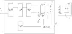
- a charging system for a terminalincludes: a power adapter, the power adapter includes: a first rectifying unit, wherein the first rectifying unit performs an input alternating current Rectifying to output a voltage of the first pulsation waveform; a switching unit configured to modulate a voltage of the first pulsation waveform according to a control signal; and a transformer for modulating the first pulsation according to the modulation a voltage of the waveform outputs a voltage of the plurality of pulsating waveforms; a synthesizing unit configured to synthesize voltages of the plurality of pulsating waveforms to output a second alternating current, wherein the second alternating current is positive half of each period The peak voltage of the portion is greater than the absolute value of the valley voltage of the negative half; the first charging interface, the first charging interface is connected to the output end of the synthesizing unit; the sampling unit, the sampling unit is used for the second The voltage
- the terminalincludes a second charging interface and a battery, and the second charging interface is connected to the battery, wherein when the second charging interface is connected to the first charging interface, the second charging interface is The second alternating current is applied to the battery.
- a charging system for a terminalcan output a second alternating current by controlling a power adapter, and directly load a second alternating current output by the power adapter to the battery of the terminal, thereby realizing direct output voltage/current of the alternating current waveform.
- the batteryis quickly charged.
- the magnitude of the output voltage/current of the AC waveformis periodically changed, and the peak voltage of the positive half of each cycle is greater than the absolute value of the valley voltage of the negative half, which can be reduced compared with the conventional constant voltage constant current.
- Lithium battery lithium precipitation phenomenonimprove battery life, and can also reduce the probability and strength of the arc of the contact of the charging interface, improve the life of the charging interface, and help reduce the polarization effect of the battery, improve the charging speed, Reduce the heat of the battery and ensure the safety and reliability of the terminal when charging.
- the power adaptersince the power adapter outputs the voltage of the AC waveform, it is not necessary to provide an electrolytic capacitor in the power adapter, which not only simplifies and miniaturizes the power adapter, but also greatly reduces the cost.
- a power adapterincludes: a first rectifying unit, wherein the first rectifying unit is configured to rectify an input alternating current to output a voltage of a first pulsating waveform; a unit, the switch unit is configured to modulate a voltage of the first pulsation waveform according to a control signal, and the transformer is configured to output a voltage of the plurality of pulsation waveforms according to the voltage of the modulated first pulsation waveform; a synthesizing unit, configured to synthesize voltages of the plurality of pulsating waveforms to output a second alternating current, wherein a peak voltage of a positive half of each period of the second alternating current is greater than a valley voltage of the negative half An absolute value; the first charging interface is connected to an output end of the synthesizing unit, and the first charging interface is configured to pass the second charging when connected to the second charging interface of the terminal The interface loads the second alternating current to the
- the second alternating currentis output through the first charging interface, and the second alternating current is directly loaded to the battery of the terminal through the second charging interface of the terminal, so that the output voltage/current of the alternating current waveform can be directly The battery is quickly charged.
- the magnitude of the output voltage/current of the AC waveformis periodically changed, and the peak voltage of the positive half of each cycle of the second alternating current is greater than the absolute value of the valley voltage of the negative half, compared with the conventional constant voltage constant current.
- a charging apparatusincludes: a charging receiving end, the charging receiving end is configured to receive an alternating current mains; a voltage adjusting circuit, and an input end of the voltage adjusting circuit The charging receiving end is connected, the output end of the voltage adjusting circuit is connected to the battery, and the voltage adjusting circuit is configured to perform an adjustment process on the AC mains to output a second alternating current, and directly load the second alternating current Recharging the battery to the battery, wherein a peak voltage of a positive half of each cycle of the second alternating current is greater than an absolute value of a valley voltage of a negative half; a central control module, the central control module is The voltage adjustment circuit is controlled to regulate the voltage and/or current of the second alternating current in response to a charging demand of the battery.
- the charging device of the embodiment of the present inventionby adjusting the AC mains, it is possible to output a second alternating current that satisfies the battery charging requirement, directly load the battery, and quickly charge the battery, thereby being compared with the conventional constant voltage constant current charging phase.
- the lithium batterycan be reduced in lithium deposition, the service life of the battery can be improved, and the probability and intensity of the arc of the contact of the charging interface can be reduced, the life of the charging interface can be improved, and the polarization effect of the battery can be reduced.
- Improve the charging speedreduce the heat of the battery, and ensure the safety and reliability of the battery when charging.
- a charging methodincludes the steps of: receiving AC mains; adjusting the AC mains to output a second alternating current, and the second alternating current Directly loading a battery to charge the battery, wherein a peak voltage of a positive half of each cycle of the second alternating current is greater than an absolute value of a valley voltage of the negative half; adjusting a voltage of the second alternating current and/or Current in response to the charging requirements of the battery.
- the second alternating current that satisfies the battery charging requirementcan be directly loaded to the battery, and the battery is quickly charged, thereby being compared with the conventional constant voltage constant current charging. It can reduce the lithium deposition phenomenon of the lithium battery, improve the service life of the battery, and can also reduce the probability and strength of the arc of the contact of the charging interface, improve the life of the charging interface, and help reduce the polarization effect of the battery and improve Charging speed, reduce battery heat, ensure safe and reliable battery charging.
- a charging method for a terminalincludes the following steps: when a first charging interface of a power adapter is connected to a second charging interface of the terminal, The alternating current is rectified to output a voltage of the first pulsation waveform; the voltage of the first pulsation waveform is modulated by controlling the switching unit, and the voltage of the plurality of pulsating waveforms is output by transformation of the transformer; and the plurality of pulsations are The voltages of the waveforms are combined to output a second alternating current, wherein the peak voltage of the positive half of each cycle of the second alternating current is greater than the absolute value of the valley voltage of the negative half; said first through said second charging interface Dielectrically charging the battery to the terminal; sampling the voltage and/or current of the second alternating current to obtain a voltage sample value and/or a current sample value; controlling according to the voltage sample value and/or the current sample value pair
- the duty cycle of the control signal of the switching unitis
- a charging method for a terminalcan output a second alternating current that meets a charging demand by controlling a power adapter, and directly load a second alternating current output by the power adapter to a battery of the terminal, thereby realizing an output voltage of the alternating current waveform.
- Currentdirectly charges the battery quickly.
- the magnitude of the output voltage/current of the AC waveformis periodically changed, and the peak voltage of the positive half of each cycle of the second alternating current is greater than the absolute of the valley voltage of the negative half
- the valuecan reduce the lithium deposition phenomenon of the lithium battery, improve the service life of the battery, and can also reduce the probability and intensity of the arc of the contact of the charging interface, and improve the life of the charging interface. It also helps to reduce the polarization effect of the battery, increase the charging speed, reduce the heat of the battery, and ensure the safety and reliability of the terminal when charging.
- the power adapteroutputs the voltage of the AC waveform, it is not necessary to provide an electrolytic capacitor in the power adapter, which not only simplifies and miniaturizes the power adapter, but also greatly reduces the cost.
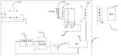
- FIG. 1Ais a block schematic diagram of a charging system for a terminal in accordance with an embodiment of the present invention
- 1Bis a circuit diagram of a synthesizing unit in accordance with one embodiment of the present invention.
- 1Cis a circuit diagram of a synthesizing unit according to another embodiment of the present invention.
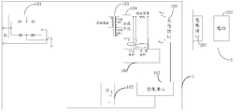
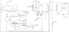
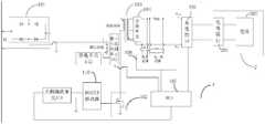
- FIG. 2is a block diagram showing a charging system for a terminal using a flyback switching power supply according to an embodiment of the present invention
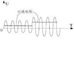
- FIG. 3is a schematic diagram showing a waveform of a charging voltage outputted from a power adapter to a battery according to an embodiment of the present invention
- FIG. 4is a schematic diagram of a control signal output to a switching unit according to an embodiment of the present invention.
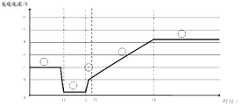
- FIG. 5is a schematic diagram of a fast charging process according to an embodiment of the present invention.
- FIG. 6is a block schematic diagram of a charging system for a terminal in accordance with one embodiment of the present invention.
- FIG. 7is a block diagram showing a charging system for a terminal according to another embodiment of the present invention.
- FIG. 8is a block diagram showing a charging system for a terminal according to still another embodiment of the present invention.
- FIG. 9is a block schematic diagram of a charging system for a terminal in accordance with still another embodiment of the present invention.
- FIG. 10is a block schematic diagram of a sampling unit in accordance with one embodiment of the present invention.
- FIG. 11is a block diagram showing a charging system for a terminal according to still another embodiment of the present invention.
- FIG. 12is a block diagram showing a terminal according to an embodiment of the present invention.
- FIG. 13is a block diagram showing a terminal according to another embodiment of the present invention.
- FIG. 14is a flowchart of a charging method for a terminal according to an embodiment of the present invention.
- FIG. 15is a block schematic diagram of a charging device in accordance with an embodiment of the present invention.
- FIG. 16is a block schematic diagram of a power adapter in accordance with one embodiment of the present invention.
- Figure 17is a block schematic diagram of a terminal in accordance with one embodiment of the present invention.
- a charging system for a terminal, a power adapter, a charging device, a charging method, and a charging method for the terminal according to an embodiment of the present inventionwill be described below with reference to the accompanying drawings.
- a charging system for a terminal proposed by an embodiment of the present inventionincludes a power adapter 1 and a terminal 2.
- the power adapter 1includes a first rectifying unit 101, a switching unit 102, a transformer 103, a synthesizing unit 104, a first charging interface 105, a sampling unit 106, and a control unit 107.
- the first rectifying unit 101rectifies the input alternating current (mains, for example, AC220V) to output a voltage of the first pulsation waveform, such as a head wave voltage, wherein, as shown in FIG. 2, the first rectifying unit 101 may be composed of four diodes. Full bridge rectifier circuit.
- the switch unit 102is configured to modulate the voltage of the first pulsation waveform according to the control signal, wherein the switch unit 102 can be composed of a MOS transistor, and performs PWM (Pulse Width Modulation) control on the MOS transistor to perform the threshold wave voltage. Chopping modulation.
- PWMPulse Width Modulation
- the transformer 103is configured to output voltages of the plurality of pulsating waveforms according to the voltage of the modulated first pulsation waveform
- the synthesizing unit 104is configured to synthesize the voltages of the plurality of pulsating waveforms to output the second alternating current, wherein the second alternating current
- the peak voltage of the positive half of the cycleis greater than the absolute value of the valley voltage of the negative half, and the voltage waveform of the second alternating current can be as Figure 3 shows.
- the power adaptermay employ a flyback switch unit.
- the transformer 103includes a primary winding, a first secondary winding and a second secondary winding, one end of the primary winding is connected to the first output end of the first rectifying unit 101, and the second output end of the first rectifying unit 101 is grounded, the primary The other end of the winding is connected to the switching unit 102 (for example, the switching unit 102 is a MOS transistor, here the other end of the primary winding is connected to the drain of the MOS transistor), the first secondary winding and the first The second secondary windings are both connected to the synthesizing unit 104, and the transformer 103 is configured to output a voltage of the second pulsating waveform through the first secondary winding according to the voltage of the modulated first pulsation waveform, and according to the modulated The voltage of the first pulsation waveform outputs a voltage of the third pulsation waveform through the second secondary winding.
- the synthesizing unit 104may include: two controllable switching circuits formed by electronic switching devices such as MOS tubes, and controlling two controllable switching circuits to be turned on or off.
- the control module of the disconnection, the two controllable switch circuitsare alternately turned on and alternately turned off. For example, when the control module controls one of the controllable switch circuits to be turned on and the other controllable switch circuit is turned off, the output of the synthesizing unit 104 at this time is output. It is a half cycle waveform of the second alternating current.
- the synthesizing unit 104outputs the other half cycle waveform of the second alternating current.
- the control module hereincan also adopt the above-mentioned control unit 107, for example, as shown in FIG. 1C.
- the transformer 103is a high frequency transformer, and its operating frequency may be 50 kHz to 2 MHz.
- the high frequency transformercouples the voltage of the modulated first pulsation waveform to the secondary, and the secondary winding, for example, the first secondary winding and the second time.
- the stage windingsare output.
- a high-frequency transformercan be used, and a high-frequency transformer can be used as compared with a low-frequency transformer (a low-frequency transformer is also called a power frequency transformer, and is mainly used to refer to a frequency of a commercial power, for example, an alternating current of 50 Hz or 60 Hz.
- the small sizemakes it possible to miniaturize the power adapter 1.
- the first charging interface 105is connected to the output end of the synthesizing unit 104, and the sampling unit 106 is configured to sample the voltage and/or current of the second alternating current to obtain a voltage sampling value and/or a current sampling value
- the control unit 107is connected to the sampling unit 106 and the switching unit 102, respectively, and the control unit 107 outputs the control signal to the switching unit. 102, and adjusting the duty ratio of the control signal according to the voltage sampling value and/or the current sampling value, so that the second alternating current meets the charging requirement of the terminal.
- the terminal 2includes a second charging interface 201 and a battery 202.
- the second charging interface 201is connected to the battery 202.
- the second The charging interface 201loads the second alternating current to the battery 202 to effect charging of the battery 202.
- the control unit 107adjusts the duty ratio of the control signal, such as the PWM signal, according to the voltage and/or current output by the sampled power adapter, that is, the voltage and/or current of the second alternating current, and adjusts the output of the synthesizing unit in real time.
- the closed-loop adjustment controlis implemented, so that the second alternating current meets the charging requirement of the terminal, and the battery is safely and reliably charged.
- the charging voltage waveform outputted to the batteryis adjusted by the duty ratio of the PWM signal as shown in FIG. 3 .
- the adjustment commandcan be generated according to the voltage sampling value, the current sampling value, or the voltage sampling value and the current sampling value.
- the voltage of the first ripple waveform after the full bridge rectificationthat is, the head wave voltage is directly modulated by PWM, and sent to the high frequency transformer through the high frequency transformer.
- the primaryis coupled to the secondary, and then the second alternating current of the alternating current waveform is synthesized or spliced through the synthesis unit, and directly delivered to the battery to achieve rapid charging of the battery.
- the voltage amplitude of the second alternating currentcan be adjusted by the duty ratio of the PWM signal, so that the output of the power adapter satisfies the charging requirement of the battery.
- the power adapter of the embodiment of the present inventioncancels the primary and secondary electrolytic capacitors, and directly charges the battery by the voltage of the AC waveform, thereby reducing the volume of the power adapter, realizing miniaturization of the power adapter, and greatly cut costs.
- control unit 107may be an MCU (Micro Controller Unit), that is, a microprocessor integrated with a switch drive control function and a voltage current adjustment control function.
- MCUMicro Controller Unit
- control unit 107is further configured to adjust the frequency of the control signal according to the voltage sampling value and/or the current sampling value, that is, the PWM signal outputted to the switching unit 102 can be controlled to continue to output for a period of time before stopping. Output, after the predetermined time is stopped, the output of the PWM signal is turned on again, so that the voltage applied to the battery is intermittent, and the battery is intermittently charged, thereby avoiding the safety hazard caused by the serious heat generation when the battery is continuously charged, and improving the battery charging. Reliability and security.
- the degree of polarizationis easily aggravated during the charging process, and the continuous charging method makes the polarization performance more obvious. It also increases the possibility of lithium formation, which affects the safety performance of the battery.
- the continuous chargingcauses the accumulation of heat due to charging, which causes the internal temperature of the battery to continuously rise. When the temperature exceeds a certain limit, the performance of the battery is limited, and the safety hazard is increased.
- the intermittent output of the power adapteris equivalent to introducing a battery rest process in the process of charging the battery, which can alleviate the possibility of polarization caused by continuous charging.
- the phenomenon of lithiumis precipitated, and the effect of the continuous accumulation of heat generation is weakened, the effect of cooling is achieved, and the battery charging is reliable and safe.
- the control signal outputted to the switch unit 102may be as shown in FIG. 4, and the PWM signal is outputted for a period of time, then the output is stopped for a period of time, and then the PWM signal is output for a period of time, so that the control signal output to the switch unit 102 is separated.
- the frequencyis adjustable.
- control unit 107is connected to the first charging interface 105.
- the control unit 107is further configured to communicate with the terminal 2 through the first charging interface 105 to obtain status information of the terminal 2.
- control unit 107is further configured to perform a duty ratio of the control signal, for example, the PWM signal, according to the state information of the terminal, the voltage sampling value, and/or the current sampling value. Adjustment.
- the status information of the terminalmay include a quantity of the battery, a temperature of the battery, a battery voltage/current of the terminal, interface information of the terminal, information of a path impedance of the terminal, and the like.
- the first charging interface 105includes a power line for charging the battery and a data line for communicating with the terminal.
- the power adapter 1 and the terminal 2can mutually transmit a communication inquiry command, and after receiving the corresponding response command, the power adapter 1 establishes communication with the terminal 2.
- the control unit 107can acquire status information of the terminal 2, thereby negotiating the charging mode and charging parameters (such as charging current, charging voltage) with the terminal 2, and controlling the charging process.
- the charging mode supported by the power adapter and/or the terminalmay include a normal charging mode and a fast charging mode.
- the charging speed of the fast charging modeis greater than the charging speed of the normal charging mode (for example, the charging current of the fast charging mode is larger than the charging current of the normal charging mode).
- the normal charging modecan be understood as a charging mode with a rated output voltage of 5V and a rated output current of 2.5A or less.
- D+ and D- in the power adapter output port data linecan be short-circuited.
- the fast charging mode in the embodiment of the present inventionis different.
- the power adaptercan communicate with the terminal by using D+ and D- in the data line to implement data exchange, that is, between the power adapter and the terminal.
- the fast charging commandcan be sent to each other: the power adapter sends a fast charging inquiry command to the terminal, and after receiving the fast charging response command of the terminal, according to the response command of the terminal, the power adapter acquires the state information of the terminal, turns on the fast charging mode, and quickly charges.
- the charging current in the modecan be greater than 2.5A, for example, can reach 4.5A or even larger.
- the embodiment of the present inventiondoes not specifically limit the normal charging mode.
- the charging speed (or current) of one charging modeis greater than the charging speed of the other charging mode, the charging speed is slow.
- the charging modecan be understood as a normal charging mode.
- the charging power in the fast charging modemay be greater than or equal to 15 W with respect to the charging power.
- control unit 107communicates with the terminal 2 through the first charging interface 105 to determine a charging mode, wherein The charging mode includes a fast charging mode and a normal charging mode.
- the power adapter and the terminalare connected through a Universal Serial Bus (USB) interface, and the USB interface may be a normal USB interface or a micro USB interface.
- the data line in the USB interfacethat is, the data line in the first charging interface, is used for two-way communication between the power adapter and the terminal, and the data line may be a D+ line and/or a D- line in the USB interface, so-called two-way communication. It can refer to the interaction between the power adapter and the terminal.
- the power adapterperforms two-way communication with the terminal through a data line in the USB interface to determine to charge the terminal using the fast charging mode.
- the power adapterin the process of negotiating whether the power adapter and the terminal use the fast charging mode to charge the terminal, the power adapter can only remain connected with the terminal, does not charge, and can also charge the terminal by using a normal charging mode.
- the charging of the terminalis performed by using a small current, which is not specifically limited in the embodiment of the present invention.
- the power adapteradjusts a charging current to a charging current corresponding to the fast charging mode to charge the terminal.
- the charging currentcan be directly adjusted to the charging current corresponding to the fast charging mode, or the charging current of the fast charging mode can be negotiated with the terminal, for example, according to the current power of the battery in the terminal. Determine the charging current corresponding to the fast charging mode.
- the power adapterdoes not blindly increase the output current for fast charging, but needs to perform two-way communication with the terminal to negotiate whether the fast charging mode can be adopted, which improves the fast charging process compared with the prior art. safety.
- control unit 107performs bidirectional communication with the terminal through a data line in the first charging interface to determine that when the terminal is charged by using the fast charging mode, the control unit The terminal sends a first instruction, where the first instruction is used to query whether the terminal starts the fast charging mode; the control unit receives a reply instruction of the first instruction from the terminal, the first instruction The reply command is used to indicate that the terminal agrees to enable the fast charging mode.
- the control unitbefore the control unit sends the first instruction to the terminal, the power adapter and the terminal are charged by the normal charging mode, and the control unit is After determining that the charging duration of the normal charging mode is greater than a preset threshold, sending the first instruction to the terminal.
- the power adaptermay consider that the terminal has identified itself as a power adapter, and may open the fast charging inquiry communication.
- the first instructionis sent to the terminal.
- control unitis further configured to: by controlling the switch unit to control the power adapter to adjust a charging current to a charging current corresponding to the fast charging mode, and in the power adapter Before the charging current corresponding to the fast charging mode is charging the terminal, the control unit performs bidirectional communication with the terminal through a data line in the first charging interface to determine a charging voltage corresponding to the fast charging mode. And controlling the power adapter to adjust the charging voltage to a charging voltage corresponding to the fast charging mode.
- the control unitwhen the control unit performs bidirectional communication with the terminal through a data line in the first charging interface to determine a charging voltage corresponding to the fast charging mode, the control unit The terminal sends a second instruction, the second instruction is used to query whether a current output voltage of the power adapter is suitable as a charging voltage of the fast charging mode; and the control unit receives the second sent by the terminal a reply instruction of the instruction, the reply instruction of the second instruction is used to indicate that the current output voltage of the power adapter is suitable, high or low; and the control unit determines the fast according to the reply instruction of the second instruction Charging voltage for charging mode.
- control unitfurther passes the data line in the first charging interface with the data line before controlling the power adapter to adjust a charging current to a charging current corresponding to the fast charging mode.
- the terminalperforms two-way communication to determine a charging current corresponding to the fast charging mode.
- the control unitperforms bidirectional communication with the terminal through a data line in the first charging interface to determine a charging current corresponding to the fast charging mode, where the control unit The terminal Sending a third instruction, the third instruction is used to query a maximum charging current currently supported by the terminal; the control unit receives a reply instruction of the third instruction sent by the terminal, and the reply instruction of the third instruction And configured to indicate a maximum charging current currently supported by the terminal; the control unit determines a charging current of the fast charging mode according to the return instruction of the third instruction.
- the power adaptercan directly determine the above maximum charging current as the charging current of the fast charging mode, or set the charging current to a certain current value smaller than the maximum charging current.
- control unitfurther performs, by using a data line in the first charging interface, with the terminal. Two-way communication to continuously adjust the charging current of the power adapter output to the battery by controlling the switching unit.
- the power adaptercan continuously query the current status information of the terminal, such as the battery voltage of the terminal, the battery power, etc., so as to continuously adjust the charging current of the power adapter output to the battery.
- the control unitperforms bidirectional communication with the terminal through a data line in the first charging interface to continuously adjust charging of the power adapter output to the battery by controlling the switch unit.
- the control unitsends a fourth instruction to the terminal, the fourth instruction is used to query a current voltage of a battery in the terminal; and the control unit receives the fourth instruction sent by the terminal
- the reply instruction of the fourth instructionis used to indicate a current voltage of a battery in the terminal; the control unit adjusts the power adapter output to the switch unit according to a current voltage of the battery The charging current of the battery.
- control unitoutputs the power adapter by controlling the switch unit according to a current voltage of the battery and a corresponding relationship between a preset battery voltage value and a charging current value.
- the charging current of the batteryis adjusted to a charging current value corresponding to the current voltage of the battery.
- the power adaptermay pre-store the correspondence between the battery voltage value and the charging current value, and the power adapter may also perform bidirectional communication with the terminal through the data line in the first charging interface, and obtain the stored in the terminal from the terminal side. Correspondence between the battery voltage value and the charging current value.
- the control unitfurther performs, by using a data line in the first charging interface, with the terminal. Two-way communication to determine whether there is a poor contact between the first charging interface and the second charging interface, wherein the control is determined when a poor contact between the first charging interface and the second charging interface is determined.
- the unitcontrols the power adapter to exit the fast charging mode.
- the control unitbefore determining whether the first charging interface and the second charging interface are in poor contact, is further configured to receive, from the terminal, an indication for the terminal.
- Information of the path impedancewherein the control unit sends a fourth command to the terminal, the fourth command is used to query a voltage of a battery in the terminal; and the control unit receives the first a reply command of the fourth command, the reply command of the fourth command is used to indicate a voltage of a battery in the terminal; the control unit determines the power adapter according to an output voltage of the power adapter and a voltage of the battery a path impedance to the battery; the control unit according to a path impedance of the power adapter to the battery, a path impedance of the terminal, and a path impedance of a charging line line between the power adapter and the terminal Determining whether the first charging interface and the second charging interface are in poor contact.
- the terminalcan record its path impedance in advance.
- the terminal of the same modelhas the same structure, and the path impedance of the terminal is set to the same value at the factory setting.
- the power adaptercan pre-record the path impedance of the charging line.
- the path impedance of the entire pathcan be determined according to the voltage drop across the power adapter to the battery and the current of the path.
- the contact between the first charging interface and the second charging interfacemay be considered to be poor.
- control unitbefore the power adapter exits the fast charging mode, the control unit further sends a fifth instruction to the terminal, where the fifth instruction is used to indicate the first charging interface. And the second charge Poor contact between electrical interfaces.
- the power adapterAfter the power adapter sends the fifth command, it can exit the fast charge mode or reset.
- the terminal 2further includes a charging control switch 203 and a controller 204.
- the charging control switch 203for example, a switching circuit composed of an electronic switching device, is connected to the second charging interface 201 and the battery 202.
- the charging control switch 203is used to turn off or turn on the charging process of the battery, so that the charging process of the battery can also be controlled from the terminal side to ensure safe and reliable charging of the battery.
- the terminal 2further includes a communication unit 205 for establishing two-way communication between the controller 204 and the control unit 107 through the second charging interface 201 and the first charging interface 105. That is, the terminal and the power adapter can perform bidirectional communication through a data line in the USB interface, and the terminal supports a normal charging mode and a fast charging mode, wherein the charging current of the fast charging mode is greater than the charging current of the normal charging mode,
- the controllerperforms bidirectional communication with the control unit through the communication unit such that the power adapter determines to charge the terminal using the fast charging mode, so that the control unit controls the power adapter to correspond to the fast charging mode.
- the charging currentis output to charge the battery in the terminal.
- the power adapterdoes not blindly increase the output current for fast charging, but needs to perform two-way communication with the terminal, and negotiate whether the fast charging mode can be adopted, which improves the safety of the fast charging process compared with the prior art. Sex.
- the controllerreceives, by using a communication unit, a first instruction sent by the control unit, where the first instruction is used to query whether the terminal enables the fast charging mode; Sending, by the communication unit, a reply instruction of the first instruction to the control unit, where the reply instruction of the first instruction is used to indicate the The terminal agrees to turn on the fast charging mode.
- the control unitbefore the controller receives the first instruction sent by the control unit by using the communication unit, the power adapter charges the battery in the terminal by using the normal charging mode, the control unit After determining that the charging duration of the normal charging mode is greater than a preset threshold, the control unit sends the first instruction to a communication unit in the terminal, and the controller receives the first part sent by the control unit by using a communication unit An instruction.
- the power adapteroutputs according to a charging current corresponding to the fast charging mode
- the controllerperforms bidirectional with the control unit by using a communication unit before charging the battery in the terminal. Communicating so that the power adapter determines a charging voltage corresponding to the fast charging mode.
- the controllerreceives a second instruction sent by the control unit, where the second instruction is used to query whether a current output voltage of the power adapter is suitable for charging in the fast charging mode.
- the controllersends a reply instruction of the second instruction to the control unit, and the reply instruction of the second instruction is used to indicate that the current output voltage of the power adapter is suitable, high or low.
- the controllerperforms bidirectional communication with the control unit, so that the power adapter determines a charging current corresponding to the fast charging mode.
- the controllerreceives a third instruction sent by the control unit, the third instruction is used to query a maximum charging current currently supported by the terminal; the controller sends the third instruction to the control unit And a reply instruction of the third instruction is used to indicate a maximum charging current currently supported by the terminal, so that the power adapter determines a charging current corresponding to the fast charging mode according to the maximum charging current.
- the controllerperforms bidirectional communication with the control unit, so that the power adapter continuously adjusts The power adapter outputs a charging current to the battery.
- the controllerreceives a fourth instruction sent by the control unit, the fourth instruction is used to query a current voltage of a battery in the terminal; the controller sends the fourth instruction to the control unit Reply instruction, said The reply command of the fourth instruction is used to indicate a current voltage of the battery in the terminal, so that the power adapter continuously adjusts the charging current output by the power adapter to the battery according to the current voltage of the battery.
- the controllerperforms bidirectional communication with the control unit through a communication unit, so that the power adapter Determining whether the first charging interface and the second charging interface are in poor contact.
- the controllerreceives a fourth instruction sent by the control unit, the fourth instruction is used to query a current voltage of a battery in the terminal; the controller sends the fourth instruction to the control unit Responding instruction, the reply instruction of the fourth instruction is used to indicate a current voltage of a battery in the terminal, so that the control unit determines the first according to an output voltage of the power adapter and a current voltage of the battery Whether the contact between the charging interface and the second charging interface is poor.
- the controllerreceives a fifth instruction sent by the control unit, where the fifth instruction is used to indicate a poor contact between the first charging interface and the second charging interface.
- the power adaptercan perform a fast charging communication process with the terminal, and realize fast charging of the battery after one or more handshakes.
- the fast charging communication flow of the embodiment of the present invention and the various stages included in the fast charging processare described in detail below with reference to FIG. It should be understood that the communication steps or operations illustrated in FIG. 5 are merely examples, and that other operations of the present invention or variations of the various operations in FIG. 5 may be performed. Moreover, the various stages in FIG. 5 may be performed in a different order than that presented in FIG. 5, and it is also possible that not all operations in FIG. 5 are to be performed. It should be noted that the curve in FIG. 5 is a trend of the peak value or the average value of the charging current, and is not the actual charging current curve.
- the fast charge processcan consist of five phases:
- the terminalcan detect the type of the power supply device through the data lines D+ and D-.
- the current absorbed by the terminalcan be greater than the preset current.
- Threshold I2for example, may be 1A.
- the power adapterdetects that the power adapter output current is greater than or equal to I2 within a preset duration (for example, may be continuous T1 time)
- the power adapterconsiders that the terminal has completed the type identification of the power supply device, and the power adapter turns on the adapter and the terminal.
- the power adaptersends an instruction 1 (corresponding to the first instruction described above) to inquire whether the terminal turns on the fast charging mode (or referred to as flash charging).
- the output current of the power adapteris detected again, when the output current of the power adapter is within a preset continuous time (for example, it may be continuous T1 time) If it is still greater than or equal to I2, the request is again initiated to ask the terminal whether to enable the fast charging mode, and the above steps of phase 1 are repeated until the terminal replies to agree to turn on the fast charging mode, or the output current of the power adapter no longer satisfies the condition of greater than or equal to I2.
- a preset continuous timefor example, it may be continuous T1 time
- the fast charge charging processis turned on, and the fast charge communication process enters the second stage.
- the head wave voltage output by the power adaptermay include a plurality of gear positions, and the power adapter sends an instruction 2 (corresponding to the second command) to the terminal to inquire whether the output voltage of the terminal power adapter matches the current voltage of the battery (or is suitable, that is, is suitable As the charging voltage in the fast charging mode, that is, whether the charging demand is satisfied.
- the terminalreplies that the output voltage of the power adapter is high or low or matches. If the power adapter receives feedback from the terminal about the adapter's output voltage being high or low, the control unit adjusts the duty cycle of the PWM signal to the power adapter. The output voltage is adjusted to one grid position, and the command 2 is sent to the terminal again to re-inquire whether the output voltage of the terminal power adapter matches.
- the power adapterAfter the power adapter receives the feedback that the terminal responds to the output voltage matching of the power adapter, the power adapter sends an instruction 3 (corresponding to the third instruction described above) to the terminal to query the maximum charging current currently supported by the terminal, and the terminal answers
- the complex power adapterhas its current maximum charge current value and enters phase 4.
- the power adapterAfter the power adapter receives the feedback of the currently supported maximum charging current value replied by the terminal, the power adapter can set its output current reference value, and the control unit 107 adjusts the duty ratio of the PWM signal according to the current reference value, so that the output current of the power adapter satisfies
- the terminal charging current demandthat is, enters the constant current phase, where the constant current phase means that the output current peak value or the current average value of the power adapter remains substantially the same (that is, the output current peak value or the current average value changes little, such as It varies within a range of 5% of the output current peak or average value), that is, the peak current of the second alternating current is kept constant every cycle.
- the power adapterWhen entering the constant current change phase, the power adapter sends an instruction 4 (corresponding to the fourth instruction described above) at intervals, inquiring about the current voltage of the terminal battery, and the terminal can feed back the current voltage of the terminal battery to the power adapter, and the power adapter can be based on the terminal. Regarding the feedback of the current voltage of the terminal battery, it is determined whether the USB contact, that is, the contact between the first charging interface and the second charging interface is good, and whether the current charging current value of the terminal needs to be lowered. When the power adapter determines that the USB contact is bad, the command 5 (corresponding to the fifth command described above) is sent, and then reset to re-enter phase 1.
- the command 5(corresponding to the fifth command described above) is sent, and then reset to re-enter phase 1.
- the data corresponding to the path impedance of the terminalmay be attached to the data corresponding to the instruction 1, and the terminal path impedance data may be used in the stage. 5 Determine if the USB contact is good.
- the terminalagrees to start the fast charging mode, and the time when the power adapter adjusts the voltage to the appropriate value may be controlled within a certain range, and the time may exceed the predetermined range, and the terminal may It is determined that the request is abnormal and a quick reset is performed.
- the terminalin phase 2, can make a power supply to the power adapter when the output voltage of the power adapter is adjusted to be higher than ⁇ V ( ⁇ V is about 200-500 mV) compared to the current battery voltage.
- ⁇ Vis about 200-500 mV
- the output voltage of the adapteris suitable/matched for feedback.
- the control unit 107adjusts the duty ratio of the PWM signal according to the voltage sampling value, thereby The output voltage is adjusted.
- the speed adjustment speed of the output current value of the power adaptercan be controlled within a certain range, so that the fast charge abnormal interruption due to the excessive adjustment speed can be avoided.
- the magnitude of the change in the magnitude of the output current value of the power adaptermay be controlled within 5%, that is, may be regarded as a constant current phase.
- the power adaptermonitors the charging loop impedance in real time, ie, by measuring the output voltage of the power adapter, the current charging current, and the read terminal battery voltage, monitoring the entire charging loop impedance.
- the charging loop impedance > terminal path impedance + fast charge data line impedanceis measured, it can be considered that the USB contact is poor and the fast charge reset is performed.
- the communication time interval between the power adapter and the terminalcan be controlled within a certain range to avoid a fast charge reset.
- the stop of the fast charge modecan be divided into two types: a recoverable stop and an unrecoverable stop:
- the fast chargestops and resets, and enters the stage 1
- the terminaldoes not agree to turn on the fast charging mode, and the fast charging communication process does not enter the stage 2, and the fast charging process stopped at this time may be Unrecoverable stop.
- the fast chargeis stopped and reset to enter phase 1.
- the terminalagrees to turn on the fast charge mode to resume the fast charge and charge process, and the stop is fast.
- the charging processcan be a recoverable stop.
- the fast chargestops and resets to enter phase 1, and after entering phase 1, the terminal does not agree to turn on the fast charge mode.
- the terminal Agree to turn on the fast charge to resume the fast charge process, and the fast charge process that stops at this timecan be a recoverable stop.
- the communication step or operation shown in FIG. 5 aboveis only an example.
- the handshake communication between the terminal and the adaptermay also be initiated by the terminal. That is, the terminal sends the command 1 to ask whether the adapter turns on the fast charging mode (or called flash charging).
- the terminalreceives the power adapter's reply command indicating that the power adapter agrees to turn on the fast charging mode, the fast charging process is turned on.
- a constant voltage charging phasemay be included, that is, in the phase 5, the terminal may be connected to the power adapter.
- the current voltage of the terminal batteryis fed back, and as the voltage of the terminal battery continues to rise, when the current voltage of the terminal battery reaches the constant voltage charging voltage threshold, the charging is transferred to the constant voltage charging phase, and the control unit 107 is based on the voltage reference value (ie, The constant voltage charging voltage threshold adjusts the duty ratio of the PWM signal, so that the output voltage of the power adapter satisfies the terminal charging voltage requirement, that is, the basic holding voltage is constantly changed.
- the constant voltage chargingmeans that the peak voltage of the second alternating current is substantially constant.
- obtaining the output voltage of the power adapterrefers to obtaining the peak voltage or voltage average value of the second alternating current
- obtaining the output current of the power adapterrefers to acquiring the second alternating current. Peak current or current average.
- the power adapter 1further includes: a rectifying and filtering unit 109 and a controllable switch 108 for controlling whether the rectifying and filtering unit 109 operates, and the rectifying and filtering unit 109 is used for Rectifying and filtering one of the voltages of the plurality of pulsating waveforms to output a second direct current, for example, 5V, wherein the control unit 107 is further configured to: when determining that the charging mode is a normal charging mode, by controlling the Controlling the switch 108 to operate the rectifying and filtering unit 109 and controlling the synthesizing unit 104 to stop operating, the rectifying and filtering unit 109 outputs the second direct current to charge the battery, and determining that the charging mode is In the fast charging mode, the rectifying and filtering unit 109 is stopped by controlling the controllable switch 108, and the synthesizing unit 104 is controlled. Work is performed to load the second alternating current to the battery.
- the rectifying and filtering unit 109includes a rectifying diode and a filter capacitor, and the filter capacitor can support a standard charging of 5V, that is, corresponding to a normal charging mode, and the controllable switch 108 can be composed of a semiconductor switching device such as a MOS transistor.
- the control unit 107controls the controllable switch 108 to be closed, and controls the rectifying and filtering unit 109 to operate, so that the DC charging technology can be better compatible, that is, The second direct current is applied to the battery of the terminal to realize DC charging of the battery.
- the filtering partincludes electrolytic capacitors in parallel and common capacitors, that is, small capacitors (such as solid capacitors) that support 5V standard charging. Since the electrolytic capacitor occupies a relatively large volume, in order to reduce the size of the power adapter, the electrolytic capacitor in the power adapter can be removed, and a capacitor having a small capacitance value is reserved.
- the branch of the small capacitorcan be controlled to be turned on, the current is filtered, a small power stable output is realized, and the battery is DC-charged; when the fast charging mode is used, the second direct current is directly output and applied to the battery. To achieve fast battery charging.
- the control unit 107is further configured to: when determining that the charging mode is the fast charging mode, acquire a charging current and/or a charging voltage corresponding to the fast charging mode according to the state information of the terminal, and charge according to the fast charging mode.
- the current and/or charging voltageregulates the duty cycle of the control signal, such as the PWM signal. That is, when determining that the current charging mode is the fast charging mode, the control unit 107 determines the state information of the terminal, such as the voltage, the amount of electricity, the temperature of the battery, the operating parameters of the terminal, and the power consumption information of the application running on the terminal.
- the charging current and/or the charging voltage corresponding to the fast charging modeare obtained, and then the duty ratio of the control signal is adjusted according to the obtained charging current and/or the charging voltage, so that the output of the power adapter satisfies the charging requirement, and the battery is quickly charged.
- the status information of the terminalincludes the temperature of the battery. And, when the temperature of the battery is greater than the first preset temperature threshold or the temperature of the battery is less than the second preset temperature threshold, if the current charging mode is the fast charging mode, the fast charging mode is switched to the normal charging mode, wherein the first The preset temperature threshold is greater than the second preset temperature threshold. That is to say, when the temperature of the battery is too low (for example, corresponding to less than the second preset temperature threshold) or too high (for example, corresponding to greater than the first preset temperature threshold), it is not suitable for fast charging, so fast charging is required.
- the modeis switched to the normal charging mode.
- the first preset temperature threshold and the second preset temperature thresholdmay be set or written in a storage of a control unit (eg, a power adapter MCU) according to actual conditions.
- control unit 107is further configured to control the switch unit 102 to be turned off when the temperature of the battery is greater than a preset high temperature protection threshold, that is, when the temperature of the battery exceeds the high temperature protection threshold, the control unit 107 needs to adopt The high temperature protection strategy controls the switch unit 102 to be disconnected, so that the power adapter stops charging the battery, thereby achieving high temperature protection of the battery and improving the safety of charging.
- the high temperature protection thresholdmay be different from the first temperature threshold or may be the same.
- the high temperature protection thresholdis greater than the first temperature threshold.
- the controlleris further configured to acquire a temperature of the battery, and when the temperature of the battery is greater than a preset high temperature protection threshold, control the charging control switch to be turned off, that is, The charging control switch is turned off by the terminal side, thereby turning off the charging process of the battery and ensuring charging safety.
- control unitis further configured to acquire a temperature of the first charging interface, and control the switch when a temperature of the first charging interface is greater than a preset protection temperature.
- the unitis turned off. That is, when the temperature of the charging interface exceeds a certain temperature, the control unit 107 also needs to perform a high temperature protection strategy, and the control switch unit 102 is disconnected, so that the power adapter stops charging the battery, realizes high temperature protection of the charging interface, and improves the safety of charging. .
- the controllerobtains the temperature of the first charging interface by performing bidirectional communication with the control unit, and the temperature of the first charging interface is greater than a preset
- the charging control switchis controlled to be turned off, that is, the charging control switch is turned off through the terminal side, and the charging process of the battery is turned off to ensure charging safety.
- the power adapter 1further includes a driving unit 110 such as a MOSFET driver, and the driving unit 110 is connected between the switching unit 102 and the control unit 107, and the driving unit 110 is used for The switching unit 102 is turned on or off in accordance with a control signal.
- the driving unit 110may also be integrated in the control unit 107.
- the power adapter 1further includes an isolation unit 111 connected between the driving unit 110 and the control unit 107 to implement signal isolation between the primary and secondary of the power adapter 1 (or the transformer 103). Signal isolation between the primary winding and the secondary winding).
- the isolation unit 111can be isolated by optocoupler or other isolation.
- the control unit 107can be disposed on the secondary side of the power adapter 1 (or the secondary winding side of the transformer 103) to facilitate communication with the terminal 2, making the space design of the power adapter 1 more Simple and easy.
- control unit 107 and the driving unit 110can be disposed on the primary side.
- the isolation unit 111can be disposed between the control unit 107 and the sampling unit 106 to implement the power adapter. Signal isolation between primary and secondary of 1.
- the isolation unit 111when the control unit 107 is disposed on the secondary side, the isolation unit 111 needs to be disposed, and the isolation unit 111 can also be integrated in the control unit 107. That is to say, when the primary to secondary signal is transmitted or the secondary is transmitted to the primary, it is usually necessary to provide an isolation unit for signal isolation.
- the power adapter 1further includes an auxiliary winding and a power supply unit 112.
- the auxiliary windinggenerates a voltage of the fourth pulsation waveform according to the voltage of the modulated first pulsation waveform, and the power supply unit 112 Connected to the auxiliary winding, the power supply unit 112 (including, for example, a filter voltage stabilizing module, a voltage conversion module, etc.) is used to convert the voltage of the fourth pulsation waveform to output direct current, and supply power to the driving unit 110 and/or the control unit 107, respectively.
- the power supply unit 112may be composed of a filter small capacitor, a voltage regulator chip, etc., to process and convert the voltage of the fourth pulsation waveform, and output low voltage direct current such as 3.3V or 5V.
- the power supply of the driving unit 110can be obtained by the voltage conversion of the fourth pulsation waveform by the power supply unit 112.
- the power supply thereofcan also be the voltage of the fourth pulsation waveform by the power supply unit 112. Converted.
- the power supply unit 112when the control unit 107 is disposed on the primary side, the power supply unit 112 provides two DC outputs to supply power to the driving unit 110 and the control unit 107, respectively, and light is disposed between the control unit 107 and the sampling unit 106.
- the coupling isolation unit 111implements signal separation between the primary and secondary of the power adapter 1 from.
- the power supply unit 112supplies power to the control unit 107 alone.
- the power supply unit 112separately supplies power to the driving unit 110, and the power supply of the control unit 107 is provided by the secondary, for example, outputted by the synthesizing unit 104 through a power supply unit.
- the second alternating currentis converted to a direct current power source to be supplied to the control unit 107.
- the output end of the first rectifying unit 101is further connected with a plurality of small capacitors in parallel to perform filtering.
- an LC filter circuitis connected to the output of the first rectifying unit 101.
- the power adapter 1further includes a first voltage detecting unit 113, which is respectively connected to the auxiliary winding and the control unit 107, and the first voltage detecting unit 113 The voltage for detecting the fourth pulsation waveform is used to generate a voltage detection value, wherein the control unit 107 is further configured to adjust the duty ratio of the control signal according to the voltage detection value.
- control unit 107can reflect the voltage of the second alternating current according to the voltage output by the auxiliary winding detected by the first voltage detecting unit 113, and then adjust the duty ratio of the control signal according to the voltage detection value, so that the synthesizing unit 104 The output matches the battery's charging needs.
- the sampling unit 106includes a first current sampling circuit 1061 and a first voltage sampling circuit 1062.
- the first current sampling circuit 1061is configured to sample the current of the second alternating current to obtain a current sampling value
- the first voltage sampling circuit 1062is configured to sample the voltage of the second alternating current to obtain a voltage sampling value.
- the first current sampling circuit 1061may sample the current of the second alternating current by sampling a voltage connected to a resistor (current-sense resistor) of the first output of the synthesizing unit 104.
- the first voltage sampling circuit 1062can sample the voltage of the second alternating current by sampling the voltage between the first output terminal and the second output terminal of the synthesizing unit 104.
- the first voltage sampling circuit 1062includes a peak.
- the peak voltage sampling and holding unitis configured to sample and hold the peak voltage of the second alternating current
- the zero-crossing sampling unitis configured to sample the voltage zero-crossing point of the second alternating current
- the bleeder unitis used for sampling and maintaining the peak voltage according to the voltage zero-crossing point.
- the unitperforms bleed
- the AD sampling unitis used to sample the peak voltage in the peak voltage sample-and-hold unit to obtain a voltage sample value.
- the peak voltage sample-and-hold unit, the zero-crossing sampling unit, the bleeder unit, and the AD sampling unit in the first voltage sampling circuit 1062By setting the peak voltage sample-and-hold unit, the zero-crossing sampling unit, the bleeder unit, and the AD sampling unit in the first voltage sampling circuit 1062, accurate sampling of the voltage of the second alternating current can be realized, and the voltage sampling value is guaranteed to be second.
- the peak voltage of each cycle of the alternating currentis synchronized with the peak voltage of the first pulse waveform, that is, the phase is consistent, and the amplitude change trend is consistent.
- the power adapter 1further includes a second voltage sampling circuit 114 for sampling the voltage of the first pulsation waveform, the second voltage sampling circuit 114 and the control The unit 107 is connected, wherein when the voltage value sampled by the second voltage sampling circuit 114 is greater than the first preset voltage value, the control unit 107 controls the switching unit 102 to turn on the first preset time to surge the first pulsation waveform. Voltage, spike voltage, etc. are discharged.
- the second voltage sampling circuit 114can be connected to the first output end and the second output end of the first rectifying unit 101 to sample the voltage of the first pulsation waveform, and the control unit 107 samples the second voltage.
- the voltage value sampled by the circuit 114is judged. If the voltage value sampled by the second voltage sampling circuit 114 is greater than the first preset voltage value, the power adapter 1 is subjected to a lightning strike, and a surge voltage occurs.
- the voltageis discharged to ensure the safety and reliability of the charging, and the control unit 107 controls the switch unit 102 to be turned on for a period of time to form a bleed path, which discharges the surge voltage caused by the lightning strike to prevent the lightning strike from causing interference to the terminal when the power adapter is charged. , effectively improve the safety and reliability of the terminal charging.
- the first preset voltage valuecan be calibrated according to actual conditions.
- the control unit 107in the process of charging the battery in the terminal by the power adapter, is further configured to control the switch unit 102 to be turned off when the voltage sample value is greater than the second preset voltage value, that is, The control unit 107 also determines the magnitude of the voltage sample value. If the voltage sample value is greater than the second preset voltage value, the power supply is adapted. The voltage output by the device 1 is too high. At this time, the control unit 107 is turned off by controlling the switch unit 102, so that the power adapter stops charging the terminal, that is, the control unit 107 realizes the overvoltage protection of the power adapter by controlling the shutdown of the switch unit 102. To ensure safe charging.
- the controlleracquires the voltage sampling value by performing bidirectional communication with the control unit, and controls the location when the voltage sampling value is greater than a second preset voltage value.
- the charging control switchis turned off, that is, the charging control switch is turned off through the terminal side, and the charging process of the battery is turned off to ensure charging safety.
- control unit 107is further configured to control the switch unit 102 to be turned off when the current sampling value is greater than the preset current value, that is, the control unit 107 further determines the magnitude of the current sampling value, if the current sampling value is greater than the preset current.
- the valueindicates that the current output by the power adapter 1 is too large.
- the control unit 107turns off by controlling the switch unit 102, so that the power adapter stops charging the terminal, that is, the control unit 107 realizes the power by controlling the shutdown of the switch unit 102.
- the overcurrent protection of the adapterensures safe charging.
- the controlleracquires the current sampling value by performing bidirectional communication with the control unit, and controls the charging control switch to be turned off when the current sampling value is greater than a preset current value, that is, through the terminal.
- the sideturns off the charging control switch, turns off the charging process of the battery, and ensures charging safety.
- the second preset voltage value and the preset current valuemay be set or written in the storage of the control unit (for example, the power adapter MCU) according to actual conditions.
- the terminalmay be a mobile terminal such as a mobile phone, a mobile power source such as a charging treasure, a multimedia player, a notebook computer, a wearable device, or the like.
- a charging system for a terminalcan output a second alternating current by controlling a power adapter, and directly load a second alternating current output by the power adapter to the battery of the terminal, thereby realizing direct output voltage/current of the alternating current waveform.
- the batteryis quickly charged.
- the magnitude of the output voltage/current of the AC waveformis periodically changed, and the peak voltage of the positive half of each cycle is greater than the absolute value of the valley voltage of the negative half, which can reduce lithium compared with the conventional constant voltage constant current.
- the lithium deposition of the batteryimproves the service life of the battery and also reduces the pull of the contacts of the charging interface.
- the probability and intensity of the arcimproves the life of the charging interface, and helps to reduce the polarization effect of the battery, increase the charging speed, reduce the heat generation of the battery, and ensure the safety and reliability of the terminal when charging.
- the power adaptersince the power adapter outputs the voltage of the AC waveform, it is not necessary to provide an electrolytic capacitor in the power adapter, which not only simplifies and miniaturizes the power adapter, but also greatly reduces the cost.
- the embodiment of the present inventionfurther provides a power adapter, the power adapter includes: a first rectifying unit, the first rectifying unit is configured to rectify the input alternating current to output a voltage of the first pulsating waveform; and the switching unit The switching unit is configured to modulate a voltage of the first pulsation waveform according to a control signal, and the transformer is configured to output a voltage of the plurality of pulsating waveforms according to the voltage of the modulated first pulsation waveform; a unit for synthesizing voltages of the plurality of pulsating waveforms to output a second alternating current, wherein a peak voltage of a positive half of each cycle of the second alternating current is greater than a valley voltage of the negative half An absolute value; the first charging interface is connected to an output end of the synthesizing unit, and the first charging interface is configured to pass through the second charging interface when connected to the second charging interface of the terminal Loading the second alternating current to a battery of the terminal, where
- the second alternating currentis output through the first charging interface, and the second alternating current is directly loaded to the battery of the terminal through the second charging interface of the terminal, so that the output voltage/current of the alternating current waveform can be directly The battery is quickly charged.
- the magnitude of the output voltage/current of the AC waveformis periodically changed, and the peak voltage of the positive half of each cycle of the second alternating current is greater than the absolute value of the valley voltage of the negative half, compared with the conventional constant voltage constant current.
- the electric speedreduces the heat of the battery and ensures the safety and reliability of the terminal when charging.
- the voltage of the AC waveformis output, it is not necessary to provide an electrolytic capacitor, and the power adapter can be simplified and miniaturized, and the cost can be greatly reduced.
- FIG. 14is a flowchart of a charging method for a terminal according to an embodiment of the present invention. As shown in FIG. 14, the charging method for the terminal includes the following steps:
- the AC mains of the input alternating currentie, mains, for example, 220V, 50Hz, or 60Hz
- the voltage of the first pulsating waveformfor example, 100 Hz or 120 Hz
- Taro wave voltagefor example, 100 Hz or 120 Hz
- the switch unitmay be composed of a MOS tube, and the MOS tube is subjected to PWM control to perform chopping modulation on the head wave voltage. Then, the voltage of the modulated first pulsation waveform is coupled to the secondary by the transformer, and the voltage of the plurality of pulsating waveforms is output by the secondary winding.
- the high frequency transformercan be used for the conversion, so that the volume of the transformer can be small, so that the power adapter can be designed with high power and miniaturization.
- S3synthesizing voltages of the plurality of pulsating waveforms to output a second alternating current, wherein a peak voltage of a positive half of each cycle of the second alternating current is greater than an absolute value of a valley voltage of the negative half, and a voltage waveform of the second alternating current may be As shown in Figure 3.
- the transformerincludes a primary winding, a first secondary winding and a second secondary winding, and the transformer passes the first time according to a voltage of the modulated first pulsation waveform
- the stage windingoutputs a voltage of the second pulsation waveform, and outputs the voltage according to the modulated first pulsation waveform through the second secondary winding
- the voltage of the third pulsating waveform
- the voltage of the second pulsation waveform and the voltage of the third pulsation waveformare combined by a synthesizing unit to output the second alternating current.
- the second alternating currentis loaded to the battery of the terminal through the second charging interface to realize charging of the terminal battery.
- the second alternating currentmeets the charging requirement, which means that at least the peak voltage and the peak current of the second alternating current need to satisfy the charging voltage and the charging current when the battery is charged. That is to say, the duty ratio of the control signal such as the PWM signal can be adjusted according to the voltage and/or current of the second alternating current output by the sampled power adapter, and the output of the power adapter can be adjusted in real time to realize the closed loop adjustment control, thereby making the The second alternating current meets the charging requirement of the terminal, and ensures that the battery is safely and reliably charged. Specifically, the charging voltage waveform outputted to the battery is adjusted by the duty ratio of the PWM signal as shown in FIG.
- the voltage of the first pulsation waveform after the full bridge rectificationis directly modulated by the chopping wave voltage by the control switching unit, and sent to the high frequency transformer, and the primary coupling is performed through the high frequency transformer.
- the voltage amplitude of the second alternating currentcan be adjusted by the duty ratio of the PWM signal, so that the output of the power adapter satisfies the charging requirement of the battery. Therefore, the primary and secondary electrolytic capacitors in the power adapter can be eliminated, and the battery can be directly charged by the second alternating current, thereby reducing the size of the power adapter, miniaturizing the power adapter, and greatly reducing the cost.
- the frequency of the control signalis further adjusted according to the voltage sampling value and/or the current sampling value, so that the PWM signal outputted to the switching unit can be controlled to continue to output for a period of time before stopping the output, after stopping for a predetermined time. Turn on the output of the PWM signal again, so that the voltage applied to the battery is intermittent, and the battery is intermittent. Charging, thereby avoiding the safety hazard caused by severe heat generation during continuous battery charging, and improving battery charging reliability and safety.
- the control signal output to the switch unitcan be as shown in FIG. 4.
- the charging method for the terminalfurther includes: communicating with the terminal through the first charging interface to acquire state information of the terminal, to control the signal according to the state information, the voltage sampling value, and/or the current sampling value of the terminal. The duty cycle is adjusted.
- the power adapter and the terminalcan send a communication inquiry command to each other, and after receiving the corresponding response command, the power adapter establishes a communication connection with the terminal.
- the status information of the terminalcan be obtained, thereby negotiating the charging mode and charging parameters (such as charging current and charging voltage) with the terminal, and controlling the charging process.
- the voltage of the fourth pulsation waveformis further generated by the transformation of the transformer, and the voltage of the fourth pulsation waveform is detected to generate a voltage detection value to adjust the duty ratio of the control signal according to the voltage detection value.
- the auxiliary windingmay be disposed in the transformer, and the auxiliary winding may generate a voltage of the fourth pulsation waveform according to the voltage of the modulated first pulsation waveform, so that the output of the power adapter may be reflected by detecting the voltage of the fourth pulsation waveform.
- the voltagethereby adjusting the duty cycle of the control signal based on the voltage detection value, such that the output of the power adapter matches the charging requirements of the battery.
- the sampling the voltage of the second alternating current to obtain a voltage sampling valuecomprises: sampling and maintaining a peak voltage of the second alternating current, and the second alternating current The voltage zero-crossing point is sampled; the peak voltage sample-and-hold unit that samples and holds the peak voltage at the voltage zero-crossing point is bleed; and the peak voltage in the peak voltage sample-and-hold unit is sampled to obtain The voltage sample value.
- the charging method for the terminalfurther includes: sampling a voltage of the first pulsation waveform, and controlling the location when the sampled voltage value is greater than the first preset voltage value Switch unit is turned on The first preset time is to discharge the spike voltage and the surge voltage of the first pulsation waveform.
- the power adapterBy sampling the voltage of the first pulsation waveform, and then judging the sampled voltage value, if the sampled voltage value is greater than the first preset voltage value, the power adapter is interfered by the lightning strike, and a surge voltage occurs. It is necessary to discharge the surge voltage to ensure the safety and reliability of charging. It is necessary to control the switch unit to open for a period of time to form a venting passage, and to discharge the surge voltage caused by the lightning strike to prevent the lightning strike from causing the power adapter to charge the terminal. Interference, effectively improve the safety and reliability of the terminal charging.
- the first preset voltage valuecan be calibrated according to actual conditions.
- the charging modeis further communicated with the terminal through the first charging interface, and the charging current and/or charging corresponding to the fast charging mode is acquired according to the state information of the terminal when determining that the charging mode is the fast charging mode.
- the voltageis adjusted to a duty ratio of the control signal according to a charging current and/or a charging voltage corresponding to the fast charging mode, wherein the charging mode includes a fast charging mode and a normal charging mode.
- the status information of the acquired terminalsuch as the voltage, the power, the temperature of the battery, the operating parameters of the terminal, and the power consumption information of the application running on the terminal, may be obtained.
- the status information of the terminalincludes the temperature of the battery. And, when the temperature of the battery is greater than the first preset temperature threshold or the temperature of the battery is less than the second preset temperature threshold, if the current charging mode is the fast charging mode, the fast charging mode is switched to the normal charging mode,
- the first preset temperature thresholdis greater than the second preset temperature threshold. That is to say, when the temperature of the battery is too low (for example, corresponding to less than the second preset temperature threshold) or too high (for example, corresponding to greater than the first preset temperature threshold), it is not suitable for fast charging, so fast charging is required.
- the modeis switched to the normal charging mode.
- the first preset temperature threshold and the second preset temperature thresholdmay be calibrated according to actual conditions.
- the switch unitwhen the temperature of the battery is greater than a preset high temperature protection threshold, the switch unit is controlled to be turned off, that is, when the temperature of the battery exceeds the high temperature protection threshold, a high temperature protection strategy is needed to control Switch The unit is disconnected, so that the power adapter stops charging the battery, achieving high temperature protection of the battery and improving the safety of charging.
- the high temperature protection thresholdmay be different from the first temperature threshold or may be the same.
- the high temperature protection thresholdis greater than the first temperature threshold.
- the terminalfurther acquires a temperature of the battery, and when the temperature of the battery is greater than a preset high temperature protection threshold, controlling the battery to stop charging, that is, may be through the terminal side. Turn off the charging control switch to turn off the charging process of the battery to ensure safe charging.
- the charging method for the terminalfurther includes: acquiring a temperature of the first charging interface, and controlling when the temperature of the first charging interface is greater than a preset protection temperature
- the switch unitis turned off. That is, when the temperature of the charging interface exceeds a certain temperature, the control unit also needs to perform a high temperature protection strategy, and the control switch unit is disconnected, so that the power adapter stops charging the battery, realizes high temperature protection of the charging interface, and improves the safety of charging.
- the terminalperforms bidirectional communication with the power adapter through the second charging interface to obtain the temperature of the first charging interface, and is at the first charging interface.
- the temperatureis greater than the preset protection temperature
- the batteryis controlled to stop charging. That is, the charging control switch can be turned off through the terminal side, thereby turning off the charging process of the battery and ensuring charging safety.
- the control switch unitis turned off. That is to say, in the process of charging the terminal by the power adapter, the magnitude of the voltage sampling value is also judged. If the voltage sampling value is greater than the second preset voltage value, the voltage outputted by the power adapter is too high, and the control switch is passed at this time. The unit is turned off, so that the power adapter stops charging the terminal, that is, the overvoltage protection of the power adapter is realized by controlling the shutdown of the switch unit to ensure the charging safety.
- the terminalperforms bidirectional communication with the power adapter through the second charging interface to obtain the voltage sampling value, and the voltage sampling value is greater than the second preset voltage.
- the charging control switchcan be turned off through the terminal side, thereby turning off the charging process of the battery. Ensure charging safety.
- the switching unitis controlled to be turned off. That is to say, in the process of charging the power adapter to the terminal, the magnitude of the current sampling value is also judged. If the current sampling value is greater than the preset current value, the current output by the power adapter is too large, and the control switch unit is turned off.
- the power adapterstops charging the terminal, that is, the overcurrent protection of the power adapter is realized by controlling the shutdown of the switch unit to ensure charging safety.
- the terminalperforms bidirectional communication with the power adapter through the second charging interface to obtain the current sampling value, and controls the battery to stop charging when the current sampling value is greater than a preset current value. That is, the charging control switch can be turned off through the terminal side, thereby turning off the charging process of the battery and ensuring charging safety.
- the second preset voltage value and the preset current valuemay be calibrated according to actual conditions.
- the status information of the terminalmay include a quantity of the battery, a temperature of the battery, a voltage/current of the terminal, interface information of the terminal, and a path impedance of the terminal. Information, etc.
- the power adapter and the terminalcan be connected through a USB interface, and the USB interface can be a normal USB interface or a micro USB interface.
- the data line in the USB interfacethat is, the data line in the first charging interface, is used for two-way communication between the power adapter and the terminal, and the data line may be a D+ line and/or a D- line in the USB interface, so-called two-way communication. It can refer to the interaction between the power adapter and the terminal.
- the power adapterperforms two-way communication with the terminal through a data line in the USB interface to determine to charge the terminal using the fast charging mode.
- the power adapterperforms bidirectional communication with the terminal through the first charging interface to determine that the power adapter is to the terminal when charging the terminal by using the fast charging mode.
- Sending a first instructionthe first instruction is used to query whether the terminal starts the fast charging mode; the power adapter receives a reply instruction of the first instruction from the terminal, and the reply instruction of the first instruction And is used to indicate that the terminal agrees to enable the fast charging mode.
- the power adapter and the terminalare charged by the normal charging mode, and the ordinary After the charging duration of the charging mode is greater than a preset threshold, the power adapter sends the first instruction to the terminal.
- the power adaptercan consider that the terminal has identified itself as a power adapter, and can open the fast charging inquiry communication.
- the charging unitis further controlled to adjust a charging current to a charging current corresponding to the fast charging mode by controlling the switching unit, and corresponding to the fast charging mode in the power adapter.
- bidirectional communicationwith the terminal through the first charging interface to determine a charging voltage corresponding to the fast charging mode, and controlling the power adapter to adjust the charging voltage to the The charging voltage corresponding to the fast charging mode.
- the two-way communication with the terminal by using the first charging interface to determine a charging voltage corresponding to the fast charging modeincludes: sending, by the power adapter, the terminal a second instruction, configured to query whether a current output voltage of the power adapter is suitable as a charging voltage of the fast charging mode; the power adapter receives a reply instruction of the second instruction sent by the terminal, The reply instruction of the second instruction is used to indicate that the current output voltage of the power adapter is suitable, high or low; and the power adapter determines the charging voltage of the fast charging mode according to the return instruction of the second instruction.
- the power adapterbefore controlling the power adapter to adjust a charging current to a charging current corresponding to the fast charging mode, performing bidirectional communication with the terminal through the first charging interface to determine The charging current corresponding to the fast charging mode.
- the two-way communication with the terminal by using the first charging interface to determine a charging current corresponding to the fast charging modeincludes: sending, by the power adapter, the terminal a third instruction, the third instruction is used to query a maximum charging current currently supported by the terminal; the power adapter receives a reply instruction of the third instruction sent by the terminal, and the reply instruction of the third instruction is used to Indicating that the terminal is currently supported a maximum charging current; the power adapter determines a charging current of the fast charging mode according to the return command of the third instruction.
- the power adaptercan directly determine the above maximum charging current as the charging current of the fast charging mode, or set the charging current to a certain current value smaller than the maximum charging current.
- the power adapteruses the fast charging mode to charge the terminal, performing bidirectional communication with the terminal through the first charging interface, by controlling the The switch unit continuously adjusts the charging current of the power adapter output to the battery.
- the power adaptercan continuously query the current status information of the terminal, thereby continuously adjusting the charging current, such as the battery voltage of the terminal, the battery power, and the like.
- the two-way communicationis performed with the terminal by using the first charging interface to continuously adjust a charging current of the power adapter output to the battery by controlling the switch unit, including: The power adapter sends a fourth command to the terminal, the fourth command is used to query a current voltage of a battery in the terminal; the power adapter receives a reply command of the fourth command sent by the terminal, The reply command of the fourth instruction is used to indicate a current voltage of the battery in the terminal; and the charging current is adjusted by controlling the switch unit according to the current voltage of the battery.
- the adjusting the charging current by controlling the switch unit according to a current voltage of the batteryincludes: according to a current voltage of the battery, and a preset battery voltage value and Corresponding relationship between the charging current values is adjusted by adjusting the charging current of the power adapter to the battery to the charging current value corresponding to the current voltage of the battery.
- the power adaptermay pre-store the correspondence between the battery voltage value and the charging current value.
- the power adapteruses the fast charging mode to charge the terminal, performing bidirectional communication with the terminal through the first charging interface to determine the first Whether a contact between the charging interface and the second charging interface is poor, wherein when determining the first charging interface and the second charging When the contact between the interfaces is poor, the power adapter is controlled to exit the fast charging mode.
- the power adapterbefore determining whether the first charging interface and the second charging interface are in poor contact, receives, from the terminal, a channel impedance for indicating the terminal.
- Informationwherein the power adapter sends a fourth command to the terminal, the fourth command is used to query a voltage of a battery in the terminal; and the power adapter receives the fourth command sent by the terminal Responding to an instruction, the reply instruction of the fourth instruction is used to indicate a voltage of a battery in the terminal; determining a path impedance of the power adapter to the battery according to an output voltage of the power adapter and a voltage of the battery And determining the first charging interface according to a path impedance of the power adapter to the battery, a path impedance of the terminal, and a path impedance of a charging line line between the power adapter and the terminal; Whether the contact between the second charging interfaces is poor.
- sending a fifth instruction to the terminalbefore controlling the power adapter to exit the fast charging mode, sending a fifth instruction to the terminal, where the fifth instruction is used to indicate the first charging interface and the Poor contact between the second charging interface.
- the power adapterAfter the power adapter sends the fifth command, it can exit the fast charge mode or reset.
- the terminalsupports a normal charging mode and a fast charging mode, wherein a charging current of the fast charging mode is greater than a charging current of the normal charging mode, and the terminal passes through the second charging interface
- the power adapterperforms bidirectional communication such that the power adapter determines to charge the terminal using the fast charging mode, wherein the power adapter outputs according to a charging current corresponding to the fast charging mode, which is within the terminal Charging batteries.
- the terminalperforms bidirectional communication with the power adapter through the second charging interface, so that the power adapter determines to use the fast charging mode to charge the terminal, including: the terminal Receiving a first instruction sent by the power adapter, the first instruction being used to query whether the terminal turns on the fast a charging mode; the terminal sends a reply instruction of the first instruction to the power adapter, and the reply instruction of the first instruction is used to indicate that the terminal agrees to enable the fast charging mode.
- the terminal and the power adapterare charged by the normal charging mode, where the power adapter determines After the charging duration of the normal charging mode is greater than a preset threshold, the terminal receives the first instruction sent by the power adapter.
- the power adapteroutputs according to a charging current corresponding to the fast charging mode, and the terminal passes the second charging interface and the power source before charging the battery in the terminal.
- the adapterperforms bidirectional communication such that the power adapter determines a charging voltage corresponding to the fast charging mode.
- the terminalperforms bidirectional communication with the power adapter through the second charging interface, so that the power adapter determines a charging voltage corresponding to the fast charging mode, including: receiving, by the terminal a second instruction sent by the power adapter, the second instruction is used to query whether a current output voltage of the power adapter is suitable as a charging voltage of the fast charging mode; the terminal sends the first to the power adapter The reply instruction of the second instruction is used to indicate that the current output voltage of the power adapter is suitable, high or low.
- the terminalreceives the charging current corresponding to the fast charging mode from the power adapter, and the terminal passes the second charging interface before charging the battery in the terminal.
- the power adapterperforms bidirectional communication such that the power adapter determines a charging current corresponding to the fast charging mode.
- the terminalperforms two-way communication with the power adapter through the second charging interface, so that the power adapter determines a charging current corresponding to the fast charging mode, and the terminal includes: receiving, by the terminal, the power adapter. a third instruction, the third instruction is used to query a maximum charging current currently supported by the terminal; the terminal sends a reply instruction of the third instruction to the power adapter, and the reply instruction of the third instruction is used to indicate a maximum charging current currently supported by the terminal, so that the power adapter determines the fast charging according to the maximum charging current The charging current corresponding to the mode.
- the terminalperforms two-way communication with the power adapter through the second charging interface, so as to The power adapter continuously adjusts the charging current of the power adapter output to the battery.
- the terminalperforms bidirectional communication with the power adapter through the second charging interface, so that the power adapter continuously adjusts the charging current output by the power adapter to the battery, including: the terminal receiving the power adapter to send a fourth instruction, the fourth instruction is used to query a current voltage of a battery in the terminal; the terminal sends a reply instruction of the fourth instruction to the power adapter, and the reply instruction of the fourth instruction is used And indicating a current voltage of the battery in the terminal, so as to continuously adjust the charging current output by the power adapter to the battery according to the current voltage of the battery.
- the terminalperforms two-way communication with the power adapter through the second charging interface, so as to The power adapter determines whether there is a poor contact between the first charging interface and the second charging interface.
- the terminalperforms two-way communication with the power adapter through the second charging interface, so that the power adapter determines whether the first charging interface and the second charging interface are in poor contact, including: The terminal receives a fourth command sent by the power adapter, the fourth command is used to query a current voltage of a battery in the terminal; the terminal sends a reply command of the fourth command to the power adapter, a reply instruction of the fourth instruction is used to indicate a current voltage of the battery in the terminal, so that the power adapter determines the first charging interface and the according to an output voltage of the power adapter and a current voltage of the battery Poor contact between the second charging interfaces.
- the terminalfurther receives a fifth instruction sent by the power adapter, where the fifth instruction is used to indicate a poor contact between the first charging interface and the second charging interface.
- the power adaptercan perform a fast charging communication process with the terminal.
- One or more handshaking negotiations to achieve fast battery chargingFor details, refer to FIG. 5, which is a detailed description of the fast charging communication process of the embodiment of the present invention, and various stages included in the fast charging process. It should be understood that the communication steps or operations illustrated in FIG. 5 are merely examples, and that other operations of the present invention or variations of the various operations in FIG. 5 may be performed. Moreover, the various stages in FIG. 5 may be performed in a different order than that presented in FIG. 5, and it is also possible that not all operations in FIG. 5 are to be performed.
- the charging method for the terminalcan control the power adapter to output the second alternating current that meets the charging requirement, and directly load the second alternating current output by the power adapter to the battery of the terminal, thereby achieving
- the output voltage/current of the AC waveformis used to quickly charge the battery.
- the magnitude of the output voltage/current of the AC waveformis periodically changed, and the peak voltage of the positive half of each cycle of the second alternating current is greater than the absolute value of the valley voltage of the negative half, compared with the conventional constant voltage constant current.
- the power adaptercan reduce the lithium deposition phenomenon of the lithium battery, improve the service life of the battery, and also reduce the probability and intensity of the arc of the contact of the charging interface, improve the life of the charging interface, and help reduce the polarization effect of the battery and improve the charging. Speed, reduce the heat of the battery, and ensure the safety and reliability of the terminal when charging.
- the power adaptersince the power adapter outputs the voltage of the AC waveform, it is not necessary to provide an electrolytic capacitor in the power adapter, which not only simplifies and miniaturizes the power adapter, but also greatly reduces the cost.
- a charging apparatus 1000includes a charging receiving end 1001, a voltage adjusting circuit 1002, and a central control module 1003.
- the charging receiving end 1001is configured to receive the AC mains, the input end of the voltage adjusting circuit 1002 is connected to the charging receiving end 1001, and the output end of the voltage adjusting circuit 1002 is connected to the battery 202 of the battery, for example, the voltage adjusting circuit.
- 1002is configured to perform an adjustment process on the AC mains to output a second alternating current, and load the second alternating current directly to the battery to charge the battery, wherein the second alternating current is positive every cycle
- the peak voltage of the halfis greater than the absolute value of the valley voltage of the negative half
- the central control module 1003is configured to control the voltage adjustment circuit to adjust the voltage and/or current of the second alternating current in response to the battery Charging needs.
- the peak voltage of the second alternating currentis less than the peak voltage of the alternating current mains,
- the period of the second alternating currentis greater than the period of the alternating current mains.
- the charging device 1000may be disposed in the power adapter 1.
- the charging device 1000may also be disposed in the terminal 2.
- the charging device of the embodiment of the present inventionby adjusting the AC mains, it is possible to output a second alternating current that satisfies the battery charging requirement, directly load the battery, and quickly charge the battery, thereby being compared with the conventional constant voltage constant current charging phase.
- the lithium batterycan be reduced in lithium deposition, the service life of the battery can be improved, and the probability and intensity of the arc of the contact of the charging interface can be reduced, the life of the charging interface can be improved, and the polarization effect of the battery can be reduced.
- Improve the charging speedreduce the heat of the battery, and ensure the safety and reliability of the battery when charging.
- the embodiment of the present inventionfurther provides a charging method, the charging method includes the steps of: receiving AC mains power; performing an adjustment process on the AC mains to output a second alternating current, and directly loading the second alternating current Recharging the battery to charge the battery, wherein a peak voltage of a positive half of each cycle of the second alternating current is greater than an absolute value of a valley voltage of the negative half; adjusting a voltage and/or current of the second alternating current, In response to the charging requirements of the battery.
- the peak voltage of the second alternating currentis less than the peak voltage of the alternating current mains, and the period of the second alternating current is greater than the period of the alternating current mains.
- the second alternating current that satisfies the battery charging requirementcan be directly loaded to the battery, and the battery is quickly charged, thereby being compared with the conventional constant voltage constant current charging. It can reduce the lithium deposition phenomenon of the lithium battery, improve the service life of the battery, and can also reduce the probability and strength of the arc of the contact of the charging interface, improve the life of the charging interface, and help reduce the polarization effect of the battery and improve Charging speed, reduce battery heat, ensure safe and reliable battery charging.
- first and secondare used for descriptive purposes only and are not to be construed as indicating or implying a relative importance or implicitly indicating the number of technical features indicated.
- features defining “first” or “second”may include at least one of the features, either explicitly or implicitly.
- the meaning of "a plurality”is at least two, such as two, three, etc., unless specifically defined otherwise.
- the terms “installation”, “connected”, “connected”, “fixed” and the likeshall be understood broadly, and may be either a fixed connection or a detachable connection, unless explicitly stated and defined otherwise. , or integrated; can be mechanical or electrical connection; can be directly connected, or indirectly connected through an intermediate medium, can be the internal communication of two elements or the interaction of two elements, unless otherwise specified Limited.
- the specific meanings of the above terms in the present inventioncan be understood on a case-by-case basis.
- the first feature "on” or “under” the second featuremay be a direct contact of the first and second features, or the first and second features may be indirectly through an intermediate medium, unless otherwise explicitly stated and defined. contact.
- the first feature "above”, “above” and “above” the second featuremay be that the first feature is directly above or above the second feature, or merely that the first feature level is higher than the second feature.
- the first feature “below”, “below” and “below” the second featuremay be that the first feature is directly below or obliquely below the second feature, or merely that the first feature level is less than the second feature.
- the disclosed systems, devices, and methodsmay be implemented in other manners.
- the device embodiments described aboveare merely illustrative.
- the division of the unitis only a logical function division.
- there may be another division mannerfor example, multiple units or components may be combined or Can be integrated into another system, or some features can be ignored or not executed.
- the mutual coupling or direct coupling or communication connection shown or discussedmay be an indirect coupling or communication connection through some interface, device or unit, and may be in an electrical, mechanical or other form.
- the units described as separate componentsmay or may not be physically separated, and the components displayed as units may or may not be physical units, that is, may be located in one place, or may be distributed to multiple network units. Some or all of the units may be selected according to actual needs to achieve the purpose of the solution of the embodiment.
- each functional unit in each embodiment of the present inventionmay be integrated into one processing unit, or each unit may exist physically separately, or two or more units may be integrated into one unit.
- the functionsmay be stored in a computer readable storage medium if implemented in the form of a software functional unit and sold or used as a standalone product.
- the technical solution of the present inventionwhich is essential or contributes to the prior art, or a part of the technical solution, may be embodied in the form of a software product, which is stored in a storage medium, including Several instructions to make a computer device (can be a personal meter) A computer, server, or network device, etc., performs all or part of the steps of the methods described in various embodiments of the present invention.
- the foregoing storage mediumincludes: a U disk, a mobile hard disk, a read-only memory (ROM), a random access memory (RAM), a magnetic disk, or an optical disk, and the like. .
Landscapes
- Engineering & Computer Science (AREA)
- Power Engineering (AREA)
- Signal Processing (AREA)
- Chemical & Material Sciences (AREA)
- Environmental & Geological Engineering (AREA)
- Manufacturing & Machinery (AREA)
- Chemical Kinetics & Catalysis (AREA)
- Electrochemistry (AREA)
- General Chemical & Material Sciences (AREA)
- Materials Engineering (AREA)
- General Physics & Mathematics (AREA)
- Physics & Mathematics (AREA)
- Microelectronics & Electronic Packaging (AREA)
- Computer Hardware Design (AREA)
- General Engineering & Computer Science (AREA)
- Toxicology (AREA)
- Health & Medical Sciences (AREA)
- Charge And Discharge Circuits For Batteries Or The Like (AREA)
- Secondary Cells (AREA)
- Dc-Dc Converters (AREA)
- Computer Networks & Wireless Communication (AREA)
- Power Sources (AREA)
- Power Conversion In General (AREA)
- Telephone Function (AREA)
- Protection Of Static Devices (AREA)
Abstract
Description
Translated fromChinese本发明涉及终端设备技术领域,特别涉及一种用于终端的充电系统、一种用于终端的充电方法以及一种电源适配器、一种充电装置、一种充电方法。The present invention relates to the field of terminal equipment technologies, and in particular, to a charging system for a terminal, a charging method for the terminal, and a power adapter, a charging device, and a charging method.
目前,移动终端(例如智能手机)越来越受到消费者的青睐,但是移动终端耗电量大,需要经常充电。At present, mobile terminals (such as smart phones) are increasingly favored by consumers, but mobile terminals consume a large amount of power and require frequent charging.
通常移动终端是通过电源适配器来进行充电。其中,电源适配器一般包括初级整流电路、初级滤波电路、变压器、次级整流电路、次级滤波电路以及控制电路等,这样电源适配器通过将输入的220V交流电转换为适于移动终端需求的稳定低压直流电(例如5V),以提供给移动终端的电源管理装置和电池,实现移动终端的充电。Usually the mobile terminal is charged by a power adapter. The power adapter generally includes a primary rectifier circuit, a primary filter circuit, a transformer, a secondary rectifier circuit, a secondary filter circuit, and a control circuit, etc., so that the power adapter converts the input 220V AC into a stable low voltage DC power suitable for the needs of the mobile terminal. (for example, 5V), the power management device and the battery provided to the mobile terminal are implemented to charge the mobile terminal.
但是,随着电源适配器的功率变大,例如从5W向10W、15W、25W等更大功率升级时,需要更多能够承受高功率和实现更好精度控制的电子元器件进行适配,这不仅会增加电源适配器的体积,同时也会增加适配器的生产成本和制造难度。However, as the power of the power adapter becomes larger, for example, when upgrading from 5W to 10W, 15W, 25W, etc., more electronic components capable of withstanding high power and achieving better precision control are needed, which is not only Will increase the size of the power adapter, but also increase the production cost and manufacturing difficulty of the adapter.
发明内容Summary of the invention
本申请是基于发明人对以下问题的认识和研究而做出的:This application is based on the inventors' knowledge and research on the following issues:
发明人在研究时发现,随着电源适配器的功率变大,电源适配器在对移动终端的电池进行充电时,容易造成电池极化电阻变大、电池温升较高,从而降低电池的使用寿命,影响电池的可靠性和安全性。The inventors found in the research that as the power of the power adapter becomes larger, when the power adapter charges the battery of the mobile terminal, it is easy to cause the battery polarization resistance to become larger and the battery temperature rise to be higher, thereby reducing the service life of the battery. Affect the reliability and safety of the battery.
并且,通常交流电源供电时,大多数设备都无法直接使用交流电工作,这是因为交流电例如50Hz的220V市电是间断性地输出电能,而为了不“间断”,需要使用电解电容器储能,从而当供电处于波谷时,供电的持续依赖电解电容器的储能来维持稳定的电能供应。所以,交流电源通过电源适配器给移动终端充电时,都是先将交流电源提供的交流电例如220V的交流电转换为稳定的直流电以供给移动终端。然而电源适配器是为移动终端的电池充电,从而间接为移动终端供电,供电的持续性有电池作为保障,这样电源适配器在给电池充电时就可以不需要连续输出稳定的直流电。Moreover, most of the devices cannot work directly with AC power when AC power is supplied. This is because of AC communication.Electricity, such as 50 Hz 220V mains, intermittently outputs electrical energy, and in order not to "intermittent", electrolytic capacitors are needed to store energy, so that when the power supply is in the trough, the power supply continues to depend on the energy storage of the electrolytic capacitor to maintain a stable power supply. . Therefore, when the AC power source charges the mobile terminal through the power adapter, the AC power provided by the AC power source, for example, 220 V AC power, is first converted into a stable DC power to supply the mobile terminal. However, the power adapter charges the battery of the mobile terminal, thereby indirectly supplying power to the mobile terminal, and the continuity of the power supply is guaranteed by the battery, so that the power adapter does not need to continuously output stable DC power when charging the battery.
为此,本发明的第一个目的在于提出一种用于终端的充电系统,能够使得电源适配器输出满足充电需求的第二交流电,并使其直接加载至终端的电池,从而可以实现电源适配器的小型化、低成本,提高电池的使用寿命。To this end, a first object of the present invention is to provide a charging system for a terminal that enables a power adapter to output a second alternating current that meets a charging demand and directly load it to a battery of the terminal, thereby enabling the power adapter to be implemented. Miniaturization, low cost, and improved battery life.
本发明的第二个目的在于提出一种电源适配器。本发明的第三个目的在于提出一种充电装置。本发明的第四个目的在于提出一种充电方法。本发明的第五个目的在于提出一种用于终端的充电方法。A second object of the present invention is to provide a power adapter. A third object of the present invention is to provide a charging device. A fourth object of the present invention is to propose a charging method. A fifth object of the present invention is to provide a charging method for a terminal.
为达到上述目的,本发明第一方面实施例提出的一种用于终端的充电系统,包括:电源适配器,所述电源适配器包括:第一整流单元,所述第一整流单元对输入的交流电进行整流以输出第一脉动波形的电压;开关单元,所述开关单元用于根据控制信号对所述第一脉动波形的电压进行调制;变压器,所述变压器用于根据调制后的所述第一脉动波形的电压输出多个脉动波形的电压;合成单元,所述合成单元用于对所述多个脉动波形的电压进行合成以输出第二交流电,其中,所述第二交流电每个周期的正半部的波峰电压大于负半部的波谷电压的绝对值;第一充电接口,所述第一充电接口与所述合成单元的输出端相连;采样单元,所述采样单元用于对所述第二交流电的电压和/或电流进行采样以获得电压采样值和/或电流采样值;控制单元,所述控制单元分别与所述采样单元和所述开关单元相连,所述控制单元输出所述控制信号至所述开关单元,并根据所述电压采样值和/或电流采样值对所述控制信号的占空比进行调节,以使所述第二交流电满足所述终端的充电需求;终端,所述终端包括第二充电接口和电池,所述第二充电接口与所述电池相连,其中,当所述第二充电接口与所述第一充电接口连接时,所述第二充电接口将所述第二交流电加载至所述电池。In order to achieve the above object, a charging system for a terminal according to a first aspect of the present invention includes: a power adapter, the power adapter includes: a first rectifying unit, wherein the first rectifying unit performs an input alternating current Rectifying to output a voltage of the first pulsation waveform; a switching unit configured to modulate a voltage of the first pulsation waveform according to a control signal; and a transformer for modulating the first pulsation according to the modulation a voltage of the waveform outputs a voltage of the plurality of pulsating waveforms; a synthesizing unit configured to synthesize voltages of the plurality of pulsating waveforms to output a second alternating current, wherein the second alternating current is positive half of each period The peak voltage of the portion is greater than the absolute value of the valley voltage of the negative half; the first charging interface, the first charging interface is connected to the output end of the synthesizing unit; the sampling unit, the sampling unit is used for the second The voltage and/or current of the alternating current is sampled to obtain a voltage sample value and/or a current sample value; a control unit, the control unit Connected to the sampling unit and the switching unit, the control unit outputs the control signal to the switching unit, and performs duty ratio of the control signal according to the voltage sampling value and/or current sampling value. Adjusting so that the second alternating current meets the charging demand of the terminal;The terminal includes a second charging interface and a battery, and the second charging interface is connected to the battery, wherein when the second charging interface is connected to the first charging interface, the second charging interface is The second alternating current is applied to the battery.
根据本发明实施例的用于终端的充电系统,通过控制电源适配器输出第二交流电,并将电源适配器输出的第二交流电直接加载至终端的电池,从而可实现交流波形的输出电压/电流直接对电池进行快速充电。其中,交流波形的输出电压/电流的大小周期性变换,并且每个周期的正半部的波峰电压大于负半部的波谷电压的绝对值,这样与传统的恒压恒流相比,能够降低锂电池的析锂现象,提高电池的使用寿命,并且还能够减少充电接口的触点的拉弧的概率和强度,提高充电接口的寿命,以及有利于降低电池的极化效应、提高充电速度、减少电池的发热,保证终端充电时的安全可靠。此外,由于电源适配器输出的是交流波形的电压,从而无需在电源适配器中设置电解电容,不仅可以实现电源适配器的简单化、小型化,还可大大降低成本。According to an embodiment of the present invention, a charging system for a terminal can output a second alternating current by controlling a power adapter, and directly load a second alternating current output by the power adapter to the battery of the terminal, thereby realizing direct output voltage/current of the alternating current waveform. The battery is quickly charged. Wherein, the magnitude of the output voltage/current of the AC waveform is periodically changed, and the peak voltage of the positive half of each cycle is greater than the absolute value of the valley voltage of the negative half, which can be reduced compared with the conventional constant voltage constant current. Lithium battery lithium precipitation phenomenon, improve battery life, and can also reduce the probability and strength of the arc of the contact of the charging interface, improve the life of the charging interface, and help reduce the polarization effect of the battery, improve the charging speed, Reduce the heat of the battery and ensure the safety and reliability of the terminal when charging. In addition, since the power adapter outputs the voltage of the AC waveform, it is not necessary to provide an electrolytic capacitor in the power adapter, which not only simplifies and miniaturizes the power adapter, but also greatly reduces the cost.
为达到上述目的,本发明第二方面实施例提出的一种电源适配器,包括:第一整流单元,所述第一整流单元用于对输入的交流电进行整流以输出第一脉动波形的电压;开关单元,所述开关单元用于根据控制信号对所述第一脉动波形的电压进行调制;变压器,所述变压器用于根据调制后的所述第一脉动波形的电压输出多个脉动波形的电压;合成单元,所述合成单元用于对所述多个脉动波形的电压进行合成以输出第二交流电,其中,所述第二交流电每个周期的正半部的波峰电压大于负半部的波谷电压的绝对值;第一充电接口,所述第一充电接口与所述合成单元的输出端相连,所述第一充电接口用于在与终端的第二充电接口连接时,通过所述第二充电接口将所述第二交流电加载至所述终端的电池,其中,所述第二充电接口与所述电池相连;采样单元,所述采样单元用于对所述第二交流电的电压和/或电流进行采样以获得电压采样值和/或电流采样值;控制单元,所述控制单元分别与所述采样单元和所述开关单元相连,所述控制单元输出所述控制信号至所述开关单元,并根据所述电压采样值和/或电流采样值对所述控制信号的占空比进行调节,以使所述第二交流电满足所述终端的充电需求。In order to achieve the above object, a power adapter according to a second aspect of the present invention includes: a first rectifying unit, wherein the first rectifying unit is configured to rectify an input alternating current to output a voltage of a first pulsating waveform; a unit, the switch unit is configured to modulate a voltage of the first pulsation waveform according to a control signal, and the transformer is configured to output a voltage of the plurality of pulsation waveforms according to the voltage of the modulated first pulsation waveform; a synthesizing unit, configured to synthesize voltages of the plurality of pulsating waveforms to output a second alternating current, wherein a peak voltage of a positive half of each period of the second alternating current is greater than a valley voltage of the negative half An absolute value; the first charging interface is connected to an output end of the synthesizing unit, and the first charging interface is configured to pass the second charging when connected to the second charging interface of the terminal The interface loads the second alternating current to the battery of the terminal, wherein the second charging interface is connected to the battery; the sampling unit The sampling unit is configured to sample the voltage and/or current of the second alternating current to obtain a voltage sampling value and/or a current sampling value; and the control unit is respectively connected to the sampling unit and the switching unit, The control unit outputs the control signal to the switch unit,And adjusting a duty ratio of the control signal according to the voltage sample value and/or the current sample value, so that the second alternating current meets a charging requirement of the terminal.
根据本发明实施例的电源适配器,通过第一充电接口输出第二交流电,并通过终端的第二充电接口将第二交流电直接加载至终端的电池,从而可实现交流波形的输出电压/电流直接对电池进行快速充电。其中,交流波形的输出电压/电流的大小周期性变换,并且第二交流电每个周期的正半部的波峰电压大于负半部的波谷电压的绝对值,与传统的恒压恒流相比,能够降低锂电池的析锂现象,提高电池的使用寿命,并且还能够减少充电接口的触点的拉弧的概率和强度,提高充电接口的寿命,以及有利于降低电池的极化效应、提高充电速度、减少电池的发热,保证终端充电时的安全可靠。此外,由于输出的是交流波形的电压,从而无需设置电解电容,不仅可以实现电源适配器的简单化、小型化,还可大大降低成本。According to the power adapter of the embodiment of the invention, the second alternating current is output through the first charging interface, and the second alternating current is directly loaded to the battery of the terminal through the second charging interface of the terminal, so that the output voltage/current of the alternating current waveform can be directly The battery is quickly charged. Wherein, the magnitude of the output voltage/current of the AC waveform is periodically changed, and the peak voltage of the positive half of each cycle of the second alternating current is greater than the absolute value of the valley voltage of the negative half, compared with the conventional constant voltage constant current. It can reduce the lithium deposition phenomenon of the lithium battery, improve the service life of the battery, and also reduce the probability and intensity of the arc of the contact of the charging interface, improve the life of the charging interface, and help reduce the polarization effect of the battery and improve the charging. Speed, reduce the heat of the battery, and ensure the safety and reliability of the terminal when charging. In addition, since the voltage of the AC waveform is output, it is not necessary to provide an electrolytic capacitor, and the power adapter can be simplified and miniaturized, and the cost can be greatly reduced.
为达到上述目的,本发明第三方面实施例提出的一种充电装置,包括:充电接收端,所述充电接收端用于接收交流市电;电压调整电路,所述电压调整电路的输入端与所述充电接收端相连,所述电压调整电路的输出端与电池相连,所述电压调整电路用于对所述交流市电进行调整处理以输出第二交流电,并将所述第二交流电直接加载至所述电池以给所述电池充电,其中,所述第二交流电每个周期的正半部的波峰电压大于负半部的波谷电压的绝对值;中央控制模块,所述中央控制模块用于对所述电压调整电路进行控制以调节所述第二交流电的电压和/或电流,以响应所述电池的充电需求。In order to achieve the above object, a charging apparatus according to a third aspect of the present invention includes: a charging receiving end, the charging receiving end is configured to receive an alternating current mains; a voltage adjusting circuit, and an input end of the voltage adjusting circuit The charging receiving end is connected, the output end of the voltage adjusting circuit is connected to the battery, and the voltage adjusting circuit is configured to perform an adjustment process on the AC mains to output a second alternating current, and directly load the second alternating current Recharging the battery to the battery, wherein a peak voltage of a positive half of each cycle of the second alternating current is greater than an absolute value of a valley voltage of a negative half; a central control module, the central control module is The voltage adjustment circuit is controlled to regulate the voltage and/or current of the second alternating current in response to a charging demand of the battery.
根据本发明实施例的充电装置,通过对交流市电进行调整处理,能够输出满足电池充电需求的第二交流电,直接加载至电池,对电池进行快速充电,从而与传统的恒压恒流充电相比,能够降低锂电池的析锂现象,提高电池的使用寿命,并且还能够减少充电接口的触点的拉弧的概率和强度,提高充电接口的寿命,以及有利于降低电池的极化效应、提高充电速度、减少电池的发热,保证电池充电时的安全可靠。According to the charging device of the embodiment of the present invention, by adjusting the AC mains, it is possible to output a second alternating current that satisfies the battery charging requirement, directly load the battery, and quickly charge the battery, thereby being compared with the conventional constant voltage constant current charging phase. Compared, the lithium battery can be reduced in lithium deposition, the service life of the battery can be improved, and the probability and intensity of the arc of the contact of the charging interface can be reduced, the life of the charging interface can be improved, and the polarization effect of the battery can be reduced. Improve the charging speed, reduce the heat of the battery, and ensure the safety and reliability of the battery when charging.
为达到上述目的,本发明第四方面实施例提出的一种充电方法,包括以下步骤:接收交流市电;对所述交流市电进行调整处理以输出第二交流电,并将所述第二交流电直接加载至电池以给所述电池充电,其中,所述第二交流电每个周期的正半部的波峰电压大于负半部的波谷电压的绝对值;调节所述第二交流电的电压和/或电流,以响应所述电池的充电需求。In order to achieve the above object, a charging method according to an embodiment of the fourth aspect of the present invention includes the steps of: receiving AC mains; adjusting the AC mains to output a second alternating current, and the second alternating current Directly loading a battery to charge the battery, wherein a peak voltage of a positive half of each cycle of the second alternating current is greater than an absolute value of a valley voltage of the negative half; adjusting a voltage of the second alternating current and/or Current in response to the charging requirements of the battery.
根据本发明实施例的充电方法,通过对交流市电进行调整处理,能够使得满足电池充电需求的第二交流电直接加载至电池,对电池进行快速充电,从而与传统的恒压恒流充电相比,能够降低锂电池的析锂现象,提高电池的使用寿命,并且还能够减少充电接口的触点的拉弧的概率和强度,提高充电接口的寿命,以及有利于降低电池的极化效应、提高充电速度、减少电池的发热,保证电池充电时的安全可靠。According to the charging method of the embodiment of the present invention, by adjusting the AC mains, the second alternating current that satisfies the battery charging requirement can be directly loaded to the battery, and the battery is quickly charged, thereby being compared with the conventional constant voltage constant current charging. It can reduce the lithium deposition phenomenon of the lithium battery, improve the service life of the battery, and can also reduce the probability and strength of the arc of the contact of the charging interface, improve the life of the charging interface, and help reduce the polarization effect of the battery and improve Charging speed, reduce battery heat, ensure safe and reliable battery charging.
为达到上述目的,本发明第五方面实施例提出的一种用于终端的充电方法,包括以下步骤:当电源适配器的第一充电接口与所述终端的第二充电接口连接时,对输入的交流电进行一次整流以输出第一脉动波形的电压;通过控制开关单元以对所述第一脉动波形的电压进行调制,并通过变压器的变换以输出多个脉动波形的电压;对所述多个脉动波形的电压进行合成以输出第二交流电,其中,所述第二交流电每个周期的正半部的波峰电压大于负半部的波谷电压的绝对值;通过所述第二充电接口将所述第二交流电加载至所述终端的电池;对所述第二交流电的电压和/或电流进行采样以获得电压采样值和/或电流采样值;根据所述电压采样值和/或电流采样值对控制所述开关单元的控制信号的占空比进行调节,以使所述第二交流电满足充电需求。In order to achieve the above object, a charging method for a terminal according to a fifth aspect of the present invention includes the following steps: when a first charging interface of a power adapter is connected to a second charging interface of the terminal, The alternating current is rectified to output a voltage of the first pulsation waveform; the voltage of the first pulsation waveform is modulated by controlling the switching unit, and the voltage of the plurality of pulsating waveforms is output by transformation of the transformer; and the plurality of pulsations are The voltages of the waveforms are combined to output a second alternating current, wherein the peak voltage of the positive half of each cycle of the second alternating current is greater than the absolute value of the valley voltage of the negative half; said first through said second charging interface Dielectrically charging the battery to the terminal; sampling the voltage and/or current of the second alternating current to obtain a voltage sample value and/or a current sample value; controlling according to the voltage sample value and/or the current sample value pair The duty cycle of the control signal of the switching unit is adjusted such that the second alternating current meets the charging demand.
根据本发明实施例的用于终端的充电方法,通过控制电源适配器输出满足充电需求的第二交流电,并将电源适配器输出的第二交流电直接加载至终端的电池,从而可实现交流波形的输出电压/电流直接对电池进行快速充电。其中,交流波形的输出电压/电流的大小周期性变换,并且第二交流电每个周期的正半部的波峰电压大于负半部的波谷电压的绝对值,与传统的恒压恒流相比,能够降低锂电池的析锂现象,提高电池的使用寿命,并且还能够减少充电接口的触点的拉弧的概率和强度,提高充电接口的寿命,以及有利于降低电池的极化效应、提高充电速度、减少电池的发热,保证终端充电时的安全可靠。此外,由于电源适配器输出的是交流波形的电压,从而无需在电源适配器中设置电解电容,不仅可以实现电源适配器的简单化、小型化,还可大大降低成本。According to an embodiment of the present invention, a charging method for a terminal can output a second alternating current that meets a charging demand by controlling a power adapter, and directly load a second alternating current output by the power adapter to a battery of the terminal, thereby realizing an output voltage of the alternating current waveform. / Current directly charges the battery quickly. Wherein, the magnitude of the output voltage/current of the AC waveform is periodically changed, and the peak voltage of the positive half of each cycle of the second alternating current is greater than the absolute of the valley voltage of the negative halfCompared with the traditional constant voltage constant current, the value can reduce the lithium deposition phenomenon of the lithium battery, improve the service life of the battery, and can also reduce the probability and intensity of the arc of the contact of the charging interface, and improve the life of the charging interface. It also helps to reduce the polarization effect of the battery, increase the charging speed, reduce the heat of the battery, and ensure the safety and reliability of the terminal when charging. In addition, since the power adapter outputs the voltage of the AC waveform, it is not necessary to provide an electrolytic capacitor in the power adapter, which not only simplifies and miniaturizes the power adapter, but also greatly reduces the cost.
图1A为根据本发明实施例的用于终端的充电系统的方框示意图;1A is a block schematic diagram of a charging system for a terminal in accordance with an embodiment of the present invention;
图1B为根据本发明一个实施例的合成单元的电路示意图;1B is a circuit diagram of a synthesizing unit in accordance with one embodiment of the present invention;
图1C为根据本发明另一个实施例的合成单元的电路示意图;1C is a circuit diagram of a synthesizing unit according to another embodiment of the present invention;
图2为根据本发明一个实施例的用于终端的充电系统采用反激式开关电源的方框示意图;2 is a block diagram showing a charging system for a terminal using a flyback switching power supply according to an embodiment of the present invention;
图3为根据本发明一个实施例的电源适配器输出到电池的充电电压波形示意图;3 is a schematic diagram showing a waveform of a charging voltage outputted from a power adapter to a battery according to an embodiment of the present invention;
图4为根据本发明一个实施例的输出至开关单元的控制信号示意图;4 is a schematic diagram of a control signal output to a switching unit according to an embodiment of the present invention;
图5为根据本发明一个实施例的快充过程的示意图;FIG. 5 is a schematic diagram of a fast charging process according to an embodiment of the present invention; FIG.
图6为根据本发明一个实施例的用于终端的充电系统的方框示意图;6 is a block schematic diagram of a charging system for a terminal in accordance with one embodiment of the present invention;
图7为根据本发明另一个实施例的用于终端的充电系统的方框示意图;FIG. 7 is a block diagram showing a charging system for a terminal according to another embodiment of the present invention; FIG.
图8为根据本发明又一个实施例的用于终端的充电系统的方框示意图;FIG. 8 is a block diagram showing a charging system for a terminal according to still another embodiment of the present invention; FIG.
图9为根据本发明还一个实施例的用于终端的充电系统的方框示意图;9 is a block schematic diagram of a charging system for a terminal in accordance with still another embodiment of the present invention;
图10为根据本发明一个实施例的采样单元的方框示意图;Figure 10 is a block schematic diagram of a sampling unit in accordance with one embodiment of the present invention;
图11为根据本发明再一个实施例的用于终端的充电系统的方框示意图;11 is a block diagram showing a charging system for a terminal according to still another embodiment of the present invention;
图12为根据本发明一个实施例的终端的方框示意图;FIG. 12 is a block diagram showing a terminal according to an embodiment of the present invention; FIG.
图13为根据本发明另一个实施例的终端的方框示意图;FIG. 13 is a block diagram showing a terminal according to another embodiment of the present invention; FIG.
图14为根据本发明实施例的用于终端的充电方法的流程图;FIG. 14 is a flowchart of a charging method for a terminal according to an embodiment of the present invention; FIG.
图15为根据本发明实施例的充电装置的方框示意图;Figure 15 is a block schematic diagram of a charging device in accordance with an embodiment of the present invention;
图16为根据本发明一个实施例的电源适配器的方框示意图;以及16 is a block schematic diagram of a power adapter in accordance with one embodiment of the present invention;
图17为根据本发明一个实施例的终端的方框示意图。Figure 17 is a block schematic diagram of a terminal in accordance with one embodiment of the present invention.
下面详细描述本发明的实施例,所述实施例的示例在附图中示出,其中自始至终相同或类似的标号表示相同或类似的元件或具有相同或类似功能的元件。下面通过参考附图描述的实施例是示例性的,旨在用于解释本发明,而不能理解为对本发明的限制。The embodiments of the present invention are described in detail below, and the examples of the embodiments are illustrated in the drawings, wherein the same or similar reference numerals are used to refer to the same or similar elements or elements having the same or similar functions. The embodiments described below with reference to the drawings are intended to be illustrative of the invention and are not to be construed as limiting.
下面参照附图来描述根据本发明实施例提出的用于终端的充电系统、电源适配器、充电装置、充电方法以及用于终端的充电方法。A charging system for a terminal, a power adapter, a charging device, a charging method, and a charging method for the terminal according to an embodiment of the present invention will be described below with reference to the accompanying drawings.
结合图1A至图13所示,本发明实施例提出的用于终端的充电系统包括电源适配器1和终端2。As shown in FIG. 1A to FIG. 13 , a charging system for a terminal proposed by an embodiment of the present invention includes a
如图1A所示,电源适配器1包括:第一整流单元101、开关单元102、变压器103、合成单元104、第一充电接口105、采样单元106和控制单元107。第一整流单元101对输入的交流电(市电,例如AC220V)进行整流以输出第一脉动波形的电压例如馒头波电压,其中,如图2所示,第一整流单元101可以是四个二极管构成的全桥整流电路。开关单元102用于根据控制信号对第一脉动波形的电压进行调制,其中,开关单元102可由MOS管构成,通过对MOS管进行PWM(Pulse Width Modulation,脉冲宽度调制)控制以对馒头波电压进行斩波调制。As shown in FIG. 1A, the
变压器103用于根据调制后的第一脉动波形的电压输出多个脉动波形的电压,合成单元104用于对多个脉动波形的电压进行合成以输出第二交流电,其中,所述第二交流电每个周期的正半部的波峰电压大于负半部的波谷电压的绝对值,第二交流电的电压波形可如图3所示。The
在本发明的一个实施例中,如图2所示,电源适配器可采用反激式开关单元。其中,变压器103包括初级绕组、第一次级绕组和第二次级绕组,初级绕组的一端与第一整流单元101的第一输出端相连,第一整流单元101的第二输出端接地,初级绕组的另一端与开关单元102相连(例如,该开关单元102为MOS管,则此处是指初级绕组的另一端与MOS管的漏极相连),所述第一次级绕组和所述第二次级绕组均连接到合成单元104,变压器103用于根据调制后的所述第一脉动波形的电压通过所述第一次级绕组输出第二脉动波形的电压,并根据调制后的所述第一脉动波形的电压通过所述第二次级绕组输出第三脉动波形的电压。合成单元104用于对所述第二脉动波形的电压和所述第三脉动波形的电压进行合成以输出所述第二交流电。In one embodiment of the invention, as shown in FIG. 2, the power adapter may employ a flyback switch unit. Wherein, the
在本发明的实施例中,如图1B或图1C所示,合成单元104可包括:由电子开关器件例如MOS管构成的两个可控开关电路、控制两个可控开关电路导通或关断的控制模块,两个可控开关电路交替导通和交替关断,例如,控制模块控制其中一个可控开关电路导通、另一个可控开关电路关断时,此时合成单元104输出的是第二交流电的半个周期波形,控制模块控制其中一个可控开关电路关断、另一个可控开关电路导通时,此时合成单元104输出的是第二交流电的另外半个周期波形。当然,可以理解的是,在本发明其他实施例中,这里的控制模块也可采用上述的控制单元107,例如如图1C所示。In an embodiment of the present invention, as shown in FIG. 1B or FIG. 1C, the synthesizing
其中,变压器103为高频变压器,其工作频率可以为50KHz-2MHz,高频变压器将调制后的第一脉动波形的电压耦合到次级,由次级绕组例如第一次级绕组和第二次级绕组进行输出。在本发明的实施例中,采用高频变压器,可以利用高频变压器相较于低频变压器(低频变压器又被称为工频变压器,主要用于指市电的频率,比如,50Hz或者60Hz的交流电)体积小的特点,从而能够实现电源适配器1的小型化。Wherein, the
如图1A或图2所示,第一充电接口105与合成单元104的输出端相连,采样单元106用于对第二交流电的电压和/或电流进行采样以获得电压采样值和/或电流采样值,控制单元107分别与采样单元106和开关单元102相连,控制单元107输出控制信号至开关单元102,并根据电压采样值和/或电流采样值对控制信号的占空比进行调节,以使第二交流电满足终端的充电需求。As shown in FIG. 1A or FIG. 2, the
如图1A或图2所示,终端2包括第二充电接口201和电池202,第二充电接口201与电池202相连,其中,当第二充电接口201与第一充电接口105连接时,第二充电接口201将第二交流电加载至电池202,实现对电池202的充电。As shown in FIG. 1A or FIG. 2, the
其中,需要说明的是,第二交流电满足充电需求,是指第二交流电的峰值电压/平均电压和峰值电流/平均电流需满足电池充电时的充电电压和充电电流。也就是说,控制单元107根据采样到的电源适配器输出的电压和/或电流即第二交流电的电压和/或电流来调节控制信号例如PWM信号的占空比,实时地调整合成单元的输出,实现闭环调节控制,从而使得第二交流电满足终端的充电需求,保证电池安全可靠地充电,具体通过PWM信号的占空比来调节输出到电池的充电电压波形如图3所示。It should be noted that the second alternating current meets the charging requirement, which means that the peak voltage/average voltage and the peak current/average current of the second alternating current need to satisfy the charging voltage and the charging current when the battery is charged. That is, the
可以理解的是,在对PWM信号的占空比进行调节时,可根据电压采样值、也可根据电流采样值、或者根据电压采样值和电流采样值来生成调节指令。It can be understood that when the duty ratio of the PWM signal is adjusted, the adjustment command can be generated according to the voltage sampling value, the current sampling value, or the voltage sampling value and the current sampling value.
因此,在本发明的实施例中,通过控制开关单元102,直接对全桥整流后的第一脉动波形的电压即馒头波电压进行PWM斩波调制,送到高频变压器,通过高频变压器从初级耦合到次级,然后经过合成单元的波形合成或拼接输出交流波形的第二交流电,直接输送到电池,实现对电池的快速充电。其中,第二交流电的电压幅值,可通过PWM信号的占空比进行调节,实现电源适配器的输出满足电池的充电需求。由此可知,本发明实施例的电源适配器,取消初级、次级的电解电容器,通过交流波形的电压直接对电池充电,从而可以减小电源适配器的体积,实现电源适配器的小型化,并可大大降低成本。Therefore, in the embodiment of the present invention, by controlling the
其中,在本发明的一个具体示例中,控制单元107可以为MCU(Micro Controller Unit,微控制处理器),即可以是集成有开关驱动控制功能、电压电流调节控制功能的微处理器。In one specific example of the present invention, the
根据本发明的一个实施例,控制单元107还用于根据电压采样值和/或电流采样值对控制信号的频率进行调节,即可控制输出至开关单元102的PWM信号持续输出一段时间后再停止输出,停止预定时间后再次开启PWM信号的输出,这样使得加载至电池的电压是断续的,实现电池断续充电,从而可避免电池连续充电时发热严重而导致的安全隐患,提高了电池充电可靠性和安全性。According to an embodiment of the present invention, the
对于锂电池而言,在低温条件下,由于锂电池自身离子和电子导电能力的下降,充电过程中容易引起极化程度的加剧,持续充电的方式会使得这种极化表现的愈加明显,同时也增加了析锂形成的可能性,从而影响电池的安全性能。并且,持续的充电会引起由于充电而形成热的不断积累,造成电池内部温度的不断上升,当温度超过一定限值时,会使得电池性能的发挥受到限制,同时增加了安全隐患。For lithium batteries, under low temperature conditions, due to the decrease of the ion and electron conductivity of the lithium battery itself, the degree of polarization is easily aggravated during the charging process, and the continuous charging method makes the polarization performance more obvious. It also increases the possibility of lithium formation, which affects the safety performance of the battery. Moreover, the continuous charging causes the accumulation of heat due to charging, which causes the internal temperature of the battery to continuously rise. When the temperature exceeds a certain limit, the performance of the battery is limited, and the safety hazard is increased.
而在本发明的实施例中,通过对控制信号的频率进行调节,使得电源适配器间断性输出,即相当于在电池充电的过程中引入电池静置过程,能够缓解持续充电中可能由极化引起的析锂现象,并且减弱生成热的持续积累的影响,达到降温的效果,保证电池充电的可靠和安全。In the embodiment of the present invention, by adjusting the frequency of the control signal, the intermittent output of the power adapter is equivalent to introducing a battery rest process in the process of charging the battery, which can alleviate the possibility of polarization caused by continuous charging. The phenomenon of lithium is precipitated, and the effect of the continuous accumulation of heat generation is weakened, the effect of cooling is achieved, and the battery charging is reliable and safe.
其中,输出至开关单元102的控制信号可如图4所示,先持续一段时间输出PWM信号,然后停止输出一段时间,再持续一段时间输出PWM信号,实现输出至开关单元102的控制信号是间隔的,并且频率可调。The control signal outputted to the
如图2所示,控制单元107与第一充电接口105相连,控制单元107还用于通过第一充电接口105与终端2进行通信以获取终端2的状态信息。这样,控制单元107还用于根据终端的状态信息、电压采样值和/或电流采样值对控制信号例如PWM信号的占空比进行调节。As shown in FIG. 2, the
其中,终端的状态信息可包括所述电池的电量、所述电池的温度、所述终端的电池电压/电流、所述终端的接口信息、所述终端的通路阻抗的信息等。The status information of the terminal may include a quantity of the battery, a temperature of the battery, a battery voltage/current of the terminal, interface information of the terminal, information of a path impedance of the terminal, and the like.
具体而言,第一充电接口105包括:电源线和数据线,电源线用于为电池充电,数据线用于与终端进行通信。当第二充电接口201与第一充电接口105连接时,电源适配器1与终端2之间可相互发送通信询问指令,并在接收到相应的应答指令后,电源适配器1与终端2之间建立通信连接,控制单元107可以获取到终端2的状态信息,从而与终端2协商充电模式和充电参数(如充电电流、充电电压),并对充电过程进行控制。Specifically, the
其中,电源适配器和/或终端支持的充电模式可以包括普通充电模式和快速充电模式。快速充电模式的充电速度大于普通充电模式的充电速度(例如,快速充电模式的充电电流大于普通充电模式的充电电流)。一般而言,普通充电模式可以理解为额定输出电压为5V,额定输出电流小于等于2.5A的充电模式,此外,在普通充电模式下,电源适配器输出端口数据线中的D+和D-可以短路。而本发明实施例中的快速充电模式则不同,本发明实施例的快速充电模式下电源适配器可以利用数据线中的D+和D-与终端进行通信以实现数据交换,即电源适配器与终端之间可相互发送快速充电指令:电源适配器向终端发送快速充电询问指令,在接收到终端的快速充电应答指令后,根据终端的应答指令,电源适配器获取到终端的状态信息,开启快速充电模式,快速充电模式下的充电电流可以大于2.5A,例如,可以达到4.5A,甚至更大。但本发明实施例对普通充电模式不作具体限定,只要电源适配器支持两种充电模式,其中一种充电模式的充电速度(或电流)大于另一种充电模式的充电速度,则充电速度较慢的充电模式就可以理解为普通充电模式。相对充电功率而言,快速充电模式下的充电功率可大于等于15W。The charging mode supported by the power adapter and/or the terminal may include a normal charging mode and a fast charging mode. The charging speed of the fast charging mode is greater than the charging speed of the normal charging mode (for example, the charging current of the fast charging mode is larger than the charging current of the normal charging mode). In general, the normal charging mode can be understood as a charging mode with a rated output voltage of 5V and a rated output current of 2.5A or less. In addition, in the normal charging mode, D+ and D- in the power adapter output port data line can be short-circuited. However, the fast charging mode in the embodiment of the present invention is different. In the fast charging mode of the embodiment of the present invention, the power adapter can communicate with the terminal by using D+ and D- in the data line to implement data exchange, that is, between the power adapter and the terminal. The fast charging command can be sent to each other: the power adapter sends a fast charging inquiry command to the terminal, and after receiving the fast charging response command of the terminal, according to the response command of the terminal, the power adapter acquires the state information of the terminal, turns on the fast charging mode, and quickly charges. The charging current in the mode can be greater than 2.5A, for example, can reach 4.5A or even larger. However, the embodiment of the present invention does not specifically limit the normal charging mode. As long as the power adapter supports two charging modes, the charging speed (or current) of one charging mode is greater than the charging speed of the other charging mode, the charging speed is slow. The charging mode can be understood as a normal charging mode. The charging power in the fast charging mode may be greater than or equal to 15 W with respect to the charging power.
即言,控制单元107通过第一充电接口105与终端2进行通信以确定充电模式,其中,充电模式包括快速充电模式和普通充电模式。That is, the
具体地说,所述电源适配器与终端通过通用串行总线(Universal Serial Bus,USB)接口相连,该USB接口可以是普通的USB接口,也可以是micro USB接口。USB接口中的数据线即第一充电接口中的数据线用于所述电源适配器和所述终端进行双向通信,该数据线可以是USB接口中的D+线和/或D-线,所谓双向通信可以指电源适配器和终端双方进行信息的交互。Specifically, the power adapter and the terminal are connected through a Universal Serial Bus (USB) interface, and the USB interface may be a normal USB interface or a micro USB interface. The data line in the USB interface, that is, the data line in the first charging interface, is used for two-way communication between the power adapter and the terminal, and the data line may be a D+ line and/or a D- line in the USB interface, so-called two-way communication. It can refer to the interaction between the power adapter and the terminal.
其中,所述电源适配器通过所述USB接口中的数据线与所述终端进行双向通信,以确定使用所述快速充电模式为所述终端充电。The power adapter performs two-way communication with the terminal through a data line in the USB interface to determine to charge the terminal using the fast charging mode.
需要说明的是,在电源适配器与终端协商是否采用快速充电模式为所述终端充电的过程中,电源适配器可以仅与终端保持连接状态,不充电,也可以采用普通充电模式为终端充电,还可以采用小电流为终端充电,本发明实施例对此不作具体限定。It should be noted that, in the process of negotiating whether the power adapter and the terminal use the fast charging mode to charge the terminal, the power adapter can only remain connected with the terminal, does not charge, and can also charge the terminal by using a normal charging mode. The charging of the terminal is performed by using a small current, which is not specifically limited in the embodiment of the present invention.
所述电源适配器将充电电流调整至所述快速充电模式对应的充电电流,为所述终端充电。电源适配器确定采用快速充电模式为终端充电之后,可以直接将充电电流调整至快速充电模式对应的充电电流,也可以与终端协商快速充电模式的充电电流,例如,根据终端中的电池的当前电量来确定快速充电模式对应的充电电流。The power adapter adjusts a charging current to a charging current corresponding to the fast charging mode to charge the terminal. After the power adapter determines to charge the terminal in the fast charging mode, the charging current can be directly adjusted to the charging current corresponding to the fast charging mode, or the charging current of the fast charging mode can be negotiated with the terminal, for example, according to the current power of the battery in the terminal. Determine the charging current corresponding to the fast charging mode.
在本发明实施例中,电源适配器并非盲目地增大输出电流进行快速充电,而是需要与终端进行双向通信,协商是否可以采用快速充电模式,与现有技术相比,提升了快速充电过程的安全性。In the embodiment of the present invention, the power adapter does not blindly increase the output current for fast charging, but needs to perform two-way communication with the terminal to negotiate whether the fast charging mode can be adopted, which improves the fast charging process compared with the prior art. safety.
可选地,作为一个实施例,控制单元107通过所述第一充电接口中的数据线与所述终端进行双向通信以确定使用所述快速充电模式为所述终端充电时,所述控制单元向所述终端发送第一指令,所述第一指令用于询问所述终端是否开启所述快速充电模式;所述控制单元从所述终端接收所述第一指令的回复指令,所述第一指令的回复指令用于指示所述终端同意开启所述快速充电模式。Optionally, as an embodiment, the
可选地,作为一个实施例,在所述控制单元向所述终端发送所述第一指令之前,所述电源适配器与所述终端之间通过所述普通充电模式充电,并在所述控制单元确定所述普通充电模式的充电时长大于预设阈值后,向所述终端发送所述第一指令。Optionally, as an embodiment, before the control unit sends the first instruction to the terminal, the power adapter and the terminal are charged by the normal charging mode, and the control unit is After determining that the charging duration of the normal charging mode is greater than a preset threshold, sending the first instruction to the terminal.
应理解,当电源适配器确定所述普通充电模式的充电时长大于预设阈值后,电源适配器可以认为终端已经识别自己为电源适配器,可以开启快充询问通信了。It should be understood that, after the power adapter determines that the charging duration of the normal charging mode is greater than a preset threshold, the power adapter may consider that the terminal has identified itself as a power adapter, and may open the fast charging inquiry communication.
可选地,作为一个实施例,所述电源适配器确定采用大于或等于预设的电流阈值的充电电流充电预设时长后,向所述终端发送所述第一指令。Optionally, as an embodiment, after the power adapter determines to charge the preset duration by using a charging current greater than or equal to the preset current threshold, the first instruction is sent to the terminal.
可选地,作为一个实施例,所述控制单元还用于通过控制所述开关单元以控制所述电源适配器将充电电流调整至所述快速充电模式对应的充电电流,并在所述电源适配器以所述快速充电模式对应的充电电流为所述终端充电之前,所述控制单元通过所述第一充电接口中的数据线与所述终端进行双向通信,以确定所述快速充电模式对应的充电电压,并控制所述电源适配器将充电电压调整至所述快速充电模式对应的充电电压。Optionally, as an embodiment, the control unit is further configured to: by controlling the switch unit to control the power adapter to adjust a charging current to a charging current corresponding to the fast charging mode, and in the power adapter Before the charging current corresponding to the fast charging mode is charging the terminal, the control unit performs bidirectional communication with the terminal through a data line in the first charging interface to determine a charging voltage corresponding to the fast charging mode. And controlling the power adapter to adjust the charging voltage to a charging voltage corresponding to the fast charging mode.
可选地,作为一个实施例,所述控制单元通过所述第一充电接口中的数据线与所述终端进行双向通信,以确定所述快速充电模式对应的充电电压时,所述控制单元向所述终端发送第二指令,所述第二指令用于询问所述电源适配器的当前输出电压是否适合作为所述快速充电模式的充电电压;所述控制单元接收所述终端发送的所述第二指令的回复指令,所述第二指令的回复指令用于指示所述电源适配器的当前输出电压合适、偏高或偏低;所述控制单元根据所述第二指令的回复指令,确定所述快速充电模式的充电电压。Optionally, as an embodiment, when the control unit performs bidirectional communication with the terminal through a data line in the first charging interface to determine a charging voltage corresponding to the fast charging mode, the control unit The terminal sends a second instruction, the second instruction is used to query whether a current output voltage of the power adapter is suitable as a charging voltage of the fast charging mode; and the control unit receives the second sent by the terminal a reply instruction of the instruction, the reply instruction of the second instruction is used to indicate that the current output voltage of the power adapter is suitable, high or low; and the control unit determines the fast according to the reply instruction of the second instruction Charging voltage for charging mode.
可选地,作为一个实施例,所述控制单元在控制所述电源适配器将充电电流调整至所述快速充电模式对应的充电电流之前,还通过所述第一充电接口中的数据线与所述终端进行双向通信,以确定所述快速充电模式对应的充电电流。Optionally, as an embodiment, the control unit further passes the data line in the first charging interface with the data line before controlling the power adapter to adjust a charging current to a charging current corresponding to the fast charging mode. The terminal performs two-way communication to determine a charging current corresponding to the fast charging mode.
可选地,作为一个实施例,所述控制单元通过所述第一充电接口中的数据线与所述终端进行双向通信,以确定所述快速充电模式对应的充电电流时,所述控制单元向所述终端发送第三指令,所述第三指令用于询问所述终端当前支持的最大充电电流;所述控制单元接收所述终端发送的所述第三指令的回复指令,所述第三指令的回复指令用于指示所述终端当前支持的最大充电电流;所述控制单元根据所述第三指令的回复指令,确定所述快速充电模式的充电电流。Optionally, as an embodiment, the control unit performs bidirectional communication with the terminal through a data line in the first charging interface to determine a charging current corresponding to the fast charging mode, where the control unit The terminalSending a third instruction, the third instruction is used to query a maximum charging current currently supported by the terminal; the control unit receives a reply instruction of the third instruction sent by the terminal, and the reply instruction of the third instruction And configured to indicate a maximum charging current currently supported by the terminal; the control unit determines a charging current of the fast charging mode according to the return instruction of the third instruction.
电源适配器可以直接将上述最大充电电流确定为快速充电模式的充电电流,或者将充电电流设置为小于该最大充电电流的某一电流值。The power adapter can directly determine the above maximum charging current as the charging current of the fast charging mode, or set the charging current to a certain current value smaller than the maximum charging current.
可选地,作为一个实施例,在所述电源适配器使用所述快速充电模式为所述终端充电的过程中,所述控制单元还通过所述第一充电接口中的数据线与所述终端进行双向通信,以通过控制所述开关单元不断调整所述电源适配器输出至电池的充电电流。Optionally, as an embodiment, in a process in which the power adapter uses the fast charging mode to charge the terminal, the control unit further performs, by using a data line in the first charging interface, with the terminal. Two-way communication to continuously adjust the charging current of the power adapter output to the battery by controlling the switching unit.
电源适配器可以不断询问终端的当前状态信息,如询问终端的电池电压、电池电量等,从而不断调整电源适配器输出至电池的充电电流。The power adapter can continuously query the current status information of the terminal, such as the battery voltage of the terminal, the battery power, etc., so as to continuously adjust the charging current of the power adapter output to the battery.
可选地,作为一个实施例,所述控制单元通过所述第一充电接口中的数据线与所述终端进行双向通信,以通过控制所述开关单元不断调整所述电源适配器输出至电池的充电电流时,所述控制单元向所述终端发送第四指令,所述第四指令用于询问所述终端内的电池的当前电压;所述控制单元接收所述终端发送的所述第四指令的回复指令,所述第四指令的回复指令用于指示所述终端内的电池的当前电压;所述控制单元根据所述电池的当前电压,通过控制所述开关单元以调整所述电源适配器输出至电池的充电电流。Optionally, as an embodiment, the control unit performs bidirectional communication with the terminal through a data line in the first charging interface to continuously adjust charging of the power adapter output to the battery by controlling the switch unit. When the current is current, the control unit sends a fourth instruction to the terminal, the fourth instruction is used to query a current voltage of a battery in the terminal; and the control unit receives the fourth instruction sent by the terminal Returning an instruction, the reply instruction of the fourth instruction is used to indicate a current voltage of a battery in the terminal; the control unit adjusts the power adapter output to the switch unit according to a current voltage of the battery The charging current of the battery.
可选地,作为一个实施例,所述控制单元根据所述电池的当前电压,以及预设的电池电压值和充电电流值的对应关系,通过控制所述开关单元以将所述电源适配器输出至电池的充电电流调整至所述电池的当前电压对应的充电电流值。Optionally, as an embodiment, the control unit outputs the power adapter by controlling the switch unit according to a current voltage of the battery and a corresponding relationship between a preset battery voltage value and a charging current value. The charging current of the battery is adjusted to a charging current value corresponding to the current voltage of the battery.
具体地,电源适配器可以预先存储电池电压值和充电电流值的对应关系,电源适配器也可通过所述第一充电接口中的数据线与所述终端进行双向通信,从终端侧获取到存储在终端内的电池电压值和充电电流值的对应关系。Specifically, the power adapter may pre-store the correspondence between the battery voltage value and the charging current value, and the power adapter may also perform bidirectional communication with the terminal through the data line in the first charging interface, and obtain the stored in the terminal from the terminal side. Correspondence between the battery voltage value and the charging current value.
可选地,作为一个实施例,在所述电源适配器使用所述快速充电模式为所述终端充电的过程中,所述控制单元还通过所述第一充电接口中的数据线与所述终端进行双向通信,以确定所述第一充电接口与所述第二充电接口之间是否接触不良,其中,当确定所述第一充电接口与所述第二充电接口之间接触不良时,所述控制单元控制所述电源适配器退出所述快速充电模式。Optionally, as an embodiment, in a process in which the power adapter uses the fast charging mode to charge the terminal, the control unit further performs, by using a data line in the first charging interface, with the terminal. Two-way communication to determine whether there is a poor contact between the first charging interface and the second charging interface, wherein the control is determined when a poor contact between the first charging interface and the second charging interface is determined The unit controls the power adapter to exit the fast charging mode.
可选地,作为一个实施例,在确定所述第一充电接口与所述第二充电接口之间是否接触不良之前,所述控制单元还用于从所述终端接收用于指示所述终端的通路阻抗的信息,其中,所述控制单元向所述终端发送第四指令,所述第四指令用于询问所述终端内的电池的电压;所述控制单元接收所述终端发送的所述第四指令的回复指令,所述第四指令的回复指令用于指示所述终端内的电池的电压;所述控制单元根据所述电源适配器的输出电压和所述电池的电压,确定所述电源适配器到所述电池的通路阻抗;所述控制单元根据所述电源适配器到所述电池的通路阻抗、所述终端的通路阻抗,以及所述电源适配器和所述终端之间的充电线线路的通路阻抗,确定所述第一充电接口与所述第二充电接口之间是否接触不良。Optionally, as an embodiment, before determining whether the first charging interface and the second charging interface are in poor contact, the control unit is further configured to receive, from the terminal, an indication for the terminal. Information of the path impedance, wherein the control unit sends a fourth command to the terminal, the fourth command is used to query a voltage of a battery in the terminal; and the control unit receives the first a reply command of the fourth command, the reply command of the fourth command is used to indicate a voltage of a battery in the terminal; the control unit determines the power adapter according to an output voltage of the power adapter and a voltage of the battery a path impedance to the battery; the control unit according to a path impedance of the power adapter to the battery, a path impedance of the terminal, and a path impedance of a charging line line between the power adapter and the terminal Determining whether the first charging interface and the second charging interface are in poor contact.
终端可以预先记录其通路阻抗,例如,同一型号的终端由于结构一样,在出厂设置时,将该终端的通路阻抗设置为同一值。同理,电源适配器可以预先记录充电线路的通路阻抗。当电源适配器获取到终端的电池两端的电压时,就可以根据电源适配器到电池两端的压降以及通路的电流,确定整个通路的通路阻抗,当整个通路的通路阻抗>终端的通路阻抗+充电线路的通路阻抗,或整个通路的通路阻抗-(终端的通路阻抗+充电线路的通路阻抗)>阻抗阈值时,可认为所述第一充电接口与所述第二充电接口之间接触不良。The terminal can record its path impedance in advance. For example, the terminal of the same model has the same structure, and the path impedance of the terminal is set to the same value at the factory setting. Similarly, the power adapter can pre-record the path impedance of the charging line. When the power adapter obtains the voltage across the battery of the terminal, the path impedance of the entire path can be determined according to the voltage drop across the power adapter to the battery and the current of the path. When the path impedance of the entire path> the path impedance of the terminal + the charging line When the path impedance, or the path impedance of the entire path - (the path impedance of the terminal + the path impedance of the charging line) > the impedance threshold, the contact between the first charging interface and the second charging interface may be considered to be poor.
可选地,作为一个实施例,在所述电源适配器退出所述快速充电模式之前,所述控制单元还向所述终端发送第五指令,所述第五指令用于指示所述第一充电接口与所述第二充电接口之间接触不良。Optionally, as an embodiment, before the power adapter exits the fast charging mode, the control unit further sends a fifth instruction to the terminal, where the fifth instruction is used to indicate the first charging interface. And the second chargePoor contact between electrical interfaces.
电源适配器发送完第五指令,可以退出快速充电模式或进行复位。After the power adapter sends the fifth command, it can exit the fast charge mode or reset.
以上从电源适配器的角度详细描述了根据本发明实施例的快速充电过程,下面将从终端的角度描述根据本发明实施例的快速充电过程。The fast charging process according to an embodiment of the present invention has been described in detail above from the perspective of a power adapter, and a fast charging process according to an embodiment of the present invention will be described below from the perspective of a terminal.
应理解,终端侧描述的电源适配器与终端的交互及相关特性、功能等与电源适配器侧的描述相应,为了简洁,适当省略重复的描述。It should be understood that the interaction between the power adapter and the terminal described in the terminal side and related features, functions, and the like correspond to the description of the power adapter side, and the repeated description is omitted as appropriate for brevity.
根据本发明的一个实施例,如图12所示,终端2还包括充电控制开关203和控制器204,充电控制开关203例如电子开关器件构成的开关电路连接在第二充电接口201与电池202之间,充电控制开关203在控制器204的控制下用于关断或开通电池的充电过程,这样也可以从终端侧来控制电池的充电过程,保证电池充电的安全可靠。According to an embodiment of the present invention, as shown in FIG. 12, the
并且,如图13所示,终端2还包括通信单元205,通信单元205用于通过第二充电接口201和第一充电接口105建立控制器204与控制单元107之间的双向通信。即终端与电源适配器可通过USB接口中的数据线进行双向通信,所述终端支持普通充电模式和快速充电模式,其中所述快速充电模式的充电电流大于所述普通充电模式的充电电流,所述控制器通过通信单元与所述控制单元进行双向通信以便所述电源适配器确定使用所述快速充电模式为所述终端充电,以使所述控制单元控制所述电源适配器按照所述快速充电模式对应的充电电流进行输出,为所述终端内的电池充电。Moreover, as shown in FIG. 13, the
本发明实施例中,电源适配器并非盲目地增大输出电流进行快速充电,而是需要与终端进行双向通信,协商是否可以采用快速充电模式,与现有技术相比,提升了快速充电过程的安全性。In the embodiment of the present invention, the power adapter does not blindly increase the output current for fast charging, but needs to perform two-way communication with the terminal, and negotiate whether the fast charging mode can be adopted, which improves the safety of the fast charging process compared with the prior art. Sex.
可选地,作为一个实施例,所述控制器通过通信单元接收所述控制单元发送的第一指令,所述第一指令用于询问所述终端是否开启所述快速充电模式;所述控制器通过通信单元向所述控制单元发送所述第一指令的回复指令,所述第一指令的回复指令用于指示所述终端同意开启所述快速充电模式。Optionally, as an embodiment, the controller receives, by using a communication unit, a first instruction sent by the control unit, where the first instruction is used to query whether the terminal enables the fast charging mode; Sending, by the communication unit, a reply instruction of the first instruction to the control unit, where the reply instruction of the first instruction is used to indicate theThe terminal agrees to turn on the fast charging mode.
可选地,作为一个实施例,在所述控制器通过通信单元接收所述控制单元发送的第一指令之前,所述电源适配器通过所述普通充电模式给终端内的电池充电,所述控制单元在确定所述普通充电模式的充电时长大于预设阈值后,所述控制单元向终端内的通信单元发送所述第一指令,所述控制器通过通信单元接收所述控制单元发送的所述第一指令。Optionally, as an embodiment, before the controller receives the first instruction sent by the control unit by using the communication unit, the power adapter charges the battery in the terminal by using the normal charging mode, the control unit After determining that the charging duration of the normal charging mode is greater than a preset threshold, the control unit sends the first instruction to a communication unit in the terminal, and the controller receives the first part sent by the control unit by using a communication unit An instruction.
可选地,作为一个实施例,所述电源适配器按照所述快速充电模式对应的充电电流进行输出,以为所述终端内的电池充电之前,所述控制器通过通信单元与所述控制单元进行双向通信,以便所述电源适配器确定所述快速充电模式对应的充电电压。Optionally, as an embodiment, the power adapter outputs according to a charging current corresponding to the fast charging mode, and the controller performs bidirectional with the control unit by using a communication unit before charging the battery in the terminal. Communicating so that the power adapter determines a charging voltage corresponding to the fast charging mode.
可选地,作为一个实施例,所述控制器接收所述控制单元发送的第二指令,所述第二指令用于询问所述电源适配器的当前输出电压是否适合作为所述快速充电模式的充电电压;所述控制器向所述控制单元发送所述第二指令的回复指令,所述第二指令的回复指令用于指示所述电源适配器的当前输出电压合适、偏高或偏低。Optionally, as an embodiment, the controller receives a second instruction sent by the control unit, where the second instruction is used to query whether a current output voltage of the power adapter is suitable for charging in the fast charging mode. The controller sends a reply instruction of the second instruction to the control unit, and the reply instruction of the second instruction is used to indicate that the current output voltage of the power adapter is suitable, high or low.
可选地,作为一个实施例,所述控制器通过与所述控制单元进行双向通信,以便所述电源适配器确定所述快速充电模式对应的充电电流。Optionally, as an embodiment, the controller performs bidirectional communication with the control unit, so that the power adapter determines a charging current corresponding to the fast charging mode.
其中,所述控制器接收所述控制单元发送的第三指令,所述第三指令用于询问所述终端当前支持的最大充电电流;所述控制器向所述控制单元发送所述第三指令的回复指令,所述第三指令的回复指令用于指示所述终端当前支持的最大充电电流,以便所述电源适配器根据所述最大充电电流确定所述快速充电模式对应的充电电流。The controller receives a third instruction sent by the control unit, the third instruction is used to query a maximum charging current currently supported by the terminal; the controller sends the third instruction to the control unit And a reply instruction of the third instruction is used to indicate a maximum charging current currently supported by the terminal, so that the power adapter determines a charging current corresponding to the fast charging mode according to the maximum charging current.
可选地,作为一个实施例,在所述电源适配器使用所述快速充电模式为所述终端充电的过程中,所述控制器通过与所述控制单元进行双向通信,以便所述电源适配器不断调整所述电源适配器输出至电池的充电电流。Optionally, as an embodiment, in a process in which the power adapter uses the fast charging mode to charge the terminal, the controller performs bidirectional communication with the control unit, so that the power adapter continuously adjusts The power adapter outputs a charging current to the battery.
其中,所述控制器接收所述控制单元发送的第四指令,所述第四指令用于询问所述终端内的电池的当前电压;所述控制器向所述控制单元发送所述第四指令的回复指令,所述第四指令的回复指令用于指示所述终端内的电池的当前电压,以便所述电源适配器根据所述电池的当前电压,不断调整所述电源适配器输出至电池的充电电流。The controller receives a fourth instruction sent by the control unit, the fourth instruction is used to query a current voltage of a battery in the terminal; the controller sends the fourth instruction to the control unit Reply instruction, saidThe reply command of the fourth instruction is used to indicate a current voltage of the battery in the terminal, so that the power adapter continuously adjusts the charging current output by the power adapter to the battery according to the current voltage of the battery.
可选地,作为一个实施例,在所述电源适配器使用所述快速充电模式为所述终端充电的过程中,所述控制器通过通信单元与所述控制单元进行双向通信,以便所述电源适配器确定所述第一充电接口与所述第二充电接口之间是否接触不良。Optionally, as an embodiment, in a process in which the power adapter uses the fast charging mode to charge the terminal, the controller performs bidirectional communication with the control unit through a communication unit, so that the power adapter Determining whether the first charging interface and the second charging interface are in poor contact.
其中,所述控制器接收所述控制单元发送的第四指令,所述第四指令用于询问所述终端内的电池的当前电压;所述控制器向所述控制单元发送所述第四指令的回复指令,所述第四指令的回复指令用于指示所述终端内的电池的当前电压,以便所述控制单元根据所述电源适配器的输出电压和所述电池的当前电压,确定所述第一充电接口与所述第二充电接口之间是否接触不良。The controller receives a fourth instruction sent by the control unit, the fourth instruction is used to query a current voltage of a battery in the terminal; the controller sends the fourth instruction to the control unit Responding instruction, the reply instruction of the fourth instruction is used to indicate a current voltage of a battery in the terminal, so that the control unit determines the first according to an output voltage of the power adapter and a current voltage of the battery Whether the contact between the charging interface and the second charging interface is poor.
可选地,作为一个实施例,所述控制器接收所述控制单元发送的第五指令,所述第五指令用于指示所述第一充电接口与所述第二充电接口之间接触不良。Optionally, as an embodiment, the controller receives a fifth instruction sent by the control unit, where the fifth instruction is used to indicate a poor contact between the first charging interface and the second charging interface.
为了开启和使用快速充电模式,电源适配器可以与终端进行快充通信流程,经过一次或多次握手协商,实现电池的快速充电。下面结合图5,详细描述本发明实施例的快充通信流程,以及快充过程包括的各个阶段。应理解,图5示出的通信步骤或操作仅是示例,本发明实施例还可以执行其它操作或者图5中的各种操作的变形。此外,图5中的各个阶段可以按照与图5呈现的不同的顺序来执行,并且也可能并非要执行图5中的全部操作。其中,需要说明的是,图5中的曲线是充电电流的峰值或平均值的变化趋势,并非是实际充电电流曲线。In order to enable and use the fast charging mode, the power adapter can perform a fast charging communication process with the terminal, and realize fast charging of the battery after one or more handshakes. The fast charging communication flow of the embodiment of the present invention and the various stages included in the fast charging process are described in detail below with reference to FIG. It should be understood that the communication steps or operations illustrated in FIG. 5 are merely examples, and that other operations of the present invention or variations of the various operations in FIG. 5 may be performed. Moreover, the various stages in FIG. 5 may be performed in a different order than that presented in FIG. 5, and it is also possible that not all operations in FIG. 5 are to be performed. It should be noted that the curve in FIG. 5 is a trend of the peak value or the average value of the charging current, and is not the actual charging current curve.
如图5所示,快充过程可以包含五个阶段:As shown in Figure 5, the fast charge process can consist of five phases:
阶段1:Phase 1:
终端与电源提供装置连接后,终端可以通过数据线D+、D-检测电源提供装置的类型,当检测到电源提供装置为电源适配器时,则终端吸收的电流可以大于预设的电流阈值I2(例如可以是1A)。当电源适配器检测到预设时长(例如,可以是连续T1时间)内电源适配器输出电流大于或等于I2时,则电源适配器认为终端对于电源提供装置的类型识别已经完成,电源适配器开启适配器与终端之间的握手通信,电源适配器发送指令1(对应于上述第一指令)询问终端是否开启快速充电模式(或称为闪充)。After the terminal is connected to the power supply device, the terminal can detect the type of the power supply device through the data lines D+ and D-. When the power supply device is detected as the power adapter, the current absorbed by the terminal can be greater than the preset current.Threshold I2 (for example, may be 1A). When the power adapter detects that the power adapter output current is greater than or equal to I2 within a preset duration (for example, may be continuous T1 time), the power adapter considers that the terminal has completed the type identification of the power supply device, and the power adapter turns on the adapter and the terminal. During the handshake communication, the power adapter sends an instruction 1 (corresponding to the first instruction described above) to inquire whether the terminal turns on the fast charging mode (or referred to as flash charging).
当电源适配器收到终端的回复指令指示终端不同意开启快速充电模式时,则再次检测电源适配器的输出电流,当电源适配器的输出电流在预设的连续时长内(例如,可以是连续T1时间)仍然大于或等于I2时,再次发起请求询问终端是否开启快速充电模式,重复阶段1的上述步骤,直到终端答复同意开启快速充电模式,或电源适配器的输出电流不再满足大于或等于I2的条件。When the power adapter receives the reply command from the terminal to indicate that the terminal does not agree to turn on the fast charging mode, the output current of the power adapter is detected again, when the output current of the power adapter is within a preset continuous time (for example, it may be continuous T1 time) If it is still greater than or equal to I2, the request is again initiated to ask the terminal whether to enable the fast charging mode, and the above steps of
当终端同意开启快充模式后,快充充电过程开启,快充通信流程进入第2阶段。When the terminal agrees to turn on the fast charge mode, the fast charge charging process is turned on, and the fast charge communication process enters the second stage.
阶段2:Stage 2:
电源适配器输出的馒头波电压可以包括多个档位,电源适配器向终端发送指令2(对应于上述第二指令)询问终端电源适配器的输出电压是否匹配电池的当前电压(或是否合适,即是否适合作为快速充电模式下的充电电压),即是否满足充电需求。The head wave voltage output by the power adapter may include a plurality of gear positions, and the power adapter sends an instruction 2 (corresponding to the second command) to the terminal to inquire whether the output voltage of the terminal power adapter matches the current voltage of the battery (or is suitable, that is, is suitable As the charging voltage in the fast charging mode, that is, whether the charging demand is satisfied.
终端答复电源适配器的输出电压偏高或偏低或匹配,如电源适配器接收到终端关于适配器的输出电压偏高或偏低的反馈时,则控制单元通过调节PWM信号的占空比将电源适配器的输出电压调整一格档位,并再次向终端发送指令2,重新询问终端电源适配器的输出电压是否匹配。The terminal replies that the output voltage of the power adapter is high or low or matches. If the power adapter receives feedback from the terminal about the adapter's output voltage being high or low, the control unit adjusts the duty cycle of the PWM signal to the power adapter. The output voltage is adjusted to one grid position, and the
重复阶段2以上步骤直到终端答复电源适配器其输出电压处于匹配档位后,进入第3阶段。
阶段3:Stage 3:
当电源适配器收到终端答复电源适配器的输出电压匹配的反馈后,电源适配器向终端发送指令3(对应于上述第三指令),询问终端当前支持的最大充电电流,终端答复电源适配器其当前支持的最大充电电流值,并进入第4阶段。After the power adapter receives the feedback that the terminal responds to the output voltage matching of the power adapter, the power adapter sends an instruction 3 (corresponding to the third instruction described above) to the terminal to query the maximum charging current currently supported by the terminal, and the terminal answersThe complex power adapter has its current maximum charge current value and enters
阶段4:Stage 4:
电源适配器接收终端答复的当前支持的最大充电电流值的反馈后,电源适配器可以设置其输出电流基准值,控制单元107根据该电流基准值调节PWM信号的占空比,使得电源适配器的输出电流满足终端充电电流需求,即进入恒流阶段,这里的恒流阶段是指电源适配器的输出电流峰值或电流平均值基本保持不变(也就是说输出电流峰值或电流平均值的变化幅度很小,比如在输出电流峰值或平均值的5%范围内变化),即第二交流电的峰值电流在每个周期保持恒定。After the power adapter receives the feedback of the currently supported maximum charging current value replied by the terminal, the power adapter can set its output current reference value, and the
阶段5:Stage 5:
当进入电流恒定变化阶段时,电源适配器每间隔一段时间发送指令4(对应于上述第四指令),询问终端电池的当前电压,终端可以向电源适配器反馈终端电池的当前电压,电源适配器可以根据终端关于终端电池的当前电压的反馈,判断USB接触即第一充电接口与第二充电接口之间接触是否良好以及是否需要降低终端当前的充电电流值。当电源适配器判断为USB接触不良,发送指令5(对应于上述第五指令),之后复位以重新进入阶段1。When entering the constant current change phase, the power adapter sends an instruction 4 (corresponding to the fourth instruction described above) at intervals, inquiring about the current voltage of the terminal battery, and the terminal can feed back the current voltage of the terminal battery to the power adapter, and the power adapter can be based on the terminal. Regarding the feedback of the current voltage of the terminal battery, it is determined whether the USB contact, that is, the contact between the first charging interface and the second charging interface is good, and whether the current charging current value of the terminal needs to be lowered. When the power adapter determines that the USB contact is bad, the command 5 (corresponding to the fifth command described above) is sent, and then reset to re-enter
可选地,在一些实施例中,在阶段1中,终端回复指令1时,指令1对应的数据中可以附带该终端的通路阻抗的数据(或信息),终端通路阻抗数据可以用于在阶段5判断USB接触是否良好。Optionally, in some embodiments, in the
可选地,在一些实施例中,在阶段2中,从终端同意启动快速充电模式,到电源适配器将电压调整到合适值的时间可以控制在一定范围之内,该时间超出预定范围则终端可以判定为请求异常,进行快速复位。Optionally, in some embodiments, in the
可选地,在一些实施例中,在阶段2中,可以在电源适配器的输出电压调整到相较于电池当前电压高于ΔV(ΔV约为200~500mV)时,终端对电源适配器作出关于电源适配器的输出电压合适/匹配的反馈。其中,在终端对电源适配器作出关于电源适配器的输出电压不合适(即偏高或偏低)的反馈时,控制单元107根据电压采样值对PWM信号的占空比进行调节,从而对电源适配器的输出电压进行调整。Optionally, in some embodiments, in
可选地,在一些实施例中,在阶段4中,电源适配器的输出电流值的大小调整速度可以控制一定范围之内,这样可以避免由于调整速度过快导致快充异常中断。Optionally, in some embodiments, in the
可选地,在一些实施例中,在阶段5中,电源适配器的输出电流值的大小的变化幅度可以控制在5%以内,即可以认定为恒流阶段。Optionally, in some embodiments, in the phase 5, the magnitude of the change in the magnitude of the output current value of the power adapter may be controlled within 5%, that is, may be regarded as a constant current phase.
可选地,在一些实施例中,在阶段5中,电源适配器实时监测充电回路阻抗,即通过测量电源适配器的输出电压、当前充电电流及读取的终端电池电压,监测整个充电回路阻抗。当测出充电回路阻抗>终端通路阻抗+快充数据线阻抗时,可以认为USB接触不良,进行快充复位。Optionally, in some embodiments, in phase 5, the power adapter monitors the charging loop impedance in real time, ie, by measuring the output voltage of the power adapter, the current charging current, and the read terminal battery voltage, monitoring the entire charging loop impedance. When the charging loop impedance > terminal path impedance + fast charge data line impedance is measured, it can be considered that the USB contact is poor and the fast charge reset is performed.
可选地,在一些实施例中,开启快充模式之后,电源适配器与终端之间的通信时间间隔可以控制在一定范围之内,避免出现快充复位。Optionally, in some embodiments, after the fast charge mode is turned on, the communication time interval between the power adapter and the terminal can be controlled within a certain range to avoid a fast charge reset.
可选地,在一些实施例中,快速充电模式(或快速充电过程)的停止可以分为可恢复的停止和不可恢复的停止两种:Alternatively, in some embodiments, the stop of the fast charge mode (or fast charge process) can be divided into two types: a recoverable stop and an unrecoverable stop:
例如,当终端检测到电池充满或USB接触不良时,快充停止并复位,进入阶段1,终端不同意开启快速充电模式,快充通信流程不进入阶段2,此时停止的快充过程可以为不可恢复的停止。For example, when the terminal detects that the battery is full or the USB contact is bad, the fast charge stops and resets, and enters the
又例如,当终端和电源适配器之间出现通信异常时,快充停止并复位以进入阶段1,在满足阶段1要求后,终端同意开启快充模式以恢复快充充电过程,此时停止的快充过程可以为可恢复的停止。For another example, when a communication abnormality occurs between the terminal and the power adapter, the fast charge is stopped and reset to enter
还例如,当终端检测到电池出现异常时,快充停止并复位以进入阶段1,在进入阶段1后,终端不同意开启快充模式。直到电池恢复正常,且满足阶段1要求后,终端同意开启快充以恢复快充过程,此时停止的快充过程可以为可恢复的停止。Also for example, when the terminal detects that the battery is abnormal, the fast charge stops and resets to enter
需要特别说明地,以上对图5示出的通信步骤或操作仅是示例,举例来说,在阶段1中,终端与适配器进行连接后,终端与适配器之间的握手通信也可以由终端发起,即终端发送指令1询问适配器是否开启快速充电模式(或称为闪充),当终端接收到电源适配器的回复指令指示电源适配器同意开启快速充电模式时,快速充电过程开启。It should be noted that the communication step or operation shown in FIG. 5 above is only an example. For example, in the
需要特别说明地,以上对图5示出的通信步骤或操作仅是示例,举例来说,在阶段5之后,还可包括一恒压充电阶段,即,在阶段5中,终端可以向电源适配器反馈终端电池的当前电压,随着终端电池的电压不断上升,当所述终端电池的当前电压达到恒压充电电压阈值时,充电转入恒压充电阶段,控制单元107根据该电压基准值(即恒压充电电压阈值)调节PWM信号的占空比,使得电源适配器的输出电压满足终端充电电压需求,即基本保持电压恒定变化,在恒压充电阶段中,充电电流逐渐减小,当电流下降至某一阈值时停止充电,此时标识电池已经被充满。其中,这里的恒压充电指的是第二交流电的峰值电压基本保持恒定。It should be noted that the communication step or operation shown in FIG. 5 above is only an example. For example, after the phase 5, a constant voltage charging phase may be included, that is, in the phase 5, the terminal may be connected to the power adapter. The current voltage of the terminal battery is fed back, and as the voltage of the terminal battery continues to rise, when the current voltage of the terminal battery reaches the constant voltage charging voltage threshold, the charging is transferred to the constant voltage charging phase, and the
可以理解的是,在本发明的实施例中,获取电源适配器的输出电压是指获取的是第二交流电的峰值电压或电压平均值,获取电源适配器的输出电流是指获取的是第二交流电的峰值电流或电流平均值。It can be understood that, in the embodiment of the present invention, obtaining the output voltage of the power adapter refers to obtaining the peak voltage or voltage average value of the second alternating current, and obtaining the output current of the power adapter refers to acquiring the second alternating current. Peak current or current average.
在本发明的一个实施例中,如图6所示,电源适配器1还包括:整流滤波单元109和控制所述整流滤波单元109是否进行工作的可控开关108,所述整流滤波单元109用于对所述多个脉动波形的电压中的一个进行整流滤波以输出第二直流电例如5V,其中,所述控制单元107还用于在确定所述充电模式为普通充电模式时,通过控制所述可控开关108以使所述整流滤波单元109进行工作,并控制所述合成单元104停止工作,所述整流滤波单元109输出所述第二直流电给所述电池充电,以及在确定所述充电模式为快速充电模式时,通过控制所述可控开关108以使所述整流滤波单元109停止工作,并控制所述合成单元104进行工作,以使所述第二交流电加载至所述电池。In an embodiment of the present invention, as shown in FIG. 6, the
其中,整流滤波单元109包括整流二极管和滤波电容,该滤波电容可支持5V的标充,即对应普通充电模式,可控开关108可由半导体开关器件例如MOS管构成。电源适配器采用普通充电模式(或称标充)对终端中的电池进行充电时,控制单元107控制可控开关108闭合,控制整流滤波单元109进行工作,这样可以更好地兼容直流充电技术,即将第二直流电加载至终端的电池,实现对电池的直流充电。例如,一般情况下,滤波部分包括并联的电解电容和普通电容即支持5V标充的小电容(如固态电容)。由于电解电容占用的体积比较大,为了减少电源适配器的尺寸,可以去掉电源适配器内的电解电容,保留一个容值较小的电容。当使用普通充电模式时,可以控制该小电容所在支路导通,对电流进行滤波,实现小功率稳定输出,对电池直流充电;当使用快速充电模式时,直接输出第二直流电,施加到电池,实现电池快速充电。The rectifying and
根据本发明的一个实施例,控制单元107还用于在确定充电模式为快速充电模式时根据终端的状态信息获取快速充电模式对应的充电电流和/或充电电压,并根据快速充电模式对应的充电电流和/或充电电压对控制信号例如PWM信号的占空比进行调节。也就是说,在确定当前充电模式为快速充电模式时,控制单元107根据获取的终端的状态信息例如电池的电压、电量、温度、终端的运行参数、以及终端上运行的应用程序的耗电信息等获取快速充电模式对应的充电电流和/或充电电压,然后根据获取的充电电流和/或充电电压来调节控制信号的占空比,使得电源适配器的输出满足充电需求,实现电池的快速充电。According to an embodiment of the present invention, the
其中,终端的状态信息包括电池的温度。并且,当电池的温度大于第一预设温度阈值或电池的温度小于第二预设温度阈值时,如果当前充电模式为快速充电模式,则将快速充电模式切换为普通充电模式,其中,第一预设温度阈值大于第二预设温度阈值。即言,当电池的温度过低(例如,对应小于第二预设温度阈值)或过高(例如,对应大于第一预设温度阈值)时,均不适合进行快充,所以需要将快速充电模式切换为普通充电模式。在本发明的实施例中,第一预设温度阈值和第二预设温度阈值可根据实际情况进行设定或写入控制单元(比如,电源适配器MCU)的存储中。The status information of the terminal includes the temperature of the battery. And, when the temperature of the battery is greater than the first preset temperature threshold or the temperature of the battery is less than the second preset temperature threshold, if the current charging mode is the fast charging mode, the fast charging mode is switched to the normal charging mode, wherein the first The preset temperature threshold is greater than the second preset temperature threshold. That is to say, when the temperature of the battery is too low (for example, corresponding to less than the second preset temperature threshold) or too high (for example, corresponding to greater than the first preset temperature threshold), it is not suitable for fast charging, so fast charging is required. The mode is switched to the normal charging mode. In thisIn an embodiment of the invention, the first preset temperature threshold and the second preset temperature threshold may be set or written in a storage of a control unit (eg, a power adapter MCU) according to actual conditions.
在本发明的一个实施例中,控制单元107还用于在电池的温度大于预设的高温保护阈值时控制开关单元102关断,即在电池的温度超过高温保护阈值时,控制单元107需要采用高温保护策略,控制开关单元102断开,使得电源适配器停止给电池充电,实现对电池的高温保护,提高了充电的安全性。所述高温保护阈值与所述第一温度阈值可以不同,也可以相同。优选地,所述高温保护阈值大于所述第一温度阈值。In an embodiment of the present invention, the
在本发明的另一个实施例中,所述控制器还用于获取所述电池的温度,并在所述电池的温度大于预设的高温保护阈值时,控制所述充电控制开关关断,即通过终端侧来关断充电控制开关,从而关断电池的充电过程,保证充电安全。In another embodiment of the present invention, the controller is further configured to acquire a temperature of the battery, and when the temperature of the battery is greater than a preset high temperature protection threshold, control the charging control switch to be turned off, that is, The charging control switch is turned off by the terminal side, thereby turning off the charging process of the battery and ensuring charging safety.
并且,在本发明的一个实施例中,所述控制单元还用于获取所述第一充电接口的温度,并在所述第一充电接口的温度大于预设的保护温度时,控制所述开关单元关断。即在充电接口的温度超过一定温度时,控制单元107也需要执行高温保护策略,控制开关单元102断开,使得电源适配器停止给电池充电,实现对充电接口的高温保护,提高了充电的安全性。Moreover, in an embodiment of the present invention, the control unit is further configured to acquire a temperature of the first charging interface, and control the switch when a temperature of the first charging interface is greater than a preset protection temperature. The unit is turned off. That is, when the temperature of the charging interface exceeds a certain temperature, the
当然,在本发明的另一个实施例中,所述控制器通过与所述控制单元进行双向通信以获取所述第一充电接口的温度,并在所述第一充电接口的温度大于预设的保护温度时,控制所述充电控制开关关断,即通过终端侧来关断充电控制开关,关断电池的充电过程,保证充电安全。Of course, in another embodiment of the present invention, the controller obtains the temperature of the first charging interface by performing bidirectional communication with the control unit, and the temperature of the first charging interface is greater than a preset When the temperature is protected, the charging control switch is controlled to be turned off, that is, the charging control switch is turned off through the terminal side, and the charging process of the battery is turned off to ensure charging safety.
具体地,在本发明的一个实施例中,如图7所示,电源适配器1还包括驱动单元110例如MOSFET驱动器,驱动单元110连接在开关单元102与控制单元107之间,驱动单元110用于根据控制信号驱动开关单元102的开通或关断。当然,需要说明的是,在本发明的其他实施例中,驱动单元110也可集成在控制单元107中。Specifically, in an embodiment of the present invention, as shown in FIG. 7, the
并且,如图7所示,电源适配器1还包括隔离单元111,隔离单元111连接在驱动单元110与控制单元107之间,实现电源适配器1的初级和次级之间的信号隔离(或变压器103的初级绕组和次级绕组之间的信号隔离)。其中,隔离单元111可以采用光耦隔离的方式,也可采用其他隔离的方式。通过设置隔离单元111,控制单元107就可设置在电源适配器1的次级侧(或变压器103的次级绕组侧),从而便于与终端2进行通信,使得电源适配器1的空间设计变得更为简单、容易。Moreover, as shown in FIG. 7, the
当然,可以理解的是,在本发明的其他实施例中,控制单元107、驱动单元110均可以设置在初级侧,这时可在控制单元107与采样单元106之间设置隔离单元111实现电源适配器1的初级和次级之间的信号隔离。Of course, it can be understood that, in other embodiments of the present invention, the
并且,需要说明的是,在本发明的实施例中,控制单元107设置在次级侧时,需要设置隔离单元111,隔离单元111也可集成在控制单元107中。也就是说,在初级向次级传递信号或次级向初级传递信号时,通常需要设置隔离单元来进行信号隔离。Moreover, it should be noted that, in the embodiment of the present invention, when the
在本发明的一个实施例中,如图8所示,电源适配器1还包括辅助绕组和供电单元112,辅助绕组根据调制后的第一脉动波形的电压生成第四脉动波形的电压,供电单元112与辅助绕组相连,供电单元112(例如包括滤波稳压模块、电压转换模块等)用于对第四脉动波形的电压进行转换以输出直流电,分别给驱动单元110和/或控制单元107供电。供电单元112可以是由滤波小电容、稳压芯片等器件构成,实现对第四脉动波形的电压进行处理、转换,输出3.3V或5V等低电压直流电。In an embodiment of the present invention, as shown in FIG. 8, the
也就是说,驱动单元110的供电电源可以由供电单元112对第四脉动波形的电压转换得到,控制单元107设置在初级侧时,其供电电源也可以由供电单元112对第四脉动波形的电压转换得到。其中,如图8所示,控制单元107设置在初级侧时,供电单元112提供两路直流电输出,以分别给驱动单元110和控制单元107供电,在控制单元107与采样单元106之间设置光耦隔离单元111实现电源适配器1的初级和次级之间的信号隔离。That is to say, the power supply of the
当控制单元107设置在初级侧且集成有驱动单元110时,供电单元112单独给控制单元107供电。当控制单元107设置在次级侧、驱动单元110设置在初级侧时,供电单元112单独给驱动单元110供电,控制单元107的供电由次级提供,例如通过一个供电单元将合成单元104输出的第二交流电转换为直流电源来供给控制单元107。When the
并且,在本发明的实施例中,第一整流单元101的输出端还并联有多个小电容,起到滤波作用。或者,第一整流单元101的输出端连接有LC滤波电路。Moreover, in the embodiment of the present invention, the output end of the
在本发明的另一个实施例中,如图9所示,电源适配器1还包括第一电压检测单元113,第一电压检测单元113分别与辅助绕组和控制单元107相连,第一电压检测单元113用于检测第四脉动波形的电压以生成电压检测值,其中,控制单元107还用于根据电压检测值对控制信号的占空比进行调节。In another embodiment of the present invention, as shown in FIG. 9, the
也就是说,控制单元107可根据第一电压检测单元113检测到的辅助绕组输出的电压来反映第二交流电的电压,然后根据电压检测值对控制信号的占空比进行调节,使得合成单元104的输出匹配电池的充电需求。That is, the
具体而言,在本发明的一个实施例中,如图10所示,采样单元106包括:第一电流采样电路1061和第一电压采样电路1062。其中,第一电流采样电路1061用于对第二交流电的电流进行采样以获得电流采样值,第一电压采样电路1062用于对第二交流电的电压进行采样以获得电压采样值。Specifically, in an embodiment of the present invention, as shown in FIG. 10, the
可选地,第一电流采样电路1061可通过对连接在合成单元104的第一输出端的电阻(检流电阻)上的电压进行采样以实现对第二交流电的电流进行采样。第一电压采样电路1062可通过对合成单元104的第一输出端和第二输出端之间的电压进行采样以实现对第二交流电的电压进行采样。Alternatively, the first current sampling circuit 1061 may sample the current of the second alternating current by sampling a voltage connected to a resistor (current-sense resistor) of the first output of the synthesizing
并且,在本发明的一个实施例中,如图10所示,第一电压采样电路1062包括波峰电压采样保持单元、过零采样单元、泄放单元和AD采样单元。波峰电压采样保持单元用于对第二交流电的波峰电压进行采样并保持,过零采样单元用于对第二交流电的电压过零点进行采样,泄放单元用于根据电压过零点对波峰电压采样保持单元进行泄放,AD采样单元用于对波峰电压采样保持单元中的波峰电压进行采样以获得电压采样值。Moreover, in one embodiment of the present invention, as shown in FIG. 10, the first voltage sampling circuit 1062 includes a peak.A voltage sample-and-hold unit, a zero-crossing sampling unit, a bleeder unit, and an AD sampling unit. The peak voltage sampling and holding unit is configured to sample and hold the peak voltage of the second alternating current, and the zero-crossing sampling unit is configured to sample the voltage zero-crossing point of the second alternating current, and the bleeder unit is used for sampling and maintaining the peak voltage according to the voltage zero-crossing point. The unit performs bleed, and the AD sampling unit is used to sample the peak voltage in the peak voltage sample-and-hold unit to obtain a voltage sample value.
通过在第一电压采样电路1062中设置波峰电压采样保持单元、过零采样单元、泄放单元和AD采样单元,从而能够实现对第二交流电的电压实现精确采样,并保证电压采样值为第二交流电每个周期的峰值电压,与第一脉冲波形的峰值电压保持同步,即相位保持一致,幅值变化趋势保持一致。By setting the peak voltage sample-and-hold unit, the zero-crossing sampling unit, the bleeder unit, and the AD sampling unit in the first voltage sampling circuit 1062, accurate sampling of the voltage of the second alternating current can be realized, and the voltage sampling value is guaranteed to be second. The peak voltage of each cycle of the alternating current is synchronized with the peak voltage of the first pulse waveform, that is, the phase is consistent, and the amplitude change trend is consistent.
根据本发明的一个实施例,如图11所示,电源适配器1还包括第二电压采样电路114,第二电压采样电路114用于采样第一脉动波形的电压,第二电压采样电路114与控制单元107相连,其中,在第二电压采样电路114采样到的电压值大于第一预设电压值时,控制单元107控制开关单元102开通第一预设时间以对第一脉动波形中的浪涌电压、尖峰电压等进行放电工作。According to an embodiment of the present invention, as shown in FIG. 11, the
如图11所示,第二电压采样电路114可连接到第一整流单元101的第一输出端和第二输出端,实现对第一脉动波形的电压进行采样,控制单元107对第二电压采样电路114采样到的电压值进行判断,如果第二电压采样电路114采样到的电压值大于第一预设电压值,则说明电源适配器1受到雷击干扰,出现浪涌电压,此时需要把浪涌电压泄放掉,来保证充电的安全可靠,控制单元107控制开关单元102开通一段时间,形成泄放通路,将由雷击造成的浪涌电压泄放,防止雷击对电源适配器给终端充电时造成的干扰,有效地提高终端充电时的安全可靠性。其中,第一预设电压值可根据实际情况进行标定。As shown in FIG. 11, the second voltage sampling circuit 114 can be connected to the first output end and the second output end of the
在本发明的一个实施例中,在电源适配器给终端内的电池充电的过程中,控制单元107还用于在电压采样值大于第二预设电压值时,控制开关单元102关断,即言,控制单元107还对电压采样值的大小进行判断,如果电压采样值大于第二预设电压值,则说明电源适配器1输出的电压过高,此时控制单元107通过控制开关单元102关断,使得电源适配器停止给终端充电,即,控制单元107通过控制开关单元102的关断来实现电源适配器的过压保护,保证充电安全。In an embodiment of the present invention, in the process of charging the battery in the terminal by the power adapter, the
当然,在本发明的一个实施例中,所述控制器通过与所述控制单元进行双向通信以获取所述电压采样值,并在所述电压采样值大于第二预设电压值时,控制所述充电控制开关关断,即通过终端侧来关断充电控制开关,关断电池的充电过程,保证充电安全。Of course, in an embodiment of the present invention, the controller acquires the voltage sampling value by performing bidirectional communication with the control unit, and controls the location when the voltage sampling value is greater than a second preset voltage value. The charging control switch is turned off, that is, the charging control switch is turned off through the terminal side, and the charging process of the battery is turned off to ensure charging safety.
并且,控制单元107还用于在电流采样值大于预设电流值时,控制开关单元102关断,即言,控制单元107还对电流采样值的大小进行判断,如果电流采样值大于预设电流值,则说明电源适配器1输出的电流过大,此时控制单元107通过控制开关单元102关断,使得电源适配器停止给终端充电,即,控制单元107通过控制开关单元102的关断来实现电源适配器的过流保护,保证充电安全。Moreover, the
同样地,所述控制器通过与所述控制单元进行双向通信以获取所述电流采样值,并在所述电流采样值大于预设电流值时,控制所述充电控制开关关断,即通过终端侧来关断充电控制开关,关断电池的充电过程,保证充电安全。Similarly, the controller acquires the current sampling value by performing bidirectional communication with the control unit, and controls the charging control switch to be turned off when the current sampling value is greater than a preset current value, that is, through the terminal. The side turns off the charging control switch, turns off the charging process of the battery, and ensures charging safety.
其中,第二预设电压值和预设电流值均可根据实际情况进行设定或写入控制单元(比如,电源适配器MCU)的存储中。The second preset voltage value and the preset current value may be set or written in the storage of the control unit (for example, the power adapter MCU) according to actual conditions.
在本发明的实施例中,终端可以为移动终端例如手机、移动电源例如充电宝、多媒体播放器、笔记本电脑、穿戴式设备等。In an embodiment of the present invention, the terminal may be a mobile terminal such as a mobile phone, a mobile power source such as a charging treasure, a multimedia player, a notebook computer, a wearable device, or the like.
根据本发明实施例的用于终端的充电系统,通过控制电源适配器输出第二交流电,并将电源适配器输出的第二交流电直接加载至终端的电池,从而可实现交流波形的输出电压/电流直接对电池进行快速充电。其中,交流波形的输出电压/电流的大小周期性变换,并且每个周期的正半部的波峰电压大于负半部的波谷电压的绝对值,与传统的恒压恒流相比,能够降低锂电池的析锂现象,提高电池的使用寿命,并且还能够减少充电接口的触点的拉弧的概率和强度,提高充电接口的寿命,以及有利于降低电池的极化效应、提高充电速度、减少电池的发热,保证终端充电时的安全可靠。此外,由于电源适配器输出的是交流波形的电压,从而无需在电源适配器中设置电解电容,不仅可以实现电源适配器的简单化、小型化,还可大大降低成本。According to an embodiment of the present invention, a charging system for a terminal can output a second alternating current by controlling a power adapter, and directly load a second alternating current output by the power adapter to the battery of the terminal, thereby realizing direct output voltage/current of the alternating current waveform. The battery is quickly charged. Wherein, the magnitude of the output voltage/current of the AC waveform is periodically changed, and the peak voltage of the positive half of each cycle is greater than the absolute value of the valley voltage of the negative half, which can reduce lithium compared with the conventional constant voltage constant current. The lithium deposition of the battery improves the service life of the battery and also reduces the pull of the contacts of the charging interface.The probability and intensity of the arc improves the life of the charging interface, and helps to reduce the polarization effect of the battery, increase the charging speed, reduce the heat generation of the battery, and ensure the safety and reliability of the terminal when charging. In addition, since the power adapter outputs the voltage of the AC waveform, it is not necessary to provide an electrolytic capacitor in the power adapter, which not only simplifies and miniaturizes the power adapter, but also greatly reduces the cost.
并且,本发明的实施例还提出了一种电源适配器,该电源适配器包括:第一整流单元,所述第一整流单元用于对输入的交流电进行整流以输出第一脉动波形的电压;开关单元,所述开关单元用于根据控制信号对所述第一脉动波形的电压进行调制;变压器,所述变压器用于根据调制后的所述第一脉动波形的电压输出多个脉动波形的电压;合成单元,所述合成单元用于对所述多个脉动波形的电压进行合成以输出第二交流电,其中,所述第二交流电每个周期的正半部的波峰电压大于负半部的波谷电压的绝对值;第一充电接口,所述第一充电接口与所述合成单元的输出端相连,所述第一充电接口用于在与终端的第二充电接口连接时,通过所述第二充电接口将所述第二交流电加载至所述终端的电池,其中,所述第二充电接口与所述电池相连;采样单元,所述采样单元用于对所述第二交流电的电压和/或电流进行采样以获得电压采样值和/或电流采样值;控制单元,所述控制单元分别与所述采样单元和所述开关单元相连,所述控制单元输出所述控制信号至所述开关单元,并根据所述电压采样值和/或电流采样值对所述控制信号的占空比进行调节,以使所述第二交流电满足所述终端的充电需求。Moreover, the embodiment of the present invention further provides a power adapter, the power adapter includes: a first rectifying unit, the first rectifying unit is configured to rectify the input alternating current to output a voltage of the first pulsating waveform; and the switching unit The switching unit is configured to modulate a voltage of the first pulsation waveform according to a control signal, and the transformer is configured to output a voltage of the plurality of pulsating waveforms according to the voltage of the modulated first pulsation waveform; a unit for synthesizing voltages of the plurality of pulsating waveforms to output a second alternating current, wherein a peak voltage of a positive half of each cycle of the second alternating current is greater than a valley voltage of the negative half An absolute value; the first charging interface is connected to an output end of the synthesizing unit, and the first charging interface is configured to pass through the second charging interface when connected to the second charging interface of the terminal Loading the second alternating current to a battery of the terminal, wherein the second charging interface is connected to the battery; a sampling unit, the The sample unit is configured to sample the voltage and/or current of the second alternating current to obtain a voltage sample value and/or a current sample value; and the control unit is respectively connected to the sampling unit and the switch unit, The control unit outputs the control signal to the switch unit, and adjusts a duty ratio of the control signal according to the voltage sample value and/or a current sample value, so that the second alternating current satisfies the The charging needs of the terminal.
根据本发明实施例的电源适配器,通过第一充电接口输出第二交流电,并通过终端的第二充电接口将第二交流电直接加载至终端的电池,从而可实现交流波形的输出电压/电流直接对电池进行快速充电。其中,交流波形的输出电压/电流的大小周期性变换,并且第二交流电每个周期的正半部的波峰电压大于负半部的波谷电压的绝对值,与传统的恒压恒流相比,能够降低锂电池的析锂现象,提高电池的使用寿命,并且还能够减少充电接口的触点的拉弧的概率和强度,提高充电接口的寿命,以及有利于降低电池的极化效应、提高充电速度、减少电池的发热,保证终端充电时的安全可靠。此外,由于输出的是交流波形的电压,从而无需设置电解电容,不仅可以实现电源适配器的简单化、小型化,还可大大降低成本。According to the power adapter of the embodiment of the invention, the second alternating current is output through the first charging interface, and the second alternating current is directly loaded to the battery of the terminal through the second charging interface of the terminal, so that the output voltage/current of the alternating current waveform can be directly The battery is quickly charged. Wherein, the magnitude of the output voltage/current of the AC waveform is periodically changed, and the peak voltage of the positive half of each cycle of the second alternating current is greater than the absolute value of the valley voltage of the negative half, compared with the conventional constant voltage constant current. It can reduce the lithium deposition phenomenon of the lithium battery, improve the service life of the battery, and also reduce the probability and intensity of the arc of the contact of the charging interface, improve the life of the charging interface, and help reduce the polarization effect of the battery and improve the charging.The electric speed reduces the heat of the battery and ensures the safety and reliability of the terminal when charging. In addition, since the voltage of the AC waveform is output, it is not necessary to provide an electrolytic capacitor, and the power adapter can be simplified and miniaturized, and the cost can be greatly reduced.
图14为根据本发明实施例的用于终端的充电方法的流程图。如图14所示,该用于终端的充电方法包括以下步骤:FIG. 14 is a flowchart of a charging method for a terminal according to an embodiment of the present invention. As shown in FIG. 14, the charging method for the terminal includes the following steps:
S1,当电源适配器的第一充电接口与终端的第二充电接口连接时,对输入到电源适配器的交流电进行一次整流以输出第一脉动波形的电压。S1. When the first charging interface of the power adapter is connected to the second charging interface of the terminal, the alternating current input to the power adapter is rectified once to output the voltage of the first pulsating waveform.
即言,通过电源适配器中的第一整流单元对输入的交流电(即市电,例如220V、50Hz或60Hz)的交流市电进行整流,并输出第一脉动波形的电压(例如100Hz或120Hz)的馒头波电压。That is, the AC mains of the input alternating current (ie, mains, for example, 220V, 50Hz, or 60Hz) is rectified by the first rectifying unit in the power adapter, and the voltage of the first pulsating waveform (for example, 100 Hz or 120 Hz) is output. Taro wave voltage.
S2,通过控制开关单元以对第一脉动波形的电压进行调制,并通过变压器的变换以输出多个脉动波形的电压。S2, by controlling the switch unit to modulate the voltage of the first pulsation waveform, and transforming by the transformer to output voltages of the plurality of pulsation waveforms.
其中,开关单元可由MOS管构成,通过对MOS管进行PWM控制以对馒头波电压进行斩波调制。然后,由变压器将调制后的第一脉动波形的电压耦合到次级,由次级绕组进行输出多个脉动波形的电压。The switch unit may be composed of a MOS tube, and the MOS tube is subjected to PWM control to perform chopping modulation on the head wave voltage. Then, the voltage of the modulated first pulsation waveform is coupled to the secondary by the transformer, and the voltage of the plurality of pulsating waveforms is output by the secondary winding.
在本发明的实施例中,可采用高频变压器进行变换,这样变压器的体积可以很小,从而能够实现电源适配器大功率、小型化设计。In the embodiment of the present invention, the high frequency transformer can be used for the conversion, so that the volume of the transformer can be small, so that the power adapter can be designed with high power and miniaturization.
S3,对多个脉动波形的电压进行合成以输出第二交流电,其中,第二交流电每个周期的正半部的波峰电压大于负半部的波谷电压的绝对值,第二交流电的电压波形可如图3所示。S3, synthesizing voltages of the plurality of pulsating waveforms to output a second alternating current, wherein a peak voltage of a positive half of each cycle of the second alternating current is greater than an absolute value of a valley voltage of the negative half, and a voltage waveform of the second alternating current may be As shown in Figure 3.
其中,根据本发明的一个实施例,所述变压器包括初级绕组、第一次级绕组和第二次级绕组,所述变压器根据调制后的所述第一脉动波形的电压通过所述第一次级绕组输出第二脉动波形的电压,并根据调制后的所述第一脉动波形的电压通过所述第二次级绕组输出第三脉动波形的电压。Wherein, according to an embodiment of the present invention, the transformer includes a primary winding, a first secondary winding and a second secondary winding, and the transformer passes the first time according to a voltage of the modulated first pulsation waveform The stage winding outputs a voltage of the second pulsation waveform, and outputs the voltage according to the modulated first pulsation waveform through the second secondary windingThe voltage of the third pulsating waveform.
然后,通过合成单元对所述第二脉动波形的电压和所述第三脉动波形的电压进行合成以输出所述第二交流电。Then, the voltage of the second pulsation waveform and the voltage of the third pulsation waveform are combined by a synthesizing unit to output the second alternating current.
并且,通过第二充电接口将第二交流电加载至终端的电池,实现对终端电池的充电。Moreover, the second alternating current is loaded to the battery of the terminal through the second charging interface to realize charging of the terminal battery.
S4,对第二交流电的电压和/或电流进行采样以获得电压采样值和/或电流采样值。S4, sampling the voltage and/or current of the second alternating current to obtain a voltage sampling value and/or a current sampling value.
S5,根据电压采样值和/或电流采样值对控制开关单元的控制信号的占空比进行调节,以使第二交流电满足充电需求。S5. Adjust a duty ratio of a control signal of the control switch unit according to the voltage sampling value and/or the current sampling value, so that the second alternating current meets the charging requirement.
需要说明的是,第二交流电满足充电需求,是指第二交流电的至少波峰电压和波峰电流需满足电池充电时的充电电压和充电电流。也就是说,可根据采样到的电源适配器输出的第二交流电的电压和/或电流来调节控制信号例如PWM信号的占空比,实时地调整电源适配器的输出,实现闭环调节控制,从而使得第二交流电满足终端的充电需求,保证电池安全可靠地充电,具体通过PWM信号的占空比来调节输出到电池的充电电压波形如图3所示。It should be noted that the second alternating current meets the charging requirement, which means that at least the peak voltage and the peak current of the second alternating current need to satisfy the charging voltage and the charging current when the battery is charged. That is to say, the duty ratio of the control signal such as the PWM signal can be adjusted according to the voltage and/or current of the second alternating current output by the sampled power adapter, and the output of the power adapter can be adjusted in real time to realize the closed loop adjustment control, thereby making the The second alternating current meets the charging requirement of the terminal, and ensures that the battery is safely and reliably charged. Specifically, the charging voltage waveform outputted to the battery is adjusted by the duty ratio of the PWM signal as shown in FIG.
因此,在本发明的实施例中,通过控制开关单元直接对全桥整流后的第一脉动波形的电压即馒头波电压进行PWM斩波调制,送到高频变压器,通过高频变压器从初级耦合到次级,然后经过合成单元的合成或拼接以输出第二交流电,直接输送到终端的电池,实现电池快速充电。其中,第二交流电的电压幅值,可通过PWM信号的占空比进行调节,实现电源适配器的输出满足电池的充电需求。由此可以取消电源适配器中初级、次级的电解电容器,通过第二交流电直接对电池充电,从而可以减小电源适配器的体积,实现电源适配器的小型化,并可大大降低成本。Therefore, in the embodiment of the present invention, the voltage of the first pulsation waveform after the full bridge rectification, that is, the 馒 first wave voltage, is directly modulated by the chopping wave voltage by the control switching unit, and sent to the high frequency transformer, and the primary coupling is performed through the high frequency transformer. To the secondary, and then through the synthesis or splicing of the synthesis unit to output the second alternating current, directly to the battery of the terminal, to achieve rapid battery charging. The voltage amplitude of the second alternating current can be adjusted by the duty ratio of the PWM signal, so that the output of the power adapter satisfies the charging requirement of the battery. Therefore, the primary and secondary electrolytic capacitors in the power adapter can be eliminated, and the battery can be directly charged by the second alternating current, thereby reducing the size of the power adapter, miniaturizing the power adapter, and greatly reducing the cost.
根据本发明的一个实施例,还根据电压采样值和/或电流采样值对控制信号的频率进行调节,即可控制输出至开关单元的PWM信号持续输出一段时间后再停止输出,停止预定时间后再次开启PWM信号的输出,这样使得加载至电池的电压是断续的,实现电池断续充电,从而可避免电池连续充电时发热严重而导致的安全隐患,提高了电池充电可靠性和安全性。其中,输出至开关单元的控制信号可如图4所示。According to an embodiment of the present invention, the frequency of the control signal is further adjusted according to the voltage sampling value and/or the current sampling value, so that the PWM signal outputted to the switching unit can be controlled to continue to output for a period of time before stopping the output, after stopping for a predetermined time. Turn on the output of the PWM signal again, so that the voltage applied to the battery is intermittent, and the battery is intermittent.Charging, thereby avoiding the safety hazard caused by severe heat generation during continuous battery charging, and improving battery charging reliability and safety. Wherein, the control signal output to the switch unit can be as shown in FIG. 4.
进一步地,上述的用于终端的充电方法还包括:通过第一充电接口与终端进行通信以获取终端的状态信息,以根据终端的状态信息、电压采样值和/或电流采样值对控制信号的占空比进行调节。Further, the charging method for the terminal further includes: communicating with the terminal through the first charging interface to acquire state information of the terminal, to control the signal according to the state information, the voltage sampling value, and/or the current sampling value of the terminal. The duty cycle is adjusted.
也就是说,当第二充电接口与第一充电接口连接时,电源适配器与终端之间可相互发送通信询问指令,并在接收到相应的应答指令后,电源适配器与终端之间建立通信连接,这样可以获取到终端的状态信息,从而与终端协商充电模式和充电参数(如充电电流、充电电压),并对充电过程进行控制。That is, when the second charging interface is connected to the first charging interface, the power adapter and the terminal can send a communication inquiry command to each other, and after receiving the corresponding response command, the power adapter establishes a communication connection with the terminal. In this way, the status information of the terminal can be obtained, thereby negotiating the charging mode and charging parameters (such as charging current and charging voltage) with the terminal, and controlling the charging process.
根据本发明的一个实施例,还通过变压器的变换以生成第四脉动波形的电压,并检测第四脉动波形的电压以生成电压检测值,以根据电压检测值对控制信号的占空比进行调节。According to an embodiment of the present invention, the voltage of the fourth pulsation waveform is further generated by the transformation of the transformer, and the voltage of the fourth pulsation waveform is detected to generate a voltage detection value to adjust the duty ratio of the control signal according to the voltage detection value. .
具体而言,变压器中还可设置有辅助绕组,辅助绕组可根据调制后的第一脉动波形的电压生成第四脉动波形的电压,这样,通过检测第四脉动波形的电压可以反映电源适配器的输出电压,从而根据电压检测值对控制信号的占空比进行调节,使得电源适配器的输出匹配电池的充电需求。Specifically, the auxiliary winding may be disposed in the transformer, and the auxiliary winding may generate a voltage of the fourth pulsation waveform according to the voltage of the modulated first pulsation waveform, so that the output of the power adapter may be reflected by detecting the voltage of the fourth pulsation waveform. The voltage, thereby adjusting the duty cycle of the control signal based on the voltage detection value, such that the output of the power adapter matches the charging requirements of the battery.
在本发明的一个实施例中,所述对所述第二交流电的电压进行采样以获得电压采样值,包括:对所述第二交流电的波峰电压进行采样并保持,并对所述第二交流电的电压过零点进行采样;在所述电压过零点时对所述波峰电压进行采样并保持的波峰电压采样保持单元进行泄放;对所述波峰电压采样保持单元中的波峰电压进行采样以获得所述电压采样值。由此,能够实现对电源适配器输出的波峰电压实现精确采样,并保证电压采样值能够与第一脉动波形的峰值电压保持同步,即相位和幅值变化趋势保持一致。In an embodiment of the present invention, the sampling the voltage of the second alternating current to obtain a voltage sampling value comprises: sampling and maintaining a peak voltage of the second alternating current, and the second alternating current The voltage zero-crossing point is sampled; the peak voltage sample-and-hold unit that samples and holds the peak voltage at the voltage zero-crossing point is bleed; and the peak voltage in the peak voltage sample-and-hold unit is sampled to obtain The voltage sample value. Thereby, accurate sampling of the peak voltage outputted by the power adapter can be realized, and the voltage sampling value can be kept synchronized with the peak voltage of the first pulsation waveform, that is, the phase and amplitude variation trends are consistent.
进一步地,在本发明的一个实施例中,上述的用于终端的充电方法还包括:采样所述第一脉动波形的电压,并在采样到的电压值大于第一预设电压值时控制所述开关单元开通第一预设时间以对第一脉动波形的尖峰电压、浪涌电压进行放电工作。Further, in an embodiment of the present invention, the charging method for the terminal further includes: sampling a voltage of the first pulsation waveform, and controlling the location when the sampled voltage value is greater than the first preset voltage value Switch unit is turned onThe first preset time is to discharge the spike voltage and the surge voltage of the first pulsation waveform.
通过对第一脉动波形的电压进行采样,然后对采样到的电压值进行判断,如果采样到的电压值大于第一预设电压值,则说明电源适配器受到雷击干扰,出现浪涌电压,此时需要把浪涌电压泄放掉,来保证充电的安全可靠,需要控制开关单元开通一段时间,形成泄放通路,将由雷击造成的浪涌电压泄放,防止雷击对电源适配器给终端充电时造成的干扰,有效地提高终端充电时的安全可靠性。其中,第一预设电压值可根据实际情况进行标定。By sampling the voltage of the first pulsation waveform, and then judging the sampled voltage value, if the sampled voltage value is greater than the first preset voltage value, the power adapter is interfered by the lightning strike, and a surge voltage occurs. It is necessary to discharge the surge voltage to ensure the safety and reliability of charging. It is necessary to control the switch unit to open for a period of time to form a venting passage, and to discharge the surge voltage caused by the lightning strike to prevent the lightning strike from causing the power adapter to charge the terminal. Interference, effectively improve the safety and reliability of the terminal charging. The first preset voltage value can be calibrated according to actual conditions.
根据本发明的一个实施例,还通过第一充电接口与终端进行通信以确定充电模式,并在确定充电模式为快速充电模式时根据终端的状态信息获取快速充电模式对应的充电电流和/或充电电压,以根据快速充电模式对应的充电电流和/或充电电压对控制信号的占空比进行调节,其中,充电模式包括快速充电模式和普通充电模式。According to an embodiment of the present invention, the charging mode is further communicated with the terminal through the first charging interface, and the charging current and/or charging corresponding to the fast charging mode is acquired according to the state information of the terminal when determining that the charging mode is the fast charging mode. The voltage is adjusted to a duty ratio of the control signal according to a charging current and/or a charging voltage corresponding to the fast charging mode, wherein the charging mode includes a fast charging mode and a normal charging mode.
也就是说,在确定当前充电模式为快速充电模式时,可根据获取的终端的状态信息例如电池的电压、电量、温度、终端的运行参数、以及终端上运行的应用程序的耗电信息等获取快速充电模式对应的充电电流和/或充电电压,然后根据获取的充电电流和/或充电电压来调节控制信号的占空比,使得电源适配器的输出满足充电需求,实现电池的快速充电。That is, when determining that the current charging mode is the fast charging mode, the status information of the acquired terminal, such as the voltage, the power, the temperature of the battery, the operating parameters of the terminal, and the power consumption information of the application running on the terminal, may be obtained. The charging current and/or the charging voltage corresponding to the fast charging mode, and then adjusting the duty ratio of the control signal according to the obtained charging current and/or charging voltage, so that the output of the power adapter satisfies the charging requirement, and the battery is quickly charged.
其中,终端的状态信息包括电池的温度。并且,当所述电池的温度大于第一预设温度阈值或所述电池的温度小于第二预设温度阈值时,如果当前充电模式为快速充电模式,则将快速充电模式切换为普通充电模式,其中,所述第一预设温度阈值大于所述第二预设温度阈值。即言,当电池的温度过低(例如,对应小于第二预设温度阈值)或过高(例如,对应大于第一预设温度阈值)时,均不适合进行快充,所以需要将快速充电模式切换为普通充电模式。在本发明的实施例中,第一预设温度阈值和第二预设温度阈值可根据实际情况进行标定。The status information of the terminal includes the temperature of the battery. And, when the temperature of the battery is greater than the first preset temperature threshold or the temperature of the battery is less than the second preset temperature threshold, if the current charging mode is the fast charging mode, the fast charging mode is switched to the normal charging mode, The first preset temperature threshold is greater than the second preset temperature threshold. That is to say, when the temperature of the battery is too low (for example, corresponding to less than the second preset temperature threshold) or too high (for example, corresponding to greater than the first preset temperature threshold), it is not suitable for fast charging, so fast charging is required. The mode is switched to the normal charging mode. In the embodiment of the present invention, the first preset temperature threshold and the second preset temperature threshold may be calibrated according to actual conditions.
在本发明的一个实施例中,当所述电池的温度大于预设的高温保护阈值时,控制所述开关单元关断,即在电池的温度超过高温保护阈值时,需要采用高温保护策略,控制开关单元断开,使得电源适配器停止给电池充电,实现对电池的高温保护,提高了充电的安全性。所述高温保护阈值与所述第一温度阈值可以不同,也可以相同。优选地,所述高温保护阈值大于所述第一温度阈值。In an embodiment of the present invention, when the temperature of the battery is greater than a preset high temperature protection threshold, the switch unit is controlled to be turned off, that is, when the temperature of the battery exceeds the high temperature protection threshold, a high temperature protection strategy is needed to control SwitchThe unit is disconnected, so that the power adapter stops charging the battery, achieving high temperature protection of the battery and improving the safety of charging. The high temperature protection threshold may be different from the first temperature threshold or may be the same. Preferably, the high temperature protection threshold is greater than the first temperature threshold.
在本发明的另一个实施例中,所述终端还获取所述电池的温度,并在所述电池的温度大于预设的高温保护阈值时,控制所述电池停止充电,即可以通过终端侧来关断充电控制开关,从而关断电池的充电过程,保证充电安全。In another embodiment of the present invention, the terminal further acquires a temperature of the battery, and when the temperature of the battery is greater than a preset high temperature protection threshold, controlling the battery to stop charging, that is, may be through the terminal side. Turn off the charging control switch to turn off the charging process of the battery to ensure safe charging.
并且,在本发明的一个实施例中,该用于终端的充电方法还包括:获取所述第一充电接口的温度,并在所述第一充电接口的温度大于预设的保护温度时,控制所述开关单元关断。即在充电接口的温度超过一定温度时,控制单元也需要执行高温保护策略,控制开关单元断开,使得电源适配器停止给电池充电,实现对充电接口的高温保护,提高了充电的安全性。Moreover, in an embodiment of the present invention, the charging method for the terminal further includes: acquiring a temperature of the first charging interface, and controlling when the temperature of the first charging interface is greater than a preset protection temperature The switch unit is turned off. That is, when the temperature of the charging interface exceeds a certain temperature, the control unit also needs to perform a high temperature protection strategy, and the control switch unit is disconnected, so that the power adapter stops charging the battery, realizes high temperature protection of the charging interface, and improves the safety of charging.
当然,在本发明的另一个实施例中,所述终端通过所述第二充电接口与所述电源适配器进行双向通信以获取所述第一充电接口的温度,并在所述第一充电接口的温度大于预设的保护温度时,控制所述电池停止充电。即可以通过终端侧来关断充电控制开关,从而关断电池的充电过程,保证充电安全。Of course, in another embodiment of the present invention, the terminal performs bidirectional communication with the power adapter through the second charging interface to obtain the temperature of the first charging interface, and is at the first charging interface. When the temperature is greater than the preset protection temperature, the battery is controlled to stop charging. That is, the charging control switch can be turned off through the terminal side, thereby turning off the charging process of the battery and ensuring charging safety.
并且,在电源适配器给终端充电的过程中,当电压采样值大于第二预设电压值时,控制开关单元关断。即言,在电源适配器给终端充电的过程中,还对电压采样值的大小进行判断,如果电压采样值大于第二预设电压值,则说明电源适配器输出的电压过高,此时通过控制开关单元关断,使得电源适配器停止给终端充电,即,通过控制开关单元的关断来实现电源适配器的过压保护,保证充电安全。Moreover, in the process of charging the terminal by the power adapter, when the voltage sampling value is greater than the second preset voltage value, the control switch unit is turned off. That is to say, in the process of charging the terminal by the power adapter, the magnitude of the voltage sampling value is also judged. If the voltage sampling value is greater than the second preset voltage value, the voltage outputted by the power adapter is too high, and the control switch is passed at this time. The unit is turned off, so that the power adapter stops charging the terminal, that is, the overvoltage protection of the power adapter is realized by controlling the shutdown of the switch unit to ensure the charging safety.
当然,在本发明的一个实施例中,所述终端通过所述第二充电接口与所述电源适配器进行双向通信以获取所述电压采样值,并在所述电压采样值大于第二预设电压值时,控制所述电池停止充电,即可以通过终端侧来关断充电控制开关,从而关断电池的充电过程,保证充电安全。Of course, in an embodiment of the present invention, the terminal performs bidirectional communication with the power adapter through the second charging interface to obtain the voltage sampling value, and the voltage sampling value is greater than the second preset voltage. When the value is controlled, the battery is controlled to stop charging, that is, the charging control switch can be turned off through the terminal side, thereby turning off the charging process of the battery.Ensure charging safety.
在本发明的一个实施例中,在电源适配器给终端充电的过程中,当所述电流采样值大于预设电流值时,控制所述开关单元关断。即言,在电源适配器给终端充电的过程中,还对电流采样值的大小进行判断,如果电流采样值大于预设电流值,则说明电源适配器输出的电流过大,此时通过控制开关单元关断,使得电源适配器停止给终端充电,即,通过控制开关单元的关断来实现电源适配器的过流保护,保证充电安全。In an embodiment of the invention, during the charging of the terminal by the power adapter, when the current sampling value is greater than the preset current value, the switching unit is controlled to be turned off. That is to say, in the process of charging the power adapter to the terminal, the magnitude of the current sampling value is also judged. If the current sampling value is greater than the preset current value, the current output by the power adapter is too large, and the control switch unit is turned off. The power adapter stops charging the terminal, that is, the overcurrent protection of the power adapter is realized by controlling the shutdown of the switch unit to ensure charging safety.
同样地,所述终端通过所述第二充电接口与所述电源适配器进行双向通信以获取所述电流采样值,并在所述电流采样值大于预设电流值时,控制所述电池停止充电,即可以通过终端侧来关断充电控制开关,从而关断电池的充电过程,保证充电安全。Similarly, the terminal performs bidirectional communication with the power adapter through the second charging interface to obtain the current sampling value, and controls the battery to stop charging when the current sampling value is greater than a preset current value. That is, the charging control switch can be turned off through the terminal side, thereby turning off the charging process of the battery and ensuring charging safety.
其中,第二预设电压值和预设电流值均可根据实际情况进行标定。The second preset voltage value and the preset current value may be calibrated according to actual conditions.
在本发明的实施例中,所述终端的状态信息可包括所述电池的电量、所述电池的温度、所述终端的电压/电流、所述终端的接口信息、所述终端的通路阻抗的信息等。In an embodiment of the present invention, the status information of the terminal may include a quantity of the battery, a temperature of the battery, a voltage/current of the terminal, interface information of the terminal, and a path impedance of the terminal. Information, etc.
具体地说,所述电源适配器与终端可通过USB接口相连,该USB接口可以是普通的USB接口,也可以是micro USB接口。USB接口中的数据线即第一充电接口中的数据线用于所述电源适配器和所述终端进行双向通信,该数据线可以是USB接口中的D+线和/或D-线,所谓双向通信可以指电源适配器和终端双方进行信息的交互。Specifically, the power adapter and the terminal can be connected through a USB interface, and the USB interface can be a normal USB interface or a micro USB interface. The data line in the USB interface, that is, the data line in the first charging interface, is used for two-way communication between the power adapter and the terminal, and the data line may be a D+ line and/or a D- line in the USB interface, so-called two-way communication. It can refer to the interaction between the power adapter and the terminal.
其中,所述电源适配器通过所述USB接口中的数据线与所述终端进行双向通信,以确定使用所述快速充电模式为所述终端充电。The power adapter performs two-way communication with the terminal through a data line in the USB interface to determine to charge the terminal using the fast charging mode.
可选地,作为一个实施例,所述电源适配器通过所述第一充电接口与所述终端进行双向通信以确定使用所述快速充电模式为所述终端充电时,所述电源适配器向所述终端发送第一指令,所述第一指令用于询问所述终端是否开启所述快速充电模式;所述电源适配器从所述终端接收所述第一指令的回复指令,所述第一指令的回复指令用于指示所述终端同意开启所述快速充电模式。Optionally, as an embodiment, the power adapter performs bidirectional communication with the terminal through the first charging interface to determine that the power adapter is to the terminal when charging the terminal by using the fast charging mode. Sending a first instruction, the first instruction is used to query whether the terminal starts the fast charging mode; the power adapter receives a reply instruction of the first instruction from the terminal, and the reply instruction of the first instruction And is used to indicate that the terminal agrees to enable the fast charging mode.
可选地,作为一个实施例,在所述电源适配器向所述终端发送所述第一指令之前,所述电源适配器与所述终端之间通过所述普通充电模式充电,并在确定所述普通充电模式的充电时长大于预设阈值后,所述电源适配器向所述终端发送所述第一指令。Optionally, as an embodiment, before the power adapter sends the first instruction to the terminal, the power adapter and the terminal are charged by the normal charging mode, and the ordinary After the charging duration of the charging mode is greater than a preset threshold, the power adapter sends the first instruction to the terminal.
可以理解的是,当电源适配器确定所述普通充电模式的充电时长大于预设阈值后,电源适配器可以认为终端已经识别自己为电源适配器,可以开启快充询问通信了。It can be understood that, after the power adapter determines that the charging duration of the normal charging mode is greater than a preset threshold, the power adapter can consider that the terminal has identified itself as a power adapter, and can open the fast charging inquiry communication.
可选地,作为一个实施例,还通过控制所述开关单元以控制所述电源适配器将充电电流调整至所述快速充电模式对应的充电电流,并在所述电源适配器以所述快速充电模式对应的充电电流为所述终端充电之前,通过所述第一充电接口与所述终端进行双向通信,以确定所述快速充电模式对应的充电电压,并控制所述电源适配器将充电电压调整至所述快速充电模式对应的充电电压。Optionally, as an embodiment, the charging unit is further controlled to adjust a charging current to a charging current corresponding to the fast charging mode by controlling the switching unit, and corresponding to the fast charging mode in the power adapter. Before charging the terminal, bidirectional communication with the terminal through the first charging interface to determine a charging voltage corresponding to the fast charging mode, and controlling the power adapter to adjust the charging voltage to the The charging voltage corresponding to the fast charging mode.
可选地,作为一个实施例,所述通过所述第一充电接口与所述终端进行双向通信,以确定所述快速充电模式对应的充电电压,包括:所述电源适配器向所述终端发送第二指令,所述第二指令用于询问所述电源适配器的当前输出电压是否适合作为所述快速充电模式的充电电压;所述电源适配器接收所述终端发送的所述第二指令的回复指令,所述第二指令的回复指令用于指示所述电源适配器的当前输出电压合适、偏高或偏低;所述电源适配器根据所述第二指令的回复指令,确定所述快速充电模式的充电电压。Optionally, as an embodiment, the two-way communication with the terminal by using the first charging interface to determine a charging voltage corresponding to the fast charging mode includes: sending, by the power adapter, the terminal a second instruction, configured to query whether a current output voltage of the power adapter is suitable as a charging voltage of the fast charging mode; the power adapter receives a reply instruction of the second instruction sent by the terminal, The reply instruction of the second instruction is used to indicate that the current output voltage of the power adapter is suitable, high or low; and the power adapter determines the charging voltage of the fast charging mode according to the return instruction of the second instruction. .
可选地,作为一个实施例,在控制所述电源适配器将充电电流调整至所述快速充电模式对应的充电电流之前,还通过所述第一充电接口与所述终端进行双向通信,以确定所述快速充电模式对应的充电电流。Optionally, as an embodiment, before controlling the power adapter to adjust a charging current to a charging current corresponding to the fast charging mode, performing bidirectional communication with the terminal through the first charging interface to determine The charging current corresponding to the fast charging mode.
可选地,作为一个实施例,所述通过所述第一充电接口与所述终端进行双向通信,以确定所述快速充电模式对应的充电电流,包括:所述电源适配器向所述终端发送第三指令,所述第三指令用于询问所述终端当前支持的最大充电电流;所述电源适配器接收所述终端发送的所述第三指令的回复指令,所述第三指令的回复指令用于指示所述终端当前支持的最大充电电流;所述电源适配器根据所述第三指令的回复指令,确定所述快速充电模式的充电电流。Optionally, as an embodiment, the two-way communication with the terminal by using the first charging interface to determine a charging current corresponding to the fast charging mode includes: sending, by the power adapter, the terminal a third instruction, the third instruction is used to query a maximum charging current currently supported by the terminal; the power adapter receives a reply instruction of the third instruction sent by the terminal, and the reply instruction of the third instruction is used to Indicating that the terminal is currently supporteda maximum charging current; the power adapter determines a charging current of the fast charging mode according to the return command of the third instruction.
电源适配器可以直接将上述最大充电电流确定为快速充电模式的充电电流,或者将充电电流设置为小于该最大充电电流的某一电流值。The power adapter can directly determine the above maximum charging current as the charging current of the fast charging mode, or set the charging current to a certain current value smaller than the maximum charging current.
可选地,作为一个实施例,在所述电源适配器使用所述快速充电模式为所述终端充电的过程中,还通过所述第一充电接口与所述终端进行双向通信,以通过控制所述开关单元不断调整所述电源适配器输出至电池的充电电流。Optionally, as an embodiment, in a process in which the power adapter uses the fast charging mode to charge the terminal, performing bidirectional communication with the terminal through the first charging interface, by controlling the The switch unit continuously adjusts the charging current of the power adapter output to the battery.
其中,电源适配器可以不断询问终端的当前状态信息,从而不断调整充电电流,如询问终端的电池电压、电池电量等。Among them, the power adapter can continuously query the current status information of the terminal, thereby continuously adjusting the charging current, such as the battery voltage of the terminal, the battery power, and the like.
可选地,作为一个实施例,所述通过所述第一充电接口与所述终端进行双向通信,以通过控制所述开关单元不断调整所述电源适配器输出至电池的充电电流,包括:所述电源适配器向所述终端发送第四指令,所述第四指令用于询问所述终端内的电池的当前电压;所述电源适配器接收所述终端发送的所述第四指令的回复指令,所述第四指令的回复指令用于指示所述终端内的电池的当前电压;根据所述电池的当前电压,通过控制所述开关单元以调整所述充电电流。Optionally, as an embodiment, the two-way communication is performed with the terminal by using the first charging interface to continuously adjust a charging current of the power adapter output to the battery by controlling the switch unit, including: The power adapter sends a fourth command to the terminal, the fourth command is used to query a current voltage of a battery in the terminal; the power adapter receives a reply command of the fourth command sent by the terminal, The reply command of the fourth instruction is used to indicate a current voltage of the battery in the terminal; and the charging current is adjusted by controlling the switch unit according to the current voltage of the battery.
可选地,作为一个实施例,所述根据所述电池的当前电压,通过控制所述开关单元以调整所述充电电流,包括:根据所述电池的当前电压,以及预设的电池电压值和充电电流值的对应关系,通过控制所述开关单元以将所述电源适配器输出至电池的充电电流调整至所述电池的当前电压对应的充电电流值。Optionally, as an embodiment, the adjusting the charging current by controlling the switch unit according to a current voltage of the battery includes: according to a current voltage of the battery, and a preset battery voltage value and Corresponding relationship between the charging current values is adjusted by adjusting the charging current of the power adapter to the battery to the charging current value corresponding to the current voltage of the battery.
具体地,电源适配器可以预先存储电池电压值和充电电流值的对应关系。Specifically, the power adapter may pre-store the correspondence between the battery voltage value and the charging current value.
可选地,作为一个实施例,在所述电源适配器使用所述快速充电模式为所述终端充电的过程中,还通过所述第一充电接口与所述终端进行双向通信,以确定所述第一充电接口与所述第二充电接口之间是否接触不良,其中,当确定所述第一充电接口与所述第二充电接口之间接触不良时,控制所述电源适配器退出所述快速充电模式。Optionally, as an embodiment, in a process in which the power adapter uses the fast charging mode to charge the terminal, performing bidirectional communication with the terminal through the first charging interface to determine the first Whether a contact between the charging interface and the second charging interface is poor, wherein when determining the first charging interface and the second chargingWhen the contact between the interfaces is poor, the power adapter is controlled to exit the fast charging mode.
可选地,作为一个实施例,在确定所述第一充电接口与所述第二充电接口之间是否接触不良之前,所述电源适配器从所述终端接收用于指示所述终端的通路阻抗的信息,其中,所述电源适配器向所述终端发送第四指令,所述第四指令用于询问所述终端内的电池的电压;所述电源适配器接收所述终端发送的所述第四指令的回复指令,所述第四指令的回复指令用于指示所述终端内的电池的电压;根据所述电源适配器的输出电压和所述电池的电压,确定所述电源适配器到所述电池的通路阻抗;以及根据所述电源适配器到所述电池的通路阻抗、所述终端的通路阻抗,以及所述电源适配器和所述终端之间的充电线线路的通路阻抗,确定所述第一充电接口与所述第二充电接口之间是否接触不良。Optionally, as an embodiment, before determining whether the first charging interface and the second charging interface are in poor contact, the power adapter receives, from the terminal, a channel impedance for indicating the terminal. Information, wherein the power adapter sends a fourth command to the terminal, the fourth command is used to query a voltage of a battery in the terminal; and the power adapter receives the fourth command sent by the terminal Responding to an instruction, the reply instruction of the fourth instruction is used to indicate a voltage of a battery in the terminal; determining a path impedance of the power adapter to the battery according to an output voltage of the power adapter and a voltage of the battery And determining the first charging interface according to a path impedance of the power adapter to the battery, a path impedance of the terminal, and a path impedance of a charging line line between the power adapter and the terminal; Whether the contact between the second charging interfaces is poor.
可选地,作为一个实施例,在控制所述电源适配器退出所述快速充电模式之前,还向所述终端发送第五指令,所述第五指令用于指示所述第一充电接口与所述第二充电接口之间接触不良。Optionally, as an embodiment, before controlling the power adapter to exit the fast charging mode, sending a fifth instruction to the terminal, where the fifth instruction is used to indicate the first charging interface and the Poor contact between the second charging interface.
电源适配器发送完第五指令,可以退出快速充电模式或进行复位。After the power adapter sends the fifth command, it can exit the fast charge mode or reset.
以上从电源适配器的角度详细描述了根据本发明实施例的快速充电过程,下面将从终端的角度描述根据本发明实施例的快速充电过程。The fast charging process according to an embodiment of the present invention has been described in detail above from the perspective of a power adapter, and a fast charging process according to an embodiment of the present invention will be described below from the perspective of a terminal.
在本发明的实施例中,所述终端支持普通充电模式和快速充电模式,其中所述快速充电模式的充电电流大于所述普通充电模式的充电电流,所述终端通过所述第二充电接口与所述电源适配器进行双向通信以便所述电源适配器确定使用所述快速充电模式为所述终端充电,其中,所述电源适配器按照所述快速充电模式对应的充电电流进行输出,为所述终端内的电池充电。In an embodiment of the present invention, the terminal supports a normal charging mode and a fast charging mode, wherein a charging current of the fast charging mode is greater than a charging current of the normal charging mode, and the terminal passes through the second charging interface The power adapter performs bidirectional communication such that the power adapter determines to charge the terminal using the fast charging mode, wherein the power adapter outputs according to a charging current corresponding to the fast charging mode, which is within the terminal Charging batteries.
可选地,作为一个实施例,所述终端通过所述第二充电接口与所述电源适配器进行双向通信以便所述电源适配器确定使用所述快速充电模式为所述终端充电,包括:所述终端接收所述电源适配器发送的第一指令,所述第一指令用于询问所述终端是否开启所述快速充电模式;所述终端向所述电源适配器发送所述第一指令的回复指令,所述第一指令的回复指令用于指示所述终端同意开启所述快速充电模式。Optionally, as an embodiment, the terminal performs bidirectional communication with the power adapter through the second charging interface, so that the power adapter determines to use the fast charging mode to charge the terminal, including: the terminal Receiving a first instruction sent by the power adapter, the first instruction being used to query whether the terminal turns on the fasta charging mode; the terminal sends a reply instruction of the first instruction to the power adapter, and the reply instruction of the first instruction is used to indicate that the terminal agrees to enable the fast charging mode.
可选地,作为一个实施例,在所述终端接收所述电源适配器发送的第一指令之前,所述终端与所述电源适配器之间通过所述普通充电模式充电,所述电源适配器在确定所述普通充电模式的充电时长大于预设阈值后,所述终端接收所述电源适配器发送的所述第一指令。Optionally, as an embodiment, before the terminal receives the first instruction sent by the power adapter, the terminal and the power adapter are charged by the normal charging mode, where the power adapter determines After the charging duration of the normal charging mode is greater than a preset threshold, the terminal receives the first instruction sent by the power adapter.
可选地,作为一个实施例,所述电源适配器按照所述快速充电模式对应的充电电流进行输出,以为所述终端内的电池充电之前,所述终端通过所述第二充电接口与所述电源适配器进行双向通信,以便所述电源适配器确定所述快速充电模式对应的充电电压。Optionally, as an embodiment, the power adapter outputs according to a charging current corresponding to the fast charging mode, and the terminal passes the second charging interface and the power source before charging the battery in the terminal. The adapter performs bidirectional communication such that the power adapter determines a charging voltage corresponding to the fast charging mode.
可选地,作为一个实施例,所述终端通过所述第二充电接口与所述电源适配器进行双向通信,以便所述电源适配器确定所述快速充电模式对应的充电电压,包括:所述终端接收所述电源适配器发送的第二指令,所述第二指令用于询问所述电源适配器的当前输出电压是否适合作为所述快速充电模式的充电电压;所述终端向所述电源适配器发送所述第二指令的回复指令,所述第二指令的回复指令用于指示所述电源适配器的当前输出电压合适、偏高或偏低。Optionally, as an embodiment, the terminal performs bidirectional communication with the power adapter through the second charging interface, so that the power adapter determines a charging voltage corresponding to the fast charging mode, including: receiving, by the terminal a second instruction sent by the power adapter, the second instruction is used to query whether a current output voltage of the power adapter is suitable as a charging voltage of the fast charging mode; the terminal sends the first to the power adapter The reply instruction of the second instruction is used to indicate that the current output voltage of the power adapter is suitable, high or low.
可选地,作为一个实施例,在所述终端从所述电源适配器接收所述快速充电模式对应的充电电流,为所述终端内的电池充电之前,所述终端通过所述第二充电接口与所述电源适配器进行双向通信,以便所述电源适配器确定所述快速充电模式对应的充电电流。Optionally, as an embodiment, the terminal receives the charging current corresponding to the fast charging mode from the power adapter, and the terminal passes the second charging interface before charging the battery in the terminal. The power adapter performs bidirectional communication such that the power adapter determines a charging current corresponding to the fast charging mode.
其中,所述终端通过所述第二充电接口与所述电源适配器进行双向通信,以便所述电源适配器确定所述快速充电模式对应的充电电流,包括:所述终端接收所述电源适配器发送的第三指令,所述第三指令用于询问所述终端当前支持的最大充电电流;所述终端向所述电源适配器发送所述第三指令的回复指令,所述第三指令的回复指令用于指示所述终端当前支持的最大充电电流,以便所述电源适配器根据所述最大充电电流确定所述快速充电模式对应的充电电流。The terminal performs two-way communication with the power adapter through the second charging interface, so that the power adapter determines a charging current corresponding to the fast charging mode, and the terminal includes: receiving, by the terminal, the power adapter. a third instruction, the third instruction is used to query a maximum charging current currently supported by the terminal; the terminal sends a reply instruction of the third instruction to the power adapter, and the reply instruction of the third instruction is used to indicate a maximum charging current currently supported by the terminal, so that the power adapter determines the fast charging according to the maximum charging currentThe charging current corresponding to the mode.
可选地,作为一个实施例,在所述电源适配器使用所述快速充电模式为所述终端充电的过程中,所述终端通过所述第二充电接口与所述电源适配器进行双向通信,以便所述电源适配器不断调整所述电源适配器输出至电池的充电电流。Optionally, as an embodiment, in a process in which the power adapter uses the fast charging mode to charge the terminal, the terminal performs two-way communication with the power adapter through the second charging interface, so as to The power adapter continuously adjusts the charging current of the power adapter output to the battery.
其中,所述终端通过所述第二充电接口与所述电源适配器进行双向通信,以便所述电源适配器不断调整所述电源适配器输出至电池的充电电流,包括:所述终端接收所述电源适配器发送的第四指令,所述第四指令用于询问所述终端内的电池的当前电压;所述终端向所述电源适配器发送所述第四指令的回复指令,所述第四指令的回复指令用于指示所述终端内的电池的当前电压,以便根据所述电池的当前电压,不断调整所述电源适配器输出至电池的充电电流。The terminal performs bidirectional communication with the power adapter through the second charging interface, so that the power adapter continuously adjusts the charging current output by the power adapter to the battery, including: the terminal receiving the power adapter to send a fourth instruction, the fourth instruction is used to query a current voltage of a battery in the terminal; the terminal sends a reply instruction of the fourth instruction to the power adapter, and the reply instruction of the fourth instruction is used And indicating a current voltage of the battery in the terminal, so as to continuously adjust the charging current output by the power adapter to the battery according to the current voltage of the battery.
可选地,作为一个实施例,在所述电源适配器使用所述快速充电模式为所述终端充电的过程中,所述终端通过所述第二充电接口与所述电源适配器进行双向通信,以便所述电源适配器确定所述第一充电接口与所述第二充电接口之间是否接触不良。Optionally, as an embodiment, in a process in which the power adapter uses the fast charging mode to charge the terminal, the terminal performs two-way communication with the power adapter through the second charging interface, so as to The power adapter determines whether there is a poor contact between the first charging interface and the second charging interface.
其中,所述终端通过所述第二充电接口与所述电源适配器进行双向通信,以便所述电源适配器确定所述第一充电接口与所述第二充电接口之间是否接触不良,包括:所述终端接收所述电源适配器发送的第四指令,所述第四指令用于询问所述终端内的电池的当前电压;所述终端向所述电源适配器发送所述第四指令的回复指令,所述第四指令的回复指令用于指示所述终端内的电池的当前电压,以便所述电源适配器根据所述电源适配器的输出电压和所述电池的当前电压,确定所述第一充电接口与所述第二充电接口之间是否接触不良。The terminal performs two-way communication with the power adapter through the second charging interface, so that the power adapter determines whether the first charging interface and the second charging interface are in poor contact, including: The terminal receives a fourth command sent by the power adapter, the fourth command is used to query a current voltage of a battery in the terminal; the terminal sends a reply command of the fourth command to the power adapter, a reply instruction of the fourth instruction is used to indicate a current voltage of the battery in the terminal, so that the power adapter determines the first charging interface and the according to an output voltage of the power adapter and a current voltage of the battery Poor contact between the second charging interfaces.
可选地,作为一个实施例,所述终端还接收所述电源适配器发送的第五指令,所述第五指令用于指示所述第一充电接口与所述第二充电接口之间接触不良。Optionally, as an embodiment, the terminal further receives a fifth instruction sent by the power adapter, where the fifth instruction is used to indicate a poor contact between the first charging interface and the second charging interface.
为了开启和使用快速充电模式,电源适配器可以与终端进行快充通信流程,经过一次或多次握手协商,实现电池的快速充电。具体可参见图5,为详细地描述本发明实施例的快充通信流程,以及快充过程包括的各个阶段。应理解,图5示出的通信步骤或操作仅是示例,本发明实施例还可以执行其它操作或者图5中的各种操作的变形。此外,图5中的各个阶段可以按照与图5呈现的不同的顺序来执行,并且也可能并非要执行图5中的全部操作。In order to enable and use the fast charging mode, the power adapter can perform a fast charging communication process with the terminal.One or more handshaking negotiations to achieve fast battery charging. For details, refer to FIG. 5, which is a detailed description of the fast charging communication process of the embodiment of the present invention, and various stages included in the fast charging process. It should be understood that the communication steps or operations illustrated in FIG. 5 are merely examples, and that other operations of the present invention or variations of the various operations in FIG. 5 may be performed. Moreover, the various stages in FIG. 5 may be performed in a different order than that presented in FIG. 5, and it is also possible that not all operations in FIG. 5 are to be performed.
综上所述,根据本发明实施例的用于终端的充电方法,通过控制电源适配器输出满足充电需求的第二交流电,并将电源适配器输出的第二交流电直接加载至终端的电池,从而可实现交流波形的输出电压/电流直接对电池进行快速充电。其中,交流波形的输出电压/电流的大小周期性变换,并且第二交流电每个周期的正半部的波峰电压大于负半部的波谷电压的绝对值,与传统的恒压恒流相比,能够降低锂电池的析锂现象,提高电池的使用寿命,并且还能够减少充电接口的触点的拉弧的概率和强度,提高充电接口的寿命,以及有利于降低电池的极化效应、提高充电速度、减少电池的发热,保证终端充电时的安全可靠。此外,由于电源适配器输出的是交流波形的电压,从而无需在电源适配器中设置电解电容,不仅可以实现电源适配器的简单化、小型化,还可大大降低成本。In summary, the charging method for the terminal according to the embodiment of the present invention can control the power adapter to output the second alternating current that meets the charging requirement, and directly load the second alternating current output by the power adapter to the battery of the terminal, thereby achieving The output voltage/current of the AC waveform is used to quickly charge the battery. Wherein, the magnitude of the output voltage/current of the AC waveform is periodically changed, and the peak voltage of the positive half of each cycle of the second alternating current is greater than the absolute value of the valley voltage of the negative half, compared with the conventional constant voltage constant current. It can reduce the lithium deposition phenomenon of the lithium battery, improve the service life of the battery, and also reduce the probability and intensity of the arc of the contact of the charging interface, improve the life of the charging interface, and help reduce the polarization effect of the battery and improve the charging. Speed, reduce the heat of the battery, and ensure the safety and reliability of the terminal when charging. In addition, since the power adapter outputs the voltage of the AC waveform, it is not necessary to provide an electrolytic capacitor in the power adapter, which not only simplifies and miniaturizes the power adapter, but also greatly reduces the cost.
如图15所示,根据本发明实施例提出的充电装置1000,包括:充电接收端1001、电压调整电路1002和中央控制模块1003。As shown in FIG. 15, a
其中,充电接收端1001用于接收交流市电,电压调整电路1002的输入端与所述充电接收端1001相连,所述电压调整电路1002的输出端与电池例如终端的电池202相连,电压调整电路1002用于对所述交流市电进行调整处理以输出第二交流电,并将所述第二交流电直接加载至所述电池以给所述电池充电,其中,所述第二交流电每个周期的正半部的波峰电压大于负半部的波谷电压的绝对值;中央控制模块1003用于对所述电压调整电路进行控制以调节所述第二交流电的电压和/或电流,以响应所述电池的充电需求。The
根据本发明的一个实施例,所述第二交流电的峰值电压小于所述交流市电的峰值电压,所述第二交流电的周期大于所述交流市电的周期。According to an embodiment of the invention, the peak voltage of the second alternating current is less than the peak voltage of the alternating current mains,The period of the second alternating current is greater than the period of the alternating current mains.
根据本发明的一个实施例,如图16所示,充电装置1000可设置在电源适配器1中。According to an embodiment of the present invention, as shown in FIG. 16, the
根据本发明的一个实施例,如图17所示,充电装置1000还可设置在终端2中。According to an embodiment of the present invention, as shown in FIG. 17, the
根据本发明实施例的充电装置,通过对交流市电进行调整处理,能够输出满足电池充电需求的第二交流电,直接加载至电池,对电池进行快速充电,从而与传统的恒压恒流充电相比,能够降低锂电池的析锂现象,提高电池的使用寿命,并且还能够减少充电接口的触点的拉弧的概率和强度,提高充电接口的寿命,以及有利于降低电池的极化效应、提高充电速度、减少电池的发热,保证电池充电时的安全可靠。According to the charging device of the embodiment of the present invention, by adjusting the AC mains, it is possible to output a second alternating current that satisfies the battery charging requirement, directly load the battery, and quickly charge the battery, thereby being compared with the conventional constant voltage constant current charging phase. Compared, the lithium battery can be reduced in lithium deposition, the service life of the battery can be improved, and the probability and intensity of the arc of the contact of the charging interface can be reduced, the life of the charging interface can be improved, and the polarization effect of the battery can be reduced. Improve the charging speed, reduce the heat of the battery, and ensure the safety and reliability of the battery when charging.
此外,本发明实施例还提出了一种充电方法,该充电方法包括以下步骤:接收交流市电;对所述交流市电进行调整处理以输出第二交流电,并将所述第二交流电直接加载至电池以给所述电池充电,其中,所述第二交流电每个周期的正半部的波峰电压大于负半部的波谷电压的绝对值;调节所述第二交流电的电压和/或电流,以响应所述电池的充电需求。In addition, the embodiment of the present invention further provides a charging method, the charging method includes the steps of: receiving AC mains power; performing an adjustment process on the AC mains to output a second alternating current, and directly loading the second alternating current Recharging the battery to charge the battery, wherein a peak voltage of a positive half of each cycle of the second alternating current is greater than an absolute value of a valley voltage of the negative half; adjusting a voltage and/or current of the second alternating current, In response to the charging requirements of the battery.
根据本发明的一个实施例,所述第二交流电的峰值电压小于所述交流市电的峰值电压,所述第二交流电的周期大于所述交流市电的周期。According to an embodiment of the invention, the peak voltage of the second alternating current is less than the peak voltage of the alternating current mains, and the period of the second alternating current is greater than the period of the alternating current mains.
根据本发明实施例的充电方法,通过对交流市电进行调整处理,能够使得满足电池充电需求的第二交流电直接加载至电池,对电池进行快速充电,从而与传统的恒压恒流充电相比,能够降低锂电池的析锂现象,提高电池的使用寿命,并且还能够减少充电接口的触点的拉弧的概率和强度,提高充电接口的寿命,以及有利于降低电池的极化效应、提高充电速度、减少电池的发热,保证电池充电时的安全可靠。According to the charging method of the embodiment of the present invention, by adjusting the AC mains, the second alternating current that satisfies the battery charging requirement can be directly loaded to the battery, and the battery is quickly charged, thereby being compared with the conventional constant voltage constant current charging. It can reduce the lithium deposition phenomenon of the lithium battery, improve the service life of the battery, and can also reduce the probability and strength of the arc of the contact of the charging interface, improve the life of the charging interface, and help reduce the polarization effect of the battery and improve Charging speed, reduce battery heat, ensure safe and reliable battery charging.
在本发明的描述中,需要理解的是,术语“中心”、“纵向”、“横向”、“长度”、“宽度”、“厚度”、“上”、“下”、“前”、“后”、“左”、“右”、“竖直”、“水平”、“顶”、“底”“内”、“外”、“顺时针”、“逆时针”、“轴向”、“径向”、“周向”等指示的方位或位置关系为基于附图所示的方位或位置关系,仅是为了便于描述本发明和简化描述,而不是指示或暗示所指的装置或元件必须具有特定的方位、以特定的方位构造和操作,因此不能理解为对本发明的限制。In the description of the present invention, it is to be understood that the terms "center", "longitudinal", "transverse", "length", "width", "thickness", "upper", "lower", "front", " After, "Left", "Right", "Vertical", "Horizontal", "Top", "Bottom", "Inside", "Outside", "Clockwise", "Counterclockwise", "Axial", The orientation or positional relationship of the "radial", "circumferential" and the like is based on the orientation or positional relationship shown in the drawings, and is merely for the convenience of describing the present invention and simplifying the description, rather than indicating or implyingThe device or component referred to must have a particular orientation, is constructed and operated in a particular orientation, and thus is not to be construed as limiting the invention.
此外,术语“第一”、“第二”仅用于描述目的,而不能理解为指示或暗示相对重要性或者隐含指明所指示的技术特征的数量。由此,限定有“第一”、“第二”的特征可以明示或者隐含地包括至少一个该特征。在本发明的描述中,“多个”的含义是至少两个,例如两个,三个等,除非另有明确具体的限定。Moreover, the terms "first" and "second" are used for descriptive purposes only and are not to be construed as indicating or implying a relative importance or implicitly indicating the number of technical features indicated. Thus, features defining "first" or "second" may include at least one of the features, either explicitly or implicitly. In the description of the present invention, the meaning of "a plurality" is at least two, such as two, three, etc., unless specifically defined otherwise.
在本发明中,除非另有明确的规定和限定,术语“安装”、“相连”、“连接”、“固定”等术语应做广义理解,例如,可以是固定连接,也可以是可拆卸连接,或成一体;可以是机械连接,也可以是电连接;可以是直接相连,也可以通过中间媒介间接相连,可以是两个元件内部的连通或两个元件的相互作用关系,除非另有明确的限定。对于本领域的普通技术人员而言,可以根据具体情况理解上述术语在本发明中的具体含义。In the present invention, the terms "installation", "connected", "connected", "fixed" and the like shall be understood broadly, and may be either a fixed connection or a detachable connection, unless explicitly stated and defined otherwise. , or integrated; can be mechanical or electrical connection; can be directly connected, or indirectly connected through an intermediate medium, can be the internal communication of two elements or the interaction of two elements, unless otherwise specified Limited. For those skilled in the art, the specific meanings of the above terms in the present invention can be understood on a case-by-case basis.
在本发明中,除非另有明确的规定和限定,第一特征在第二特征“上”或“下”可以是第一和第二特征直接接触,或第一和第二特征通过中间媒介间接接触。而且,第一特征在第二特征“之上”、“上方”和“上面”可是第一特征在第二特征正上方或斜上方,或仅仅表示第一特征水平高度高于第二特征。第一特征在第二特征“之下”、“下方”和“下面”可以是第一特征在第二特征正下方或斜下方,或仅仅表示第一特征水平高度小于第二特征。In the present invention, the first feature "on" or "under" the second feature may be a direct contact of the first and second features, or the first and second features may be indirectly through an intermediate medium, unless otherwise explicitly stated and defined. contact. Moreover, the first feature "above", "above" and "above" the second feature may be that the first feature is directly above or above the second feature, or merely that the first feature level is higher than the second feature. The first feature "below", "below" and "below" the second feature may be that the first feature is directly below or obliquely below the second feature, or merely that the first feature level is less than the second feature.
在本说明书的描述中,参考术语“一个实施例”、“一些实施例”、“示例”、“具体示例”、或“一些示例”等的描述意指结合该实施例或示例描述的具体特征、结构、材料或者特点包含于本发明的至少一个实施例或示例中。在本说明书中,对上述术语的示意性表述不必须针对的是相同的实施例或示例。而且,描述的具体特征、结构、材料或者特点可以在任一个或多个实施例或示例中以合适的方式结合。此外,在不相互矛盾的情况下,本领域的技术人员可以将本说明书中描述的不同实施例或示例以及不同实施例或示例的特征进行结合和组合。In the description of the present specification, the description with reference to the terms "one embodiment", "some embodiments", "example", "specific example", or "some examples" and the like means a specific feature described in connection with the embodiment or example. A structure, material or feature is included in at least one embodiment or example of the invention. In the present specification, the schematic representation of the above terms is not necessarily directed to the same embodiment or example. Furthermore, the particular features, structures, materials, or characteristics described may be combined in a suitable manner in any one or more embodiments or examples. Moreover, those skilled in the art can devise various embodiments or examples described in this specification, as well as features of different embodiments or examples, without departing from the contradiction.Line combinations and combinations.
本领域普通技术人员可以意识到,结合本文中所公开的实施例描述的各示例的单元及算法步骤,能够以电子硬件、或者计算机软件和电子硬件的结合来实现。这些功能究竟以硬件还是软件方式来执行,取决于技术方案的特定应用和设计约束条件。专业技术人员可以对每个特定的应用来使用不同方法来实现所描述的功能,但是这种实现不应认为超出本发明的范围。Those of ordinary skill in the art will appreciate that the elements and algorithm steps of the various examples described in connection with the embodiments disclosed herein can be implemented in electronic hardware or a combination of computer software and electronic hardware. Whether these functions are performed in hardware or software depends on the specific application and design constraints of the solution. A person skilled in the art can use different methods for implementing the described functions for each particular application, but such implementation should not be considered to be beyond the scope of the present invention.
所属领域的技术人员可以清楚地了解到,为描述的方便和简洁,上述描述的系统、装置和单元的具体工作过程,可以参考前述方法实施例中的对应过程,在此不再赘述。A person skilled in the art can clearly understand that for the convenience and brevity of the description, the specific working process of the system, the device and the unit described above can refer to the corresponding process in the foregoing method embodiment, and details are not described herein again.
在本申请所提供的几个实施例中,应该理解到,所揭露的系统、装置和方法,可以通过其它的方式实现。例如,以上所描述的装置实施例仅仅是示意性的,例如,所述单元的划分,仅仅为一种逻辑功能划分,实际实现时可以有另外的划分方式,例如多个单元或组件可以结合或者可以集成到另一个系统,或一些特征可以忽略,或不执行。另一点,所显示或讨论的相互之间的耦合或直接耦合或通信连接可以是通过一些接口,装置或单元的间接耦合或通信连接,可以是电性,机械或其它的形式。In the several embodiments provided by the present application, it should be understood that the disclosed systems, devices, and methods may be implemented in other manners. For example, the device embodiments described above are merely illustrative. For example, the division of the unit is only a logical function division. In actual implementation, there may be another division manner, for example, multiple units or components may be combined or Can be integrated into another system, or some features can be ignored or not executed. In addition, the mutual coupling or direct coupling or communication connection shown or discussed may be an indirect coupling or communication connection through some interface, device or unit, and may be in an electrical, mechanical or other form.
所述作为分离部件说明的单元可以是或者也可以不是物理上分开的,作为单元显示的部件可以是或者也可以不是物理单元,即可以位于一个地方,或者也可以分布到多个网络单元上。可以根据实际的需要选择其中的部分或者全部单元来实现本实施例方案的目的。The units described as separate components may or may not be physically separated, and the components displayed as units may or may not be physical units, that is, may be located in one place, or may be distributed to multiple network units. Some or all of the units may be selected according to actual needs to achieve the purpose of the solution of the embodiment.
另外,在本发明各个实施例中的各功能单元可以集成在一个处理单元中,也可以是各个单元单独物理存在,也可以两个或两个以上单元集成在一个单元中。In addition, each functional unit in each embodiment of the present invention may be integrated into one processing unit, or each unit may exist physically separately, or two or more units may be integrated into one unit.
所述功能如果以软件功能单元的形式实现并作为独立的产品销售或使用时,可以存储在一个计算机可读取存储介质中。基于这样的理解,本发明的技术方案本质上或者说对现有技术做出贡献的部分或者该技术方案的部分可以以软件产品的形式体现出来,该计算机软件产品存储在一个存储介质中,包括若干指令用以使得一台计算机设备(可以是个人计算机,服务器,或者网络设备等)执行本发明各个实施例所述方法的全部或部分步骤。而前述的存储介质包括:U盘、移动硬盘、只读存储器(ROM,Read-Only Memory)、随机存取存储器(RAM,Random Access Memory)、磁碟或者光盘等各种可以存储程序代码的介质。The functions may be stored in a computer readable storage medium if implemented in the form of a software functional unit and sold or used as a standalone product. Based on such understanding, the technical solution of the present invention, which is essential or contributes to the prior art, or a part of the technical solution, may be embodied in the form of a software product, which is stored in a storage medium, including Several instructions to make a computer device (can be a personal meter)A computer, server, or network device, etc., performs all or part of the steps of the methods described in various embodiments of the present invention. The foregoing storage medium includes: a U disk, a mobile hard disk, a read-only memory (ROM), a random access memory (RAM), a magnetic disk, or an optical disk, and the like. .
尽管上面已经示出和描述了本发明的实施例,可以理解的是,上述实施例是示例性的,不能理解为对本发明的限制,本领域的普通技术人员在本发明的范围内可以对上述实施例进行变化、修改、替换和变型。Although the embodiments of the present invention have been shown and described, it is understood that the above-described embodiments are illustrative and are not to be construed as limiting the scope of the invention. The embodiments are subject to variations, modifications, substitutions and variations.
Claims (140)
Translated fromChinesePriority Applications (7)
| Application Number | Priority Date | Filing Date | Title |
|---|---|---|---|
| KR1020177032328AKR102157320B1 (en) | 2016-02-05 | 2016-07-26 | Charging system for terminal, charging method, power adapter and charging device |
| JP2017557436AJP6487575B2 (en) | 2016-02-05 | 2016-07-26 | Power adapter |
| CN201680016285.5ACN107466433B (en) | 2016-02-05 | 2016-07-26 | Charging system, charging method, power adapter and charging device |
| ES16889015TES2734304T3 (en) | 2016-02-05 | 2016-07-26 | Power adapter and charging method |
| EP16889015.0AEP3264563B1 (en) | 2016-02-05 | 2016-07-26 | Power adapter and charging method |
| US15/559,259US10727687B2 (en) | 2016-02-05 | 2016-07-26 | Charging system and method for terminal, power adapter and charging device |
| TW106103389ATWI657642B (en) | 2016-02-05 | 2017-01-26 | System and method for charging terminal, power adapter and charging adapter |
Applications Claiming Priority (2)
| Application Number | Priority Date | Filing Date | Title |
|---|---|---|---|
| CNPCT/CN2016/073679 | 2016-02-05 | ||
| PCT/CN2016/073679WO2017133001A1 (en) | 2016-02-05 | 2016-02-05 | Charging method, adapter, and mobile terminal |
Publications (1)
| Publication Number | Publication Date |
|---|---|
| WO2017133200A1true WO2017133200A1 (en) | 2017-08-10 |
Family
ID=57114734
Family Applications (11)
| Application Number | Title | Priority Date | Filing Date |
|---|---|---|---|
| PCT/CN2016/073679CeasedWO2017133001A1 (en) | 2016-02-05 | 2016-02-05 | Charging method, adapter, and mobile terminal |
| PCT/CN2016/091759CeasedWO2017133196A1 (en) | 2016-02-05 | 2016-07-26 | Charging system, charging method, and power adapter for terminal |
| PCT/CN2016/091761CeasedWO2017133198A1 (en) | 2016-02-05 | 2016-07-26 | Charging system, charging method, and power adapter for terminal |
| PCT/CN2016/091762CeasedWO2017133199A1 (en) | 2016-02-05 | 2016-07-26 | Charging system, charging method, and power adapter for terminal |
| PCT/CN2016/091764CeasedWO2017133201A1 (en) | 2016-02-05 | 2016-07-26 | Charging system, charging method, and power adapter for terminal |
| PCT/CN2016/091757CeasedWO2017133194A1 (en) | 2016-02-05 | 2016-07-26 | Charging system, charging method, and power adapter for terminal |
| PCT/CN2016/091763CeasedWO2017133200A1 (en) | 2016-02-05 | 2016-07-26 | Charging system, charging method, and power adapter for terminal, and charger device |
| PCT/CN2016/091758CeasedWO2017133195A1 (en) | 2016-02-05 | 2016-07-26 | Charging system, charging method, and power adapter for terminal |
| PCT/CN2016/091760CeasedWO2017133197A1 (en) | 2016-02-05 | 2016-07-26 | Charging system, charging method, and power adapter for terminal |
| PCT/CN2016/091756CeasedWO2017133193A1 (en) | 2016-02-05 | 2016-07-26 | Charging system, charging method, and power adapter for terminal |
| PCT/CN2017/093301CeasedWO2018019155A1 (en) | 2016-02-05 | 2017-07-18 | Charging system, charging method, and power adapter |
Family Applications Before (6)
| Application Number | Title | Priority Date | Filing Date |
|---|---|---|---|
| PCT/CN2016/073679CeasedWO2017133001A1 (en) | 2016-02-05 | 2016-02-05 | Charging method, adapter, and mobile terminal |
| PCT/CN2016/091759CeasedWO2017133196A1 (en) | 2016-02-05 | 2016-07-26 | Charging system, charging method, and power adapter for terminal |
| PCT/CN2016/091761CeasedWO2017133198A1 (en) | 2016-02-05 | 2016-07-26 | Charging system, charging method, and power adapter for terminal |
| PCT/CN2016/091762CeasedWO2017133199A1 (en) | 2016-02-05 | 2016-07-26 | Charging system, charging method, and power adapter for terminal |
| PCT/CN2016/091764CeasedWO2017133201A1 (en) | 2016-02-05 | 2016-07-26 | Charging system, charging method, and power adapter for terminal |
| PCT/CN2016/091757CeasedWO2017133194A1 (en) | 2016-02-05 | 2016-07-26 | Charging system, charging method, and power adapter for terminal |
Family Applications After (4)
| Application Number | Title | Priority Date | Filing Date |
|---|---|---|---|
| PCT/CN2016/091758CeasedWO2017133195A1 (en) | 2016-02-05 | 2016-07-26 | Charging system, charging method, and power adapter for terminal |
| PCT/CN2016/091760CeasedWO2017133197A1 (en) | 2016-02-05 | 2016-07-26 | Charging system, charging method, and power adapter for terminal |
| PCT/CN2016/091756CeasedWO2017133193A1 (en) | 2016-02-05 | 2016-07-26 | Charging system, charging method, and power adapter for terminal |
| PCT/CN2017/093301CeasedWO2018019155A1 (en) | 2016-02-05 | 2017-07-18 | Charging system, charging method, and power adapter |
Country Status (15)
| Country | Link |
|---|---|
| US (27) | US10340727B2 (en) |
| EP (10) | EP3229336B1 (en) |
| JP (12) | JP6615873B2 (en) |
| KR (10) | KR101906977B1 (en) |
| CN (75) | CN111211609B (en) |
| AU (2) | AU2016291545B2 (en) |
| DK (2) | DK3276782T3 (en) |
| ES (13) | ES2829256T3 (en) |
| IL (1) | IL255330B (en) |
| MY (2) | MY181704A (en) |
| PT (2) | PT3276782T (en) |
| SG (2) | SG11201700428UA (en) |
| TW (11) | TWI624131B (en) |
| WO (11) | WO2017133001A1 (en) |
| ZA (1) | ZA201707054B (en) |
Cited By (1)
| Publication number | Priority date | Publication date | Assignee | Title |
|---|---|---|---|---|
| US10460674B1 (en) | 2018-10-10 | 2019-10-29 | Wistron Corporation | Electronic device and power adjustment method thereof |
Families Citing this family (215)
| Publication number | Priority date | Publication date | Assignee | Title |
|---|---|---|---|---|
| CN103762702B (en)* | 2014-01-28 | 2015-12-16 | 广东欧珀移动通信有限公司 | Charging device of electronic appliances and power supply adaptor thereof |
| EP3101768B1 (en)* | 2014-01-28 | 2021-05-26 | Guangdong Oppo Mobile Telecommunications Corp., Ltd. | Power adapter and terminal |
| US10090695B2 (en)* | 2014-08-29 | 2018-10-02 | Fairchild Semiconductor Corporation | Optimized current pulse charging apparatus and method employing increasing clamp reference voltages and decreasing current pulses |
| WO2016074159A1 (en)* | 2014-11-11 | 2016-05-19 | 广东欧珀移动通信有限公司 | Communication method, power adaptor and terminal |
| DK3131171T3 (en)* | 2014-11-11 | 2019-04-15 | Guangdong Oppo Mobile Telecommunications Corp Ltd | POWER ADAPTERS, TERMINAL AND CHARGING SYSTEM |
| WO2017000216A1 (en)* | 2015-06-30 | 2017-01-05 | 深圳市大疆创新科技有限公司 | Charging control circuit, charging device, charging system and charging control method |
| US10742064B2 (en)* | 2015-09-15 | 2020-08-11 | Lithium Power, Inc. | Solar battery system for low temperature operation |
| WO2017049459A1 (en)* | 2015-09-22 | 2017-03-30 | 广东欧珀移动通信有限公司 | Method and device for controlling charging and electronic device |
| HUE042719T2 (en)* | 2016-01-05 | 2019-07-29 | Guangdong Oppo Mobile Telecommunications Corp Ltd | Rapid charging method, mobile terminal and adapter |
| MY181704A (en)* | 2016-02-05 | 2021-01-04 | Guangdong Oppo Mobile Telecommunications Corp Ltd | Charge method, adapter and mobile terminal |
| EP3282550B1 (en) | 2016-02-05 | 2020-04-15 | Guangdong Oppo Mobile Telecommunications Corp., Ltd. | Adapter and charging control method |
| KR102023617B1 (en)* | 2016-03-22 | 2019-09-20 | 삼성전자주식회사 | Method for supplying power to implantable medical device and power supply system thereof |
| CN107231013B (en)* | 2016-05-24 | 2019-01-15 | 华为技术有限公司 | A kind of method of charging, terminal, charger and system |
| EP3276811B1 (en) | 2016-07-26 | 2019-03-06 | Guangdong Oppo Mobile Telecommunications Corp., Ltd. | Charging system, charging method, and power adapter |
| EP3723231B1 (en)* | 2016-07-26 | 2021-10-06 | Guangdong Oppo Mobile Telecommunications Corp., Ltd. | Charging system, charging method, and power adapter |
| US11056896B2 (en) | 2016-10-12 | 2021-07-06 | Guangdong Oppo Mobile Telecommunications Corp., Ltd. | Terminal and device |
| WO2018068243A1 (en) | 2016-10-12 | 2018-04-19 | 广东欧珀移动通信有限公司 | Mobile terminal |
| JP2018087879A (en)* | 2016-11-28 | 2018-06-07 | キヤノン株式会社 | Image forming apparatus |
| KR102314043B1 (en)* | 2016-12-05 | 2021-10-18 | 삼성에스디아이 주식회사 | Battery Pack Charging System |
| CN106775763A (en)* | 2017-01-10 | 2017-05-31 | 联想(北京)有限公司 | Data configuration method, device, system and docking station, electronic equipment |
| CN106655739A (en)* | 2017-01-17 | 2017-05-10 | 上海施能电器设备有限公司 | Control circuit used for constant-voltage current-limiting charging |
| EP3579045B1 (en)* | 2017-02-02 | 2024-07-17 | Toppan Printing Co., Ltd. | Dimmer device |
| CN108419316B (en)* | 2017-02-10 | 2020-12-22 | 佛山市顺德区美的电热电器制造有限公司 | Electromagnetic heating equipment, electromagnetic heating system and heating control method and device thereof |
| CN108419322B (en)* | 2017-02-10 | 2020-12-22 | 佛山市顺德区美的电热电器制造有限公司 | Electromagnetic heating equipment, electromagnetic heating system and heating control method and device thereof |
| CN108419321B (en)* | 2017-02-10 | 2020-12-22 | 佛山市顺德区美的电热电器制造有限公司 | Electromagnetic heating equipment, electromagnetic heating system and heating control method and device thereof |
| CN108419317B (en)* | 2017-02-10 | 2020-12-22 | 佛山市顺德区美的电热电器制造有限公司 | Electromagnetic heating equipment, electromagnetic heating system and heating control method and device thereof |
| US10530177B2 (en)* | 2017-03-09 | 2020-01-07 | Cochlear Limited | Multi-loop implant charger |
| TWI612750B (en)* | 2017-03-22 | 2018-01-21 | 華碩電腦股份有限公司 | Electronic device and charging method thereof |
| CN107037866B (en)* | 2017-03-30 | 2020-01-10 | Oppo广东移动通信有限公司 | Terminal reset circuit and terminal |
| JP6743271B2 (en)* | 2017-04-06 | 2020-08-19 | オッポ広東移動通信有限公司Guangdong Oppo Mobile Telecommunications Corp., Ltd. | Charging system, charging method and power adapter |
| WO2018184285A1 (en) | 2017-04-07 | 2018-10-11 | 广东欧珀移动通信有限公司 | Wireless charging system, apparatus, method, and device to be charged |
| KR102268987B1 (en) | 2017-04-07 | 2021-06-24 | 광동 오포 모바일 텔레커뮤니케이션즈 코포레이션 리미티드 | Wireless charging device, wireless charging method and charging standby equipment |
| EP3462564A4 (en) | 2017-04-07 | 2019-05-08 | Guangdong Oppo Mobile Telecommunications Corp., Ltd. | SYSTEM, APPARATUS AND METHOD FOR WIRELESS LOADING, AND DEVICE FOR CHARGING |
| CN114784923A (en) | 2017-04-13 | 2022-07-22 | Oppo广东移动通信有限公司 | Equipment to be charged and charging method |
| WO2018195776A1 (en)* | 2017-04-25 | 2018-11-01 | Oppo广东移动通信有限公司 | Power supply device and charging control method |
| CN107204493B (en)* | 2017-04-28 | 2020-09-29 | 宁德时代新能源科技股份有限公司 | Battery charging method, device and equipment |
| CN109148985A (en) | 2017-06-15 | 2019-01-04 | 苏州宝时得电动工具有限公司 | A kind of battery pack charging method and device |
| CN107331910B (en)* | 2017-06-30 | 2020-06-02 | 北京小米移动软件有限公司 | Charging method and device |
| CN108233543A (en)* | 2017-07-31 | 2018-06-29 | 珠海市魅族科技有限公司 | A kind of wireless power adapter, wireless charging system and method |
| CN107579648A (en)* | 2017-08-04 | 2018-01-12 | 许继电源有限公司 | A flyback switching power supply and its control circuit |
| WO2019042003A1 (en)* | 2017-08-31 | 2019-03-07 | 上海汇瑞半导体科技有限公司 | Parallel battery charging circuit and charging method thereof |
| US11121560B2 (en) | 2017-09-03 | 2021-09-14 | Google Llc | Hot-pluggable dual battery with pass through charging |
| US10505383B2 (en)* | 2017-09-19 | 2019-12-10 | Rai Strategic Holdings, Inc. | Intelligent charger for an aerosol delivery device |
| JP6812550B2 (en) | 2017-09-22 | 2021-01-13 | オッポ広東移動通信有限公司Guangdong Oppo Mobile Telecommunications Corp., Ltd. | Power supply circuit, power supply equipment and control method |
| CN109819686B (en)* | 2017-09-22 | 2024-02-23 | Oppo广东移动通信有限公司 | Power supply circuit, power supply apparatus, and control method |
| WO2019056303A1 (en)* | 2017-09-22 | 2019-03-28 | Oppo广东移动通信有限公司 | Power supply circuit, power supply device, and control method |
| EP3557747A4 (en) | 2017-09-22 | 2020-03-18 | Guangdong Oppo Mobile Telecommunications Corp., Ltd. | Power supply circuit, power supply device, and control method |
| WO2019056320A1 (en)* | 2017-09-22 | 2019-03-28 | Oppo广东移动通信有限公司 | Power supply circuit, power supply device, and control method |
| WO2019061351A1 (en)* | 2017-09-29 | 2019-04-04 | 深圳市大疆创新科技有限公司 | Charging control method, device, and system |
| CN107733023A (en)* | 2017-10-26 | 2018-02-23 | 东莞启益电器机械有限公司 | Maximum current charging circuit may be selected |
| CN107681749B (en)* | 2017-11-17 | 2020-06-05 | 杭州米大网络科技有限公司 | Identification method and system for safe charging of mobile terminal |
| WO2019100300A1 (en)* | 2017-11-23 | 2019-05-31 | 深圳市柔宇科技有限公司 | Charging circuit and electronic device |
| WO2019162748A1 (en)* | 2017-12-06 | 2019-08-29 | Yazami Ip Pte. Ltd. | Method and system for fast-charging an electrochemical cell and fast-charging controller implemented in this system |
| CN109936202B (en)* | 2017-12-18 | 2024-09-20 | 奥克斯空调股份有限公司 | Air conditioner charging circuit, charging control method and air conditioner with same |
| CN109981147A (en)* | 2017-12-28 | 2019-07-05 | 上海胤祺集成电路有限公司 | Magnetic coupling communication is from chip and magnetic coupling communication system |
| KR102439971B1 (en)* | 2018-01-05 | 2022-09-05 | 엘지이노텍 주식회사 | Control apparatus for vehicle |
| CN108183537A (en)* | 2018-01-18 | 2018-06-19 | 深圳市集芯源电子科技有限公司 | High power electric vehicle battery charger |
| US11462932B2 (en)* | 2018-01-23 | 2022-10-04 | Iotecha Corp. | Method and apparatus for charging a battery with AC power based on state of battery related information |
| CN111970088B (en)* | 2018-01-30 | 2024-07-23 | 上海朗帛通信技术有限公司 | A method and device in a communication node for wireless communication |
| JP2019161864A (en)* | 2018-03-13 | 2019-09-19 | 矢崎総業株式会社 | Pulse power transmission device |
| CN108448673B (en)* | 2018-03-29 | 2020-08-18 | 维沃移动通信有限公司 | A charging method, mobile terminal and charger |
| CN108711921B (en)* | 2018-04-16 | 2021-02-02 | 广州昂宝电子有限公司 | Alternating current signal power conversion system for charging battery, charging system and method |
| CN108680863B (en)* | 2018-04-18 | 2020-05-22 | 星恒电源股份有限公司 | Method for measuring maximum charging current of lithium ion battery |
| BR112019026187B1 (en)* | 2018-05-31 | 2024-01-16 | Guangdong Oppo Mobile Telecommunications Corp., Ltd | CHARGING METHOD AND CHARGING APPARATUS |
| CN108899893B (en)* | 2018-06-08 | 2021-01-01 | 科华恒盛股份有限公司 | Protection system of energy-feedback traction power supply device and rail transit power supply system |
| CN108521162B (en)* | 2018-06-15 | 2024-03-01 | 深圳市瑞晶实业有限公司 | Quick charging circuit |
| CN111433619B (en)* | 2018-06-15 | 2023-02-28 | Oppo广东移动通信有限公司 | Adapter aging detection method and device for equipment to be charged |
| CN109037811B (en)* | 2018-06-27 | 2020-11-06 | 中航锂电(洛阳)有限公司 | A kind of charging method of lithium ion battery of graphite negative electrode system |
| US10852143B2 (en) | 2018-06-27 | 2020-12-01 | Rohit Seth | Motion sensor with drift correction |
| CN108923512A (en)* | 2018-06-28 | 2018-11-30 | 珠海市魅族科技有限公司 | A kind of power supply adaptor, charging system and method |
| CN110768315B (en)* | 2018-07-26 | 2023-11-17 | 西安中兴新软件有限责任公司 | Protection method and system for charging interface and storage medium |
| CN108964203A (en)* | 2018-08-13 | 2018-12-07 | 浙江特康电子科技有限公司 | The pressure difference of charge relay adjusts circuit |
| EP3838034B1 (en) | 2018-08-13 | 2023-08-09 | Japan Tobacco Inc. | Flavor generation system, method, and program |
| CN110858752A (en)* | 2018-08-24 | 2020-03-03 | 浦登有限公司 | Power adapter |
| CN109066938A (en)* | 2018-08-26 | 2018-12-21 | 楼夏春 | Multi-pipe pin two-way follows adjustable moving power module |
| CN108973758A (en)* | 2018-08-31 | 2018-12-11 | 金华安靠电源科技有限公司 | A kind of charging recognition methods of charging system for electric automobile and electric car charging circuit |
| WO2020051790A1 (en)* | 2018-09-12 | 2020-03-19 | Oppo广东移动通信有限公司 | Charging management circuit, terminal and charging method |
| CN108988442A (en)* | 2018-09-17 | 2018-12-11 | 江苏万帮德和新能源科技股份有限公司 | Charging pile power utilization environment adaptive algorithm and system, charging pile |
| CN109217419B (en)* | 2018-09-21 | 2021-08-03 | 深圳市奥必赢科技有限公司 | Fast charging system and method |
| JP7487166B2 (en)* | 2018-09-29 | 2024-05-20 | オッポ広東移動通信有限公司 | Adapter test apparatus, method and computer storage medium |
| WO2020062239A1 (en) | 2018-09-30 | 2020-04-02 | Oppo广东移动通信有限公司 | Charging device test system and method |
| CN109148990B (en) | 2018-09-30 | 2020-12-01 | Oppo广东移动通信有限公司 | Wireless charging method, electronic device, wireless charging device, and wireless charging system |
| KR102403478B1 (en) | 2018-10-12 | 2022-05-30 | 광동 오포 모바일 텔레커뮤니케이션즈 코포레이션 리미티드 | Charging method, terminal and computer storage medium |
| EP3900494B1 (en)* | 2018-10-29 | 2023-09-20 | Tridonic GmbH & Co. KG | Power supply for lamp |
| CN109301903B (en)* | 2018-11-01 | 2024-09-17 | Oppo广东移动通信有限公司 | Charging control device, method and computer storage medium |
| WO2020103093A1 (en)* | 2018-11-22 | 2020-05-28 | 深圳市大疆创新科技有限公司 | Charging control method, charger and charging control system |
| WO2020111998A1 (en)* | 2018-11-27 | 2020-06-04 | Husqvarna Ab | Battery charger with a plurality of secondary transformer circuits |
| CN111257792B (en)* | 2018-11-30 | 2022-06-07 | 中兴通讯股份有限公司 | Detection and protection circuit of active device, power supply circuit and power supply method |
| CN110007621B (en)* | 2018-12-07 | 2021-08-31 | 杭州朗泽安防技术有限公司 | A touch control system, control device and monitoring device for commodity safety |
| CN109617178A (en)* | 2018-12-27 | 2019-04-12 | 深圳市中孚能电气设备有限公司 | A kind of charging equipment and electrical equipment |
| GB201900827D0 (en)* | 2019-01-21 | 2019-03-13 | British American Tobacco Investments Ltd | Tobacco industy product and methods relating to tobacco industry products |
| US10996276B2 (en)* | 2019-01-25 | 2021-05-04 | Dell Products, L.P. | Host illumination of indicators of an AC adapter |
| CN109950946B (en)* | 2019-01-29 | 2023-12-15 | 苏州智浦芯联电子科技股份有限公司 | Frequency hopping control circuit of offline unilateral voltage stabilization control system |
| CN111596115B (en) | 2019-02-01 | 2022-09-13 | 群光电能科技股份有限公司 | Method for measuring output current by resistance compensation and conversion circuit thereof |
| TWI723533B (en)* | 2019-02-01 | 2021-04-01 | 群光電能科技股份有限公司 | Flyback power-converting device with zero-voltage switching and method for flyback converting power with zero-voltage switching |
| CN109904913B (en)* | 2019-03-20 | 2021-01-15 | 深圳市创芯微微电子有限公司 | A charging device and its fast charging circuit |
| CN109995107B (en)* | 2019-03-29 | 2022-07-26 | 联想(北京)有限公司 | Detection device |
| AT522519B1 (en)* | 2019-04-17 | 2021-06-15 | Avl List Gmbh | Method for protecting an electrode of a battery device |
| CN111864818B (en)* | 2019-04-28 | 2022-06-14 | Oppo广东移动通信有限公司 | Charging control circuit, charging control method, charging receiving circuit and split type electronic equipment |
| CN113574762B (en)* | 2019-05-07 | 2024-08-27 | Oppo广东移动通信有限公司 | Charging current control method, electronic device and power supply device |
| JP7251351B2 (en)* | 2019-06-24 | 2023-04-04 | 富士電機株式会社 | Gate drive and power converter |
| CN110308322B (en)* | 2019-06-29 | 2021-07-23 | 杭州涂鸦信息技术有限公司 | Method for calculating electric quantity of power adapter |
| TWI707521B (en)* | 2019-07-01 | 2020-10-11 | 飛宏科技股份有限公司 | Intelligence ac to dc maximum power charging management method of a battery charger |
| CN110350619B (en)* | 2019-07-09 | 2021-09-28 | Oppo(重庆)智能科技有限公司 | Charging control method, device, terminal and storage medium |
| CN110417101B (en)* | 2019-08-02 | 2024-10-01 | 矽力杰半导体技术(杭州)有限公司 | Battery charging circuit and battery charging method |
| CN110601287B (en)* | 2019-08-29 | 2023-12-08 | 惠州华阳通用电子有限公司 | USB charging mode control method for vehicle-mounted device |
| US10855187B1 (en)* | 2019-09-06 | 2020-12-01 | Dialog Semiconductor Inc. | Dynamic discharge current control for improving power supply output regulation |
| CN110676898B (en)* | 2019-09-16 | 2023-06-02 | Oppo广东移动通信有限公司 | Equipment to be charged |
| CN110441592B (en)* | 2019-09-17 | 2024-05-07 | 贵州电网有限责任公司 | Sampling early warning system and method of electronic transformer acquisition unit for GIS |
| CN110635546B (en)* | 2019-09-18 | 2021-11-30 | 华为数字能源技术有限公司 | Wireless charging electronic equipment, method and system |
| TWI752360B (en)* | 2019-10-09 | 2022-01-11 | 盈正豫順電子股份有限公司 | Widened-voltage bidirectional isolated multi-level dc-dc converter and method thereof |
| CN110581651B (en)* | 2019-10-12 | 2020-09-08 | 无锡芯朋微电子股份有限公司 | Highly integrated switching power supply and control circuit |
| EP3808508A1 (en)* | 2019-10-16 | 2021-04-21 | Hilti Aktiengesellschaft | Adaptor |
| US11407327B1 (en)* | 2019-10-17 | 2022-08-09 | Veritone Alpha, Inc. | Controlling ongoing usage of a battery cell having one or more internal supercapacitors and an internal battery |
| CN112803510B (en)* | 2019-11-13 | 2023-10-24 | Oppo广东移动通信有限公司 | Charging control method and device, electronic equipment and computer storage medium |
| CN112824999B (en)* | 2019-11-20 | 2022-04-22 | Oppo广东移动通信有限公司 | Temperature control method and related product |
| CN112952925B (en)* | 2019-11-26 | 2024-06-28 | 康舒科技股份有限公司 | Power supply device with multiple groups of wide-range voltage outputs and control method thereof |
| CN111009942A (en)* | 2019-12-10 | 2020-04-14 | 深圳供电局有限公司 | Intelligent charging system and control method thereof |
| CN114616738B (en)* | 2019-12-13 | 2025-08-05 | Oppo广东移动通信有限公司 | Adapter and Charging Method |
| CN111186333B (en)* | 2019-12-25 | 2021-08-13 | 深圳猛犸电动科技有限公司 | Electric vehicle charging identification method, device, terminal device and storage medium |
| EP4084314A4 (en) | 2020-01-07 | 2022-12-28 | Guangdong Oppo Mobile Telecommunications Corp., Ltd. | ADAPTER AND ORDERING METHOD |
| CN113193608B (en)* | 2020-01-14 | 2025-02-25 | Oppo广东移动通信有限公司 | Wireless charging equipment |
| US11251645B2 (en)* | 2020-01-24 | 2022-02-15 | Dell Products, L.P. | Multimode USB-C power transmission and conversion supporting improved battery charging |
| CN113394989B (en) | 2020-03-12 | 2023-08-08 | Oppo广东移动通信有限公司 | Power conversion device and charging control method |
| CN113394859A (en)* | 2020-03-12 | 2021-09-14 | Oppo广东移动通信有限公司 | Power supply device and charging control method |
| CN211579860U (en) | 2020-04-03 | 2020-09-25 | 台达电子企业管理(上海)有限公司 | Power adapter |
| US11616449B2 (en) | 2020-04-03 | 2023-03-28 | Delta Electronics (Shanghai) Co., Ltd | Power adapter |
| CN113497568A (en)* | 2020-04-03 | 2021-10-12 | 台达电子企业管理(上海)有限公司 | Power adapter |
| CN113497564B (en) | 2020-04-03 | 2023-08-18 | 台达电子企业管理(上海)有限公司 | Power adapter and control method thereof |
| CN113765165A (en)* | 2020-06-03 | 2021-12-07 | 北京小米移动软件有限公司 | Charging interface, protection method and protection device for charging interface and storage medium |
| CN111817703B (en)* | 2020-06-03 | 2023-04-14 | 南京英锐创电子科技有限公司 | Detection circuit for specific coded signal |
| TWI730802B (en)* | 2020-06-05 | 2021-06-11 | 安沛科技股份有限公司 | Control system and method of charging device |
| CN111917122B (en)* | 2020-06-30 | 2023-04-18 | 利天万世(上海)能源科技有限公司 | Peak clipping and valley filling power supply control method for communication base station |
| CN111769614B (en)* | 2020-07-09 | 2025-02-21 | 昂宝电子(上海)有限公司 | Detection circuit and method of fast charging system, fast charging protocol circuit and fast charging system |
| CN113922434B (en)* | 2020-07-10 | 2025-02-11 | Oppo广东移动通信有限公司 | Power supply device and charging control method |
| CN113922679A (en)* | 2020-07-10 | 2022-01-11 | Oppo广东移动通信有限公司 | Power Adapter |
| CN113922431B (en)* | 2020-07-10 | 2024-07-16 | Oppo广东移动通信有限公司 | Power supply device and charging control method |
| US11567551B2 (en) | 2020-07-28 | 2023-01-31 | Rohde & Schwarz Gmbh & Co. Kg | Adaptive power supply |
| CN114070105B (en)* | 2020-08-05 | 2025-08-22 | 深圳市芯茂微电子有限公司 | Forward constant current control device, switching power supply, control method and chip |
| CN112003344B (en)* | 2020-08-14 | 2022-06-10 | Oppo广东移动通信有限公司 | Charging control method and apparatus, charging system, and storage medium |
| EP4191816B1 (en)* | 2020-08-17 | 2025-10-08 | Huawei Digital Power Technologies Co., Ltd. | Charging circuit, terminal device, charging system and charging method |
| TWI740615B (en)* | 2020-08-19 | 2021-09-21 | 僑威科技股份有限公司 | Fast charging device for mobile electronic device |
| CN112117798A (en)* | 2020-09-10 | 2020-12-22 | 深圳市蓝晨科技股份有限公司 | Shutdown charging circuit of USB interface of notebook computer |
| CN112234850B (en) | 2020-09-30 | 2023-01-06 | Oppo广东移动通信有限公司 | Power supply device, circuit control method and power supply system |
| CN112345821B (en)* | 2020-10-10 | 2023-03-21 | 无锡芯朋微电子股份有限公司 | Commercial power voltage detection circuit and switch power supply system using same |
| KR20220065993A (en) | 2020-11-14 | 2022-05-23 | 신양하 | Fixed cable adaptor |
| CN112445259B (en)* | 2020-11-17 | 2022-10-11 | 长春捷翼汽车零部件有限公司 | Power supply voltage stabilization output adjusting device, method and system |
| CN112485673B (en)* | 2020-11-19 | 2022-04-08 | 哈尔滨工业大学(威海) | A battery charging and discharging peak power prediction method based on dynamic multi-safety constraints |
| CN114520524B (en)* | 2020-11-19 | 2025-05-13 | Oppo广东移动通信有限公司 | Power supply device, power supply method and power supply system |
| TWI808547B (en)* | 2020-11-26 | 2023-07-11 | 洪笙科技股份有限公司 | Enhanced power supplying device and power supplying method for intelligently adjusting output voltage |
| CN112636597B (en)* | 2020-12-03 | 2022-03-22 | 成都芯源系统有限公司 | Power management circuit, integrated circuit and overcurrent protection method thereof |
| CN112636418A (en)* | 2020-12-11 | 2021-04-09 | 重庆蓝岸通讯技术有限公司 | Charging system, charging method, mobile terminal and charger |
| CN114696433B (en)* | 2020-12-14 | 2025-04-15 | Oppo广东移动通信有限公司 | Charging circuit, power adapter and charging system |
| CN112670622A (en)* | 2020-12-22 | 2021-04-16 | 山东大学 | Low-temperature lithium ion battery alternating-current preheating method based on constant-current constant-voltage charging and discharging |
| US12278510B2 (en) | 2020-12-22 | 2025-04-15 | Emerson Professional Tools, Llc | Charge adapter for power tools |
| EP4195445A4 (en) | 2020-12-23 | 2024-04-17 | Samsung Electronics Co., Ltd. | ELECTRONIC DEVICE FOR CHARGING A BATTERY BASED ON THE VOLTAGE OF AN INTERFACE AND METHOD FOR CONTROLLING THE SAME |
| CN114690877A (en)* | 2020-12-25 | 2022-07-01 | 华为技术有限公司 | A power supply device, method, storage medium and notebook computer |
| CN112721680B (en)* | 2020-12-25 | 2023-04-18 | 中国第一汽车股份有限公司 | Current control method and device, vehicle and storage medium |
| CN114094647B (en)* | 2020-12-29 | 2022-11-11 | 荣耀终端有限公司 | A connection state switching method of a battery cell, a power supply system and an electronic device |
| CN112803519A (en)* | 2020-12-31 | 2021-05-14 | 安克创新科技股份有限公司 | Charging control circuit and charging equipment |
| CN112821482B (en)* | 2020-12-31 | 2023-06-30 | 维沃移动通信有限公司 | Charger (charger) |
| CN112910484B (en)* | 2021-01-21 | 2023-02-28 | 睿高(广州)通信技术有限公司 | Lightning protection system for communication port of airborne power amplifier equipment |
| CN112910036B (en)* | 2021-01-21 | 2022-08-09 | 重庆新源创实业有限公司 | Charging control method, device and system |
| CN112736860B (en)* | 2021-01-25 | 2023-04-07 | 深圳慧能泰半导体科技有限公司 | Fault protection circuit of USB cable and USB cable thereof |
| CN112821508B (en)* | 2021-02-04 | 2024-04-23 | 北京小米移动软件有限公司 | Charging method, device and storage medium |
| CN112803794A (en)* | 2021-02-25 | 2021-05-14 | Oppo广东移动通信有限公司 | Power adapter, power supply system and power supply method |
| CN113064478A (en)* | 2021-03-11 | 2021-07-02 | Oppo广东移动通信有限公司 | Power adapters, powered equipment and communication control systems |
| CN112986803A (en)* | 2021-03-15 | 2021-06-18 | 深圳慧能泰半导体科技有限公司 | Fault detection circuit and method, power adapter and electronic equipment |
| CN113036859B (en)* | 2021-03-15 | 2024-07-16 | Oppo广东移动通信有限公司 | Power supply device, power supply method, and power supply system |
| CN113013957B (en)* | 2021-04-12 | 2025-06-13 | 维沃移动通信有限公司 | Charging method, device, equipment and readable storage medium |
| CN113113948B (en)* | 2021-04-12 | 2025-01-03 | Oppo广东移动通信有限公司 | Power supply device, power supply method and power supply system |
| CN112803085B (en)* | 2021-04-13 | 2021-08-10 | 珠海朗尔电气有限公司 | Intelligent battery |
| CN113131592A (en)* | 2021-04-16 | 2021-07-16 | 维沃移动通信有限公司 | Charging device, charging control method, charging control device, and storage medium |
| CN112953195B (en)* | 2021-04-16 | 2022-11-29 | 维沃移动通信有限公司 | Charging device, charging control method, charging control device and readable storage medium |
| US11539286B2 (en) | 2021-04-21 | 2022-12-27 | Quanta Computer Inc. | Clamping circuit |
| CN113078718A (en)* | 2021-05-11 | 2021-07-06 | 金华卓远实业有限公司 | Novel charging circuit and control method thereof |
| CN113489079B (en)* | 2021-05-25 | 2022-07-22 | 荣耀终端有限公司 | Terminal equipment and charging system |
| CN113212223A (en)* | 2021-06-02 | 2021-08-06 | 西安星源博睿新能源技术有限公司 | Charging device |
| KR102434036B1 (en)* | 2021-06-17 | 2022-08-19 | 삼성전자주식회사 | Method of controlling charging voltage for lifetime of secondary power source and storage device performing the same |
| CN113497550B (en)* | 2021-06-21 | 2022-06-03 | 成都天通电子科技有限公司 | Control circuit for starting surge current of AC-DC power supply |
| CN115579971A (en) | 2021-06-21 | 2023-01-06 | 北京小米移动软件有限公司 | Charging control method, device, electronic device, and storage medium |
| CN113335092A (en)* | 2021-06-26 | 2021-09-03 | 深圳欣锐科技股份有限公司 | Vehicle-mounted charging device and vehicle |
| US12244160B2 (en)* | 2021-07-11 | 2025-03-04 | Harman International Industries, Incorporated | System and method for delivering power to a portable device |
| CN113691136B (en)* | 2021-07-30 | 2022-08-09 | 科华数据股份有限公司 | Control method and control device of conversion circuit |
| US12424864B2 (en) | 2021-08-06 | 2025-09-23 | Microsoft Technology Licensing, Llc | Power supply unit charging modes |
| CN113612297B (en)* | 2021-09-09 | 2023-07-25 | 江西百盈高新技术股份有限公司 | Synchronous rectification charging control circuit controlled by singlechip |
| CN113541276B (en)* | 2021-09-15 | 2021-12-07 | 深圳市沃特沃德信息有限公司 | Charging self-adjusting method and device and computer equipment |
| US11923711B2 (en)* | 2021-10-14 | 2024-03-05 | Amogy Inc. | Power management for hybrid power system |
| DE102021212799A1 (en) | 2021-11-15 | 2023-05-17 | Robert Bosch Gesellschaft mit beschränkter Haftung | Method for charging or discharging a replaceable energy store using an electrical device and system with a replaceable energy store and an electrical device for carrying out the process |
| CN114242403B (en)* | 2021-11-15 | 2024-06-18 | 南京矽力微电子技术有限公司 | Power converter and inductance structure |
| CN114268151A (en)* | 2021-12-24 | 2022-04-01 | 苏州汇川控制技术有限公司 | Backup power charging circuit, device and method |
| US20230322067A1 (en)* | 2021-12-27 | 2023-10-12 | Jeremy Richard Walker | EV Trailer Auxiliary Rechargeable Battery Storage System |
| JP2023098367A (en)* | 2021-12-28 | 2023-07-10 | 株式会社マキタ | charger |
| TWI779995B (en) | 2022-01-26 | 2022-10-01 | 台達電子工業股份有限公司 | Charging device and method of charging operation the same |
| CN114498835B (en)* | 2022-01-26 | 2025-07-22 | 广东汇天航空航天科技有限公司 | Charging control system and method of rechargeable battery and vehicle |
| TWI807862B (en)* | 2022-06-15 | 2023-07-01 | 新盛力科技股份有限公司 | Driving circuit applied to protection switch of battery module |
| CN115149618A (en)* | 2022-07-25 | 2022-10-04 | Oppo广东移动通信有限公司 | Charging control method, charging circuit, electronic device, storage medium and product |
| CN115173710A (en)* | 2022-07-27 | 2022-10-11 | 成都芯源系统有限公司 | Isolated switch converter and controller and control method thereof |
| CN115241549B (en)* | 2022-07-29 | 2024-11-19 | 南昌逸勤科技有限公司 | Method and device for controlling discharge of battery and storage medium |
| JP7597090B2 (en)* | 2022-09-07 | 2024-12-10 | 株式会社豊田中央研究所 | Polarization suppression device for lithium-ion batteries |
| CN115378094A (en)* | 2022-09-07 | 2022-11-22 | 维沃移动通信有限公司 | Electronic device, charging device, and charging control method |
| GB2634160A (en)* | 2022-11-07 | 2025-04-02 | Cirrus Logic Int Semiconductor Ltd | A combined sensing and heating module |
| CN115586366B (en)* | 2022-11-17 | 2023-03-10 | 中国工程物理研究院电子工程研究所 | Method for calculating steady-state work average peak current in fuse high-voltage charging process |
| CN115986880B (en)* | 2023-01-06 | 2024-05-10 | 铁塔能源有限公司 | Charging method and charging circuit |
| CN116131219B (en)* | 2023-02-16 | 2023-06-30 | 恩赛半导体(成都)有限公司 | Overvoltage protection circuit and electronic device |
| CN115940616B (en)* | 2023-03-10 | 2023-05-09 | 深圳市澳博森科技有限公司 | Automatic overheat protection method and device for power adapter and intelligent power adapter |
| CN116365886B (en)* | 2023-03-10 | 2024-04-12 | 深圳麦格米特电气股份有限公司 | Bidirectional DC/DC converter and energy storage device |
| CN116699296B (en)* | 2023-08-08 | 2023-10-31 | 辰芯半导体(深圳)有限公司 | Load detection circuit and electronic device |
| CN116930671B (en)* | 2023-09-19 | 2023-11-21 | 成都光创联科技有限公司 | Circuit and method for testing performance of current-driven optical device |
| CN117578359B (en)* | 2024-01-11 | 2024-04-26 | 深圳市新源鑫电器有限公司 | Automatic over-temperature and over-voltage protection device and method for power adapter |
| CN118137428B (en)* | 2024-05-10 | 2024-07-12 | 深圳市德兰明海新能源股份有限公司 | Overcurrent protection circuit and flyback switching power supply |
| CN118971306B (en)* | 2024-08-05 | 2025-08-19 | 湖南大学 | Pulse load power supply system integrating super capacitor energy storage and power control method thereof |
| CN119362663B (en)* | 2024-12-26 | 2025-05-16 | 南京中孚信息技术有限公司 | High-current charging circuit and application method thereof |
| CN119482878B (en)* | 2025-01-15 | 2025-08-08 | 深圳市龙星辰电源有限公司 | Self-adaptive power adapter and adjusting method thereof |
| CN120074186B (en)* | 2025-04-21 | 2025-09-12 | 深圳市贵锦科技有限公司 | Power supply circuit and power adapter |
Citations (5)
| Publication number | Priority date | Publication date | Assignee | Title |
|---|---|---|---|---|
| EP1164681A2 (en)* | 2000-06-13 | 2001-12-19 | Hewlett-Packard Company | Battery charger apparatus and method |
| CN101431250A (en)* | 2007-11-06 | 2009-05-13 | 上海辰蕊微电子科技有限公司 | Charging management control circuit used for battery charger and its control method |
| CN102088119A (en)* | 2010-12-29 | 2011-06-08 | 奇瑞汽车股份有限公司 | Storage battery partner device |
| CN103795040A (en)* | 2014-01-28 | 2014-05-14 | 广东欧珀移动通信有限公司 | Electronic equipment and its power adapter |
| CN104917271A (en)* | 2015-06-19 | 2015-09-16 | 李�昊 | Adapter |
Family Cites Families (385)
| Publication number | Priority date | Publication date | Assignee | Title |
|---|---|---|---|---|
| US3974660A (en)* | 1974-07-01 | 1976-08-17 | Tecumseh Products Company | Power supply for refrigeration units |
| US4010410A (en) | 1975-04-09 | 1977-03-01 | Progressive Dynamics, Inc. | Recreational vehicle converter-battery fast charging circuit |
| CA1025940A (en) | 1975-07-25 | 1978-02-07 | Serge Casagrande | Battery charger |
| JPS5282875A (en)* | 1975-12-30 | 1977-07-11 | Matsushita Electric Works Ltd | Alarm-including charging apparatus for emergency lamps |
| JPS5454781A (en) | 1977-10-07 | 1979-05-01 | Koatsu Kako | Device for discharging in paper container |
| US4354148A (en)* | 1979-04-18 | 1982-10-12 | Sanyo Electric Co., Ltd. | Apparatus for charging rechargeable battery |
| US4242713A (en) | 1979-10-25 | 1980-12-30 | Goodrich Edward W | Triac output asymmetry detector |
| JPS5822304B2 (en) | 1979-12-06 | 1983-05-07 | 東芝機械株式会社 | Workpiece feed device for double-head surface grinder |
| JPS57192738U (en) | 1981-06-02 | 1982-12-07 | ||
| JPS5822304A (en) | 1981-08-03 | 1983-02-09 | Toshiba Tungaloy Co Ltd | Molding auxiliary for raw powder for powder metallurgy |
| DE3303223A1 (en)* | 1983-02-01 | 1984-08-09 | Silcon Elektronik As | POWER SUPPLY DEVICE |
| JPS60221974A (en) | 1984-04-18 | 1985-11-06 | Sanyo Electric Co Ltd | Charging method for zinc-alkaline secondary battery |
| US6075340A (en)* | 1985-11-12 | 2000-06-13 | Intermec Ip Corp. | Battery pack having memory |
| JPS61244267A (en)* | 1985-04-18 | 1986-10-30 | Nec Corp | Power source circuit |
| JPS6289431A (en)* | 1985-10-15 | 1987-04-23 | 株式会社マキタ | Charging circuit of quick charging battery |
| US5614802A (en)* | 1987-02-13 | 1997-03-25 | Nilssen; Ole K. | Frequency, voltage and waveshape converter for a three phase induction motor |
| US4763045A (en)* | 1987-05-04 | 1988-08-09 | Bang H. Mo | Spark ignitor generated by capacitor discharge synchronized with alternate current power frequency |
| JPH01117666A (en)* | 1987-10-29 | 1989-05-10 | Fuji Electric Co Ltd | Dc smoothing circuit of thyristor rectifier for exciting magnet |
| JPH01170330A (en)* | 1987-12-25 | 1989-07-05 | Nec Corp | Charger |
| JPH0274127A (en)* | 1988-09-10 | 1990-03-14 | Matsushita Electric Works Ltd | Charge controller |
| CN1016657B (en)* | 1988-11-10 | 1992-05-13 | 赵宗哲 | dynamic tracking intelligent quick charger |
| JPH0720371B2 (en)* | 1989-05-31 | 1995-03-06 | サンケン電気株式会社 | DC power supply |
| JPH03189569A (en)* | 1989-12-20 | 1991-08-19 | Toshiba Corp | voltage measuring device |
| JP2646824B2 (en) | 1990-09-28 | 1997-08-27 | 富士通株式会社 | Power supply |
| US5122722A (en) | 1991-01-17 | 1992-06-16 | Motorola, Inc. | Battery charging system |
| JPH04299070A (en)* | 1991-03-26 | 1992-10-22 | Hitachi Ltd | Switching regulator |
| US5382893A (en) | 1991-05-16 | 1995-01-17 | Compaq Computer Corporation | Maximum power regulated battery charger |
| US5227712A (en)* | 1991-06-26 | 1993-07-13 | Motorola, Inc. | Power supply for a battery charger |
| CN2098113U (en)* | 1991-07-17 | 1992-03-04 | 杭州内河航运公司 | Quick charger for accumulator |
| JPH0549182A (en)* | 1991-08-08 | 1993-02-26 | Sharp Corp | Charger for battery set |
| JPH05103430A (en)* | 1991-10-07 | 1993-04-23 | Murata Mfg Co Ltd | Battery charging circuit |
| US5214369A (en)* | 1991-12-30 | 1993-05-25 | The Charles Machine Works, Inc. | Universal battery charger |
| JPH0646535A (en)* | 1992-05-22 | 1994-02-18 | Tamura Seisakusho Co Ltd | Charger |
| JP3430264B2 (en) | 1992-06-23 | 2003-07-28 | ソニー株式会社 | Charging device |
| US5614805A (en)* | 1992-11-19 | 1997-03-25 | Tokin Corporation | Method and apparatus for charging a secondary battery by supplying pulsed current as charging current |
| JPH06165407A (en)* | 1992-11-24 | 1994-06-10 | Toyonori Akiba | Switching converter type charger |
| JP2702048B2 (en)* | 1992-12-28 | 1998-01-21 | 株式会社日本プロテクター販売 | Uninterruptible switching regulator |
| GB9408056D0 (en)* | 1994-04-22 | 1994-06-15 | Switched Reluctance Drives Ltd | A control circuit for an inductive load |
| JPH0865904A (en)* | 1994-06-06 | 1996-03-08 | Nippondenso Co Ltd | Charger for electric automobile |
| US5568039A (en) | 1994-12-16 | 1996-10-22 | Motorola, Inc. | Apparatus and method of providing an initiation voltage to a rechargeable battery system |
| CN2227383Y (en)* | 1994-12-22 | 1996-05-15 | 何录顺 | Charger for accumulator of radio pager |
| JPH08196044A (en)* | 1995-01-17 | 1996-07-30 | Sony Corp | Charger |
| JP3660398B2 (en) | 1995-06-28 | 2005-06-15 | ヤマハ発動機株式会社 | Rechargeable battery charging method |
| US5742491A (en) | 1995-08-09 | 1998-04-21 | Lucent Technologies Inc. | Power converter adaptively driven |
| JPH09233725A (en)* | 1996-02-20 | 1997-09-05 | Brother Ind Ltd | Quick charge circuit |
| JP3508384B2 (en)* | 1996-04-05 | 2004-03-22 | ソニー株式会社 | Battery charging apparatus and method, and battery pack |
| US5764495A (en) | 1996-05-01 | 1998-06-09 | Compaq Computer Corporation | Variable-frequency variable-input-voltage converter with minimum frequency limit |
| JPH10136573A (en)* | 1996-10-28 | 1998-05-22 | Sanyo Electric Co Ltd | Charge system of electric vehicle |
| WO1998040961A2 (en)* | 1997-03-12 | 1998-09-17 | Koninklijke Philips Electronics N.V. | A convertor, a power supply, and a battery charger |
| JP3038652B2 (en)* | 1997-05-28 | 2000-05-08 | 日本電気株式会社 | Uninterruptible power system |
| JP3338341B2 (en) | 1997-08-29 | 2002-10-28 | 三洋電機株式会社 | Oxygen absorbent and regeneration method thereof |
| US6025695A (en) | 1997-07-09 | 2000-02-15 | Friel; Daniel D. | Battery operating system |
| JPH11283777A (en)* | 1998-03-31 | 1999-10-15 | Toshiba Lighting & Technology Corp | Discharge lamp lighting device, discharge lamp device and equipment |
| JPH11289766A (en)* | 1998-04-03 | 1999-10-19 | Toshiba Ave Co Ltd | Power supply |
| JPH11332238A (en) | 1998-05-19 | 1999-11-30 | Sanyo Electric Co Ltd | Power supply device |
| US5956242A (en) | 1998-06-29 | 1999-09-21 | Philips Electronics North America Corporation | Switched-mode power supply having a sample-and-hold circuit with improved sampling control |
| CN1079603C (en)* | 1998-08-20 | 2002-02-20 | 苏永贵 | Combined pulse charging method |
| US6025999A (en) | 1998-11-12 | 2000-02-15 | Lucent Technologies Inc. | Dual output power supply and method of operation thereof |
| JP2000201482A (en) | 1998-12-28 | 2000-07-18 | T K R:Kk | Ac-dc converter |
| US6137265A (en) | 1999-01-11 | 2000-10-24 | Dell Usa, L.P. | Adaptive fast charging of lithium-ion batteries |
| EP1020973A3 (en)* | 1999-01-18 | 2001-05-02 | Hitachi, Ltd. | A charge and discharge system for electric power storage equipment |
| JP2000275282A (en) | 1999-03-26 | 2000-10-06 | Mitsubishi Electric Corp | One-chip extreme value detector |
| IL133133A0 (en) | 1999-11-25 | 2001-03-19 | Drenkrum Ltd | An improved switching power supply method and apparatus for efficient parallel connection of the improved power supplies |
| JP2001169471A (en)* | 1999-12-02 | 2001-06-22 | Toshiba Battery Co Ltd | Secondary battery device |
| US6288919B1 (en) | 1999-12-16 | 2001-09-11 | Chippower.Com, Inc. | Single stage AC/DC converter high frequency AC distribution systems |
| JP2001186683A (en)* | 1999-12-27 | 2001-07-06 | Sanyo Electric Co Ltd | Method of quickly charging battery |
| CN2427918Y (en)* | 2000-01-26 | 2001-04-25 | 北京理工大学 | Novel, quick action and pulsation charging device |
| US6456511B1 (en)* | 2000-02-17 | 2002-09-24 | Tyco Electronics Corporation | Start-up circuit for flyback converter having secondary pulse width modulation |
| JP2001286070A (en)* | 2000-03-31 | 2001-10-12 | Sony Corp | Charging apparatus and charge control method |
| DE10115279A1 (en)* | 2000-03-31 | 2001-10-18 | Toshiba Lighting & Technology | Discharge lamp lighting device detects HF current or voltage for feedback regulation of switching device in HF generator for restoring normal operation of discharge lamp |
| CN1168210C (en)* | 2000-06-27 | 2004-09-22 | 百利通电子(上海)有限公司 | Infrared-induction electronic switch for lighting lamp |
| JP2002027604A (en) | 2000-07-05 | 2002-01-25 | Nippon Yusoki Co Ltd | Safety device for recharge of battery forklift |
| JP3486603B2 (en) | 2000-07-06 | 2004-01-13 | Tdk株式会社 | Power supply |
| CN1336710A (en)* | 2000-08-01 | 2002-02-20 | 苏永贵 | Combined positive and negative pulse charging circuit |
| US6351402B1 (en)* | 2000-09-29 | 2002-02-26 | Compaq Information Technologies Group, L.P. | AC adapter with current driven, zero-voltage switched synchronous rectifier |
| JP3574394B2 (en)* | 2000-10-02 | 2004-10-06 | シャープ株式会社 | Switching power supply |
| JP2002125326A (en) | 2000-10-12 | 2002-04-26 | Honda Motor Co Ltd | Battery charge control method |
| CN1305145C (en) | 2000-10-20 | 2007-03-14 | 瑞约伐克股份有限公司 | Method and apparatus for regulating charging of electrochemical cells |
| CN1343032A (en)* | 2000-12-16 | 2002-04-03 | 蒋冠珞 | Pulse circuit generating reverse pulses by itself |
| CN2464002Y (en)* | 2000-12-16 | 2001-12-05 | 蒋冠珞 | Self-generating reverse pulse quick-charging machine |
| JP2002218749A (en) | 2001-01-19 | 2002-08-02 | Sony Corp | Switching power supply unit |
| JP4167811B2 (en) | 2001-03-05 | 2008-10-22 | Tdk株式会社 | Switching power supply |
| JP3714882B2 (en)* | 2001-03-16 | 2005-11-09 | シャープ株式会社 | Portable communication terminal charging system |
| US6414465B1 (en)* | 2001-06-22 | 2002-07-02 | France/Scott Fetzer Company | Method and apparatus for charging a lead acid battery |
| US6664762B2 (en)* | 2001-08-21 | 2003-12-16 | Power Designers, Llc | High voltage battery charger |
| US7012405B2 (en) | 2001-09-14 | 2006-03-14 | Ricoh Company, Ltd. | Charging circuit for secondary battery |
| EP1451921A4 (en)* | 2001-11-02 | 2006-01-11 | Aker Wade Power Technologies L | Fast charger for high capacity batteries |
| JP2003259567A (en)* | 2002-03-06 | 2003-09-12 | Fuji Electric Co Ltd | Uninterruptible power system |
| EP1516405A2 (en)* | 2002-06-14 | 2005-03-23 | Koninklijke Philips Electronics N.V. | Charger for rechargeable batteries |
| SI21248B (en)* | 2002-06-20 | 2008-12-31 | Mikro + Polo Druĺ˝Ba Za Inĺ˝Eniring, Proizvodnjo In Trgovino D.O.O. | Method and device for fast recharging of batteries |
| EP1387479A1 (en) | 2002-08-02 | 2004-02-04 | Dialog Semiconductor GmbH | Digital controlled charge current regulator |
| JP3753112B2 (en) | 2002-08-20 | 2006-03-08 | 株式会社村田製作所 | Switching power supply device and electronic device using the same |
| CN2560146Y (en)* | 2002-10-10 | 2003-07-09 | 刘承 | High-efficiency common battery charger |
| WO2004038900A2 (en)* | 2002-10-21 | 2004-05-06 | Advanced Power Technology, Inc. | Ac-dc power converter having high input power factor and low harmonic distortion |
| JP2004159382A (en) | 2002-11-01 | 2004-06-03 | Toshiba Corp | Electronics |
| US6841983B2 (en)* | 2002-11-14 | 2005-01-11 | Fyre Storm, Inc. | Digital signal to pulse converter and method of digital signal to pulse conversion |
| JP4022872B2 (en)* | 2002-11-18 | 2007-12-19 | 日立工機株式会社 | Battery charger |
| JP2004172963A (en) | 2002-11-20 | 2004-06-17 | Uniden Corp | Cordless telephone set |
| US7176654B2 (en)* | 2002-11-22 | 2007-02-13 | Milwaukee Electric Tool Corporation | Method and system of charging multi-cell lithium-based batteries |
| CN1257603C (en)* | 2002-12-11 | 2006-05-24 | 北京泰尼高新技术有限公司 | Switch power supply adaption method and system |
| JP2004240743A (en) | 2003-02-06 | 2004-08-26 | Matsushita Electric Ind Co Ltd | Vehicle designation device and method |
| JP3938083B2 (en) | 2003-03-28 | 2007-06-27 | ソニー株式会社 | Switching power supply |
| US7135836B2 (en) | 2003-03-28 | 2006-11-14 | Power Designers, Llc | Modular and reconfigurable rapid battery charger |
| US7098557B2 (en)* | 2003-05-15 | 2006-08-29 | Stmicroelectronics, Inc. | Constant voltage discharge device |
| GB2403609A (en)* | 2003-07-01 | 2005-01-05 | Univ Leicester | Pulse charging an electrochemical device |
| CN1578052B (en)* | 2003-07-09 | 2010-04-28 | 三美电机株式会社 | Ac adapter and charging method thereof |
| JP3905867B2 (en)* | 2003-07-17 | 2007-04-18 | 東芝テック株式会社 | Rechargeable vacuum cleaner |
| CN1622424A (en) | 2003-11-28 | 2005-06-01 | 上海维华信息技术有限公司 | Charger |
| US6909617B1 (en) | 2004-01-22 | 2005-06-21 | La Marche Manufacturing Co. | Zero-voltage-switched, full-bridge, phase-shifted DC-DC converter with improved light/no-load operation |
| CN1564421A (en)* | 2004-03-17 | 2005-01-12 | 毛锦铭 | Charger for lithium cell |
| JP4433841B2 (en)* | 2004-03-19 | 2010-03-17 | 株式会社豊田自動織機 | Switching power supply |
| JP2005287278A (en)* | 2004-03-31 | 2005-10-13 | Casio Comput Co Ltd | Charge control device for electronic terminal and charge control method for electronic terminal |
| US20050253557A1 (en)* | 2004-05-14 | 2005-11-17 | Grand Power Sources Inc. | Electric charging system |
| CN100485397C (en)* | 2004-07-14 | 2009-05-06 | 深圳锦天乐防雷技术有限公司 | Equipment for recording lightning stroke current intensity and occurrence time |
| JP3972930B2 (en)* | 2004-09-30 | 2007-09-05 | 松下電工株式会社 | Charger |
| JP2006121797A (en)* | 2004-10-20 | 2006-05-11 | Matsushita Electric Ind Co Ltd | Charger |
| US20060132102A1 (en) | 2004-11-10 | 2006-06-22 | Harvey Troy A | Maximum power point tracking charge controller for double layer capacitors |
| TWI251395B (en) | 2004-11-12 | 2006-03-11 | Niko Semiconductor Co Ltd | Pulse width modulation apparatus by using output voltage feedback delay circuit to automatically change the output frequency |
| US7723964B2 (en) | 2004-12-15 | 2010-05-25 | Fujitsu General Limited | Power supply device |
| CN1828467A (en)* | 2005-03-03 | 2006-09-06 | 华邦电子股份有限公司 | Adjustable regulated power supply unit |
| CN1881738B (en) | 2005-06-17 | 2011-06-22 | 鸿富锦精密工业(深圳)有限公司 | Charging mode control circuit and method |
| CN1881739B (en) | 2005-06-17 | 2011-01-05 | 鸿富锦精密工业(深圳)有限公司 | Charge mode control circuit and method |
| CN100438261C (en)* | 2005-07-14 | 2008-11-26 | 栢怡国际股份有限公司 | Alternative looping recharger |
| JP2007049828A (en) | 2005-08-10 | 2007-02-22 | Daiken Kagaku Kogyo Kk | Battery quick charge process, battery quick charger, and battery quick recharging system |
| US7595619B2 (en)* | 2005-08-23 | 2009-09-29 | Texas Instruments Incorporated | Feed-forward circuit for adjustable output voltage controller circuits |
| TW200723660A (en)* | 2005-09-30 | 2007-06-16 | Sony Corp | Switching power supply circuit |
| JP2007166825A (en)* | 2005-12-15 | 2007-06-28 | Sanyo Electric Co Ltd | Charging power supply and charging circuit |
| US10099308B2 (en)* | 2006-02-09 | 2018-10-16 | Illinois Tool Works Inc. | Method and apparatus for welding with battery power |
| JP4193857B2 (en)* | 2006-03-23 | 2008-12-10 | ソニー株式会社 | Lithium ion secondary battery charging device and charging method |
| JP4960022B2 (en)* | 2006-06-06 | 2012-06-27 | パナソニック株式会社 | Battery pack and abnormality determination method thereof |
| TW200814506A (en)* | 2006-09-15 | 2008-03-16 | Asian Power Devices Inc | Charger circuit with output voltage compensation |
| US20080149320A1 (en)* | 2006-10-19 | 2008-06-26 | Sony Ericsson Mobile Communications Ab | Electronic device with dual function outer surface |
| US7602151B2 (en)* | 2006-11-07 | 2009-10-13 | Asian Power Devices Inc. | Charger with output voltage compensation |
| JP2008136278A (en)* | 2006-11-27 | 2008-06-12 | Matsushita Electric Works Ltd | Charger |
| DE102006057523B4 (en)* | 2006-12-06 | 2008-08-07 | Siemens Ag | Control method for a volume flow control |
| US20080218727A1 (en) | 2006-12-22 | 2008-09-11 | Art, Advanced Research Technologies Inc. | Method and apparatus for optical image reconstruction using contour determination |
| CN101064479A (en) | 2007-01-11 | 2007-10-31 | 西安交通大学 | Superposition principle based programmable harmonic voltage source for large power test |
| CN101227098B (en)* | 2007-01-19 | 2012-01-18 | 鸿富锦精密工业(深圳)有限公司 | Charging apparatus and method |
| JP2008186691A (en)* | 2007-01-30 | 2008-08-14 | Gs Yuasa Corporation:Kk | Usage and system of nonaqueous electrolyte battery |
| JP4489090B2 (en)* | 2007-01-30 | 2010-06-23 | シャープ株式会社 | Ion generator and electrical equipment |
| US7750604B2 (en)* | 2007-02-16 | 2010-07-06 | O2Micro, Inc. | Circuits and methods for battery charging |
| CN101051701B (en)* | 2007-03-01 | 2010-08-11 | 华为技术有限公司 | Pulse quick charging method and system for accumulator |
| US20080218127A1 (en) | 2007-03-07 | 2008-09-11 | O2Micro Inc. | Battery management systems with controllable adapter output |
| CN101022179A (en)* | 2007-03-15 | 2007-08-22 | 淮阴工学院 | Storage battery fast charging method |
| JP2008236878A (en)* | 2007-03-19 | 2008-10-02 | Hitachi Koki Co Ltd | Charger |
| FR2914123B1 (en)* | 2007-03-20 | 2009-12-04 | Advanced Electromagnetic Syste | UNIVERSAL FAST CHARGER FOR ALL ELECTROLYTIC ELEMENT, ALKALINE BATTERIES AND RECHARGEABLE BATTERIES |
| CN101291079B (en)* | 2007-04-18 | 2010-10-13 | 深圳市盈基实业有限公司 | Adaptive battery charging circuit |
| CN100578889C (en)* | 2007-07-25 | 2010-01-06 | 中兴通讯股份有限公司 | Method for charging the battery of a portable handheld device |
| JP5162187B2 (en) | 2007-08-31 | 2013-03-13 | 京セラ株式会社 | Mobile terminal and activation method |
| CN101399498B (en) | 2007-09-26 | 2013-08-28 | 华为技术有限公司 | DC conversion power source device and method for improving DC conversion power source device |
| US7755916B2 (en)* | 2007-10-11 | 2010-07-13 | Solarbridge Technologies, Inc. | Methods for minimizing double-frequency ripple power in single-phase power conditioners |
| US20110280047A1 (en)* | 2007-11-29 | 2011-11-17 | Eng Electronic Co., Ltd. | Switching power adaptor circuit |
| CN101499675B (en)* | 2008-01-31 | 2012-07-04 | 台达电子工业股份有限公司 | Charging circuit and power supply system |
| US7855520B2 (en)* | 2008-03-19 | 2010-12-21 | Niko Semiconductor Co., Ltd. | Light-emitting diode driving circuit and secondary side controller for controlling the same |
| JP5262221B2 (en)* | 2008-03-25 | 2013-08-14 | 富士通株式会社 | Device with a function to diagnose the life of the power storage unit |
| US8320143B2 (en)* | 2008-04-15 | 2012-11-27 | Powermat Technologies, Ltd. | Bridge synchronous rectifier |
| CN101282085B (en)* | 2008-05-20 | 2010-06-02 | 深圳市万顺微电子技术有限公司 | Method for sampling and outputting voltage for primary terminal of switch power supply |
| CN201207579Y (en)* | 2008-05-30 | 2009-03-11 | 比亚迪股份有限公司 | Battery charger |
| JP2010011563A (en) | 2008-06-25 | 2010-01-14 | Mitsumi Electric Co Ltd | Dc power supply device |
| JP5301897B2 (en) | 2008-07-03 | 2013-09-25 | セミコンダクター・コンポーネンツ・インダストリーズ・リミテッド・ライアビリティ・カンパニー | Charger |
| JP5098912B2 (en)* | 2008-07-11 | 2012-12-12 | ソニー株式会社 | Battery pack and charge control system |
| CN101651356A (en)* | 2008-08-11 | 2010-02-17 | 鸿富锦精密工业(深圳)有限公司 | Power adapter and charging method thereof |
| WO2010028303A2 (en)* | 2008-09-04 | 2010-03-11 | Allsop, Inc. | System and method for providing power to portable electronic devices |
| JP2010088150A (en) | 2008-09-29 | 2010-04-15 | Tdk Corp | Charger |
| JP4766095B2 (en) | 2008-10-09 | 2011-09-07 | ソニー株式会社 | Charger |
| US8488342B2 (en)* | 2008-10-21 | 2013-07-16 | On-Bright Electronics (Shanghai) Co., Ltd. | Systems and methods for constant voltage mode and constant current mode in flyback power converters with primary-side sensing and regulation |
| JP2010110055A (en) | 2008-10-28 | 2010-05-13 | Panasonic Electric Works Co Ltd | Charging cable for electric vehicle |
| CN201307776Y (en)* | 2008-11-19 | 2009-09-09 | 南京硕冠科技实业有限公司 | Intelligent four-section charger |
| CN101552560B (en)* | 2009-01-13 | 2011-06-22 | 成都芯源系统有限公司 | Switch voltage stabilizing circuit and control method thereof |
| TWI414126B (en)* | 2009-01-23 | 2013-11-01 | Asustek Comp Inc | Charge device |
| US8553431B2 (en)* | 2009-02-03 | 2013-10-08 | Iwatt Inc. | Switching power converter with load impedance detection |
| US8169806B2 (en)* | 2009-02-12 | 2012-05-01 | Apple Inc. | Power converter system with pulsed power transfer |
| US8143862B2 (en) | 2009-03-12 | 2012-03-27 | 02Micro Inc. | Circuits and methods for battery charging |
| CN201383688Y (en)* | 2009-03-12 | 2010-01-13 | 苏州能健电气有限公司 | Impulse type charger of wind power variable pitch system |
| CN103593851B (en)* | 2009-03-31 | 2017-11-28 | 松下知识产权经营株式会社 | Stereo image processor |
| US8183826B2 (en) | 2009-05-15 | 2012-05-22 | Battelle Memorial Institute | Battery charging control methods, electric vehicle charging methods, battery charging apparatuses and rechargeable battery systems |
| CN101572496B (en)* | 2009-06-15 | 2012-07-11 | 哈尔滨工程大学 | Program-controlled switching power supply based on single-chip computer control |
| CN101635470B (en) | 2009-08-19 | 2012-01-25 | 王广生 | Quick charger of power-saving storage battery and intelligent charging method |
| CN101707385B (en)* | 2009-11-12 | 2013-01-02 | 胡振辉 | Battery charging device |
| CN201557051U (en)* | 2009-11-17 | 2010-08-18 | 深圳市龙威盛电子科技有限公司 | Multifunctional power adapter |
| US8283886B2 (en)* | 2009-11-22 | 2012-10-09 | Ming-Wei Tsai | Charging device for battery |
| JP5731398B2 (en)* | 2009-11-25 | 2015-06-10 | ローム株式会社 | Control circuit for power adapter and DC / DC converter |
| JP5540668B2 (en)* | 2009-11-27 | 2014-07-02 | 日本電気株式会社 | Charging system |
| US20110140673A1 (en)* | 2009-12-10 | 2011-06-16 | Texas Insturments Incorporated | Pulse width modulated battery charging |
| JP5454781B2 (en)* | 2010-01-15 | 2014-03-26 | 株式会社ダイフク | Lead-acid battery charger |
| JP2011151891A (en)* | 2010-01-19 | 2011-08-04 | Sony Corp | Method and apparatus for charging secondary battery |
| JP4848038B2 (en)* | 2010-02-26 | 2011-12-28 | 幸男 高橋 | Charger and charger |
| CN101867295B (en)* | 2010-03-16 | 2014-07-16 | 成都芯源系统有限公司 | Circuit and control method |
| CN201690259U (en)* | 2010-03-25 | 2010-12-29 | 皇音企业有限公司 | Energy-saving charger |
| JP2011205839A (en) | 2010-03-26 | 2011-10-13 | Hitachi Koki Co Ltd | Charger and battery pack |
| JP5412355B2 (en)* | 2010-03-31 | 2014-02-12 | 株式会社日立製作所 | Battery charging device, battery charging circuit, and semiconductor integrated circuit device |
| JP5486986B2 (en)* | 2010-03-31 | 2014-05-07 | 新電元工業株式会社 | Battery charging device, battery charging circuit, and semiconductor integrated circuit device |
| JP5693870B2 (en) | 2010-04-13 | 2015-04-01 | ミネベア株式会社 | Switching power supply circuit |
| CN101867214B (en)* | 2010-06-24 | 2013-06-26 | 深圳市瑞必达电源有限公司 | Charging circuit and charger |
| CN101902068B (en)* | 2010-08-06 | 2013-06-12 | 奥维通信股份有限公司 | Alternating current/direct current power supply conversion control system |
| CN101925237B (en)* | 2010-08-20 | 2013-06-05 | 杭州电子科技大学 | Primary constant-current control device of isolated type flyback converter |
| KR20120019779A (en)* | 2010-08-27 | 2012-03-07 | (주)한성월드칸 | Apparatus for extending life cycle of low voltage battery and method of controlling the same |
| CN201904769U (en)* | 2010-09-01 | 2011-07-20 | 文祚明 | Sampling circuit gear fast switching device |
| CN101951003B (en)* | 2010-09-29 | 2012-12-19 | 无锡中星微电子有限公司 | Charging management device |
| WO2012053307A1 (en) | 2010-10-19 | 2012-04-26 | パナソニック株式会社 | Power supply apparatus |
| GB2484773B (en)* | 2010-10-21 | 2013-09-11 | Chervon Hk Ltd | Battery charging system having multiple charging modes |
| JP5685885B2 (en) | 2010-10-21 | 2015-03-18 | 株式会社デンソー | Battery pack for vehicles |
| JP5617545B2 (en)* | 2010-11-10 | 2014-11-05 | 富士通セミコンダクター株式会社 | Power controller and electronic device |
| CN201928062U (en)* | 2010-11-26 | 2011-08-10 | 韩忠信 | Variable-voltage and variable-current alternate intermittent pulse type charging machine |
| JP2012143123A (en)* | 2010-12-14 | 2012-07-26 | Makita Corp | Charger |
| CN102122739B (en)* | 2010-12-29 | 2013-06-26 | 华为终端有限公司 | Charging method and user equipment |
| US8971074B2 (en) | 2011-01-05 | 2015-03-03 | General Electric Company | Bias supply, a power supply and a method of using bias supply voltage levels to signal information across an isolation barrier |
| CN102142699A (en)* | 2011-01-12 | 2011-08-03 | 肖相如 | Method for generating and controlling charging and discharging pulses of pulse charging device |
| CN102364990B (en)* | 2011-02-01 | 2012-10-10 | 杭州士兰微电子股份有限公司 | Switching power supply controller for constant current driving of LED by primary side control and method therefor |
| JP2012165546A (en)* | 2011-02-07 | 2012-08-30 | Konica Minolta Medical & Graphic Inc | Charging system, electronic apparatus and charging apparatus |
| CN202008524U (en)* | 2011-03-24 | 2011-10-12 | 深圳可立克科技股份有限公司 | Charging connector contact resistance detector and charging post |
| CN102263515B (en)* | 2011-03-31 | 2013-01-30 | 深圳市富满电子有限公司 | AC-DC (alternating current-direct current) power conversion chip and power conversion circuit |
| JP2012223077A (en) | 2011-04-14 | 2012-11-12 | Kyocera Corp | Charging system |
| CN202019221U (en) | 2011-04-18 | 2011-10-26 | 成都秦川科技发展有限公司 | PWM (Pulse-Width Modulation) rectifying and variable-voltage variable-current pulse charging system for electric vehicle |
| CN202026118U (en)* | 2011-05-17 | 2011-11-02 | 李秉哲 | Charging device for preventing storage battery from being overcharged |
| JP2012249410A (en) | 2011-05-27 | 2012-12-13 | Sharp Corp | Battery charger and charging device for electric vehicle charging |
| JP5097289B1 (en)* | 2011-05-27 | 2012-12-12 | シャープ株式会社 | Battery charger and charging device for electric vehicle charging |
| CN202172181U (en)* | 2011-06-09 | 2012-03-21 | 曹沥丹 | Lightning protection energy saving socket |
| CN102820682B (en)* | 2011-06-09 | 2016-01-20 | 中兴通讯股份有限公司 | A kind of communicated by USB interface and be external equipment charging device and method |
| US9263968B2 (en)* | 2011-06-22 | 2016-02-16 | Eetrex, Inc. | Bidirectional inverter-charger |
| US8963811B2 (en)* | 2011-06-27 | 2015-02-24 | Sct Technology, Ltd. | LED display systems |
| CN102364856B (en) | 2011-06-30 | 2013-10-16 | 成都芯源系统有限公司 | Switching power supply and its no-load control circuit and control method |
| JP5887081B2 (en)* | 2011-07-26 | 2016-03-16 | ローム株式会社 | AC / DC converter, AC power adapter using the same, and electronic device |
| JP2013031303A (en) | 2011-07-28 | 2013-02-07 | Sanyo Electric Co Ltd | Battery pack non-contact charge method and battery pack |
| CN202206178U (en)* | 2011-08-03 | 2012-04-25 | 安徽省高程电子科技有限公司 | AC/DC charging power supply |
| CN202190214U (en)* | 2011-08-03 | 2012-04-11 | 深圳市赛其创新科技有限公司 | Integrated power supply circuit of liquid crystal display device |
| CN102315679B (en)* | 2011-09-01 | 2014-07-09 | 河南省交通科学技术研究院有限公司 | Rapid charging circuit with protection circuit |
| CN202334337U (en)* | 2011-11-17 | 2012-07-11 | 东莞市盈聚电子有限公司 | Power adapter circuit |
| CN102427260A (en)* | 2011-12-02 | 2012-04-25 | 苏州冠硕新能源有限公司 | Charging management system and charger adopting same |
| WO2013108155A2 (en)* | 2012-01-19 | 2013-07-25 | Koninklijke Philips N.V. | Power supply device |
| JP5800919B2 (en)* | 2012-02-08 | 2015-10-28 | 三菱電機株式会社 | Power converter |
| CN102545360A (en)* | 2012-02-09 | 2012-07-04 | 刘德军 | Intelligent charger for storage battery of electric vehicle |
| CN103001272A (en)* | 2012-02-15 | 2013-03-27 | 西安胜唐电源有限公司 | Charging station with electric energy metering and battery management functions |
| US20150018035A1 (en)* | 2012-03-15 | 2015-01-15 | Kyocera Corporation | Wireless terminal and wireless communication method |
| JP5773920B2 (en)* | 2012-03-19 | 2015-09-02 | ルネサスエレクトロニクス株式会社 | Charger |
| CN202524148U (en)* | 2012-03-21 | 2012-11-07 | 深圳市福佳电器有限公司 | Intelligent battery charger |
| JP5822304B2 (en) | 2012-03-26 | 2015-11-24 | ニチコン株式会社 | Charger |
| US9450452B2 (en) | 2012-04-03 | 2016-09-20 | Micorsoft Technology Licensing, LLC | Transformer coupled current capping power supply topology |
| AT512887B1 (en)* | 2012-04-27 | 2014-03-15 | Siemens Ag | Output stage of a charger |
| CN102680846B (en)* | 2012-05-11 | 2015-01-14 | 许继电气股份有限公司 | Methods for judging and protecting reliability of connection among battery units, and protection device |
| US9118185B2 (en)* | 2012-05-14 | 2015-08-25 | Qualcomm Incorporated | Systems and methods for high power factor charging |
| US8891254B2 (en) | 2012-06-01 | 2014-11-18 | Panasonic Corporation | Power converter and battery charger using the same |
| CN202616850U (en)* | 2012-06-01 | 2012-12-19 | 宋新林 | Storage battery charger |
| CN202651863U (en)* | 2012-06-28 | 2013-01-02 | 华为终端有限公司 | Chargers and Charging Systems |
| JP6122257B2 (en)* | 2012-07-04 | 2017-04-26 | ローム株式会社 | DC / DC converter and control circuit thereof, power supply using the same, power adapter, and electronic device |
| US8933662B2 (en)* | 2012-07-26 | 2015-01-13 | Daifuku Co., Ltd. | Charging apparatus for lead storage battery |
| JP6092542B2 (en)* | 2012-08-01 | 2017-03-08 | ローム株式会社 | CHARGE CONTROL DEVICE AND ELECTRONIC DEVICE USING THE SAME |
| WO2014024244A1 (en)* | 2012-08-06 | 2014-02-13 | 富士通株式会社 | Power supply circuit, electronic processing device, and power supply method |
| CN202759386U (en)* | 2012-08-09 | 2013-02-27 | 深圳Tcl新技术有限公司 | Flyback switch power supply circuit and flyback switch power supply |
| JP6008365B2 (en)* | 2012-09-05 | 2016-10-19 | 新電元工業株式会社 | Charger |
| JP6098007B2 (en)* | 2012-09-28 | 2017-03-22 | パナソニックIpマネジメント株式会社 | Connector for electrical connection |
| WO2014061567A1 (en) | 2012-10-17 | 2014-04-24 | Semiconductor Energy Laboratory Co., Ltd. | Programmable logic device |
| US9368269B2 (en) | 2012-10-24 | 2016-06-14 | Schumacher Electric Corporation | Hybrid battery charger |
| CN102916595B (en) | 2012-10-25 | 2015-02-18 | 深圳市明微电子股份有限公司 | Switching power supply and multi-threshold switching circuit thereof |
| TWM451735U (en)* | 2012-10-31 | 2013-04-21 | Asian Power Devices Inc | Overload protection energy-saving circuit |
| CN102957193B (en)* | 2012-11-19 | 2015-12-23 | 中兴通讯股份有限公司 | A kind of charging management method, device and system |
| CN202918023U (en)* | 2012-11-21 | 2013-05-01 | 上海华通自动化设备有限公司 | Battery management power module |
| CN202918198U (en)* | 2012-11-26 | 2013-05-01 | 宁德时代新能源科技有限公司 | Bidirectional DC/DC converting device |
| CN202978387U (en)* | 2012-11-30 | 2013-06-05 | 东莞市盈聚电子有限公司 | Simple charger circuit |
| US9209676B2 (en)* | 2012-12-07 | 2015-12-08 | Motorola Solutions, Inc. | Method and apparatus for charging batteries having different voltage ranges with a single conversion charger |
| JP6092604B2 (en)* | 2012-12-10 | 2017-03-08 | ローム株式会社 | DC / DC converter and control circuit thereof, power supply using the same, power adapter, and electronic device |
| CN103036437B (en) | 2012-12-11 | 2015-03-11 | 航天科工深圳(集团)有限公司 | Distribution network terminal power supply device |
| JP2014117129A (en)* | 2012-12-12 | 2014-06-26 | Canon Inc | Power supply device, and electronic apparatus having the same |
| CN103066340B (en) | 2012-12-17 | 2015-08-12 | 中兴通讯股份有限公司 | charging method, mobile terminal and adapter |
| CN203104000U (en)* | 2012-12-24 | 2013-07-31 | 华联电电子(深圳)有限公司 | portable charger |
| CN203135728U (en)* | 2012-12-28 | 2013-08-14 | Tcl通力电子(惠州)有限公司 | Voltage switching circuit and switch circuit |
| CN203056968U (en)* | 2012-12-28 | 2013-07-10 | 深圳市晶福源电子技术有限公司 | Power supply circuit |
| US9425634B2 (en)* | 2013-01-17 | 2016-08-23 | Tamura Corporation | Charging apparatus for secondary battery |
| CN103066666B (en) | 2013-01-22 | 2015-08-26 | 矽力杰半导体技术(杭州)有限公司 | A kind of booster type battery charging management system and control method thereof |
| CN203039414U (en)* | 2013-01-28 | 2013-07-03 | 陈幸 | Program-controlled pulse compensation type charger |
| CN203119587U (en)* | 2013-02-05 | 2013-08-07 | 四川创宏电气有限公司 | Voltage-reducing chopper three-segment charger |
| US20140253051A1 (en)* | 2013-03-07 | 2014-09-11 | Apple Inc. | Charging a battery in a portable electronic device |
| US9071146B2 (en) | 2013-03-13 | 2015-06-30 | Power Integrations, Inc. | AC voltage sensor with low power consumption |
| US9318963B2 (en) | 2013-03-13 | 2016-04-19 | Dialog Semiconductor Inc. | Switching power converter with secondary to primary messaging |
| CN103178595B (en) | 2013-03-14 | 2015-06-24 | 广东欧珀移动通信有限公司 | Mobile phone adapter |
| KR20140120699A (en)* | 2013-04-04 | 2014-10-14 | 삼성전자주식회사 | Control Method for Charging and Electronic Device, and Charging Device supporting the same |
| CN103219769B (en) | 2013-04-17 | 2015-12-02 | 广东欧珀移动通信有限公司 | Method for charging batteries, batter-charghing system and mobile terminal |
| TWI479294B (en)* | 2013-04-18 | 2015-04-01 | Asustek Comp Inc | Power adaptor apparatus |
| US9231481B2 (en)* | 2013-04-26 | 2016-01-05 | Motorola Solutions, Inc. | Power converter apparatus |
| CN203368317U (en)* | 2013-04-28 | 2013-12-25 | 矽恩微电子(厦门)有限公司 | High PFC constant current control device without loop compensation and voltage converter |
| JP2014220876A (en) | 2013-05-02 | 2014-11-20 | 株式会社ブリッジ・マーケット | Electronic transformer |
| US9553519B2 (en)* | 2013-06-04 | 2017-01-24 | Intel Corporation | Small form factor voltage adapters and devices, platforms, and techniques for managing power boosts |
| US9238808B2 (en)* | 2013-06-06 | 2016-01-19 | General Electric Company | Modular adjustable pulse generator |
| CN104253464B (en)* | 2013-06-28 | 2017-05-03 | 比亚迪股份有限公司 | System for mutual charging of electric vehicles and charging connector |
| CN104249630B (en)* | 2013-06-28 | 2017-08-04 | 比亚迪股份有限公司 | Electric vehicles and systems for external power supply of electric vehicles |
| CN103427651A (en)* | 2013-07-25 | 2013-12-04 | 天津市松正电动汽车技术股份有限公司 | Vehicle power supply system and working method thereof |
| KR101500709B1 (en)* | 2013-09-09 | 2015-03-10 | 공주대학교 산학협력단 | An energy storage system for long-life operation of battery |
| JP5895912B2 (en) | 2013-09-11 | 2016-03-30 | トヨタ自動車株式会社 | In-vehicle battery charging system and in-vehicle battery charging method |
| CN203537225U (en)* | 2013-09-18 | 2014-04-09 | 江门市三通科技实业有限公司 | Novel antisurge constant-current switching power supply |
| JP2015065736A (en)* | 2013-09-24 | 2015-04-09 | 日立工機株式会社 | Charger |
| CN104518206B (en)* | 2013-09-26 | 2017-11-28 | 联想(北京)有限公司 | A kind of rechargeable battery, method and apparatus |
| KR20150054464A (en)* | 2013-11-12 | 2015-05-20 | 삼성에스디아이 주식회사 | Charging method of battery and battery charging system |
| KR20150102778A (en)* | 2013-11-13 | 2015-09-08 | 삼성에스디아이 주식회사 | Battery pack, apparatus including battery pack, and method of managing battery pack |
| KR101542112B1 (en) | 2013-11-14 | 2015-08-06 | 숭실대학교산학협력단 | Multiple battery charger and control method thereof |
| CN103618366B (en)* | 2013-11-22 | 2016-01-13 | 镇江赛尔尼柯自动化有限公司 | A kind of intelligent ship charger and charging method |
| JP6219706B2 (en)* | 2013-12-19 | 2017-10-25 | ルネサスエレクトロニクス株式会社 | Power circuit |
| KR102215085B1 (en)* | 2013-12-23 | 2021-02-15 | 삼성전자주식회사 | Charging apparatus and operating method thereof |
| JP2015144554A (en) | 2013-12-24 | 2015-08-06 | パナソニックIpマネジメント株式会社 | Power converter |
| CN203761280U (en)* | 2013-12-28 | 2014-08-06 | 东莞市盈聚电子有限公司 | Lightning-proof power adapter circuit |
| CN103746437B (en)* | 2013-12-30 | 2016-11-09 | 深圳市明朗微科技有限公司 | The fast charge method of a kind of portable power source and device |
| CN103746422B (en)* | 2014-01-07 | 2016-01-20 | 国网电力科学研究院 | A kind of direct current charge-discharge control method based on interface intelligent identification technology |
| US20160268834A1 (en) | 2014-01-08 | 2016-09-15 | Mediatek Inc. | Wireless power receiver with dynamically configurable power path |
| CN103762689B (en)* | 2014-01-26 | 2015-11-18 | 国家电网公司 | A kind of electric automobile alternating current-direct current combined charging control system and control method |
| CN103762702B (en)* | 2014-01-28 | 2015-12-16 | 广东欧珀移动通信有限公司 | Charging device of electronic appliances and power supply adaptor thereof |
| CN103762691B (en)* | 2014-01-28 | 2015-12-23 | 广东欧珀移动通信有限公司 | Battery charger and cell charge protection control method |
| CN104810877B (en) | 2014-01-28 | 2016-12-14 | 广东欧珀移动通信有限公司 | Battery charging device and method |
| CN103762690B (en) | 2014-01-28 | 2016-08-24 | 广东欧珀移动通信有限公司 | Charging system |
| CN106487065B (en)* | 2014-01-28 | 2019-02-05 | Oppo广东移动通信有限公司 | Fast charging method and system |
| CN203747451U (en)* | 2014-01-28 | 2014-07-30 | 广东欧珀移动通信有限公司 | battery charging device |
| CN108134432B (en) | 2014-01-28 | 2021-01-15 | Oppo广东移动通信有限公司 | Electronic equipment charging control device and method |
| CN103856060A (en)* | 2014-02-13 | 2014-06-11 | 苏州市职业大学 | Flyback switching power supply with adjustable maximum output current |
| WO2015125539A1 (en)* | 2014-02-21 | 2015-08-27 | 株式会社村田製作所 | Power transmission system |
| CN103795126B (en)* | 2014-03-03 | 2016-08-17 | 无锡金雨电子科技有限公司 | Pulse charging method and apparatus |
| TWI536706B (en)* | 2014-03-11 | 2016-06-01 | 登騰電子股份有限公司 | Smart power adaptor and control method of power supplay thereof |
| US9562951B2 (en)* | 2014-03-11 | 2017-02-07 | Venable Corporation | Digital Frequency response analysis system and method useful for power supplies |
| TWM481439U (en) | 2014-03-14 | 2014-07-01 | San-Shan Hong | Switching power supply and protection device |
| US20150280576A1 (en) | 2014-03-26 | 2015-10-01 | Infineon Technologies Austria Ag | System and Method for a Switched Mode Power Supply |
| US9543844B2 (en) | 2014-04-01 | 2017-01-10 | Infineon Technologies Austria Ag | System and method for a switched-mode power supply |
| CN103904746A (en) | 2014-04-04 | 2014-07-02 | 西北工业大学 | Intelligent quick charger of positive and negative pulse power battery and charging method thereof |
| US9711983B2 (en)* | 2014-04-09 | 2017-07-18 | Blackberry Limited | Device, system and method for charging a battery |
| CN103872883B (en)* | 2014-04-15 | 2016-03-02 | 武汉中原电子集团有限公司 | A kind of pressure-limit current-limit control device of flyback power supply |
| US9158325B1 (en)* | 2014-04-22 | 2015-10-13 | Infineon Technologies Ag | Cable quality detection and power consumer devices |
| CN103944246A (en)* | 2014-04-28 | 2014-07-23 | 青岛大学 | System and method for rapidly charging energy-feedback type lead-acid battery |
| CN203827185U (en)* | 2014-05-07 | 2014-09-10 | 昂宝电子(上海)有限公司 | Switching power supply circuit being compatible with various communication command and supporting multistage buck-boost |
| CN203981764U (en)* | 2014-05-09 | 2014-12-03 | 中节能六合天融环保科技有限公司 | High-speed pulse peak value is screened sample circuit |
| CN203840043U (en) | 2014-05-14 | 2014-09-17 | 深圳市安科讯实业有限公司 | Charging adapter |
| CN105098268B (en)* | 2014-05-14 | 2019-03-12 | 中兴通讯股份有限公司 | A kind of charging method and device of terminal |
| CN104022634B (en)* | 2014-06-30 | 2016-06-29 | 中国电子科技集团公司第四十三研究所 | A kind of storage capacitor formula high and low pressure surge restraint circuit and suppressing method thereof |
| CN104092274A (en)* | 2014-07-29 | 2014-10-08 | 深圳市至高通信技术发展有限公司 | Intelligent charger with output voltage changing function |
| CN104167780B (en) | 2014-07-30 | 2016-06-08 | 广州益维电动汽车有限公司 | A kind of continuous controlled isolating active active equalization charging module and charge system thereof |
| KR102271730B1 (en)* | 2014-07-31 | 2021-07-02 | 삼성전자주식회사 | Charging control Method and Device |
| KR101592751B1 (en)* | 2014-08-13 | 2016-02-05 | 현대자동차주식회사 | Apparatus and Method for preventing over-shoot in early charging stand |
| CN104158251B (en)* | 2014-08-13 | 2016-08-24 | 宇龙计算机通信科技(深圳)有限公司 | terminal, charger and charging method |
| CN105472827B (en)* | 2014-08-22 | 2018-11-09 | 比亚迪股份有限公司 | LED drive control circuits and its control chip |
| CN104134991B (en)* | 2014-08-22 | 2016-03-02 | 中国人民解放军国防科学技术大学 | A kind of three-port DC bus Voltage stabilizing module towards direct-current grid |
| DE102015011718A1 (en)* | 2014-09-10 | 2016-03-10 | Infineon Technologies Ag | Rectifier device and arrangement of rectifiers |
| US9806624B2 (en) | 2014-09-18 | 2017-10-31 | Sync Power Corp. | System for information feedback through isolation in power converters |
| JP6400407B2 (en)* | 2014-09-18 | 2018-10-03 | Ntn株式会社 | Charger |
| CN104362720B (en) | 2014-09-29 | 2017-01-25 | 株洲南车时代电气股份有限公司 | Storage battery charging system |
| CN104362842A (en)* | 2014-10-20 | 2015-02-18 | 矽力杰半导体技术(杭州)有限公司 | Switching power supply and surge protection circuit and method adaptive to same |
| CN204118838U (en)* | 2014-10-20 | 2015-01-21 | 广州市江科电子有限公司 | A kind of syllogic adds pulse intelligent electric motor car charger |
| CN204304572U (en)* | 2014-11-03 | 2015-04-29 | 天津新艺电子有限公司 | A kind of rapid electric vehicle charger circuit |
| WO2016074159A1 (en)* | 2014-11-11 | 2016-05-19 | 广东欧珀移动通信有限公司 | Communication method, power adaptor and terminal |
| CN104393660A (en)* | 2014-12-03 | 2015-03-04 | 李嵩 | Zero-standby-power-consumption charger and circuit control method thereof |
| US9577452B2 (en)* | 2014-12-05 | 2017-02-21 | Htc Corporation | Portable electronic device and charging method therefor |
| CN104682487A (en)* | 2014-12-05 | 2015-06-03 | 华北科技学院 | Mine power battery |
| US10250053B2 (en)* | 2014-12-16 | 2019-04-02 | Virginia Tech Intellectual Properties, Inc. | Optimal battery current waveform for bidirectional PHEV battery charger |
| CN204258616U (en)* | 2014-12-23 | 2015-04-08 | 济南昊研电子科技有限公司 | A kind of architectural engineering Switching Power Supply |
| CN105790626B (en) | 2014-12-25 | 2019-02-12 | 台达电子工业股份有限公司 | Resonant type power conversion circuit and method of controlling resonant type power conversion circuit |
| CN110571759B (en)* | 2014-12-31 | 2021-12-21 | 华为技术有限公司 | A charging protection method and device |
| US9793729B2 (en) | 2015-01-05 | 2017-10-17 | Schneider Electric It Corporation | Uninterruptible power supply having removable battery |
| US10193380B2 (en)* | 2015-01-13 | 2019-01-29 | Inertech Ip Llc | Power sources and systems utilizing a common ultra-capacitor and battery hybrid energy storage system for both uninterruptible power supply and generator start-up functions |
| CN105991018B (en)* | 2015-01-27 | 2018-08-21 | 意瑞半导体(上海)有限公司 | Circuit of power factor correction, multiplier and electric voltage feed forward circuit |
| CN104617643B (en)* | 2015-03-09 | 2018-01-16 | 广东欧珀移动通信有限公司 | Charging method, charging equipment, power supply unit and charging system |
| CN204633622U (en)* | 2015-03-25 | 2015-09-09 | 丹阳奇烨科技有限公司 | Mobile terminal device power supply adaptor |
| CN104953642A (en)* | 2015-03-27 | 2015-09-30 | 广东欧珀移动通信有限公司 | Rechargeable battery pack and terminal device |
| CN204615485U (en)* | 2015-04-15 | 2015-09-02 | 淮阴师范学院 | Portable Vehicle Battery Intelligent Charging Circuit |
| CN204442311U (en)* | 2015-04-21 | 2015-07-01 | 山西中科华仪科技有限公司 | A kind of high linearity sawtooth wave generating circuit of Parameter adjustable |
| CN104917267B (en)* | 2015-06-05 | 2017-09-05 | 凤冠电机(深圳)有限公司 | Two-in-one charging circuit compatible with MTK and QC2.0 charging solutions |
| CN204761142U (en) | 2015-06-05 | 2015-11-11 | 凤冠电机(深圳)有限公司 | Compatible MTK and QC2. 0 charging scheme's two unification charging circuit |
| US9525333B1 (en)* | 2015-06-05 | 2016-12-20 | Power Integrations Limited | BJT driver with dynamic adjustment of storage time versus input line voltage variations |
| CN104935063B (en)* | 2015-06-18 | 2017-01-25 | 电子科技大学 | A battery positive and negative pulse charging converter |
| CN204835676U (en)* | 2015-06-19 | 2015-12-02 | 李�昊 | Adapter |
| CN104993534B (en)* | 2015-07-02 | 2017-11-10 | Tcl移动通信科技(宁波)有限公司 | A kind of mobile terminal and its charge control method |
| CN204993090U (en)* | 2015-07-20 | 2016-01-20 | 深圳市好成功科技有限公司 | Power adapter |
| CN105098900B (en)* | 2015-08-05 | 2018-05-29 | 青岛海信移动通信技术股份有限公司 | Mobile terminal, can directly charge source adapter and charging method |
| CN104993562B (en)* | 2015-08-05 | 2017-12-05 | 青岛海信移动通信技术股份有限公司 | Can directly be charged source adapter |
| CN104967199B (en) | 2015-08-05 | 2018-07-10 | 青岛海信移动通信技术股份有限公司 | Fast charge method and mobile terminal |
| CN104967201B (en)* | 2015-08-05 | 2018-10-02 | 青岛海信移动通信技术股份有限公司 | Fast charge method, mobile terminal and the source adapter that can directly charge |
| CN104967200B (en)* | 2015-08-05 | 2018-04-27 | 青岛海信移动通信技术股份有限公司 | A kind of fast charge method and mobile terminal |
| CN104993182B (en)* | 2015-08-05 | 2018-01-09 | 青岛海信移动通信技术股份有限公司 | A kind of mobile terminal, can directly charge source adapter and charging method |
| CN105098945B (en)* | 2015-08-05 | 2018-01-09 | 青岛海信移动通信技术股份有限公司 | One kind can directly charge source adapter |
| CN204858705U (en)* | 2015-08-13 | 2015-12-09 | 深圳市龙威盛电子科技有限公司 | mobile phone charger |
| CN105098922A (en)* | 2015-08-26 | 2015-11-25 | 贵州航天电子科技有限公司 | 28V/35Ah zinc-silver battery charging system and charging method thereof |
| US9559521B1 (en)* | 2015-12-09 | 2017-01-31 | King Electric Vehicles Inc. | Renewable energy system with integrated home power |
| US20170187200A1 (en)* | 2015-12-28 | 2017-06-29 | Dialog Semiconductor (Uk) Limited | Charger Communication by Load Modulation |
| MY181704A (en)* | 2016-02-05 | 2021-01-04 | Guangdong Oppo Mobile Telecommunications Corp Ltd | Charge method, adapter and mobile terminal |
| EP3282550B1 (en)* | 2016-02-05 | 2020-04-15 | Guangdong Oppo Mobile Telecommunications Corp., Ltd. | Adapter and charging control method |
| CN105870895A (en)* | 2016-05-13 | 2016-08-17 | 广州金升阳科技有限公司 | Protection circuit for lightning surge |
| JP6660253B2 (en)* | 2016-06-02 | 2020-03-11 | Ntn株式会社 | Battery charger |
| EP3276811B1 (en) | 2016-07-26 | 2019-03-06 | Guangdong Oppo Mobile Telecommunications Corp., Ltd. | Charging system, charging method, and power adapter |
| EP3723231B1 (en) | 2016-07-26 | 2021-10-06 | Guangdong Oppo Mobile Telecommunications Corp., Ltd. | Charging system, charging method, and power adapter |
| CN106297726B (en)* | 2016-09-08 | 2018-10-23 | 京东方科技集团股份有限公司 | Sampling hold circuit, discharge control method and display device |
| US20180214971A1 (en) | 2017-02-02 | 2018-08-02 | Illinois Tool Works Inc. | Methods and apparatus for a multi-mode welding-type power supply |
| CN106972566B (en)* | 2017-04-11 | 2019-05-31 | 深圳市华星光电技术有限公司 | Battery charger and method for charging batteries |
- 2016
- 2016-02-05MYMYPI2017700830Apatent/MY181704A/enunknown
- 2016-02-05CNCN202010028392.8Apatent/CN111211609B/enactiveActive
- 2016-02-05JPJP2017514512Apatent/JP6615873B2/ennot_activeExpired - Fee Related
- 2016-02-05AUAU2016291545Apatent/AU2016291545B2/ennot_activeCeased
- 2016-02-05KRKR1020177002310Apatent/KR101906977B1/ennot_activeExpired - Fee Related
- 2016-02-05EPEP16819788.7Apatent/EP3229336B1/enactiveActive
- 2016-02-05ESES16819788Tpatent/ES2829256T3/enactiveActive
- 2016-02-05SGSG11201700428UApatent/SG11201700428UA/enunknown
- 2016-02-05CNCN201680001814.4Apatent/CN106537724B/enactiveActive
- 2016-02-05WOPCT/CN2016/073679patent/WO2017133001A1/ennot_activeCeased
- 2016-06-24TWTW105120040Apatent/TWI624131B/ennot_activeIP Right Cessation
- 2016-07-26CNCN201610600254.6Apatent/CN106253423B/enactiveActive
- 2016-07-26CNCN201620800161.3Upatent/CN205882814U/ennot_activeExpired - Fee Related
- 2016-07-26CNCN201620799173.9Upatent/CN205882810U/ennot_activeExpired - Fee Related
- 2016-07-26KRKR1020177031691Apatent/KR102183492B1/ennot_activeExpired - Fee Related
- 2016-07-26CNCN201710714200.7Apatent/CN107592023B/enactiveActive
- 2016-07-26JPJP2017557436Apatent/JP6487575B2/enactiveActive
- 2016-07-26CNCN201711002317.9Apatent/CN107846053B/enactiveActive
- 2016-07-26ESES16889013Tpatent/ES2752626T3/enactiveActive
- 2016-07-26CNCN201711035779.0Apatent/CN107887962B/ennot_activeExpired - Fee Related
- 2016-07-26CNCN201680016428.2Apatent/CN107615614B/enactiveActive
- 2016-07-26CNCN201711000889.3Apatent/CN107769304B/enactiveActive
- 2016-07-26JPJP2017560306Apatent/JP6437141B2/ennot_activeExpired - Fee Related
- 2016-07-26CNCN201680045431.7Apatent/CN107852017B/enactiveActive
- 2016-07-26WOPCT/CN2016/091759patent/WO2017133196A1/ennot_activeCeased
- 2016-07-26CNCN201680016286.XApatent/CN107710550B/enactiveActive
- 2016-07-26JPJP2017560307Apatent/JP6413033B2/ennot_activeExpired - Fee Related
- 2016-07-26USUS15/563,867patent/US10340727B2/enactiveActive
- 2016-07-26WOPCT/CN2016/091761patent/WO2017133198A1/ennot_activeCeased
- 2016-07-26CNCN201610600384.XApatent/CN106230082A/enactivePending
- 2016-07-26JPJP2017560308Apatent/JP6343108B1/ennot_activeExpired - Fee Related
- 2016-07-26KRKR1020177031846Apatent/KR102183636B1/ennot_activeExpired - Fee Related
- 2016-07-26JPJP2018506929Apatent/JP6472930B2/ennot_activeExpired - Fee Related
- 2016-07-26WOPCT/CN2016/091762patent/WO2017133199A1/ennot_activeCeased
- 2016-07-26KRKR1020177030961Apatent/KR102191538B1/ennot_activeExpired - Fee Related
- 2016-07-26CNCN201620800097.9Upatent/CN205882811U/ennot_activeExpired - Fee Related
- 2016-07-26JPJP2017558725Apatent/JP6440869B2/ennot_activeExpired - Fee Related
- 2016-07-26CNCN201610600611.9Apatent/CN106160094B/enactiveActive
- 2016-07-26EPEP16889011.9Apatent/EP3273572B1/ennot_activeNot-in-force
- 2016-07-26CNCN201680046878.6Apatent/CN107925264B/enactiveActive
- 2016-07-26WOPCT/CN2016/091764patent/WO2017133201A1/ennot_activeCeased
- 2016-07-26WOPCT/CN2016/091757patent/WO2017133194A1/ennot_activeCeased
- 2016-07-26EPEP16889015.0Apatent/EP3264563B1/ennot_activeNot-in-force
- 2016-07-26CNCN201680016285.5Apatent/CN107466433B/enactiveActive
- 2016-07-26EPEP16889016.8Apatent/EP3249780B1/ennot_activeNot-in-force
- 2016-07-26EPEP16889009.3Apatent/EP3264561B1/enactiveActive
- 2016-07-26JPJP2018514950Apatent/JP6518837B2/ennot_activeExpired - Fee Related
- 2016-07-26CNCN201620799236.0Upatent/CN205882805U/ennot_activeExpired - Fee Related
- 2016-07-26WOPCT/CN2016/091763patent/WO2017133200A1/ennot_activeCeased
- 2016-07-26SGSG11201707782PApatent/SG11201707782PA/enunknown
- 2016-07-26ESES16889015Tpatent/ES2734304T3/enactiveActive
- 2016-07-26ESES16889011Tpatent/ES2743599T3/enactiveActive
- 2016-07-26CNCN201610600383.5Apatent/CN106100083B/enactiveActive
- 2016-07-26CNCN201711390494.9Apatent/CN108011431B/ennot_activeExpired - Fee Related
- 2016-07-26KRKR1020177031994Apatent/KR102192440B1/ennot_activeExpired - Fee Related
- 2016-07-26KRKR1020187004748Apatent/KR102157339B1/ennot_activeExpired - Fee Related
- 2016-07-26ESES16889009Tpatent/ES2757448T3/enactiveActive
- 2016-07-26CNCN201680023282.4Apatent/CN107660321B/ennot_activeExpired - Fee Related
- 2016-07-26CNCN201710714218.7Apatent/CN107592025B/enactiveActive
- 2016-07-26CNCN201711032602.5Apatent/CN107895989A/enactivePending
- 2016-07-26JPJP2017560296Apatent/JP6431215B2/ennot_activeExpired - Fee Related
- 2016-07-26CNCN201711051964.9Apatent/CN107769341B/enactiveActive
- 2016-07-26CNCN201810149453.9Apatent/CN108233509B/enactiveActive
- 2016-07-26CNCN202210187776.3Apatent/CN114583783A/enactivePending
- 2016-07-26CNCN201711021765.3Apatent/CN107681753B/ennot_activeExpired - Fee Related
- 2016-07-26AUAU2016392087Apatent/AU2016392087B8/ennot_activeCeased
- 2016-07-26CNCN201620799860.0Upatent/CN205883073U/ennot_activeExpired - Fee Related
- 2016-07-26CNCN201810150106.8Apatent/CN108306399B/enactiveActive
- 2016-07-26WOPCT/CN2016/091758patent/WO2017133195A1/ennot_activeCeased
- 2016-07-26KRKR1020177032328Apatent/KR102157320B1/ennot_activeExpired - Fee Related
- 2016-07-26EPEP16889013.5Apatent/EP3285358B1/enactiveActive
- 2016-07-26CNCN201710713692.8Apatent/CN107592022B/enactiveActive
- 2016-07-26USUS15/562,158patent/US10680460B2/enactiveActive
- 2016-07-26WOPCT/CN2016/091760patent/WO2017133197A1/ennot_activeCeased
- 2016-07-26CNCN201610602180.XApatent/CN106253428B/enactiveActive
- 2016-07-26CNCN201610600382.0Apatent/CN106059025B/enactiveActive
- 2016-07-26WOPCT/CN2016/091756patent/WO2017133193A1/ennot_activeCeased
- 2016-07-26KRKR1020187004759Apatent/KR102191988B1/ennot_activeExpired - Fee Related
- 2016-07-26CNCN201620800099.8Upatent/CN205883074U/ennot_activeExpired - Fee Related
- 2016-07-26CNCN201610599657.3Apatent/CN106026327B/enactiveActive
- 2016-07-26CNCN201620800162.8Upatent/CN205960979U/ennot_activeExpired - Fee Related
- 2016-07-26ESES16889010Tpatent/ES2781877T3/enactiveActive
- 2016-07-26CNCN201620800100.7Upatent/CN205882813U/ennot_activeExpired - Fee Related
- 2016-07-26CNCN201620802229.1Upatent/CN205882815U/ennot_activeExpired - Fee Related
- 2016-07-26CNCN201610599782.4Apatent/CN106253422B/enactiveActive
- 2016-07-26CNCN201620800096.4Upatent/CN205882816U/ennot_activeExpired - Fee Related
- 2016-07-26CNCN201710712840.4Apatent/CN107592021B/enactiveActive
- 2016-07-26KRKR1020177033143Apatent/KR102204604B1/ennot_activeExpired - Fee Related
- 2016-07-26CNCN201680021627.2Apatent/CN107534311B/enactiveActive
- 2016-07-26CNCN201711382867.8Apatent/CN107994662B/ennot_activeExpired - Fee Related
- 2016-07-26CNCN201710714217.2Apatent/CN107592024B/enactiveActive
- 2016-07-26EPEP16889012.7Apatent/EP3322065B1/enactiveActive
- 2016-07-26KRKR1020177031841Apatent/KR102275888B1/ennot_activeExpired - Fee Related
- 2016-07-26CNCN201710712837.2Apatent/CN107592020B/enactiveActive
- 2016-07-26CNCN201711002309.4Apatent/CN107733053B/ennot_activeExpired - Fee Related
- 2016-07-26EPEP16889010.1Apatent/EP3285357B1/enactiveActive
- 2016-07-26ESES16889016Tpatent/ES2743349T3/enactiveActive
- 2016-07-26CNCN201620800098.3Upatent/CN205882812U/ennot_activeExpired - Fee Related
- 2016-07-26USUS15/559,259patent/US10727687B2/enactiveActive
- 2016-07-26CNCN201620799859.8Upatent/CN205882806U/ennot_activeExpired - Fee Related
- 2016-07-26EPEP16889008.5Apatent/EP3285353B1/enactiveActive
- 2016-07-26USUS15/543,222patent/US10886772B2/ennot_activeExpired - Fee Related
- 2016-07-26EPEP16889014.3Apatent/EP3322066B1/enactiveActive
- 2016-07-26MYMYPI2017703468Apatent/MY187711A/enunknown
- 2016-07-26CNCN201680021626.8Apatent/CN107534305B/enactiveActive
- 2016-07-26CNCN201680021615.XApatent/CN107534304B/enactiveActive
- 2016-07-26CNCN201620799175.8Upatent/CN205883072U/ennot_activeExpired - Fee Related
- 2016-07-26JPJP2017557146Apatent/JP6553744B2/ennot_activeExpired - Fee Related
- 2017
- 2017-01-07CNCN202310923105.3Apatent/CN116896136A/enactivePending
- 2017-01-07CNCN201780004527.3Apatent/CN109874362B/enactiveActive
- 2017-01-07CNCN201780004332.9Apatent/CN109155528B/enactiveActive
- 2017-01-07CNCN201780002037.XApatent/CN108093661B/enactiveActive
- 2017-01-07CNCN201780004529.2Apatent/CN109463020B/enactiveActive
- 2017-01-07CNCN201780002025.7Apatent/CN109075598B/enactiveActive
- 2017-01-07CNCN201780004510.8Apatent/CN109121451A/enactivePending
- 2017-01-07CNCN201780004536.2Apatent/CN109155529B/enactiveActive
- 2017-01-07CNCN201780001838.4Apatent/CN107750425B/ennot_activeExpired - Fee Related
- 2017-01-07CNCN201780002056.2Apatent/CN108093663B/enactiveActive
- 2017-01-07CNCN201780002055.8Apatent/CN108271428A/enactivePending
- 2017-01-07CNCN201780001996.XApatent/CN107852018B/ennot_activeExpired - Fee Related
- 2017-01-07CNCN201780001817.2Apatent/CN107912074B/enactiveActive
- 2017-01-07CNCN201780004528.8Apatent/CN108521838B/enactiveActive
- 2017-01-07CNCN201780001076.8Apatent/CN107710552B/ennot_activeExpired - Fee Related
- 2017-01-07CNCN201780004535.8Apatent/CN109121445B/enactiveActive
- 2017-01-07CNCN201780001230.1Apatent/CN107980192B/enactiveActive
- 2017-01-07CNCN201780004526.9Apatent/CN109121448B/enactiveActive
- 2017-01-07CNCN201780001286.7Apatent/CN107836067B/enactiveActive
- 2017-01-07CNCN201780001423.7Apatent/CN108141057B/enactiveActive
- 2017-01-07CNCN201780001040.XApatent/CN107852014B/enactiveActive
- 2017-01-07CNCN201780001793.0Apatent/CN107912076B/ennot_activeExpired - Fee Related
- 2017-01-07CNCN201780001234.XApatent/CN107980193B/enactiveActive
- 2017-01-10CNCN201780001362.4Apatent/CN108307667B/enactiveActive
- 2017-01-10CNCN201780001145.5Apatent/CN107949969A/enactivePending
- 2017-01-13USUS15/406,017patent/US20170229877A1/ennot_activeAbandoned
- 2017-01-26TWTW106103394Apatent/TWI656711B/ennot_activeIP Right Cessation
- 2017-01-26TWTW106103381Apatent/TWI661644B/ennot_activeIP Right Cessation
- 2017-01-26TWTW106103383Apatent/TWI653802B/ennot_activeIP Right Cessation
- 2017-01-26TWTW106103393Apatent/TWI620396B/ennot_activeIP Right Cessation
- 2017-01-26TWTW106103389Apatent/TWI657642B/ennot_activeIP Right Cessation
- 2017-01-26TWTW106103391Apatent/TWI661645B/ennot_activeIP Right Cessation
- 2017-01-26TWTW106103388Apatent/TWI663811B/ennot_activeIP Right Cessation
- 2017-01-26TWTW106103387Apatent/TWI655822B/ennot_activeIP Right Cessation
- 2017-01-26TWTW106103392Apatent/TWI656707B/ennot_activeIP Right Cessation
- 2017-06-28ESES17178298Tpatent/ES2733700T3/enactiveActive
- 2017-06-28ESES17178302Tpatent/ES2747922T3/enactiveActive
- 2017-07-03PTPT17179376Tpatent/PT3276782T/enunknown
- 2017-07-03ESES17179328Tpatent/ES2747789T3/enactiveActive
- 2017-07-03ESES17179336Tpatent/ES2743030T3/enactiveActive
- 2017-07-03DKDK17179376.3Tpatent/DK3276782T3/enactive
- 2017-07-03ESES17179376Tpatent/ES2709374T3/enactiveActive
- 2017-07-07PTPT17180360Tpatent/PT3276811T/enunknown
- 2017-07-07DKDK17180360.4Tpatent/DK3276811T3/enactive
- 2017-07-07ESES17180360Tpatent/ES2725683T3/enactiveActive
- 2017-07-11USUS15/646,174patent/US10790696B2/ennot_activeExpired - Fee Related
- 2017-07-13USUS15/649,507patent/US10348121B2/enactiveActive
- 2017-07-13USUS15/649,552patent/US10516290B2/enactiveActive
- 2017-07-13USUS15/649,277patent/US10312712B2/enactiveActive
- 2017-07-18WOPCT/CN2017/093301patent/WO2018019155A1/ennot_activeCeased
- 2017-07-20TWTW106124354Apatent/TWI661646B/ennot_activeIP Right Cessation
- 2017-07-24USUS15/657,377patent/US10320217B2/enactiveActive
- 2017-07-24USUS15/658,270patent/US10381861B2/enactiveActive
- 2017-07-24USUS15/657,984patent/US10181745B2/enactiveActive
- 2017-08-04USUS15/669,347patent/US10411496B2/enactiveActive
- 2017-09-22USUS15/712,382patent/US11070076B2/enactiveActive
- 2017-10-04USUS15/725,074patent/US10340718B2/enactiveActive
- 2017-10-04USUS15/725,055patent/US10340717B2/enactiveActive
- 2017-10-04USUS15/725,064patent/US10622829B2/enactiveActive
- 2017-10-18ZAZA2017/07054Apatent/ZA201707054B/enunknown
- 2017-10-30ILIL255330Apatent/IL255330B/enactiveIP Right Grant
- 2017-11-03USUS15/803,565patent/US10277053B2/enactiveActive
- 2017-11-03USUS15/803,583patent/US10090700B2/enactiveActive
- 2017-11-03USUS15/803,281patent/US10122201B2/enactiveActive
- 2017-11-03USUS15/803,506patent/US10141766B2/enactiveActive
- 2018
- 2018-04-17USUS15/955,658patent/US10224737B2/enactiveActive
- 2018-05-07USUS15/973,284patent/US10326297B2/enactiveActive
- 2018-05-17JPJP2018095578Apatent/JP6526287B2/ennot_activeExpired - Fee Related
- 2018-08-27USUS16/113,167patent/US10333331B2/enactiveActive
- 2018-10-22USUS16/166,766patent/US10418835B2/enactiveActive
- 2019
- 2019-01-18USUS16/251,986patent/US10749371B2/ennot_activeExpired - Fee Related
- 2019-04-01JPJP2019069581Apatent/JP2019146481A/enactivePending
- 2019-11-13USUS16/683,138patent/US10992160B2/ennot_activeExpired - Fee Related
Patent Citations (5)
| Publication number | Priority date | Publication date | Assignee | Title |
|---|---|---|---|---|
| EP1164681A2 (en)* | 2000-06-13 | 2001-12-19 | Hewlett-Packard Company | Battery charger apparatus and method |
| CN101431250A (en)* | 2007-11-06 | 2009-05-13 | 上海辰蕊微电子科技有限公司 | Charging management control circuit used for battery charger and its control method |
| CN102088119A (en)* | 2010-12-29 | 2011-06-08 | 奇瑞汽车股份有限公司 | Storage battery partner device |
| CN103795040A (en)* | 2014-01-28 | 2014-05-14 | 广东欧珀移动通信有限公司 | Electronic equipment and its power adapter |
| CN104917271A (en)* | 2015-06-19 | 2015-09-16 | 李�昊 | Adapter |
Cited By (2)
| Publication number | Priority date | Publication date | Assignee | Title |
|---|---|---|---|---|
| US10460674B1 (en) | 2018-10-10 | 2019-10-29 | Wistron Corporation | Electronic device and power adjustment method thereof |
| TWI743409B (en)* | 2018-10-10 | 2021-10-21 | 緯創資通股份有限公司 | Electronic device and power adjustment method thereof |
Also Published As
Similar Documents
| Publication | Publication Date | Title |
|---|---|---|
| CN107660321B (en) | Charging system and charging method for terminal and power adapter |
Legal Events
| Date | Code | Title | Description |
|---|---|---|---|
| WWE | Wipo information: entry into national phase | Ref document number:15559259 Country of ref document:US | |
| REEP | Request for entry into the european phase | Ref document number:2016889015 Country of ref document:EP | |
| 121 | Ep: the epo has been informed by wipo that ep was designated in this application | Ref document number:16889015 Country of ref document:EP Kind code of ref document:A1 | |
| ENP | Entry into the national phase | Ref document number:2017557436 Country of ref document:JP Kind code of ref document:A | |
| ENP | Entry into the national phase | Ref document number:20177032328 Country of ref document:KR Kind code of ref document:A | |
| NENP | Non-entry into the national phase | Ref country code:DE |